glaunach vent silencers
DESCRIPTION
GLAUNACH Vent Silencers-Prigusivaci bukeTRANSCRIPT

2004 GLAUNACH GMBH Edition 03.04
EDITION
MM-YY
1 NOISE 03-04
2 SILENCERS & ACCESSORIES 03-04
3 CALCULATION 03-04
4 MATERIALS, CODES & STANDARDS 03-04
5 CORROSION PROTECTION 02-03
6 QUALITY ASSURANCE 10-03
7 INSTALLATION 02-03
8 COLLECTING TUBES 02-03
9 INSULATION 02-03
10 HEATING 02-03
11 AVOIDANCE OF FAULTS 03-04
12 RENTAL SILENCER 04-04
13 MAIN CONTRACTORS 04-04
NOISE INFORMATION 1 Page 1 of 2
2004 GLAUNACH GMBH Edition 03.04
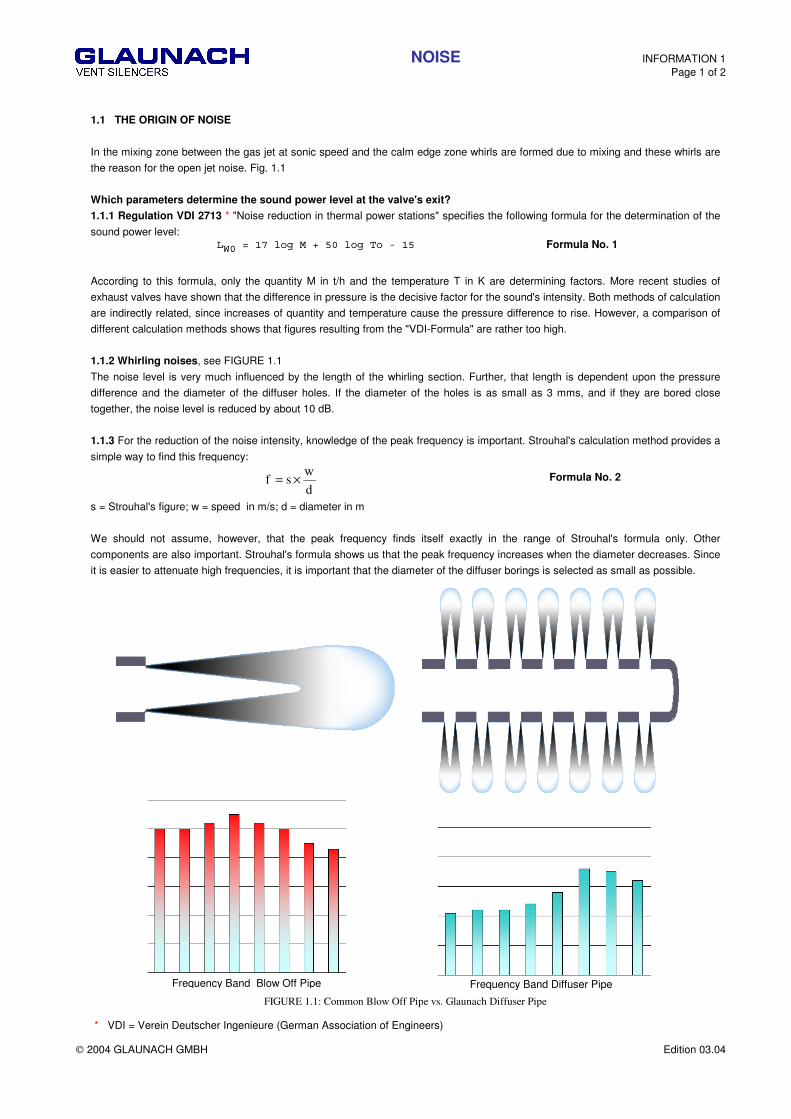
1.1 THE ORIGIN OF NOISE
In the mixing zone between the gas jet at sonic speed and the calm edge zone whirls are formed due to mixing and these whirls are
the reason for the open jet noise. Fig. 1.1
Which parameters determine the sound power level at the valve's exit?
1.1.1 Regulation VDI 2713 * "Noise reduction in thermal power stations" specifies the following formula for the determination of the
sound power level: ��������������� ��������� Formula No. 1
According to this formula, only the quantity M in t/h and the temperature T in K are determining factors. More recent studies of
exhaust valves have shown that the difference in pressure is the decisive factor for the sound's intensity. Both methods of calculation
are indirectly related, since increases of quantity and temperature cause the pressure difference to rise. However, a comparison of
different calculation methods shows that figures resulting from the "VDI-Formula" are rather too high.
1.1.2 Whirling noises, see FIGURE 1.1
The noise level is very much influenced by the length of the whirling section. Further, that length is dependent upon the pressure
difference and the diameter of the diffuser holes. If the diameter of the holes is as small as 3 mms, and if they are bored close
together, the noise level is reduced by about 10 dB.
1.1.3 For the reduction of the noise intensity, knowledge of the peak frequency is important. Strouhal's calculation method provides a
simple way to find this frequency:
d
wsf ×= Formula No. 2
s = Strouhal's figure; w = speed in m/s; d = diameter in m
We should not assume, however, that the peak frequency finds itself exactly in the range of Strouhal's formula only. Other
components are also important. Strouhal's formula shows us that the peak frequency increases when the diameter decreases. Since
it is easier to attenuate high frequencies, it is important that the diameter of the diffuser borings is selected as small as possible.
FIGURE 1.1: Common Blow Off Pipe vs. Glaunach Diffuser Pipe
* VDI = Verein Deutscher Ingenieure (German Association of Engineers)
Frequency Band Blow Off Pipe Frequency Band Diffuser Pipe

NOISE INFORMATION 1 Page 2 of 2
2004 GLAUNACH GMBH Edition 03.04
1.2 NOISE REDUCTION
In order to meet environmental demands, noise reduction requirements continue to increase. Design and construction of valves,
silencers, and piping systems are therefore constantly improved. Traditional vent silencer designs require an absorption component
to attenuate high frequency noise generated at the venting valve outlet. The expanded gas travels between baffles of straight or ring
shape, where noise energy is reduced through viscous friction. Such a construction is cumbersome, as it requires very large
silencers. This design necessitates the addition of an expansion chamber, installed upstream of the baffles, in which the turbulent
flow can be calmed.
1.2.1 How is it possible to reduce noise efficiently?
1. By transferring pressure drop from the valve to the silencer.
2. By making the diffuser borings as small as possible, thus limiting the development of whirls.
3. By making the diffuser openings as small as possible, so that the peak frequency reaches its highest level, since high
frequencies are easier to attenuate than lower ones.
Spring-loaded safety valves functioning automatically can be subjected to a back pressure amounting to 10 - 40 % of the set
pressure. This means that part of the pressure difference can be absorbed in a controlled process within the silencer.
A very high noise reduction can be achieved through concentrically arranged pressure stages, without the installation of absorbing
material.
If the diameter of the diffuser borings is kept small, the peak frequency becomes very high, as already explained before. Low-
frequency noise produced in the valve will still escape into the environment through the diffuser. It is therefore necessary to reduce
the valve noise level by taking the majority of the pressure drop across the silencer diffuser. Additional noise reduction can be
reached with the installation of absorbing material after the expansion section. Through the arrangement of absorption material
immediately after the pressure stages, developing whirls and the resulting noise are reduced and partially absorbed. A very high
noise reduction can be achieved with a small compact construction.
Using this design, the blowoff pipe is subjected to pressure, but the speed of the gas in the pipe slows down together with the noise
radiation emitted by the blowoff pipe after the valve. Thus the blowoff pipes can be kept smaller.
1.3 DESIGN OF THE DIFFUSER SILENCERS
Which requirements are to be met in the design of silencers?
1.3.1 Reduction of the valve noise
An advantageous design for optimization of the noise reduction is mentioned before.
Plant operators sometimes will not authorize pressure reduction taking place downstream of a safety valve. Almost all media which
are evacuated into the atmosphere for reason of security or for some other cause, are either pure, or mixed only with liquid
components; they can therefore be expanded by means of a diffuser silencer. The only reason which would prevent the installation of
a diffuser silencer would be the presence of dusty impurities, which develop during blowing off process of boilers and pipes.
For the blowing-off process of boilers, Glaunach supports rental silencers with diffuser cartridge for replacement
See chapter 2.3 - Rental Silencers.
Large solid particles bigger than the diffuser borings can obstruct gas flow through the silencer, therefore, a collection trap and
cleanout should be provided in the piping system prior to the silencer.
It is often overlooked that during free expansion after the valve the gas flows through the blowoff pipe at sonic speed, since the pipe
cannot be calculated oversized. This brings about a back pressure in the blowoff pipe and in spite of the free expansion the pipe
must be considered as a pressure vessel.
1.3.2 Avoidance of inherent noises
Thanks to the transfer of pressure to the silencer and controlled pressure reduction within the diffuser, the blowoff pipe can be a
smaller diameter, thus saving costs. The outlet velocity as well as the noise reflection from the valve determine the noise pollution
which is caused by the whole system. If the silencer is to provide for a high noise reduction, these criteria should not be disregarded.
Regulation VDI *) 3733 "Noises at pipes" gives bases for calculating noise source in pipelines and the damping of pipe-walls.
In chapter „Information 9, article 9.1,“ you find approximate values for the noise reflection of blowoff pipes, which can be expected.
* VDI = Verein Deutscher Ingenieure (German Association of Engineers)

SILENCERS & ACCESSORIES INFORMATION 2 Page 1 of 13
2004 GLAUNACH GMBH Edition 03.04
According to the requirements of the customers, our calculation program selects the correct and most economical silencer type.
With the following mentioned silencer types, various levels of noise reductions can be obtained. In noise sensitive areas where high
reduction is required, care should be taken to avoid noise radiated from the valve and related piping. These applications may require
insulation of both the valve and related piping, or insertion of the silencer into the roof of the building. The design should be made by
an acoustic specialist.
2.1 TYPES OF SILENCERS
2.1.1 Vent Silencer Type A
Absorption Silencer, for max. allowed back pressure below 0,2 bar/3 psi
Design: Shell with insulation and additional absorber
Noise reduction: by the arrangement of additional absorbers, almost any noise reduction can be achieved.
FIGURE 2.1.1: Type-A silencer
2.1.2 Vent Silencer Type D
Diffuser Silencer, for back pressure above 0,2 bar/3 psi.
Design: Glaunach Diffuser & Shell without insulation
Noise reduction: up to 50 dB
FIGURE 2.1.2: Type-D silencer
SILENCERS & ACCESSORIES INFORMATION 2 Page 2 of 13
2004 GLAUNACH GMBH Edition 03.04
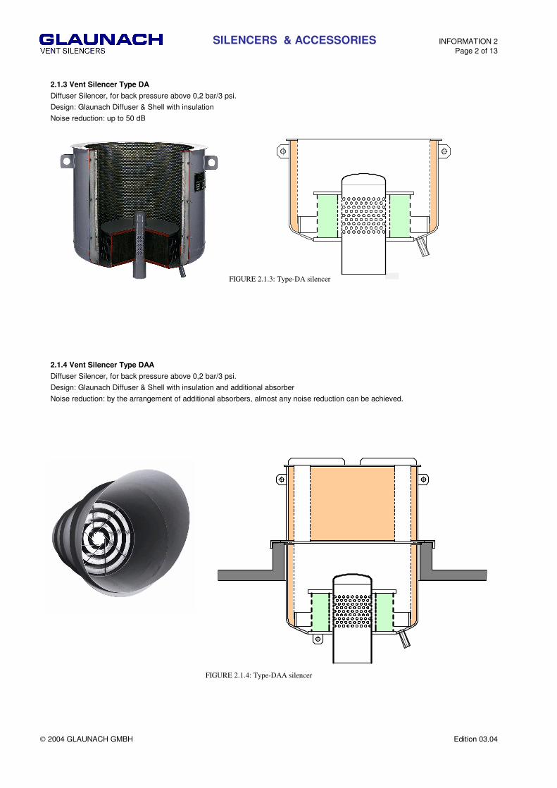
2.1.3 Vent Silencer Type DA
Diffuser Silencer, for back pressure above 0,2 bar/3 psi.
Design: Glaunach Diffuser & Shell with insulation
Noise reduction: up to 50 dB
FIGURE 2.1.3: Type-DA silencer
2.1.4 Vent Silencer Type DAA
Diffuser Silencer, for back pressure above 0,2 bar/3 psi.
Design: Glaunach Diffuser & Shell with insulation and additional absorber
Noise reduction: by the arrangement of additional absorbers, almost any noise reduction can be achieved.
FIGURE 2.1.4: Type-DAA silencer

SILENCERS & ACCESSORIES INFORMATION 2 Page 3 of 13
2004 GLAUNACH GMBH Edition 03.04
2.1.5 Inline Silencer
Diffuser Silencer, for back pressure above 0,2 bar/3 psi.
Design: Glaunach Diffuser for installation into a pipeline.
Noise reduction: up to 50 dB
FIGURE 2.1.5: Inline Silencer
2.1.6 Diffuser
Glaunach diffuser, for back pressure above 0,2 bar/3 psi.
Design: Customized Glaunach Diffuser
Noise reduction: up to 50 dB
FIGURE 2.1.6: Diffuser with collecting pipe with two inlets
SILENCERS & ACCESSORIES INFORMATION 2 Page 4 of 13
2004 GLAUNACH GMBH Edition 03.04
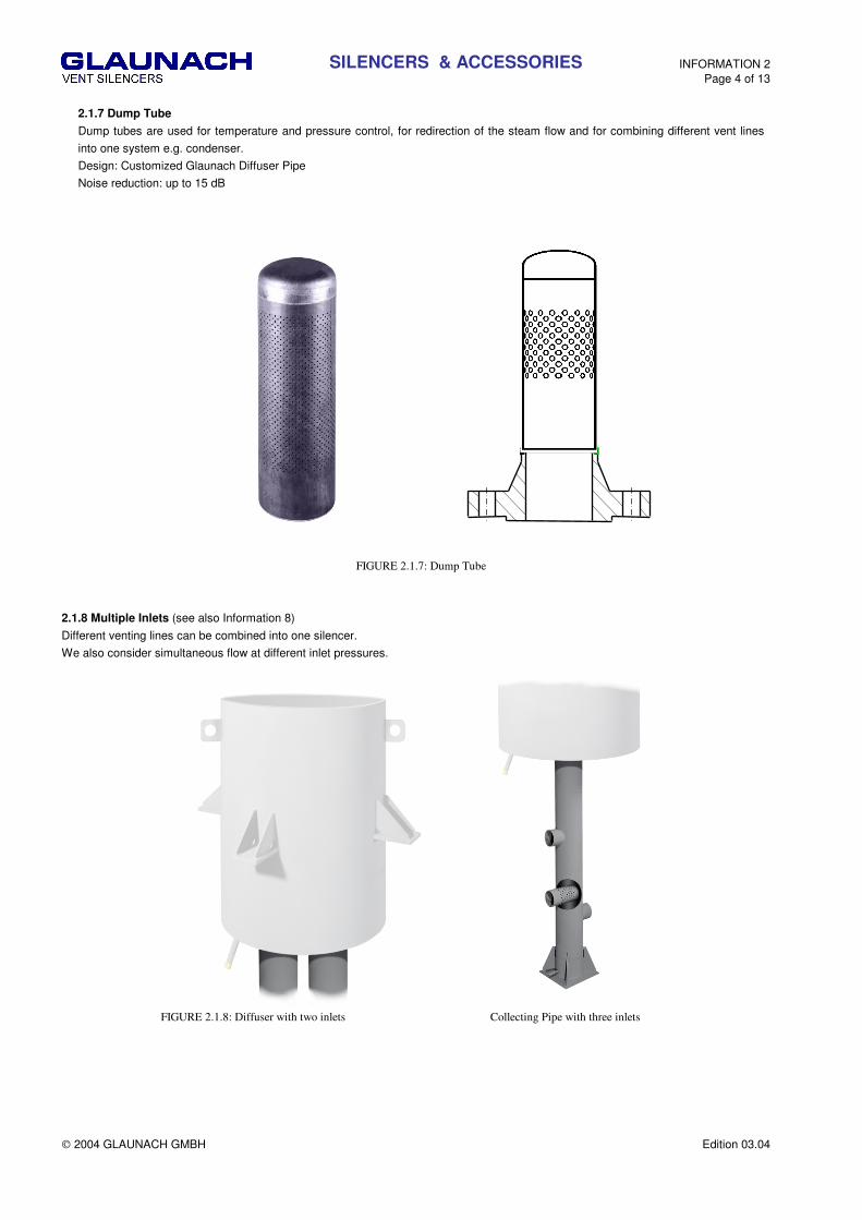
2.1.7 Dump Tube
Dump tubes are used for temperature and pressure control, for redirection of the steam flow and for combining different vent lines
into one system e.g. condenser.
Design: Customized Glaunach Diffuser Pipe
Noise reduction: up to 15 dB
FIGURE 2.1.7: Dump Tube
2.1.8 Multiple Inlets (see also Information 8)
Different venting lines can be combined into one silencer.
We also consider simultaneous flow at different inlet pressures.
FIGURE 2.1.8: Diffuser with two inlets Collecting Pipe with three inlets
SILENCERS & ACCESSORIES INFORMATION 2 Page 5 of 13
2004 GLAUNACH GMBH Edition 03.04
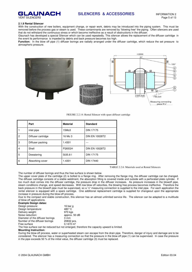
2.1.9 Rental Silencer With the construction of new boilers, equipment change, or repair work, debris may be introduced into the piping system. This must be removed before the process gas or steam is used. These contaminants are removed by “blowing free“ the piping. Often silencers are used that do not withstand the continuous stress or which become ineffective as a result of obstructions in the diffuser. Glaunach has developed a special Silencer which can be used repeatedly. This silencer allows the replacement of the diffuser cartridge in the event its performance is impeded by debris and back pressure becomes too high. Function: In the blow off pipe (1) diffuser borings are radially arranged under the diffuser cartridge, which reduce the set pressure to atmospheric pressure.
2000
355,6x8 60,3x4
Measuring connecting piece R½“
1800
5
6
4
2
3
1
100°
0°
FIGURE 2.2.14: Rental Silencer with spare diffuser cartridge
Part Material Standard
1 inlet pipe 15Mo3 DIN 17175
2 Diffuser cartridge 16 Mo 3 DIN EN 10028T2
3 Diffuser packing 1.4301 ---
4 Shell P265GH DIN EN 10028T2
5 Dewatering St35.8 I DIN 17175
6 Absorbing cover 1.4301 DIN 17440
TABLE 2.2.6: Materials used at Rental Silencers
The number of diffuser borings and thus the free surface is shown below. The upper cover plate of the cartridge (2) is bolted to a flange ring. After removing the flange ring, the diffuser cartridge can be changed. The diffuser cartridge consists of a stable weldment, the absorption filling is covered inside and outside with a perforated plate cylinder. If too much dust comes into the diffuser cartridge, the pressure drop in the diffuser increases. As pressure increases in the blowoff pipe, steam conditions change, and speed decreases. With low blow off velocities, the blowing free process becomes ineffective. Therefore the back pressure in the blowoff pipe must be supervised, so a ½“ measuring connection is supplied to the inlet pipe. For each application the rental silencer is equipped with a spare cartridge. One additional replacement cartridge is supplied for changeout upon the appropriate increase in pressure during the blow-off process. Due to the compact and stable construction, this silencer has an almost unlimited service life. The silencer can be adapted to a multitude of blow-off applications. Example Design datas: Design pressure: 16 bar g Design temperature: 480° C Delivery weight: 970 kgs Noise reduction: approx. 50 dB Diameter of the diffuser borings 3 mm Number of the diffuser borings 20832 pcs. Free surface 0,1472 m² The free surface can be reduced but not enlarged, therefore the capacity upward is limited. Mounting Instruction: During the blow-off process, water or superheated steam can escape from the drain pipe. Therefore, danger of injury and damage are to be considered. The silencer has a measuring connection so that the pressure in the blow-off pipe (1) can be supervised. In case the pressure in the pipe exceeds 50 % of the initial value, the diffuser cartridge (3) must be replaced.
SILENCERS & ACCESSORIES INFORMATION 2 Page 6 of 13
2004 GLAUNACH GMBH Edition 03.04
2.2 ACCESSORIES
With the afore mentioned silencer types, the following supplementary equipments are available:
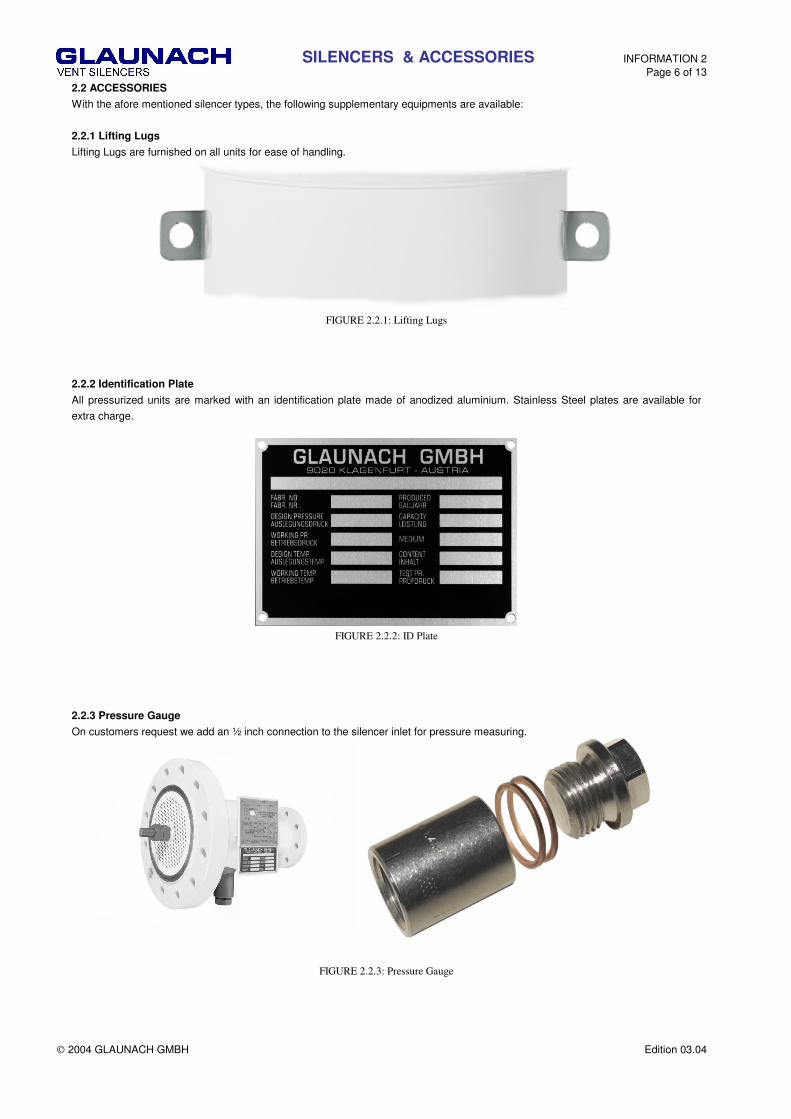
2.2.1 Lifting Lugs
Lifting Lugs are furnished on all units for ease of handling.
FIGURE 2.2.1: Lifting Lugs
2.2.2 Identification Plate
All pressurized units are marked with an identification plate made of anodized aluminium. Stainless Steel plates are available for
extra charge.
FIGURE 2.2.2: ID Plate
2.2.3 Pressure Gauge
On customers request we add an ½ inch connection to the silencer inlet for pressure measuring.
FIGURE 2.2.3: Pressure Gauge

SILENCERS & ACCESSORIES INFORMATION 2 Page 7 of 13
2004 GLAUNACH GMBH Edition 03.04
2.2.4 Dewatering Pipe
All Silencers are equipped with a drainage pipe for condensation and rainwater.
FIGURE 2.2.4: Drainage
2.2.5 Eave Ring (protects pipe insulation from rain water)
The supplementary type ER1 is used for the small silencer diameter of the type B, the supplementary type ER2 for silencers starting
from 900 mm in diameter. The numbers behind the type designation indicate the nominal diameter D of the silencer.
Example: ER2 - 1600 means nominal diameter of silencer Da = 1600 mm
Diameter of the collar sheet DTR = 1500 mm
DTR DTR
t
Da Da
t
ER1 ER2
FIGURE 2.2.5 Eave Ring
Suppl. equipment
DTR t kg Suppl. equipment DTR t kg
ER1 744 50 4,6 ER2-2200 2100 50 13,2 ER2-900 800 50 5 ER2-2400 2300 50 14,5 ER2-1000 900 50 6 ER2-2600 2500 50 15,7 ER2-1100 1000 50 6,3 ER2-2800 2700 50 17 ER2-1200 1100 50 7 ER2-3000 2900 50 18,2 ER2-1400 1300 50 8,2 ER2-1600 1500 50 9,4 ER2-1800 1700 50 10,7 ER2-2000 1900 50 12
Table 2.2.1 Eave Ring, dimension & weight
SILENCERS & ACCESSORIES INFORMATION 2 Page 8 of 13
2004 GLAUNACH GMBH Edition 03.04
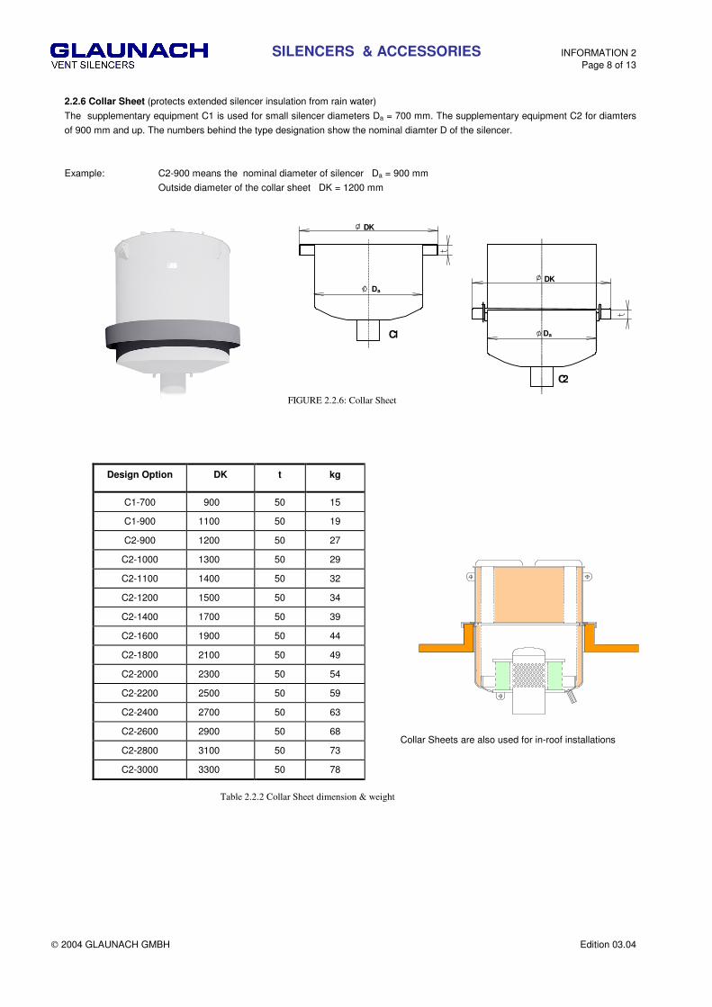
2.2.6 Collar Sheet (protects extended silencer insulation from rain water)
The supplementary equipment C1 is used for small silencer diameters Da = 700 mm. The supplementary equipment C2 for diamters
of 900 mm and up. The numbers behind the type designation show the nominal diamter D of the silencer.
Example: C2-900 means the nominal diameter of silencer Da = 900 mm
Outside diameter of the collar sheet DK = 1200 mm
DK
DK
C1
C2
Da
Da
FIGURE 2.2.6: Collar Sheet
Table 2.2.2 Collar Sheet dimension & weight
Design Option DK t kg
C1-700 900 50 15
C1-900 1100 50 19
C2-900 1200 50 27
C2-1000 1300 50 29
C2-1100 1400 50 32
C2-1200 1500 50 34
C2-1400 1700 50 39
C2-1600 1900 50 44
C2-1800 2100 50 49
C2-2000 2300 50 54
C2-2200 2500 50 59
C2-2400 2700 50 63
C2-2600 2900 50 68
C2-2800 3100 50 73
C2-3000 3300 50 78
Collar Sheets are also used for in-roof installations

SILENCERS & ACCESSORIES INFORMATION 2 Page 9 of 13
2004 GLAUNACH GMBH Edition 03.04
Da
a = Da + 2 x t
Da
2.2.7 Brackets
When mounting brackets are required, the designs shown below are the basis for our calculation.
Design B1 for Design B2 for Type D and DA Type DAA
FIGURE 2.2.7 Mounting Brackets
Silencer Design B1 Design B2
Diameter t b s1 c s2 kg t b s1 c s2 kg
700-1100 150 100 10 130 8 7 300 100 10 280 8 18,5
1200-1500 150 150 10 130 8 9,5 300 150 10 280 8 23
1600-1900 200 150 12 180 10 18 300 150 10 280 8 23
> 2000 200 150 15 180 10 21 300 150 15 280 10 36 TABLE 2.2.3: Brackets, dimension & weight
2.2.8 Legs
Customized legs are available upon request
FIGURE 2.2.8 Mounting Legs

SILENCERS & ACCESSORIES INFORMATION 2 Page 10 of 13
2004 GLAUNACH GMBH Edition 03.04
2.2.9 Flange Kit
we supply flanges of most common standards, including nuts, bolts and gasket.
FIGURE 2.2.9 Flange
2.2.10 Heating
Silencers can be equipped with a heating system to prevent ice plugs at the drainage
More details can be found at Information 10
FIGURE 2.2.10: Electrical Heating System
2.2.11 Outlet Accessories
Customized equipment for the silencer outlet can be supported upon request.
e.g. redirection, elongation, bird screen
FIGURE 2.2.11: Goose Neck Extension Bird Screen
SILENCERS & ACCESSORIES INFORMATION 2 Page 11 of 13
2004 GLAUNACH GMBH Edition 03.04
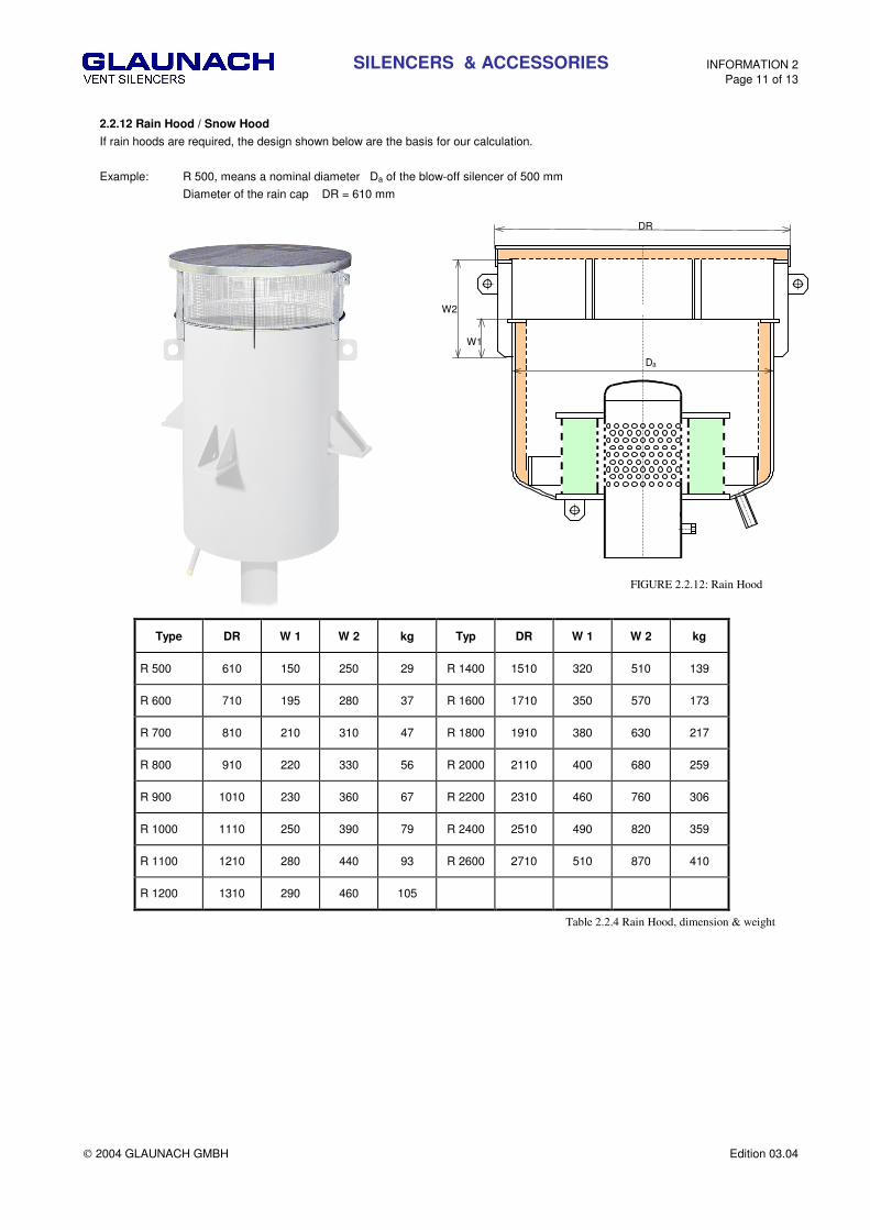
2.2.12 Rain Hood / Snow Hood
If rain hoods are required, the design shown below are the basis for our calculation.
Example: R 500, means a nominal diameter Da of the blow-off silencer of 500 mm
Diameter of the rain cap DR = 610 mm
DR
Da
W1
W2
FIGURE 2.2.12: Rain Hood
Type DR W 1 W 2 kg Typ DR W 1 W 2 kg
R 500 610 150 250 29 R 1400 1510 320 510 139
R 600 710 195 280 37 R 1600 1710 350 570 173
R 700 810 210 310 47 R 1800 1910 380 630 217
R 800 910 220 330 56 R 2000 2110 400 680 259
R 900 1010 230 360 67 R 2200 2310 460 760 306
R 1000 1110 250 390 79 R 2400 2510 490 820 359
R 1100 1210 280 440 93 R 2600 2710 510 870 410
R 1200 1310 290 460 105
Table 2.2.4 Rain Hood, dimension & weight

SILENCERS & ACCESSORIES INFORMATION 2 Page 12 of 13
2004 GLAUNACH GMBH Edition 03.04
Expansion Joints (vertical & horizontal movement)
Sliding Brackets (horizontal movement)
2.2.13 Expansion Compensation
for vertical and/or horizontal movement of the entrance pipe.
sFIGURE 2.13
FIGURE 2.2.13: Systems for expansion compensation
Type De kg Type De kg
SD 80 88,9 4,7 SD 350 355,6 14,25 SD 100 114,3 5,5 SD 400 406,0 16 SD 125 139,7 6,5 SD 450 457,0 17,9 SD 150 168,3 7,5 SD 500 508,0 19,7 SD 200 219,1 9,3 SD 600 610,0 23,4 SD 225 244,5 10,25 SD 700 711,0 27 SD 250 273,0 11,2 SD 800 813,0 30,7 SD 300 323,9 13
TABLE 2.2.5: Sliding Diffuser, dimension & weight
de
dSD
Stuffing box
Sliding diffuser Sliding Diffuser
(vertical movement)
SILENCERS & ACCESSORIES INFORMATION 2 Page 13 of 13
2004 GLAUNACH GMBH Edition 03.04
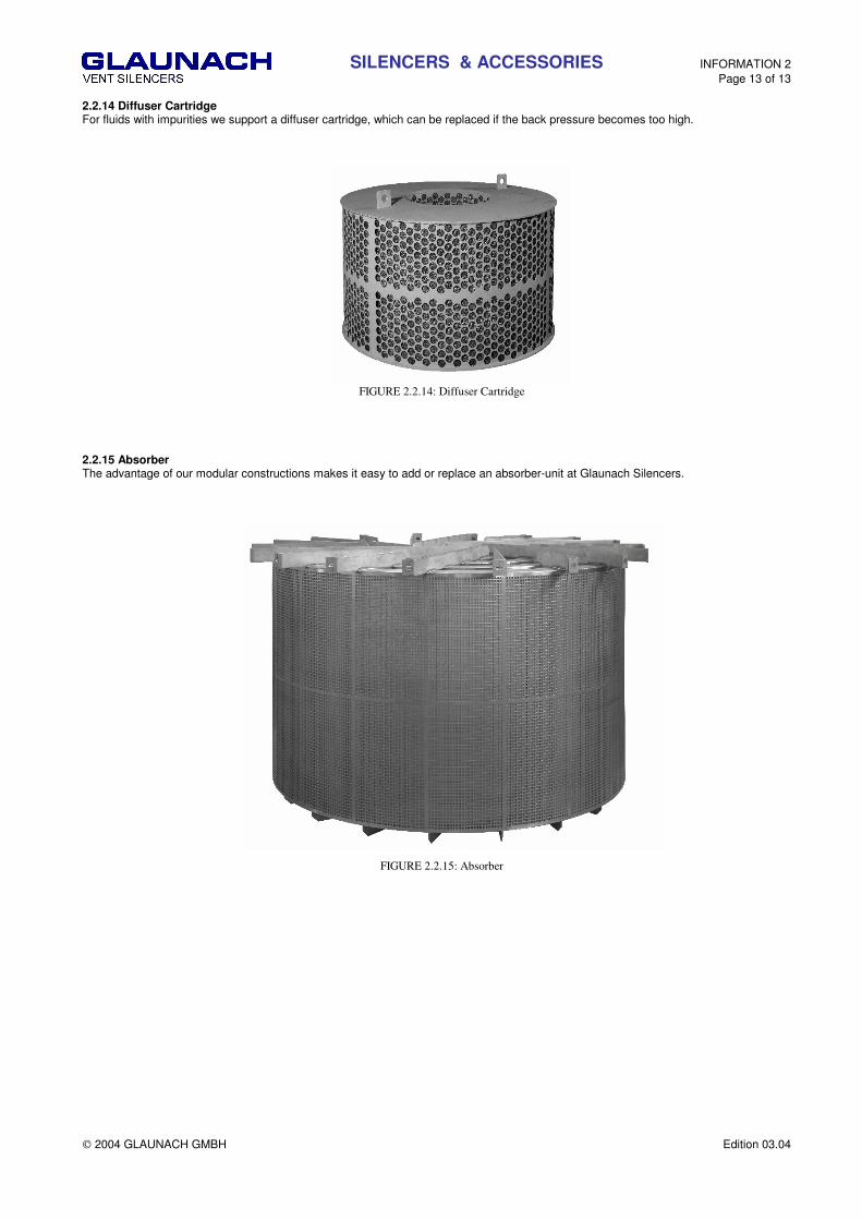
2.2.14 Diffuser Cartridge For fluids with impurities we support a diffuser cartridge, which can be replaced if the back pressure becomes too high.
FIGURE 2.2.14: Diffuser Cartridge
2.2.15 Absorber The advantage of our modular constructions makes it easy to add or replace an absorber-unit at Glaunach Silencers.
FIGURE 2.2.15: Absorber

CALCULATION INFORMATION 3 Page 1 of 4
2004 GLAUNACH GMBH Edition 03.04
The following mentioned calculations are used for a rough silencer selection. The exact calculations are done at GLAUNACH. 3.1 THE NOISE EVALUATION LEVEL Lr The evaluation level must be specified by the end user. This level must conform to the geographic requirements, in conjuction with the requirements of the end user. 3.1.1 Personell protection-OSHA 1910.95
When employees are subjected to sound exceeding those listed in Table 3.1.1, feasible administrative or engineering controls shall be utilized. If such controls fail to reduce sound levels within the levels of Table 3.1.1, personal protective equipment shall be provided and used to reduce sound levels within the levels of the table.
If the variations in noise level involve maxima at intervals of 1 second or less, it is to be considered continuous
____________ PERMISSIBLE NOISE EXPOSURES 1
__________ | Duration per day, hours | Sound level dBA slow response _____________________________ __________________________ | 8 | 90 6 | 92 4 | 95 3 | 97 2 | 100 1 1/2 | 102 1 | 105 1/2 | 110 1/4 or less | 115 ________________________________________________________
Table 3.1.1: Permissible Noise Exposures
1 When the daily noise exposure is composed of two or more periods of noise exposure of different levels, their combined effect should be considered, rather than the individual effect of each. If the sum of the following fractions: C(1)/T(1) + C(2)/T(2) C(n)/T(n) exceeds unity, then, the mixed exposure should be considered to exceed the limit value. Cn indicates the total time of exposure at a specified noise level, and Tn indicates the total time of exposure permitted at that level. Exposure to impulsive or impact noise should not exceed 140 dB peak sound pressure level.
It is important to know that if several valves open at the same time,there is an additive effect to the overall noise level. 3.2 SOUND LEVEL ADJUSTMENTS DETERMINED BY DISTANCE ∆∆∆∆Lr
As mentioned under 3.1, normally the sound level is evaluated after the silencer at a specific distance. When calculating the sound
level adjsutments the following points have to be considered.
3.2.1 Hemispherical radiation
If the blow off silencer is mounted on the roof, noise radiates out hemispherically into the environment. The sound pressure level
decreases according to the following formula:
∆�������������π���� in dB; Formula 3
3.2.2 Transmission factors The sound level adjustments calculated according to 3.2.1 to 3.2.2 are only valid within 25 m from the noise source. If the evaluation level is at a distance greater than 25 meters, the following parameters still are to be considered:
∆LΦ = direction correction in dB ∆Ls = screen measure in dB
∆La = air reflecting measure in dB ∆Lv = vegetation attenuation measure in dB
∆Lrx = area reflecting measure in dB ∆Lb = bottom attenuation measure in dB
We cannot elaborate upon all parameters, but the following points are important:

CALCULATION INFORMATION 3 Page 2 of 4
2004 GLAUNACH GMBH Edition 03.04
3.2.2.1 Direction correction
110°
90°
80°
45°
Silencer
Roof
0°
Picture 3.2.1 : angle of reflection
Vertical silencers direct the sound energy up. For vertical applications, depending upon the angle of reflection, the following increases apply:
Angle of reflection Φ 110° - 90 ° 90 ° - 80 ° 80 ° - 45 ° 0 °
Correction in dB 0 1 3 20
Φ= angle of reflection between silencer axis and evaluation point. Table 3.2.1
Because of the high level increase in front of the silencer opening, the silencer should always blow upward. Rain caps reflect the sound downward, even when they absorb the sound at the lower surface. Therefore, we recommend that they be used only when absolutely necessary. Under normal conditions, the point of evaluation is below the horizontal axis of the silencer outlet. For such points, a correction is not necessary. Only in exceptional cases, when the point of evaluation is above the horizontal axis of the silencer outlet, is a correction necessary. 3.2.2.2 Air reflection measure ∆∆∆∆La
Sound absorption in the air depends on the frequency, temperature, and humidity. The following chart represents approximate frequency adjustments for dB/m at 10°C and an air humidity of 70%.
f(Hz) 125 250 500 1000 2000 4000 8000
dB / m 0,001 0,001 0,002 0,004 0,008 0,021 0,052 Table 3.2.2
After the silencer, the peak frequencies lie in a range between 2000 and 8000 Hz. At distances over 100 m air reflection measure ∆La should be considered.
3.3 CALCULATION OF THE VALVE - SOUND POWER LEVEL LW0
In most cases the sound power level of the valve is not known. GLAUNACH uses one of two calculations standards to obtain a
value for the purpose of silencer selction. The following are the two calculations used.
VDI 2713 ������������� ��������
ANSI/API RP 521 ��������� ��������������� ������������������������� ����!�"��� �"��

CALCULATION INFORMATION 3 Page 3 of 4
2004 GLAUNACH GMBH Edition 03.04
3.4 DETERMINATION OF DYNAMIC INSERTION LOSS Di
If evaluation level Lr requires that adjustments be made (∆lr ) and the transmission factors ∆La, ∆Lrx, ∆Ls, ∆Lv, ∆Lb are added or
deducted respectively, you receive the most permissible sound power level of the silencer LW.
�����������∆�����∆�Φ���∆�# in dB Formula 5
The transmission factors . ∆Lrx, ∆Lrs, ∆Lrv, ∆Lrb.are not considered here as their calculations are very complicated. The necessary
silencer attenuation is determined by subtracting results of Formula 5 above from the required silenced level. See Formula 6 below.
$%����������� Formula 6
3.5 EXAMPLES Two examples of calculation for the free field:
1) near the noise source 2) evaluation level at larger distance.
To both cases applies:
Valve capacity G = 100 t/h Temp. in front of the valve t = 500°C Pressure in front of the valve p0 = 100 bar
The silencer is mounted on the roof of the boiler house at a height of 30 m. 3.5.1 Required evaluation level Lr = 85 dB(A) at a distance of 7 meters
����������������� ���������� ������� ������&'�()�*� Formula 1
∆�������������π��������'&��() Formula 3
�������! ��'&��������()�*� Formula 5
$%������&'��������� �&'�() Formula 6
Required dynamic insertion loss is Di = 53,4 dB Calculations indicate that insulation of the vent pipe between the roof and silencer is required. In order to prevent contamination at the silencer outlet from noise radiated at the valve body ,the valve should be arranged inside or insulated. 3.5.2 Required evaluation level Lr = 50 dB(A) at a distance of 300 meters on a hill, 50 meters over the silencer opening
∆�������������π���������� �& �()
The angle of reflection is calculated as follows: Φ = 90 - arc tan (50/300) = 80,5 °. According to table 3.2.1,
correction value ∆LΦ
= 3 dB
The frequency maximum after the silencer is about 2000 cycles per second, the correction value is calculated according
to table 3.2.2
∆�#����&��!�×��������&'�()�
�
����� ���� �& ��������&'��������&��()�*��
�
$%������&'������&������ �& �()�
As with the previous example, accoustic insulation must be planned between roof and silencer eaves ring. The valve must be
arranged inside
CALCULATION INFORMATION 3 Page 4 of 4
2004 GLAUNACH GMBH Edition 03.04
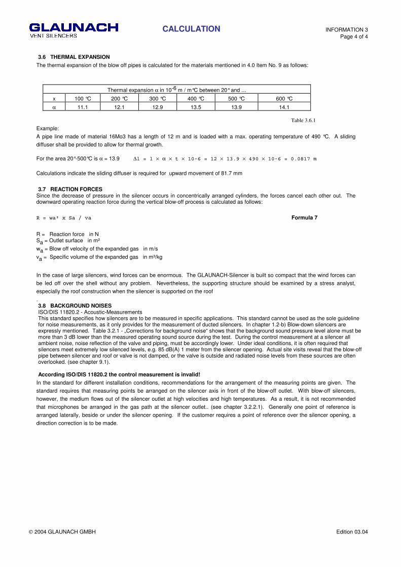
3.6 THERMAL EXPANSION
The thermal expansion of the blow off pipes is calculated for the materials mentioned in 4.0 Item No. 9 as follows:
Thermal expansion α in 10-6 m / m°C between 20° and ...
x 100 °C 200 °C 300 °C 400 °C 500 °C 600 °C
α 11.1 12.1 12.9 13.5 13.9 14.1 Table 3.6.1
Example:
A pipe line made of material 16Mo3 has a length of 12 m and is loaded with a max. operating temperature of 490 °C. A sliding
diffuser shall be provided to allow for thermal growth. For the area 20°-500°C is α = 13.9 ∆������×�α�×� �×�����������×������×�'���×�����������!���+
Calculations indicate the sliding diffuser is required for upward movement of 81.7 mm
3.7 REACTION FORCES Since the decrease of pressure in the silencer occurs in concentrically arranged cylinders, the forces cancel each other out. The downward operating reaction force during the vertical blow-off process is calculated as follows:
�����#��,�-#���.# Formula 7
R = Reaction force in N Sa = Outlet surface in m²
wa = Blow off velocity of the expanded gas in m/s
va = Specific volume of the expanded gas in m³/kg
In the case of large silencers, wind forces can be enormous. The GLAUNACH-Silencer is built so compact that the wind forces can
be led off over the shell without any problem. Nevertheless, the supporting structure should be examined by a stress analyst,
especially the roof construction when the silencer is supported on the roof
. 3.8 BACKGROUND NOISES ISO/DIS 11820.2 - Acoustic-Measurements This standard specifies how silencers are to be measured in specific applications. This standard cannot be used as the sole guideline for noise measurements, as it only provides for the measurement of ducted silencers. In chapter 1.2-b) Blow-down silencers are expressly mentioned. Table 3.2.1 - „Corrections for background noise“ shows that the background sound pressure level alone must be more than 3 dB lower than the measured operating sound source during the test. During the control measurement at a silencer all ambient noise, noise reflection of the valve and piping, must be accordingly lower. Under ideal conditions, it is often required that silencers meet extremely low silenced levels, e.g. 85 dB(A) 1 meter from the silencer opening. Actual site visits reveal that the blow-off pipe between silencer and roof or valve is not damped, or the valve is outside and radiated noise levels from these sources are often overlooked. (see chapter 9.1). According ISO/DIS 11820.2 the control measurement is invalid!
In the standard for different installation conditions, recommendations for the arrangement of the measuring points are given. The
standard requires that measuring points be arranged on the silencer axis in front of the blow-off outlet. With blow-off silencers,
however, the medium flows out of the silencer outlet at high velocities and high temperatures. As a result, it is not recommended
that microphones be arranged in the gas path at the silencer outlet.. (see chapter 3.2.2.1). Generally one point of reference is
arranged laterally, beside or under the silencer opening. If the customer requires a point of reference over the silencer opening, a
direction correction is to be made.
MATERIALS, CODES & STANDARDS INFORMATION 4 Page 1 of 3
2004 GLAUNACH GMBH Edition 03.04
4.1 GENERAL
Materials used in the construction of our standard silencers follow European standards and are stated on the following pages. In
some cases, we may substitute higher grade materials in place of lower grade materials.
Example; P265GH or ST35.8 I - 16 Mo3; instead of 1.4301 - 1.454 or instead of 1.4541 - 1.4436.
Upon request, ASTM-materials and others may be used. Since blow-off silencers are normally loaded for short durations of time,
maximum actual working time is based on 10,000 hrs.
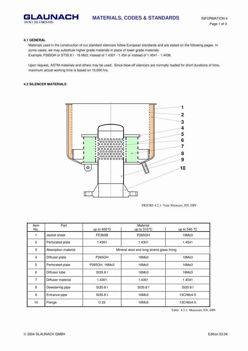
4.2 SILENCER MATERIALS
1
2
3
4
5
6
7
8
9
10
FIGURE 4.2.1: Vent Silencers, EN, DIN
Item Part Material No. up to 400°C up to 510°C up to 540 °C
1 Jacket sheet FE360B P265GH 16Mo3
2 Perforated plate 1.4301 1.4301 1.4541
3 Absorption material Mineral wool and long strand glass lining
4 Diffuser plate P265GH 16Mo3 16Mo3
5 Perforated plate P265GH, 16Mo3 16Mo3 16Mo3
6 Diffuser tube St35.8 I 16Mo3 16Mo3
7 Diffuser material 1.4301 1.4301 1.4541
8 Dewatering pipe St35.8 I St35.8 I St35.8 I
9 Entrance pipe St35.8 I 16Mo3 13CrMo4-5
10 Flange C 22 16Mo3 13CrMo4-5
Table 4.2.1: Materials, EN, DIN
MATERIALS, CODES & STANDARDS INFORMATION 4 Page 2 of 3
2004 GLAUNACH GMBH Edition 03.04
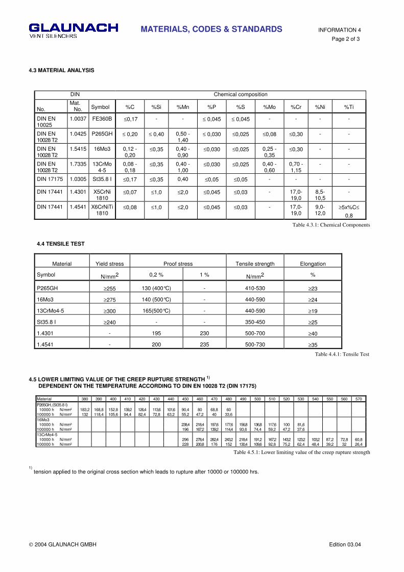
4.3 MATERIAL ANALYSIS
DIN Chemical composition
No.
Mat. No. Symbol %C %Si %Mn %P %S %Mo %Cr %Ni %Ti
DIN EN 10025
1.0037 FE360B ≤0,17 - - ≤ 0,045 ≤ 0,045 - - - -
DIN EN 10028 T2
1.0425 P265GH ≤ 0,20 ≤ 0,40 0,50 - 1,40
≤ 0,030 ≤0,025 ≤0,08 ≤0,30 - -
DIN EN 10028 T2
1.5415 16Mo3 0,12 - 0,20
≤0,35 0,40 - 0,90
≤0,030 ≤0,025 0,25 - 0,35
≤0,30 - -
DIN EN 10028 T2
1.7335 13CrMo4-5
0,08 - 0,18
≤0,35 0,40 - 1,00
≤0,030 ≤0,025 0,40 - 0,60
0,70 -1,15
- -
DIN 17175 1.0305 St35.8 I ≤0,17 ≤0,35 0,40 ≤0,05 ≤0,05 - - - -
DIN 17441 1.4301 X5CrNi 1810
≤0,07 ≤1,0 ≤2,0 ≤0,045 ≤0,03 - 17,0-19,0
8,5-10,5
-
DIN 17441 1.4541 X6CrNiTi 1810
≤0,08 ≤1,0 ≤2,0 ≤0,045 ≤0,03 - 17,0-19,0
9,0-12,0
≥5x%C≤
0,8
Table 4.3.1: Chemical Components
4.4 TENSILE TEST
Material
Yield stress
Proof stress
Tensile strength
Elongation
Symbol N/mm2 0,2 % 1 % N/mm2 %
P265GH ≥255 130 (400°C) - 410-530 ≥23
16Mo3 ≥275 140 (500°C) - 440-590 ≥24
13CrMo4-5 ≥300 165(500°C) - 440-590 ≥19
St35.8 I ≥240 - - 350-450 ≥25
1.4301 - 195 230 500-700 ≥40
1.4541 - 200 235 500-730 ≥35
Table 4.4.1: Tensile Test 4.5 LOWER LIMITING VALUE OF THE CREEP RUPTURE STRENGTH
1)
DEPENDENT ON THE TEMPERATURE ACCORDING TO DIN EN 10028 T2 (DIN 17175)
Material 380 390 400 410 420 430 440 450 460 470 480 490 500 510 520 530 540 550 560 570 P265GH, (St35.8 I) 10000 h N/mm² 183,2 168,8 152,8 139,2 126,4 113,6 101,6 90,4 80 68,8 60 100000 h N/mm² 132 118,4 105,6 94,4 82,4 72,8 63,2 55,2 47,2 40 33,6 16Mo3 10000 h N/mm² 238,4 218,4 197,6 177,6 156,8 136,8 117,6 100 81,,6 100000 h N/mm² 196 167,2 139,2 114,4 93,6 74,4 59,2 47,2 37,6 13CrMo4-5 10000 h N/mm² 296 278,4 262,4 243,2 218,4 191,2 167,2 143,2 123,2 103,2 87,2 72,8 60,8 100000 h N/mm² 228 200,8 176 152 130,4 109,6 92,8 75,2 62,4 48,4 39,2 32 26,4
Table 4.5.1: Lower limiting value of the creep rupture strength
1)
tension applied to the original cross section which leads to rupture after 10000 or 100000 hrs.
MATERIALS, CODES & STANDARDS INFORMATION 4 Page 3 of 3
2004 GLAUNACH GMBH Edition 03.04
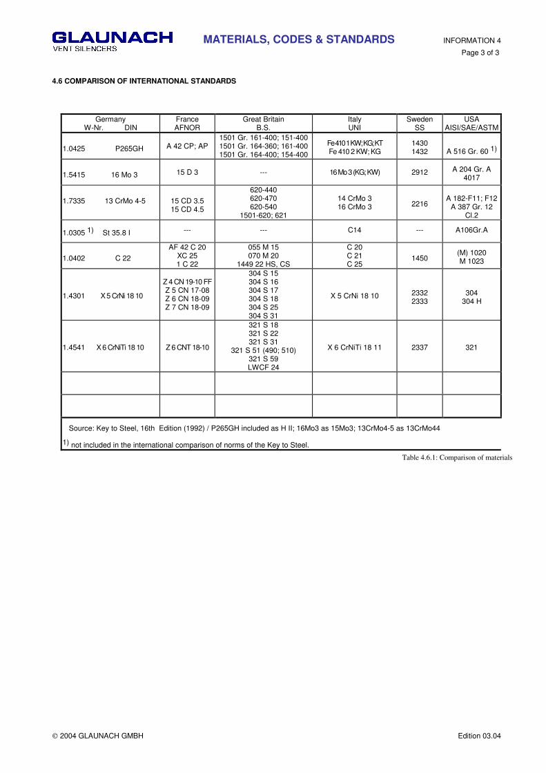
4.6 COMPARISON OF INTERNATIONAL STANDARDS
Germany
W-Nr. DIN France AFNOR
Great Britain B.S.
Italy UNI
Sweden SS
USA AISI/SAE/ASTM
1.0425 P265GH
A 42 CP; AP
1501 Gr. 161-400; 151-400 1501 Gr. 164-360; 161-400 1501 Gr. 164-400; 154-400
Fe 410 1 KW; KG; KT Fe 410 2 KW; KG
1430 1432 A 516 Gr. 60 1)
1.5415 16 Mo 3
15 D 3
---
16 Mo 3 (KG; KW)
2912 A 204 Gr. A
4017
1.7335 13 CrMo 4-5 15 CD 3.5 15 CD 4.5
620-440 620-470 620-540
1501-620; 621
14 CrMo 3 16 CrMo 3
2216
A 182-F11; F12
A 387 Gr. 12 Cl.2
1.0305 1) St 35.8 I --- --- C14 --- A106Gr.A
1.0402 C 22
AF 42 C 20 XC 25 1 C 22
055 M 15 070 M 20
1449 22 HS, CS
C 20 C 21 C 25
1450 (M) 1020 M 1023
1.4301 X 5 CrNi 18 10
Z 4 CN 19-10 FF Z 5 CN 17-08 Z 6 CN 18-09 Z 7 CN 18-09
304 S 15 304 S 16 304 S 17 304 S 18 304 S 25 304 S 31
X 5 CrNi 18 10
2332 2333
304 304 H
1.4541 X 6 CrNiTi 18 10
Z 6 CNT 18-10
321 S 18 321 S 22 321 S 31
321 S 51 (490; 510) 321 S 59 LWCF 24
X 6 CrNiTi 18 11
2337
321
Source: Key to Steel, 16th Edition (1992) / P265GH included as H II; 16Mo3 as 15Mo3; 13CrMo4-5 as 13CrMo44
1) not included in the international comparison of norms of the Key to Steel.
Table 4.6.1: Comparison of materials

CORROSION PROTECTION INFORMATION 5
Page 1 of 1
2004 GLAUNACH GMBH Edition 03.04
5.1 GENERAL INFORMATION
Attention to detail while applying corrosion protection extends the service life of silencers substantially. For parts, which are particularly corrosion endangered, (for example thin perforated plates and flowed through absorbing materials), the European equivalent to 304 stainless steel is used. All carbon steels are sand-blasted and get a temperature-steady protective coating. The flowloaded inside receives a single and the exterior surface a double primer. After final assembly the exterior paint should be repaired and possibly a top coat should be applied. During transport and assembling slight damages of the coating can hardly be avoided. For repair an original color is enclosed to the supply, and also a roll for applying the color. The blow-off pipes are derusted inside and lightly oiled. The inlet pipe and diffuser get no protective coating, as it would be cleared away during the blow-off process. Contaminates, such as rust and construction debris inside the piping system, should be kept away from the silencer as the diffuser can be obstructed, limiting the free area of the diffuser. See chapter 2.3.
5.2 SURFACE TREATMENT OF CARBON STEELS
According to standard for the silencers the following surface treatment is provided:
5.2.1. Silencer Inlet Pipe and Diffuser
• Hand tool cleaning
• slight coating with oil
5.2.2 Silencer Shell Internal Surface
• Blast clean by compressed air with cast iron grit
• Surface preparation grade SA21/2 accord. to DIN 55928T4
• Single coating with ethyl silciate zinc rich primer
5.2.3 Exterior surfaces up to 400°C temperature load
• Blast clean by compressed air with cast iron grit
• Surface preparation grade SA21/2 accord. to DIN 55928T4
• Double coating with ethyl silicate zinc rich primer
This coating guarantees a temperature constancy according to the manufacturer data. At a temperature load of approximately 450°C (840°F), this coating loses its corrosion resistance since the zinc particles melt. Nevertheless, pure aluminium silicon coatings with a temperature constancy of more than 500°C (932°F) offer poor corrosion protection. Even without temperature load, pure aluminum silicon coatings may not prevent corrosion.
5.2.4 Exterior surfaces over 400°C (450°C) temperature load
• Blast clean by compressed air with cast iron grit
• Surface preparation grade SA3 according to DIN 55928T4
• Coating with aluminium in an electric arc spraying process
• Sealer with aluminium silicon color.

QUALITY ASSURANCE INFORMATION 6
Page 1 of 2
2004 GLAUNACH GMBH Edition 03.04
6.1 GENERAL INFORMATION
Quality Assurance covering construction and production of blow-off silencers follows standards and rules of (ISO, TRD, TRB, AD-instructional pamphlets) or purchaser's own specified quality assurance procedures and quality assurance system.
6.1.1 Quality of Materials:
The quality of the materials for pressure leading parts is determined by Inspection Certificates according. to DIN 50049 (DIN EN
10204):
• 3.1A for pre material 16Mo3, 13CrMo4-5
• 3.1B for pre material P265GH, St35.8 I or ASTM materials
• 2.2 for all other materials
6.1.2 Quality check of the welded joints:
Our company furnishes proof that conditions according to AD-brochure HP 0 are fulfilled. Conditions related to appropriate
production according to the general principles for materials are given. We have appropriate:
• production and welding equipment, • welding personnel and welding supervision personnel, • testing facilities, • test personnel and test supervision personnel.
If necessary, welding qualification can be supplied in accordance with ASME SEC.IX.
If a “Code“ stamp according to ASME is prescribed, the inspection is made by the “Authorized Inspection Agency“
6.2 QUALITY MANAGEMENT
GLAUNACH’s Quality Management System is in accordance with ISO 9001. Our Quality System was first certified in 1993 by
Lloyd’s Register and continues to be constantly supervised and recertified annually.

QUALITY ASSURANCE INFORMATION 6
Page 2 of 2
2004 GLAUNACH GMBH Edition 03.04

INSTALLATION INFORMATION 7
Page 1 of 4
2004 GLAUNACH GMBH Edition 03.04
7.1 ARRANGEMENT OF THE SILENCERS
Blow-off silencers should be mounted on the roof whenever possible. As the medium evacuated by the valve expands to reach
atmospheric pressure, the silencer outlet velocity must be low enough to exclude perturbations due to flow noise. If a pipeline is
provided downstream of the silencer, the piping should be sized sufficient to keep gas velocities low. Additionally, bends should be
avoided to avoid turbulence and flow generated noise. With pressure reducing diffuser silencers the pipe section can be kept small,
thanks to the small specific volume in the pipe section. In this pipe, high gas velocities should be avoided, as they generate flow
noise and the maximum admissible backpressure downstream of the valve, should be reduced in a controlled process within the
silencer. The GLAUNACH blow-off silencers are of a light and compact construction. The simplest arrangement consists in the
fixation of the silencer on the end of the blow-off pipe without supplementary support. The blow-off pipe carries the silencer. Wind
forces can be deflected by a device in the roof construction.
7.2 FIXATION OF THE SILENCERS
When blow-off pipes are subject to temperature loads, the elongations must be taken into account. There are several possibilities for
mounting silencers
7.2.1 Supporting structure under roof with long blowoff pipe
FIGURE 7.1
The silencer is mounted at the blow-off pipe which is supported under the roof. In case of elongations due to temperature, the silencer moves upwards. The only precaution to be taken is the fitting of a suitable seal at the roof's passage. Wall thickness of the blow-off pipe must be thick enough to withstand wind forces.

INSTALLATION INFORMATION 7
Page 2 of 4
2004 GLAUNACH GMBH Edition 03.04
7.2.2 Supporting structure within the roof construction
Fixation of the silencer over brackets which are bolted to girders.
FIGURE 7.2
7.2.3 Supporting structure on the roof, with the silencer shell as the stable point
The silencer is mounted on brackets which are fixed on the roof, it is itself the fixing point. The blow-off pipe must be allowed to move sufficiently downwards and / or upwards otherwise a compensator should be provided. If requested the diffuser of the silencer can be arranged mobile in the silencer shell. With this construction, the addition of an impact sound separation between diffuser and silencer is supplied.
FIGURE 7.3

INSTALLATION INFORMATION 7
Page 3 of 4
2004 GLAUNACH GMBH Edition 03.04
7.2.4 Flexible fixation of the silencer
The silencer can be mounted on balancing bearings to aide in the expansion process. In this case residual powers are permanently exerted on the pipe nozzles.
FIGURE 7.4
7.3 RAIN CAP
A rain cap is recommended when the blow-off media is of moderate temperature.
At high temperature loaded media, such as saturated or superheated steam, a rain cap is not necessary. For rain-water as well as for
condensation-water a dewatering device is provided at the lowest point of the outer shell of the silencer. Since the steam
FIGURE 7.5
INSTALLATION INFORMATION 7
Page 4 of 4
2004 GLAUNACH GMBH Edition 03.04
flows horizontally out of the diffuser borings of the cylindrical blow-off surface, it is impossible for the whole blow-off surface to be blocked off by freezing rain or snow. This also prevents water from entering the diffuser borings and freezing inside. In case of extreme noise protection requirements and relatively low blowoff temperatures, the diffusers should be installed in the roof. This ensures a warming-up of the silencer from the plant below and all danger of freezing is averted. Should doubt persist in the customers mind, a rain cap or a thermostatically controlled heated drain can be supplied. In addition, this device would heat the diffuser borings when extreme temperatures happen. Because of noise reflection rain caps should be avoided if possible. 7.4 DEWATERING OF THE SILENCER (Silencer drain) In each diffuser silencer, rain water must be evacuated by an unpressurized dewatering pipe at the bottom of the silencer. During starting up of the silencer, condensation of steam in the silencer is possible and hot water can come out. In such cases, especially in climatic zones where danger of freezing exists, we recommend that the dewatering pipe be arranged close to the insulation. This will prevent the drain from freezing. Please note that hot water may reach the roof. For this, we recommend precautions in the area of the dewatering pipe (for instance a "tin cup") to avoid damages of the roof. With the silencer type A,B and DAA, the blowoff noise at the dewatering pipe can be louder than the silencer-opening noise. If the dewatering pip extends under the roof, the pipe must be wrapped with thermal insulation. Evacuation of the rain-water through the diffuser borings into the pressurized dewatering pipe has to be avoided for the following reasons:
• Pollution caused by sand, dust, birds excrements, etc., could penetrate the pressurized pipe system and possibly cause a blocking-off of the dewatering device.
• Due to the supercritical back pressure before the diffuser borings, steam would escape at sonic speed through the dewatering exits and considerably impair the effectiveness of the silencer.
For collecting tubes a pressurized dewatering pipe must be provided, at the lowest point, to evacuate the developing condensation water into a collecting tank. 7.5 GENERAL RECOMMENDATIONS 7.5.1 Delivery
If the silencers are stored outdoors and unpacked, their inlet pipe and dewatering pipe must be directed upwards, to prevent rainwater from entering the silencer. With the help of plastic covers on the entrance pipe and dewatering pipe, moisture is unable to enter. At long-term storage outside, the silencers must be placed under roof. 7.5.2 Mounting Before mounting, the above-mentioned plastic covers must be removed. Water drained from the silencer should not be allowed into the blow-off pipe, as it may contain contaminants such as sand, dust, birds excrements, etc. If the underside of the silencer is positioned outdoors and the outside temperature can get below 0 °C, the outlet pipe and the bottom of the silencer should be thermally insulated. This will prevent water within the silencer from freezing. Heating of the silencer is necessary only under extreme conditions. The dewatering pipe should stand out slighter from the insulation, or be piped directly into the boiler house within the insulation. After mounting and before fixing the insulation, the silencer exterior coating should be repaired 7.5.3 Start up Before the first blowing off process, please remove all shipping brackets, to allow the gas to evacuate the silencer without hindrance. Before start-up, the blow off pipes should be cleaned to evacuate impurities such as ferric-oxide and organic materials that can block the silencer diffuser, or perforated plates of the absorption section and impede silencer performance. (See Chapter 2.3) Silencers should not be installed close to façades, as the jet of steam could cause damage. Furthermore, sound reflection off façades can intensify the level of sound by about 10 dB 7.5.4 Sliding diffuser On delivery of the silencer with sliding diffuser, the sliding diffuser is fixed with 3 bolts in the required position. After mounting, the bonts must be removed. After the first blow off process (elongation of the blowoff pipe), we recommend regulating the tension of the stuffing box, so tightness is guaranteed. If insulation above the stuffing box is provided, tension should be made and lock washers should installed. 7.5.5 Spare parts Spare parts are not needed for the two-year operation or longer unless the silencer is provided with a heating element.

COLLECTING TUBES INFORMATION 8
Page 1 of 3
2004 GLAUNACH GMBH Edition 03.04
8.1 COLLECTIVE SILENCERS FOR SEVERAL VALVES
It is also possible to lead several blowoff pipes into a single silencer. In most cases, a collecting tube is arranged in front of the silencer. The silencer is constructed for the maximum admissible load, (e.g. with drum safety valves plus superheater valve and start-up valve). The silencer design can ensure both the accoustic design of the start up valve and the structural integrity of the drum safety valves and the superheater valve together.
8.2 WHY SHOULD A THROTTLING SECTION BE PROVIDED WHEN THE BLOW-OFF PIPE ENTERS THE COLLECTING TUBE?
In a T-shape connection the risk of a whistling effect in the collecting tube is always present; this could lead to the formation of undesired noise. If a throttling diffuser is not supplied at the entrance point of the collecting pipe, there is a danger of back pressure in the silencer diffuser which can load the collecting pipe and backside of valves connected to the collecting pipe. Back pressure in the collecting pipe downstream of an active valve stresses the backside of all other valves with different set pressures. Therefore, a throttling diffuser at the entry point of the collecting pipe prevents excess pressure in the collecting pipe that could adversely affect the operation of other valves. The following is a simple example: Supposing two identical valves are connected into a collecting pipe with a set pressure of 100 bar and that at every entry point into the collecting pipe a single-stage throttling difuser is provided. From test results, the second valve starts to work with an unimportant delay.
valve set pressure
valve set pressure
100 bar
100 bar10 bar
2. valve
5,46 bar
2,73 bar
5,46 bar
1. valve
FIGURE 8.1
8.2 HOW MUCH BACK PRESSURE DEVELOPS BEHIND THE SECOND VALVE NOW:
Supposing that the back pressure in the blow off pipe between valve and collecting pipe is about 10 bar, so the expansion pressure in the diffuser is about 5.46 bar. Since the diffuser silencer on the outlet end of the collecting pipe is loaded with half the capacity, the back pressure in the blow off pipe is reduced to approx. 2.73 bar. Therefore,, the back pressure in the collecting pipe is within a 5% tolerance, therefore, the second valve opens at 100 bar. The collective silencer for both valves can be designed so, that the maximum back pressure in the collecting pipe is in an admissible tolerance range for every valve. With the arrangement of collective silencers the costs of silencers can be kept down and the costs for mounting can be reduced, however, the costs raises for the blow off pipes.

COLLECTING TUBES INFORMATION 8
Page 2 of 3
2004 GLAUNACH GMBH Edition 03.04
8.3 DIFFUSER PIPES We manufacture each diffuser pipe according customer´s request. The pipe gets exactly the required number of diffuser borings and dished boiler heador pipe cap. We have the material St 35.8 / P 265 GH und 15 Mo 3 / 16 Mo 3 in stock. The diffuser borings can be made with 3 or 6 mm in diameter in arbitrory number. In stock diameters of DN 40 up to DN800 (32“). Diffuser borings are also made in customer supplied material up to DN 800. For the material provided by us, we supply Inspection Certificates according to (DIN EN 10204) / 3.1B.
REQUIRED DATA FOR THE MANUFACTURING OF DIFFUSER PIPES Table 8.1
Connection A B C D --
Material --
∅∅∅∅ da x s [mm]
X [mm]
Y [mm]
Z [mm]
Number of borings [Stk]
∅∅∅∅ [mm]
FIGURE 8.2
Dished boiler heads
Borings (punched area)
Collecting tube
X Y
Z
∅ da x s

INSULATION INFORMATION 9
Page 1 of 5
2004 GLAUNACH GMBH Edition 03.04
9.1 GENERAL
The blowoff silencer reduces the sound power level of a valve. Each valve and asociated discharge piping radiates noise, which is not attenuated by the silencer. In VDMA* 24.422, regulations for the calculation of the noise reflection of reliefing valves are mentioned. In VDI** 3733, calculation methods for the calculation of noise reflection of blowoff pipes is discussed. By means of these regulations we provide in the following a simplified table, where the noise reflection of a blowoff pipe can be determined. 9.1 NOISE REFLECTION OF AN UNINSULATED BLOWOFF PIPE With formula 1 (INFORMATION 1) the inside sound power level of a valve can be calculated. According to this formula, only the steam quantity and the steam temperature is decisive for the intensity of the inside sound power level LW0. For the calculation of the attenuation of the blowoff pipe behind the valve, the following parameters are important.
• inside diameter of the pipe • wall thickness of the pipe • length of the transmisson area • pressure inside the pipe • density
With these parameters the noise reduction can be determined. Practically an approximate value with an exactness of ± 2dB is enough. With the following table, the noise pressure level of a 11 mts long blowoff pipe, in 1m distance from the uninsulated blowoff pipe, can be determined. (fig.9.1). The precondition of this example is that the valve and the total blowoff pipe is situated inside of the boiler house. If the the valve and the blowoff pipe are located outside (fig. 9.2), the noise reduction Di reduces for by 10 dB, according to table 1.
Noise reduction Ds of the blowoff pipe in dB Table 9.1
DN Size 4bar 9bar 14bar 19bar 24bar 29bar
40 1 1/2“ 56 53 52 50 49 48
50 2“ 54 51 50 48 47 47
65 2 1/2“ 52 49 48 46 45 45
80 3“ 51 48 46 45 44 43
100 4“ 49 46 45 43 42 42
150 6“ 46 43 41 40 39 38
200 8“ 45 42 40 39 38 37
250 10“ 45 42 40 39 38 37
300 12“ 45 42 40 38 36 37
350 14“ 44 41 40 38 37 37
400 16“ 44 41 39 37 36 36
450 18“ 44 41 39 38 37 36
500 20“ 44 41 39 38 37 36
600 24“ 43 40 38 37 36 35
700 28“ 42 39 37 36 35 34
800 32“ 41 38 36 35 34 33
9.2.1 Example:
• valve capacity 50 t/h
• temperature in front of the valve 500°C
• pressure in front of the valve100 bar
• admissible sound pressure level of the silencer at a distance of 1m 96 dB(A)
According to formula 1
LW0 = 17 log 50 + 50 log (273 + 500) - 15 = 158.3 dB(A)
• pressure in the blowoff pipe 9 bar
• blowoff pipe DN 300
noise reduction Di ≈≈≈≈ 42 dB [Tab1]
Sound pressure level 1m beside the blowoff pipe LP1 = LW0 - Di = 158.3 - 42 = 116.3 dB(A)
Beside the uninsulated blowoff pipe, the sound pressure level is about 20.3 dB higher than at the silencer outlet. The uninsulated
blowoff pipe beneath the silencer requires accoustic insulation, to meet the noise requirement..
*VDMA = Verein Deutscher Maschinenbau-Anstalten **VDI = Verein Deutscher Ingenieure

INSULATION INFORMATION 9
Page 2 of 5
2004 GLAUNACH GMBH Edition 03.04
Arrangement Valve - Blowoff Pipe - Silencer
closed boiler house open boiler house
100°
1m
1m
Lr
LP 1
1m
Lwv
10m
100°
Lr1m
11m
Lwv
FIGURE 9.1 FIGURE 9.2
9.3. INSULATION OF THE BLOWOFF PIPE
Figure 9.3 shows, a recommendation, as to how noise reduction of 20 to 30 dB can be obtained. In most of the cases, both the
silencers and blowoff pipes are influenced by temperatures. The insulation must be selected and installed such that it can withstand
thermal growth and environmental changes. The strength of the insulation should depend on the pipe diameter. A total thickness of
100-120 mm is sufficient; thicker layers may not necessarily improve the noise reduction. Our offer will indicate whether the silencer
must be insulated. Our silencer design will determine if the insulation must extend from the eaves ring or the collar sheet down to
the roof or blow off pipe penetration. Plate thickness of the silencer body is usually 5 mm. If the silencer must be installed in a
climatic zone where danger of freezing exists, the dewatering pipe should be made to protrude only a few centimeters out of the
insulation, or be connected to the boiler house within the insulation.
The blowoff pipe represents a heat bridge. The temperature of the boiler house will be transmitted to the diffusing elements over the
blowoff pipe, less risk of freezing occurs. A long and non-insulated dewatering pipe is especially liable to freeze.
There are two methods of insulation:
Acoustic insulation see figure 9.7
Thermic insulation see figure 9.7;
however the Klingerit intermediate layer as well as the steel plate can be omitted in case of damping
compensation.

INSULATION INFORMATION 9
Page 3 of 5
2004 GLAUNACH GMBH Edition 03.04
9.3.1 Insulation between eaves ring and roof for silencers of DA Type, supported under roof
FIGURE 9.3
9.3.2 Insulation between the collar sheet and the roof, for silencers of DAA Type
Design for the insulation of a silencer with very high noise reduction and support over roof.
FIGURE 9.4

INSULATION INFORMATION 9
Page 4 of 5
2004 GLAUNACH GMBH Edition 03.04
9.4 RECOMMENDATION FOR THE SOUND ABSORBING INSULATION OF BLOW-OFF SILENCERS OF DA AND DAA TYPE
The area of the blowoff pipe between the passage through the roof and the bottom of the silencer - eaves ring or collar sheet - should
get absorbing sound insulation. This will prevent radiated noise emissions from the blowoff pipe and will prevent rainwater from
entering the building through the roof opening
Description of the construction A combined steel aluminium covering is used for the construction. This cover is to be constructed such that it does not come in contact with the steel aluminum connections. At these points suitable contact protective agents are to be used. Materials and materials quality Spacer, resp. supporting structure These must be made of material St37.2. The subconstruction consists of spacer rings made of hoop steel 30 x 3 mm, with springy spacers which can take up all the thermal expansion of the ducts. (fig. 9.5 + 9.6). The spacer rings must be fixed at a maximum distance of 940 mm in an axial direction. Insulating materials The only material allowed are mineral wool mats with a minimum specific weight of 100 kgs/m³, with one side quilted on galvanized wire mesh. The area between pipe and outside insulation should not be filled-in except in case a mat insulation is not feasible. Mineral wool mats which have suffered a change of thickness because of moisture or of mechanical influences must be excluded. These mineral wool mats must be able to withstand long storage periods without change of their quality. The mineral wool mats must be cut to size and be fixed firmly around the pipe. The fixation of the mats is made with wire pins (at least 4 pieces /m²) and clips. The wire pins are welded on the blowoff pipe (fig.9.7). Minimum thickness of the mineral wool 2 x 60 mm.
External lining
Seawater resistant aluminium sheet accord. to DIN1745 must be used for the external lining of thermal insulation and the combined
thermal-sound insulation.
Al Mg 3 F 23, half hard DIN1725Bl.1,W.Nr.3.3535
Al Mg Mn F 23, half hard DIN1725/Bl.1,W.Nr.3.3527
Al Mg Mn F 23, half hard DIN1725/Bl.1,W.Nr.3.3528
For the acoustic insulation galvanized steel plate is to be used as an intermediate layer. The steel plate must be deadened. The sound absorbing material may not consist of bitumen mass, since a temperature load is present. At the piping, each second seam is to be made as a stretch seam in order to ensure the stretchability (FIGURE 9.7). The aluminium sheet of the external lining must be overlapped as shown in FIGURE 9.7. The external lining must be absolutely secured against slipping. Sheet metal screws
thread-forming screws DIN 7513, material no. 1.4300 (V2A) and cylindrical sheet metal screws B oder BZ DIN 7971, material
no. 1.4300 (V2A).
Contact protection As contact protection strips from Klingerit or glass fabrics are to be used.
Flat steel welded on here
Screw connection M8x40
In distances from max. 940mm rigid spacer ring
FIGURE 9.5
INSULATION INFORMATION 9
Page 5 of 5
2004 GLAUNACH GMBH Edition 03.04
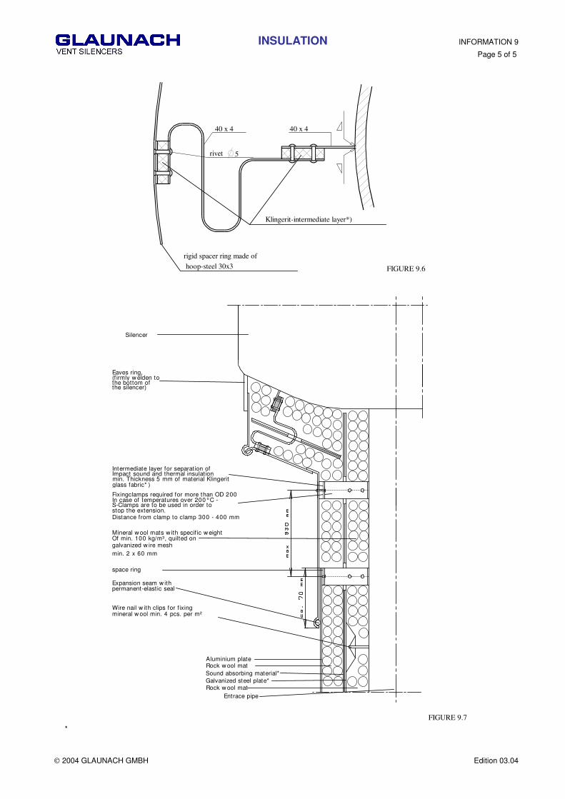
hoop-steel 30x3
rigid spacer ring made of
Klingerit-intermediate layer*)
rivet 5
40 x 4 40 x 4
FIGURE 9.6
Eaves ring,(f irmly w elden tothe bottom ofthe silencer)
Silencer
Intermediate layer for separation ofImpact sound and thermal insulationmin. Thickness 5 mm of material Klingerit
Fixingclamps required for more than OD 200In case of temperatures over 200°C -S-Clamps are to be used in order tostop the extension.Distance from clamp to clamp 300 - 400 mm
Mineral w ool mats w ith specif ic w eightOf min. 100 kg/m³, quilted ongalvanized w ire mesh
space ring
Expansion seam w ithpermanent-elastic seal
Wire nail w ith clips for f ixingmineral w ool min. 4 pcs. per m²
Aluminium plateRock w ool matSound absorbing material*Galvanized steel plate*Rock w ool mat
min. 2 x 60 mm
Entrace pipe
glass fabric* )
FIGURE 9.7
*
HEATING INFORMATION 10
Page 1 of 1
2004 GLAUNACH GMBH Edition 03.04
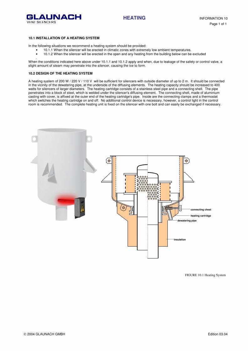
10.1 INSTALLATION OF A HEATING SYSTEM In the following situations we recommend a heating system should be provided:
• 10.1.1 When the silencer will be erected in climatic zones with extremely low ambient temperatures. • 10.1.2 When the silencer will be erected in the open and any heating from the building below can be excluded .
When the conditions indicated here above under 10.1.1 and 10.1.2 apply and when, due to leakage of the safety or control valve, a slight amount of steam may penetrate into the silencer, causing the ice to form. 10.2 DESIGN OF THE HEATING SYSTEM A heating system of 200 W / 220 V / 110 V will be sufficient for silencers with outside diameter of up to 2 m. It should be connected in the vicinity of the dewatering pipe, at the underside of the diffusing elements. The heating capacity should be increased to 400 watts for silencers of larger diameters. The heating cartridge consists of a stainless steel pipe and a connecting shell. The pipe penetrates into a block of steel, which is welded under the silencer's diffusing element. The connecting shell, made of aluminium casting with cover, is affixed at the outer end of the heating cartridge's pipe. Inside are the connecting clamps and a thermostat which switches the heating cartridge on and off. No additional control device is necessary, however, a control light in the control room is recommended. The complete heating unit is fixed on the silencer with one bolt and can easily be exchanged if necessary.
FIGURE 10.1 Heating System
heating cartridge
connecting chest
dewatering pipe
insulation
AVOIDANCE OF FAULTS INFORMATION 11
Page 1 of 6
2004 GLAUNACH GMBH Edition 03.04
11.1 GENERAL INFORMATION
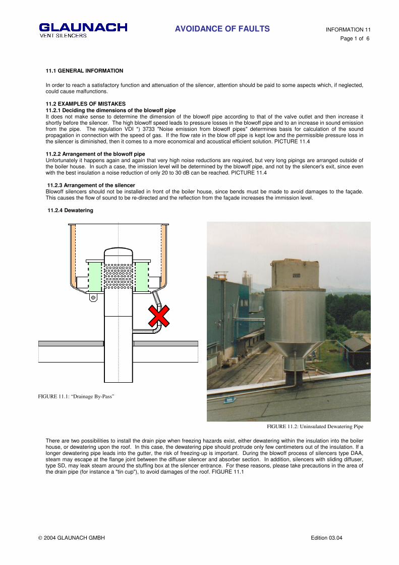
In order to reach a satisfactory function and attenuation of the silencer, attention should be paid to some aspects which, if neglected, could cause malfunctions. 11.2 EXAMPLES OF MISTAKES 11.2.1 Deciding the dimensions of the blowoff pipe It does not make sense to determine the dimension of the blowoff pipe according to that of the valve outlet and then increase it shortly before the silencer. The high blowoff speed leads to pressure losses in the blowoff pipe and to an increase in sound emission from the pipe. The regulation VDI *) 3733 "Noise emission from blowoff pipes" determines basis for calculation of the sound propagation in connection with the speed of gas. If the flow rate in the blow off pipe is kept low and the permissible pressure loss in the silencer is diminished, then it comes to a more economical and acoustical efficient solution. PICTURE 11.4 11.2.2 Arrangement of the blowoff pipe Unfortunately it happens again and again that very high noise reductions are required, but very long pipings are arranged outside of the boiler house. In such a case, the imission level will be determined by the blowoff pipe, and not by the silencer's exit, since even with the best insulation a noise reduction of only 20 to 30 dB can be reached. PICTURE 11.4 11.2.3 Arrangement of the silencer Blowoff silencers should not be installed in front of the boiler house, since bends must be made to avoid damages to the façade. This causes the flow of sound to be re-directed and the reflection from the façade increases the immission level. 11.2.4 Dewatering
FIGURE 11.1: “Drainage By-Pass”
FIGURE 11.2: Uninsulated Dewatering Pipe
There are two possibilities to install the drain pipe when freezing hazards exist, either dewatering within the insulation into the boiler house, or dewatering upon the roof. In this case, the dewatering pipe should protrude only few centimeters out of the insulation. If a longer dewatering pipe leads into the gutter, the risk of freezing-up is important. During the blowoff process of silencers type DAA, steam may escape at the flange joint between the diffuser silencer and absorber section. In addition, silencers with sliding diffuser, type SD, may leak steam around the stuffing box at the silencer entrance. For these reasons, please take precautions in the area of the drain pipe (for instance a "tin cup"), to avoid damages of the roof. FIGURE 11.1

AVOIDANCE OF FAULTS INFORMATION 11
Page 2 of 6
2004 GLAUNACH GMBH Edition 03.04
11.2.5 Silencer with Sliding Diffuser
Please Note: silencers with sliding diffuser can only take up a vertical elongation. Horizontal elongation can lead to wedging, and/or leakage of the sliding diffuser. Therefore it is necessary to provide a vertical guidance prior to the sliding diffuser to prevent horizontal length elongations by suitable precautions (see figure 7.1).
FIGURE 11.3: Sliding Diffuser are for vertical expansion only
AVOIDANCE OF FAULTS INFORMATION 11
Page 3 of 6
2004 GLAUNACH GMBH Edition 03.04
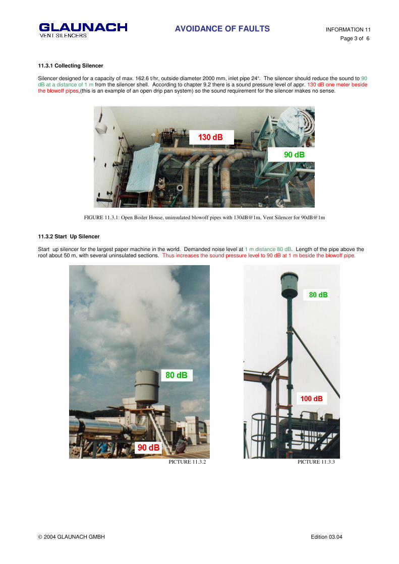
11.3.1 Collecting Silencer Silencer designed for a capacity of max. 162.6 t/hr, outside diameter 2000 mm, inlet pipe 24“. The silencer should reduce the sound to 90 dB at a distance of 1 m from the silencer shell. According to chapter 9.2 there is a sound pressure level of appr. 130 dB one meter beside the blowoff pipes,(this is an example of an open drip pan system) so the sound requirement for the silencer makes no sense.
FIGURE 11.3.1: Open Boiler House, uninsulated blowoff pipes with 130dB@1m, Vent Silencer for 90dB@1m
11.3.2 Start Up Silencer Start up silencer for the largest paper machine in the world. Demanded noise level at 1 m distance 80 dB. Length of the pipe above the roof about 50 m, with several uninsulated sections. Thus increases the sound pressure level to 90 dB at 1 m beside the blowoff pipe.
PICTURE 11.3.2 PICTURE 11.3.3

AVOIDANCE OF FAULTS INFORMATION 11
Page 4 of 6
2004 GLAUNACH GMBH Edition 03.04
11.3 START UP SILENCER (by other manufacturers)
FIGURE 11.3.1
The steam jet hit the head of the diffuser with sonic speed and high temperature that destroyed it immediately. PICTURE 11.3.2 A part of the head plate destroyed the core of the absorber and blew it away. PICTURE 11.3.3. The silencer was useless immediately and a danger for the environment. The diffuser cage and absorber was removed and replaced by a Glaunach Diffuser. Now the silencer works without any problems. This picture is an example of an extremely poor diffuser design still used by many companies today.
PICTURE 11.3.2
PICTURE 11.3.3

AVOIDANCE OF FAULTS INFORMATION 11
Page 5 of 6
2004 GLAUNACH GMBH Edition 03.04
Installation of the Glaunach Diffuser. into existing shell PICTURE 11.3.4 and 11.3.5
PICTURE 11.3.4 PICTURE 11.3.5
View on the heat recovery boiler with repaired silencers.
GLAUNACH Diffuser Design
PICTURE 11.3.6

AVOIDANCE OF FAULTS INFORMATION 11
Page 6 of 6
2004 GLAUNACH GMBH Edition 03.04
12 RENTAL SILENCER 12.1 General When new boilers are built or repair work is carried out, the piping system is contaminated. All impurities must be removed before gas or steam is used in a process. They are removed by “blowing free“ the piping. Silencers used for reducing the emerging noise do not withstand the continuous stress or become ineffective as a result of the contamination. Glaunach has developed a special silencer which can be used repeatedly. The diffuser cartridge of this silencer can be changed if – in consequence of the impurities – the back pressure becomes too high. 12.2 Mode of operation There are radial diffuser borings under the diffuser cartridge of the blow off pipe (1), which reduce the set pressure to atmospheric pressure. The number of diffuser borings and thus the free area is shown below. The upper cover plate of the cartridge (2) is suppressed by a bolted flange ring. After removing the flange ring the diffuser cartridge can be changed. The diffuser cartridge consists of a stable welding construction, the inner and outer side of the absorption filling is covered with a perforated plate cylinder. If too much dust comes into the diffuser cartridge, the pressure drop in the diffuser increases. As pressure increases in the blow-off pipe (1), steam conditions change and speed decreases. That is why the back pressure in the blow-off pipe must be supervised by means of a ½“ measuring connection supplied to the inlet pipe. For each application the rental silencer is equipped with a new cartridge. One additional replacement cartridge is supplied, so that it can be changed if there is an increase in pressure during the blow-off process. Thanks to the compact and stable method of construction this silencer has an infinite life so that we are able to continue providing it for different blow-off processes. If a high noise reduction is required during blow-off (e.g. blow-off in residential areas), the rental silencer can be provided with an additional absorber. 12.3 Design data:
Rental silencer without absorber with absorber Design pressure: 16 bar (g) Design temperature: 480° C Noise reduction: approx. 50 dB approx. 70 dB Diameter of the diffuser borings 3 mm Number of the diffuser borings 20.832 Free area 0,1472 m²
Table 12.1: Design Data The free surface can be reduced but not enlarged, the capacity of the rental silencer is therefore limited. 12.4. Weights and dimensions:
weight [kg] L x B x H [m] Silencer incl. changeable diffuser cartridge 1050 2,2x2,2x2,2 Silencer with absorbing and changeable diffuser cartridge 2060 3,6x2,2x2,4 Absorber 1010 2,0x1,2x2,4 Changeable diffuser cartridge 400 1,3x1,3x1,0
Table 12.2 : Weights & Dimensions
RENTAL SILENCER INFORMATION 12
Page 1 of 1
2004 GLAUNACH GMBH Edition 03.04
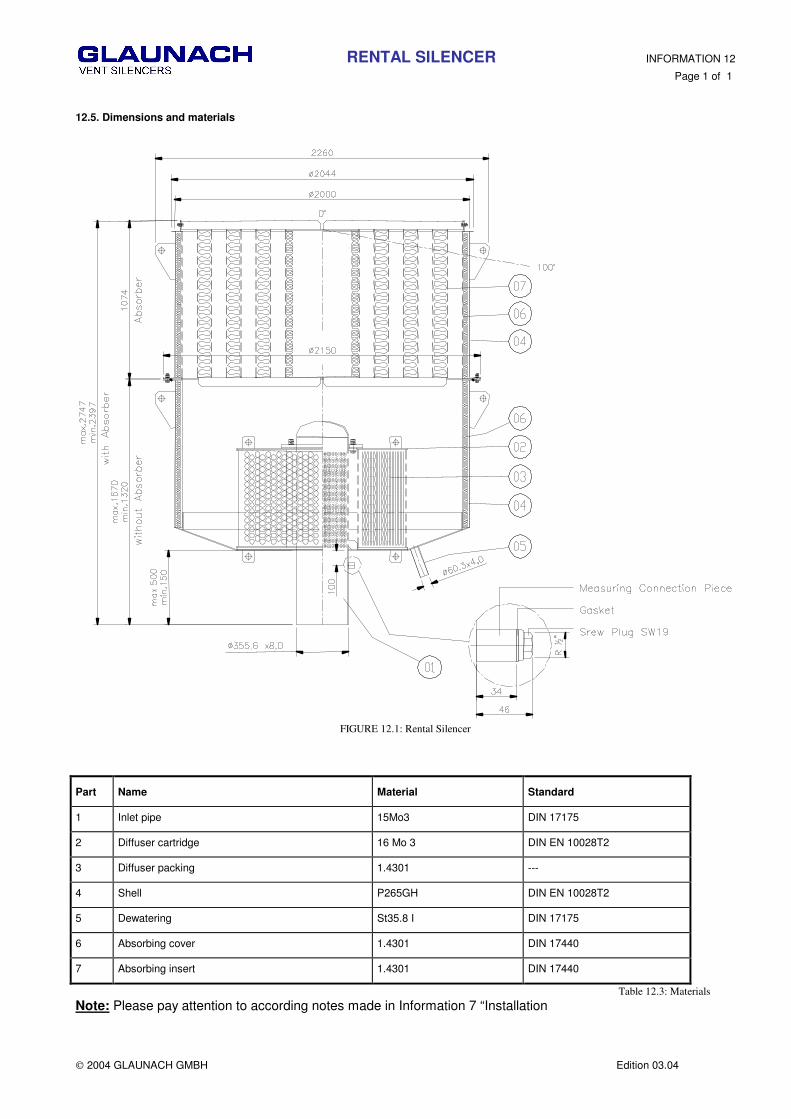
12.5. Dimensions and materials
FIGURE 12.1: Rental Silencer
Part Name Material Standard
1 Inlet pipe 15Mo3 DIN 17175
2 Diffuser cartridge 16 Mo 3 DIN EN 10028T2
3 Diffuser packing 1.4301 ---
4 Shell P265GH DIN EN 10028T2
5 Dewatering St35.8 I DIN 17175
6 Absorbing cover 1.4301 DIN 17440
7 Absorbing insert 1.4301 DIN 17440
Table 12.3: Materials Note: Please pay attention to according notes made in Information 7 “Installation

MAIN CONTRACTORS INFORMATION 13 Page 1 of 2
2004 GLAUNACH GMBH Edition 04.04
AALBORG BOILERS AS Aalborg Denmark
ABB CARBON AB Västerås Sweden
ABB ENERTECH AG Winterthur Switzerland
ADVANCED VALVES SOLUTIONS BV Heerhugowaard Netherlands
AHLSTRÕM CORPORATION Kaarina Finland
ALSTOM ENERGY SYSTEMS GMBH Kassel Germany
ALSTOM POWER AG Baden Switzerland
ALSTOM POWER INC Windsor, CT USA
ALSTOM Power LTD North Ryde Australia
ANSALDO COMPONENTI Legnano Italy
APEX SCIENCE & ENG CO Taipei Taiwan
AUSTRIAN ENERGY & ENVIRONMENT Vienna/Graz/Linz Austria
BABCOCK BORSIG POWER ENERGY GMBH Oberhausen Germany
BERTSCH GMBH Bludenz Austria
BOPP & REUTHER Vienna Austria
BURMEISTER & WAIN ENERGI A/S Virum Denmark
COMPRIMO ENGINEERING & CONTR Amsterdam Netherlands
CTCI CORPORATION Taipei Taiwan
DUMAS VERFAHRENSTECHNIK GMBH Hofheim Germany
DURO DAKOVIC DD Slavonski Brod Croatia
DOOSAN Busan Korea
EISENWERK BAUMGARTE Bielefeld Germany
EKONO OY Helsinki Finland
ELIN ENERGIEVERSORGUNG Vienna Austria
ELECTRICITY SUPPLY BOARD Dublin Ireland
ENEL SOZIETÁ PER AZONI Rome Italy
FAGERBERG GUSTAV AS Brondby Denmark
FISHER ROSEMOUNT Pty, LTD Singapore Singapore
FORTUM ENGENEERING LTD Fortum Finland
FOSTER WHEELER Helsinki Finland
GEC-ALSTHOM Paris France
GÖTAVERKEN ENERGY AB Gothenburg Sweden
HANJUNG Changwon Korea
HANKUK SYSTEM Co, LTD Seoul Korea
HYUNDAI MIPO DOCKYARD CO LTD Ulsan Korea
ING BONO SpA Peschiera/Borromeo Italy

MAIN CONTRACTORS INFORMATION 13 Page 2 of 2
2004 GLAUNACH GMBH Edition 04.04
ISHIKAWAJIMA NOISE CONTROL Co Tokyo Japan
IVO POWER ENGENEERING LTD Ivo Finnland
JOHN BROWN ENGINEERS & CONSTR LTD Zoetermeer Netherlands
KENNEDY & DONKIN Bristol Great Britain
KAWASAKI HEAVY INDUSTRIES Osaka Japan
KINETICS TECHNOLOGY INTERN BV Zoetermeer Netherlands
KRAFTANLAGEN ANLAGENTECHNIK München Germany
KRUPP KOPPERS Essen Germany
KRUPP UHDE GMBH Dortmund Germany
KVAERNER PULPING Tampere Finland
KYOKUTO BOEKI KAISHA LTD Tokyo Japan
LAHMEYER INTERNATIONAL Frankfurt Germany
LENTJES AG Düsseldorf Germany
LURGI ENVIROTHERM GMBH Frankfurt Germany
MANNESMANN ANLAGENBAU Vienna Austria
MITSUBISHI HEAVY INDUSTRIES LTD Tokyo Japan
NOOTER ERIKSEN St Louis, MO USA
OSCHATZ GMBH Essen Germany
PUBLIC POWER CORPORATION Athen Greece
SA KLINGER MARCHAL NV Bruxelles Belgium
SALZGITTER LUMMUS GMBH Salzgitter Germany
SAMSUNG ENGINEERING CO LTD Seoul Korea
SIEMENS AG / KWU Erlangen Germany
SPECTRIS COMPONENTS GMBH Vienna Austria
STANDARD FASEL LENTJES BV Utrecht Netherlands
STORK ENERGY Hengelo Netherlands
STORK KETELS INDONESIA Bekasi Indonesia
TECHNIP GERMANY GMBH Stuttgart Germany
TECHNOPROMEXPORT Moscow Russia
VON ROLL AG Zürich Switzerland
YIEH HSING ENTERPRISE CO Kaohsiung Hsien Taiwan