giga-pixel lensfree holographic microscopy and tomography ... · state-of-the-art sensor-arrays...
TRANSCRIPT
Giga-Pixel Lensfree Holographic Microscopy andTomography Using Color Image SensorsSerhan O. Isikman1., Alon Greenbaum1., Wei Luo1., Ahmet F. Coskun1, Aydogan Ozcan1,2,3,4*
1 Electrical Engineering Department, University of California Los Angeles, Los Angeles, California, United States of America, 2 Bioengineering Department, University of
California Los Angeles, Los Angeles, California, United States of America, 3California NanoSystems Institute, University of California Los Angeles, Los Angeles, California,
United States of America, 4Department of Surgery, School of Medicine, University of California Los Angeles, Los Angeles, California, United States of America
Abstract
We report Giga-pixel lensfree holographic microscopy and tomography using color sensor-arrays such as CMOS imagersthat exhibit Bayer color filter patterns. Without physically removing these color filters coated on the sensor chip, wesynthesize pixel super-resolved lensfree holograms, which are then reconstructed to achieve ,350 nm lateral resolution,corresponding to a numerical aperture of ,0.8, across a field-of-view of ,20.5 mm2. This constitutes a digital image with,0.7 Billion effective pixels in both amplitude and phase channels (i.e., ,1.4 Giga-pixels total). Furthermore, by changingthe illumination angle (e.g.,650u) and scanning a partially-coherent light source across two orthogonal axes, super-resolvedimages of the same specimen from different viewing angles are created, which are then digitally combined to synthesizetomographic images of the object. Using this dual-axis lensfree tomographic imager running on a color sensor-chip, weachieve a 3D spatial resolution of ,0.35 mm60.35 mm6,2 mm, in x, y and z, respectively, creating an effective voxel size of,0.03 mm3 across a sample volume of ,5 mm3, which is equivalent to .150 Billion voxels. We demonstrate the proof-of-concept of this lensfree optical tomographic microscopy platform on a color CMOS image sensor by creating tomograms ofmicro-particles as well as a wild-type C. elegans nematode.
Citation: Isikman SO, Greenbaum A, Luo W, Coskun AF, Ozcan A (2012) Giga-Pixel Lensfree Holographic Microscopy and Tomography Using Color ImageSensors. PLoS ONE 7(9): e45044. doi:10.1371/journal.pone.0045044
Editor: Ge Wang, Virginia Tech, United States of America
Received June 20, 2012; Accepted August 11, 2012; Published September 12, 2012
Copyright: � 2012 Isikman et al. This is an open-access article distributed under the terms of the Creative Commons Attribution License, which permitsunrestricted use, distribution, and reproduction in any medium, provided the original author and source are credited.
Funding: A. Ozcan gratefully acknowledges the support of the Presidential Early Career Award for Scientists and Engineers (PECASE), ARO Young InvestigatorAward, National Science Foundation (NSF) CAREER Award, the Office of Naval Research Young Investigator Award 2009 and the National Institutes of Health (NIH)Director’s New Innovator Award DP2OD006427 from the Office of The Director, NIH. The authors also acknowledge the support of the NSF BISH program (underAwards # 0754880 and 0930501). The funders had no role in study design, data collection and analysis, decision to publish, or preparation of the manuscript.
Competing Interests: A. Ozcan is the founder of a start-up company (Holomic LLC, based in Los Angeles) that is aiming to commercialize computationalmicroscopy. A. Ozcan also serves as a part-time consultant to Holomic LLC. This does not alter the authors’ adherence to all the PLoS ONE policies on sharing dataand materials.
* E-mail: [email protected]
. These authors contributed equally to this work.
Introduction
Color opto-electronic sensors such as CMOS imagers that
exhibit Bayer patterns (composed of one Red, two Green and one
Blue pixels) form the main stream detector-arrays employed in
digital electronic devices, including cell phones, webcams and
digital cameras, with a sales volume of .5 billion per year [1]. The
use of such cost-effective yet powerful imaging components has
been an emerging theme for various applications including point-
of-care microscopy and sensing [2–8]. Along the same lines,
lensfree computational imaging techniques [9–25] also demand
state-of-the-art sensor-arrays that employ smaller pixel sizes as well
as larger pixel counts (for increased imaging field-of-view). By
making use of such advanced image sensors, lensfree microscopy
can provide sub-micron spatial resolution over large imaging
areas, within a rather compact and cost-effective design, which is
particularly suitable for telemedicine needs and lab-on-a-chip
platforms. While consumer electronics has been the driving
motivation to create such sensor chips [26], an important obstacle
for lensfree holographic imaging has been the Bayer filter pattern
(i.e., Red, Green and Blue filters) installed on color sensor-chips.
Since holographic microscopy techniques typically employ quasi-
monochromatic light sources [12–23,27–36] (with spectral band-
widths of ,1–30 nm), the pixels coated with different color filters
respond differently to incident light. As a result, the Bayer color
filter pattern installed on the imaging area can introduce undesired
artefacts. While color sensors have been successfully employed in
phase-shifting digital holography schemes to achieve color imaging
with multiple lasers [27], such sensors unfortunately create
artefacts in lensfree on-chip holography, particularly impeding
the use of pixel super-resolution algorithms [19,20,37,38]. This
problem can potentially be mitigated by e.g., physical removal of
such color filters placed above the active region of each pixel.
While feasible, physical removal of such color filters is costly to
implement in high-volumes, and could alter the optimized design
of pixel structures. Another option is to use monochrome version
of the same sensor-chip of interest, which, however, is not often
released by CMOS manufacturers since the main application
areas, i.e., cell phones, and webcams, strictly demand color sensor-
arrays. To better handle this challenge, here we introduce a new
computational approach to utilize color sensor-arrays in lensfree
microscopy and tomography for achieving Giga-pixel imaging on
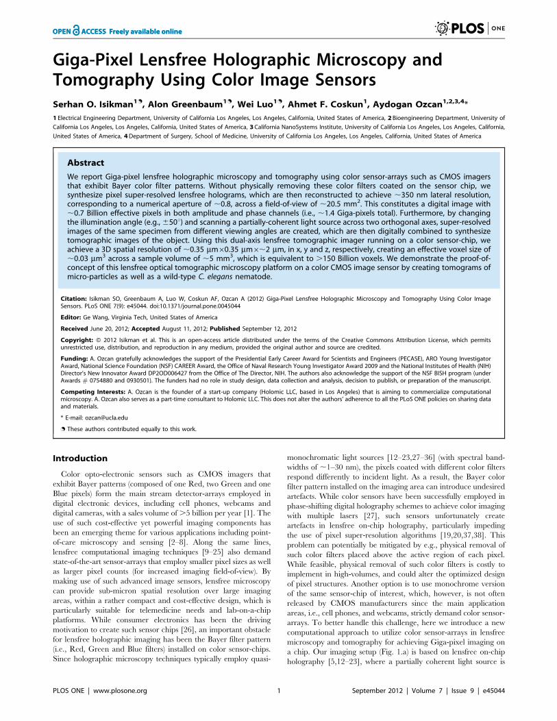
a chip. Our imaging setup (Fig. 1.a) is based on lensfree on-chip
holography [5,12–23], where a partially coherent light source is
PLOS ONE | www.plosone.org 1 September 2012 | Volume 7 | Issue 9 | e45044
used to illuminate a sample that is placed on the top of a sensor
array, to record digital in-line holograms of objects with unit fringe
magnification over a large field-of-view (see the Methods section).
In this work, we specifically employed a color CMOS sensor chip
(Fig. 1.b) that has a pixel size of 1.12 mm and an active area of
20.5 mm2. Without physically removing the color filters installed
on a sensor chip, based on a new reconstruction approach, as
illustrated in Fig. 2, we synthesize pixel super-resolved lensfree
holograms of specimen using 45u rotated green pixel functions
(refer to Methods Section for details). These super-resolved
holograms are then reconstructed to achieve ,350 nm lateral
resolution, corresponding to a numerical aperture (NA) of ,0.8,
across a field-of-view of ,20.5 mm2. This constitutes a lensfree
digital image with ,0.7 Giga-pixels effectively, in both amplitude
and phase channels, i.e., ,1.4 Giga-pixels in total. It should also
be noted that the use of oil immersion techniques [39] can further
improve the lateral resolution, permitting numerical apertures
reaching up to e.g., ,0.9, as recently demonstrated in our work
[40]. In addition, by changing the illumination angle over 650
degrees, pixel super-resolved images of the same object from
different viewing angles can be created and digitally combined to
form lensfree tomograms of the object (see Methods Section)
[23,41]. The architectural simplicity of this platform also permits
scanning the light source across two orthogonal axes to obtain
additional perspective images of the sample, and further improve
tomographic imaging quality. With this dual-axis lensfree tomo-
graphic imager running on a color CMOS chip, we achieved
a spatial resolution of ,0.35 mm60.35 mm6,2 mm, in the x, y
and z directions, respectively. These results create an effective
voxel size of ,0.03 mm3 across a sample volume of ,5 mm3,
which is equivalent to .150 Billion voxels.
Compared to our earlier lensfree on-chip tomography platform
[23], which utilized relatively older generation monochrome
sensor-chips, these current results constitute more than an order of
magnitude increase in our voxel density, significantly improving
the 3D space-bandwidth product of our lensfree imaging platform.
We validated the performance of this on-chip tomographic
microscope by imaging micro-particles and a wild-type C. elegans
nematode.
Results
To quantify the lateral resolution of our lensfree holographic
set-up based on color CMOS sensor-arrays and validate our
modified pixel super-resolution method (Fig. 2), we imaged
a grating with 350 nm lines etched on glass (i.e., 700 nm period),
which was fabricated using focused ion beam (FIB) milling. Fig 3.a
shows the raw lensfree hologram of the grating, cropped from
a large FOV (,20.5 mm2). The first diffraction order can be seen
in the holographic image; although, the fringes for this order could
not be resolved due to spatial under-sampling. The zoomed inset
(top image) in Fig. 3.a also illustrates the presence of the Bayer
pattern artefact in this image.
Based on our modified pixel-super resolution approach (see the
Methods Section and Fig. 2), both the Bayer pattern of the color
sensor-array and the under-sampling related artefacts were
mitigated using 64 (868 grid) sub-pixel shifted lower-resolution
in-line holograms (see Fig. 3.b). Consequently, the grating object
with a half-period of 350 nm could be reconstructed, as shown in
Fig. 3.c. A conventional bright-field microscope image (606, 0.85-
NA) of the same grating is also provided for comparison (Fig. 3.d).
This result demonstrates the lateral resolving power of our lensfree
Figure 1. Giga-Pixel Lensfree Holographic Microscopy and Tomography setup. (a) Shows a multi-exposure photograph of the lensfreeoptical tomography setup employing a colour image sensor. An optical fibre attached to a rotation stage delivers partially-coherent light to thesample, placed on the sensor, at different angles. The light source is also translated laterally using scanning stages to perform pixel super-resolutionat each illumination angle. (b) Shows the photograph of the colour image sensor chip. The protective glass, colour filters and the microlens-array onthe active area of the sensor remain intact. (c) Shows a cropped lensfree hologram image to demonstrate the Bayer colour filter pattern.doi:10.1371/journal.pone.0045044.g001
Giga-Pixel Holographic Microscopy and Tomography
PLOS ONE | www.plosone.org 2 September 2012 | Volume 7 | Issue 9 | e45044
on-chip microscopy system based on a color CMOS imager,
achieving a numerical aperture (NA) of ,0.8.
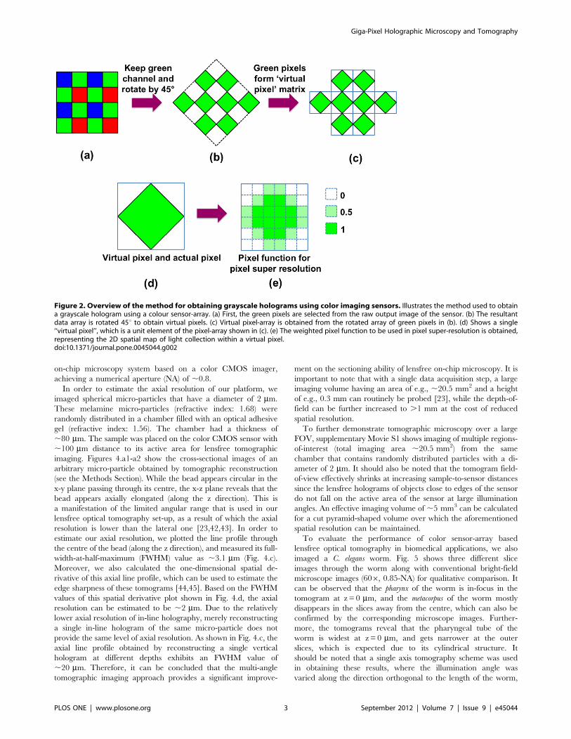
In order to estimate the axial resolution of our platform, we
imaged spherical micro-particles that have a diameter of 2 mm.
These melamine micro-particles (refractive index: 1.68) were
randomly distributed in a chamber filled with an optical adhesive
gel (refractive index: 1.56). The chamber had a thickness of
,80 mm. The sample was placed on the color CMOS sensor with
,100 mm distance to its active area for lensfree tomographic
imaging. Figures 4.a1-a2 show the cross-sectional images of an
arbitrary micro-particle obtained by tomographic reconstruction
(see the Methods Section). While the bead appears circular in the
x-y plane passing through its centre, the x-z plane reveals that the
bead appears axially elongated (along the z direction). This is
a manifestation of the limited angular range that is used in our
lensfree optical tomography set-up, as a result of which the axial
resolution is lower than the lateral one [23,42,43]. In order to
estimate our axial resolution, we plotted the line profile through
the centre of the bead (along the z direction), and measured its full-
width-at-half-maximum (FWHM) value as ,3.1 mm (Fig. 4.c).
Moreover, we also calculated the one-dimensional spatial de-
rivative of this axial line profile, which can be used to estimate the
edge sharpness of these tomograms [44,45]. Based on the FWHM
values of this spatial derivative plot shown in Fig. 4.d, the axial
resolution can be estimated to be ,2 mm. Due to the relatively
lower axial resolution of in-line holography, merely reconstructing
a single in-line hologram of the same micro-particle does not
provide the same level of axial resolution. As shown in Fig. 4.c, the
axial line profile obtained by reconstructing a single vertical
hologram at different depths exhibits an FWHM value of
,20 mm. Therefore, it can be concluded that the multi-angle
tomographic imaging approach provides a significant improve-
ment on the sectioning ability of lensfree on-chip microscopy. It is
important to note that with a single data acquisition step, a large
imaging volume having an area of e.g., ,20.5 mm2 and a height
of e.g., 0.3 mm can routinely be probed [23], while the depth-of-
field can be further increased to .1 mm at the cost of reduced
spatial resolution.
To further demonstrate tomographic microscopy over a large
FOV, supplementary Movie S1 shows imaging of multiple regions-
of-interest (total imaging area ,20.5 mm2) from the same
chamber that contains randomly distributed particles with a di-
ameter of 2 mm. It should also be noted that the tomogram field-
of-view effectively shrinks at increasing sample-to-sensor distances
since the lensfree holograms of objects close to edges of the sensor
do not fall on the active area of the sensor at large illumination
angles. An effective imaging volume of ,5 mm3 can be calculated
for a cut pyramid-shaped volume over which the aforementioned
spatial resolution can be maintained.
To evaluate the performance of color sensor-array based
lensfree optical tomography in biomedical applications, we also
imaged a C. elegans worm. Fig. 5 shows three different slice
images through the worm along with conventional bright-field
microscope images (606, 0.85-NA) for qualitative comparison. It
can be observed that the pharynx of the worm is in-focus in the
tomogram at z = 0 mm, and the metacorpus of the worm mostly
disappears in the slices away from the centre, which can also be
confirmed by the corresponding microscope images. Further-
more, the tomograms reveal that the pharyngeal tube of the
worm is widest at z = 0 mm, and gets narrower at the outer
slices, which is expected due to its cylindrical structure. It
should be noted that a single axis tomography scheme was used
in obtaining these results, where the illumination angle was
varied along the direction orthogonal to the length of the worm,
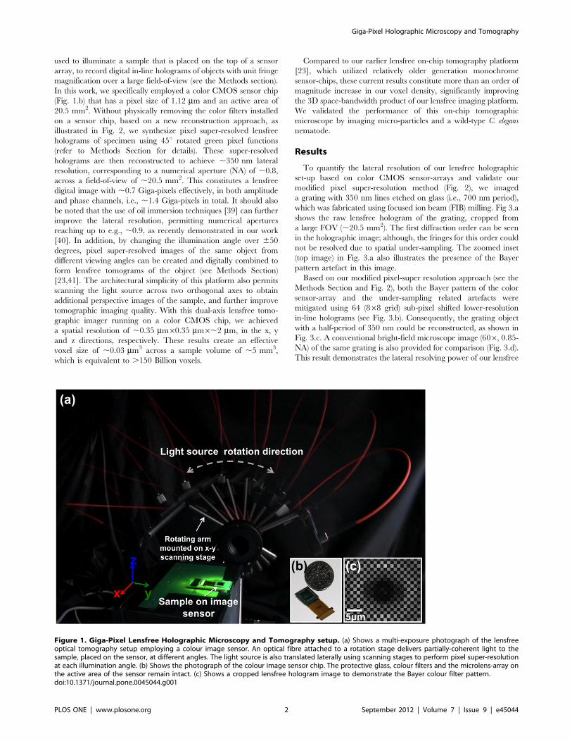
Figure 2. Overview of the method for obtaining grayscale holograms using color imaging sensors. Illustrates the method used to obtaina grayscale hologram using a colour sensor-array. (a) First, the green pixels are selected from the raw output image of the sensor. (b) The resultantdata array is rotated 45u to obtain virtual pixels. (c) Virtual pixel-array is obtained from the rotated array of green pixels in (b). (d) Shows a single‘‘virtual pixel’’, which is a unit element of the pixel-array shown in (c). (e) The weighted pixel function to be used in pixel super-resolution is obtained,representing the 2D spatial map of light collection within a virtual pixel.doi:10.1371/journal.pone.0045044.g002
Giga-Pixel Holographic Microscopy and Tomography
PLOS ONE | www.plosone.org 3 September 2012 | Volume 7 | Issue 9 | e45044

since including the other axis would not improve the image
quality due to the elongated shape of the worm [23].
Discussion
Using the state-of-the-art ‘color’ image sensors, lensfree optical
tomography can now achieve Giga-pixel imaging with ,350 nm
lateral resolution (corresponding to an NA of ,0.8) and ,2 mm
axial resolution, which results in an order of magnitude increased
voxel density, i.e., space-bandwidth product, compared to what
was previously achieved for on-chip tomography [23]. Owing to its
large imaging area of 20.5 mm2 and long depth-of-field (DOF) of
,0.3 mm, a large sample volume of ,5 mm3 can be probed with
.150 Billion voxels, which can be useful for wide-field imaging
applications in lab-on-a-chip platforms. Here, we should also
emphasize that Giga-pixel microscopy in the context of lensfree
on-chip imaging refers to the effective number of digital pixels in the
reconstructed image, with the assumption that 2 pixels define the
minimum resolvable feature size. In this scheme, pixel super-
resolution techniques permit achieving Giga-pixel imaging, which
is different than the recent Giga-pixel photography work [46].
The use of a color sensor-array is an important step forward in
lensfree holographic on-chip imaging. The rapid advances in
imaging sensors are mainly driven by consumer electronics
industry toward developing higher-resolution color sensor chips
with larger active areas. Therefore, their incorporation in lensfree
on-chip imaging platforms is critical such that off-the-shelf sensors
can be cost-effectively integrated with compact lensfree micro-
scopes to achieve immediate enhancement of image quality as
better sensors become available. The results presented in this work
demonstrate this trend, where an order of magnitude improve-
ment in space-bandwidth product is achieved using a color CMOS
imager and a modified pixel super-resolution algorithm that
overcomes the limitations posed by the Bayer filters installed on
sensor chips. It is important to note that even though our
experimental results are obtained using the green pixels only, the
illumination wavelength is not restricted to only ,530 nm, as the
spectral response of the green color filters is rather broad (i.e.,
FWHM ,115 nm). Therefore using different illumination wave-
lengths is also possible, without any modification to the presented
image processing technique or the experimental set-up.
The ability to image a large DOF is another important
advantage that significantly enhances the imaging throughput.
The key enabler for this is the in-line holographic recording
scheme that permits digital focusing to an arbitrary depth of
interest. Although the highest resolution is achieved when the
sample-to-sensor distance is ,0.3 mm, an extended DOF of e.g.,
4–5 mm can be imaged at the cost of reduced spatial resolution
due to lower detection SNR at increased heights above the sensor.
It is important to note, however, that this extended DOF does not
correspond to the thickness of a continuous sample that can be
axially sectioned. For lensfree optical tomography to provide
a decent image quality, the reconstructed images should represent
projections, i.e. line integrals along the illumination direction, of
a certain property of the object such as its phase, absorption or
scattering potential functions. Currently, we use the amplitude of
the reconstructed lensfree images, with the assumption that they
represent the projections of the scattering strength of the object.
The quality of reconstructions depends on the validity of this
assumption. Thick objects, e.g. .50 mm, violate this assumption
Figure 3. Lensfree imaging results demonstrating 0.35 mm half-pitch lateral resolution. (a) Shows a cropped raw lensfree hologram ofa grating structure etched on glass. The fringes on the first diffraction order (indicated by the arrow) cannot be resolved due to under-sampling. (b)Shows a pixel super-resolved (SR) hologram of the same grating. The fringes on the first diffraction order are now resolved. (c) Shows the lensfreeimage obtained by reconstructing the SR hologram, demonstrating that the grating lines can be clearly resolved. (d) Shows a bright-field microscopeimage (606, 0.85-NA) of the same grating for visual comparison. Note that the contrast in (a) and (b) was enhanced for illustration of fine holographicoscillations.doi:10.1371/journal.pone.0045044.g003
Giga-Pixel Holographic Microscopy and Tomography
PLOS ONE | www.plosone.org 4 September 2012 | Volume 7 | Issue 9 | e45044
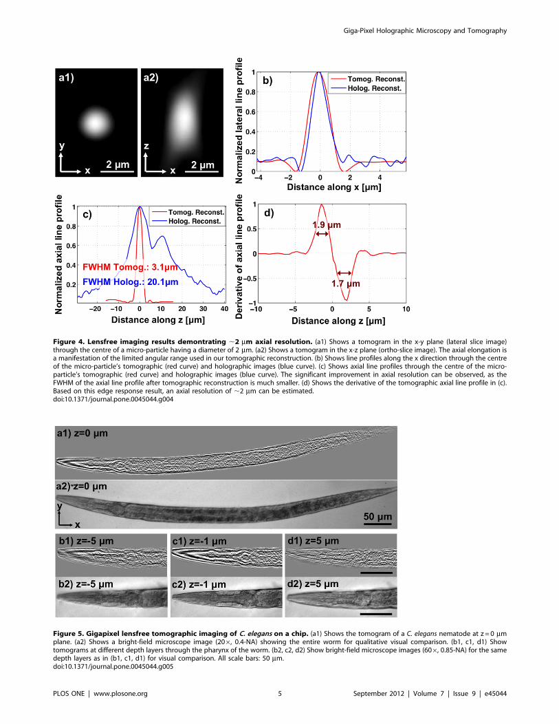
Figure 4. Lensfree imaging results demontrating ,2 mm axial resolution. (a1) Shows a tomogram in the x-y plane (lateral slice image)through the centre of a micro-particle having a diameter of 2 mm. (a2) Shows a tomogram in the x-z plane (ortho-slice image). The axial elongation isa manifestation of the limited angular range used in our tomographic reconstruction. (b) Shows line profiles along the x direction through the centreof the micro-particle’s tomographic (red curve) and holographic images (blue curve). (c) Shows axial line profiles through the centre of the micro-particle’s tomographic (red curve) and holographic images (blue curve). The significant improvement in axial resolution can be observed, as theFWHM of the axial line profile after tomographic reconstruction is much smaller. (d) Shows the derivative of the tomographic axial line profile in (c).Based on this edge response result, an axial resolution of ,2 mm can be estimated.doi:10.1371/journal.pone.0045044.g004
Figure 5. Gigapixel lensfree tomographic imaging of C. elegans on a chip. (a1) Shows the tomogram of a C. elegans nematode at z = 0 mmplane. (a2) Shows a bright-field microscope image (206, 0.4-NA) showing the entire worm for qualitative visual comparison. (b1, c1, d1) Showtomograms at different depth layers through the pharynx of the worm. (b2, c2, d2) Show bright-field microscope images (606, 0.85-NA) for the samedepth layers as in (b1, c1, d1) for visual comparison. All scale bars: 50 mm.doi:10.1371/journal.pone.0045044.g005
Giga-Pixel Holographic Microscopy and Tomography
PLOS ONE | www.plosone.org 5 September 2012 | Volume 7 | Issue 9 | e45044
for two main reasons. First, the depth-of-focus of a reconstructed
image will not be large enough such that all parts of such a thick
object can contribute equally to the reconstructed image, as some
parts of the object will be defocused. This limitation, however, can
be partially mitigated by using a diffraction tomography approach
[45–50], or by reconstructing each in-line hologram at different
depths to estimate the correct weighting factors of slices at various
depths at the cost of increased computational complexity. Second,
and more importantly, thicker samples will strongly scatter the
incoming photons. If light transmission is dominated by multiple
scattering, as is the case when the thickness of the object exceeds
the mean free path of photons through a turbid medium [51],
a line-integral relationship between the reconstructed image and
the structure of the object cannot be maintained. In this case, the
filtered back-projection algorithm (see the Methods Section) will
not provide accurate results and exhibit aberrations. Therefore,
lensfree optical tomography appears to be particularly suitable for
high-throughput imaging of cells and micro-organisms that are
distributed within a thick chamber (e.g. ,1–5 mm), rather than
for imaging thick and optically dense specimen such as tissue
slides. This limitation, however, is common to ‘all’ the existing on-
chip imaging modalities, regardless of their operation principles.
Methods
Lensfree Optical Tomography SetupA partially coherent light source (Xenon lamp attached to
a monochromator), coupled to a multi-mode optical fiber (core
diameter: 105 mm), is attached to a motorized rotation stage,
which is also mounted on a scanning stage (see Fig. 1.a). For
illumination, we used a centre wavelength of 530 nm with
a spectral width of ,3 nm. Although, in the current setup,
3 nm bandwidth was achieved using a monochromator for
experimental flexibility, a light-emitting diode (LED) interfaced
with a simple interference filter could also be utilized. The use of
an interference filter does not significantly increase the cost and
complexity of the system toward field-portable microscopy, since
a filter with a rather small area (e.g. ,1 mm61 mm) placed right
after the LED would be sufficient as demonstrated in our earlier
work [21]. A color CMOS image sensor with a pixel pitch of
1.12 mm is employed (Fig. 1.b). The protective glass, the micro-
lens array and the color filters on the chip remained intact. In this
configuration the sample is placed with typically ,300 mm
distance to the active area. The rotation stage is used to
sequentially illuminate the sample from different angles within
a range of 650u. To achieve pixel super-resolution, multiple sub-
pixel shifted frames are acquired by translating the light source to
different positions using the scanning stage at each illumination
angle. In this set-up, the distance between the light source and the
sensor (z1) is ,8–10 cm, while the distance between the sample
and the image sensor (z2) is typically ,300–500 mm (which can be
increased to .1 mm at the cost of reduced spatial resolution). This
geometry, where z1.. z2, permits recording holograms with unit
fringe magnification [15] and therefore the entire active area of
the sensor (,20.5 mm2) serves as the imaging field-of-view (FOV).
Another important advantage of this geometry is that sub-pixel
hologram shifts of e.g., ,0.1–1 mm at the detector plane can be
achieved by actually shifting the light source by e.g., ,30–300 mm,
which is much easier to achieve without the need for precise
positioning. This is indeed a critical enabler to build compact,
cost-effective and field-portable computational microscopes that
employ pixel super-resolution techniques [20,21]. The intensity
recorded by the sensor-array is a holographically recorded
diffraction pattern of the objects, arising from the interference of
the un-scattered portion of illumination (reference wave) with the
light scattered by the objects (object wave).
The Bayer pattern artefact is clearly observed in the raw images
due to the wavelength selectivity of the color filters on the sensor-
chip (see e.g., Fig. 1.c). Even if a monochrome sensor was used and
full spatial information was retrieved without the Bayer pattern
artefact, the recorded lensfree holograms would still be under-
sampled due to finite pixel size and the unit-magnification.
Therefore, a modified pixel super-resolution algorithm optimized
for color sensor-arrays is a critical step to i) remove the Bayer
pattern artefact; and ii) achieve high-resolution (e.g., ,350 nm)
lensfree imaging beyond what is permitted by the pixel size, that is,
the sampling period of the CMOS sensor array.
Achieving Pixel Super-resolution in Lensfree On-chipHolography using Color Sensors
To solve the under-sampling problem of in-line holograms
captured at unit fringe-magnification, we previously utilized pixel
super-resolution techniques [19,20,37,38]. This approach had to
be modified for color sensors. Using a partially coherent light
source with a centre wavelength of 530 nm, maximum response is
obtained from the pixels coated with green color filters. Hence, for
each unit of the Bayer pattern, only two green channels out of the
four available pixels were processed. The data array from two
green channels per period (Fig. 2.b) was rotated by 45u degrees so
as to obtain a down-sampled hologram ‘without’ interpolating the
pixel values (see Fig. 2.c). This rotation based approach that
eliminates the need for interpolation is rather critical, as
interpolation could alter the measured pixels, especially distorting
the information in the under-sampled regions that are to be
recovered by pixel super-resolution. This down-sampled matrix
can be considered as a monochromatic image captured by a virtual
sensor, as shown in Fig. 2.d, which is rotated by 45u with respect to
the actual image sensor. The virtual pixel size (i.e. the pixel size of
the virtual CMOS sensor) is equal to the diagonal length of the
physical pixels, i.e. ,1.58 mm in our case. To estimate the sub-
pixel shifts between the rotated lower-resolution (LR) images, an
iterative gradient method is utilized [38]. This iterative gradient
method provides accurate shift estimations, which were validated
empirically, even though the rotated pixels are virtual pixels, and
half of the area represented by this virtual image is not physically
captured (see Fig. 2.b). Then, a pixel super-resolved (SR) hologram
is synthesized by optimizing a cost function that minimizes the
difference between the estimated SR hologram and the set of
measured LR holograms [19,20,38]. Through this optimization
process, pixel super-resolution decomposes the larger virtual pixels
of the lower-resolution rotated holograms into effectively much
smaller pixels. Therefore, it is critical to have a correct model for
spatial light-collection of the virtual pixels. This spatial map of light
collection for a virtual pixel is provided to the minimization
problem as a pixel function. By convolving the ‘estimated’ high-
resolution image by this pixel function, then shifting and down
sampling the result, a measurement-like image is obtained, which
is compared to the actual rotated measurements. In our method
that utilizes color sensors, the pixel function was modified to
a weighted diamond shape (see Fig. 2.e). With this weighted
diamond-shaped pixel function, we obtained superior results
compared to using a flat (un-weighted) pixel function.
Digital Reconstruction of Pixel Super-resolved Hologramsto Obtain Lensfree Projection Images
The pixel super-resolved holograms obtained at different
illumination angles are reconstructed using the numerical tech-
Giga-Pixel Holographic Microscopy and Tomography
PLOS ONE | www.plosone.org 6 September 2012 | Volume 7 | Issue 9 | e45044
nique reported in Ref. 23. Accordingly, the SR holograms are first
multiplied by a tilted plane-wave that represents the reference
wave for the corresponding angle of illumination. It is important to
note that the tilt angle of this reconstruction wave is not necessarily
equal to the physical tilt of the light source due to the refraction of
illumination inside the sample chamber. Therefore, the tilt angle,
hrec, should be digitally estimated as hrec = tan21(Ds/z2), where Ds
is the shift of holograms at a given angle compared to their original
position at vertical illumination, and z2 is the distance between the
detector and the object, which is also estimated digitally using
holographic reconstruction. After multiplication by the tilted
reconstruction wave, the complex field at the hologram plane is
propagated back to the object plane using the angular spectrum
approach. In order to remove the twin image noise from the
reconstructed images, an iterative phase recovery algorithm is
evoked. In this algorithm, by iteratively going back-and-forth
between the object and hologram planes, the phase of the
hologram can be estimated, and reconstructing this complex field
provides a refined lensfree image at the corresponding illumination
angle where the twin image noise is suppressed [15].
Tomographic Reconstruction using Lensfree ProjectionImages
By performing pixel super-resolution, followed by iterative
holographic reconstruction for all angles of illumination (650u),a set of 51 lensfree projection images is obtained for each
orthogonal tilt series. Then, filtered back-projection operation is
used to reconstruct 3D images of the sample. To achieve that, we
used TomoJ [52], which is a plug-in for the open-source image
processing software ImageJ. Accordingly, the projection images
are first registered to obtain a common centre-of-rotation using
a two-step cross-correlation based algorithm as described in Ref.
23. These projection images are then exported to TomoJ to
perform filtered back-projection.
Since the response of the pixels drastically decreases at large
angles (e.g. .50–60u), we limited our illumination angles to 650u.Owing to this limited angular range of each tilt series, isotropic
spatial resolution in 3D cannot be achieved. To address this issue
dual-axis tomography can be utilized. If a dual-axis tomography
scheme is utilized, separate tomograms are initially obtained for
each axis. Then, their corresponding tomograms are merged in
the Fourier domain [23,42]. Each single-axis tomogram has
missing spatial frequencies, referred to as the ‘‘missing wedge’’,
due to the limited angular range used in back-projection [43].
Dual-axis tomography utilizes the fact that the missing wedge for
each set of tomograms will be orthogonal to each other, and the
complementary information in these tomograms can reduce the
missing wedge in Fourier domain to a ‘‘missing pyramid’’ [43].
Accordingly, a new 3D frequency space is synthesized by assigning
the average of the two tomograms to spatial frequencies at which
both tomograms have useful data. For frequencies where only one
axis provides useful information, no averaging is performed and
the value of the corresponding axis is assigned to the new
frequency space. An inverse 3D Fourier transformation of the final
spatial frequency spectrum provides improved tomograms, which
have laterally symmetric point-spread functions as well as
improved axial resolution.
Preparation of the C. elegans SampleWild-type C. elegans nematodes cultured in standard Petri dishes
were used in our experiments. A small piece of the culture,
containing many worms, was suspended in DI water in a small
tube. After 10 minutes, most of the worms swim out of the culture
gel into the water. To temporarily immobilize them during image
acquisition, levamisole (Tetramisole Hydrochloride 99%, Sigma
Aldrich) was added to the tube to obtain a 4 mM solution. Then,
5 mL of the solution was sandwiched between standard cover-slips
and placed on the sensor chip for lensfree tomographic imaging.
ConclusionsWe demonstrated lensfree Giga-pixel microscopy and tomog-
raphy using color image sensors. This platform offers a lateral
resolution of ,350 nm (i.e., a numerical aperture of ,0.8) over
a large imaging area of e.g., 20.5 mm2, which is achieved by
implementing pixel super-resolution on holographic images
captured by state-of-the-art color CMOS sensor-arrays. Further,
an axial resolution of ,2 mm is demonstrated, which can be
achieved over a long depth-of-field of ,0.3 mm. These results
correspond to an imaging volume of ,5 mm3 with .150 Billion
voxels. Achieving such a large space-bandwidth product within
a compact architecture, lensfree optical tomography can provide
an important tool for 3D imaging applications in lab-on-a-chip
platforms.
Supporting Information
Movie S1 Lensfree tomographic imaging of micro-particles over a large field-of-view. This video shows
tomographic on-chip imaging of micro-particles over a large
field-of-view.
(MP4)
Author Contributions
Conceived and designed the experiments: SI AG WL AO. Performed the
experiments: SI AG WL AC. Analyzed the data: SI AG WL. Wrote the
paper: SI AG WL AO.
References
1. Lineback R (n.d.) CMOS Image Sensors Regaining Growth Momentum.
Available:http://www.icinsights.com/data/articles/documents/265.pdf.
2. Brady DJ (2009) Optical Imaging and Spectroscopy. Hoboken, NJ, USA: John
Wiley & Sons, Inc. p. Available:http://doi.wiley.com/10.1002/9780470443736.
Accessed 19 June 2012.
3. Breslauer DN, Maamari RN, Switz NA, Lam WA, Fletcher DA (2009) Mobile
Phone Based Clinical Microscopy for Global Health Applications. PLoS ONE 4:
e6320. doi:10.1371/journal.pone.0006320.
4. Zhu H, Yaglidere O, Su T-W, Tseng D, Ozcan A (2011) Cost-effective and
compact wide-field fluorescent imaging on a cell-phone. Lab on a Chip 11: 315.
doi:10.1039/c0lc00358a.
5. Tseng D, Mudanyali O, Oztoprak C, Isikman SO, Sencan I, et al. (2010)
Lensfree microscopy on a cellphone. Lab on a Chip 10: 1787. doi:10.1039/
c003477k.
6. Smith ZJ, Chu K, Espenson AR, Rahimzadeh M, Gryshuk A, et al. (2011) Cell-
Phone-Based Platform for Biomedical Device Development and Education
Applications. PLoS ONE 6: e17150. doi:10.1371/journal.pone.0017150.
7. Zhu H, Mavandadi S, Coskun AF, Yaglidere O, Ozcan A (2011) Optofluidic
Fluorescent Imaging Cytometry on a Cell Phone. Analytical Chemistry:
110802145633047. doi:10.1021/ac201587a.
8. Zhu H, Sikora U, Ozcan A (2012) Quantum dot enabled detection of
Escherichia coli using a cell-phone. The Analyst 137: 2541. doi:10.1039/
c2an35071h.
9. Psaltis D, Quake SR, Yang C (2006) Developing optofluidic technology through
the fusion of microfluidics and optics. Nature 442: 381–386. doi:10.1038/
nature05060.
10. Pang S, Cui X, DeModena J, Wang YM, Sternberg P, et al. (2010)
Implementation of a color-capable optofluidic microscope on a RGB CMOS
color sensor chip substrate. Lab on a Chip 10: 411. doi:10.1039/b919004j.
11. Lange D, Storment CW, Conley CA, Kovacs GTA (2005) A microfluidic
shadow imaging system for the study of the nematode Caenorhabditis elegans in
space. Sensors and Actuators B: Chemical 107: 904–914. doi:10.1016/
j.snb.2004.12.039.
Giga-Pixel Holographic Microscopy and Tomography
PLOS ONE | www.plosone.org 7 September 2012 | Volume 7 | Issue 9 | e45044
12. Greenbaum A, Sikora U, Ozcan A (2012) Field-portable wide-field microscopy
of dense samples using multi-height pixel super-resolution based lensfreeimaging. Lab on a Chip 12: 1242. doi:10.1039/c2lc21072j.
13. Greenbaum A, Ozcan A (2012) Maskless imaging of dense samples using pixel
super-resolution based multi-height lensfree on-chip microscopy. Optics Express20: 3129. doi:10.1364/OE.20.003129.
14. Oh C, Isikman SO, Khademhosseinieh B, Ozcan A (2010) On-chip differentialinterference contrast microscopy using lensless digital holography. Optics
Express 18: 4717. doi:10.1364/OE.18.004717.
15. Mudanyali O, Tseng D, Oh C, Isikman SO, Sencan I, et al. (2010) Compact,light-weight and cost-effective microscope based on lensless incoherent
holography for telemedicine applications. Lab on a Chip 10: 1417.doi:10.1039/c000453g.
16. Seo S, Isikman SO, Sencan I, Mudanyali O, Su T-W, et al. (2010) High-Throughput Lens-Free Blood Analysis on a Chip. Analytical Chemistry 82:
4621–4627. doi:10.1021/ac1007915.
17. Mudanyali O, Oztoprak C, Tseng D, Erlinger A, Ozcan A (2010) Detection ofwaterborne parasites using field-portable and cost-effective lensfree microscopy.
Lab on a Chip 10: 2419. doi:10.1039/c004829a.18. Su T-W, Erlinger A, Tseng D, Ozcan A (2010) Compact and Light-Weight
Automated Semen Analysis Platform Using Lensfree on-Chip Microscopy.
Analytical Chemistry 82: 8307–8312. doi:10.1021/ac101845q.19. Bishara W, Su T-W, Coskun AF, Ozcan A (2010) Lensfree on-chip microscopy
over a wide field-of-view using pixel super-resolution. Optics Express 18: 11181.doi:10.1364/OE.18.011181.
20. Bishara W, Sikora U, Mudanyali O, Su T-W, Yaglidere O, et al. (2011)Holographic pixel super-resolution in portable lensless on-chip microscopy using
a fiber-optic array. Lab on a Chip 11: 1276. doi:10.1039/c0lc00684j.
21. Isikman SO, Bishara W, Sikora U, Yaglidere O, Yeah J, et al. (2011) Field-portable lensfree tomographic microscope. Lab on a Chip 11: 2222.
doi:10.1039/c1lc20127a.22. Isikman SO, Bishara W, Zhu H, Ozcan A (2011) Optofluidic Tomography on
a Chip. Applied Physics Letters 98: 161109. doi:10.1063/1.3548564.
23. Isikman SO, Bishara W, Mavandadi S, Yu FW, Feng S, et al. (2011) Lens-freeoptical tomographic microscope with a large imaging volume on a chip.
Proceedings of the National Academy of Sciences 108: 7296–7301. doi:10.1073/pnas.1015638108.
24. Coskun AF, Sencan I, Su T-W, Ozcan A (2011) Wide-field lensless fluorescentmicroscopy using a tapered fiber-optic faceplate on a chip. The Analyst 136:
3512. doi:10.1039/c0an00926a.
25. Khademhosseinieh B, Sencan I, Biener G, Su T-W, Coskun AF, et al. (2010)Lensfree on-chip imaging using nanostructured surfaces. Applied Physics Letters
96: 171106. doi:10.1063/1.3405719.26. Nokia 808 PureView (n.d.). Nokia. Available:http://www.nokia.com/global/
products/phone/808pureview/. Accessed 19 June 2012.
27. Yamaguchi I, Matsumura T, Kato J (2002) Phase-shifting color digitalholography. Optics Letters 27: 1108. doi:10.1364/OL.27.001108.
28. Gabor D (1948) A New Microscopic Principle. Nature 161: 777–778.doi:10.1038/161777a0.
29. Xu W (2001) Digital in-line holography for biological applications. Proceedingsof the National Academy of Sciences 98: 11301–11305. doi:10.1073/
pnas.191361398.
30. Cuche E, Bevilacqua F, Depeursinge C (1999) Digital holography forquantitative phase-contrast imaging. Optics Letters 24: 291. doi:10.1364/
OL.24.000291.31. Grilli S, Ferraro P, De Nicola S, Finizio A, Pierattini G, et al. (2001) Whole
optical wavefields reconstruction by digital holography. Optics Express 9: 294.
doi:10.1364/OE.9.000294.
32. Martınez-Leon L, Pedrini G, Osten W (2005) Applications of short-coherencedigital holography in microscopy. Applied Optics 44: 3977. doi:10.1364/
AO.44.003977.
33. Javidi B, Moon I, Yeom S, Carapezza E (2005) Three-dimensional imaging and
recognition of microorganism using single-exposure on-line (SEOL) digitalholography. Optics Express 13: 4492. doi:10.1364/OPEX.13.004492.
34. Brady DJ, Choi K, Marks DL, Horisaki R, Lim S (2009) CompressiveHolography. Optics Express 17: 13040. doi:10.1364/OE.17.013040.
35. Liu J-P, Poon T-C (2009) Two-step-only quadrature phase-shifting digitalholography. Optics Letters 34: 250. doi:10.1364/OL.34.000250.
36. Goodman JV (2005) Introduction to Fourier Optics, Roberts & Company
Publishers, Greenwood Village, CO.
37. Park S, Park M and Kang M (2003) Super-resolution Image Reconstruction: A
Technical Overview, IEEE Signal Processing Magazine 20: 21.
38. Hardie RC (1998) High-resolution image reconstruction from a sequence of
rotated and translated frames and its application to an infrared imaging system.Optical Engineering 37: 247. doi:10.1117/1.601623.
39. Garcia-Sucerquia J, Xu W, Jericho MH, Kreuzer HJ (2006) Immersion digitalin-line holographic microscopy. Optics Letters 9:1211. doi: 10.1364/
OL.31.001211.
40. A Greenbaum, W Luo, T.-W Su, Z Gorocs, L Xue, et al. (2012) Imaging
without lenses: achievements and remaining challenges of wide-field on-chipmicroscopy. Nat. Methods, vol. 9, no.9. doi:10.1038/nmeth.2114.
41. Radermacher M (2006) Weighted back-projection methods. Methods for threedimensional visualization of structures in the cell. Springer, New York. 245–273.
42. Mastronarde DN (1997) Dual-Axis Tomography: An Approach with AlignmentMethods That Preserve Resolution. Journal of Structural Biology 120: 343–352.
doi:10.1006/jsbi.1997.3919.
43. Arslan I, Tong JR, Midgley PA (2006) Reducing the missing wedge: High-
resolution dual axis tomography of inorganic materials. Ultramicroscopy 106:
994–1000. doi:10.1016/j.ultramic.2006.05.010.
44. Oh W-Y, Bouma BE, Iftimia N, Yelin R, Tearney GJ (2006) Spectrally-
modulated full-field optical coherence microscopy for ultrahigh-resolutionendoscopic imaging. Optics Express 14: 8675. doi:10.1364/OE.14.008675.
45. Sung Y, Choi W, Fang-Yen C, Badizadegan K, Dasari RR, et al. (2009) Opticaldiffraction tomography for high resolution live cell imaging. Optics Express 17:
266. doi:10.1364/OE.17.000266.
46. Brady DJ, Gehm ME, Stack RA, Marks DL, Kittle DS, et al. (2012) Multiscale
gigapixel photography. Nature 486:386. doi:10.1038/nature11150.
47. Wolf E (1969) Three-dimensional structure determination of semi-transparent
objects from holographic data. Optics Communications 1: 153–156.doi:10.1016/0030–4018(69)90052–2.
48. Guo P, Devaney AJ (2005) Comparison of reconstruction algorithms for opticaldiffraction tomography. Journal of the Optical Society of America A 22: 2338.
doi:10.1364/JOSAA.22.002338.
49. Debailleul M, Simon B, Georges V, Haeberle O, Lauer V (2008) Holographic
microscopy and diffractive microtomography of transparent samples. Measure-
ment Science and Technology 19: 074009. doi:10.1088/0957–0233/19/7/074009.
50. Charriere F, Pavillon N, Colomb T, Depeursinge C, Heger TJ, et al. (2006)Living specimen tomography by digital holographic microscopy: morphometry
of testate amoeba. Optics Express 14: 7005. doi:10.1364/OE.14.007005.
51. Ntziachristos V (2010) Going deeper than microscopy: the optical imaging
frontier in biology. Nature Methods 7: 603–614. doi:10.1038/nmeth.1483.
52. Messaoudi C, Boudier T, Sorzano C, Marco S (2007) TomoJ: tomography
software for three-dimensional reconstruction in transmission electron micros-copy. BMC Bioinformatics 8: 288. doi:10.1186/1471–2105–8-288.
Giga-Pixel Holographic Microscopy and Tomography
PLOS ONE | www.plosone.org 8 September 2012 | Volume 7 | Issue 9 | e45044