gic av digitize
TRANSCRIPT
INTRODUCTIONINTRODUCTIONTO ARCVIEW &TO ARCVIEW &
CREATION EDITINGCREATION EDITINGOF SPATIAL DATABASEOF SPATIAL DATABASE
HANDSHANDS--ONON
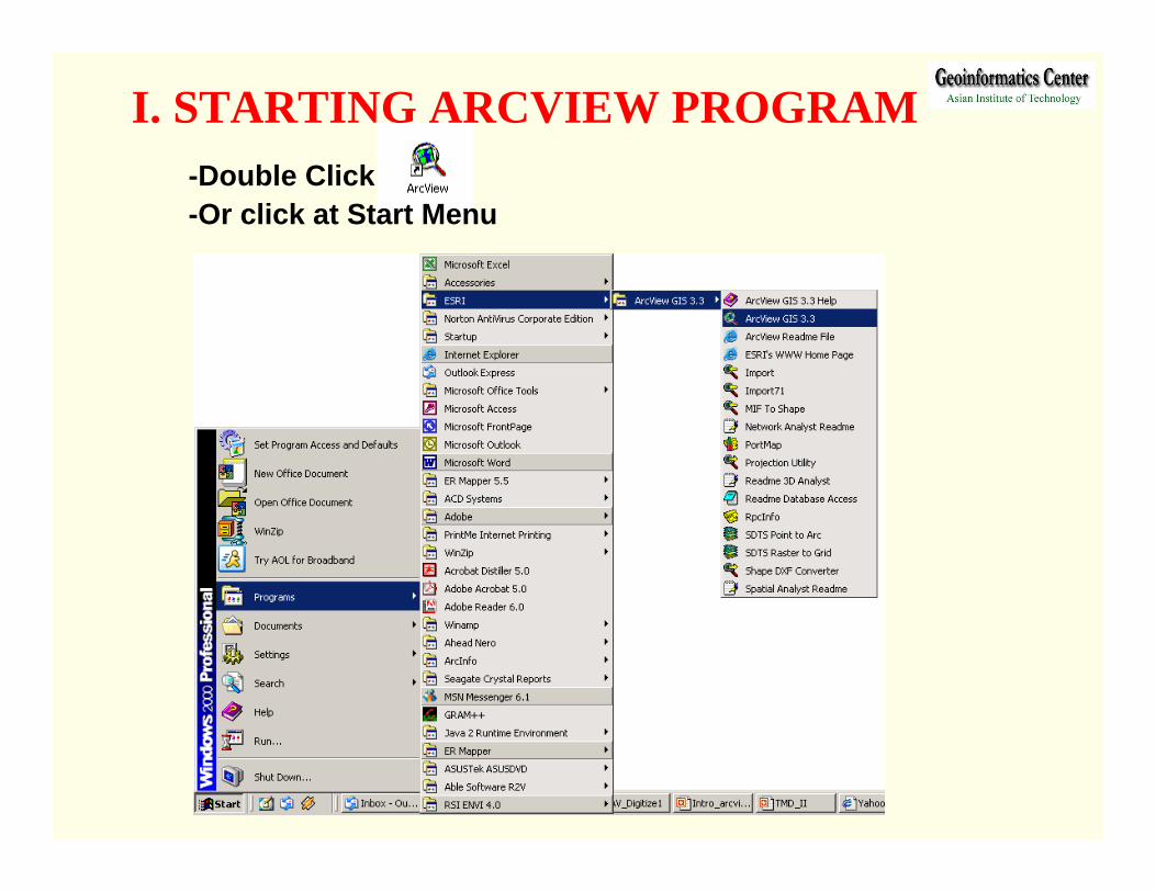
I. STARTING ARCVIEW PROGRAM-Double Click -Or click at Start Menu
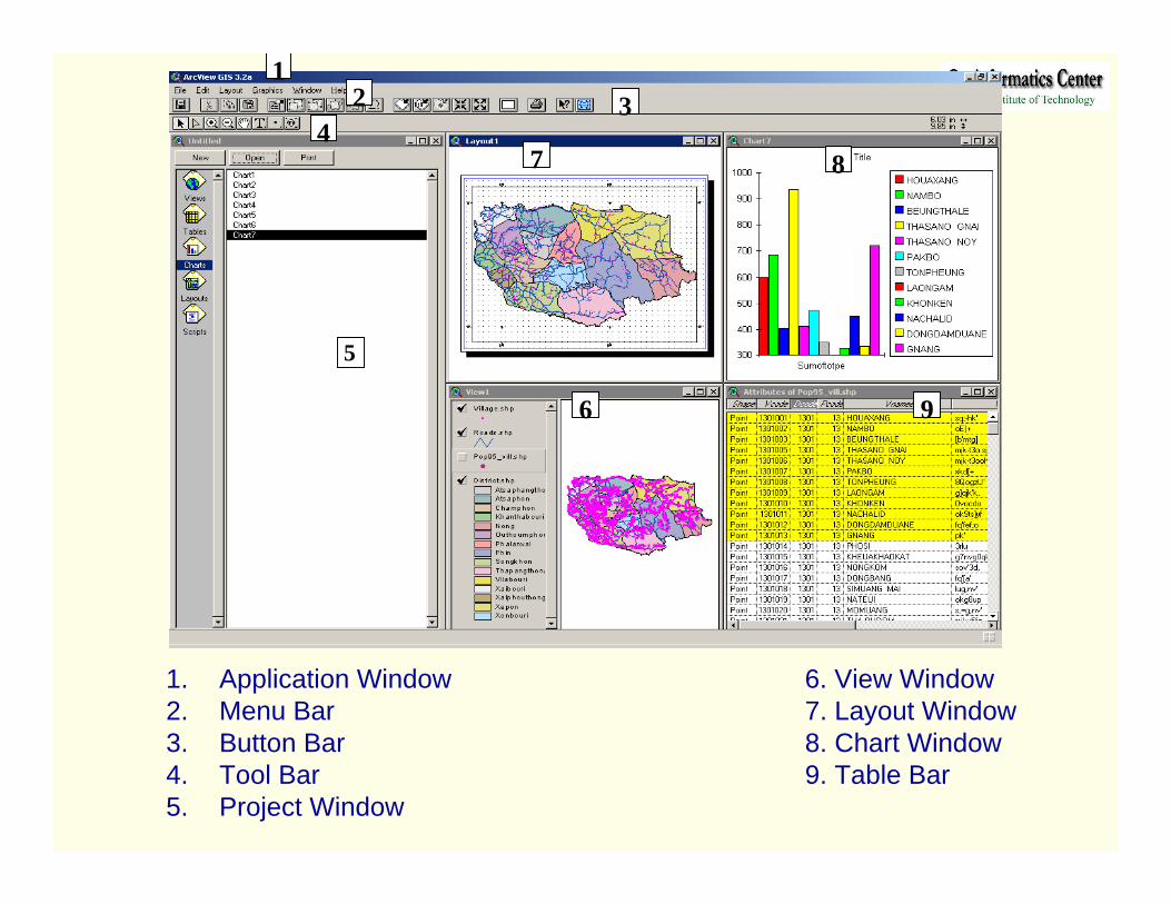
1. Application Window 6. View Window2. Menu Bar 7. Layout Window3. Button Bar 8. Chart Window4. Tool Bar 9. Table Bar5. Project Window
1
5
2 3
84
6 9
7
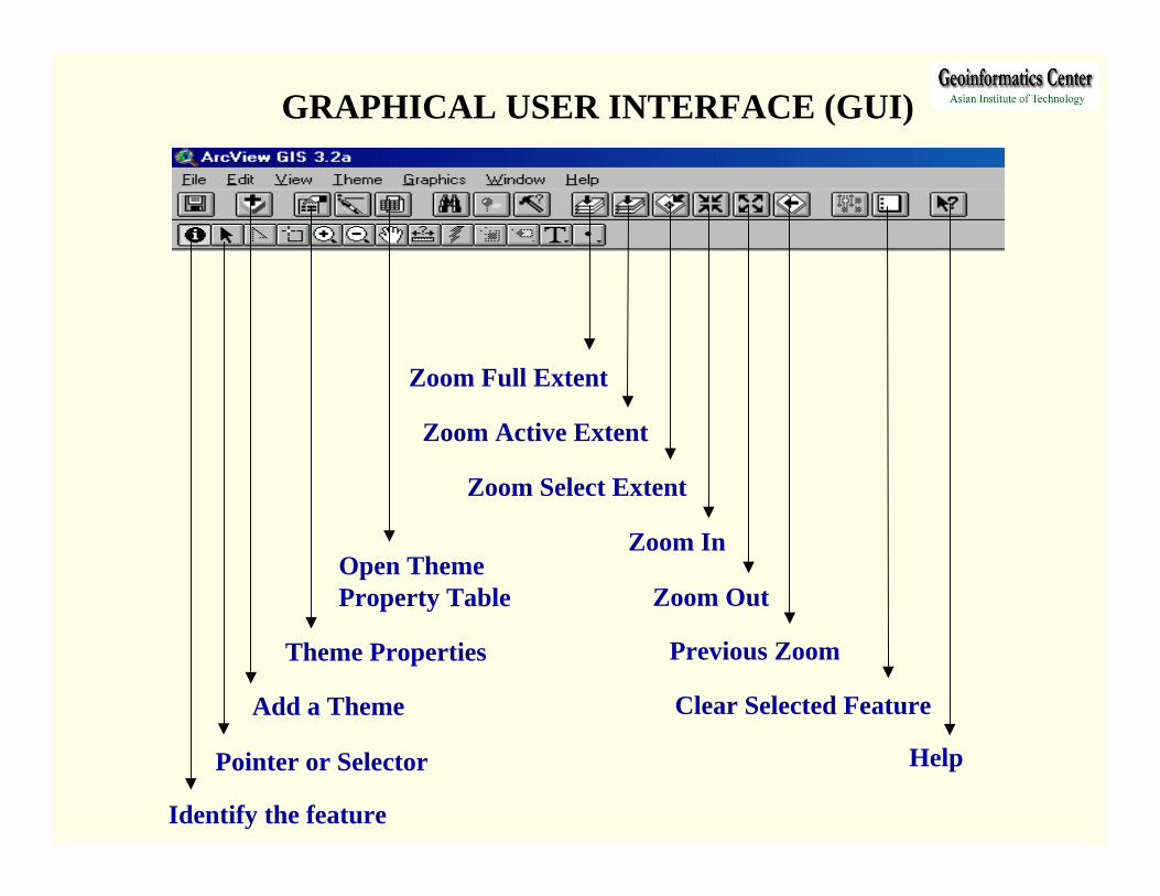
Identify the feature
Pointer or Selector
Add a Theme
Theme Properties
Open Theme Property Table
Zoom Full Extent
Zoom Active Extent
Zoom Select Extent
Zoom In
Zoom Out
Previous Zoom
Clear Selected Feature
Help
GRAPHICAL USER INTERFACE (GUI)
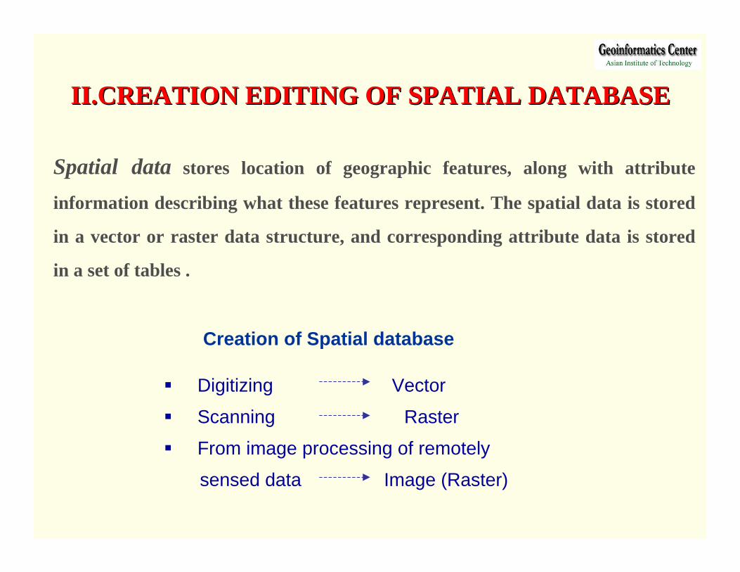
Digitizing Vector
Scanning Raster
From image processing of remotely
sensed data Image (Raster)
Spatial data stores location of geographic features, along with attribute
information describing what these features represent. The spatial data is stored
in a vector or raster data structure, and corresponding attribute data is stored
in a set of tables .
II.CREATION EDITING OF SPATIAL DATABASEII.CREATION EDITING OF SPATIAL DATABASE
Creation of Spatial database
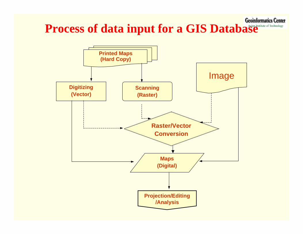
Printed Maps(Hard Copy)
Digitizing (Vector)
Raster/Vector Conversion
Scanning (Raster)
Maps(Digital)
Projection/Editing /Analysis
Image
Process of data input for a GIS Database
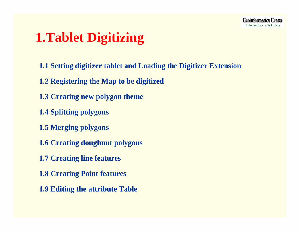
1.1 Setting digitizer tablet and Loading the Digitizer Extension
1.2 Registering the Map to be digitized
1.3 Creating new polygon theme
1.4 Splitting polygons
1.5 Merging polygons
1.6 Creating doughnut polygons
1.7 Creating line features
1.8 Creating Point features
1.9 Editing the attribute Table
1.Tablet Digitizing

Turn on digitizer tablet
Be ensure that the driver of digitizer tablet is installed
Double click on on TabletWork icon at the Desktop Tray near clock.
Once TabletWorks Control Panel window is loaded, assign specific
function to the buttons (Ex: Left click on button 0, Double click left button 1,
Right click on button 2, and Double click right button 3).
Click OK Restart the computer to activate the digitizer
AssignDouble click right
Activate
1.1 Setting digitizer tablet and Loading the Digitizer Extension
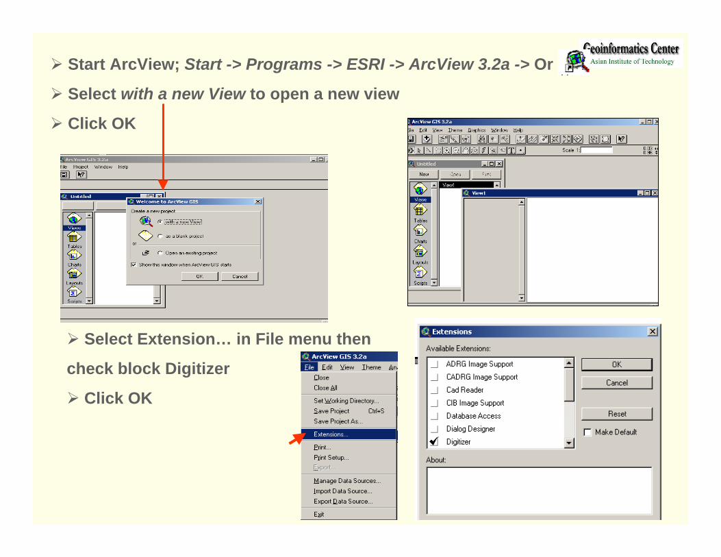
Select Extension… in File menu then
check block Digitizer
Click OK
Start ArcView; Start -> Programs -> ESRI -> ArcView 3.2a -> Or
Select with a new View to open a new view
Click OK
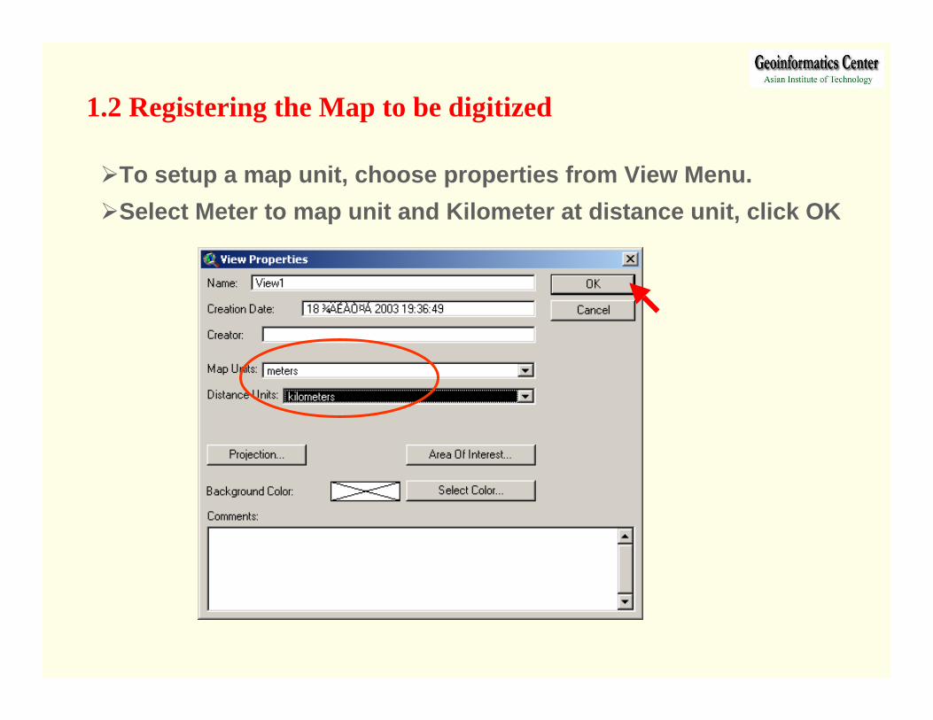
To setup a map unit, choose properties from View Menu.Select Meter to map unit and Kilometer at distance unit, click OK
1.2 Registering the Map to be digitized
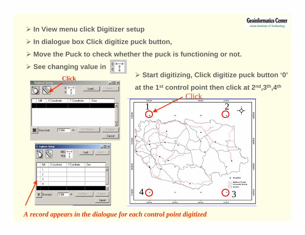
In View menu click Digitizer setup
In dialogue box Click digitize puck button,
Move the Puck to check whether the puck is functioning or not.
See changing value inClick Start digitizing, Click digitize puck button ‘0’
at the 1st control point then click at 2nd,3th,4th
A record appears in the dialogue for each control point digitized
1 2
34
Click

500000
650000
650000
500000
1900000
1900000
1750000
1750000
Write down ground coordinates for all recorded
control points in the X and Y Coordinate fields, then
type to each record
Check The Root Mean Square (RMS) that it should
be lower than the Error Limit.
Click Register button, once it is activatedIf the calculated error is larger than the Error Limit, you cannot register your map, and you’ll have to do one of the following:• Re-digitize control points on your paper map.• Re-enter the corresponding ground control points.• Increase the value in the Error Limit edit box and press TAB key.
The value of the Error Limit field can be increased depending on the scale of map and accuracy level. To maintain highly accurate geographic data, the RMS should be kept under 0.004 inches in page units. For less accurate data, the value can be as high as 0.008 inches or its equivalent measure.
Switching between digitizing mode and mouse modesPress F2 from key board or go to view menu and
select Digitizer as puck or Digitizer as Mouse
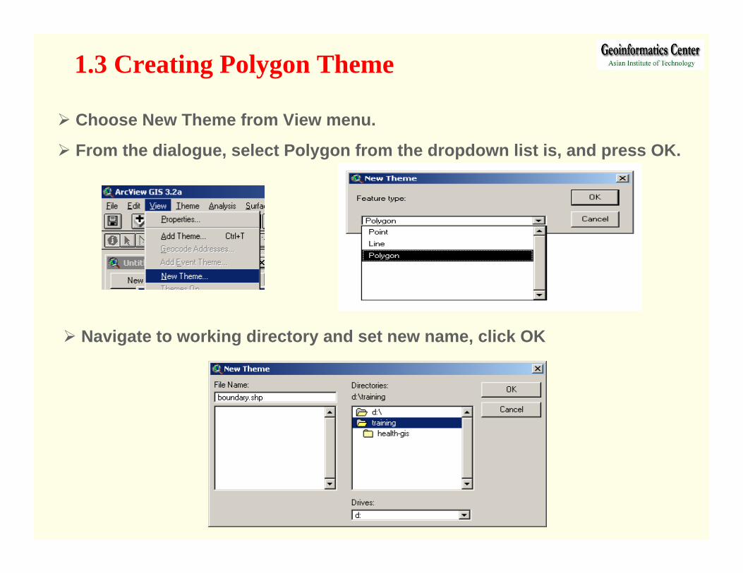
1.3 Creating Polygon Theme
Choose New Theme from View menu.
From the dialogue, select Polygon from the dropdown list is, and press OK.
Navigate to working directory and set new name, click OK
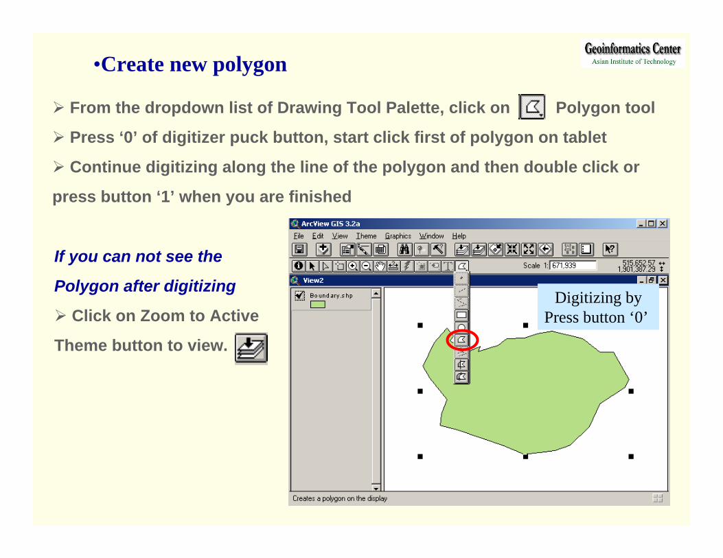
From the dropdown list of Drawing Tool Palette, click on Polygon tool
Press ‘0’ of digitizer puck button, start click first of polygon on tablet
Continue digitizing along the line of the polygon and then double click or
press button ‘1’ when you are finished
Digitizing byPress button ‘0’
If you can not see the
Polygon after digitizing
Click on Zoom to Active
Theme button to view.
•Create new polygon
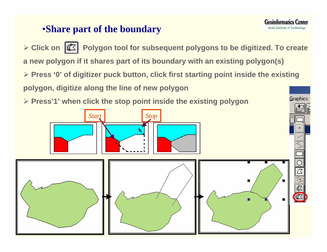
•Share part of the boundary
Click on Polygon tool for subsequent polygons to be digitized. To create
a new polygon if it shares part of its boundary with an existing polygon(s)
Press ‘0’ of digitizer puck button, click first starting point inside the existing
polygon, digitize along the line of new polygon
Press’1’ when click the stop point inside the existing polygon
Start Stop
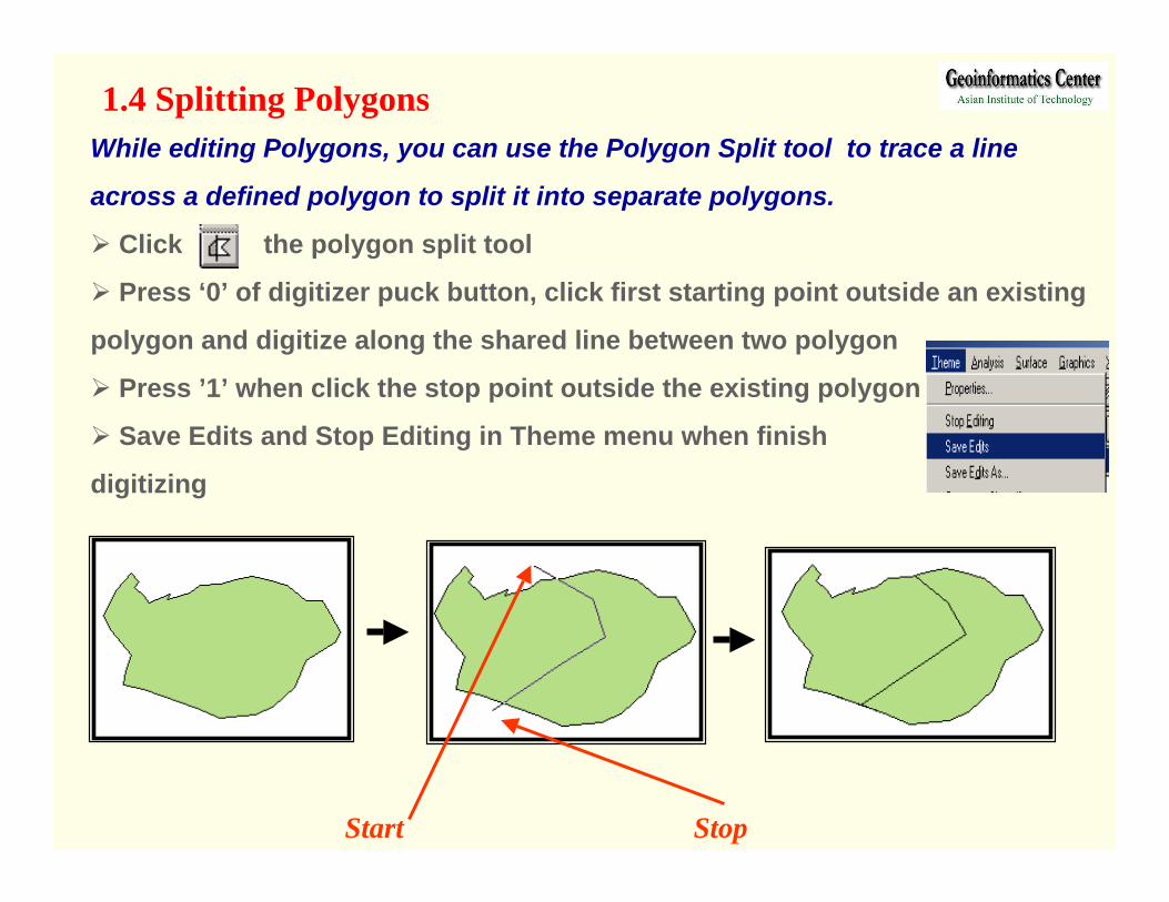
While editing Polygons, you can use the Polygon Split tool to trace a line
across a defined polygon to split it into separate polygons.
Click the polygon split tool
Press ‘0’ of digitizer puck button, click first starting point outside an existing
polygon and digitize along the shared line between two polygon
Press ’1’ when click the stop point outside the existing polygon
Save Edits and Stop Editing in Theme menu when finish
digitizing
1.4 Splitting Polygons
Start Stop
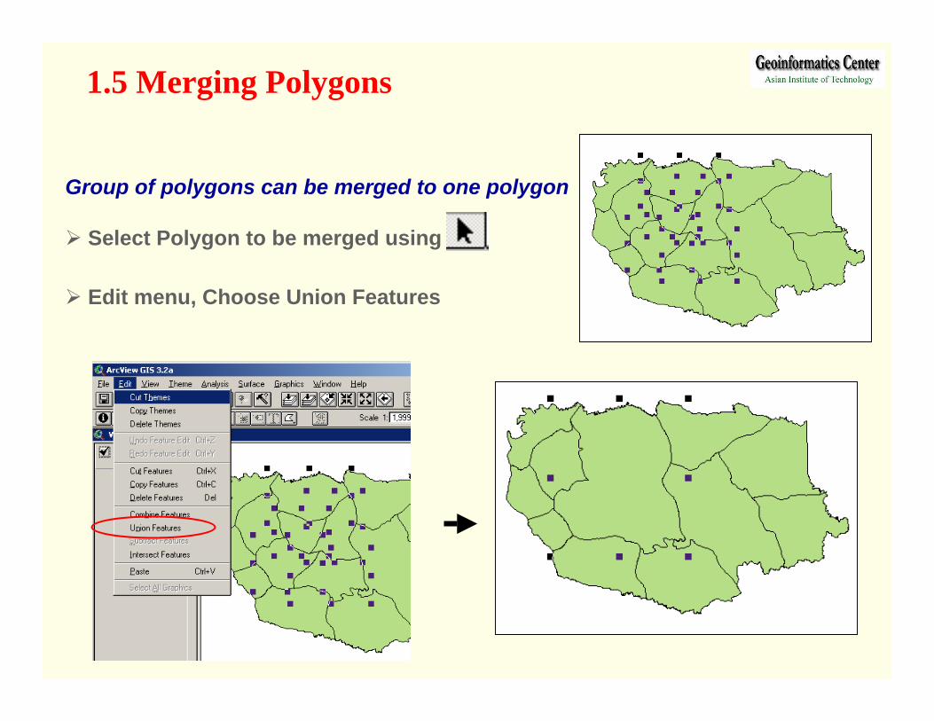
1.5 Merging Polygons
Group of polygons can be merged to one polygon
Select Polygon to be merged using
Edit menu, Choose Union Features
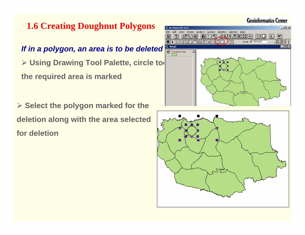
1.6 Creating Doughnut Polygons
If in a polygon, an area is to be deleted
Using Drawing Tool Palette, circle tool,
the required area is marked
Select the polygon marked for the
deletion along with the area selected
for deletion
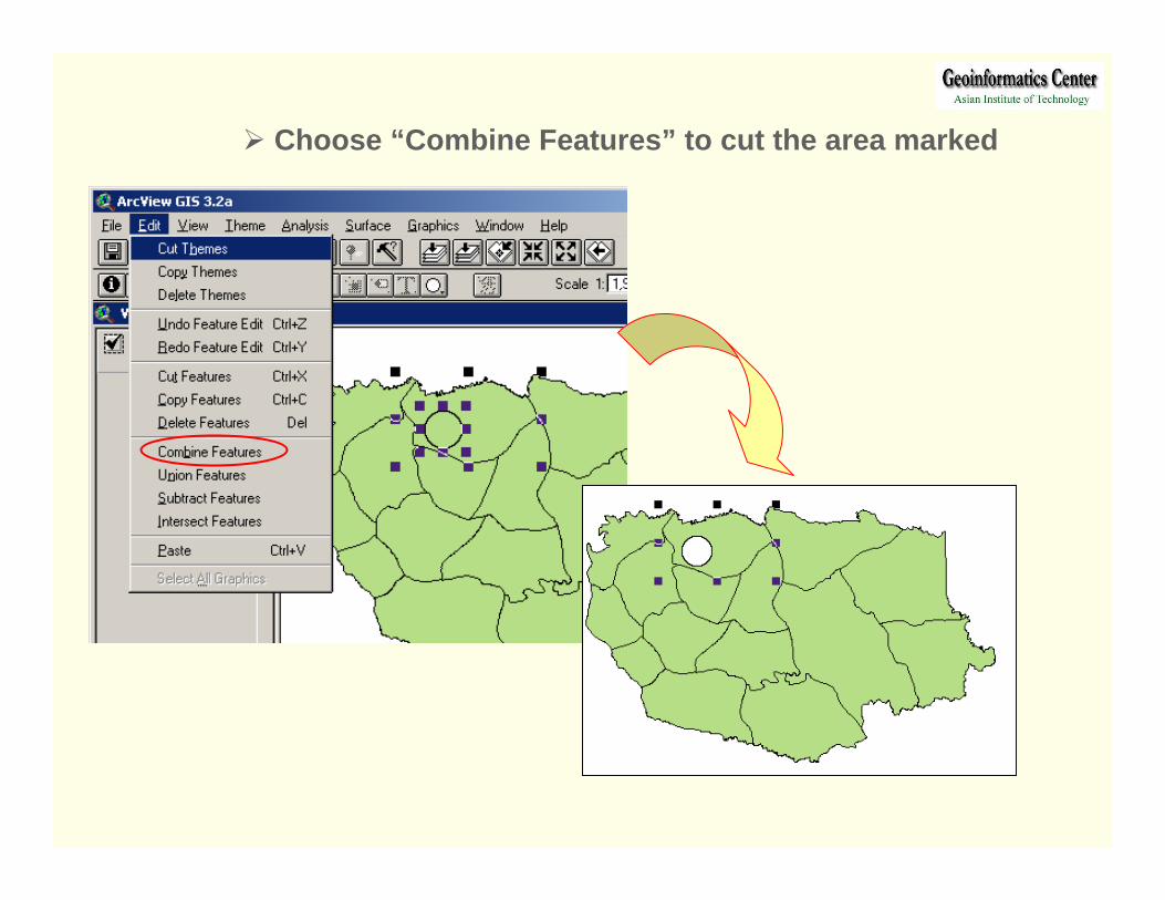
Choose “Combine Features” to cut the area marked
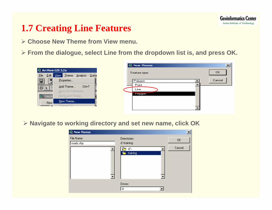
1.7 Creating Line Features
Navigate to working directory and set new name, click OK
Choose New Theme from View menu.
From the dialogue, select Line from the dropdown list is, and press OK.
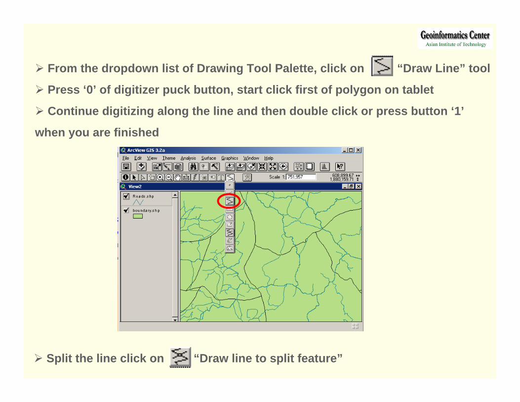
From the dropdown list of Drawing Tool Palette, click on “Draw Line” tool
Press ‘0’ of digitizer puck button, start click first of polygon on tablet
Continue digitizing along the line and then double click or press button ‘1’
when you are finished
Split the line click on “Draw line to split feature”
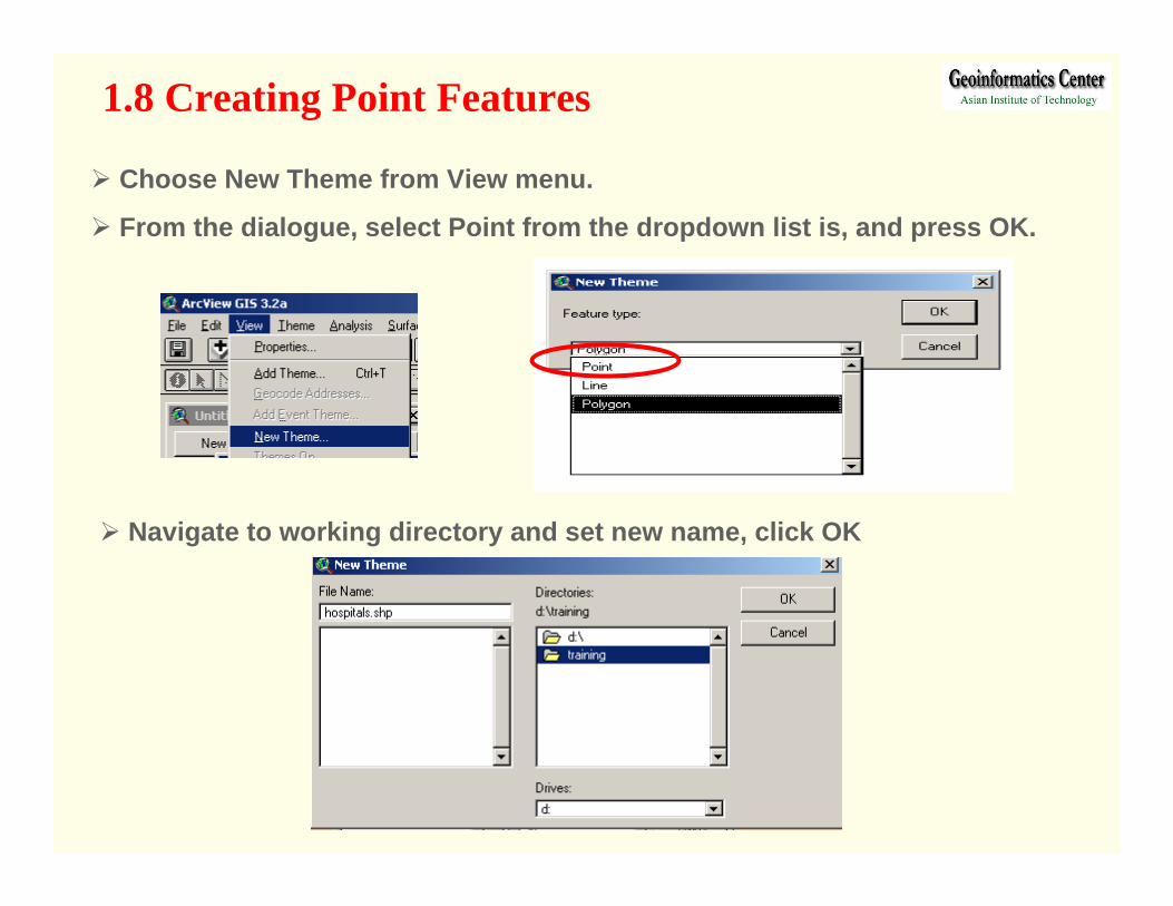
1.8 Creating Point Features
Navigate to working directory and set new name, click OK
Choose New Theme from View menu.
From the dialogue, select Point from the dropdown list is, and press OK.
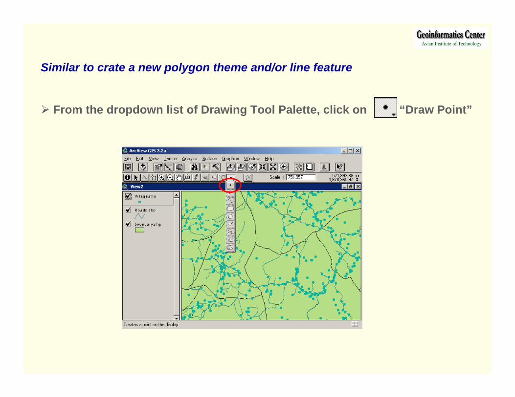
Similar to crate a new polygon theme and/or line feature
From the dropdown list of Drawing Tool Palette, click on “Draw Point”

1.9 Editing the attribute Table
Activate our digitized map of previous steps (Boundary.shp)
Open attribute table of this theme, select Table in Theme menu or click
Activate on the table and click Start Editing in Table menu
Input Id number into ID field
Select Add Field
Add a new field Name: Area
Type: number, Width: 10 and Decimal Places: 2
Click OK

When we digitize our data with ArcInfo, the software calculates the area and
perimeter of the polygons by itself. But in ArcView we have to request to
calculate the area and perimeter.
Click activate on ‘Area’ Field name in the table
Click on calculator and type [Shape].returnarea into the text box
Click OK, Select Save Edit and Stop Editing in Table Menu
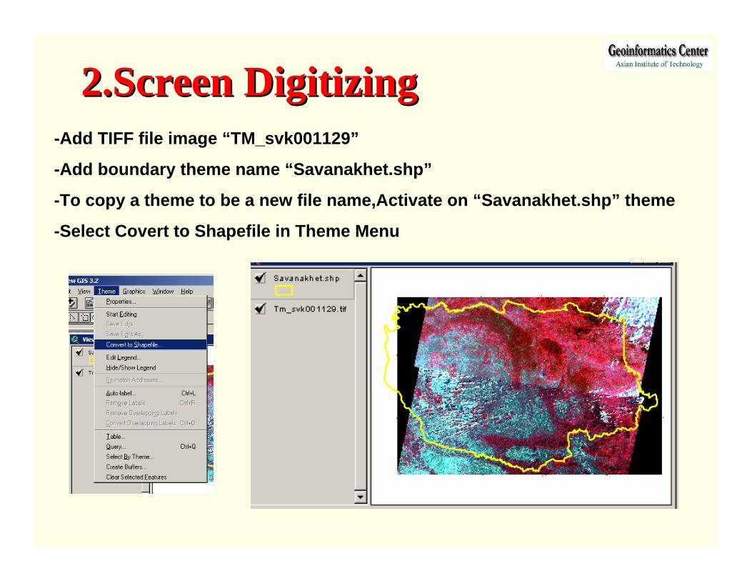
2.Screen Digitizing2.Screen Digitizing-Add TIFF file image “TM_svk001129”
-Add boundary theme name “Savanakhet.shp”
-To copy a theme to be a new file name,Activate on “Savanakhet.shp” theme
-Select Covert to Shapefile in Theme Menu
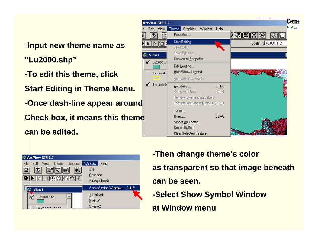
-Input new theme name as
“Lu2000.shp”
-To edit this theme, click
Start Editing in Theme Menu.
-Once dash-line appear around
Check box, it means this theme
can be edited.
-Then change theme’s color as transparent so that image beneath can be seen. -Select Show Symbol Window at Window menu
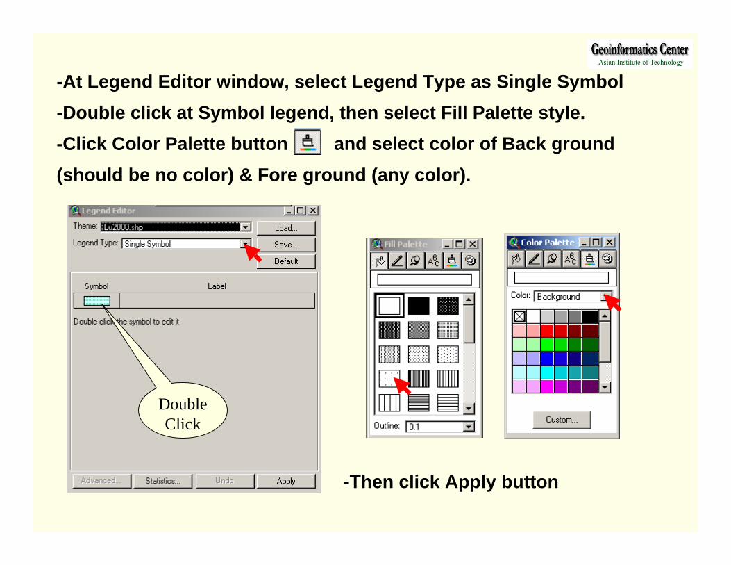
-At Legend Editor window, select Legend Type as Single Symbol-Double click at Symbol legend, then select Fill Palette style.-Click Color Palette button and select color of Back ground (should be no color) & Fore ground (any color).
-Then click Apply button
DoubleClick
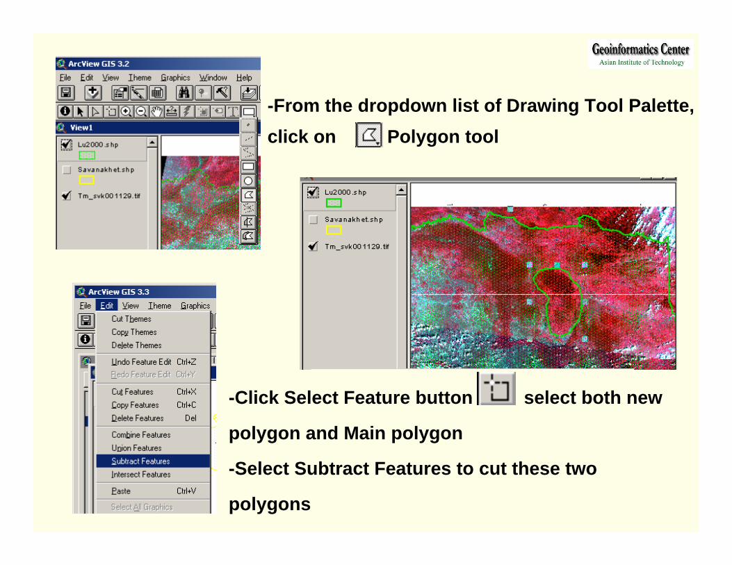
-Click Select Feature button select both new
polygon and Main polygon
-Select Subtract Features to cut these two
polygons
-From the dropdown list of Drawing Tool Palette, click on Polygon tool
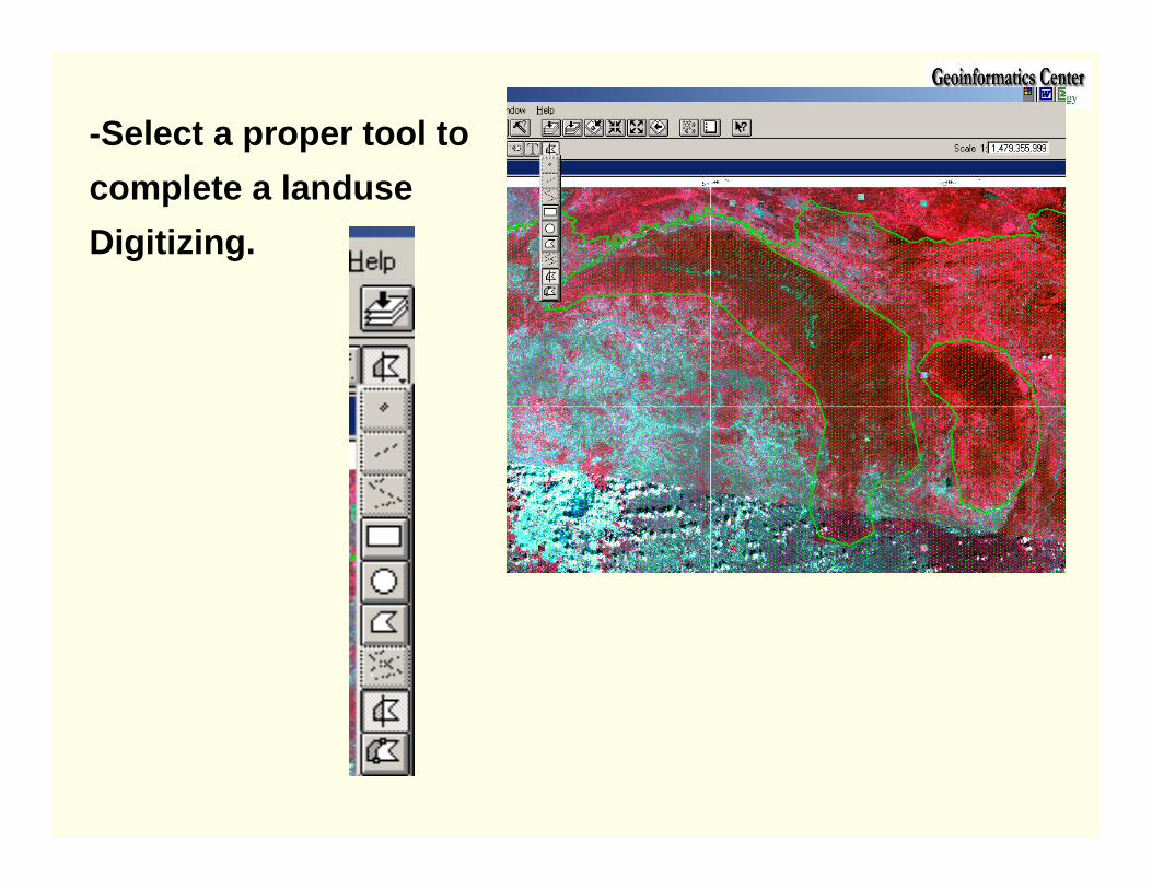
-Select a proper tool tocomplete a landuseDigitizing.
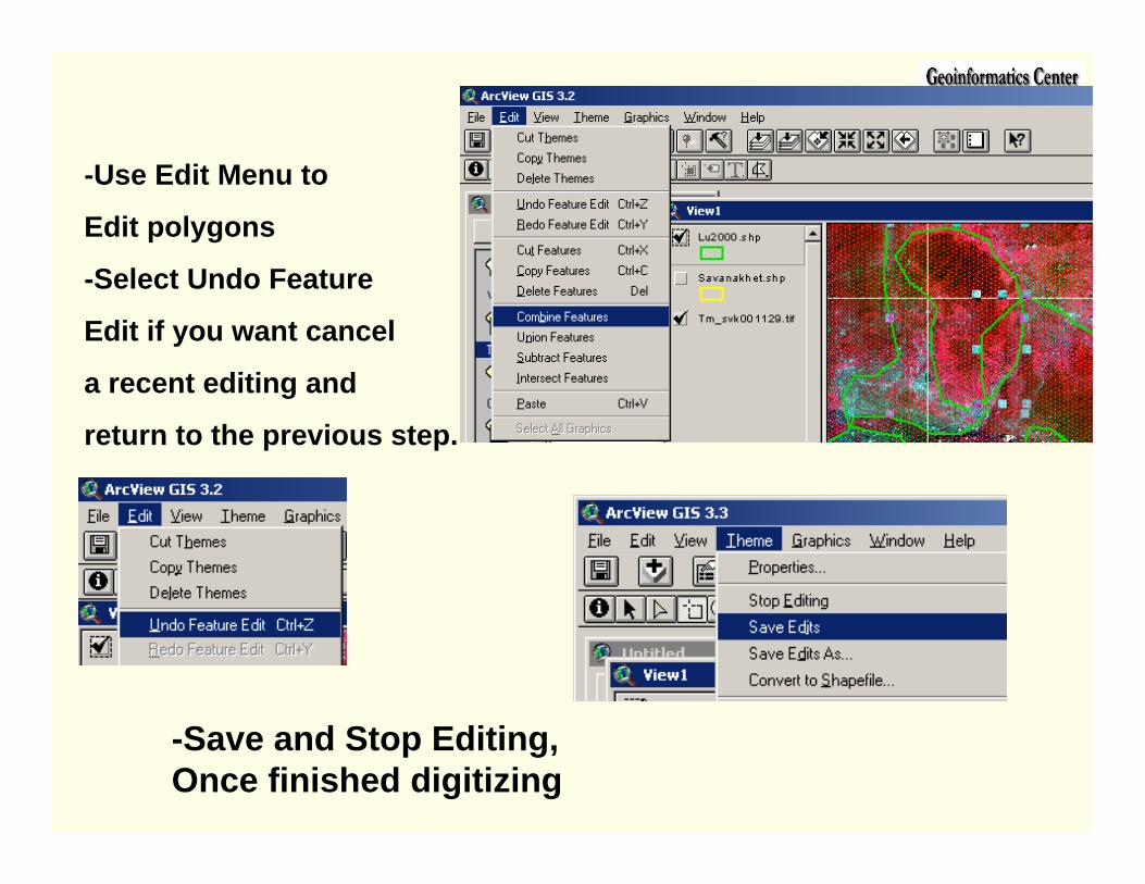
-Use Edit Menu to
Edit polygons
-Select Undo Feature
Edit if you want cancel
a recent editing and
return to the previous step.
-Save and Stop Editing,Once finished digitizing