ghibli 26:1 · pdf filei. 2 21 ghibli 26:1 3 pompe pneumatiche per estrusione spare parts...
TRANSCRIPT
ITALIANO
www.larius.eu
Ghibli 26:1
Ediz. 02 - 09/2017
Pneumatic pump for extrusion
INS
TR
UC
TIO
N M
AN
UA
L
Ediz. 02 - 09/2017www.larius.eu
GHIBLI 26:1
2
Due to a constant product improvement programme, the factory reserves the right to modify technical details mentioned in this manual without prior notice.
This manual is to be considered as an English language translation of the original manual in Italian. The manufacturer shall bear no responsibility for any damages or inconveniences that may arise due to the incorrect translation of the instructions contained within the original manual in Italian.
Ediz. 02 - 09/2017 www.larius.eu
GHIBLI 26:1
3
POMPE PNEUMATICHE PER ESTRUSIONE
spAre pArTs
EXPLODED VIEW OF PNEUMATIC MOTOR .....p.34
EXPLODED VIEW OF PUMPING
STANDARD GROUP. ............................................... p.36
ACCESSORIES ..................................................p.38
INDEX .................................................................P. 3
WARNINGS ........................................................P. 5
WORKING PRINCIPLE .......................................p. 6
TECHNICAL DATA .............................................p. 6
DESCRIPTION OF THE EQUIPMENT ................p. 8
TRANSPORT AND UNPACKING ........................p. 9
SAFETY RULES ..................................................p. 9
CONDITIONS OF GUARANTEE .........................p.10
TYPICAL INSTALLATION ....................................p.10
SETTING-UP ......................................................p.11
WORKING ..........................................................p.11
CLEANING AT THE END OF THE WORK ...........p.12
ROUTINE MAINTENANCE .................................p.12
DISASSEMbLY AND REASSEMbLY
OF THE PUMPING UNIT ....................................p.13
MANUAL RESET OF THE PNEUMATIC
MOTOR ..............................................................p.27
DISASSEMbLY AND REASSEMbLY
OF THE PNEUMATIC MOTOR ...........................p.28
PRObLEMS AND SOLUTIONS ..........................p.31
Q
OPA
bCDE
FGH
JK
L
M
I
N
We ADVIse THe Use OF THIs eQUIpMeNT ONLY BY prOFessIONAL OperATOrs.ONLY Use THIs MACHINe FOr UsAGe speCIFICALLY MeNTIONeD IN THIs MANUAL.
Thank you for choosing a LArIUs s.r.L. product. As well as the productpurchased, you will receive a range of support services
enabling you to achieve the results desired, quickly and professionally.

Ediz. 02 - 09/2017www.larius.eu
GHIBLI 26:1
4
White page
intentionally
Ediz. 02 - 09/2017 www.larius.eu
GHIBLI 26:1
5
0
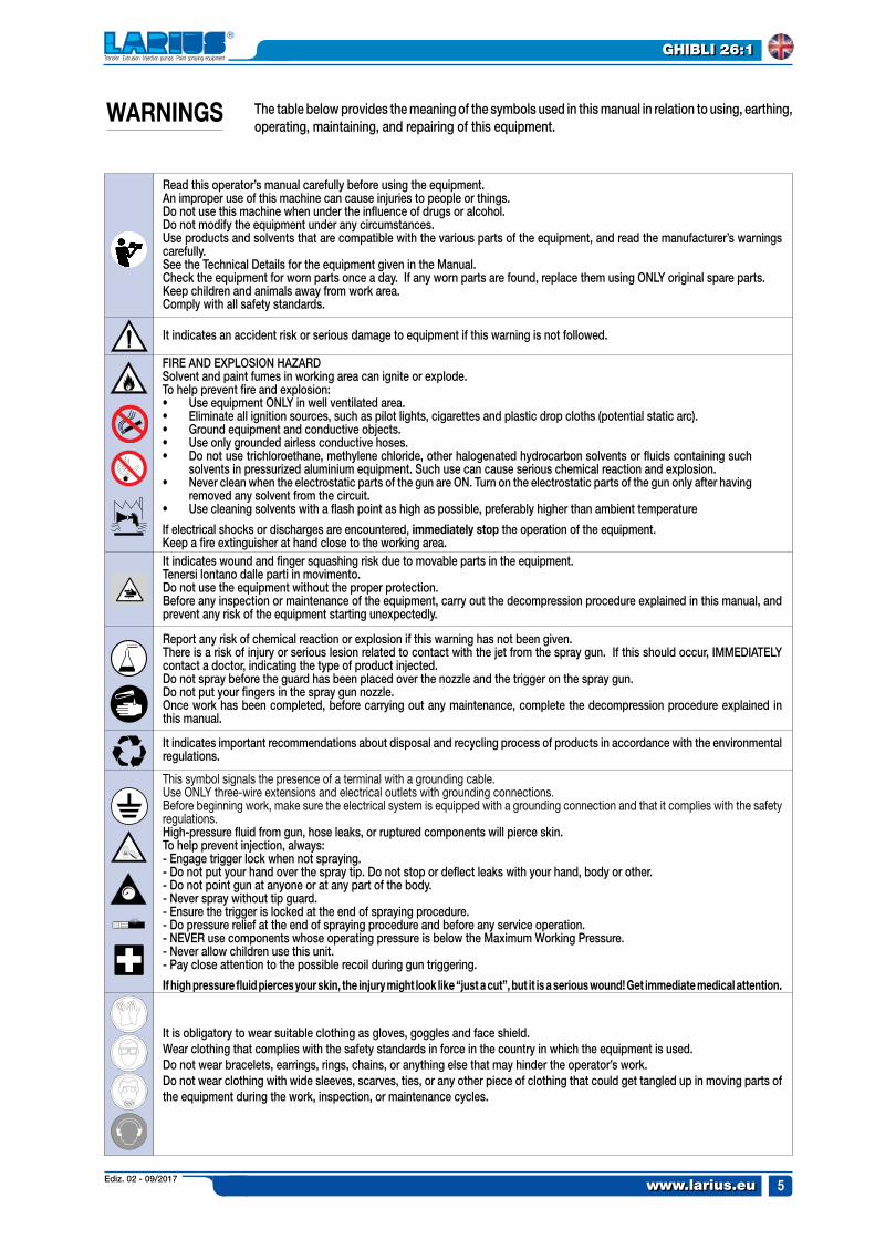
Read this operator’s manual carefully before using the equipment.An improper use of this machine can cause injuries to people or things.Do not use this machine when under the influence of drugs or alcohol.Do not modify the equipment under any circumstances.Use products and solvents that are compatible with the various parts of the equipment, and read the manufacturer’s warnings carefully.See the Technical Details for the equipment given in the Manual.Check the equipment for worn parts once a day. If any worn parts are found, replace them using ONLY original spare parts.Keep children and animals away from work area.Comply with all safety standards.
It indicates an accident risk or serious damage to equipment if this warning is not followed.
It indicates important recommendations about disposal and recycling process of products in accordance with the environmental regulations.
WArNINGs The table below provides the meaning of the symbols used in this manual in relation to using, earthing, operating, maintaining, and repairing of this equipment.
It indicates wound and finger squashing risk due to movable parts in the equipment.Tenersi lontano dalle parti in movimento.Do not use the equipment without the proper protection.Before any inspection or maintenance of the equipment, carry out the decompression procedure explained in this manual, and prevent any risk of the equipment starting unexpectedly.
Report any risk of chemical reaction or explosion if this warning has not been given.There is a risk of injury or serious lesion related to contact with the jet from the spray gun. If this should occur, IMMEDIATELY contact a doctor, indicating the type of product injected.Do not spray before the guard has been placed over the nozzle and the trigger on the spray gun.Do not put your fingers in the spray gun nozzle.Once work has been completed, before carrying out any maintenance, complete the decompression procedure explained in this manual.
This symbol signals the presence of a terminal with a grounding cable.Use ONLY three-wire extensions and electrical outlets with grounding connections.before beginning work, make sure the electrical system is equipped with a grounding connection and that it complies with the safety regulations.High-pressure fluid from gun, hose leaks, or ruptured components will pierce skin.To help prevent injection, always:- Engage trigger lock when not spraying.- Do not put your hand over the spray tip. Do not stop or deflect leaks with your hand, body or other.- Do not point gun at anyone or at any part of the body.- Never spray without tip guard.- Ensure the trigger is locked at the end of spraying procedure.- Do pressure relief at the end of spraying procedure and before any service operation.- NEVER use components whose operating pressure is below the Maximum Working Pressure.- Never allow children use this unit.- Pay close attention to the possible recoil during gun triggering.
If high pressure fluid pierces your skin, the injury might look like “just a cut”, but it is a serious wound! Get immediate medical attention.
It is obligatory to wear suitable clothing as gloves, goggles and face shield.Wear clothing that complies with the safety standards in force in the country in which the equipment is used.Do not wear bracelets, earrings, rings, chains, or anything else that may hinder the operator’s work.Do not wear clothing with wide sleeves, scarves, ties, or any other piece of clothing that could get tangled up in moving parts of the equipment during the work, inspection, or maintenance cycles.
FIRE AND EXPLOSION HAZARDSolvent and paint fumes in working area can ignite or explode.To help prevent fire and explosion:• Use equipment ONLY in well ventilated area.• Eliminate all ignition sources, such as pilot lights, cigarettes and plastic drop cloths (potential static arc).• Ground equipment and conductive objects.• Use only grounded airless conductive hoses.• Do not use trichloroethane, methylene chloride, other halogenated hydrocarbon solvents or fluids containing such
solvents in pressurized aluminium equipment. Such use can cause serious chemical reaction and explosion.• Never clean when the electrostatic parts of the gun are ON. Turn on the electrostatic parts of the gun only after having
removed any solvent from the circuit.• Use cleaning solvents with a flash point as high as possible, preferably higher than ambient temperature
If electrical shocks or discharges are encountered, immediately stop the operation of the equipment. Keep a fire extinguisher at hand close to the working area.
Ediz. 02 - 09/2017www.larius.eu
GHIBLI 26:1
6
3-7 bar
182 bar
1/2" GAS (F)
4 l/m (6,4 cpm)
15
60
3/4" GAS CON. (F)
<80 dB (A)
GHIBLI 26:1
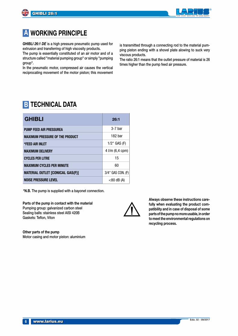
WOrKING prINCIpLeGHIBLI 26:1 DE is a high pressure pneumatic pump used for extrusion and transferring of high viscosity products. The pump is essentially constituted of an air motor and of a structure called "material pumping group" or simply "pumping group".In the pneumatic motor, compressed air causes the vertical reciprocating movement of the motor piston; this movement
is transmitted through a connecting rod to the material pum-ping piston ending with a shovel plate alowing to suck very viscous products.The ratio 26:1 means that the outlet pressure of material is 26 times higher than the pump feed air pressure.
A
TeCHNICAL DATAB
*N.B. The pump is supplied with a bayonet connection.
parts of the pump in contact with the material Pumping group: galvanized carbon steelSealing balls: stainless steel AISI 420BGaskets: Teflon, Viton
Other parts of the pumpMotor casing and motor piston: aluminium
Always observe these instructions care-fully when evaluating the product com-patibility and in case of disposal of some parts of the pump no more usable, in order to meet the environmental regulations on recycling process.
PUMP FEED AIR PRESSUREA
MAXIMUM PRESSURE OF THE PRODUCT
*FEED AIR INLET
MAXIMUM DELIVERY
CYCLES PER LITRE
MAXIMUM CYCLES PER MINUTE
MATERIAL OUTLET [CONICAL GAS(F)]
NOISE PRESSURE LEVEL
Ediz. 02 - 09/2017 www.larius.eu
GHIBLI 26:1
7
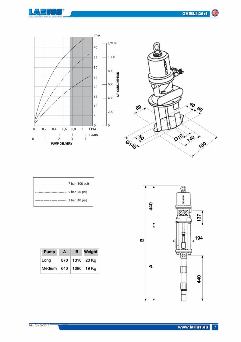
pUMp DeLIVerY
AIr
CONs
UMpT
ION
B 194
A
Ø140
50
69
180140Ø10
40 80
440
137
440
pump
Long
Medium
870
640
A
1310
1080
B
20 Kg
19 Kg
Weight
Ediz. 02 - 09/2017www.larius.eu
GHIBLI 26:1
8
C
pOs.
1
2
3
4
5
Description pOs. Description
6
7
8
9
1
8
5
7
6
2
9
3
4
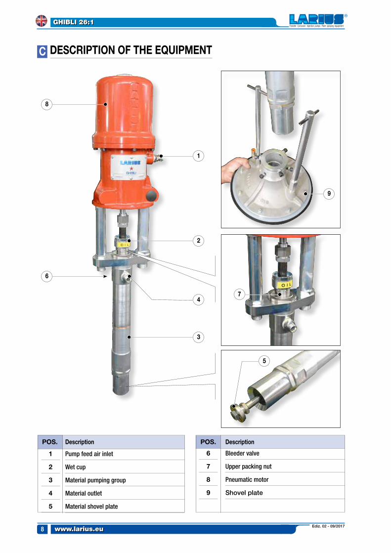
DesCrIpTION OF THe eQUIpMeNT
Pump feed air inlet
Wet cup
Material pumping group
Material outlet
Material shovel plate
Bleeder valve
Upper packing nut
Pneumatic motor
Shovel plate
Ediz. 02 - 09/2017 www.larius.eu
GHIBLI 26:1
9
D
e
TrANspOrT AND UNpACKING
• Thepackedpartsshouldbehandledasindicatedinthesymbols and markings on the outside of the packing.
• Beforeinstallingtheequipment,ensurethattheareatobe used is large enough for such purposes, is properly lit and has a clean, smooth floor surface.
• Theuserisresponsiblefortheoperationsofunloadingand handling and should use the maximum care so as not to damage the individual parts or injure anyone.
To perform the unloading operation, use only qualified and trained personnel (truck and crane operators, etc.) and also suitable hoisting equipment for the weight of the installation or its parts.
Follow carefully all the safety rules. The personnel must be equipped with the necessary
safety clothing.• The manufacturer will not be responsible for the un-
loading operations and transport to the workplace of the machine.
• Check the packing is undamagedon receipt of theequipment. Unpack the machine and verify if there has been any damage due to transportation.
In case of damage, call immediately LArIUs and the Shipping Agent. All the notices about possible damage or anomalies must arrive timely within 8 days at least from the date of receipt of the plant through Registered Letter to the Shipping Agent and to LArIUs.
• Thedisposalofpackagingmaterialsisacustomer’scompetence and must be performed in accordance with the regulations in force in the country where the plant is installed and used.It is nevertheless sound practice to recycle packaging materials in an environment-friendly manner as much as possible.
sAFeTY rULes
• THE EMPLOYER SHALL TRAIN ITS EMPLOYEES ABOUT ALL THOSE RISKS STEMMING FROM ACCI-DENTS, ABOUT THE USE OF SAFETY DEVICES FOR THEIR OWN SAFETY AND ABOUT THE GENERAL RULES FOR ACCIDENT PREVENTION IN COMPLIAN-CE WITH INTERNATIONAL REGULATIONS AND WITH THE LAWS OF THE COUNTRY WHERE THE PLANT IS USED.
• THE BEHAVIOUR OF THE EMPLOYEES SHALL STRICTLY COMPLY WITH THE ACCIDENT PREVENTION AND ALSO ENVIRONMENTAL REGULATIONS IN FORCE IN THE COUNTRY WHERE THE PLANT IS INSTALLED AND USED.
read carefully and entirely the following instructions before using the product. please save these instructions in a safe place.
The unauthorised tampering/replacement of one or more parts composing the machine, the use of accessories, tools, expendable materials other than those recommended by
the Manufacturer can be a danger of accident. The Manufacturer will be relieved from tort and criminal liability.
• KEEP YOUR WORK PLACE CLEAN AND TIDY. DISORDER WHERE YOU ARE WORKING CREATES A POTENTIAL RISK OF ACCIDENTS.
• ALWAYS KEEP PROPER BALANCE AVOIDING UNUSUAL STANCE.
• BEFORE USING THE TOOL, ENSURE THERE ARE NOT DAMAGED PARTS AND THE MACHINE CAN WORK PRO-PERLY.
• ALWAYS FOLLOW THE INSTRUCTIONS ABOUT SAFETY AND THE REGULATIONS IN FORCE.
• KEEP THOSE WHO ARE NOT RESPONSIBLE FOR THE EqUIPMENT OUT OF THE WORK AREA.
• NeVer EXCEED THE MAXIMUM WORKING PRESSURE INDICATED.
• NeVer POINT THE SPRAY GUN AT YOURSELVES OR AT OTHER PEOPLE. THE CONTACT WITH THE CASTING CAN CAUSE SERIOUS INJURIES.
• IN CASE OF INJURIES CAUSED BY THE GUN CASTING, SEEK IMMEDIATE MEDICAL ADVICE SPECIFYING THE TYPE OF THE PRODUCT INJECTED. NeVer UNDERVALUE A WOUND CAUSED BY THE INJECTION OF A FLUID.
• ALWAYS DISCONNECT THE SUPPLY AND RELEASE THE PRESSURE IN THE CIRCUIT BEFORE PERFOR-MING ANY CHECK OR PART REPLACEMENT OF THE EqUIPMENT.
• NEVER MODIFY ANY PART IN THE EqUIPMENT. CHECK REGULARLY THE COMPONENTS OF THE SYSTEM.
REPLACE THE PARTS DAMAGED OR WORN.• TIGHTEN AND CHECK ALL THE FITTINGS FOR
CONNECTION BETWEEN PUMP, FLEXIBLE HOSE AND SPRAY GUN BEFORE USING THE EqUIPMENT.
• ALWAYS USE THE FLEXIBLE HOSE SUPPLIED WITH STANDARD KIT. THE USE OF ANY ACCESSORIES OR TOOLING OTHER THAN THOSE RECOMMENDED IN THIS MANUAL, MAY CAUSE DAMAGE OR INJURE THE OPERATOR.
• THE FLUID CONTAINED IN THE FLEXIBLE HOSE CAN BE VERY DANGEROUS. HANDLE THE FLEXIBLE HOSE CAREFULLY. DO NOT PULL THE FLEXIBLE HOSE TO MOVE THE EqUIPMENT. NEVER USE A DAMAGED OR A REPAIRED FLEXIBLE HOSE.
• NEVER SPRAY OVER FLAMMABLE PRODUCTS OR SOL-VENTS IN CLOSED PLACES.
• NEVER USE THE TOOLING IN PRESENCE OF POTEN-TIALLY EXPLOSIVE GAS.
Ediz. 02 - 09/2017www.larius.eu
GHIBLI 26:1
10
3
2
1
3
2
1
F
1
2,
3
4
5
6
pos.
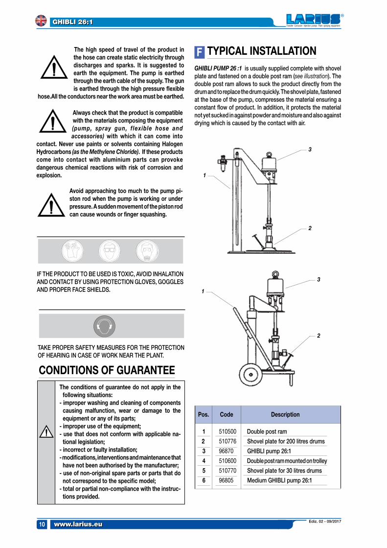
Double post ram
Shovel plate for 200 litres drums
GHIBLI pump 26:1
Double post ram mounted on trolley
Shovel plate for 30 litres drums
Medium GHIBLI pump 26:1
Code Description
510500
510776
96870
510600
510770
96805
Always check that the product is compatible with the materials composing the equipment (pump, spray gun, f lexible hose and accessories) with which it can come into
contact. Never use paints or solvents containing Halogen Hydrocarbons (as the Methylene Chloride). If these products come into contact with aluminium parts can provoke dangerous chemical reactions with risk of corrosion and explosion.
Avoid approaching too much to the pump pi-ston rod when the pump is working or under pressure. A sudden movement of the piston rod can cause wounds or finger squashing.
The high speed of travel of the product in the hose can create static electricity through discharges and sparks. It is suggested to earth the equipment. The pump is earthed through the earth cable of the supply. The gun is earthed through the high pressure flexible
hose.All the conductors near the work area must be earthed.
TYpICAL INsTALLATIONGHIBLI PUMP 26 :1 is usually supplied complete with shovel plate and fastened on a double post ram (see illustration). The double post ram allows to suck the product directly from the drum and to replace the drum quickly. The shovel plate, fastened at the base of the pump, compresses the material ensuring a constant flow of product. In addition, it protects the material not yet sucked in against powder and moisture and also against drying which is caused by the contact with air.
The conditions of guarantee do not apply in the following situations:
- improper washing and cleaning of components causing malfunction, wear or damage to the equipment or any of its parts;
- improper use of the equipment;- use that does not conform with applicable na-
tional legislation;- incorrect or faulty installation;- modifications, interventions and maintenance that
have not been authorised by the manufacturer;- use of non-original spare parts or parts that do
not correspond to the specific model;- total or partial non-compliance with the instruc-
tions provided.
CONDITIONs OF GUArANTee
TAKE PROPER SAFETY MEASURES FOR THE PROTECTION OF HEARING IN CASE OF WORK NEAR THE PLANT.
IF THE PRODUCT TO BE USED IS TOXIC, AVOID INHALATION AND CONTACT BY USING PROTECTION GLOVES, GOGGLES AND PROPER FACE SHIELDS.
Ediz. 02 - 09/2017 www.larius.eu
GHIBLI 26:1
11
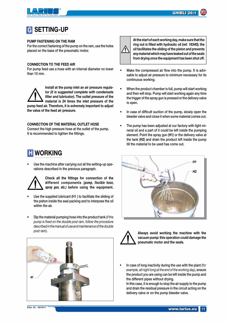
H2
H1
G
H
At the start of each working day, make sure that the ring nut is filled with hydraulic oil (ref. 16340); the oil facilitates the sliding of the piston and prevents any material which may have leaked out of the seals from drying once the equipment has been shut off.
H1
pUMp FAsTeNING ON THe rAMFor the correct fastening of the pump on the ram, use the holes placed on the base of the pneumatic motor.
CONNeCTION TO THe FeeD AIrFor pump feed use a hose with an internal diameter no lower than 10 mm.
Install at the pump inlet an air pressure regula-tor (it is suggested complete with condensate filter and lubricator). The outlet pressure of the material is 24 times the inlet pressure of the
pump feed air. Therefore, it is extremely important to adjust the value of the feed air pressure.
CONNeCTION OF THe MATerIAL OUTLeT HOseConnect the high pressure hose at the outlet of the pump.It is recommended to tighten the fittings.
WOrKING• Use the machine after carrying out all the setting-up ope-
rations described in the previous paragraph.
Check all the fittings for connection of the different components (pump, flexible hose, spray gun, etc.) before using the equipment.
• Use the supplied lubricant (H1 ) to facilitate the sliding of the piston inside the seal packing and to interpose the oil within the air.
• Dip the material pumping hose into the product tank (if the pump is fixed on the double post ram, follow the procedure described in the manual of use and maintenance of the double post ram). Always avoid working the machine with the
vacuum pump: this operation could damage the pneumatic motor and the seals.
• In case of long inactivity during the use with the plant (for example, all night long at the end of the working day), ensure the product you are using can be left inside the pump and the different pipes without drying.
In this case, it is enough to stop the air supply to the pump and drain the residual pressure in the circuit acting on the delivery valve or on the pump bleeder valve.
• Make the compressed air flow into the pump. It is advi-sable to adjust air pressure to minimum necessary for its continuous working.
• When the product chamber is full, pump will start working and then will stop. Pump will start working again any time the trigger of the spray gun is pressed or the delivery valve is open.
• In case of difficult suction of the pump, slowly open the bleeder valve and close it when some material comes out.
• The pump has been adjusted at our factory with light mi-neral oil and a part of it could be left inside the pumping element. Point the spray gun (H1) or the delivery valve at the tank (H2) and drain the product left inside the pump till the material to be used has come out.
seTTING-Up
Ediz. 02 - 09/2017www.larius.eu
GHIBLI 26:1
12
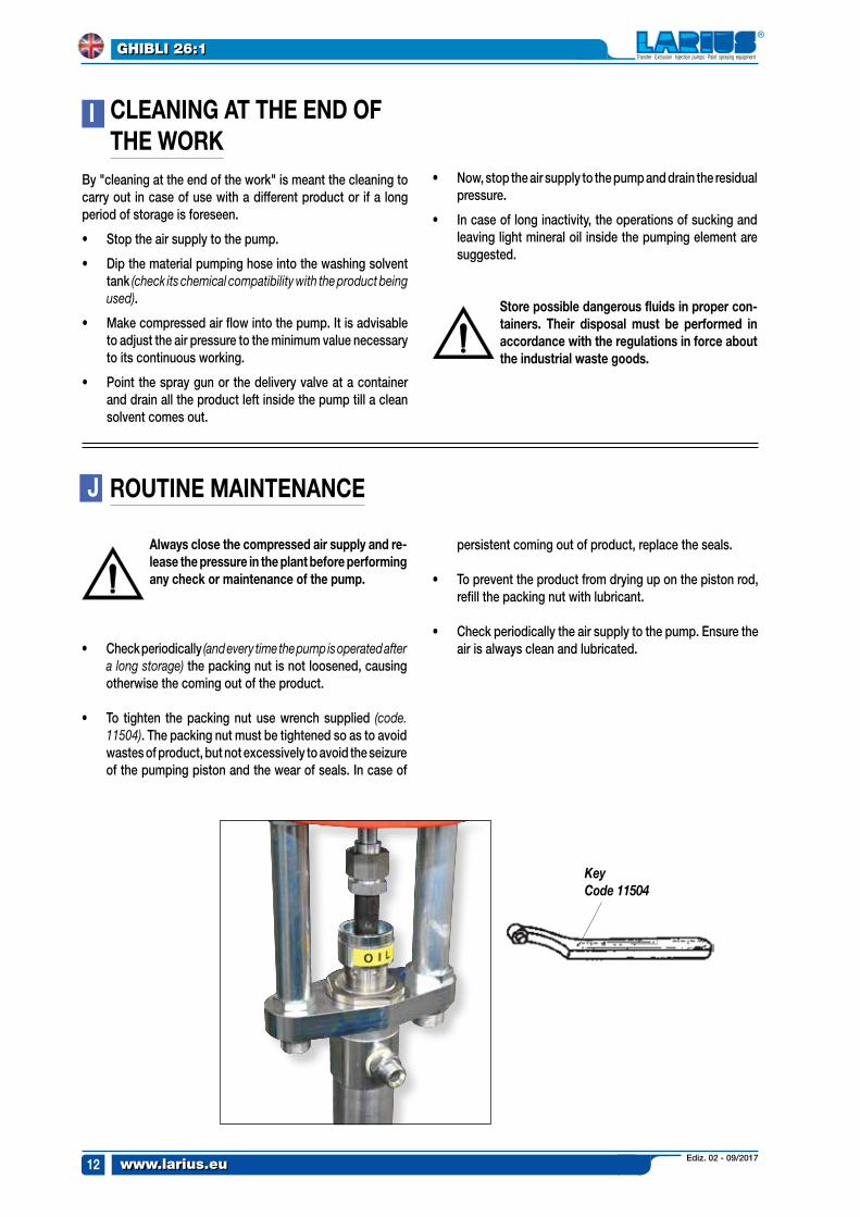
KeyCode 11504
I
J
CLeANING AT THe eND OF THe WOrK
By "cleaning at the end of the work" is meant the cleaning to carry out in case of use with a different product or if a long period of storage is foreseen.
• Stop the air supply to the pump.
• Dip the material pumping hose into the washing solvent tank (check its chemical compatibility with the product being used).
• Make compressed air flow into the pump. It is advisable to adjust the air pressure to the minimum value necessary to its continuous working.
• Point the spray gun or the delivery valve at a container and drain all the product left inside the pump till a clean solvent comes out.
• Now, stop the air supply to the pump and drain the residual pressure.
• In case of long inactivity, the operations of sucking and leaving light mineral oil inside the pumping element are suggested.
store possible dangerous fluids in proper con-tainers. Their disposal must be performed in accordance with the regulations in force about the industrial waste goods.
rOUTINe MAINTeNANCe
Always close the compressed air supply and re-lease the pressure in the plant before performing any check or maintenance of the pump.
• Check periodically (and every time the pump is operated after a long storage) the packing nut is not loosened, causing otherwise the coming out of the product.
• To tighten the packing nut use wrench supplied (code. 11504). The packing nut must be tightened so as to avoid wastes of product, but not excessively to avoid the seizure of the pumping piston and the wear of seals. In case of
persistent coming out of product, replace the seals.
• To prevent the product from drying up on the piston rod, refill the packing nut with lubricant.
• Check periodically the air supply to the pump. Ensure the air is always clean and lubricated.
Ediz. 02 - 09/2017 www.larius.eu
GHIBLI 26:1
13
2
2a 2b
K
1
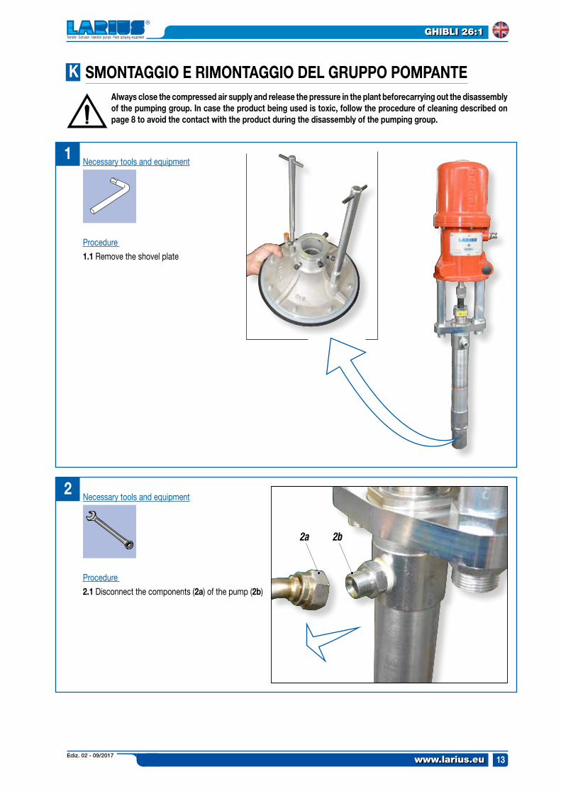
Procedure
1.1 Remove the shovel plate
Procedure
2.1 Disconnect the components (2a) of the pump (2b)
Necessary tools and equipment
Always close the compressed air supply and release the pressure in the plant beforecarrying out the disassembly of the pumping group. In case the product being used is toxic, follow the procedure of cleaning described on page 8 to avoid the contact with the product during the disassembly of the pumping group.
sMONTAGGIO e rIMONTAGGIO DeL GrUppO pOMpANTe
Necessary tools and equipment
Ediz. 02 - 09/2017www.larius.eu
GHIBLI 26:1
14
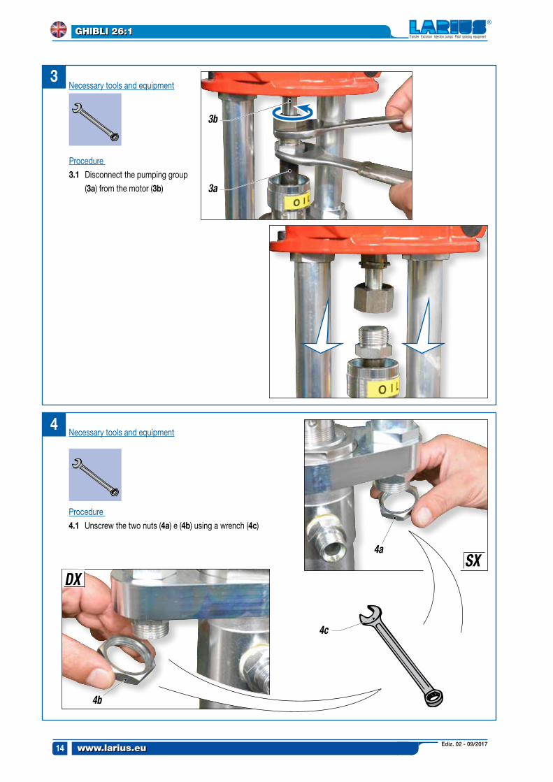
Necessary tools and equipment
Procedure
4.1 Unscrew the two nuts (4a) e (4b) using a wrench (4c)
4
3
3b
3a
4c
4a
4b
SXDX
Procedure
3.1 Disconnect the pumping group
(3a) from the motor (3b)
Necessary tools and equipment
Ediz. 02 - 09/2017 www.larius.eu
GHIBLI 26:1
15
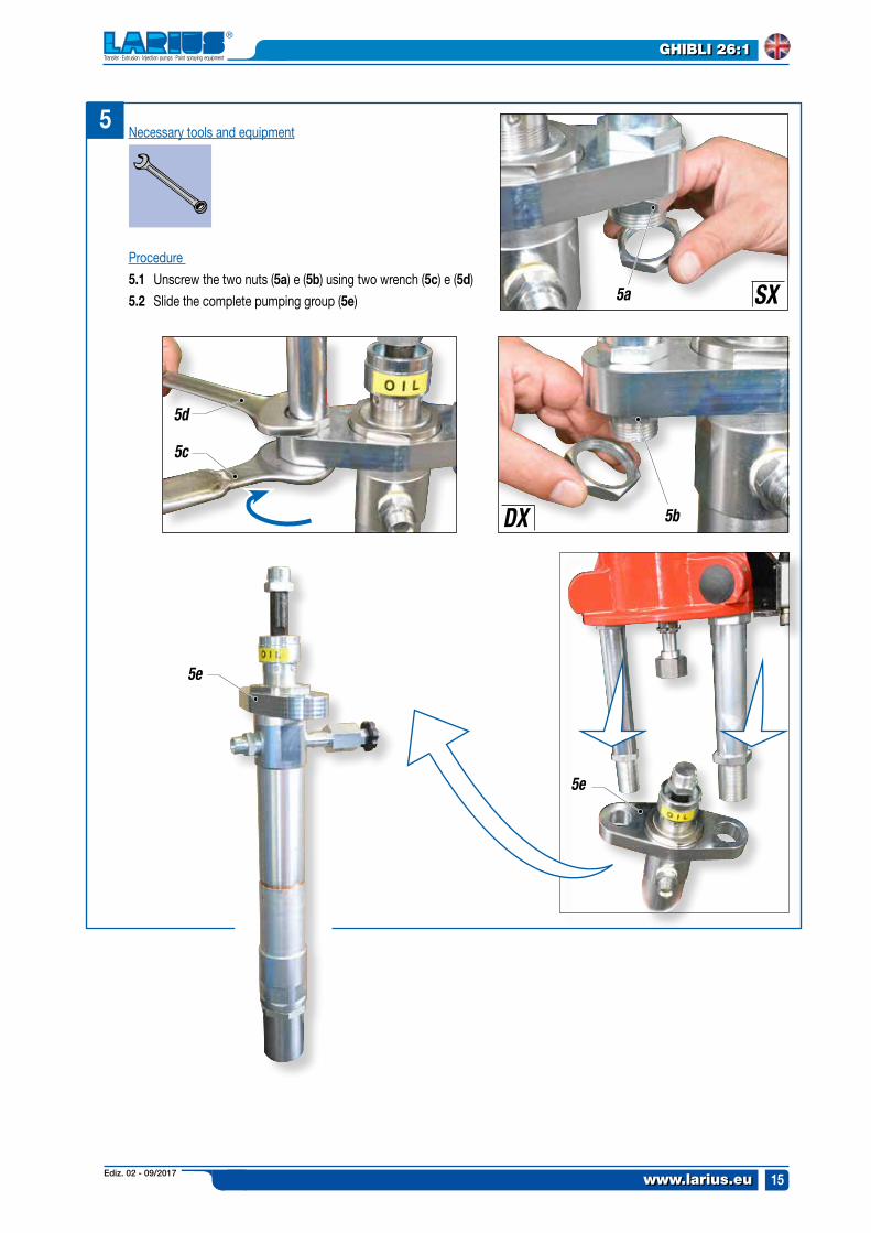
5Necessary tools and equipment
5a
5b
5c
5d
5e
5e
SX
DX
Procedure
5.1 Unscrew the two nuts (5a) e (5b) using two wrench (5c) e (5d)
5.2 Slide the complete pumping group (5e)
Ediz. 02 - 09/2017www.larius.eu
GHIBLI 26:1
16
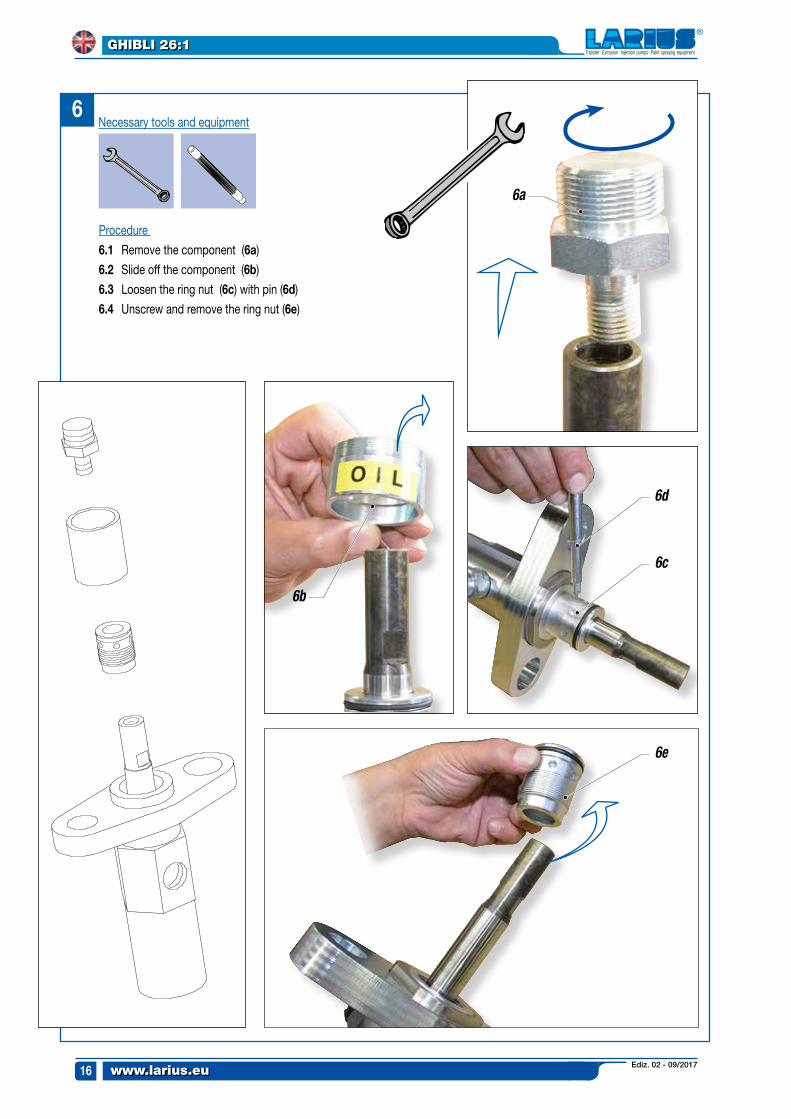
Procedure
6.1 Remove the component (6a)
6.2 Slide off the component (6b)
6.3 Loosen the ring nut (6c) with pin (6d)
6.4 Unscrew and remove the ring nut (6e)
Necessary tools and equipment6
6a
6b
6d
6c
6e
Ediz. 02 - 09/2017 www.larius.eu
GHIBLI 26:1
17
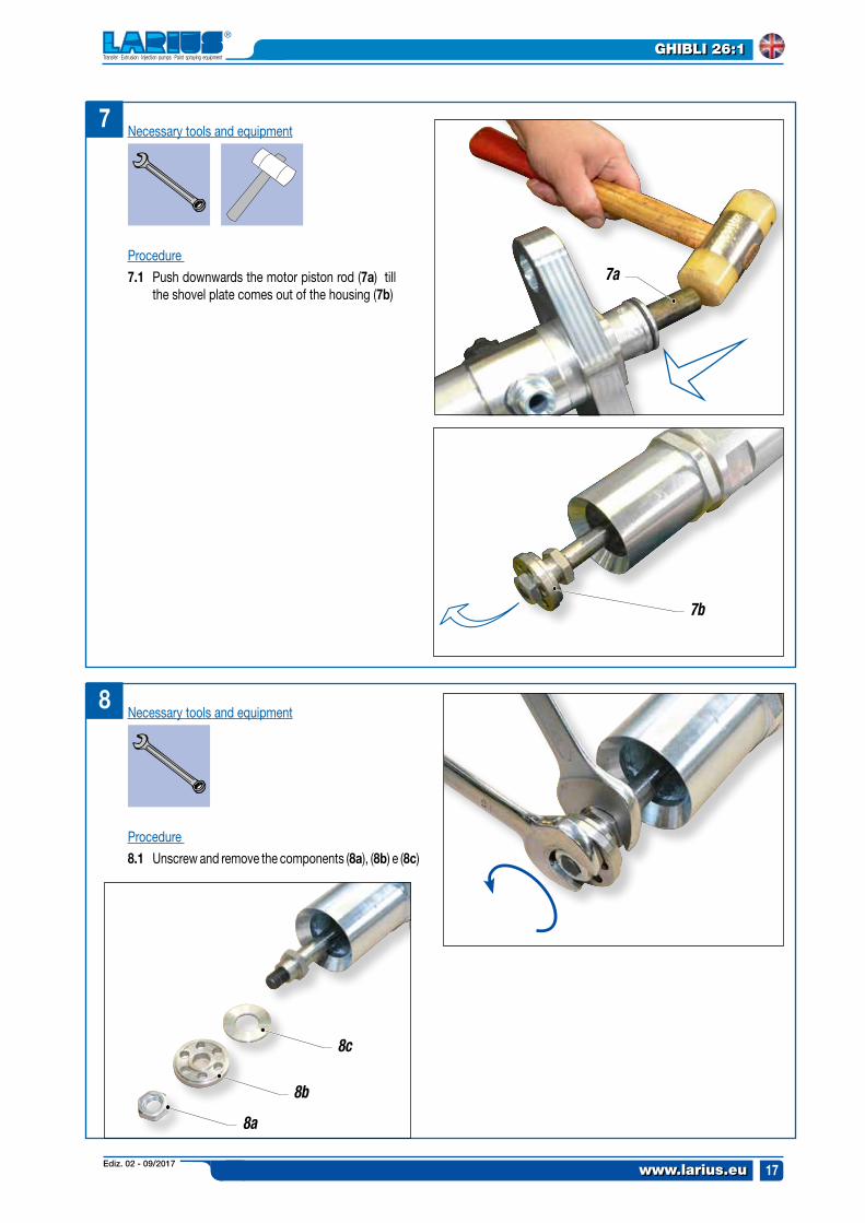
7Necessary tools and equipment
Procedure
7.1 Push downwards the motor piston rod (7a) till the shovel plate comes out of the housing (7b)
7a
7b
8Necessary tools and equipment
8c
8b
8a
Procedure
8.1 Unscrew and remove the components (8a), (8b) e (8c)
Ediz. 02 - 09/2017www.larius.eu
GHIBLI 26:1
18
9
9a
9a
9c
9b
10
10b
10a
10c
10d
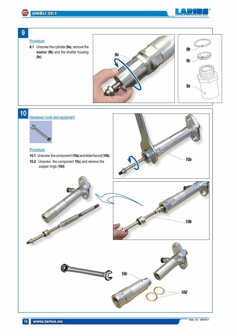
Procedure
10.1 Unscrew the component (10a) and slide the rod (10b)
10.2 Unscrew the component 10c) and remove the copper rings (10d)
Necessary tools and equipment
Procedure
9.1 Unscrew the cylinder (9a), remove the washer (9b) and the shutter housing (9c)
Ediz. 02 - 09/2017 www.larius.eu
GHIBLI 26:1
19
11a11
CLEANER
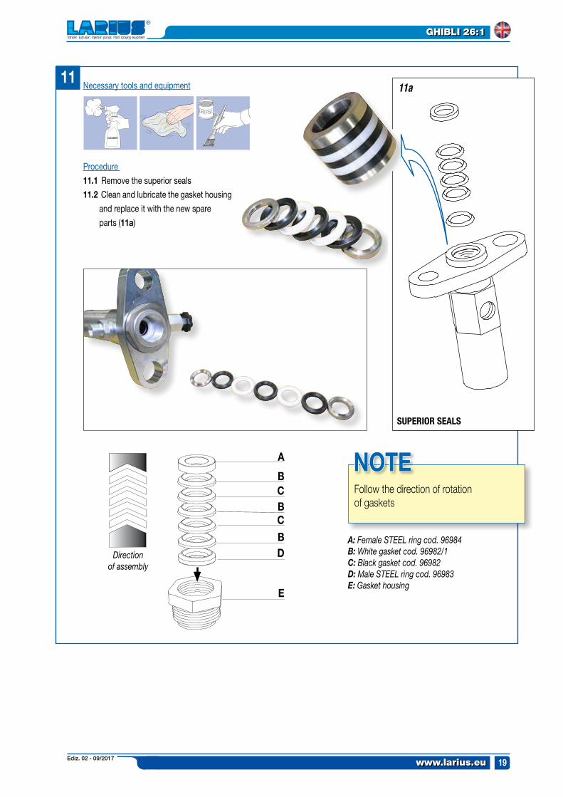
Direction of assembly
A
BCBC
BD
e
A: Female steel ring cod. 96984B: White gasket cod. 96982/1C: Black gasket cod. 96982D: Male steel ring cod. 96983E: Gasket housing
Follow the direction of rotation of gaskets
NOTe
SUPERIOR SEALS
Procedure
11.1 Remove the superior seals
11.2 Clean and lubricate the gasket housing
and replace it with the new spare
parts (11a)
Necessary tools and equipment
Ediz. 02 - 09/2017www.larius.eu
GHIBLI 26:1
20
1212a
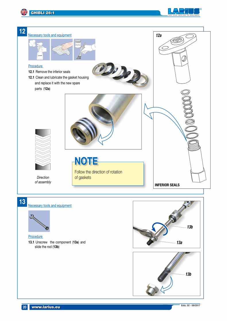
Direction of assembly
CLEANER
Follow the direction of rotation of gaskets
NOTe
13a
13b
13b
INFERIOR SEALS
Procedure
12.1 Remove the inferior seals
12.1 Clean and lubricate the gasket housing
and replace it with the new spare
parts (12a)
Necessary tools and equipment
13
Procedure
13.1 Unscrew the component (13a) and slide the rod (13b)
Necessary tools and equipment
Ediz. 02 - 09/2017 www.larius.eu
GHIBLI 26:1
21
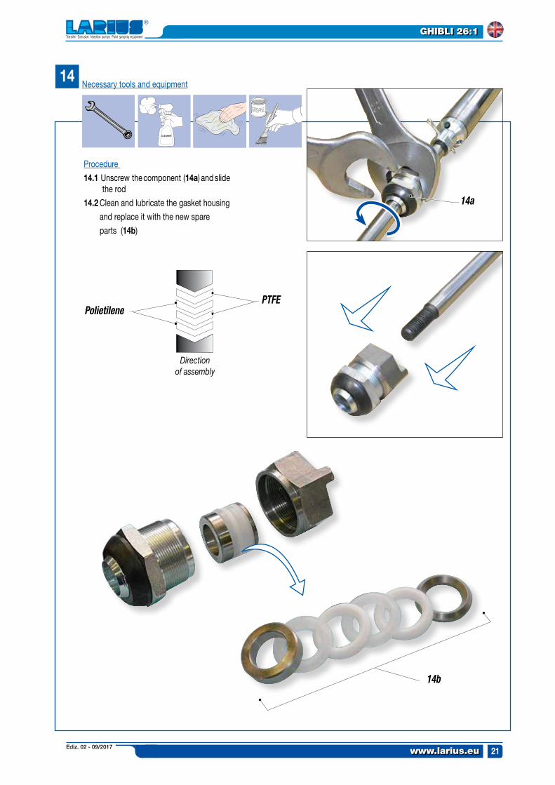
Direction of assembly
14
CLEANER
14a
14b
PTFEPolietilene
Procedure
14.1 Unscrew the component (14a) and slide the rod
14.2 Clean and lubricate the gasket housing
and replace it with the new spare
parts (14b)
Necessary tools and equipment
Ediz. 02 - 09/2017www.larius.eu
GHIBLI 26:1
22
CLEANER
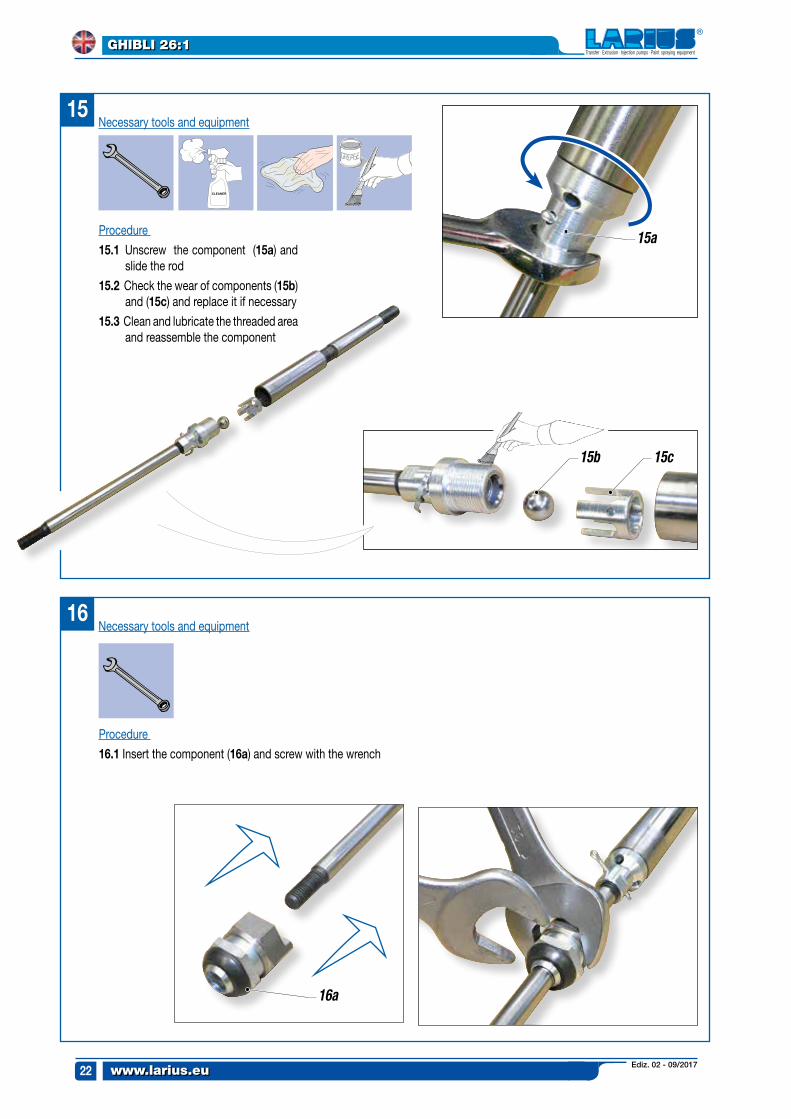
15
15a
16a
15b 15c
Procedure
15.1 Unscrew the component (15a) and slide the rod
15.2 Check the wear of components (15b) and (15c) and replace it if necessary
15.3 Clean and lubricate the threaded area and reassemble the component
Necessary tools and equipment
16
Procedure
16.1 Insert the component (16a) and screw with the wrench
Necessary tools and equipment
Ediz. 02 - 09/2017 www.larius.eu
GHIBLI 26:1
23
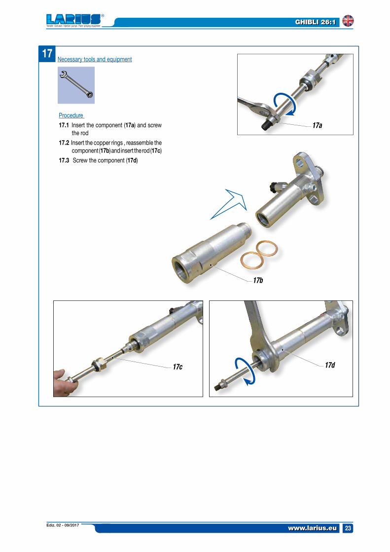
17a
17
17c 17d
17b
Procedure
17.1 Insert the component (17a) and screw the rod
17.2 Insert the copper rings , reassemble the component (17b) and insert the rod (17c)
17.3 Screw the component (17d)
Necessary tools and equipment
Ediz. 02 - 09/2017www.larius.eu
GHIBLI 26:1
24
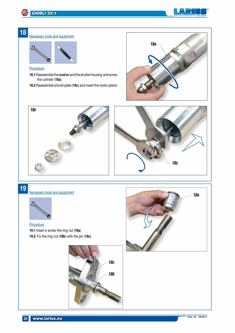
19
18a
18
18c
18c
18a
18c
18b
Necessary tools and equipment
Procedure
19.1 Insert e screw the ring nut (18a)
19.2 Fix the ring nut (18b) with the pin (18c)
Procedure
18.1 Reassemble the washer and the shutter housing and screw the cylinder (18a)
18.2 Reassemble shovel plate (18c) and insert the motor piston
Necessary tools and equipment
Ediz. 02 - 09/2017 www.larius.eu
GHIBLI 26:1
25
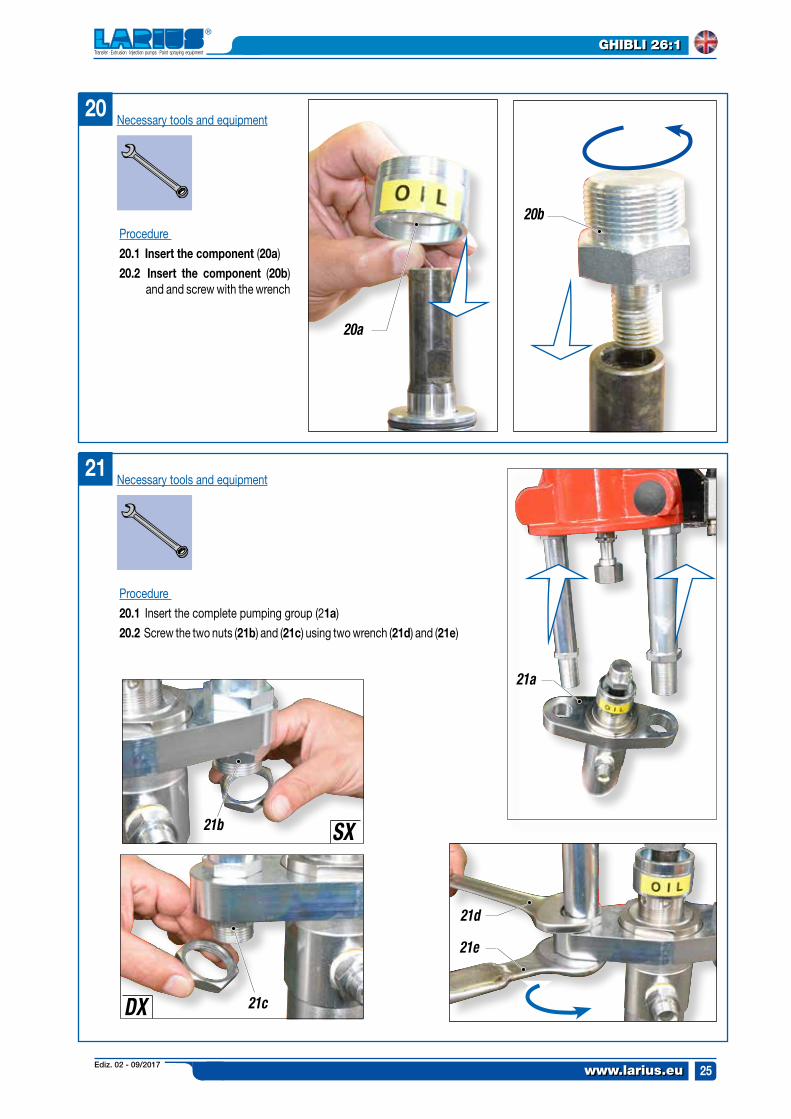
20
20a
20b
21
21b
21c
21e
21d
SX
DX
21a
Procedure
20.1 Insert the component (20a)
20.2 Insert the component (20b) and and screw with the wrench
Necessary tools and equipment
Procedure
20.1 Insert the complete pumping group (21a)
20.2 Screw the two nuts (21b) and (21c) using two wrench (21d) and (21e)
Necessary tools and equipment
Ediz. 02 - 09/2017www.larius.eu
GHIBLI 26:1
26
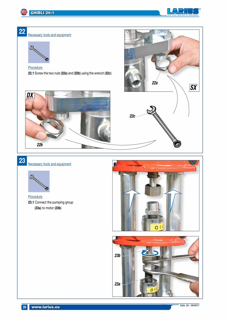
22
22c
22a
22b
SXDX
23
23b
23a
Necessary tools and equipment
Procedure
22.1 Screw the two nuts (22a) and (22b) using the wrench (22c)
Necessary tools and equipment
Procedure
23.1 Connect the pumping group
(23a) to motor (23b)
Ediz. 02 - 09/2017 www.larius.eu
GHIBLI 26:1
27
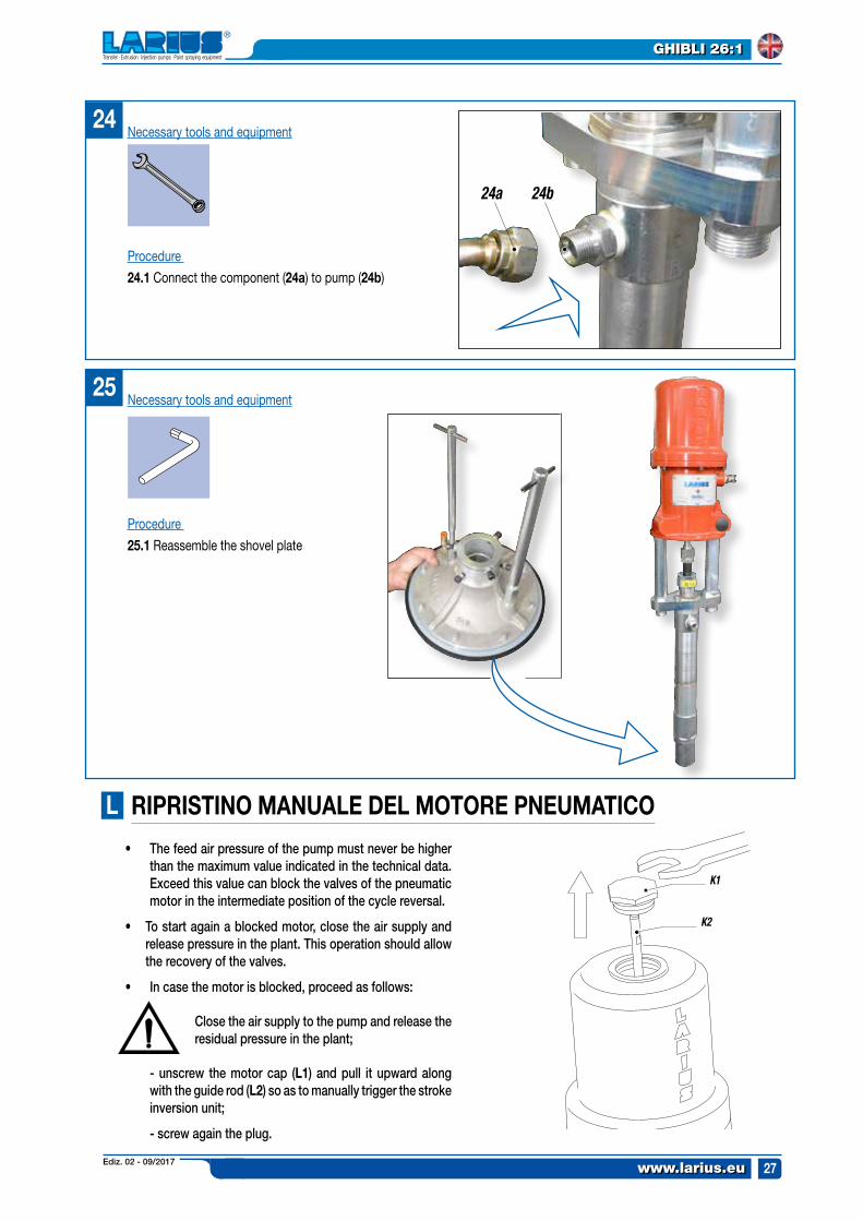
25
24
24a 24b
K1
K2
Procedure
24.1 Connect the component (24a) to pump (24b)
Necessary tools and equipment
Procedure
25.1 Reassemble the shovel plate
Necessary tools and equipment
L rIprIsTINO MANUALe DeL MOTOre pNeUMATICO
• The feed air pressure of the pump must never be higher than the maximum value indicated in the technical data. Exceed this value can block the valves of the pneumatic motor in the intermediate position of the cycle reversal.
• Tostartagainablockedmotor,closetheairsupplyandrelease pressure in the plant. This operation should allow the recovery of the valves.
• Incasethemotorisblocked,proceedasfollows:
Close the air supply to the pump and release the residual pressure in the plant;
- unscrew the motor cap (L1) and pull it upward along with the guide rod (L2) so as to manually trigger the stroke inversion unit;
- screw again the plug.
Ediz. 02 - 09/2017www.larius.eu
GHIBLI 26:1
28
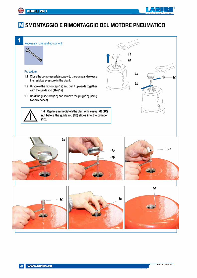
1a
1a
1b
1c
1b
M
1c
1d
1c1c
1e
1a
1b
1
sMONTAGGIO e rIMONTAGGIO DeL MOTOre pNeUMATICO
Procedure
1.1 Close the compressed air supply to the pump and release the residual pressure in the plant.
1.2 Unscrew the motor cap (1a) and pull it upwards together with the guide rod (1b) (1e)
1.3 Hold the guide rod (1b) and remove the plug (1a) (using two wrenches).
Necessary tools and equipment
1.4 replace immediately the plug with a usual M8 (1C) nut before the guide rod (1B) slides into the cylinder (1D).
Ediz. 02 - 09/2017 www.larius.eu
GHIBLI 26:1
29
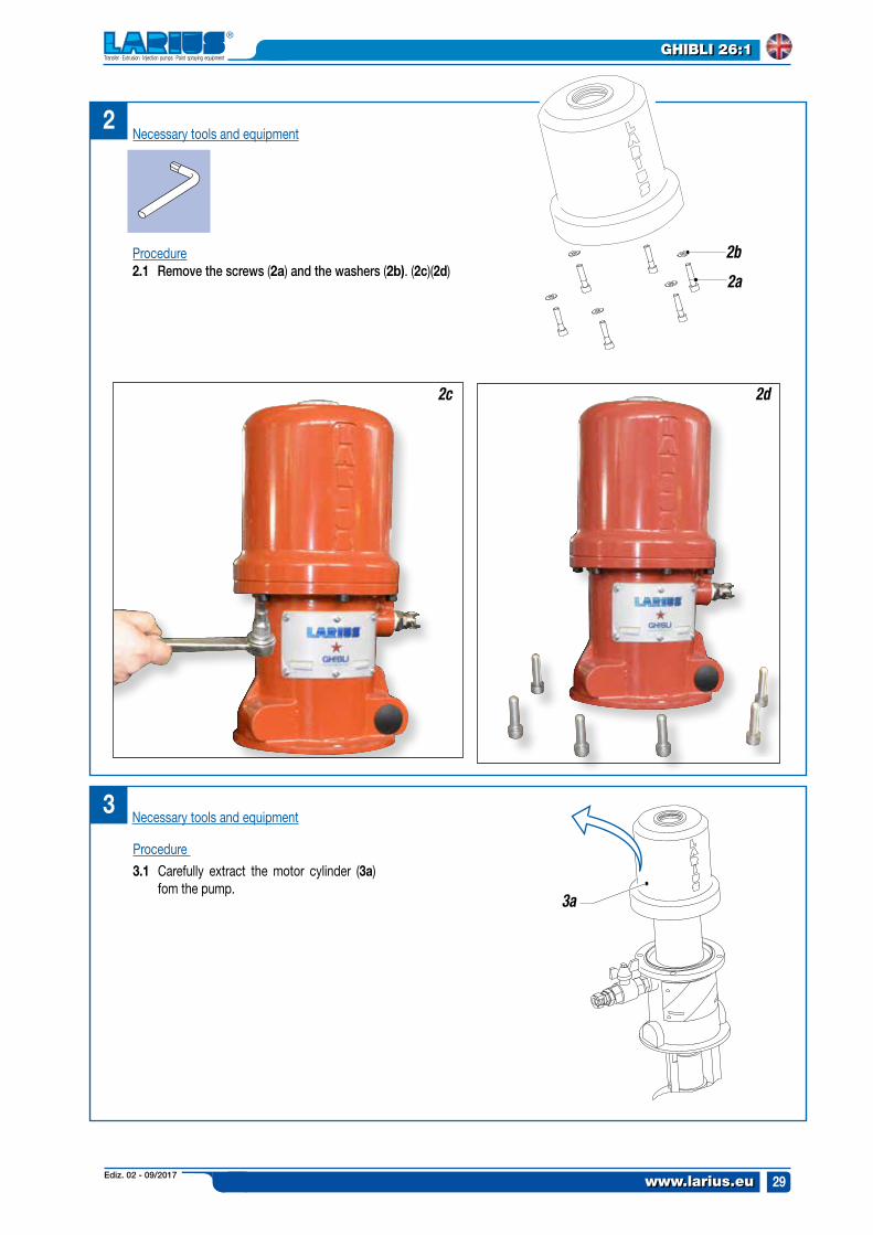
2Necessary tools and equipment
Procedure2.1 Remove the screws (2a) and the washers (2b). (2c)(2d)
2b
2a
2c 2d
3
3a
Procedure
3.1 Carefully extract the motor cylinder (3a) fom the pump.
Necessary tools and equipment
Ediz. 02 - 09/2017www.larius.eu
GHIBLI 26:1
30
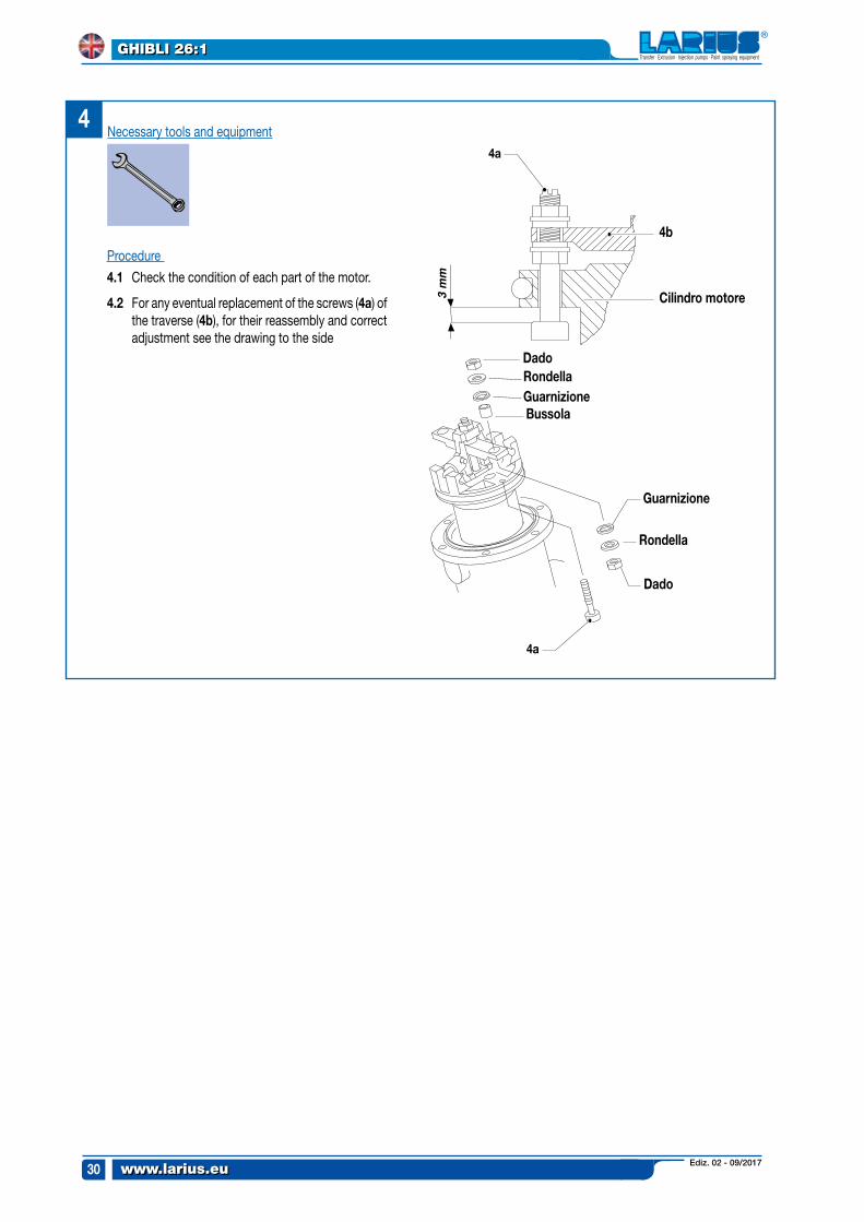
3 m
m
4a
DadorondellaGuarnizioneBussola
rondella
Guarnizione
Dado
4b
Cilindro motore
44a
Procedure
4.1 Check the condition of each part of the motor.
4.2 For any eventual replacement of the screws (4a) of the traverse (4b), for their reassembly and correct adjustment see the drawing to the side
Necessary tools and equipment
Ediz. 02 - 09/2017 www.larius.eu
GHIBLI 26:1
31
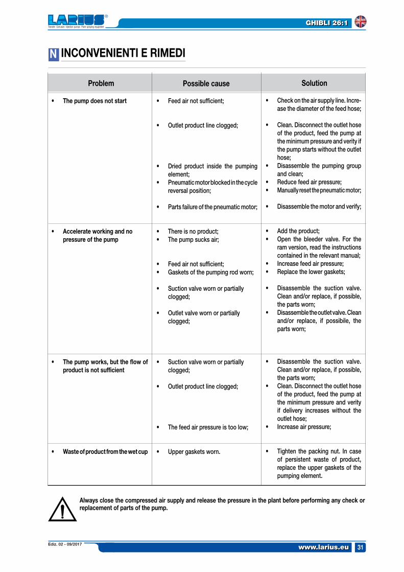
N INCONVeNIeNTI e rIMeDI
solutionpossible causeproblem
• The pump does not start
• Accelerate working and no pressure of the pump
• The pump works, but the flow of product is not sufficient
• Waste of product from the wet cup
• Feed air not sufficient;
• Outlet product line clogged;
• Dried product inside the pumping element;
• Pneumatic motor blocked in the cycle reversal position;
• Parts failure of the pneumatic motor;
• There is no product; • The pump sucks air;
• Feed air not sufficient;• Gaskets of the pumping rod worn;
• Suction valve worn or partially clogged;
• Outlet valve worn or partially clogged;
• Suction valve worn or partially clogged;
• Outlet product line clogged;
• The feed air pressure is too low;
• Upper gaskets worn.
• Check on the air supply line. Incre-ase the diameter of the feed hose;
• Clean. Disconnect the outlet hose of the product, feed the pump at the minimum pressure and verity if the pump starts without the outlet hose;
• Disassemble the pumping group and clean;
• Reduce feed air pressure;• Manually reset the pneumatic motor;
• Disassemble the motor and verify;
• Add the product;• Open the bleeder valve. For the
ram version, read the instructions contained in the relevant manual;
• Increase feed air pressure;• Replace the lower gaskets;
• Disassemble the suction valve. Clean and/or replace, if possible, the parts worn;
• Disassemble the outlet valve. Clean and/or replace, if possibile, the parts worn;
• Disassemble the suction valve. Clean and/or replace, if possible, the parts worn;
• Clean. Disconnect the outlet hose of the product, feed the pump at the minimum pressure and verity if delivery increases without the outlet hose;
• Increase air pressure;
• Tighten the packing nut. In case of persistent waste of product, replace the upper gaskets of the pumping element.
Always close the compressed air supply and release the pressure in the plant before performing any check or replacement of parts of the pump.

Ediz. 02 - 09/2017www.larius.eu
GHIBLI 26:1
32
White page
intentionally

Ediz. 02 - 09/2017 www.larius.eu
GHIBLI 26:1
33
O
p
pArTICOLArI DI rICAMBIO
Complete pumping motor
pag. 34
spare part list pump group
pag. 36
Ediz. 02 - 09/2017www.larius.eu
GHIBLI 26:1
34
31
12
3
456 7
8
141516
19
21
22
23
24
25
26
32
29
30
33
34353637
27
28
20
1817
91011121311109
29
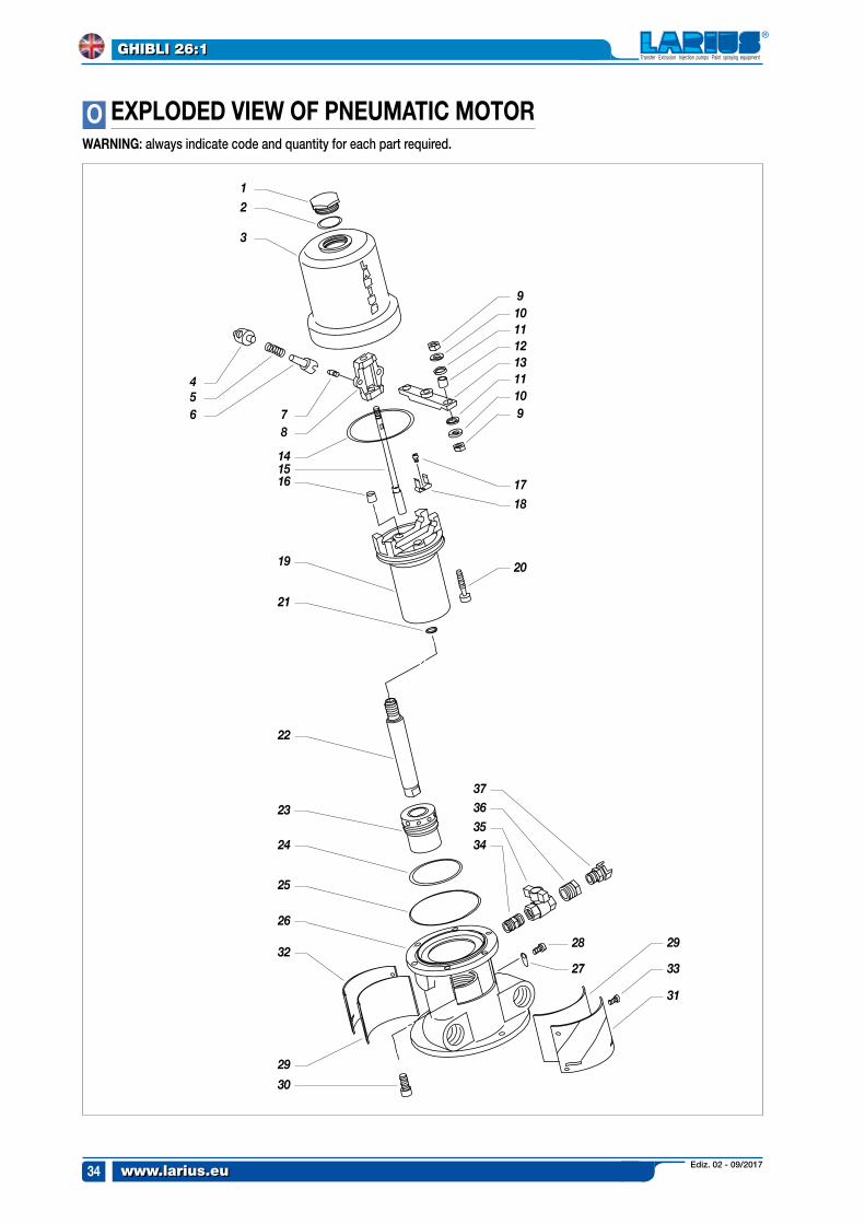
eXpLODeD VIeW OF pNeUMATIC MOTOrOWArNING: always indicate code and quantity for each part required.
Ediz. 02 - 09/2017 www.larius.eu
GHIBLI 26:1
35
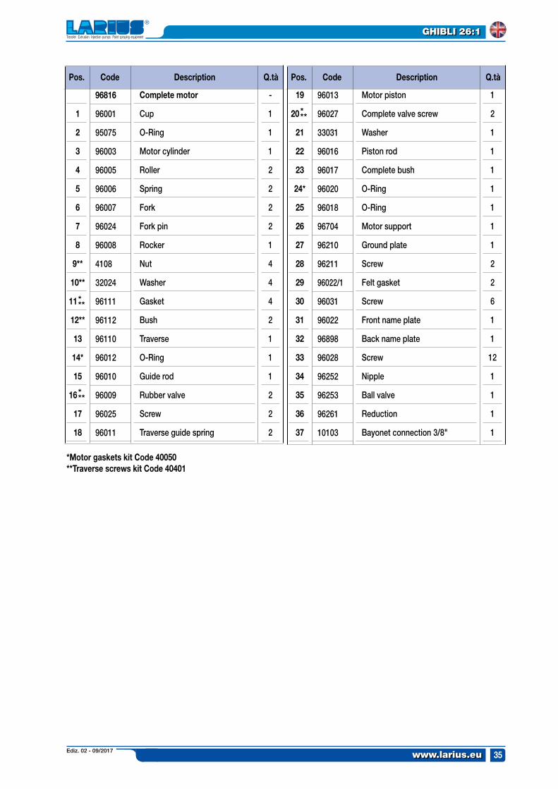
pos. pos.Code CodeDescription DescriptionQ.tà Q.tà
Complete motor
Cup
O-Ring
Motor cylinder
Roller
Spring
Fork
Fork pin
Rocker
Nut
Washer
Gasket
Bush
Traverse
O-Ring
Guide rod
Rubber valve
Screw
Traverse guide spring
Motor piston
Complete valve screw
Washer
Piston rod
Complete bush
O-Ring
O-Ring
Motor support
Ground plate
Screw
Felt gasket
Screw
Front name plate
Back name plate
Screw
Nipple
Ball valve
Reduction
Bayonet connection 3/8"
-
1
1
1
2
2
2
2
1
4
4
4
2
1
1
1
2
2
2
1
2
1
1
1
1
1
1
1
2
2
6
1
1
12
1
1,
1
1
1
2
3
4
5
6
7
8
9**
10**
11
12**
13
14*
15
16
17
18
19
20
21
22
23
24*
25
26
27
28
29
30
31
32
33
34
35
36
37
96816
96001
95075
96003
96005
96006
96007
96024
96008
4108
32024
96111
96112
96110
96012
96010
96009
96025
96011
96013
96027
33031
96016
96017
96020
96018
96704
96210
96211
96022/1
96031
96022
96898
96028
96252
96253
96261
10103
*Motor gaskets kit Code 40050**Traverse screws kit Code 40401
***
***
***
Ediz. 02 - 09/2017www.larius.eu
GHIBLI 26:1
36
34
35
3637
41
29
3132
33
26
43
44
45
46
47
30
42
9
6
7
8
17
19
20
22
21
26
27
1
2
3
5
10
13
16
2324
25
28
4
11
12
1838
3839
3940
1415
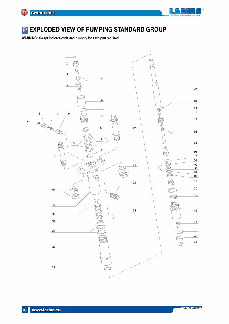
pWArNING: always indicate code and quantity for each part required.
eXpLODeD VIeW OF pUMpING sTANDArD GrOUp
Ediz. 02 - 09/2017 www.larius.eu
GHIBLI 26:1
37
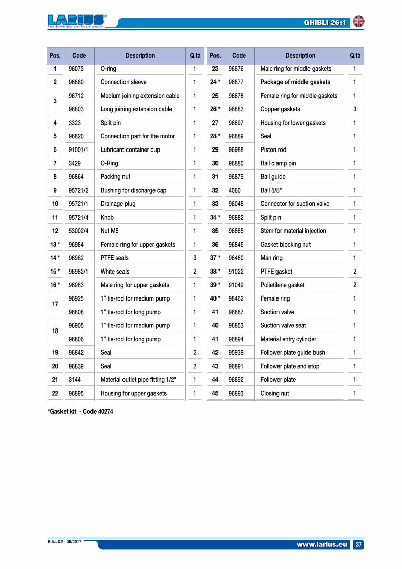
pos. pos.Code CodeDescription DescriptionQ.tà Q.tà
O-ring
Connection sleeve
Medium joining extension cable
Long joining extension cable
Split pin
Connection part for the motor
Lubricant container cup
O-Ring
Packing nut
Bushing for discharge cap
Drainage plug
Knob
Nut M8
Female ring for upper gaskets
PTFE seals
White seals
Male ring for upper gaskets
1” tie-rod for medium pump
1” tie-rod for long pump
1” tie-rod for medium pump
1” tie-rod for long pump
Seal
Seal
Material outlet pipe fitting 1/2"
Housing for upper gaskets
Male ring for middle gaskets
package of middle gaskets
Female ring for middle gaskets
Copper gaskets
Housing for lower gaskets
Seal
Piston rod
Ball clamp pin
Ball guide
Ball 5/8"
Connector for suction valve
Split pin
Stem for material injection
Gasket blocking nut
Man ring
PTFE gasket
Polietilene gasket
Female ring
Suction valve
Suction valve seat
Material entry cylinder
Follower plate guide bush
Follower plate end stop
Follower plate
Closing nut
1
1
1
1
1
1
1
1
1
1
1
1
1
1
3
2
1
1
1
1
1
2
2
1
1
1
1
1
3
1
1
1
1
1
1
1
1
1
1
1
2
2
1
1
1
1
1
1
1
1
1
2
3
4
5
6
7
8
9
10
11
12
13 *
14 *
15 *
16 *
17
18
19
20
21
22
23
24 *
25
26 *
27
28 *
29
30
31
32
33
34 *
35
36
37 *
38 *
39 *
40 *
41
40
41
42
43
44
45
96073
96860
96712
96803
3323
96820
91001/1
3429
96864
95721/2
95721/1
95721/4
53002/4
96984
96982
96982/1
96983
96925
96808
96905
96806
96842
96839
3144
96895
96876
96877
96878
96883
96897
96889
96988
96880
96879
4060
96045
96882
96885
96845
98460
91022
91049
98462
96887
96853
96894
95939
96891
96892
96893
*Gasket kit - Code 40274
Ediz. 02 - 09/2017www.larius.eu
GHIBLI 26:1
38
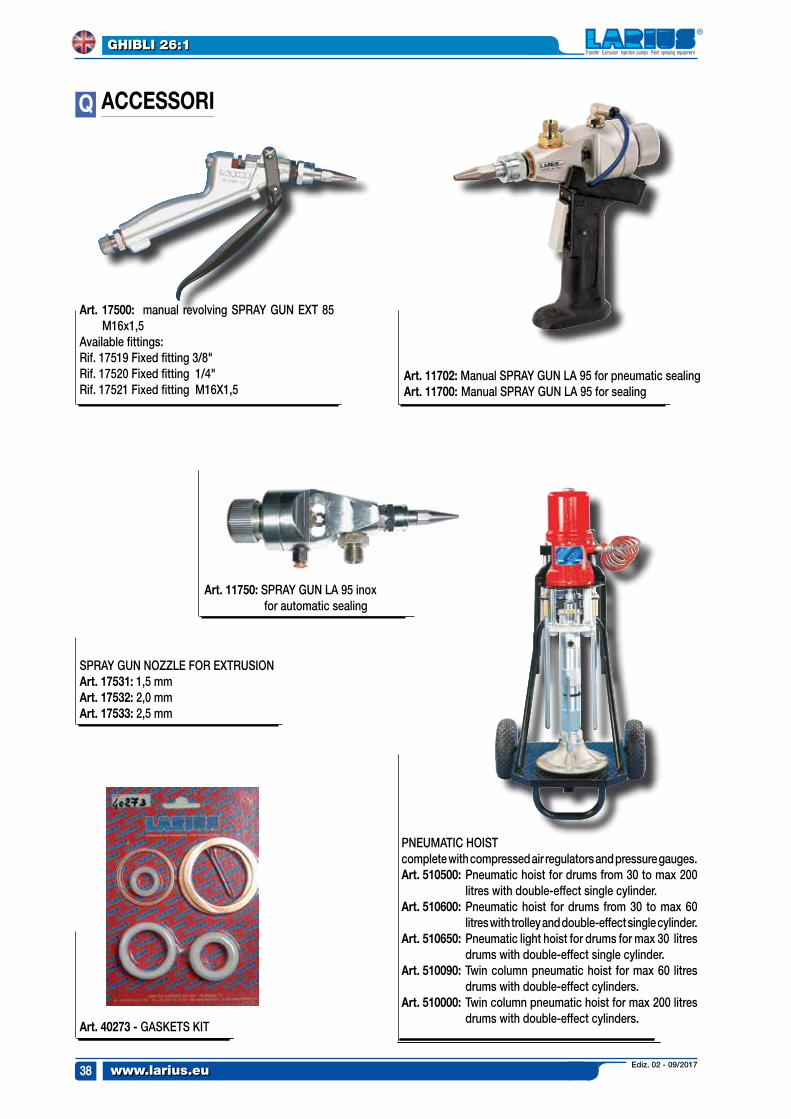
ACCessOrIQ
Art. 17500: manual revolving SPRAY GUN EXT 85 M16x1,5
Available fittings:Rif. 17519 Fixed fitting 3/8"Rif. 17520 Fixed fitting 1/4"Rif. 17521 Fixed fitting M16X1,5
Art. 11750: SPRAY GUN LA 95 inox for automatic sealing
Art. 11702: Manual SPRAY GUN LA 95 for pneumatic sealing Art. 11700: Manual SPRAY GUN LA 95 for sealing
Art. 40273 - GASKETS KIT
PNEUMATIC HOIST complete with compressed air regulators and pressure gauges.Art. 510500: Pneumatic hoist for drums from 30 to max 200
litres with double-effect single cylinder.Art. 510600: Pneumatic hoist for drums from 30 to max 60
litres with trolley and double-effect single cylinder.Art. 510650: Pneumatic light hoist for drums for max 30 litres
drums with double-effect single cylinder.Art. 510090: Twin column pneumatic hoist for max 60 litres
drums with double-effect cylinders.Art. 510000: Twin column pneumatic hoist for max 200 litres
drums with double-effect cylinders.
SPRAY GUN NOZZLE FOR EXTRUSIONArt. 17531: 1,5 mmArt. 17532: 2,0 mmArt. 17533: 2,5 mm
Ediz. 02 - 09/2017 www.larius.eu
GHIBLI 26:1
39
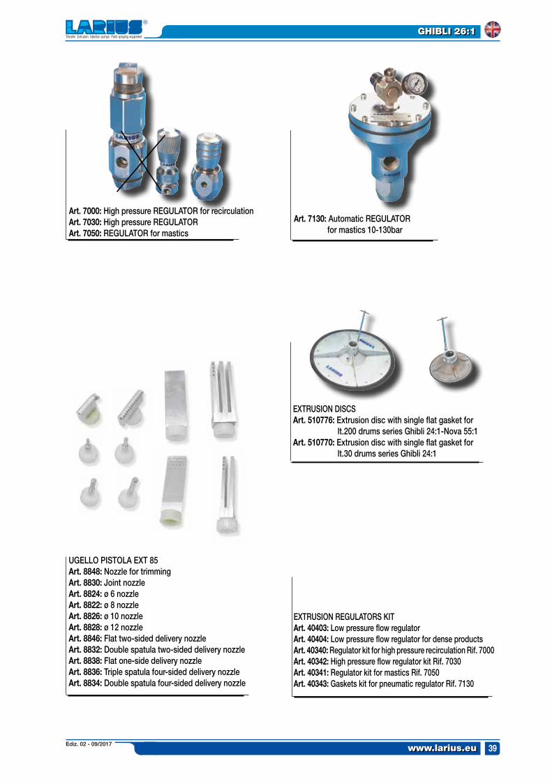
EXTRUSION DISCSArt. 510776: Extrusion disc with single flat gasket for lt.200 drums series Ghibli 24:1-Nova 55:1Art. 510770: Extrusion disc with single flat gasket for lt.30 drums series Ghibli 24:1
Art. 7000: High pressure REGULATOR for recirculation Art. 7030: High pressure REGULATOR Art. 7050: REGULATOR for mastics
Art. 7130: Automatic REGULATOR for mastics 10-130bar
EXTRUSION REGULATORS KITArt. 40403: Low pressure flow regulator Art. 40404: Low pressure flow regulator for dense productsArt. 40340: Regulator kit for high pressure recirculation Rif. 7000Art. 40342: High pressure flow regulator kit Rif. 7030Art. 40341: Regulator kit for mastics Rif. 7050Art. 40343: Gaskets kit for pneumatic regulator Rif. 7130
UGELLO PISTOLA EXT 85Art. 8848: Nozzle for trimmingArt. 8830: Joint nozzleArt. 8824: ø 6 nozzleArt. 8822: ø 8 nozzleArt. 8826: ø 10 nozzleArt. 8828: ø 12 nozzle Art. 8846: Flat two-sided delivery nozzleArt. 8832: Double spatula two-sided delivery nozzleArt. 8838: Flat one-side delivery nozzleArt. 8836: Triple spatula four-sided delivery nozzleArt. 8834: Double spatula four-sided delivery nozzle
Ediz. 02 - 09/2017www.larius.eu
GHIBLI 26:1
40
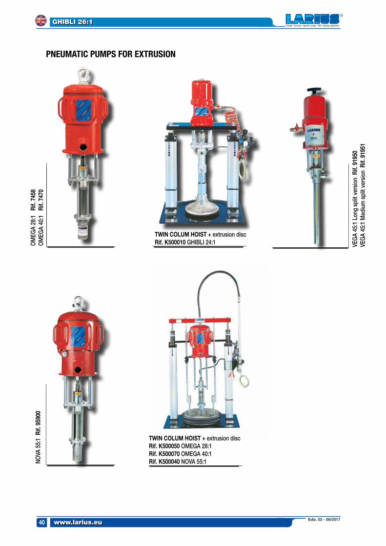
PNEUMATIC PUMPS FOR EXTRUSION
NOVA
55:
1 r
if. 9
5900
OM
EGA
28:1
ri
f. 74
58
OM
EGA
40:1
ri
f. 74
70
VEG
A 45
:1 L
ong
split
ver
sion
rif.
919
50VE
GA
45:1
Med
ium
spl
it ve
rsio
n r
if. 9
1951
TWIN COLUM HOIsT + extrusion discrif. K500010 GHIBLI 24:1
TWIN COLUM HOIsT + extrusion discrif. K500050 OMEGA 28:1 rif. K500070 OMEGA 40:1 rif. K500040 NOVA 55:1

pAINT sprAYING eQUIpMeNT
Innovation.The real kind.

Made in Italy 1969
LARIUS srlVia Antonio Stoppani 21 - 23801 Calolziocorte (LC) ITALY
TEL. +39 0341 621152 - Fax +39 0341 621243 - [email protected]
www.larius.eu