geze accessories for door closers from ... 19 10 36 33 35 36 6 6 33 38,5 s s s fig. 05-1 fig. 05-2...
TRANSCRIPT
B E W E G U N G M I T S Y S T E M
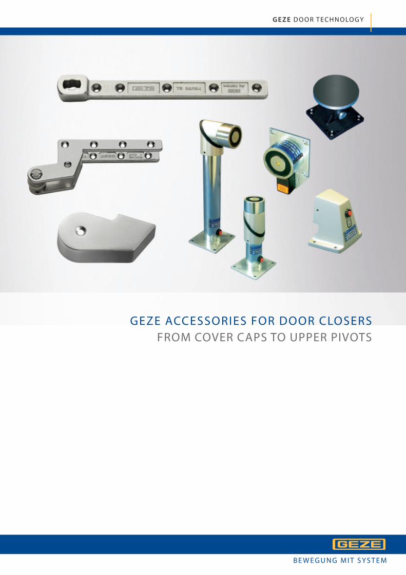
GEZE ACCESSORIES FOR DOOR CLOSERS
FROM COVER CAPS TO UPPER PIVOTS
G E Z E D O O R T E C H N O LO G Y
3
Acc
ess
ori
es
for
do
or
clo
sers
GE
ZE
Do
or
Tech
no
log
y
Accessories for door closers
From cover caps to upper pivots
GEZE ACCESSORIES FOR DOOR CLOSERS
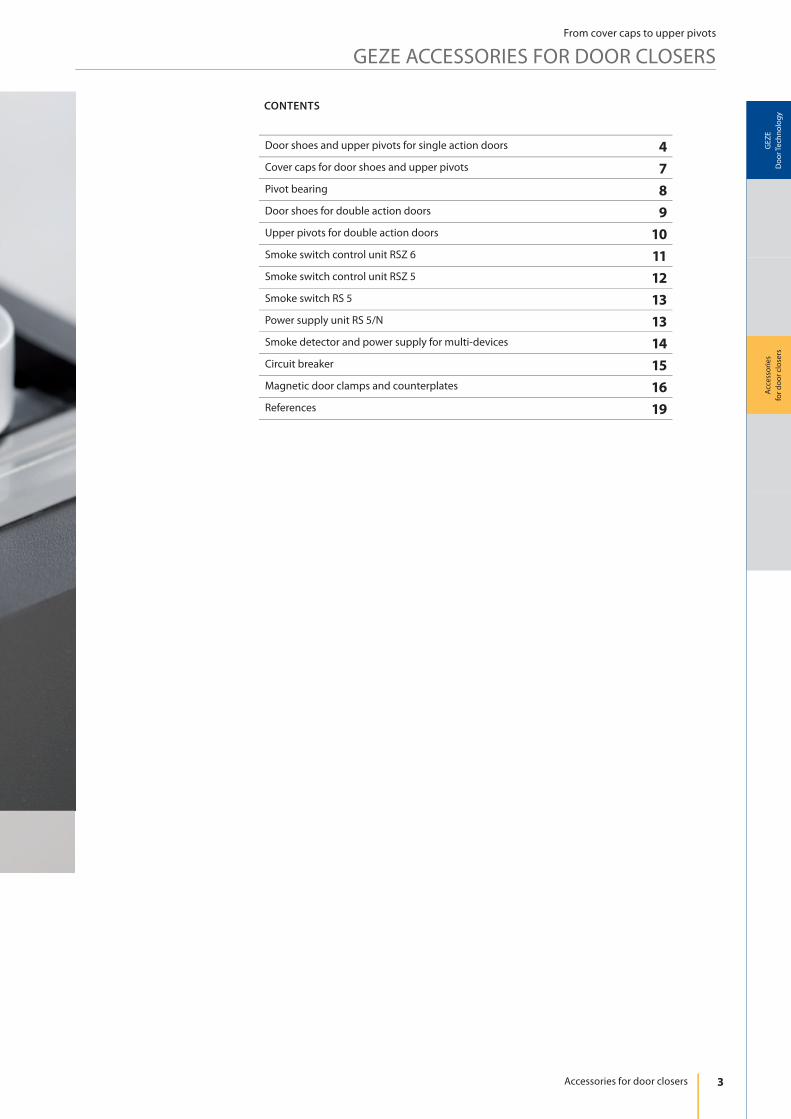
Door shoes and upper pivots for single action doors 4
Cover caps for door shoes and upper pivots 7
Pivot bearing 8
Door shoes for double action doors 9
Upper pivots for double action doors 10
Smoke switch control unit RSZ 6 11
Smoke switch control unit RSZ 5 12
Smoke switch RS 5 13
Power supply unit RS 5/N 13
Smoke detector and power supply for multi-devices 14
Circuit breaker 15
Magnetic door clamps and counterplates 16
References 19
CONTENTS
4
GERMANY
MADE IN
26
40
210
10
16
19
56
52
19
10
24
217
48 48 48 48
33
45
20
53
46 46 46
33
167
19
,5
S
77
SS
45
a
b
c
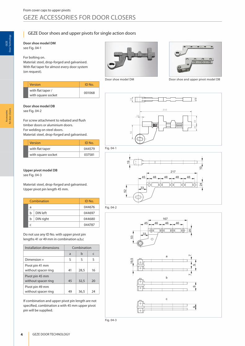
Fig. 04-1
Fig. 04-2
Fig. 04-3
Acc
ess
ori
es
for
do
or
clo
sers
GE
ZE
Do
or
Tech
no
log
y
GEZE DOOR TECHNOLOGY
From cover caps to upper pivots
GEZE ACCESSORIES FOR DOOR CLOSERS
GEZE Door shoes and upper pivots for single action doors
Door shoe model DM
see Fig. 04-1
For bolting on.
Material: steel, drop-forged and galvanised.
With ! at taper for almost every door system
(on request).
Door shoe model DB
see Fig. 04-2
For screw attachment to rebated and ! ush
timber doors or aluminium doors.
For welding on steel doors.
Material: steel, drop-forged and galvanised.
Upper pivot model DB
see Fig. 04-3
Material: steel, drop-forged and galvanised.
Upper pivot pin length 45 mm.
Do not use any ID No. with upper pivot pin
lengths 41 or 49 mm in combination a,b,c
If combination and upper pivot pin length are not
speci" ed, combination a with 45 mm upper pivot
pin will be supplied.
Version ID No.
with ! at taper /
with square socket001068
Version ID No.
with ! at taper 044579
with square socket 037581
Combination ID No.
a 044676
b DIN left 044697
b DIN right 044680
c 044787
Installation dimensions Combination
a b c
Dimension = S S S
Pivot pin 41 mm
without spacer ring 41 28,5 16
Pivot pin 45 mm
without spacer ring 45 32,5 20
Pivot pin 49 mm
without spacer ring 49 36,5 24
Door shoe model DM Door shoe and upper pivot model DB
5
19
10
36
33 35
36
66
33 38,5
SS
S
Fig. 05-1
Fig. 05-2
Acc
ess
ori
es
for
do
or
clo
sers
GE
ZE
Do
or
Tech
no
log
y
Accessories for door closers
From cover caps to upper pivots
GEZE ACCESSORIES FOR DOOR CLOSERS
GEZE Door shoes and upper pivots for single action doors
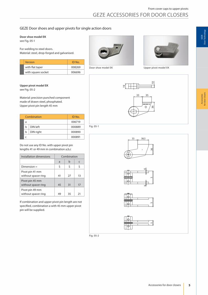
Door shoe model EK
see Fig. 05-1
For welding to steel doors.
Material: steel, drop-forged and galvanised.
Upper pivot model EK
see Fig. 05-2
Material: precision punched component
made of drawn steel, phosphated.
Upper pivot pin length 45 mm
Do not use any ID No. with upper pivot pin
lengths 41 or 49 mm in combination a,b,c
If combination and upper pivot pin length are not
speci! ed, combination a with 45 mm upper pivot
pin will be supplied.
Version ID No.
with " at taper 008269
with square socket 006696
Combination ID No.
a 006719
b DIN left 000889
b DIN right 000890
c 000891
Installation dimensions Combination
a b c
Dimension = S S S
Pivot pin 41 mm
without spacer ring 41 27 13
Pivot pin 45 mm
without spacer ring 45 31 17
Pivot pin 49 mm
without spacer ring 49 35 21
Door shoe model EK Upper pivot model EK
6
78
19
,5
77
33
40
SS
S
a
b
c
Fig. 06-2
Fig. 06-1
Acc
ess
ori
es
for
do
or
clo
sers
GE
ZE
Do
or
Tech
no
log
y
GEZE DOOR TECHNOLOGY
From cover caps to upper pivots
GEZE ACCESSORIES FOR DOOR CLOSERS
GEZE Door shoes and upper pivot for single action doors
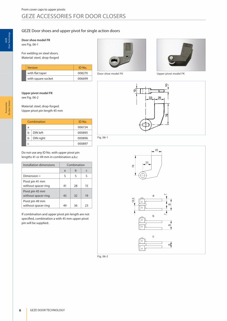
Door shoe model FK
see Fig. 06-1
For welding on steel doors.
Material: steel, drop-forged
Upper pivot model FK
see Fig. 06-2
Material: steel, drop-forged.
Upper pivot pin length 45 mm
Do not use any ID No. with upper pivot pin
lengths 41 or 49 mm in combination a,b,c
If combination and upper pivot pin length are not
speci! ed, combination a with 45 mm upper pivot
pin will be supplied.
Version ID No.
with " at taper 008270
with square socket 006699
Combination ID No.
a 006724
b DIN left 000895
b DIN right 000896
c 000897
Installation dimensions Combination
a b c
Dimension = S S S
Pivot pin 41 mm
without spacer ring 41 28 15
Pivot pin 45 mm
without spacer ring 45 32 19
Pivot pin 49 mm
without spacer ring 49 36 23
Door shoe model FK Upper pivot model FK
7
Fig. 07-1
Fig. 07-2
Acc
ess
ori
es
for
do
or
clo
sers
GE
ZE
Do
or
Tech
no
log
y
Accessories for door closers
From cover caps to upper pivots
GEZE ACCESSORIES FOR DOOR CLOSERS
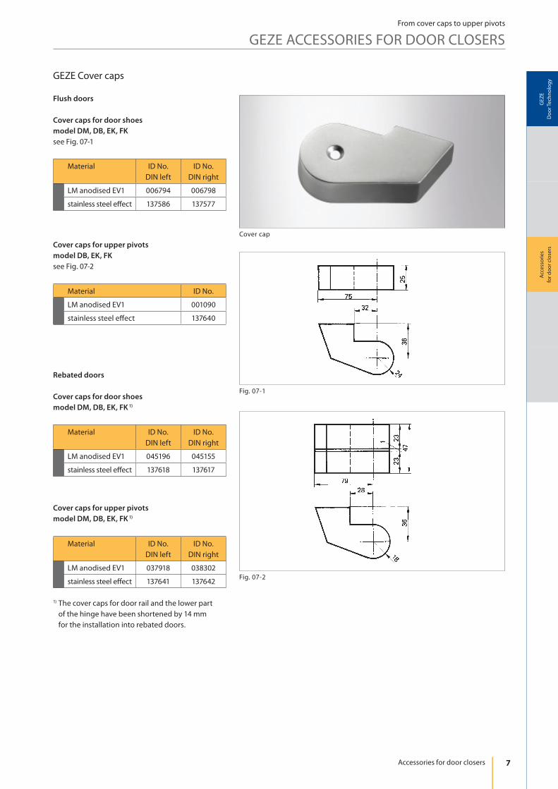
GEZE Cover caps
Flush doors
Cover caps for door shoes
model DM, DB, EK, FK
see Fig. 07-1
Rebated doors
Cover caps for door shoes
model DM, DB, EK, FK 1)
Cover caps for upper pivots
model DM, DB, EK, FK 1)
Cover caps for upper pivots
model DB, EK, FK
see Fig. 07-2
Material ID No.
DIN left
ID No.
DIN right
LM anodised EV1 006794 006798
stainless steel e! ect 137586 137577
Material ID No.
DIN left
ID No.
DIN right
LM anodised EV1 045196 045155
stainless steel e! ect 137618 137617
Material ID No.
DIN left
ID No.
DIN right
LM anodised EV1 037918 038302
stainless steel e! ect 137641 137642
1) The cover caps for door rail and the lower part
of the hinge have been shortened by 14 mm
for the installation into rebated doors.
Material ID No.
LM anodised EV1 001090
stainless steel e! ect 137640
Cover cap
8
Fig. 09-1
Acc
ess
ori
es
for
do
or
clo
sers
GE
ZE
Do
or
Tech
no
log
y
GEZE DOOR TECHNOLOGY
From cover caps to upper pivots
GEZE ACCESSORIES FOR DOOR CLOSERS
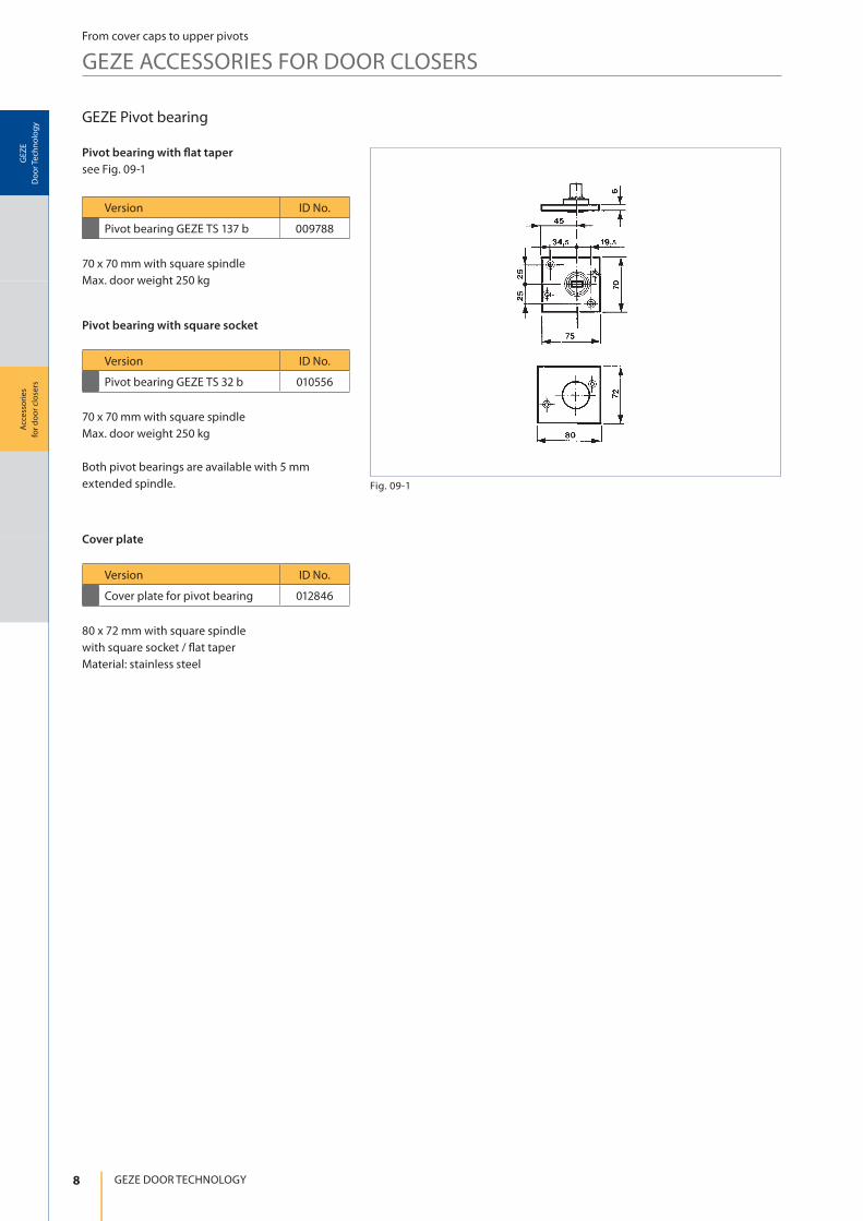
GEZE Pivot bearing
Pivot bearing with � at taper
see Fig. 09-1
Pivot bearing with square socket
Cover plate
70 x 70 mm with square spindle
Max. door weight 250 kg
70 x 70 mm with square spindle
Max. door weight 250 kg
Both pivot bearings are available with 5 mm
extended spindle.
80 x 72 mm with square spindle
with square socket / ! at taper
Material: stainless steel
Version ID No.
Pivot bearing GEZE TS 137 b 009788
Version ID No.
Pivot bearing GEZE TS 32 b 010556
Version ID No.
Cover plate for pivot bearing 012846
9
3020 30 60 60 55
22,590°
ø6,5
30
24
19 10
ø12
Fig. 10-2
Fig. 10-3
Fig. 10-1
Acc
ess
ori
es
for
do
or
clo
sers
GE
ZE
Do
or
Tech
no
log
y
Accessories for door closers
From cover caps to upper pivots
GEZE ACCESSORIES FOR DOOR CLOSERS
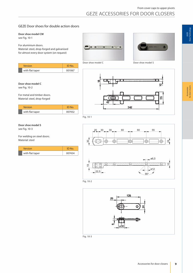
GEZE Door shoes for double action doors
Door shoe model CM
see Fig. 10-1
For aluminium doors.
Material: steel, drop-forged and galvanised
for almost every door system (on request)
Door shoe model C
see Fig. 10-2
For metal and timber doors.
Material: steel, drop-forged
Door shoe model S
see Fig. 10-3
For welding on steel doors.
Material: steel
Version ID No.
with ! at taper 001067
Version ID No.
with ! at taper 007432
Version ID No.
with ! at taper 007434
Door shoe model C Door shoe model S
10
Fig. 11-1
Fig. 11-2
Acc
ess
ori
es
for
do
or
clo
sers
GE
ZE
Do
or
Tech
no
log
y
GEZE DOOR TECHNOLOGY
From cover caps to upper pivots
GEZE ACCESSORIES FOR DOOR CLOSERS
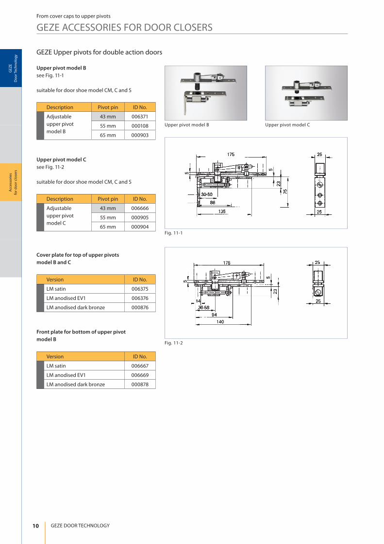
GEZE Upper pivots for double action doors
Upper pivot model B
see Fig. 11-1
suitable for door shoe model CM, C and S
Upper pivot model C
see Fig. 11-2
suitable for door shoe model CM, C and S
Description Pivot pin ID No.
Adjustable
upper pivot
model B
43 mm 006371
55 mm 000108
65 mm 000903
Description Pivot pin ID No.
Adjustable
upper pivot
model C
43 mm 006666
55 mm 000905
65 mm 000904
Cover plate for top of upper pivots
model B and C
Front plate for bottom of upper pivot
model B
Version ID No.
LM satin 006375
LM anodised EV1 006376
LM anodised dark bronze 000876
Version ID No.
LM satin 006667
LM anodised EV1 006669
LM anodised dark bronze 000878
Upper pivot model B Upper pivot model C
11
40
135
306
332
30
12
12
53
Fig. 12-1
BN
BU
NCCOM
NO
RSZ6
ORS142 ORS142
Fig. 12-2
Fig. 12-3
Acc
ess
ori
es
for
do
or
clo
sers
GE
ZE
Do
or
Tech
no
log
y
Accessories for door closers
From cover caps to upper pivots
GEZE ACCESSORIES FOR DOOR CLOSERS
Threaded holes M5Threaded holes M5
ø15, power supply (230 V AC) ø15, opening for
additional connections
2-pole ribbon cable
connection for guide rail
power supply
Potential-free
alarm contact
max. 24 V, 1A
Manual release
button, external
24 V DC
supply
(mains)
1. additional
alarm
2. additional
alarm
Jumper 1 (black)
remove this when connecting
a trip switch to terminals 5 and 6
Jumper 2 (red)
remove this when connecting
additional alarms
Plug-in jumper to be
in position 1-2
24 V DC
for door closer with
hold-open device or
magnetic clamp
230 V AC
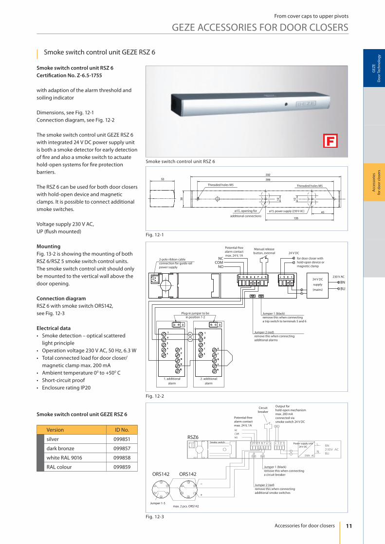
Smoke switch control unit GEZE RSZ 6
Smoke switch control unit RSZ 6
Certi� cation No. Z-6.5-1755
with adaption of the alarm threshold and
soiling indicator
Dimensions, see Fig. 12-1
Connection diagram, see Fig. 12-2
The smoke switch control unit GEZE RSZ 6
with integrated 24 V DC power supply unit
is both a smoke detector for early detection
of ! re and also a smoke switch to actuate
hold-open systems for ! re protection
barriers.
The RSZ 6 can be used for both door closers
with hold-open device and magnetic
clamps. It is possible to connect additional
smoke switches.
Voltage supply 230 V AC,
UP (" ush mounted)
Mounting
Fig. 13-2 is showing the mounting of both
RSZ 6/RSZ 5 smoke switch control units.
The smoke switch control unit should only
be mounted to the vertical wall above the
door opening.
Connection diagram
RSZ 6 with smoke switch ORS142,
see Fig. 12-3
Electrical data
• Smoke detection – optical scattered
light principle
• Operation voltage 230 V AC, 50 Hz, 6.3 W
• Total connected load for door closer/
magnetic clamp max. 200 mA
• Ambient temperature 00 to +500 C
• Short-circuit proof
• Enclosure rating IP20
Smoke switch control unit GEZE RSZ 6
Version ID No.
silver 099851
dark bronze 099857
white RAL 9016 099858
RAL colour 099859
Smoke switch control unit RSZ 6
Circuit
breaker
Potential-free
alarm contact
max. 24 V, 1A
Output for
hold-open mechanism
max. 200 mA
connected via
smoke switch 24 V DC
Jumper 1 (black)
remove this when connecting
a circuit breaker
Jumper 2 (red)
remove this when connecting
additional smoke switches
Jumper 1-5max. 2 pcs. ORS142
Power supply unit
24 V DC
Smoke switch
12
Fig. 13-1
Fig. 13-2
RS5 RS5
1
342
5
6
7
8
Fig. 13-3
Acc
ess
ori
es
for
do
or
clo
sers
GE
ZE
Do
or
Tech
no
log
y
GEZE DOOR TECHNOLOGY
From cover caps to upper pivots
GEZE ACCESSORIES FOR DOOR CLOSERS
Installation area „M“ as per illustration
LB = clear width LH = clear height
Connection clamp to E-guide rail
or TS 4000 E,
magnetic door
clamp, etc.
Cir
cuit
bre
ake
r
Mains
230 V
24 V DC
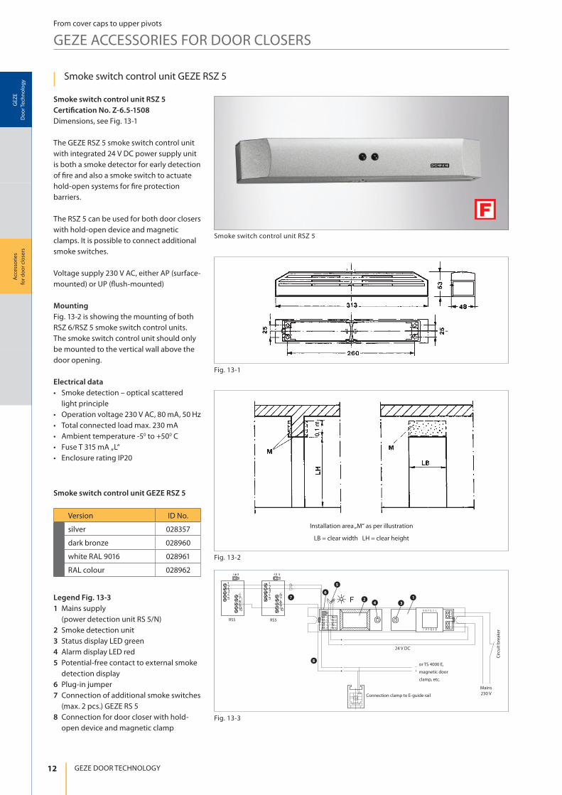
Smoke switch control unit GEZE RSZ 5
Smoke switch control unit RSZ 5
Certi� cation No. Z-6.5-1508
Dimensions, see Fig. 13-1
The GEZE RSZ 5 smoke switch control unit
with integrated 24 V DC power supply unit
is both a smoke detector for early detection
of ! re and also a smoke switch to actuate
hold-open systems for ! re protection
barriers.
The RSZ 5 can be used for both door closers
with hold-open device and magnetic
clamps. It is possible to connect additional
smoke switches.
Voltage supply 230 V AC, either AP (surface-
mounted) or UP (" ush-mounted)
Mounting
Fig. 13-2 is showing the mounting of both
RSZ 6/RSZ 5 smoke switch control units.
The smoke switch control unit should only
be mounted to the vertical wall above the
door opening.
Electrical data
• Smoke detection – optical scattered
light principle
• Operation voltage 230 V AC, 80 mA, 50 Hz
• Total connected load max. 230 mA
• Ambient temperature -50 to +500 C
• Fuse T 315 mA „L“
• Enclosure rating IP20
Legend Fig. 13-3
1 Mains supply
(power detection unit RS 5/N)
2 Smoke detection unit
3 Status display LED green
4 Alarm display LED red
5 Potential-free contact to external smoke
detection display
6 Plug-in jumper
7 Connection of additional smoke switches
(max. 2 pcs.) GEZE RS 5
8 Connection for door closer with hold-
open device and magnetic clamp
Smoke switch control unit GEZE RSZ 5
Version ID No.
silver 028357
dark bronze 028960
white RAL 9016 028961
RAL colour 028962
Smoke switch control unit RSZ 5

13
Fig. 14-1
RS5 RS5
42
5
6
7
8
Fig. 14-2
1
3
Fig. 14-3
Acc
ess
ori
es
for
do
or
clo
sers
GE
ZE
Do
or
Tech
no
log
y
Accessories for door closers
From cover caps to upper pivots
GEZE ACCESSORIES FOR DOOR CLOSERS
GEZE Smoke switch RS 5 and power supply unit RS 5/N
Smoke switch GEZE RS 5
Certi� cation No. Z-6.5-1508
Dimensions, see Fig. 14-1
The GEZE RS 5 smoke switch is a smoke
detector for the early detection of ! re.
When smoke is detected (optical scattered
light principle) the switch interrupts the power
supply for the door closer hold-open.
The RS 5 can be used for both door closers
with hold-open device and magnetic
clamps. Voltage supply 24 V DC, either AP
(surface-mounted) or UP (" ush-mounted)
Power supply unit GEZE RS 5/N
Certi� cation No. Z-6.5-1508
Dimensions, see Fig. 14-1
The GEZE RS 5/N is used to supply power to
the RS 5 smoke switch and door closer with
hold-open device or magnetic clamp.
Electrical data
• Power supply cable 2 x 1,5 mm2
230 V AC, 80 mA, 50 Hz
• Output voltage 24 V DC
• Output current max. 250 mA
• Ambient temperature -50 to +500 C
Connection diagram RS 5, see Fig. 14-2
2 Smoke detection unit
4 Alarm display LED red
5 Potential-free contact to external smoke
detection display
6 Plug-in jumper
7 Connection 1 additonal smoke switch RS 5
8 Connection for door closer with hold-
open device or magnetic clamp
Connection diagram RS 5/N, see Fig. 14-3
1 Mains supply
3 Status display LED green
Version RS 5 ID No.
silver 027052
dark bronze 028939
white RAL 9016 028940
RAL colour 028941
Version RS 5/N ID No.
silver 027053
dark bronze 028950
white RAL 9016 028951
RAL colour 028952
Connection clamp E-guide rail
or
TS 4000 E,
magnetic
clamp, etc.
Circuit breaker
Mains
230 V
24 V DC
24 V DC
Smoke switch RS 5 and power supply unit RS 5/N
14
16
3
14
0.4
Mat.Nr. 103403
78 61 56.9
Fig. 15-2
Fig. 15-1
6 665551 1 1
2 2 23 3 3
4 4 4
654321 K
FV FV
Fig. 15-3
Acc
ess
ori
es
for
do
or
clo
sers
GE
ZE
Do
or
Tech
no
log
y
GEZE DOOR TECHNOLOGY
From cover caps to upper pivots
GEZE ACCESSORIES FOR DOOR CLOSERS
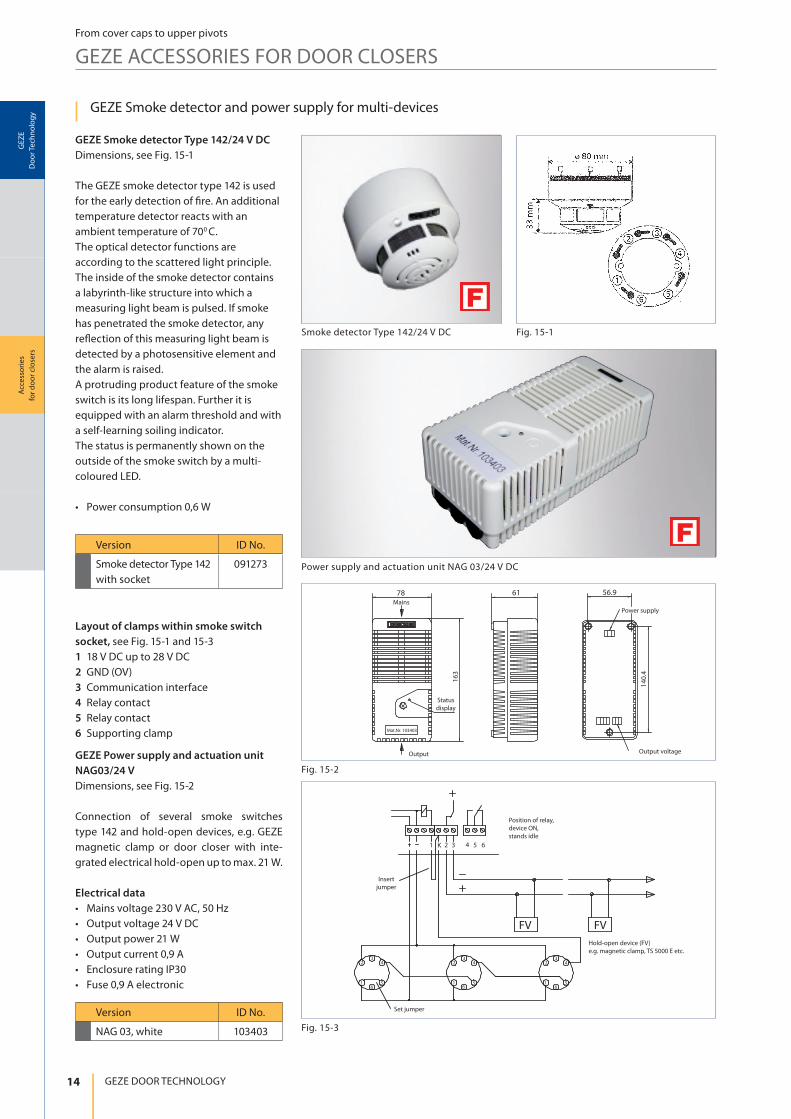
GEZE Smoke detector and power supply for multi-devices
GEZE Smoke detector Type 142/24 V DC
Dimensions, see Fig. 15-1
The GEZE smoke detector type 142 is used
for the early detection of ! re. An additional
temperature detector reacts with an
ambient temperature of 700 C.
The optical detector functions are
according to the scattered light principle.
The inside of the smoke detector contains
a labyrinth-like structure into which a
measuring light beam is pulsed. If smoke
has penetrated the smoke detector, any
re" ection of this measuring light beam is
detected by a photosensitive element and
the alarm is raised.
A protruding product feature of the smoke
switch is its long lifespan. Further it is
equipped with an alarm threshold and with
a self-learning soiling indicator.
The status is permanently shown on the
outside of the smoke switch by a multi-
coloured LED.
• Power consumption 0,6 W
Layout of clamps within smoke switch
socket, see Fig. 15-1 and 15-3
1 18 V DC up to 28 V DC
2 GND (OV)
3 Communication interface
4 Relay contact
5 Relay contact
6 Supporting clamp
Version ID No.
Smoke detector Type 142
with socket
091273
Version ID No.
NAG 03, white 103403
Smoke detector Type 142/24 V DC
Output voltage
Power supply
Status
display
Mains
Output
Insert
jumper
Set jumper
Position of relay,
device ON,
stands idle
Hold-open device (FV)
e.g. magnetic clamp, TS 5000 E etc.
Power supply and actuation unit NAG 03/24 V DC
GEZE Power supply and actuation unit
NAG03/24 V
Dimensions, see Fig. 15-2
Connection of several smoke switches
type 142 and hold-open devices, e.g. GEZE
magnetic clamp or door closer with inte-
grated electrical hold-open up to max. 21 W.
Electrical data
• Mains voltage 230 V AC, 50 Hz
• Output voltage 24 V DC
• Output power 21 W
• Output current 0,9 A
• Enclosure rating IP30
• Fuse 0,9 A electronic
15
Acc
ess
ori
es
for
do
or
clo
sers
GE
ZE
Do
or
Tech
no
log
y
Accessories for door closers
From cover caps to upper pivots
GEZE ACCESSORIES FOR DOOR CLOSERS
Circuit breaker
Magnetic clamp, length =335 mm Magnetic clamp, length =335 mm
Power
supply
24 V DC
Smoke detectorSmoke detector
Circuit breakerCircuit breaker
Magnetic clamp
Fire-proof door
Supply line 230 V
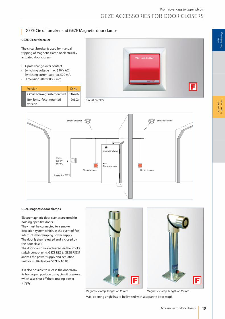
GEZE Circuit breaker and GEZE Magnetic door clamps
Version ID No.
Circuit breaker, ! ush-mounted 116266
Box for surface-mounted
version
120503
GEZE Circuit breaker
The circuit breaker is used for manual
tripping of magnetic clamp or electrically
actuated door closers.
• 1-pole change-over contact
• Switching voltage max. 250 V AC
• Switching current approx. 500 mA
• Dimensions 80 x 80 x 9 mm
GEZE Magnetic door clamps
Electromagnetic door clamps are used for
holding open " re doors.
They must be connected to a smoke
detection system which, in the event of " re,
interrupts the clamping power supply.
The door is then released and is closed by
the door closer.
The door clamps are actuated via the smoke
switch control units GEZE RSZ 6, GEZE RSZ 5
and via the power supply and actuation
unit for multi-devices GEZE NAG 03.
It is also possible to release the door from
its hold-open position using circuit breakers
which also shut o# the clamping power
supply.
Max. opening angle has to be limited with a separate door stop!
16
12
5
(27
5)
60
Fig. 17-1
90
75
ø 6,6
80
65
Fig. 17-2
18
5
4
(33
5)
Acc
ess
ori
es
for
do
or
clo
sers
GE
ZE
Do
or
Tech
no
log
y
GEZE DOOR TECHNOLOGY
From cover caps to upper pivots
GEZE ACCESSORIES FOR DOOR CLOSERS
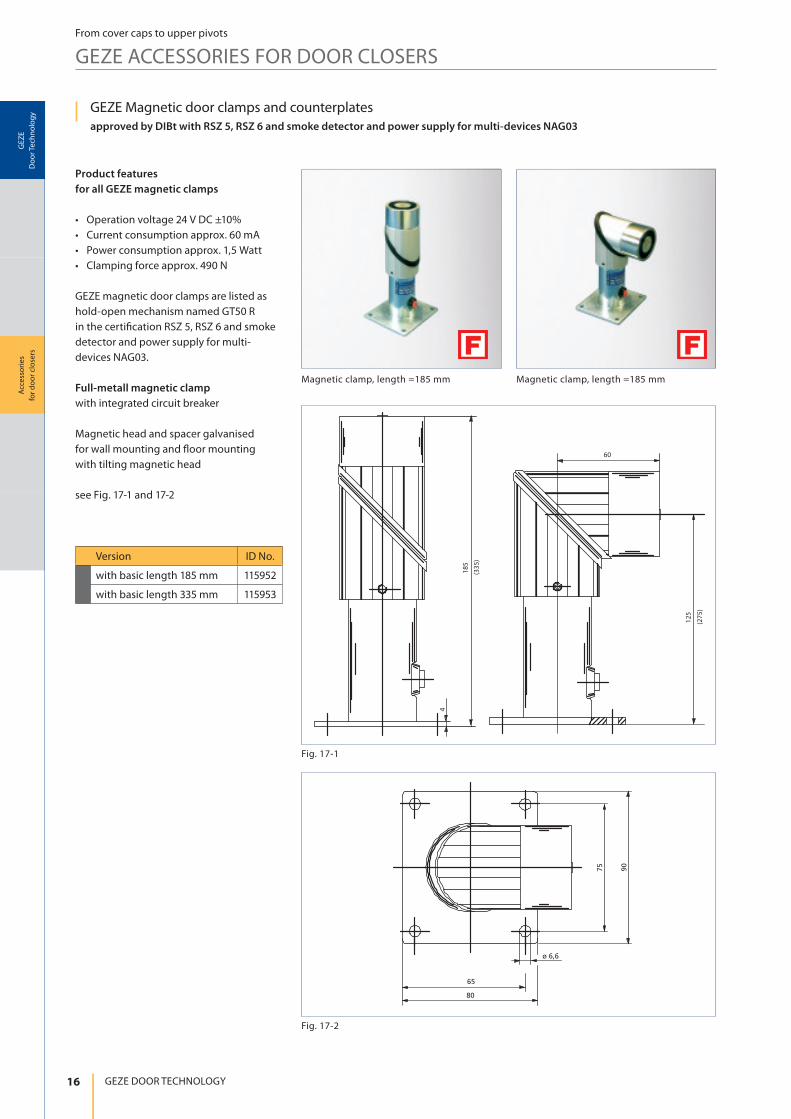
Magnetic clamp, length =185 mm Magnetic clamp, length =185 mm
GEZE Magnetic door clamps and counterplates
approved by DIBt with RSZ 5, RSZ 6 and smoke detector and power supply for multi-devices NAG03
Version ID No.
with basic length 185 mm 115952
with basic length 335 mm 115953
Product features
for all GEZE magnetic clamps
• Operation voltage 24 V DC ±10%
• Current consumption approx. 60 mA
• Power consumption approx. 1,5 Watt
• Clamping force approx. 490 N
GEZE magnetic door clamps are listed as
hold-open mechanism named GT50 R
in the certi" cation RSZ 5, RSZ 6 and smoke
detector and power supply for multi-
devices NAG03.
Full-metall magnetic clamp
with integrated circuit breaker
Magnetic head and spacer galvanised
for wall mounting and # oor mounting
with tilting magnetic head
see Fig. 17-1 and 17-2

17
ca. 93
85
6,5
102
ca. 120
50,5
15
4,5
85,5
109
10
ø 50
77
65
3
33
55
55
5
93
4,3
ø 34; 3 x 1200
M4
30
max. 8
4
ø 5
0
M8
Fig. 18-3
Fig. 18-2
Fig. 18-1
Acc
ess
ori
es
for
do
or
clo
sers
GE
ZE
Do
or
Tech
no
log
y
Accessories for door closers
From cover caps to upper pivots
GEZE ACCESSORIES FOR DOOR CLOSERS
Magnetic clamp, wall mounting Magnetic clamp, basic model Magnetic clamp, floor mounting
200 long
GEZE Magnetic door clamps and counterplates
Version ID No.
Magnetic clamp basic model 115830
Magnetic clam
wall mounting115829
Magnetic clamp
! oor mounting115951
GEZE Magnetic clamps
Magnetic clamp basic model
Magnetic head galvanised
(without base plate)
for wall mounting or installation in an
arbitrary construction, see Fig. 18-1
Magnetic clamp wall mounting
with base plate, see Fig. 18-2
Magnetic clamp ! oor mounting
with aluminium housing
and integrated circuit breaker, see Fig. 18-3
18
4,5
55
55
44
44
50
ø 5
5
0
79
ø 5
5
55
44
55
44
4,5
55
44
4,5
55
44
ø 5
5
18
Fig. 19-3
Fig. 19-2
Fig. 19-1
Acc
ess
ori
es
for
do
or
clo
sers
GE
ZE
Do
or
Tech
no
log
y
GEZE DOOR TECHNOLOGY
From cover caps to upper pivots
GEZE ACCESSORIES FOR DOOR CLOSERS
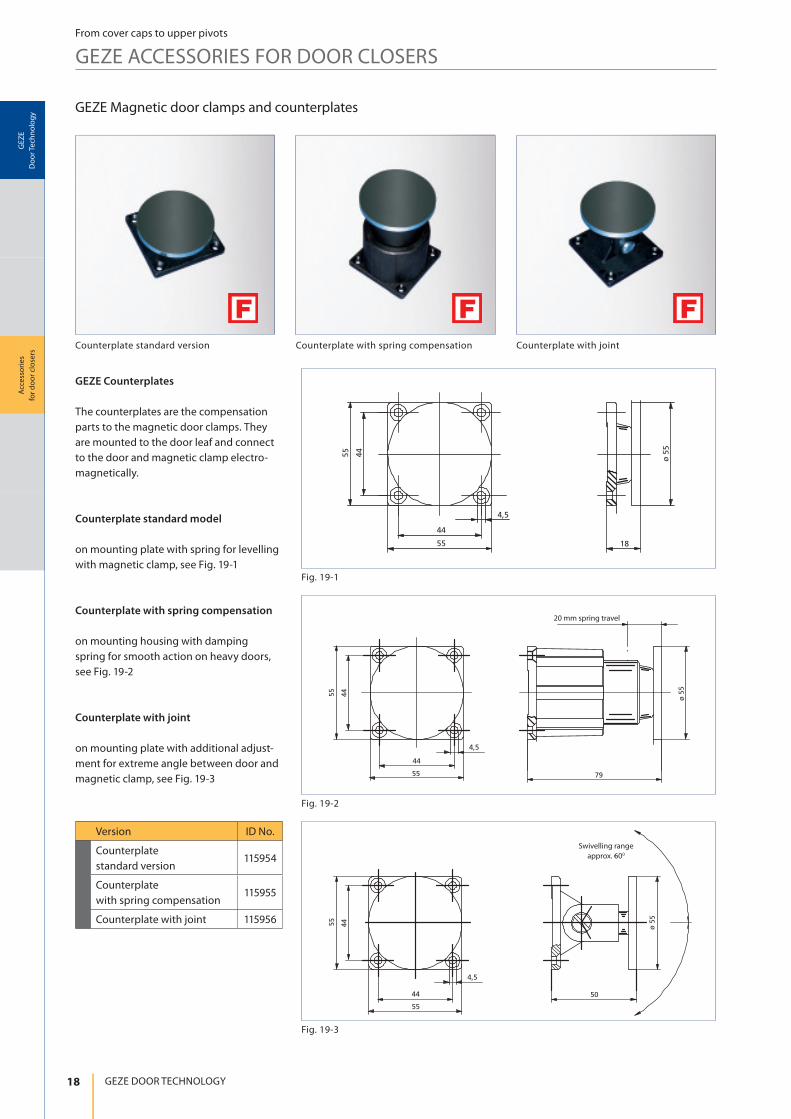
Counterplate with spring compensationCounterplate standard version Counterplate with joint
20 mm spring travel
Swivelling range
approx. 600
GEZE Magnetic door clamps and counterplates
Version ID No.
Counterplate
standard version115954
Counterplate
with spring compensation115955
Counterplate with joint 115956
GEZE Counterplates
The counterplates are the compensation
parts to the magnetic door clamps. They
are mounted to the door leaf and connect
to the door and magnetic clamp electro-
magnetically.
Counterplate standard model
on mounting plate with spring for levelling
with magnetic clamp, see Fig. 19-1
Counterplate with spring compensation
on mounting housing with damping
spring for smooth action on heavy doors,
see Fig. 19-2
Counterplate with joint
on mounting plate with additional adjust-
ment for extreme angle between door and
magnetic clamp, see Fig. 19-3
19
Acc
ess
ori
es
for
do
or
clo
sers
GE
ZE
Do
or
Tech
no
log
y
Accessories for door closers
From cover caps to upper pivots
GEZE ACCESSORIES FOR DOOR CLOSERS
References
Catholic church, Stuttgart
Rheinlandhaus, Köln

GEZE GmbH
P.O. Box 1363
71226 Leonberg
Germany
GEZE GmbH
Reinhold-Vöster-Straße 21-29
71229 Leonberg
Germany
Telefon +49 (0) 7152-203-0
Telefax +49 (0) 7152-203-310
www.geze.com
Germany
GEZE Sonderkonstruktionen GmbH
Planken 1
97944 Boxberg-Schweigern
Tel. +49 (0) 7930-92 94-0
Fax +49 (0) 7930-92 94-10
E-Mail: [email protected]
GEZE GmbH
Niederlassung Nord/Ost
Bühringstraße 8
13086 Berlin (Weissensee)
Tel. +49 (0) 30-47 89 90-0
Fax +49 (0) 30-47 89 90-17
E-Mail: [email protected]
GEZE GmbH
Niederlassung West
Nordsternstraße 65
45329 Essen
Tel. +49 (0) 201-83 082-0
Fax +49 (0) 201-83 082-20
E-Mail: [email protected]
GEZE GmbH
Niederlassung Mitte
Adenauerallee 2
61440 Oberursel (b. Frankfurt)
Tel. +49 (0) 6171-63 610-0
Fax +49 (0) 6171-63 610-1
E-Mail: [email protected]
GEZE GmbH
Niederlassung Süd
Breitwiesenstraße 8
71229 Leonberg
Tel. +49 (0) 7152-203-594
Fax +49 (0) 7152-203-438
E-Mail: [email protected]
GEZE Service GmbH NL Südwest
Reinhold-Vöster-Straße 25
71229 Leonberg
Tel. +49 (0) 7152-92 33 34
GEZE Service GmbH NL Nord-Ost
Bühringstraße 8
13086 Berlin (Weissensee)
Tel. +49 (0) 30-47 02 17 32
GEZE Service GmbH NL West
Nordsternstraße 65
45329 Essen
Tel. +49 (0) 201-8 30 82 16
GEZE Service GmbH NL Mitte
Feldbergstrasse 59
61440 Oberursel
Tel. +49 (0) 6171-63 327-0
GEZE Service GmbH NL Süd
Keltenring 10
85658 Egmating
Tel. +49 (0) 8095-87 13 61
Austria
GEZE Austria
Wiener Bundesstrasse 85
A-5300 Hallwang
Tel: +43/6225/87180
Fax: +43/6225/87180-299
E-Mail: [email protected]
Baltic States
GEZE GmbH Baltic States o! ce
Dzelzavas iela 120 S
1021 Riga
Tel. +371 (0) 67 89 60 35
Fax +371 (0) 67 89 60 36
E-Mail: o! [email protected]
Benelux
GEZE Benelux B.V.
Leemkuil 1
Industrieterrein Kapelbeemd
5626 EA Eindhoven
Tel. +31 (0) 40-26 290-80
Fax +31 (0) 40-26 290-85
E-Mail: [email protected]
Bulgaria
GEZE Bulgaria - Trade
Representative O! ce
61 Pirinski Prohod, entrance „B“,
4th " oor, o! ce 5,
1680 So# a
Tel. +359 (0) 24 70 43 73
Fax +359 (0) 24 70 62 62
E-Mail: o! [email protected]
India
GEZE India Private Ltd.
MF 2 & 3, Guindy Industrial Estate
Ekkattuthangal
Chennai 600 097
Tamilnadu
Tel. +91 (0) 44 30 61 69 00
Fax +91 (0) 44 30 61 69 01
E-Mail: o! [email protected]
Italy
GEZE Italia Srl
Via Giotto, 4
20040 Cambiago (MI)
Tel. +39 (0) 29 50 695-11
Fax +39 (0) 29 50 695-33
E-Mail: [email protected]
GEZE Engineering Roma Srl
Via Lucrezia Romana, 91
00178 Roma
Tel. +39 (0) 6-72 65 311
Fax +39 (0) 6-72 65 3136
E-Mail: [email protected]
Poland
GEZE Polska Sp.z o.o.
ul. Annopol 21
03-236 Warszawa
Tel. +48 (0) 22 440 4 440
Fax +48 (0) 22 440 4 400
E-Mail: [email protected]
Romania
GEZE Romania s.r.l.
IRIDE Business Park,
Str. Dimitrie Pompeiu nr. 9-9a,
Building 10, Level 2, Sector 2,
020335 Bucharest
Tel.: +40 (0) 21 25 07 750
Fax: +40 (0) 21 25 07 750
E-Mail: o! [email protected]
Russian Federation
GEZE GmbH Representative
O! ce Russia
Kolodesnij pereulok3, str. 25
O! ce Nr. 5201-5203
107076 Moskau
Tel. +7 (0) 49 55 89 90 52
Fax +7 (0) 49 55 89 90 51
E-Mail: o! [email protected]
Scandinavia – Sweden
GEZE Scandinavia AB
Mallslingan 10
Box 7060
18711 Täby, Sweden
Tel. +46 (0) 8-7323-400
Fax +46 (0) 8-7323-499
E-Mail: [email protected]
Scandinavia – Norway
GEZE Scandinavia AB avd. Norge
Industriveien 34 B
2073 Dal
Tel. +47 (0) 639-57 200
Fax +47 (0) 639-57 173
E-Mail: [email protected]
Scandinavia – Finland
Branch o! ce of GEZE Scandinavia AB
Herralantie 824
Postbox 20
15871 Hollola
Tel. +358 (0) 10-40 05 100
Fax +358 (0) 10-40 05 120
E-Mail: # [email protected]
Scandinavia – Denmark
GEZE Danmark
Branch o! ce of GEZE Scandinavia AB
Mårkærvej 13 J-K
2630 Taastrup
Tel. +45 (0) 46-32 33 24
Fax +45 (0) 46-32 33 26
E-Mail: [email protected]
South Africa
DCLSA Distributors (Pty.) Ltd.
118 Richards Drive, Halfway House,
Ext 111
P.O. Box 7934, Midrand 1685
Tel. +27 (0) 1131 58 286
Fax +27 (0) 1131 58 261
E-Mail: [email protected]
Switzerland
GEZE Schweiz AG
Bodenackerstrasse 79
4657 Dulliken
Tel. +41 (0) 62-285 54 00
Fax +41 (0) 62-285 54 01
E-Mail: [email protected]
Turkey
GEZE GmbH Türkiye - İstanbul
İrtibat Bürosu
Ataşehir Bulvarı, Ata 2/3
Plaza Kat: 9 D: 84 Ataşehir
Kadıköy / İstanbul
Tel. + 90 (0) 21 64 55 43 15
Fax + 90 (0) 21 64 55 82 15
E-Mail: o! [email protected]
Ukraine
GEZE Ukraine TOV
ul. Viskoznaya, 17,
Building 93-B, O! ce 12
02094 Kiev
Tel./Fax +38 (0) 44 501 22 25
Tel. +38 (0) 44 499 77 25
E-Mail: o! [email protected]
United Arab Emirates/GCC
GEZE Middle East
P.O. Box 17903
Jebel Ali Free Zone
Dubai
Tel. +971 (0) 4-88 33 112
Fax +971 (0) 4-88 33 240
E-Mail: [email protected]
United Kingdom
GEZE UK Ltd.
Blenheim Way
Fradley Park
Lich# eld
Sta; ordshire WS13 8SY
Tel. +44 (0) 1543 44 30 00
Fax +44 (0) 1543 44 30 01
E-Mail: [email protected]
China
GEZE Industries (Tianjin) Co., Ltd.
Shuangchenzhong Road
Beichen Economic Development
Area (BEDA)
Tianjin 300400, P.R. China
Tel. +86 (0) 22-26 97 39 95-0
Fax +86 (0) 22-26 97 27 02
E-Mail: [email protected]
GEZE Industries (Tianjin) Co., Ltd.
Branch O! ce Shanghai
Unit 25N, Cross Region Plaza
No 899, Ling Ling Road,
XuHui District
200030 Shanghai, P.R China
Tel. +86 (0) 21-523 40 960
Fax +86 (0) 21-644 72 007
E-Mail: [email protected]
GEZE Industries (Tianjin) Co., Ltd.
Branch O! ce Guangzhou
Room 17C3
Everbright Bank Building, No.689
Tian He Bei Road
510630 Guangzhou
P.R. China
Tel. +86 (0) 20-38 73 18 42
Fax +86 (0) 20-38 73 18 34
E-Mail: [email protected]
GEZE Industries (Tianjin) Co., Ltd
Branch O! ce Beijing
Room 1001, Tower D
Sanlitun SOHO
No. 8, Gongti North Road,
Chaoyang District
100027 Beijing, P.R.China
Tel. +86 (0) 10-59 35 93 00
Fax +86 (0)10-59 35 93 22
E-Mail: [email protected]
France
GEZE France S.A.R.L.
ZAC de l’Orme Rond
RN 19
77170 Servon
Tel. +33 (0) 1-60 62 60-70
Fax +33 (0) 1-60 62 60-71
E-Mail: [email protected]
Hungary
GEZE Hungary Kft.
Bartók Béla út 105-113.
Budapest
H-1115
Tel. +36 (1) 481 4670
Fax +36 (1) 481 4671
E-Mail: o! [email protected]
Iberia
GEZE Iberia S.R.L.
Pol. Ind. El Pla
C/Comerc, 2-22, Nave 12
08980 Sant Feliu de Llobregat
(Barcelona)
Tel. +34 9-02 19 40 36
Fax +34 9-02 19 40 35
E-Mail: [email protected]
G E Z E R E P R E S E N TAT I V E
G E Z E D O O R T E C H N O LO G Y
ID No. 091608 · Vers. EN 110713 · Subject to alterations