getting to know autocad - john wiley &...
TRANSCRIPT

CHAPTER 1
Getting to KnowAutoCAD� Opening a new drawing
� Getting familiar with the AutoCAD and AutoCAD LTGraphics windows
� Modifying the display
� Displaying and arranging toolbars
4414ch01.qxd 4/1/05 5:05 Page 1
COPYRIG
HTED M
ATERIAL
Your introduction to AutoCAD and AutoCAD LT begins with a tour of thefeatures of the screens used by the two programs. In this chapter, you willalso learn how to use some tools that help you control the screen’s appear-ance and how to find and start commands. For the material covered in this
chapter, the two applications are almost identical in appearance. Therefore, as wetour AutoCAD, I’ll point out any differences between AutoCAD and AutoCAD LT.In general, LT is a 2D program, so it doesn’t have the 3D features that come withAutoCAD, such as solids modeling and rendering. The other differences are minor.As mentioned in this book’s Introduction, when I say “AutoCAD,” I mean bothAutoCAD and AutoCAD LT. I’ll also refer to AutoCAD LT as “LT” throughout thischapter and the rest of the book. Starting up AutoCAD is the first task at hand.
Starting Up AutoCADIf you installed AutoCAD or LT using the default settings for the location of the pro-gram files, start AutoCAD by choosing Start ➣ All Programs ➣ Autodesk ➣ Auto-CAD 2006 ➣ AutoCAD 2006. For LT, choose Start ➣ All Programs ➣ Autodesk ➣
AutoCAD LT 2006 ➣ AutoCAD LT 2006. If you customized your installation, findand click the AutoCAD 2006 or the AutoCAD LT 2006 icon to start the program.
The Startup Dialog BoxIf AutoCAD or LT opens with the Startup dialog box sitting in front of the Auto-CAD Graphics window, your screen will look like Figure 1.1. If the Startup dialogbox doesn’t open, read on a little—you’ll see how to display it and then how tosuppress it.
The Startup dialog box has four buttons in the upper-left corner. The first twobuttons let you set up a new drawing and choose an existing drawing to revise orupdate. The second two buttons use templates and wizards to initiate advancedsetup routines. The contents of the middle portion of the dialog box depend onwhich of the four buttons you choose. By beginning a new drawing, you can getpast this dialog box to the AutoCAD Graphics window.
1. Click the Start From Scratch button, the second button from the left.
2. In the Default Settings section, click the Imperial (Feet And Inches)radio button.
3. Click OK to close the Startup dialog box. Your monitor displays theAutoCAD or LT Graphics window, sometimes called the GraphicalUser Interface, or GUI (see Figure 1.2).
C h a p t e r 1 • G e t t i n g t o K n o w A u t o C A D2
�
Dialog boxes withvarious combinationsof buttons and textboxes are used exten-sively in AutoCADand LT.You will learntheir many functionsas you progressthrough the book.
�
Radio buttons areround and come in alist or a group.Youcan activate only oneradio button at a time.
4414ch01.qxd 4/1/05 5:05 Page 2
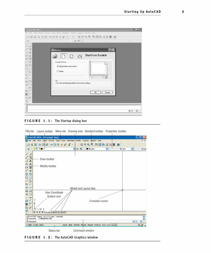
F I G U R E 1 . 1 : The Startup dialog box
F I G U R E 1 . 2 : The AutoCAD Graphics window
Title bar Menu bar Drawing area Standard toolbar Properties toolbar
Crosshair cursor
Model and Layout tabsUser Coordinate
System icon
Draw toolbar
Modify toolbar
Status bar Command window
Layers toolbar
S t a r t i n g U p A u t o C A D 3
4414ch01.qxd 4/1/05 5:05 Page 3
N O T E If the New Features Workshop window appears when you startup AutoCAD, click the second or third radio button in the window, and thenclick OK to remove it. You can always access it on the Help menu.
The toolbars on your screen may not be in exactly the same places as they areshown in Figure 1.2. I recommend that you set your screen to look like the onehere, as it will make following through the book that much easier. Later in thischapter, you will see how to move the toolbars, display new ones and place them,and delete them.
Another feature called palettes might be visible on the far-right side of yourscreen when you start AutoCAD. Palettes can display as a rectangular area or as avertical title bar. If they appear, choose Tools ➣ Tool Palettes Window to tem-porarily close the palettes. We’ll take a look at them in Chapters 7 and 9.
CONTROLL ING THE WAY AUTOCAD STARTS UP
You can set AutoCAD and LT to display or hide the Startup dialog box whenyou start AutoCAD.
1. From the menu bar, choose Tools ➣ Options to open the Options dia-log box.
2. Click the System tab to bring it forward.
3. In the General Options section, open the Startup drop-down list.
� If you want AutoCAD to display the Startup dialog box, click ShowStartup Dialog Box.
� If you want AutoCAD to start up with a blank drawing, click DoNot Show A Startup Dialog.
4. Click Apply, and then click OK.
The next time you start up AutoCAD, your preference will be used.
C h a p t e r 1 • G e t t i n g t o K n o w A u t o C A D4
4414ch01.qxd 4/1/05 5:05 Page 4
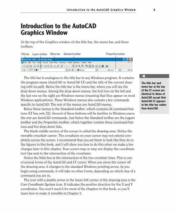
Introduction to the AutoCAD Graphics WindowAt the top of the Graphics window sit the title bar, the menu bar, and threetoolbars.
The title bar is analogous to the title bar in any Windows program. It containsthe program name (AutoCAD or AutoCAD LT) and the title of the current draw-ing with its path. Below the title bar is the menu bar, where you will see thedrop-down menus. Among the drop-down menus, the first two on the left andthe last one on the right are Windows menus (meaning that they appear on mostWindows applications). These Windows menus also contain a few commandsspecific to AutoCAD. The rest of the menus are AutoCAD menus.
Below these menus is the Standard toolbar, which contains 24 command but-tons (LT has only 22). Several of these buttons will be familiar to Windows users;the rest are AutoCAD commands. Just below the Standard toolbar are the Layerstoolbar and the Properties toolbar, which together contain three command but-tons and five drop-down lists.
The blank middle section of the screen is called the drawing area. Notice themovable crosshair cursor. The crosshairs on your cursor may not extend com-pletely across the screen. I recommend that you set them to look like they do inthe figures in this book, and I will show you how to do this when we make a fewchanges later in this chapter. Your screen may or may not display the coordinatetool tips next to the intersection of the crosshairs.
Notice the little box at the intersection of the two crosshair lines. This is oneof several forms of the AutoCAD and LT cursor. When you move the cursor offthe drawing area, it changes to the standard Windows pointing arrow. As youbegin using commands, it will take on other forms, depending on which step of acommand you are in.
The icon with a double arrow in the lower-left corner of the drawing area is theUser Coordinate System icon. It indicates the positive direction for the X and Ycoordinates. You won’t need it for most of the chapters in this book, so you’lllearn how to make it invisible in Chapter 3.
Title bar Menu bar Standard toolbar Properties toolbarLayers toolbar
I n t r o d u c t i o n t o t h e A u t o C A D G r a p h i c s Wi n d o w 5
�
The title bar andmenu bar at the topof the LT screen areidentical to those ofAutoCAD except thatAutoCAD LT appearsin the title bar ratherthan AutoCAD.
4414ch01.qxd 4/1/05 5:05 Page 5
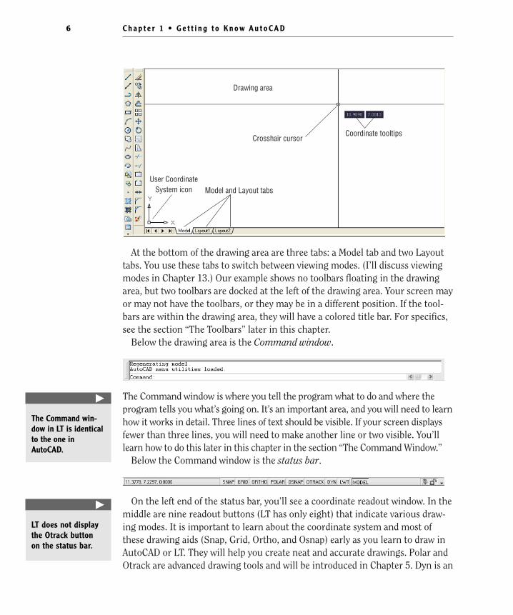
At the bottom of the drawing area are three tabs: a Model tab and two Layouttabs. You use these tabs to switch between viewing modes. (I’ll discuss viewingmodes in Chapter 13.) Our example shows no toolbars floating in the drawingarea, but two toolbars are docked at the left of the drawing area. Your screen mayor may not have the toolbars, or they may be in a different position. If the tool-bars are within the drawing area, they will have a colored title bar. For specifics,see the section “The Toolbars” later in this chapter.
Below the drawing area is the Command window.
The Command window is where you tell the program what to do and where theprogram tells you what’s going on. It’s an important area, and you will need to learnhow it works in detail. Three lines of text should be visible. If your screen displaysfewer than three lines, you will need to make another line or two visible. You’lllearn how to do this later in this chapter in the section “The Command Window.”
Below the Command window is the status bar.
On the left end of the status bar, you’ll see a coordinate readout window. In themiddle are nine readout buttons (LT has only eight) that indicate various draw-ing modes. It is important to learn about the coordinate system and most ofthese drawing aids (Snap, Grid, Ortho, and Osnap) early as you learn to draw inAutoCAD or LT. They will help you create neat and accurate drawings. Polar andOtrack are advanced drawing tools and will be introduced in Chapter 5. Dyn is an
Coordinate tooltips
Drawing area
Crosshair cursor
User CoordinateSystem icon Model and Layout tabs
C h a p t e r 1 • G e t t i n g t o K n o w A u t o C A D6
�
The Command win-dow in LT is identicalto the one inAutoCAD.
�
LT does not displaythe Otrack button on the status bar.
4414ch01.qxd 4/1/05 5:05 Page 6
OFF/ON toggle that activates or suppresses the dynamic display of informationnext to the crosshair cursor when it’s in the drawing area. For now, keep it in theOFF, or unpushed, mode. Lwt stands for Lineweight and will be discussed inChapter 14 in the section on plotting. The Model button is an advanced aid thatwill be covered in Chapter 13. At the far right of the status bar are small iconsthat indicate the presence of various features for a drawing session. The SatelliteDish button activates AutoCAD’s Communication Center and is discussed in abonus chapter available on Sybex’s website (www.sybex.com). The Padlock iconcontrols which types of toolbars and windows are locked in their current posi-tions on the screen. Leave it in the unlocked mode for now.
This has been a quick introduction to the various parts of the Graphics win-dow. I didn’t mention a couple of items that might be visible on your screen. Youmight have scroll bars below and to the right of the drawing area, and you mighthave a menu on the right side of the drawing area. Both features can be useful,but they can also be a hindrance and can take up precious space in the drawingarea. They won’t be of any use while working your way through this book, so Isuggest that you remove them for now.
To temporarily remove these features, follow these steps:
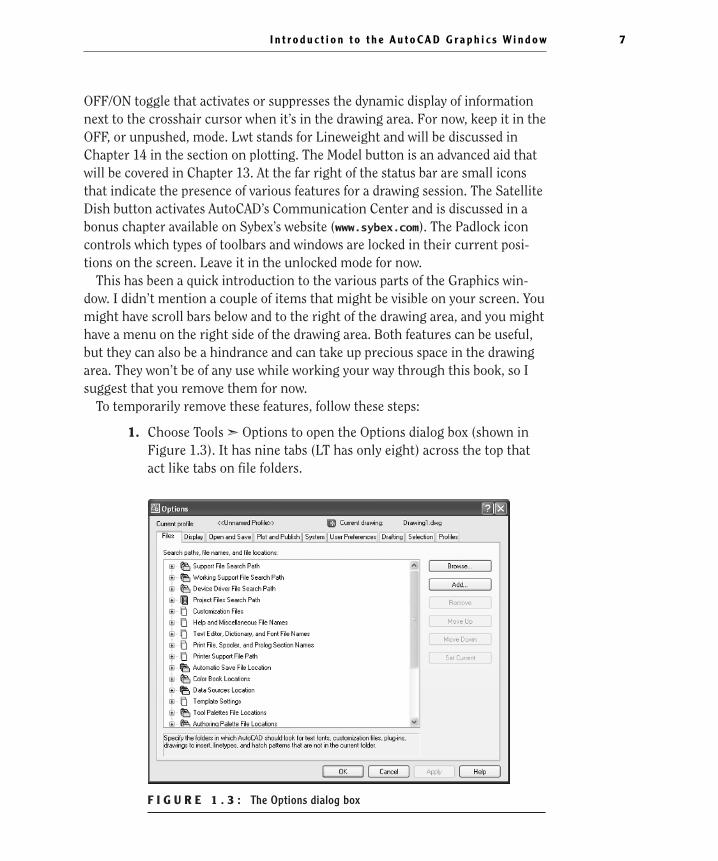
1. Choose Tools ➣ Options to open the Options dialog box (shown inFigure 1.3). It has nine tabs (LT has only eight) across the top thatact like tabs on file folders.
F I G U R E 1 . 3 : The Options dialog box
I n t r o d u c t i o n t o t h e A u t o C A D G r a p h i c s Wi n d o w 7
4414ch01.qxd 4/1/05 5:05 Page 7
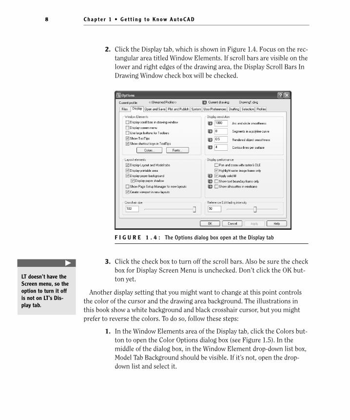
2. Click the Display tab, which is shown in Figure 1.4. Focus on the rec-tangular area titled Window Elements. If scroll bars are visible on thelower and right edges of the drawing area, the Display Scroll Bars InDrawing Window check box will be checked.
F I G U R E 1 . 4 : The Options dialog box open at the Display tab
3. Click the check box to turn off the scroll bars. Also be sure the checkbox for Display Screen Menu is unchecked. Don’t click the OK but-ton yet.
Another display setting that you might want to change at this point controlsthe color of the cursor and the drawing area background. The illustrations inthis book show a white background and black crosshair cursor, but you mightprefer to reverse the colors. To do so, follow these steps:
1. In the Window Elements area of the Display tab, click the Colors but-ton to open the Color Options dialog box (see Figure 1.5). In themiddle of the dialog box, in the Window Element drop-down list box,Model Tab Background should be visible. If it’s not, open the drop-down list and select it.
C h a p t e r 1 • G e t t i n g t o K n o w A u t o C A D8
�
LT doesn’t have theScreen menu, so theoption to turn it offis not on LT’s Dis-play tab.
4414ch01.qxd 4/1/05 5:05 Page 8
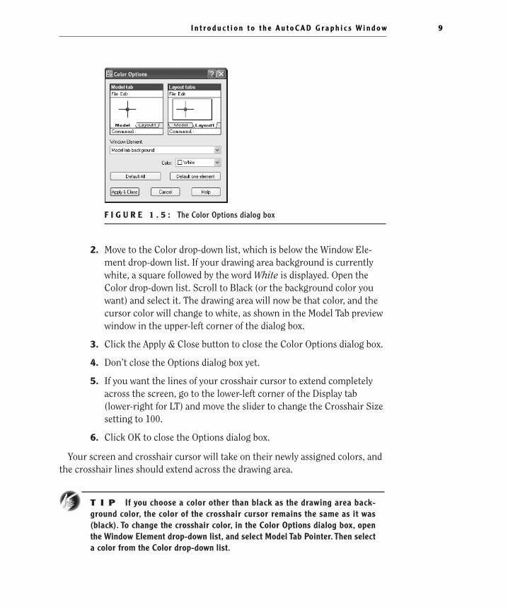
F I G U R E 1 . 5 : The Color Options dialog box
2. Move to the Color drop-down list, which is below the Window Ele-ment drop-down list. If your drawing area background is currentlywhite, a square followed by the word White is displayed. Open theColor drop-down list. Scroll to Black (or the background color youwant) and select it. The drawing area will now be that color, and thecursor color will change to white, as shown in the Model Tab previewwindow in the upper-left corner of the dialog box.
3. Click the Apply & Close button to close the Color Options dialog box.
4. Don’t close the Options dialog box yet.
5. If you want the lines of your crosshair cursor to extend completelyacross the screen, go to the lower-left corner of the Display tab(lower-right for LT) and move the slider to change the Crosshair Sizesetting to 100.
6. Click OK to close the Options dialog box.
Your screen and crosshair cursor will take on their newly assigned colors, andthe crosshair lines should extend across the drawing area.
T I P If you choose a color other than black as the drawing area back-ground color, the color of the crosshair cursor remains the same as it was(black). To change the crosshair color, in the Color Options dialog box, openthe Window Element drop-down list, and select Model Tab Pointer. Then selecta color from the Color drop-down list.
I n t r o d u c t i o n t o t h e A u t o C A D G r a p h i c s Wi n d o w 9
4414ch01.qxd 4/1/05 5:05 Page 9
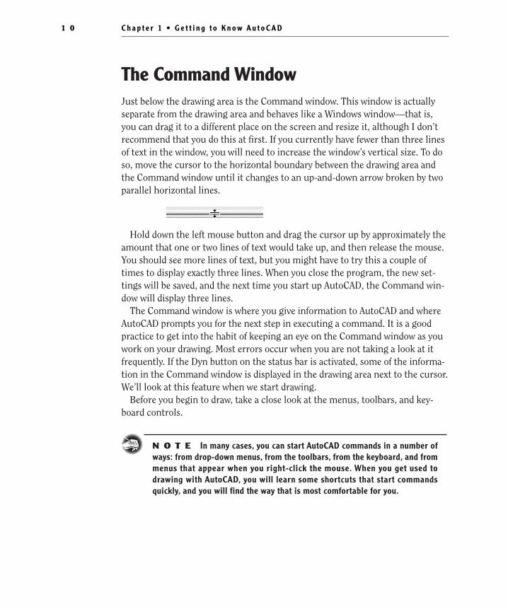
The Command WindowJust below the drawing area is the Command window. This window is actuallyseparate from the drawing area and behaves like a Windows window—that is,you can drag it to a different place on the screen and resize it, although I don’trecommend that you do this at first. If you currently have fewer than three linesof text in the window, you will need to increase the window’s vertical size. To doso, move the cursor to the horizontal boundary between the drawing area andthe Command window until it changes to an up-and-down arrow broken by twoparallel horizontal lines.
Hold down the left mouse button and drag the cursor up by approximately theamount that one or two lines of text would take up, and then release the mouse.You should see more lines of text, but you might have to try this a couple oftimes to display exactly three lines. When you close the program, the new set-tings will be saved, and the next time you start up AutoCAD, the Command win-dow will display three lines.
The Command window is where you give information to AutoCAD and whereAutoCAD prompts you for the next step in executing a command. It is a goodpractice to get into the habit of keeping an eye on the Command window as youwork on your drawing. Most errors occur when you are not taking a look at itfrequently. If the Dyn button on the status bar is activated, some of the informa-tion in the Command window is displayed in the drawing area next to the cursor.We’ll look at this feature when we start drawing.
Before you begin to draw, take a close look at the menus, toolbars, and key-board controls.
N O T E In many cases, you can start AutoCAD commands in a number ofways: from drop-down menus, from the toolbars, from the keyboard, and frommenus that appear when you right-click the mouse. When you get used todrawing with AutoCAD, you will learn some shortcuts that start commandsquickly, and you will find the way that is most comfortable for you.
C h a p t e r 1 • G e t t i n g t o K n o w A u t o C A D1 0
4414ch01.qxd 4/1/05 5:05 Page 10
Drop-Down MenusThe menu bar, just below the title bar (see Figure 1.2 earlier in this chapter), con-sists of 11 (12 if you have the Express tools installed) words and an icon. Click anyof these to display a drop-down menu. The icon on the left end and the File and Editmenus are included with all Windows-compatible applications, although they aresomewhat customized to work with AutoCAD. The menu associated with the iconcontains commands to control the appearance and position of the drawing area.
Commands in the File menu are for opening and saving new and existingdrawing files, printing, linking on the Internet, exporting files to another appli-cation, choosing basic utility options, and exiting the application. The Edit menucontains the Undo and Redo commands, the Cut and Paste tools, and options forcreating links between AutoCAD files and other files. The Help menu (the lastmenu on the right) works like all Windows Help menus and contains a couple ofAutoCAD-specific entries as well, including some online resources and a context-sensitive help feature called the Info Palette.
The other eight or nine menus contain the most-often-used AutoCAD com-mands. You will find that if you master the logic of how the commands are orga-nized by menu, you can quickly find the command you want. Here is a shortdescription of each of the other AutoCAD drop-down menus:
View Contains tools for controlling the display of your drawing file.
Insert Contains commands for placing drawings and images or parts of theminside other drawings.
Format Contains commands for setting up the general parameters for a newdrawing.
Tools Contains special tools for use while you are working on the current draw-ing, such as those for finding the length of a line or for running a special macro.
Draw Contains commands for creating new objects (such as lines or circles) onthe screen.
Dimension Contains commands for dimensioning a drawing.
Modify Contains commands for changing existing objects in the drawing.
Express This is an optional menu containing a library of productivity toolsthat cover a wide range of AutoCAD functions. It may or may not be installed onyour computer.
Window Contains commands for displaying currently open windows and listscurrently open drawing files.
D r o p - D o w n M e n u s 1 1
4414ch01.qxd 4/1/05 5:05 Page 11
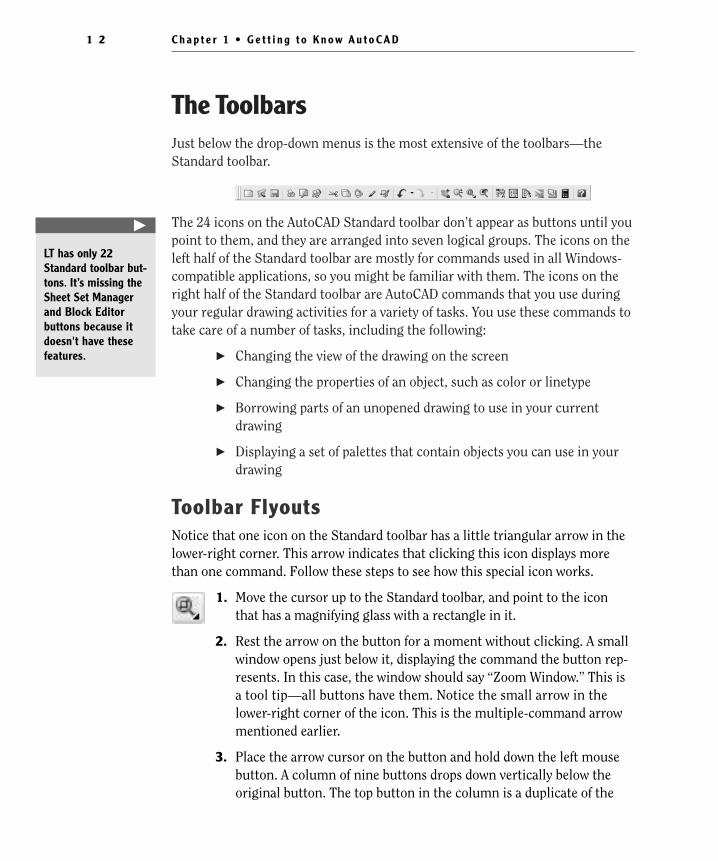
The ToolbarsJust below the drop-down menus is the most extensive of the toolbars—theStandard toolbar.
The 24 icons on the AutoCAD Standard toolbar don’t appear as buttons until youpoint to them, and they are arranged into seven logical groups. The icons on theleft half of the Standard toolbar are mostly for commands used in all Windows-compatible applications, so you might be familiar with them. The icons on theright half of the Standard toolbar are AutoCAD commands that you use duringyour regular drawing activities for a variety of tasks. You use these commands totake care of a number of tasks, including the following:
� Changing the view of the drawing on the screen
� Changing the properties of an object, such as color or linetype
� Borrowing parts of an unopened drawing to use in your currentdrawing
� Displaying a set of palettes that contain objects you can use in yourdrawing
Toolbar FlyoutsNotice that one icon on the Standard toolbar has a little triangular arrow in thelower-right corner. This arrow indicates that clicking this icon displays morethan one command. Follow these steps to see how this special icon works.
1. Move the cursor up to the Standard toolbar, and point to the iconthat has a magnifying glass with a rectangle in it.
2. Rest the arrow on the button for a moment without clicking. A smallwindow opens just below it, displaying the command the button rep-resents. In this case, the window should say “Zoom Window.” This isa tool tip—all buttons have them. Notice the small arrow in thelower-right corner of the icon. This is the multiple-command arrowmentioned earlier.
3. Place the arrow cursor on the button and hold down the left mousebutton. A column of nine buttons drops down vertically below theoriginal button. The top button in the column is a duplicate of the
C h a p t e r 1 • G e t t i n g t o K n o w A u t o C A D1 2
�
LT has only 22Standard toolbar but-tons. It’s missing theSheet Set Managerand Block Editorbuttons because itdoesn't have thesefeatures.
4414ch01.qxd 4/1/05 5:05 Page 12
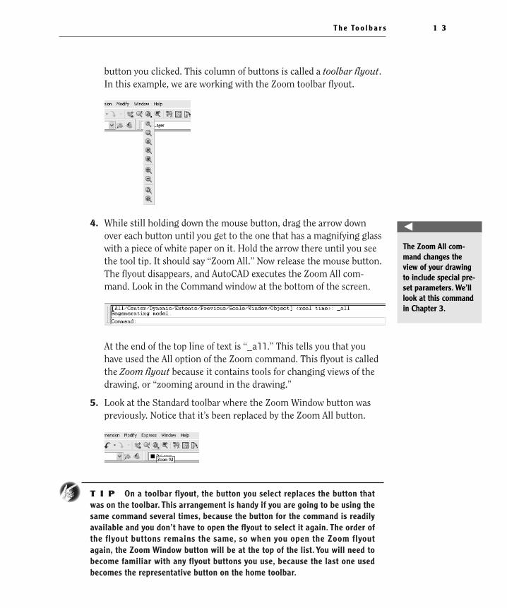
button you clicked. This column of buttons is called a toolbar flyout.In this example, we are working with the Zoom toolbar flyout.
4. While still holding down the mouse button, drag the arrow downover each button until you get to the one that has a magnifying glasswith a piece of white paper on it. Hold the arrow there until you seethe tool tip. It should say “Zoom All.” Now release the mouse button.The flyout disappears, and AutoCAD executes the Zoom All com-mand. Look in the Command window at the bottom of the screen.
At the end of the top line of text is “_all.” This tells you that youhave used the All option of the Zoom command. This flyout is calledthe Zoom flyout because it contains tools for changing views of thedrawing, or “zooming around in the drawing.”
5. Look at the Standard toolbar where the Zoom Window button waspreviously. Notice that it’s been replaced by the Zoom All button.
T I P On a toolbar flyout, the button you select replaces the button thatwas on the toolbar. This arrangement is handy if you are going to be using thesame command several times, because the button for the command is readilyavailable and you don’t have to open the flyout to select it again. The order ofthe flyout buttons remains the same, so when you open the Zoom flyoutagain, the Zoom Window button will be at the top of the list. You will need tobecome familiar with any flyout buttons you use, because the last one usedbecomes the representative button on the home toolbar.
T h e To o l b a r s 1 3
�
The Zoom All com-mand changes theview of your drawingto include special pre-set parameters. We’lllook at this commandin Chapter 3.
4414ch01.qxd 4/1/05 5:05 Page 13
The behavior of the Zoom flyout on the Standard toolbar is the same as thebehavior of flyouts in general.
N O T E Whenever you start up AutoCAD or LT for a new drawing session,the toolbars are reset and contain the original flyout buttons.
The toolbar flyouts are actually regular toolbars that have been attached toanother toolbar. There are 30 toolbars in all, and only 2 are flyouts—the Zoomflyout I just discussed, and the Insert flyout on the Draw toolbar. You can displaythe Zoom and Insert flyouts as regular toolbars, independent of the Standardand Draw toolbars.
Displaying and Arranging ToolbarsIn this section, I’ll use the Zoom toolbar to show you some ways you can controland manipulate toolbars. Follow these steps:
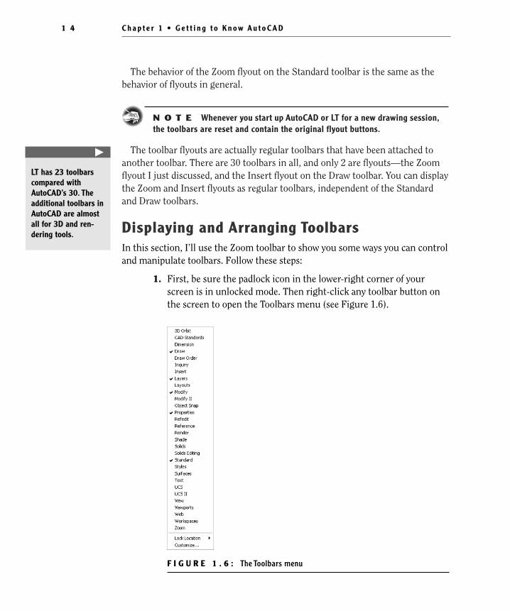
1. First, be sure the padlock icon in the lower-right corner of yourscreen is in unlocked mode. Then right-click any toolbar button onthe screen to open the Toolbars menu (see Figure 1.6).
F I G U R E 1 . 6 : The Toolbars menu
C h a p t e r 1 • G e t t i n g t o K n o w A u t o C A D1 4
�
LT has 23 toolbarscompared withAutoCAD’s 30. Theadditional toolbars inAutoCAD are almostall for 3D and ren-dering tools.
4414ch01.qxd 4/1/05 5:05 Page 14
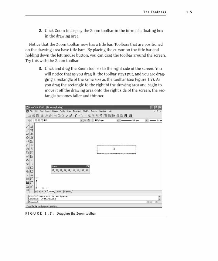
2. Click Zoom to display the Zoom toolbar in the form of a floating boxin the drawing area.
Notice that the Zoom toolbar now has a title bar. Toolbars that are positionedon the drawing area have title bars. By placing the cursor on the title bar andholding down the left mouse button, you can drag the toolbar around the screen.Try this with the Zoom toolbar.
3. Click and drag the Zoom toolbar to the right side of the screen. Youwill notice that as you drag it, the toolbar stays put, and you are drag-ging a rectangle of the same size as the toolbar (see Figure 1.7). Asyou drag the rectangle to the right of the drawing area and begin tomove it off the drawing area onto the right side of the screen, the rec-tangle becomes taller and thinner.
F I G U R E 1 . 7 : Dragging the Zoom toolbar
T h e To o l b a r s 1 5
4414ch01.qxd 4/1/05 5:05 Page 15
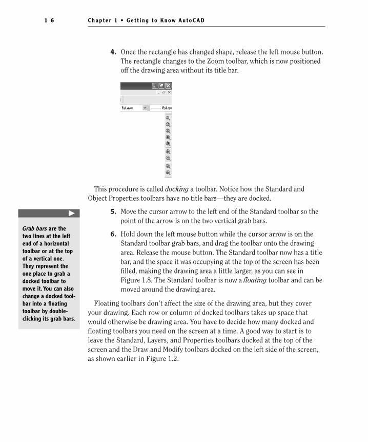
4. Once the rectangle has changed shape, release the left mouse button.The rectangle changes to the Zoom toolbar, which is now positionedoff the drawing area without its title bar.
This procedure is called docking a toolbar. Notice how the Standard andObject Properties toolbars have no title bars—they are docked.
5. Move the cursor arrow to the left end of the Standard toolbar so thepoint of the arrow is on the two vertical grab bars.
6. Hold down the left mouse button while the cursor arrow is on theStandard toolbar grab bars, and drag the toolbar onto the drawingarea. Release the mouse button. The Standard toolbar now has a titlebar, and the space it was occupying at the top of the screen has beenfilled, making the drawing area a little larger, as you can see inFigure 1.8. The Standard toolbar is now a floating toolbar and can bemoved around the drawing area.
Floating toolbars don’t affect the size of the drawing area, but they coveryour drawing. Each row or column of docked toolbars takes up space thatwould otherwise be drawing area. You have to decide how many docked andfloating toolbars you need on the screen at a time. A good way to start is toleave the Standard, Layers, and Properties toolbars docked at the top of thescreen and the Draw and Modify toolbars docked on the left side of the screen,as shown earlier in Figure 1.2.
C h a p t e r 1 • G e t t i n g t o K n o w A u t o C A D1 6
�
Grab bars are thetwo lines at the leftend of a horizontaltoolbar or at the topof a vertical one.They represent theone place to grab adocked toolbar tomove it. You can alsochange a docked tool-bar into a floatingtoolbar by double-clicking its grab bars.
4414ch01.qxd 4/1/05 5:05 Page 16
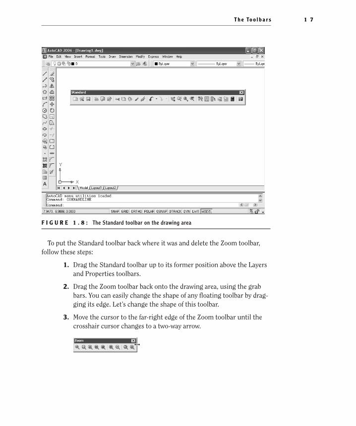
F I G U R E 1 . 8 : The Standard toolbar on the drawing area
To put the Standard toolbar back where it was and delete the Zoom toolbar,follow these steps:
1. Drag the Standard toolbar up to its former position above the Layersand Properties toolbars.
2. Drag the Zoom toolbar back onto the drawing area, using the grabbars. You can easily change the shape of any floating toolbar by drag-ging its edge. Let’s change the shape of this toolbar.
3. Move the cursor to the far-right edge of the Zoom toolbar until thecrosshair cursor changes to a two-way arrow.
T h e To o l b a r s 1 7
4414ch01.qxd 4/1/05 5:05 Page 17
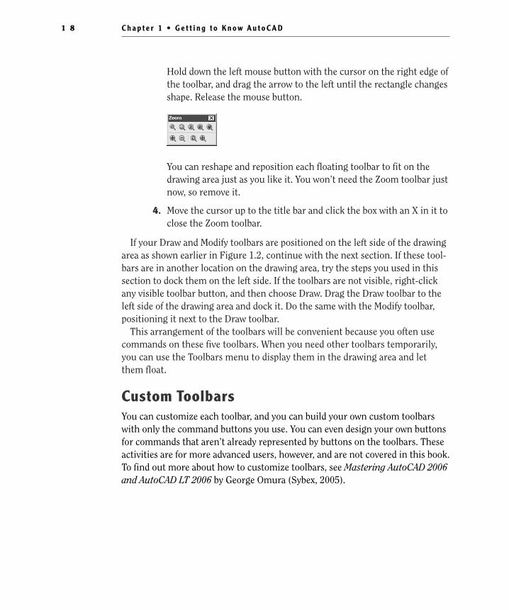
Hold down the left mouse button with the cursor on the right edge ofthe toolbar, and drag the arrow to the left until the rectangle changesshape. Release the mouse button.
You can reshape and reposition each floating toolbar to fit on thedrawing area just as you like it. You won’t need the Zoom toolbar justnow, so remove it.
4. Move the cursor up to the title bar and click the box with an X in it toclose the Zoom toolbar.
If your Draw and Modify toolbars are positioned on the left side of the drawingarea as shown earlier in Figure 1.2, continue with the next section. If these tool-bars are in another location on the drawing area, try the steps you used in thissection to dock them on the left side. If the toolbars are not visible, right-clickany visible toolbar button, and then choose Draw. Drag the Draw toolbar to theleft side of the drawing area and dock it. Do the same with the Modify toolbar,positioning it next to the Draw toolbar.
This arrangement of the toolbars will be convenient because you often usecommands on these five toolbars. When you need other toolbars temporarily,you can use the Toolbars menu to display them in the drawing area and letthem float.
Custom ToolbarsYou can customize each toolbar, and you can build your own custom toolbarswith only the command buttons you use. You can even design your own buttonsfor commands that aren’t already represented by buttons on the toolbars. Theseactivities are for more advanced users, however, and are not covered in this book.To find out more about how to customize toolbars, see Mastering AutoCAD 2006and AutoCAD LT 2006 by George Omura (Sybex, 2005).
C h a p t e r 1 • G e t t i n g t o K n o w A u t o C A D1 8
4414ch01.qxd 4/1/05 5:05 Page 18
ProfilesAs you become accustomed to working with AutoCAD, you will developyour own preferences for the layout of the AutoCAD Graphics window,
including:
� Which toolbars are docked and where
� The shape of the crosshair cursor
� The background color of the drawing area
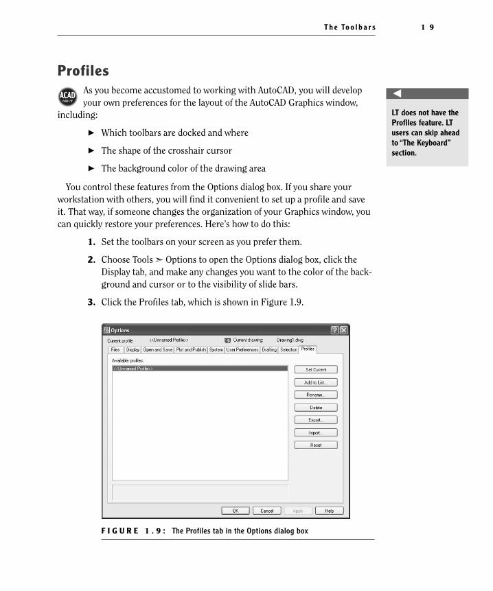
You control these features from the Options dialog box. If you share yourworkstation with others, you will find it convenient to set up a profile and saveit. That way, if someone changes the organization of your Graphics window, youcan quickly restore your preferences. Here’s how to do this:
1. Set the toolbars on your screen as you prefer them.
2. Choose Tools ➣ Options to open the Options dialog box, click theDisplay tab, and make any changes you want to the color of the back-ground and cursor or to the visibility of slide bars.
3. Click the Profiles tab, which is shown in Figure 1.9.
F I G U R E 1 . 9 : The Profiles tab in the Options dialog box
T h e To o l b a r s 1 9
�
LT does not have theProfiles feature. LTusers can skip aheadto “The Keyboard”section.
4414ch01.qxd 4/1/05 5:05 Page 19
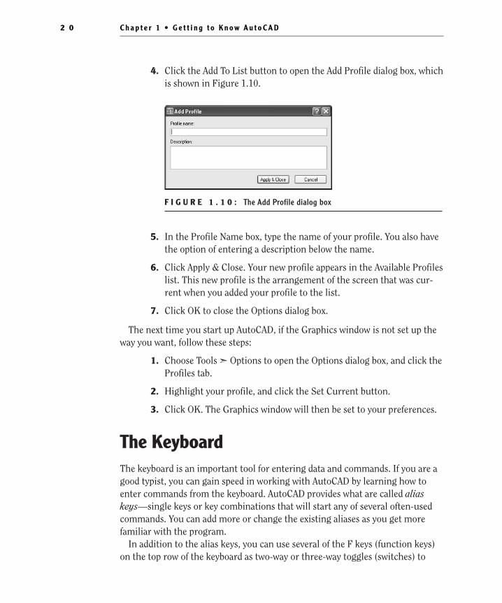
4. Click the Add To List button to open the Add Profile dialog box, whichis shown in Figure 1.10.
F I G U R E 1 . 1 0 : The Add Profile dialog box
5. In the Profile Name box, type the name of your profile. You also havethe option of entering a description below the name.
6. Click Apply & Close. Your new profile appears in the Available Profileslist. This new profile is the arrangement of the screen that was cur-rent when you added your profile to the list.
7. Click OK to close the Options dialog box.
The next time you start up AutoCAD, if the Graphics window is not set up theway you want, follow these steps:
1. Choose Tools ➣ Options to open the Options dialog box, and click theProfiles tab.
2. Highlight your profile, and click the Set Current button.
3. Click OK. The Graphics window will then be set to your preferences.
The KeyboardThe keyboard is an important tool for entering data and commands. If you are agood typist, you can gain speed in working with AutoCAD by learning how toenter commands from the keyboard. AutoCAD provides what are called aliaskeys—single keys or key combinations that will start any of several often-usedcommands. You can add more or change the existing aliases as you get morefamiliar with the program.
In addition to the alias keys, you can use several of the F keys (function keys)on the top row of the keyboard as two-way or three-way toggles (switches) to
C h a p t e r 1 • G e t t i n g t o K n o w A u t o C A D2 0
4414ch01.qxd 4/1/05 5:05 Page 20
turn AutoCAD functions on and off. Although buttons on the screen duplicatethese functions (Snap, Grid, and so on), it is sometimes faster to use the F keys.
Finally, you can activate commands on the drop-down menus from the key-board, rather than using the mouse. If you press the Alt key, an underlined letter,called a hotkey, appears on each menu. Pressing the key for the underlined letteractivates the menu. Each command on the menu also has a hotkey. Once youactivate the menu with the hotkey combination, you can type the underlined let-ter of these commands. For a few commands, this method can be the fastest wayto start them up and to select options.
While working in AutoCAD, you will need to key in a lot of data, such asdimensions and construction notes, answer questions with “yes” or “no,” anduse the arrow keys. You will use the keyboard constantly. It may help to getinto the habit of keeping the left hand on the keyboard and the right hand onthe mouse—if you are right-handed—or the other way around, if you are left-handed.
The MouseYour mouse will most likely have two or three buttons. (If it’s an IntelliMouse, itwill have two or more buttons with a wheel between them.) So far in this chap-ter, you have used the left mouse button for choosing menus, commands, orcommand options or for holding down the button and dragging a menu, toolbar,or window. The left mouse button is the one you will be using most often, butyou will also use the right mouse button.
While drawing, you will use the right mouse button for the following threeoperations:
� To display a menu containing options relevant to the particular stepyou are in at the moment
� To use in combination with the Shift or Control key to display amenu containing special drawing aids called Object Snaps (see Chap-ter 10)
� To display a menu of toolbars when the pointer is on any icon of atoolbar that is currently open
If you have a three-button mouse, the middle button is usually programmed todisplay the Object Snap menu, instead of using the right button with the Shiftkey. If you have an IntelliMouse, you can use the wheel in several ways to controlthe view of your drawing. I’ll cover those methods in subsequent chapters.
T h e M o u s e 2 1
4414ch01.qxd 4/1/05 5:05 Page 21
AutoCAD makes extensive use of toolbars and the right-click menu feature.This makes your mouse an important input tool. The keyboard is necessary forinputting numeric data and text, and it has hotkeys and aliases that can speed upyour work. But the mouse is the primary tool for starting commands, selectingoptions, and controlling toolbars.
The next chapter will familiarize you with a few basic commands that willenable you to draw a small diagram. If you are going to take a break and want toclose AutoCAD, choose File ➣ Exit, and choose not to save the drawing.
Are You Experienced?
Now you can…
0 open a new drawing using the Start Up dialog box
0 recognize the elements of the AutoCAD Graphics window
0 understand how the Command window works and why it’simportant
0 use drop-down menus
0 call up and control the positioning of toolbars
0 save a profile of your screen setup in AutoCAD
C h a p t e r 1 • G e t t i n g t o K n o w A u t o C A D2 2
4414ch01.qxd 4/1/05 5:05 Page 22