getting started with autodesk revit building contents tutorial... · getting started with autodesk...
TRANSCRIPT
Getting Started With Autodesk Revit Building Contents
Getting Started .................................................................. .............................. ..............1
Imperial and Metric Convention ..................................... ....................................... ........1
Exploring the User Interface ................................................ ................... ............. .........1
Menu Bar and Toolbar ......................................................... .............. ..... ......................1
Options Bar ......................................................................... ...................... .....................2
Type Selector ....................................................................... ......................... .................2
Properties Button ................................................................... .........................................2
Design Bar .............................................................................. ........................................2
Project Browser .......................................................................... ....................................2
Status Bar .............................................................. ......................... ...............................3
Starting Your Project ............................................................................ ......................... 3
Adding Walls ........................................................................... .......................... .............3
Changing Wall Types ......................................................... ..... ......................................4
Adding Building Datums .................................................... .............. ..............................5
Creating a 3D View ..........................................................................................................6
Modifying the Shell .................................................... .....................................................6
Adding New Walls .................................................. ............... .........................................7
Creating a Floor ............................................................................... ...............................8
Adding a Roof ...................................................................................... ...........................9
Adding Interior Features ..................................................................................................9
Adding Stairs ................................................................................................ ................11
Adding Doors ................................................................................ ................................14
Adding Exterior Features ............................................................. .................................15
Adding Windows ........................................................................ ........ .........................20
Adding an Entrance ......................................................................... .......... ..................22
Creating the Deck ........................................................ ........... .....................................24
Modifying the Roof .........................................................................................................24
Creating a Railing Level .................................................................................................25
Modifying the Deck Walls ............................................................................ .................25
Adding the Railings ...................................................................................................27
Adding Deck Doors ............................................................................ ...................28
Documenting the Model ............................................................ ............................29
Adding Views to a Sheet .................................................................. .....................30
Rendering the Model .................................................................................................32
Conclusion ............................................................................... ...... .......................32
Getting Started Guide
Thank you for choosing the Autodesk® Revit® Building parametric building modeller.
We hope you enjoy both learning and using our revolutionary product and believe you
will find Autodesk Revit Building fast, fun, and easy to use. We have worked hard to
make Revit Building respond to your thought processes and work methodology, rather
than require you to conform to strict guidelines. Revit Building will extend your
creative abilities. The exercises in this guide get you up and running and creating great
designs better and faster than ever before.
Getting Started
Before beginning the exercises, you need to install and register the software:
registration options are demo or subscription. All you need is the Revit Building CD and
an Internet connection. Demo mode serves as a no-cost viewer, allowing you to export,
print, or plot projects that have not been edited.
Exploring the User Interface
When the Revit Building window is displayed, take a minute to view the different
sections.
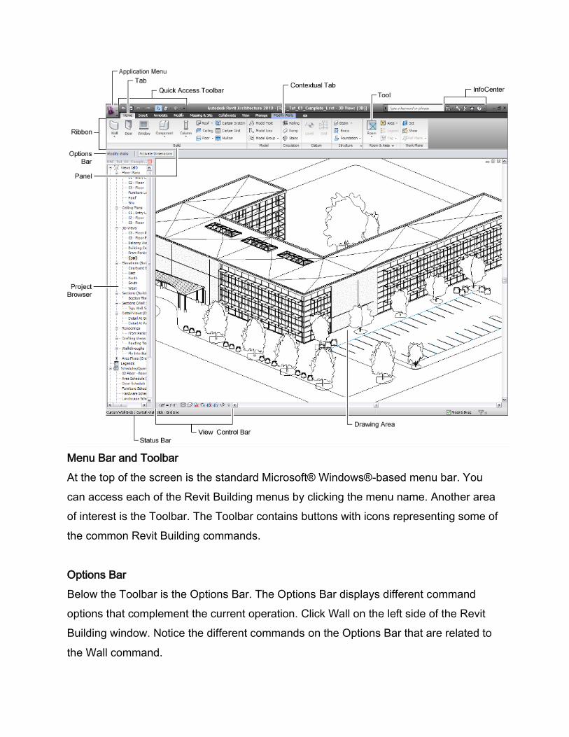
Menu Bar and Toolbar
At the top of the screen is the standard Microsoft® Windows®-based menu bar. You
can access each of the Revit Building menus by clicking the menu name. Another area
of interest is the Toolbar. The Toolbar contains buttons with icons representing some of
the common Revit Building commands.
Options Bar
Below the Toolbar is the Options Bar. The Options Bar displays different command
options that complement the current operation. Click Wall on the left side of the Revit
Building window. Notice the different commands on the Options Bar that are related to
the Wall command.
Type Selector
On the Ribbon bar is the Type Selector. The Type Selector lists different types of
families to add to a project. You can choose other wall types by selecting them from the
drop-down menu of the Type Selector.
Properties Button
To the left on the Ribbon Bar, is the Properties button . Use this button to change the
different property values of your components.
Project Browser
To the right of the Design Bar is the Project Browser. The Project Browser is a listing of
all the views, families, and groups in the project. You can select any of the items listed
in the Project Browser. A convenient way to open the views is to double-click the view
names in the Project Browser list.
Status Bar
On the lower left corner of the interface is the Status Bar. This displays the status of the
current command or the name of a highlighted element.
Starting Your Project
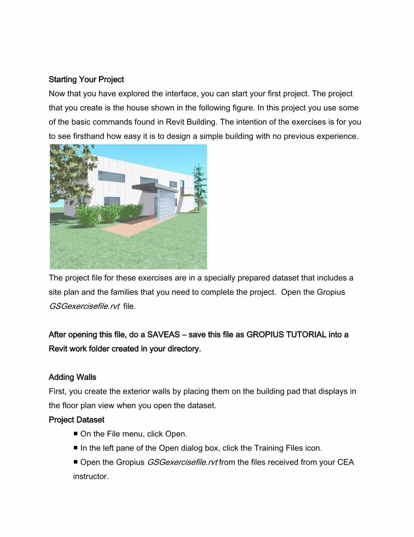
Now that you have explored the interface, you can start your first project. The project
that you create is the house shown in the following figure. In this project you use some
of the basic commands found in Revit Building. The intention of the exercises is for you
to see firsthand how easy it is to design a simple building with no previous experience.
The project file for these exercises are in a specially prepared dataset that includes a
site plan and the families that you need to complete the project. Open the Gropius
GSGexercisefile.rvt file.
After opening this file, do a SAVEAS – save this file as GROPIUS TUTORIAL into a
Revit work folder created in your directory.
Adding Walls
First, you create the exterior walls by placing them on the building pad that displays in
the floor plan view when you open the dataset.
Project Dataset
■ On the File menu, click Open.
■ In the left pane of the Open dialog box, click the Training Files icon.
■ Open the Gropius GSGexercisefile.rvt from the files received from your CEA
instructor.
1. On the Home tab, click Wall.
2. On the Options Bar, select Level 2 for Height.
3. On the Options Bar, select Finish Face: Exterior
This option places the walls on the building pad by their exterior faces. Later when you
change the wall type, the walls stay located by their exterior faces.
4. Click Draw-rectangle tool .
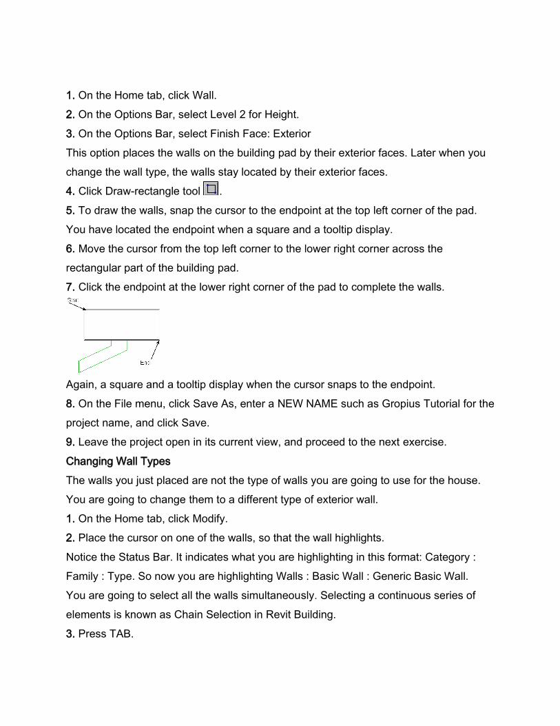
5. To draw the walls, snap the cursor to the endpoint at the top left corner of the pad.
You have located the endpoint when a square and a tooltip display.
6. Move the cursor from the top left corner to the lower right corner across the
rectangular part of the building pad.
7. Click the endpoint at the lower right corner of the pad to complete the walls.
Again, a square and a tooltip display when the cursor snaps to the endpoint.
8. On the File menu, click Save As, enter a NEW NAME such as Gropius Tutorial for the
project name, and click Save.
9. Leave the project open in its current view, and proceed to the next exercise.
Changing Wall Types
The walls you just placed are not the type of walls you are going to use for the house.
You are going to change them to a different type of exterior wall.
1. On the Home tab, click Modify.
2. Place the cursor on one of the walls, so that the wall highlights.
Notice the Status Bar. It indicates what you are highlighting in this format: Category :
Family : Type. So now you are highlighting Walls : Basic Wall : Generic Basic Wall.
You are going to select all the walls simultaneously. Selecting a continuous series of
elements is known as Chain Selection in Revit Building.
3. Press TAB.
Notice that all the walls highlight. Also notice the Status Bar indicates Chain of Walls.
4. Click to select the walls.
All the walls are now selected and are displayed in red (or blue – depending on the
REVIT color selection).
5. In the Element-Change Element Type, click Basic Wall: Wood Stud w/Vertical Siding.
The walls change to the new type.
6. Press CTRL+S to save the file.
7. Leave the project open in its current view, and proceed to the next exercise.
Adding Building Datums
In this part of the exercise, you create a new level for the roof and a level for the parapet
above the roof.
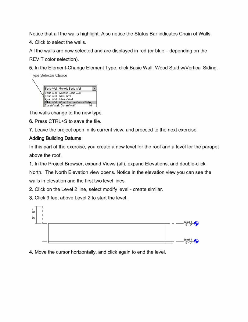
1. In the Project Browser, expand Views (all), expand Elevations, and double-click
North. The North Elevation view opens. Notice in the elevation view you can see the
walls in elevation and the first two level lines.
2. Click on the Level 2 line, select modify level - create similar.
3. Click 9 feet above Level 2 to start the level.
4. Move the cursor horizontally, and click again to end the level.
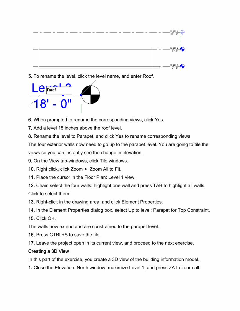
5. To rename the level, click the level name, and enter Roof.
6. When prompted to rename the corresponding views, click Yes.
7. Add a level 18 inches above the roof level.
8. Rename the level to Parapet, and click Yes to rename corresponding views.
The four exterior walls now need to go up to the parapet level. You are going to tile the
views so you can instantly see the change in elevation.
9. On the View tab-windows, click Tile windows.
10. Right click, click Zoom ➤ Zoom All to Fit.
11. Place the cursor in the Floor Plan: Level 1 view.
12. Chain select the four walls: highlight one wall and press TAB to highlight all walls.
Click to select them.
13. Right-click in the drawing area, and click Element Properties.
14. In the Element Properties dialog box, select Up to level: Parapet for Top Constraint.
15. Click OK.
The walls now extend and are constrained to the parapet level.
16. Press CTRL+S to save the file.
17. Leave the project open in its current view, and proceed to the next exercise.
Creating a 3D View
In this part of the exercise, you create a 3D view of the building information model.
1. Close the Elevation: North window, maximize Level 1, and press ZA to zoom all.
2. On the View toolbar, click to create a new 3D view.
3. Reorient the building model:
■ On the Navigation wheel, choose the Orbit tool .
■ OR Press the mouse wheel down and hold SHIFT, and spin the building model by
dragging one of the corners in any direction.
■ To finish spinning the building model, press ESC.
4. In the Project Browser expand 3D Views.
5. To give the view a unique name, right-click {3D}, and click Rename.
6. Enter the name and press OK.
7. Press CTRL+S to save the file.
8. Leave the project open in its current view, and proceed to the next exercise.
Modifying the Shell
In this part of the exercise, you are going to split a wall and vary its height. You attach
the wall to a cantilevered space you create later.
1. In the Project Browser under Floor Plans, double-click Level 1.
2. Right-click in the drawing area, and click Zoom to Fit.
3. Click on the Modify-Edit-Split
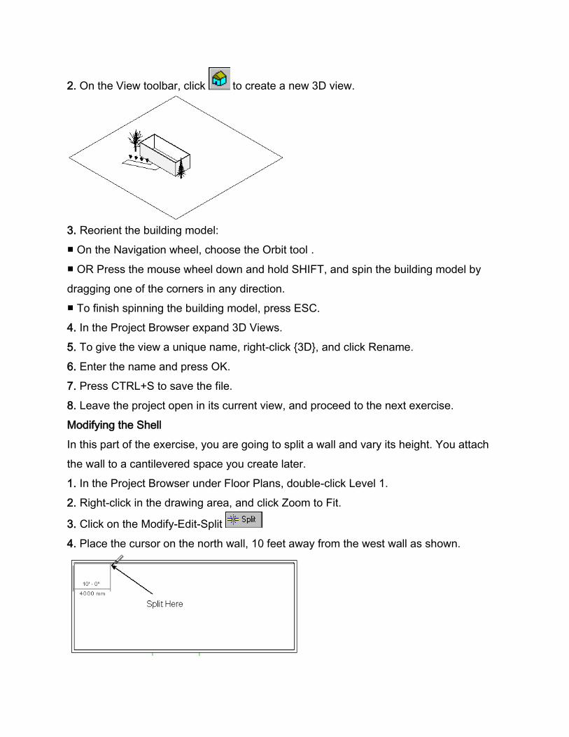
4. Place the cursor on the north wall, 10 feet away from the west wall as shown.
5. Click to split the wall.
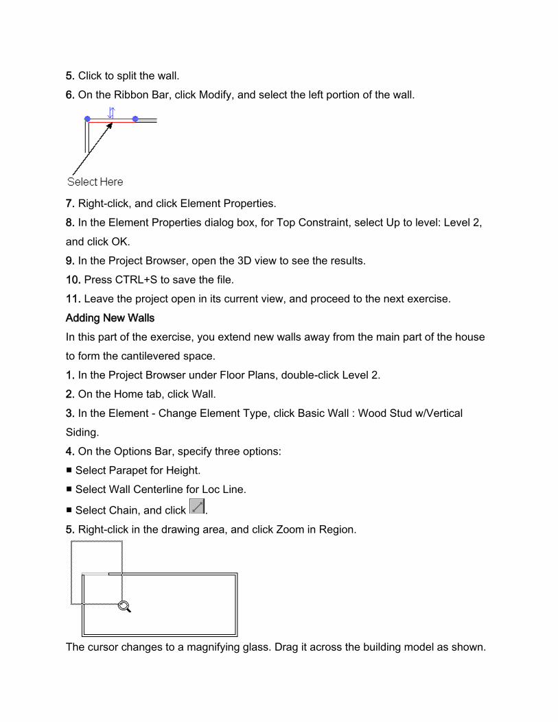
6. On the Ribbon Bar, click Modify, and select the left portion of the wall.
7. Right-click, and click Element Properties.
8. In the Element Properties dialog box, for Top Constraint, select Up to level: Level 2,
and click OK.
9. In the Project Browser, open the 3D view to see the results.
10. Press CTRL+S to save the file.
11. Leave the project open in its current view, and proceed to the next exercise.
Adding New Walls
In this part of the exercise, you extend new walls away from the main part of the house
to form the cantilevered space.
1. In the Project Browser under Floor Plans, double-click Level 2.
2. On the Home tab, click Wall.
3. In the Element - Change Element Type, click Basic Wall : Wood Stud w/Vertical
Siding.
4. On the Options Bar, specify three options:
■ Select Parapet for Height.
■ Select Wall Centerline for Loc Line.
■ Select Chain, and click .
5. Right-click in the drawing area, and click Zoom in Region.
The cursor changes to a magnifying glass. Drag it across the building model as shown.
6. To sketch the first cantilevered wall, make sure the cursor snaps to the endpoint
along the centerline of the vertical wall. Watch the Status Bar as you place the cursor.
Do not place the cursor so that it snaps at the intersection of the walls. An intersection is
indicated by an X.
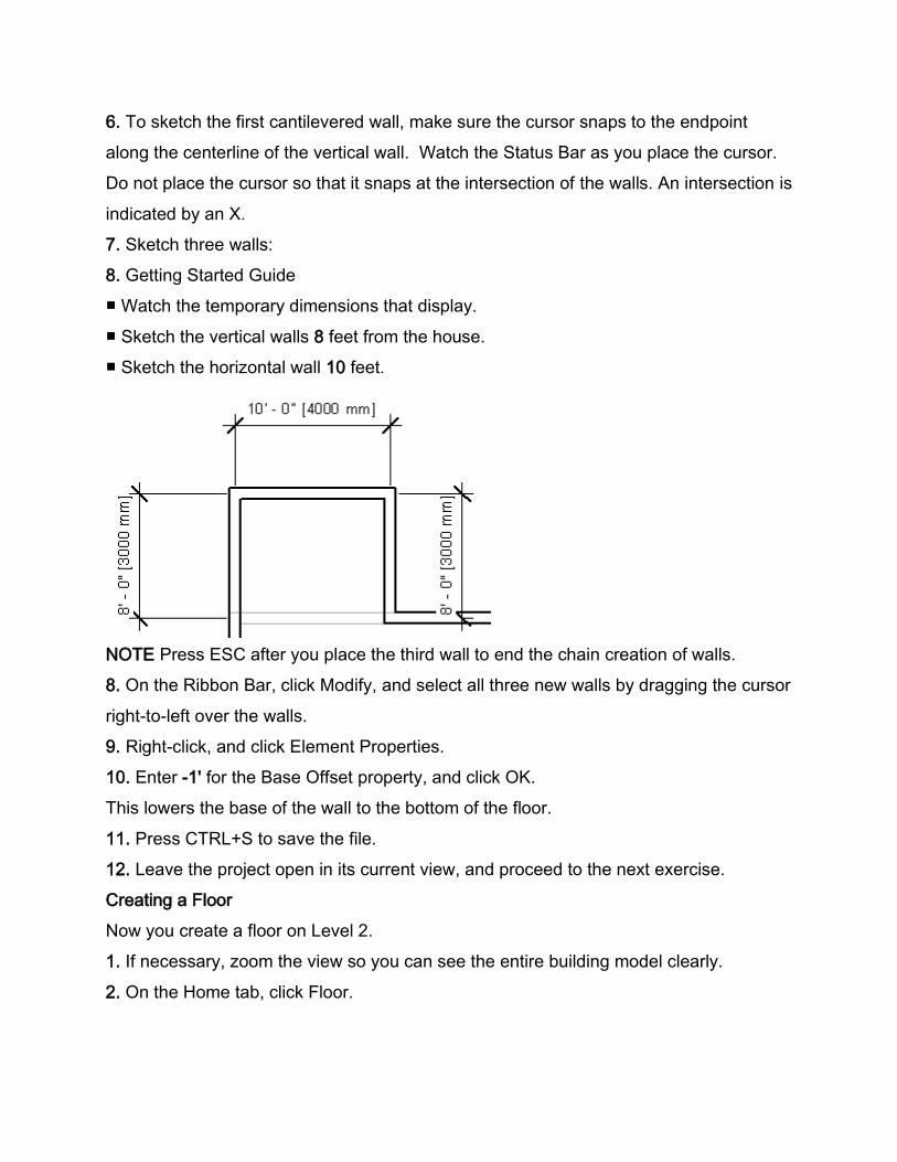
7. Sketch three walls:
8. Getting Started Guide
■ Watch the temporary dimensions that display.
■ Sketch the vertical walls 8 feet from the house.
■ Sketch the horizontal wall 10 feet.
NOTE Press ESC after you place the third wall to end the chain creation of walls.
8. On the Ribbon Bar, click Modify, and select all three new walls by dragging the cursor
right-to-left over the walls.
9. Right-click, and click Element Properties.
10. Enter -1' for the Base Offset property, and click OK.
This lowers the base of the wall to the bottom of the floor.
11. Press CTRL+S to save the file.
12. Leave the project open in its current view, and proceed to the next exercise.
Creating a Floor
Now you create a floor on Level 2.
1. If necessary, zoom the view so you can see the entire building model clearly.
2. On the Home tab, click Floor.
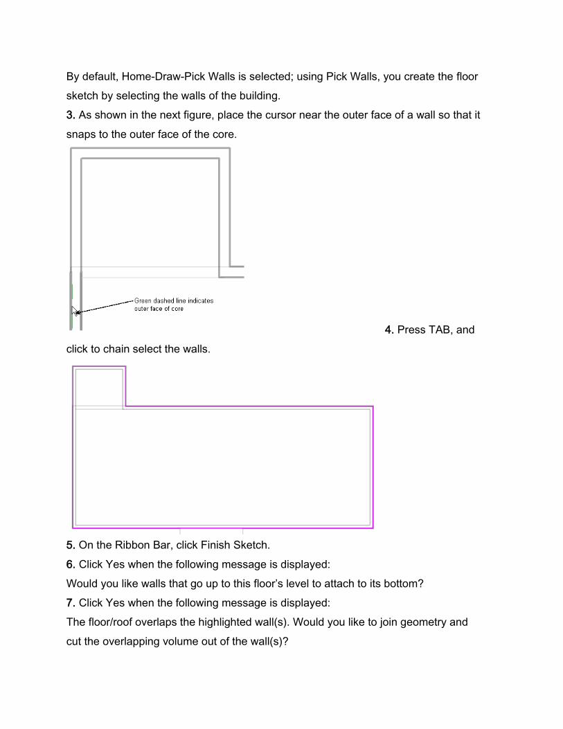
By default, Home-Draw-Pick Walls is selected; using Pick Walls, you create the floor
sketch by selecting the walls of the building.
3. As shown in the next figure, place the cursor near the outer face of a wall so that it
snaps to the outer face of the core.
4. Press TAB, and
click to chain select the walls.
5. On the Ribbon Bar, click Finish Sketch.
6. Click Yes when the following message is displayed:
Would you like walls that go up to this floor’s level to attach to its bottom?
7. Click Yes when the following message is displayed:
The floor/roof overlaps the highlighted wall(s). Would you like to join geometry and
cut the overlapping volume out of the wall(s)?
8. Press CTRL+S to save the file.
9. Leave the project open in its current view, and proceed to the next exercise.
Adding a Roof
Now you add a roof to the top of the house.
1. In the Project Browser under Floor Plans, double-click Roof.
2. If necessary, zoom the view so you can see the entire building model clearly.
3. On the Home tab, click Roof ➤ Roof by Footprint.
4. On the Options Bar, select Extend to wall core.
You create the roof the same way you created the floor.
5. With the Pick Walls command selected, place the cursor near the outer face of a wall
so that it snaps to the outer face of the core.
6. Press TAB , and click to chain select the walls.
The roof sketch displays with the walls highlighted.
7. Click Finish Roof.
8. Click Yes when the following message is displayed:
The floor/roof overlaps the highlighted wall(s). Would you like to join geometry and
cut the overlapping volume out of the wall(s)?
9. Open the 3D view to see the results.
10. Press CTRL+S to save the file.
11. Leave the project open in its current view, and proceed to the next exercise.
Adding Interior Features
Now you add some interior features to the floor plan layout.
1. In the Project Browser under Floor Plans, double-click Level 1.
2. On the Home tab, click Wall.
3. In the Element –Element Type, click Basic Wall : Interior Wall.
4. Clear Chain, and select .
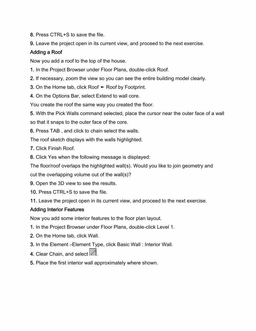
5. Place the first interior wall approximately where shown.
6. Place the remaining interior walls approximately where shown.
Do not be concerned with exact placement at this time. You will use dimensions to
space these walls at equal distances from each other.
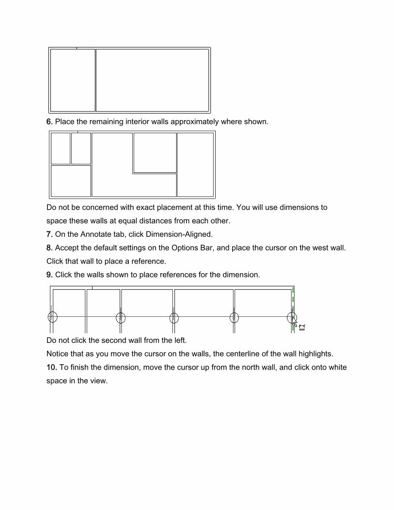
7. On the Annotate tab, click Dimension-Aligned.
8. Accept the default settings on the Options Bar, and place the cursor on the west wall.
Click that wall to place a reference.
9. Click the walls shown to place references for the dimension.
Do not click the second wall from the left.
Notice that as you move the cursor on the walls, the centerline of the wall highlights.
10. To finish the dimension, move the cursor up from the north wall, and click onto white
space in the view.
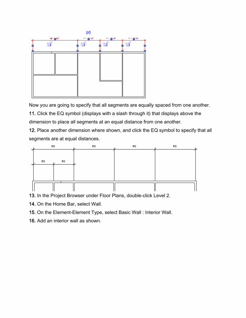
Now you are going to specify that all segments are equally spaced from one another.
11. Click the EQ symbol (displays with a slash through it) that displays above the
dimension to place all segments at an equal distance from one another.
12. Place another dimension where shown, and click the EQ symbol to specify that all
segments are at equal distances.
13. In the Project Browser under Floor Plans, double-click Level 2.
14. On the Home Bar, select Wall.
15. On the Element-Element Type, select Basic Wall : Interior Wall.
16. Add an interior wall as shown.
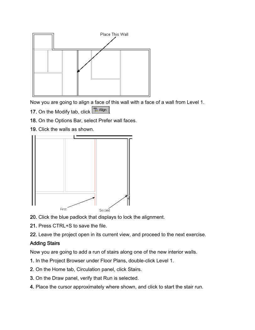
Now you are going to align a face of this wall with a face of a wall from Level 1.
17. On the Modify tab, click .
18. On the Options Bar, select Prefer wall faces.
19. Click the walls as shown.
20. Click the blue padlock that displays to lock the alignment.
21. Press CTRL+S to save the file.
22. Leave the project open in its current view, and proceed to the next exercise.
Adding Stairs
Now you are going to add a run of stairs along one of the new interior walls.
1. In the Project Browser under Floor Plans, double-click Level 1.
2. On the Home tab, Circulation panel, click Stairs.
3. On the Draw panel, verify that Run is selected.
4. Place the cursor approximately where shown, and click to start the stair run.
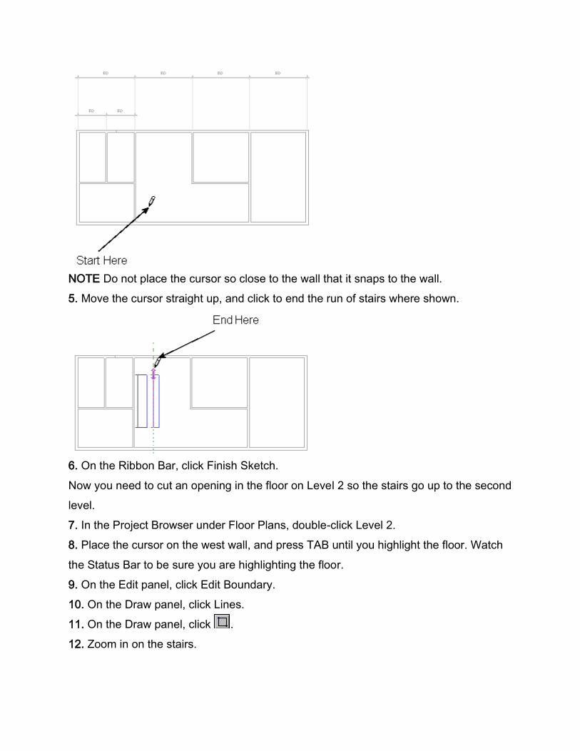
NOTE Do not place the cursor so close to the wall that it snaps to the wall.
5. Move the cursor straight up, and click to end the run of stairs where shown.
6. On the Ribbon Bar, click Finish Sketch.
Now you need to cut an opening in the floor on Level 2 so the stairs go up to the second
level.
7. In the Project Browser under Floor Plans, double-click Level 2.
8. Place the cursor on the west wall, and press TAB until you highlight the floor. Watch
the Status Bar to be sure you are highlighting the floor.
9. On the Edit panel, click Edit Boundary.
10. On the Draw panel, click Lines.
11. On the Draw panel, click .
12. Zoom in on the stairs.
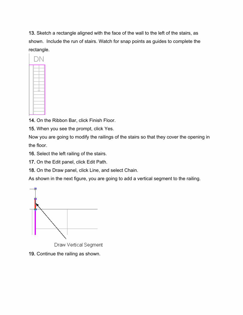
13. Sketch a rectangle aligned with the face of the wall to the left of the stairs, as
shown. Include the run of stairs. Watch for snap points as guides to complete the
rectangle.
14. On the Ribbon Bar, click Finish Floor.
15. When you see the prompt, click Yes.
Now you are going to modify the railings of the stairs so that they cover the opening in
the floor.
16. Select the left railing of the stairs.
17. On the Edit panel, click Edit Path.
18. On the Draw panel, click Line, and select Chain.
As shown in the next figure, you are going to add a vertical segment to the railing.
19. Continue the railing as shown.
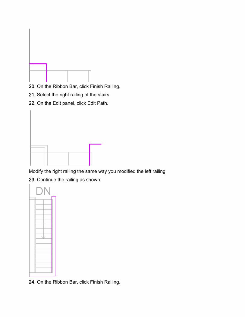
20. On the Ribbon Bar, click Finish Railing.
21. Select the right railing of the stairs.
22. On the Edit panel, click Edit Path.
Modify the right railing the same way you modified the left railing.
23. Continue the railing as shown.
24. On the Ribbon Bar, click Finish Railing.
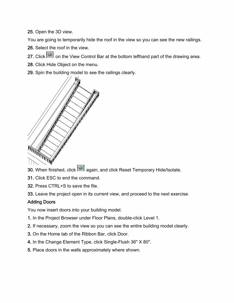
25. Open the 3D view.
You are going to temporarily hide the roof in the view so you can see the new railings.
26. Select the roof in the view.
27. Click on the View Control Bar at the bottom lefthand part of the drawing area.
28. Click Hide Object on the menu.
29. Spin the building model to see the railings clearly.
30. When finished, click again, and click Reset Temporary Hide/Isolate.
31. Click ESC to end the command.
32. Press CTRL+S to save the file.
33. Leave the project open in its current view, and proceed to the next exercise.
Adding Doors
You now insert doors into your building model.
1. In the Project Browser under Floor Plans, double-click Level 1.
2. If necessary, zoom the view so you can see the entire building model clearly.
3. On the Home tab of the Ribbon Bar, click Door.
4. In the Change Element Type, click Single-Flush 36'' X 80''.
5. Place doors in the walls approximately where shown.
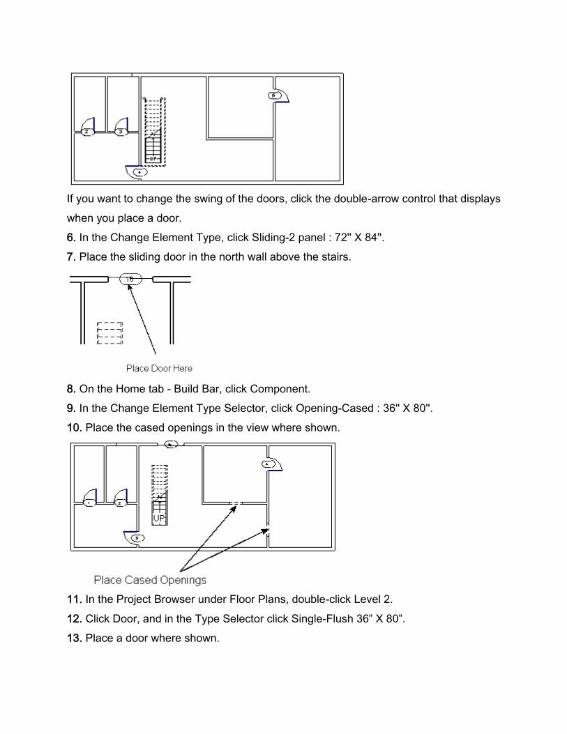
If you want to change the swing of the doors, click the double-arrow control that displays
when you place a door.
6. In the Change Element Type, click Sliding-2 panel : 72'' X 84''.
7. Place the sliding door in the north wall above the stairs.
8. On the Home tab - Build Bar, click Component.
9. In the Change Element Type Selector, click Opening-Cased : 36'' X 80''.
10. Place the cased openings in the view where shown.
11. In the Project Browser under Floor Plans, double-click Level 2.
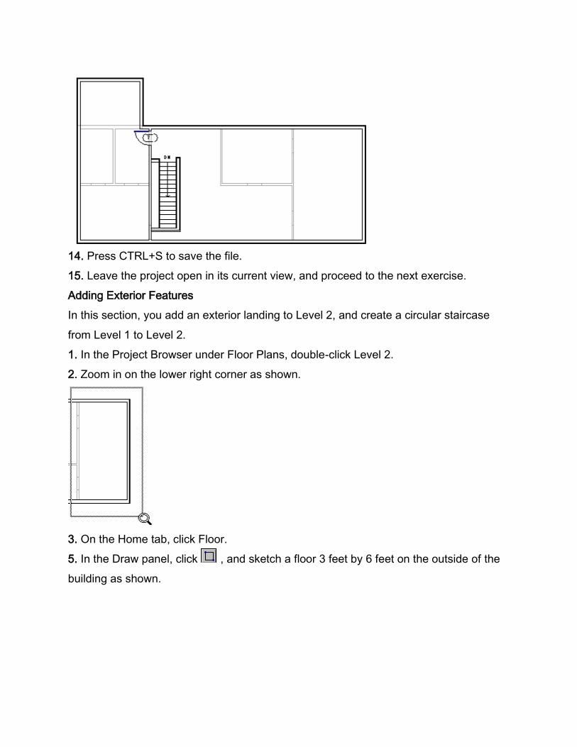
12. Click Door, and in the Type Selector click Single-Flush 36” X 80”.
13. Place a door where shown.
14. Press CTRL+S to save the file.
15. Leave the project open in its current view, and proceed to the next exercise.
Adding Exterior Features
In this section, you add an exterior landing to Level 2, and create a circular staircase
from Level 1 to Level 2.
1. In the Project Browser under Floor Plans, double-click Level 2.
2. Zoom in on the lower right corner as shown.
3. On the Home tab, click Floor.
5. In the Draw panel, click , and sketch a floor 3 feet by 6 feet on the outside of the
building as shown.
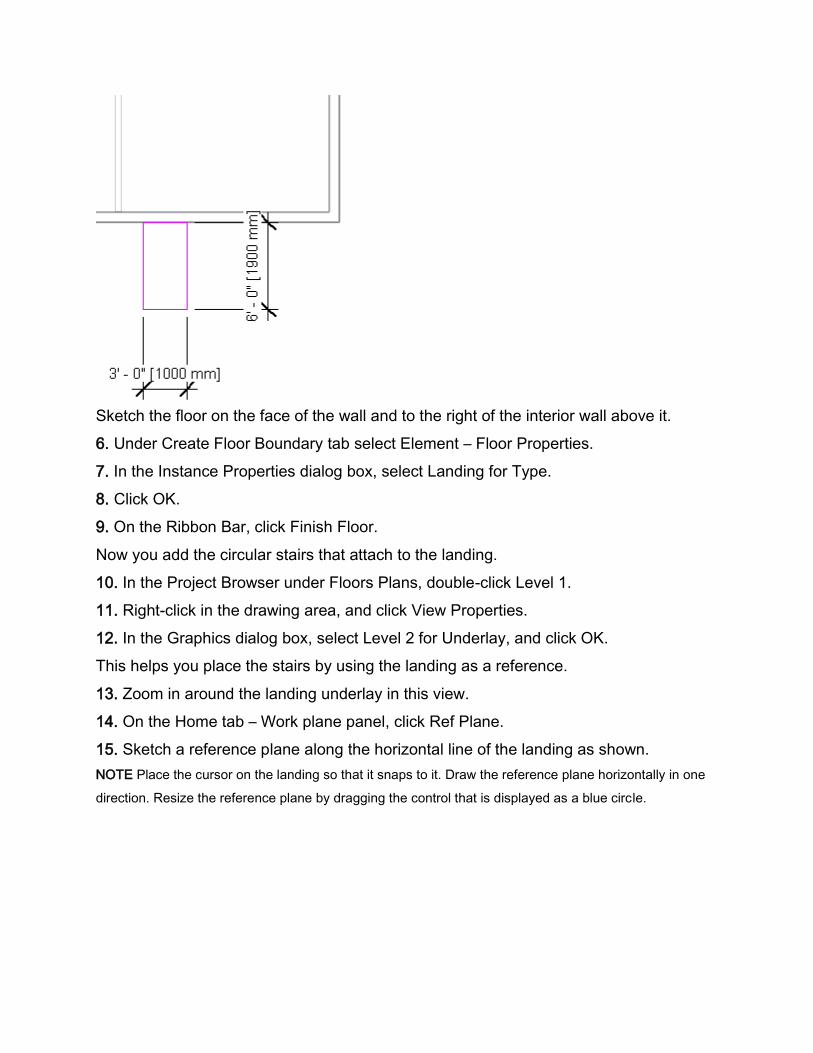
Sketch the floor on the face of the wall and to the right of the interior wall above it.
6. Under Create Floor Boundary tab select Element – Floor Properties.
7. In the Instance Properties dialog box, select Landing for Type.
8. Click OK.
9. On the Ribbon Bar, click Finish Floor.
Now you add the circular stairs that attach to the landing.
10. In the Project Browser under Floors Plans, double-click Level 1.
11. Right-click in the drawing area, and click View Properties.
12. In the Graphics dialog box, select Level 2 for Underlay, and click OK.
This helps you place the stairs by using the landing as a reference.
13. Zoom in around the landing underlay in this view.
14. On the Home tab – Work plane panel, click Ref Plane.
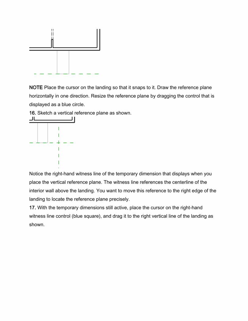
15. Sketch a reference plane along the horizontal line of the landing as shown.
NOTE Place the cursor on the landing so that it snaps to it. Draw the reference plane horizontally in one
direction. Resize the reference plane by dragging the control that is displayed as a blue circle.
NOTE Place the cursor on the landing so that it snaps to it. Draw the reference plane
horizontally in one direction. Resize the reference plane by dragging the control that is
displayed as a blue circle.
16. Sketch a vertical reference plane as shown.
Notice the right-hand witness line of the temporary dimension that displays when you
place the vertical reference plane. The witness line references the centerline of the
interior wall above the landing. You want to move this reference to the right edge of the
landing to locate the reference plane precisely.
17. With the temporary dimensions still active, place the cursor on the right-hand
witness line control (blue square), and drag it to the right vertical line of the landing as
shown.
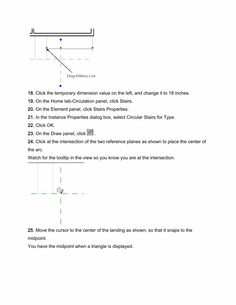
18. Click the temporary dimension value on the left, and change it to 18 inches.
19. On the Home tab-Circulation panel, click Stairs.
20. On the Element panel, click Stairs Properties.
21. In the Instance Properties dialog box, select Circular Stairs for Type.
22. Click OK.
23. On the Draw panel, click .
24. Click at the intersection of the two reference planes as shown to place the center of
the arc.
Watch for the tooltip in the view so you know you are at the intersection.
25. Move the cursor to the center of the landing as shown, so that it snaps to the
midpoint.
You have the midpoint when a triangle is displayed.
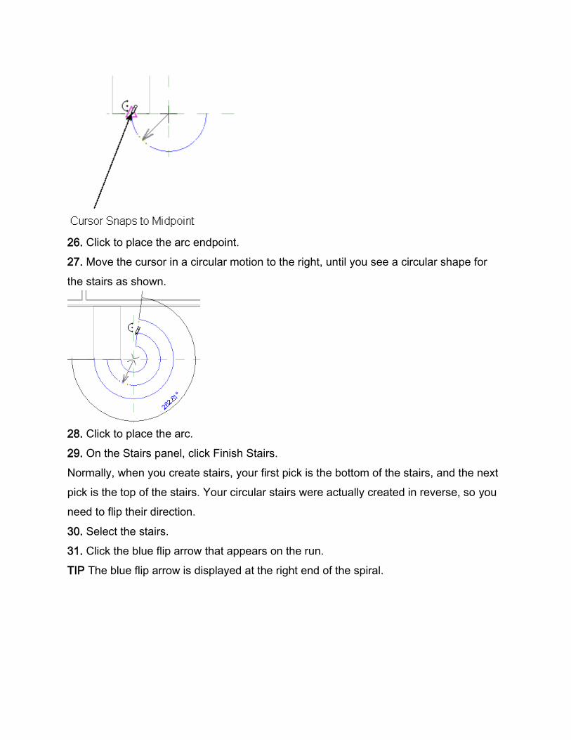
26. Click to place the arc endpoint.
27. Move the cursor in a circular motion to the right, until you see a circular shape for
the stairs as shown.
28. Click to place the arc.
29. On the Stairs panel, click Finish Stairs.
Normally, when you create stairs, your first pick is the bottom of the stairs, and the next
pick is the top of the stairs. Your circular stairs were actually created in reverse, so you
need to flip their direction.
30. Select the stairs.
31. Click the blue flip arrow that appears on the run.
TIP The blue flip arrow is displayed at the right end of the spiral.
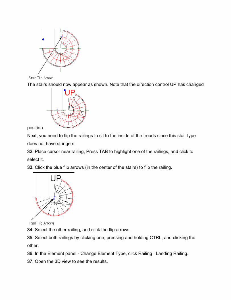
The stairs should now appear as shown. Note that the direction control UP has changed
position.
Next, you need to flip the railings to sit to the inside of the treads since this stair type
does not have stringers.
32. Place cursor near railing, Press TAB to highlight one of the railings, and click to
select it.
33. Click the blue flip arrows (in the center of the stairs) to flip the railing.
34. Select the other railing, and click the flip arrows.
35. Select both railings by clicking one, pressing and holding CTRL, and clicking the
other.
36. In the Element panel - Change Element Type, click Railing : Landing Railing.
37. Open the 3D view to see the results.
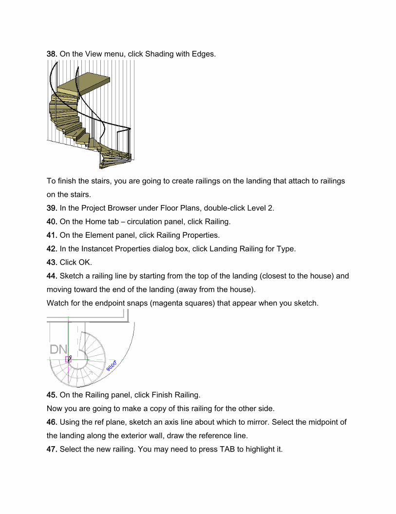
38. On the View menu, click Shading with Edges.
To finish the stairs, you are going to create railings on the landing that attach to railings
on the stairs.
39. In the Project Browser under Floor Plans, double-click Level 2.
40. On the Home tab – circulation panel, click Railing.
41. On the Element panel, click Railing Properties.
42. In the Instancet Properties dialog box, click Landing Railing for Type.
43. Click OK.
44. Sketch a railing line by starting from the top of the landing (closest to the house) and
moving toward the end of the landing (away from the house).
Watch for the endpoint snaps (magenta squares) that appear when you sketch.
45. On the Railing panel, click Finish Railing.
Now you are going to make a copy of this railing for the other side.
46. Using the ref plane, sketch an axis line about which to mirror. Select the midpoint of
the landing along the exterior wall, draw the reference line.
47. Select the new railing. You may need to press TAB to highlight it.
48.. On the Modify panel, click Mirror.
49. On the Options Bar, verify that Copy is selected.
50. Select the reference line to mirror the railing across it..
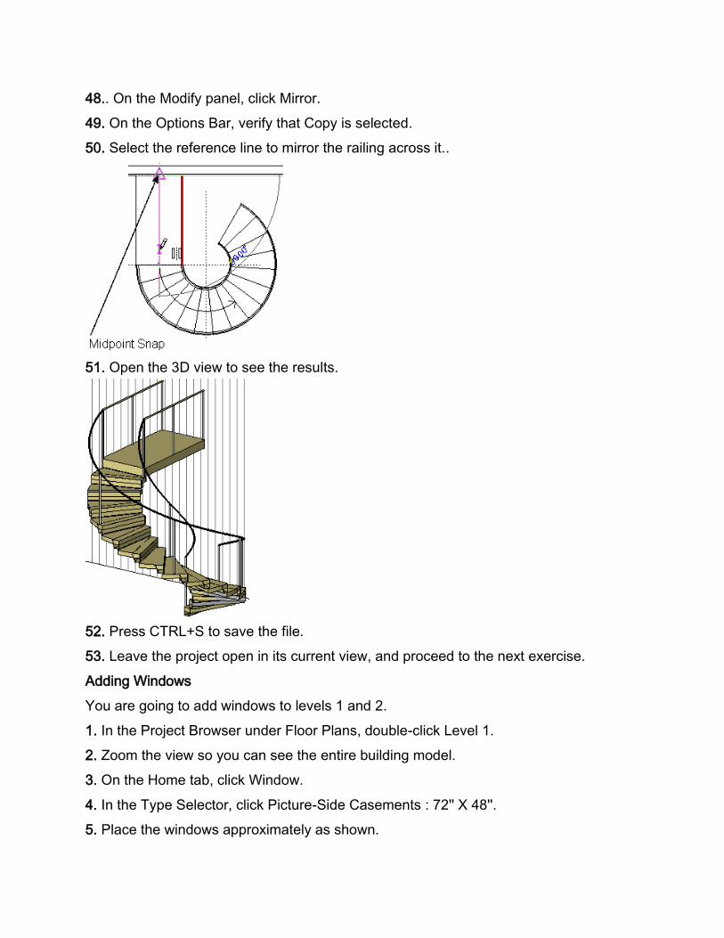
51. Open the 3D view to see the results.
52. Press CTRL+S to save the file.
53. Leave the project open in its current view, and proceed to the next exercise.
Adding Windows
You are going to add windows to levels 1 and 2.
1. In the Project Browser under Floor Plans, double-click Level 1.
2. Zoom the view so you can see the entire building model.
3. On the Home tab, click Window.
4. In the Type Selector, click Picture-Side Casements : 72'' X 48''.
5. Place the windows approximately as shown.
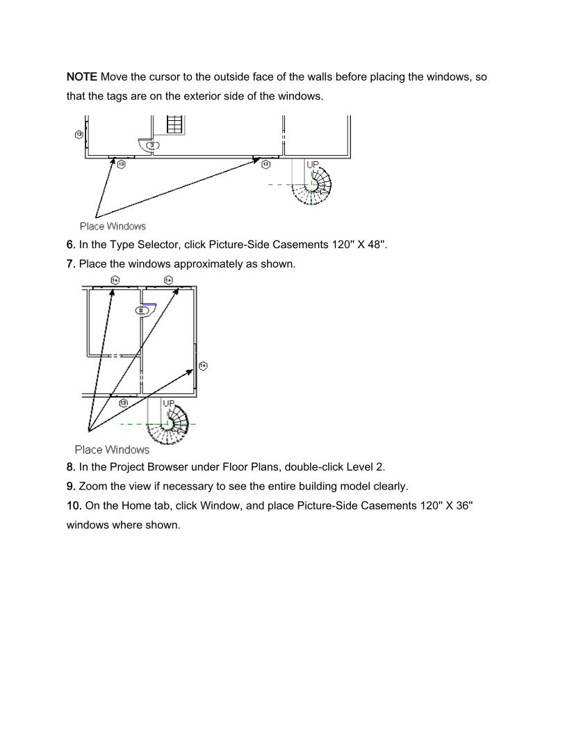
NOTE Move the cursor to the outside face of the walls before placing the windows, so
that the tags are on the exterior side of the windows.
6. In the Type Selector, click Picture-Side Casements 120'' X 48''.
7. Place the windows approximately as shown.
8. In the Project Browser under Floor Plans, double-click Level 2.
9. Zoom the view if necessary to see the entire building model clearly.
10. On the Home tab, click Window, and place Picture-Side Casements 120'' X 36''
windows where shown.
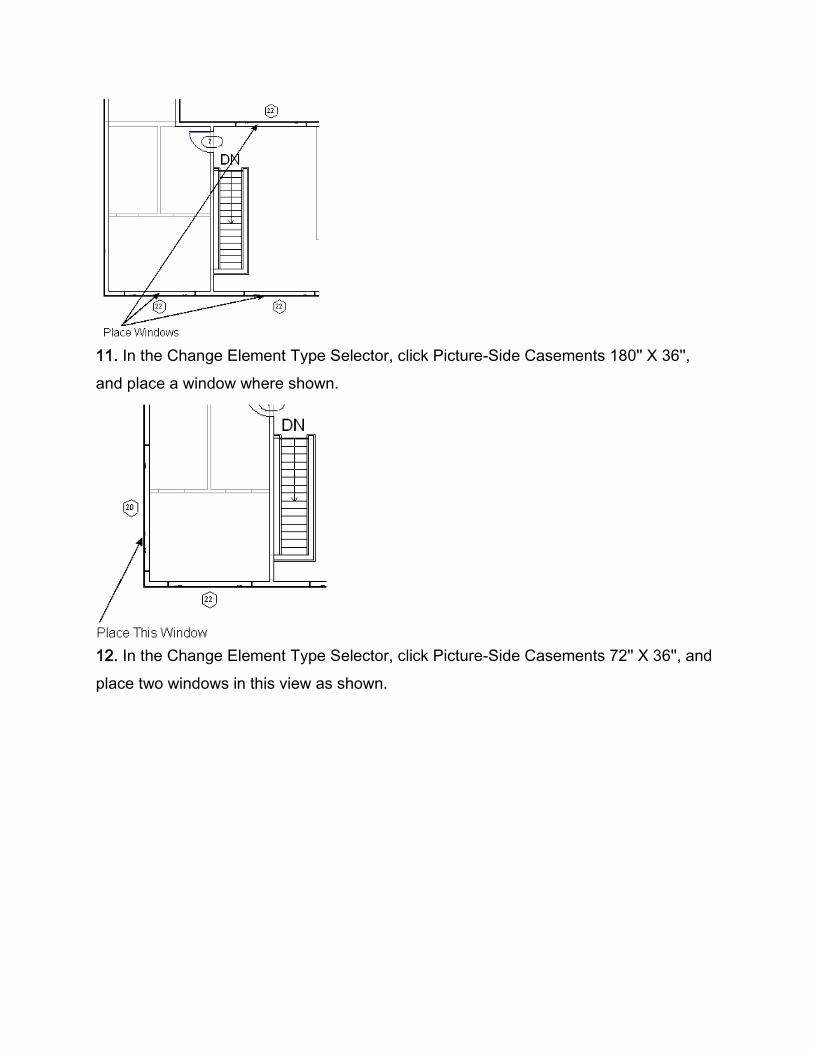
11. In the Change Element Type Selector, click Picture-Side Casements 180'' X 36'',
and place a window where shown.
12. In the Change Element Type Selector, click Picture-Side Casements 72'' X 36'', and
place two windows in this view as shown.
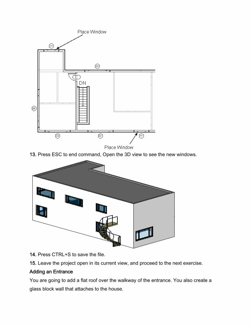
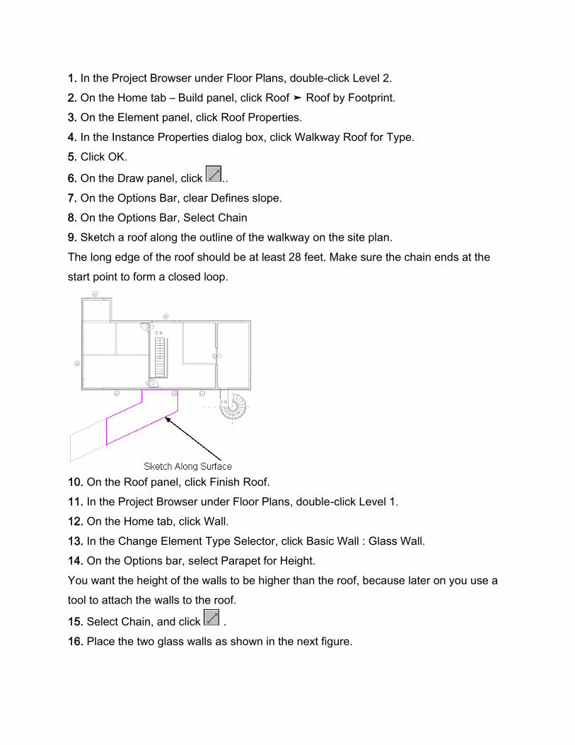
13. Press ESC to end command, Open the 3D view to see the new windows.
14. Press CTRL+S to save the file.
15. Leave the project open in its current view, and proceed to the next exercise.
Adding an Entrance
You are going to add a flat roof over the walkway of the entrance. You also create a
glass block wall that attaches to the house.
1. In the Project Browser under Floor Plans, double-click Level 2.
2. On the Home tab – Build panel, click Roof ➤ Roof by Footprint.
3. On the Element panel, click Roof Properties.
4. In the Instance Properties dialog box, click Walkway Roof for Type.
5. Click OK.
6. On the Draw panel, click ..
7. On the Options Bar, clear Defines slope.
8. On the Options Bar, Select Chain
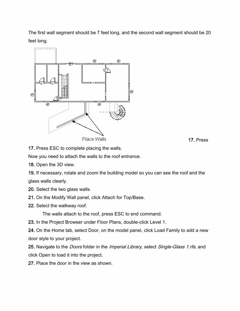
9. Sketch a roof along the outline of the walkway on the site plan.
The long edge of the roof should be at least 28 feet. Make sure the chain ends at the
start point to form a closed loop.
10. On the Roof panel, click Finish Roof.
11. In the Project Browser under Floor Plans, double-click Level 1.
12. On the Home tab, click Wall.
13. In the Change Element Type Selector, click Basic Wall : Glass Wall.
14. On the Options bar, select Parapet for Height.
You want the height of the walls to be higher than the roof, because later on you use a
tool to attach the walls to the roof.
15. Select Chain, and click .
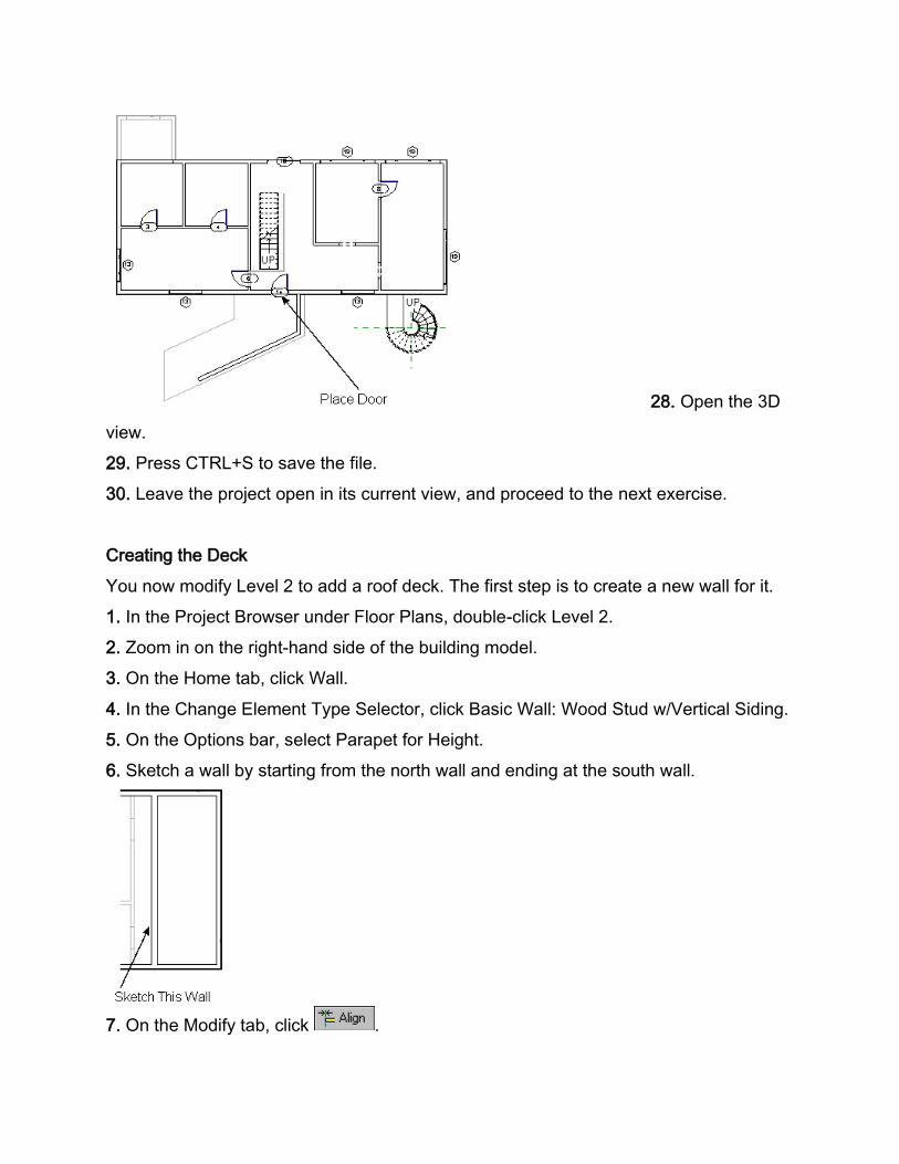
16. Place the two glass walls as shown in the next figure.
The first wall segment should be 7 feet long, and the second wall segment should be 20
feet long.
17. Press
17. Press ESC to complete placing the walls.
Now you need to attach the walls to the roof entrance.
18. Open the 3D view.
19. If necessary, rotate and zoom the building model so you can see the roof and the
glass walls clearly.
20. Select the two glass walls.
21. On the Modify Wall panel, click Attach for Top/Base.
22. Select the walkway roof.
The walls attach to the roof, press ESC to end command.
23. In the Project Browser under Floor Plans, double-click Level 1.
24. On the Home tab, select Door, on the model panel, click Load Family to add a new
door style to your project.
25. Navigate to the Doors folder in the Imperial Library, select Single-Glass 1.rfa, and
click Open to load it into the project.
27. Place the door in the view as shown.
28. Open the 3D
view.
29. Press CTRL+S to save the file.
30. Leave the project open in its current view, and proceed to the next exercise.
Creating the Deck
You now modify Level 2 to add a roof deck. The first step is to create a new wall for it.
1. In the Project Browser under Floor Plans, double-click Level 2.
2. Zoom in on the right-hand side of the building model.
3. On the Home tab, click Wall.
4. In the Change Element Type Selector, click Basic Wall: Wood Stud w/Vertical Siding.
5. On the Options bar, select Parapet for Height.
6. Sketch a wall by starting from the north wall and ending at the south wall.
7. On the Modify tab, click .
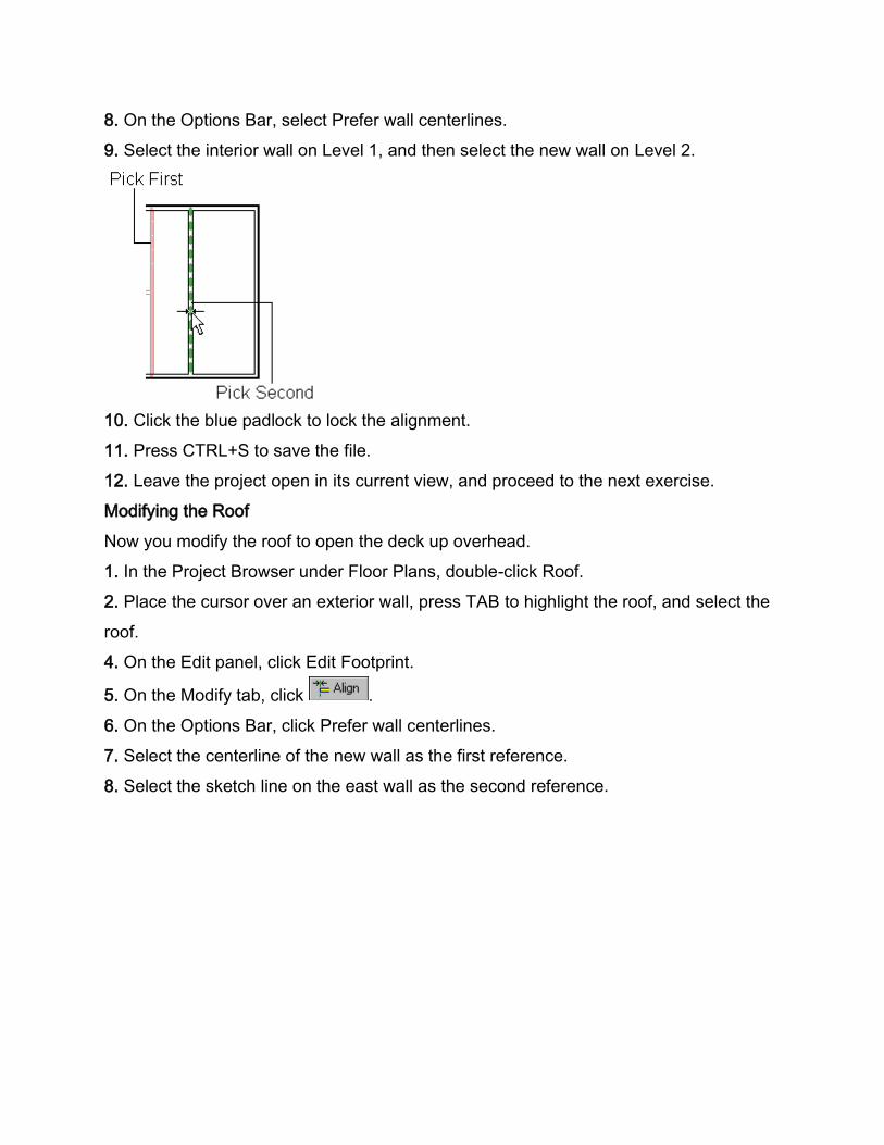
8. On the Options Bar, select Prefer wall centerlines.
9. Select the interior wall on Level 1, and then select the new wall on Level 2.
10. Click the blue padlock to lock the alignment.
11. Press CTRL+S to save the file.
12. Leave the project open in its current view, and proceed to the next exercise.
Modifying the Roof
Now you modify the roof to open the deck up overhead.
1. In the Project Browser under Floor Plans, double-click Roof.
2. Place the cursor over an exterior wall, press TAB to highlight the roof, and select the
roof.
4. On the Edit panel, click Edit Footprint.
5. On the Modify tab, click .
6. On the Options Bar, click Prefer wall centerlines.
7. Select the centerline of the new wall as the first reference.
8. Select the sketch line on the east wall as the second reference.
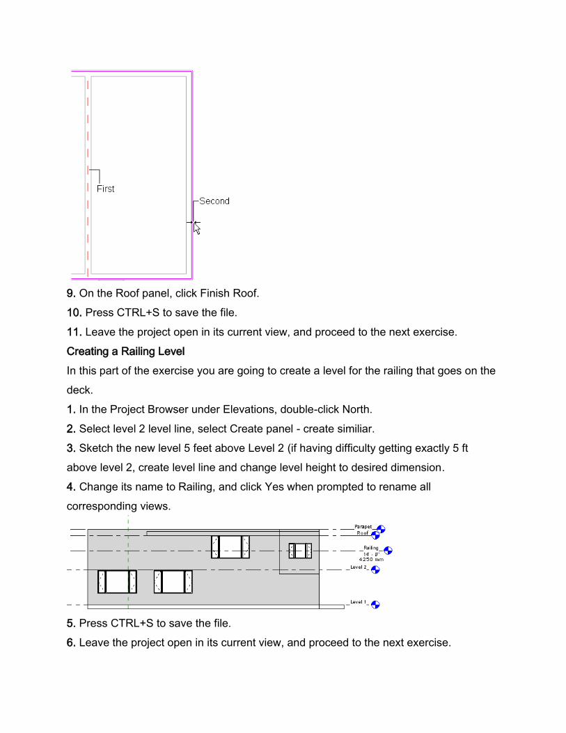
9. On the Roof panel, click Finish Roof.
10. Press CTRL+S to save the file.
11. Leave the project open in its current view, and proceed to the next exercise.
Creating a Railing Level
In this part of the exercise you are going to create a level for the railing that goes on the
deck.
1. In the Project Browser under Elevations, double-click North.
2. Select level 2 level line, select Create panel - create similiar.
3. Sketch the new level 5 feet above Level 2 (if having difficulty getting exactly 5 ft
above level 2, create level line and change level height to desired dimension.
4. Change its name to Railing, and click Yes when prompted to rename all
corresponding views.
5. Press CTRL+S to save the file.
6. Leave the project open in its current view, and proceed to the next exercise.
Modifying the Deck Walls
Now you are going to lower walls on the north and east side of the model. These walls
go up to the new railing level, so that you can attach a railing to them.
1. In the Project Browser under Floor Plans, double-click Level 2.
You need to split the north wall in order to lower it to the railing level.
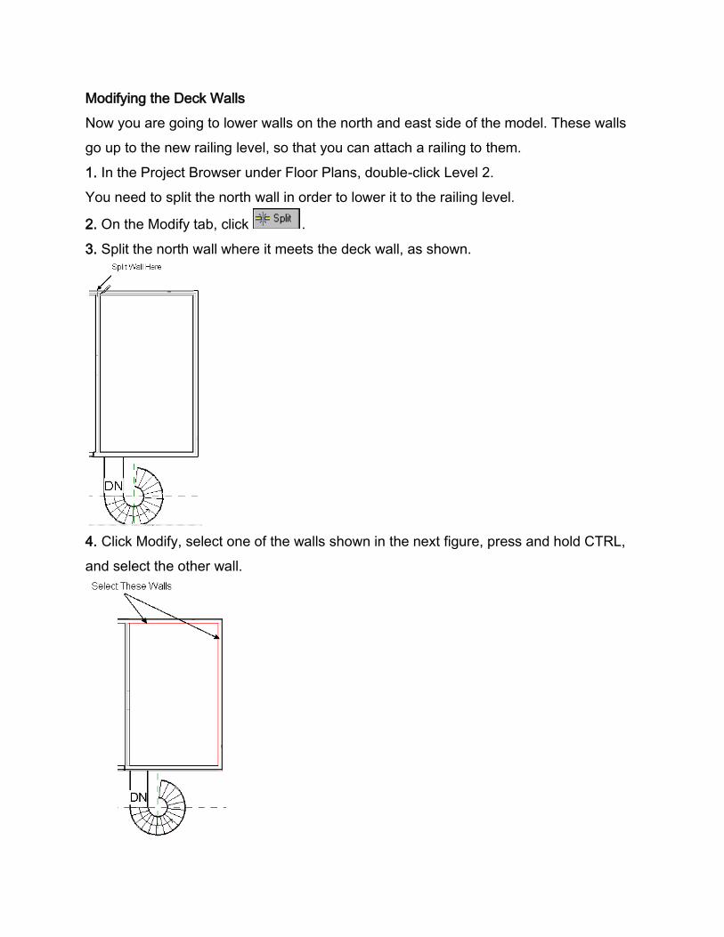
2. On the Modify tab, click .
3. Split the north wall where it meets the deck wall, as shown.
4. Click Modify, select one of the walls shown in the next figure, press and hold CTRL,
and select the other wall.
5. Right-click, and click Element Properties.
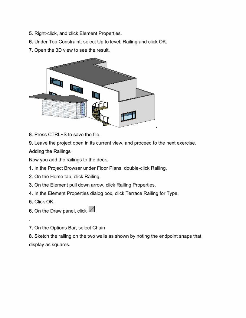
6. Under Top Constraint, select Up to level: Railing and click OK.
7. Open the 3D view to see the result.
.
8. Press CTRL+S to save the file.
9. Leave the project open in its current view, and proceed to the next exercise.
Adding the Railings
Now you add the railings to the deck.
1. In the Project Browser under Floor Plans, double-click Railing.
2. On the Home tab, click Railing.
3. On the Element pull down arrow, click Railing Properties.
4. In the Element Properties dialog box, click Terrace Railing for Type.
5. Click OK.
6. On the Draw panel, click
.
7. On the Options Bar, select Chain
8. Sketch the railing on the two walls as shown by noting the endpoint snaps that
display as squares.
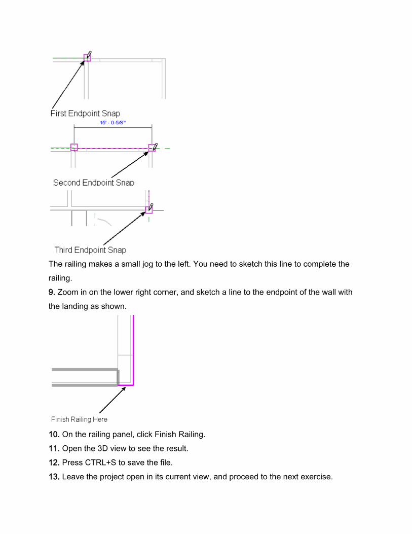
The railing makes a small jog to the left. You need to sketch this line to complete the
railing.
9. Zoom in on the lower right corner, and sketch a line to the endpoint of the wall with
the landing as shown.
10. On the railing panel, click Finish Railing.
11. Open the 3D view to see the result.
12. Press CTRL+S to save the file.
13. Leave the project open in its current view, and proceed to the next exercise.
Adding Deck Doors
You are going to add an opening to the landing and a door to the main part of the
house.
1. In the Project Browser under Floor Plans, double-click Level 2.
2. On the Home tab, click Door
3. In the Change Element Type Selector, click Sliding-2 panel : 72'' X 78''.
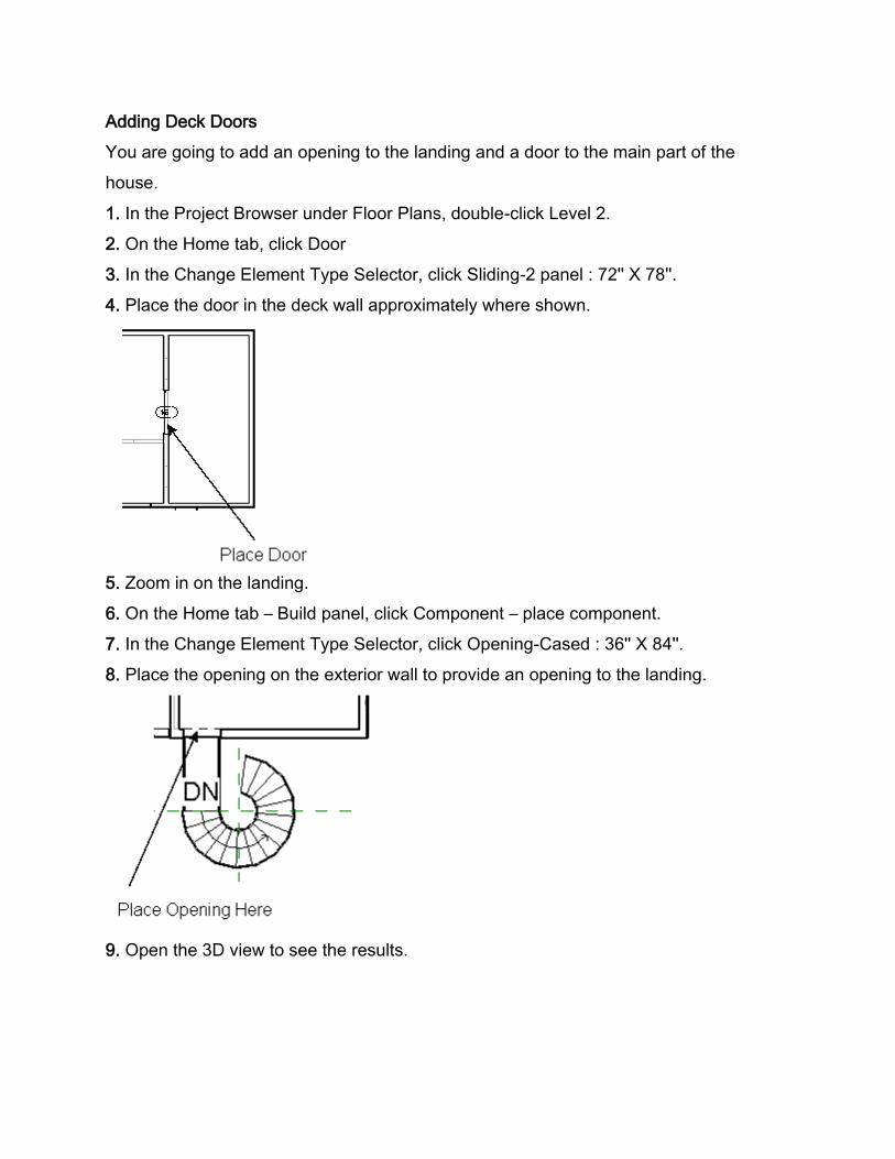
4. Place the door in the deck wall approximately where shown.
5. Zoom in on the landing.
6. On the Home tab – Build panel, click Component – place component.
7. In the Change Element Type Selector, click Opening-Cased : 36'' X 84''.
8. Place the opening on the exterior wall to provide an opening to the landing.
9. Open the 3D view to see the results.
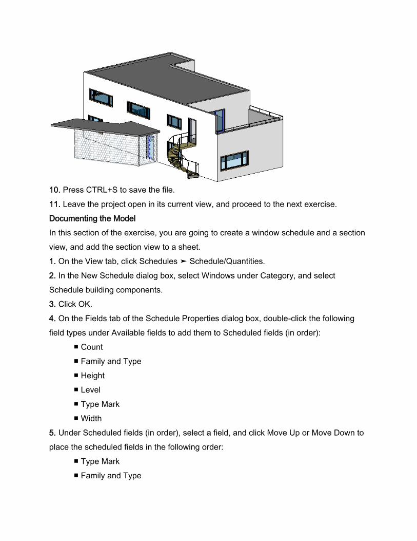
10. Press CTRL+S to save the file.
11. Leave the project open in its current view, and proceed to the next exercise.
Documenting the Model
In this section of the exercise, you are going to create a window schedule and a section
view, and add the section view to a sheet.
1. On the View tab, click Schedules ➤ Schedule/Quantities.
2. In the New Schedule dialog box, select Windows under Category, and select
Schedule building components.
3. Click OK.
4. On the Fields tab of the Schedule Properties dialog box, double-click the following
field types under Available fields to add them to Scheduled fields (in order):
■ Count
■ Family and Type
■ Height
■ Level
■ Type Mark
■ Width
5. Under Scheduled fields (in order), select a field, and click Move Up or Move Down to
place the scheduled fields in the following order:
■ Type Mark
■ Family and Type
■ Width
■ Height
■ Level
■ Count
6. Click the Sorting/Grouping tab, and select Type Mark for Sort by.
7. Select Grand Totals, and clear Itemize every instance at the bottom of the tab.
8. Click the Formatting tab, and select Family and Type from the Fields list.
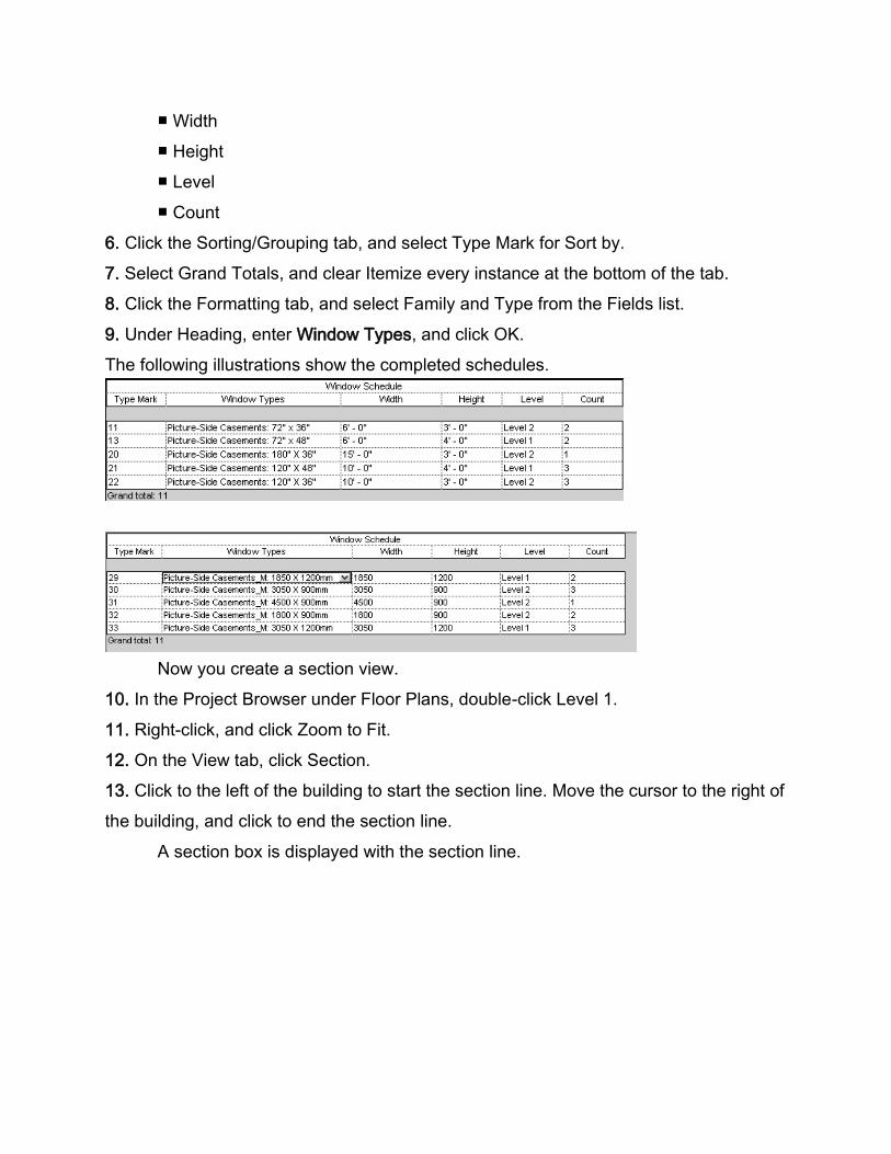
9. Under Heading, enter Window Types, and click OK.
The following illustrations show the completed schedules.
Now you create a section view.
10. In the Project Browser under Floor Plans, double-click Level 1.
11. Right-click, and click Zoom to Fit.
12. On the View tab, click Section.
13. Click to the left of the building to start the section line. Move the cursor to the right of
the building, and click to end the section line.
A section box is displayed with the section line.
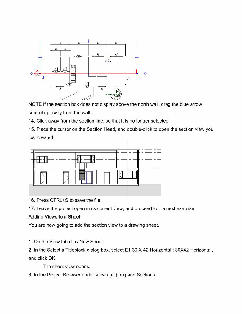
NOTE If the section box does not display above the north wall, drag the blue arrow
control up away from the wall.
14. Click away from the section line, so that it is no longer selected.
15. Place the cursor on the Section Head, and double-click to open the section view you
just created.
16. Press CTRL+S to save the file.
17. Leave the project open in its current view, and proceed to the next exercise.
Adding Views to a Sheet
You are now going to add the section view to a drawing sheet.
1. On the View tab click New Sheet.
2. In the Select a Titleblock dialog box, select E1 30 X 42 Horizontal : 30X42 Horizontal,
and click OK.
The sheet view opens.
3. In the Project Browser under Views (all), expand Sections.
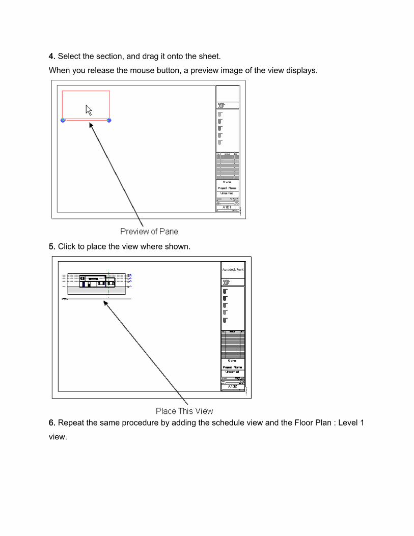
4. Select the section, and drag it onto the sheet.
When you release the mouse button, a preview image of the view displays.
5. Click to place the view where shown.
6. Repeat the same procedure by adding the schedule view and the Floor Plan : Level 1
view.
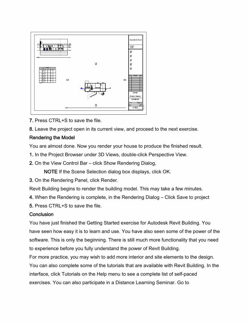
7. Press CTRL+S to save the file.
8. Leave the project open in its current view, and proceed to the next exercise.
Rendering the Model
You are almost done. Now you render your house to produce the finished result.
1. In the Project Browser under 3D Views, double-click Perspective View.
2. On the View Control Bar – click Show Rendering Dialog,
NOTE If the Scene Selection dialog box displays, click OK.
3. On the Rendering Panel, click Render.
Revit Building begins to render the building model. This may take a few minutes.
4. When the Rendering is complete, in the Rendering Dialog – Click Save to project
5. Press CTRL+S to save the file.
Conclusion
You have just finished the Getting Started exercise for Autodesk Revit Building. You
have seen how easy it is to learn and use. You have also seen some of the power of the
software. This is only the beginning. There is still much more functionality that you need
to experience before you fully understand the power of Revit Building.
For more practice, you may wish to add more interior and site elements to the design.
You can also complete some of the tutorials that are available with Revit Building. In the
interface, click Tutorials on the Help menu to see a complete list of self-paced
exercises. You can also participate in a Distance Learning Seminar. Go to

www.autodesk.com/revit, and register for a 1-hour long seminar. Our expert instructors
will teach you how to use the software, and you can do it from the comfort and
convenience of your own desk. All you need is Internet access, a web browser, and you
are ready to learn.
Thank you trying Autodesk Revit Building.