getting dirty: the basics of civil 3d · some of the civil 3d icons from previous versions have...
TRANSCRIPT

Chapter 1
Getting Dirty: The Basics of Civil 3D
Understanding Civil 3D’s controls and operation is critical to mastering it. With its dizzying arrayof options and settings, getting Civil 3D to look and feel comfortable can take some effort. Learninghow to use its numerous dialogs and tool palettes, as well as the Ribbon, is critical to driving Civil3D and getting feedback about your design. This chapter explores the look and feel of Civil 3D asa CAD program, the unique components that make up the Civil 3D interface, and the creation of aworking environment that matches the way you design.
By the end of this chapter, you’ll learn to:
◆ Find any Civil 3D object with just a few clicks
◆ Modify the drawing scale and default object layers
◆ Modify the display of Civil 3D tooltips
◆ Add a new tool to the Toolbox
◆ Create a basic label style
◆ Create a new object style
◆ Navigate the Ribbon’s contextual tabs
Windows on the ModelThe most obvious change to the Civil 3D interface over its predecessors is the context-sensitiveRibbon. Many of Civil 3D’s design tools can now be accessed via the Ribbon. A facelift to theToolspace and enhancements to the general look and feel of the Civil 3D workspace combine tomake this release easier to navigate than any of its predecessors. Figure 1.1 shows the Civil 3Dpalette sets along with the AutoCAD Tool Palettes and context-sensitive Ribbon displayed in atypical environment.
ToolspaceToolspace is one of the unique Civil 3D palette sets. Toolspace can have as many as four tabs tomanage user data. These tabs are as follows:
◆ Prospector
◆ Settings
◆ Survey
◆ Toolbox
COPYRIG
HTED M
ATERIAL

2 CHAPTER 1 GETTING DIRTY: THE BASICS OF CIVIL 3D
Figure 1.1
Civil 3D in a typicalenvironment. Toolspaceis docked on the left,and Panorama and ToolPalettes float over thedrawing window. TheRibbon is at the top ofthe workspace
Using a Microsoft Windows Explorer–like interface within each, these tabs drive a large portionof the user control and data management of Civil 3D.
Prospector
Prospector is the main window into the Civil 3D object model. This palette or tab is where yougo mining for data; it also shows points, alignments, parcels, corridors, and other objects as oneconcise, expandable list. In addition, in a project environment, this window is where you controlaccess to your project data, create references to shared project data, and observe the check-in andcheck-out status of a drawing. Finally, you can also use Prospector to create a new drawing fromthe templates defined in the Drawing Template File Location branch in your AutoCAD Optionsdialog. Prospector has the following branches:
◆ Open Drawings
◆ Projects (only if the Vault client is installed)
◆ Data Shortcuts
◆ Drawing Templates
Master and Active Drawing Views
If you can’t see the Projects or Drawing Templates branch in Figure 1.1, look at the top of theProspector pane. There is a drop-down menu for operating in Active Drawing View or Master Viewmode. Selecting Active Drawing View displays only the active drawing and Data Shortcuts. MasterView mode, however, displays the Projects, the Drawing Templates, and the Data Shortcuts, as wellas the branches of all drawings that are currently open.
In addition to the branches, Prospector has a series of icons across the top that toggle varioussettings on and off. Some of the Civil 3D icons from previous versions have been removed, andtheir functionality has been universally enabled for Civil 3D 2010. Those icons are noted here.
Item Preview Toggle Turns on and off the display of the Toolspace item preview withinProspector. These previews can be helpful when you’re navigating drawings in projects (youcan select one to check out) or when you’re attempting to locate a parcel on the basis of itsvisual shape. In general, however, you can turn off this toggle — it’s purely a user preference.

WINDOWS ON THE MODEL 3
Preview Area Display Toggle When Toolspace is undocked, this button moves the PreviewArea from the right of the tree view to beneath the tree view area.
Panorama Display Toggle Turns on and off the display of the Panorama window (which isdiscussed in a bit). To be honest, there doesn’t seem to be a point to this button, but it’s herenonetheless.
Help This should be obvious, but it’s amazing how many people overlook it.
Have You Looked in the Help File Lately?
The AutoCAD Civil 3D development team in Manchester, New Hampshire, has worked hard to makethe Help files in Civil 3D top notch and user friendly. The Help files should be your first line ofsupport!
Open Drawings
This branch of Prospector contains the drawings currently open in Civil 3D. Each drawing issubdivided into groups by major object type, such as points, point groups, surfaces, and so forth.These object groups then allow you to view all the objects in the collection. Some of these groupsare empty until objects are created. You can learn details about an individual object by expandingthe tree and selecting an object.
Within each drawing, the breakdown is similar. If a collection isn’t empty, a plus signappears next to it, as in a typical Windows Explorer interface. Selecting any of these top-levelcollection names displays a list of members in the preview area. Right-clicking the collectionname allows you to select various commands that apply to all the members of that collec-tion. For example, right-clicking the Point Groups collection brings up the menu shown inFigure 1.2.
Figure 1.2
Context-sensitive menusin Prospector

4 CHAPTER 1 GETTING DIRTY: THE BASICS OF CIVIL 3D
In addition, right-clicking the individual object in the list view offers many commands uniqueto Civil 3D: Zoom to Object and Pan to Object are typically included. By using these commands,you can find any parcel, point, cross section, or other Civil 3D object in your drawing almostinstantly.
Many longtime users of AutoCAD have resisted right-clicking menus for their daily tasks sinceAutoCAD 14. In other AutoCAD products this may be possible, but in Civil 3D you’ll miss half thecommands! This book focuses on the specific options and commands for each object type duringdiscussions of the particular objects.
Projects
The Projects branch of Prospector is the starting point for real team collaboration. This branchallows you to sign in and out of Vault, review what projects are available, manage the projects yousort through for information, check out drawings for editing, and review the status of drawings aswell as that of individual project-based objects.
Data Shortcuts
Simply put, a data shortcut identifies the path to a specific object, in a specific drawing. Many usershave found data shortcuts to be ideal in terms of project collaboration for two reasons: flexibilityand simplicity.
Drawing Templates
The Drawing Templates branch is added more as a convenience than anything else. You can stillcreate new drawings via the standard File � New option, but by using the Drawing Templatesbranch, you can do the same thing without leaving Prospector. The Drawing Templates branchsearches the file path specified in your AutoCAD Options dialog and displays a list of all the .dwtfiles it finds. You can customize this path to point to a server or other folder, but by default it’sa local user-settings path. Right-clicking the name of a template presents you with the optionsshown in Figure 1.3.
Figure 1.3
Creating a new drawingfrom within the Draw-ing Templates branchof Prospector. The tem-plates shown here arelocated in the folderset in your AutoCADOptions window

WINDOWS ON THE MODEL 5
Civil 3D is built on both AutoCAD and AutoCAD Map, so Civil 3D 2010 comes with a variety oftemplates. However, most users will want to select one of the top few, which start with _AutodeskCivil 3D and then have some descriptive text. These templates have been built on the basis of cus-tomer feedback to provide Civil 3D with a varying collection of object styles. These templatesgive you a good starting point for creating a template that meets your needs or the needs ofyour firm.
Settings
The Settings tab of Toolspace is the proverbial rabbit hole. Here you can adjust how Civil 3Dobjects look and how the Civil 3D commands work. You use this tab to control styles, labels, andcommand settings for each component of Civil 3D. This book starts by looking at the top level ofdrawing settings and a few command settings to get you familiar, and then covers the specifics foreach object’s styles and settings in their respective chapters.
Drawing Settings
Starting at the drawing level, Civil 3D has a number of settings that you must understand beforeyou can use the program efficiently. Civil 3D understands that the end goal of most users is toprepare construction documents on paper. To that end, most labeling and display settings aredisplayed in inches for imperial users and millimeters for metric users instead of nominal unitslike many other AutoCAD objects. Because much of this is based on an assumed working scale,let’s look at how to change that setting, along with some other drawing options:
1. Open the file Sample Site.dwg from the installed tutorial drawings.
2. Switch to the Settings tab.
3. Right-click the filename, and select Edit Drawing Settings to display the dialog shown inFigure 1.4.
Figure 1.4
The Drawing Settingsdialog
6 CHAPTER 1 GETTING DIRTY: THE BASICS OF CIVIL 3D
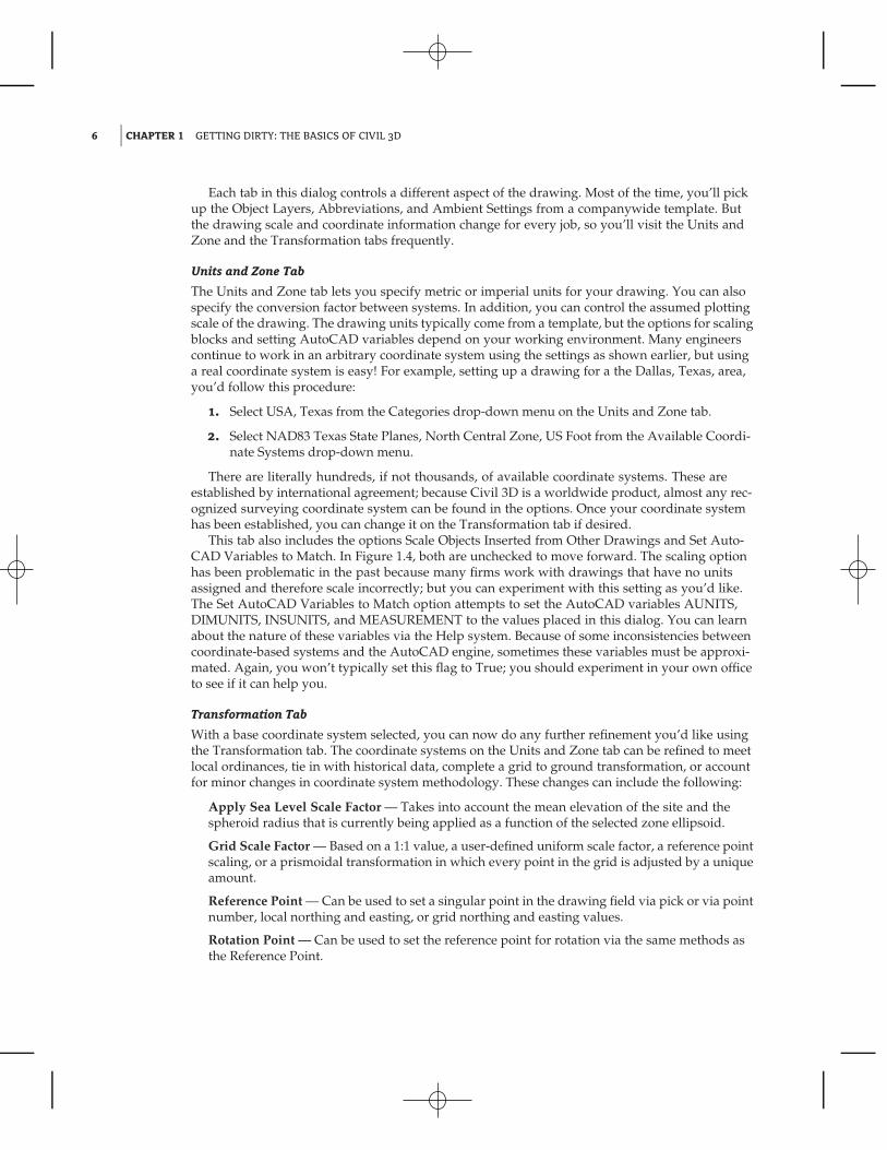
Each tab in this dialog controls a different aspect of the drawing. Most of the time, you’ll pickup the Object Layers, Abbreviations, and Ambient Settings from a companywide template. Butthe drawing scale and coordinate information change for every job, so you’ll visit the Units andZone and the Transformation tabs frequently.
Units and Zone Tab
The Units and Zone tab lets you specify metric or imperial units for your drawing. You can alsospecify the conversion factor between systems. In addition, you can control the assumed plottingscale of the drawing. The drawing units typically come from a template, but the options for scalingblocks and setting AutoCAD variables depend on your working environment. Many engineerscontinue to work in an arbitrary coordinate system using the settings as shown earlier, but usinga real coordinate system is easy! For example, setting up a drawing for a the Dallas, Texas, area,you’d follow this procedure:
1. Select USA, Texas from the Categories drop-down menu on the Units and Zone tab.
2. Select NAD83 Texas State Planes, North Central Zone, US Foot from the Available Coordi-nate Systems drop-down menu.
There are literally hundreds, if not thousands, of available coordinate systems. These areestablished by international agreement; because Civil 3D is a worldwide product, almost any rec-ognized surveying coordinate system can be found in the options. Once your coordinate systemhas been established, you can change it on the Transformation tab if desired.
This tab also includes the options Scale Objects Inserted from Other Drawings and Set Auto-CAD Variables to Match. In Figure 1.4, both are unchecked to move forward. The scaling optionhas been problematic in the past because many firms work with drawings that have no unitsassigned and therefore scale incorrectly; but you can experiment with this setting as you’d like.The Set AutoCAD Variables to Match option attempts to set the AutoCAD variables AUNITS,DIMUNITS, INSUNITS, and MEASUREMENT to the values placed in this dialog. You can learnabout the nature of these variables via the Help system. Because of some inconsistencies betweencoordinate-based systems and the AutoCAD engine, sometimes these variables must be approxi-mated. Again, you won’t typically set this flag to True; you should experiment in your own officeto see if it can help you.
Transformation Tab
With a base coordinate system selected, you can now do any further refinement you’d like usingthe Transformation tab. The coordinate systems on the Units and Zone tab can be refined to meetlocal ordinances, tie in with historical data, complete a grid to ground transformation, or accountfor minor changes in coordinate system methodology. These changes can include the following:
Apply Sea Level Scale Factor — Takes into account the mean elevation of the site and thespheroid radius that is currently being applied as a function of the selected zone ellipsoid.
Grid Scale Factor — Based on a 1:1 value, a user-defined uniform scale factor, a reference pointscaling, or a prismoidal transformation in which every point in the grid is adjusted by a uniqueamount.
Reference Point — Can be used to set a singular point in the drawing field via pick or via pointnumber, local northing and easting, or grid northing and easting values.
Rotation Point — Can be used to set the reference point for rotation via the same methods asthe Reference Point.

WINDOWS ON THE MODEL 7
Specify Grid Rotation Angle — Enter an amount or set a line to North by picking an angle ordeflection in the drawing. You can use this same method to set the azimuth if desired.
Most engineering firms work on either a defined coordinate system or an arbitrary system, sonone of these changes are necessary. Given that, this tab will be your only method of achieving thenecessary transformation for certain surveying and Geographic Information System (GIS)–based,and Land Surveying–based tasks.
Object Layers Tab
Setting object layers to your company standard is a major part of creating the feel you’re afterwhen using Civil 3D in your office. The nearly 50 objects described here make up the entirety ofthe Civil 3D modeling components and the objects you and other users will deal with daily.
The layers listed in this dialog by default reflect a modified AIA CAD Layer Guideline aspart of the National CAD Standard (NCS). This layering standard is built into many places inCivil 3D’s templates and is becoming more widely adopted in the land-development industry.In addition to being fairly comprehensive and well known among engineering firms, theNCS has the benefit of being the roadmap for the future in terms of out-of-the-box contentfrom Autodesk. Adopting this standard means you’ll have fewer things to change with everyrelease of the software. Nevertheless, it is important that every user know how to modify thesedefaults.
One common issue with the shipping templates is that the templates assume road design is theprimary use of alignments. Use the following procedure to change the Alignment setting to theNCS for laying out a sanitary sewer:
1. Click the Layer column in the Alignment row, as shown in Figure 1.5.
Figure 1.5
Changing the Layersetting for the Align-ment object
2. In the Layer Selection dialog list, select C-SSWR-CNTR and click OK.

8 CHAPTER 1 GETTING DIRTY: THE BASICS OF CIVIL 3D
One Object at a Time
Note that this procedure only changes the Alignment object. If you want to change the standard of allthe objects, you need to adjust the Alignment Labeling, Alignment Table, Profile, Profile View, ProfileView Labeling, and so on. To do this, it’s a good idea to right-click in the grid view and select Copy All.You can then paste the contents of this matrix into Microsoft Excel for easy formatting and reviewing.
One common question that surrounds the Object Layers tab is the check box at lower left:Immediate and Independent Layer On/Off Control of Display Components. What the heck doesthat mean? Relax — it’s not as complicated as it sounds.
Many objects in Civil 3D are built from underlying components. Take an alignment, forexample. It’s built from tangents, curves, spirals, extension lines, and so on. Each of thesecomponents can be assigned its own layer — in other words, the lines could be assigned tothe LINES layer, curves to the CURVES layer, and so on. When this check box is selected, thecomponent’s layer exerts some control. In the example given, if the alignment is assigned tothe ALIGN layer and the box is selected, turning off (not freezing) the LINES layer will make theline components of that alignment disappear. Deselect this control, and the LINES layer’s statuswon’t have any effect on the visibility of the alignment line components.
Finally, it’s important to note that this layer control determines the object’s parent layer atcreation. Civil 3D objects can be moved to other layers at any time. Changing this setting doesn’tchange any objects already in place in the drawing.
Abbreviations Tab
One could work for years without noticing the Abbreviations tab. The options on this tab allowyou to set the abbreviations Civil 3D uses when labeling items as part of its automated routines.The prebuilt settings are based on user feedback, and many of them are the same as the settingsfrom Land Desktop, the last-generation civil engineering product from Autodesk.
Changing an abbreviation is as simple as clicking in the Value field and typing a new one.Notice that the Alignment Geometry Point Entity Data section has a larger set of values and someformulas attached. These are more representative of other label styles, and we’ll visit the labeleditor a little later in this chapter.
There’s Always More to Learn
Until December 2006, James was still advising users to add ‘‘t.’’ to their labels to get ‘‘Rt.’’ or ‘‘Lt.’’ inthe final label. He’d forgotten that the abbreviations being used were set here! By changing the Leftand Right abbreviation from ‘‘L’’ and ‘‘R’’ to ‘‘Lt.’’ and ‘‘Rt.’’, respectively, you can skip that step inthe label setup. Sometimes there are just too many options to remember them all!
Ambient Settings Tab
The Ambient Settings tab can be daunting at first. The term ambient means ‘‘surround’’ or ‘‘sur-rounding,’’ and these settings control many of the math, labeling, and display features, as well asthe user interaction surrounding the use of Civil 3D. Being familiar with the way this tab workswill help you further down the line, because almost every other setting dialog in the programworks like the one shown in Figure 1.6.

WINDOWS ON THE MODEL 9
Figure 1.6
The Ambient Settingstab with the Generalbranch expanded
You can approach this tab in the following ways:
◆ Top to bottom — Expand one branch, handle the settings in that branch, and then close itand move to the next.
◆ Print and conquer — Expand all the branches using the Expand All Categories button foundat lower right.
After you have expanded the branches, right-click in the middle of the displayed optionsand select Copy to Clipboard. Then paste the settings to Excel for review, as you did withthe Object Layers tab.
Sharing the Workload
The Print and Conquer approach makes it easy to distribute multiple copies to surveyors, land plan-ners, engineers, and so on and let them fill in the changes. Then, creating a template for each groupis a matter of making their changes. If you’re asking end users who aren’t familiar with the productto make these changes, it’s easy to miss one. Working line by line is fairly foolproof.
After you decide how to approach these settings, get to work. The settings are either drop-downmenus or text boxes (in the case of numeric entries). Many of them are self-explanatory and com-mon to land-development design. Let’s look at these settings in more detail (see Figure 1.6).
Plotted Unit Display Type Remember, Civil 3D knows you want to plot at the end of theday. In this case, it’s asking you how you would like your plotted units measured. For example,would you like that bit of text to be 0.25′′ tall or 1
4′′ high? Most engineers are comfortable with
the Leroy method of text heights (L80, L100, L140, and so on), so the decimal option is thedefault.

10 CHAPTER 1 GETTING DIRTY: THE BASICS OF CIVIL 3D
Set AutoCAD Units This displays whether or not Civil 3D should attempt to match Auto-CAD drawing units, as specified on the Units and Zone tab.
Save Command Changes to Settings This setting is incredibly powerful but a secret toalmost everyone. By setting it to Yes, your changes to commands will be remembered from useto use. This means if you make changes to a command during use, the next time you call thatCivil 3D command, you won’t have to make the same changes. It’s frustrating to do work overbecause you forgot to change one out of the five things that needed changing, so this setting isinvaluable.
Show Event Viewer Event Viewer is Civil 3D’s main feedback mechanism, especially whenthings go wrong. It can get annoying, however, and it takes up valuable screen real estate(especially if you’re stuck with one monitor!), so many people turn it off. We recommendleaving it on and pushing it to the side if needed.
Show Tooltips One of the cool features that people remark on when they first use Civil 3Dis the small pop-up that displays relevant design information when the cursor is paused onthe screen. This includes things such as Station-Offset information, Surface Elevation, Sectioninformation, and so on. Once a drawing contains numerous bits of information, this displaycan be overwhelming; therefore, Civil 3D offers the option to turn off these tooltips universallywith this setting. A better approach is to control the tooltips at the object type by editing theindividual feature settings. You can also control the tooltips by pulling up the properties forany individual object and looking at the Information tab.
Imperial to Metric Conversion This displays the conversion method specified on the Unitsand Zone tab. The two options currently available are US Survey Foot and International Foot.
New Entity Tooltip State You can also control tooltips on an individual object level. Forinstance, you might want tooltip feedback on your proposed surface but not on the existingsurface. This setting controls whether the tooltip is turned on at the object level for new Civil3D objects.
Driving Direction Specifies the side of the road that forward-moving vehicles use for travel.This setting is important in terms of curb returns and intersection design.
Drawing Unit, Drawing Scale, and Scale Inserted Objects These settings were specified onthe Units and Zone tab but are displayed here for reference and so that you can lock them ifdesired.
Independent Layer On This is the same control that was set on the Object Layers tab.
The settings that are applied here can also be applied at the object levels. For example, youmay typically want elevation to be shown to two decimal places; but when looking at surfaceelevations, you might want just one. The Override and Child Override columns give you feedbackabout these types of changes. See Figure 1.7.
The Override column shows whether the current setting is overriding something higher up.Because you’re at the Drawing Settings level, these are clear. However, the Child Override columndisplays a down arrow, indicating that one of the objects in the drawing has overridden thissetting. After a little investigation through the objects, you’ll find the override is in the Edit FeatureSettings of the Profile View as shown in Figure 1.8.
Notice that in this dialog, the box is checked in the Override column. This indicates that you’reoverriding the settings mentioned earlier, and it’s a good alert that things have changed from thegeneral Drawing Settings to this Object Level setting.

WINDOWS ON THE MODEL 11
Figure 1.7
The Child Override indi-cator in the Elevationvalues
Figure 1.8
The Profile ElevationSettings and the Over-ride indicator
But what if you don’t want to allow those changes? Each Settings dialog includes one morecolumn: Lock. At any level, you can lock a setting, graying it out for lower levels. This can behandy for keeping users from changing settings at the lower level that perhaps should be changedat a drawing level, such as sign or rounding methods.

12 CHAPTER 1 GETTING DIRTY: THE BASICS OF CIVIL 3D
Object Settings
If you click the Expand button next to the drawing name, you see the full array of objects thatCivil 3D uses to build its design model. Each of these has special features unique to the objectbeing described, but there are some common features as well. Additionally, the General collectioncontains settings and styles that are applied to various objects across the entire product.
The General collection serves as the catchall for styles that apply to multiple objects and forsettings that apply to no objects. For instance, the Civil 3D General Note object doesn’t reallybelong with the Surface or Pipe collections. It can be used to relate information about those objects,but because it can also relate to something like ‘‘Don’t Dig Here!’’ it falls into the general category.The General collection has three components (or branches):
Multipurpose Styles These styles are used in many objects to control the display of compo-nent objects. The Marker Styles and Link Styles collections are typically used in cross-sectionviews, whereas the Feature Line Styles collection is used in grading and other commands.Figure 1.9 shows the full collection of multipurpose styles and some of the marker styles thatship with the product.
Figure 1.9
General multipur-pose styles and somemarker styles
Label Styles The Label Styles collection allows Civil 3D users to place general text notes orlabel single entities outside the parcel network while still taking advantage of Civil 3D’s flex-ibility and scaling properties. With the various label styles shown in Figure 1.10, you can getsome idea of their usage.
Figure 1.10
Line label styles

WINDOWS ON THE MODEL 13
Because building label styles is a critical part of producing plans with Civil 3D, a later sectionof this chapter looks at how to build a new basic label and some of the common componentsthat appear in every label style throughout the product.
Commands Almost every branch in the Settings tree contains a Commands folder. Expandingthis folder, as shown in Figure 1.11, shows you the typical long, unspaced command namesthat refer to the parent object.
Figure 1.11
Surface command set-tings in Toolspace
Survey
The Survey palette is displayed optionally and controls the use of the survey, equipment, andfigure prefix databases. Survey is an essential part of land-development projects. Because of thecomplex nature of this tab, all of Chapter 3, ‘‘Lay of the Land: Survey,’’ is devoted to it.
Toolbox
The Toolbox is a launching point for add-ons and reporting functions. To access the Toolbox, fromthe Home tab in the Ribbon, select Toolspace � Palettes � Toolbox. Out of the box, the Toolboxcontains reports created by Autodesk, but you can expand its functionality to include your ownmacros or reports. The buttons on the top of the Toolbox, shown in Figure 1.12, allow you tocustomize the report settings and add new content.
Figure 1.12
The Toolbox palettewith the Edit ToolboxContent button circled
14 CHAPTER 1 GETTING DIRTY: THE BASICS OF CIVIL 3D
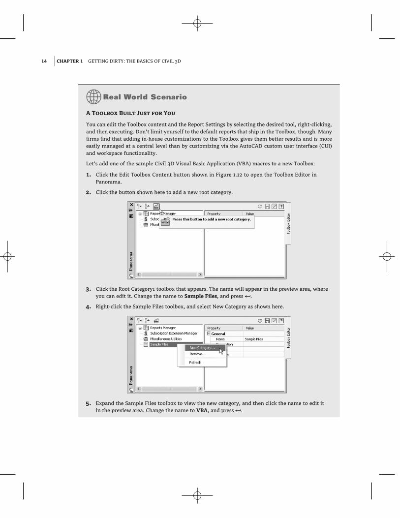
A Toolbox Built Just for You
You can edit the Toolbox content and the Report Settings by selecting the desired tool, right-clicking,and then executing. Don’t limit yourself to the default reports that ship in the Toolbox, though. Manyfirms find that adding in-house customizations to the Toolbox gives them better results and is moreeasily managed at a central level than by customizing via the AutoCAD custom user interface (CUI)and workspace functionality.
Let’s add one of the sample Civil 3D Visual Basic Application (VBA) macros to a new Toolbox:
1. Click the Edit Toolbox Content button shown in Figure 1.12 to open the Toolbox Editor inPanorama.
2. Click the button shown here to add a new root category.
3. Click the Root Category1 toolbox that appears. The name will appear in the preview area, whereyou can edit it. Change the name to Sample Files, and press 5.
4. Right-click the Sample Files toolbox, and select New Category as shown here.
5. Expand the Sample Files toolbox to view the new category, and then click the name to edit itin the preview area. Change the name to VBA, and press 5.

WINDOWS ON THE MODEL 15
6. Right-click the VBA category, and select New Tool.
7. Expand the VBA category to view the new tool, and then click the name to edit it in the previewarea. Change its name to Pipe Sample.
8. Change the Description to Sample VBA.
9. Working down through the properties in the preview area, select VBA in the drop-down menuin the Execute Type field.
10. Click in the Execute File field, and then click the More button.
11. Browse to C:\Program Files\Autocad Civil 3D 2010\Sample\Civil 3D API\COM\Vba\Pipe\,and select the file PipeSample.dvb.
12. Click Open.
13. Click in the Macro Name text field, and type PipeSample as shown here.
14. Click the green check box at upper right to dismiss the editor.
15. You will be asked ‘‘Would you like to apply those changes now?’’ Select Yes.
You’ve now added that sample VBA macro to your Toolbox. By adding commonly used macros andcustom reports to your Toolbox, you can keep them handy without modifying the rest of your Civil3D interface or programming buttons. It’s just one more way to create an interface and toolset for theway you work.
PanoramaThe Panorama window is Civil 3D’s feedback and tabular editing mechanism. Designed to bea common interface for a number of different Civil 3D–related tasks, you can use it to provideinformation about the creation of profile views, to edit pipe or structure information, or to runbasic volume analysis between two surfaces. For an example of Panorama in action, change to theView tab, and then select Palettes � Event Viewer. You’ll explore and use Panorama more duringthis book’s discussion of specific objects and tasks.

16 CHAPTER 1 GETTING DIRTY: THE BASICS OF CIVIL 3D
Running Out of Screen Real Estate?
It’s a good idea to turn on Panorama using this technique and then drag it to the side so you alwayssee any new information. Although it’s possible to turn it off, doing so isn’t recommended — youwon’t know when Civil 3D is trying to tell you something! Place Panorama on your second monitor(now you see why you need to have a second monitor, don’t you?), and you’ll always be up to datewith your Civil 3D model.
And in case you missed it, you were using Panorama when you added the sample VBA macro in theprevious exercise.
RibbonAs with AutoCAD, the Ribbon is the primary interface for accessing Civil 3D commands and fea-tures. When you select an AutoCAD Civil 3D object, the Ribbon displays commands and featuresrelated to that object. If several object types are selected, the Multiple contextual tab is displayed.Use the following procedure to familiarize yourself with the Ribbon:
1. Select one of the line labels in the northwest portion of the Sample Site drawing.
2. Notice that both the General Tools and Modify tabs are displayed as shown in Figure 1.13.
Figure 1.13
The context-sensitiveRibbon
3. Select a parcel label (the labels in the middle of the lot areas) and notice the display of theMultiple contextual tab.
4. Use the Esc key to cancel all selections.
5. Navigate to the Prospector and expand the Alignments� Centerline Alignments collection.
6. Select the Avery Drive alignment, right-click, and choose the Select option on the menu.Notice the change in the Ribbon.

IT’S ALL ABOUT STYLE 17
7. Select the down arrow next to the Modify panel. Using the pin at the bottom-left corner ofthe panel, pin the panel open.
8. Select the Properties command in the General Tools panel to open the AutoCAD Propertiespalette. Notice that the Modify panel remains opened and pinned.
It’s All About StyleBefore you get into the program itself, it’s important to understand one bit of vocabulary and howit relates to Civil 3D: style. To put it simply, styles control the display properties of Civil 3D objectsand labels. Styles control everything from the color of your point markers to the interval of yoursurface contours, and from your profile-view grid spacing to the text height in the Station-Offsetlabel of your road alignment. Styles truly are where the power lies in Civil 3D. Label styles andobject styles are the two major categories.
The difficult thing about styles is that it’s hard to talk about them without being specific. Laterchapters spend a fair amount of time talking about the specifics of the styles for each object, andthis chapter looks at the common aspects of style manipulation; but styles may remain a mysteryuntil you get your hands dirty later in the book.
Label StylesTo get started, look at the styles in the Spot Elevation branch by expanding the Surface branch andthen the Label Styles branch on the Settings tab, as shown in Figure 1.14.
Figure 1.14
Spot Elevation labelstyles
There are two basic label styles in the Spot Elevation branch. Let’s create a new one andexplore the options for making labels. Remember, almost all of these options are present in other,object-specific label styles.
1. Right-click the Spot Elevation folder, and select New in the pop-up menu to open the LabelStyle Composer, as shown in Figure 1.15.
2. On the Information tab, change the style name to something appropriate. For this example,use JW-EG.

18 CHAPTER 1 GETTING DIRTY: THE BASICS OF CIVIL 3D
Figure 1.15
The Label StyleComposer
Who Built That Style?
It’s a good idea to always put something in the style name to indicate it wasn’t in the box. Puttingyour initials or firm name at the beginning of the style is one way to make it easy to differenti-ate your styles from the prebuilt ones. Here, JW stands for James Wedding (EG stands for ExistingGround).
3. Switch to the General tab. Change the layer to C-TOPO-TEXT by clicking the layer cell andthen the More button to the right of that cell.
There are a fair number of options here, so let’s pause the exercise, and look at them fur-ther:
Text Style is the default style for text components that are created on the Layout tab. It’sa good practice to use a zero-height text style with the appropriate font, because you’llset the plotted heights in the style anyway.
Layer is the layer on which the components of a label are inserted, not the layer on whichthe label itself is inserted. Think of labels as nested blocks. The label (the block) getsinserted on the layer on the basis of the object layers you saw earlier. The componentsof the label get inserted on the layer that is set here. This means a change to the specifiedlayer can control or change the appearance of the components if you like.
Orientation Reference sets an object to act as the up direction in terms of readability.Civil 3D understands viewpoint rotation and offers the option to rotate or flip labels tokeep them plan-readable. Most users set this to View to maintain the most plan-readablelabels with the smallest amount of editing later.

IT’S ALL ABOUT STYLE 19
Forced Insertion makes more sense in other objects and will be explored further. Thisfeature essentially allows you to dictate the insertion point of a label on the basis of theobject being labeled.
Plan Readable text maintains the up direction in spite of view rotation. This tends tobe the ‘‘Ooooh, nice’’ feature that makes users smile. Rotating 100 labels is a tedious,thankless task, and this option handles it with one click.
Readability Bias is the angle at which readability kicks in. This angle is measured fromthe 0 degree of the x-axis that is common to AutoCAD angle measurements. Whena piece of text goes past the readable bias angle, the text spins to maintain verticalorientation, as shown in Figure 1.16. Note how the label on the far left has rotatedto accommodate the rotation past 110 degrees, the default bias angle. If you set thereadability bias to 90.01, which is a typical setting, the text flips at a near-vertical angle.
Figure 1.16
Examples ofplan-readable text
Flip Anchors with Text determines how the text flips. Most users find that setting thisto False gives the best results, but sometimes flipping an anchor point positions text asneeded. You’ll learn more about anchor points on the Layout tab.
4. Switch to the Layout tab. Again, a lot is going on here, so you’ll work through the optionsand then make changes. As shown in Figure 1.17, each component of the label has a hostof options. On the right is a preview of the label you’re creating or editing. You can pan orzoom this view as needed to give you a better feel for the label style’s appearance as youmake changes.
A Full Three-Dimensional Label Preview?
This preview defaults to a 3D Orbit control. Don’t ask why; we’re as confused as you are. Inevitably,you’ll rotate the view out of a plan-top view, making the plan harder to understand. When this hap-pens, right-click and select Preset Views 5 Top to reorient yourself, or use the Viewcube function topull to the top.

20 CHAPTER 1 GETTING DIRTY: THE BASICS OF CIVIL 3D
Figure 1.17
Options for the labelcomponents
Again, pause and review some of the other options on this tab. Labels are made of indi-vidual components. A component can be text, a block, or a line, and the top row of buttonscontrols the selection, creation, and deletion of these components:
The Component drop-down menu activates which component is being modified in theoptions below. These components are listed in the order in which they were created.
The Create Text Component button lets you create new components. These componentscan be Text, Lines, Blocks, Reference Text, or Ticks. Some options aren’t available forevery label style.
The ability to label one object while referencing another (reference text) is one of themost powerful labeling features of Civil 3D. This is what allows you to label a spot ele-vation for both an existing and a proposed surface at the same time, using the samelabel. Alignments, COGO points, parcels, profiles, and surfaces can all be used as ref-erence text.
The Copy Component button does just that. It copies the component currently selectedin the Component drop-down menu.
The Delete Component button deletes components. Elements that act as the basis forother components can’t be deleted.
The Component Draw Order button lets you shuffle components up and down withinthe label. This feature is especially important when you’re using masks or borders aspart of the label.
You can work your way down the component properties and adjust them as needed fora label:
Name is self-explanatory. It’s the name used in the Component drop-down menuand when selecting other components. When you’re building complicated labels, alittle name description goes a long way.
IT’S ALL ABOUT STYLE 21
Visibility set to True means this component shows on screen. Invisible componentscan be invaluable when you’re creating complicated labels, as you’ll see in laterchapters.
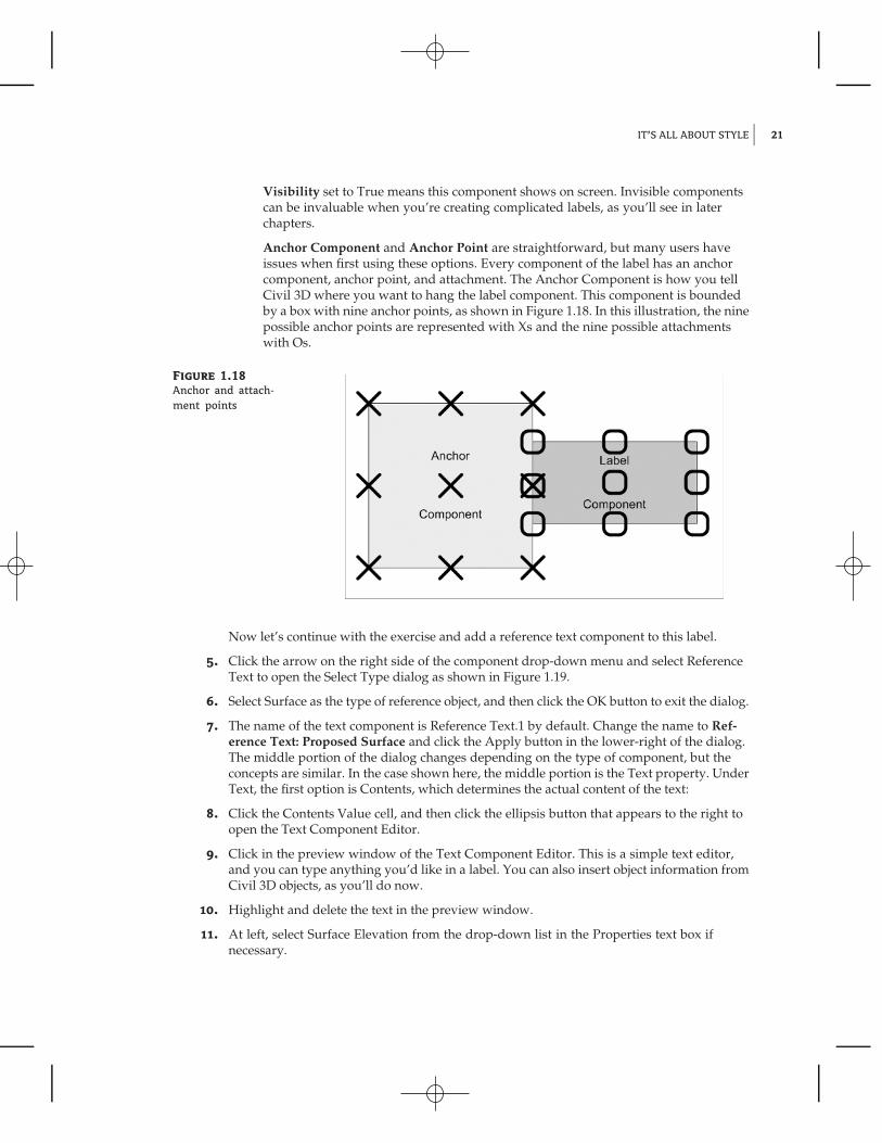
Anchor Component and Anchor Point are straightforward, but many users haveissues when first using these options. Every component of the label has an anchorcomponent, anchor point, and attachment. The Anchor Component is how you tellCivil 3D where you want to hang the label component. This component is boundedby a box with nine anchor points, as shown in Figure 1.18. In this illustration, the ninepossible anchor points are represented with Xs and the nine possible attachmentswith Os.
Figure 1.18
Anchor and attach-ment points
Now let’s continue with the exercise and add a reference text component to this label.
5. Click the arrow on the right side of the component drop-down menu and select ReferenceText to open the Select Type dialog as shown in Figure 1.19.
6. Select Surface as the type of reference object, and then click the OK button to exit the dialog.
7. The name of the text component is Reference Text.1 by default. Change the name to Ref-erence Text: Proposed Surface and click the Apply button in the lower-right of the dialog.The middle portion of the dialog changes depending on the type of component, but theconcepts are similar. In the case shown here, the middle portion is the Text property. UnderText, the first option is Contents, which determines the actual content of the text:
8. Click the Contents Value cell, and then click the ellipsis button that appears to the right toopen the Text Component Editor.
9. Click in the preview window of the Text Component Editor. This is a simple text editor,and you can type anything you’d like in a label. You can also insert object information fromCivil 3D objects, as you’ll do now.
10. Highlight and delete the text in the preview window.
11. At left, select Surface Elevation from the drop-down list in the Properties text box ifnecessary.

22 CHAPTER 1 GETTING DIRTY: THE BASICS OF CIVIL 3D
Figure 1.19
Reference text objectselection
12. Change the precision to one decimal place by clicking in the column next to Precision andselecting 0.1, as shown in Figure 1.20.
Figure 1.20
Setting label precision
13. Click the arrow circled in Figure 1.21 to insert your label text and elevation code into thepreview area.
14. Click OK to exit this dialog, and you’ll be back at the Label Style Composer.
15. Your label is complete. You can click OK to exit, but you might want to leave the label openas we discuss the Dragged State and Summary tabs next.

IT’S ALL ABOUT STYLE 23
Figure 1.21
Don’t forget the arrow!
How Many Dialogs Is That?
You can see why many Civil 3D instructors refer to label creation as ‘‘heading down the rabbithole.’’ You’re a couple of dialogs deep just making the simplest of label styles, with one statictext component. It’s easy to get confused, but don’t worry — it becomes second nature! The TextComponent Editor is another common dialog that appears in every label-style creation exercise.
Let’s look at the rest of the options, even though you won’t be making any changes:
Text Height determines the plotted height of the label. Remember, Civil 3D knows you’regoing to print and will attempt to give you inches or millimeters.
Rotation Angle, X Offset, and Y Offset give you the ability to refine the placement of this com-ponent by rotating or displacing the text in an x or y direction.
Attachment determines which of the nine points on the label components bounding box areattached to the anchor point. See Figure 1.18 for an illustration. Change the attachment of thereference text component to Top Left. This will attach the upper-left corner of this proposedelevation reference text to the bottom left of the Surface Elevation component.
Color and Lineweight allow you to hard-code a color if desired. It’s a good idea to leave thesevalues set to ByLayer unless you have a good reason to change them.
The final piece of the component puzzle is a Border option. These options are as follows:
Visibility is obvious, turning the border on and off for this component. Remember that com-ponent borders shrink to the individual component: if you’re using multiple components in alabel, they all have their own borders.
Type allows you to select a rectangle, a rounded rectangle (slot), or a circle border.
Background Mask lets you determine whether linework and text behind this component aremasked. This can be handy for construction notes in place of the usual wipeout tools.
Gap determines the offset from the component bounding box to the outer points on the border.Setting this to half of the text size usually creates a visually pleasing border.
Linetype and Lineweight give you the usual control of the border lines.

24 CHAPTER 1 GETTING DIRTY: THE BASICS OF CIVIL 3D
After working through all the options for the default label placement, you need to set theoptions that come into play when a label is dragged. Switch to the Dragged State tab. When a labelis dragged in Civil 3D, it typically creates a leader, and text rearranges. The settings that controlthese two actions are on this tab. Unique options are explained here:
Arrow Head Style and Size control the tip of the leader. Note that Arrow Head Size also con-trols the tail size leading to the text object.
Type controls the leader type. Options are Straight Leader and Spline Leader. At the time ofthis writing, the AutoCAD multiple leader object can’t be used.
Display controls whether components rearrange their placement to a stacked set of compo-nents (Stacked Text) or maintain their arrangement as originally composed (As Composed).Most users expect this to be set to As Composed for the most predictable behavior.
Every label has a Summary tab, and clicking the Expand All button circled in Figure 1.22 willpresent you with a full array of details about the label. Working down the Summary tab, youcan review all of the options that have been selected for an individual label, as well as look foroverrides, just like you did on the Settings tab. Click OK to exit the dialog; your new style willappear on the Settings tab.
Figure 1.22
Summary tab withthe Expand All buttoncircled
The purpose of this exercise wasn’t to build a Surface Spot Elevation label style; it was tofamiliarize you with the common elements of creating a label: the Label Style Composer andthe Text Component Editor. However, you can try out the new label to check your work!
Object StylesBeyond the styles used to label objects, Civil 3D also depends on styles to control the display ofthe native objects, including points, surface, alignments, and so on. Just as in label styles, certain
IT’S ALL ABOUT STYLE 25
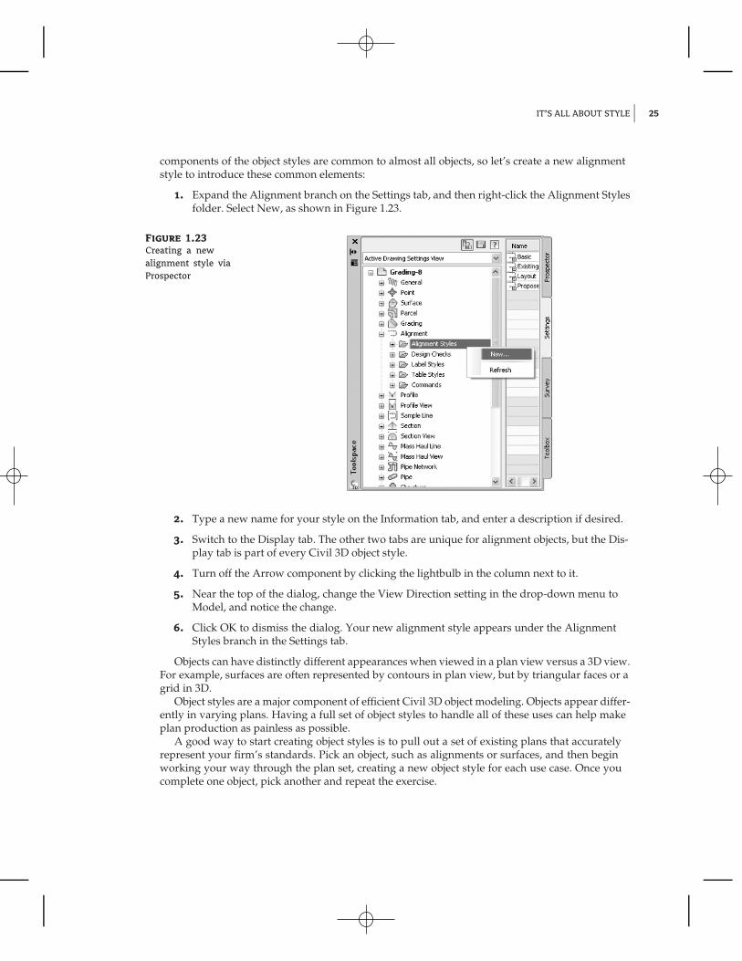
components of the object styles are common to almost all objects, so let’s create a new alignmentstyle to introduce these common elements:
1. Expand the Alignment branch on the Settings tab, and then right-click the Alignment Stylesfolder. Select New, as shown in Figure 1.23.
Figure 1.23
Creating a newalignment style viaProspector
2. Type a new name for your style on the Information tab, and enter a description if desired.
3. Switch to the Display tab. The other two tabs are unique for alignment objects, but the Dis-play tab is part of every Civil 3D object style.
4. Turn off the Arrow component by clicking the lightbulb in the column next to it.
5. Near the top of the dialog, change the View Direction setting in the drop-down menu toModel, and notice the change.
6. Click OK to dismiss the dialog. Your new alignment style appears under the AlignmentStyles branch in the Settings tab.
Objects can have distinctly different appearances when viewed in a plan view versus a 3D view.For example, surfaces are often represented by contours in plan view, but by triangular faces or agrid in 3D.
Object styles are a major component of efficient Civil 3D object modeling. Objects appear differ-ently in varying plans. Having a full set of object styles to handle all of these uses can help makeplan production as painless as possible.
A good way to start creating object styles is to pull out a set of existing plans that accuratelyrepresent your firm’s standards. Pick an object, such as alignments or surfaces, and then beginworking your way through the plan set, creating a new object style for each use case. Once youcomplete one object, pick another and repeat the exercise.

26 CHAPTER 1 GETTING DIRTY: THE BASICS OF CIVIL 3D
The Underlying EngineCivil 3D is part of a larger product family from Autodesk. During its earliest creation, variousfeatures and functions from other products were recognized as important to the civil engineer-ing community. These included the obvious things such as the entire suite of AutoCAD drafting,design, modeling, and rendering tools as well as more esoteric options such as Map’s GIS capabil-ities. An early decision was made to build Civil 3D on top of the AutoCAD Map product, whichin turn is built on top of AutoCAD.
This underlying engine provides a host of options and powerful tools for the Civil 3D user.AutoCAD and Map add features with every release that change the fundamental makeup of howCivil 3D works. With the introduction of workspaces in 2006, users can now set up Civil 3D todisplay various tools and palettes depending on the task at hand. Creating a workspace is likehaving a quick-fix bag of tools ready for the job at hand: preliminary design calls for one set oftools, and final plan production calls for another.
Workspaces are part of a larger feature set called the custom user interface (referred to as CUI inthe help documentation and online). As you grow familiar with Civil 3D and the various toolpalettes, menus, and toolbars, be sure to explore the CUI options that are available from theWorkspace toolbar.
The Bottom LineFind any Civil 3D object with just a few clicks. By using Prospector to view object datacollections, you can minimize the panning and zooming that are part of working in a CADprogram. When common subdivisions can have hundreds of parcels or a complex corridorcan have dozens of alignments, jumping to the desired one nearly instantly shaves time offeveryday tasks.
Master It Open Sample Site.dwg from the tutorials, and find parcel number five withoutusing any AutoCAD commands.
Modify the drawing scale and default object layers. Civil 3D understands that the end goalof most drawings is to create hard-copy construction documents. By setting a drawing scaleand then setting many sizes in terms of plotted inches or millimeters, Civil 3D removes muchof the mental gymnastics that other programs require when you’re sizing text and symbols. Bysetting object layers at a drawing scale, Civil 3D makes uniformity of drawing files easier thanever to accomplish.
Master It Change Sample Site.dwg from a 200-scale drawing to a 40-scale drawing.
Modify the display of Civil 3D tooltips. The interactive display of object tooltips makes iteasy to keep your focus on the drawing instead of an inquiry or report tools. When too manyobjects fill up a drawing, it can be information overload, so Civil 3D gives you granular controlover the heads-up display tooltips.
Master It Within the same Sample Site drawing, turn off the tooltips for the Avery Drivealignment.
Add a new tool to the Toolbox. The Toolbox provides a convenient way to access macrosand reports. Many third-party developers exploit this convenient interface as an easier way toadd functionality without disturbing users’ workspaces.
Master It Add the Sample Pipe macro from C:\Program Files\Autocad Civil 3D2010\Sample\Civil 3D API\COM\Vba\Pipe, and select PipeSample.dvb.

THE BOTTOM LINE 27
Create a basic label style. Label styles determine the appearance of Civil 3D annotation. Thecreation of label styles will constitute a major part of the effort in making the transition to Civil3D as a primary platform for plan production. Your skills will grow with the job requirementsif you start with basic labels and then make more complicated labels as needed.
Master It Create a copy of the Elevation Only Point label style, name it Elevation WithBorder, and add a border to the text component.
Create a new object style. Object styles in Civil 3D let you quit managing display throughlayer modification and move to a more streamlined style-based control. Creating enough objectstyles to meet the demands of plan production work will be your other major task in preparingto move to Civil 3D.
Master It Create a new Surface style named Contours_Grid, and set it to show contours inplan views but a grid display in any 3D view.
Navigate the Ribbon’s contextual tabs. As with AutoCAD, the Ribbon is the primary inter-face for accessing Civil 3D commands and features. When you select an AutoCAD Civil 3Dobject, the Ribbon displays commands and features related to that object. If several object typesare selected, the Multiple contextual tab is displayed.
Master It Using the Ribbon interface, access the Alignment Style Editor for the ProposedAlignment style. (Hint: it’s used by the Avery Drive alignment.)
