geothermal well cementing, materials and placement techniques · geothermal training programme...
TRANSCRIPT
GEOTHERMAL TRAINING PROGRAMME Reports 2010 Orkustofnun, Grensásvegur 9, Number 10 IS-108 Reykjavík, Iceland
99
GEOTHERMAL WELL CEMENTING, MATERIALS AND PLACEMENT TECHNIQUES
Evans Kiprotich Bett Kenya Electricity Generating Company Ltd.
Geothermal Resource Development P.O. Box 785, 20117 Naivasha
KENYA [email protected]
ABSTRACT
Geothermal wells are cemented using many of the same techniques as in the oil and gas industry. However, high temperatures, corrosive brines and carbon dioxide severely challenge the long-term durability of well cements. Well cementing is a critical part of well construction and requires a dedicated design and engineering process. Portland cement manufactured to API specifications, classes A and G, is most commonly utilised in geothermal wells cementing. The cements and cement additives selected and the cementing practices utilised are an integral part of sound well design, construction and well integrity. Selected cements, additives and mixing fluids should be laboratory tested in advance to ensure they meet the requirements of the well design. Silica flour is included in the design of cement slurry to prevent strength retrogression that occurs as a result of elevated temperatures encountered in geothermal wells. Proper well conditioning before cementing ensures a sound cement sheath. There are four common techniques utilised in the primary cementing of geothermal wells. There are other techniques used to execute remedial cementing jobs when the need arises. During cementing operations, various parameters are recorded as part of the monitoring of the cementing execution job and for post-job analyses. In the post-job evaluation, it is important to carry out acoustic logs.
1. INTRODUCTION Cementing is the process of mixing and pumping cement slurry down to fill the annular space behind the pipe. When setting, the cement will establish a bond between the pipe and the formation. Unlike oil and gas wells, the casings in geothermal wells are usually fully cemented back to the surface. Portland cement is the most commonly used cement. The American Petroleum Institute (API) classifies cement into eight types depending on required properties. Slurry is made by mixing cement with water and additives. Chemical additives are mixed into the cement slurry to alter the properties of both the slurry and the hardened cement. The success and long life of well cementation requires the utilization of high-grade steel casing strings with special threaded couplings and temperature-stabilized cementing compositions. A hydraulic seal
Bett 100 Report 10
must be established between the cement and the casing and between the cement and the formation. This requirement makes the primary cementing operation important for the performance of the well. Geothermal wells are drilled in areas with hot water or steam and because of the hostile conditions, special planning is necessary to ensure the integrity of the well. When primary cementing is not well executed due to poor planning, despite using the right methods and materials, remedial cementing may have to be done in order to restore a well’s operation. In general, there are five steps in designing a successful cement placement:
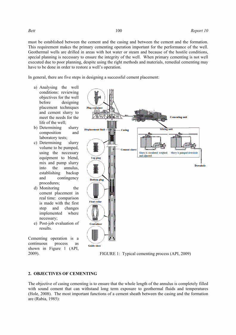
a) Analysing the well conditions: reviewing objectives for the well before designing placement techniques and cement slurry to meet the needs for the life of the well;
b) Determining slurry composition and laboratory tests;
c) Determining slurry volume to be pumped, using the necessary equipment to blend, mix and pump slurry into the annulus, establishing backup and contingency procedures;
d) Monitoring the cement placement in real time: comparison is made with the first step and changes implemented where necessary;
e) Post-job evaluation of results.
Cementing operation is a continuous process as shown in Figure 1 (API, 2009). 2. OBJECTIVES OF CEMENTING The objective of casing cementing is to ensure that the whole length of the annulus is completely filled with sound cement that can withstand long term exposure to geothermal fluids and temperatures (Hole, 2008). The most important functions of a cement sheath between the casing and the formation are (Rabia, 1985):
FIGURE 1: Typical cementing process (API, 2009)
Report 10 101 Bett
a) To prevent the movement (migration) of fluids from one formation to another or from the formations to the surface through the annulus;
b) To hold the casing string in the well; c) To protect the casing from corrosive fluids in the formations and buckling; d) To support the well-bore walls (in conjunction with the casing) to prevent collapse of
formations; e) To prevent blowouts by forming a seal in the annulus; f) To protect the casing from shock loads when drilling deeper.
Cementing is also used to condition the well:
a) To seal loss of circulation zones; b) To stabilize weak zones (washouts, collapses); c) To plug a well for abandonment or for repair; d) To kick-off side tracking in an open hole or past a junk; e) To plug a well temporarily before being re-cased.
3. WELL CONDITIONS It is important to get a clear picture of the conditions in the well to identify loss zones, losses, temperature, wellbore enlargements and other potentially useful information. 3.1 Mud conditioning The top priority in achieving a successful cement job is to displace all the mud from the annular section to be cemented and the mud cake on the annular wall. Drilling mud is designed to help efficiently drill, transport cuttings to the surface and form a mud cake, but is not always conducive to good mud displacement during cementing operations. Therefore, prior to running the casing and cementing, the drilling fluid should be conditioned to exhibit ‘easy-to-remove’ properties including low fluid loss, thin rheological properties, and a flat gel profile (Bush and O'Donnell, 2007). Reducing the mud’s gel strength, yield stress and plastic viscosity is recognized as being beneficial, because the driving forces necessary to displace the mud are reduced, and its mobility is increased (Nelson, 1990). The addition of mud thinners and deflocculants will aid in this process. Prior to logging operations or the installation of casing, the bit should be short tripped to the previous casing shoe and then run back to bottom to be certain the well will remain open. Additionally, if there is a concern for mud losses while running casing or cementing, LCM (Lost Circulation Material) pill should be spotted on the bottom prior to POOH (Pull Out Of Hole) with the drill string. Once the casing has been run, the mud should be further conditioned to remove gelled mud which will have formed beneath the casing in areas of poor centralization. After landing the casing, and the drilling mud has been conditioned, the cementing should begin as soon as possible, preferably within 15 minutes. Increased static times may cause the mud to gel significantly and make it difficult to remove from the annulus (Bush and O'Donnell, 2007). 3.2 Casing movement If possible, the casing should be reciprocated. The pipe movement will both physically scrape mud from the wellbore, as well as keep fluid moving around all portions of the hole. Reciprocation is 5-15 m stroke length at 1 stroke per minute (Bush and O'Donnell, 2007).
Bett 102 Report 10
3.3 Centralization Good centralization is an important factor in achieving efficient mud displacement and cement placement. A poorly drilled hole may have several washed out zones which are difficult to clean out, regardless of the displacement rate. Crooked holes make casing centralization difficult. Consequently, the removal of the mud from the narrow side of the annulus is problematic. It is therefore necessary to ensure that the drilled hole is smooth without doglegs, in-gauge and stable (Nelson, 1990). A minimum casing stand-off of 70% through critical sections is a good rule-of-thumb. Stand-off can range from 0% (casing against the hole wall) to 100% (casing perfectly centred in the hole) (Bush and O'Donnell, 2007). 3.4 Bottomhole temperature Accurate prediction of bottomhole circulation temperature (BHCT) and bottomhole static temperature (BHST) is important during drilling and completion of geothermal wells. The majority of borehole temperature measurements are obtained as maximum-reading values acquired during logging runs. Many methods and algorithms have been proposed to extrapolate bottomhole temperature values, measured during drilling or soon after circulation has ceased, in order to obtain static borehole or formation temperature. To plan the cementing operations in high-temperature geothermal wells, accurate circulation temperatures are required. The BHCT typically used for cement slurry design are found in API Specification 10. It assumes 26°C surface formation temperature. One must know the average static temperature gradient to design cement-slurry thickening time with the current API bottomhole temperature circulation correlations. Many drilling operators have observed that the API method overestimates circulating mud temperatures for deep wells. A recently developed API equivalent well (API-EW) method allows one to use the API temperature correlations for any deep well, both onshore and offshore, and for any values of surface formation temperature. The API-EW method transforms a real wellbore into an API equivalent wellbore by treating the well’s 26°C isotherm as the surface temperature (Kutasov and Kagan, 2002). To calculate the average temperature gradient and determine the rate of cement strength development, BHST has to be known. Bottomhole shut-in temperature is used and an approximate analytical method. It is a function of drilling fluid circulation time, shut-in time, wellbore radius, circulation time, and formation thermal diffusivity. A BHCT memory recorder was recently developed, capable of recording downhole temperatures during circulation before cementing, squeezing or plugback operations. The recorder can be tripped into the well with a pipe or wireline and can be dropped down the drill string. Temperature data obtained with BHCT recorders are representative of true bottomhole circulating temperatures and can provide an accurate assessment of downhole temperature conditions before critical cementing operations are performed (Kabinoff et al., 1992). Because of the uncertainty of actual BHCT, retardation and testing of the cement can be challenging. 3.5 Caliper log A caliper log is used to measure the wellbore diameter. After the casing point is reached, caliper logs should be run, and the cement volume should be adjusted based upon the actual wellbore size. Even with the caliper log, it is common practice to use an excess volume to ensure fill-up by cement across all critical zones. The excess factor used is based on the experience obtained from the field being drilled. The volume obtained is added to the volume of cement that will remain between the float collar and the shoe, i.e. in the shoe track. The most commonly used caliper tools have 4 or more
Report 10 103 Bett
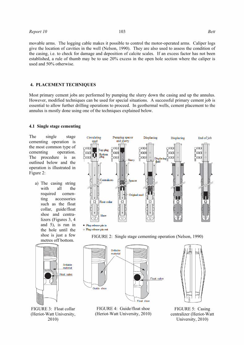
movable arms. The logging cable makes it possible to control the motor-operated arms. Caliper logs give the location of cavities in the well (Nelson, 1990). They are also used to assess the condition of the casing, i.e. to check for damage and deposition of calcite scales. If an excess factor has not been established, a rule of thumb may be to use 20% excess in the open hole section where the caliper is used and 50% otherwise. 4. PLACEMENT TECHNIQUES Most primary cement jobs are performed by pumping the slurry down the casing and up the annulus. However, modified techniques can be used for special situations. A successful primary cement job is essential to allow further drilling operations to proceed. In geothermal wells, cement placement to the annulus is mostly done using one of the techniques explained below. 4.1 Single stage cementing The single stage cementing operation is the most common type of cementing operation. The procedure is as outlined below and the operation is illustrated in Figure 2:
a) The casing string with all the required cemen-ting accessories such as the float collar, guide/float shoe and centra-lizers (Figures 3, 4 and 5), is run in the hole until the shoe is just a few metres off bottom.
FIGURE 2: Single stage cementing operation (Nelson, 1990)
FIGURE 3: Float collar(Heriot-Watt University,
2010)
FIGURE 4: Guide/float shoe (Heriot-Watt University, 2010)
FIGURE 5: Casing centralizer (Heriot-Watt
University, 2010)
Bett 104 Report 10
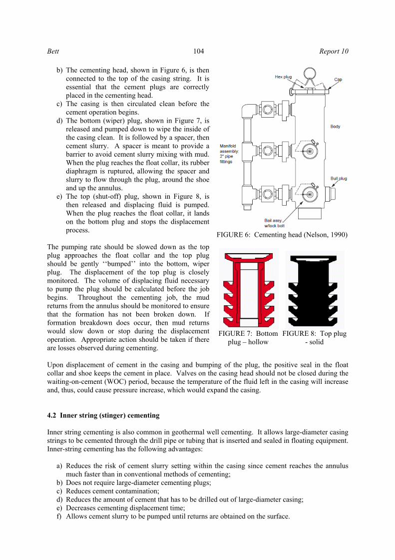
b) The cementing head, shown in Figure 6, is then connected to the top of the casing string. It is essential that the cement plugs are correctly placed in the cementing head.
c) The casing is then circulated clean before the cement operation begins.
d) The bottom (wiper) plug, shown in Figure 7, is released and pumped down to wipe the inside of the casing clean. It is followed by a spacer, then cement slurry. A spacer is meant to provide a barrier to avoid cement slurry mixing with mud. When the plug reaches the float collar, its rubber diaphragm is ruptured, allowing the spacer and slurry to flow through the plug, around the shoe and up the annulus.
e) The top (shut-off) plug, shown in Figure 8, is then released and displacing fluid is pumped. When the plug reaches the float collar, it lands on the bottom plug and stops the displacement process.
The pumping rate should be slowed down as the top plug approaches the float collar and the top plug should be gently ‘‘bumped’’ into the bottom, wiper plug. The displacement of the top plug is closely monitored. The volume of displacing fluid necessary to pump the plug should be calculated before the job begins. Throughout the cementing job, the mud returns from the annulus should be monitored to ensure that the formation has not been broken down. If formation breakdown does occur, then mud returns would slow down or stop during the displacement operation. Appropriate action should be taken if there are losses observed during cementing. Upon displacement of cement in the casing and bumping of the plug, the positive seal in the float collar and shoe keeps the cement in place. Valves on the casing head should not be closed during the waiting-on-cement (WOC) period, because the temperature of the fluid left in the casing will increase and, thus, could cause pressure increase, which would expand the casing. 4.2 Inner string (stinger) cementing Inner string cementing is also common in geothermal well cementing. It allows large-diameter casing strings to be cemented through the drill pipe or tubing that is inserted and sealed in floating equipment. Inner-string cementing has the following advantages:
a) Reduces the risk of cement slurry setting within the casing since cement reaches the annulus much faster than in conventional methods of cementing;
b) Does not require large-diameter cementing plugs; c) Reduces cement contamination; d) Reduces the amount of cement that has to be drilled out of large-diameter casing; e) Decreases cementing displacement time; f) Allows cement slurry to be pumped until returns are obtained on the surface.
FIGURE 6: Cementing head (Nelson, 1990)
FIGURE 7: Bottom plug – hollow
FIGURE 8: Top plug
- solid
Report 10 105 Bett
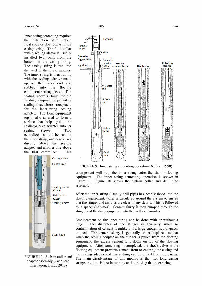
Inner-string cementing requires the installation of a stab-in float shoe or float collar in the casing string. The float collar with a sealing sleeve is usually installed two joints from the bottom in the casing string. The casing string is run into the well in the usual manner. The inner string is then run in, with the sealing adapter made up on the lower end and stabbed into the floating equipment sealing sleeve. The sealing sleeve is built into the floating equipment to provide a sealing-sleeve/bore receptacle for the inner-string sealing adapter. The float equipment top is also tapered to form a surface that helps guide the sealing-sleeve adapter into its sealing sleeve. Two centralizers should be run on the inner string, one centralizer directly above the sealing adapter and another one above the first centralizer. This
arrangement will help the inner string enter the stab-in floating equipment. The inner string cementing operation is shown in Figure 9. Figure 10 shows the stab-in collar and drill pipe assembly. After the inner string (usually drill pipe) has been stabbed into the floating equipment, water is circulated around the system to ensure that the stinger and annulus are clear of any debris. This is followed by a spacer (polymer). Cement slurry is then pumped through the stinger and floating equipment into the wellbore annulus. Displacement on the inner string can be done with or without a plug. The diameter of the stinger is generally small so contamination of cement is unlikely if a large enough liquid spacer is used. The cement slurry is generally under-displaced so that when the sealing adapter on the stinger is pulled from the floating equipment, the excess cement falls down on top of the floating equipment. After cementing is completed, the check valve in the floating equipment prevents cement from re-entering the casing and the sealing adapter and inner string can be pulled from the casing. The main disadvantage of this method is that, for long casing strings, rig time is lost in running and retrieving the inner string.
FIGURE 9: Inner string cementing operation (Nelson, 1990)
FIGURE 10: Stab-in collar and
adapter assembly (CaseTech International, Inc., 2010)
Bett 106 Report 10
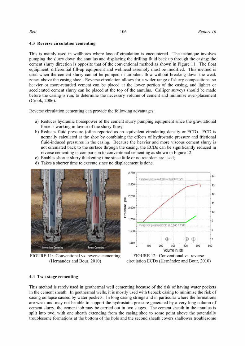
4.3 Reverse circulation cementing This is mainly used in wellbores where loss of circulation is encountered. The technique involves pumping the slurry down the annulus and displacing the drilling fluid back up through the casing; the cement slurry direction is opposite that of the conventional method as shown in Figure 11. The float equipment, differential fill-up equipment and wellhead assembly must be modified. This method is used when the cement slurry cannot be pumped in turbulent flow without breaking down the weak zones above the casing shoe. Reverse circulation allows for a wider range of slurry compositions, so heavier or more-retarded cement can be placed at the lower portion of the casing, and lighter or accelerated cement slurry can be placed at the top of the annulus. Calliper surveys should be made before the casing is run, to determine the necessary volume of cement and minimise over-placement (Crook, 2006). Reverse circulation cementing can provide the following advantages:
a) Reduces hydraulic horsepower of the cement slurry pumping equipment since the gravitational force is working in favour of the slurry flow;
b) Reduces fluid pressure (often reported as an equivalent circulating density or ECD). ECD is normally calculated at the shoe by combining the effects of hydrostatic pressure and frictional fluid-induced pressures in the casing. Because the heavier and more viscous cement slurry is not circulated back to the surface through the casing, the ECDs can be significantly reduced in reverse cementing in comparison to conventional cementing as shown in Figure 12;
c) Enables shorter slurry thickening time since little or no retarders are used; d) Takes a shorter time to execute since no displacement is done.
4.4 Two-stage cementing This method is rarely used in geothermal well cementing because of the risk of having water pockets in the cement sheath. In geothermal wells, it is mostly used with tieback casing to minimise the risk of casing collapse caused by water pockets. In long casing strings and in particular where the formations are weak and may not be able to support the hydrostatic pressure generated by a very long column of cement slurry, the cement job may be carried out in two stages. The cement sheath in the annulus is split into two, with one sheath extending from the casing shoe to some point above the potentially troublesome formations at the bottom of the hole and the second sheath covers shallower troublesome
FIGURE 11: Conventional vs. reverse cementing(Hernández and Bour, 2010)
FIGURE 12: Conventional vs. reverse circulation ECDs (Hernández and Bour, 2010)
Report 10 107 Bett
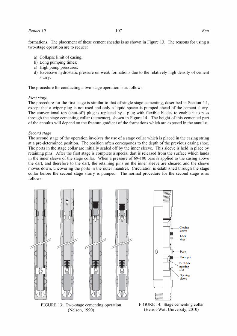
formations. The placement of these cement sheaths is as shown in Figure 13. The reasons for using a two-stage operation are to reduce:
a) Collapse limit of casing; b) Long pumping times; c) High pump pressures; d) Excessive hydrostatic pressure on weak formations due to the relatively high density of cement
slurry. The procedure for conducting a two-stage operation is as follows: First stage The procedure for the first stage is similar to that of single stage cementing, described in Section 4.1, except that a wiper plug is not used and only a liquid spacer is pumped ahead of the cement slurry. The conventional top (shut-off) plug is replaced by a plug with flexible blades to enable it to pass through the stage cementing collar (cementer), shown in Figure 14. The height of this cemented part of the annulus will depend on the fracture gradient of the formations which are exposed in the annulus. Second stage The second stage of the operation involves the use of a stage collar which is placed in the casing string at a pre-determined position. The position often corresponds to the depth of the previous casing shoe. The ports in the stage collar are initially sealed off by the inner sleeve. This sleeve is held in place by retaining pins. After the first stage is complete a special dart is released from the surface which lands in the inner sleeve of the stage collar. When a pressure of 69-100 bars is applied to the casing above the dart, and therefore to the dart, the retaining pins on the inner sleeve are sheared and the sleeve moves down, uncovering the ports in the outer mandrel. Circulation is established through the stage collar before the second stage slurry is pumped. The normal procedure for the second stage is as follows:
FIGURE 13: Two-stage cementing operation (Nelson, 1990)
FIGURE 14: Stage cementing collar
(Heriot-Watt University, 2010)
Bett 108 Report 10
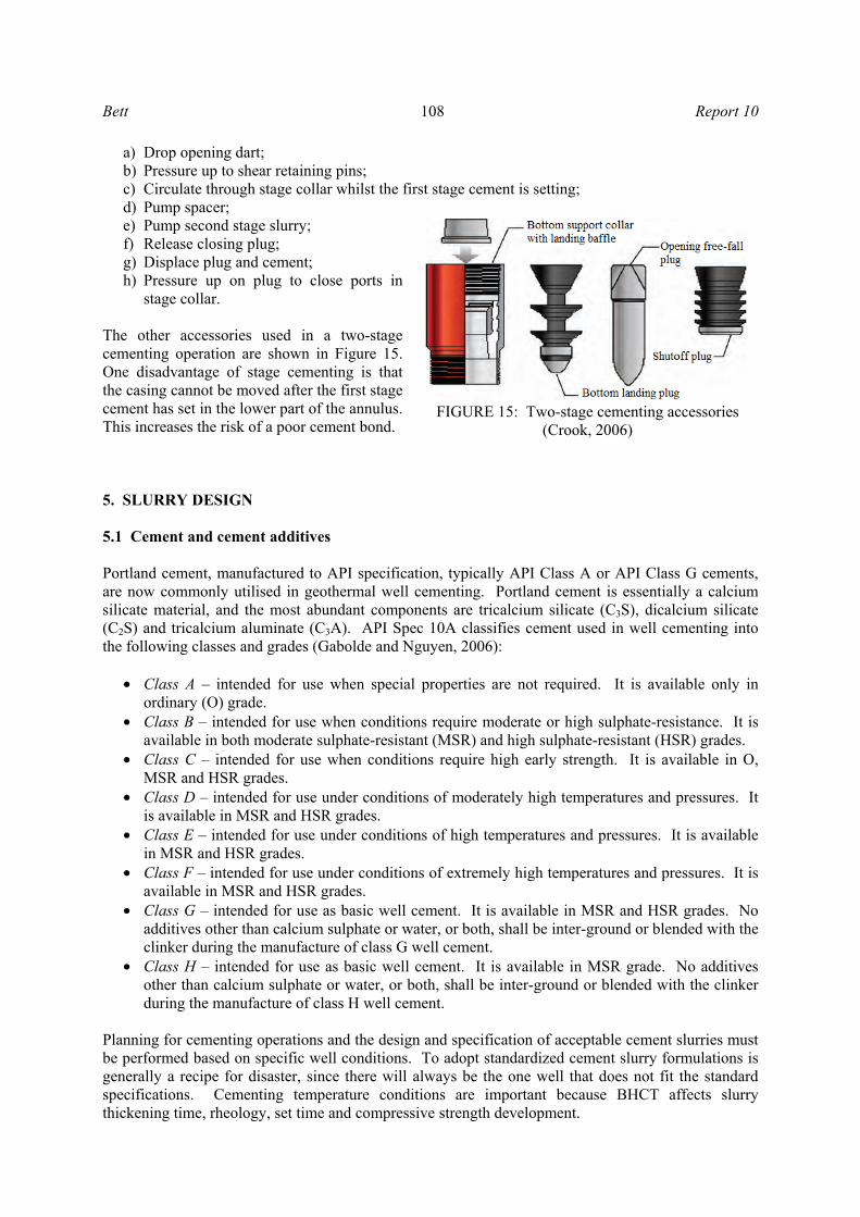
a) Drop opening dart; b) Pressure up to shear retaining pins; c) Circulate through stage collar whilst the first stage cement is setting; d) Pump spacer; e) Pump second stage slurry; f) Release closing plug; g) Displace plug and cement; h) Pressure up on plug to close ports in
stage collar. The other accessories used in a two-stage cementing operation are shown in Figure 15. One disadvantage of stage cementing is that the casing cannot be moved after the first stage cement has set in the lower part of the annulus. This increases the risk of a poor cement bond. 5. SLURRY DESIGN 5.1 Cement and cement additives Portland cement, manufactured to API specification, typically API Class A or API Class G cements, are now commonly utilised in geothermal well cementing. Portland cement is essentially a calcium silicate material, and the most abundant components are tricalcium silicate (C3S), dicalcium silicate (C2S) and tricalcium aluminate (C3A). API Spec 10A classifies cement used in well cementing into the following classes and grades (Gabolde and Nguyen, 2006):
• Class A – intended for use when special properties are not required. It is available only in ordinary (O) grade.
• Class B – intended for use when conditions require moderate or high sulphate-resistance. It is available in both moderate sulphate-resistant (MSR) and high sulphate-resistant (HSR) grades.
• Class C – intended for use when conditions require high early strength. It is available in O, MSR and HSR grades.
• Class D – intended for use under conditions of moderately high temperatures and pressures. It is available in MSR and HSR grades.
• Class E – intended for use under conditions of high temperatures and pressures. It is available in MSR and HSR grades.
• Class F – intended for use under conditions of extremely high temperatures and pressures. It is available in MSR and HSR grades.
• Class G – intended for use as basic well cement. It is available in MSR and HSR grades. No additives other than calcium sulphate or water, or both, shall be inter-ground or blended with the clinker during the manufacture of class G well cement.
• Class H – intended for use as basic well cement. It is available in MSR grade. No additives other than calcium sulphate or water, or both, shall be inter-ground or blended with the clinker during the manufacture of class H well cement.
Planning for cementing operations and the design and specification of acceptable cement slurries must be performed based on specific well conditions. To adopt standardized cement slurry formulations is generally a recipe for disaster, since there will always be the one well that does not fit the standard specifications. Cementing temperature conditions are important because BHCT affects slurry thickening time, rheology, set time and compressive strength development.
FIGURE 15: Two-stage cementing accessories (Crook, 2006)
Report 10 109 Bett
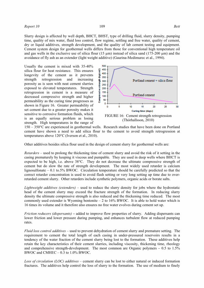
Slurry design is affected by well depth, BHCT, BHST, type of drilling fluid, slurry density, pumping time, quality of mix water, fluid loss control, flow regime, settling and free water, quality of cement, dry or liquid additives, strength development, and the quality of lab cement testing and equipment. Cement system design for geothermal wells differs from those for conventional high temperature oil and gas wells in the exclusive use of silica flour (15 µm) instead of silica sand (175-200 µm) and the avoidance of fly ash as an extender (light weight additive) (Gaurina-Medimurec et al., 1994). Usually the cement is mixed with 35-40% silica flour for heat resistance. This ensures longevity of the cement as it prevents strength retrogression and increasing porosity as is seen with neat cement slurries exposed to elevated temperatures. Strength retrogression in cement is a measure of decreased compressive strength and higher permeability as the curing time progresses as shown in Figure 16. Greater permeability of set cement due to a greater porosity makes it sensitive to corrosive formation fluids, which is an equally serious problem as losing strength. High temperatures in the range of 150 – 350°C are experienced in geothermal wells. Research studies that have been done on Portland cement have shown a need to add silica flour to the cement to avoid strength retrogression at temperatures above 120°C (Iverson et al., 2010). Other additives besides silica flour used in the design of cement slurry for geothermal wells are: Retarders – used to prolong the thickening time of cement slurry and avoid the risk of it setting in the casing prematurely by keeping it viscous and pumpable. They are used in deep wells where BHCT is expected to be high, i.e. above 38°C. They do not decrease the ultimate compressive strength of cement but do slow the rate of strength development. The most widely used retarder is calcium lignosulfonate – 0.1 to.5% BWOC. Circulation temperature should be carefully predicted so that the correct retarder concentration is used to avoid flash setting or very long setting up time due to over-retarded cement slurry. Other retarders include synthetic polymers, organic acids or borate salts. Lightweight additives (extenders) – used to reduce the slurry density for jobs where the hydrostatic head of the cement slurry may exceed the fracture strength of the formation. In reducing slurry density the ultimate compressive strength is also reduced and the thickening time reduced. The most commonly used extender is Wyoming bentonite – 2 to 16% BWOC. It is able to hold water which is 16 times its volume and it therefore also ensures no free water evolves during cement set up. Friction reducers (dispersants) – added to improve flow properties of slurry. Adding dispersants can lower friction and lower pressure during pumping, and enhances turbulent flow at reduced pumping rates. Fluid loss control additives – used to prevent dehydration of cement slurry and premature setting. The requirement to cement the total length of each casing in under-pressured reservoirs results in a tendency of the water fraction of the cement slurry being lost to the formation. These additives help retain the key characteristics of their cement slurries, including viscosity, thickening time, rheology and comprehensive strength-development. The most common are Organic polymers – 0.5 to 1.5% BWOC and CMHEC – 0.3 to 1.0% BWOC. Loss of circulation (LOC) additives – cement slurry can be lost to either natural or induced formation fractures. The additives help control the loss of slurry to the formation. The use of medium to finely
FIGURE 16: Cement strength retrogression (Thórhallsson, 2010)
Bett 110 Report 10
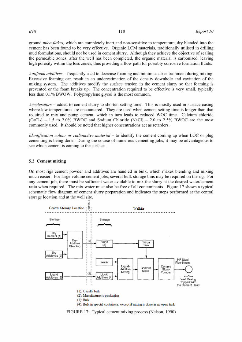
ground mica flakes, which are completely inert and non-sensitive to temperature, dry blended into the cement has been found to be very effective. Organic LCM materials, traditionally utilised in drilling mud formulations, should not be used in cement slurry. Although they achieve the objective of sealing the permeable zones, after the well has been completed, the organic material is carbonised, leaving high porosity within the loss zones, thus providing a flow path for possibly corrosive formation fluids. Antifoam additives – frequently used to decrease foaming and minimise air entrainment during mixing. Excessive foaming can result in an underestimation of the density downhole and cavitation of the mixing system. The additives modify the surface tension in the cement slurry so that foaming is prevented or the foam breaks up. The concentration required to be effective is very small, typically less than 0.1% BWOW. Polypropylene glycol is the most common. Accelerators – added to cement slurry to shorten setting time. This is mostly used in surface casing where low temperatures are encountered. They are used when cement setting time is longer than that required to mix and pump cement, which in turn leads to reduced WOC time. Calcium chloride (CaCl2) – 1.5 to 2.0% BWOC and Sodium Chloride (NaCl) – 2.0 to 2.5% BWOC are the most commonly used. It should be noted that higher concentrations act as retarders. Identification colour or radioactive material – to identify the cement coming up when LOC or plug cementing is being done. During the course of numerous cementing jobs, it may be advantageous to see which cement is coming to the surface. 5.2 Cement mixing On most rigs cement powder and additives are handled in bulk, which makes blending and mixing much easier. For large volume cement jobs, several bulk storage bins may be required on the rig. For any cement job, there must be sufficient water available to mix the slurry at the desired water/cement ratio when required. The mix-water must also be free of all contaminants. Figure 17 shows a typical schematic flow diagram of cement slurry preparation and indicates the steps performed at the central storage location and at the well site.
FIGURE 17: Typical cement mixing process (Nelson, 1990)
Report 10 111 Bett
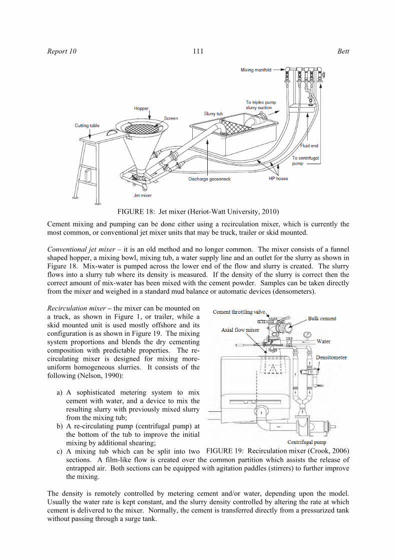
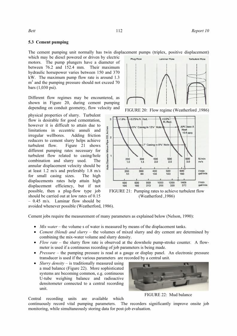
Cement mixing and pumping can be done either using a recirculation mixer, which is currently the most common, or conventional jet mixer units that may be truck, trailer or skid mounted. Conventional jet mixer – it is an old method and no longer common. The mixer consists of a funnel shaped hopper, a mixing bowl, mixing tub, a water supply line and an outlet for the slurry as shown in Figure 18. Mix-water is pumped across the lower end of the flow and slurry is created. The slurry flows into a slurry tub where its density is measured. If the density of the slurry is correct then the correct amount of mix-water has been mixed with the cement powder. Samples can be taken directly from the mixer and weighed in a standard mud balance or automatic devices (densometers). Recirculation mixer – the mixer can be mounted on a truck, as shown in Figure 1, or trailer, while a skid mounted unit is used mostly offshore and its configuration is as shown in Figure 19. The mixing system proportions and blends the dry cementing composition with predictable properties. The re-circulating mixer is designed for mixing more-uniform homogeneous slurries. It consists of the following (Nelson, 1990):
a) A sophisticated metering system to mix cement with water, and a device to mix the resulting slurry with previously mixed slurry from the mixing tub;
b) A re-circulating pump (centrifugal pump) at the bottom of the tub to improve the initial mixing by additional shearing;
c) A mixing tub which can be split into two sections. A film-like flow is created over the common partition which assists the release of entrapped air. Both sections can be equipped with agitation paddles (stirrers) to further improve the mixing.
The density is remotely controlled by metering cement and/or water, depending upon the model. Usually the water rate is kept constant, and the slurry density controlled by altering the rate at which cement is delivered to the mixer. Normally, the cement is transferred directly from a pressurized tank without passing through a surge tank.
FIGURE 19: Recirculation mixer (Crook, 2006)
FIGURE 18: Jet mixer (Heriot-Watt University, 2010)
Bett 112 Report 10
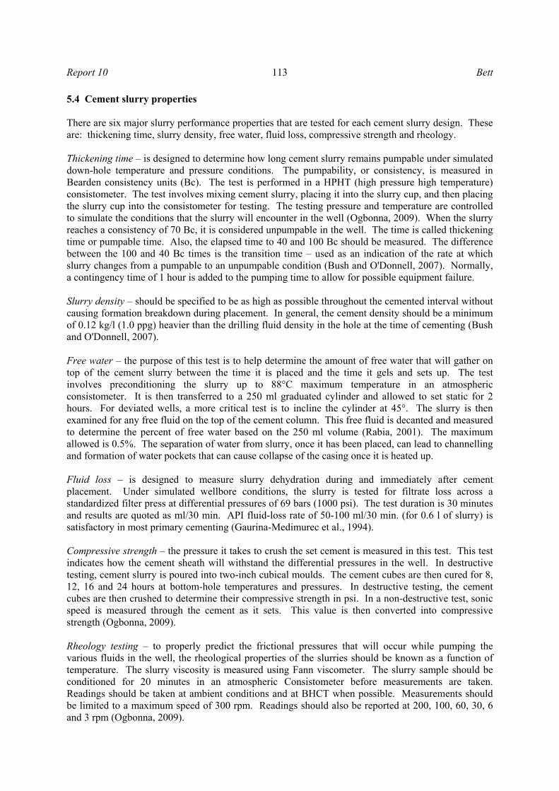
5.3 Cement pumping The cement pumping unit normally has twin displacement pumps (triplex, positive displacement) which may be diesel powered or driven by electric motors. The pump plungers have a diameter of between 76.2 and 152.4 mm. Their maximum hydraulic horsepower varies between 150 and 370 kW. The maximum pump flow rate is around 1.3 m3 and the pumping pressure should not exceed 70 bars (1,030 psi). Different flow regimes may be encountered, as shown in Figure 20, during cement pumping depending on conduit geometry, flow velocity and
physical properties of slurry. Turbulent flow is desirable for good cementation, however it is difficult to attain due to limitations in eccentric annuli and irregular wellbores. Adding friction reducers to cement slurry helps achieve turbulent flow. Figure 21 shows different pumping rates necessary for turbulent flow related to casing/hole combination and slurry used. The annular displacement velocity should be at least 1.2 m/s and preferably 1.8 m/s for small casing sizes. The high displacements rates help attain high displacement efficiency, but if not possible, then a plug-flow type job should be carried out at low rates of 0.15 – 0.45 m/s. Laminar flow should be avoided whenever possible (Weatherford, 1986). Cement jobs require the measurement of many parameters as explained below (Nelson, 1990):
• Mix water – the volume s of water is measured by means of the displacement tanks. • Cement (blend) and slurry – the volumes of mixed slurry and dry cement are determined by
combining the mix-water volume and slurry density. • Flow rate – the slurry flow rate is observed at the downhole pump-stroke counter. A flow-
meter is used if a continuous recording of job parameters is being made. • Pressure – the pumping pressure is read at a gauge or display panel. An electronic pressure
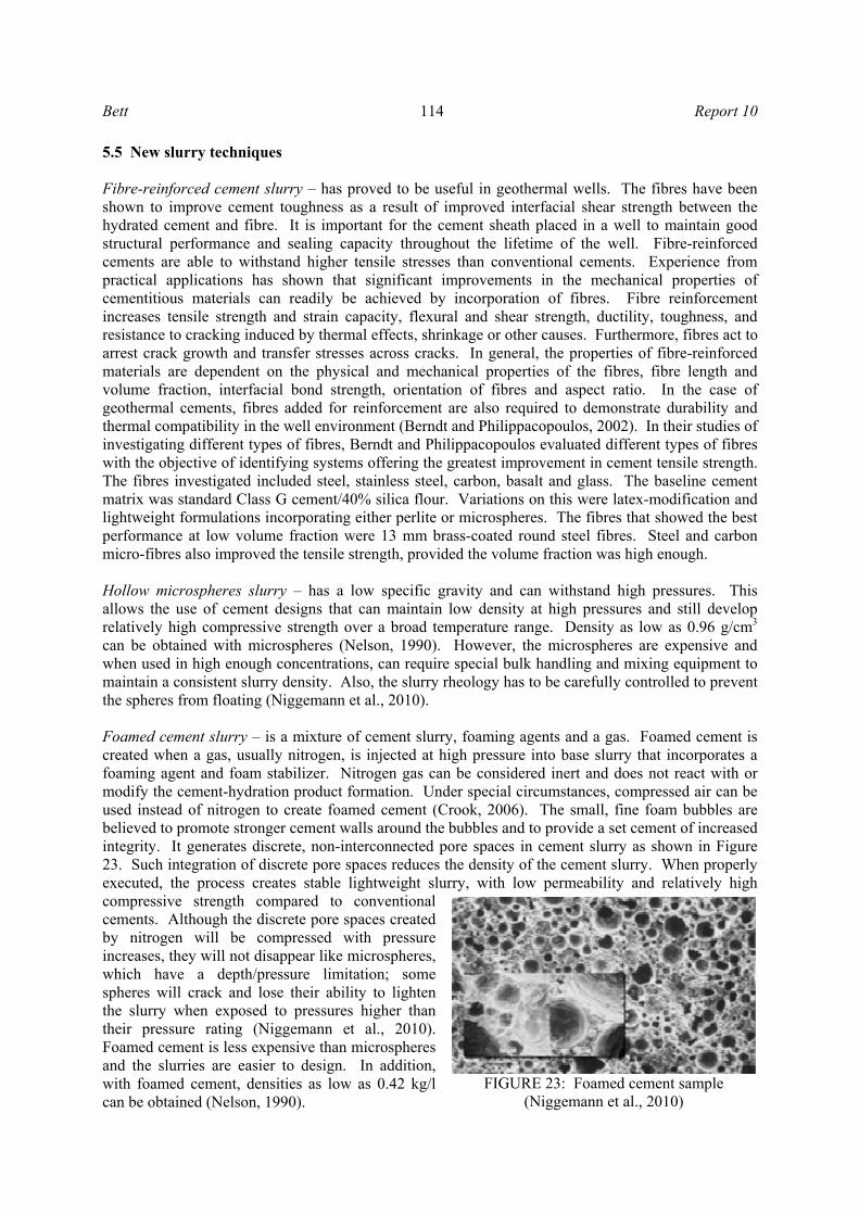
transducer is used if the various parameters are recorded by a central unit. • Slurry density – is traditionally measured using
a mud balance (Figure 22). More sophisticated systems are becoming common, e.g. continuous U-tube weighing balance and radioactive densitometer connected to a central recording unit.
Central recording units are available which continuously record vital pumping parameters. The recorders significantly improve onsite job monitoring, while simultaneously storing data for post-job evaluation.
FIGURE 20: Flow regime (Weatherford ,1986)
FIGURE 21: Pumping rates to achieve turbulent flow (Weatherford ,1986)
FIGURE 22: Mud balance
Report 10 113 Bett
5.4 Cement slurry properties There are six major slurry performance properties that are tested for each cement slurry design. These are: thickening time, slurry density, free water, fluid loss, compressive strength and rheology. Thickening time – is designed to determine how long cement slurry remains pumpable under simulated down-hole temperature and pressure conditions. The pumpability, or consistency, is measured in Bearden consistency units (Bc). The test is performed in a HPHT (high pressure high temperature) consistometer. The test involves mixing cement slurry, placing it into the slurry cup, and then placing the slurry cup into the consistometer for testing. The testing pressure and temperature are controlled to simulate the conditions that the slurry will encounter in the well (Ogbonna, 2009). When the slurry reaches a consistency of 70 Bc, it is considered unpumpable in the well. The time is called thickening time or pumpable time. Also, the elapsed time to 40 and 100 Bc should be measured. The difference between the 100 and 40 Bc times is the transition time – used as an indication of the rate at which slurry changes from a pumpable to an unpumpable condition (Bush and O'Donnell, 2007). Normally, a contingency time of 1 hour is added to the pumping time to allow for possible equipment failure. Slurry density – should be specified to be as high as possible throughout the cemented interval without causing formation breakdown during placement. In general, the cement density should be a minimum of 0.12 kg/l (1.0 ppg) heavier than the drilling fluid density in the hole at the time of cementing (Bush and O'Donnell, 2007). Free water – the purpose of this test is to help determine the amount of free water that will gather on top of the cement slurry between the time it is placed and the time it gels and sets up. The test involves preconditioning the slurry up to 88°C maximum temperature in an atmospheric consistometer. It is then transferred to a 250 ml graduated cylinder and allowed to set static for 2 hours. For deviated wells, a more critical test is to incline the cylinder at 45°. The slurry is then examined for any free fluid on the top of the cement column. This free fluid is decanted and measured to determine the percent of free water based on the 250 ml volume (Rabia, 2001). The maximum allowed is 0.5%. The separation of water from slurry, once it has been placed, can lead to channelling and formation of water pockets that can cause collapse of the casing once it is heated up. Fluid loss – is designed to measure slurry dehydration during and immediately after cement placement. Under simulated wellbore conditions, the slurry is tested for filtrate loss across a standardized filter press at differential pressures of 69 bars (1000 psi). The test duration is 30 minutes and results are quoted as ml/30 min. API fluid-loss rate of 50-100 ml/30 min. (for 0.6 l of slurry) is satisfactory in most primary cementing (Gaurina-Medimurec et al., 1994). Compressive strength – the pressure it takes to crush the set cement is measured in this test. This test indicates how the cement sheath will withstand the differential pressures in the well. In destructive testing, cement slurry is poured into two-inch cubical moulds. The cement cubes are then cured for 8, 12, 16 and 24 hours at bottom-hole temperatures and pressures. In destructive testing, the cement cubes are then crushed to determine their compressive strength in psi. In a non-destructive test, sonic speed is measured through the cement as it sets. This value is then converted into compressive strength (Ogbonna, 2009).
Rheology testing – to properly predict the frictional pressures that will occur while pumping the various fluids in the well, the rheological properties of the slurries should be known as a function of temperature. The slurry viscosity is measured using Fann viscometer. The slurry sample should be conditioned for 20 minutes in an atmospheric Consistometer before measurements are taken. Readings should be taken at ambient conditions and at BHCT when possible. Measurements should be limited to a maximum speed of 300 rpm. Readings should also be reported at 200, 100, 60, 30, 6 and 3 rpm (Ogbonna, 2009).
Bett 114 Report 10
5.5 New slurry techniques Fibre-reinforced cement slurry – has proved to be useful in geothermal wells. The fibres have been shown to improve cement toughness as a result of improved interfacial shear strength between the hydrated cement and fibre. It is important for the cement sheath placed in a well to maintain good structural performance and sealing capacity throughout the lifetime of the well. Fibre-reinforced cements are able to withstand higher tensile stresses than conventional cements. Experience from practical applications has shown that significant improvements in the mechanical properties of cementitious materials can readily be achieved by incorporation of fibres. Fibre reinforcement increases tensile strength and strain capacity, flexural and shear strength, ductility, toughness, and resistance to cracking induced by thermal effects, shrinkage or other causes. Furthermore, fibres act to arrest crack growth and transfer stresses across cracks. In general, the properties of fibre-reinforced materials are dependent on the physical and mechanical properties of the fibres, fibre length and volume fraction, interfacial bond strength, orientation of fibres and aspect ratio. In the case of geothermal cements, fibres added for reinforcement are also required to demonstrate durability and thermal compatibility in the well environment (Berndt and Philippacopoulos, 2002). In their studies of investigating different types of fibres, Berndt and Philippacopoulos evaluated different types of fibres with the objective of identifying systems offering the greatest improvement in cement tensile strength. The fibres investigated included steel, stainless steel, carbon, basalt and glass. The baseline cement matrix was standard Class G cement/40% silica flour. Variations on this were latex-modification and lightweight formulations incorporating either perlite or microspheres. The fibres that showed the best performance at low volume fraction were 13 mm brass-coated round steel fibres. Steel and carbon micro-fibres also improved the tensile strength, provided the volume fraction was high enough. Hollow microspheres slurry – has a low specific gravity and can withstand high pressures. This allows the use of cement designs that can maintain low density at high pressures and still develop relatively high compressive strength over a broad temperature range. Density as low as 0.96 g/cm3 can be obtained with microspheres (Nelson, 1990). However, the microspheres are expensive and when used in high enough concentrations, can require special bulk handling and mixing equipment to maintain a consistent slurry density. Also, the slurry rheology has to be carefully controlled to prevent the spheres from floating (Niggemann et al., 2010). Foamed cement slurry – is a mixture of cement slurry, foaming agents and a gas. Foamed cement is created when a gas, usually nitrogen, is injected at high pressure into base slurry that incorporates a foaming agent and foam stabilizer. Nitrogen gas can be considered inert and does not react with or modify the cement-hydration product formation. Under special circumstances, compressed air can be used instead of nitrogen to create foamed cement (Crook, 2006). The small, fine foam bubbles are believed to promote stronger cement walls around the bubbles and to provide a set cement of increased integrity. It generates discrete, non-interconnected pore spaces in cement slurry as shown in Figure 23. Such integration of discrete pore spaces reduces the density of the cement slurry. When properly executed, the process creates stable lightweight slurry, with low permeability and relatively high compressive strength compared to conventional cements. Although the discrete pore spaces created by nitrogen will be compressed with pressure increases, they will not disappear like microspheres, which have a depth/pressure limitation; some spheres will crack and lose their ability to lighten the slurry when exposed to pressures higher than their pressure rating (Niggemann et al., 2010). Foamed cement is less expensive than microspheres and the slurries are easier to design. In addition, with foamed cement, densities as low as 0.42 kg/l can be obtained (Nelson, 1990).
FIGURE 23: Foamed cement sample (Niggemann et al., 2010)
Report 10 115 Bett
6. CEMENTING JOB 6.1 Pre-job preparation To obtain a good cement job, it is important to be familiar with the wellbore conditions, design, materials and equipment available, try to think of unexpected LOC zones and how to react without delay. When cementing has started, there is not much time to do calculations, so be well prepared for unexpected events. The following are the preparations that need to be done before cementing job execution (Bush and O'Donnell, 2007; Drilling and Completion Committee, 1995):
1. Obtain the following information: hole depth, hole size with caliper data and required excess factor, casing information (length, size and weight), drill pipe information (length, size and weight), shoe track dimensions, length of rat hole, BHCT, BHST, any special well problem (lost circulation, salt sections, etc.) and any other pertinent information.
2. Determine the required amount of dry cement or blend, total mix water, liquid additives (if any), displacement volume and the resultant mix fluid volume.
3. Calculate the pump rates, surface and bottom-hole pressures during the job, mixing time, job time, and any other relevant information.
4. Calculate also the hydraulic lifting force that the casing string will experience just before the plug is pumped. This is the moment of maximum differential pressure.
5. Physically confirm that all the required equipment and materials (including mix water quantities) have been delivered to the location.
6. Sometimes, cement blowing and sieving between silos is required and should be done prior to the job.
7. Service company engineers and company representatives should independently recalculate the slurry volumes and displacements required. Changes to the original job program should be mutually agreed to and verified.
8. Service company engineers and company representatives should also review the laboratory blend results, paying special attention to the thickening time and the required WOC. Check whether the available pumping time as indicated by the lab thickening time test result is sufficient for the planned job.
9. Develop a pumping schedule based on the cement job simulator output. 10. Prepare a job plan that includes the following: rig up procedure, safety concerns, pressure
testing procedure, spacer type, density and volumes to be pumped, wiper plug, dart/ball dropping sequence and procedure, conversion factors for calculating sacks per unit volume of slurry, and unit volume of slurry per unit volume of mix water, personnel requirements for the job, and contingency plans for the unexpected (float equipment failure, loss of returns while running in casing).
11. Rig up cementing equipment on location and discuss post job wash-up procedures and disposal. 12. The company representative should witness the installation of the float equipment and ensure
that casing centralizers are placed according to the centralizer program. 13. The company representative should also witness the pre-loading of top and bottom plugs into
the cementing head. 14. Complete the hook up of all equipment. As soon as the casing is landed, rig cementing head to
casing and begin circulation to condition the well. 6.2 Cement job execution It is important to have a clear and simple written plan and for all cementing personnel to know the procedure. During cementing, communication is often difficult due to noisy equipment and stress. The following is a general procedure to be followed during job execution (Bush and O'Donnell, 2007; Drilling and Completion Committee, 1995):
Bett 116 Report 10
1. Conduct a safety meeting on the location with the cementing crew, company representative and the rig personnel who will be involved with the job; review the job procedures, safety procedures, and assign support responsibilities.
2. Pressure-test all high pressure lines and the cementing manifold with water or spacer prior to pumping any fluid into the casing and reconfirm the maximum allowable pressures. Test pressure should be at least 69 bars (1000 psi) above maximum anticipated pumping pressure during cementing operations. Note: the cementing head is usually the weakest link during a cementing operation and it should be noted that the cementing head maximum working pressure is often below the casing burst pressure.
3. Pressurize the bulk cement tanks. 4. Use a data acquisition system to record pumping rate, density and volumes pumped during the
cementing job. 5. Start the pumping operation by establishing circulation from the cement equipment. Observe
mud tanks or pits for returns. 6. Pump water (spacer) which is meant to minimise contamination of cement slurry by the mud in
the annulus. The spacer should occupy 100 m of the annulus so as to provide sufficient separation of mud and cement in the annulus; 3-8 m3 of spacer is common.
7. The water spacer is followed with either 1.5 m3 of high density polymer (water mixed with viscosifying polyacrylamide polymer – 5-10 kg/m3) or 4.0 m3 of scavenge cement slurry with a density of 1.2 kg/l (10 ppg).
8. Mix and pump cement slurry as per design densities and rates. The pumping rate is 0.8-1.0 m3. Measure and record the mix water and check electronic density measurements against the pressurized mud balance measurements.
9. Collect samples of the dry blended cement and mix water as mixing progresses. Samples must be taken in clean, well marked containers and stored securely at proper temperatures should they be required for post job evaluation.
10. Take slurry samples during the job. Do not use the setting of the surface samples as a guide to cement working time or drill out times. They do not accurately reflect the downhole condition of cement during or after placement.
11. Observe the well for returns during the entire cementing process. If possible, record the volume and densities of the returns.
12. Do not maintain the designed downhole rate at the expense of slurry density. If the density cannot be controlled within the acceptable limits (±25 kg/m3 or ±0.25 ppg), the pump rate needs to be adjusted until the slurry density control is acceptable.
13. Switch to water without shutting down and try to maintain a steady pump rate throughout the displacement. Note: a) Depending on the pump rate, additional pressure may be required to overcome friction
pressure. These pressures are calculated to determine the type of pump required, to ensure that the cementing head is adequate and that there is no danger of bursting the casing.
b) To ensure the safety of the well, it is necessary to determine if it is likely that the well will flow or be fractured during or after the cement placement. This is done by calculating the hydrostatics at the critical points in the wellbore.
14. Bleed off the pressure. Check if the plug holds. If it does not, leave the casing valve closed to provide a hydraulic lock. Bleed off the pressure every two hours until the cement is set or fluid stops flowing out of the casing.
15. Apart from parameters recorded in 4 above, also record the following events: pressure test (psi) and time, start time for the job, start and stop time for each fluid pumped, start of displacement and any observed pressure.
16. Wait on cement for 20-24 hours before drilling. This is required in order that the cement anchors the pipe and withstands the shocks of subsequent operations.
17. Store two of the samples at hole temperature to see when they harden.
Report 10 117 Bett
6.3 Post-job cement evaluation To obtain a good cement bond, the annulus has to be filled to the surface by well designed cement slurry, based on wellbore conditions. There has to be an excellent bond between casing and cement and between the cement and the formation. A primary cement job can be considered a failure if the cement does not isolate undesirable zones. This will occur if:
• There are water pockets in between casings; • The cement does not fully fill the annulus; • The cement does not provide a good seal between the casing and borehole and fluid leaks
through the cement sheath to the surface; • The cement does not provide a good seal at the casing shoe or a poor leak-off test is achieved.
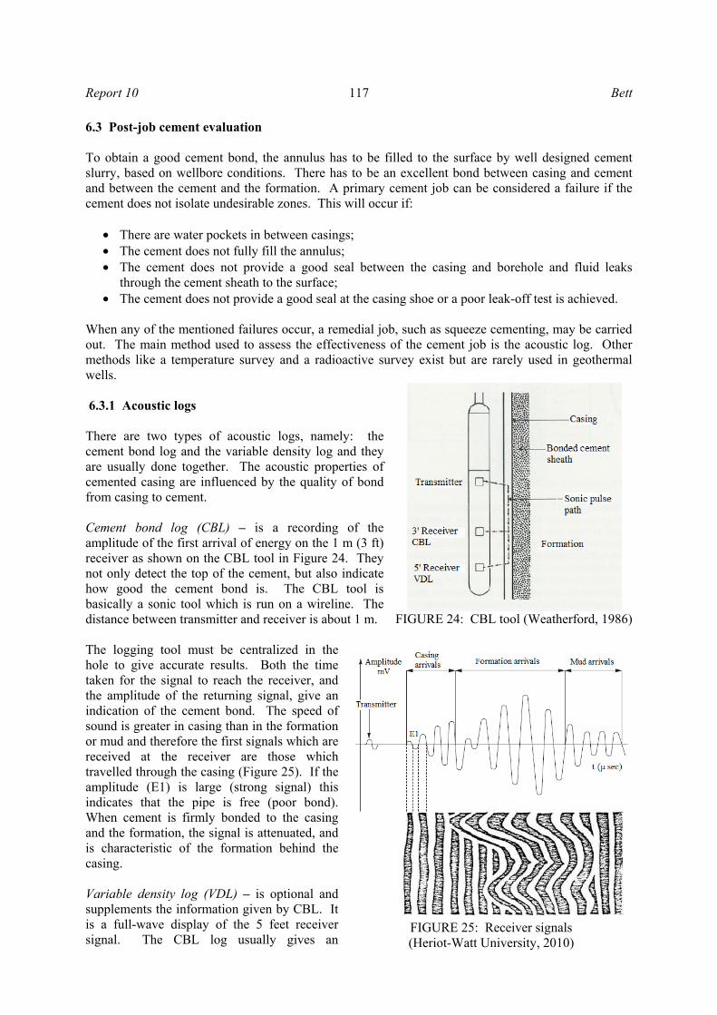
When any of the mentioned failures occur, a remedial job, such as squeeze cementing, may be carried out. The main method used to assess the effectiveness of the cement job is the acoustic log. Other methods like a temperature survey and a radioactive survey exist but are rarely used in geothermal wells. 6.3.1 Acoustic logs There are two types of acoustic logs, namely: the cement bond log and the variable density log and they are usually done together. The acoustic properties of cemented casing are influenced by the quality of bond from casing to cement. Cement bond log (CBL) – is a recording of the amplitude of the first arrival of energy on the 1 m (3 ft) receiver as shown on the CBL tool in Figure 24. They not only detect the top of the cement, but also indicate how good the cement bond is. The CBL tool is basically a sonic tool which is run on a wireline. The distance between transmitter and receiver is about 1 m. The logging tool must be centralized in the hole to give accurate results. Both the time taken for the signal to reach the receiver, and the amplitude of the returning signal, give an indication of the cement bond. The speed of sound is greater in casing than in the formation or mud and therefore the first signals which are received at the receiver are those which travelled through the casing (Figure 25). If the amplitude (E1) is large (strong signal) this indicates that the pipe is free (poor bond). When cement is firmly bonded to the casing and the formation, the signal is attenuated, and is characteristic of the formation behind the casing. Variable density log (VDL) – is optional and supplements the information given by CBL. It is a full-wave display of the 5 feet receiver signal. The CBL log usually gives an
FIGURE 24: CBL tool (Weatherford, 1986)
FIGURE 25: Receiver signals (Heriot-Watt University, 2010)
Bett 118 Report 10
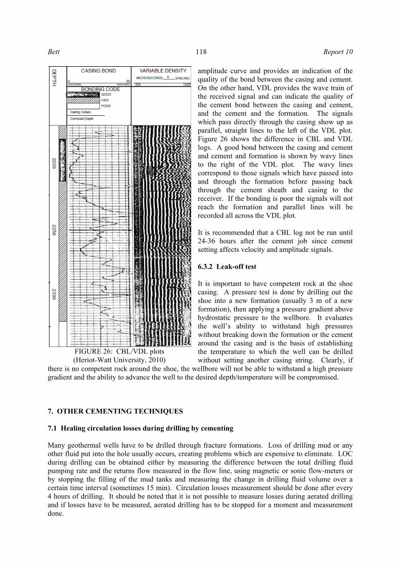
amplitude curve and provides an indication of the quality of the bond between the casing and cement. On the other hand, VDL provides the wave train of the received signal and can indicate the quality of the cement bond between the casing and cement, and the cement and the formation. The signals which pass directly through the casing show up as parallel, straight lines to the left of the VDL plot. Figure 26 shows the difference in CBL and VDL logs. A good bond between the casing and cement and cement and formation is shown by wavy lines to the right of the VDL plot. The wavy lines correspond to those signals which have passed into and through the formation before passing back through the cement sheath and casing to the receiver. If the bonding is poor the signals will not reach the formation and parallel lines will be recorded all across the VDL plot. It is recommended that a CBL log not be run until 24-36 hours after the cement job since cement setting affects velocity and amplitude signals. 6.3.2 Leak-off test It is important to have competent rock at the shoe casing. A pressure test is done by drilling out the shoe into a new formation (usually 3 m of a new formation), then applying a pressure gradient above hydrostatic pressure to the wellbore. It evaluates the well’s ability to withstand high pressures without breaking down the formation or the cement around the casing and is the basis of establishing the temperature to which the well can be drilled without setting another casing string. Clearly, if
there is no competent rock around the shoe, the wellbore will not be able to withstand a high pressure gradient and the ability to advance the well to the desired depth/temperature will be compromised. 7. OTHER CEMENTING TECHNIQUES 7.1 Healing circulation losses during drilling by cementing Many geothermal wells have to be drilled through fracture formations. Loss of drilling mud or any other fluid put into the hole usually occurs, creating problems which are expensive to eliminate. LOC during drilling can be obtained either by measuring the difference between the total drilling fluid pumping rate and the returns flow measured in the flow line, using magnetic or sonic flow-meters or by stopping the filling of the mud tanks and measuring the change in drilling fluid volume over a certain time interval (sometimes 15 min). Circulation losses measurement should be done after every 4 hours of drilling. It should be noted that it is not possible to measure losses during aerated drilling and if losses have to be measured, aerated drilling has to be stopped for a moment and measurement done.
FIGURE 26: CBL/VDL plots (Heriot-Watt University, 2010)
Report 10 119 Bett
LOC is the primary problem in geothermal drilling and cementing and it is common to deal with much higher LOC than in oil drilling. If the rate of returns becomes smaller and smaller until the mud loss approaches 5 l/s, the normal procedure is to add LCM to the mud and hope that full returns can be achieved. Quite often, this is unsuccessful. If circulation losses encountered cannot be regained with LCM, drill blind with water and high viscosity gel sweeps at every connection or more frequently depending on the hole conditions. When drilling blind, the build up of cuttings should be monitored. If the total loss of circulation is experienced and persists, drilling has to be stopped and the loss zone cemented after drilling a 30 m rat hole by placing a cement plug. Wait 4 hours before trying to fill the hole. This allows the cement slurry time to thicken and become more resistant to flow when subjected to an increased hydrostatic head. After waiting for 4 hours, an attempt is made to fill the hole, pumping 15% more than required without getting returns. The decision has to be made whether to wait longer or do a second job. Normal practice in geothermal well lost circulation cement plug jobs is to do a second job when unable to fill the hole following the first job. The second job is done similar to the first, only waiting longer for the cement to set. Eight hours following the second job, the hole is filled and the drill pipe lowered to tag on hard cement (Shyrock and Smith, 1980). Cementing LOC zones may often be unsuccessful if the cement cannot bond well with the walls and can shave off during further drilling. Thus, it is advantageous to put a colour identifier in the cement to identify different LOC cement jobs and know which one is breaking down. When cement has proven unsuccessful as a cure for lost circulation during drilling, it is time to consider a new approach. This would involve pumping another material into the hole ahead of the cement. One such material is Halliburton’s Flo-Chek chemical. It is a colourless liquid that instantly forms a stiff gel sealing off lost-circulation zones by blocking flow channels and fractures and also helps prevent slurry migration down away from the plug location. The procedure would then be to pump some water through the open-ended drill pipe as near the lost circulation zone as possible, following it with 4-8 m3 of LCM material. A 0.8-1.5 m3 spacer of fresh water should follow the LCM material, then 3-6 m3 of cement slurry. Displace with water until the LCM material has been displaced from the drill pipe. Then pull the drill pipe above the cement and circulate at a low pressure to fill the hole. If returns are obtained, the cement needs 8-10 hours to harden (Shyrock and Smith, 1980). 7.2 Cement plugs At some stage during the life of a well, a cement plug may have to be placed in the wellbore. It involves the placement of a relatively small amount of cement slurry inside an open hole or inside a casing. The main reasons for setting a cement plug are:
• To seal off lost circulation zones; • To sidetrack above a fish or to initiate a sidetrack; • To plug back a zone or abandon a well; • To isolate a zone for formation testing.
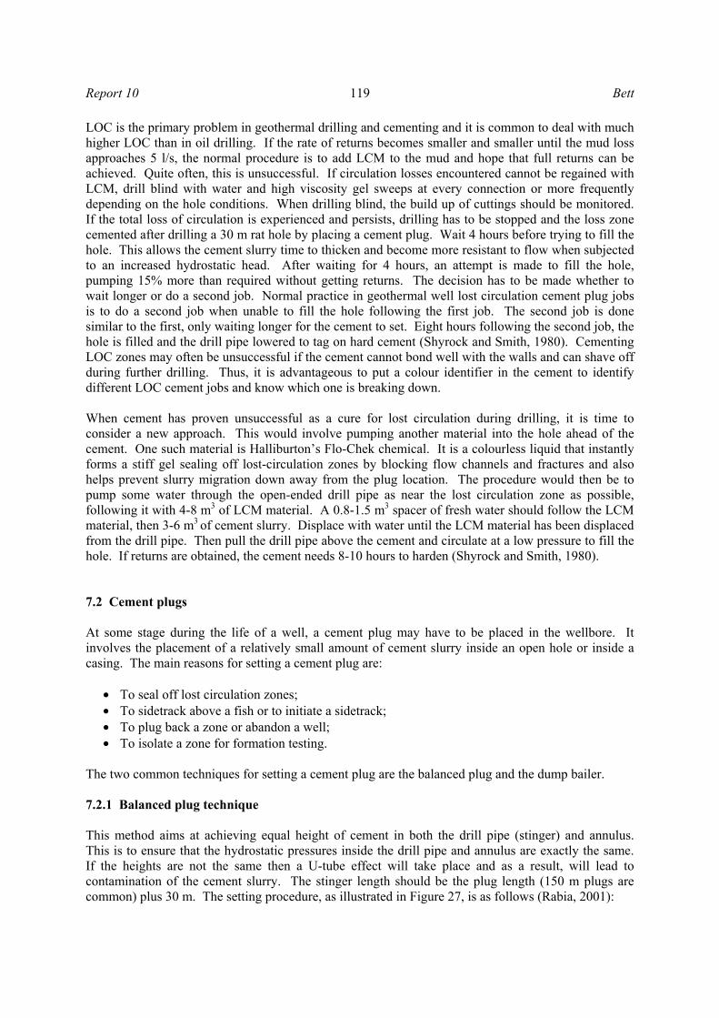
The two common techniques for setting a cement plug are the balanced plug and the dump bailer. 7.2.1 Balanced plug technique This method aims at achieving equal height of cement in both the drill pipe (stinger) and annulus. This is to ensure that the hydrostatic pressures inside the drill pipe and annulus are exactly the same. If the heights are not the same then a U-tube effect will take place and as a result, will lead to contamination of the cement slurry. The stinger length should be the plug length (150 m plugs are common) plus 30 m. The setting procedure, as illustrated in Figure 27, is as follows (Rabia, 2001):
Bett 120 Report 10
a) Run the stinger to, say, 90 m below the bottom setting depth for the plug.
b) Spot a viscous mud pill having the same density as the mud in hole. The volume of the pill should be sufficient to cover the 90 m interval. A pill is not required if the cement plug is to be set on the bottom, or on top of a bridge plug (cement retainer).
c) Pull the stinger back to 90 m.
d) Pump a 1.5-3.0 m3 spacer (pre-flush). The exact volume will depend on the hole size. Pump a sufficient volume of slurry for the 150 m plug or as specified in the drilling program. The slurry should be displaced at maximum rate. The rate should be slowed down to around 0.3 m3/min when the cement is 1.5-3.0 m3 away from the ported sub in the stinger and kept at this rate.
e) Pump sufficient spacer behind the cement to balance the pre-flush. f) Displace the mud to the balanced position. g) Pull back slowly to at least 150 m above the top of the plug and reverse circulate clean.
Note: If a series of plugs are to be set on top of each other, then reverse circulate immediately above the bottom plug before attempting to set the next plug.
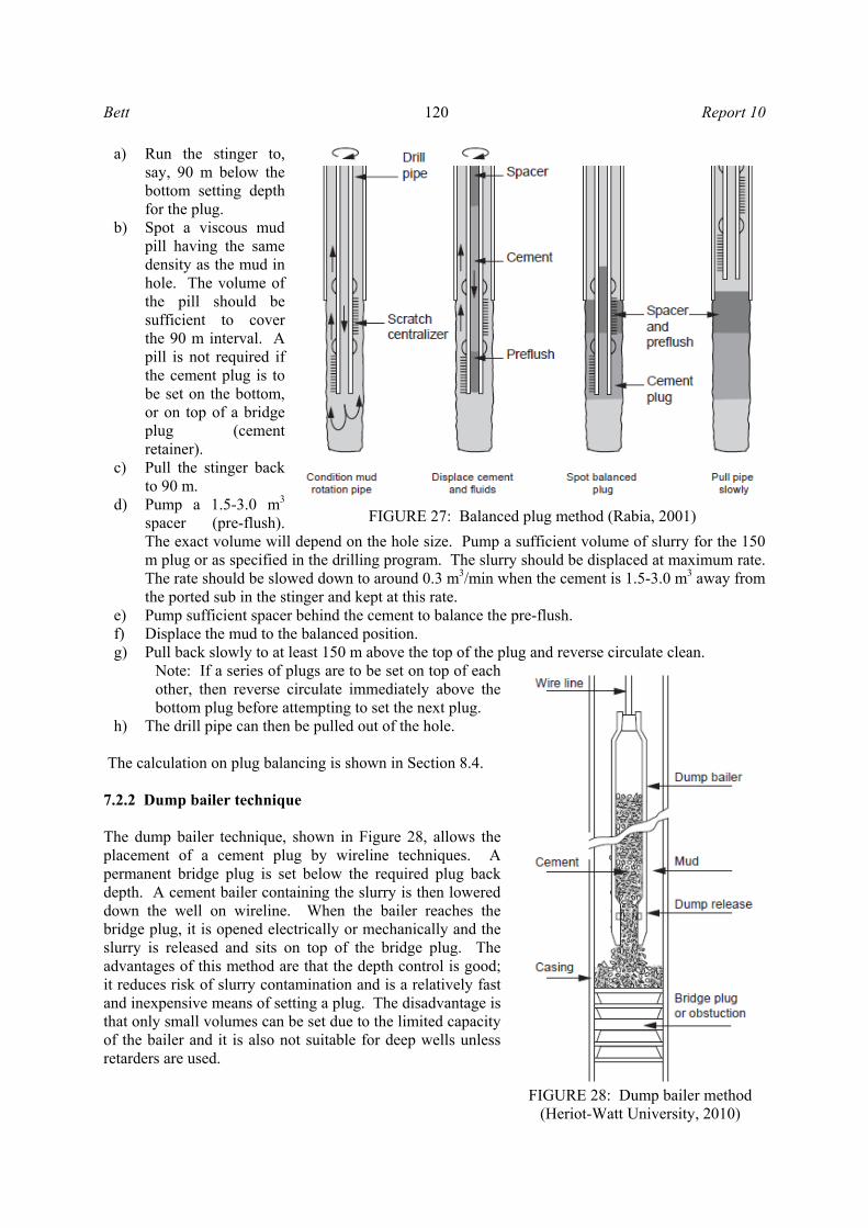
h) The drill pipe can then be pulled out of the hole. The calculation on plug balancing is shown in Section 8.4. 7.2.2 Dump bailer technique The dump bailer technique, shown in Figure 28, allows the placement of a cement plug by wireline techniques. A permanent bridge plug is set below the required plug back depth. A cement bailer containing the slurry is then lowered down the well on wireline. When the bailer reaches the bridge plug, it is opened electrically or mechanically and the slurry is released and sits on top of the bridge plug. The advantages of this method are that the depth control is good; it reduces risk of slurry contamination and is a relatively fast and inexpensive means of setting a plug. The disadvantage is that only small volumes can be set due to the limited capacity of the bailer and it is also not suitable for deep wells unless retarders are used.
FIGURE 27: Balanced plug method (Rabia, 2001)
FIGURE 28: Dump bailer method (Heriot-Watt University, 2010)
Report 10 121 Bett
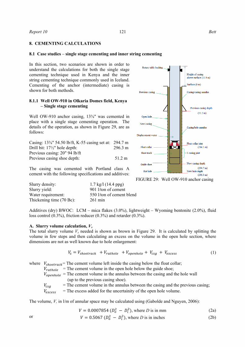
8. CEMENTING CALCULATIONS 8.1 Case studies – single stage cementing and inner string cementing In this section, two scenarios are shown in order to understand the calculations for both the single stage cementing technique used in Kenya and the inner string cementing technique commonly used in Iceland. Cementing of the anchor (intermediate) casing is shown for both methods. 8.1.1 Well OW-910 in Olkaria Domes field, Kenya – Single stage cementing Well OW-910 anchor casing, 13⅜" was cemented in place with a single stage cementing operation. The details of the operation, as shown in Figure 29, are as follows: Casing: 13⅜" 54.50 lb/ft, K-55 casing set at: 294.7 m Drill bit: 17½" hole depth: 296.3 m Previous casing: 20" 94 lb/ft Previous casing shoe depth: 51.2 m The casing was cemented with Portland class A cement with the following specifications and additives: Slurry density: 1.7 kg/l (14.4 ppg) Slurry yield: 901 l/ton of cement Water requirement: 550 l/ton of cement blend Thickening time (70 Bc): 261 min Additives (dry) BWOC: LCM – mica flakes (3.0%), lightweight – Wyoming bentonite (2.0%), fluid loss control (0.3%), friction reducer (0.3%) and retarder (0.3%). A. Slurry volume calculation, Vs The total slurry volume Vs needed is shown as brown in Figure 29. It is calculated by splitting the volume in few steps and then calculating an excess on the volume in the open hole section, where dimensions are not as well known due to hole enlargement: (1) where = The cement volume left inside the casing below the float collar; = The cement volume in the open hole below the guide shoe; = The cement volume in the annulus between the casing and the hole wall (up to the previous casing shoe). = The cement volume in the annulus between the casing and the previous casing; = The excess added for the uncertainity of the open hole volume. The volume, V, in l/m of annular space may be calculated using (Gabolde and Nguyen, 2006):
0.0007854 , where D is in mm (2a)or 0.5067 , where D is in inches (2b)
FIGURE 29: Well OW-910 anchor casing
Bett 122 Report 10
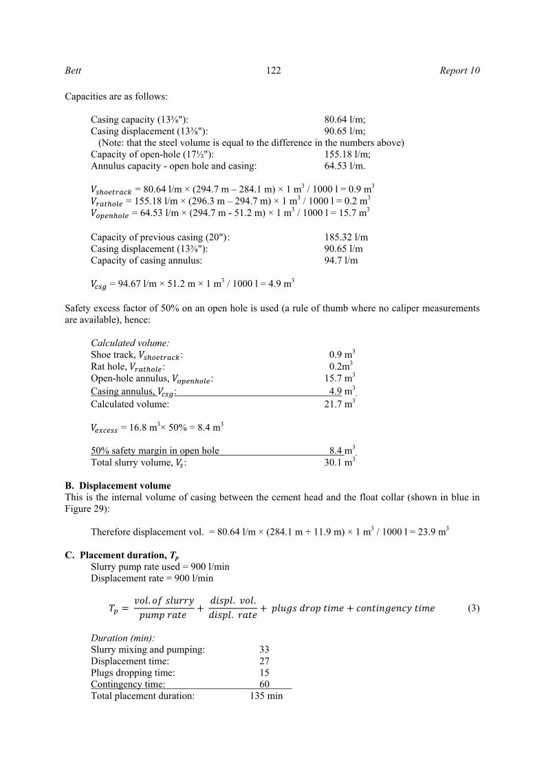
Capacities are as follows:
Casing capacity (13⅜"): 80.64 l/m; Casing displacement (13⅜"): 90.65 l/m; (Note: that the steel volume is equal to the difference in the numbers above) Capacity of open-hole (17½"): 155.18 l/m; Annulus capacity - open hole and casing: 64.53 l/m.
= 80.64 l/m × (294.7 m – 284.1 m) × 1 m3 / 1000 l = 0.9 m3 = 155.18 l/m × (296.3 m – 294.7 m) × 1 m3 / 1000 l = 0.2 m3
= 64.53 l/m × (294.7 m - 51.2 m) × 1 m3 / 1000 l = 15.7 m3 Capacity of previous casing (20") : 185.32 l/m Casing displacement (13⅜"): 90.65 l/m Capacity of casing annulus: 94.7 l/m
= 94.67 l/m × 51.2 m × 1 m3 / 1000 l = 4.9 m3
Safety excess factor of 50% on an open hole is used (a rule of thumb where no caliper measurements are available), hence:
Calculated volume: Shoe track, : 0.9 m3 Rat hole, : 0.2m3 Open-hole annulus, : 15.7 m3 Casing annulus, : 4.9 m3 Calculated volume: 21.7 m3
= 16.8 m3× 50% = 8.4 m3 50% safety margin in open hole 8.4 m3 Total slurry volume, : 30.1 m3
B. Displacement volume This is the internal volume of casing between the cement head and the float collar (shown in blue in Figure 29):
Therefore displacement vol. = 80.64 l/m × (284.1 m + 11.9 m) × 1 m3 / 1000 l = 23.9 m3 C. Placement duration, Tp
Slurry pump rate used = 900 l/min Displacement rate = 900 l/min
. . .. (3)
Duration (min): Slurry mixing and pumping: 33 Displacement time: 27 Plugs dropping time: 15 Contingency time: 60 Total placement duration: 135 min
Report 10 123 Bett
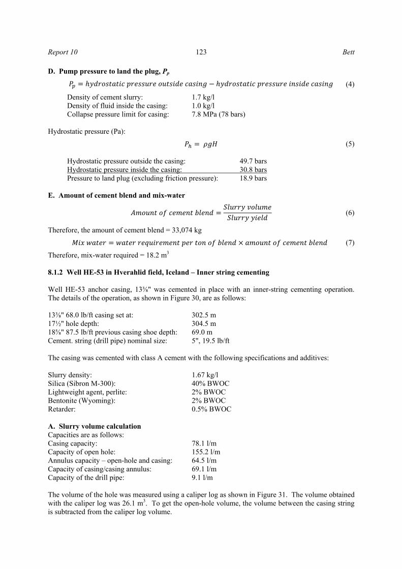
D. Pump pressure to land the plug, Pp
(4)
Density of cement slurry: 1.7 kg/l Density of fluid inside the casing: 1.0 kg/l Collapse pressure limit for casing: 7.8 MPa (78 bars)
Hydrostatic pressure (Pa):
(5)
Hydrostatic pressure outside the casing: 49.7 bars Hydrostatic pressure inside the casing: 30.8 bars Pressure to land plug (excluding friction pressure): 18.9 bars
E. Amount of cement blend and mix-water
(6)
Therefore, the amount of cement blend = 33,074 kg
(7)
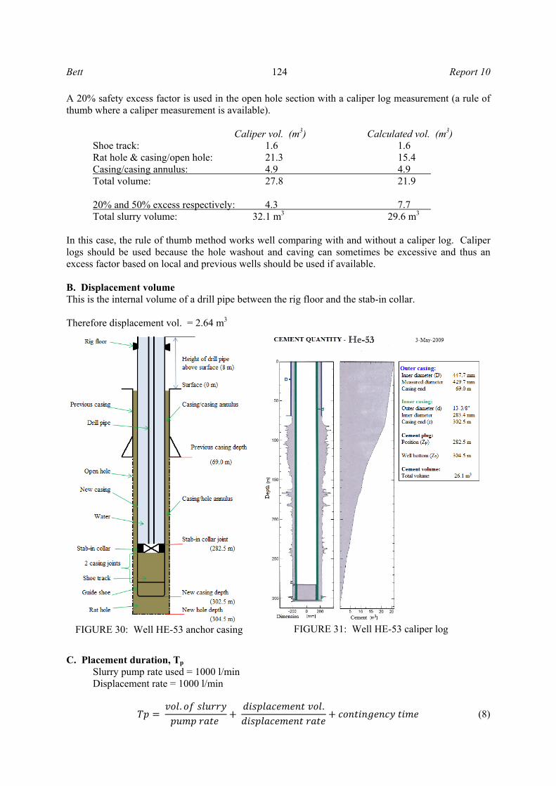
Therefore, mix-water required = 18.2 m3 8.1.2 Well HE-53 in Hverahlid field, Iceland – Inner string cementing Well HE-53 anchor casing, 13⅜" was cemented in place with an inner-string cementing operation. The details of the operation, as shown in Figure 30, are as follows: 13⅜" 68.0 lb/ft casing set at: 302.5 m 17½" hole depth: 304.5 m 18⅝" 87.5 lb/ft previous casing shoe depth: 69.0 m Cement. string (drill pipe) nominal size: 5", 19.5 lb/ft The casing was cemented with class A cement with the following specifications and additives: Slurry density: 1.67 kg/l Silica (Sibron M-300): 40% BWOC Lightweight agent, perlite: 2% BWOC Bentonite (Wyoming): 2% BWOC Retarder: 0.5% BWOC
A. Slurry volume calculation Capacities are as follows: Casing capacity: 78.1 l/m Capacity of open hole: 155.2 l/m Annulus capacity – open-hole and casing: 64.5 l/m Capacity of casing/casing annulus: 69.1 l/m Capacity of the drill pipe: 9.1 l/m The volume of the hole was measured using a caliper log as shown in Figure 31. The volume obtained with the caliper log was 26.1 m3. To get the open-hole volume, the volume between the casing string is subtracted from the caliper log volume.
Bett 124 Report 10
A 20% safety excess factor is used in the open hole section with a caliper log measurement (a rule of thumb where a caliper measurement is available).
Caliper vol. (m3) Calculated vol. (m3) Shoe track: 1.6 1.6 Rat hole & casing/open hole: 21.3 15.4 Casing/casing annulus: 4.9 4.9 Total volume: 27.8 21.9
20% and 50% excess respectively: 4.3 7.7 Total slurry volume: 32.1 m3 29.6 m3
In this case, the rule of thumb method works well comparing with and without a caliper log. Caliper logs should be used because the hole washout and caving can sometimes be excessive and thus an excess factor based on local and previous wells should be used if available. B. Displacement volume This is the internal volume of a drill pipe between the rig floor and the stab-in collar. Therefore displacement vol. = 2.64 m3
C. Placement duration, Tp
Slurry pump rate used = 1000 l/min Displacement rate = 1000 l/min
. . (8)
FIGURE 31: Well HE-53 caliper log FIGURE 30: Well HE-53 anchor casing
Report 10 125 Bett
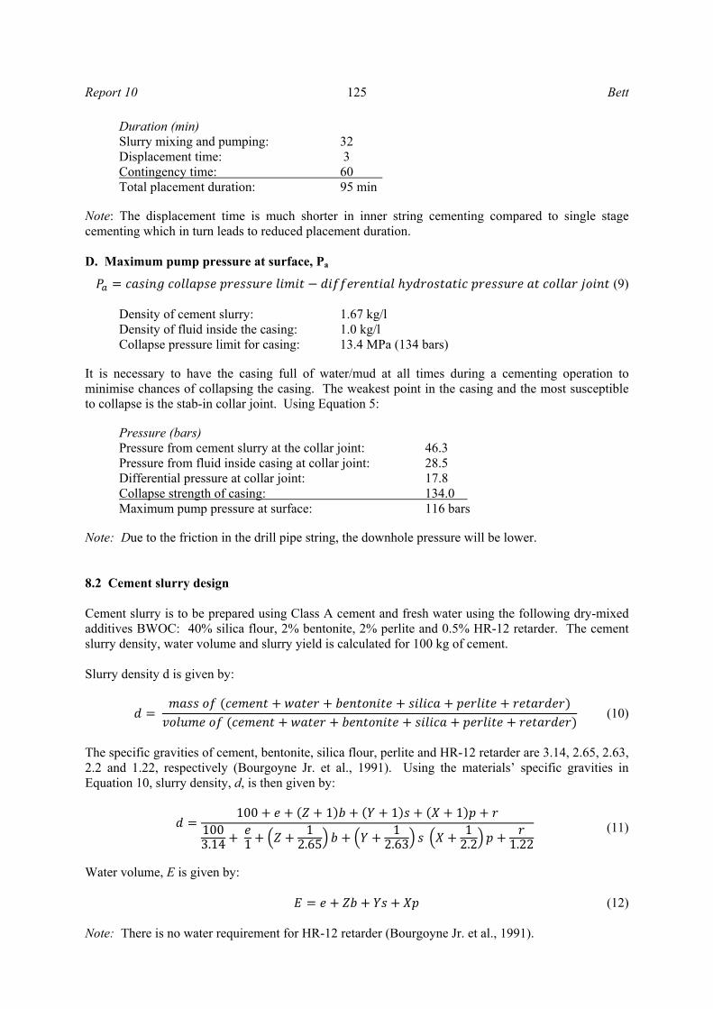
Duration (min) Slurry mixing and pumping: 32 Displacement time: 3 Contingency time: 60 Total placement duration: 95 min
Note: The displacement time is much shorter in inner string cementing compared to single stage cementing which in turn leads to reduced placement duration. D. Maximum pump pressure at surface, Pa (9)
Density of cement slurry: 1.67 kg/l Density of fluid inside the casing: 1.0 kg/l Collapse pressure limit for casing: 13.4 MPa (134 bars)
It is necessary to have the casing full of water/mud at all times during a cementing operation to minimise chances of collapsing the casing. The weakest point in the casing and the most susceptible to collapse is the stab-in collar joint. Using Equation 5:
Pressure (bars) Pressure from cement slurry at the collar joint: 46.3 Pressure from fluid inside casing at collar joint: 28.5 Differential pressure at collar joint: 17.8 Collapse strength of casing: 134.0 Maximum pump pressure at surface: 116 bars
Note: Due to the friction in the drill pipe string, the downhole pressure will be lower. 8.2 Cement slurry design Cement slurry is to be prepared using Class A cement and fresh water using the following dry-mixed additives BWOC: 40% silica flour, 2% bentonite, 2% perlite and 0.5% HR-12 retarder. The cement slurry density, water volume and slurry yield is calculated for 100 kg of cement. Slurry density d is given by: (10)
The specific gravities of cement, bentonite, silica flour, perlite and HR-12 retarder are 3.14, 2.65, 2.63, 2.2 and 1.22, respectively (Bourgoyne Jr. et al., 1991). Using the materials’ specific gravities in Equation 10, slurry density, d, is then given by: 100 1 1 11003.14 1 12.65 12.63 12.2 1.22 (11)
Water volume, E is given by: (12) Note: There is no water requirement for HR-12 retarder (Bourgoyne Jr. et al., 1991).
Bett 126 Report 10
Slurry yield v is given by:
1003.14 2.65 2.63 2.2 1.22 (13)
Data values are as follows:
e = 46 l for class A cement Z = 5.3 l per kg of bentonite when dry mixed (Gabolde and Nguyen, 2006) Y = 0.4 l per kg of silica X = 7.8 l per kg of perlite (Bourgoyne Jr. et al., 1991).
Equations 11, 12 and 13 give the following solutions for 100 kg of cement: Slurry density, d = 1.69 kg/l; Water volume, E = 88.2 l; Slurry yield, v = 137.3 l.
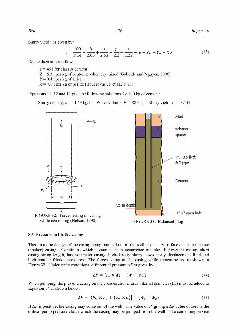
8.3 Pressure to lift the casing There may be danger of the casing being pumped out of the well, especially surface and intermediate (anchor) casing. Conditions which favour such an occurrence include: lightweight casing, short casing string length, large-diameter casing, high-density slurry, low-density displacement fluid and high annular friction pressures. The forces acting on the casing while cementing are as shown in Figure 32. Under static conditions, differential pressure ∆F is given by: ∆ (14)
When pumping, the pressure acting on the cross-sectional area internal diameter (ID) must be added to Equation 14 as shown below: ∆ (15)
If ∆F is positive, the casing may come out of the well. The value of Pp giving a ∆F value of zero is the critical pump pressure above which the casing may be pumped from the well. The cementing service
FIGURE 33: Balanced plug
FIGURE 32: Forces acting on casing
while cementing (Nelson, 1990)
Report 10 127 Bett
crew should ensure that the pump pressure during cement placement does not exceed this value unless the casing is restrained (Nelson, 1990). The case study in Section 8.1.1 for well OW-910 is used to check if there is danger of floating the casing out of the well: 13⅜", 54.50 lb/ft (79.5 daN/m) anchor casing which was set at 294.7 m depth with 1.7 kg/l cement slurry and 1 kg/l water for displacement, the float was set at 284.1 m. Casing external diameter (Do) is 339.7 mm and internal diameter (Di) is 320.4 mm. Under static conditions:
∆F = [1.72 × 103 × 9.81 × 294.68 × π/4 × (339.7/1000)2] - [((294.68 + 11.9) × 79.5) + (1.0 × 103 × 9.81 × (284.12 + 11.9) × π/4 × (320.4/1000)2) + (1.72 × 103 × 9.81 × (294.68 – 284.12) × π/4 × (320.4/1000)2)]
= 178 kN
From the above calculations, it can be seen that the casing will come out of the well even in static conditions. The pump pressure, Pp, to pump the plug as calculated in sub-section D of section 8.1.1 is 18.9 bars. Apart from the positive upward-acting differential force, with the pump pressure acting on the inside of the casing, the additional force due to pump pressure Fp is:
Fp = 152 kN
Therefore, the total force, FT, acting on the casing is:
FT = 330 kN
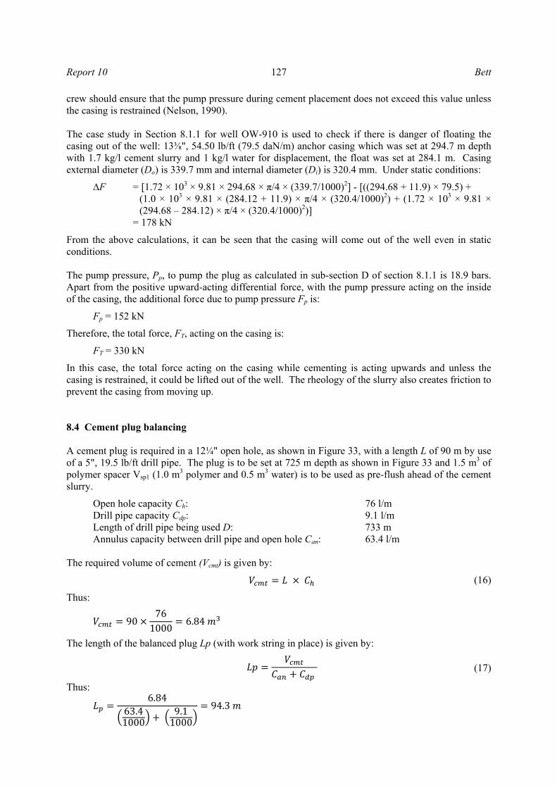
In this case, the total force acting on the casing while cementing is acting upwards and unless the casing is restrained, it could be lifted out of the well. The rheology of the slurry also creates friction to prevent the casing from moving up. 8.4 Cement plug balancing A cement plug is required in a 12¼" open hole, as shown in Figure 33, with a length L of 90 m by use of a 5", 19.5 lb/ft drill pipe. The plug is to be set at 725 m depth as shown in Figure 33 and 1.5 m3 of polymer spacer Vsp1 (1.0 m3 polymer and 0.5 m3 water) is to be used as pre-flush ahead of the cement slurry.
Open hole capacity Ch: 76 l/m Drill pipe capacity Cdp: 9.1 l/m Length of drill pipe being used D: 733 m Annulus capacity between drill pipe and open hole Can: 63.4 l/m
The required volume of cement (Vcmt) is given by:
(16)
Thus: 90 761000 6.84
The length of the balanced plug Lp (with work string in place) is given by:
(17)
Thus: 6.8463.41000 9.11000 94.3
Bett 128 Report 10
The displacement volume (Vd) is given by:
(18)
Thus:
Vd = 5.7 m3 The following should be noted when placing a cement plug:
1. In practice, the cement is frequently slightly under-displaced from the balance point to allow cement slurry to fall while the pipe is being pulled, filling the space that was occupied by the drill pipe.
2. High density spacer (polymer) is pumped ahead of slurry and water spacer is used for displacement.
3. It is good to rotate the drill string while setting the plug to monitor that it is free. 4. There is a risk of cementing tubing getting stuck, especially when the duration of placement is
longer. The use of drill pipe wholly as a cementing tubing is not recommended. In Iceland, 3½" fibreglass cementing pipes are being used at the lower portion of the cementing string which can be drilled out.
9. CONCLUSIONS The main conclusions of this work can be summarized as follows:
• A good and sound cement sheath is achieved when the wellbore is well conditioned before running the casing. It must be ensured that drilling mud cake is removed as much as possible as this ensures proper bonding between the casing and formation.
• The casing string should be well centralized in the wellbore to attain a good cement sheath all around the casing. This will be achieved by ensuring the minimum stand-off of 70% in critical sections of the well.
• Bottom hole circulation temperature is very critical in the design of cement slurry and accurate prediction is necessary as it affects the slurry thickening time and rheology.
• The inclusion of silica flour in the design of cement slurry for geothermal wells ensures longevity of the well since it helps prevent strength retrogression which occurs when cement sheath is exposed to elevated temperatures of more than 120°C.
• The conditions encountered in the wellbore vary from one well to another and therefore pilot tests of cement slurry should be conducted for each cement operation.
• Cementing calculations have to be done cautiously, taking into consideration the experience of the field being drilled, to ensure that correct volumes are pumped to avoid cases of wet shoe that come as a result of over-displacement of cement. This also ensures that pressure limits are not exceeded resulting in burst casings or fractured formations.
ACKNOWLEDGEMENTS I would like to sincerely thank the UNU Geothermal Training Programme Director, Dr. Ingvar B. Fridleifsson and Deputy Director, Mr. Lúdvík S. Georgsson for offering me the opportunity to take part in the programme. I would also like to extend my gratitude to the other UNU-GTP staff: Ms. Thórhildur Ísberg, Mr. Ingimar G. Haraldsson, Ms. Dorthe H. Holme and Mr. Markús A.G. Wilde, for their assistance and support during my stay in Iceland. Many thanks go to Mr. Sverrir Thórhallsson of ÍSOR for good guidance and sharing of valuable knowledge and experience throughout my training. I would like to sincerely thank my supervisors from Mannvit Engineering, Hannes Sverrisson and Hinrik A. Bóasson for their good guidance and technical support during my project report writing. My
Report 10 129 Bett
sincere thanks also go to Arnar B. Árnason for the technical data and support. I would also like to thank my employer, KenGen under the directorship of Mr. Edward Njoroge for granting me the opportunity to attend the training programme. Special thanks go to all my family members, especially my wife and son for their moral support. Above all, I would like to sincerely thank the Almighty God for good care, protection and guidance during the six months training in Iceland.
NOMENCLATURE A = Cross-sectional area (m2); a = Cross-sectional area for casing ID (m2); b = Weight of bentonite per 100 kg of cement (kg); csg = Casing; d = Slurry density (kg/l); Di = Inside diameter (mm); Do = Outside diameter (mm); e = Volume of cement hydration water in relation to cement (l); g = Acceleration due to gravity (9.81 m/s2); H = Fluid column height (m); p = Weight of perlite per 100 kg of cement (kg); Pp = Pumping pressure (N/m2); Ph = Hydrostatic pressure of cement slurry (N/m2); r = Weight of retarder per 100 kg of cement (kg); s = Weight of silica flour per 100 kg of cement (kg); v = Slurry yield (l);
= The cement volume left inside the casing below the float collar = The cement volume in the open hole below the guide shoe
= The cement volume in the annulus between the casing and the hole wall (up to the previous casing shoe).
= The cement volume in the annulus between the casing and the previous casing = The excess added for the uncertainity of the open hole volume
= Total slurry volume,. Wc = Casing weight (N); Wd = Weight of fluid inside casing (N); X = Amount of water per kg of silica (l); Y = Amount of water per kg of silica (l); Z = Amount of swelling water per kg of bentonite (l); ρ = Fluid density (kg/m3).
REFERENCES API, 2009: Hydraulic fracturing operations – well construction and integrity guidelines (1st edition). API Publishing Services, Washington, API guidance document HF1, 32 pp, website: http://www.energyindepth.org/wp-content/uploads/2009/03/API-HF.pdf.
Berndt, M.L., and Philippacopoulos, A.J., 2002: Incorporation of fibres in geothermal well cements. Geothermics, 31, 643-656.
Bourgoyne Jr., A.T., Millheim, K.K., Chenevert, M.E., and Young Jr., F.S., 1991: Applied drilling engineering (2nd printing). Society of Petroleum Engineers, Richardson, Texas, 508 pp.
Bett 130 Report 10
Bush, G., and O'Donnell, K., 2007: Global cementing best practices (Rev. 1). Occidental Oil and Gas Corp., Global Drilling Community, 65 pp.
CaseTech International, Inc., 2010: Cementing methods and equipment. CaseTech International, Inc., website: www.scoretrinidad.com/downhole-tools/CASETECH_BROCHURE.pdf, 53 pp.
Crook, R., 2006: Cementing. Chapter 9 in: Lake, L.W., and Mitchell, R.F. (eds.), Petroleum engineering handbook, vol. II: Drilling engineering. Society of Petroleum Engineers, Richardson, Texas, 369-431.
Drilling and Completion Committee, 1995: Primary and remedial cementing guidelines. Drilling and Completion Committee, Alberta, Canada, 17 pp.
Gabolde, G., and Nguyen, J.P., 2006: Drilling data handbook (8th edition). IFP publications, Editions Technip, 541 pp.
Gaurina-Medimurec, N., Matanovic, D., and Krklec, G., 1994: Cement slurries for geothermal wells cementing. Rudarsko-Geolosko-Naftni Zbornik, 6, 127-134.
Hernández, R., and Bour, D., 2010: Reverse-circulation method and durable cements provide effective well construction: A proven technology. Proceedings of the 35th Workshop on Geothermal Reservoir Engineering, Stanford University, Stanford, California, 4 pp.
Heriot-Watt University, 2010: Drilling engineering. Heriot-Watt University, Depm. of Petrol. Eng., website: www.4shared.com/document/8oA1j29G/Heriot-Watt_University_-_Drill.html, 539 pp.
Hole, H.M., 2008: Geothermal well cementing. Petroleum Engineering Summer School, Dubrovnik, workshop 26, 6 pp.
Iverson, B., Maxson, J., and Bour, D., 2010: Strength retrogression in cements under high-temperature conditions. Proceedings of the 35th Workshop on Geothermal Reservoir Engineering, Stanford University, Stanford, California, 8 pp.
Kabinoff, K.B., Ekstrand, B.B., Shultz, S., Tilghman, S.E., and Fuller, D., 1992: Determining accurate bottomhole circulating temperature for optimum cement slurry design. Society of Petroleum Engineers Western Regional Meeting, Bakersfield, California, 8 pp.
Kutasov, I.M., and Kagan, M., 2002: Procedures to correct temperatures for deep offshore well. Oil and Gas Journal, 100-49, 56-61.
Nelson, E.B. (ed.), 1990: Well cementing. Schlumberger Educational Services, Texas, 487 pp.
Niggemann, K., Samuel, A., Morriss, A.V., and Hernández, R., 2010: Foamed cementing geothermal 13 3/8" intermediate casing. Halliburton, NGP 61-22, 11 pp.
Ogbonna, F.J., 2009: The secondary effects of lignosulfonate cement retarder on cement slurry properties. ARPN J. Eng. & Appl. Sci., 4-9, 7 pp.
Rabia, H., 1985: Oilwell drilling engineering: principles and practice. Graham & Trotman, London, 322 pp.
Rabia, H., 2001: Well engineering and construction. Entrac Consulting, 789 pp.
Shyrock, S.H., and Smith, D.K., 1982: Methods of combating lost circulation during drilling and casing cementing. In: Geothermal Resources Council Special Report No. 12, 67-80.
Thórhallson, S., 2010: Geothermal drilling technology. UNU-GTP, Iceland, unpublished lecture notes, 41 pp.
Weatherford (publ.), 1986: Cementing program. Weatherford.