georgia dot pedestrian and streetscape guide
TRANSCRIPT


TABLE OF CONTENTS
IntroductionWhy a Pedestrian and Streetscape Guide? 1Who Will Use This Guide? 2What is the Focus? 3References and Other Resources 3Acknowledgments 3
How to Use this GuideHow Should the Information in This Guide Be Used? 5Relationship to Other Guidelines and Standards 5Permission to Reproduce and Copy 6Where Can You Find the Information You Need in This Guide? 6
About PedestriansPedestrians Defined 9Pedestrian Safety 9Pedestrian Needs 11Levels of Use and Travel Characteristics 16
Design Toolkit
Toolkit 1 — General Design GuidelinesPedestrian Facilities Defined 22The Importance of Good Design for Pedestrians 22The “Bigger Picture” — Creating Pedestrian-Friendly Communities 24Creating a Continuous Pedestrian System 26Special Pedestrian-Oriented Districts and Areas 26Creating an Effective Pedestrian System 27Pedestrian-Friendly Streets 27Other Sources of Information 29
Toolkit 2 — AccessibilityUnderstanding the American with Disabilities Act (ADA) 32Designing for People With Disabilities 33Designing for Older Adults 33Pedestrian Access Routes 33Eliminating Barriers and Obstacles 35Widths and Clearances 35Passing and Resting Areas 36Difference Between Site Development and Site Development Requirements 36
I

PEDESTRIAN AND STREETSCAPE GUIDE
Sidewalk Curb Ramps 38Accessibility Across Driveways 41Surfacing 42Textural and Visual Cues 43Accessible Pedestrian Signals (APS) 46Crosswalks 53Medians and Pedestrian Refuge Islands 54Signing and Other Communication Aids 54Other Sources of Information 56
Toolkit 3 — Children and School ZonesSpecial Considerations Related to Children 58Improving Student Pedestrian Safety -A Cooperatative Process 58School Related Pedestrian Improvements 59The School as a Community Focal Point 60Pedestrian-Friendly Schools and School Zones 60Traffic Control and Crossings Near Schools 65School Walk Routes and Safety Programs 72Education Tools and Programs for Child Safety 72Ongoing Maintenance 73Other Sources of Information 73
Toolkit 4 — Trail and PathwaysTrails and Paths Across Multiple Jurisdictions 75Regional Connectivity 75Accessibility of Trails and Paths 76Special Considerations for Shared Use Paths 77Recommended Dimensions 80Paving and Surfacing 82Grades, Cross Slopes, and Drainage 83Shoulders, Side Slopes, and Railings 83Connections and Crossings 84Managing Motor Vehicle Access 84Vegetation and Landscaping 85Seasonal and Nighttime Use 86Maintenance 86Other Sources of Information 86
Toolkit 5 — Sidewalks and WalkwaysDetermining When and Where Sidewalks and Walkways are Needed 90Sidewalks and Walkways in Various Settings 91Descriptions and Comparisons of Sidewalks and Walkways 92Location — Both Sides Versus One Side 93Accessibility 94Recommended Dimensions 94Passing, Waiting, and Resting Areas 95
II

TABLE OF CONTENT S
Grades, Cross Slope, and Drainage 95Side Slopes, Railings, and Walls 96Surfacing 97Street Separation and Edge Treatments 98Street Furnishings, Utilities, and Related Clearances 103Landscaping and Street Trees 105Lighting 105Signing 106Historic Districts 106Sidewalks in Business Districts and Downtowns 107Shoulders as Walkways in Rural Areas 108Bicycles on Sidewalks 110Street Design Considerations 111Maintenance 115Other Sources of Information 116
Toolkit 6 — IntersectionsEffects of Pedestrian Improvements on Vehicle Capacity 120Common Design Practices for Pedestrian Crossings at Intersections 120Crosswalk Use 120Minimizing the Crossing Distances at Intersections 129Minimizing Pedestrian/Motor Vehicle Conflicts 135Other Sources of Information 145
Toolkit 7 — CrossingsDetermining the Need for Mid-Block Crossings 148Mid-Block Crossing Design 149Railroad Crossings 158Grade Separated Crossings 159Multi-Use Trail Intersections and Crossings 162Boardwalks and Trestles 162Other Sources of Information 163
Toolkit 8 — Traffic CalmingWhy Is Traffic Calming Used? 165The Traffic Management Approach 166Traffic Calming Techniques 166Traffic Calming on Arterial Streets 174Administration of a Traffic Calming Program 175Other Sources of Information 176
Toolkit 9 — Pedestrian Access to TransitTransit Compatible Design 180Improving Transit Facilities for Pedestrians 180Transit Stops and Bus Pullouts 183High Capacity Right-of-Way Transit 184
III

PEDESTRIAN AND STREETSCAPE GUIDE
Transit Centers 186Park-and-Ride Facilities 186Transit Malls 197Transit-Oriented Development 187Coordination Between Agencies 188Other Sources of Information 188
Toolkit 10 — Site Design for PedestriansThinking About Pedestrians as Part of Site Development 191Pedestrian-Friendly Site Design 192Building Location and Design 193On-Site Circulation and Parking 194Walkways and Accessible Routes 196Site Access and Driveway Design 197Landscaping and Furnishings 199Ramps, Handrails, Stairways, and Steps 200Sites Used Exclusively by Pedestrians 202Play Streets 204Strategy for Increasing Pedestrian Travel — Mixed-Use Site Development 204Other Sources of Information 205
Toolkit 11 — Safety in Work ZonesProtective Barriers 208Covered Walkways 208Sidewalk Closure During Construction 208Intersections and Crossings Near Work Zones 210Accessibility in the Work Zone 211Maintenance 211Other Sources of Information 212
Resource Guide 213
IV
TABLE OF CONTENT S
Table 1 - GDOT’s Bicycle and Pedestrian Plan Goals 2Tble 2 - Anticipated Guide Users 2Table 3 - “Design” Focus 3Table 4 - Pedestrian Facilities 3Table 5 - Other Documents to Review for Pedestrian and Streetscape Guide 6Table 6 - Common Characteristics of Pedestrian Collisions 10Table 7 - Some Important Needs of Pedestrians 12Table 8 - Common Pedestrian Characteristics by Age Group 14Table 9 - Aids to Older Pedestrians 15Table 10 - Aids to Pedestrians With Disabilities 15Table 11 - Why Urban Areas Receive High Pedestrian Use 17Table 12 - Typical Types of Pedestrian Trips 17Table 13 - Pedestrian Trip Facts 17Table 14 - Common Reasons for Low Levels of Pedestrian Travel 18Table 15 - Ask the Following Questions 20Table 16 - Pedestrian Facilities 22Table 17 - Typical Policies for Encouraging Pedestrian Travel 23Table 18 - Common Characteristics of Pedestrian Friendly Communities 24Table 19 - Typical Elements of Pedestrian-Friendly Streets 27Table 20 - Pedestrian Access Route 33Table 21 - Important Things to Remember About Curb Ramps 41Table 22 - Most Common Types of Pedestrian/Motor Vehicle Collisions 57Table 23 - Some Special Limitations of Children Aged 5 to 9 58Table 24 - Process for Improving Student Pedestrian Safety 59Table 25 - The School as a Community Focal Point 60Table 26 - Elements of Good School Site Design 61Table 27 - Roadside Pedestrian Improvements Along School Walk Routes 62Table 28 - Potential Traffic Control and Crossing Treatments Near Schools 66Table 29 - When to Utilize Adult Crossing Guards 69Table 30 - Primary Functions of Student Safety Patrollers 69Table 31 - Procedures for Developing School Walk Routes 72Table 32 - Delineation/Separation Treatments for Shared Use Paths 79Table 33 - Separation Treatments for Shared Use Path Next to Roadway 80Table 34 - Recommended Dimensions for Trails and Paths 81Table 35 - Priorities for Pedestrians Traveling Along Streets 89Table 36 - ITE Criteria for Determining Pedestrian Safety Deficiencies 90Table 37 - Guidelines for New Sidewalk Installation 93Table 38 - Recommended Dimensions for Sidewalks and Walkways 95Table 39 - Advantages and Disadvantages of Planting Buffers 98Table 40 - Recommendations for Walking Shoulders 110Table 41 - Access Management 113Table 42 - Benefits and Disadvantages of One-Way Streets 114Table 43 - Maintenance Recommendations for Sidewalks 115Table 44 - Basic Principles of Intersection Design to Accommodate Pedestrians 121Table 45 - Guidelines for Determining the Need for Marked Crosswalks 124Table 46 - Advantages and Disadvantages of Crosswalk Marking Patterns 127
Tables
V

PEDESTRIAN AND STREETSCAPE GUIDE
Figure 1 - Fatalities Based on Speed of Vehicle 10Figure 2 - Thinking and Stopping Distances Related to Speed of Travel 11Figure 3 - Human Dimensions When Walking and Sitting 13Figure 4 - Passing on a 6-foot Sidewalk 13Figure 5 - Spatial Needs for Pedestrians 13Figure 6 - Spatial Bubbles 14Figure 7 - Spatial Dimensions for People With Disabilities 15Figure 8 - Creating an Effective Pedestrian System 28Figure 9 - Accessible Site Design 34Figure 10 - Accessible Passing Area 36Figure 11 - Accessible Ramped Pathway With Landings 37Figure 12 - Accessible Curb Ramp Design Detail - Type A 39Figure 13 - Accessible Curb Ramp Design Detail - Type B and C 39Figure 14 - Sidewalk Curb Ramps at Intersections 40Figure 15 - Traditional Driveway Design 41Figure 16 - Driveway With Wide Sidewalks 41Figure 17 - Driveway With Planting Strips 42Figure 18 - Driveway With Sidewalk Behind 42Figure 19 - Driveway With Dipped Sidewalk 42Figure 20 - Detectable Warning At Multiuse Path 44Figure 21 - Detectable Warning At Railroad Crossing 44Figure 22 - Refuge Island 44Figure 23 - Detectable Warning At Curb Ramp 45Figure 24 - Detectable Warning At Transition Ramp 45Figure 25 - Detectable Warning At Shared Ramp 45Figure 26 - Detectable Warning At Blended Curb 45Figure 27 - O Dome Spacing 45Figure 28 - N Dome Section 45Figure 29 - P Dome Alignment 46Figure 30 - Curb Ramp APS Zones 49Figure 31 - Transition Ramp APS Zones 49
Table 47- Benefits and Disadvantages of Shortening Curb Radii 131Table 48 - Locations Where Refuge Islands are Most Beneficial 132Table 49 - Measures to Improve the Effectiveness of Push Buttons 138Table 50 - Crossing Distances, Speeds, and Time 139Table 51 - Suggestions for Reducing Turning Conflicts 140Table 52 - Design Guidelines for Medians and Refuge Islands 154Table 53 - Common Residential Traffic Management Program Actions 168Table 54 - Common Types of Traffic Calming Methods 168Table 55 - Approaches for Administrating a Traffic Calming Program 177Table 56 - Low Cost Improvements to Increase Pedestrian Access to Transit 183Table 57 - Pedestrian-Friendly Site Design Checklist 192Table 58 - ADA Requirements for Ramps 200Table 59 - Checklist for Successful Mixed Use Site Developments 206Table 60 - Considerations for Pedestrian Safety in Work Zones 208Table 61 - Work Zone Maintenance 211
Figures
VI

TABLE OF CONTENT S
Figure 32 - Shared Curb Ramp APS Zones 49Figure 33 - Tactile Arrow 49Figure 34 - APS Universal Symbol 49Figure 35 - School Site Design 62Figure 36 - Sidewalk 63Figure 37 Widened Shoulder 63Figure 38 - Typical Bus Stop Design for Urban Location 64Figure 39 - Typical Bus Stop Design for Rural Location 64Figure 40 - Typical Signing for School Area Traffic 70Figure 41 - School Signs 71Figure 42 - One Lane School Marking 72Figure 43 - Accessible Trail/Path 76Figure 44 - Universal Levels of Accessibility Signs 77Figure 45 - Multi-Use Shared Use Path Striping 78Figure 46 - Shared Use Path 78Figure 47 -Paved Path With Separated Soft Surface Trail 79Figure 48 - Pathway Separation From Roadway 80Figure 49 - Paved Pedestrian-Only Trail 82Figure 50 -Unpaved Pedestrian-Only Trail 82Figure 51 - Unpaved Shared Use Trail 82Figure 52 - Shared Use Path Pavement Cross Sections 83Figure 53 - Paths Requiring Railings 84Figure 54 - Thickened-Edge Pavement Design 85Figure 55 - Bollard Spacing 85Figure 56 - Split Pathway Entrance 86Figure 57 - Root Barrier 87Figure 58 - Waiting and Resting Areas 95Figure 59 - Wall Design Treatments 96Figure 60 - Planting Buffer Between Sidewalk and Street 98Figure 61 - Planting Strips Provided as Area for Signs and Utilities 99Figure 62 - Speed Design/Posted Speed < 35 mph 100Figure 63 - Straight Walkway 101Figure 64 - Meandering Walkway 101Figure 65 - Sidewalk Separated by a Swale 101Figure 66 - Sidewalk Adjacent to Curb and Gutter 102Figure 67 - Vertical Curb Adjacent to a Planting Strip 102Figure 68 - Sidewalk With Rolled Curb 102Figure 69 - Bike Lane as Buffer Between Pedestrians and Motor Vehicles 103Figure 70 - Clearances for Sidewalks and Walkways 104Figure 71 - Pedestrian Travel Way, Clear of Obstructions 104Figure 72 - Urban Streetside Zones 107Figure 73 - Shy Distance Between Building and Walkway 107Figure 74 - Shoulder Walkway 109Figure 75 - On-Street Parking as a Buffer Between Street and Pedestrian s 111Figure 76 - Parking Overhang 112Figure 77 - Access Management 113Figure 78 - Guidelines for the Installation of Marked Crosswalks 122Figure 79 - Marked and Unmarked Crosswalks at Intersection 122Figure 80 - Clear Travel Area for Pedestrians at Intersection Corners 124
VII

PEDESTRIAN AND STREETSCAPE GUIDE
Figure 81 - GDOT Crosswalk and Location Details 126Figure 82 - Sign to Accompany Advance Yield Bar 128Figure 83 - Crossing Sign 129Figure 84 - Reduced Crossing Distance With Reduced Curb Radius 130Figure 85 - Reduced Curb Radii at One-Way Intersection 130Figure 86 - Elongated Refuge Island at Right-Turn Slip Lane 131Figure 87 - Right-Turn Slip Lane and Refuge Island 133Figure 88 - Median/Refuge Island at an Intersection 134Figure 89 - Typical Curb Extension Design 134Figure 90 - Typical Curb Bulb-Out Design 134Figure 91 - Curb Bulb-Outs and Extensios 134Figure 92 - Visibility at Intersection Corners 135Figure 93 - Recommended Parking Setback for Sight Distance 136Figure 94 - Pedestrian Indication Sequence 137Figure 95 - Modern Roundabout Design 142Figure 96 - Traffic Calming Circle 143Figure 97 - Special Paving 144Figure 98 - Typical Mid-Block Crossing 148Figure 99 - Mid-Block Crossing of Two-Lane Arterial 151Figure 100 - Mid-Block Crossing of Five-Lane Arterial With Existing Median 153Figure 101 - GDOT Soft Sandwich 155Figure 102 - Portable Pedestrian Flags 157Figure 103 - Typical Geometries of Overhead Crossings 161Figure 104 - Typical Geometries of Underpasses 163Figure 105 - Traffic Management Approach — Solving the Problem 167Figure 106 - Recommended Traffic Calming Circle Design 171Figure 107 - Narrowed Street 171Figure 108 - Chicanes 172Figure 109 - Curb Bulb-Outs and Extensions 173Figure 110 - Raised Crosswalk/Speed Table 174Figure 111 - Transit Compatible Objectives 180Figure 112 - Widened Sidewalk in Bus Loading Area 181Figure 113 - Typical Bus Stop Cross-Section 181Figure 114 - Bus Shelters and Covered Structures 182Figure 115 - Same Corner Bus Stop Locations 184Figure 116 - Retro-fitted Shopping Center for Pedestrian Access 193Figure 117 - Access to Transit 195Figure 118 - Shared Parking Lot 195Figure 119 - Accessible Building Entrance 196Figure 120 - Covered Walkways 197Figure 121 - Driveway Design Comparisons 198Figure 122 - Wide Planting Areas at Driveway 199Figure 123 - Handrail Detail 201Figure 124 - Pedestrian Plaza 202Figure 125 - Landing Placement for Stairways 203Figure 126 - Stair/Step Nosing Design 203Figure 127 - Mixed-Use Site Development Concept 205Figure 128 - Crosswalk Closures and Pedestrian Detours 209Figure 129 - Temporary Pedestrian Routes 210
VIII

INTRODUCTION
1
Why a Pedestrian andStreetscape Guide?As Georgia’s population continues to grow, westrive to create livable communities that offer adiversity of transportation alternatives includingconvenient, reliable, safe, efficient, and attractivepedestrian facilities.
Most of us are pedestrians at some point each day,and for some of us, especially children, walking isa primary mode of transportation. Whether wewalk several miles a day, use a wheelchair to getfrom our office to the bus stop, ride a skateboard
through the park, or simply walk across theparking lot from our car to the grocery store, all ofus have a need for well-designed and properlyfunctioning pedestrian facilities.
Georgia State Department of Transportation’s(GDOT) mission states that “(We) are committedto a safe, efficient, and sustainable transportationsystem for all users.” Through this mission,GDOT created the Bicycle and Pedestrian Plan(1995) that defines several goals for increasingpedestrian travel throughout the state. These areshown in Table 1.
The Federal Highway Administration (FHWA)has a national policy addressing pedestrianfacilities into the transportation infrastructure.This statement specifies “bicycling and walkingfacilities will be incorporated into alltransportation projects unless exceptionalcircumstances exist.” (FHWA 2000). Thisprinciple should be applied to federally fundedstate and local transportation projects. To ensurepedestrian facilities exist at the local level, theyshould be included in city capitol improvementplans.
GDOT began the guide process by creating aStatewide Bicycle and Pedestrian AdvisoryCommittee. This guide will help achieve many ofthe goals in GDOT’s Bicycle and Pedestrian Plancreated in 1995.
Users should be aware of some limitations whenapplying the recommendations in this document.Some recommendations are provided as “bestpractices” and don’t necessarily conform toGDOT standards and policies. Use of features orelements that do not conform to GDOT policies
Increasing pedestrian travel and safety are objectivesof Georgia’s Transportation Plan.

2 PEDESTRIAN AND STREETSCAPE GUIDE
GDOT’s Bicycle and PedestrianPlan Goals
• Promote bicycling and walking as mobility
options in urban and rural areas of the state.
• Develop a transportation network of primary
bicycle routes throughout the state to
provide connectivity for intrastate and
interstate bicycle travel.
• Promote establishment of U.S. numbered
bicycle routes in Georgia as part of a
national network of bicycle routes.
• Encourage economic development
opportunities that enhance bicycle and
pedestrian mobility.
• Promote non-motorized transportation as a
means of congestion mitigation.
• Promote non-motorized transportation as an
environmentally friendly means of mobility.
• Promote connectivity of non-motorized
facilities with other modes of transportation.
Table 1
and/or standards should only be done afterconsultation with GDOT. For example,placement of trees in clear zone areas may beacceptable for locally funded improvements, butnot acceptable per GDOT standards, whichalways apply when the project is funded throughGDOT. If newaccessibility standards are enactedby the Access Board, or any federal legislation, theapplication of these guidelines should notcontradict or be inconsistent with those newfederal or state standards.
Who Will Use This Guide?The design guidelines provided in this guide willassist GDOT, cities, counties, private developers,design professionals, and others in designing,constructing, and maintaining pedestrian facilitiesin a variety of settings, including urban, suburban
Table 2
Primary Audience• Traffic and transportation engineers
• Site development and building permit
review staff
• Planners and designers, including architects,
civil engineers, landscape architects, urban
designers, and other design professionals
• Developers
Others Who Might Findthe Guide Helpful• School districts
• Neighborhood councils and planning
committees
• Metropolitan planning organizations
• Central business district planning
organizations/business people
• Small towns
• Officials and politicians
• Special campaigns and programs
• Citizen advocates
Georgia strives to provide a safe pedestrianenvironment for all its citizens, especially children.
Anticipated Guide Users

3INTRODUCTION
and law enforcement also contribute to improvingour communities for pedestrians. Some basicprinciples related to planning for pedestrians areprovided in this handbook, but the overall intentis to encourage good design practices.
References and OtherResourcesThe technical information contained in this guidewas compiled from numerous sources. TheResource Guide at the end of this documentprovides a comprehensive list of sources forinformation related to pedestrian planning anddesign, including sources referenced for thisdocument. In addition to the Resource Guide,readers interested in finding additionalinformation related to specific types of pedestrianfacilities will find a list of relevant sources ofinformation at the end of each section of thedesign toolkit. The Resource Guide also listssources of information related to pedestrianplanning, education, and enforcement.
When no specific source is referenced for graphics,figures, and tables in this document, drawingswere created and/or other information wascompiled especially for use in the Pedestrian andStreetscape Guide. In some cases, otherdocuments or sources of information may havebeen researched and specifically adapted for thisguide based on input from GDOT or the advisorygroup and other technical experts involved.
AcknowledgmentsFunding for this report was provided to theGeorgia Department of Transportation withfederal funds from the U.S. Department ofTransportation.
“Design” Focus
The primary focus of this guide is to
encourage good planning, design, and
engineering practices related to pedestrian
facilities. The guide also addresses a few
important construction, ongoing maintenance,
and operational aspects related to
pedestrian facilities.
Table 3
Pedestrian Facilities
For the purposes of this guide, pedestrian and
streetscape facilities include:
Sidewalks, trails, curb ramps, grade separated
crossings, wide shoulders, traffic calming and
control devices and other technology, design
features, and strategies intended to encourage
pedestrian travel.
Table 4
and rural communities throughout Georgia. Theprimary audience of the guide will betransportation design practitioners, includingthose listed in Table 2.
What is the Focus?The focus of this guide is on design of pedestrianand streetscape facilities (see Tables 3 and 4), butgood design is only one component of a successfulpedestrian facility. Conscientious planning,effective education programs, and consistent safety
4 PEDESTRIAN AND STREETSCAPE GUIDE
Sponsoring Agencies and Organizations• Georgia Department of Transportation
• GDOT’s Internal Bicycle and PedestrianTaskforce
• State Bicycle and Pedestrian AdvisoryCommittee
• Pedestrians Educating Drivers on Safety (PEDS)
Consultant Team• Otak, Inc.
Mandi Roberts, Project Manager
in association with:• Arcadis
• Janet Barlow
HOW TO USETHIS GUIDE
5
How Should the Informationin This Guide Be Used?The information presented in this guide shouldnot be interpreted as standards, specifications,requirements, or regulations, but rather asguidelines.
The guidelines included in this guide apply tonormal situations encountered during projectdevelopment. Unique design problemssometimes require flexibility in design solutions.Other available design information and allapplicable federal, state, and local requirementsshould be reviewed as part of the project design.Some elements of the guide may not beappropriate for major highways and arterial routesor may not be possible on existing right-of-way,but some parts of the guide should always beconsidered and implemented where ever feasible.
The information presented in this guide may notsolve all problems associated with pedestrian
travel, but it provides a “first step” in establishinga consistent set of statewide guidelines for designof pedestrian facilities. The guide can also beused as a tool to build consensus on sometimesdiffering approaches to design.
The guidelines in this guide are often presented interms of “desirable” and “minimum” dimensions orrecommendations. These recommendationsshould be applied with professional judgement toachieve design solutions that are specificallytailored to the circumstances encountered. Forexample, if a sidewalk receives a high amount ofuse, the project designer or local design reviewermay elect to apply the “desirable” dimension overthe “minimum” for the sidewalk width.
Relationship to OtherGuidelines and StandardsCities and counties may already have adoptedstandards related to design of pedestrian facilities.In that case, the guidelines can be referenced as asupplement to local standards. When nostandards have been adopted by federal, state, orlocal agencies, these guidelines and otherdocuments can provide useful direction to designpractitioners. Eventually, local agencies mayamend their current design standards toincorporate all or portions of these guidelines.
Pedestrian facilities should be designed and builtin accordance with existing federal, state, andlocal standards as applicable. In some situations,the current standard may not be achievable due togeometric, environmental, or other constraints.In these circumstances, variances from thestandard may be acceptable; however, a facilityshould not typically be built to less than the
Georgia pedestrians live, work, and play in a widevariety of settings, and design of pedestrian facilitiesneeds to be adaptable to these settings.

6 PEDESTRIAN AND STREETSCAPE GUIDE
minimum standards described. Deviations fromstandards should be documented and justifiedthrough special studies. Table 5 lists severaldocuments that include other design standardsand guidelines related to pedestrians.
Permission to Reproduceand CopyPermission is granted by the authors and sponsorsof this guide to all other parties to make anddistribute copies of all or portions of theinformation in this guide, without limitations, inaccordance with the “fair use” provisions of theUnited States Copyright Act.
Where Can You Find theInformation You Need inThis Guide?
About PedestriansRefer to the next section of this guide, AboutPedestrians, for information about the needs andcharacteristics of pedestrians and factors that affectpedestrian travel.
Design ToolkitThe Design Toolkit provides recommendationsunder 11 topics. A directory of the toolkit topicsis provided on the first page of the Design Toolkitfor easy reference. Toolkit 1 — General DesignGuidelines, provides a general overview of designconsiderations related to pedestrians and creatingpedestrian friendly communities. Toolkit 2 —Accessibility, provides recommendations andguidelines related to accessible design andcompliance with the Americans with Disabilities
Table 5
Other Documents to Review forPedestrian and Streetscape Guide
• Local design standards, zoning codes and
development codes
• Americans with Disabilities Act (ADA) Federal
Requirements
• Manual on Uniform Traffic Control Devices,
Federal Highway Administration, USDOT
• A Policy on Geometric Design of Highways and
Streets, American Association of State
Highway and Transportation Officials
(AASHTO)
• Uniform Building Code (UBC), International
Conference of Building Officials, and/or
locally adopted building code
• Design and Safety of Pedestrian Facilities, ITE
• Guide for Planning, Design, and Operation of
Pedestrian Facilities, AASHTO
• Guide for the Development of Bicycle Facilities,
AASHTO
Note: This is only a partial list and does not include allavailable resources. See the Resource Guide for other relevantpublications
Look for the BoxesImportant and helpful information is
highlighted in boxes like this one, throughout
the guide.
This guide provides recommendations for a variety ofpedestrian facilities.

7HOW TO USE THIS GUIDE
Act (ADA). The remaining toolkit sections focuson more specific areas of pedestrian facility design.
Resource GuideLook in the Resource Guide near the end of thisguide for a comprehensive list of sources related toplanning and design of pedestrian facilities.Relevant sources of information related topedestrian facilities addressed are also listed at theend of each toolkit section.
Sometimes, there's more than “one-way” to find thebest solution for design of pedestrian and streetscapefacilities.

ABOUTPEDESTRIANS
9
Understanding the needs and characteristics ofpedestrians and factors that affect pedestrian travelis important when designing pedestrian facilities.This part of the guide describes the many types ofpedestrians and provides information aboutpedestrian safety and current research on levels ofpedestrian travel.
Pedestrians DefinedEvery trip begins and ends as a pedestrian trip —whether walking to a bus stop or across a parkinglot to your car.
Georgia State law defines a Pedestrian as:“Any person who is afoot” (GLC 40-1-1),
By state definition, rollerskaters, in-line skaters,and skateboarders are also pedestrians. Wheelchairusers are also considered pedestrians.
Pedestrian SafetyAnalysis of pedestrian/motor vehicle collisions canhelp establish engineering, education, andenforcement solutions. Most reported pedestrianinjuries are a result of collisions with motorvehicles. According to Mean Streets, a projectconducted by the Surface Transportation PolicyGroup, there were 356 pedestrian fatalities causedby motor vehicles in the state of Georgia in 1997and 1998. Pedestrians accounted for 11.5percent of all persons killed in traffic-relatedcollisions. The report also cited that MetroAtlanta is the second most dangerousmetropolitan area for pedestrians in the US, onlybehind Tampa, Florida.
According to the National Highway Traffic SafetyAdministration (NHTSA), 4,906 pedestrians inthe United States were killed in traffic crashes in1999. 85,000 pedestrians were injured in trafficcrashes. One-fourth of those fatalities wherechildren between the ages of 5-9. Most fatalitiesoccurred in urban areas, at non-intersectionlocations, at night. According to the InsuranceInstitute for Highway Safety “Pedestrians are thesecond largest category of motor vehicle deaths,after occupants.” Overall, pedestrian fatality ratesare declining. In 1975, pedestrian fatalitiesaccounted for 17 percent of all motor vehicleaccidents and in 2000, pedestrian fatalitiesaccounted for 11 percent. This is likely due toseveral things, including the increased focus onimproving pedestrian safety and good design forpedestrians and the decline in exposure,particularly by high risk groups. According toMean Streets, American children now walk 37percent less than they did twenty years ago. Eventhough fatality rates are declining, pedestrian
Every trip begins and ends as a pedestrian trip.

10 PEDESTRIAN AND STREETSCAPE GUIDE
safety is still an ongoing and important concern.Common characteristics of pedestrian collisionsare listed in Table 6.
Vehicle speed is a significant factor in causingfatalities as a result of pedestrian collisions. Thefaster a motorist drives, the more likely injuries toa person on foot will result in death. The chart inFigure 1 illustrates the rate of death that occurs incorrelation to the speed of a vehicle involved.
As the figure shows, when collisions occur withthe vehicle travelling at a speed of 40 mph, 85percent of pedestrians are killed, compared to adeath rate of 45 percent at a vehicle speed of 30mph, and only 5 percent at a vehicle speed of 20mph. The ability to stop in time for crossingpedestrians also significantly decreases as vehiclespeed increases, as shown in Figure 2.
Identifying areas where most pedestrian injuriesand fatalities occur, is a start to improving
Common Characteristics of Pedestrian Collisions
• Driver inattention
• Struck by vehicle while crossing at an intersection (50 percent of all collisions)
• Struck by vehicle while crossing mid-block (33 percent of all collisions)
• Struck from behind while walking along the roadway in the same direction as traffic (particularly in rural
areas)
• Motorist exceeding safe speed (contributes to most pedestrian deaths)
• Darting out into the street at mid-block (most common type of pedestrian collision for children)
• Vehicles backing up (difficult to see children and others walking behind)
• Collisions in urban areas (80 percent of all collisions)
Source: Pedestrian and Bicycle Crash Types of the Early 1990s; (Snyder, Knoblauch, Moore, and Schmitz; Cross and Fisher)
Table 6
Figure 1
Source: Walk Tall: A Citizen’s Guide to Walkable Communities
Fatalities Based on Speed of Vehicle

11ABOUT PEDESTRIANS
pedestrian safety. High risk areas can be mappedand analyzed using several different techniques,including Geographic Information Systems (GIS)software. Once risk areas are identified,improving the pedestrian environment in theseareas should then be a high priority.
Children and Older AdultsThe pedestrians most likely to be involved incollisions are also the ones who most rely onpedestrian travel for transportation — childrenand older adults. In Georgia, children and youngadults age 5 to 19 constitute only 7.5 percent ofthe population; yet between 1997 and 1998, thisgroup accounted for 13.20 percent of allpedestrian fatalities in Georgia (Mean Streets2000, Surface Transportation Policy Group).According to NHTSA, 24 percent of all childrenbetween the ages of 5 and 9 who were killed intraffic crashes were pedestrians. 5 to 9 year-oldmales are most at risk for pedestrian injuries orfatalities. This group is the most likely to dart-out in front of traffic.
People over age 65 represented 11.9 percent ofthe national population; yet accounted for 18percent of all pedestrian deaths during that sameyear (Traffic Safety Facts 1999, NHTSA ). Thedeath rate for people over 65 was higher than anyother age group. People over 65 are two to fourtimes more likely to die when involved in apedestrian-motor vehicle collision. Older adultsare particularly more vulnerable while crossing thestreet, since they need more time to cross.
Pedestrian NeedsIn order to successfully design pedestrianfacilities, we must recognize that pedestrian needsare wide-ranging, and our design approach mustbe flexible to meet the diversity of needs.
For some of Georgia’s population, especially inmetro Atlanta, pedestrian travel is the primarymode of transportation. Citizens in this segmentof the population include those who do not use amotor vehicle including some older adults,children and young adults, people who walk tothe bus or train, people with certain disabilities,and people who can’t afford to own cars. There
Figure 2
Thinking and Stopping Distances Related to Speed of Travel(Under Optimum Conditions)
Note: Required stopping sight distances may differ from these distances. Refer to AASHTO.Source: Walk Tall: A Citizen’s Guide to Walkable Communities; Killing Speed and Saving Lives

12 PEDESTRIAN AND STREETSCAPE GUIDE
provide information on acceptable walkingdistances:
• Traditionally, planners strive to locatecommunity facilities, neighborhood parks, andother popular pedestrian origins anddestinations no more than one-quarter milefrom the origin of most pedestrian travel.
• Site designers typically use 300 feet as themaximum distance from parking and sitepedestrian circulation to building entrances.Street crossings are typically most effective whenlocated approximately 300 to 600 feet apart inareas heavily used by pedestrians.
• Pedestrians can be expected to travel about1,000 to 2,000 feet to a major transit station —about 750 feet for mobility impaired. Mostpedestrians will walk farther if the transit stationserves higher frequency transportation options,such as light rail.
Spatial NeedsFigure 3 illustrates approximate humandimensions when walking and sitting.
are also many others who choose pedestrian travelas their primary mode of transportation.
Recognizing why people do not walk in the firstplace, is an important step in determining theirneeds. Certain circumstances such as insufficientinfrastructure, physical barriers (rivers orfreeways), lack of curb ramps, major roadseparation from commercial districts, and longblock lengths, which prevent street crossings, aresome reasons why people do not walk. Accordingto the University of North Carolina HighwaySafety Research Center, a high correlation existsbetween communities who meet the needs of thepedestrian and an increased level of pedestriantravel. In communities that do not provideadequate pedestrian facilities, fewer people walkand those who do are in far more danger ofpedestrian injuries and fatalities.
Another common obstacle in designing pedestrianfacilities is assuming that one standard can beapplied to fit an “average” population. For example,the speed that pedestrians travel can vary greatly,yet pedestrian signals are often timed for averagewalking speeds of 3 to 4 mph. Children, olderadults, and people with certain disabilities typicallytravel at a much lower walking speed of 2 mph.
Pedestrian needs are diverse, but one thingremains the same—pedestrians need a safe,interesting, and inviting environment. Sometypical pedestrian needs are listed in Table 7.
Acceptable Walking DistancesAcceptable walking distances will vary dependingon geography, climate conditions, and land usepatterns. The distance pedestrians will travel isalso influenced by the weather, the time of day,demographics, the purpose of their trip, andmany other factors. Most people will walk longerdistances for recreational purposes, but prefer towalk shorter distances when they are commutingor in a hurry, such as from the bus stop or transitstation to their office. The following guidelines
Table 7
Some Important Needsof Pedestrians
• Safe streets and walking areas
• Convenience
• Nearby places to walk
• Visibility
• Comfort and shelter
• Attractive and clean environment
• Access to transit
• Interesting things to look at while walking
• Social interaction

13ABOUT PEDESTRIANS
For two people walking side-by-side or passingeach other while travelling in opposite directions,the average space taken up is 4 feet 8 inches withadequate buffer areas on either side. The desirablewidth that best serves two pedestrians walkingtogether or passing each other is six feet. Figure 4illustrates passing difficulty for three pedestrianson a sidewalk less than 6 feet. Walking rates slowwhen pedestrian volumes increase and squarefootage per person decreases. Figure 5 illustrateshow average flow volumes decrease on walkwayswith increasing degrees of pedestrian density.
A spatial bubble is the preferred distance ofunobstructed forward vision while walking undervarious circumstances. Figure 6 illustrates thespatial bubbles that are comfortable for theaverage pedestrian while attending a public event,shopping, walking under normal conditions, andwalking for pleasure. This information is helpfulto the designer for use in calculating how muchforward clear space is necessary to maintain areasonable degree of comfort for pedestrians.
Figure 4
Figure 3
Source: Adapted from Time-Saver Standards for LandscapeArchitecture
Human Dimensions WhenWalking and Sitting
FV: 7 pfm 10 pfm 15 pfmAS: 3 mph 2.8 mph 2.6 mphO: 36 sf/p 25 sf/p 15 sf/p
Spatial Needs for Pedestrians
FV: 20 pfm 25 pfm >25 pfmAS: 2.3 mph 1.5 mph 0-1.25 mphO: 10 sf/p 5 sf/p < 5 sf/p
FV = flow volumeAS = average speedO = occupancypfm = pedestrian per foot width of walkway per minutesf/p = square feet per person
Source: Adapted from Time-Saver Standards for LandscapeArchitecture
Figure 5
Passing on a 6-foot Sidewalk

14 PEDESTRIAN AND STREETSCAPE GUIDE
Common Pedestrian Characteristicsby Age Group
Age 0 to 4 • Learning to walk
• Requiring constant parental
supervision
• Developing peripheral vision,
depth perception
Age 5 to 12 • Increasing independence, but
still requiring supervision
• Poor depth perception
• Susceptible to “dart out”/
intersection dash
Age 13 to 18 • Sense of invulnerability
• Intersection dash
Age 19 to 40 • Active, fully aware of traffic
environment
Age 41 to 65 • Slowing of reflexes
Age 65+ • Street crossing difficulty
• Poor vision
• Difficulty hearing vehicles
approaching from behind
• High fatality rate
Source: Washington State Bicycle Transportation andPedestrian Walkways Plan, 1994
Table 8
Spatial Bubbles
Figure 6
Source: Adapted from Time-Saver Standards for Landscape Architecture
Children and Older AdultsDifferent pedestrian age groups have differentneeds. Table 8 summarizes common pedestriancharacteristics related to age groups.
The primary need of young pedestrians is adultsupervision. Even design with the best ofintentions cannot fully protect children from thedangers of streets. Educational programs gearedtoward increasing a child’s awareness of traffic andsafety measures are an important tool to increasingtheir safety as pedestrians. In addition to adultsupervision and effective education programs,good design of the places children walk most,such as school zones and school walking routes,neighborhood streets, and parks, can significantlyhelp to improve their safety.
See Toolkit 3, Children and School Zones, formore information.
There are several educational programs andadvocacy organizations in Georgia that promote asafer walking environment for children and aim toeducate them on the importance of walking.These include:
• PEDS – a nonprofit organization dedicated tomaking metro Atlanta safe and accessible for allpedestrians, has been a catalyst for various policychanges adopted by GDOT and other agencies.

15ABOUT PEDESTRIANS
• Dekalb County Board of Health – assessesinfrastructure such as sidewalks around schoolsin Dekalb
• Metro Atlanta Safe Routes to School Coalition –an organization working to secure funding forpolicy change regarding pedestrians includingeducation, encouragement, and infrastructure.
Older adults have a variety of needs aspedestrians. Research shows that people over 60walk more, yet in some cases may have impairedmobility. Table 9 lists some examples of elementsthat aid older adults in their travel as pedestrians.
People With DisabilitiesPeople with disabilities, including those usingspecial walking aids or wheelchairs, need carefullydesigned facilities that eliminate barriers.
The needs of pedestrians with disabilities can varywidely depending on the type of disability andlevel of impairment. Elements that are helpful topeople with disabilities are listed in Table 10.
Aids to Older Pedestrians
• Reduced roadway crossing distances (bulb-
outs and curb extensions)
• Signal timing at lower than average
walking speed
• Signals within 60 feet of viewing distance;
easy-to-read signs
• Refuge areas in roadway crossings
• Traffic calming
• Shelter and shade
• Handrails
• Smooth surfaces and unobstructed travel
ways
Table 9
Table 10
Aids to Pedestrians With Disabilities
• Curb cuts and ramps
• Tactile warnings
• Easy-to-reach activation buttons
• Audible warnings and message systems
• Raised and Braille letters for communication
• Signal timing at lower than average walking
speed
• Maximum grade of 1:20 and cross slope of
1:50 (ramps can be 1:12)
• Roadway crossing refuges
• Reduced roadway crossing distances (bulb-
outs and curb extensions)
• Traffic calming
• Handrails
• Smooth surfaces and unobstructed travel ways
Research shows that older adults walk morethan other age groups.

16 PEDESTRIAN AND STREETSCAPE GUIDE
Space requirements for pedestrians withdisabilities vary considerably depending upontheir physical abilities and the assistive devicesthey use. Spaces designed to accommodatewheelchair users are generally considered to befunctional and advantageous for most people.Figure 7 illustrates the spatial dimensions of awheelchair user, a person on crutches, and a sight-impaired person.
Levels of Use and TravelCharacteristics
Various SettingsDifferent areas in Georgia experience differentlevels of pedestrian travel. In certain urban areas,the level of walking is higher. Table 11 lists somereasons why urban areas receive high pedestrian use.
Pedestrian travel is higher in urban areas, butpedestrians can also be found in suburban andrural areas. There is a common misconceptionthat people who live in the suburbs do not walk,but research indicates that this is not the case,particularly in suburban areas that provide aninterconnected and continuous system of well-designed pedestrian facilities. Anne Vernez-Moudon’s research paper, Effects of Site Design onPedestrian Travel in Mixed-Use, Medium DensityEnvironments, December 1996, found thatrelatively high numbers of people walk insuburban centers, where adequate pedestrianfacilities are provided.
It is also important to recognize that people livingin suburban and rural areas travel as pedestriansfor different purposes than those living in urban
Source: Accessibility Design for All(revised per ADAAG)
Figure 7
Spatial Dimensions for People With Disabilities
Sight ImpairedNote: Width of cane sweep varies withcane technique and user.
17ABOUT PEDESTRIANS
areas. Suburban and rural pedestrian trips areoften associated with walking to schools or schoolbus stops, transit bus stops, or for recreation andleisure purposes, and fewer people walk for thepurpose of running errands, shopping, andtravelling to community services.
Even though pedestrian trips account for 39percent of all trips less than one mile overall,walking typically still only comprises between oneand four percent of all commute trips in theUnited States overall. This low pedestriancommute percentage could lead to the conclusionthat there is an enormous amount of untappedpotential to increase walking as a mode ofcommuting in Georgia.
Trip CharacteristicsThere are approximately 56 million walk trips perday in the United States. Pedestrians travel for awide variety of reasons. Throughout the UnitedStates, pedestrian travel is gaining renewedattention as a form of transportation. Pedestriantravel and other modes of transportation are beingencouraged as alternatives to single occupantvehicle travel for energy conservation, reduced
Table 11
Why Urban Areas Receive HighPedestrian Use
• Higher densities of residences, businesses,
and other origins and destinations
• Traffic congestion
• High concentrations of origin and
destination points
• Shopping and services are more accessible
to pedestrians
• Average trip distances are shorter
• Parking is too costly or unavailable
• Transit service is more readily available
• More available pedestrian facilities
Typical Types of Pedestrian Trips(Why People Walk)
• To and from work and school
• Social visits and events
• Appointments
• Health and exercise
• Errands and deliveries
• Recreation
• Extra-curricular activities
• Combined (recreational walking while
shopping)
• Multimodal trips (walking to a bus stop)
Table 12
Pedestrian Trip Facts• Pedestrian trips account for 39 percent of
all trips less than one mile, ranking second
only to private motor vehicle trips
• 73 percent of all pedestrian trips are less
than one-half mile
• One out of five trips is work related
Sources: Washington State Bicycle Transportation andPedestrian Walkways Plan; Best Foot Forward PedestrianNews
Table 13
traffic congestion, and better air quality. Table12 lists various types of trips that more people arechoosing to make as pedestrians. Table 13 listsfacts related to pedestrian trips.
Research on Pedestrian UseNational Biking and Walking StudyThe National Biking and Walking Study,conducted in 1993, included 24 case studies thatprovided in-depth information on specific topicsrelated to bicycling and walking. Case Study No.
18 PEDESTRIAN AND STREETSCAPE GUIDE
4, Measures to Overcome Impediments to Bicyclingand Walking, cited three primary categories ofreasons for not walking:
• Facility deficiencies
• Information or knowledge deficiencies
• Motivational deficiencies
Facility deficiencies include lack of adequatefacilities and connectivity. Information orknowledge deficiencies are a result of people notknowing about the level of walking opportunitiesavailable to them. Motivational deficiencies haveto do with attitudes and behaviors — people notwalking because distances between origins anddestinations are too long, walking is notconvenient, the weather is poor, or they feeluncomfortable or unprotected as pedestrians. Inmany cases, information/knowledge andmotivational deficiencies would decrease as aresult of improvements to pedestrian facilities andexpanding the pedestrian network.
Desire for ImprovedPedestrian FacilitiesPublic opinion surveys have shown that peoplehave a desire to walk and would increase theamount of pedestrian travel they do if betterfacilities were available. A Lou Harris Poll (1995)found that 5 percent of those polled walked as amode of transportation, but 13 percent would bewilling to walk outdoors or walk more often ifthere were safe designated paths or walkways
Pedestrians come in all sizes.
(Pathways for People, Emmaus PA, 1995). Inaddition, 72 percent polled wanted moreplanning for pedestrian facilities and 59 percentwould favor increased government funding forpedestrian facilities.
Table 14 lists some common reasons for low levelsof pedestrian travel.
Pedestrian Project PrioritizationAs transportation agencies have sought to improveconditions for pedestrians as quickly as possible,various project prioritization methods have beendeveloped. This insures that the communityrealizes a maximum return on their investments inindividual pedestrian projects.
As the most thorough method, a completetransportation demand model can be created toproject or simulate pedestrian travel within aspecific area. This follows the standard four-stepmodeling process used for traffic modeling – tripgeneration, trip distribution, mode split, andnetwork assignment. However, this method canbe very data-intensive and time consuming
Common Reasons for Low Levels ofPedestrian Travel
• Poor facilities; lack of sidewalks or walkways
• Failure to provide a contiguous system of
pedestrian facilities
• Concerns for personal safety
• Failure to provide facilities to and from
popular origins and destinations
• Inclement weather
• Poor lighting
• Lack of separated facilities
Sources: Washington State Bicycle Transportation andPedestrian Walkways Plan; National Biking and WalkingStudy Case Study #4
Table 14

19ABOUT PEDESTRIANS
without the promise of high accuracy in the finalestimation of pedestrian trips.
Another method that is very thorough in itsconsideration is the Latent Demand Modeldeveloped by Sprinkle Consulting, Inc. Thismethod examines individual roadway segmentsand develops supply and demand scores. This isdone with the goal of selecting projects thatprovide high quality pedestrian facilities (supply)where there is high potential for pedestrianactivity (demand). A complete scoring scale hasbeen developed such that only minimal projectinvestment is recommended for roadway segmentswith low potential for pedestrian activity. Theformulas for the demand score take intoconsideration several socioeconomic and spatialvariables (e.g., employment and populationdistribution) and, therefore, require significantdata compilation and a geographic informationsystem (GIS) for all but the smallest of analyses.The Latent Demand Model’s classification systemfor pedestrian facility quality is entirely based onthe notion that pedestrians desire a sense of beingbuffered from vehicle traffic. Different lateralseparation values are matched to each level ofdemand with equivalency formulas that accountfor different traffic levels and landscaped buffers.One shortcoming of this method is it does notaccount for the nature of adjacent development inranking the quality of the pedestrian facility.
The City of Portland Oregon Pedestrian MasterPlan established another pedestrian projectprioritization method. This method also utilizesa scoring system for the supply and demand of aroadway segment. Rather than developing aquality-based classification of pedestrian facilities,this system ranks general pedestrian projectsbased on the combined score of pedestrianpotential (demand) and pedestrian deficiency (theinverse of supply quality). This method does not
consider demographic variables but does generallyrequire GIS because it considers job andpopulation distribution and other spatialvariables.
There are also some very simple methods thathave been used for pedestrian projectprioritization. One example is corridor planning.With this method, a coarse-grained network(usually grid-based) of corridors is designatedacross an entire community. Priority is thengiven to those pedestrian projects that fall withinthese corridors with extra priority given toprojects that increase the continuity of pedestrianfacilities within the corridors.
As another example of a simple prioritizationmethod, Table 15, contains some common-sensequestions that one can ask to consider the meritsof a given proposed pedestrian project.
Local jurisdictions in Georgia could implement aproject prioritization method to determine the need forpedestrian facilities.

20 PEDESTRIAN AND STREETSCAPE GUIDE
Ask the Following Questions
• Are there origins and destinations withinacceptable pedestrian travel distances that willgenerate trips?
- schools and parks
- shopping areas
- medical facilities
- social services
- housing
- community and recreational centers
- transit/park-and-ride
• Does the existing street or roadway providepedestrian facilities or should it?
• What is the setting (urban center,residential, rural)?
• Are there high traffic volumes and speeds thatcould affect pedestrian use?
• Can pedestrians cross without travelling morethan 400 to 600 feet to an intersection oranother crossing point?
• Are transit or school bus stops located alongthe roadway with safe access and crossing?
• Is there an opportunity to complete acontiguous system by filling in existing gaps?
• Are there barriers to pedestrian travel that canbe removed or opened (dead-end routes,blocked passages)?
Table 15
TOOLKIT
GENERAL DESIGNGUIDELINES
21
1
This Toolkit SectionAddresses:• Pedestrian Facilities Defined
• The Importance of Good Design for Pedestrians
• The “Bigger Picture” — Creating Pedestrian-Friendly Communities
• Creating a Continuous Pedestrian System
• Special Pedestrian-Oriented Districts and Areas
• Creating an Effective Pedestrian System
• Pedestrian-Friendly Streets
• Other Sources of Information
This section provides an introduction to thedesign toolkit by first defining “pedestrianfacilities” according to Georgia’s StatewideTransportation Plan. Next, a brief overview of theimportance of good design for pedestrians isprovided, followed by a discussion related to somegeneral pedestrian planning and design guidelinesthat can be applied on a community or regionwide basis. The design information presented inthis section provides important basic guidance forimproving overall conditions for pedestrians inGeorgia communities, thereby encouragingpedestrian travel as an alternative to single occupantvehicles and enhancing our quality of life.
Pedestrian “facilities” include more than just sidewalks, as described in Table 16.

22 PEDESTRIAN AND STREETSCAPE GUIDE
Pedestrian Facilities DefinedThe 2000 Statewide Transportation Plan createdby the Georgia Department of Transportation(GDOT) recognizes that “pedestrian facilities” arefar more extensive than just sidewalks. Table 16lists different types of pedestrian facilities.
The Importance of GoodDesign for PedestriansPedestrians are an integral part of Georgia’stransportation system. The importance of gooddesign not only applies to development of newfacilities, but also to improvement and retrofit ofexisting facilities for pedestrian use. Whenpedestrian access is expanded and existingconditions for pedestrians are improved, highernumbers of pedestrians can be expected to use thesystem. Research has shown that well designedand maintained pedestrian facilities encouragewalking and promote higher levels of pedestriantravel.
Pedestrians want facilities that are safe, attractive,convenient, and easy to use. Good pedestriandetails attract more pedestrians, thus makingneighborhoods feel safer and helping commercialareas succeed. If designed properly, the bestpublic pedestrian facilities can also be the mostdurable and the easiest to maintain. Poor designof pedestrian facilities can lead to perpetualproblems and can actually discourage use ifpedestrians are made to feel unsafe, unprotected,or uncomfortable. Unattractive, inadequate, andpoorly designed and maintained facilities can bean unfortunate waste of money and resources anda hindrance to community vitality.
Consider Pedestrians at theStart of ProjectsConsider pedestrian facilities at the inception ofall public and private projects, and addresspedestrian needs as part of the total designsolution. Examples of considering pedestrianfacilities at the onset would be creating apedestrian circulation master plan as part of anoverall community plan or project specific designsuch as an intermodal transportation facility.This allows for potential conflicts betweentransportation modes related to safety and level ofservice to be resolved early on and avoids theproblems of pedestrians being an afterthought inthe design process.
Table 16
Pedestrian Facilities
Pedestrian facilities include:
• Sidewalks and on-street facilities
• Walkways and trails
• Curb ramps
• Crosswalks
• Grade separations (such as underpasses and
overpasses)
• Wide shoulders in rural areas
• Traffic control devices
• Furnishings that create a pedestrian-friendly
atmosphere (such as benches and
landscaping)
• Other technology, design features, and
strategies intended to encourage pedestrian
travel (such as traffic calming devices
including traffic circles, roundabouts),
planting strips, shelters, public art, and
lighting
Definition of sidewalk:
"Sidewalk" means that portion of a street
between the curb lines, or the lateral lines of
a railway, and the adjacent property lines,
intended for use by pedestrians
Georgia Code and Rules 40-1-1

23TOOLKIT 1–GENERAL DESIGN GUIDELINES
Consider the character and setting of the area,nearby land use densities, origins and destinations,and the level of pedestrian use, including theincrease in use that may occur when pedestrianimprovements are installed. Often, decisions not toinstall pedestrian facilities are short sighted, basedon the perception that an area with low pedestrianuse doesn’t need improvement. In reality,pedestrians are probably not using the systembecause it is not adequately meeting their needsunder existing conditions. Sometimes land usechanges and facilities need to be upgraded to servemore intensive pedestrian travel. After conditionsare improved, pedestrian use can almost always beexpected to increase, based on recent researchfindings.
Design is Only Part of the SolutionGood design is an important factor in incorporatingpedestrians into Georgia’s transportation system,but it can’t be expected to solve all pedestrianrelated problems. Education and enforcement areother important tools that heighten awareness ofpedestrians. Proactive statewide, regional, and localpolicy development typically sets the stage forestablishing a stronger focus on pedestrian issuesand encouraging communities to better meetpedestrian needs. Table 17 lists typical policies forachieving a multimodal transportation system thatencourages pedestrian travel. These policies canhelp local communities get started on developingtheir own pedestrian plans and programs.
Georgia’s CommitmentGeorgia recognizes the need to provide adequateand safe pedestrian facilities. In 2001, the StateTransportation Board resolved to “direct morefinancial and staff resources towards programs thatwill increase the use of non-motorized modes oftransportation to and from schools; make routesto school safer for those modes; reduce motorvehicle congestion; improve student health andfitness; and work with local government entitiesto foster transportation-related improvements and
Typical Policies for EncouragingPedestrian Travel
• Local, regional, and state jurisdictions should
address pedestrian issues through
comprehensive planning as required by
Federal transportation legislation.
• Consider pedestrian needs in all
transportation facilities.
• Reinforce a sense of neighborhood and
community with transportation designs that
accommodate pedestrian use.
• Ensure a connected system of pedestrian
routes in urban areas.
• Enhance pedestrian mobility and safety in
rural areas.
• Define jurisdictional roles in providing
pedestrian facilities.
• Encourage land use and transportation
development that accommodates
pedestrians.
• Provide pedestrian facilities that
complement local business activity and
provide access for employees.
• Enhance intermodal access for persons with
impaired mobility.
• Maintain the existing transportation system
adequately so pedestrian use is maximized.
Table 17
Pedestrian facilities include furnishings that create apedestrian-friendly atmosphere.
24 PEDESTRIAN AND STREETSCAPE GUIDE
programs for the safety of the students.” Byhelping to foster a safe environment aroundschools, the Board can promote a better walkingenvironment in many communities in Georgia.
The “Bigger Picture” —Creating Pedestrian-FriendlyCommunities through LandUse PlanningWhen developing a community of any size,pedestrians need to be thought about from thevery beginning stages. One assumption aboutpedestrians that should always be made is thatpeople want to walk. With this thought in mind,planning for pedestrians becomes an integral part
of the design process. Destinations, whether thegrocery store, park, or bus stop, should be close inproximity to neighborhoods. In establishedcommunities, strategies can be used to encouragepedestrian scale design and increased pedestriantravel. Techniques such as in-fill development,zoning changes, and pedestrian connections totransit help create pedestrian-friendlycommunities.
There are many good sources of informationabout how to plan and design pedestrian-friendlycommunities, as listed at the end of this toolkitsection. Some common characteristics ofpedestrian-friendly communities are listed inTable 18.
Coordination Between Jurisdictions
Putting pedestrian facilities in place to meet current and future needs requires close coordination between
jurisdictions and other modes of transportation.
Linkages to a Variety of Land Uses/Regional Connectivity
Pedestrian circulation and access is provided to shopping malls, transit, downtown, schools, parks, offices,
mixed-use developments, and other community origins and destinations, as well as other communities
within the region, as illustrated in Figure 7.
Continuous Systems/Connectivity
A complete system of interconnected streets, pedestrian walkways, and other pedestrian facilities will
increase pedestrian travel.
Shortened-Trips and Convenient Access
Connections are provided between popular origins and destinations, between dead-end streets or cul-de-
sacs, or as shortcuts through open spaces, as illustrated in Figure 8.
Continuous Separation from Traffic
Minimized or eliminated street and driveway crossings are provided and well defined. Buffers from motor
vehicles and separation of uses are provided.
Pedestrian Supportive Land Use Patterns
Land use patterns, such as a grid layout or short blocks in business districts and downtowns enhance
pedestrian mobility.
Well-Functioning Facilities
Adequate width and sight distance, accessible grades, and alignment to avoid blind corners are provided.
Common problems, such as poor drainage, are avoided.
Common Characteristics of Pedestrian Friendly Communities
Table 18

25TOOLKIT 1–GENERAL DESIGN GUIDELINES
Designated Space
Pedestrian facilities should be well delineated, signed, and marked.
Security and Visibility
It is important to design a safe and secure environment for pedestrians. Lighting, increased visibility, open
sight-lines, access to police and emergency vehicles, and locating pedestrian facilities adjacent to
neighborhoods and businesses can increase safety.
Automobile is not the Only Consideration
Streets are designed for all modes of transportation. Parking supply is reduced or managed using methods
that encourage walking.
Neighborhood Traffic Calming
Narrowed streets lined with trees, traffic circles, curb bulbs, neck-downs, and other techniques can lower
vehicle speeds and create safer conditions for pedestrians.
Accessible and Appropriately Located Transit
Siting of transit facilities adjacent to work, residential areas, shopping, and recreational facilities encourages
pedestrian trips. Transit stops and centers should typically be located in areas of supporting densities (4 to
7 units per acre minimum). Development of adequate pedestrian facilities to access transit is essential to
the success of pedestrian travel as an alternative mode.
Lively Public Spaces
Secure, attractive, and active spaces provide focal points in the community where people can gather
and interact. Pedestrian pocket parks and plazas are examples.
Character
Preservation of important cultural, historic, and architectural resources strengthens community heritage and
character.
Scenic Opportunities
Attractive environments and scenic views encourage pedestrian use, particularly when facilities are
oriented toward them.
Pedestrian Furnishings
Providing amenities, such as benches, restrooms, drinking fountains, artwork and other elements, creates a
more attractive and functional environment for pedestrians.
Street Trees and Landscaping
Street trees bring human scale to the street environment. Landscaping and flowers in planting strips,
containers, and other areas soften surrounding hard edges of buildings and parking lots and add life, color,
and texture to the pedestrian’s field of vision.
Design Requirements
Guidelines and adopted standards are followed and, if deviated from, justified and documented.
Proper Maintenance
Frequent cleanup and repair on a regular basis ensures ongoing, consistent use.
Common Characteristics of Pedestrian Friendly Communities (continued)
Table 18 (continued)
26 PEDESTRIAN AND STREETSCAPE GUIDE
Creating a ContinuousPedestrian SystemThe pedestrian transportation system in Georgiashould be consistent across jurisdictionalboundaries and public and private developments.Regional and local pedestrian systems need to beplanned, designed, and constructed to provide acomprehensive network of travel options forpedestrians.
The design guidelines in this guide encouragemore consistent design of pedestrian facilitiesthroughout the state, but the responsibility todevelop and support a seamless pedestriantransportation network lies with everyone. Inmost cases, local jurisdictions have the authorityto require property owners and developers to
provide sidewalks. Targeting public funding sothat strategically located projects can be designedand built to fill in the gaps between privatedevelopment is one way to help improve the overallsystem. Retrofit of existing areas where pedestrianfacilities are inadequate is another important step.The development of a seamless pedestrian systemwill be the result of both public and privateinvestment throughout neighborhoods andcommunities.
Coordination between agencies, governments, andprivate entities is critical to the success of regionalpedestrian systems. School districts, utilitycompanies, private corporations, and local agenciesall need to work together at the onset oftransportation and development plans and projectsto reach the best solutions for all interests involved.Consider the needs of pedestrians throughoutproject planning, design, and developmentprocesses at all levels, with particular interesttoward increasing pedestrian safety, mobility andaccess, and improving the pedestrian networkoverall.
Special Pedestrian-OrientedDistricts and AreasIn some instances, either concerning newdevelopment or preservation of older development,the creation of a pedestrian-oriented district may beappropriate. Pedestrian districts can be developedthrough revision of a city zoning code to pertain toa certain area of the city. To preserve an older areawhere the pedestrian environment is likely toalready exist, officials can create a pedestrian-overlaydistrict that aims to keep the pedestrian-friendlydesign, such as the requirement of street trees,reduced parking requirements, and building facadesoriented towards the pedestrian. New developmentthat occurs in pedestrian districts would followspecific criteria, which makes the environmentconducive to pedestrian travel. Transit-orienteddistricts also promote a pedestrian environment.See Toolkit 9 – Pedestrian Access to Transit formore information.
Street trees enhance the pedestrian environment.

27TOOLKIT 1–GENERAL DESIGN GUIDELINES
Pedestrian-friendly street
Creating an EffectivePedestrian SystemPedestrian systems and facilities need to befunctional to be effectively used by pedestrians.The National Bicycle and Walking Studyconducted by the US Department ofTransportation in 1992 provides guidance formaking a pedestrian system effective. The studystates:
“Pedestrian facilities both encourage people towalk and improve pedestrian safety alongcertain routes. The facilities must be well-designed and maintained to be effective, andmust include the following features:
• Sidewalks, paths or walkways which arewide, relatively clear of obstructions andseparated from traffic lanes;
• Grade separated pedestrian crossings -only when clearly justified, since suchfacilities go unused or create illegal streetcrossing behavior by pedestrians if notproperly planned, designed and located;
• Proper design and operation of traffic andpedestrian signals, including pedestrianpush buttons, where appropriate;
• Barriers that physically separatepedestrians from motor vehicle traffic atselected locations to discouragejaywalking;
• Facilities for people with mobility andvisual impairments, including curbramps, audible pedestrian signals, andlonger intervals for slower pedestrianwalking speeds;
• Signing and marking, includingpavement edgelines and pedestrianwarning signs where needed; and
• Pedestrian malls which are well-plannedwith respect to commercial development,traffic circulation and visual appeal.
Figure 8 illustrates an example of how to designeffective pedestrian facilities within an area,including some of the features recommended bythe National Bicycling and Walking Study.Toolkit 10 — Site Design for Pedestrians containsmore specific design guidelines related to sitedevelopment.
Pedestrian-Friendly StreetsCurrent planning and design directives at thelocal and regional level often encourage design ofpedestrian friendly streets. The meaning of“pedestrian-friendly” can be interpreted in manyways, but generally, the intent is for street designto incorporate elements that enhance the safety,security, comfort, and mobility of pedestrians.Table 19 on page 29, lists several elementstypically included on pedestrian-friendly streets.
Other Sources of InformationThe following sources of information arerecommended for general design of pedestrianfacilities. Please see the Resource Guide includedat the end of this guide for complete bibliographyinformation.
Accommodating the Pedestrian, Adapting Towns andNeighborhoods for Walking and Bicycling, RichardK. Untermann
Guide for Planning, Design, and Operation ofPedestrian Facilities - Draft, AASHTO

28 PEDESTRIAN AND STREETSCAPE GUIDE
8 Provide walkways along clear and direct routes
throughout the site. Surfaces should be firm and
level. Curb cuts and ramps should be provided
where necessary. Accessible walkways should be
continuous (not dead-ends).
9 Locate transit stops in highly visible and
convenient areas. Provide pedestrian shelters.
Creating an Effective Pedestrian System
Figure 8
Source: Time-Saver Standards for Landscape Architecture, adapted with revisions for this guide
Note: For tree planting and landscape requirements within state highway rights-of-way, refer to GDOT Standards (MOG 6160)
1 Locate parking near the buildings they serve.
2 Drop-off zones are most convenient when
located as close to the primary entrance to the
building as possible. Provide curb cuts for
pedestrian accessibility. Walkways should be
unobstructed. Access to drop-off areas,
parking, and building entries should be direct
and convenient.
3 Provide site entrances that are well
defined and conveniently located in
relation to the site and the building.
4 Use clear and easy to read signage to
direct pedestrians to their origins and
destinations.
5 Provide building entries that are clearly
identified and accessible. Locate public
facilities (restrooms, phones, drinking
fountains) near entryways and accessible
routes.
6 Locate waiting areas within 300 ft of
building entries. Avoid traffic congestion.
Overhead shelters or awnings next to
buildings provide protection from weather.
Provide adequate seating and lighting.
7 Provide resting areas where pedestrians must
walk long distances. Benches and other
furnishings should not encroach on walkways.

29TOOLKIT 1–GENERAL DESIGN GUIDELINES
Typical Elements ofPedestrian-Friendly Streets
• Streets that are interconnected and havesmall block patterns provide goodopportunities for pedestrian access, mobility,and safety.
• Narrower streets, scaled down forpedestrians and less conducive to highvehicle speeds (note: street trees at thesides of streets create the perception of anarrower roadway).
• Traffic calming devices to slow traffic (SeeToolkit 8) or if appropriate, reduced speedlimits
• Median refuge islands to provide a refugearea for crossing pedestrians
• Public spaces and pedestrian “pockets”adjacent to the main pedestrian travel way,that provide a place to rest and interact(sidewalk cafes, benches, etc.)
• Awnings/covered building entrances thatshelter pedestrians from weather
• Planting buffers, with landscaping and streettrees that provide shelter and shade withoutobstructing sight distances and help tosoften the surrounding buildings and hardsurfaces
• Street lighting designed to pedestrian scale(shorter light poles with attractive fixturesthat are effective in illuminating thepedestrian travel way but not obtrusive orharsh)
• Wide and continuous sidewalks or separatedwalkways that are fully accessible
• Clear delineation and direction for thepedestrian (special paving on sidewalk or atedge of pedestrian travel area, easy-to-reachsignal actuators, etc.)
City Comforts, How to Build an Urban Village,David Sucher
City, Rediscovering the Center, William H. Whyte
Creating Bicycle-Friendly and WalkableCommunities, Pro Bike Pro Walk 96 Resource Book,Bicycle Federation of America, PedestrianFederation of America
Creating Transportation Choices Through Zoning, AGuide for Snohomish County Communities, TheSnohomish County Transportation Authority
Design and Safety of Pedestrian Facilities, A ProposedRecommended Practice of the Institute ofTransportation Engineers, ITE Technical CouncilCommittee 5A-5
Handbook for Walkable Communities, Dan Burdenand Michael Wallwork, PE
Handbook of Landscape Architectural Construction,Volume Two, Site Works, Maurice Nelischer
Municipal Strategies to Increase Pedestrian Travel,Washington State Energy Office
National Bicycling and Walking Study, Case StudyNo. 4, Measures to Overcome Impediments toBicycling and Walking, US Department ofTransportation
Pedestrian Malls, Streetscapes, and Urban Spaces,Harvey M. Rubenstein
Pedestrian Planning and Design, John J. Fruin, PhD
Planning and Implementing Pedestrian Facilities inSuburban and Developing Rural Areas ResearchReport 294A, Transportation Research Board
Table 19
30 PEDESTRIAN AND STREETSCAPE GUIDE
Planning and Implementing Pedestrian Facilities inSuburban and Developing Rural Areas State-of-the-Art Report 294B, Transportation Research Board
Planning Design and Maintenance of PedestrianFacilities, Goodell-Grivas, Inc.
Site Planning and Community Design for GreatNeighborhoods, Frederick D. Jarvis
The Car and the City, 24 Steps to Safe Streets andHealthy Communities, Alan Thein Durning
Time-Saver Standards for Landscape Architecture,Design and Construction Data, Charles W. Harris,Nicholas T. Dines
Walk Tall, A Citizen’s Guide to WalkableCommunities, Version 1.0, Pedestrian Federationof America
Handbook for Walkable Communities, WashingtonState Pedestrian Facilities Planning and DesignCourses, Dan Burden and Michael Wallwork, PE
Pedestrian Facilities Users Guide, UNC HighwaySafety Research Center for FHWA

TOOLKIT
ACCESSIBILITY
31
2
This Toolkit SectionAddresses:
• Understanding the American with DisabilitiesAct (ADA)
• Designing for People With Disabilities
• Designing for Older Adults
• Pedestrian Access Routes
• Eliminating Barriers and Obstacles
• Widths and Clearances
• Passing and Resting Areas
• Difference Between Site DevelopmentRequirements and Street DevelopmentRequirements
• Sidewalk Curb Ramps
• Accessibility Across Driveways
• Surfacing
• Textural and Visual Cues
• Accessible Pedestrian Signals
• Crosswalks
• Median and Pedestrian Refuge Islands
• Signing and Other Communication Aids
• Other Sources of Information
Everyone has an inherent right to access. Theoverall intent of this toolkit section is toencourage design that provides accessibility toall pedestrians, including people withdisabilities and older adults. People withphysical impairments and older adults have awide range of abilities and needs, and often relyon pedestrian travel as their only mode oftransportation. Just as we design roadways foruse by a wide range of vehicles, so should wedesign sidewalks, walkways, crossings, signalsand other types of facilities for use by a widerange of pedestrians. For a description of thespatial requirements and general needs ofpedestrians with disabilities and older adults,refer to the section of this guide called AboutPedestrians.
Everyone has an inherent right to accessibility.

32 PEDESTRIAN AND STREETSCAPE GUIDE
Understanding the AmericansWith Disabilities Act (ADA)The Americans with Disabilities Act (ADA) is afederal law that was enacted in 1990 for thepurpose of ensuring that all Americans have thesame basic rights of access to services and facilities.The ADA prohibits discrimination on the basis ofdisability. To effect this prohibition, the statuterequired certain designated federal agencies todevelop implementing regulations. The ADAAccessibility Guidelines (ADAAG) prepared bythe Architectural and Transportation BarriersCompliance Board (also called the Access Board) area result of this rulemaking process. The ADAAGcontains a wide range of administrative andprocedural requirements, including compliancewith design and construction standards.
The ADA requires pedestrian facilities used by thegeneral public to be planned, designed, constructedand maintained so that a wide range of people canuse them and rely on them for their daily travel,including people with disabilities. Providingpedestrian facilities that are fully accessibleenables people with various degrees of mobilityand disability to exercise their rights to become asself-sufficient and independent as possible.
The guidelines and standards contained withinthe ADAAG are continually being updated andrefined, and current versions should be reviewedas part the design process for every project. TheADAAG applies only to new construction andalterations, but other legal requirements of theADA cover improvements of existing facilities,including removal of barriers in places of publicaccommodation.
In recent years, much information has beendeveloped to respond to the perceptions plannersand designers have about what the ADAAGrequires. Some of this information can beconfusing and conflicting. The design guidelines inthis toolkit section help to clarify the regulationsof the ADA as described in the ADAAG and the
FHWA’s Part 2, Designing Sidewalks and Trails forAccess.
In 1999, the US Access Board formed the PublicRights of Way Access Advisory Committee(PROWAAC) to develop guidelines foraccessibility in the public right-of-way.PROWAAC published a report in January, 2001called Building a True Community that set forththe committee’s recommendations. The reportand committee recommendations are currently inthe Federal rulemaking process; thus thecommittee recommendations cannot beconsidered law at this point. Undoubtedly, someof the recommendations will be modified as therulemaking process follows and public commentis taken. Recommendations in this Guide shouldbe considered as best practices. It should benoted that the guidelines being considered in thisrule-making process are requirements for newconstruction. While it is desirable to apply thesame guidelines to alterations of existing facilities,it is recognized that existing streets presenttopographic challenges that don’t always lendthemselves to the application of the newconstruction guidelines. As a result, alterationrequirements are subject to an interpretation ofthe “maximum extent feasible”.
Pedestrian facilities should be accessible to allpedestrians.

33TOOLKIT 2–ACCESSIBILIT Y
Designing for PeopleWith DisabilitiesDisabilities include a wide range of conditions(hearing and sight impairments, mobilitylimitations, heart disease, etc.) Approximately 70percent of all Americans will have a disability atsome point in their lifetime, either temporarily orpermanently (Accessibility Design for All, AnIllustrated Handbook). Disabilities can affectpeople differently and limit abilities to greater orlesser degrees. For this reason, some designapproaches may accommodate one person but bea barrier to others. At this writing, accessibilityrequirements within the public right-of-way areunder update. Check with the United StatesDepartment of Justice for the latest requirements.
Working closely with people who have disabilitiesin the project design process can be an effectiveway to ensure that their needs are fullyaccommodated. In addition to appropriateagency internal review, the Easter Seal Society (1-800-678-5708) provides design review andcomment services upon request. (There may be afee associated with reviews by the Easter SealSociety or other groups.)
The best guidance design professionals have foraccommodating the needs of people withdisabilities are the regulations and standards issuedunder the ADA.
Designing for Older AdultsOften, older adults are avid pedestrians. If retired,senior citizens may have more time to enjoywalking for exercise and recreation. Older adultsoften rely on walking and transit service to do theirdaily errands, rather than driving a car. Theysometimes use wheelchairs or motorized carts totravel along pedestrian routes. When walking, theymay travel at slower rates and have less mobility orhave additional disabilities such as sight or hearingimpairments. Many of the same designrecommendations for people with disabilities can beapplied to accommodate older adults with thesespecial needs.
Pedestrian Access RoutesThe “Pedestrian Access Route (PAR)” is the keyelement of accessibility and is defined in Table 20.
The ADA is divided into five sections or ‘Titles’.Designers need to understand the provisions ofTitle II and Title III and their application tovarious sites. Title III applies to sites and buildingsthat owned and operated by private businesses, butopen to the public. Title II applies to federal, state,
Pedestrian Access Route
A pedestrian access route is a continuouscorridor of accessible travel, threading its wayalong sidewalks and across driveways androadways, free of abrupt changes in level, witha clear width of at least sixty inches and a clearheight of at least eighty inches, and assuresaccess for all sidewalk travelers, from those whouse wheelchairs or push strollers to those whofind their way with a cane.
Table 20
Source: PROWAAC
Persons with disabilities often rely on transit servicefor daily errands.
34 PEDESTRIAN AND STREETSCAPE GUIDE
and local government facilities. Public rights-of-way are covered under Title II.
Building a True Community, which providedrecommendations for Title II facilities, hassuggested wider routes and different ramp andclearance measurements due to the different andlarger types of mobility devices often used inoutdoor travel. The term used in that report isPedestrian Access Route (PAR). The term used inthe Title III regulations is ‘accessible route’ whichhas specific meaning in application to routes oftravel between locations on a site. Designers needto be aware of the possible differences in designminimums in different types of facilities.
The following discussion sets forth the minimumrecommended dimensions of the PAR.
Recreational facilities, including trails, shouldprovide accessible experiences.
Accessible Site Design
Figure 9
Source: Accessibility Design for All-An Illustrated Handbook, 1995 Washington State Regulations

35TOOLKIT 2–ACCESSIBILIT Y
In addition, ADAAG requires every site to have atleast one accessible route of travel that provides aconnection between exterior accessible siteelements (parking, waiting and drop-off zones,sidewalks and walkways, bus stops, etc.) and anaccessible building entrance. In a park or similarsetting, pedestrians should be able to access allmajor features of the site, including parking,drinking fountains, restrooms, interpretive signsand other constructed facilities and points ofinterest. Figure 9 (on the previous page)illustrates a site with alternative routes of travelconnecting the building entrance.
Recreational facilities, such as trails, shouldprovide accessible experiences as well. If terrain orother unusual conditions do not allow for the trailto serve persons with disabilities, other accessibleconnections or facilities that provide a similarrecreation experience can be created.
Eliminating Barriersand ObstaclesThe Pedestrian Access Route needs to becontinuous and unobstructed. Obstacles andabrupt changes in elevations create barriers forpedestrians, especially for those with disabilities.Curbs, steps, and stairways create barriers forwheelchair users and other people withdisabilities, as well as people pushing strollers orcarts. Curb ramps allow access for wheeleddevices up onto and down from areas raised andseparated by curbs. Where it is not possible orpractical to avoid the installation of steps andstairways, ramps or elevators should be providedto facilitate full access. Design guidelines forramps and curb ramps are presented later in thissection. Design guidelines for steps and stairwaysare provided in Toolkit Section 10 — Site Designfor Pedestrians.
Building a True Community recommends that thepedestrian access route include a “reducedvibration zone” that provides a smooth, stable andslip resistant surface within the route of travel.
This “path within a path” is described in moredetail later in this section.
Often, coordination between local jurisdictions,private vendors, utility companies and others isnecessary to avoid placement of obstacles withinthe pedestrian travel way after a project isdesigned and built. Another solution to reducingobstacles within the pedestrian travel way isconsolidation of elements, such as placingmultiple signs on one post, placing signs on lightstandard posts and providing a “corral” for trashreceptacles, newspaper stands, and other streetfurniture.
Sidewalk cafes or other displays can becomehazards for sight impaired pedestrians orobstructions for wheelchair and stroller users.Enclose these areas with covered railing or fencingthat is at least 27 inches in height and detectableby a person using a long white cane. Provide aclear path of travel around the outside of theseareas.
Widths and ClearancesA clear width of passage, without obstacles such assigns, newspaper stands, and trash receptaclesshould be free of utility covers when practical.Title III requires that pedestrian travel ways havea minimum of 3-foot wide path of travel toaccommodate wheelchairs. PROWAACrecommended a minimum 5-foot wide pedestrianaccess route, and a “reduced vibration zone” of 4-foot width maintained within the 5-foot path oftravel. The purpose of the reduced vibration zoneis to provide a smooth surface for wheelchairs toreduce pain and discomfort for those using them.This surface should be free of utility covers,decorative pavers with joints, and other surfacefeatures that create a rough or bumpy surfacewhen practical. It is best to provide direct routesof travel as well, so that pedestrians don’t have tochange their course of travel to avoid suchobstacles.

36 PEDESTRIAN AND STREETSCAPE GUIDE
While the “Building a True Community” reportrecommends a reduced vibration zone concept, aproposed draft rule by the Access Board does notinclude this concept due to difficulties in definingthe “reduced vibration zone” legally. Designersare still encouraged to conform to the PROWAACconcept wherever possible.
The minimum width for sidewalks is 5 feet onlocal streets (6 feet desirable), which meets theADAAG minimum clear width of 3 feet. When awalkway of less than 5 feet must be installed,passing areas should be provided as describedbelow and shown in Figure 10.
GDOT sidewalk standard plan provides for a 5-foot wide sidewalk separated from the back ofcurb by a 2-foot planter that is paved withcontrasting color concrete.
Vertical clearance is also important toaccommodate tall people and to allow an area freeof obstructions that might be hazardous to peoplewith visual impairments. Pedestrian access routesare required to have a clear height of no less than80 inches. Local requirements may vary. Wherethe vertical clearance of an area adjacent to asidewalk is impacted by lateral obstructions, acontinuous permanent barrier around or at thebase of the obstruction is required.
Passing and Resting AreasAdequate width for wheelchair users is important.It is necessary to provide passing areas for twowheelchairs as well. When an accessible route oftravel is less than 5 feet wide, passing areasmeasuring 5 feet by 5 feet every 200 feet arenecessary, as illustrated in Figure 10. Passingareas may already be available at buildingentrances, plazas, and sidewalk intersections. Itmay be more cost effective, practical and desirableto create a continuous 5-foot wide (minimum)path than to create special passage areas.
Avoid long distances between resting areas forpeople with lower stamina or health impairments.Strategically and frequently located benches,seating walls, resting posts, railings, restrooms anddrinking fountains are examples of elements thatcan make pedestrian travel more convenient andenjoyable, particularly for those with mobilityimpairments.
Difference between SiteDevelopment Requirementsand Street DevelopmentRequirements
GradesBecause sidewalk grades adjacent to streets aremost often controlled by street grades, the gradelimitations applied to pedestrian access routesidewalks within the public right-of-way are notlimited by the provisions of ADAAG for walkwayswithin a site. Even if sidewalk grades within thepublic right-of-way exceed 5 percent, they are notconsidered to be ramps, and thus the landingrequirements in ADAAG do not apply.
Accessible Passing Area
Note: Dimensions of passing area shown are desirable. 5 feetby 5 feet is the minimum dimension.
Figure 10

37TOOLKIT 2–ACCESSIBILIT Y
For site development, accessible routes of travelshould not exceed a maximum longitudinal gradeof 1:20 or 5 percent. If the grade must exceedthis maximum, a ramp can be constructed (seedesign guidelines for ramps later in this section).Any accessible route of travel is required to notexceed a maximum grade of 1:12 or 8.33 percent.
It is important to note, however, that sidewalksand walkways located along roadways within theright-of-way may follow the grade of the roadwayand are not considered ramps even when gradesexceed ADAAG limits.
When an accessible route is greater than 1:20 (5percent), it is considered a ramp and must havehandrails and landings. Landings are requiredwith a grade exceeding 1:20 (5 percent), if theramp has a 1:12 (8.33 percent) grade at every 2.5vertical feet of elevation change, or where there isa change in direction. Landings are required to belevel (i.e., not exceeding 2 percent slope in anydirection) and a minimum of 5 feet in length andwidth, and should be consistent lengths along theroute of travel. Again, these requirements do notapply to pedestrian facilities within public rights-of-way that follow the street grade, although thesidewalk grade may not exceed the grade of theadjacent street.
In some cases it may be more practical to design apathway at a lower gradient to minimize thenumber of landings required (see Figure 11). Onmulti-use pathways that follow the naturalterrain, landings are typically not required by theADA. Where possible, multi-use pathwaysshould be accessible, but this is not alwayspractical due to topographic conditions and otherphysical constraints. Landings on these steepermulti-use trails create a choppy effect, are difficultto construct, and are a hindrance to bicycle travel.However, if a pathway is designated as anaccessible route of travel, landings and handrailson both sides must be provided where gradesdictate the need for these.
Cross SlopesCross slopes on sidewalks and walkways shouldnot exceed 2 percent, but should be of sufficientgrade to facilitate positive drainage and avoidwater accumulating on the surface. It is difficultto operate a wheelchair along a walkway with across slope greater than 2 percent, because thewheelchair tends to turn toward the direction ofthe cross slope. As the cross slope of the sidewalkincreases, the user is essentially required to steerwith one arm and push the wheel with the otherarm. This exponentially increases the amount of
Figure 11
Accessible Ramped Pathway With Landings
Note: If designing an accessible route of travel, handrails are required on both sides.Source: Adapted from Oregon Bicycle and Pedestrian Plan
38 PEDESTRIAN AND STREETSCAPE GUIDE
work required to move the wheelchair on a givengrade.
In new construction, slopes across intersectionsand other street crossings should not exceed 2percent, where possible, to facilitate crossing bywheelchair users and others. Thus, it isrecommended that new street profiles should be“benched” at intersections and mid-blockcrossings to maintain a crosswalk cross slope (orprofile grade on the street) of 2 percent or less. Inaddition, crown slopes on streets should be keptas close to 2 percent or less as possible to alsoreduce the effort for wheelchair users. Wheelchairusers should not be forced to travel uphill atsteeper grades across the street.
If the paved surface is relatively narrow (12 feet orless) designers should consider specifying evenlower cross slopes, particularly when the pavingmaterial is portland cement concrete. Over thesenarrower distances, contractors can normallyachieve relatively good grade control, andspecifying grades of 1 percent can be effective inachieving acceptable drainage. Reduction of thecross slope from 2 percent to 1 percent provides asignificant benefit to pedestrians in manualwheelchairs.
Sidewalk Curb Ramps
Design of Sidewalk Curb RampsSidewalk curb ramps provide accessibility atintersections, building entrances and other areaswhere elevated walkways are edged with curbing.
Sidewalk curb ramps are required to be aminimum of 4 feet wide, with a maximum gradeof 1:12 (8.33 percent) in the direction of travel,and 1:10 (10 percent) on the side aprons, as longas landing space is provided behind the curbramp. A minimum 4-foot wide (5 feet by 5 feetis recommended) landing with a maximum 2percent slope in any direction is required behind
curb ramps (See Figure 12, Type A curb ramp).When a landing cannot be provided, use theFigure 13, Type B or C design. Curb cuts atstreet crossings for multi-use pathways should bethe full width of the pathway.
Locations of Sidewalk Curb Ramps atIntersectionsCurb ramps are important devices at intersections,not only because they facilitate crossing forwheelchair users, people pushing strollers,bicyclists, and others, but also because they helppedestrians with vision impairments to identifythe street crossing location. Two curb ramps percorner at intersections are recommended for newconstruction, one in the direction of eachcrosswalk (see Figure 14). Providing only onecurb ramp at the apex may direct pedestrians intothe center of the intersection and into anopposing traffic lane, rather than toward thecrosswalk. It could also introduce a pedestrian ata point where drivers are not anticipating apedestrian, such as when turning. Table 21 listsimportant things to remember when designingcurb ramps at intersections.
A well designed curb ramp.
39TOOLKIT 2–ACCESSIBILIT Y
Figure 12
Accessible Curb Ramp Design Detail - Type A
Accessible Curb Ramp Design Detail - Type B
Figure 13

40 PEDESTRIAN AND STREETSCAPE GUIDE
Figure 13 cont.
Sidewalk Curb Ramps at Intersections
Figure 14
Accessible Curb Ramp Design Detail - Type C

41TOOLKIT 2–ACCESSIBILIT Y
Accessibility AcrossDrivewaysAs a general rule, it is best to minimize thenumber of driveway crossings across a pedestrianaccess route. When the sidewalk across thedriveway crossing is an accessible route, specialdesign requirements need to be applied.
The traditional approach to accommodatingdriveway cuts in sidewalks has changed due to
accessibility requirements. The past method ofdriveway installation across sidewalks resulted in a10 percent cross slope for a 5-foot wide sidewalk(see Figure 15). This created difficult-to-maneuver driveway aprons in the path of travel,creating a major impediment to sidewalkusability, and violating the requirement formaximum cross slope of 2 percent.
There are four basic approaches to designingdriveway cuts that fulfill accessibility needs.These are illustrated in Figures 16, 17, 18, and19. The most important element of thesesolutions is that they provide a continuous
Table 21
Important Things to RememberAbout Curb Ramps at Intersections
• Curb ramps should align in the direction of
crosswalks, with two per corner at each
intersection
• Curb ramps function best when located in
the center of the crosswalk; or as an
alternative, can be constructed to be as
wide as the approaching walkway
• The low end of the curb cut should meet
the grade of the street with a smooth
transition, without a lip
• Curb cuts should also be provided at
channelization islands in an intersection and
median refuge islands, unless full cut-
through openings are provided at grade
with the street
• Truncated dome detectable warnings should
be installed to provide information to
pedestrians who are blind or visually
impaired about the location of the street
• Good drainage at intersection corners is
important so that standing water does not
accumulate within the crossing area. Storm
drainage inlets should be placed on the
uphill side of crosswalks and outside of the
crosswalk area
Figure 15
Traditional Driveway Design(Not Acceptable)
Driveway aprons are difficult to maneuver across due toexcessive cross slopes.
Figure 16
Driveway With Wide Sidewalks
Wide sidewalks allow a 4 ft wide path of travel behind thedriveway cut.

42 PEDESTRIAN AND STREETSCAPE GUIDE
accessible route that is a minimum 4 feet in width(5 feet desirable) with a cross slope not exceeding2 percent.
Where constraints don’t allow a planting strip orwider sidewalks, the sidewalk can be wrappedaround the upper end of the driveway cut. Asshown in Figure 18.
The approach shown in Figure 19 dips thesidewalk in the direction of travel, keeping thecross slope at a constant grade. The problemswith this approach are that pedestrians mustmaneuver up and down the sidewalk grade changeand drainage may accumulate in the sidewalkarea.
SurfacingThe surface of a walkway must be firm and stableenough to support the higher point loads ofwheelchair wheels, crutch tips and other mobilityaids. Pavement is typically the most practicalmeans of meeting this requirement. Smoothpavement surfaces are the most desirable, such asportland cement concrete or asphaltic concrete.Unit pavers can also provide a stable surface,particularly if the pavers are joined end to endwithout joints and are smooth and level. Notethat unit pavers are not allowed by some agencystandards. Also, the supporting surface should bedesigned to provide permanent support thateliminates the possibility of settling and jointoffsets.
Sometimes, scoring patterns and unit pavingpatterns can create irregular surfaces thatcompromise wheelchair stability and control, orthat create barriers for ambulatory pedestrianswho have gait impairments. Architectural styleand appearance should always be balanced withthe importance of accessibility. Keep in mindthat the requirement for a smooth, stable and slipresistant surface does not limit the entire pavedwalkway to unjointed, plain pavement.
Figure 18
Driveway With Sidewalk Behind
Figure 19
Driveway With Dipped Sidewalk
Driveway With Planting Strips
Planting strips allow the sidewalk to remain level and in acontinuous direction.
Figure 17
43TOOLKIT 2–ACCESSIBILIT Y
Reduced Vibration ZoneThe Draft Rule proposed by the Access Boardeliminates the requirement for a reduced vibrationzone because a good definition for reducedvibration elements has not been developed.Where a hard surface is provided that results in amore rough texture (like unit pavers, stampedconcrete, or similar) best practice would include a4-foot wide smooth paved surface within thetextured surface to provide a smoother area forwheelchair users, walker users and others withmobility impairments. It is clear that the morebumpy surface resulting from these designfeatures can create painful conditions for thoseusing a wheelchair for passage.
The recommendations in Building a TrueCommunity apply only to the pedestrian accessroute. Other portions of the paved area can havevery creative urban design treatments that addinterest and visual aesthetics.
Surface MaterialsSurface materials should be chosen to avoidcreating slippery conditions for pedestrians.Exposed aggregate concrete surfaces accumulatemoisture which can freeze and create icyconditions on sidewalks if not maintainedproperly. They are also slippery when wet andundesirable for both persons with disabilities andambulatory pedestrians.
Compacted crushed rock surfaces andconsolidated soils are less desirable and may notbe acceptable for PAR without extensivemaintenance to ensure rollability andmaneuverability. However, in some cases thistype of surfacing may be a suitable solution inoutdoor recreation areas to make walkways andtrails more accessible to all (see Toolkit 4 - Trailsand Pathways, which addresses accessibilityconsiderations for recreational trails). Compactcrushed rock surfaces into a smooth conditionwithout loose rocks, bumps or grooves. The use ofa binding agent with the crushed rock can
improve surface stability and longevity. Loosegravel, such as pea gravel and most types of woodchip surfacing are generally not acceptable asaccessible surfaces.
Textural and Visual CuesPeople who are blind or visually impaired needcues as they travel through a pedestrian system. Avariety of cues may be used to maintainorientation, such as the sound of traffic, the lineof buildings along the sidewalk, entrances tobusinesses, or traveling along the edge of asidewalk when there is a landscape strip.Delineating the sidewalk path with a colorcontrasting surface along the edges of the path canbe helpful to pedestrians with low vision, many ofwhom are elderly. Decorative changes in coloracross the sidewalk, however, can be veryconfusing. Many individuals who are visuallyimpaired may have difficulty determining if acolor change is a shadow, step, hole or just adecorative color.
The detectable warning is a unique andstandardized surface intended to function muchlike a stop sign to alert pedestrians who are blindor visually impaired to the presence of hazards inthe line of travel and should only be used for thispurpose. The truncated dome surface should notbe used for wayfinding or directional information.Detectable warnings are not required atunsignalized driveways because installation atdriveways would make it harder to accuratelyidentify the streets.
The following locations above were identified bythe committee as being appropriate for theinstallation of detectable warnings:
(A) Where a sidewalk crosses a vehicular way,excluding unsignalized driveway crossings.
(B) Where a rail system crosses pedestrianfacilities that are not shared with vehicularways.

44 PEDESTRIAN AND STREETSCAPE GUIDE
(C) At reflecting pools within the public right-of-way, which have no curb or rim protrudingabove the walking surface.
(D) At islands and medians that are cut throughlevel with the roadway.
(E) Where required by proposed ADAAGChapter 10. (This will be the outcome of theBuilding a True Community report.)
Where islands or medians are less than 4 feetwide, the detectable warning should extend acrossthe full length of the cut through the island ormedian.
Detectable Warning Surface Specifications:
(A) Size: Detectable warnings should be placedfor a width of 24 inches in the direction oftravel and extend the full width of the curbramp or flush surface.
(B) Location: The detectable warning should belocated so that the edge nearest the curb lineor other potential hazard is 6 to 8 inchesfrom the curb line or other potential hazard,such as a reflecting pool edge or the dynamicenvelope of rail operations. Placement of thedetectable warnings at a maximum of 6 to 8inches back from the curb line gives somelatitude in placement of the detectablewarning. Where curbing is embedded at thesidewalk/street junction, this will not need tobe replaced. In addition, allowing 6 to 8inches of ramp (or curb) surface beyond thedetectable warning will give pedestrians whoare blind an additional stopping distancebefore they step into the street. It will alsoenable some persons having mobilityimpairments to make a smoother transitionbetween the street and the curb ramp.
(C) Dome Size and Spacing: Truncated domesshould have a diameter of 0.9 inch at thebottom, a diameter of 0.4 inch at the top, aheight of 0.2 inch and a center-to-center
Figure 22
Refuge Island
Figure 21
Figure 20
Detectable Warning At Multiuse Path
Detectable Warning At Railroad Crossing

45TOOLKIT 2–ACCESSIBILIT Y
spacing of 2.0 inches to 2.35 inchesmeasured along one side of a squarearrangement. The size and spacing of thedomes affect detectability by pedestrians whoare blind. This specification is much moredetailed than that in the current ADAAG,and offers much less latitude in dimensionsand spacing. It ensures that the domespacing is the maximum currently known tobe consistent with high detectability. Thediameter measurement in the presentADAAG is ambiguous if the user of theseguidelines is not told whether the diameter isto be measured at the bottom or the top ofthe truncated domes. As currentlyimplemented by most US manufacturers, it
Figure 23
Figure 24
Detectable Warning At Curb Ramp
Detectable Warning At Transition Ramp
Figure 25
Figure 26
Detectable Warning At Shared Ramp
Detectable Warning At Blended Curb
Figure 28
Figure 27
N Dome Section
O Dome Spacing

46 PEDESTRIAN AND STREETSCAPE GUIDE
is the bottom diameter that measures 0.9inch, and the top diameter varies widely. Thediameter of the dome where it touches thesole of the shoe affects detectability, and thetop diameter of 0.4 inch is based on currentresearch.
(D) Dome Alignment: Domes should be alignedon a square grid in the predominantdirection of travel to permit wheels to rollbetween domes. This specification ensuresthe greatest degree of safety and negotiabilityfor persons with mobility impairments. Itrequires square alignment, to give personsusing wheeled mobility aids the greatestchance of being able to avoid the truncateddomes. PROWAAC recommends 2.35-inchdome spacing but it may be difficult toacquire prefabricated elements or templatesat greater than 2-inch spacing. Availabilityover time should improve and 2.35-inchspacing is strongly preferred.
(E) Visual Contrast: There should be aminimum of 70 percent contrast in lightreflectance between the detectable warningand an adjoining surface, or the detectablewarning should be “safety yellow”. Thematerial used to provide visual contrastshould be an integral part of the detectablewarning surface. Both domes and theunderlying surface should meet the contrastrecommendation. Visual contrast can bemeasured in accordance with existingADAAG, A.2.9.2, appendix.
Other elements can be strategically placed alongaccessible routes to identify ramps, buildingentrances, pathway intersections, etc. Suchelements include lighting, change in landscaping,signs, and changes in pavement patterns or colors.
Curbs are also important detection devices forsight impaired people and should be kept alongstreet edges and intersections. Curbs help caneusers clearly detect the location of curb ramps anddriveways because they follow the curb line andnote where it recesses. The removal of curbs, suchas at a recessed intersection, has caused difficultyfor those who are blind or visually impairedbecause they then have trouble detecting the edgeof the street.
Accessible PedestrianSignals (APS)The primary technique that people who are blindor visually impaired have used to cross streets atsignalized locations is to initiate their crossingwhen they hear the traffic alongside them beginto move, corresponding to the onset of the greeninterval. The effectiveness of this technique hasbeen reduced by several factors including:increasingly quiet cars, right turn on red (whichmasks the beginning of the through phase),complex signal operations, and wide streets.Further, low traffic volumes make it difficult forpedestrians who are blind or visually impaired todiscern signal phase changes.
The increasing use of actuated signals, at whichthe pedestrian must push a button and crossduring the pedestrian phase, requires blindpedestrians to locate the pedestrian push buttonand to cross only at the proper time during thatphase. These changes in signalization make itnecessary to provide the pedestrian signalinformation in an accessible format. In respondingto a request for an accessible pedestrian signal atan existing intersection, the jurisdiction may findit useful to work closely with the blind
Figure 29
P Dome Alignment
47TOOLKIT 2–ACCESSIBILIT Y
pedestrian(s) who will be using the intersectionand with an orientation and mobility specialist.
Accessible pedestrian signals are not required bycurrent accessibility rules and law. Best practicessuggest that existing technology can provide verymeaningful accessible signals, but there is nostandard approach to providing them. Severaltechnologies have been developed that provideclear audible messaging to blind pedestrians, andthus the approach varies from signal to signal. Itis recommended that accessible pedestrian signalsbe provided where possible, and that specialsignals be made to provide them where crossingsare known to serve pedestrians with visualimpairment. The following discussion describesappropriate features that should be included in anaccessible pedestrian signal system.
The technology of Accessible Pedestrian Signalshas developed in recent years. There are now fourtypes of APS available in the United States.Overhead signals mounted on the pedestriansignal indication have been most commonly used,but problems noted include: difficultiesidentifying which signal is associated with whichcrosswalk, which signal is associated with whichintersection, noise complaints from neighbors,and difficulty by blind pedestrians in hearingtraffic above the loud sound of the APS.
Signals in which the sound comes from thepedestrian push button and that include a locator
tone and vibrotactile information, are usedextensively in Europe and Australia and are nowavailable in the US. There are also signals which arevibrotactile only. Sound transmitted to a receivercarried by the blind pedestrian, using RemoteInfrared Audible Signs (RIAS) or LED technology,has also been used to provide information about thestatus of the walk signal and to provide additionalinformation about the location and the nature of theintersection. RIAS systems provide a beaconingeffect by means of the directional sensitivity of thereceiver units.
Accessible pedestrian signals vary greatly in theircurrent technology and use. PROWAAC in theirBuilding a True Community recommended a numberof measures to provide consistency andpredictability to the use of APS. Essentially, theyrecommend that where signals provide anypedestrian information, it is good practice to providethat information in an accessible format. Currently,a standardized format for this information has notbeen developed, and application of this practice canbe formidable in determining the accessible format.
Specific direction is provided in the report forlocation of push buttons, push button size, pushbutton force requirements, locator tones, visualcontrast, acknowledgment indications and signage.Generally, APS should comply with the followingrequirements:
(A) Push buttons should be a minimum of 2 inchesin at least one dimension.
(B) A locator tone should be provided for each pushbutton. If two buttons are on one pole wherethe existing facility is being altered, only onelocator tone source is required.
(C) The force required to activate push buttonsshould be no greater than 3.5 lbf.
(D) Push buttons should be operable with a closedfist.
(E) Push button(s) should have a visual contrastwith the body background of at least 70percent.Accessible Pedestrian Signal.

48 PEDESTRIAN AND STREETSCAPE GUIDE
(F) There should be a visible and audibleindicator that the button press has occurred(acknowledgment indications).
Note: A long button press (e.g., 3 seconds) maybring up the accessible features or additionalaccessibility features of the individual device. Anadditional button should not be used to bring upadditional accessibility features. All accessiblefeatures available should be actuated in the sameway. Thus, for a given signal, a long button presscould request more than one additional feature.Possible additional features include: 1) soundbeaconing by increasing the volume of the WALKtone and the associated locator tone for one signalcycle, so a blind pedestrian might be able to usethe sound from the opposite side of the street toprovide alignment information; 2) soundbeaconing by alternating the audible WALKsignal back and forth from one end of thecrosswalk to the other; 3) providing extendedcrossing time, and 4) providing a voice messagewith the street names at the intersection.
(G) Signage accompanying push buttons shouldcomply with the Street Identifications andOther Pedestrian Signage section thatfollows.
PROWAAC set forth specific requirements foreach of the above elements. A more detaileddiscussion follows.
Push Button LocationThe recommendations of PROWAAC areintended to standardize some elements of thepedestrian push button location to make the pushbutton accessible. Locating the pedestrian pushbuttons a distance from the crosswalk (which iscommon now) makes it difficult for a pedestrian,particularly a blind pedestrian, to push thebutton and return to the crosswalk location intime for the walk phase. A wheelchair user needsto be able to push the button from a level surface.The control face of the push button or the pushbutton housing will include a tactile arrow toinform the pedestrian who is blind about the
direction of the crosswalk, so the location anddirection of the control must be aligned with thecrosswalk.
Since the APS will provide an audible indication ofthe WALK interval from the pedestrian pushbutton, the blind pedestrian must be able todiscern which signal is sounding at each phase.This is not possible if both APS are on the samepole. Use of different tones is not an acceptablemethod to identify different crossings. Theseparation is intended to allow the blindpedestrian to determine which APS is soundingthrough sound localization while standing at thecurb preparing to cross the street. While theseparation is not required for call buttons that arenot associated with an APS or locator tone,routinely separating the call buttons will result in amore uniform and predictable location, and willfacilitate consistent future APS and/or locator toneinstallation.
The location of the push button should be inaccordance with the following minimumrequirements:
(A) It should be placed adjacent to a clear levellanding on the pedestrian access route leadingto the crosswalk. A clear, level (no greater than1:48 cross slope in any direction) groundspace should be provided with a stable, firm,and slip resistant surface to operate controls.The minimum clear ground space area shouldbe 32 inches x 54 inches.
(B) Where a parallel approach is provided,controls should be within 10 inches of theclear ground space, measured horizontally,and centered on the approach. Where aforward approach is provided, controls shouldabut and be centered on the clear groundspace.
(C) The control face of the button should beparallel to the direction of the markedcrosswalk controlled by the push button, andno closer than 30 inches to the curb.

49TOOLKIT 2–ACCESSIBILIT Y
(D) Mounting height should be 42 inches to thecenterline of the push button above the clearapproach area.
(E) The push button should be no further than5 feet from the crosswalk lines extended andwithin 10 feet of the curb, unless the curbramp is longer than 10 feet.
(F) When at a curb ramp, the push buttonshould be within 24 inches of the top cornerof the ramp, on the side furthest from thecenter of the intersection of the roadway. At atransition ramp, the push button should beadjacent to the lower landing.
(G) Where there are two APSs, in pedestrianpush button housings, on the same corner,the push buttons should be mounted onpoles separated by at least 10 feet.
If the requirement for separation cannot be metdue to location requirements A-F above, two APS-related push buttons may be installed on a singlepole. If installed on the same pole, the APSshould be equipped to provide speech transmitteddata or other technology that delivers anunambiguous message about which crosswalk hasthe walk signal indication.
Signals providing information only in vibrotactileformat are not recommended. It should be notedthat for information in vibrotactile format to beusable, the pole must be located so the user isable to keep a hand on the button while
Figure 30
Curb Ramp APS Zones
Figure 32
Shared Curb Ramp APS Zones
Figure 31
Transition Ramp APS Zones
Figure 33
Tactile Arrow
Figure 34
APS Universal Symbol
50 PEDESTRIAN AND STREETSCAPE GUIDE
positioned at the top of the curb ramp or at thecrosswalk.
Push Button Signage(A) Tactile Arrow. Where there is a push
button, there should be a tactile arrowpointing in the direction of pedestrian travelcontrolled by the button.
The arrow shall be raised at least 1/32 inch,1.5 inches in length. Stroke width should bebetween 10 percent minimum and 15percent maximum the length of the arrow.The arrowhead should be open and at 45degrees to the shaft. The arrowhead shouldbe no more than 33 percent of the length ofthe arrow shaft.
(B) Universal Symbol. Controls are to include auniversal tactile and visual symbol (ifestablished by the U.S. Access Board) thatwill go on or at the push button indicatingthe presence or absence of an AccessiblePedestrian Signal at a crossing.
(C) Street Name. Street name informationshould be provided at pedestrian pushbuttons, where the push button is equippedwith an APS and a locator tone. Theaccessible street name information providedat a pedestrian push button should includethe street name (or a reasonable abbreviation)in grade 2 Braille and in tactile raised letterscomplying with “Street Identification andOther Pedestrian Signage”. The sign shouldbe located immediately above the pushbutton mechanism and parallel to thecrosswalk controlled by the button. Thestreet name should be the name of the streetwhose crossing is controlled by the pushbutton.
Please note that street name information forindividuals with visual impairments shouldbe provided at pedestrian push buttonswhere the push button is equipped with anAPS and a locator tone. Therefore, the pushbutton (or its housing) would also be
equipped with a tactile arrow indicatingwhich street is controlled by the pedestriancrossing. Traditional street signs shouldcontinue to be used in addition to thesesupplemental signs.
Audible signage may be provided in additionto Braille and tactile signage. Audible signagecan provide auxiliary information about theintersection which can be of great value topersons with visual and cognitiveimpairments.
The arrow and street name information atthe push button will provide informationaccessible to blind pedestrians, now typicallyprovided to sighted pedestrians by signage,to clearly indicate which crossing is
Push button at signal

51TOOLKIT 2–ACCESSIBILIT Y
controlled by the push button. The arrowmust be oriented parallel to the crosswalk togive this information clearly; thespecifications of the arrow are to make itmore easily distinguishable by touch.
(D) Crosswalk Mapping. Where a map of acrosswalk is associated with a push button,the map should be visual and tactile. Mapsshall have at least 70 percent visual contrast,light on dark or dark on light. Thecharacters and/or symbols should be raised 1/32” minimum. The crosswalk should berepresented by a vertical line, with thedeparture end of the crosswalk at the bottomof the map. The map should be on the sideof the push button housing that is furthestfrom the street to be crossed.
For the universal tactile and visual symbol,PROWAAC suggested application of three dots ina triangle on the button as close to the center aspracticable.
Locator ToneWhere new traffic signals with a locator tone areinstalled, and in alterations where any locatortone is installed, the locator tone should meet thefollowing requirements.
At locations with audible beaconing, in responseto a long button press, the locator tone loudnessmay increase during the pedestrian clearanceinterval to allow the user to hear the tone on theopposite side of the intersection.
Locator tone should be deactivated during periodsin which the pedestrian signal system is inactive.
A locator tone notifies pedestrians who are blindor visually impaired of the need to push a buttonto request a WALK signal. It also indicates thelocation of the push button. These specificationsare the same as the specifications in the MUTCDfor the locator tone.
Where new traffic signals are installed, AccessiblePedestrian Signals (APS) may be provided whenthe following conditions are present:
(A) Pedestrian timing is affected by push buttonactivation,
(B) timing includes a lead pedestrian interval, or
(C) where there is a fixed time signal withpedestrian signal indication informationpresented. In this instance, a push buttonshall be provided that delivers the sameinformation in an accessible format.
Required FeaturesWhere APS are provided, they should complywith the following requirements:
(A) Crosswalk Indication. Accessible pedestriansignals should clearly indicate whichcrosswalk has the walk interval. The use oftwo different tones as sole indication ofwhich crosswalk has the walk interval shouldnot occur.
Note that separation of the push buttonswith the vibrotactile information and arrowprovided on the push button is a good meansto provide crosswalk-specific information. Aspeech message may also be used to providethis information. MUTCD specifies thewording of such a speech message. Remoteinfrared audible signals, which are inherentlydirectional, are another good way to clearlyindicate which crosswalk has the walkinterval. Additional strategies that mayprovide unambiguous information are analternating audible signal or an audible signalfrom the far end of the crosswalk.
(B) Walk Indication. When indicating the walkinterval, the accessible pedestrian signalshould deliver the indication in audible andin vibrotactile format.
Remember, signals should not solely provideaccessible information in vibrotactile format.

52 PEDESTRIAN AND STREETSCAPE GUIDE
(C) Locator Tone. Where there is an accessiblepedestrian signal controlled by a pedestrianpush button, there should be a locator.
An audible tone shall be available wheneverpeople are in the vicinity, not just an infraredsign. Infrared signs are discussed in thesection titled “Signing and OtherCommunication Aids”, subsection “AudibleSigns”. The tone may be initiated by apassive detector such as an infrared detector,and therefore sound only when pedestrianpresence triggers the device.
(D) Walk Interval Tone. When APS use audibletones, they should have a specific tone for thewalk interval. If the same tone is used for thelocator tone, the walk interval tone shall havea faster repetition rate than the associatedpush button locator tone. The two signalsshall be distinguishable either by tone and/orby repetition rate. A voice message may beused for the WALK indication.
Where the APS provides signal informationusing tones, the tone should consist ofmultiple frequencies with a large componentat 880 Hz. The walk tone shall have arepetition rate of 5 Hz minimum and aduration of 0.15 seconds maximum.
Note that frequencies above 1 kHz are difficult forpersons with an age-related hearing loss to detect.Multiple frequencies will assist a larger populationgroup of vision and hearing impaired persons.
(E) Operating Period. Under stop-and-gooperations, APS should not be limited inoperation by time of day or day of week.
Information access can not be abridged byday or time. Rather than disconnect a devicefor periods of time, volume should modulatein response to ambient levels.
(F) Activation. Actuating a single APS on anintersection is not intended to activate allother devices at all other crosswalks
(G) Volume. Tones should be at least 3dB andno more than 5dB greater than the ambientnoise level and should be sensitive to levelchanges. The walk tone should be no louderthan the locator tone. At installation, thesignal system should be adjusted to beaudible at no more than 5 to 12 feet fromthe system or at building line whichever iscloser. If an audible tone is provided, theaudible tone(s) should be audible from thebeginning of the associated crosswalk.
Where audible beaconing is provided,opposite beacon may be audible at departurecurb. A louder walk interval audible toneand subsequent clearance interval tone maybe provided after a long button press atintersections where audible beaconing isneeded.
The APS specifications and sound levelsrecommended here are intended to provideprecise information about the onset of the walkinterval. Using special actuation as specifiedbelow, they may also function as audible beacons,giving assistance in alignment and crossing withinthe crosswalk.
(H) Audible Beaconing. Where provided,beaconing signals should be provided duringthe walk interval and clearance interval. Noconflicting protected traffic movements are tobe permitted.
Beaconing is usually not needed, although itmay be needed at intersections that are wide,have low parallel traffic volume, or haveskewed crosswalks. Where beaconing isdesired as an additional accessibility feature,it should be actuated by depressing the pushbutton for a longer period of time.
Where beaconing is actuated, it will be mosteffective if it functions only for that crosswalkwhose push button was actuated. The areaof definite audibility in the direction of travelshould be detectable within 1/3 of the widthof the crossing from the entrance to thecrossing.

53TOOLKIT 2–ACCESSIBILIT Y
While sound beaconing is an alternative thatmay assist a blind pedestrian in aligning at adifficult crossing, the use of beaconing at allintersections is not necessary. There areconcerns that loud overhead APS may masktraffic sounds that are useful to the blindpedestrian, and subject residents who livenear the APS to unacceptable noise levels.Nearby residents have objected to audiblesignals in the past where they used twodifferent sounds in a beaconing manner toalert users. By providing tones with volumethat modulates to ambient noise levels, noiseintrusion beyond the intended hearing rangeis minimized and termination of the toneduring night hours is unnecessary
Other Pedestrian Signalsand Timing ControlsOther pedestrian signals and timing controls notspecifically described elsewhere should complywith the following recommendations:
Lead Pedestrian IntervalsLead Pedestrian Intervals (LPI) are signalcontrolled pedestrian locators where thepedestrian signal releases the pedestrian before thesimilar vehicular movement is released, or where apedestrian “scramble” exists where pedestrianshave an “all way walk” phase.
Where LPIs are used, APS should be required.
Note that without APS, a blind pedestrianlistening for a parallel traffic surge at a crosswalkwith LPI may miss the walk interval and enter thecrosswalk without enough time to complete thecrossing before the signal changes.
Mid-block CrossingsWhen conditions indicate mid-block crossings areacceptable, a locator tone should also beconsidered to communicate the crossing presenceto blind and sight impaired users.
Providing pedestrian signal indication on the nearside of the crossing is of direct benefit to personswith low vision and to persons benefited byredundancies. Use of larger devices and signagewhich is visible at near side curbs is encouraged.
CrosswalksWhere provided, crosswalks should comply withthe following requirements. Where possible, thecross slope of pedestrian street crossings, at eithermarked or unmarked crosswalks, should be notmore than 1:48 measured perpendicular to thedirection of pedestrian travel. Also, wherepossible, the running grade of pedestrian streetcrossings, at either marked or unmarkedcrosswalks, should be not more than 1:20 (5percent) in the direction of pedestrian travel inthe crosswalk. Crosswalks at signalized intersectionsshould be marked on the roadway with pavementmarkings. Crosswalks must be at least 8 feet wide,and preferably at least 10 feet wide.
According to MUTCD, pedestrian crossingintervals should be calculated at the walkingspeed of 4 feet per second. MUTCD alsoincludes a recommendation that if appropriateconditions exist, designers should consider aslower walking speed for the clearance interval.PROWAAC recommends using a walking speedof 3.5 feet per second, and further extending the
Accessible mid-block crossing.

54 PEDESTRIAN AND STREETSCAPE GUIDE
time if the following factors are present: runninggrade of the crosswalk greater than 1:20; crossslope of the crosswalk greater than 1:48; orcrosswalk length greater than 50 feet with nointermediate pedestrian refuges. Table 50 inToolkit 6 - Intersections compares differentwalking speeds.
Extended time for pedestrian crossing may beinitiated by passive detection of pedestrianmovement in the crosswalk, provided that thedetection system is designed to include detectionof people using wheelchairs. Extended time mayalso be initiated by a long (e.g., greater than 3seconds) button press.
MUTCD recommends calculating the clearanceinterval based on the pedestrian reaching thefarthest edge of the traffic lane on the oppositeside of the street. According to the PROWAACreport, total crossing distance as defined byMUTCD should include the entire length of thecrossing plus the length of one curb ramp.
Medians and PedestrianRefuge Islands
GeneralRaised medians and pedestrian refuge islands incrossings should be cut through level with thestreet or have curb ramps at both sides. Curbramps should have a level area (landing) 60 incheslong by 60 inches wide minimum at the top inthe part of the island intersected by the crossings.Cut-throughs should be aligned perpendicular tothe street being crossed and should be parallel tothe direction of the pedestrian access route if thepedestrian access route is not perpendicular to thestreet. Detectable warning should be installed inall locations as described in “Textural and VisualCues”
Signing and OtherCommunication AidsSigning is an essential aid to negotiation for allpedestrians, including older adults and peoplewith disabilities. Signing identifies nearbyservices, warns of possible hazards, and directspeople to their destinations. Signs should bereadily observable, with clear and preciseinformation. Place directional signage at decisionpoints where access provisions are not obvious toindicate the location of accessible parking spaces,building entrances, and restrooms. Redundancyis desirable for significant safety and directionalinformation.
To provide accessibility in signing, planners anddesigners need to understand which signingcomponents are important for those requiringaccessibility. Street identification, bus routeidentification, and informational and warningsigns are provide basic information thatpedestrians with sight impairments rely on toguide them in traveling.
Street Identification SigningGenerally, street identification signing is providedfor motorists primarily, with usability bypedestrians almost an afterthought. As a result,the placement location for many street signs is notconducive to the addition of accessible signage.Also, the lack of consistent locations for sign postsand other elements that could be used forplacement of tactile signing makes installation oftactile signing less effective because users withsight impairments would not necessarily knowwhere (or even if) those elements are present.
Where an APS is provided, visual and tactile streetidentification that complies with ADAAG shouldbe provided above the push button as describedpreviously.

55TOOLKIT 2–ACCESSIBILIT Y
Bus Route IdentificationWhere bus route identification signs are providedin the public right-of-way on or adjacent to apublic sidewalk, visual characters, tactilecharacters and Braille signs providing the routenumber and route name should be provided.Raised print is necessary for route numberidentification only. If a variable message sign isused at a bus stop or shelter, an audibleequivalent should be provided.
Bus stops and shelters are covered astransportation facilities in accessibility guidelinesadopted by USDOT as part of the Title IIregulation (49CFR Parts 27, 37 and 38). Busroute identification signs must comply withspecifications for visual characters. DOT’s ADAregulations do not require tactile signs at busstops and shelters. DOT’s ADA regulations dorequire, however, that bus stop locations beaudibly and visibly announced on the vehicle.
Informational and Warning SigningIt is important to provide informational andwarning signs in the public right-of-way in anaccessible format. However, there are fewrecognized standards for making that informationreadily accessible to individuals who are blind orvisually impaired. Signs at construction barriersare of particular concern. It is recommended thatas much as possible, the construction barriers beprovided in a manner that provides direction andaccess to all pedestrians.
Sign Mounting LocationsMounting height for all signs which includetactile characters should be 60 inches above thewalkway surface to the centerline of the sign.
Bus shelter signage should be mounted on theshelter wall closest to the front of the bus, as closeto the street as possible, at 60 inches above theadjacent clear landing. Bus stop signage where noshelter is present shall be mounted on the pole at60 inches above adjacent grade.
Variable Message SignsVariable message signs presented using LightEmitting Diodes (LED), Liquid Crystal Displays(LCD), flip-dot, or other means should be legiblefrom the same distance as conventional printsigns. Character height for variable message signsshould be about 35% greater than characterheight for conventional print signs in order tohave equal legibility at the same distance.
Audible SignsBuilding a True Community extensively discussesstandards for frequency, power, range, and othertechnical requirements for Remote InfraredAudible Sign Receivers (RIAS). Transit stationsand platforms are routinely used by persons whoare blind. Tactile signs do not necessarily helppersons who are blind to locate station entrancesand exits, fare gates, fare machines, stairs andescalators, platforms, and other amenities, becausetactile signs cannot be located consistentlyenough for persons who are blind to find themefficiently. RIAS are suggested as a wayfindingsystem because, like vision, they enable users toscan the environment (using a personal receiver)and ”read messages” from a distance. They areable to provide directional and informationalmessages in a way that enables persons who areblind to travel as independently as persons whocan read print signs.
RIAS have been found to be a particularlyeffective means to make wayfinding informationaccessible to persons who are blind or who haveprint disabilities.
Other Sources of InformationThe following sources of information arerecommended for design of accessible pedestrianfacilities. Please see the Resource Guide includeda the end of this guide for complete bibliographyinformation.

56 PEDESTRIAN AND STREETSCAPE GUIDE
Accessibility Design for All, An Illustrated Handbook,1995 Washington State Regulations, Barbara L.Allan and Frank C. Moffett, AIA, PE
Americans With Disabilities Act (ADA) AccessibilityGuidelines for Buildings and Facilities; State andLocal Government Facilities; Interim Final Rule,Federal Register, Part II, Architectural andTransportation Barriers Compliance Board
Designing Sidewalks and Trails for Access: PartTwo—Best Practices Design Guide, BeneficialDesigns Inc. for the US Department ofTransportation
Recommendations for Accessibility Guidelines:Recreational Facilities and Outdoor Developed Areas,Recreation Access Advisory Committee
Uniform Building Code (and state and localbuilding codes)
Universal Access to Outdoor Recreation: A DesignGuide, PLAI, Inc.
Building a True Community, report by thePROWAAC, a committee of the US Access Board
Contact
Thibault, Lois E., US Architectural andTransportation Barriers Compliance Board (AccessBoard), 1331 F Street NE, Suite 1000,Washington, DC, 20004-1111, (202) 272-5434ext 32, e-mail [email protected].
TOOLKIT
CHILDREN ANDSCHOOL ZONES
57
3
This Toolkit SectionAddresses:• Special Considerations Related to Children
• Improving Student Pedestrian Safety—A Cooperative Process
• School Related Pedestrian Improvements
• The School as a Community Focal Point
• Pedestrian-Friendly Schools and School Zones
• Traffic Control and Crossings Near Schools
• School Walk Routes and Safety Programs
• Education Tools and Programs for Child Safety
• Ongoing Maintenance
• Other Sources of Information
The potentially severe, and often fatal,consequences of a collision between a movingvehicle and a child raises high emotions wheneverthe topic is discussed. Children are morevulnerable than adults to collisions with motorvehicles, because their movements are oftenunpredictable. Traffic engineering approachesmust fully address concerns about the safety ofyoung children walking along or crossing busystreets and highways to schools, parks, neighbors’houses, or between other origins and destinationsin our communities. Table 22 lists commontypes of pedestrian/motor vehicle collisionsinvolving young children.
Children have the right to travel safely as pedestrians,just as we all do.
Most Common Types ofPedestrian/Motor Vehicle Collisions
for Children Aged K-6
• Darting out
• Dashing across an intersection
• Crossing in front of a turning vehicle
• Crossing a multi-lane street
• Entering or crossing an intersection
• Playing in a roadway
• Going to or from a school bus
• Crossing behind a vehicle that is backing up
Source: A Guidebook for Student Pedestrian Safety; asadapted and expanded for this guide.
Table 22
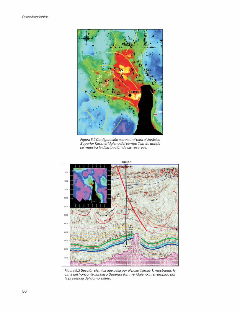
58 PEDESTRIAN AND STREETSCAPE GUIDE
Special ConsiderationsRelated to ChildrenCollision statistics and other information relatedto children are provided in the section of thisguide called About Pedestrians. As pedestrians,children are exposed to more collisions for severalreasons. One of the most problematic characteris-tics of child pedestrians is that their movementsare less predictable than adults. Young childrentend to dart-out into traffic or cross the streetwithout looking for oncoming traffic more oftenthan adults. Young children also lack the visualacuity and peripheral vision to judge speeds ofoncoming traffic and adequacy of gaps in the flowof traffic (Knoblauch, et al). Since children donot drive, they lack the understanding of what adriver’s intentions might be at an intersection orcrossing point. Table 23 lists the special limita-tions of children aged five to nine.
Many pedestrian collisions occur on all types ofstreets, and unfortunately, child pedestrianinjuries occur on local, residential, andneighborhood streets that are straight, paved, anddry. According to the National Safe KidsCampaign, in 1999, almost half of all childpedestrian deaths occurred after school in the lateafternoon and early evening. Most of theseoccurred at non-intersection locations. Drivewaysalso present a danger to young children. Nearlyhalf of all toddler accidents occur when drivers arebacking out of a driveway and do not see youngchildren.
It is important to remember the speciallimitations of this age group when designing forthem. Research has shown that adults uniformlytend to overestimate a child’s capabilities to dealwith traffic, particularly when crossing the street.Adults sometimes fail to realize that manychildren under age nine lack the developmentalskills to safely and consistently cope with movingtraffic.
Improving Student PedestrianSafety—A Cooperative ProcessThe safety of students walking to and from schoolis a major concern of parents, teachers, schools,public works, law enforcement, and the generalcommunity. One of the most important tools forcommunities to develop is a safe walking route
Some Special Limitationsof Children Aged 5 to 9
• Children are shorter than adults; typical eye
height is 3 feet above ground; their field of
vision is different.
• Children have one-third narrower peripheral
vision than adults and are less able to
determine the direction of sounds.
• Children have trouble judging speeds and
distances of moving cars.
• Children are sometimes too small to be
seen by fast moving or inattentive drivers.
• The movements of children are less
predictable than adults.
• Children have shorter attention spans and
may grow impatient at crossings.
• Children have less experience as
pedestrians and may not be fully aware of
dangerous conditions.
Source: A Guidebook for Student Pedestrian Safety; revisedand expanded for this guide.
Table 23
It is important to remember the special limitations ofyoung children when designing for them.
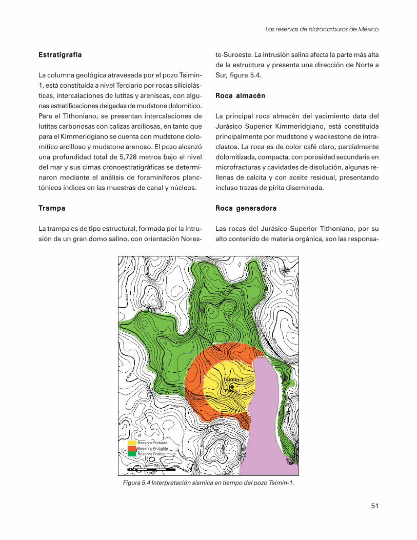
59TOOLKIT 3–CHILDREN AND SCHOOL ZONES
plan for children. It is also important to developa plan to determine which students walk toschools and which ride the school bus. The basicsabout developing school walk routes are describedlater in this toolkit section. The responsibility forstudent pedestrian safety goes beyonddevelopment of “safe walk routes” by schooldistricts. Preparing walk route plans is only partof the overall process (see Table 24).
Identifying problems and implementingimprovements to address these problems in schoolzones and along school walk routes require acooperative effort among public agencies (capitalinvestments and public works funding programs),school districts, private developers, and others inthe community to ensure maximum success.All of these entities must work together andcoordinate with each other to develop pedestrianimprovement programs that provide betteropportunities for children to walk to school.Additional traffic and pedestrian studies may beneeded to identify deficiencies in walking routes.These are identified later in this section.
Georgia school districts should work with publicworks agencies and traffic engineers to mitigatewalk route deficiencies. If hazardous walkingconditions are improved, more students will walkto school, reducing ever-escalating transportation
costs and at the same time making walkways saferfor the community at large.
School Related PedestrianImprovementsThere are two key components of a pedestrianimprovement program that ensure saferconditions for school children:
• A sufficient level of physical facilities providedalong the school walking route and adjacent tothe school (responsibility: local jurisdiction,school district, and private development)
• Effective operation plans and safety programs,consisting of supervisory control elements andstudent/adult education for school trip safety(responsibility: school district, parents, andgeneral community)
This toolkit section focuses on designrecommendations for physical facilitiessurrounding and at the school site and alongschool walk routes. Some information related toschool walk route and safety programs is providedat the end of this section.
On roadways without sidewalks, but with adequateshoulders, children should be encouraged to walk onthe left shoulder, facing oncoming traffic.
Process for Improving StudentPedestrian Safety
• Prepare school walk route plans
• Provide school walk route maps and
information to parents and students
• Identify pedestrian safety deficiencies
• Implement remedial actions and
improvements to address pedestrian safety
concerns
Table 24
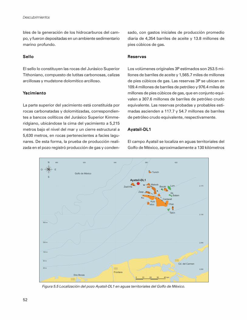
60 PEDESTRIAN AND STREETSCAPE GUIDE
The School as a CommunityFocal PointA broader consideration related to the design ofpedestrian access to schools is how the school isoriented within the community and connected tosurrounding neighborhoods. Schools are often afocal point of the community, serving as muchmore than a place of education by providingoutdoor fields and facilities for play, recreation,meeting, voting, and other community services.Siting a school so it can be easily reached from alldirections and providing a sufficient level ofpedestrian facilities in the vicinity of the schoolfurther help to establish it as a strong componentof the community.
School sites should be centered in the communityand accessible to pedestrians from all sides.Schools can function both as neighborhood parksand school playgrounds. Streets leading to theschool site should be designed to include fullsidewalk or walkway improvements and otherelements that contribute to pedestrian safety andcomfort (traffic calming to slow traffic, goodlighting, clear visibility, and trees for shelter andshade). Intersections and crossings within thevicinity of the school need to be well designed,with a focus on the needs of student pedestrians.Schools should be located where major streetcrossings are minimized. When possible, olderschools should be refurbished instead of buildingnew ones. Older schools are typically located inestablished residential neighborhoods and canserve as an important community focal point.Table 25 lists important elements of a school as afocal point within the community.
Pedestrian-Friendly Schoolsand School ZonesSchool sites and surrounding areas should bedesigned to invite pedestrian travel while alsoimproving pedestrian safety.
School Site DesignDesign and retrofit of schools and school groundsrequires consideration of many factors, toonumerous to list in this guide, but some of thebasic principles of good school site design relatedto pedestrian travel are provided below. Specificsites may have unique conditions that requirespecial design treatments. Good design solutionsare typically based on the adopted standards andpractices of the local jurisdiction, but designsolutions can also exceed established standards
The School as aCommunity Focal Point
• The school site is centrally located in the
community; most children live within
1 mile.
• Pedestrian and bicycle access is available
from all directions.
• Sidewalks, bike lanes, and trails on adjacent
streets or through neighborhoods connect
to the school property.
• Linkages between surrounding
neighborhoods, such as access between cul-
de-sacs, provide enhanced pedestrian
connections to the school.
• Effective traffic control devices are provided
within the surrounding vicinity.
• A school walk route and safety program
exists and safety patrols are provided within
the vicinity.
• School facilities, including the playground,
fields, and meeting rooms, are available for
community use.
• Because of the level of pedestrian
improvements in the area and the design of
the school site, children and adults feel
comfortable walking to the school rather
than riding the school bus or driving cars.
Table 25

61TOOLKIT 3–CHILDREN AND SCHOOL ZONES
Elements of Good School Site Design
• Surrounding streets are equipped with sidewalks
and bike lanes.
• The building is accessible to pedestrians from all
sides (or at least, from all sides with entries/exits).
• Trails and pathways provide direct links between
the school site and the surrounding
neighborhoods.
• Bus drop-off zones are separated from auto drop-
off zones to minimize confusion and conflicts.
• Buses, cars, bicycles and pedestrians are separated
and provided with their own designated areas for
traveling.
• Pedestrian travel zones (sidewalks, etc.) are clearly
delineated from other modes of traffic (through
the use of striping, colored and/or textured
pavement, signing and other methods).
• Parking is minimized; people are encouraged to
walk to school.
• Pedestrians are clearly directed to crossing points
and pedestrian access ways by directional signing,
fencing, bollards or other elements.
• Strategically located, well-delineated crossing
opportunities are provided, including marked
crosswalks at controlled intersections and mid-
block crossings (signalized if warranted).
• Traffic calming devices (raised crossings, refuge
islands, bulb-outs at crossings, on-street parking,
traffic circles, landscaping, etc.) are installed in the
vicinity to slow vehicles.
• View obstructions are avoided so there is clear
visibility of pedestrians throughout the area.
• Parking restrictions are required in areas close to
children walk routes.
• Bus unloading zones should be separated from
vehicular traffic.
• Student crossings and bus loading zones should
provide adequate light, if needed.
Table 26
where desired or necessary to provide a moreeffective pedestrian system.
Table 26 lists a few of the typical elements on andadjacent to school sites that function well forpedestrians and encourage pedestrian travel.
Figure 35 illustrates a typical school site designthat includes many of these features.
Pedestrian Access Routes to the SchoolSidewalks and walkways that clearly define theroutes of access to and from schools should beprovided in all areas surrounding the school andon the school site. Vertical separation (withcurbs) and horizontal separation (planting buffers,ditches, or swales) from motor vehicle traffic arestrongly encouraged to improve the safety ofpedestrians walking along streets. Typicalroadside improvements that may be suitable for
pedestrian travel under varying circumstances arelisted in Table 27. Sidewalks are the preferredfacility school walk routes (see Figure 36).
On roads without sidewalks (often the case inrural areas surrounding schools), widenedroadway shoulders accommodate pedestrians.Shoulders may be paved or unpaved, but ifunpaved, a well compacted and grassed stablesurface is highly recommended. At a minimum,A Guidebook for Student Pedestrian Safetyrecommends that shoulders that are part of adesignated school walk route be minimum 5 feetwide (8 feet preferred) and be provided on bothsides. If a shoulder can only be provided on oneside, provide a minimum of 8 feet in width toallow students to walk off the roadway in eitherdirection. Although this is not the most desirablesolution (shoulder on only one side), it is betterthan a scenario where there are no pedestrian

62 PEDESTRIAN AND STREETSCAPE GUIDE
Table 27
Roadside Pedestrian Improvements Along School Walk Routes
• Well compacted and grassed stable surface is
recommended for shoulders
• Paved shoulder (recommended as an interim
solution only; if an accessible route of travel,
edge treatment is necessary)
• Paved walkway or sidewalk separated from
roadway by ditches, swales, or planting buffer
(good long-term solution; often used in rural
and residential areas; 5-ft. minimum separation
required by AASHTO)
• Adjacent sidewalk with curb and gutter or
vertical curb (good long-term solution; often
used in urban areas)
Source: A Guidebook for Student Pedestrian Safety; revised andexpanded for this Guide
School Site Design
Figure 35

63TOOLKIT 3–CHILDREN AND SCHOOL ZONES
minimum of 48” contiguous space remains aftermilling the rumbles. (Note that under operations,debris will accumulate starting approximately 12”from the edge of the traveled way, and increasingfarther from the traveled way. Regular sweepingmat be required by the local jurisdiction to keepsuch a shoulder usable, particularly by bicycles.)Check with your local agency for specificstandards that may be applicable to your project.For more information related to the design ofsidewalks, walkways, and shoulders, refer toToolkit Section 5.
Along roads with adequate shoulders, childrenshould be generally directed to walk on the leftshoulder facing oncoming traffic. However,children may walk on the shoulder on the sidewith the flow of traffic for a short distance to orfrom school if such action reduces the number ofroad crossings they must make.
School Bus Stop DesignBus stops need to be adequately designed toprovide sufficient waiting area away from theroadway for the number children using the stop.In urban areas, bus stops are often designed andconstructed as part of private developmentprojects. In rural areas, bus stop locations oftenconsist of a widened shoulder area adjacent to theroadway. Figures 38 and 39 illustrate two typicaldesigns for school bus stops - one for areas where
Students need to be able to travel safely to and from thebus stop.
Figure 37
Widened Shoulder(in Rural Areas or as Interim Solution)
Sidewalk
Figure 36
travel areas at the roadside. This guiderecommends that shoulder use for pedestriantravel be considered as only an interim solutionuntil separated walkways or sidewalks can bedeveloped along roadways leading to the school.Refer to Figure 37.
Design standards for shoulders vary amongjurisdictions. Consider using contrastingmaterials, e.g. asphalt roadway with concrete orcrushed rock shoulders, for better visibility. Inrural areas, rumble strips should be milledbetween the traveled way and the outside edge ofthe shoulder as long as an FHWA-recommended

64 PEDESTRIAN AND STREETSCAPE GUIDE
sidewalk either exists or can be constructed, andone for areas where widened shoulders function asthe pedestrian travel zone. Check with your localagency and school district for specific designpractices that may be applicable in your area.
Visibility at Crossings and AlongSchool Walk RoutesChildren are smaller than adults and moredifficult for motorists to see at crossings. Tofunction safely, crossings should provide anunobstructed visual field between motorists and
Typical Bus Stop Design for Urban Location
Figure 38
Typical Bus Stop Design for Rural Location
Figure 39
For tree planting and landscape requirements within state highway rights-of-way, refer to GDOT standards (MOG 6160)

65TOOLKIT 3–CHILDREN AND SCHOOL ZONES
pedestrians. Certain obstructions such as streetlights, mailboxes, and telephone booths shouldnot hide the pedestrian from view. Landscapingcan enhance the pedestrian environment and treescan provide shade and shelter from wind andweather. However, care must be taken to selectlower growing shrubs that won’t block views ofpedestrian. A maximum shrub height of 2 feet issuggested for school zones. Trees along streetsshould be upward branching, with lower brancheslocated at least 6 feet above ground.
Parked vehicles (even momentarily) are also visualobstructions, especially for children, wheelchairusers, and people of small stature. Forrecommended setbacks for parked vehicles nearpedestrian crossing points, refer to Toolkit 6 -Intersections.
Traffic Control and CrossingsNear SchoolsSpecial considerations related to various types ofcrossings and traffic control methods used nearschools are described in the next part of thissection of the guide. More specific designinformation related to traffic control and crossingtreatments can be found in Toolkits 6, 7, and 8.
General ConsiderationsTraffic control related to schools is a sensitive andcontroversial subject. The methods used toprotect children as they walk to school need to becarefully considered and analyzed by trafficengineering professionals on a case-by-case basisbefore solutions are implemented.
According to the Institute of TransportationEngineers (ITE) manual, Design and Safety ofPedestrian Facilities, the majority of drivers do nottypically reduce their speeds in school zonesunless they perceive a potential risk, such as thepresence of police or crossing guards, or clearlyvisible children. Overuse of signs and otherdevices can cause drivers to be less responsive andattentive. Unnecessary installation of traffic
controls lessens the respect for warranted trafficcontrols. Placement of signs, crossing treatments,and traffic control devices need carefulconsideration.
According to the ITE’s School Trip Safety ProgramGuidelines, a number of elements should bestudied to determine the appropriate types ofcrossing treatments and traffic control in schoolzones or along school walk routes, including, butnot limited to:
• existing and potential traffic volumes andspeeds,
• inventory of existing traffic control devices androadway facilities,
• adequacy of gaps in the stream of traffic,
• numbers and ages of children crossing(pedestrian volumes and characteristics),
• adequacy of sight distance,
• collision statistics, and
• location of the school and relationship tosurrounding land uses (both existing andplanned).
These elements should be considered under thedirection of a professional traffic engineer and theresults reviewed with the local public worksagency, as well as a safety advisory committeeestablished by the school district. There aremany variables related to these elements and howthey might influence design treatments.
Types of Traffic Control and CrossingTreatmentsThere are several types of crossing treatments andtraffic control devices that may be appropriate inschool zones and along school walk routes undervarying conditions. Crossing treatments areusually necessary at locations where adequate gapsare not currently available in vehicular flow toallow school children to cross safely. Table 28lists potential types of traffic control and crossingtreatments that may be implemented near

66 PEDESTRIAN AND STREETSCAPE GUIDE
schools. Each of these treatments is summarizedbelow. More detailed design information formost of these can be found in other sections ofthis guide. Check with your local agency todetermine the accepted practices for your specificproject.
Reduced Speed ZonesThe school zone speed limit is typically aminimum of 10 m.p.h. less than the immediatelyadjacent posted speed limit, and a maximum of20 m.p.h. less than the immediately adjacentposted speed limit. This speed limit is usuallyrequired to extend 300 feet in either directionfrom the school and from marked crosswalks nearthe school. A lower maximum speed limit may beestablished within a school zone or other areawhenever the local jurisdiction determines that onthe basis of an engineering and trafficinvestigation, the maximum speed permitted ismore than is reasonable and safe under existingconditions. Consider reducing the speed limit inschool zones where special hazards exist and a
traffic engineering study determines that such aspeed reduction is warranted. Georgia law saysspeed limits in school zones can not be reduced bymore than 20 m.p.h. and can not be less than 25m.p.h. on state routes.
Traffic CalmingTraffic calming techniques are used to slow vehiclesand to reduce non-local through-traffic. Varioustechniques can be used on all classifications ofroadways, but traffic calming is generally veryeffective on local access streets in residential areas.
On street systems surrounding schools and inschool zones, traffic calming can be an effectivemeans to create a safer and more comfortableenvironment for children walking to school. Someexamples of traffic calming techniques that may beappropriate include raised crossings, refuge islandsat crossings, traffic circles, chicanes, bulb-outs,narrower streets, on-street parking, trees andlandscaping along the right-of-way, and gateways.Speed enforcement and speed watch programs arealso good methods for calming neighborhood trafficin school zones, although their effectiveness mayonly last for a limited time, unless consistentlyimplemented. Refer to Toolkit Section 8 for morespecific design recommendations related to trafficcalming.
Marked CrosswalksThe issue of providing marked versus unmarkedcrosswalks at intersections is often debated. For adiscussion on studies related to the effectiveness ofmarked and unmarked crosswalks, refer to ToolkitSection 6 — Intersections.
All crossing points within school zones and alongschool walk routes, typically within 1 mile of aschool site (but may include intersections andcrossings outside of this distance), should beevaluated to determine where to mark crosswalks.The Manual on Uniform Traffic Control Devices(MUTCD), requires crosswalks to be marked at allintersections on established routes to schools:
Potential Traffic Control andCrossing Treatments
Near Schools• Reduced speed zones
(see discussion below)
• Traffic calming techniques
• Marked crosswalks at intersections
and mid-block
• Stop controlled crosswalks
• Signalized crossings
(with pedestrian actuators)
• Flashing beacons
(check with your local agency)
• Grade separated crossings
• Crossing guard or school patrolled crossings
• Signing and marking
Table 28
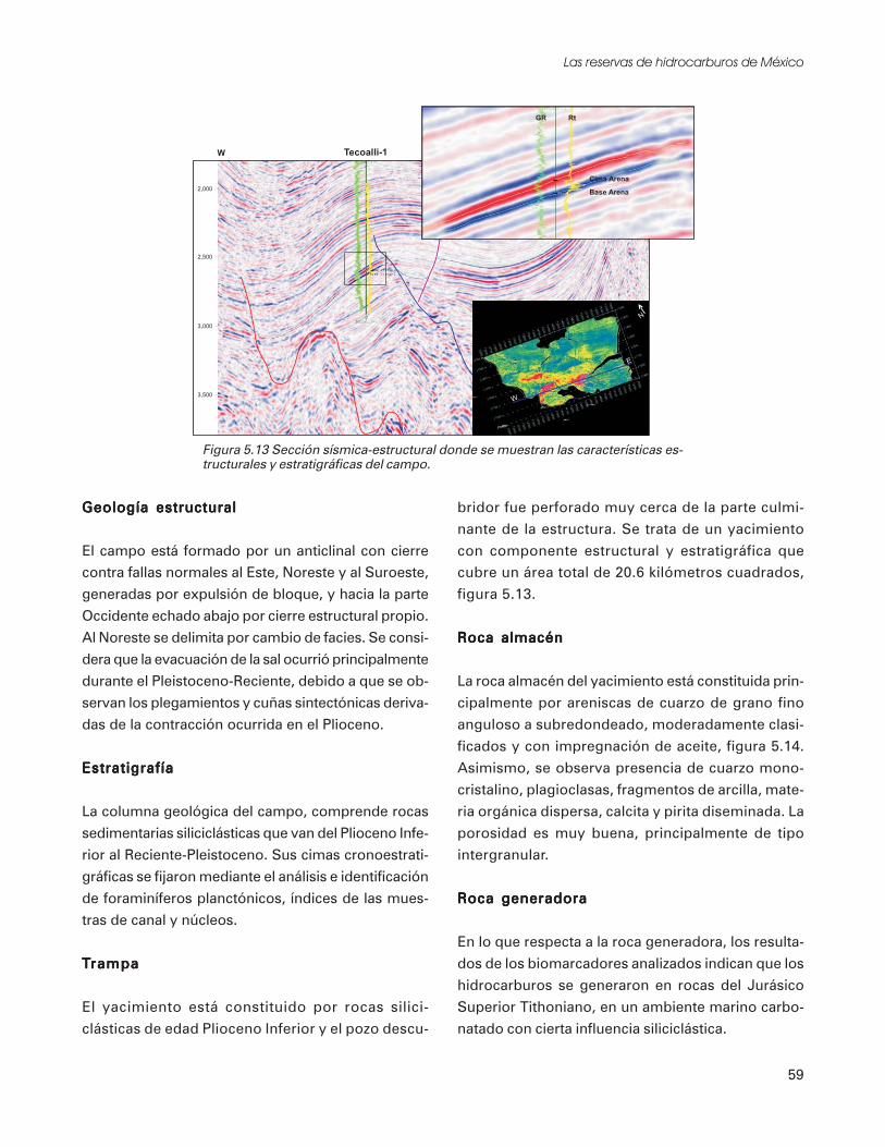
67TOOLKIT 3–CHILDREN AND SCHOOL ZONES
• where there is measurable conflict betweenvehicles and kindergarten or elementarystudents (while crossing),
• where students are permitted to cross betweenintersections, or
• where students could not otherwise recognizethe proper place to cross.
Marked crosswalks are often located at signalizedand stop controlled intersections or mid-blockcrossings. They may also be located atintersections or locations where traffic volumeswarrant the need for pedestrian signals using theMUTCD guidelines, but none are provided.Marked crosswalks may be provided at otherlocations when a traffic engineering analysisdetermines the need.
School patrolled crossings (with either studentpatrollers or adult crossing guards) should not beoperated unless proper traffic control devices arein place. At a minimum, these devices shallconsist of school crossing warning signs (S1-1),marked crosswalks, and school speed limit signs(R2-1). GDOT discourages mid-block crossingson state routes. For design considerations relatedto the various types of crosswalk markings, refer toToolkit Section 6 - Intersections.
Stop Controlled CrosswalksStop controlled crosswalks, consisting of stopsigns and stop bars, with or without actualcrosswalk markings, provide the added protectionof having all vehicles stop at the crossing. Sincevehicles must stop at the stop signs in theselocations, there is typically less need for paidadult crossing guards or student patrols.Additional protection with crossing guards and/orstudent patrols may be necessary at intersectionswhere pedestrian volumes are high and trafficvolumes are moderate or higher.
Signalized Crossings (With Pedestrian Actuators)New traffic signals should provide markedpedestrian actuation buttons and symbolic “walk/don’t walk” indicators. It is appropriate to installsignals at locations other than signalizedintersections for pedestrian crossings. Examplesinclude frequently used mid-block crossings andcrossings to school sites.
The MUTCD defines warrants for installation oftraffic signals at school crossings. The MUTCDrecommends that a traffic engineering study beconducted to determine the frequency of gaps in thevehicular traffic stream that allow pedestrians tocross. When crossing gaps are less than one perminute and of insufficient duration to allow a givensize of group to cross, a signalized crossing may beneeded.
Provide pedestrian signal indications and pushbuttons at signalized school crossings and markthe designated crosswalks. For a completediscussion on signal placement and design, referto the MUTCD.
The services of a school patrol program (adultcrossing guard or student patroller) may not benecessary at all signalized intersections near theschool unless special problems exist. Schoolpatrol services can provide additional protection atintersections where pedestrian volumes are highand traffic volumes are moderate to high. See thediscussion under School Patrolled Crossings forA school patrolled marked crosswalk
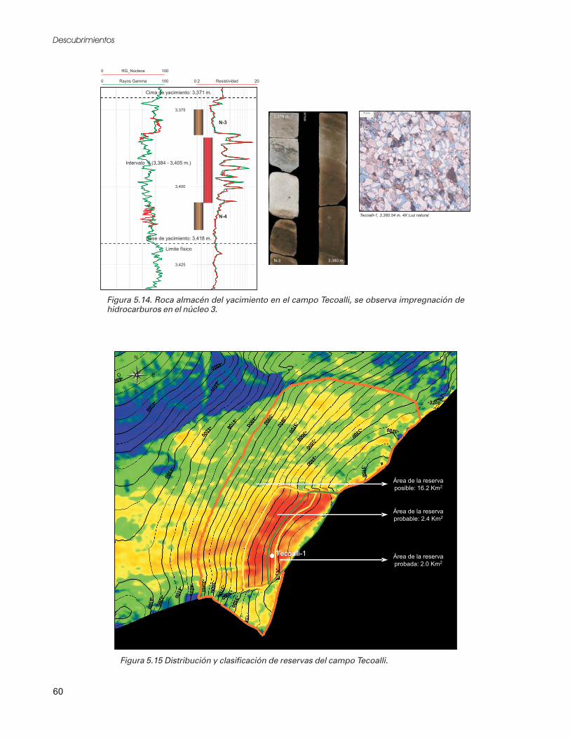
68 PEDESTRIAN AND STREETSCAPE GUIDE
appropriate locations for adult crossing guardsversus student safety patrollers.
More information related to intersections,crossings and signalization can be found inToolkits 6 and 7.
Flashing BeaconsFlashing beacons are common devices used inschool zones, and they come in varying styles(mounted to school speed limit signs, andoverhead crosswalk signs). The effectiveness offlashing beacons is an often debated issue. Theflashing light alerts drivers in advance to thepotential of pedestrians without forcing them tostop. Some studies indicate that after drivershave become accustomed to seeing the beacons inadvance of conditions that do not appear to betruly unusual, they stop paying attention to theflashing light. This can result in a disregard forall beacons, even those that are truly needed(Flashing Beacons, Association of WashingtonCities and County Road Administration Board).
Flashing beacons are most effective when used as awarning of truly unusual or hazardous conditionsnot readily visible to the driver, such as a stopsign located just beyond a curve that is hiddenfrom view of the driver. It is a common practicefor flashing beacons to be attached to school speedlimit signs. These beacons are only activatedduring hours that students are present in theschool zone. Flashing beacons are discussed under
section 4E of the MUTCD relating to hazardidentification beacons, and a mid-block crosswalkis one of the specific applications noted for thisdevice. Please refer to the MUTCD for morespecific guidance related to the use of flashingbeacons.
Grade Separated CrossingsGrade separated crossings may be necessary tophysically separate the crossing of a very heavyvolume of school pedestrian traffic and a heavyvehicular flow, or where the roadway’s crosssection is exceptionally wide, such as freeways andprincipal arterials. Typical types of gradeseparated crossings include overpasses andunderpasses. Because these facilities are costly incomparison to other crossing solutions, theyshould be considered only in areas where largenumbers of pedestrians will benefit. Gradeseparated crossings need to be easily accessibleand convenient to use or they may lose theireffectiveness. Pedestrians may be tempted to trycrossing at grade instead of using the overpass orunderpass. For additional design guidelinesrelated to grade separated crossings, refer toToolkit Section 7 - Crossings.
Crossing Guard and Student PatrolControlled CrosswalksSome specific design considerations related toschool patrolled crosswalks (adult crossing guardor student patrolled) have already been discussedunder the various traffic control and crossingtreatments in this section. Traffic engineeringstudies can determine the need for and placement
Adult crossing guard at busy intersection near anelementary school.
Flashing Beacon

69TOOLKIT 3–CHILDREN AND SCHOOL ZONES
of school patrols at crosswalks on a case by casebasis. It is important to coordinate with localjurisdictions on the use of school patrollers.
The use of well trained adult crossing guards isconsidered to be one of the most effectivemethods of school zone traffic control. Studentsafety patrollers, who are most often students atthe school, can also provide supervision anddirection at crosswalks near schools. Adultcrossing guards can be appointed as members ofthe school patrol under certain conditions (seeTable 29).
Crossing guards should be hired employees,trained to work with children. Untrained orvolunteer crossing guards may not be adequatelyprepared to assist children in emergencysituations. Training for crossing guards includes
making sure guards are in the proper location formaximum supervision of children and makingsure guards interact with children to teach themthe right techniques for crossing streets. Crossingguards should wear an easily identified uniformand carry identification and phone numbers forauthority in case of emergencies.
Sometimes vehicular traffic is such that control bya police officer, adult school patrol member or atraffic signal is required. In this case, studentschool patrol members can assist by directingstudents to cross in conformance with thedirection given by the police officer or adultpatrol member, or in conformance with the timecycle of the signal. Student safety patrol membersshould typically be selected from upper gradelevels, preferably not below the fifth grade.Student safety patrollers should not be directed orauthorized to halt or direct vehicular traffic.
Their purpose is to supervise and assist children,not to control vehicular traffic. Table 30describes the primary functions of student safetypatrollers.
Signing and MarkingFigure 40 shows typical signing for school areatraffic control. Descriptions of the types of schoolsigns authorized by the MUTCD and used byGDOT are discussed below and shown in Figure41.
When to UtilizeAdult Crossing Guards
• Lack of adequate gaps due to high volume
of traffic
• When 85 percent of the traffic exceeds the
speed limit by 5 mph
• When there is restricted sight distance
• When the location or distance from the
school building is such that poor supervision
of students would otherwise result
• When there is a high volume of traffic in a
crosswalk
• When the location has been determined by
either school or law enforcement authorities
to be beyond the capacity of a student to
make rational decisions concerning safety
• When there is an excessive volume of
pedestrian traffic over a highway
• When any of the above criteria exists and
there is a lack of an alternative school route
plan
Table 29
Primary Functions ofStudent Safety Patrollers
• Instruct, direct, and control students in
crossing streets at or near schools
• Assist teachers and parents in instructing
school children in safe pedestrian practices
Source: A Guidebook for Student Pedestrian Safety
Table 30

70 PEDESTRIAN AND STREETSCAPE GUIDE
Typical Signing for School Area Traffic
Source: Manual on Uniform Traffic Control Devices
Figure 40
*
* On state routes only

71TOOLKIT 3–CHILDREN AND SCHOOL ZONES
School Advance Sign (S1-1)The School Advance sign is intended for use inadvance of locations where school buildings orgrounds are adjacent to the roadway. This signcan be supplemented with a diagonal downwardpointing arrow (W16-7) to show the location ofthe crossing. The School Advance sign is placednot less than 150 feet in advance and not morethan 700 feet in advance of the school grounds orschool crossing.
School Bus Stop Ahead (S3-1)School Bus Stop Ahead signs are intended for usein advance of locations where a school bus stop isnot visible from 500 feet in advance. It is notintended for these signs to be placed everywhere aschool bus stops, but only in locations whereterrain or other features limit sight distance andthere is no opportunity to relocate the stop to amore visible location.
School Speed Limit Signs (R2-1, S4-2, S4-1, S5-1)
School Speed Limit signs are used to indicate thespeed limit within the school zone. School SpeedLimit signs may be accompanied by signs thatindicate applicable hours or conditions of speedlimit reduction (“when children present”). Aflashing beacon along with a sign “when flashing”may also be used to identify the periods when theschool speed limit is in force. In Georgia, anadvanced warning sign must be placed 700 feet inadvance of the point at which the speed reductionis required, if the speed limit reduces by 20 mph(Code Section 40-6-183).
Overhead Crossing SignsOverhead School Crossing signs are sometimesused at school crossings, but are not containedwithin the MUTCD and are considered to beextraordinary traffic control devices. Thesedevices are only installed at locations where schoolauthorities request supplemental traffic control formarked school crosswalks and only after a trafficengineering analysis considers other traffic controlmeasures. When such signs are installed, theyshould include flashing lights that are on only atthe time school children use the crosswalk. Theschool district should be responsible for ensuringthat the flashing lights are on at the appropriatetimes. Flashing lights may be similarly used onSchool Speed Limit signs if installed in accordancewith the MUTCD requirements.
School Zone ColorsGDOT has restricted the use of fluorescentyellow-green signage. This color of sign is to beused only in school zones, and whensupplementing W11-1 and W11-2 signs (bicycleand pedestrian presence) with the AHEADplacard (W16-9p). It heightens driver awarenessby placing an unexpected element (sign color) intheir environment. Drivers who see the differentcolored signs then come to know that thedifferent color represents a school zone,prompting them to look carefully for children asthey are driving through. The mixing of standardyellow and fluorescent yellow-green backgroundswithin one zone or area should be avoided.
Figure 41
Source: Manual on Uniform Traffic Control Devices
S4-4 S4-1
S5-1 R2-1 and S4-2
S1-1
School Signs

72 PEDESTRIAN AND STREETSCAPE GUIDE
“School” MarkingsThe MUTCD allows word and symbol markingson the pavement for the purpose of guiding,warning, or regulating traffic. They are typicallylimited to not more than a total of three lines ofwords or symbols and are white in color. Thesetypes of markings are not used for mandatorymessages except in support of standard signs.Figure 42 illustrates the school pavement markingdesign standard.
Other types of street crossing marking devices arediscussed in Toolkit sections 6 and 7.
School Walk Routes andSafety ProgramsSchool walk route plans are required by somestates and local jurisdictions. It is recommendedthat the state, local jurisdictions, or schooldistricts develop a plan for safe walk routes toschool. Procedures for developing school walkroutes are listed in Table 31. School walk routeplans can be an important tool for communities.It can give parents and teachers assurance thatthese routes will be made safe for children’s travel.
Once the school walk route has been established,pedestrian safety deficiencies along the walk routeneed to be identified, then remedial actions canbe considered and implemented as fundingbecomes available.
Educational Tools andPrograms for Child SafetyMany tools currently exist that can help parents,teachers, and school officials assist in providingsafe travel for children. These tools demonstratethat child pedestrian travel is a national issue.Below are some of the tools available.
• Kids Walk-to-School, A Guide to PromoteWalking to School – a document to promotewalking to school produced by the Center forDisease Control and Prevention
• Walk to School Day – an event devoted toencouraging walking to school and recognizingthe need to create safe walking communities forchildren, initiated by the Partnership for aWalkable America. www.walktoschool-usa.org/
• National Kids Safety Campaign – a resourceavailable to the community to help preventchild injuries, including pedestrian collisions.
One Lane School Marking
Source: Manual on Uniform Traffic Control Devices
Figure 42
Procedures for DevelopingSchool Walk Routes
1. Form Safety Advisory Committee (SAC)
2. Prepare base maps
3. Inventory existing walking conditions
4. Inventory traffic characteristics
5. Design the walk routes
6. Prepare the draft walk route maps
7. Review the route maps with the SAC
8. Have route maps approved by the
school board
9. Distribute and explain the maps
10. Evaluate the program
Source: A Guidebook for Student Pedestrian Safety
Table 31

73TOOLKIT 3–CHILDREN AND SCHOOL ZONES
Brochures such as “Safe Kids are No Accident”are available to teach children how to becomeresponsible pedestrians. www.safekids.org
• Way to Go School Program – a Canadianprogram committed to providing resources toschool communities to develop traffic safetyawareness programs and to increase theopportunities for children to walk, bike, orrideshare to school. www.waytogo.icbc.bc.ca
Ongoing MaintenanceThe school district and school site officials areresponsible for providing ongoing maintenance ofpedestrian facilities and traffic control elements onthe school site. This includes sidewalks withinthe right-of-way adjacent to the school site.Public and private property owners are typicallyresponsible for repairs and reconstruction of thesidewalk within the street right-of-way adjacent totheir property. Local jurisdictions are responsiblefor maintaining facilities and traffic controlelements at intersections and mid-block crossings.On an annual basis, before the opening of schooleach year, elements that affect pedestrian travel inthe area of the school should be inspected. Someof the things to look for include:
• Signs that are clearly visible and easy to read(paint has not worn off; tree branches are not inthe way)
• Traffic control devices, signals, and actuatorsthat function properly
• Sidewalks and walkways that are clear ofobstruction; bikeable and walkable shouldersthat are reasonably free of debris; pavement thatis smooth
• Crosswalks and pavement markings that areclearly visible
• Pedestrian visibility that is not compromised byovergrown landscaping, parking, signs, fencing,or other obstacles at intersections, crossings, andalong walkways
Other Sources of InformationFor more specific design guidelines for variouspedestrian facilities that may be developed withinthe vicinity of schools, refer to the other toolkitsections of this guide, including Toolkit 2 -Accessibility, Toolkit 4 - Trails and Pathways,Toolkit 5 - Sidewalks and Walkways, Toolkit 6 -Intersections, Toolkit 7 - Crossings, and Toolkit8 - Traffic Calming.
The following sources are recommended fordesign recommendations and other informationrelated to pedestrian facilities for children andschool zones. Please see the Resource Guideincluded at the end of this guide for completebibliography information.
A Guidebook for Student Pedestrian Safety, FinalReport, KJS Associates Inc., MacLeod Reckord,and Educational Management Consultants
Childhood Injury Prevention, A Directory of Resourcesand Program in Washington State, WashingtonState Department of Health
Design and Safety of Pedestrian Facilities, A ProposedRecommended Practice of the Institute ofTransportation Engineers, ITE Technical CouncilCommittee 5A-5
Elementary School Catalog, AAA Foundation forTraffic Safety
Florida Pedestrian Planning and Design Guidelines,University of North Carolina
Guidelines for the Installation of CrosswalkMarkings, Steven A. Smith and Richard L.Knoblauch
Handbook for Walkable Communities, WashingtonState Pedestrian Facilities Planning and DesignCourses, Dan Burden and Michael Wallwork, PE
“Make Their First Steps Safe Ones,” Robert B.Overend
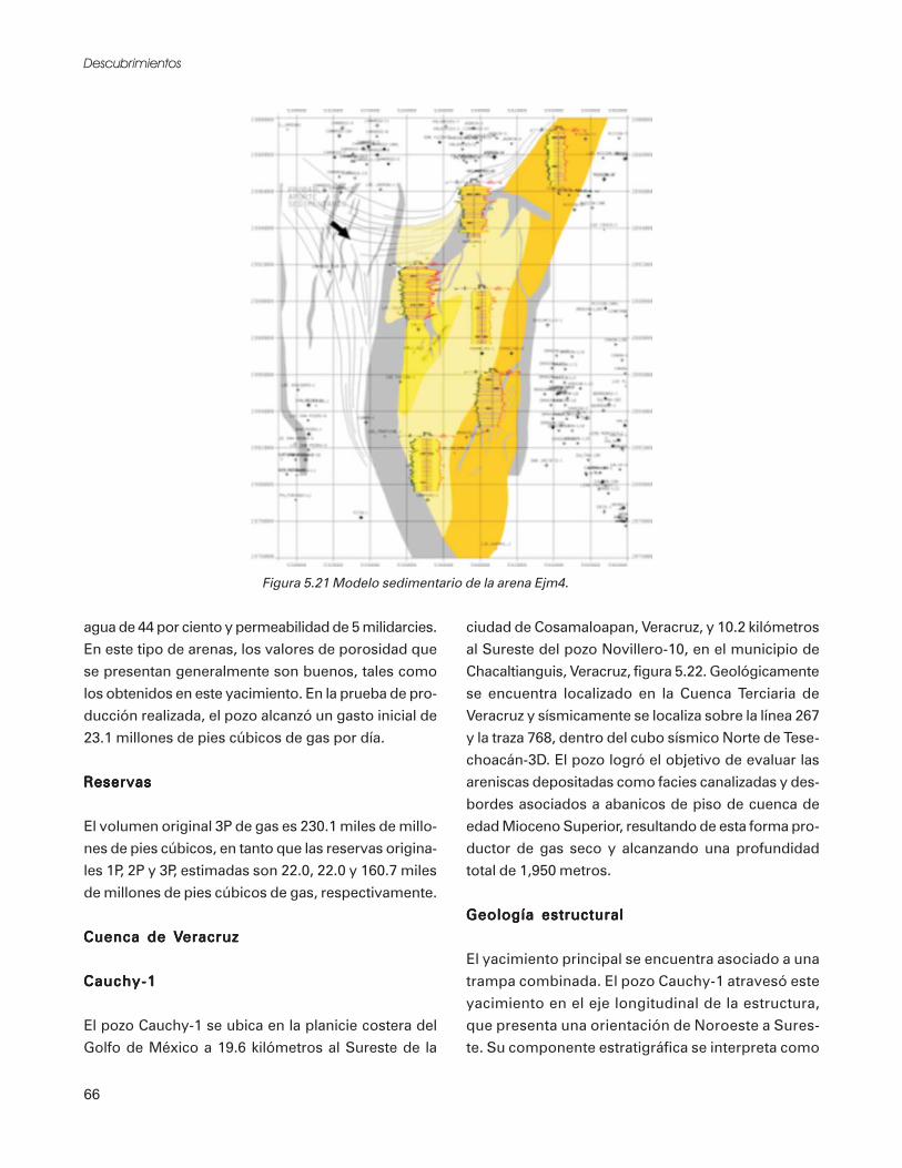
TOOLKIT
TRAILSAND PATHS
75
4
This Toolkit SectionAddresses:• Trails and Paths Across Multiple Jurisdictions
• Regional Connectivity
• Accessibility of Trails and Paths
• Special Considerations for Shared Use Paths
• Recommended Dimensions
• Paving and Surfacing
• Grades, Cross Slopes, and Drainage
• Shoulders, Side Slopes, and Railings
• Connections and Crossings
• Managing Motor Vehicle Access
• Vegetation and Landscaping
• Seasonal and Nighttime Use
• Maintenance
• Other Sources of Information
This section provides design recommendationsrelated to various types of trails and paths that areindependently aligned and not typically locatedparallel to streets or within road rights-of-way.These types of facilities are generally found withinareas such as open spaces of planned residentialcommunities and subdivisions, abandonedrailroad rights-of-way, utility easements, parksand greenways, campuses, private developments,along waterfronts, and in other settings.
Trails and paths commonly serve a variety ofpedestrians, including commuters, school-children, neighborhood residents, and recreationalusers such as joggers and skaters. Some trails aredesigned to also serve bicyclists. Trails that aredesigned primarily for a recreation experience andfor walking speeds are called “recreation trails.”Paths that are designed for transportationpurposes and can comfortably accommodatebicycle speeds are called “shared use paths.”
Trails and Paths AcrossMultiple JurisdictionsWhen a trail or path crosses over boundaries ofmultiple jurisdictions (state, county, and cityrights-of-way, parks, and railroads), cooperativecoordination between jurisdictions for theplanning, design, operation, and maintenance ofthe facility is essential. Communities can benefitfrom working together to coordinateimprovements and linkages for region-widenonmotorized systems.
Regional ConnectivityTrails and paths can enhance pedestrian mobilityand regional connectivity. When well planned,
Trails and paths provide recreational opportunities aswell as increased transportation choices.
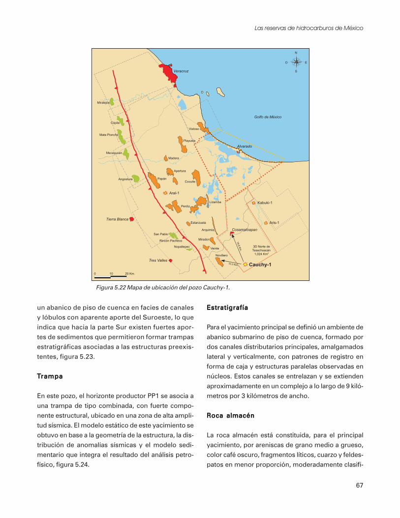
76 PEDESTRIAN AND STREETSCAPE GUIDE
designed, and maintained, trails can provideconvenient routes of travel within communities,linking popular origins and destinations such asparks, schools, and community centers. Trails arenot typically an adequate substitute for a fullsystem of on-street nonmotorized improvements.Rather, they serve as important linkages in theoverall nonmotorized system.
Accessibility of Trailsand PathsTrails and paths provide important outdoorrecreational opportunities and transportationalternatives for everyone. It is always the bestdesign practice to provide pedestrian facilities thatare accessible, including trails. At least one travelroute, located entirely within the site boundary,must connect public transportation stops,accessible parking spaces, passenger drop-off andloading areas, and public streets or sidewalks withthe accessible entrance to the site and primarydeveloped activities and elements (buildings,shelters, restrooms, and programs). To themaximum extent feasible, the accessible routemust coincide with the route for the generalpublic.
If the recreational trail or path is not functioningas an accessible route of travel between buildingsand facilities and cannot be designed to be fullyaccessible due to topography or other physical site
constraints, it may be exempt from some of thedesign requirements related to the Americans withDisabilities Act (ADA). Check with your localagency, GDOT, and federal agencies such as theUS Architectural and Transportation BarriersCompliance Board (Access Board) and FHWA todetermine if your project is eligible for certainexemptions from the ADA design provisions.
Even though full compliance with the ADAdesign provisions may not be required, trailsshould be designed to provide accessiblerecreation experiences for everyone to themaximum extent possible. An accessible spurtrail that extends off the main trail to a specialpoint of interest, or sections of trail that servevarying levels of ability are examples of accessiblerecreation experiences that can be provided whenit is not feasible to develop the entire trail as anaccessible route. Figure 43 illustrates anaccessible trail.
For more accessibility design guidelines andinformation related to the ADA, refer to Toolkit2 - Accessibility.
Multiple Levels of AccessibilityRecreation trails (and in some cases shared usepaths) are commonly designed to provideexperiences for differing levels of accessibility.The levels of accessibility served may depend onthe setting. In urban parks and open spaces, a
Accessible Trail/Path
Figure 43
Silver Comet Trail is a regional trail spanning 57miles in Polk, Palding, and Cobb counties.

77TOOLKIT 4–TRAIL S AND PATHS
full range of accessible recreation opportunities,including trails that provide easy access, aretypically expected by the general public. In ruraland primitive areas, full accessibility is notgenerally expected, and trails that serve varyinglevels of accessibility are commonly provided.Some trails may serve as accessible, while othersmay have steeper gradients and unpaved surfaces.Individuals are then free to choose a trail thatprovides the recreation experience and degree ofchallenge that they desire.
A recent publication of the FHWA, DesigningSidewalks and Trails for Access: Part II, BestPractices Design Guide, provides excellentinformation on trail design to accommodate avariety of users with disabilities. Universal Accessto Outdoor Recreation: A Design Guide, developedby the PLAE and the USDA Forest Service,provides extensive design guidance related tooutdoor recreation trails. It includes a recreationtrail rating system and suggests that trails besigned to indicate the level of accessibility: easy,moderate, and difficult (see Figure 44).
The design guide contains design guidelines fortrails classified as easy, moderate and difficult.There are several other sources of informationavailable for trail design. See the list at the end ofthis Toolkit section for other good sources.
Special Considerations forShared Use PathsThere are a few special considerations for theplanning and design of shared use paths – multi-use trails that are designed primarily for atransportation function serving pedestrians andbicyclists. Design of shared use paths needs tocarefully consider the various skill levels,experience, and characteristics of the differentusers.
Universal Levels ofAccessibility Signs
Source: Universal Access to Outdoor Recreation, A Design Guide
Figure 44
Trails and paths serve a wide variety of users.

78 PEDESTRIAN AND STREETSCAPE GUIDE
Minimizing Conflicts BetweenTrail UsersThe mix of pedestrians and bicycles on a shareduse path is not always a desirable situation due tothe high potential for conflict. Paths heavily usedby commuting bicyclists present problems forfamilies on recreational strolls. Children areparticularly at risk on shared use paths becausethey tend to travel at slower speeds than theaverage bicyclist and their movements areunpredictable. They may change directionunexpectedly in front of an approaching bicyclist.Conflicts between bicyclists and pedestrians canbe avoided by designing the path to separatethem.
When paths must be shared by pedestrians andbicyclists, they need to be designed in accordancewith applicable standards (refer to GDOT andAASHTO design requirements). Adequatevisibility and sight distance is crucial. Designtreatments that help to improve shared use pathsso that they are safer for use by everyone include:
• Horizontal and vertical alignment to ensureclear lines of sight for pedestrians and bicyclists
• Wide shoulders, 2 feet minimum on each side,to provide stopping and resting areas and allowfor passing, and widening at curves
• Avoidance of view obstructions at edges of thetrail by placing signs, poles, utility boxes,garbage cans, benches, and other elements awayfrom the edge of the path and using low-growing landscaping or high-branching trees
• Use of bicycle speed limits
• Use of delineation and separation treatments(see Table 32)
• Use of directional signing
• Signing and marking (refer to the Manual onUniform Traffic Control Devices); a 4-inch widecenterline stripe may be considered for shareduse paths with heavy volumes of pedestrians andbicyclists, on curves with restricted sightdistance, and on paths where nighttime use is
expected (see Figure 45); edge lines can also bebeneficial on paths experiencing nighttime use
If a shared use path must accommodate a highernumber of users, it needs to be as wide as possiblewith a desirable paved width of 12 feet or 10 feetminimum, and 2-foot wide shoulders on bothsides (see Table 34, Recommended Dimensions).Figure 46 illustrates a typical shared use pathshared by pedestrians and bicyclists.
A separate, soft-surface jogging or equestrian pathmay be constructed using wood chips, compactedcrushed gravel, or other suitable material, parallel tobut separated from the paved path (see Figure 47).
Figure 46
Shared Use Path
Figure 45
Multi-Use Shared Use Path Striping
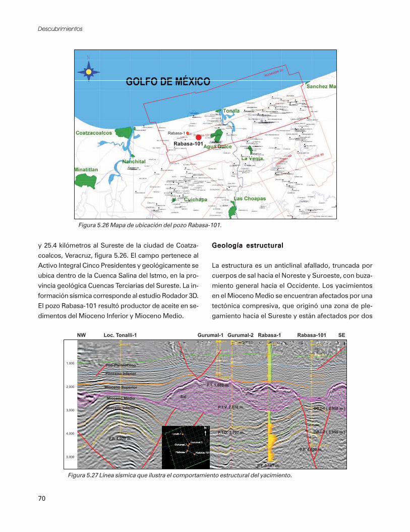
79TOOLKIT 4–TRAIL S AND PATHS
Some special delineation treatments that can beimplemented to help minimize conflicts betweenpedestrians and other trail users are listed inTable 32.
Shared Use Paths Next to RoadwaysShared use two-way paths aligned along a streetoften do not function well due to problemsrelated to bicycle use. For example, on a shareduse two-way path, some of the bicyclists will betravelling against the normal flow of motor vehicletraffic, which is contrary to the rules of the road.
Conflicts at intersections and driveways are amajor concern on paths adjacent to roadways.Motorists will often not notice bicyclists comingtoward them on the right, since they do not expectto see them travelling against the flow of traffic.Additional problems are listed in the AASHTOGuide for the Development of Bicycle Facilities.
Shared use paths placed next to roadways can lead tohazardous conditions.
The feasibility of developing a shared usepedestrian and bicycle path within the right-of-way and adjacent to a roadway should be carefullyconsidered. The following conditions should existbefore determining that a shared use path withinthe right-of-way is necessary:
• The path can be separated from motor vehicletraffic. AASHTO standards require a minimumhorizontal separation of 5 feet or a physicalbarrier, as illustrated in Figure 48.
• Development of bike lanes and sidewalks as analternative to the shared use path would not bea feasible alternative. (Bike lanes and sidewalkstypically take up less space than shared usepaths within the right-of-way and allow bicycliststo travel with the normal flow of traffic.)
• There are no reasonable alternative alignmentsfor bikeways and sidewalks on nearby parallelroutes.
Delineation/Separation Treatmentsfor Shared Use Paths
• Colored paving
• Signing
• Textured paving or paving patterns*
• Pavement markings — symbols or words
(slip resistant finish)
• Striping with education program about trail
use and other measures**
• Combinations of two or more of the above
* Raised pavement markers are not an acceptable method of
delineation for trails shared with bicyclists, but some textured
surfaces are acceptable; check with your local agency.
** Striping is most helpful on curves and other areas where sight
distances are decreased, but when used, it should include a
public education program to help trail users understand what
the striping means and remind them of trail use etiquette (see
Figure 30).
Table 32
Figure 47
Paved Path WithSeparated Soft Surface Trail for
Equestrians and Joggers

80 PEDESTRIAN AND STREETSCAPE GUIDE
• There is a commitment to provide a continuousnonmotorized system throughout the corridor.
• Bicycle and pedestrian use is anticipated tobe high.
• The path can be terminated onto streets withgood bicycle and pedestrian facilities, or ontoanother safe, well designed path at each end.
• Potential driveway and intersection conflicts canbe minimized or mitigated.
• There are popular origins and destinationsthroughout the corridor (schools, parks, andneighborhoods).
• The path can be constructed wide enough toaccommodate all types of users, with delineationand separation techniques to minimize conflictsbetween users - 12 feet desirable, 14 feetoptimum.
When there is no feasible alternative to locating atwo-way shared use path within the roadwayright-of-way, adequate separation is required.The wider the separation dimension, the better.Recommendations for separation treatments areprovided in Table 33.
Recommended DimensionsDesign dimensions for trails can vary dependingon the type of facility, levels of use they receive,and the setting in which they are located. Table34 lists recommended dimensions for varioustypes of trails. “Recreation trails” refers to trailsthat are designed primarily for a recreationexperience and for walking speeds. “Shared usepaths” refers to trails that are designed fortransportation purposes and can comfortablyaccommodate bicycle speeds.
Figure 48
Pathway SeparationFrom Roadway
Separation Treatments forShared Use PathNext to Roadway
• 5 feet minimum width of separation, should
include path shoulders
• If less than 5 feet, a concrete barrier divider,
wall and/or railing a minimum of 3.5 feet high
is required by AASHTO.
• Landscaped or natural vegetation to provide
buffer from noise and splash of vehicles and/or
• Drainage ditch or swale with maximum 1:3
side slopes at edge of 2-feet wide shoulder
Table 33
Paved pedestrian-only trails can provide accessthrough parks and neighborhoods.

81TOOLKIT 4–TRAIL S AND PATHS
RecommendedDimensions
5 ft minimum
6 ft desirable
2 ft minimum
4-6 ft desirable
6 ft minimum
8-10 ft desirable
10 ft minimum
12 ft desirable
15 ft optimum
8 ft minimum
10 ft desirable
10 ft minimum
12 ft desirable
14 ft optimum
5 ft minimum
1 ft minimum
(peds. only)
2 ft minimum
(shared use)
1 ft minimum*
2 ft desirable*
8 ft minimum
10 ft desirable
Trail/PathwayElement
R E C R E A T I O N T R A I L S
Paved Pedestrian-Only
Trail Width
Unpaved Pedestrian-Only
Trail Width
Unpaved Shared Use
Trail Width
Pedestrian Mall/Corridor
(Urban) Width
Vertical Clearance
S H A R E D U S E P A T H S
Shared Use Path Width
Roadway Separation
Shoulders
C lear Zones
Vertical Clearance
Comments
These trails are for exclusive use by pedestrians (see Figure 34).
Best as limited purpose facility in rural or semi-primitive areas; can provide interim
solution (see Figure 35); minimum width should only be used in constrained areas.
Only suggested as an interim solution and not appropriate for high use trails; best in
rural or semi-primitive areas (see Figure 36).
Pathways in urban areas or those that receive heavy use should be wide enough to
accommodate several people walking side-by-side or groups of people walking in
opposite directions.
Additional clearance improves visibility. Ten feet is minimum when equestrian use is
expected.
Minimum width should only be used where volumes are low and sight distances are
good; width should be based on relative speed of users; higher speed users
(bicyclists and skaters) require greater widths.
Minimum separation for parallel, adjacent path; a physical barrier should be installed
where minimum separation cannot be met.
Shoulders provide pull-off/ resting and passing space; should be graded to the
same slope as the path; minimum shoulder width of 1 ft should only be used in
constrained areas.
Clear zones are additional lateral clearance on each side of the path beyond the
shoulders. All obstructions (e.g. trees, signs, etc.) should lie outside of the clear zones.
Additional clearance improves visibility.
* If less than 1.2 m (4 ft) total lateral clearance is provided (including shoulder) between the edge of trail, and there is a vertical grade drop greaterthan 0.8 m (30 in), steeper than 2:1, railing may be required. See discussion later in this toolkit section.
Table 34
Recommended Dimensions for Trails and Paths

82 PEDESTRIAN AND STREETSCAPE GUIDE
The recommended dimensions in Table 35 forshared use paths are based on AASHTO’s Guidefor the Development of Bicycle Facilities. Refer tothis document for further details and backgroundon the standards.
Paving and SurfacingWhen selecting paving and surfacing materials,long-term durability, safety, accessibility, cost,and maintenance are usually the most importantcriteria.
In general, surfacing materials for trails in urbanareas should be paved or consist of other hard-surfaced materials. Recreational trails in ruralsemi-primitive settings can be constructed ofmaterials that blend with the natural setting.
Shared use paths shared by pedestrians andbicyclists function best when constructed of asmooth, paved, all-weather surface such as asphaltor concrete, regardless of the setting.
All paths and trail materials need to provide afirm, stable, and slip-resistant surface throughoutthe primary seasons of use. A good sub-base, suchas compacted aggregate material or fullycompacted native soil (if structurally suitable), is
Pedestrian-only paved paths are typically found inparks or in neighborhood open spaces (see Figure49). Unpaved pedestrian-only and multi-usepaths are also found in parks and open spaces, aswell as in undeveloped and natural areas. Unpavedtrails are best used for areas with low use andlimited purposes or as interim solutions until theycan be fully improved (see Figures 50 and 51).
Figure 50
Unpaved Pedestrian-Only Trail(Limited Purpose/Interim Solution)
Suggested surfacing options — compacted gravel .25 in. minus,wood chips, grass/grasscrete, boardwalk or trestle; 2 ft. minimumwidth acceptable in highly constrained areas.Source: Adapted for this Guide from City of KirklandNon-Motorized Transportation Plan
Figure 51
Unpaved Shared Use Trail(Interim Solution)
Suggested surfacing options — compacted crushed rock,5/8 in. minus; other compacted crushed materialor stabilized earth.Source: Adapted for this Guide from City of KirklandNon-Motorized Transportation Plan
Figure 49
Paved Pedestrian-Only Trail
Source: Adapted for this Guide from City of Kirkland Non-Motorized Transportation Plan

83TOOLKIT 4–TRAIL S AND PATHS
also important for structural support of multi-usetrails.
Recommended pavement cross sections areillustrated in Figure 52. Check with localstandards to determine specific pavement designrequirements for your project. Pavementconditions should be checked periodically forpotholes or cracks, with repairs when necessary tomaintain a smooth surface.
Grades, Cross Slopes, andDrainageTrails and paths can be designed and constructedwith various grades, depending on the level ofaccessibility being served, as discussed previouslyin this Toolkit section. Longitudinal grades onpaths and trails should be kept to a minimum,especially on long inclines. Grades greater than 5percent are typically undesirable. Where steepterrain exists, grades of 5 to 10 percent can betolerated for short segments less than 500 feet.The design speed should also be increased and
additional trail width of 3 feet should be providedfor maneuverability on grades exceeding 5percent. Providing signs alerting users to themaximum slope and advising on a maximumspeed are also good measures.
It is important to keep trails and paths free ofpuddles and water accumulations that couldbecome slippery. Drainage systems must bedesigned in accordance with all applicablestandards and regulations. Check with your localagency to determine drainage designrequirements.
A 1:50 (2 percent) cross slope will facilitateadequate drainage on trails and paths. Sloping inone direction instead of crowning the trail ispreferred and usually simplifies the drainage andsurface construction. Ditches or swales should beprovided where necessary to control runoff andprovide water quality. Ditches function best onthe uphill side of the trail to intercept drainage.
Drainage grates and inlets are best located at theoutside edge of the trail or off the path entirely.Grid style grates are recommended over grateswith parallel bars spaced at 0.5 inches maximum.Grates should be set flush, less than 0.5 inchesbelow the surface of the surrounding pavement,with no raised edges.
Drainage systems should be maintained in goodworking order year-round, particularly in areas ofheavy rainfall.
Shoulders, Side Slopes, andRailingsRecommended widths for shoulders at the sides oftrails are provided in Table 35. In areas wherethere are side slopes or ditches, a minimum of 4feet of clear, level area (including shoulder) isneeded before the up slope or down slope (orditch) begins. Ditches function best on theuphill side of the trail to intercept drainage.
Figure 52
* 4-in A/C and 6-in base are recommended for pathways thatneed to support motor vehicle access (maintenance andemergency vehicles)
Source: Time-Saver Standards for Landscape Architecture,Design and Construction Data, and GDOT Standards
Shared Use PathPavement Cross Sections

84 PEDESTRIAN AND STREETSCAPE GUIDE
Maximum side slopes of 1:3 are recommended.When the grade drops severely from the shoulderof a pedestrian or bike travel way, railings arerequired by most jurisdictions. When a verticaldrop is more than 30 inches, exceeds a downslope grade of 1:2, and is located less than 4 feetfrom the edge of the trail, walkway, or sidewalk,railing needs to be installed along the extent ofthe grade drop. Figure 53 illustrates conditionswhere railing is required.
Railings are required by AASHTO to be aminimum of 3.5 feet in height adjacent to shareduse paths. On paths, walkways, and sidewalksused exclusively by pedestrians, the railing can bea minimum of 3.5 feet high. If railings areadjacent to a vertical drop, consult the UniformBuilding Code for requirements.
A maximum 1:3 slope is also recommended forsteep side slopes on the uphill side of trails. Itsbest to avoid high retaining walls immediatelyadjacent to trails since they may be out of scalewith creating a pedestrian-friendly environment.High walls should be terraced back from the edgeof the trail shoulder. Blank walls should bescreened with landscaping or designed with anattractive face or artwork.
Connections and CrossingsInitial planning of trail and path routes shouldminimize crossing points with roads anddriveways as much as possible. Trails and pathsshould connect to street systems and destinationsites in a safe and convenient manner.Connections should be clearly identified withdestination and directional signing. Where a paththat follows a given street encounters a crossstreet, the path crossing should utilize the normalpedestrian crosswalk and truncated dome,detectable warnings to delineate the street edge atthe intersection of the streets. Where anintersecting path and street have orientations thatare skewed, a realignment should be made thatbrings the angle at the intersection as close to 90degrees as possible. Crossings should be well-designed (see Toolkit 7 - Crossings).
Managing MotorVehicle AccessAs a general rule, separated trails and pathsfunction best when motor vehicle access isprohibited or limited to maintenance vehicles forperiodic inspection, sweeping, and repairs, utilityvehicles, and emergency vehicles. The followingdesign treatments are suggested for managingmotor vehicle access on trails:
• Pavement cross-sections with sufficient base andthickness are necessary to support maintenancevehicles while minimizing deterioration. A 4-inch asphalt thickness over a 6-inch aggregatebase is recommended.
Figure 53
Paths Requiring Railings

85TOOLKIT 4–TRAIL S AND PATHS
• Trail and path edges need to be designed withadded thickness to support vehicle loads. SeeFigure 54 for thickened-edge pavement design.
• Access points can be provided from roadways foruse by maintenance and emergency vehicles, butblocked from use by other motor vehicles withremovable bollards or special gates (see BollardDesign and Placement).
• Gates or fencing at side entrances to the trail andpath, can be specially designed to allow passagefor pedestrians, wheelchairs, and bicyclistswithout providing an access point for motorvehicles.
• Signing can be installed to notify trail and pathusers that maintenance vehicles may be enteringthe system at the identified locations; temporarysigns and markers need to be carried and placed atappropriate locations as warning devices duringmaintenance activities.
Bollard Design and PlacementWhen bollards are placed at trail and pathentrances, marking them with bright coloredreflective paint or emblems increases their visibilityto pedestrians and bicyclists. The recommendedminimum height for bollards is30 inches.
Bollards need to be adequately spaced to allow easypassage by bicyclists, bicycle trailers, and wheelchairusers with one bollard in the centerof the trail dividing the two-way traffic flow. If Bollards provide access control at points where
pathways join or cross roads.
Figure 54
Thickened-EdgePavement Design
Figure 55
Bollard Spacing
more than the center bollard is needed, otherbollards should be placed outside the paved areaat trail edges. Figure 55 illustrates suggestedbollard placement for various trail widths.
Entrance Design to RestrictMotor VehiclesMotor vehicles can be restricted from enteringtrails through the use of special design techniques,such as short curb radii or a split pathconfiguration (see Figure 56). These techniquesare most appropriate at locations wheremaintenance and emergency vehicles do notrequire access to the trail.

86 PEDESTRIAN AND STREETSCAPE GUIDE
Vegetation and LandscapingThe primary objective of landscaping a trail orpath area should be identified initially. If theobjective is to provide screening, coniferous treeswill provide year-round foliage. If the objective istrail user amenity, lining a trail with deciduoustrees is a good measure because they will shadethe trail during the summer and allow sunpenetration during the winter.
Landscaping and trees placed along trails andpaths need to be carefully selected to avoid theneed for excessive pruning, cleanup of fallen fruitand debris, and watering, unless a fully automaticunderground irrigation system can be installed.(Where irrigation cannot be installed, drought-tolerant and native species can be planted. Mostlandscaping, even drought-tolerant, needs somewatering during the dry season of the first one ortwo years to become established.)
Some trees and shrubs (such as red maple orother shallow-rooted species) have a tendency toraise and buckle surrounding pavement areas.These types of trees and shrubs should be avoidednear trails, or root barriers between trees andadjacent trails should be installed (see Figure 57).
Seasonal and Nighttime UseTrails and paths used regularly by pedestrians andbicyclists to move to and from origins anddestinations within their communities year-roundshould be well maintained, with snow removal inareas of heavy snowfall, cleanup of fallen leavesand debris, and consistently functioning drainagefacilities in areas of frequent rainfall.
When trails and paths are frequently used duringnighttime hours, or during the late fall and winterwhen darkness occurs in late afternoon and earlyevening, lighting is an important consideration.Lighting should be designed according toapplicable local standards, with considerationtoward maximizing pedestrian safety and securitywhile minimizing glare and obtrusiveness tosurrounding neighborhoods.
MaintenanceSeveral suggestions have been providedthroughout this section related to maintenance.It is important to establish a maintenanceprogram at the time a project is developed toensure that the trail will function properly overthe long term. Maintenance activities should bescheduled during times of typically low trail use,if possible. Proper work zone signing is requiredby state and local governing laws and regulationswhenever maintenance occurs on or adjacent topedestrian travel ways.
Figure 57
Source: Adapted from Oregon Bicycle and Pedestrian Plan
Root Barrier
Figure 56
Split Pathway Entrance
Source: Adapted from Oregon Bicycle and Pedestrian Plan

87TOOLKIT 4–TRAIL S AND PATHS
Other Sources of InformationThe following sources of information arerecommended for design of trails. Please see theResource Guide included at the end of this guidefor complete bibliography information.
Designing Sidewalks and Trails for Access: Part Two— Best Practices Design Guide, Beneficial Designs,Inc. for U.S. Department of Transportation
Development Manual, TransportationDepartment, Parks & Community ServicesDepartment, City of Bellevue
Guide for the Development of Bicycle Facilities,American Association of State Highway andTransportation Officials
Handbook of Landscape Architectural Construction,Volume Two, Site Works, Maurice Nelischer
Oregon Bicycle and Pedestrian Plan, An Element ofthe Oregon Transportation Plan, OregonDepartment of Transportation Bicycle andPedestrian Program
Recommendations for Accessibility Guidelines:Recreational Facilities and Outdoor Developed Areas,Recreation Access Advisory Committee
Time-Saver Standards for Landscape Architecture,Design and Construction Data, Charles W. Harris,Nicholas T. Dines
Universal Access to Outdoor Recreation: A DesignGuide, PLAE, Inc.
Trails for the Twenty-First Century,Rails-to-Trails Conservancy

TOOLKIT
SIDEWALKS ANDWALKWAYS
89
5
This Toolkit SectionAddresses:
• Determining When and Where Sidewalks andWalkways are Needed
• Sidewalks and Walkways in Various Settings
• Descriptions and Comparisons of Sidewalks andWalkways
• Location — Both Sides Versus One Side
• Accessibility
• Recommended Dimensions
• Passing, Waiting, and Resting Areas
• Grades, Cross Slope, and Drainage
• Side Slopes, Railings, and Walls
• Surfacing
• Street Separation and Edge Treatments
• Street Furnishings, Utilities, and RelatedClearances
• Landscaping and Street Trees
• Lighting
• Signing
• Historic Districts
• Sidewalks in Business Districts and Downtowns
• Shoulders as Walkways in Rural Areas
• Bicycles on Sidewalks
• Street Design Considerations
• Maintenance
• Other Sources of Information
Pedestrian facilities addressed in this toolkitsection include those located within street rights-of-way that are adjacent to or parallel with theroadway, such as sidewalks, walkways, androadside shoulders used for pedestrian travel.
Sidewalks and walkways function as integralcomponents of pedestrian-friendly street systemswhere pedestrians can experience safety, comfort,accessibility, and efficient mobility. Sidewalksand walkways increase pedestrian safety byseparating pedestrians from vehicle traffic. Wideshoulders may be installed in some locations as aninterim solution when it is not feasible to build afull sidewalk improvement. Table 35 listspriorities for pedestrians traveling along streets.
Priorities for PedestriansTraveling Along Streets
• Safety and security
• Efficient mobility
• Defined space
• Visibility
• Accessibility
• Comfortable/attractive environment
Table 35
Urban center with wide sidewalks.

90 PEDESTRIAN AND STREETSCAPE GUIDE
Determining When andWhere Sidewalks andWalkways are NeededResearch has documented that pedestrian travelincreases in areas where more pedestrian facilitiesare available.
State and federal mandates to increase pedestriantravel and research findings that indicatepedestrian travel does increase when morepedestrian facilities are available, provide animportant confirmation: There is a need toincrease the general level of pedestrian facilities inour communities, including the available networkof sidewalks and walkways. Even if there does notappear to be a current demand for pedestrianfacilities, pedestrian travel can almost always beexpected to increase when facilities are provided.
In recognition of this need, some accommodationfor pedestrians should be provided along streetsand roadways. It should normally be assumedthat pedestrians will be present.
It is recognized that development of pedestrianfacilities on all street systems will take time(particularly when retrofitting them into existingtransportation systems). Realistically, cities,towns, and counties will gradually look for waysto add pedestrian facilities on a project-by-project
basis, as funding and opportunities becomeavailable. To reach the overall goal of a morecomplete pedestrian travel network, local agenciesoften require pedestrian facilities to beconstructed as part of private developmentprojects as they occur. The community can thenfill in missing links in the network through publicfunding and capital investment projects.
Table 36 lists criteria that can be analyzed toidentify pedestrian safety deficiencies, asrecommended by the Institute of TransportationEngineers (ITE).
Determining when and where sidewalks andwalkways are needed is typically left up to thelocal jurisdiction. A Policy on Geometric Design ofHighways and Streets (Design Book), by theAmerican Association of State Highway andTransportation Officials (AASHTO) provides thefollowing guidance:
• Develop sidewalks as integral parts of allcity streets.
• If pedestrian activity is anticipated, constructsidewalks as part of street development.
Some type of pedestrian travelway is recommendedalong all streets and roadways.
ITE Criteria for DeterminingPedestrian Safety Deficiencies
• Roadway and traffic control device inventory
• Sight distance studies
• The adequacy of gaps in the stream of
traffic for pedestrian crossings
• Collision summaries and diagrams
• Conflict analysis
• Pedestrian volumes and characteristics
• Traffic volumes and speeds
Source: Design and Safety of Pedestrian Facilities, A ProposedRecommended Practice of the Institute of TransportationEngineers, ITE Technical Council Committee 5A-5
Table 36

91TOOLKIT 5–SIDEWALKS AND WALKWAYS
• Give consideration to connecting nearby neighbor-hoods and urban communities with sidewalks,even though pedestrian traffic may be light.
• Sidewalks in rural and suburban areas are neededat schools, parks, local businesses, residentialareas, offices, industrial plants, and other areaswhere pedestrians are present or anticipated.
• Traffic volume-pedestrian warrants for sidewalksalong highways have not been established. Ingeneral, whenever the roadside and landdevelopment conditions are such thatpedestrians regularly move along a main orhigh-speed highway, they should be furnishedwith a sidewalk or path area, as suitable to theconditions for safety.
• The higher speeds of traffic and general absenceof lighting in rural areas reinforce the need forsidewalks. Available data suggests that sidewalksin rural areas reduce pedestrian/motor vehiclecollisions.
• As a general practice, sidewalks should beconstructed along any street or highway notprovided with shoulders, even thoughpedestrian traffic may be light. Sidewalks builtalong rural highways should be completelyseparated from the traveled way by a ditch or asmuch space as available within the right-of-way.(Paraphrased from Chapter IV of the DesignBook, discussion on sidewalks.)
The AASHTO Design Book also containspedestrian level of service criteria for measuringthe capacity of existing pedestrian facilities todetermine the need for improvements orexpansions. If adequate capacity is not provided,pedestrian mobility may be seriously impeded.Refer to Chapter II of the Design Book for adescription of this criteria, as well as otherguidance for design of pedestrian facilities.
Sidewalks and Walkways inVarious SettingsThe design of sidewalks and walkways variesdepending on the setting and the standards andrequirements for those settings imposed by localagencies. Local and state agency criteria forsidewalks and walkways are typically included instreet and roadway design standards.
Local agencies in Georgia can adopt varying designstandards for urban and rural areas, as well as morespecific requirements that are applicable toresidential settings, downtowns, special districts,and other areas. (Check with your local agency toconfirm the design requirements that may beapplicable to your pedestrian project.)
The design guidelines throughout this guide,including the recommendations in this Toolkit,address solutions that are appropriate in variouslocations and settings (such as urban centers,neighborhoods, or rural areas). This information isprovided to assist designers in determining the besttype of sidewalk or walkway for the setting, whichin some cases may require a variance from local andstate agency standards currently in place.
An example of how the information in this guidemight be helpful in justifying a variance fromdesign standards:
The current adopted local agency design standardrequires only a 5-foot wide shoulder along arural roadway. Because there are schools, parks,and other pedestrian origins and destinationsalong this roadway route, traffic engineering staffor others (community groups, or privatedevelopers of a nearby subdivision) feel there is aneed to develop a 6-foot wide sidewalkimprovement along both sides of the roadway inthis area. The information in this guide helps toexplain why a full sidewalk improvement in thisarea is needed, and provides design guidance.
92 PEDESTRIAN AND STREETSCAPE GUIDE
Local ordinances can also change to encouragemore pedestrian-friendly sidewalk design. Thiscould be done on a citywide level or throughpedestrian-oriented districts. See Toolkit 1–General Design Guidelines for more information.
Descriptions andComparisons of Sidewalksand Walkways
Sidewalks DefinedSidewalks are typically constructed of concreteand are raised and located adjacent to curbs orseparated from the curb by a linear planting strip.Sidewalk widths can vary, but typically they are aminimum of 5 feet wide (clear width) on localresidential streets, and can be 6 to 15 feet, orsometimes wider, on collector and arterial streets,or in special districts.
Walkways DefinedIn contrast to sidewalks, which are typicallyraised, walkways are usually built over the existingground surface without being raised. Instead ofvertical separation by curb and gutter, walkwaysare usually separated horizontally by a plantingbuffer or ditch. In some cases, extruded curbs orbarriers are used to separate a walkway fromadjacent street traffic (see Street Separation andEdge Treatments). Walkways are oftenconstructed of materials other than concrete, suchas asphalt or compacted granular stone or crushedrock. Some local agencies consider asphaltwalkways as interim facilities in urban areas untilfull Portland cement concrete sidewalkimprovements can be built. Check with yourlocal agency.
Walkway width can vary, but the minimumrecommended width in this guide is 5 feet, andthe desirable minimum is 6 feet. Whenhorizontally separated, the minimum separationdistance between the edge of the street and awalkway is 2 feet, but 5 feet is recommended.The walkway appearance and alignment may be
less formal in areas of low use or rural characterwith compacted crushed rock surfacing or othertype of surface. These walkways need to meetADA recommendations for firmness and slipresistance. Sometimes, natural paths are createdas a result of frequent travel at the side of theroadway. These paths may suggest the need formore formal pedestrian improvements.
Roadside shoulders can serve as suitable walkwaysin rural areas if designed properly, especially if thealternative is no pedestrian travel area at all. Refer
An informal path created along a roadway may needmore formal pedestrian improvements, especially inareas with bus stops.
Walkway separated from roadway.

93TOOLKIT 5–SIDEWALKS AND WALKWAYS
to the discussion later in this section for shoulderwalkway design recommendations.
Location — Both Sides VersusOne SideIn most cases, it is desirable to provide sidewalkson both sides of streets used by pedestrians.Pedestrians should always walk on sidewalks whenthey are provided in the right-of-way. Pedestriansare also encouraged to walk on the side of theroadway facing traffic. Providing sidewalks onboth sides enables pedestrians to travel facingtraffic in either direction, and minimizes the needfor pedestrian crossing points.
A sidewalk on one side may be adequate for somelocal streets, especially when this improves acondition where there were no sidewalkspreviously.
Several factors influence the decision of whetherto place sidewalks, walkways, and widenedshoulders on both sides or one side (and whichside). These factors include the available spacewithin the right-of-way, the existing physicallimitations at the roadside, and which side of thestreet origins and destinations (such as schools
Guidelines for New Sidewalk Installation
Roadway Classification Recommended Sidewalk/ Futureand Land Use Walkway Locations Phasing
Highway (rural) Min. 5-foot shoulder Secure/preserve ROW for future sidewalks
Highway (rural/suburban) One side preferred Secure/preserve ROW for future sidewalksless than 1 dwelling unit (d.u.)/acre Min. 5-foot shoulder
Suburban Highway 1 to 4 d.u./acre Both sides preferred. One side Second side strongly recommended if density becomes greater strongly recommended. than 4 d.u./acre
Major Arterial (residential) Both sides
Collector and Minor Arterial Both sides(residential)
Local Street (residential) One side minimum Secure/preserve ROW for future sidewalksless than 1 d.u./acre Min. 5-foot shoulder
Local Street (residential) Both sides1 to 4 d.u./acre
All Streets (commercial areas) Both sides
All Streets (industrial areas) Both sides preferred
Source: Designing Sidewalks and Trails for Access – Best Practices Design Guide, FHWA
Table 37
Raised sidewalk in small town center.
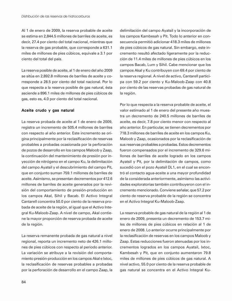
94 PEDESTRIAN AND STREETSCAPE GUIDE
and bus stops) are located. Table 37, on theprevious page, shows guidelines for new sidewalkinstallation according to the Federal HighwayAdministration (FHWA).
AccessibilityAll sidewalks and walkways should be accessibleand should comply with the ADA to themaximum extent feasible. Specific designrecommendations for accessibility of sidewalksand walkways are provided throughout thisToolkit section. Also refer to Toolkit Section 2 -Accessibility for more information about the ADArequirements and their relationship to design ofpedestrian facilities.
The Access Board recognizes that sidewalks aretypically constructed to match the grade of theadjacent street, which often exceeds that allowedby the ADA. The Access Board recommends thatevery attempt be made to meet accessibilityrequirements within the public rights-of-way,particularly in new construction, but allow thesidewalk to follow the grade of the adjacentroadway.
Recommended DimensionsIn general, the width of a sidewalk or walkwayneeds to comfortably accommodate the volume ofpedestrians normally using it. In high use areas,such as central business districts, sidewalks aregenerally 10 to 15 feet or wider to accommodatehigh pedestrian flows and to accommodate groupsof people traveling in opposite directions.Conversely, when excessively wide sidewalks arelocated in areas where there are low pedestrianvolumes, the expansive pavement and empty-looking sidewalks may seem uninviting topedestrians. The area exclusively used bypedestrians on the sidewalk should be at least 5feet, the amount of space for two people to passone another. The desirable minimum width is 6feet, since this creates a more comfortable widthfor two wheelchairs passing each other. Sidewalksshould NEVER be less than 3 feet, the required
amount for an accessible route (ADAAG 4.3.3,US Access Board, 1991). In 2001, the PublicRights of Way Access Advisory Committeerecommended 5 feet as the minimum width forthe pedestrian access route, with allowance forreduction to 4 feet for short distances. Signs andtrees branches should not protrude into thevertical clearance area (below 80 inches) of theentire public sidewalk.
The spatial dimensions of people provided in thesection of the guide called About Pedestrians canprovide some insight into how wide a pedestrianwalking area needs to be for a given number ofpeople. The width of sidewalks and walkwaysprovided may vary depending on pedestrianvolumes, the roadside environment and land usesetting, available space within the right-of-way,traffic characteristics, adjacent development, thecharacteristics of pedestrians using the facility,available funding levels, and local preferences.
Recommended dimensions for sidewalks andwalkways along various types of streets areillustrated in Table 38. The table referencescommon street system classifications and outlinesthe desirable and minimum dimensionsrecommended for sidewalks and walkways alongeach classification.
The dimensions listed in the table are guidelines.Dimensional requirements may vary within eachlocal jurisdiction. It is necessary to consider eachproject on an individual basis to determine thebest possible design solutions for pedestrians.For example, on a neighborhood collector thatprovides a high volume of pedestrian access toa school, park, or other popular destinations, itmay be desirable to provide wider sidewalks thanrecommended in the table.

95TOOLKIT 5–SIDEWALKS AND WALKWAYS
Passing, Waiting, andResting AreasPassing areas are required on all routes that areless than 5 feet wide. For more information, seeToolkit 2 - Accessibility.
Waiting and resting areas along walkways providewelcome relief to pedestrians, particularly thosewho have mobility impairments, or lack stamina.Figure 58 illustrates typical dimensions of waitingand resting areas adjacent to a walkway orsidewalk.
Grades, Cross Slope,and DrainageSidewalks and walkways should be designed withmaximum grades of 5 percent (1:20) wherepossible. The ADA encourages all pedestriantravel ways to be designed to not exceed thismaximum grade unless the adjacent road grade is
steeper and there is no other alternative alignmentfor the walkway. Since sidewalk grades aregenerally designed to match the adjacent streetsystem, it is recognized that in some cases it maybe necessary to exceed this gradient wheretopographic conditions and other physicalconstraints are severe.
Figure 58
Waiting and Resting Areas
Source: A Guide to Land Use and Public Transportation Volume II;Applying the Concepts
Recommended Dimensions for Sidewalks and WalkwaysRoad Type Principal Minor Collector Neighb. Local Commercial
Arterial Arterial Arterial Collector Residential AccessRight-of-Way 100 ft 84 ft 60 ft 60 ft 50-60 ft 60 ftWidth of Roadway 4 Lanes 4 Lanes 2 Lanes 2 Lanes 28 ft+ 44 ft+
Sidewalk WidthsNo buffer
Desirable 8 ft 8 ft 6 ft 6 ft 6 ft* 6 ftMinimum 6 ft 6 ft 6 ft 6 ft 5 ft* 6 ft
With planting strip/buffer 6 ft 6 ft 6 ft 5 ft 5 ft* 5 ft
With street trees, no buffer 10 ft 10 ft 8 ft 8 ft 5 ft* 5 ft
Urban Center/Business District 10-15 ft+ 10-15 ft+ Varies 5 ft 5 ft* 5 ft
Planting Buffer WidthWhen Used
Desirable 5 ft 5 ft 5 ft 5 ft 5 ft 5 ftMinimum 4 ft 4 ft 4 ft 4 ft 4 ft 4 ft
* Provide 6.5 ft minimum if mailboxes or other obstructions are located within sidewalk, so that a minimum clear width of 5 ft is provided.
Refer to local agency for specific design standards and requirements.
Source: This table was compiled from information in several documents (see Resource Guide)
Table 38

96 PEDESTRIAN AND STREETSCAPE GUIDE
Sidewalks are typically constructed with a crossslope of 2 percent (1:50) maximum, which is alsothe maximum allowed for accessible routes oftravel. The cross slope facilitates positive drainagetoward the street or adjacent planting buffer.
Drainage grates are best located outside the routeof pedestrian travel. If this is not possible, thegrate (as well as manhole covers, hatches, vaultsand other utility coverings) should not haveopenings greater than 0.5 inches in width andshould be mounted flush with the level of thesurrounding sidewalk surface.
Side Slopes, Railings,and WallsThe design of elements adjacent to sidewalks andwalkways can affect pedestrian comfort and safetyas much as the design of the sidewalks andwalkways themselves.
Side slopes next to sidewalks and walkways shouldgenerally not be steeper than 1:3. A level areaapproximately 4 feet wide minimum isrecommended for the sides of a sidewalk orwalkway. When a vertical drop is more than 30
inches/2.5 feet, exceeds a down slope grade of 1:2,and is located less than 4 feet from the edge of thewalkway, railing needs to be installed along theextent of the grade drop.
The recommended height for railings adjacent tosidewalks and walkways to provide protectionfrom vertical drops is 3.5 feet. Railings adjacentto multi-use pathways are also recommended tobe a minimum of 3.5 feet tall. For additionaldesign recommendations relatedto railings, refer to Toolkit Section 4 — Trailsand Pathways.
Vertical walls or retaining walls adjacent tosidewalks and walkways can be an imposing forceon passing pedestrians. Avoid high retainingwalls by terracing back on the slope with lowerwalls (when space is available in the right-of-wayor can be obtained). Minimize blank wall facesand design wall with an attractive finish andtexture or screened with trellises and climbingplants. Figure 59 illustrates suggested walldesign treatments.
Figure 59
Source: Adapted from City of Issaquah Urban Trails Plan (Non-Motorized Transportation), City of Issaquah
Wall Design Treatments
For tree planting and landscape requirements within state highway rights-of-way, refer to GDOT standards (MOG 6160)

97TOOLKIT 5–SIDEWALKS AND WALKWAYS
SurfacingAny material used for sidewalks and walkwaysneeds to be slip-resistant and easy to maintain(smooth for snow removal and able to resistbuckling and cracking). Surfaces must beaccessible, which is accomplished by meeting the“stable, firm, and slip-resistant” criteria of theADAAG design guidelines.
Sidewalks and walkways in urban areas aretypically constructed of Portland cement concrete(PCC), which provides a smooth, long-lasting anddurable finish that is easy to grade and repair.Scoring patterns may be designed to matchhistoric patterns within a neighborhood or districtwhere appropriate.
Asphaltic concrete pavement (ACP) can be used asan alternative to PCC, but it generally has ashorter life expectancy (15 to 20 years versus 40years for PCC). ACP is often used in low densityresidential areas or in less developed urban areas.Depending on the quality of design, construction,and drainage conditions, ACP sidewalks behindcurbs sometimes tend to settle and wear downfaster than PCC sidewalks. ACP is also moresusceptible to deterioration by vegetation andrequires more frequent maintenance. In areas,where walkways are aligned adjacent to shallow-rooted shrubs and trees, root damage to the
Special paving should be smooth to accommodate allpedestrians.
pavement can result. Root barriers can provide aneffective solution to this problem (see ToolkitSection 4 - Trails and Pathways).
Special districts and downtown streets oftenincorporate special paving into the design ofsidewalks and pedestrian areas, such as stamped orcolored concrete, brick, or other unit pavers.Brick and unit pavers need to be installed toprovide a smooth level surface. Special pavingbands that contrast with the sidewalk surfacingcan also be installed to alert pedestrians ofupcoming driveway crossings or as accents alongthe sidewalk. Refer to local governing agency forcurrent allowable material for sidewalks andwalkways.
The PROWAAC Building a True Communityreport includes guidance for creating “reducedvibration zones” along accessible routes, includingsidewalks and walkways. Refer to Toolkit 2 -Accessibility for more discussion.
In rural areas, alternative surfacing, such ascompacted crushed rock or unpaved compactedearth, may also be acceptable for certainwalkways. These surfaces are typically notaccessible to people using strollers or wheelchairsunless very smooth and well-compacted orstabilized. Recycled pavement grindings can alsoprovide an inexpensive surfacing material and areeasy to grade (especially during the summer whenthe heat helps pack and bind the material).
Sometimes sidewalks and walkways within theright-of-way are constructed as boardwalks withwood decking, as structures over elevation dropsor wet areas. Design considerations related toboardwalks and trestles are provided in ToolkitSection 7.

98 PEDESTRIAN AND STREETSCAPE GUIDE
Street Separationand Edge Treatments
Planting BuffersSidewalks alongside roadways are often separatedby planting strips consisting of natural vegetationor landscaping. Planting buffers (also referred toas planting strips, landscape strips or buffers, andnature strips) are generally considered to be a veryeffective separation treatment between walkwaysand streets in all types of settings. The addedseparation of a planting buffer helps a pedestrianfeel more comfortable when walking along thestreet. Planting buffers can be landscaped in avariety of ways to aesthetically enhance thestreetside environment. (Refer to Landscaping andStreet Trees.)
Planting buffers can be raised and bordered bycurbing, bermed, or developed at the same gradelevel as the roadway. It is recommended thatplanting buffers be a minimum of 5 feet in widthwhere street trees are proposed. (Check with localor state agency.) In areas where there is limitedspace or right-of-way, the width of the plantingbuffer can be reduced to a minimum of 2 feet inwidth, or eliminated and provided again wherethere is more space or right-of-way available.Figure 60 illustrates a planting buffer between asidewalk and street and Figure 61 illustrates aplanting strip as an area for signs, utilities, andfurnishings. Advantages and disadvantages relatedto the use of planting strips as a separationtreatment next to walkways are listed in Table 39.
Walkway along suburban street with planting buffer.
Advantages and Disadvantagesof Planting Buffers
Advantages
• Separation between pedestrians andstreet traffic
• Sidewalk can be at a more constant gradeacross driveways, avoiding dipping at everydriveway cut
• Area for drainage runoff and water qualitytreatment
• Space to locate street furniture, signs,mailboxes, parking meters and otherelements outside the clear space of thewalkway (see Figure 61)
• Aesthetic enhancement, increasing theappeal of the walkway and improving thepedestrian environment
• If wide enough, can be planted with largertrees that will provide shade and windprotection; 5 ft minimum widthrecommended for tree planting
• Typically a lower cost solution forseparation, if space is available
Disadvantages
• Maintenance is required, and variesdepending on the type of landscapingselected
• If not designed and maintained properly,landscaping may hinder visibility and causesecurity problems
• Root growth can sometimes damageadjacent paved surfaces if not protected
Table 39
Planting Buffer BetweenSidewalk and Street
Note: Trees in vehicular clear zone should have adiameter of not more than 4” measured 2’ aboveground.
Figure 60
For tree planting and landscape requirementswith state rights-of-way, refer to GDOT standards(MOG 6160)

99TOOLKIT 5–SIDEWALKS AND WALKWAYS
Clear Zone ConsiderationsAASHTO and GDOT (as well as most other stateDOTs) have specific requirements limiting lateralobstructions that can be potentially dangerous tomotorists who unintentionally leave the roadway.While planting buffers, poles etc. provide a levelof perceived security to pedestrians, they need tobe designed so that they do not create lateralhazards adjacent to the roadway. Therelationship of speed and lateral separationbetween a tree and the edge of pavement or face ofcurb are critical considerations.
GDOT has issued specific guidance for placementof street trees behind curb and gutter within theright of way for speeds up to 45 mph. Whereposted/design speeds are 35 mph or less, streettrees, poles, and other street furniture should belocated no closer than 3 feet from the face of curb.For posted/design speeds greater than 35 mphbut less than or equal to 45 mph, street trees,poles and other street furniture should be locatedno closer than 8 feet from the face of curb. Referto Figure 62 for specific dimensional requirementsfor street tree placement. Where the design speedor posted speed is over 45 mph, the clear zoneshould be determined from AASHTO guidelinesin the AASHTO Roadside Design Guide, 2002.Keep in mind that some factors may requireadditional offset from the edge of roadway/face ofcurb. These factors which include additionalanalysis include accident experience (type,locations etc.), number and location of driveways,
type of adjacent development, on street parking,bike lanes, and available right of way widths. Alsothe necessary sight triangles for motorists andpedestrians at side streets and driveways should beexamined and provided in the design.
In their Roadside Design Guide, AASHTO alsostates that trees cannot be located closer than 18inches from the face of curb, which is confusing tosome designers. It is referred to as the clear offset.This requirement is not a function of clear zoneconsiderations relating vehicle speed to offsetrequirements for safety purposes; it is simply anoperational offset for clearance for truck and busmirrors, bumpers, overhangs, and otheraccessories that project beyond the wheelbase ofthe vehicle.
Meandering WalkwaysSometimes, a meandering walkway is constructed,creating a planting strip with an informal, curvingappearance. Although meandering walkways maylook nice, they are not the most efficient way ofgetting people from one place to another. Theymay also be misguiding to pedestrians with sightimpairments who need better predictability.
If a meandering walkway is desired, minimize thenumber of curves to avoid creating a route that istoo awkward and indirect. Meandering walkwayscan provide the advantage of design to avoidobstacles such as telephone poles, utility features,signs, etc. Figures 63 and 64 illustrate a straightwalkway and a walkway with a slight meander.
Ditches or Swales as SeparationOn many rural roadways, an open ditch is locatedalong the edge to provide conveyance andtreatment of stormwater runoff. Where there issufficient space within the right-of-way, thesidewalk or walkway can be located behind theditch, providing a buffer area between motorvehicle traffic and pedestrians. In situationswhere a ditch or swale is used to separate asidewalk, the separation area needs to be aminimum of 5 feet wide. A sidewalk separated
Figure 61
Planting Strips Provided as Area forSigns, Utilities, and Street Furnishings
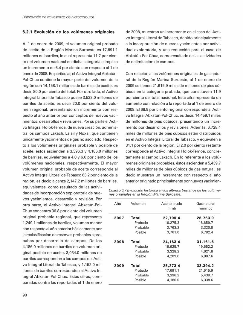
100 PEDESTRIAN AND STREETSCAPE GUIDE
Figure 62
Speed Design/Posted Speed < 35 mph
35 mph < Speed Design/Posted Speed < 45 mph

101TOOLKIT 5–SIDEWALKS AND WALKWAYS
from the roadway by a swale is illustrated in Figure65.
Curb and Gutter / Vertical CurbCurb and gutter provides two primary functions:control of stormwater drainage, and verticalseparation between motor vehicles and pedestrians.Curbs are often required on streets with highervolumes and speeds and where efficiently controlleddrainage is a necessity. Curb and gutter or verticalcurb are commonly required for urban streets.
Curb and gutter and vertical curb provide a non-mountable barrier adjacent to street parking thatkeeps cars from parking on adjacent sidewalks.Curbs provide a perceptive separation betweenmoving vehicles and pedestrians. Curbs can becostly to construct, so they may not be practical tobuild in all areas. Curbs also have an urban-lookingappearance, which may not be desirable in someareas, where a more natural-looking roadsideappearance is desired. Figure 66 illustrates asidewalk adjacent to curb and gutter, and Figure 67illustrates a vertical curb adjacent to a planting.
Rolled Curb (Strongly Discouraged)Rolled curb is a mountable type of curb designoften used in suburban neighborhoods. Rolledcurb provides an advantage in that it eliminates theneed for individual driveway cuts, however, it oftenpresents a problem when used along sidewalks.Since rolled curbs are easily mountable by motorvehicles, drivers often park up on top of the curband block the sidewalk. Additionally, theeffectiveness of rolled curbs as a barrier is less thanvertical curb between pedestrians and vehicles.Figure 66 illustrates a sidewalk with rolled curb.Rolled curb also needs to be converted to a verticalcurb at the curb ramp to provide a message to blindpedestrians.
Vertical curb or curb and gutter constructed usingstandard designs provide a barrier adjacent tosidewalks that is more desirable than rolled curbadjacent to pedestrian travel ways.
Figure 63
Figure 64
Figure 65
Sidewalk Separated by a Swale
Straight Walkway
Meandering Walkway
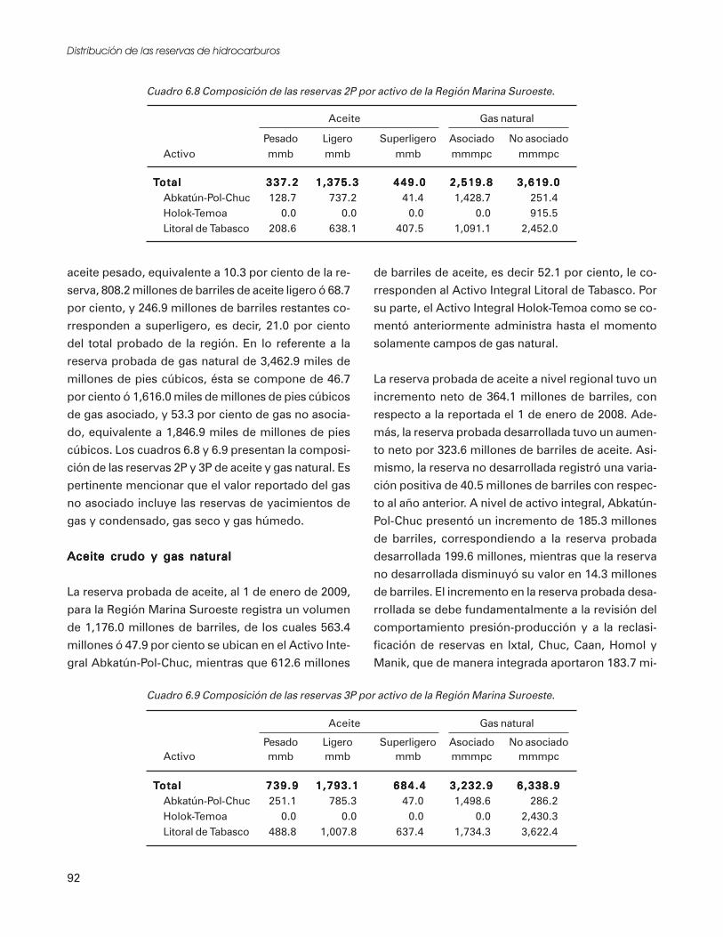
102 PEDESTRIAN AND STREETSCAPE GUIDE
Raised Pavement Markers (StronglyDiscouraged)Raised pavement markers are small plastic devicesthat are glued to the pavement surface as adelineation technique at the edge of roadways.
Raised pavement markers used adjacent to bicyclelanes are strongly discouraged, particularly as adelineation device between vehicle lanes and bicyclelanes. They create potential bicycle wheel deflectorsand are particularly hazardous when they are wet,which makes small width bicycle tires slip and cancause loss of control of the bicycle. If they are used,they should be placed as far apart as practical, thusreducing their exposure to bicycle tires.
They should only be used as delineators at locationswhere an engineering study has determined thatmarkers are essential to preserving pedestrian,bicycle, and motor vehicle safety. At the initiationof the engineering study, local bicyclingorganizations and the state bicycle coordinatorshould be notified for review and comment.Existing raised pavement markers that interfere withbicycle travel should be removed at the timeroadways are being resurfaced.
Use of raised pavement markers for conventionalmotor vehicle lane delineation should be done inaccordance with MUTCD and state and localstandards.
Bike Lanes as SeparationWhen bike lanes are located between the street andthe pedestrian travel way, they providea buffer between pedestrians and motor vehicles. Itis recommended that the width of the bike lanecomply with GDOT guidelines. The adjacentpedestrian travel way should be raised and separatedby curb (in urban areas), or at a minimum, a whiteedge stripe should be used at the outside edge,between the bike lane and the shoulder area to beused by pedestrians (in rural areas). Figure 69illustrates how a bike lane provides an additionalbuffer between pedestrians and motor vehicles.Figure 68
Sidewalk With Rolled Curb
Rolled curb is undesirable because vehicles can park onsidewalk, blocking pedestrian travel.
Sidewalk Adjacent toCurb and Gutter
Figure 66
Figure 67
Vertical Curb Adjacentto a Planting Strip

103TOOLKIT 5–SIDEWALKS AND WALKWAYS
Concrete BarriersConcrete barriers (also called New Jersey barriers)are occasionally used as a protective separationdevice between roadways and pedestrian travelways, although their primary purpose is to shieldand direct vehicles away from potential hazards.According to AASHTO, concrete barrier heightshould be a minimum of 32”.
Concrete barriers cost significantly more thancurbing, and may not be the most visuallyappealing solution. They also are less attractivethan other buffering/separation treatments whenconcrete barriers are used for separation betweenroadways and pathways. Check with local andstate design requirements for end treatments.The ITE manual, Design and Safety of Pedestrian
Facilities, provides some guidance about when it isnecessary to provide pedestrian barriers.
Vertical concrete surfaces adjacent to pedestrianfacilities should be smooth to avoid snagging ofclothing or abrasive injuries from contact with thesurface. Bolts or other protrusions from walls,railings, or barriers need to be cut off flush to thesurface or recessed.
Street Furnishings, Utilities,and Related ClearancesUrban streetscapes should be carefully designed inorder to provide adequate space for furnishingsand utility facilities, outside the main travel wayused by pedestrians. A clear travel way of 5 feetminimum is recommended for all sidewalks andwalkways in the public right-of-way and 3 feetminimum is required by ADAAG for all accessibleroutes of travel within Title III sites. Thisclearance is only suitable where pedestrianvolumes are low. Where pedestrian volumes aremoderate to high, this clearance should beincreased to the maximum obtainable or the fullwidth of the sidewalk. Obstacles, such as signs,street furniture, and newspaper stands, should beplaced off to the side of the travel way, in the“fixtures/planting zone,” as discussed later in thistoolkit.
The vertical clearance needed for sidewalks andwalkways is typically 7 feet, as illustrated inFigure 70. The ADAAG requires that “objectsprotruding from walls (e.g., signs, fixtures,telephones, canopies) with their leading edge between27 and 80 inches above the finished sidewalk shallprotrude no more than 4 inches into any portion ofthe public sidewalk.” Traffic signs located directlyadjacent to or within the sidewalk need to bemounted and tree branches need to be prunedhigh enough so that there is a minimum of 7 feetof clearance from ground level. Informational anddirectional signs for pedestrians can be lower, iflocated a minimum of 3 feet from the sidewalk. Atypical pedestrian travel way, designed to be clear
Figure 69
Bike Lane as Buffer BetweenPedestrians and Motor Vehicles

104 PEDESTRIAN AND STREETSCAPE GUIDE
Figure 70
Clearances for Sidewalks and Walkways
Figure 71
Pedestrian Travel Way, Clear of Obstructions

105TOOLKIT 5–SIDEWALKS AND WALKWAYS
of obstructions, is illustrated in Figure 71, on theprevious page.
Landscaping and Street TreesThe use of planting buffers for separation betweenwalkways and streets was discussed previously inthis Toolkit. Landscaping and street trees inplanting buffers and along streets can greatlyenhance the pedestrian environment and provideshade and shelter, but careful thought needs to begiven to the selection of trees and shrubs to beinstalled.
Using low height shrubs and upward branchingtrees will maintain visibility and sight distance atintersections, driveways, crossings, and othercritical areas along the street system. It is alsoimportant to consider how high and wide theshrubs and trees will be at maturity.
Street trees are typically spaced evenly along thestreet, ranging from 25 to 50 feet apart,depending on the size of the tree at maturity.Trees can also be placed informally and clusteredin areas. Do not locate trees where they will bean obvious obstruction to visibility. Utilities,whether above or below ground, are important toconsider when determining if a tree isappropriate, the type of tree to plant, and its
location along a street. Provisions on street treesneed to comply with the discussion in “ClearZone Considerations” section.
Selection of plant material also needs to considerthe availability of irrigation water, ways tominimize maintenance, and communitypreferences for landscape materials (such as the useof native species and informal plantings versusornamental or formal landscapes).
When tree wells are installed on urban sidewalks,they should be placed out of the pedestrian travelway. Tree wells can vary in size depending on thewidth of the sidewalk (refer to Figure 62). Treegrates adjacent to or within sidewalks need tomeet the accessibility requirements of the ADA -top mounted flush with grade and no openingslarger than 0.5 inches in diameter.
For all tree plantings and landscape requirementswithin state highway rights-of-way, refer toGDOT standards (MOG 6160) and the “ClearZone Considerations” section. For all otherrights-of-way, refer to local jurisdiction standards.Additional design guidelines related tolandscaping adjacent to pedestrian facilities,including recommendations to minimize rootdamage to adjacent paved areas, are provided inToolkit Section 4 - Trails and Pathways.
LightingLighting of the street system, including adjacentsidewalks, walkways, and bike lanes, increasessecurity and pedestrian safety and comfort.Typically, the street lighting system in urban areassufficiently serves pedestrian sidewalks andwalkways along the street. It’s important toconsider the security and comfort of pedestrians,when designing a street lighting system.
Where a new lighting system is being introducedeither to replace or supplement the existing streetlighting system, it may be possible to incorporatelight posts and fixtures that are more pedestrianfriendly (shorter and more in scale with
Street trees enhance pedestrian environments.

106 PEDESTRIAN AND STREETSCAPE GUIDE
pedestrians and with less obtrusive and harshlight sources). Additional lighting may benecessary at pedestrian crossing points,intersections, entrances to buildings, and otherareas to supplement existing street systemlighting.
It is generally recommended that a level oflighting between 0.5 and 2.0 footcandles beprovided along pedestrian travel ways, dependingon conditions. Check with your local agency forapplicable design standards. Also, refer to thestandards and design guidelines of theIlluminating Engineering Society of NorthAmerica and GDOT’s policies.
SigningPedestrian facilities generally require minimalsigning. Most regulatory and warning signs aredirected at motor vehicle traffic along streets andprior to crossings. Directional and informationalsigning installed for motor vehicle use may notadequately serve pedestrians, so care should betaken to identify key origins and destinations,such as schools, parks, libraries, museums,entertainment centers, and shopping districts.
Distances to these origins and destinations can begiven in blocks, average walking time, or othermeasurements meaningful to pedestrians. Theprovision of walking maps, including informationabout transit routes, make it easier for pedestriansto find their way around a new urbanenvironment. Some cities and towns haveprovided maps inscribed in the sidewalk or onmanhole covers. Information for pedestrians canalso be displayed on kiosks or other designatedareas.
Signs should be easy to read and understand withsimple phrases and graphics. Letters and symbolsneed to be bold with high contrast to thebackground. Generally, light letters and symbolsagainst dark backgrounds are easiest to read.
Signing needs to be understood by the vastmajority of the population, including non-English speaking people and children. The use ofinternationally recognized symbols can be aneffective way to identify features to all pedestrians.
Historic DistrictsMany times sidewalks in historic districts includebrick or cobblestone that make it difficult andunsafe for pedestrians with mobility impairmentsto travel. It is difficult and painful for wheelchairriders to travel over these pavement types. Thereare several alternatives to cobbles and brick thatcan be used without compromising the design ofthe sidewalk.
• Brick or cobbles can be used as an edge to aconcrete sidewalk. This preserves some historicdesign without compromising the travelexperience for ALL pedestrians.
• The use of colored and/or stamped concrete (invarious patterns) also creates a betterenvironment, although, if used, the designneeds to be provide a “reduced vibration zone”(refer to Toolkit 2 - Accessibility.)
• To maintain the character of historic districts,existing surface material can remain if additionalpaths of smoother material are added.
Pedestrian scale lighting
107TOOLKIT 5–SIDEWALKS AND WALKWAYS
Figure 72
• Flat pavers or bricks that are butted directlytogether without joints can create a smoothsurface, but the base design and constructionmust be of the highest quality to ensure that aconsistent surface results.
Sidewalks in BusinessDistricts and DowntownsSidewalks in central business districts anddowntown areas need to be designed to efficientlyaccommodate heavy volumes of pedestrian traffic.Streetscapes in these areas often function formultiple purposes, and the streetside generallyconsists of three zones: the building frontage zone;the pedestrian travel zone; and the fixtures/planting zone. These three zones and their typicalapproximate widths are illustrated in Figure 72.Please note that these widths may vary and may bewider, depending on specific circumstances withinthe right-of-way.
Building Frontage ZoneThe building frontage zone is the area wherepeople enter and exit buildings adjacent to thestreet right-of-way. People don’t feel comfortablemoving at full pace directly adjacent to thebuilding wall, so this area is to the side of theprimary travel area. It is also an area wherepedestrians may window shop or move moreslowly, restricting other pedestrians. On somestreets, the building frontage zone may become apedestrian plaza, outdoor cafe, or gathering area infront of some buildings, depending on availablespace within the right-of-way. For this reason, thebuilding frontage zone can vary in width fromapproximately 2 to 10 feet or more. At aminimum, people prefer about 2 feet of “shy”distance when walking adjacent to buildings, asillustrated in Figure 73.
Pedestrian Travel ZoneThe pedestrian travel zone is the central area wheremost pedestrians travel on the downtown sidewalk.It is desirable to provide the widest possible clearspace for pedestrian travel, particularly in urban Figure 73
Shy Distance Between Buildingand Walkway
Urban Streetside Zones

108 PEDESTRIAN AND STREETSCAPE GUIDE
areas where there are higher volumes ofpedestrians. The pedestrian travel zone ondowntown streets should typically be 6 to 10 feetwide or greater in areas where high volumes ofpedestrians are anticipated. Within this area, aminimum 5-foot wide accessible route must beprovided.
Fixtures/Planting ZoneThe fixtures/planting zone is located directlyadjacent to the street and provides a bufferbetween the street traffic zone and the pedestriantravel zone. Consolidate or congregate, wherepossible, utilities, street furniture, and otherelements within the fixture/planting zone tominimize obstacles in the pedestrian travel wayand improve the visual appearance of an area.Examples of consolidating include putting morethan one utility on a pole system or more thanone sign on a post, and clustering furnishingswithin the planting strip or to one side of theprimary walking area. The approximatedimension for the fixtures/planting zone istypically 3 to 10 feet (minimum 4 feet, if trees areinstalled) depending on the dimensions of theright-of-way and the street traffic and thepedestrian travel zone. Curb extensions provideopportunities to place benches and furnishings.
On some urban streets with limited right-of-way,it may be necessary to reduce the widths of thebuilding frontage and fixtures/planting zones, oreliminate them altogether. Providing a pedestriantravel zone with a minimum width of 6 feet isrecommended in this case. Trees and fixtures thatcould conflict with vehicle entry and exit shouldbe located between parallel parking spaces.
Shoulders as Walkwaysin Rural AreasWide shoulders along roadways can also functionas walkways, particularly in rural areas. Localagencies sometimes consider paved or unpavedwalkways and roadside shoulders used forpedestrian travel in urban areas to be interimsolutions until funding permits construction offull sidewalk improvements. In rural areas, wherefunding for pedestrian improvements can belimited, walkways and shoulders may beacceptable as a longer-term solution, particularlyif the alternative is no pedestrian facilities at all.In any case, local agencies should considerconstruction of sidewalks or pathways alongsections of roadway where shoulders are beingregularly used by pedestrians.
Recommended Shoulder DimensionsA 3 to 5-foot wide shoulder adjacent to a bikelane and on local roads with lower traffic volumes(less than 400 ADT) may provide a sufficientwalking space for a single pedestrian. Butshoulders that accommodate groups ofpedestrians, such as school children walking toand from school, and that are located on majorcollectors and arterials (with more than 2,000ADT) should to be wider or should include asidewalk behind a curb and gutter. Given thestipulated ADT and use by large groups ofchildren, suitable wider sidewalks and/or plantingbuffers may be desirable.
At a minimum, shoulders at least 5 feet wide onboth sides of the road for school walk routes or atleast 8 feet wide if constructed on only one side
Streetscapes in downtowns need to be designed toaccommodate heavy volumes of pedestrians.

109TOOLKIT 5–SIDEWALKS AND WALKWAYS
are recommended. Shoulder areas located atschool bus stops need to be widened toaccommodate children waiting at the roadside forthe bus (refer to Toolkit Section 3 - Children andSchool Zones).
In rural areas with heavy pedestrian use, anadditional pavement width should be consideredto obtain wider shoulders. Local standards forshoulder widths may vary. A typical walkingshoulder is illustrated in Figure 74.
Shoulder Surfacing and DelineationShoulders may be paved or unpaved. A highvisual and tactile contrast is desirable in order toclearly define the pedestrian area and discouragedrivers from straying onto the shoulder. If pavedshoulders are to be used by pedestrians, theyshould be well-marked. One design solution thathelps delineate the shoulder walking area is theuse of a contrasting paving material or color forthe paved shoulder, or a contrasting stripseparating the shoulder from the street.
Shoulders for walking may also be delineated by a5-inch wide white strip at the edge of thevehicular travel lane or bike lane. Alternativestriping solutions may also be acceptable, such aswider than standard white fog lines or edge
stripes, dashed stripes, angled stripes, and othertechniques.
Raised pavement markers are generally notrecommended as an edge line delineationtreatment because they create an obstacle tobicycle travel (see discussion earlier in thistoolkit). Pavement texturing techniques, such aschip seal markers, can be used to delineateshoulders and provide both a tactile and audiblewarning to pedestrians and motorists.
Unpaved shoulders consisting of a compacted,stable surface can also be installed and offer acontrasting material adjacent to asphalt orconcrete roadway paving. Compacted earth orlow-growing grass shoulders can also provide awalking area for pedestrians, but they functionpoorly during wet weather. Unpaved shoulderscan be less costly to install, but are usually morecostly to maintain.
Operational Considerations Related toShouldersShoulders are not an ideal travel route (see Toolkit2 - Accessibility). In areas where an accessibletravel route is needed along the roadside toprovide access between public buildings or
Figure 74
Shoulder Walkway
Shoulder walkway in rural area.

110 PEDESTRIAN AND STREETSCAPE GUIDE
facilities, a full sidewalk or walkway improvement,raised and separated from the street, should beconstructed.
Shoulders that are intended to be used bypedestrians should not be used as roadsideparking lanes, not even for short-term ortemporary periods (except during emergencies).
Shoulders that are heavily relied upon by pedestriansfor a regular walking route will not functionadequately if they double as bike lanes. Separatebike lanes are recommended. If a multi-use pathwayis to be provided within the right-of-way, itshould be designed to meet or exceed AASHTOstandards (see Toolkit 4 - Tails and Paths).
Table 40 summarizes a few of the importantconcerns related to roadside shoulder design forpedestrian use.
Bicycles on SidewalksGenerally, designating sidewalks for bicycle travelis not recommended even if the sidewalks arewider, for the following reasons:
• Motorists do not expect to see bicycliststraveling on sidewalks and may pull out ofintersections or driveways and unexpectedlycollide with a bicycle.
• The potential for conflicts between bicyclists andpedestrians greatly increases with shared use.
• Pedestrian movements are often unpredictablefor an approaching bicyclist from behind(especially those of small children), andpedestrians cannot always predict the directionan oncoming bicyclist will take.
• Sidewalks are usually two-way facilities andbicyclists are encouraged to travel one-way, withthe flow of traffic.
• Sight distances are more limited at drivewaycrossings.
• There also may be limited sight distance andclearances due to signs, utilities, landscaping,fencing, or other obstacles beside or protrudinginto the sidewalk.
Bicycling on sidewalks is discouraged, but notprohibited by state law. Local requirements mayprohibit bicycling on sidewalks.
Street Design ConsiderationsSince sidewalks and walkways are developed asintegral components of street and roadwaysystems, there are several important aspectsrelated to street design that affect pedestrians.
Recommendations forWalking Shoulders
• Best used in rural areas with lower
pedestrian volumes (to be used
infrequently)
• 3 to 5 feet wide for roadways with less
than 400 ADT
• 5 feet minimum, both sides for school
walking routes
• 8 feet minimum, at least one side for
school walking routes and roadways with
over 2,000 ADT
• Can be paved or unpaved, but high visual
and tactile contrast from adjacent roadway
is best
• Sign to prohibit parking
• Double use as bike lanes not recommended
(unless designed as a multi-use facility in
accordance with local, state, and federal
standards)
Table 40
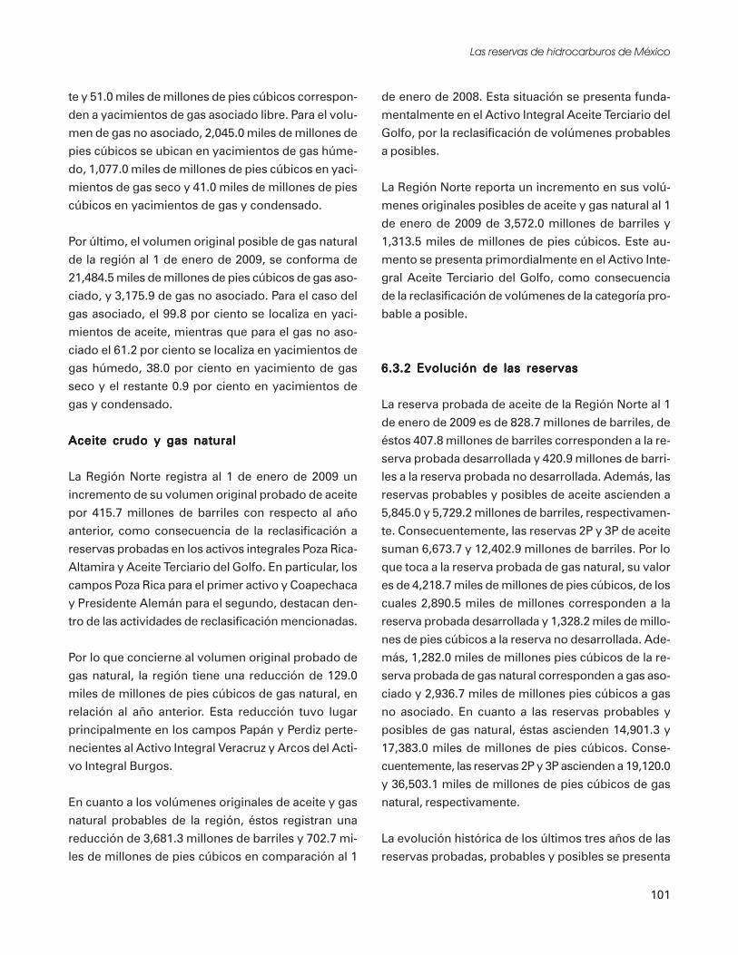
111TOOLKIT 5–SIDEWALKS AND WALKWAYS
Figure 75
On-Street Parking as a Buffer BetweenStreet and Pedestrian Walkway
Parking Along StreetsOn-street parking provides a buffer zone betweenthe roadway and the sidewalk. It also narrows theappearance of streets, reducing vehicle speeds.On-street parking provides opportunities forpeople to access the sidewalk directly from theirvehicles and increases street activity. For thesereasons, on-street parking is often supported inbusiness and shopping districts, neighborhoods,and other urban areas. Figure 75 illustrates howon-street parking provides a buffer between streettraffic and pedestrians.
In some cases, on-street parking may presentproblems when there is not enough space forpeople to safely get out of their cars or walkbetween cars. On-street parking on roadwayswhere there are no adjacent pedestrian facilities orundelineated crossings is not desirable becausepedestrians may be forced to walk in the roadwayto get to their destination or may cross at severalpoints along the roadway rather than at a singlepoint. A common cause of collisions is the lack ofvisibility of pedestrians entering the roadway frombetween parked cars. An example of this is whenon-street parking is provided informally adjacentto a park or ballfield where there are highnumbers of children prone to darting out intostreets and not aware of traffic conditions.
Parallel parking stalls need to provide adequatespace for pedestrian movement around the parkedcar without forcing pedestrians out into thestream of traffic and to prevent car doors fromopening into bike lanes. Typical dimensions of 9feet wide by 24 feet in length (provides space inbetween cars) are recommended for on-streetparallel parking stalls (although practice allows asnarrow as 7 feet and as short as 22 feet, checklocal standards). In cases where a bike lane islocated adjacent to parallel parking, the bike lanewidth should be at least 5 feet to provideadditional maneuvering space.
When on-street parking is provided, adjacentpedestrian walkways and clearly identified street Angled on-street parking

112 PEDESTRIAN AND STREETSCAPE GUIDE
crossing points are also necessary. On-streetparking or loading zones that are too close tointersections and mid-block crossings can blockviews of pedestrians. Parking areas should be setback from intersections and crossings to allowpedestrians to see oncoming traffic. Refer toToolkit Section 6 - Intersections, forrecommended set back distances for on-streetparking near pedestrian crossing points. Fencingcan be installed to channelize pedestrians tocrossing points at specific entrances, but it shouldbe designed and placed carefully so as not tobecome an obstacle to pedestrian travel. Bulb-outs and curb extensions also help to definepedestrian crossing points.
When perpendicular parking stalls are locatedadjacent to sidewalks, wheel stops or curbingshould be constructed to eliminate vehicleoverhang that reduces usable sidewalk area.Figure 76 illustrates this treatment.
Access Management and DrivewaysMost pedestrian/motor vehicle collisions on busystreets occur at points of intersecting movements,such as intersections, driveways, and alleys.Unlimited vehicle access on roads increases thelevel of conflicts between pedestrians walkingalong the roadway and cars entering or leaving theroadway. Pedestrians crossing the roadway needgaps in the traffic stream, but with unlimitedaccess, vehicles entering the roadway quickly fillthe available gaps. Pedestrian access to transitmay also be complicated by excessive driveway
access points creating obstacles on their way tothe bus stop.
Table 41 lists access management techniques aswell as several benefits for pedestrians that resultfrom access management. Figure 77 illustrateshow controlled access and limited drivewaysreduce conflict points between pedestrians andmotorists. The level of access management and itsrelationship to providing pedestrian facilitiesalong state highways is described later in thissection.
Driveways that cross sidewalks and walkways needto be carefully designed to minimize conflictsbetween pedestrians and vehicles. For designrecommendations related to driveway design (forboth commercial and residential sites), refer toToolkit 10 - Site Design for Pedestrians.
Access to TransitThe level of transit use often depends on theextent of improvements provided for pedestrians.Transit stops are provided in both urban andrural areas, and often pedestrians rely heavily ontransit as their primary mode of transportation.Sidewalks, walkways, crossings, and otherpedestrian facilities adjacent to and near transitstops need to be carefully planned and welldesigned as a collaborative effort between thetransit agency and the public works and trafficengineering departments of the local jurisdiction.Design recommendations related to transit stopsand facilities are provided in Toolkit Section 9 -Pedestrian Access to Transit.
Benefits and Disadvantages ofOne-Way Streets for PedestriansOne-way streets can provide certain benefits topedestrian travel if appropriately implemented.However, when they are designed to increasetraffic speeds, they can create an unfriendly anduninviting environment for pedestrians. Some ofthe benefits and disadvantages related to the useof one-way streets are described in Table 42.
Figure 76
Parking Overhang
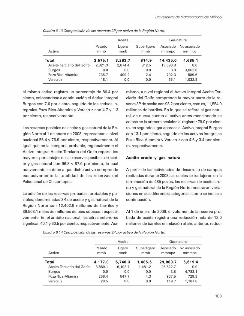
113TOOLKIT 5–SIDEWALKS AND WALKWAYS
Access ManagementTechniques• Reducing the number of existing driveways or consolidating driveways to parking areas and businesses
• Providing raised or landscaped medians or concrete barriers to control turning movements from the street(with these treatments, it is important to provide accessible pedestrian crossing opportunities with breaks inthe medians or barriers at suitable crossing points)
Benefits• The number of conflict points is reduced (particularly with the use of center medians to reduce the
number of conflicts between left-turning vehicles and pedestrians.)
• Pedestrian crossing opportunities are enhanced with an accessible raised median and fewer conflicts withturning cars.
• Accommodating people with disabilities becomes easier with the reduced need for special treatments atdriveway cuts.
• Traffic volumes may decrease if local traffic can use other available routes (but also note that volumes mayincrease if the route becomes more efficient for vehicles to use.)
• Improved traffic flow may reduce the need for road-widening, allowing more space within the right-of-wayfor use by pedestrians, bicyclists, and enhancements and maintaining fewer travel lanes to cross at
intersections.
Source: Adapted from Oregon Bicycle and Pedestrian Plan
Table 41
Figure 77
Access Management
Excessive access points require
pedestrians to cross ingress/egress
traffic more than necessary.
Reducing the number of access
points improves safety and
comfort for pedestrians.
Source: Adapted from Oregon Bicycle and Pedestrian PlanFor tree planting and landscape requirements within state highway rights-of-way, refer to GDOT standards (MOG 6160)

114 PEDESTRIAN AND STREETSCAPE GUIDE
When considering conversion to a one-waystreet system, communities need to consider allthe potential implications. Additionalinformation that may be helpful tocommunities in considering whether or not toconvert to a one-way street system is available inthe Florida Pedestrian Planning and DesignGuidelines and the ITE Traffic EngineeringHandbook.
Benefits and Disadvantages of One-Way Streets
Benefits for Pedestrians
• One-way streets in downtown areas or
elsewhere, where practical, may be helpful
to pedestrian travel because pedestrians
have to watch traffic from only one
direction when crossing.
• May also allow more space within the right-
of-way in certain cases, creating more areas
for pedestrians, parking, and other purposes.
• Can create smaller block patterns and
allows reduced curve radii on corners
where vehicular turning traffic doesn’t
occur, which equates to shorter crossing
distances for pedestrians.
• Improved signal timing because one-way
streets can create consistent signal spacing
(so pedestrians may walk at a continuous
pace between intersections; but this can be
a disadvantage in that it may speed traffic).
Disadvantages for Pedestrians
• Vehicles are likely to travel faster if the
travel lanes are wide or there are multiple
lanes.
• May adversely affect transit operations and
transfer opportunities.
• May change character of downtowns.
Table 42 Main street through small town
Pedestrian Facilities Along StateHighways
State Highways as Main StreetsIn many small towns and cities, state highwaysserve as the main street and primary arterialthrough the center of town. They function as themajor route into which local arterials andcollectors feed. In some smaller cities and towns,the state highway is often the only arterialconnecting virtually all major destination points.
The provision of adequate pedestrian facilitiesalong the state highways in these settings is acritical component to incorporating pedestriansinto the overall transportation network. Sidewalksfor these main streets need to be designed thesame as they would be for the urban centers oflarger cities — able to support heavy pedestrianuse. (Refer to specific design recommendationsearlier in this toolkit section, including thediscussion on Sidewalks in Business Districts andDowntowns.) It is important to remember thatthere are differences between the small town mainstreet environment and the larger city street

115TOOLKIT 5–SIDEWALKS AND WALKWAYS
environment, and applied design treatmentsshould consider community preferences such asenhancements that reflect historic character orlandscape themes.
State Highways as Connectors Between Townsand CitiesProviding sidewalks and walkways along sectionsof state highways that connect urban or suburbancenter should be considered. Along their length,they have potential trip generators, such asschools, parks, scenic stops, and residential andcommercial areas within proximity to oneanother.
MaintenanceClear, smooth, level surfaces are essential forpedestrians and particularly for people in
wheelchairs, older adults, and young children.Vertical movement and cracking are commonproblems that could create hazards. Drainagesystems should be kept in good working order toavoid accumulation of water over pedestrianwalking areas. Table 43 outlines sidewalkconcerns and maintenance measures to ensurethat sidewalks adequately serve pedestrians overthe long term.
Construction and installation of utilities shouldbe coordinated between the utility company andthe governing authority with jurisdiction over thestreet system. Interruptions to pedestrian travelneed to be minimized and construction shouldavoid damage to pedestrian facilities. In somecases, it may be possible to improve conditions forpedestrians as part of an overall utility project.
Maintenance Recommendations for Sidewalks
Concern Maintenance Activity
Tree roots cracking and Remove failed sidewalk, cut roots and install new sidewalk. A local arborist should beheaving sidewalk contacted prior to removing large roots
Section pop-up of vertical height Replace defective sections or provide temporary asphalt shim.greater than ½ inch
Cracked or spalling surface and Replace defective sectionspoorly placed temporary patching
Separation of expansion and Fill joint with hardening expansion compoundconstruction joints so that spacebetween adjoining sections aregreater than 1/4 inch
Trash, loose sand, oil and grease Serve notice to abutting landowners to clean and maintain sidewalks.on walkways and sidewalks
Materials, signs, vending Require responsible parties to remove obstructionsmachines, etc. restrictingeffective sidewalk width
Low hanging tree limbs, bushes, Enact and enforce local regulations requiring abutting land users to perform timely clearanceweeds, and other foliage growing activity. Hire private contractor to clear sidewalk and assess cost to abutting land users.into the sidewalk and/orposing obstructions
Source: New Jersey Department of Transportation - Pedestrian and Design Guidelines
Table 43

116 PEDESTRIAN AND STREETSCAPE GUIDE
Such a project may create the opportunity torelocate a utility pole or box outside thepedestrian travel way. Also, refer to Toolkit 11-Safety in Work Zones, for more information.
Other Sources of InformationThe following sources of information arerecommended for design of sidewalks andwalkways. Please see the Resource Guideincluded at the end of this guide for completebibliography information.
A Guide to Land Use and Public Transportation,Volume II: Applying the Concepts, The SnohomishCounty Transportation Authority
A Guidebook for Student Pedestrian Safety, FinalReport, KJS Associates Inc.
A Policy on Geometric Design of Highways andStreets, 1994, American Association of StateHighway and Transportation Officials
A Working Approach to Accessibility in Public Rightsof Way, Montana Department of Transportation
Accessible Sidewalks: A Design Manual, USArchitectural and Transportation BarriersCompliance Board (The Access Board)
Accessibility Design for All, An Illustrated Handbook,1995 Washington State Regulations, Barbara L.Allan and Frank C. Moffett, AIA, PE
Accommodating the Pedestrian, Adapting Towns andNeighborhoods for Walking and Bicycling, RichardK. Untermann
Americans With Disabilities Act (ADA) AccessibilityGuidelines for Buildings and Facilities; State andLocal Government Facilities; Interim Final Rule,Federal Register, Part II, Architectural andTransportation Barriers Compliance Board
“Boulder Brings Back the Neighborhood Street,”John Fernandez, Planning
City Comforts, How to Build An Urban Village,David Sucher
City of Issaquah Urban Trails Plan (Non-MotorizedTransportation), City of Issaquah
City, Rediscovering the Center, William H. Whyte
Design and Safety of Pedestrian Facilities, A ProposedRecommended Practice of the Institute ofTransportation Engineers, ITE Technical CouncilCommittee 5A-5
Design Guidelines, Building/Sidewalk Relationships,Central Business District, City of Bellevue
Design Manual, 1020 Facilities for NonmotorizedTransportation, Washington State Department ofTransportation
Effects of Site Design on Pedestrian Travel in Mixed-Use Medium Density Environments, Anne Vernez-Moudon, PhD
Engineering Design and Development Standards,Snohomish County Public Works
Florida Pedestrian Planning and Design Guidelines,University of North Carolina
Great Streets, Allan B. Jacobs
Handbook of Landscape Architectural Construction,Volume Two, Site Works, Maurice Nelischer
Handbook for Walkable Communities, WashingtonState Pedestrian Facilities Planning and DesignCourses, Dan Burden and Michael Wallwork, PE
Livable Neighborhoods: Rethinking ResidentialStreets, American Public Works Association andthe University of Wisconsin-Madison

117TOOLKIT 5–SIDEWALKS AND WALKWAYS
Livable Streets, Donald Appleyard
Manual on Uniform Traffic Control Devices froStreets and Highways, 1988 Edition, USDepartment of Transportation
Pedestrian Malls, Streetscapes, and Urban Spaces,Harvey M. Rubenstein
Planning and Implementing Pedestrian Facilities inSuburban and Developing Rural Areas ResearchReport, S.A. Smith, K.S. Opiela, and L.L. Impett
Planning Design and Maintenance of PedestrianFacilities, Goodell-Grivas, Inc.
Public Streets for Public Use, Anne Vernez Moudon
Reclaiming Our Streets, Traffic Solutions, SaferStreets, More Livable Neighborhoods, CommunityAction Plan To Calm Neighborhood Traffic,Reclaiming Our Streets Task Force
Redevelopment for Livable Communities,Washington State Energy Office, the WashingtonState Department of Transportation, theDepartment of Ecology, and the Energy OutreachCenter
Residential Streets, American Society of CivilEngineers
Safe Walkways for Clark County, 1993-98Walkway Construction Program, A Report to theClark County Board of Commissioners
Sharing Our Sidewalks, Ensuring Access inPortland’s Shopping and Commercial Districts,Metropolitan Human Rights Commission
Sidewalk and Curb Ramp Design, Governor’sCommittee on Concerns of the Handicapped
Streets for People, A Primer for Americans, BernardRudofsky
The Car and the City, 24 Steps to Safe Streets andHealthy Communities, Alan Thein Durning
Time-Saver Standards for Landscape Architecture,Design and Construction Data, Charles W. Harris
Washington’s Transportation Plan, State BicycleTransportation and Pedestrian Walkways Plan,Washington State Department of Transportation
Designing Sidewalks and Trails for Access – BestPractices Design Guide

TOOLKIT
INTERSECTIONS
119
6
This Toolkit SectionAddresses:
• Effects of Pedestrian Improvements on VehicleCapacity
• Common Design Practices for PedestrianCrossings at Intersections
• Crosswalk Use
• Minimizing the Crossing Distances atIntersections
• Minimizing Pedestrian/Motor Vehicle Conflicts
• Other Sources of Information
This toolkit section addresses pedestrian facilitiesat intersections, as well as traffic regulatingpractices that can improve conditions forpedestrians at intersections.
Intersections are commonly designed with a focusmore towards motor vehicles than pedestrians.Even the best network of streets with welldeveloped pedestrian facilities can suffer from lowpedestrian use if there are inadequate facilities andobstacles at intersections.
Intersections can be made more pedestrianfriendly by implementing designs that improvecrossing conditions, reduce crossing distances andminimize conflicts between pedestrians and otherintersection users.
Intersections are the most common location for pedestrian and motor vehicle collisions.

120 PEDESTRIAN AND STREETSCAPE GUIDE
Effects of PedestrianImprovements onVehicle CapacityThe needs of pedestrians deserve equalconsideration with the needs of motorists andother intersection users. Historically, pedestrianfacilities have been overshadowed by the needs ofmotor vehicles, but current practices encouragedesign approaches that improve conditions forpedestrians and fully integrate them into thetransportation system.
When determining the type and extent ofimprovements needed at intersections, the needsof all user groups should be considered andbalanced. In some cases, installation ofimprovements that reduce crossing distances(such as curb extensions or reduced curve radii)can affect vehicle capacity at intersections.Increased pedestrian use and relocation of busstops may also affect vehicle capacity. To improvepedestrian safety and mobility, it may benecessary to reduce vehicle capacity. Capacity lossmay be a compromise that improves the functionof an intersection for all users and creates the bestoverall solution.
A traffic engineering analysis should be conductedas part of the design process to clearly determineneeds and provide recommendations forchannelization, turn lanes, acceleration anddeceleration lanes, intersection configurations,illumination, and traffic control devices.Solutions should seek to provide maximumprotection to pedestrians in balance withaccommodating the operational needs of motorvehicles and other intersection users.
Common Design Practicesfor Pedestrian Crossingsat IntersectionsIntersection design requires consideration of allpotential users of the facility, includingpedestrians. Design approaches need to find waysto protect the access and safety of pedestrians (themost vulnerable user group at intersections) whilestill adequately meeting the needs of motor vehicles.
Sometimes meeting the needs of pedestrians mayrequire a compromise in providing full service andcapacity to motor vehicles at intersections, butmore often, designers can balance thesecompeting needs, resulting in adequate levels ofoperation for all users. Table 44 lists some basicprinciples of intersection design related to theneeds of pedestrians.
Crosswalk UseWhether marked or unmarked, crosswalksfunction as extensions of the approachingsidewalks, and when pedestrians are crossing inthese areas, they have the right of way.
Georgia law states “the driver of a vehicle shallstop and remain stopped to allow a pedestrian tocross the roadway within a crosswalk when thepedestrian is upon the half of the roadway uponwhich the vehicle is traveling, or when thepedestrian is approaching and is within one lane
Crosswalks are important for pedestrian safety

TOOLKIT 6–INTERSECTIONS 121
of the half of the roadway on which the vehicle istraveling or onto which it is turning.”
Given that state law gives pedestrians the right ofway in marked and unmarked crosswalks,designing them to adequately meet the needs ofall pedestrians is important. But design isn’t theonly consideration. If crossing improvements arenot functioning properly, there may be otherproblems, such as inadequate enforcement, poorvisibility and obstructed sight lines, or level ofservice deficiencies.
Determining the Need for CrossingImprovements at IntersectionsCrossing improvements at intersections, such ascrosswalk markings, signs, signals, refuge islands,
and other elements, help to clearly delineate thepedestrian right-of-way to all users, includingmotorists, bicyclists, and pedestrians. Animportant question often asked is, “How shouldthe need for crossing improvements atintersections be determined?” The Manual onUniform Traffic Control Devices (MUTCD)provides warrants for traffic signals. The MUTCDalso states that intersection improvements arenecessary for traffic control devices to functionproperly. In addition to reviewing the MUTCDand other guidelines, good professional judgementand specific traffic engineering analyses on a caseby case basis are recommended (see Figure 78).The PROWAAC committee recommended thatmarked crosswalks be provided at all signalizedintersections.
This toolkit generally describes currentestablished processes for determining the need forimprovements at intersections, such as markedcrosswalks and signals.
Marked versus Unmarked CrosswalksIn recent years, there has been much debatesurrounding the safety implications of markingcrosswalks at uncontrolled intersections. Previousresearch results were contradictory in terms ofwhether pedestrian and vehicle crashes wereoccurring with more, less, or the same frequencyat marked and unmarked crosswalks. Thecontradictory findings can be attributed tolimitations of the research project designs, whichcontained many confounding variables and small,potentially biased sample sizes and sites (seeFigure 79).
A study entitled Safety Effects of Marked vs.Unmarked Crosswalks at Uncontrolled Locationswas completed by the Federal HighwayAdministration to address crosswalk safety(Zeeger, Stewart, Huang, & Lagerway 2002).The study examined the safety of marked andunmarked crosswalks and the impact of additionalpedestrian treatments, such as signal indications,lights, and traffic calming measures. The study
Basic Principles of Intersection Designto Accommodate Pedestrians
• Intersections that function well for pedestriansare typically compact.
• Free-flowing motor vehicle movements areeither eliminated or vehicles are forced to asignificantly slower speed through theintersection.
• All legs of an intersection should be availablefor pedestrian use; closing a crosswalk doesn’tnecessarily prevent pedestrians from crossingin that direction. (Note that on some teeintersections, it may not be desirable forpedestrians to cross in front of left turningvehicles.)
• Pedestrians need to be able to travel in adirect line across the intersection leg and thedirection of travel needs to be clearlyidentified for all pedestrians, including thosewith sight impairments.
• Avoid increasing potential conflicts or thelevel of pedestrian exposure to motor vehicles(as would occur at multiple and skewedintersections).
Table 44
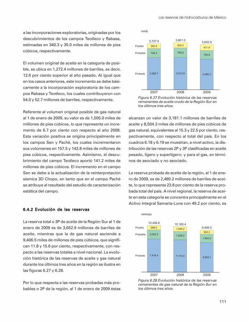
122 PEDESTRIAN AND STREETSCAPE GUIDE
evaluated 1,000 marked crosswalks atuncontrolled locations or locations with no trafficcontrol devices and 1,000 matched but unmarkedsites in 30 geographically dispersed cities in theUnited States. Detailed information collected foreach site included pedestrian crash history,pedestrian and traffic volumes, number of lanes,speed limit, type of median, type and conditionof crosswalk markings, and crosswalk location.Results of the study indicated that:
• Higher pedestrian volumes, higher average dailytraffic (ADT) rates, and a greater number ofroadway lanes are related to a higher incidenceof pedestrian crashes;
• Crosswalk location, speed limit, direction oftraffic flow, crosswalk condition, and crosswalk
Figure 78
Guidelines for the Installation of Marked Crosswalksat Uncontrolled Intersections and Mid-Block Crossings
Figure 79
Marked and UnmarkedCrosswalks at Intersection
Source: Safety Effects of Marked vs. Unmarked Crosswalks at Uncontrolled Locations , FHWA 2002

TOOLKIT 6–INTERSECTIONS 123
marking pattern were not related to theincidence of pedestrian crashes;
• Marked crossings had a higher incidence ofpedestrian crashes on multi-lane (4 or morelanes) roads with high ADTs;
• Marked and unmarked crossings had similarincidences of pedestrian crashes on all 2-, 3-,and multi-lane roads with lower ADTs;
• Pedestrians ages 65 and above were more likelyto be involved in crashes; and
• The installation of marked crossings did notalter motorist behavior (e.g., stop or yield topedestrians) or pedestrian behavior (e.g.,crossing without looking).
According to the research, on smaller roadwayswith lighter traffic volumes, markings do not
decrease the pedestrian crash risk; conversely, onlarge, high-volume roadways, the risk actuallyincreases. However, Zeeger, Stuart and Huang(1999) indicated that the higher risk observed onmulti-lane roadways with high ADT rates resultsfrom:
• An overall higher risk as the number of lanes orADT rate increases regardless of markings.
• Recognition that multi-lane roadways with highADT rates represent the most difficult scenariosfor pedestrian crossings, and
• The fact that marked crossings draw pedestriansto cross in that location, particularly in areaswhere the crossing is perceived to be difficult.
Zeeger, Stuart, and Huang emphasized that theneeds of pedestrians to safely cross streets cannotbe ignored and that engineering and roadwaytreatments should be used to minimize thepedestrian crash risk. Based on theserecommendations, it is rarely appropriate toremove crosswalk markings from multi-laneroadways with high average daily traffic. Instead,the markings should be enhanced withappropriate additional pedestrian treatments suchas signing, traffic calming, signalization, or othercountermeasures.
Crosswalk DimensionsThe MUTCD outlines requirements forminimum crosswalk widths and markings. TheMUTCD requires a minimum crosswalk width of6 feet. GDOT requires (and PROWACCrecommends) a minimum crosswalk width of 8feet. Wider crosswalks are often installed,particularly at crossings that receive high use. Awidth of 10 feet is commonly used for crosswalks.Crosswalks need to be at least the width of theapproaching sidewalk. (ITE Design and Safety ofPedestrian Facilities). The approaching sidewalk orwalkway and corner area at the intersection needsto be free of obstructions so that pedestrians canfreely travel in either direction to cross the street(see Figure 80).Typical marked crosswalk at intersection
124 PEDESTRIAN AND STREETSCAPE GUIDE
Crosswalk MarkingsCrosswalks can be marked using various methods.Crosswalk marking patterns vary and limitedinformation is available about the effectiveness ofdifferent designs. There is no evidence to supportthat one design is better than another, but somedesigns provide better visibility than others.Pedestrian visibility and safety can also beenhanced with advance stop or yield bars. Table45 lists guidelines for determining the need formarked crosswalks.
Generally, high visibility markings are suggestedfor locations where greater motorist warning isconsidered beneficial and where pedestrians maynot be expected to cross (such as mid-blocklocations), or where there are substantially higherpedestrian crossing volumes. Horizontal bars(two stripes perpendicular to vehicle traffic) aremost often used at stop controlled intersections.
Figure 80
Clear Travel Area for Pedestriansat Intersection Corners
Table 45
Guidelines for Determining the Need for Marked Crosswalks
• Pedestrian demand
• Sight distance
• Traffic volumes (daily and peak
hour)
• Vehicle gaps/vehicle speeds
• Characteristics of pedestrians
(school children, disabled people
using crosswalk)
• Existing and desirable lighting
levels
• Channelization refuge (island)
opportunity
• Destinations/origins in proximity
• Special concerns—school walking
routes, elderly needs, bus stops
• Collision history
• Distance to nearest crosswalk/
intersection
• Number of lanes to be crossed
• Opportunity to concentrate
pedestrian crossings at one
location
• Citizen support
• Mid-block versus intersection
• Compliance with adopted
standards (MUTCD) and other
guidelines
• Traffic Patterns and
Characteristics
• Driveway locations/number
• Other site specific or area-wide
considerations
How the above elements apply to crosswalk decisions varies depending on location.
Site specific engineering judgement/study should be conducted before implementation.

TOOLKIT 6–INTERSECTIONS 125
GDOT has adopted the ladder crosswalk design.Figure 81 shows GDOT’s crosswalk design andcrosswalk location detail. The GDOT crosswalkcombines the transverse striping of a basiccrosswalk with the higher-contrast piano keymarkings parallel to traffic flow. Properly sitedbetween the tire paths, the piano key markingsremain to mark the crosswalk even after thetransverse bars are badly worn. Piano keymarkings are also being used more frequentlybecause they provide the benefit of good visibilityand easier maintenance. With the piano keypattern (and the ladder bar), the wheels of motorvehicles typically pass on either side of themarkings, maximizing friction and minimizingdeterioration. Table 46 illustrates several styles ofcrosswalk markings and lists advantages anddisadvantages of each.
The minimum width of the horizontal barsrecommended by the MUTCD is 6 inches.GDOT’s minimum width for horizontal bars is 8inches. Wider bars, 10 to 12 inches, arerecommended by the ITE, particularly atcrosswalks that receive high use or deserve specialattention.
Stop bars are typically placed at intersectionswhere motorists are required to stop to preventoverhang into crosswalk areas. GDOT uses 24-inch stop bars, parallel to the crosswalk, thatextend across all approach lanes. Stop bars needto be located at least 4 feet in advance of thecrosswalk, and can either be parallel to the
crosswalk or angled or staggered in each lane toincrease visibility. Strategically locating andskewing stop bars improves visibility ofpedestrians, as well as operations for right-turn-on-red vehicles and for vehicles turning left fromthe cross street.
Advance stop and yield markings have beenshown to increase the visibility of pedestrians tomotorists by providing a wider range of visibilityon multiple lane roadways. When vehicles stoponly four feet from the crosswalk (the typicalstandard,) they tend to screen the view ofpedestrians from vehicles approaching in the otherlane(s). Buses and trucks in particular cause thisproblem, as do today’s larger sport utilityvehicles. As the potential for larger vehicles toapproach a crossing increases, the potential forpedestrians to be screened and blocked from theview of other vehicles increases. The underlyingprinciple behind advance stop lines is that theyincrease the safety of pedestrians by reducing thescreening effect of vehicles yielding to pedestrians.
One of the problems that can limit theapplication of advance stop lines is the reluctanceto use stop lines in what is a “yield” rather than a“stop” situation. Advance yield bars are arelatively new technology that are in the researchstage, and have the potential to mitigate theconcern about stop lines in yield situations. Also,
Advanced Yield Marking
GDOT recommended ladder crosswalk

126 PEDESTRIAN AND STREETSCAPE GUIDE
Figure 81
GDOT Crosswalk and Location Details
TOOLKIT 6–INTERSECTIONS 127
Marking Pattern
Horizontal Bars
Georgia
Department
of Transportation
Standard
Ladder Bar
Piano Key
Dashed (European)
Solid
Advantages
Common practice at stop
controlled intersections;
less expensive, easy to
install and maintain
Highly visible, horizontal
bar increases contrast for
pedestrians with visual
impairments; easy to
maintain
Highly visible
Highly visible and
becoming more commonly
used; easy to maintain
since stripes can be placed
outside the wheel friction
areas
Captures attention because
it is not a commonly used
pattern
Visible (but may not be as
eye catching as other
patterns); not commonly
used
Disadvantages
Not as visible as some other
marking types; bars tend to
wear faster than other types;
not appropriate for mid-block
locations
Wider stripes rub off with
wheel friction, but can be
placed to minimize this effect;
surface can be slippery
Wider stripes rub off with
wheel friction, but can be
placed to minimize this effect;
surface can be slippery
May not define space as well
as some of the other choices
Expensive; more difficult to
install and maintain; surface
can be slippery
Table 46
Advantages and Disadvantages of Crosswalk Marking Patterns
128 PEDESTRIAN AND STREETSCAPE GUIDE
because they are unusual and not frequently used,they are much more noticeable by motorists.Since they are currently in the experimental stage,permission for their use must be requested fromFHWA, and the proponent must agree torestoration of the location to comply withMUTCD if they prove to be ineffective.However, current research indicates that they areeffective in gaining compliance by motorists.
Advance yield markings should be located aminimum of 30 feet in advance of the markedpedestrian crossing, and should be used withcomplementary signing as shown in Figure 82.There is currently no standard for the “yield herefor pedestrians” sign.
Advanced stop markings should be monitoredregularly and maintained in good condition.They should also be removed when no longerneeded. Painted markings are less expensive thanplastic markings, but the plastic markers have alonger life. Check with your local agency forcrosswalk and pavement marking requirements.
Also, for more specific design details related topavement striping and marking techniques, referto other sources, such as the MUTCD.
Rumble strips with raised pavement markers orbuttons are sometimes placed in advance ofcrosswalks in rows, which create a “rumbling”effect, alerting approaching drivers to theupcoming crosswalk. Use of these types ofmarkers is not generally recommended unless theycan be placed far enough in advance of thecrosswalk to be an effective warning device (at thesame location as the crosswalk advance warningsign). Raised pavement markers should not beplaced near the right edge line because they are anobstacle to bicycle travel (see discussion in Toolkit5 — Sidewalks and Walkways). If raisedpavement markers are used, they should be placedoutside the required clearance area of bike lanes.The use of raised pavement markers should beanalyzed on a case-by-case basis. They shouldonly be installed after a traffic engineering studydetermines they are needed.
Curb RampsCurb ramps are often considered to be the mostimportant elements of an accessible pedestrianenvironment. Curb ramps provide accessibility atthe grade transition between intersection cornersand lower street grades. They facilitate crossingfor wheelchair users, people pushing strollers,bicyclists and others. If properly located, theycan also help to direct pedestrians, includingsight-impaired people, in the direction of thecrosswalk if they are properly located. Toolkit 2— Accessibility, discusses placement and designof curb ramps.
LightingThe street lighting level provided at intersectionsmay need to be supplemented with additionallighting in areas of heavy pedestrian traffic duringearly morning, late evening, or nighttime hours.Refer to the standards and design guidelines ofthe Illuminating Engineering Society of NorthAmerica.
Sign to Accompany Advance Yield Bar
Please note - This sign is experimental and not in MUTCD
Figure 82

TOOLKIT 6–INTERSECTIONS 129
Location of Drainage Inlets and GratesDrainage grates should be located away fromcrosswalks and curb ramps and outside the routeof pedestrian travel. It is preferable to locatedrainage inlets on the upstream side of thecrosswalk to avoid excessive drainage flows acrossthe crossing area. Roads and gutters should begraded to direct drainage away from intersectioncorners and walking areas.
Pedestrian Related SignsIt may be necessary to provide signs in advance of,at, or near an intersection. Regulatory signs aregenerally rectangular shaped signs that identifyspecial conditions and regulate motorists andpedestrians. Warning signs are diamond shapedwith black and yellow colors, and are used toidentify upcoming conditions that may not beexpected. Florescent yellow-green should be usedfor warning signs in school zones.
Pedestrian related warning signs include thestandard pedestrian crossing signs used atlocations to identify upcoming crossings (refer toFigure 83). The pedestrian warning sign with thepedestrian symbol should be used in advance ofcrossings in areas of high pedestrian use and atcrosswalk locations. Refer to MUTCD fordistance requirements for advance signing.
Minimizing the CrossingDistances at IntersectionsMinimizing the crossing distance at intersectionsenables pedestrians to cross the street more safely,efficiently and comfortably. Techniques thatreduce pedestrian crossing distance and time alsoprovide the added benefit of improved timing atsignalized intersections (without sacrificing theneed for an adequate protection phase for thepedestrian). Several design techniques forreducing crossing distances at intersections aredescribed in the following text.
Reduced Curb Return RadiusHistorically, design of curb return radii atintersections has not typically considered theneeds of pedestrians. With new design andretrofit design of intersections, it is important toconsider the needs of all users of the intersectionand to balance these needs to provide the safestoperating conditions for all.
The use of shorter curb return radii atintersections is beneficial for pedestrians becauseit reduces the crossing distance of the intersection.Reduced radii also help to slow vehicles as theytravel through the intersection, enabling drivers torespond more quickly to signal changes andcrossing pedestrians.
The need for shorter pedestrian crossing distancesand reduced vehicle speeds should be balancedwith the need to provide adequate curb radiuslengths to accommodate the types of vehicles thatcommonly turn at the intersection. A radius thatis too small can cause large vehicles and buses tojump the curb, causing deterioration of the curband intrusion into the waiting and standing spacefor pedestrians.
It may not always be practical to reduce the curbreturn radii at all intersections used bypedestrians, particularly at existing intersections.However, at intersections where there is heavypedestrian crossing activity and limited truck and
Crossing Sign
Source: Manual on UniformTraffic Control Devices
W11-2
Figure 83

130 PEDESTRIAN AND STREETSCAPE GUIDE
Table 47 summarizes the benefits and disadvantagesrelated to shortening curb radii at intersections.
Right-Turn Channelization (Slip) Lanewith Refuge IslandAt wide intersections, there is often a triangularspace between the through-lane and the right-turn lane (also called a “slip” lane) unused bymotor vehicles. Placing a raised island in this areaprovides pedestrians a refuge area when crossing.
bus turning movements it may be desirable toshorten the radius by adding curb extensions orbulb-outs. It may also be desirable to analyzetransportation routes in the area and to reroutetrucks onto streets that receive less pedestrian use.This would enable streets more heavily used bypedestrians to be retrofitted with shortened curbradii without significantly affecting the overalloperational needs of large trucks and buses in thearea.
If truck and bus turning activity occurs at aminimal level, AASHTO standards permit 15 to25 feet curb radii on minor streets, althoughshorter radii are allowed in certain situations. Onmajor streets, AASHTO allows a minimumturning radius of 30 feet if the occasional truckcan turn with some minimal encroachment.These standards may vary at the local level. Insome cases local jurisdictions may encourage theuse of shorter than standard curb radii atintersections where there is likely to be frequentpedestrian crossing activity, particularly in urbanareas. GDOT typically uses a radius of 30 feet inits designs.
Curb return radii larger than 30 feet generally arenot desirable where there are high numbers ofpedestrians crossing.
Figure 84 illustrates how reduced curb radius atan intersection shortens the pedestrian crossingdistance by comparing the crossing distancebetween two 15-foot radius corners with thecrossing distance between two 30-foot radiuscorners at an intersection.
In certain situations, very short curb radii of 5 feetcan be used on one-way streets at the cornerwhere no turning movements are possible. Figure85 illustrates how the use of one-way streetpatterns can enable reduced curb radii at the non-turning corners of the intersection. For morediscussion on one-way streets, refer to Toolkit 5— Sidewalks and Walkways.
Figure 84
Reduced Crossing DistanceWith Reduced Curb Radius
Figure 85
Reduced Curb Radii atOne-Way Intersection

TOOLKIT 6–INTERSECTIONS 131
Table 47
Benefits and Disadvantages ofShortening Curb Radii
Benefits
• Reduces crossing distances for pedestrians
• Slows vehicular movement through
intersection
• Heightens awareness of pedestrians
• Improves signal timing because the time for
the pedestrian crossing phase can be reduced
• Easier to install directional curb ramps
Disadvantages
• May not be feasible at intersections where
buses and large trucks turn frequently
• If radii are too small, larger vehicles may
either have to swing into opposing traffic or
drive over the curbing at the corner, causing
deterioration and intruding into pedestrian
waiting space
• May decrease vehicular capacity at intersection
This may be an appropriate solution where curbreturn radii of larger than 30 feet are unavoidable.This type of design is only appropriate for usewhen it fully addresses the needs of pedestrians.If designed properly, these devices can help tobalance the needs of large vehicles and pedestriansat busy intersections.
At locations with extremely high numbers of rightturning movements, slip lanes should beprotected with a signal to provide pedestriansopportunities to cross.
Also, refuge islands should be designed with anelongated tail (see Figure 86), which stretches outthe turning movement and provides vehicles morespace to slow and observe pedestrians crossing thelane. (This elongated design is recommended bythe Handbook for Walkable Communities as amethod to make right-turn slip lanes safer forpedestrians. It has not yet been incorporated intothe AASHTO Green Book.)
The refuge islands should be raised to provide avertical barrier and added protection betweenvehicles and pedestrians. Refuge islands need toprovide curb cuts, or cut-throughs if space islimited, for accessible passage. AASHTO requires
Figure 86
Source: Handbook for Walkable Communities, Burden and Wallwork
Elongated Refuge Island at Right-Turn Slip Lane

132 PEDESTRIAN AND STREETSCAPE GUIDE
that curbed islands generally be no smaller than54 square feet, but preferably a minimum of 100square feet. Triangular refuge islands should be aminimum of 20 to 25 feet long and not less than6 feet wide in the crossing region and 1.6 feetwide in the tail region. A wider area is needed toprovide curb ramps and a level area between thecurb ramps in the crossing region.
Pedestrian push buttons may be needed when thesignal timing doesn't allow all pedestrians to crossthe street on one crossing phase. These areasshould be clear of obstacles such as utilityfacilities and landscaping above 2 feet. Thecrossing point may be marked with a highlyvisible crosswalk design and a stop bar. Signingwith the message "STATE LAW - STOP FORPEDESTRIANS IN CROSSWALKS" is alsouseful to advise motorists that state law requiresthem to stop for pedestrians in crosswalks. Thesign should be placed near but in advance of thecrosswalk location. Directional barriers or devices(such as bollards, signs, landscaped strip, or otherelements) may be necessary to keep pedestriansfrom stepping off the curb in areas other than thecrosswalk.
Refer to Figure 87 for an example of a right-turnchannelization lane and refuge island at a largercurb radius intersection.
Medians and Center Refuge IslandsMedians and center refuge islands at intersectionsprovide waiting areas for pedestrians andeliminate the need for pedestrians to cross bothdirections of traffic all at once. Medians andcenter refuge islands can be created atintersections or mid-block to help define thepedestrian walking space and provide protectionand refuge from motor vehicles.
Refuge islands are typically shorter than medians,but either can be used at intersections. Mediansand center refuge islands provide the benefit ofturning one two-way street into two one-waystreets from the perspective of the pedestrian.Pedestrians only have to cross one direction oftraffic at a time and can wait and rest in betweenif necessary. Medians and refuge islands aregenerally most necessary where the length ofcrossing exceeds 60 feet, depending on the signaltiming, but can be used at intersections withshorter crossing distances where a need has beendetermined. Table 48 lists typical conditionswhere refuge islands can provide the greatestbenefit.
Table 48
Locations Where Refuge Islandsare Most Beneficial
• Wide, two-way streets (four lanes or more
with high traffic volumes, high travel
speeds, and large pedestrian volumes
• Wide streets where children, people with
disabilities, or elderly people cross regularly
• Wide two-way intersections with high traffic
volumes and significant numbers of crossing
pedestrians
• Lower volume or streets where there is
insufficient time to cross
• Minor access/local residential streets where
islands function both as traffic calming
devices and street crossing aids
“Stop for Pedestrians” sign

TOOLKIT 6–INTERSECTIONS 133
Medians and center refuge islands need to be largeenough to provide refuge for several pedestrianswaiting at once. They generally should be aminimum of 6 feet wide and preferably 8 feet wideor more where possible, face of curb to face of curb.These areas also need to be accessible, with eithercurb ramps or at-grade cuts. Cut-throughs aregenerally easier to construct and easier forpedestrians to negotiate than curb ramps,particularly on smaller islands.
Refuge islands should be raised to provide a verticalbarrier between pedestrians and motor vehicles.Sometimes a small nose can be placed in front ofthe crosswalk to provide additional protection topedestrians waiting at the median and refugeisland. The use of medians and refuge islands atintersections also help to provide added protectionduring left-turning movements. Pedestrian pushbuttons should be mounted in the islands toprovide pedestrians control over the signal phasesfrom their refuge position. Push button posts and
Right-Turn Slip Lane and Refuge Island
Figure 87
other poles need to be located out of thepedestrian travel way, but not inconveniently farfrom reach.
Figure 88 illustrates a median/refuge island at anintersection. For more discussion on medians andrefuge islands, refer to Toolkit 7 — Crossings.
Curb Bulb-Outs and ExtensionsIn addition to reducing crossing distances, curbbulb-outs and extensions make pedestrians morevisible to motorists at intersections. Curb bulb-outs and extensions at intersections and mid-block crossings may help to slow traffic bynarrowing the street. They should be consideredwhere on-street parking exists.
Curb extensions and bulb-outs work particularlywell on urban streets where there is limitedturning traffic by buses and large vehicles or thataccommodate one-way traffic, and on minorstreets in residential areas. They are also effective

134 PEDESTRIAN AND STREETSCAPE GUIDE
Typical Curb Extension Design
Figure 89
Median/Refuge Island at an Intersection
Figure 88
Figure 91
Curb Bulb-Outs and Extensions
Figure 90
Typical Curb Bulb-Out Design

TOOLKIT 6–INTERSECTIONS 135
in delineating on-street parking zones. Othertypes of traffic calming techniques are describedin Toolkit 8 — Traffic Calming. Figure 89illustrates a typical curb extension design, andFigure 90 illustrates curb bulb-outs. Figure 91illustrates how crossing distance is reducedthrough the use of curb extensions.
Avoiding or Reconfiguring Multipleand Skewed IntersectionsMultiple intersections are intersections with morethan four legs or vehicle approaches. Skewedintersections are created when intersections join atawkward angles, other than 90 degrees. Whendesigning new intersections or improving existingintersections, avoid creating situations where morethan four legs come together or where any of theintersection legs are skewed. Transportationagencies should consider reconfiguring skewedintersections. In Designing Sidewalks and Trailsfor Access, there are recommendations fordesigning skewed intersections.Recommendations include:
• Install curb ramps perpendicular to the curb
• Provide longer crossing times and accessiblepedestrian signals if the intersection is signalized
• Provide marked crosswalks
• Add medians to reduce crossing distances
• Consider installing intersection guidestripswhich provide directional information forpedestrians with vision impairments
Minimizing Pedestrian/MotorVehicle Conflicts
Corner VisibilityProviding good corner visibility at intersections iscommonly overlooked. Facilities such as signs,utility poles, bus stops, benches, and otherelements are often added after design andconstruction of an intersection, inhibiting driverand pedestrian visibility. These elements shouldnot be located in areas that interfere with sight
distances. Figure 92 illustrates the area at anintersection that typically should be kept clear ofobstructions. Refer to GDOT or local agencydesign standards for the adopted method tocalculate sight distance triangles at intersectionsand driveways.
Elements that obstruct the downward views ofhigh-seat position drivers (such as bus and truckdrivers) should also be avoided at intersections(within the corner visibility triangle area),including low branching trees, signs, hangingbanners, or other elements.
On-Street Parking RestrictionsOn-street parking near pedestrian crossing pointscan interfere with visibility. When cars are parkedtoo close to crossing points, they may block theline of sight between the driver and the pedestrianstepping off the curb to cross. This is a commoncause of pedestrian/vehicle collisions.
GDOT prefers parking spaces to be at least 20feet from crosswalks or stop signs. This is toassure that vehicles do not backup into acrosswalk when leaving a parking space (eitherparallel or angled parking). The ITE Design and
Figure 92
Visibility at Intersection Corners

136 PEDESTRIAN AND STREETSCAPE GUIDE
Safety of Pedestrian Facilities recommends thatparking be restricted within 50 feet of allintersection crossings where the speed of travel onthe street is 35 to 45 mph, and be restrictedwithin 100 feet at intersections on streets wherethe speed of travel is above 45 mph and at mid-block crossings (see Figure 93).
Designers should use professional judgement whenconsidering the appropriate distance for parkingsetbacks from specific pedestrian crossing points.
In certain situations, it may be appropriate torequire a greater setback distance (50 to 100 feet)from crossing points, such as:
• near schools where many children are crossing;
• at intersections or crossings that are notsignalized;
• on roadways where travel speeds exceed 35 mph;and
• on roadways with elements that affect sight andstopping distance (curves, bridges, vegetation,etc.)
In some situations, a setback less than 50 feet maybe appropriate, such as in central businessdistricts, downtowns, or other areas where travel
speeds are typically slower (between 20 and 30mph), and at signalized intersections or crossings.Curb extensions (bulb-outs) at intersections andcrossing points provide space for pedestrians tostand in better view of approaching vehicles, andon-street parking can be placed closer to thecrossing point without affecting visibility ofpedestrians.
Uncontrolled intersections and mid-blockcrossings are of particular concern whereinadequate sight distance exists, because there isno control (stop sign or signal) over themovements of vehicles and pedestrians.
Additional considerations related to on-streetparking are discussed in Toolkit 5 — Sidewalksand Walkways.
Traffic Regulation and AccessManagementTraffic regulation and access managementpractices can help reduce potential conflictsbetween pedestrians and motor vehicles atintersections. For more information about accessmanagement, refer to Toolkit 5 — Sidewalks andWalkways and Toolkit 10 — Site Design. Trafficcontrol and regulation devices are discussed inmore detail in the following text.
Figure 93
Recommended Parking Setback for Sight Distance

TOOLKIT 6–INTERSECTIONS 137
SignalizationThe needs of pedestrians should be considered atall traffic signal installations where pedestrianactivity might be expected.
Pedestrian Indications (Signal Heads andSymbols) and Exclusive Pedestrian PhasePedestrian signal indications include “WALK/DON’T WALK” or the symbolic man/handsymbol used in conjunction with traffic signals.The MUTCD provides a list of warrants forpedestrian indications. Traffic signal symbolsused to direct motorists may not provide thecorrect message to pedestrians. For this reason, itis strongly suggested that traffic engineers fullyconsider the need for pedestrian indications at allsignalized crossings that have the potential to beused by pedestrians.
Pedestrian indications are typically provided whenvehicular movement is controlled by actuatedequipment and when pedestrian actuators havebeen installed.
Pedestrian indications and signal heads need to beinstalled in clearly visible locations from thecrosswalk approaches. Audible devices are beingused in some areas. This type of indication isparticularly helpful to sight impaired pedestrians.For more information about audible devices, referto Toolkit 2 - Accessibility.
Research has documented that many pedestriansdo not understand the meaning of pedestriansignal indications, particularly the flashing“DON’T WALK” symbol.
Figure 94 illustrates the pedestrian indicationsymbols commonly used throughout the UnitedStates, as well as the action to be taken duringeach phase of the signal indication.
Where there is heavy pedestrian crossing activity(near a transit center or college campus, forexample), an exclusive pedestrian signal phaseshould be provided to allow pedestrians to cross
in one or more directions. A “pedestrianscramble,” where pedestrians are allowed to crossat all directions (including diagonal) within a welldefined intersection area is an example of anexclusive phase application. During this exclusivepedestrian phase, no vehicular movementtypically takes place.
Pedestrian Actuated SignalsPedestrian actuated signals may be warranted atintersections (and mid-block locations) wheregaps in the stream of traffic provide inadequateopportunities for pedestrians to cross. Installpedestrian actuated signals only where warrantedby the MUTCD, ADA guidelines, or engineeringjudgment. Adequate sight distance is necessary atthese locations, and warning signs should beinstalled in advance of the signal.
Some examples of locations where pedestrianactuated signals may be appropriate include:
Figure 94
Source: Manual on Uniform Traffic Control Devices
Pedestrian Indication Sequence
138 PEDESTRIAN AND STREETSCAPE GUIDE
• Intersection crossings where the level of pedestrianactivity may be relatively low, but the trafficvolume and speed of vehicles is high, or gaps intraffic are not adequate to allow pedestrians tocross
• Mid-block crossings on streets where pedestrianactivity is high and the volumes and speeds ofvehicular traffic are also high
• Heavily used crossings at mid-block bus stops(provide increased responsiveness of the actuationduring times of peak hour pedestrian access to thebus stop)
The MUTCD provides signal warrant guidelinesrelated to pedestrian actuated signals. Localjurisdictions may use other criteria to determine theneed for these signals. Toolkit 3 - Children andSchool Zones and Toolkit 7 - Crossings also discussthe use of pedestrian actuated signals. Also, refer toToolkit 2 - Accessibility for considerations relatedto placement and design of pedestrian actuationdevices for maximum accessibility.
Push Buttons (Actuators/Detectors)Pedestrian push buttons and detection devicesshould be conveniently located near the end ofcrosswalks and in easy to reach positions. Theyshould be located no more than 5 feet from thepedestrian travel way and face toward pedestrians.It is recommended that signs be mounted on thepush-button poles to identify which button to crossfor each crossing direction. The purpose and use ofpush buttons should be clearly identified, and theyshould clarify which crosswalk they are linked to.
In addition to being located at intersections,pedestrian actuators may also be located inintersection or mid-block refuge areas, wherepedestrians may be caught crossing during the endof the walk cycle. In some areas with heavypedestrian volumes, or where signal cycles areparticularly long, it may help to place additionalactuators in advance of the intersection to decreasepedestrian waiting time. Research shows that whenpedestrians have to wait on average over 30 seconds,
they have a tendency to not wait. Pedestrian useshould be considered when selecting cycle lengths.Table 49 lists recommended measures to improvethe effectiveness of push buttons.
The use of motion detectors, infrared, or videodevices to automatically change the signal phasewhen pedestrians approach the crossing is beingexperimented with around the country. Also,special signals are being tested that allow vehiclesto proceed in an intersection during the pedestriancycle when there are no pedestrians present.
Signal TimingSignals are often timed with a focus towardaccommodating smooth motor vehicle flows ratherthan accommodating the needs of pedestrians.Traffic signals are usually timed for vehicle speeds,causing pedestrians to have to stop at nearly everyintersection.
Signals with excessively long waits may causepedestrians to cross against the signal, increasingthe potential for pedestrian/motor vehicleconflicts. Research indicates that manypedestrians stop watching for the light to change,and instead start looking for gaps to cross streetswhen their delay exceeds 30 seconds. Installation
Table 49
Measures to Improve theEffectiveness of Push Buttons
• Maintain push buttons as necessary to
ensure they are functioning
• Make push buttons responsive to
pedestrians
• Provide signing to show which street
crossing the push button controls
• Sign operating times for push buttons
designed to operate only during certain
times

TOOLKIT 6–INTERSECTIONS 139
of pedestrian actuation devices can help with thisproblem.
Signals that do not provide enough time forpedestrians to cross are also a major concern. Thewalking speed normally used by GDOT forcalculating pedestrian walking time is 4 feet persecond, but this may not provide adequatecrossing time for all pedestrians. GDOT willconsider varying from the standards under certaincircumstances. Pedestrians sometimes travel atslower speeds and thus may need more crossingtime.
Studies have indicated that up to 30 percent ofthe population do not normally walk as quickly as4 feet per second. Recent research by Knoblauch,Pietrucha, and Nitzburg determined that fordesign purposes, values of 3 feet per second areappropriate for older pedestrians. Other studieshave indicated that some pedestrians withmobility impairments travel at 2.5 feet per secondor slower. Table 50 depicts the length of time
necessary to cross various distances at thesespeeds. This table is provided to compare thedifferences in crossing time that can occur withdifferent pedestrian groups. Set or adjust signaltiming to accommodate a greater cross-section ofthe population. Several sources, including theITE manual Design and Safety of PedestrianFacilities, are recommending the use of the 3 feetper second travel speed for signal timing.PROWAAC recommends a walking speed of 3.5feet per second be used for calculation of crossingtime.
MUTCD recommends using a walking speed of 4feet per second, but GDOT recommends using3.5 feet per second when there is a knownpresence of slower pedestrians (including elderlyand people with mobility impairments) whoregularly use a crossing (near a retirement homeor hospital). The possibility of extending signalcrossing time in these areas should be considered.
Crossing Distances, Speeds, and Time
Average Pedestrian Older Adult Mobility Impaired Pedestrian
Crossing Crossing Time at Crossing Time at Crossing Time at
Distance 4 ft/second 3 ft/second 2.5 ft/second
24 ft—2 lanes 6 seconds 8 seconds 9.6 seconds
34 ft—2 lanes* 8.5 seconds 11.3 seconds 13.6 seconds
with bike lanes
46 ft—3 lanes 11.5 seconds 15.3 seconds 18.4 seconds
with bike lanes
58 ft—4 lanes 14.4 seconds 19.3 seconds 23.2 seconds
with bike lanes
70 ft—5 lanes 17.5 seconds 23.3 seconds 28 seconds
with bike lanes
* Assumes 12-foot vehicular lane width and 5-foot bike lane width.Source: Adapted from walking speed estimates
Table 50

140 PEDESTRIAN AND STREETSCAPE GUIDE
WALK Signal TimingAt some intersections, the 4 to 7 second “start-up”time walk interval recommended by the MUTCDmay present a dilemma to pedestrians who see the“DON’T WALK” display before they are morethan one or two lanes across the street, especiallysince as discussed earlier, many pedestrians do notalways understand that the flashing “DON’TWALK” symbol doesn’t mean to stop walking. Itmay be desirable to provide a longer “WALK”interval at some locations, like at particularly wideintersections, or in areas where there is clearlyconfusion among crossing pedestrians.
A device currently being used in several citiesaround the country, the Countdown Signal,displays the number of seconds left for thepedestrian to cross the intersection.
Turning MovementsRegulating turning movements at intersections canimprove conditions for pedestrians. According tothe ITE, 37 percent of all pedestrian/motor vehiclecollisions at signalized intersections involve left- orright-turning vehicles. Table 51 lists potentialsolutions to minimize pedestrian/motor vehicleconflicts involving left- or right-turning vehicles.
Right turn channelization should not be usedwithout consideration of pedestrians. The additionof a right-turn lane increases crossing distances forpedestrians and allows vehicles to travel more freelywhen turning right through the intersection. Thismay cause inattentive drivers to not noticepedestrians on the right. Elimination of free-right-turn-on-red movements may be an appropriatesolution at certain intersections where there is ahigh level of anticipated conflict with motorvehicles.
Dual Right Turning MovementsIt is strongly recommended that dual right turningmovements be avoided at intersections used bypedestrians. Criteria for dual turn lanes should bedeveloped and used to ensure that they areprovided only when necessary. If dual turn lanes
are installed, a separate pedestrian crossing phasein a signal should be provided.
Dual right turning movement lanes areparticularly difficult for pedestrians. Dual rightturn lanes increase the level of unpredictablemovements at intersections. Visibility is impairedwhen multiple vehicles are turning at the sametime. In addition, dual turning lanes may not bewell utilized by motor vehicles. One lane may befavored and as a result, motor vehicle speeds maybe different in each lane. Drivers are often notable to see beyond the car in front or to the side
Table 51
Suggestions for ReducingTurning Conflicts
• Design compact intersections with small
turning radii that force slower speeds
• Prohibit right-turn-on-red
• When right-turn slip-lanes are used, place
crosswalks as far upstream (with respect to
traffic flow) as possible and provide highly
visible markings
• Restrict left turns at downtown intersections
and on commercial streets, during certain
hours when there are higher concentrations
of pedestrians at intersections, or provide
left turn arrows for motorists before
allowing pedestrians to use crosswalk
• Shorten crossing distance and exposure
time with curb extensions or bulb-outs
• Provide medians and refuge islands
• Place signs to remind motorists of their
duty to yield to pedestrians while turning
left or right
• Provide well-illuminated crossings
• Improve marking and visibility of crosswalks
Sources: ITE Design and Safety of Pedestrian Facilities,

TOOLKIT 6–INTERSECTIONS 141
of them to determine if there is a pedestriancrossing the street, a common cause of pedestriansbeing hit at intersections.
For right-turn channelization lanes, consider thepossibility of adding a controlled slip lane with arefuge island, which provides added protection forcrossing pedestrians if designed properly (seediscussion earlier in this section). This solutionshould only be used where right turnchannelization is necessary or already exists.
Interchanges and Expressway RampsExpressways and freeways often present barriers topedestrian circulation. Pedestrians crossing exitand entrance ramps often conflict with driversaccustomed to traveling at high speeds. Drivers'attention is often focused on other traffic and noton pedestrians.
Several design treatments can be applied toimprove pedestrian crossing at interchanges.
• Provide as short a crossing distance as possibleand at a right angle to the ramp.
• The crossing point should be located at eitherthe terminus or the beginning of the ramp,where the vehicle is just entering or has slowedfrom its exit.
• Entrance and exit ramps that encourage free-flowing motor vehicle movements are achallenging area for pedestrian crossings (such ascloverleaf ramps and single point urbaninterchanges). Special elements should beconsidered to warn both drivers and pedestriansof potential conflicts, such as in-pavementflashers, more extensive signing, and flashingbeacons when pedestrians are present.
• Interchanges and access ramps connecting tolocal streets at right angles are easiest forpedestrians to cross, because crossing distancesare reduced and visibility is enhanced. Theseintersections should be designed in accordancewith accepted practices. Controls such as stop
signs and signals provide pedestriansopportunities to cross.
• With ramps that merge into the local streetsystem at expressway access points,channelization islands can be installed toprovide refuge area for crossing pedestrians.This reduces crossing distance for pedestrians,which helps to improve signal timing. Theshorter the ramp crossing distance, the better.
• Pedestrian crossings at controlled access rampsneed to be clearly marked and identifiable toapproaching motorists.
• Good sight distance and visibility at rampterminals is an important necessity.
• Grade separation may be necessary (seediscussion later in this section).
Grade SeparationGrade separation may be necessary at crossingswhere extreme conditions dictate the need forpedestrians to be completely separated from theroadway (or from railroad tracks or waterways). Ifdesigned properly, overpasses and tunnels canprovide safe pedestrian crossing opportunities.However, they can also be extremely costly andmay make it difficult to provide accessibility,unless there is sufficient space for ramping (if not,elevators are necessary). In some cases, if theadded travel distances are excessive, pedestrianswho want the most direct route may bediscouraged from using the grade separatedcrossing. The use and placement of gradeseparated crossings should be carefully considered.Criteria for determining the need for gradeseparation and additional design information isprovided in Toolkit 7 — Crossings.
Traffic Circles — Roundabouts versusTraffic Calming CirclesVarious types of traffic circle designs exist aroundthe world. Traffic circles provide differentsolutions for different traffic needs and somedesigns are more beneficial for pedestrians thanothers. There are two types of traffic circles

142 PEDESTRIAN AND STREETSCAPE GUIDE
commonly used — roundabouts and trafficcalming circles. Roundabouts typically increasethe volume of traffic traveling throughintersections. Traffic calming circles decreasetraffic speeds and are most appropriate on lowvolume streets.
Roundabouts are used at intersections in place ofsignals and carry significant traffic volumes. Theirprimary purpose is to provide motor vehicles freeflowing mobility at a lower speed. Figure 95illustrates an example of a modern roundaboutdesign.
Traffic calming circles are used at low volumeneighborhood intersections for speed control andto discourage through trips. Figure 96 illustratesan example of a traffic calming circle.
For these reasons, roundabouts typically createless favorable conditions for pedestrians thantraffic calming circles. Characteristics related toroundabouts and traffic calming circles and theireffect on pedestrian travel are summarized below.Additional information about traffic calmingcircles and other traffic calming devices isprovided in Toolkit 8 — Traffic Calming.
Modern Roundabout Design
Figure 95

TOOLKIT 6–INTERSECTIONS 143
RoundaboutsModern roundabouts are designed to slow traffic,reduce delays, and handle higher traffic volumes.Research has shown fewer pedestrian collisionsoccur at modern roundabouts than at signalizedor unsignalized intersections. If properlydesigned, modern roundabouts can create apositive environment for pedestrians.
Roundabouts allow pedestrians to crossfrequently, without waiting for traffic to stop(when vehicular volumes are low to moderate).However, pedestrians crossing are not protectedsince vehicles are free flowing. Pedestriansidentify and accept gaps in traffic and cross whenit is safe.
Splitter islands are used to deflect the path ofmotor vehicles and to slow them as they approachthe roundabout. This deflection reduces vehiclespeeds, making it easier for pedestrians to crossthe path of a vehicle entering the roundabout.Splitter islands also provide crossing refuge forpedestrians. Locate pedestrian crossings about 20feet from the yield line. This allows pedestrians
to cross behind the first motor vehicle trying toenter the roundabout.
Consider providing priority crossings wherepedestrian volumes are high, or where there aremany young, elderly, or disabled citizens wantingto cross or where pedestrian delays are long. Placethese crossings at least 75 feet downstream of theexit. PROWAAC recommend providingpedestrian signals at pedestrian crossings,particularly to aid crossing of pedestrians withvisual impairments. This is a significant measureand would only be considered where the designerhad significant concerns about crossing safety forusers. Placing the pedestrian crossing furtherfrom the larger roundabouts helps to reducebackup of traffic into the roundabout when trafficis stopped.
Traffic Calming CirclesTraffic calming circles are very effective inreducing vehicle speeds and discouraging non-local trips through neighborhoods, which benefitspedestrians. Traffic calming circles also create acondition where vehicles are forced to stop orsignificantly reduce their speed at theintersection, which allows better opportunities forpedestrians to cross.
A drawback of some traffic calming circle designsis that vehicles need to swing wide at theintersection to avoid the center barrier andvehicles may intrude into the pedestrian crossingarea if insufficient space is provided for theturning movement. A minimum of 13 feet ofclearance between the circle edge and the crossinglocation is recommended when designing trafficcircles. Another drawback is that some drivers tryto take the shortest path through the trafficcalming circle and turn toward the left, ratherthan going all the way around the circle. Thiscreates an unexpected movement for crossingpedestrians.
Figure 96
Traffic Calming Circle

144 PEDESTRIAN AND STREETSCAPE GUIDE
Raised IntersectionsIn some cases, raised intersections may be asuitable solution, but this practice is stillconsidered experimental in most areas. Raisedintersections create an area that clearly functionsfor primary use by pedestrians. Approachingmotorists can see that the intersection is not alocation designed for rapid, through-movement,which causes them to slow down and yield theright-of-way to pedestrians. Raised intersectionsare not appropriate for high-speed thoroughfaresand major arterials and collectors. Localrequirements may prohibit their use under avariety of circumstances. Raised intersections maybe most appropriate in urban centers anddowntowns where traffic is already moving slowlythrough intersections.
Raised intersections make it easier to meet theADA requirements because the crosswalk is anatural extension of the sidewalk, with no changein grade. Raised intersections require specialtreatment, such as tactile warning strips oraudible signals, to make them detectable to thevisually-impaired.
Placement of drainage inlets is simplified at raisedintersections, because surface water will drainaway from the center of the intersection.
Special PavingSpecial paving techniques are sometimes used tomark crossings at intersections in urban areas,particularly in special districts. Changes inpavement color and texture raise a motorist’sawareness through increased visibility, noise, andvibration (see Figure 97).
Crossings constructed with special paving shoulduse nonslip bricks or unit pavers. Scored orstamped colored concrete surfaces can also beused, and are generally more durable over thelong term than unit pavers, with more uniformjoints and less chance of displacement. However,creation of a reduced vibration zone within thecrossing area is recommended (PROWAACX02.1.1). Refer to Toolkit 2 - Accessibility.Special paving surfaces should be installed andmaintained in a smooth, level, and cleancondition. Care should be taken to ensure thatgrooves and joints do not impact accessibility.
Because the color contrast between special pavingfeatures in crosswalk and adjacent pavementdiminishes over time, horizontal crosswalkmarkings should be used.
For state routes and GDOT and TE fundedprojects, the use of brick pavers is not allowed.The use of stamped concrete and/or stampedasphalt is acceptable when the followingconditions are met:
Colored and textured paving in a crosswalk
Figure 97
Special Paving

TOOLKIT 6–INTERSECTIONS 145
• The crossing is at a 90 degree angle with nocurves to the roadway;
• The width of the treatment is less than 10 feet;
• Current ADT is 5,000 or less and truck volumeis 10% or less; and
• When asphalt treatment is used; themaintenance agreements include the statementthat when DOT resurfaces the roadway, theresurfaced treatment will be asphalt only, unlessthe sponsor funds architectural treatment.
GDOT’s Chief Engineer reserves the right towaive any of the above requirements if needed andwarranted.
Research is ongoing and design professionals andtraffic engineers should investigate the benefitsand disadvantages of the latest techniques andapproaches when seeking to implement innovativetreatments at intersections.
Other Sources of Information
The following sources of information arerecommended for design of intersections. Please seethe Resource Guide included at the end of thisguide for complete bibliography information.
A Policy on Geometric Design of Highways andStreets, 1994, American Association of StateHighway and Transportation Officials
An Analysis of Pedestrian Conflicts with Left-TurningTraffic, Dominique Lord
Flashing Beacons, Association of Washington Citiesand the County Road Administration Board
Curb Ramps for Accessible Pathways, Bureau ofTransportation Engineering and Development,Office of Transportation, City of Portland
Design and Safety of Pedestrian Facilities, A ProposedRecommended Practice of the Institute of
Transportation Engineers, ITE Technical CouncilCommittee 5A-5
Design Manual, Washington State Department ofTransportation
Field Studies of Pedestrian Walking Speed and Start-Up Time, Richard L. Knoblauch, Martin T.Pietrucha, and Marsha Nitzburg
Florida Pedestrian Planning and Design Guidelines,University of North Carolina
Guidelines for the Installation of CrosswalkMarkings, Steven A. Smith and Richard L.Knoblauch
Handbook for Walkable Communities, WashingtonState Pedestrian Facilities Planning and DesignCourses, Dan Burden and Michael Wallwork, PE
Manual on Uniform Traffic Control Devices forStreets and Highways, 1988 Edition, USDepartment of Transportation
Oregon Bicycle and Pedestrian Plan, An Element ofthe Oregon Transportation Plan, OregonDepartment of Transportation Bicycle andPedestrian Program
“Pedestrian Actuated Crosswalk FlashingBeacons,” John W. VanWinkle
Pedestrian Crossing Study, Final Submittal,Pedestrian Traffic Control Measures, Arctic SlopeConsulting Group, Inc.
Pedestrian Improvements Demonstration Project,Kirkland Avenue at Main Street, Kirkland Avenueat Third Street, Lake Street South, Specifications andContract Documents, KPG, Inc.
Pedestrian Signal Installation Policy, David I.Hamlin and Associates

TOOLKIT
CROSSINGS
147
7
This Toolkit SectionAddresses:
• Determining the Need for Mid-Block Crossings
• Mid-Block Crossing Design
• Railroad Crossings
• Grade Separated Crossings
• Multi-Use Trail Intersections and Crossings
• Boardwalks and Trestles
• Other Sources of Information
This section discusses the need for and describesdifferent types of mid-block crossing treatments,including marked crosswalks, mid-block actuatedsignals, median refuge islands, overhead signs, andflashing beacons. Standard practices, as well assome new techniques being tried around thecountry and in Canada, are discussed. Othertypes of non-street intersection crossings, such asrailroad crossings, grade-separated crossings,multi-use trail and pathway crossings, and bridgesare also addressed. Crossing design treatments forstreet intersections are covered in Toolkit 6 -Intersections.
In all cases, the crossing treatment design appliedto a specific location should be guided by a trafficengineering study of the existing conditions andintended function of the crossing.
Mid-block crossing with median refuge island.
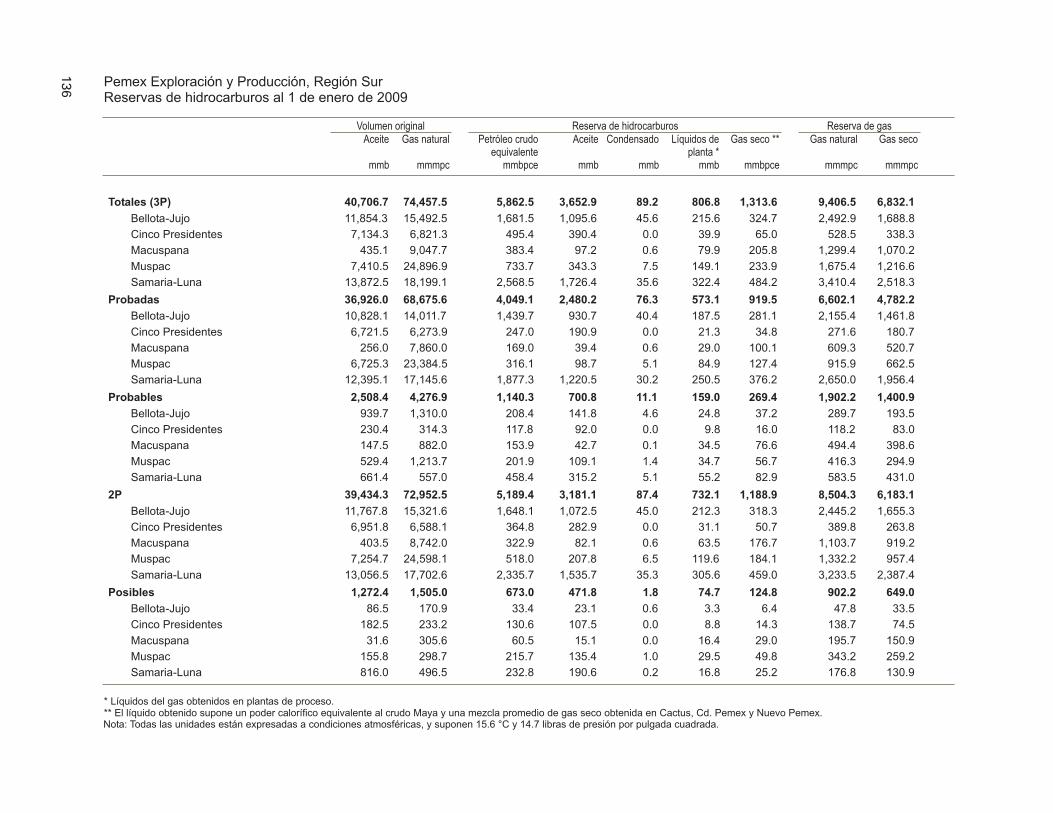
148 PEDESTRIAN AND STREETSCAPE GUIDE
Determining the Need forMid-Block CrossingsIn some urban areas where distances betweenintersections are long, mid-block crossing pointsprovide pedestrians opportunities to cross safely.Mid-block crossings can also provide convenienceand safety in less developed areas, wherepedestrian activity is high (such as between anapartment site and a grocery store; a school and apark; or a transit stop and a residentialneighborhood). Figure 98 illustrates a typicalmid-block crossing.
Locations being considered for a mid-block crossingneed to be carefully studied. The followingguidance for determining locations for mid-blockcrossing installation is provided by the ITE manual,Design and Safety of Pedestrian Facilities:
• Where significant pedestrian crossings andsubstantial pedestrian/vehicle conflicts exist;(should not be used indiscriminately)
• Where the crossing can serve to concentrate orchannelize multiple pedestrian crossings to asingle location;
• At approved school crossings or crossings onrecommended safe school walk routes;
• Where land uses create high concentrations ofpedestrians needing to cross (such as residentialareas across from retail or recreation, and transitstops across from residential or employment);
• Where pedestrians could not otherwiserecognize the proper place to cross or there is aneed to delineate the optimal location to cross;
• Where there is adequate sight distance for themotorist and pedestrian. (Any obstacles thatwould interfere with visibility at the crossinglocation such as mailboxes, utility poles, streetfurniture, and landscaping should be removedor relocated. On-street parking should be setback from the crossing point for improvedvisibility. Refer to Toolkit 6 - Intersections forrecommended parking set back distances); and
• Installed on the basis of an engineering study iflocated at other than an existing stop sign ortraffic signal.
Smith and Knoblauch developed criteria relatingto pedestrian and vehicle volumes for determining
Figure 98
Typical Mid-Block Crossing

149TOOLKIT 7–CROSSINGS
where marked crossings should be located. Referto Toolkit 6 - Intersections, which provides achart illustrating this criteria. This chart alsotakes into account street widths and other factors(such as concentrations of children, older adults,and pedestrians with mobility impairments).
Mid-block crosswalks should generally be avoidedunder the following circumstances (unless theyare stop controlled):
• Immediately downstream (less than 300 feet)from a traffic signal or bus stop where motoristsare not expecting pedestrians to cross;
• Within 600 feet of another crossing point(Knoblauch et. al.), except in central businessdistricts or other locations where there is a welldefined need. The recommended minimumseparation in most cases is 300 feet; and
• On high speed streets with speed limits above45 mph.
Refer to Toolkit 6 - Intersections for designguidelines related to crosswalks, including somelocal agency approaches to crosswalk installation.
Mid-Block Crossing DesignCrossing design treatments are often used incombination with one another at mid-blockcrossings. Standard practices, as well as somemore innovative techniques being tested around
the country, are described. Determining methodsof crossing design treatments and related trafficcontrol requires careful consideration and trafficengineering analysis of existing conditions on aproject by project basis.
Marked CrosswalksIt is strongly recommended that all mid-blockcrossings be marked with highly visiblecrosswalks, otherwise pedestrians and motoristsmay have trouble recognizing the designatedcrossing point. Mid-block crossings shouldalways include marked crosswalks, but mid-blockcrossings should only be located where a specificneed has been determined.
It should be noted that marked crosswalks aremeant to clarify the right-of-way and guidepedestrians to cross at the safest location. Theyare not safety devices to protect pedestrians fromvehicles. There have been studies that haveshown that marked crosswalks may instill a falsesense of security in pedestrians (see discussion inToolkit 6 - Intersections). There are also concernsthat when crosswalks are installedindiscriminately or too frequently, they mayeventually become less obvious to motorists. Forthese reasons, it is important to fully consider theneed for mid-block crossings before installation.
Various crosswalk designs are discussed in Toolkit6 - Intersections. The use of ladder or piano barmarkings are highly recommended over the use ofother types of crosswalk markings because of theirhigh visibility. Horizontal bars are not typicallyused at locations other than controlledintersections. Crosswalk markings should be at90 degrees to the street to identify the shortestpath for crossing and minimize pedestrianexposure. In refuge islands, angling the crossingprovides an opportunity for pedestrians to viewoncoming traffic.
Stop lines or bars should be placed in advance ofcrosswalks. These are usually 12 to 24 incheswide solid white lines that extend across all
Midblock crossing in Helen, GA

150 PEDESTRIAN AND STREETSCAPE GUIDE
approaching lanes. They are usually installed at aminimum of 4 feet in advance of the crosswalk toprevent motorists from encroaching into thepedestrian crossing space. Some jurisdictionsinstall stop lines further in advance of crosswalksat mid-block locations to provide improvedvisibility and buffer distance between the motorvehicle and the crosswalk.
Raised pavement markers placed in rows are oftenused in advance of mid-block crosswalks. If used,they need to be placed far enough in advance ofthe crosswalk for the rumble effect to provideadequate warning to the motorist. They shouldbe placed in combination with and at the samedistance as pedestrian advance warning signs toenhance motorist awareness. Because raisedbuttons and pavement markers can be a hindranceto bicycle travel, they should not be placedadjacent to the right edge line or within bikelanes. A minimum clearance of 2 feet isrecommended between such markers and anybicycle travel area. Raised pavement markers aredifficult to maintain in areas of snow removal.
A mid-block crossing of a two-lane arterial isillustrated in Figure 99. Various types of devicesthat can be used in conjunction with crosswalks atmid-block locations are discussed below.
Mid-Block Pedestrian Actuated SignalsThe MUTCD bases the need for pedestriancrossing traffic control on the number of adequategaps or space between the vehicles in theroadway’s traffic stream. It states that pedestriansmust wait for a gap in traffic that is of sufficientduration to permit street crossings withoutinterference from vehicular traffic. When thedelay between adequate gaps or spaces becomesexcessive, pedestrians may become impatient andendanger themselves by attempting to cross thestreet during inadequate gaps.
When adequate gaps occur less frequently than anaverage of once per minute, some form of trafficcontrol is necessary. Pedestrian actuated signals
or grade separated facilities should be consideredas possible solutions for roadways with thesecharacteristics.
Pedestrian actuated signals are often appropriatefor roadways that have high traffic volumes orspeeds, or four or more lanes. Since these signalsonly operate in the presence of foot traffic, theydo not cause undue delay to vehicles duringperiods of low pedestrian volumes.
Pedestrian actuated signals should be consideredin locations where pedestrian walk routes crossmajor arterials or other high volume or high speedfacilities. A signal warrant analysis should beperformed to study specific conditions anddetermine if a pedestrian actuated signal shouldbe installed.
Medians and Refuge IslandsMedians and refuge islands are raised longitudinalspaces separating the two main directions of trafficmovement in the street. Refuge islands areshorter than medians, typically up to 20 feetlong, compared to over 100 feet long. Refugeislands are more commonly used at mid-blockcrossings than medians, but either provides majorbenefits for pedestrians and motorists.
Mid-block crossing. Notice how median path directspedestrians to look at oncoming traffic.

151TOOLKIT 7–CROSSINGS
Figure 99
Mid-Block Crossing of Two-Lane Arterial
Medians and refuge islands reduce crossingdistances for pedestrians and effectively turn onetwo-way street into two one-way streets forpedestrians. Pedestrians only have to cross onedirection of traffic at a time and can wait or rest inbetween. This creates a better opportunity forpedestrians to find gaps in the flow of trafficbefore crossing the street. Medians and refugeislands are a benefit to drivers when located atmid-block crossings, because they help to better
identify the upcoming crossing point. They alsoprovide a location for a pedestrian crossing sign inthe middle of the street, providing anotheropportunity to warn drivers of the crossing.
Medians or refuge islands are recommendedwhenever crossing distances exceed 60 feet toprovide a waiting and resting area for slowerpedestrians. Medians and refuge islands also canbe designed to block side street or driveway

152 PEDESTRIAN AND STREETSCAPE GUIDE
Refuge Island
crossings of the main road and block left-turningmovements. Because medians reduce turningmovements, they have the ability to increase theflow rate and safety of the roadway.
Refuge islands can be installed with moreflexibility in a variety of locations because they areshorter. Refuge islands are easily located on lowvolume, low speed roadways, such as 25 to 30mph collectors or subcollectors throughneighborhoods. When collectors are longer andhandle more traffic and higher speeds, medians orrefuge islands are helpful. On multi-lane minorand major arterials, raised medians or refugeislands are essential.
Figure 100 illustrates a mid-block crossingdesign. Table 52 lists several design guidelinesfor medians and refuge islands.
Raised Mid-Block CrossingsRaised mid-block crossings are sometimesconstructed to provide a well-defined pedestriancrossing as well as traffic calming. This type ofcrossing is only suitable for low speed, low volumelocal streets, since the raised crossing is essentiallyfunctioning as a speed table or hump.
Raised crossings enhance pedestrian safety bycreating a vertical pavement undulation thatforces motorists to slow down when approaching.Raised crossings function as an extension of thesidewalk and allow pedestrians to cross at a
constant grade, without the need for curb rampsor median cut-throughs. For detection bypedestrians who are blind, truncated domedetectable warnings should be installed at theedge of the street and the median.
Raised crossings should have a 6-foot parabolicapproach transition, raising the vehicle 3 to 4inches above the nominal pavement grade. Theflat section of the crossing table should be 10 to12 feet wide. The need for additional catchbasins to handle interrupted gutter flow shouldbe considered.
Raised crossings need to be highly visible, eitherstriped as a mid-block crossing or constructed of acontrasting pavement design (such as unit paversand stamped or colored concrete). The pavementsurface must be smooth and stable, without deepgrooves or joints to provide maximum accessibility.A detectable surface should be used to distinguishthe end of the sidewalk and the beginning of theroadway to assist visually impaired persons.
Raised crossings should be signed with advancewarning signs and pedestrian crossing signs in thesame manner as other mid-block crossings. Referto Toolkit 8 — Traffic Calming for morediscussion on traffic calming techniques.
Raised mid-block crossing — note high visiblepavement surface

153TOOLKIT 7–CROSSINGS
Figure 100
Mid-Block Crossing of Five-Lane Arterial with Existing Median

154 PEDESTRIAN AND STREETSCAPE GUIDE
Flashing BeaconsThe use of flashing beacons is controversial,because if they are used indiscriminately, theyeventually become “invisible” to motorists (seemore discussion in Toolkit 3 - Children andSchool Zones). A crosswalk with a flashingbeacon provides a relatively low cost treatment formid-block pedestrian crossings. These devices areauthorized by the MUTCD, under the sectionsrelated to hazard identification beacons. Theflashing light alerts drivers in advance of potentialpedestrians without forcing them to stop, unlessthere is actually a pedestrian in the crosswalk.This sort of device can be used on roadways withhigher vehicular volumes without causing anyundue delay to drivers.
Flashing beacons are most effective if they areoperating only during times when there is a clearneed to alert the motorist, like when pedestriansare actually present (rather than constantlyflashing all the time). Some communities aroundthe country are experimenting with differenttypes of pedestrian actuated flashing beacons.
A pedestrian-actuated flashing beacon has beenused successfully for a number of years inChattanooga, Tennessee (ITE Journal, January1997). The typical design consists of overheadsigns with the message “Yield to Pedestrians —25 MPH When Flashing” with dual 8-inchbeacons mounted approximately 300 feet inadvance of the crosswalk in both directions. Pushbuttons are mounted on pedestal poles on both
Table 52
• Medians and refuge islands should be a
desirable width of 8 to 10 feet wide and a
minimum width of 6 feet wide to prevent
wheelchair users, bicyclists, and people with
strollers from projecting out into the stream of
motor vehicle traffic. In some cases, smaller
width medians and refuge islands may be
acceptable, particularly when there is limited
space in the right-of-way, depending on local
requirements and existing conditions (check
with your local agency).
• In order to obtain appropriate median width,
travel lanes can be narrowed to 11 feet, if
allowed by local standards. In locations where
vehicle speeds range from 20 to 30 mph, the
travel lanes can be reduced further to 10 feet,
if allowed by local standards.
• Trees in medians and at the sides of streets
can help to narrow the long range field of
vision for approaching drivers, causing them to
slow down as they near the crossing point.
Landscaping in median refuge islands must be
handled carefully. It is essential that
landscaping not block the sight lines of
pedestrians and motorists at the crossing area.
Design Guidelines for Medians and Refuge Islands
Placement of trees must comply with
applicable clear zone requirements.
• Curb ramps or full cut-throughs should be
installed in all median refuge islands. Cut-
throughs are more common because the
median width is sometimes not large enough
to accommodate ramps that meet the ADA
requirements. Cut-throughs should be
designed with a maximum 2 percent cross
slope to allow water, silt, and debris to drain
from the area.
• A pedestrian push button should be placed in
the median of signalized mid-block crossings
where the crossing distance exceeds 60 feet.
• The use of angled (45 degrees+) refuge areas in
the island should be considered (see figures later
in this section). These provide the benefit of
directing and encouraging pedestrians to look in
the direction of oncoming traffic, helping
them to be more aware of approaching
vehicles. Pedestrians are also prevented from
darting directly out into traffic. See Figure 83.
• Medians and refuge islands should be illuminated.

155TOOLKIT 7–CROSSINGS
Overhead flashing beacon
sides of the crosswalk, along with auxiliary flashersthat confirm to the pedestrian that the overheadbeacons have been activated. Signs are also postedinstructing the pedestrian in the use of theflashers. Once activated, the beacons arecontrolled by a timer housed in the flashercabinet.
Soft SandwichThis technique is being used at the Georgia StateCapitol campus, in New Jersey and other areasand involves the use of heavy plastic “sandwichboard” signs cautioning motorists to yield topedestrians. These signs are typically placed inthe center of the roadway (see Figure 101).
Earlier “hard” versions of these signs were bannedby the New Jersey DOT because they couldbecome projectile objects when hit by a vehicle.Some towns are now testing flexible or “soft”versions of these signs that will not injurepedestrians or cars when hit.
In–Roadway Warning LightsAn effective warning system that alerts motoriststhat a pedestrian is crossing or waiting to cross thestreet are at grade or in-roadway flashing warninglights. Originally developed from airportpavement warning lights for airplanes, they havebeen applied in a number of locations around thecountry. They are now manufactured by severalfabricators, and installations are becoming morecompetitively priced. They are included in the2000 version of MUTCD.
The flashing warning lights are in housings thatare slightly larger than reflectorized lane markersand placed directly on the pavement surface 1foot outside the crosswalk lines. When activated,they flash toward oncoming traffic and are verynoticeable by motorists on all but the sunniest,brightest days. Fortunately, when the in-pavement flasher visibility is lowest during sunnydays, pedestrian visibility is better because of theweather. On overcast days or at night, in-pavement flashers are very noticeable and providegood warning to drivers. Flashes are extremelyvisible at night time, when pedestrians are leastvisible. The lights are installed at a level so thatthey can be effective warning without impairingnight time vision with glare.
Activation of the flashers can be accomplished byseveral means. Traditional pedestrian pushbuttons can be installed on posts at the crossings.Pedestrians simply push the button to activate theflashers. They flash for a preset period, enoughfor the typical pedestrian to cross the street.
There has been some skepticism about the use ofpedestrian push buttons. While they have beenused in many installations, some traffic engineers
Figure 101
GDOT Soft Sandwich

156 PEDESTRIAN AND STREETSCAPE GUIDE
are concerned that the act of pushing a pedestriansignal push button can make the pedestrian feelthat he/she has the same security as if they werecrossing at a signalized intersection. In actuality,the presence of the in-pavement flashers onlyserves as a warning to motorists about a pedestriancrossing the street. It doesn’t, by itself, requirethe motorist to stop. Pedestrians should beadvised by signing that they should not crossuntil it is safe to do so.
Use of passive detection methods helps to mitigateconcern about pushing a button. There are severaltypes of detection systems that can detect apedestrian waiting to cross the street. One typeis infra-red detection through infra-red beamsplaced near the curb. Another is microwavedetection. Each is more expensive than pushbuttons, but each detects the presence ofpedestrian crossers without them being aware of it.
It is important for the detection device to be ableto detect the direction of travel of the pedestrian,so the crossing warning lights are not activated bya pedestrian leaving the street and passingthrough detection. With infra-red, the use of twobeams at each entry to the crosswalk can establishdirectionality. Microwave detection is capable ofdetermining pedestrian direction of travel.
Since direction of pedestrian travel is importantwith these types of devices, entry to the crosswalk
should be channelized in a way that requirespedestrians to pass through the detection, and notbe able to go around it. This can be done withlandscaping, railing, street furniture, or otherchannelization tools.
Animated EyesAnother effective method that provides a higherlevel of warning to motorists that a pedestrian iscrossing are “animated eyes” signing. They weredeveloped by the Center for Education andResearch in Nova Scotia, Canada, and have beeninstalled in several states.
Animated eyes can be used both to alert themotorist of an impending pedestrian crossing andthey can also be used to remind the pedestrian tolook both ways for approaching traffic beforecrossing.
Actuation for these devices requires the sameconsiderations as for in-pavement flashers andother warning devices for pedestrians.
Use of advance stop or yield lines with in-roadwaylights is generally appropriate and provides anadded element of safety.
In–roadway warning lightsAnimated eyes

157TOOLKIT 7–CROSSINGS
Portable Pedestrian FlagsLocal communities around the country have beenexperimenting with portable orange flags atintersections and mid-block crossings. This is aprogram that could be maintained at the local,community-level. The flags are being used bysome people and have been viewed as an effectivemeasure to increase driver awareness of upcomingcrossing activity. People who are using them saythey feel more comfortable crossing while holdingthe flags. Cities have experienced some loss offlags to vandals, but overall report that theprogram has been successful (see Figure 102).
Advance Warning Signs and PedestrianCrossing Signs (Side or Overhead)Advance Pedestrian Crossing Signs should alwaysbe installed in advance of mid-block crossings(MUTCD Sign W11-2). Placement of advancewarning signs depends on the speed of motorvehicle travel and other conditions, such asavailable sight distance. Refer to the MUTCD forsign placement criteria.
Advance Pedestrian Crossing Signs should not bemounted with another warning sign (except for asupplemental distance sign or advisory speedplate) or regulatory sign (except for NOPARKING signs) to avoid information overloadand allow for an improved driver response.
Other Design ConsiderationsIt is usually necessary to supplement the existingstreet lighting system with additional lighting atnew mid-block crossing locations. It is extremelyimportant that these crossing locations be well-illuminated, so they are clearly visible to motoristsdriving at night.
Fences, barriers, signs, or sidewalk ramps can beused at mid-block crossings and refuge islands tochannelize pedestrians to the crossing. Trees and
Figure 102
Portable Pedestrian Flags
Portable Pedestrian Flags increase driver awareness

158 PEDESTRIAN AND STREETSCAPE GUIDE
landscaping can also be used to enhance andidentify the crossing area, but care must be takento ensure that these do not obstruct visibility atthe crossing in any way.
See Toolkit 6 - Intersections for recommendedsetback distances for on-street parking.
Railroad CrossingsCrossing Design OptionsAt-grade railroad crossings can be difficult forpedestrians to negotiate. They differ fromroadway crossings in that when a train reaches acrossing it always has the right-of-way and cannotstop to avoid a pedestrian. There are three typesof railroad crossing designs: those with crossbucksigns, those with crossbucks and flashing lightsignals, and those featuring automatic gates inaddition to the crossbucks and flashing lights.
Pedestrian safety improvement options are limitedat these locations, since stopping the train is not aviable option. The only recourse to improvingconditions for pedestrians is to improve themethod of stopping pedestrians or to providegrade separation for pedestrians from the tracks.If the crossing is heavily used by pedestrians on adaily basis (located on a school walk route, or nearpedestrian origins and destinations), it is
recommended that it be designed to include thecrossbuck sign, flashing light signals, andautomatic gates. An analysis should be completedto determine if grade separation is a suitablesolution. Another lower cost solution forcrossings located on school walk routes is to assigna crossing guard to that location.
Surface SmoothnessThe smoothness of the surface is an importantconsideration, especially when providing crossingsthat are part of the pedestrian travel route.Concrete used at the crossing area providessmoothness and performs best under wetconditions. Rubberized material can provide adurable, smooth crossing, but can becomeslippery when wet. If asphalt pavement is used, itmust be regularly maintained to prevent ridgebuildup next to the rail lines. Timber crossingswear down rapidly and are slippery when wet.The ADA requires smooth surfaces and amaximum lift tolerance between surfaces or atpavement joints of 0.5 inches, or the elevationdifference must be treated as a ramp.
Signing and MarkingIt is desirable for stencils and signs to be placedprior to railroad crossings to warn oncomingpedestrians, bicyclists, and motor vehicles,particularly at locations with heavy pedestrianactivity.Railing is used to channelize pedestrians so they can
view oncoming traffic.
Railroad crossings are different than road crossings inthat trains always have the right-of-way.

159TOOLKIT 7–CROSSINGS
Angle of CrossingSince trains may be coming in either direction,the optimum condition is for pedestrians andbicyclists to cross at a 90 degree angle to the railline. This also provides a straight on angle forwheels (on wheelchairs, strollers, bicycles, etc.) tocross the rail lines. When the crossing is angledwheels can have trouble going over the rail lines.Optimally, wheels should be able to cross raillines at 90 degrees.
Grade Separated CrossingsDetermining the Need for GradeSeparated CrossingsGrade separated pedestrian crossings are installedwhen it is necessary to physically separate thecrossing of a heavy volume of pedestrians from aroadway with heavy motor vehicle traffic(including freeways and expressways). Gradeseparation is also used at some railroad crossingsand water crossings. Crossings must be designedto provide access for pedestrians with disabilitieswhich may require long ramps or elevators. Long-term maintenance of such features in workingorder should be carefully considered in making adecision to install grade separated crossings.
The effectiveness of grade separated crossingsdepends on their perceived ease of accessibility bypedestrians. An overpass or underpass will notnecessarily be used simply because it improvessafety. Because of the high cost of grade-separatedfacilities, they should be incorporated into theearly stages of new developments that areintended to generate substantial volumes ofpedestrians. According to a study by Zegeer andZegeer, state and local agencies consider grade-separated crossings to be most beneficial underthe following conditions:
• Moderate to high pedestrian demand to cross afreeway or expressway
• Large number of young children (particularlynear schools) who must regularly cross a high-speed or high-volume roadway
• Streets with high vehicle and pedestrian crossingvolumes where there is an extreme hazard forpedestrians (for example, wide streets with highspeed traffic and poor sight distance)
• Where one of the above conditions exists inconjunction with a well-defined pedestrianorigin and destination (residential neighborhoodacross a busy street from a school, a parkingstructure affiliated with a university, or anapartment complex near a shopping mall)
Refer to the ITE manual Design and Safety ofPedestrian Facilities and the MUTCD for morespecific information and warrants to determinethe need for grade separated crossings.
Overpasses and BridgesOverpasses and bridges should be easy andconvenient for pedestrians to access. If a gradeseparated crossing would be less convenient thanthe at-grade condition, some pedestrians may tryto cross at grade, which is not desirable when thepurpose of the crossing is to increase safety.Pedestrian bridges can vary in their structure andmay be constructed of cast-in-place concrete,prestressed concrete, steel, or wood. Choosing theappropriate type of structure requires knowledgeof the conditions at the proposed location.Consideration should be given to cost,
Pedestrian bridge over river

160 PEDESTRIAN AND STREETSCAPE GUIDE
constructability, maintenance, aesthetics, andphysical site constraints.
AestheticsThe type of structure chosen should complementthe site where it will be located. Differentmaterials are more appropriate in differentsettings. For instance, a timber truss would fit arural setting, whereas a steel truss would fit anindustrial setting. When designing the structure,detail structural elements to blend with theenvironment. Taper girder haunches or archsuperstructure to create structures that areaesthetically appealing.
Design LoadAASHTO requires a design live load of 85 poundsper square foot. Some local building codes requirea design live load of 100 pounds per square foot.Other loads, such as seismic, stream flow, andwind loads should also be considered inaccordance with applicable codes. If the structureis to provide access for emergency or maintenancevehicles, the appropriate design loads should beused.
GeometryWith accessibility requirements resulting inramped accessible bridges, all bridges must beassumed to provide service to both pedestriansand bicyclists. As a result, a railing to railingwidth of 12 feet is preferable. If a bridge is toaccommodate emergency or maintenance vehicles,a 12-foot width is mandatory.
Bridges built over roadways must maintain aminimum of 16.5 feet of clearance under thestructure. Since pedestrian bridges are lighterthan vehicular bridges and would sustain greaterdamages from vehicle impact, it is good practiceto provide 18 to 22 feet of clearance to preventdamage. Clearance over railroad tracks iscontrolled by the railroad company but isgenerally at least 23 feet. Bridges built overwaterways must maintain a minimum clearanceabove the 100-year flood level (check local
guidelines for clearance). Bridges over navigablewaters must satisfy requirements of the CoastGuard. Comply with all local, state, and Federalrequirements when designing a bridge. Figure103 illustrates typical geometry of overheadcrossings.
Approaches to bridges should consist of rampsthat meet ramp accessibility standards discussedin Toolkit 2 — Accessibility. If ramps are notfeasible or would provide a deterrent to using thebridge due to long length, elevators should beinstalled to provide users access to the bridge.
SafetyFor information on protective screening refer toAASHTO. For bridges near schools, overheadfencing is recommended. Railings 3.5 feet inheight are required on both sides of the bridge.
Skywalks and SkywaysSkywalks or skyways are fully enclosed walkwaysbetween buildings at mid-block. They allowpedestrians to pass between buildings withoutgoing to street level or being exposed to weather.Design of skywalks will largely be determined bythe buildings into which they are built and thusare not discussed in detail in this guide.
Skywalks can function successfully, especially inareas where inclement weather is common. Onenote of caution related to the use of skywalks:some communities have experienced a loss of
Above grade pedestrian bridge in East Point

161TOOLKIT 7–CROSSINGS
pedestrian activity at the street level, negativelyimpacting the retail businesses and economicvitality of the area. When skywalks are beingconsidered, ways to ensure that street level retailwill still be fully accessible and inviting topedestrians need to be identified.
Underpasses and TunnelsTunnels and underpasses provide a walkway forpedestrians underneath the roadway. Pedestriansare often more apt to use overpasses thanunderpasses or tunnels, and overpasses are easierto supervise and maintain. Tunnels aresometimes less desirable than bridges due togreater potential costs, the possibility of drainage
Skywalk example
Figure 103
Typical Geometries of Overhead Crossings
Source: Oregon Bicycle and Pedestrian Plan

162 PEDESTRIAN AND STREETSCAPE GUIDE
problems causing increased maintenance, andissues related to security. Before choosing toinstall a tunnel, soil exploration is required todetermine whether a tunnel is constructible andwhether drainage will be a problem.
Tunnels should be designed to let more naturallight in and with wide openings to be moreinviting to pedestrians. To encourage maximumpedestrian use, tunnels should be easy to accessand should be as short as possible.
GeometryWhen designing tunnels for pedestrians, thealignment with approaching walkways needs toprovide the pedestrians with a clear view of theend of the tunnel. One way to accomplish this isto raise the roadway about halfway to reduce thechange in elevation for the tunnel. Tunnels andunderpasses created by a vehicular overcrossingmust have an overhead clearance of at least 10 feetand be at least 12 feet wide to accommodatebicycle travel. Figure 104 illustrates typicalgeometries of underpasses.
SafetyTunnels must be well lit throughout. Poorlyilluminated tunnels will discourage pedestrianuse. The ITE manual, Design and Safety ofPedestrian Facilities, recommends placing tunnelsnear places of high activity such as entertainmentcomplexes or other activity centers. This helps todiscourage crime in and around the tunnel.
Multi-Use Trail Intersectionsand CrossingsTreat trail crossings the same as a roadwayintersection. There should be adequate sightdistance, traffic control (as warranted), medians orrefuge islands, pavement markings, signing,lighting, access control, and other devices toensure the safest possible condition for trail usersand motorists. Curb cuts should be provided, aswell as median cut-throughs if necessary, tofacilitate bicycles, wheelchairs, and strollers.
Information related to multi-use pathwayintersections with roads is provided in Toolkit 4— Trails and Pathways. A very comprehensivesource of information on trail intersection designis Trail Intersection Design Guidelines, by theNorth Carolina Highway Safety Research Center,prepared for the Florida Department ofTransportation in June 1996.
Boardwalks and TrestlesBoardwalks and trestles are simply small bridgesconsisting of multiple small spans. Boardwalksare usually only a few feet above grade. Theyprovide a walkway that is just above the ground toallow pedestrians access across sensitive and
This tunnel is designed with wide openings on bothends that allows more light into the tunnel and makesit feel less imposing on pedestrians and bicyclists.
Wood trestle with edge

163TOOLKIT 7–CROSSINGS
previously inaccessible areas, such as wetlands andstreams in parks. Boardwalks and trestles areattractive in natural settings because they aretypically constructed of wood.
The basic design, geometry, and safety criteria forboardwalks and trestles are the same as bridges. Afew more specific considerations are summarizedbelow.
Boardwalks and trestles are surfaced with wooddecking, which can be an accessible surface, if thespaces between the decking do not exceed 0.25 to0.5 inches and the deck boards are attachedevenly, with no boards, screws, or nailsprotruding from the surface.
When there is a drop off the edge of theboardwalks of less than 2.5 feet, an edge (wood orother material) needs to be provided to keep
wheelchairs and strollers directed onto thedecking surface. For grade drops of more than2.5 feet, a full railing needs to be provided (seeToolkit 4 — Trails and Pathways and Toolkit 5— Sidewalks and Walkways for railing designrecommendations).
A good resource for information about design ofboardwalks and trestles is Time-Saver Standards forLandscape Architecture.
Other Sources of InformationThe following sources of information arerecommended for design of crossings. Please seethe Resource Guide included at the end of thisguide for complete bibliography information.
A Guidebook for Student Pedestrian Safety, FinalReport, KJS Associates Inc.
Figure 104
Typical Geometries of Underpasses
Source: Oregon Bicycle and Pedestrian Plan

164 PEDESTRIAN AND STREETSCAPE GUIDE
A Policy on Geometric Design of Highways andStreets, 1994, American Association of StateHighway and Transportation Officials
An Analysis of Pedestrian Conflicts with Left-Turning Traffic, Dominique Lord
Flashing Beacons, Association of WashingtonCities and the County Road AdministrationBoard
“A Toolbox Approach to Residential TrafficManagement,” Joseph Savage and R. DavidMacDonald
Bellevue Transit Neighborhood Links Project, Otak,Inc.
“Boulder Brings Back the Neighborhood Street,” JohnFernandez
Chattanooga, Tennessee City Traffic Engineer,(423) 757-5005
Design and Safety of Pedestrian Facilities, A ProposedRecommended Practice of the Institute ofTransportation Engineers, ITE Technical CouncilCommittee 5A-5
Flashing Beacons, Association of WashingtonCities and the County Road AdministrationBoard
Guidelines for the Installation of CrosswalkMarkings, Steven A. Smith and Richard L.Knoblauch
Handbook for Walkable Communities, WashingtonState Pedestrian Facilities Planning and DesignCourses, Dan Burden and Michael Wallwork, PE
Manual on Uniform Traffic Control Devices forStreets and Highways, 1988 Edition, USDepartment of Transportation
NE 124th Street Sidewalk, 100th Avenue NE and108th Avenue NE Median Islands, Specificationsand Contract Documents, KPG, Inc.
Oregon Bicycle and Pedestrian Plan, An Element ofthe Oregon Transportation Plan, OregonDepartment of Transportation Bicycle andPedestrian Program
“Pedestrian Actuated Crosswalk Flashing Beacons,”John W. VanWinkle
Pedestrian Crossing Study, Final Submittal,Pedestrian Traffic Control Measures, Arctic SlopeConsulting Group, Inc.
“Pedestrian Signs at Crosswalks Spark Controversy inNew Jersey,” The Urban Transportation Monitor
Proposed Warrants for South African Mid-BlockPedestrian Crossings, H. Ribbens, G. BrafmanBahar
Streetscape Manual, City of Toronto
Unsignalized Pedestrian Crossings, New Zealand’sTechnical Recommendation, Roger C.M. Dunn

TOOLKIT
TRAFFIC CALMING
165
8
This Toolkit SectionAddresses:
• Why Is Traffic Calming Used?
• The Traffic Management Approach
• Traffic Calming Techniques
• Traffic Calming on Arterial Streets
• Administration of a Traffic Calming Program
• Other Sources of Information
Traffic calming is concerned with reducing vehiclespeeds, vehicle noise, visual impacts, andsometimes through traffic volumes. Trafficcalming does not generally mean that roadwaycapacity is reduced. Traffic calming techniquesuse various means to influence the behavior ofmotorists: physical, psychological, visual, social,and legal (regulatory and enforcement).
Even though traffic calming is not specifically a“pedestrian facility,” it relates to pedestrians byimproving their environment. This section
provides an overview of different traffic calmingtechniques. There are many good resources listedat the end of this section that provide informationabout the effectiveness and design approachesrelated to traffic calming methods. They providemuch more detail than that contained in thissection and contain guidelines on selecting themost appropriate traffic calming solution for aspecific situation.
Why is Traffic Calming Used?The first traffic calming programs were developedin the 1960’s in European countries such as TheNetherlands and Germany. These were a directresponse to community demands to reclaimresidential streets as safe areas for pedestrians.The techniques consisted of installation of devicessuch as speed humps and chicanes. While a fewcities in North America had programs dating backto the 1970’s, the widespread development ofthese programs is a relatively recent trend. Asthese programs have emerged, several jurisdictionsadopted their own terms for traffic calming –“traffic mitigation,” “neighborhood trafficmanagement,” etc. The recent Institute ofTraffic Engineers (ITE) publication TrafficCalming: State of the Practice has provided thefollowing definition for traffic calming.
Traffic calming is the combination of mainlyphysical measures that reduce the negativeeffects of motor vehicle use, alter driverbehavior, and improve conditions for non-motorized street users.
According to the National Highway Traffic SafetyAdministration, in 2000, 4,739 pedestrians werekilled in crashes in the United States. AlmostTraffic circle in residential neighborhood

166 PEDESTRIAN AND STREETSCAPE GUIDE
one-fourth of the children between 5 and 9 yearsold killed in traffic crashes were pedestrians (thisproportion is much lower for other age groups).In the state of Georgia, 9% of all traffic fatalitieswere pedestrian fatalities.
Most pedestrian collisions occur from 3:00 to6:00 p.m., when children are most likely to bewalking home from school or out in theneighborhood, and also the time when mostvehicles are on the road.
In the United States, the need for reduced speedsin residential areas is echoed in ITE’s Handbookon Residential Street Design, published in 1989:
“...research has shown that pedestrians arenot usually seriously injured when hit by acar moving at a speed of less than 20 milesper hour at the time of impact. If impactspeeds are between 20 and 35 mph, injuriesare usually serious, while at speeds above 35mph they usually endanger life and arefatal.”
Statistics provide important insight into the needto improve traffic conditions to increasepedestrian safety. Along with this increasingneed, a trend for more livable and sustainablecommunities has been gaining momentum overthe past several years. People are demanding thattheir neighborhoods become less oriented towardautomobiles and more oriented toward walking,bicycling, and access to transit.
The Traffic ManagementApproachTraffic calming programs seek to reduce trafficspeeds and volumes on neighborhood streets (i.e.local roads, and possibly low volume collectorroads) to make them safer for pedestrians,bicyclists, and residents, with special regard forchildren.
Although traffic management and calmingtechniques are often used in areas other thanresidential neighborhoods, most programs arefocused in residential areas, where traffic problemsare more prevalent and have the most influence onthe day to day livability of the community. Awider range of techniques is generally moreacceptable in residential areas where streetsprovide local access and do not function as majorconveyors of commuting traffic or as primaryemergency routes.
When traffic calming techniques are applied toidentified target neighborhoods and districts,rather than in isolated locations, the behavior ofmotorists tends to be more significantlyinfluenced and the traffic problems of the area aremore noticeably improved. Isolated applicationscan be problematic because they may divert trafficto other areas in the neighborhood rather thanmanaging it on an area-wide basis. To addressthis issue, the traffic calming program of the Cityof Portland, Oregon includes a “diversiontolerance” policy – a traffic calming feature willnot be added to a street if the resulting diversionis estimated to add more than 150 vehicles perday to a parallel street. Establishment of such anobjective standard can be particularly helpfulwhen implementation of a traffic calmingprogram becomes controversial (seeAdministration of a Traffic Calming Program).
Traffic calming programs seek to make residentialstreets safer and reduce traffic intrusion byreducing traffic speeds and to a lesser extent,traffic volumes. Figure 105 illustrates a typicalurban neighborhood and its traffic relatedproblems, and how these can be resolved throughthe use of various traffic management tools.
Traffic Calming TechniquesTable 53 is a quick reference relating typicaltraffic calming goals to the means of achieving thegoal. Table 54 is a schematic diagram thatcategorizes various traffic calming techniques. Thetable shows how several distinctions can be made

167TOOLKIT 8–TRAFFIC CALMING
amongst the various techniques. All techniquescan be divided into volume control and speedcontrol techniques. Speed control techniques can,in turn, be divided into active and passivetechniques. Active techniques are street designtreatments that affect motorists in a tangible waysuch as speed humps and traffic circles. Passivetechniques, on the other hand, affect motoristbehavior through changing the psychological“feel” of a street. Examples include narrowedroadways and colored/textured pavement.Finally, active speed control techniques can bedivided into the three groups of vertical deflectiontechniques, horizontal deflection techniques, andconstrictions.
Table 54 illustrates some of the more commontypes of traffic calming methods currently used.Each of the techniques illustrated and describedcan be effective in managing traffic and creatingimproved conditions for pedestrians. Thesetechniques have shown successful results inslowing traffic and reducing collisions onresidential streets. For further information, referto Traffic Calming State-of-the-Art, published bythe Institute of Transportation Engineers and theFederal Highway Administration (FHWA).
Traffic Calming CirclesAs discussed in Toolkit 6 — Intersections, thereare many types of traffic circles. Larger traffic
Traffic Management Approach — Solving the Problem
Source: Adapted from State of the Art Report: Residential Traffic Management, Federal Highway Administration; A Guidebook for Residential TrafficManagement, WSDOT; and Traffic Calming, Hoyle
Figure 105

168 PEDESTRIAN AND STREETSCAPE GUIDE
circles, such as rotaries and roundabouts, functionprimarily to improve traffic flow through theintersection. Smaller to intermediate circles, 10to 20 feet, are used to control speeds at theintersection of two local streets. These smaller tointermediate circles are commonly used forneighborhood traffic calming on local streets.
Traffic calming circles are very effective inreducing vehicle speeds and discouraging non-local trips through neighborhoods, which benefitspedestrians. Traffic calming circles create a
condition where vehicles are forced to stop orsignificantly reduce their speed at theintersection, which allows better opportunities forpedestrians to cross.
A drawback of some traffic calming circle designsis that vehicles need to swing wide at theintersection to avoid the center barrier andvehicles may intrude into the pedestrian crossingarea if insufficient space is provided for theturning movement. A minimum of 13 feet ofclearance between the circle edge and the crossing
Common Residential Traffic Management Program Actions
Reducing By What Means Examples
Traffic volumes Physical Traffic circles, traffic diverters
Vehicle noise Psychological Variable-spaced paint stripes
Visual impacts Visual Landscaping to block through views
Traffic speeds Social; physical Neighborhood “Speed Watch” program, speed humps/tables
Collisions/speeding Legal; physical Strict speed enforcement; spot safety improvements
Source: Adapted from A Guidebook for Residence Traffic Management
Table 53
Technique Description
Traffic Circles Circular raised islands centered within intersections. Circles can be landscaped
or surfaced with special paving. Landscaping can be maintained by the local
jurisdiction or by neighborhood volunteers.
Chicanes Alternately placed curb extensions into the street that force motorists to drive in
a serpentine pattern. Chicanes are offset from each other in mid-block
locations and can be used to keep through-trucks versus local delivery off
residential streets.
Common Types of Traffic Calming Methods
Table 54

169TOOLKIT 8–TRAFFIC CALMING
Table 54 (continued)
Curb Bulb-Outs, Chokers/Neckdowns Curb extensions placed at mid-block locations or intersections which narrow the
street to provide visual distinction and reduce pedestrian crossing distances.
Bulb-outs help to provide a clear visual signal to drivers that a crossing is
approaching and makes waiting pedestrians more visible. Neckdowns are often
longer than bulb-outs and often line up with and help to define parallel street
parking areas. They narrow the appearance of the street and can be attractive,
especially when landscaped.
Diagonal Diverters Eliminates through traffic while providing partial access in opposite directions;
island can become amenity and provide refuge for pedestrians.
Forced Turns and Partial Diverters Truncated diagonal diverters (one end remains open) and other types of partial
diverters discourage commuter traffic by forcing turns, but provides local access
opportunities.
Cul-de-sac/Street Closures Street is closed and turned into a cul-de-sac; end of street becomes a
neighborhood amenity and focal point (landscaped mini park); the ongoing
provision of pedestrian and bicycle access is important.
One-Way Entry and Exit Curb bulbs/extensions are used to close one lane of traffic at intersections;
stops through traffic but allows ingress or egress depending on the direction and
location of the closure.
Narrower Streets Narrower streets limit the expanse of pavement visible to the driver and can be
effective in slowing traffic, especially when lined with trees or on-street parking.
Speed Humps/Tables A speed hump is wider and smoother than a speed bump, and effective in
slowing cars as they approach pedestrian zones. These are most appropriately
used on neighborhood streets.

170 PEDESTRIAN AND STREETSCAPE GUIDE
location is recommended when designing trafficcircles.
Another drawback is that some drivers try to takethe shortest path through the traffic calmingcircle and turn toward the left, rather than goingall the way around the circle. This creates anunexpected movement to crossing pedestrians.For this reason it is best not to locate traffic circlesat intersections where there is a high volume ofleft-turning movements.
Traffic circles are often landscaped and provide anice amenity to the neighborhood. Sometimeslocal residents take on the responsibility ofmaintaining the circle and it becomes aneighborhood “p-patch.” Care must be taken toselect landscaping that will not block viewsbetween motorists and pedestrians crossing onopposite legs of the intersection. Upward highbranching trees are suggested, along with shrubs(as well as annuals and perennials) that do notexceed a height of 2 to 3 feet.
Mountable curbs at the perimeter of the trafficcircle are recommended to provide the ability forlarge vehicles, including emergency vehicles, todrive over the edge of the circle if they are havingtrouble making the turn around the island.
Figure 106 illustrates a variation of traffic circlesand it is based on the traffic circle designsuccessfully used throughout neighborhoods. Formore information on traffic circle and roundaboutdesign, refer to the list of resources at the end ofthis toolkit section.
Narrowed StreetsNarrowed streets that are either physicallynarrower or that create the perception that theyare narrower are effective methods for calmingtraffic. Reduced street widths in residential andsuburban areas are more commonly allowed bylocal jurisdictions. Narrow streets not onlyprovide the benefit of traffic calming, but alsohelp to create a more attractive and pedestrian-friendly character along the street. Narrow streetsalso reduce construction and maintenance costs.
Signs and Neighborhood Gateways Signs such as “Residential Street,” “Local Access Only”, or monuments that
identify neighborhood districts can be effective, especially when used in
conjunction with other techniques, including those listed above and others, such
as pavement markings and textured warning strips.
Special Paving Alternative road surfaces, such as brick, colored concrete or special pavers, can
be used at crossings, intersections, or along the sides of the street to break up
the visual expanse of pavement and define areas of pedestrian travel.
Speed Watch Programs Citizens and organizations can utilize a radar device and electronic sign board to
measure speeds of passing vehicles in their neighborhoods. Letters of warning
can be sent to the registered owners of offending vehicles. These programs
promote neighborhood awareness of speeding.
Table 54 (continued)

171TOOLKIT 8–TRAFFIC CALMING
Street trees lined on either side of the streetnarrow the driver’s field of vision. When thedriver’s field of vision is narrowed, their automaticreaction is to slow down. On-street parking,separated walkways with planting strips, and bikelanes also narrow the look of a street. The use ofcontrasting pavement or texture in the bike laneor as a dividing strip at the edge of the road canfurther help to make the roadway appearnarrower. Figure 107 illustrates how a streetlined with trees and bike lanes looks narrowerthan one identical in width without theseelements.
Medians and Refuge IslandsRefuge islands benefit pedestrians by reducingcrossing distances and by reducing the amount ofjaywalking. Further discussion can be found inToolkit 6 - Intersections and Toolkit 7 -Crossings. Medians and refuge islands calmtraffic because they help to narrow the field ofvision of the approaching motorist, especiallywhen they contain trees and landscaping (lowgrowing shrubs or groundcover).
ChicanesChicanes are curb extensions or other features(such as landscape islands and on-street parking)that alternate from one side of the street to theother, where either one lane of traffic is fullyclosed at “pinch points” causing one car to waitfor another to pass before proceeding, or partiallyclosed with enough roadway width remaining fortwo cars to pass. A study of the use of chicanes inSeattle showed varying decreases in traffic volumesranging from 6 percent to 48 percent on highervolume streets (Seattle Transportation Division,Traffic Calming, Hoyle). The study also found asignificant reduction in vehicle speeds andconcluded that speeds on neighboring streetscontinued to increase without chicanes.
Figure 107
Narrowed Street(Before)
(After)
Source: Adapted from the City of Seattle standard design fortraffic circles.
Recommended Traffic CalmingCircle Design
Figure 106

172 PEDESTRIAN AND STREETSCAPE GUIDE
Chicanes provide the advantage of not blockingemergency vehicle access and allowing local accessopportunities. Drivers are more likely to violatechicanes, especially at intersections with lowtraffic volumes. Chicanes should be made visiblewith signs, painted curbs, landscaping, reflectors,and street lights. Figure 108 illustrates anexample of chicanes used along a neighborhoodstreet. On-street parking is not permitted at theends of the street.
Curb Extensions and Bulb-OutsCurb extensions and bulb-outs can be designed ina variety of ways. When placed at intersectionsand mid-block crossings, they provide the
advantage of reducing the crossing width forpedestrians. Curb extensions are often used inconjunction with landscape treatments toenhance the street and buffer adjacent parking.They also help to more clearly identify mid-blockcrossing locations to both pedestrians andmotorists. The recent FHWA report, The Effectsof Traffic Calming Measures on Pedestrian andMotorist Behavior, summarizes research on curbextension installations and concludes that theirinstallation can directly reduce motorist speeds.
In some cases, a curb extension or “choker” isused at intersections to create a one-way entry orexit point for that specific street segment. Autos
Source: Traffic Calming, Hoyle
Chicanes
Figure 108
Curb extensionChicanes

173TOOLKIT 8–TRAFFIC CALMING
Another concern is that the closure of streets maycontradict other transportation and land useplanning goals that encourage an open gridsystem of streets.
Partial street closures reduce through-traffic inone direction and partially in the other. Traffic isdiverted, while allowing for emergency vehicleand local resident access.
When streets are either fully or partially closed, it isalways important to continue to provide pedestrianand bicycle access through the closed area.
Raised IntersectionsRaised (or tabled) intersections provide theadvantage of slowing vehicles at one of the mostcritical locations for pedestrian crossing activity.Raised intersections are often paved withcontrasting material (stamped, scored, or coloredconcrete or unit pavers) to the roadway and standout visually to approaching motorists. The use ofspecial paving also helps to delineate thepedestrian crossing area.
Raised intersections create an area clearlydesignated for pedestrians. Approachingmotorists can see that the intersection is not alocation designed for rapid, through-movement,
Figure 109
Curb Bulb-Outs and Extensions
Diagonal diverter
are allowed to exit the street, but entrance occursat side streets. Pedestrians and bicyclists areallowed to travel in both directions. Figure 109illustrates typical curb extension and bulb-outdesigns.
Diverters and Street ClosuresDiagonal diverters close roads and eliminatethrough traffic, while providing access to thesurrounding neighborhood. The diverter islandprovides an area for landscaping and aestheticenhancement. The island also provides a crossingrefuge area for pedestrians.
Full street closures eliminate through traffic,improving the safety of the street by significantlyreducing traffic volumes and speeds near theclosure.
A disadvantage of full street closures and diagonaldiverters is that they cut off emergency vehicleaccess unless another route can be provided.They also limit access opportunities for theaffected residents. Through-traffic may transfer toother local streets in the area if not managed.

174 PEDESTRIAN AND STREETSCAPE GUIDE
Figure 110
Raised Crosswalk/Speed Tablewhich causes them to slow down and yield theright-of-way to pedestrians. Raised intersectionsare not appropriate for high speed thoroughfaresand major arterials and collectors. Localrequirements may prohibit their use under avariety of circumstances.
Raised intersections make it easier to meet theADA requirements because the crosswalk is anatural extension of the sidewalk, with no changein grade. However, since the curb line is harderfor sight-impaired pedestrians to detect atintersections, special treatment such as tactilewarning strips or audible signals are needed tomake them detectable.
Placement of drainage inlets is simplified at raisedintersections, because surface water will drainaway from the center of the intersection.
Changes in pavement color and texture at theintersection raise a motorist’s awareness throughincreased visibility, noise, and vibration.Crossings constructed with special paving shoulduse nonslip bricks or unit pavers. Scored orstamped and colored concrete surfaces can also beused, and are generally more durable over thelong term than unit pavers, with more uniformjoints and less chance of displacement. Specialpaving surfaces should be installed andmaintained in a smooth, level, and cleancondition. Care should be taken to ensure thatgrooves and joints are not so deep as to impactaccessibility.
Raised Crosswalks/Speed TablesRaised crosswalks are speed humps that aremarked as designated crossings. They may bewider than typical speed hump designs. Raisedcrosswalks or speed tables are appropriate at mid-block locations on local streets, some local andcollector roads, and in other locations like atairport drop-off and pickup zones, shoppingcenters, and campuses. Raised crosswalks aretypically marked with high visibility crosswalkdesigns or may be surfaced with special paving
(see Raised Intersections). The recent FHWAreport, The Effects of Traffic Calming Measures onPedestrian and Motorist Behavior, summarizesresearch on raised crosswalks. It concludes thatthey can directly reduce motorists’ speeds andincrease the occurrence of motorists yielding tothe crossing pedestrian. Figure 110 illustrates atypical raised crosswalk.
GatewaysGateway treatments generally encompass a widevariety of techniques that provide neighborhoodidentification, such as signs, monuments,landscaping, special paving, narrowed entrances,and other elements. These enhancements help toprovide an indication to motorists that they areentering a neighborhood area from an arterial roador other type of street where traffic was moving athigher speeds.
Traffic Calming onArterial StreetsIn many communities there are instances whereresidential streets have an arterial designation.Sometimes this is part of the original developmentscheme while other times it is a more recentdesignation as a consequence of communitygrowth. In any event, there can be compellingreasons to limit speeds and introduce trafficcalming on arterial streets. With some streetnetworks, a neighborhood’s pedestrianaccessibility can be “cut-off” if all traffic is

175TOOLKIT 8–TRAFFIC CALMING
channeled onto high-speed arterial to leave theneighborhood. This renders any efforts to calmthe residential streets futile.
European countries offer the many examples ofarterial street traffic calming. Programs have beendeveloped in these countries that prescribe trafficcalming treatments for any design speed up toapproximately 40 mph. Standards have beendeveloped, for example, for speed humps with adrawn-out profile that allows for much higherspeeds than typical humps in the United States.At the upper-limit of 40 mph, the techniques arelimited to gateways and mild horizontal shifts inroadway alignment.
Another European measure for calming arterialstreets is reallocation of right-of-way. This cantake the form of narrowed roadways and evennarrowed travel lanes. Where adjacent buildingsform a street wall, roadway narrowing can changethe psychological feel for motorists by having theremaining space take the form of a dramatic-sizedsidewalk. Local jurisdictions should coordinate
with fire departments and transit authoritiesbefore narrowing travel lanes.
Advance warning of traffic-calming measures onarterials is important, particularly after atransition from a highway. Since arterials do servecommuters and emergency response routes, thereis a higher chance for controversy when applyingtraffic calming to arterial streets (furtherdiscussion can be found in the following section).
Administration of a TrafficCalming ProgramThere are different approaches that can be takenin implementation of a traffic calming program.One approach is to emulate the procedures bywhich traditional traffic control devises areinstalled (stop signs, traffic signals, etc.) Thisincludes the establishment of objective standardsfor the conditions under which differenttreatments should apply. For a traffic calmingprogram, these would probably take the form ofminimum traffic volumes and minimum averagespeeds that a street must have to warrantinstallation of a traffic calming device. Thisapproach has the advantage of consistency andobjectivity.
Another approach to program implementation isto be responsive to citizen requests for installationof traffic calming in a specific area. There are alsomerits to this approach since traffic officials cangain a good understanding of the specificproblems of a street through listening to directstakeholders. Also, it may be very difficult tojustify applying traffic calming on a street thatmeets the warrants yet all of the citizen requestsare for different areas.
As a result of these dilemmas, many cities havedeveloped elaborate procedures for traffic calmingproject prioritization that borrow from bothapproaches. Often a neighborhood petitionrequirement is part of the procedure.
Gateway to the City of Douglas

176 PEDESTRIAN AND STREETSCAPE GUIDE
Some traffic calming programs have generated atremendous amount of controversy in theircommunities. Occasionally a neighborhood willbe divided – in support and opposition – toinstallation of traffic calming techniques. Othertimes all neighbors will support traffic calmingwhile the dissent comes from groups such asbusiness owners and commuters. All trafficcalming programs should be designed to keepopen lines of communication between trafficmanagers and other impacted agencies. Firedepartments should be a key player sinceemergency response could be affected by a trafficcalming proposal.
Table 55 shows good approaches toadministrating a traffic calming program.
Other Sources of InformationThe following sources of information arerecommended for traffic calming. Please see theResource Guide included at the end of this guidefor complete bibliography information.
A Guidebook for Residential Traffic Management,Final Report, Washington State Department ofTransportation
A Sampler of Neighborhood Traffic Calming Efforts,Chris Leman
“A Toolbox Approach to Residential TrafficManagement,” Joseph Savage and R. DavidMacDonald
Accommodating the Pedestrian, Adapting Towns andNeighborhoods for Walking and Bicycling, RichardK. Untermann
“Boulder Brings Back the Neighborhood Street,”John Fernandez
City Comforts, How to Build An Urban Village,David Sucher
Design and Safety of Pedestrian Facilities, A ProposedRecommended Practice of the Institute ofTransportation Engineers, ITE Technical CouncilCommittee 5A-5
Florida Pedestrian Planning and Design Guidelines,University of North Carolina
Great Streets, Allan B. Jacobs
Handbook for Walkable Communities, WashingtonState Pedestrian Facilities Planning and DesignCourses, Dan Burden and Michael Wallwork, PE
Livable Neighborhoods: Rethinking ResidentialStreets, American Public Works Association andthe University of Wisconsin-Madison
Livable Streets, Donald Appleyard
Portland Pedestrian Crossing Toolbox for PedestrianProgram Bureau of Transportation Engineering andDevelopment, Charles V. Zegeer
Preparing Your Own Design Guidelines, AHandbook for Seattle’ Neighborhoods, City ofSeattle Department of Construction and LandUse and Planning Department
Reclaiming Our Streets, Traffic Solutions, SaferStreets, More Livable Neighborhoods, CommunityAction Plan To Calm Neighborhood Traffic,
Traffic calming in the Netherlands

177TOOLKIT 8–TRAFFIC CALMING
Table 55
Approaches for Administrating a Traffic Calming Program
• Programs that rely on citizen identification of potential sites can generate significant support for a project
before agency development of particular traffic interventions. Such programs can generate a large number
of candidate sites, allowing the agency to apply a prioritization procedure to select candidate sites with the
best potential for success and community acceptance.
• Involvement of agencies who operate heavy equipment is important in the selection of particular calming
devices. School transportation services, transit agencies, and fire departments are particularly important
participants in the design process.
• Many effective local programs stress documentation of the problem that needs to be solved, including
speeding, cut-through traffic volumes, pedestrian safety and access. Many elements of the data collection
process can be done by members of the community, using radar guns to document travel speed,
conducting traffic counts and surveys, and disseminating traffic awareness brochures.
• The installation of devices should be seen as the last element of a progressive program that begins with
documentation of observed problems, and includes education and enforcement components before
committing to the construction of devices.
• Before and after documentation of conditions is a critical and on-going component of traffic calming
programs.
• Many traffic calming programs have introduced a phased process to facility development – citizens must
demonstrate popular support for a device through petitions of adjacent residents and property owners.
After installation of a temporary device, these same people would have the opportunity after a period of
time (often 90 days) to petition for device removal. If a petition is not submitted, the device is then
“finalized”, including landscaping, construction of permanent curbing, etc.
Reclaiming Our Streets Task Force, City ofPortland Bureau of Traffic Management
Residential Streets, American Society of CivilEngineers
Traditional Neighborhood Development: Will theTraffic Work? Walter Kulash
Traffic Calming, Cynthia L. Hoyle
Traffic Calming, A Guide to Street Sharing,Michael J. Wallwork, PE
“Traffic Calming — An Overview,” Walter Kulash
Traffic Calming — The Solution to Urban Trafficand a New Vision for Neighborhood Livability,Citizens Advocating Responsible Transportation,Ashgrove, Queensland, Australia
Traffic Calming State-of-the-Practice, Institute ofTransportation Engineers and Federal HighwayAdministration, 1999.
The Effects of Traffic Calming Measures onPedestrian and Motorist Behavior, Federal HighwayAdministration, 2001

TOOLKIT
PEDESTRIANACCESS TO TRANSIT
179
9
This Toolkit SectionAddresses:
• Transit Compatible Design
• Improving Transit Facilities for Pedestrians
• Transit Stops and Bus Pullouts
• High Capacity Right-of-Way Transit
• Transit Centers
• Park-and-Ride Facilities
• Transit Malls
• Transit-Oriented Development
• Coordination Between Agencies
• Other Sources of Information
Transit includes several types of transportationmodes, including public bus services, commuterand light rail lines, van pools, subways, andmonorails. Expanding access to transit andimproving transit facilities are complementary topromoting pedestrian travel as an alternativetransportation mode. Transit compatibleplanning and design and efficient transit serviceare supportive of one another in thrivingcommunities.
Pedestrian and transit travel work well with eachother. Every transit trip begins and ends withpedestrian travel. Good pedestrian facilities oftenmake the trip to transit stations or stops moreenjoyable, thus making it easier for people tochoose both modes of transportation to go towork, shopping, or other activities. All transitfacilities and the transportation routes that lead tothem need to be safe, convenient, and accessibleto create an active walking city. If people do notfeel safe or comfortable walking to transit stationsor stops, then they are likely to choose othermodes of travel, such as a car. The more peoplethat drive, the less pedestrian-friendly acommunity can feel.
This section discusses design practices thatpromote and enhance transit access for pedestriansand improve conditions at transit facilities,encouraging both transit use and higher levels ofwalking. The focus of this section is not onoverall design of transit facilities, but rather onspecific design of features and facilities forenhancing pedestrian access to transit facilities.Several other useful documents related to transitfacility design are available for reference. Refer tothe list at the end of this toolkit.Transit and walking are alternative modes of
transportation that are complementary and supportiveto each other.

180 PEDESTRIAN AND STREETSCAPE GUIDE
Many of the design guidelines suggested in thissection are a summary of varying practices.Consult with local transit agencies to verifyspecific local requirements for boarding pads, busstop locations, and other important design criteriathat may be unique to individual transitauthorities.
Transit Compatible DesignPlanning and design for areas where transit serviceis available, or may become available in the future,should provide transit compatible features, asillustrated in Figure 111. These features includesome pedestrian-scale design for better access totransit services. Figure 111 is an example of howa suburban office park was converted to mixed useand improved for better access to transit.
Improving Transit Facilitiesfor PedestriansThe success of transit as a mode of transportationis highly dependent on pedestrian access. Peoplewith disabilities (including people who usewheelchairs or are sight impaired) often rely ontransit as their primary source of transportation,and transit facilities need to be designed to meet
Source: A Guide to Land Use and Public Transportation, Volume II: Applying the Concepts
1 Local street access, circulation, and building orientation are improvedfor better transit access
2 Walkways throughout the site provide convenientaccess to neighboring stores, offices, and busstops
3 Plazas between buildings create apedestrian friendly environment
4 Underground parking frees sitefor open space, mixed uses,and creates a pedestrianfriendly environment
5 Bus stops areaccessible fromentiredevelopment
Figure 111
Enhancing pedestrian access to transit increasestransit use.
Transit Compatible Objectives(Retrofitted Mixed-Use Residential and Office Complex in Suburban Setting)

181TOOLKIT 9–PEDESTRIAN ACCESS TO TRANSIT
their needs. (Refer to the section called AboutPedestrians for a discussion on the spatial needsfor pedestrians, and Toolkit 2 — Accessibility.)Some important design guidelines can be followedto encourage and improve access to transitfacilities for pedestrian riders:
• Provide adequate sidewalks and walkways onstreets with bus routes that lead to transit stops
• Design sidewalks that access transit with aminimum of 6 feet in width, enabling twoadults to walk comfortably side-by-side. Inurban areas, where street furnishings, parkingmeters, sign posts, and other elements clutterthe sidewalk, the desirable minimum width is10 feet.
• Provide a minimum 9-foot long by 5-foot widelanding pad at bus entrances and exits(measured from the direction of getting on or offthe bus), as required by the ADA for some busstop locations. It may be desirable to build acontinuous strip of 8-foot sidewalk or shoulderalong the entire length of the bus stop, ratherthan to try and predict where in the sidewalkthe landings should be. The buses may notstop in the exact location each time. Refer toFigure 112 for an illustration of a widened busloading area. Figure 113 illustrates a typicalbus stop cross-section.
• At light rail and other transit stations and stops,make sure the waiting areas are secure, open,inviting, well-lit, and easily accessible to everyone.
• Encourage transit use by providing shortcutsthat reduce the distance a pedestrian must walk.Bridges over streams, paths through parks andneighborhoods, and walkways that connect todead-end streets can provide expanded accessopportunities for pedestrians.
• Provide well-lit access ways to transit facilities,since transit riders often commute to work orschool in early morning and late afternoon andevening hours.
• Keep pedestrian signals and other traffic controldevices operational and set with timings thatallow pedestrians to comfortably cross streets toreach transit stations and bus stops.
• Provide separate spaces for those waiting,passing through, transferring between buses,and queuing to board and deboard to improvepedestrian mobility and transit function.
• Locate bus stops to discourage crossing of streetsat undesirable locations.
• Pedestrian crossings near at-grade light rail andcommuter stops need to have clear lines of sight
Widened Sidewalk inBus Loading Area
Figure 112
Figure 113
Source: A Guide to Land Use and Public Transportation,Volume II: Applying the Concepts
Typical Bus Stop Cross-Section

182 PEDESTRIAN AND STREETSCAPE GUIDE
and good visibility so pedestrians can see thetrains approaching.
• Create space directly adjacent to bus loadingareas that is free of all street level obstacles.Street furnishings (except for bus stop signs)such as benches, pay phones, light posts,shelters, kiosks, and garbage receptacles shouldbe set back a minimum of 8 feet from the curbwhere adequate space is available. Where spaceis not available, the lateral clearance required bythe ADA is 3 feet.
• Maintain open sight lines between the busoperator’s view and the passenger waiting andloading areas. Shelters should be constructedwith windows and clear materials to provide aview of the waiting passengers inside. Therecommended minimum for height clearance forall signs in the bus stop zone is 7 feet from thebottom of the sign to ground level.Overhanging tree branches need to be at least 8feet from the ground to avoid signingobstruction or interference with mirrors on thebuses.
• Provide open zones that promote visibility ofusers and visibility for users to increase theirperception of personal security.
• Provide shelters and covered structures wherefeasible to protect passenger waiting areas fromwind and precipitation (see Figure 114).
• Provide accessibility to people with disabilitieswith curb cuts, ramps, detectable warningfeatures, and clearly defined and delineatedpedestrian space.
• Reduce risks of slipping and falling by providingpaving surfaces with good traction. Pavementtexture and color can also be used tocommunicate function and spatial relationshipsfor the visually impaired.
• Install street furniture that is durable and vandalresistant.
• Consider aesthetics and maintenancerequirements in the initial design phase, ratherthan as an afterthought.
Some relatively low-cost improvements that canincrease pedestrian access to transit are listed inTable 56.
Installing street furnishings set back from the curbincreases pedestrian mobility and visibility.
Figure 114
Source: A Guide to Land Use and Public Transportation,Volume II: Applying the Concepts
Bus Shelters and Covered Structures

183TOOLKIT 9–PEDESTRIAN ACCESS TO TRANSIT
Transit Stops andBus PulloutsTransit stops and bus pullouts or zones providedesignated space for loading or unloadingpassengers. A zone accommodating one bus isnormally from 80 to 160 feet in length, andlonger in business districts with high levels of use.Bus stops can be as simple as a sign and a pulloutarea, designated space at the curb, or shoulder forthe bus to stop. Or, they may include otherfacilities, such as shelters, benches, and otherfurnishings.
There are three choices for location of bus stops -near-side, far-side, and mid-block. Near-sidestops are located on the approaching side of anintersection in relation to the direction of travel.Far-side stops are located on the departing side.Mid-block stops are not close enough to anintersection to be affected by the intersection.Far-side stops are generally more desirable thannear-side stops from the perspective of thepedestrian, but near-side stops can be successfullydesigned to adequately accommodate pedestrians.
The following considerations for pedestriansshould be made when designing bus stops andpullouts:
• Provide a minimum 4-foot wide clearance zonefrom the curb so that opening bus doors are not
blocked by street furnishings, sign posts,landscaping, or other obstructions.
• Provide 9 feet of clearance from the curb forwheelchair lift operation; 4 feet for the lift toextend and 5 feet for the wheelchair tomaneuver beyond the lift. The ADA requires aminimum width of 3 feet for accessible paths oftravel but generally, path widths adjacent totransit should be wider to accommodate groupsof pedestrians as well as wheelchair users. 6’minimum sidewalk width is suggested for pathsnext to transit. In high use urban areas, 10 feetminimum is recommended. Design bus stopsto accommodate wheelchair lifts. Only as a lastresort should a zone or stop be inaccessible.
• Provide open sight lines and avoid placingshelters, furnishings, and vegetation that mayobstruct driver and waiting passenger views, asdiscussed previously.
• Shelters should be well-lit and constructed ofmaterials that do not obstruct views out of orinto the shelter.
• Sidewalks should be provided within designatedbus zones with a landing area for wheelchairaccess to transit services.
• Transit riders need to be able to cross the roadsafely at transit stops. On a typical two-waystreet, with residences and development on bothsides, half the riders will need to cross the roadwhen boarding or exiting the bus. Mid-blockcrossing facilities should be provided at mid-block bus stop locations. See Toolkit 7 -Crossings for discussion on mid-block crossings.
• Curb heights should never be higher than theheight of the bus step to prevent falls duringpassenger boarding and departing. Older busestend to have a bottom step that is 14 to 18inches above the roadway. Newer buses canhave bottom steps as low as 11 inches above theroadway.
• On streets with parallel parking, near-side busstops can benefit from elongated curb bulb-outs
Table 56
Low Cost Improvements toIncrease Pedestrian Access to Transit
• Pavement markings where sidewalks or otherpedestrian facilities do not exist
• Marked crosswalks
• Removal of sidewalk obstructions
• Changes in signal phasing at intersections andcrossings near stations and bus stops

184 PEDESTRIAN AND STREETSCAPE GUIDE
(or neck-downs) that provide passengersadequate area to board or exit the bus withouthaving to step into the street or the stream ofpedestrian travel on the adjacent sidewalk.With this facility, buses are able to pull updirectly adjacent to the curb.
• Bus stop design should avoid conflicts withother types of uses. For example, bus stopsshould not interrupt bike lanes, and waitingareas and shelters should be provided to the sideof the walkway so that pedestrians can passpassengers waiting to board.
• When there is a planting strip directly adjacentto the curb, provide a sidewalk slab that extendsfrom the existing sidewalk to the curb so thatpassengers do not have to cross wet grass or mudduring inclement weather.
• Avoid locating bus stops where there are curbsof varying heights.
• Strategically locate bus stops to minimizecrosswalk movements of transferring passengersif transfer movements between bus routes areheavy. For example, locate bus stops on thesame corner of an intersection so users are notrequired to cross the street (see Figure 115).
• All transit stops should be easy to reach bywalkways.
Figure 115
Same Corner Bus Stop Locations
• Transit stops should include sheltered, visible,and comfortable seating areas and waitingspaces, set back from the walkway.
• Bus stops should provide shelters for protectionfrom weather and a secure waiting place fortransit riders.
• Bus pullout locations are often warranted wherethere are heavy traffic conditions. Whenpullouts are to be located near intersections, afar-side location is preferred. The needs of thepassengers boarding and exiting the bus shouldnot conflict with the needs of pedestrians andbicyclists moving through the area. Curb bulb-outs at the nearby intersection help pedestriancrossing movements, prevent motorists fromentering the bus pullout area, and reduceconflicts with bicyclists traveling through.Pullouts should be designed to meet roadwayconditions and bus characteristics.Configurations of pullouts should allow buses topull up directly adjacent to the curb.
High CapacityRight-of-Way TransitThe types of high capacity transit facilities usuallyfound in their own exclusive rights-of-way includelight rail vehicles, subway trains, and commuterrail trains. While these types of systems aredesigned and built by transportation agencies,there are still certain pedestrian elements thatshould be considered during the design process.These include:
• Ensure that pedestrians feel safe and there are no“hiding places” at transit waiting areas.
• Avoid drastic level changes. If stairs andescalators are provided, make sure they are wideenough to allow faster pedestrians to go around.
• Provide well-lit areas around transit stations forpedestrians entering and leaving during darkperiods.
• Provide adequate and safe crossings forpedestrians accessing at-grade transit vehicles.

185TOOLKIT 9–PEDESTRIAN ACCESS TO TRANSIT
• Use landscaping, fences, or shrubbery todelineate where the best crossing is forpedestrians, but use care not to install landscapethat creates hiding places or visual intrusions.
• Provide pedestrian-only crossing gates or otherwarning devices, if needed.
Pedestrian Elements for High CapacityTransitThe use of urban design elements will help createa more pedestrian-friendly atmosphere aroundhigh-capacity transit stations. Below is a list ofelements that can enhance the surroundingneighborhoods and provide safety for pedestriannear or at high-capacity transit stations.
LandscapeLandscaping around transit stations provides avisual, pleasing environment and shade relief fromheat and glare. Distinctive plants can be used toidentify the stations as landmarks. Plants thatrepresent the local, natural environment shouldalso be encouraged. Trees that will providemaximum shade should be planted around thestation. Transit authorities should seekpartnerships with surrounding businesses and/orneighborhoods to create small gardens, plazas, orparks to enhance the pedestrian environmentaround stations.
Adjacent Activity AreasThe adjacent activity area is defined as thetransition space for transit riders who are arrivingat both center (median) and side (curbside)locations by foot or by drop-off from buses orprivate vehicles. These areas can be designed as“park-like” spaces that provide decorative plants,fountains, art opportunities, drinking fountains,information kiosks, LRT arrival and departureinformation and “sociability” opportunities suchas shaded seating areas. The activity areas shouldalso accommodate linkages to existing communityamenities, provide sufficient bicycle parking andstorage facilities, and provide space for outdoorfood vendors. The design of these areas enhances
the pedestrian environment and encourages use ofthe transit system.
Bus ConnectionsHighly efficient, comfortable, and convenientintermodal transfer connections between busesand high capacity transit are vital to the success ofthe entire integrated system. High capacitytransit agencies should work with bus agencies torelocate bus stops if necessary to decrease walkingtime for pedestrians using both modes oftransportation. Bus stops should also bepositioned to minimize street and drivewaycrossings to increase pedestrian safety. Pedestrianflow between high capacity transit and bus stopsshould be estimated and projected to helpdetermine walkway widths.
SignageWayfinding, directional, and identificationsignage will help direct pedestrians to stationsfrom bus connections, park and ride lots, adjacentpedestrian areas, major neighborhoodintersections, and key cultural, educational, andrecreational facilities. Regulatory and safety signswill encourage safe pedestrian activity in andaround transit stations.
LightingLighting should provide a safe and secureexperience for pedestrians. Lighting should bedesigned to cast adequate light to the pedestrian-level and scaled appropriately to canopies and the
Marta Station in East Point

186 PEDESTRIAN AND STREETSCAPE GUIDE
pedestrian level of activity. Shadows and lowlight should be minimized to decrease thepotential for hiding places.
Refer to local transit agencies, such MetropolitanArea Rapid Transit Authority (MARTA), formore details on the design of rights-of-way transit.
Transit CentersTransit centers provide an area for transit linebuses on two or more routes to come together atthe same time for transferring riders, or as pointsof origin and destination. Transit centers can besited to optimize pedestrian access to majoractivity centers, such as shopping centers andcollege campuses. Transit centers can alsopromote transfer connections between differenttransportation systems. Because they are highlyvisible facilities within the community, transitcenters help increase public awareness of theavailability of transit service. Both off-street andon-street transit centers can be developed,depending on the space requirements, streettraffic volumes, passengers within walkingdistance, and other factors.
Transit centers function best when designed tomeet the demands of peak user levels. Platformspace needs to be adequate to accommodate allpedestrians, including those who are waiting,queuing, or simply walking up and down thesidewalk or platform. A common rule of thumbfor determining space requirements for platformareas is 10 square feet per person, using the peakpedestrian volume anticipated.
The most important element of design for transitcenters is minimizing circulation conflictsbetween buses, pedestrians, and autos. Pavementdelineation with texture, color, striping, or othermeans can help identify spaces that are forexclusive use by pedestrians. Buffering techniqueswith planter boxes, street trees, furnishings, or
other circulation design elements can be used toprovide separation between pedestrians andautomobiles wherever possible.
Park-and-Ride FacilitiesIn addition to the general conditionsrecommended for all transit facilities describedpreviously, park-and-ride lots that function wellfor pedestrians generally include:
• At least one accessible route of travel, minimum3 feet wide (but six feet for two-way travel)safely delineated over the entire site
• Sidewalks next to curb-side parking lanes and toall loading zones
• Minimum 6-foot wide sidewalks for two-waypedestrian travel, and greater width if feasible;the recommended minimum width of sidewalksadjacent to a bus or taxi loading zone is 12 feet,with 8 feet of unobstructed space next to thecurb
• A maximum walking distance of 800 feet fromthe car to the bus loading zone
• Security lighting
• Public pay phones
In addition, other desirable features can includedrinking fountains and restrooms where feasibleand justified.
Transit centers help increase public awareness of theavailability of transit service.

187TOOLKIT 9–PEDESTRIAN ACCESS TO TRANSIT
Transit MallsTransit malls are created by removing automobileand truck traffic on sections of existing streetsystems, usually on principal streets within theurban network. Only buses, taxis, and light railare allowed to access the transit mall area.Parking is prohibited and walks are widened toaccommodate higher volumes of pedestrians.Streetscape improvements, including specialpavement, public art and sculpture pieces,benches, and other furnishings are typically foundat a successful transit mall. Transit malls functionwell as social gathering spaces and can becomegood locations for art exhibits and a variety ofdowntown activities, as long as these activities donot interfere with the principal purpose of thefacility — convenient access to transit.
A transit mall serves as a linear linkage systembetween activities along its route, includinghousing, retail, office, hotels, and entertainment.A transit mall may also be an area of concentratedtransit facilities with high volumes of transferringor transit riders being picked up and dropped off.Transit malls typically function best in placeswhere there is a diversity of uses (for example, inretail districts or downtown cores) and with asignificant ridership source nearby, such asemployment centers, college campuses, and sportsstadiums. Several elements can encourage use oftransit malls by pedestrians and keep themlooking attractive:
• Shaded, sheltered areas to sit and read or walkaround
• A well-planned layout with adequate clearancesfor accessibility and sufficient space for highvolumes of pedestrians
• Security through adequate lighting, clear sightlines, visibility, and regular patrols
• Aesthetically pleasing and interesting things tolook at, such as artwork, colorful planters, andfountains
• Quality paving materials and street furnishings
• Litter receptacles and cigarette ash cans
Restrooms and drinking fountains improve usercomfort but are often too costly to include.
Transit-OrientedDevelopmentTransit-oriented development (TOD) can meandifferent things to different people. From atransportation standpoint its goal is to “increasethe percentage of trips taken by riders to stationareas and increase the number of internal trips byfoot and bicycle within the station’s vicinity.”From a planning perspective TOD includesphysical characteristics such as “a compact mix oflands uses, including residential, commercial,recreational, and service activities, in closeproximity to one another” and “a site layout anddesign that encourages walking with pleasant,safe, and interesting places and an effectivenetwork of pedestrian and bicycle routes.”(Creating Transit Station Communities, PugetSound Regional Council, 1999).
The concept of TOD aims to design pedestrian-friendly communities that have good access topublic transit. These communities are centeredaround a transit station. The mixes of uses thatshould be included around a transit station tomake it effective as a pedestrian and transitdestination include residential development thatTransit malls can accommodate higher volumes of
pedestrians.

188 PEDESTRIAN AND STREETSCAPE GUIDE
is higher in density, public facilities such as parksand service centers, employment centers, andcommercial and retail centers.
Transit-oriented developments are already beingimplemented in some areas throughout Georgia.Two MARTA stations in Atlanta, Lindberg andMedical Center Station will include a mix of usesand pedestrian-oriented amenities around them.For more information on TOD, refer to othersources of information included at the end of thissection.
Coordination BetweenAgenciesCoordination between transit agencies, localjurisdictions, and transportation system plannersand designers is essential when planning anddesigning pedestrian facilities for access to transit.Often, transit stations and stops are locatedwithout the benefit of crosswalks or sidewalksnearby. Land use planning efforts sometimes donot consider ways to support transit use incommunities. Communication and coordinatedreviews between transit agency staff and localplanners and engineers should occur during thebeginning stages of new projects.
Other Sources of InformationThe following sources of information arerecommended for pedestrian access to transit.Please see the Resource Guide included at the endof this guide for complete bibliographyinformation.
Accommodating the Pedestrian, Adapting Towns andNeighborhoods for Walking and Bicycling, RichardK. Untermann
Design and Safety of Pedestrian Facilities, A ProposedRecommended Practice of the Institute ofTransportation Engineers, ITE Technical CouncilCommittee 5A-5
Creating Transit Station Communities – A Transit-Oriented Development Workbook, Puget SoundRegional Council
Linking Bicycle/Pedestrian Facilities With Transit,M. Replogle and H. Parcells
Metro Transportation Facility Design Guidelines,Municipality of Metropolitan Seattle
Non-Motorized Access to Transit, Final Report,Wilbur Smith Associates
Non-Motorized Access to Transit, TechnicalAppendices, Wilbur Smith Associates
Urban Design Elements, Central Phoenix/EastValley Light Rail Transit Project
Pedestrian Malls, Streetscapes, and Urban Spaces,Harvey M. Rubenstein
Planning and Design for Transit, Tri-CountyMetropolitan Transportation District of Oregon
Using GIS for Transit Pedestrian Access Analysis,Orange County Transportation Authority TransitPrograms Department
Transit-oriented development must includepedestrian-friendly facilities and amenities

189TOOLKIT 9–PEDESTRIAN ACCESS TO TRANSIT
The Role of Transit in Creating LivableMetropolitan Communities, Project for PublicSpaces, Inc
The Transit Metropolis: A Global Inquiry, RobertCervero
Planning, Developing, and ImplementingCommunity Sensitive Transit, Livable CommunitiesInitiative
How to Promote and Enhance Urban DevelopmentAround Light Rail Transit Stations, SE WisconsinRegional Light Rail Transit Study
Building Livable Communities: A Policymaker’sGuide to Transit-Oriented Development, Center forLivable Communities

TOOLKIT
SITE DESIGNFOR PEDESTRIANS
191
10
This Toolkit SectionAddresses:• Thinking About Pedestrians as Part of Site
Development
• Pedestrian-Friendly Site Design
• Building Location and Design
• On-Site Circulation and Parking
• Walkways and Accessible Routes
• Site Access and Driveway Design
• Landscaping and Furnishings
• Ramps, Handrails, Stairways, and Steps
• Sites Used Exclusively by Pedestrians
• Play Streets
• Strategy for Increasing Pedestrian Travel —Mixed-Use Site Development
• Other Sources of Information
Good site design accomplishes many importantobjectives related to pedestrians, including saferconditions, more convenient access, and increasedpedestrian travel. When sites are designed withthe pedestrian in mind at the onset, rather than asan afterthought, a more pedestrian-friendlyenvironment can be created. Pedestrians caneasily tell whether or not their needs are beingadequately considered at the businesses, shoppingcenters, community buildings, and other sitesthey frequent. Pedestrians need to be an integralpart of the beginning stages of site design.
This toolkit section provides site design anddevelopment recommendations intended to makedesigners of private and public sites more aware ofthe needs of pedestrians. When pedestrianconditions are improved, pedestrian travel andactivity in the area increases. Well designed sitesthat invite pedestrians and provide convenientfacilities for them are also often successfulbusinesses and vital areas within the community.
Thinking About Pedestriansas Part of Site DevelopmentIntegrating pedestrians into site development isimportant. Increased pedestrian activity can bebeneficial to business and can improve the safetyand character of the community. Often, sitedevelopment is oriented more toward creatingconvenient and efficient access and circulation formotor vehicles, rather than pedestrians. In orderto fully integrate pedestrians into the overalltransportation system, all places used bypedestrians need to be designed for their safety,convenience, and comfort, not just public rights-of-way.Sites should be designed to be accessible, safe, and
pedestrian friendly.

192 PEDESTRIAN AND STREETSCAPE GUIDE
What can be done to ensure that pedestrians areconsidered and planned for as part of all sitedevelopment in our communities? To beginwith, all development, public and private, shouldbe required to include pedestrian facilities. Citiesand counties should adopt ordinances and zoningcode requirements that encourage pedestrian-friendly site design and development. Ordinancechanges should reflect elements important inpedestrian design. Setbacks, for instance, couldbe capped to provide a more pedestrian-friendlyenvironment in neighborhoods and commercialdistricts. Also, parking requirements could bedecreased to allow more flexibility in parkingoptions such as shared-parking or the use of on-street parking in some areas. Zoning changes,such as allowing mixed-use development andhigher densities, promote pedestrian-friendlyareas from the beginning of the design process.
Perhaps one of the most important things thatcan be done to consider pedestrians in site designand development is for design professionals anddevelopers to be more conscious of pedestrianneeds at the onset of the planning and designprocess, rather than as an afterthought.Information provided in this toolkit addresseshow to design several site elements withpedestrians in mind. This design guidance can beapplied as appropriate to all types of sites,including office buildings, shopping centers, andmultifamily developments, and other areas.(Refer to the discussion at the end of this toolkitfor information related to sites used exclusively bypedestrians and mixed-use development as astrategy to increase pedestrian travel.)
Pedestrian-FriendlySite DesignDesigning sites to meet the needs of pedestriansdoesn’t have to be complicated. A simpleapproach can help designers envision a goodpedestrian environment.
When reviewing a site for the first time, designersand developers should consider the point of viewof a pedestrian walking through the site. Thereare several helpful questions designers can askthemselves at the beginning of the site designprocess.
By considering these questions, the needs ofpedestrians will be addressed as a basic premise ofthe overall site design process. Site planners anddesigners can begin to consider how various siteelements can be specifically designed to improveconditions for pedestrians. To create a betterwalking environment, buildings, architecturalelements, and landscape should be used tomaximize shade and cooling during the hotseason. There are many ways to make sites morefriendly and accessible to pedestrians.
Table 57 provides an overview of some basic sitedesign solutions that improve conditions for
Pedestrian-FriendlySite Design Checklist
• Delineated walkways through parking lots
• Connections to neighborhoods and
surrounding areas
• Easy to identify building entrances and
building frontages located along streets
rather than across parking lots
• Convenient and safe access to transit and
adjacent sidewalks
• Alignment of walkways for convenience
and reduced travel distances
• Accessible routes of travel to and from the
site, as well as throughout the site
• No barriers (walls, ditches, landscaping,
or roads without safe crossings) to
pedestrian travel
Table 57

193TOOLKIT 10–SITE DESIGN FOR PEDES TRIANS
pedestrians. These solutions and other designrecommendations related to various site elementsare described in more detail over the next severalpages. Often, existing shopping centers, officeparks, and public and private developments canbe upgraded and improved for better pedestrianaccess. Figure 116 illustrates a good example of aretro-fitted design of an existing shopping centerto enhance pedestrian access.
Neighborhoods are an integral part of travel.Most children are pedestrians in neighborhoods,as well as people who walk to work, to connect totransportation, or for pleasure. Many of today’ssuburban developments are not conducive topedestrians. Low-density single familydevelopment and cul-de-sacs often make itdifficult to get around neighborhoods or to link to
transportation. Traditional and Neo-traditionalneighborhood designs offer an alternative tosuburban street patterns. These designs arecharacterized by a mix of housing options andland uses, a connected street network, using a gridsystem, narrower streets, and a connection totransit options. If pedestrian connections are notpresent in existing housing development,pedestrian cut-throughs and linkages should beprovided.
Building Location and DesignThere are several design guidelines related tobuilding location and architecture that encouragepedestrian access by providing an attractive andwelcoming environment.
Figure 116
1 Walkways added locatedfor safer and easierpedestrian access
2 Pedestrian access providedfrom neighboringresidences
3 New buildings added toreinforce better streetaccess for pedestrians
4 Interior walkwaysconnected with perimetersidewalks
Retro-fitted Shopping Center for Pedestrian Access

194 PEDESTRIAN AND STREETSCAPE GUIDE
• Locate buildings directly adjacent to thesidewalk and street environment, avoidingplacement of parking between the street andbuildings. This allows pedestrians to access thebuildings directly from the street, encouraging afriendly street atmosphere, and avoids forcingpedestrians to cross parking lots to get tobuilding entrances.
• Create a pedestrian-friendly atmosphere bylaying out buildings and other site elements inconfigurations that define spaces for people towalk and gather around the site.
• Create plazas, seating areas, displays andexhibits that draw pedestrians to the building.
• Building design should reflect the character ofthe surrounding neighborhood or district andrespond to the preferences of the community.
• Building wall design and finishes that relate topedestrian scale should be provided on sides ofthe building that face towards streets andpedestrian access ways. Architectural elementssuch as windows, balconies, and entries shouldbe encouraged.
• Color, texture, landscaping (climbing vines) andother techniques can soften hard surfaces andbring human scale to building frontages. Blankwalls are not desirable.
• On sites where there is a high volume ofpedestrians entering the building and traveling
across vehicle circulation (at shopping centers andgrocery stores), the area in front of thebuilding(s) can be striped or delineated withspecial paving to direct pedestrians to thebuilding entrances.
• Pedestrian-friendly buildings and businessesshould include displays, signs, retail features andoutdoor seating areas combined with widestorefront walkways to welcome the pedestrian.
On-Site CirculationOne of the biggest concerns for pedestrians in sitedesign is conflict with motor vehicles. Thefollowing design strategies can minimize conflictsand help clarify pedestrian circulation.
• Clearly define pedestrian access ways. Striping,delineation of walking zones with curbs andlandscaping, centralized walkway medians andislands, and textured paving are all good examplesof ways to provide defined walking spaces withinparking areas and adjacent to vehicularcirculation.
• Provide direct access to the building entrancefrom the street and sidewalk where pedestrians,bicyclists, and transit riders are traveling.
• Locate transit stops adjacent to or on the site, andprovide direct access to a variety of origins anddestinations on the site. Figure 117 illustratestwo site designs that provide good transit access.
Pavement texture or scoring can be used to delineatethe pedestrian travel area in a parking lot.
Pedestrian scale architecture along pedestrian accessways invites pedestrians into businesses.

195TOOLKIT 10–SITE DESIGN FOR PEDES TRIANS
• Provide well delineated and marked drop-offand pick-up zones for pedestrians that areseparated from the flow of vehicle traffic. Theseareas, as well as all areas in front of buildingentrances, should be designated as no parkingzones.
• Avoid conflict between pedestrians and motorvehicles by minimizing pedestrian crossings invehicle circulation zones and designing motorvehicle circulation aisles so that crossingpedestrian travel ways is minimized.
• Consider the use of raised crossings, speedhumps, and speed tables to discourage hightraffic speeds in parking lots where pedestrianvolumes are high.
• Design parking lots so they can be shared bymore than one building on the site or bybuildings on neighboring sites; also limitparking in certain areas to help increasepedestrian trips and transit use, and decreasemotor vehicle use. Figure 118 illustrates anexample of a site design where three buildingsshare a single parking area.
Access to Transit
Building entrance oriented to street and
transit stop
Pedestrian path running through the site to
connect to transit stop
Figure 117
Shared Parking Lot
Figure 118

196 PEDESTRIAN AND STREETSCAPE GUIDE
• Locate parking areas behind buildings orunderneath buildings, rather than between thebuilding and the street, where possible.
• Provide one-way traffic flow through parkinglots, where appropriate, to minimize pedestrianconfusion and conflicts with automobiles.
• Fully illuminate pedestrian walking areasthrough parking lots.
• Provide good drainage to avoid puddles andconcentrated runoff areas across pedestrianwalking routes.
• Provide separate access to parking garages andstructures for pedestrians.
• Avoid locating pedestrian walking areas neartruck and freight delivery zones. Trucksbacking up without being able to seepedestrians is a common cause of collisions.
Walkways andAccessible RoutesLayout of walkways as part of site design is a keyingredient in making the site efficient forpedestrian travel. The directions pedestrians willtravel on sites is sometimes difficult to predict.Pedestrians will walk along routes that are themost convenient and direct to their destinations.
In urban areas and on sites where the priority forpedestrians is efficient access to and frombuildings, parking, bus stops, and other siteelements, walkways should be aligned along themost direct routes. Meandering walkways maylook nice in certain settings, but are not the mostefficient way of getting people from one place toanother. People may not use a walkway if it doesnot provide the most direct route, especiallyduring times of inclement weather or when theyare in a hurry (on the way to work or class).
The Americans with Disabilities Act (ADA)Access Guidelines require all sites to provide anaccessible route of travel between accessible siteelements such as parking areas, buildings, transit Figure 119
Source: Accessibility Design for All, An Illustrated Handbook,Barbara Allan et. al., and A Guide to Land Use and PublicTransportation, Volume II: Applying the Concepts, TheSnohomish County Transportation Authority
Accessible Building Entrance
stops, perimeter sidewalks, and other facilities.An accessible route is a clear level walkway thatprovides access for all pedestrians, includingpeople with disabilities. Specific designrequirements related to accessible routes of travelare provided in Toolkit Section 2 — Accessibility.
Figure 119 illustrates a building entrance directlyaccessible from the street.
Other walkway design treatments that can help toimprove conditions for pedestrians include:
• Covered walkways and shelters increasepedestrian comfort and provide protection fromweather
• Well illuminated walkways and corridorsincrease pedestrian security
• Raised walkways through parking areas (withcurb cuts to provide accessibility) to avoid theneed for “puddle jumping” during wet weather,and to more clearly define the pedestrian travelway (see Figure 120).

197TOOLKIT 10–SITE DESIGN FOR PEDES TRIANS
For more information related to walkway andpathway design, including dimensionalguidelines, suggested surfacing materials, andother treatments, refer to Toolkit 4 - Trails andPathways and Toolkit 5 - Sidewalksand Walkways.
Site Access andDriveway DesignMuch can be done through access managementand driveway design to improve pedestrianmobility and safety. Access managementsuggestions include:
• Limit the quantity and frequency of drivewayaccess points and entrances to sites from streetsto minimize interruption of pedestrian travel onadjacent sidewalks and walkways.
• Design sites so that adjacent properties canshare access points where possible.
• Separate pedestrian and vehicle access to the siteto minimize conflicts.
• Design emergency vehicle access to allow quickaccess and minimum conflict with pedestrians.
For more discussion related to access managementtechniques and benefits, refer to Toolkit 5 -Sidewalks and Walkways.
Driveways can be designed or retrofit so that theyare easier for pedestrians to cross. Generally, thenarrower the driveway width, the better forpedestrians. The shorter the crossing distance,the less likelihood of a conflict with a motorvehicle. The provision of clear sight lines betweenthe pedestrian and the motorist pulling out of orinto the driveway is very important.
Driveways that provide access to businesses,offices, or other commercial buildings can be builtas conventional driveways or with designs thatresemble street intersections (with right-in/right-out access control). For pedestrian safety andcomfort, the conventional driveway design is moredesirable, because motorists are forced to slowdown when turning into the driveway and the
Site access should be well delineated to minimizeconflict between pedestrians and vehicles.
Figure 120
Source: A Guide to Land Use and Public Transportation,Volume II: Applying the Concepts, The Snohomish CountyTransportation Authority
Covered Walkways

198 PEDESTRIAN AND STREETSCAPE GUIDE
pedestrian right-of-way is more clearlyestablished. Most residential driveways aredesigned in the conventional style.
Figure 121 illustrates three different drivewaydesigns commonly being constructed. The leastdesirable of the three is the first design, whichshows a very wide driveway with no refuge forpedestrians and undelineated crossing area. Thedriveway is designed to resemble a streetintersection, which may encourage higher speedturns and discourage stopping for pedestrianssince their right-of-way is not clearly delineated.In this design, the movement of the vehicle clearlytakes priority over crossing pedestrians.
The second design (center drawing) is moredesirable and is suggested for commercialdriveways when it is not feasible to provide aconventional driveway apron design. The seconddesign still treats the driveway like a streetintersection, but it limits the driveway width totwo lanes and provides a refuge island in themiddle for crossing pedestrians. One additionalelement that would make this design betterwould be if the pedestrian travel way across thelanes were striped.
The third drawing (on the right) is the mostdesirable design for residential driveways. Thisdesign provides a delineated walkway across the
Least Desirable Better Design for Some
Commercial Driveways
Most Desirable Design
for Residential Driveways
Driveway Design Comparisons
Figure 121
driveway neck. In this conventional drivewaydesign the pedestrian travel way is clear to thedriver, the crossing distance is narrower, and thewalkway stays at a constant grade.
Sidewalks that cross driveways and alleys can beproblematic if sight distance is limited byadjacent buildings, landscaping, or otherelements. Often drivers pulling into or out of thedriveways are concentrating on the flow ofvehicular traffic and may not notice oncomingpedestrians. Several measures can be applied toimprove pedestrian visibility and make thesecrossings easier for pedestrians:
• Unit pavers or colored pavement bands inthe sidewalks prior to driveway entrances toprovide a visual and tactile forewarning of theupcoming driveway crossing, or an alternativetexture or pavement color across the entirepedestrian travel way at the driveway or alleyaccess point to help motorists identifya pedestrian crossing zone.
• Signs located to the side of the pedestrian travelway to identify upcoming driveways and alleys.
• Stop signs at an access point used by multipledrivers.
• Curb stops at the access point to keep the frontof the vehicle from protruding onto thesidewalk.

199TOOLKIT 10–SITE DESIGN FOR PEDES TRIANS
• Auditory warnings can be provided whenvehicles are entering and exiting (often used indowntown areas where vehicles are exiting fromparking garages).
• Mirrors placed in strategic locations so exitingdrivers can see approaching pedestrians.(Mirrors need to be placed carefully to avoidglare and obstruction to pedestrian travel.)
• Planting buffers that separate the walkway fromthe street allow some extra space betweenpedestrians crossing the driveway and vehiclespulling into the driveway; they also provideroom for the driveway apron to ramp up beforethe walkway, creating a more constant grade onthe walkway (rather than dipping up and downat each driveway cut).
Wider planting areas at the perimeter of sitesprovide space for vehicles pulling out ofdriveways, eliminating the problem of blockingthe sidewalk used by pedestrians (see Figure 122).Note that when trees are planted in plantingbuffers near driveways, they should be placed toavoid affecting sight distance and upwardbranching species should be selected. Typically,tree trunks don’t create a sight obstructionbecause drivers can pull up or back a few inches tosee around them. It is important to ensure thatany landscaping placed within proximity todriveways does not block visibility. (See Toolkit5 - Sidewalks and Walkways for moreinformation on trees and landscaping nearwalkways.)
Landscaping and FurnishingsSuccessful pedestrian environments providefurnishings and create attractive settings forpedestrians to gather, rest, socialize, and orientthemselves. While these furnishings are good forpedestrian environments, they should notprotrude into the pathway of pedestrians.Examples of complementary elements onpedestrian oriented sites include:
• Trees of heights and patterns complementary tohuman scale, with high branches and upwardbranching habits along walking areas, and withthe capability to provide shade and shelter; treesshould be installed to avoid buckling of adjacentpavement by root systems;
• Perimeter landscaping with defined edges thatreduce the impact of parked vehicles andenhance the streetscape;
• Shrubs and ground covers that don’t blockwalkways or interfere with visibility andsecurity;
• Shopping cart storage in several convenient andeasy to find locations;
• Wind screens to protect pedestrians from coldwinds, particularly in downtown areas wherewind tunnels are often created;
• Benches or seating areas outdoors or in buildingalcoves that allow pedestrians to stop and rest;
• Access to restrooms;
Wide Planting Areas at Driveway
Source: Adapted from Oregon Bicycle and Pedestrian Plan
Figure 122 Landscaping and furnishings provide an attractivepedestrian environment.

200 PEDESTRIAN AND STREETSCAPE GUIDE
• Strategically located garbage receptacles andcigarette ash cans that help keep an area cleanand attractive, and fully screened garbage binswith self-closing doors and landscaping; and
• Public artwork that creates interest in a place asa destination.
Ramps, Handrails, Stairways,and StepsPedestrian routes with stairways and steps shouldbe avoided where possible, and ramps andhandrails should be provided to allow easy accessfor everyone. More information about rampdesign is provided in Toolkit Section 2 -Accessibility.
RampsProviding accessibility along walkways and acrosssites with significant changes in elevation issometimes challenging, governed by Title IIIregulations. Ramps allow accessibility wheregrades exceed 1:20 or 5 percent. Table 58summarizes the ADA requirements for ramps.
In general, ramp design should incorporate thefollowing:
• Maximum longitudinal grade of 1:12 or 8.33percent;
• Minimum width of 44 inches (60 inchesdesirable) for exterior ramps, with a minimumclear space of 36 inches between handrails;
• Level landings at the top and bottom of theramp and at changes in direction;
• Intermediate landings for every 30 inches ofvertical elevation change; every 30 feet of 8.33percent run;
• Handrails for walkways and pathways steeperthan 1:20 (see design guidelines later in thissection);
• Maximum cross slope of 2 percent and sufficientto provide positive drainage; and
• Edge protection for ramps steeper than 1:20 orlandings more than ½-inch above the adjacentgrade. Edge protection may include low walls orcurbs not less than 2 inches high, and handrailswhen necessary.
Landings on RampsWhere a ramp changes direction, landings need tobe 5 feet wide by 5 feet long minimum.Landings always need to be at least as wide as thewidth of the ramp.
Exceptions to Maximum Grades of RampsCurb ramps and other short ramps constructed onexisting developed sites may have slopes and risesgreater than those allowed by the ADA wherespace limitations preclude the retrofit of 1:12slopes or less, provided that:
• A slope not greater than 1:10 (10 percent) isallowed for a maximum rise of 6 inches;
• A slope not greater than 1:8 (12.5 percent) isallowed for a maximum rise of 3 inches; and
• Keep in mind that grades steeper than 1:8 (12.5percent) can not be used by most users withdisabilities.
HandrailsSidewalks within public rights of way should notbe considered to be ramps, and are not requiredto comply with the same criteria that ADAAGspecifies for site and building conditions. Thus,handrails would not normally be required withinpublic rights of way, although there may be
ADA Requirements for Ramps
• The maximum rise for any run shall be
30 inches
• Ramps shall have level landings at the
bottom and top of each ramp and each
ramp run
Note: See the ADA Accessibility Guidelines foradditional information.
Table 58

201TOOLKIT 10–SITE DESIGN FOR PEDES TRIANS
Stairs are often necessary in areas of significant gradechanges.
Figure 123
Sources: ADAAG; Accessibility Design for All
Handrail Detail
situations where the designer would elect toinclude them.
If handrails extend into a pedestrian access routein a street right-of-way more than four inches(4”), they must include an equal extension at acane detectable height less than 27”.
Accessible routes having grades steeper than 1:20(5 percent) shall have handrails on both sides.Handrails shall extend at least 12 inches beyondthe top and bottom of any ramp run (see Figure123). The top of the handrail is required to be34 to 38 inches above the grade of the walkway orramp. An intermediate handrail may be mountedat a height of 17 to 19 inches or a handrail withvertical rail members spaced not more than fourinches apart to aid those in wheelchairs.
Handrails are required to be continuous unlessthere is a point of access along the ramp thatrequires a break in the handrail. Handrails shouldbe continuous through the landings for the entirelength of the ramp system.
Handrails are not required for sidewalk curbramps, and are generally not recommendedalongside multi-use pathways since they couldbecome a hazard to bicyclists.
Stairways and StepsSometimes steps and stairways are unavoidable inareas where there are significant grade changes.When stairways and steps must be installed inpedestrian environments, several design guidelinesshould be followed. Some of the most importantguidelines are described in the following text.Please check other sources for more detailedinformation.
Stairway WidthThe minimum width of public stairways shouldbe 5 feet, and the minimum width for privatestairways should be 4.5 feet.
Step DimensionsTreads and risers should be uniform in height anddepth, with treads no less than 11 inches wideand risers no deeper than 7-7.5 inches. It isgenerally preferred that risers for outdoorstairways be a minimum of 4.5 inches and amaximum of 7-7.5 inches in depth.
Tread to Riser RatioThe tread to riser ratio should be consistent. Atypical formula for tread to riser ratio is:
2R + T = 26 to 27 incheswhere R = riser and T = tread

202 PEDESTRIAN AND STREETSCAPE GUIDE
Height between LandingsTypical height between landings can vary. TheUniform Building Code allows up to a maximumheight of 12 feet. Lesser heights are generallyrecommended to provide more frequent restingopportunities for pedestrians and to breakup thevisual expanse of the stairway.
Landing DimensionsLandings should be long enough to allow aminimum of three strides on the landing beforeproceeding onto the next set of steps. A 5-footlanding is a typical minimum length. Longerlandings are typically in lengths of multiples of 5feet. The width of the landing should be at leastthe width of the stairway. Landing placement forstairways is illustrated in Figure 124.
Tread DesignNosings, the outer exposed corners of steps orstairs, should not be abrupt. Designs that createa potential tripping hazard should be avoided.Nosings should be easy to see and not obscuredby confusing surface patterns. Nosing edgesshould be chamfered or have rounded corners.Beveled shadow lines help to create a visualdistinction between steps. The heights of thebevels should be kept to a minimum to avoidtripping, with nosing undersides not exceeding0.5 inches. Closed, beveled risers are preferredover 90-degree square risers, risers with recesses,or open steps. Figure 125 illustratesrecommended nosing configurations. Treadsshould be pitched downgrade at a 2 percent slopefor proper drainage.
Sites Used Exclusively byPedestriansPedestrian malls, plazas, and special districts,including tourist and recreation sites, are oftendeveloped for either exclusive use by pedestriansor with the focus that pedestrians are the primaryuser group. These spaces provide importantopportunities to increase pedestrian travel in ourcommunities and the enjoyment of Georgia’s
unique features. Since these sites serve highnumbers of pedestrians, they are usually designedwith the specific needs of pedestrians in mind.Figure 126 illustrates an example of a pedestrianplaza design.
Sometimes turning over a street for use entirely bypedestrians is a failure for downtown businesses,because they rely on visibility from passingvehicles. Conversely, the use of undergroundwalkways, skywalks, and other systems that takepedestrian activity away from the street can alsosometimes reduce the vitality of downtown streetlevel retail. In some cases, exclusive pedestrianfacilities are successful, mostly where there is adiverse mix of uses concentrated around the mallor plaza with office workers or college studentsnearby.
Many urban planning experts agree that thevitality of downtown areas is strengthened whenstreets serve a mix of transportation modes(pedestrians, bicyclists, transit, and motorvehicles) with the needs of all user groups beingcarefully considered and balanced in the planningand design process.
Pedestrian Plaza
Figure 126

203TOOLKIT 10–SITE DESIGN FOR PEDES TRIANS
Figure 124
Figure 125
Stair/Step Nosing Design
Landing Placement for Stairways
Source: Time-Saver Standards for Landscape Architecture
Source: Time-Saver Standards for Landscape Architecture

204 PEDESTRIAN AND STREETSCAPE GUIDE
Design guidelines that can help to establishpedestrian malls, plazas and special districts asvibrant public gathering spaces are listed below.
• Special paving and accents can enhance plazasand special districts and provide a clear messageto tourists as to where they should walk.
• With many tourist attractions and recreationareas located adjacent to busy highways,pedestrian access is sometimes a major concern,especially with the high visitation some of thesesites receive. Consider grade separated crossingsin these areas, but only if their use will beconvenient for pedestrians.
• Drop-off and pick-up zones for buses, trolleys,and other touring vehicles should be clearlydelineated and located to avoid interruptingpedestrian travel along sidewalks and impedingviews of pedestrians and motorists.
• Signing is an important tool in these areas, andcan be used both to identify elements withinthe district and to clearly orient pedestrians.
• Maps engraved in sidewalks or on manholecovers provide a unique opportunity to directpedestrians.
• Eliminate left-turns and free-right turns atintersections where high volumes of pedestrianscross.
• Create places where pedestrian activity thrivesby introducing special entertainment, music,concessions, seating, and outdoor cafes.
Play StreetsPlay streets are another form of pedestrian-onlyareas. Play streets have been implemented ininner-city neighborhoods in places like New Yorkand Philadelphia. Designated play residentialstreets are closed to vehicular traffic during certainhours of the day, typically late afternoon afterschool. These streets provide safe areas forchildren to play without compromising safety totraffic. Children can develop games and multiplegroup activities in the street. With the assistance
of adult volunteers and local police to be in chargeof blockading the street with barricades, signs, orcables, play streets can be beneficial in urbancommunities.
Strategy for IncreasingPedestrian Travel — MixedUse Site DevelopmentOver the past 50 years, arrangement and design ofland uses has been scaled to driving rather thanwalking. Momentum in many communities ismixed-use site development, where compatibleland uses are developed on a single site. Mixed-use development was an integral component oftraditional towns built before the automobilebecame the focus. Local governments canencourage mixed-use development through localzoning ordinances. Mixed-use developmentshould be allowed within or near single-familyresidential districts. Figure 127, on the previouspage, illustrates a mixed-use site developmentconcept.
Examples of mixed use include apartments locatedover retail shops or housing, services, andshopping opportunities all sited within aconvenient walking distance, usually 0.25 milesor less. Below are three basic criteria of successfulmixed-use developments:
A pedestrian-friendly mixed-use development.

205TOOLKIT 10–SITE DESIGN FOR PEDES TRIANS
City Comforts, How to Build An Urban Village,David Sucher
City of Issaquah Urban Trails Plan (Non-MotorizedTransportation), City of Issaquah
City, Rediscovering the Center, William H. Whyte
Design and Safety of Pedestrian Facilities, A ProposedRecommended Practice of the Institute ofTransportation Engineers, ITE Technical CouncilCommittee 5A-5
Designing Urban Corridors, Kirk R. Bishop
Developing Your Center: A Step-by-Step Approach,Puget Sound Regional Council
Effects of Site Design on Pedestrian Travel in Mixed-Use Medium Density Environments, Anne Vernez-Moudon, PhD
Handbook of Landscape Architectural Construction,Volume Two, Site Works, Maurice Nelischer
Handbook for Walkable Communities, WashingtonState Pedestrian Facilities Planning and DesignCourses, Dan Burden and Michael Wallwork, PE
Figure 127
Mixed-Use Site Development Concept
• Complementary land uses
• Located within convenient walking distance ofeach other
• Connected by safe, direct walkways
Table 59 provides a checklist for successful mixed-use site developments.
Other Sources of InformationThe following sources of information arerecommended for site design for pedestrians.Please see the Resource Guide included at the endof this guide for complete bibliographyinformation.
A Guide to Land Use and Public Transportation,Volume II: Applying the Concepts, The SnohomishCounty Transportation Authority
Accessibility Design for All, An Illustrated Handbook,1995 Washington State Regulations, Barbara L.Allan and Frank C. Moffett, AIA, PE
Accommodating the Pedestrian, Adapting Towns andNeighborhoods for Walking and Bicycling, RichardK. Untermann
Bus Stop Placement and Design, Tri-Met

206 PEDESTRIAN AND STREETSCAPE GUIDE
Mukilteo Multimodal Terminal & Access Study,Urban Design Concepts, Hewitt Isley
Pedestrian Corridor and Major Public Open SpaceDesign Guidelines, Don Miles Associates/PPS
Pedestrian Malls, Streetscapes, and Urban Spaces,Harvey M. Rubenstein
Site Planning, Kevin Lynch
Site Planning and Community Design for GreatNeighborhoods, Frederick D. Jarvis
Time-Saver Standards for Landscape Architecture,Design and Construction Data, Charles W. Harris,Nicholas T. Dines
Urban Spaces, David Kenneth Specter
Vision 2020, Growth and Transportation Strategyfor the Central Puget Sound Region, Puget SoundRegional Council
Checklist for SuccessfulMixed Use Site Developments
• Are the uses complementary?
• Are the uses located within convenient
walking distance of each other?
• Are the uses linked by sidewalks or paved
paths?
• Are the walking routes short and direct?
• Do the buildings fit with and complement
each other?
• Do the uses create activity at different
times of the day?
• Is parking kept out of the pedestrian’s path
of travel?
• Do the uses support one another
economically?
Source: A Guide to Land Use and Public Transportation,Volume II: Applying the Concepts, The Snohomish CountyTransportation Authority
Table 59

TOOLKIT
SAFETY INWORK ZONES
207
11
This Toolkit SectionAddresses:• Protective Barriers
• Covered Walkways
• Sidewalk Closure During Construction
• Intersections and Crossings Near Work Zones
• Accessibility in the Work Zone
• Maintenance
• Other Sources of Information
Pedestrian safety is an important issue in andaround work zones. Pedestrians travel at slowerspeeds than other modes of transportation and aremore susceptible to the impacts of access, dirt,noise, and fumes from construction areas. Workzones should be monitored at all times forpedestrian safety needs. Temporary access anddetours should be provided to ensure safe,convenient, and accessible unimpeded pedestriantravel in and around work zones. Access topedestrian facilities such as bus stops, crosswalks,and links between origins and destinations shouldbe provided. Extra travel distance to theselocations should be minimized or avoided. Trafficcontrol by police or construction workers throughflagging and signs may be needed in certain areaswhen work vehicles and equipment are travelingacross pedestrian paths or when pedestrian trafficis heavy. At a minimum, the pedestrian travelwayshould be clearly marked and signed through theconstruction zone. When possible, the travelwayshould parallel the disrupted right-of-way, on thesame side of the street. Construction sites shouldkeep all objects out of the pedestrian pathincluding equipment, vehicles, construction signs,and cones. Pedestrians should feel safe and securewhen traveling near work zones.
Urban and suburban settings have the highestvolume of pedestrian traffic, and constructionprojects are most likely to impact pedestrians inthese areas. Safe and convenient passage throughor around a work zone should be provided.Pedestrians may ignore a detour that is out of thedirection of their travel.
Fencing used to secure a work area supported by blocksneeds to be positioned to avoid creating obstacles ortripping hazards for pedestrians.

208 PEDESTRIAN AND STREETSCAPE GUIDE
Local jurisdictions responsible for traffic safety inwork areas should train construction inspectionstaff to recognize improper and unsafe pedestrianfacilities during construction.
Protective BarriersNear work zones where higher volumes ofpedestrian traffic or school children exist,
pedestrian fences or other protective barriers maybe needed to prevent pedestrian access into aconstruction area. Barriers should be made ofsturdy, non-bendable material such as wood.Pedestrian fences should be at least 8 feet high todiscourage pedestrians from climbing over thefence. Any devices that are placed in the “clearzone” should be designed to be crashworthy.Table 60 lists other considerations forencouraging safety in work zones.
Covered WalkwaysFor construction of structures adjacent tosidewalks, a covered walkway may be required toprotect pedestrians from falling debris. Coveredwalkways should be designed to provide:
• sturdiness
• adequate light and visibility for nighttime useand safety
• proper sight distance at intersections andcrosswalks
• adequate and impact-resistant longitudinalseparation from vehicles on higher speed streets;for work zones adjacent to high speed traffic,wooden railings, chain link fencing, and othersimilar systems are not acceptable
Sidewalk Closure DuringConstructionIt is undesirable to close sidewalks or pathwaysduring construction. This should be the lastoption. If sidewalks have to be closed,construction sites should provide alternativepedestrian routes, safe crossings to the other sideof the street, and easy-to-read and distinguishablesigns and placement markings. Temporarywalkways must also be safe and clear ofobstructions such as debris, potholes, gradechanges, and mud.
If a temporary route is created in the roadwayadjacent to the closed sidewalk, the parking laneor one travel lane in a multi-lane street may be
Considerations for Pedestrian Safetyin Work Zones
• Separate pedestrians from conflicts with
construction vehicles, equipment, and
operations.
• Separate pedestrians from conflicts with
traffic traveling around or through the
construction area.
• Provide a safe, convenient, and accessible
route that maintains the direction and
character of the original route.
• In urban areas, avoid work vehicle traffic
during high pedestrian travel times which
include mornings between 8:00am-9:00am,
lunch times between 11:30am-1:30pm, and
in the evenings between 4:30pm-5:30pm.
• Provide police patrol or guards for
pedestrian safety when needed, especially
during times of high construction and/or
high pedestrian traffic.
• Communicate construction activity and
pedestrian impacts through local media and
pedestrian interest groups. Contact
community and school officials in the area.
• Avoid using delineating materials that are
difficult to recognize by people with
impaired sight.
• Walkways through construction zones
should be a minimum width of 5 feet.
Source: Based on ITE’ Design and Safety of PedestrianFacilities; and MUTCD 2000
Table 60

209TOOLKIT 11–SAFET Y IN WORK ZONES
Crosswalk Closures and Pedestrian Detours
Source: Manual on Uniform Traffic Control Devices
Figure 128

210 PEDESTRIAN AND STREETSCAPE GUIDE
used for pedestrian travel, with appropriatebarricades, cones, and signing, as illustrated inFigures 128 and 129. When using a barricade,good practice would provide a continuous route,detectable by a cane. When a parking lane ortravel lane is not available for closure, pedestriansmust be detoured with advance signing inaccordance with the Manual on Uniform TrafficControl Devices. For mid-block construction,signs should be placed at the nearest intersection
to forewarn pedestrians of a sidewalk closure.Signs should also be placed to avoid blocking thepath of pedestrians.
Intersections and CrossingsNear Work Zones• At intersections, avoid closing crosswalks.
• At signalized intersections, mark temporarycrosswalks if they are relocated from their
Temporary Pedestrian Routes
Note: Parking lane used for pedestrian travel.Source: Adapted from Oregon Bicycle and Pedestrian Plan
Note: If travel or parking lane is not available/detourpedestrians with advanced signing.
Figure 129

211TOOLKIT 11–SAFET Y IN WORK ZONES
previous location. Maintain access to pedestrianpush buttons.
• Include pedestrian phases in temporary signals.
• Place advanced signing at intersections to alertpedestrians of mid-block work sites and directthem to alternate routes.
Accessibility in theWork ZoneThe removal of a pedestrian travel way in theright-of-way may severely limit or preclude aperson with a disability from navigating. Thetemporary travel way should be convienent andaccessible for all users and should minimize oravoid extra travel distance. The temporary travelway should have no vertical protrusions up to 80inches. The travelway should be well protectedwith a barricade. Barricades should becontinuous, stable, and non-flexible. It should beconstructed with a toe rail no higher than 1-1/2inches above the adjacent surface and acontinuous railing mounted on top. Thebarricade height should not exceed 42 inches and
the top rail shall be situated to allow pedestriansto use the rail as a guide for their hands. The toprailing of the barricade should have diagonalstripes with 70 percent contrast. This will assurethe barricade is highly visible to pedestrians.
Warnings should be provided at both the nearside and the far side of the intersection precedingthe disrupted right-of-way. Warning signageshould accessible to pedestrians who are visuallyimpaired. Broadcast signage and flahsing beaconswith an audible tone are examples of signage thatcould be used.
MaintenancePedestrian facilities in and adjacent to work zonesshould be maintained to provide safety andfunctionality. Proper maintenance will maximizethe effectiveness and life of work zone pedestrianfacilities. Poor maintenance can result inincreased work zone accidents. Table 61summarizes recommended maintenance activityfor pedestrian facilities in and adjacent to workzones.
Table 61
Work Zone Maintenance
Issue
Temporary pathways constructed of inexpensive,
short-life materials
Detour pedestrian paths increase volumes on
detour roadway
Construction material debris on pathway
Changing pedestrian route during construction
Damaged traffic barriers
Recommended Maintenance
Pathway surfaces should be inspected regularly. Surface materials
should be treated with nonslip materials. Surface materials with
holes, cracks, or vertical separation should be replaced.
Detour pathway should be inspected regularly for adequacy of
signal timing, signing, and pedestrian traffic hazards.
Require contractor to maintain clear pathways.
Inspect pedestrian signing regularly to ensure a clearly
understood pathway.
Replace and reevaluate adequacy for pedestrian safety.
Source: Adapted from Bicycle and Pedestrian Facilities Planning and Design Guidelines, North Central Texas Council of Governments

212 PEDESTRIAN AND STREETSCAPE GUIDE
Other Sources of Information• Bicycle and Pedestrian Facilities Planning and
Design Guidelines, North Central Texas Councilof Governments
• Florida Pedestrian Planning and DesignGuidelines
• Oregon Bicycle and Pedestrian Plan
• ITE Design and Safety of Pedestrian Facilities
• Building a True Community
• MUTCD

RESOURCEGUIDE
213
A Policy on Geometric Design of Highways andStreets, 1994, American Association of StateHighway and Transportation Officials(AASHTO), Washington, DC, 1995.
A Sampler of Neighborhood Traffic Calming Efforts,Chris Leman, Seattle, Washington.
“A Toolbox Approach to Residential TrafficManagement,” Joseph Savage and R. DavidMacDonald, ITE Journal, Volume 66, Number 6,pages 24-30, Institute of TransportationEngineers, Washington, DC, June 1996.
A Working Approach to Accessibility in Public Rightsof Way, Montana Department of Transportation,Scottsdale, Arizona, August 1996.
Accessible Sidewalks: A Design Manual, USArchitectural and Transportation BarriersCompliance Board (The Access Board), January1997.
Accessibility Design for All, An Illustrated Handbook,1995 Washington State Regulations, Barbara L.Allan and Frank C. Moffett, AIA, PE, AIAWashington Council, Olympia, Washington,September 1995.
Accessibility Handbook for Transit Facilities, KetronDivision of the Bionetics Corporation, USDepartment of Transportation, Federal TransitAdministration, Washington, DC, January 1993.
Accommodating the Pedestrian, Adapting Towns andNeighborhoods for Walking and Bicycling, RichardK. Untermann, Van Nostrand ReinholdCompany, Inc., New York, New York, 1984.
Americans With Disabilities Act (ADA) AccessibilityGuidelines for Buildings and Facilities; State andLocal Government Facilities; Interim Final Rule,Federal Register, Part II, Architectural andTransportation Barriers Compliance Board, 36CFR Part 1191, June 1994.
Americans With Disabilities Act AccessibilityGuidelines for Buildings and FacilitiesTransportation Facilities Transportation Vehicles,United States Access Board, Washington, DC,September 1994.
Americans With Disability Act AccessibilityRequirements, US Architectural andTransportation Barriers Compliance Board,Washington, DC, December 1991.
Americans With Disabilities Act Solutions, EricDibner, City of Berkeley, Berkeley, California.
An Analysis of Pedestrian Conflicts with Left-Turning Traffic, Dominique Lord, TransportSafety Group, University of Toronto,Transportation Research Board 75th AnnualMeeting, Washington, DC, January 1996.
An Illustrated Handbook for Barrier Free Design,Washington State Rules and Regulations, BarbaraAllan and Frank C. Moffett, AIA, PE,Washington State Building Code AdvisoryCouncil, Washington, March 1985.
Bicycle and Pedestrian Facilities Planning andDesign Guidelines, Department of EnvironmentalResources, Department of Transportation, NorthCentral Texas Council of Governments,Arlington, Texas, December 1995.

214 PEDESTRIAN AND STREETSCAPE GUIDE
Bicycle and Pedestrian Transportation in Japan andAustralia: Lessons for America, M.A. Replogle,September 1993.
Bicycle and Pedestrian Level of Service PerformanceMeasures and Standards for Congestion ManagementSystems, Linda B. Dixon, Delaware Department ofTransportation, Dover, Delaware, August 1995.
“Boulder Brings Back the Neighborhood Street,”John Fernandez, Planning, American PlanningAssociation, June 1994.
Bus Stop Placement and Design, Tri-Met, June1995.
Childhood Injury Prevention, A Directory of Resourcesand Program in Washington State, WashingtonState Department of Health, Office of EmergencyMedical and Trauma Prevention, Olympia,Washington, June 1995.
City Comforts, How to Build An Urban Village,David Sucher, City Comforts Press, Seattle,Washington, 1995.
City of Issaquah Urban Trails Plan (Non-MotorizedTransportation), City of Issaquah, Issaquah,Washington, April 1995.
City of Pullman Pedestrian/Bicycle Circulation Plan,City of Pullman, Pullman, Washington, May1996.
City, Rediscovering the Center, William H. Whyte,Doubleday, New York, New York, 1990.
Creating Bicycle-Friendly and WalkableCommunities, Pro Bike Pro Walk 96 Resource Book,Bicycle Federation of America, PedestrianFederation of America, Portland, Maine, 1996.
Curb Ramps for Accessible Pathways, Bureau ofTransportation Engineering and Development,Office of Transportation, City of Portland,Portland, Oregon, 1993.
Design and Safety of Pedestrian Facilities, A ProposedRecommended Practice of the Institute ofTransportation Engineers, ITE Technical CouncilCommittee 5A-5, Chapel Hill, North Carolina,December 1994.
Design Guidelines, Building/Sidewalk Relationships,Central Business District, City of Bellevue,Bellevue, Washington, November 1983.
Design Manual, Washington State Department ofTransportation, Engineering Publications,Olympia, Washington, June 1989.
Design of Pedestrian Facilities, ITE Committee 5A-5, Draft Report Chapters, January 1992.
Designing Urban Corridors, Kirk R. Bishop,American Planning Association, PlanningAdvisory Services, Report Number 418,Washington, DC, September 1989.
Effects of Site Design on Pedestrian Travel in Mixed-Use Medium Density Environments, Anne Vernez-Moudon, PhD, University of Washington Collegeof Urban Planning, Seattle, Washington,December 1996.
Elementary School Catalog, AAA Foundation forTraffic Safety, Washington, DC, 1995.
Engineering Design and Development Standards,Snohomish County Public Works, Lynnwood,Washington, June 1992.
Evaluating Pedestrian Environments: Proposals forUrban Form Measures of Network Connectivity,With Case Studies of Wallingford in Seattle andCrossroads in Bellevue, Washington, Paul MitchellHess, University of Washington, Seattle,Washington, 1994.
Field Studies of Pedestrian Walking Speed and Start-Up Time, Richard L. Knoblauch, Martin T.Pietrucha, and Marsha Nitzburg, TransportationResearch Record 1538, US Department of

215RESOURCE GUIDE
Transportation Committee on Pedestrians,Washington, DC.
Flashing Beacons, Association of WashingtonCities and the County Road AdministrationBoard.
Florida Pedestrian Planning and Design Guidelines,University of North Carolina, Highway SafetyResearch Center, Florida Department ofTransportation, May 1996.
Great Streets, Allan B. Jacobs, MIT Press,Cambridge, Massachusetts, 1993.
Guide for the Development of Bicycle Facilities,American Association of State Highway andTransportation Officials, August, 1991.
Guide to Barrier-Free Recreation at Selected Sites,Washington State Department of NaturalResources Engineering Division, ResourceMapping Section, Olympia, Washington, 1995.
Guidelines for the Installation of CrosswalkMarkings, Steven A. Smith and Richard L.Knoblauch, American Automobile Association,Transportation Research Board, NationalResearch Council, Washington, DC, 1988.
Handbook of Landscape Architectural Construction,Volume Two, Site Works, Maurice Nelischer,Landscape Architecture Foundation, Washington,DC, 1988.
Handbook for Walkable Communities, Dan Burdenand Michael Wallwork, PE.
Identifying High-Hazard Locations for Pedestrianand Bicycle Crashes, Richard A. Raub,Northwestern University Traffic Institute,Transportation Research Board 75th AnnualMeeting, Washington, DC, January 1996.
Implementing Effective Travel DemandManagement Measures: Bicycle/Pedestrian Facilities
and Site Improvements Section, United StatesDepartment of Transportation, Washington, DC,June 1993.
Kids and Cars Don’t Mix, Seattle EngineeringDepartment, Seattle, Washington.
Land Use Strategies for More Livable Places, SteveWeissman and Judy Corbett, The LocalGovernment Commission, Sacramento, California,May 1992.
Linking Bicycle/Pedestrian Facilities With Transit,M. Replogle and H. Parcells, October 1992.
Livable Neighborhoods: Rethinking ResidentialStreets, American Public Works Association andthe University of Wisconsin-Madison, A SatelliteCourse Held June 19, 1996.
Livable Streets, Donald Appleyard, University ofCalifornia Press, Los Angeles, Californian, 1981.
“Make Their First Steps Safe Ones,” Robert B.Overend, Traffic Safety, November/December1988.
Manual on Uniform Traffic Control Devices forStreets and Highways, 1988 Edition, USDepartment of Transportation, Federal HighwayAdministration, US Government Printing Office,Washington, DC, 1988.
Metro Transportation Facility Design Guidelines,Municipality of Metropolitan Seattle, Seattle,Washington, March 1991.
Metrorail Orange Line Bicycle Pedestrian AccessStudy, Northern Virginia, Christopher Neumann,April 1989.
Municipal Strategies to Increase Pedestrian Travel:Final Report, Washington State Energy Office,Olympia, Washington, August 1994.

216 PEDESTRIAN AND STREETSCAPE GUIDE
National Bicycling and Walking Study, Case StudyNo. 2, The Training Needs of TransportationProfessionals Regarding the Pedestrian and Bicyclist,US Department of Transportation, FederalHighway Administration, Washington, DC,1992.
National Bicycling and Walking Study, Case StudyNo. 4, Measures to Overcome Impediments toBicycling and Walking, US Department ofTransportation, Federal Highway Administration,Washington, DC, August 1993.
National Bicycling and Walking Study, Case StudyNo. 5, An Analysis of Current Funding Mechanismsfor Bicycle and Pedestrian Programs at the Federal,State, and Local Levels, US Department ofTransportation, Federal Highway Administration,Washington, DC, April 1993.
National Bicycling and Walking Study, Case StudyNo. 18 Final Report, Analyses of SuccessfulProvincial, State, and Local Bicycle and PedestrianPrograms in Canada and the United States, USDepartment of Transportation, Federal HighwayAdministration, Washington, DC, March 1993.
National Bicycling and Walking Study:Transportation Choices for a Changing America,Report to Congress, C. Zegeer and D. Feske, March1994.
Nature Trail Guide to the Quiet Trails of the City ofBellevue, Habitrek, Inc., City of Bellevue Parks &Recreation Department, Bellevue, Washington.
NE 124th Street Sidewalk, 100th Avenue NE and108th Avenue NE Median Islands, Specificationsand Contract Documents, KPG, Inc., City ofKirkland, Kirkland, Washington, January 1996.
Nondiscrimination on the Basis of Disability in Stateand Local Government Services; Final Rule, FederalRegister, Part IV, Department of Justice, Office ofthe Attorney General, 28 CFR Part 35, July1991.
Non-Motorized Access to Transit, Final Report,Wilbur Smith Associates, Regional TransportationAuthority, July 1996.
Non-Motorized Access to Transit, TechnicalAppendices, Wilbur Smith Associates, RegionalTransportation Authority, July 1996.
Nonmotorized Transportation Around the World,Safety and Human Performance,
Transportation Research Record Number 1441,Planning, Administration, and Environment,Transportation Research Board National ResearchCouncil, National Academy Press, Washington,DC, October 1994.
Nonmotorized Transportation Research, Issues, andUse, Transportation Research Record Number1487, Planning and Administration, Safety andHuman Performance, Transportation ResearchBoard National Research Council, NationalAcademy Press, Washington, DC, July 1995.
Observational Survey of Driver Compliance with thePedestrian Crosswalk Law, Charlie Saibel, PhilipSalzberg, PhD, Richard Thurston, WashingtonTraffic Safety Commission, Olympia,Washington, March 1995.
Oregon Bicycle and Pedestrian Plan, An Element ofthe Oregon Transportation Plan, OregonDepartment of Transportation Bicycle andPedestrian Program, June 1995.
“Pedestrian Actuated Crosswalk FlashingBeacons,” John W. VanWinkle, City ofChattanooga Traffic Engineering Division, ITEJournal, January 1997.
Pedestrian and Bicycle Transportation Plan, City ofBellevue Transportation Department Planningand Programming Division, Bellevue,Washington, May 1993.

217RESOURCE GUIDE
Pedestrian Corridor and Major Public Open SpaceDesign Guidelines, Don Miles Associates/PPS, Cityof Bellevue, Bellevue, Washington, December1981.
Pedestrian Crossing Study, Final Submittal,Pedestrian Traffic Control Measures, Arctic SlopeConsulting Group, Inc., City of Bellevue PublicWorks/Utilities Department, TransportationDivision, Bellevue, Washington, March 1991.
Pedestrian Facilities for Transit Access Project,Evaluation of Needs and Constraints, CambridgeSystematics, Inc., June 1996.
Pedestrian Facilities in South Africa: Research andPractice, Hubrecht Ribbens, TransportationResearch Record 1538.
Pedestrian Malls, Streetscapes, and Urban Spaces,Harvey M. Rubenstein, John Wiley & Sons, Inc.,New York, 1992.
Pedestrian Master Plan, Preliminary DiscussionDraft, City of Portland, Office of Transportation,Engineering and Development, PedestrianProgram, Portland, Oregon, October 1995.
Pedestrian Passport, Think Globally, Walk Locally,City of Portland, Portland, Oregon, April 1994.
Pedestrian Program, City of Portland Bureau ofTransportation Engineering and Development,Portland, Oregon, April 1994.
Pedestrian Signal Installation Policy, David I.Hamlin and Associates, City of Bellevue, Bellevue,Washington, March 1987.
“Pedestrian Signs at Crosswalks Spark Controversyin New Jersey,” The Urban TransportationMonitor, Volume 10, Number 19, LawleyPublications, Burke, Virginia, October 11, 1996.
Pierce County Road Standards, Pierce CountyDepartment of Public Works and Utilities,Transportation Services, July 1992.
Planning and Design for Transit, Tri-CountyMetropolitan Transportation District of Oregon,Portland, Oregon, March 1993.
Planning and Implementing Pedestrian Facilities inSuburban and Developing Rural Areas ResearchReport, S.A. Smith, K.S. Opiela, and L.L. Impett,JHK & Associates, National Cooperative HighwayResearch Program Report 294A, TransportationResearch Board, National Research Council,Washington, DC, June 1987.
Planning and Implementing Pedestrian Facilities inSuburban and Developing Rural Areas State-of-the-Art Report, S.A. Smith, K.S. Opiela, and L.L.Impett, JHK & Associates, National CooperativeHighway Research Program Report 294B,Transportation Research Board, NationalResearch Council, Washington, DC, June 1987.
Planning Design and Maintenance of PedestrianFacilities, Goodell-Grivas, Inc., US Department ofCommerce National Technical InformationService, McClean, Virginia, March 1989.
Portland Pedestrian Crossing Toolbox for PedestrianProgram Bureau of Transportation Engineering andDevelopment, Charles V. Zegeer, PE, City ofPortland, Portland, Oregon, June 1995.
Preparing Your Own Design Guidelines, AHandbook for Seattle’ Neighborhoods, City of SeattleDepartment of Construction and Land Use andPlanning Department, Seattle, Washington,October 1993.
Proposed Warrants for South African Mid-BlockPedestrian Crossings, H. Ribbens, G. BrafmanBahar, National Road Safety Council, TechnicalReport RF/2/81, Pretoria, South Africa, May1981.

218 PEDESTRIAN AND STREETSCAPE GUIDE
Public Streets for Public Use, Anne VernezMoudon, Van Nostrand Reinhold Company,Inc., New York, New York, 1987.
Radpeds Pedestrian Action, Q. Why did thePedestrians Cross the Road, Willamette PedestrianCoalition, Portland, Oregon.
Reclaiming Our Streets, Traffic Solutions, SaferStreets, More Livable Neighborhoods, CommunityAction Plan To Calm Neighborhood Traffic,Reclaiming Our Streets Task Force, City ofPortland Bureau of Traffic Management,Portland, Oregon, February 1993.
Recommendations for Accessibility Guidelines:Recreational Facilities and Outdoor Developed Areas,Recreation Access Advisory Committee, USArchitectural and Transportation BarriersCompliance Board, Washington, DC, July 1994.
Recommendations for Pedestrian, Bicycle and TransitFriendly Development Ordinances, Draft,Transportation Rule Working Group, OregonChapter American Planning Association,Department of Land Conservation andDevelopment, Oregon Department ofTransportation, February 1993.
Redevelopment for Livable Communities,Washington State Energy Office, the WashingtonState Department of Transportation, theDepartment of Ecology, and the Energy OutreachCenter, Olympia, Washington, 1996.
Residential Development Handbook for SnohomishCounty Communities, Techniques to IncreaseLivability, Affordability and Community Viability,Makers Architecture and Urban Design,Snohomish County Tomorrow, Lynnwood,Washington, March 1992.
Residential Mixed Use Zone, Pedestrian StreetOverlay District, City of Olympia MunicipalCode, Ordinance 5427, Olympia, Washington,December 1993.
Residential Streets, American Society of CivilEngineers, National Association of HomeBuilders, and the Urban Land Institute, June1993.
River District, A Development Plan for Portland’sNorth Downtown, City of Portland, Portland,Oregon.
Safe Walkways for Clark County, 1993-98Walkway Construction Program, A Report to theClark County Board of Commissioners.
Sharing Our Sidewalks, Ensuring Access inPortland’s Shopping and Commercial Districts,Metropolitan Human Rights Commission,Portland, Oregon.
Site Planning, Kevin Lynch, The MIT Press,Cambridge, Massachusetts, April 1974.
Sidewalk and Curb Ramp Design, Governor’sCommittee on Concerns of the Handicapped,Santa Fe, NM.
Site Planning and Community Design for GreatNeighborhoods, Frederick D. Jarvis, NationalAssociation of Home Builders, Home BuilderPress, Washington, DC, March 1995.
Standard Plans for Road, Bridge and MunicipalConstruction, Washington State Department ofTransportation, American Public WorksAssociation, Washington State Chapter,Washington State Department of Transportation,Engineering Publications, Olympia, Washington,October 1993.
Steppin’ Out Safely, Washington State EnergyOffice, Olympia, Washington, 1994.
Streets for People, A Primer for Americans, BernardRudofsky, Doubleday & Company, Inc., GardenCity, New York, 1969.

219RESOURCE GUIDE
Streetscape Manual, City of Toronto, Resource andPublications Centre, Toronto, Ontario, January1995.
Sustainable Communities, A New Design Synthesisfor Cities, Suburbs and Towns, Sim Van der Rynand Peter Calthorpe, Sierra Club Books, SanFrancisco, California, 1991.
Synthesis of Safety Research Pedestrians, Universityof North Carolina, Chapel Hill, North Carolina,August 1991.
TDM — A Practical Approach: Case Study, Raj.Shanmugam, Moving With Our Times: 1991ACT International Conference Proceedings, 1994.
The Car and the City, 24 Steps to Safe Streets andHealthy Communities, Alan Thein Durning,Northwest Environment Watch, Seattle,Washington, 1996.
The Pedestrian Environment, Parsons BrinckerhoffQuade and Douglas, Inc., 1000 Friends ofOregon, 1993.
The Pedestrian Revolution, Streets Without Cars,Simon Brienes and William J. Dean, VintageBooks, New York, 1974.
Time-Saver Standards for Landscape Architecture,Design and Construction Data, Charles W. Harris,Nicholas T. Dines, McGraw-Hill Book Company,New York.
Traditional Neighborhood Development: Will theTraffic Work? Walter Kulash, InternationalPedestrian Conference, Bellevue, Washington,1990.
Traffic Calming, Cynthia L. Hoyle, AmericanPlanning Association, Planning Advisory ServiceReport Number 456, Washington, DC, July1995.
Traffic Calming, A Guide to Street Sharing,Michael J. Wallwork, PE, 1993.
“Traffic Calming — An Overview,” WalterKulash, Glatting, Jackson Kercher Anglin LopezRinehart, Inc., Surface Transportation Policy ProjectProgress, Volume VI, Number 4, Washington,DC, July 1996.
Traffic Calming — The Solution to Urban Trafficand a New Vision for Neighborhood Livability,Citizens Advocating Responsible Transportation,Ashgrove, Queensland, Australia, 1989, andSensible Transportation Options for People,Tigard, Oregon, 1993.
Traffic Engineering for Neo-Traditional Design: AnInformation Report, Institute of TransportationEngineers, Technical Council Committee 5P-8,Washington, DC, 1994.
Transportation Planning, Volume XXII, Number2, American Planning Association, TransportationPlanning Division, Orlando, Florida, Summer1995.
Uniform Federal Accessibility Standards, GeneralServices Administration, Department of Defense,Department of Housing and UrbanDevelopment, US Postal Service, FED-STD-795,April 1988.
Universal Access to Outdoor Recreation: A DesignGuide, PLAI, Inc., Berkeley, California, 1994.
Unsignalized Pedestrian Crossings, New Zealand’sTechnical Recommendation, Roger C.M. Dunn,Department of Civil Engineering, University ofAuckland, New Zealand.
Urban Spaces, David Kenneth Specter, New YorkGraphic Society Ltd., Greenwich, Connecticut,1974.
Using GIS for Transit Pedestrian Access Analysis,Orange County Transportation Authority Transit

220 PEDESTRIAN AND STREETSCAPE GUIDE
Programs Department, Transportation ResearchBoard, Washington, DC, 1996.
Walk Tall, A Citizen’s Guide to WalkableCommunities, Version 1.0, Pedestrian Federationof America, Rodale Press, Washington, DC,1995.
Walkable Communities: Twelve Steps for anEffective Program, Florida Department ofTransportation, Tallahasee, Florida, June 1993.
Walking: Facts and Figures, Tom Whitney,Environmental Council of Sacramento, California,1991.
Walking Shouldn’t Be Hazardous to Your Health,Willamette Pedestrian Coalition, Portland,Oregon.
Walking to Work Works Wonders, WashingtonState Energy Office, Olympia, Washington,February 1994.
Wary Walker’s Pedestrian Safety Rodeo, HarborviewInjury Prevention & Research Center, NationalHighway Traffic Safety Administration, 1995.
Washington Bicyclist’s Guide, Washington TrafficSafety Commission, Empire Publishing, Inc.,Seattle, Washington, 1995.
Wisconsin Pedestrian Planning Guidance,Guidelines for Metropolitan Planning Organizationsand Communities in Planning and DevelopingPedestrian Facilities, Wisconsin Department ofTransportation, Wisconsin, September, 1993.