geometry-based object association and consistent labeling in multi-camera surveillance
TRANSCRIPT

This article has been accepted for inclusion in a future issue of this journal. Content is final as presented, with the exception of pagination.
IEEE JOURNAL ON EMERGING AND SELECTED TOPICS IN CIRCUITS AND SYSTEMS 1
Geometry-Based Object Association and ConsistentLabeling in Multi-Camera SurveillanceXiaochen Dai, Student Member, IEEE, and Shahram Payandeh, Member, IEEE
Abstract—This paper proposes a multi-camera surveillanceframework based on multiple view geometry. We address theproblem of object association and consistent labeling throughexploring geometrical correspondences of objects, not only insequential frames from a single camera view but also acrossmultiple camera views. The cameras are geometrically relatedthrough joint combination of multi-camera calibration, groundplane homography constraint, and field-of-view lines. Objectdetection is implemented using an adaptive Gaussian mixturemodel, and thereafter the information obtained from differentcameras is fused so that the same object shown in different viewscan be assigned a unique label. Meanwhile, a virtual top-view ofground plane is synthesized to explicitly display the correspondinglocation and label of each detected object within a designatedarea-of-interest.
Index Terms—Consistent labeling, multiple view geometry, ob-ject association.
I. INTRODUCTION
I N RECENT years, networks of surveillance cameras havebeen implemented in various areas such as on-site security
surveillance, shoplifting evidencing, and safety monitoring ofthe elderly. The increasing deployment of such camera systemsis due to a number of factors, including the decreasing cost ofhardware products, as well as the ease of integrating these sys-tems within existing communication networks. Although suchset-ups would offer a convenient approach for the manual mon-itoring and detection of various events, the growing number ofcameras can also make this task a big challenge for the sup-porting personnel. The traditional manual monitoring of hour-long videos from multiple cameras is tedious, time consuming,and error prone. In addition, the prohibitive high costs of hiringexpert personnel to analyze these videos can also render suchcamera networks to be nothingmore than expensive scarecrows.Therefore, the development of intelligent solutions for coordi-nating and controlling multiple cameras is the key to automatic,efficient, and accurate monitoring for both normal daily activi-ties and unusual behaviors.To develop multi-camera systems, two problems need to be
addressed. Firstly, it is necessary to determine how a singlecamera projects 3-D points in space onto the image plane as2-D pixels. Secondly, the relative geometrical relationships in-volved among multiple cameras need to be determined. More
Manuscript received January 21, 2013; accepted March 12, 2013. This paperwas recommended by Guest Editor V. Tam.The authors are with Experimental Robotics Laboratory, School of Engi-
neering Science, Simon Fraser University, Burnaby, BC, V5A 1S6 Canada(e-mail: [email protected]; [email protected]).Digital Object Identifier 10.1109/JETCAS.2013.2256819
specifically, the latter raises an important question how imagescaptured by different cameras of the same scene are related.The first problem refers to a camera calibration procedure
which takes advantage of prior knowledge of the environmentto calculate the perspective projection matrix which consists ofintrinsic and extrinsic parameters of a single camera [1]. Pre-viously, Zhang [2] developed a flexible single-camera calibra-tion approach based on the observation of a 2-D planar patternand such a calibration-based method has also been extended tomulti-camera systems [3]. Meanwhile, the placement of cam-eras has been studied in conjunctionwith passive cameras wherethey each has a fixed field-of-view (FOV). To establish corre-spondences between cameras, it is critical to learn the topologywithin camera networks so as to assist the tracking of targetsas they move between different views [4], [5]. Mathematically,homography is an invertible transformation of points and lineson the projective plane. Alternative methods have been devel-oped based on the concept of homography as opposed to multi-camera calibration in order to resolve issues of points correspon-dences between images captured from different views. For ex-ample, Seo et al. [6] used homographic constraints for matchingobjects across multiple views.Object detection is a fundamental step in camera surveillance
system. It is performed by modeling background regions firstand then extracting foreground objects from a sequence of con-secutive frames. An efficient object detection method utilizesstatistical models among which the Gaussian mixture model(GMM) offers a robust background modeling framework [7].Stauffer and Grimson [8] proposed the original GMM by mod-eling the recent history of color features of each pixel usingmixture of a fixed number of Gaussian components. Later on,KaewTraKulPong et al. [9] proposed a method which alloweda fast learning procedure during the initialization and includeda module of shadow detection as well. More recently, Zivkovic[10] reduced the computation by allowing automatic selectionof the required number of components per pixel.The tracking across multiple cameras is a correspondence
problem between tracking information of objects seen from dif-ferent viewpoints at a given instant of time. Some related workhas been proposed in consistent labeling across multiple viewsusing FOV lines that represent the edges of footprint of a cameraas seen in other cameras. Khan et al. [11], [12] described aframework based on edge of FOV lines of cameras to estab-lish equivalences between views of the same object as seen indifferent cameras, but the training phase at the camera hand-offinstant can bring to false correspondences. Velipasalar andWolf[13] used projective invariants, a method which does not rely oneither the object movement in the scene or camera parameters.
2156-3357/$31.00 © 2013 IEEE

This article has been accepted for inclusion in a future issue of this journal. Content is final as presented, with the exception of pagination.
2 IEEE JOURNAL ON EMERGING AND SELECTED TOPICS IN CIRCUITS AND SYSTEMS
Calderara et al. [14] introduced the concept of entry edge ofFOV to assure the consistency between extracted FOV lines,and then used a precise homography for consistent labeling.However, this approach has limitations when two or more ob-jects across FOV lines simultaneously.The main contribution of this paper is to allow effective ob-
ject association and consistent labeling across multiple viewsthrough integrating multi-camera calibration, ground plane ho-mography constraint and FOV lines. Our objective is to fusethe information obtained from different views in order that thesame object shown in different views should be given a uniquelabel, and meanwhile, to synthesize a virtual top-view of groundplane to explicitly reflect the location and label of each detectedobject. The concept of top-view was described previously [15].In our work, it is generated based on the knowledge of groundplane homography constraint across multiple views and param-eters obtained through multi-camera calibration. The recoveredFOV lines can be used to guarantee that the objects are withinthe overlapping FOV of all cameras.The object detection algorithm used in our work is similar
to the standard GMM [8]. Since the extracted foreground usu-ally contains regions of object shadows which are considered asredundant information, we implement shadow elimination afterGMM foreground extraction to obtain the real foreground mask.We then draw contours to group the connected foreground pixelstogether and use bounding boxes to represent them. The humanprincipal axis is introduced as a new representation of the object.The recovered camera FOV lines are integrated with groundplane homography constraint to resolve the problem of objectassociation and consistent labeling. The experimental studiesare carried out using public data sets of synchronized videostreams [16].The rest of this paper is organized as follows. Section II
introduces background materials of multiple view geometry.Section III proposes object detection using an adaptive GMM.Section IV presents solutions for object association and con-sistent labeling, as well as the virtual top-view of groundplane. Section V provides the experimental studies. Section VIsummarizes observations and suggests future work.
II. MULTI-VIEW GEOMETRY
This section proposes some fundamental background mate-rials, including the calibration of multiple cameras, the groundplane homography constraint, and the recovery of camera FOVlines, which jointly determine the geometrical relationships ex-isting within a multi-camera surveillance system.
A. Calibration of Multiple Cameras
In a multi-camera system, the camera calibration consists oftwo stages, namely the single-camera calibration and the multi-camera calibration. The single-camera calibration is to studyhow 3-D points in space are projected as 2-D pixels on the imageplane of each camera, and the multi-camera calibration is todiscover the relative position and orientation of one camera withrespect to the others. The relationship between a point in theworld coordinate system and its projected image on the imageplane is given by
(1)
where is an arbitrary scale factor and is the perspectiveprojection matrix such that . is the intrinsicparameter matrix such that
where and are the camera focal length expressed in pixelunits along two axes. denotes a skew coefficient. isthe coordinate of the principal point on the image plane.represents the extrinsic parameter matrix. More specifically,is the rotation matrix and is the translation vector.In a multi-camera system, the geometrical relationship be-
tween two cameras and can be described by introducinga transformation matrix , which consists of a rotation matrix
and a translation vector . By means of the given nota-tions, the camera coordinate system of can be representedas a rotation from the camera coordinate system of , fol-lowed by a translation , such that . Bothand are related to the common world coordinate system. Weuse and to denote the rotation matrix and the transla-tion vector of with respect to the world coordinate system.Likewise, and are used for . Consequently, we have
and .
B. Ground Plane Homography Constraint
As all points on the same ray passing through a 3-D scenepoint and the optical center are projected onto the same pixel ofthe image plane, it is challenging to determine the exact coordi-nate of this 3-D point. The ground plane homography constraintprovides a solution to overcome this limitation.A homography is an invertible projective transformation that
maps points or lines from one plane to another plane [17]. Amapping between two planes is a projectivity if and only if thereexists a nonsingular 3 3 matrix such that for any point inone plane represented by vector , its mapped point in anotherplane satisfies: , where is a homogeneousmatrixwhich has 8 degrees-of-freedom and is a nonzero constantassociated with .As shown in Fig. 1, a 3-D scene point is assumed to be on
the ground plane where the Z-axis coordinate value, , equalszero. The images of on the image planes of two cameras,and , are and , respectively. Through introducing
the ground plane homography constraint , the relation-ship between the 3-D scene point on the ground plane and itsimage on the image plane of a camera becomes a one-to-onemapping. In addition, it also implies that given a set of cor-responding points between two images, a homography matrixcan be estimated to map points on the ground plane as seen
from one camera, to the same point on the ground plane as seenfrom another camera. For example, givenand , we have
(2)

This article has been accepted for inclusion in a future issue of this journal. Content is final as presented, with the exception of pagination.
DAI AND PAYANDEH: GEOMETRY-BASED OBJECT ASSOCIATION AND CONSISTENT LABELING IN MULTI-CAMERA SURVEILLANCE 3
Fig. 1. Homography between two images of the ground plane.
Fig. 2. Visual description of FOV lines on a ground plane. (a)World coordinatesystem from a top view. (b) View of . (c) View of .
Comparing (1) with (2), the following relationships can beobtained as:
where is the scale factor of . is its camera intrinsicmatrix. and are the elements of camera rotation matrixand translation vector.
C. Recovery of Field-of-View Lines
Based on the assumption of a ground plane, FOV lines ofmultiple cameras can be integrated to determine the extent ofthe observable world seen by cameras on a 2-D ground plane.Fig. 2 gives a visual description of FOV lines on a ground plane.In Fig. 2(a), the FOV lines of two cameras, and , are dis-played in the world coordinate system as seen from a top view.and define the FOV lines for the left and right boundaries
of . Similarly, and are defined for . The dashed arearepresents the overlapping FOV of both cameras. In the view ofeach camera, the FOV lines of the other camera are defined anddisplayed as shown in Fig. 2(b) and (c).A line on a 2-D plane can be represented as
(3)
where . In Fig. 2, is the left FOV line of and itsprojected line in is . is a point on and its projectedimage should be on . Given and
, we have
(4)
(5)
From (2), we also have . By substituting this into(4) and (5), we can derive the relationship between andas . Without loss of generality, the relationshipbetween a line in one image and its projection in anotherimage can be represented as
(6)
Therefore, if the homography matrix and the equation ofare known, we can determine based on (6).The extraction of FOV lines is to map boundary lines from
the view of one camera to the view of another. We assume thatthe overlapping FOV of two cameras are bound by the left andright FOV lines, namely , and . For example, giventhe image resolution as , we have
The equations of projected lines are calculated as
The four possible points of intersection between projected FOVlines and image borders are obtained as
To determine whether or not a certain FOV line is visible in theview of a camera, we set the following constraints as
If a FOV line is within the view of a camera, at least two of theinequalities above should be satisfied, otherwise this FOV lineis beyond the camera view. By connecting these two points ofintersection, this FOV line can be recovered.
III. OBJECT DETECTION
A reliable and robust background modeling and subtractionalgorithm should handle variation of lighting conditions, repet-itive motions from background, and long-term scene changes.The adaptive Gaussian mixture model, initially created byStauffer and Grimson [8], and later developed by Zivkovic

This article has been accepted for inclusion in a future issue of this journal. Content is final as presented, with the exception of pagination.
4 IEEE JOURNAL ON EMERGING AND SELECTED TOPICS IN CIRCUITS AND SYSTEMS
[10], provides a complex but effective framework for dynamicobject detection.
A. Adaptive Gaussian Mixture Model
The general idea of GMM is to model the RGB values ofa particular pixel as a mixture of Gaussian components. Foreach input frame these Gaussian components are evaluatedusing a simple heuristic method to determine which ones aremost likely to correspond to the background. Pixels that do notmatch with the background Gaussian components are classifiedas the foreground pixels, which are then grouped together usinga follow-up connected component analysis. The algorithmused in our surveillance framework is similar to the standardGMM presented in [8]. Since the extracted foreground usuallycontains regions of object shadows which are considered asredundant information, we implement shadow eliminationafter GMM foreground extraction to obtain the real foregroundmask.At any time in a video sequence, the recent history of vectors
for a particular pixel can be represented as ,where each vector is a 3-tuple vector that contains theRGB values separately. if we assume the values of red, green,and blue channels are independent and have the same variance,the probability of observing the current pixel can be modeled asa mixture of Gaussian distributions as
where is the number of Gaussian components for each pixel.is the weight of the th Gaussian component at time .
is the mean of the Gaussian component. is the Gaussianstandard deviation. is the single-channel value of a pixel attime . We define the Gaussian density function as
The value of is set as 5. Therefore, the GMM is initial-ized to have five Gaussian distributions. Every new input pixelis checked against the existing five Gaussian distributions anda match is found only if the value of this new pixel is within
of a particular distribution. The weights of all Gaussiandistributions are adjusted as
where is the weight updating rate. is 1 for the Gaussiandistribution that has matched the input pixel value and 0 other-wise. The new weights are then normalized as
The mean and variance of the Gaussian distribution that hasmatched the input pixel are updated according to the followingequations:
Fig. 3. Flow diagram of foreground pixel extraction using the adaptive GMM.
where
If the input pixel does not match to any of the five existingGaussian distributions, it belongs to the foreground. In this case,a new Gaussian distribution is created, and this is to allow theupdate of the background model where a foreground object be-comes part of the background later. The least probable distribu-tion with the lowest weight is replaced by a new Gaussiandistribution with the current pixel value as its mean.The Gaussian distributions are ordered by the value .
Since the distributions with high weights and low variances aremore likely to correspond to the background, the first distri-butions are chosen as the background model such that
where is the threshold and is the minimum number ofGaussian components involved to verify the criteria above. Inthe case that the input pixel matches more than one Gaussiandistributions, it is decided that the Gaussian distribution withhigher value of can better represent the pixel.This adaptive GMM can be used to determine whether a new
input pixel belongs to the background or the foreground. If thepixel matches one of the distributions, it is treated as the back-ground, otherwise it is a foreground pixel. Fig. 3 shows the flowdiagram of the procedure to extract the foreground pixels usingthe adaptive GMM.A Gaussian smoothing operation is applied on each input
RGB frame. Through performing frame differencing betweenthe smoothed input and the background image maintained bythe adaptive GMM, the foreground pixels including movingshadows are extracted first. The identification of shadows isdone by comparing all the nonbackground pixels against thecurrent background components in the color space [18].If the difference in both chromatic and brightness componentsare within some thresholds, the pixel is considered as a shadow[9]. For an output foregroundmask in 8-bit grayscale format, thevalue to mark shadow pixels is set as 127 (i.e., a threshold of 128is chosen). The final output is a binary image where foregroundpixels are in white and background pixels are in black. An ex-ample of using the adaptive GMM to extract the foreground is

This article has been accepted for inclusion in a future issue of this journal. Content is final as presented, with the exception of pagination.
DAI AND PAYANDEH: GEOMETRY-BASED OBJECT ASSOCIATION AND CONSISTENT LABELING IN MULTI-CAMERA SURVEILLANCE 5
Fig. 4. Adaptive GMM is used to extract the foreground pixels. (a) Extractedforeground pixels with shadows. (b) Foreground pixels after shadow elimina-tion.
Fig. 5. Flow diagram of noise filtering and object extraction.
Fig. 6. An example of noise filtering and object extraction. (a) Foreground afterapplying closing and opening operations. (b) Contours of foreground objectsare found and drawn. (c) Each foreground object is represented using a taggedbounding box whose centroid and size are calculated and displayed.
shown in Fig. 4. The source of video is from the campus se-quences of EPFL datasets [16].
B. Noise Filtering and Object Extraction
In the previous step, what we have achieved is the noisy fore-ground. Therefore, filtering techniques are required to elimi-nate the remaining noise thereafter objects can be extracted ac-curately. A flow diagram in Fig. 5 illustrates the procedure ofnoise filtering and object extraction. Morphological operationssuch as closing and opening are applied on the noisy foregroundmask first. Through a connected component analysis, the con-tours of objects are then found and drawn. Finally, we use theminimum bounding box which embraces each contour to repre-sent the corresponding object. Each bounding box is tagged andits centroid and size are calculated and displayed in the outputimage.The noisy foreground mask is a binary image. Morphological
operations are utilized to clean up the noise. The closing andopening operations are applied to the noisy foreground mask.Foreground object extraction is implemented through a con-nected component analysis. Here, we first find and draw con-tours in the filtered foreground mask. Two thresholds are set toreject contours which are too short or too long. For each contour,the minimum bounding box that can enclose it is drawn. Eachbounding box is tagged, and the centroid and size are calculatedaccordingly. An example of noise filtering and object extractionis shown in Fig. 6.
IV. OBJECT ASSOCIATION AND CONSISTENT LABELING
This section concentrates on the problem of object associa-tion and consistent labeling through exploring geometrical cor-
Fig. 7. Silhouette of a foreground object extracted through background sub-traction is represented by a bounding box. The principal axis, which is the ver-tical line passing through the geometric center of the corresponding boundingbox, intersects the ground plane at a single point, which can represent where theobject is located on the ground plane.
respondences of objects, not only in sequential frames from asingle camera view but also across multiple camera views sothat each individual object is supposed to be assigned a uniquelabel. A visualization tool, namely virtual top-view of groundplane, is developed in order to display corresponding locationsand labels of detected objects within the designated area of in-terest.
A. Human Principal Axis
The silhouette of a foreground object extracted through back-ground subtraction is usually represented by a bounding box,which is the smallest rectangle containing all pixels belongingto this object in Fig. 7. To determine the location of an object onthe ground plane, the concept of human principal axis is intro-duced as an alternative representation to the bounding box. Pre-viously, Seo et al. [6] developed the principal axis of an objectby calculating central moments and orientation of the extractedsilhouette. To simplify the problem, we assume the principalaxis in Fig. 7 is the vertical line passing through the geometriccenter of the corresponding bounding box which represents theobject. The principal axis intersects the ground plane at a singlepoint in Fig. 7, which can represent where the object is locatedon the ground plane.Without loss of generality, the intersection point on the 2-D
ground plane can be expressed using homogeneous coordinateson the image plane as , where de-notes the camera index, and denotes the detected objectwith a label in frame .
B. Single Camera View
In the previous section, we use background subtractionmethods to find foreground objects and assign each of thedetected object a numerical label. However, due to the fact thatthese labels were randomly assigned to objects in the currentframe without considering labels existing in any of previousframes, a problem of inconsistent labeling, which indicated thatthe same object might be assigned different labels throughout

This article has been accepted for inclusion in a future issue of this journal. Content is final as presented, with the exception of pagination.
6 IEEE JOURNAL ON EMERGING AND SELECTED TOPICS IN CIRCUITS AND SYSTEMS
Fig. 8. Linear assignment method is utilized to correct inconsistent labels in asingle camera view. (a) Labels of detected objects in frame . (b) Labels ofdetected objects in frame before correction. Labels of detected objects in theprevious frame are represented using dots for reference. (c) Labels of detectedobjects in frame after correction.
TABLE IBOOLEAN TABLE TO SHOW THE RESULT OF OBJECT ASSOCIATION
sequential frames, occurred frequently. Consequently, theinconsistency of labeling may lead to ambiguities of objectidentified in a video surveillance system.To resolve inconsistent labeling in a single camera view, a
linear assignment method is utilized. The idea is to either changeor maintain original labels of detected objects in the currentframe (frame ) according to labels of objects and their corre-sponding ground plane coordinates in the previous frame (frame
). Fig. 8 gives an example to illustrate the procedure to cor-rect labels of detected objects in a single camera view.Fig. 8(a) shows labels of detected objects in frame . Two
objects are detected and they are labeled as from left toright. In Fig. 8(b), three objects are detected among which someexisted in the previous frame and some appear for the first time.Before making any corrections, they are labeled asfrom left to right. In addition, labels of detected objects in theprevious frame are displayed in dashed lines for reference. Toassociate objects between a pair of adjacent frames, we com-pute the Euclidean distance between the ground plane locationof each detected object in frame and each in frame . Theground plane location of an object is the intersection point de-termined by the human principal axis. The Euclidean distance
is computed as
where and represent object labels in frame and frame, respectively. For the example in Fig. 8, and
. A threshold is set to determine whether or not apair of ground plane points in adjacent frames actually representthe same object. The value of depends on a number of fac-tors such as velocities of objects and the frame rate. Assumingthat the object with label 1 in frame and the object withlabel 2 in frame are actually the same object, a boolean tablecan be created to show the result of object association, as can beseen in Table I.It can be noted that the object whose original label before cor-
rection is 2 in frame corresponds to the object whose label is
1 in frame , and therefore its label is corrected from 2 to1. Besides, the objects whose original labels before correctionare 1 and 3 in frame are found to be newly appeared objects.Hence, their labels are corrected to be 3 and 4, respectively. La-bels assigned to newly appeared objects should be those whichhave not been used yet.The procedure of object association and consistent labeling in
a single camera view is summarized in Algorithm 1. The max-imum label in frame is . As a result, labels that areassigned to newly appeared objects in frame should start from
. For example, if and all of the three objectsdetected in frame are newly appeared objects, then the firstobject should be labeled as 3, the second one as 4, and the thirdone as 5.
Algorithm 1 Single-view object association and labeling.
Set threshold
for Each frame in the video sequence do
Object detection using background subtraction
for Each detected object in current frame do
for Each detected object in previous frame do
Get
if then
“Found corresponding object”
Inherit the label
Set
end if
end for
if “No corresponding object found” then
Assign a new label
end if
end for
end for
C. Multiple Camera View
In a multi-camera system, we utilize the ground plane ho-mography constraint to relate objects. In addition, FOV lines ofcameras are used to define the area of interest so that the detec-tion only applies to objects within the overlapping FOV of allcameras.Pixels belonging to the ground plane in a camera view can
be projected onto a 2-D world ground plane by means of a ho-mogeneous matrix. Based on the concept of human principalaxis, each detected object can be represented using a principalaxis which passes through its geometric center and intersectsthe ground plane. Fig. 9 shows the homography geometrical re-lationship in a dual-camera system. The principal axes of thesame person who is visible in both camera views, intersect the

This article has been accepted for inclusion in a future issue of this journal. Content is final as presented, with the exception of pagination.
DAI AND PAYANDEH: GEOMETRY-BASED OBJECT ASSOCIATION AND CONSISTENT LABELING IN MULTI-CAMERA SURVEILLANCE 7
Fig. 9. Homography geometrical relationship in a dual-camera system. Prin-cipal axes of the same person who is visible in both views, intersect the groundplane at pixels, which are then projected onto a 2-D world ground plane.
ground plane at pixels, which are then projected onto a 2-Dworld ground plane.At frame , the two intersection points between the principal
axes of the detected person and the ground plane are denotedas and in the view of camera 1 and camera 2,respectively, where and are the original labels in both viewsbefore implementing object association. and areconsidered to be a set of corresponding points if they can beprojected as the same point on the world ground plane. Giventhe homography matrix between the ground plane in the viewof camera 1 and the world ground plane as , we can findthe corresponding point of on the world ground plane,
, as
(7)
Similarly, can be defined as
(8)
where is the homography matrix between the ground planein the view of camera 2 and the world ground plane. andare scaling factors to ensure (7) and (8) are satisfied when
homogeneous coordinates are used.Ideally, and should represent the same point
on the world ground plane. However, due to possible noisesduring the process of object detection, these two points rarelycoincide with each other and there usually exists error betweenthem. Therefore, we compute the Euclidean distance betweenthese two points as
A threshold is set according to the tolerance of error.Whenand are considered to be the same
point on the world ground plane, and therefore objects that arelocalized at and should be assigned the samelabel; Otherwise, they represent different objects, and shouldhave different labels. We assume that the view of camera 2 isthe primary view. Consequently, labels in the view of camera 1are corrected according to labels in the view of camera 2.Furthermore, FOV lines of cameras can be utilized if objects
of interest are selected as those within the overlapping FOV of
Fig. 10. Typical example of a dual-camera system where three objects are in-volved and FOV lines of both cameras are displayed. Object 1 is within theoverlapping FOV of both cameras. Objects 2 is in the FOV of camera 1 but notin the FOV of camera 2. Object 3 is in the FOV of camera 2 but not in the FOVof camera 1. (a) The world ground plane. (b) The view of camera 1. (c) Theview of camera 2.
both cameras. As mentioned, FOV lines define the extent of ob-servable world seen by cameras on a 2-D ground plane. De-pending on the placement of cameras, there exist many combi-nations how FOV lines exactly lie on the ground plane. Fig. 10shows a typical example of a dual-camera system where threeobjects are involved and FOV lines of both cameras are dis-played.It can be observed that object 1 is the only one that is within
the overlapping FOV of both cameras while object 2 and object3 are only in one of the camera views. Our objective is to find therelative constraint conditions which can be used to determinewhether or not an object is within the overlapping FOV.Initially, we need to determine equations for FOV lines of
two cameras in the world ground plane. From (3), we learn thata line on a 2-D plane can be represented using a 3-tuple vectorwith 2 degrees-of-freedom. Thus, we assume that a FOV lineon the world ground plane can be represented as
Given two points and ,which are on , we have
(9)
By solving (9), we get
Since a scalar multiplication does not change the line, we canrepresent the same FOV line as
(10)
Secondly, two ground plane pixels are manually extractedfrom the left or right borders on an image. According to (7)or (8), we can compute the homogeneous coordinates of thesetwo points on the world ground plane. By substituting the resultinto (10), the corresponding FOV line can be obtained. As a re-sult, the four FOV lines representing the left and right bordersof camera views are obtained as and .We assume that if objects are localized within the overlapping
FOV of both cameras [dashed area in Fig. 10(a)], they are sup-posed to be surrounded by the four FOV lines and
This article has been accepted for inclusion in a future issue of this journal. Content is final as presented, with the exception of pagination.
8 IEEE JOURNAL ON EMERGING AND SELECTED TOPICS IN CIRCUITS AND SYSTEMS
. Mathematically, a serious of constraint conditions needs tobe satisfied and these conditions correspond to
where is the localization of an object within the overlappingFOV of both cameras on the world ground plane.The procedure of object association and consistent labeling
across multiple camera views is summarized in Algorithm 2.
Algorithm 2 Multi-view object association and labeling.
Set threshold
for Each pair of synchronized frames from and do
Object detection using background subtraction
if Object is out of the overlapping FOV then
Ignore this object
end if
Do object association and consistent labeling for
for Each detected object in do
for Each detected object in do
Get
if then
The label in is corrected to the label in
Set
end if
end for
end for
end for
D. Virtual Top-View of Ground Plane
A virtual top-view of ground plane is built to display therelative locations and labels of detected objects in each frame.The top-view of ground plane is a rectangular area containingthe monitored scene where object association and consistent la-beling are performed. It is of dimension and has top leftcorner coordinate as .Besides, it is divided into multiple cells of dimensionso that we can visually determine the approximate location
of a detected object by just observing which cell the object fitsinto. The actual dimension of the top-view of ground plane isset during experimental studies.
V. EXPERIMENTAL STUDIES
The experimental studies are carried out using EPFL campussequences [16]. Synchronized video streams from two cameras,namely and , are used and the ground plane homographymatrices are known.The object association and consistent labeling in a single
camera view is tested using a video stream captured from
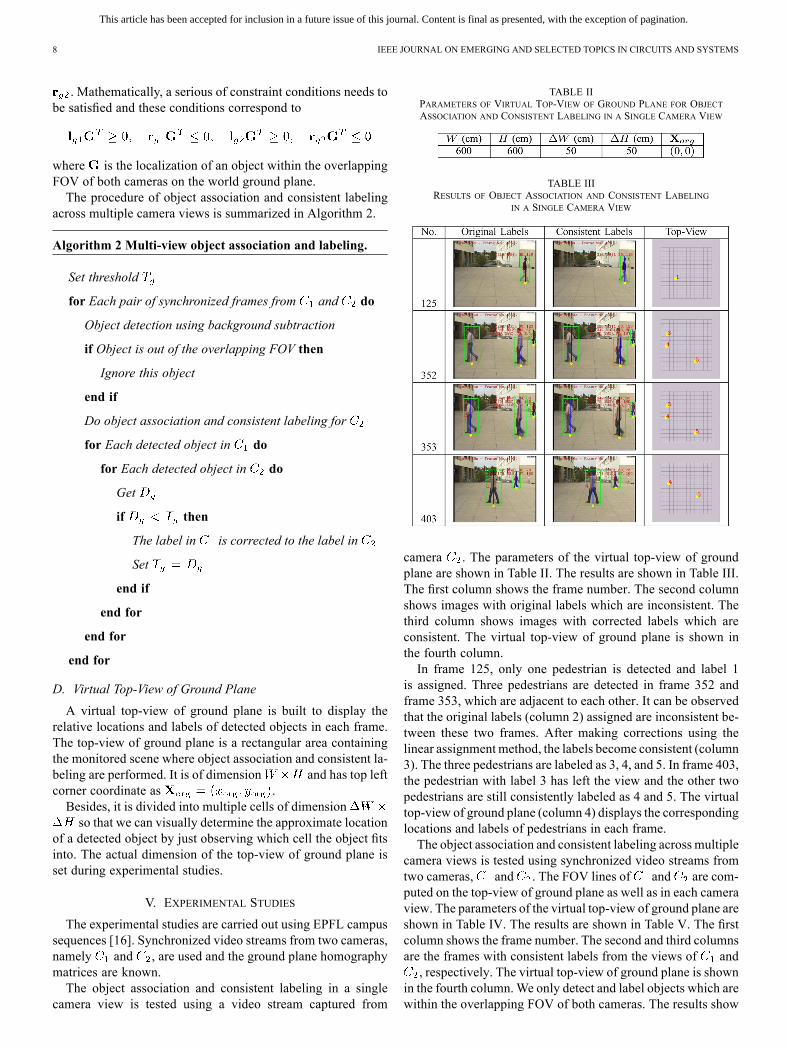
TABLE IIPARAMETERS OF VIRTUAL TOP-VIEW OF GROUND PLANE FOR OBJECTASSOCIATION AND CONSISTENT LABELING IN A SINGLE CAMERA VIEW
TABLE IIIRESULTS OF OBJECT ASSOCIATION AND CONSISTENT LABELING
IN A SINGLE CAMERA VIEW
camera . The parameters of the virtual top-view of groundplane are shown in Table II. The results are shown in Table III.The first column shows the frame number. The second columnshows images with original labels which are inconsistent. Thethird column shows images with corrected labels which areconsistent. The virtual top-view of ground plane is shown inthe fourth column.In frame 125, only one pedestrian is detected and label 1
is assigned. Three pedestrians are detected in frame 352 andframe 353, which are adjacent to each other. It can be observedthat the original labels (column 2) assigned are inconsistent be-tween these two frames. After making corrections using thelinear assignment method, the labels become consistent (column3). The three pedestrians are labeled as 3, 4, and 5. In frame 403,the pedestrian with label 3 has left the view and the other twopedestrians are still consistently labeled as 4 and 5. The virtualtop-view of ground plane (column 4) displays the correspondinglocations and labels of pedestrians in each frame.The object association and consistent labeling across multiple
camera views is tested using synchronized video streams fromtwo cameras, and . The FOV lines of and are com-puted on the top-view of ground plane as well as in each cameraview. The parameters of the virtual top-view of ground plane areshown in Table IV. The results are shown in Table V. The firstcolumn shows the frame number. The second and third columnsare the frames with consistent labels from the views of and, respectively. The virtual top-view of ground plane is shown
in the fourth column.We only detect and label objects which arewithin the overlapping FOV of both cameras. The results show

This article has been accepted for inclusion in a future issue of this journal. Content is final as presented, with the exception of pagination.
DAI AND PAYANDEH: GEOMETRY-BASED OBJECT ASSOCIATION AND CONSISTENT LABELING IN MULTI-CAMERA SURVEILLANCE 9
TABLE IVPARAMETERS OF VIRTUAL TOP-VIEW OF GROUND PLANE FOR OBJECT
ASSOCIATION AND CONSISTENT LABELING ACROSS MULTIPLE CAMERA VIEWS
TABLE VRESULTS OF OBJECT ASSOCIATION AND CONSISTENT LABELING
ACROSS MULTIPLE CAMERA VIEWS
that each object is assigned with a unique label which is consis-tent across different camera views.Throughout experimental studies, we have found that the re-
sults of object association are highly dependent on the accuracyof object detection. As the proposed methods are based on theground plane assumption, it is more important to determine thelocations of human feet in camera views. The morphologicaloperations used during object detection may expand the actualobject silhouettes, and therefore can lead to errors. Furthermore,occlusions are not considered and we assume that objects areseparated from each other. Improvement can be made by addinga module of tracking-based method (e.g., Kalman filtering) afterthe detection step.
VI. CONCLUSION AND FUTURE WORK
This paper focuses on object association across multiple cam-eras and provides solutions for consistent labeling based on themultiple view geometry. The multi-camera calibration deter-mines how pixels on the image plane and space points in thereal world are related. The ground plane homography constraintenables one-to-one mapping between ground points shown indifferent camera views. The FOV lines define boundaries ofcamera FOV and can provide solutions for multi-view objectcorrespondence.The background was modeled as a mixture of adaptive
Gaussian components. A different threshold was selected foreach pixel and these pixel-wise thresholds were adapted bytime. Hence, objects were allowed to become part of the back-ground without destroying the existing background model. In
addition, the follow-up shadow elimination and noise filteringallowed the object contour to be found. Finally, the detectedobjects were represented using tagged bounding boxes.The problems regarding object association and consistent
labeling were addressed through exploring geometrical corre-spondences of objects, not only in a single view, but also acrossmultiple views. The detected objects were represented usinghuman principal axes, which were the vertical lines passingthrough the geometric center of the bounding boxes repre-senting the extracted object silhouettes. A linear assignmentmethod was utilized to correspond objects in sequential framesof a single view and assign consistent labels. In a multi-camerasystem, we used the ground plane homography constraint andFOV lines to find correspondences of objects across differentviews and then correlate the labels in one view to those inanother view. Eventually, the results including object labelsand locations within in the overlapping FOV of cameras weredisplayed in a virtual top-view of ground plane.Following the investigations described in this paper, some fu-
ture work can be taken up to allow the further development.Some extension work can be conducted on the calibration ofPTZ cameras, so that the pan and tilt angles of cameras, as wellas the zooming levels would be incorporated in the equationsrelating image pixels to the real world. In object detection, weassumed that each object was clearly separated from another. Iftwo objects are close enough to each other, their correspondingbounding boxes would merge into a single one. In the future, wewould consider a dense crowd situation where partial or com-plete occlusions exist.
REFERENCES
[1] O. Faugeras and Q.-T. Luong, The Geometry of Multiple Images: TheLaws That Governs the Formation of Multiple Images of a Scene andSome of Their Applications. Cambridge, MA: MIT Press, 2004.
[2] Z. Zhang, “A flexible new technique for camera calibration,” IEEETrans. Pattern Anal. Mach. Intell., vol. 22, no. 11, pp. 1330–1334, Nov.2000.
[3] J.-Y. Bouguet, Camera calibration toolbox for Matlab [Online]. Avail-able: http://www.vision.caltech.edu/bouguet/calib_doc/
[4] T. Ellis, “Multi-camera video surveillance,” in Proc. 36th Int. Car-nahan Conf. Secur. Technol., 2002, pp. 228–233.
[5] T. Ellis, D. Makris, and J. K. Black, “Learning a multi-cameratopology,” in Proc. Joint IEEE Workshop Vis. Surveill. Perform. Eval.Track. Surveill., 2003, pp. 165–171.
[6] D.-W. Seo, H.-U. Chae, B.-W. Kim, W.-H. Choi, and K.-H. Jo,“Human tracking based on multiple view homography,” J. UniversalComput. Sci., vol. 15, no. 13, pp. 2463–2484, 2009.
[7] T. Bouwmans, F. El Baf, and B. Vachon, “Background modeling usingmixture of Gaussians for foreground detection—A survey,” RecentPatents Comput. Sci., vol. 1, no. 3, pp. 219–237, 2008.
[8] C. Stauffer and W. E. L. Grimson, “Adaptive background mixturemodels for real-time tracking,” in IEEE Comput. Soc. Conf. Comput.Vis. Pattern Recognit., 1999, vol. 2, pp. 246–252.
[9] P. KaewTraKulPong and R. Bowden, “An improved adaptive back-ground mixture model for realtime tracking with shadow detection,”in Proc. Eur. Workshop Adv. Video Based Surveill. Syst., 2001, pp.135–144.
[10] Z. Zivkovic, “Improved adaptive Gaussian mixture model for back-ground subtraction,” in Proc. 17th Int. Conf. Pattern Recognit., 2004,vol. 2, pp. 28–31.
[11] S. Khan, O. Javed, Z. Rasheed, and M. Shah, “Human tracking in mul-tiple cameras,” in Proc. 8th IEEE Int. Conf. Comput. Vis., 2001, vol. 1,pp. 331–336.
[12] S. Khan and M. Shah, “Consistent labeling of tracked objects in mul-tiple cameras with overlapping fields of view,” IEEE Trans. PatternAnal. Mach. Intell., vol. 25, no. 10, pp. 1355–1360, Oct. 2003.

This article has been accepted for inclusion in a future issue of this journal. Content is final as presented, with the exception of pagination.
10 IEEE JOURNAL ON EMERGING AND SELECTED TOPICS IN CIRCUITS AND SYSTEMS
[13] S. Velipasalar and W. Wolf, “Multiple object tracking and occlusionhandling by information exchange between uncalibrated cameras,” inProc. IEEE Int. Conf. Image Process., 2005, vol. 2, pp. 418–421.
[14] S. Calderara, A. Prati, R. Vezzani, and R. Cucchiara, “Consistent la-beling for multi-camera object tracking,” in ICIAP 2005, 2005, vol.3617, Lecture Notes in Computer Science, pp. 1206–1214.
[15] G. Kayumbi, P. L. Mazzeo, P. Spagnolo, M. Taj, and A. Cavallaro,“Distributed visual sensing for virtual top-view trajectory generationin football videos,” in Proc. Int. Conf. Content-Based Image Video Re-trieval, 2008, pp. 535–542.
[16] F. Fleuret, J. Berclaz, R. Lengagne, and P. Fua, “Multi-camera peopletracking with a probabilistic occupancy map,” IEEE Trans. PatternAnal. Mach. Intell., vol. 30, no. 2, pp. 267–282, 2008.
[17] R. Hartley and A. Zisserman, Multiple View Geometry in ComputerVision. Cambridge, U.K.: Cambridge Univ. Press, 2003.
[18] Y. Shan, F. Yang, and R. Wang, “Color space selection for movingshadow elimination,” in Proc. 4th Int. Conf. Image Graph., 2007, pp.496–501.
Xiaochen Dai was born in Shanghai, China. Hereceived the B.Eng. degree in electrical engineeringfrom Shanghai Jiao Tong University, Shanghai,China, in 2006, and the M.A.Sc. degree from theSchool of Engineering Science, Simon Fraser Uni-versity, Burnaby, BC, Canada, in 2012.From 2006 to 2008, he was with ASE Shanghai
Inc., working as a software development engineer.His research interests include robotics, image pro-cessing, and machine vision.
Shahram Payandeh received the B.Sc. degree fromUniversity of Akron, Akron, OH, USA, in 1981, andthe M.A.Sc. and Ph.D. degrees from University ofToronto, Toronto, ON, Canada, in 1986 and 1990, re-spectively.He is a Professor in the School of Engineering
Science at Simon Fraser University, Burnaby, BC,Canada. Since 1991, he has been the Director ofExperimental Robotics Laboratory at Simon FraserUniversity. His research interests include networkeddynamical systems, haptic rendering, and medical
robotics.