geomagic touch user guide - s3.amazonaws.com · the geomagic touch enhances productivity and...
TRANSCRIPT
Haptic DeviceGeomagic Touch
User Guide
3D Systems, Inc. 1
TABLE OF CONTENTS
COPYRIGHT 2FCC NOTICE 2COMPLIANCE 2WARRANTY 2LIMITATION OF LIABILITY 2
1 GETTING STARTED 3ABOUT THIS GUIDE 3WHAT COMES WITH YOUR DEVICE 3THE GEOMAGIC TOUCH HAPTIC DEVICE 4SYSTEM REQUIREMENTS 4
2 INSTALLING THE GEOMAGIC TOUCH X DEVICE 5IMPORTANT INFORMATION FOR EXISTING USERS UPGRADING TO GEOMAGIC TOUCH 5INSTALLING THE GEOMAGIC TOUCH DEVICE DRIVERS 5CONNECTING THE GEOMAGIC TOUCH DEVICE 6RUN GEOMAGIC TOUCH SETUP TO IDENTIFY AND PAIR THE DEVICE 8RUN GEOMAGIC TOUCH DIAGNOSTIC TO VERIFY SETUP AND CALIBRATE 9
3 USING THE GEOMAGIC TOUCH DEVICE 10WORKING IN 3D SPACE 10PROPER HANDLING AND POSITIONING OF THE GEOMAGIC TOUCH DEVICE 10PHYSICAL LIMITS OF THE DEVICE 12
4 APPENDIX A: TROUBLESHOOTING 14
5 APPENDIX B: ALTERNATE CONNECTIONS 17ALTERNATE CONNECTION #1: A NETWORK SWITCH IS USED TO CONNECT THE TOUCH AND THE NETWORK 17ALTERNATE CONNECTION #2: TOUCH AND NETWORK ARE CONNECTED TO TWO SEPARATE
ETHERNET PORTS ON THE SAME CARD ON YOUR COMPUTER 19ALTERNATE CONNECTION #3: THE NETWORK IS CONNECTED THROUGH THE TOUCH DEVICE 20ALTERNATE CONNECTION #4: COMPUTER HAS TWO ETHERNET CARDS - ONE CONNECTS
TO THE TOUCH, THE OTHER CONNECTS TO THE NETWORK 21ALTERNATE CONNECTION #5: NETWORK CONNECTED THROUGH WIRELESS - TOUCH CONNECTED
TO COMPUTER ETHERNET PORT 22ALTERNATE CONNECTION #6: NO NETWORK CONNECTION - TOUCH DIRECTLY CONNECTED
TO YOUR COMPUTER 24
6 APPENDIX C: CUSTOMER SUPPORT 26
7 APPENDIX D: REGULATORY NOTICES 27
8 APPENDIX E: CONFIGURING MULTIPLE DEVICES 28DUAL CONFIGURATIONS 28
9 APPENDIX F: GEOMAGIC TOUCH RE-PACKAGING INSTRUCTIONS 29IMPORTANT 29SHIPPING CHECKLIST / PACKING MATERIALS: 29PACKING THE DEVICE AND ACCESSORIES 29
1 APPENDIX G: DEVICE SPECIFICATIONS 30
1
2
3
A
B
E
D
C
F
G
3D Systems, Inc. 2
COPYRIGHT©2014. 3D Systems, Inc. All rights reserved. The content of this manual is furnished for informational use only, is subject to change without notice, and should not be construed as a commitment by 3D Systems, Inc. This document is copyrighted and contains proprietary information that is the property of 3D Systems, Inc. Touch, Geomagic Touch, Geomagic Touch X, Geomagic OpenHaptics, Geomagic, Phantom, Phantom Desktop, Phantom Omni, Sensable, 3D Systems, and the 3D Systems logo are registered trademarks, and Touch is a trademark, of 3D Systems, Inc. Use of the Cubify.com website constitutes acceptance of its Terms of Service and Privacy Policy. Any names, places, and/or events in this publication are not intended to correspond or relate in any way to individuals, groups or associations. Any similarity or likeness of the names, places, and/or events in this publication to those of any individual, living or dead, place, event, or that of any group or association is purely coincidental and unintentional.
FCC NOTICEThis equipment has been tested and found to comply with the limits for a class “B” digital device, pursuant to Part 15 of the FCC Rules. These limits are designed to provide reasonable protection against harmful interference. This equipment generates, uses, and can radiate radio frequency energy and, if not installed and used in accordance with the instruction manual, may cause harmful interference to radio communications. Operation of this equipment in a residential area is likely to cause harmful interference in which case the user will be required to correct the interference at their expense.
COMPLIANCEThis equipment conforms with International Electric Committee (IEC) 60950-1, EN 55022, EN55024, EN 61000-3-2, EN 61000-3-3, and EN 60950 and meets the requirements of the applicable EC directives.
WARRANTYNo warranties of any kind are created or extended by this publication. 3D Systems warrants that the Touch haptic device will be free from defects in materials and workmanship, during the applicable warranty period, when used under the normal conditions described in the documentation provided to you, including the respective User Guide. 3D Systems will promptly repair or replace the Touch, if required, to make it free of defects during the warranty period. This warranty excludes repairs required during the warranty period because of abnormal use or conditions (such as riots, floods, misuse, neglect or improper service by anyone except 3D Systems or its authorized service provider). The warranty period for the Touch is twelve (12) months and shall start the date Your device is purchased. For consumers who are covered by consumer protection laws or regulations in their country of purchase or, if different, their country of residence, the benefits conferred by our standard warranty are in addition to, and operate concurrently with, all rights and remedies conveyed by such consumer protection laws and regulations, including but not limited to these additional rights.
THIS WARRANTY IS THE ONLY WARRANTY PROVIDED FOR THE TOUCH DEVICE. TO THE MAXIMUM EXTENT PERMITTED BY LAW, 3D SYSTEMS EXPRESSLY DISCLAIMS ALL OTHER WARRANTIES FOR THE TOUCH DEVICE AND EACH OF ITS COMPONENTS, WHETHER THOSE WARRANTIES ARE EXPRESS, IMPLIED OR STATUTORY, INCLUDING WARRANTIES OF MERCHANTABILITY AND FITNESS FOR INTENDED OR PARTICULAR PURPOSES.
LIMITATION OF LIABILITY3D SYSTEMS WILL NOT BE RESPONSIBLE FOR CONSEQUENTIAL, EXEMPLARY OR INCIDENTAL DAMAGES (SUCH AS LOSS OF PROFIT OR EMPLOYEE’S TIME) REGARDLESS OF THE REASON. IN NO EVENT SHALL THE LIABILITY AND/OR OBLIGATIONS OF 3D SYSTEMS ARISING OUT OF THE PURCHASE, LEASE, LICENSE AND/OR USE OF THE EQUIPMENT BY YOU OR OTHERS EXCEED THE PURCHASE PRICE OF THE TOUCH DEVICE.

3D Systems, Inc. 3
1 GETTING STARTED
Congratulations on your purchase of the Geomagic® Touch haptic device!
This guide covers information about the Geomagic Touch haptic device. The information contained in this manual was current at the time of publication. Visit http://support.geomagic.com for the latest information.
This chapter describes the following:
• About this guide
• What comes with your device
• The Geomagic Touch haptic device features
• System requirements
ABOUT THIS GUIDEThe Geomagic Touch Device Guide describes the process of installing the required device drivers for your new Geomagic Touch haptic device and connecting the hardware device to your computer. You will also find information on how to use the device and other information about the device.
For the most current device information please visit the Geomagic website at http://support.geomagic.com.
We’ve worked extensively to ensure that the Geomagic Touch device and device drivers install and work smoothly. If you experience any problems during the installation or use of your device, please contact Customer Support.
Please note, if you are installing your device on a supported non-Microsoft® Windows OS, you will find additional information in a separate document that shipped with your software product.
WHAT COMES WITH YOUR DEVICEThe following documentation and other materials are provided to assist you in learning about your haptic device:
The Geomagic Touch haptic device: The Geomagic Touch device uses high-fidelity force feedback to make it possible to touch and manipulate virtual objects.
The Geomagic Touch Quick Start Guide: A quick start to attaching the haptic device, installing the drivers and using the device. For detailed information, see the Geomagic Touch User Guide.
The Geomagic Touch User Guide: This guide (available online at http://support.geomagic.com), describes the process of connecting the haptic device as well as how to work with the device including proper handling, troubleshooting, and device specifications. It also includes the process of installing the device drivers.
RJ45 Ethernet Cable: This cable is used to attach the computer’s Ethernet port to the Geomagic Touch or, one unit to another.
Universal Power Supply: The power supply can be used on any standard circuit, using the supplied power cord.
Power Cord: The power cord connects the Universal Power Supply to the wall outlet.
USB Ethernet Adapter: For connecting the device to an Ethernet Port. The adapter adds a single RJ45 Ethernet Port to a USB-enabled computer system. Support for link speeds of 10/100/1000 Mbps.
1

3D Systems, Inc. 4
THE GEOMAGIC TOUCH HAPTIC DEVICEThe Geomagic Touch enhances productivity and efficiency by enabling the most intuitive human/computer interaction possible, the ability to solve problems by touch.
The Geomagic Touch model is a cost-effective haptic device. The Geomagic Touch system’s high fidelity force feedback senses motion in 6 degrees of freedom providing the best, most realistic 3D Touch sensation for any application. You can feel the point of the stylus in all axes, and track its orientation (pitch, roll and yaw). The Geomagic Touch’s portable design, compact footprint, and an Ethernet port interface ensures quick installation and ease-of-use.
Features• Dexterous Serial manipulator design.
• Six degree-of-freedom positional sensing.
• Portable design and compact footprint for workplace flexibility.
• Compact workspace for ease-of-use.
• Comfortable molded-rubber stylus with textured paint for long term use and secure grip.
• Integrated momentary switch on the stylus for ease of use and end-user customization.
• Automatic workspace calibration based on integrated flags.
• Multi-function indicator light.
• Constructed of metal components and injection-molded plastics.
• Wrist rest to maximize user comfort.
• FCC, CE and RoHS Certified.
• 10/100 MBPS Ethernet compatibility required.
SYSTEM REQUIREMENTSThe Geomagic Touch haptic device requires certain hardware and software components to be able to function properly. This section describes the minimum requirements for operating the Geomagic Touch haptic device.
NOTE: Visit http://support.geomagic.com to get the latest and most complete system requirements for the Geomagic application you will be using with the Geomagic Touch.
• Intel® Core™ 2 Duo or better processor
• RJ45 compliant on-board Ethernet Port or USB Port
• Windows 7 or Windows 8
• 512 MB of free hard disk space
• 2 GB RAM
• The most current version of the Geomagic Touch Device driver. Go to http://support.geomagic.com for specific driver requirements.
• Geomagic supplied RJ45 Ethernet Cable.
• Network card that supports 10/100 MBPS Ethernet compatibility.
3D Systems, Inc. 5
2 INSTALLING THE GEOMAGIC TOUCH X DEVICE
This chapter describes, step by step, how to install the Geomagic Touch haptic device and drivers:
• Install the Geomagic Touch Device Driver software to allow your computer to communicate with the Geomagic Touch device.
• Connect the Geomagic Touch device to your power source and computer.
IMPORTANT INFORMATION FOR EXISTING USERS UPGRADING TO GEOMAGIC TOUCHIf you are an existing user with a PHANToM Desktop and want to upgrade, before you run the Geomagic Touch Setup (on the next page), you must follow these procedures prior to setup.
Uninstall the Previous Version of the Device DriverBefore installing the new Geomagic Touch Device Driver, you MUST first uninstall any previous versions of the Phantom Device Driver (PDD) that you have installed on your system.
1. From the Control Panel, click Programs and Features.
2. Locate, select and uninstall the PHANToM Device Drivers.
3. Install the new Geomagic Touch Device Drivers. See instructions below.
Delete Older Setup FilesDelete all files in the following location:
C:\Users\Public\Documents\SensAble\
INSTALLING THE GEOMAGIC TOUCH DEVICE DRIVERS1. If you have a previous version of the (Phantom) device driver on your system, you MUST manually uninstall the previous version of
the device driver before starting the installation process. See “Uninstall the Previous Version of the Device Driver” on page 8.
2. Insert the product DVD or download the Geomagic Touch Device Driver from the http://support.geomagic.com website. (Go to http://support.geomagic.com, from Products select Scanners and Hardware, then select the Touch device and Downloads).
NOTE: As with most other software packages, you must have administrator privileges on the machine in order to install system software.
3. If the installation wizard does not start, you will need to manually start the installation. Using Windows Explorer, locate and double-click the Install Wizardx.exe file.
4. Follow the Install Wizard to start the installation of the Geomagic Touch Device Driver.
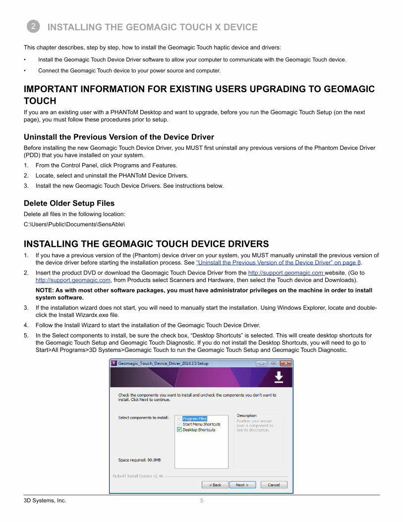
5. In the Select components to install, be sure the check box, “Desktop Shortcuts” is selected. This will create desktop shortcuts for the Geomagic Touch Setup and Geomagic Touch Diagnostic. If you do not install the Desktop Shortcuts, you will need to go to Start>All Programs>3D Systems>Geomagic Touch to run the Geomagic Touch Setup and Geomagic Touch Diagnostic.
2

3D Systems, Inc. 6
CONNECTING THE GEOMAGIC TOUCH DEVICEIn this section you will setup the Geomagic Touch and plug in all of the cables. The following steps detail the Geomagic recommended connection (Connection Setup below). The device requires certified Category 5 or higher ethernet cables.
NOTE: Exact appearance of your equipment may vary from that shown in the figures.Connection Setup
1. Position the Geomagic Touch device in your workspace, using both hands to grasp the covers and base of the device. See “PROPER HANDLING AND POSITIONING OF THE GEOMAGIC TOUCH DEVICE” on page 10 for instructions on how to handle the device to reduce the risk of damage.
For a computer with no internet connection, follow the Driver Installation instructions found on page 2 of the Ethernet Adapter manual (that came with your adapter).
2. Connect the Ethernet Adapter, if you have not already installed the driver – wait a few minutes for the driver to be automatically installed (you must have an internet connection).
3. Connect the Geomagic Touch Device (Ethernet cable and power supply) as shown below. Connect the Ethernet cable to the Adapter and then to either the ETH 1 or ETH 2 ports on the device.

3D Systems, Inc. 7
4. Connect the power supply as follows:
a. Hook up the Power Supply (use only the supplied power supply with the Geomagic Touch device). Plug the power cord into the power supply.
b. Plug the power cord into an available outlet (for 110V the outlet must be rated for at least 2 Amps, for 220V: 1 Amp). The green status light on the power supply indicates that it is working correctly. Finally plug the power connector into the connector (Power) on the back of Geomagic Touch device.
Connect the Ethernet cord and power cable to the back of the Touch device.
5. Allow 1-2 minutes for the device to automatically configure the Device Drivers with your Operating System and connect.
NOTE: This configuration only occurs the first time you connect your device.6. Ensure that the Geomagic Touch Status Indicator Light is lit (it will either be blinking yellow or solid orange if working properly). If it
is not, check all of the connections. If the problem persists, contact Customer Support.

3D Systems, Inc. 8
RUN GEOMAGIC TOUCH SETUP TO IDENTIFY AND PAIR THE DEVICEIn this section you will identify your Geomagic Touch device and pair it with your host PC. This process only needs to be executed once. There is a safety key exchange during the pairing process. The safety key will be saved to host PC hard drive and the NV-Ram of the Geomagic Touch after the pairing process is properly done.
NOTE: For existing users, see the following section before proceeding, “IMPORTANT INFORMATION FOR EXISTING USERS UPGRADING TO GEOMAGIC TOUCH” on page 5.1. Double-click the Geomagic Touch Setup icon on your desktop, or if you chose not to install desktop shortcuts click Start>All
Programs>3D Systems>Geomagic Touch>Geomagic Touch Setup.
2. Make sure that the correct Geomagic Touch Model (Touch) is selected on the Hardware tab. From the Host Name drop-down list on the Hardware Tab, do the following:
a. Match the name of the device or the serial number on the bottom of the device with a device in the list. 3. After you have identified your device you will need to lock or “Pair” it with your host PC.
4. Click the Pairing button.
A meter appears counting down the amount of time you have to press the Pair button on the back of your Geomagic Touch device.
5. Press the Pair button on the back of your Geomagic Touch device. The device and your computer are now paired together.
NOTE: If you run out of time, a timeout error appears. Repeat steps 4 and 5 again. NOTE: You will only need to Pair the device again if you move the device to a different computer.6. Click OK to apply the pairing and exit the Setup dialog.
The Geomagic Touch Setup Window
CPU IP Address

3D Systems, Inc. 9
RUN GEOMAGIC TOUCH DIAGNOSTIC TO VERIFY SETUP AND CALIBRATEIn this section you will run the Geomagic Touch Diagnostic application to confirm that the device is properly connected and installed.
1. Click the Geomagic Touch Diagnostic icon on your desktop, or if you chose not to install desktop shortcuts click Start>All Programs>3D Systems>Geomagic Touch>Geomagic Touch Diagnostic.
2. The Geomagic Touch Diagnostic application will open and you will be in the Mode dialog.
3. Click the Next arrow in the bottom right of the dialog or click the Select tab to move on to the next step.
4. The Select tab initializes the Geomagic Touch device and begins to run to the Servoloop. Click the Next arrow when the six remaining test tabs appear in the dialog to move on to the Calibration stage.
5. You will have to place the stylus in the ink well to properly calibrate the device. The icon changes from red to green when the calibration is complete.
6. Click Next to move on the next test.
7. The Read Encoder dialog displays the range of the devices read and gimbal encoders.
8. The Cycle Amps tab will cycle the device amps. When the results dialog states that the device amplifiers are OK click Next to move on to the next test.
9. The Test Forces dialog contains a slider for the Motor DAC values and a Celsius field to estimate the heat of motors using a determined force. When you are comfortable with the motor levels click Next to move on to the Box Test.
10. On the Box Test dialog, take the stylus and move it around the box in the dialog. You will notice a Force meter on the right hand side that displays the force in Newtons. Click Next to move on to the Servoloop.
11. The final diagnostic is the Servoloop. The Servoloop demonstrates statistics on the timing intervals of the servo loop; these statistics are then written to this dialog (you can copy and send to support if needed). The device driver requires by default that the haptic device forces be updated at a rate of 1000 times a second (1000 Hz).

3D Systems, Inc. 10
3 USING THE GEOMAGIC TOUCH DEVICE
This chapter introduces you to working with the Geomagic Touch haptic device and the physical limits of the device’s range of motion. It is important to understand these limitations so that you do not inadvertently damage the device by forcing it past its designed limits.
WORKING IN 3D SPACEWe have become so accustomed to using a mouse to move around a computer monitor that we don’t think twice as we move our hand around a desk to move the cursor on the computer screen. But there was a time not long ago when this seemingly simple task was not second nature; some even found it challenging and were often frustrated as they learned. If you are new to working in 3D digital space and haptics, working with the Geomagic Touch device may take a little getting used to. Understanding where objects are in 3D space may take some practice before you are able to move and manipulate objects with ease and certainty. Be patient with yourself.
PROPER HANDLING AND POSITIONING OF THE GEOMAGIC TOUCH DEVICEWARNING Gripping and lifting the Geomagic Touch device improperly may damage it. To reduce the risk of damage, please follow the instructions below.
Handling the Geomagic Touch DeviceCalibrating the device: The Geomagic Touch may need to be recalibrated from time to time, particularly if it has lost power. To calibrate the device, place the stylus in the inkwell and start your haptically enabled application. The indicator light in the inkwell of the Geomagic Touch device will be lit a steady blue when the device is properly calibrated. Alternatively, you can use the Geomagic Touch Diagnostic utility (Start>All Programs>3D Systems>Geomagic Touch).
Lifting the device: To properly lift the device grasp the base of the Geomagic Touch unit on both sides and lift as shown in the image below. DO NOT lift by grasping the stylus or arm. The stylus is detachable by design. Lifting the unit by the stylus or arm could result in severe damage to the device.
Position hands to securely fit the device.
Lifting the stylus out of the inkwell: Grasp the end of the stylus and lift UP, to disengage, and then OUT as show below in the image on the left. Do NOT attempt to pull the stylus straight out as shown on the right.
Be sure to lift the stylus in a two step motion.
3
3D Systems, Inc. 11
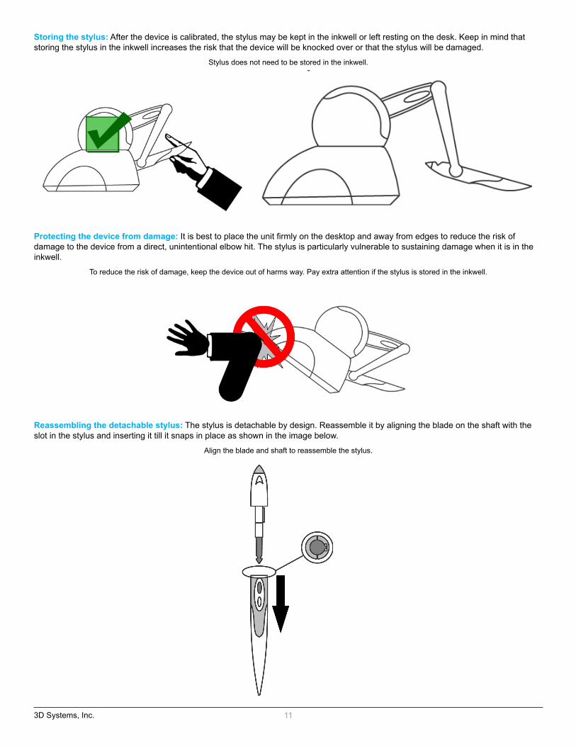
Storing the stylus: After the device is calibrated, the stylus may be kept in the inkwell or left resting on the desk. Keep in mind that storing the stylus in the inkwell increases the risk that the device will be knocked over or that the stylus will be damaged.
Stylus does not need to be stored in the inkwell.
Protecting the device from damage: It is best to place the unit firmly on the desktop and away from edges to reduce the risk of damage to the device from a direct, unintentional elbow hit. The stylus is particularly vulnerable to sustaining damage when it is in the inkwell.
To reduce the risk of damage, keep the device out of harms way. Pay extra attention if the stylus is stored in the inkwell.
Reassembling the detachable stylus: The stylus is detachable by design. Reassemble it by aligning the blade on the shaft with the slot in the stylus and inserting it till it snaps in place as shown in the image below.
Align the blade and shaft to reassemble the stylus.
3D Systems, Inc. 12
Positioning the Geomagic Touch DeviceThe correct placement of the device will vary from one user to another. You may want to experiment to find a placement that feels right for you.
• The device should be positioned so that you are comfortable when working with it.
• You should not feel any strain on your wrist or forearm when working with the device.
• If you are left-handed, you may find it easier to work with the Geomagic Touch placed to the left of the keyboard.
• Remember to take breaks often to stretch your hands, wrists, and elbows.
PHYSICAL LIMITS OF THE DEVICEThe Geomagic Touch device has six degrees of motion provided by six axis points. All the degrees of motion have physical limits. When you reach one of these limits you will feel a sudden stop; this is the mechanical stop designed into the device. Forcing the device past any of these stops risks damaging the device.
Take some time to become more familiar with the physical limits of the Geomagic Touch before using the device by moving the device through its full range of motion at each axis point.
1. First make sure the device is not active; the inkwell should not be lit. If the inkwell is lit, close any haptic applications you have open.
2. Grasp the stylus as you would a pen, with the free end of the stylus (the eraser end of a pencil) pointing toward you and the point of the stylus (the end connected to the arm) pointing toward the unit. Using the following illustration as a guide, gently move the stylus in all directions to feel each mechanical stop.
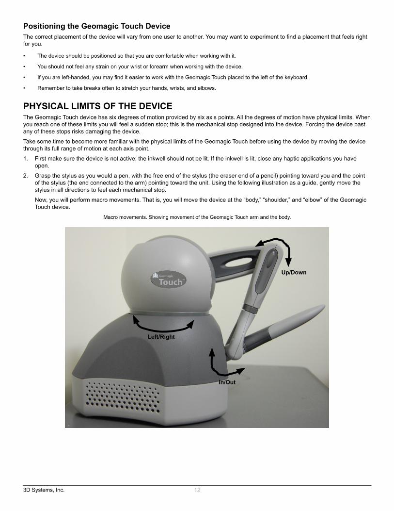
Now, you will perform macro movements. That is, you will move the device at the “body,” “shoulder,” and “elbow” of the Geomagic Touch device.
Macro movements. Showing movement of the Geomagic Touch arm and the body.
Up/Down
In/Out
Left/Right
3D Systems, Inc. 13
3. Perform macro movements, as follows:
a. Start with large-but gentle-movements. See the Figure above. Beginning at the top, move the arm of the device left/right. The body, sometimes referred to as the turret, of the Geomagic Touch device will pivot until it reaches a physical limit. Again, do not try to force the device past any of the mechanical stops.
b. Next, move the stylus up/down. The primary movement will happen in the shoulder of the Geomagic Touch device.c. Next move it in/out with the primary movement happening in the elbow. When you reach a physical limit, you’ll feel one of the
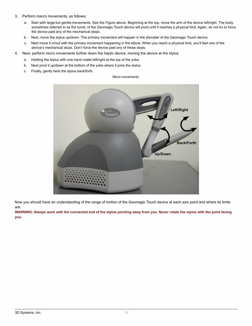
device’s mechanical stops. Don’t force the device past any of these stops.4. Next, perform micro movements further down the haptic device, moving the device at the stylus.
a. Holding the stylus with one hand rotate left/right at the top of the yoke. b. Next pivot it up/down at the bottom of the yoke where it joins the stylus. c. Finally, gently twist the stylus back/forth.
Micro movements.
Now you should have an understanding of the range of motion of the Geomagic Touch device at each axis point and where its limits are.WARNING: Always work with the connected end of the stylus pointing away from you. Never rotate the stylus with the point facing you.
Back/Forth
Up/Down
Left/Right

3D Systems, Inc. 14
4 APPENDIX A: TROUBLESHOOTING
This section provides tips for correcting some common problems encountered with the Geomagic Touch device. If after following these steps, you cannot resolve the problem, please contact Customer Support (see “6 APPENDIX C: Customer Support”).
#1 - The Geomagic Touch light does not come on at all.The light on the Geomagic Touch device should be on if it is receiving power. Check that the power supply is plugged into a working outlet (the light on the power supply should be green if it is). Then check that the connection between the power supply and the Geomagic Touch device is made correctly.
#2 - The light on the Geomagic Touch device is orange.This is not a problem. When the device is powered and properly calibrated it will be orange to let you know that it is receiving power.
#3 - When running a demonstration or application, the light on the Geomagic Touch flashes green.This indicates that your Geomagic Touch may not be properly calibrated. This can happen if you unplug it. To re-calibrate the device, follow the steps to “RUN GEOMAGIC TOUCH DIAGNOSTIC TO VERIFY SETUP AND CALIBRATE”, found in Chapter 2. If you are unable to calibrate the device using these steps, please contact Customer Support.
#4 - When I start a demo I get an error.This can happen if the device is not plugged in properly or is not configured properly. Execute the following steps, checking at each point for proper operation:
• Verify power supply - Check to make sure the Geomagic Touch device is plugged in properly. The light on the device will be lit (and possi-bly flashing) if power is being provided.
• Verify Ethernet port connection - Make sure that you have the Ethernet port cable plugged into the Geomagic Touch device. Make sure you have the other end plugged into the Ethernet port on your computer.
• Verify matched settings between the Geomagic Touch device and computer: - From the Start menu, select All Programs>3D Systems>Geomagic Touch>Geomagic Touch Setup. You will be presented with a
dialog box for configuring your device. Ensure that Touch is chosen as the device model.
#5 - I am able to start a demonstration application; but even though the light is solid green, the device behaves strangely when I move it around in a scene.It is possible that there is a defect or a loose connection inside the Geomagic Touch device. DO NOT ATTEMPT TO OPEN THE DEVICE. Contact Customer Support. When contacting Support, you may be asked to run the “Geomagic Touch Diagnostic” utility to help with diagnosis. To start the Geomagic Touch Diagnostic, go to the Start menu and select All Programs>3D Systems>Geomagic Touch>Geomagic Touch Diagnostic (or there should be a shortcut on the desktop).
The following describes the basic features of this diagnostic utility which you should be prepared to run:
• Select the Geomagic Touch device which you want to test. Usually this will be “Default Device.”
• Read Encoders - The values being sensed for the positions and rotations of the device are dynamically displayed in the window. The stylus switch is ON when you press the button. The presence switch is ON when you hold the rubber stylus handle. The picture of the Geomagic Touch should change dynamically as you move the stylus around.
• Cycle Amps - This will simply turn the amplifiers off then on again repeatedly to test their functioning.
• Test Forces - IMPORTANT: Hold onto the stylus when executing this test. Move the sliders with your mouse to generate forces which push against your hand. X controls force parallel to the table. Y controls force up and down. Z controls force in and out.
• Box Test - Provides a box which you can feel with your Geomagic Touch device. The sides of the box should feel flat and the corners sharp.
• Quit - Quits the diagnostic utility.
4A
3D Systems, Inc. 15
#6 - I cannot find my Geomagic Touch device in the Geomagic Touch Setup dialog.It may take a few minutes for the computer to detect the Ethernet card. If the network icon shows “Acquiring Network Address” status, wait. If the status changes to “Limited or no connectivity” your host PC may have a multi-adapter configuration.You can go to the Geomagic Touch LAN tab to select the proper adapter first then start the pairing process. To set the adapter, follow these steps:• Go to the Geomagic Touch LAN tab.
• Select the target Geomagic Touch from tree view then press the Select Adapter button to set proper adapter.
• In the Host Adapter Interface select the adapter card that the Geomagic Touch is connected to.
• Click the Pairing button.
• Optionally, press the stylus button on your Geomagic Touch Device, if the Press Down check box changes selection state in the Geo-magic Touch Lan tab, then you have selected the correct device.
• Press the Pair button on the back of your device. The device and your computer are now paired together.
#7 - I cannot Pair my Geomagic Touch device.A specific device service instance will not be tied to one single IP address. With DHCP and LLA (Link Local Addressing) it is not safe to assume that any service instance will have the same IP address tomorrow. Addresses can change. The actual IP address and port number of a given device service instance will change more frequently. The device driver automatically tries to resolve the current ad-dress of the device service instance that the user chooses prior to using it. Currently the device driver implements a custom built mDNS browser and resolver. If under any circumstances, the device driver is not able to resolve a valid IP address or if there is an IP conflict with another computer on the network, then simply power cycling (disconnect and reconnect the power cord) the device will renew its IP address.
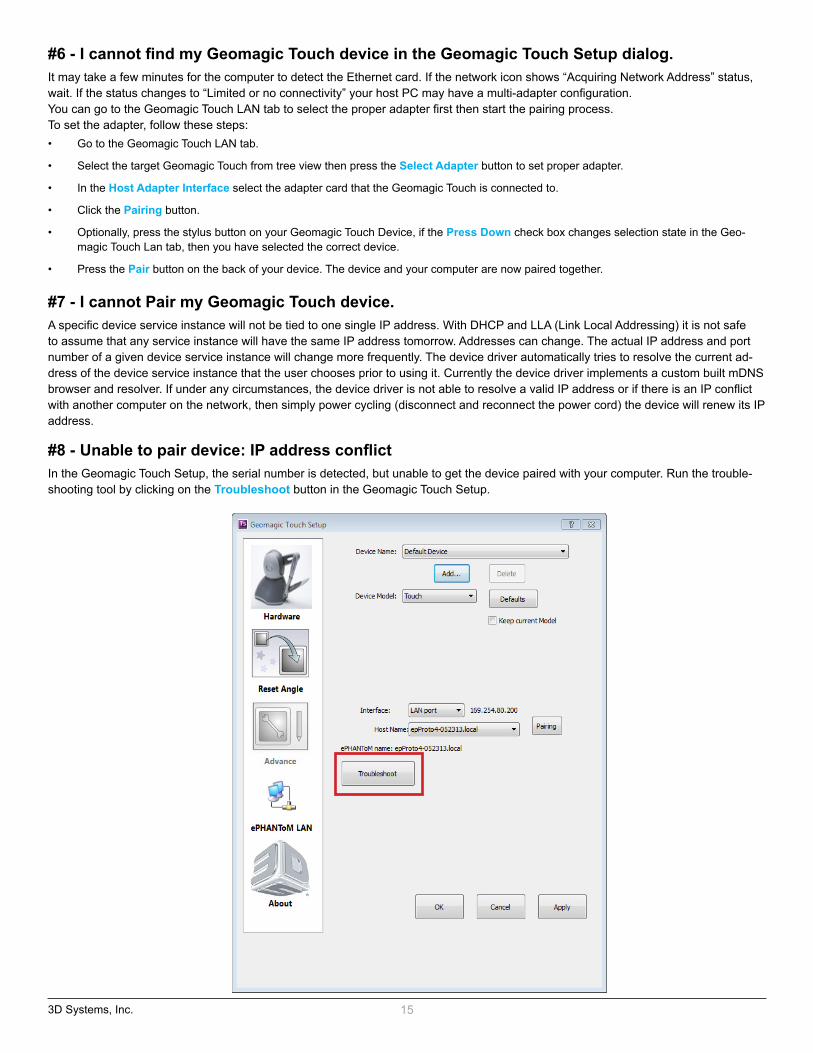
#8 - Unable to pair device: IP address conflictIn the Geomagic Touch Setup, the serial number is detected, but unable to get the device paired with your computer. Run the trouble-shooting tool by clicking on the Troubleshoot button in the Geomagic Touch Setup.

3D Systems, Inc. 16
Type in the Touch MAC address, which can be found on the bottom of the device. Click the DETECT button in the troubleshooting win-dow. If you see Conflict Detected! a conflict for IP Address is detected on your system. NOTE: An IP address conflict occurs when two network devices on a LAN (local area network) or the Internet have been assigned the same IP address.
To resolve the IP Address Conflict, unplug the power cable connecting to the Touch device, and then plug the cable back in. By doing that, Touch should obtain a new IP address. Wait about 2 minutes for network to reconfigure and obtain the new IP address. And then run the troubleshooting tool to confirm the issue has been addressed.

3D Systems, Inc. 17
5 APPENDIX B: ALTERNATE CONNECTIONS
This section explains the alternate connection options for the Geomagic Touch device.
Exact appearance of your equipment may vary from that shown in the figures. The device requires certified Category 5 or higher ethernet cables.
ALTERNATE CONNECTION #1: A NETWORK SWITCH IS USED TO CONNECT THE TOUCH AND THE NETWORK
NOTE: A network switch has to support 100 mbps connection.1. Position the Geomagic Touch device in your workspace, using both hands to grasp the covers and base of the device. See
“PROPER HANDLING AND POSITIONING OF THE GEOMAGIC TOUCH DEVICE” on page 10 for instructions on how to handle the device to reduce the risk of damage.
2. Attach the straight end of a supplied Ethernet Cable to any Ethernet Port on the supplied Network Switch.
3. Connect an Ethernet Cable from any port on the Network Switch to the Ethernet connector (ETH1 or ETH2) on the back of the Geomagic Touch.
4. Connect an Ethernet Cable from any port on the Network Switch to the appropriate Port on your computer.
B

3D Systems, Inc. 18
5. Connect the power supply as follows:
a. Hook up the Power Supply (use only the supplied power supply with the Geomagic Touch device):b. Plug the power cord into the power supply. Plug the power cord into an available outlet (for 110V the outlet must be rated for at least
2 Amps, for 220V: 1 Amp). The green status light on the power supply indicates that it is working correctly. Finally plug the power connector into the connector (Power) on the back of Geomagic Touch device.
Connect the Ethernet cords and power cable to the back of the Touch device.
6. Allow 1-2 minutes for the device to automatically configure the Device Drivers with your Operating System and connect.
NOTE: This configuration only occurs the first time you connect your device.7. Ensure that the Geomagic Touch Status Indicator Light is lit (it will either be blinking yellow or solid orange if working properly). If it
is not, check all of the connections. If the problem persists, contact Customer Support.

3D Systems, Inc. 19
ALTERNATE CONNECTION #2: TOUCH AND NETWORK ARE CONNECTED TO TWO SEPARATE ETHERNET PORTS ON THE SAME CARD ON YOUR COMPUTER
1. Position the Geomagic Touch device in your workspace, using both hands to grasp the covers and base of the device. See “PROPER HANDLING AND POSITIONING OF THE GEOMAGIC TOUCH DEVICE” on page 10 for instructions on how to handle the device to reduce the risk of damage. Connect an Ethernet Cable from a wall jack to an Ethernet Port on your computer.
2. Connect an Ethernet Cable from a port on your computer to an Ethernet Port (ETH1 or ETH2) on the back of the Touch.
3. Connect the power supply as follows:
a. Hook up the Power Supply (use only the supplied power supply with the Geomagic Touch device).b. Plug the power cord into the power supply. Plug the power cord into an available outlet (for 110V the outlet must be rated for at least
2 Amps, for 220V: 1 Amp). The green status light on the power supply indicates that it is working correctly. Finally plug the power connector into the connector (Power) on the back of Geomagic Touch device.
Connect the Ethernet cords and power cable to the back of the Touch device.
3D Systems, Inc. 20
4. Allow 1-2 minutes for the device to automatically configure the Device Drivers with your Operating System and connect.
NOTE: This configuration only occurs the first time you connect your device.5. Ensure that the Geomagic Touch Status Indicator Light is lit (it will either be blinking yellow or solid orange if working properly). If it
is not, check all of the connections. If the problem persists, contact Customer Support.
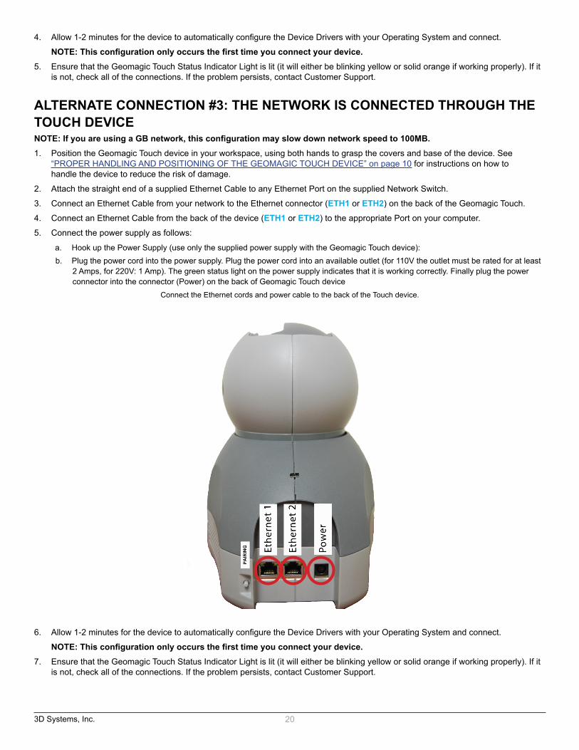
ALTERNATE CONNECTION #3: THE NETWORK IS CONNECTED THROUGH THE TOUCH DEVICENOTE: If you are using a GB network, this configuration may slow down network speed to 100MB.1. Position the Geomagic Touch device in your workspace, using both hands to grasp the covers and base of the device. See
“PROPER HANDLING AND POSITIONING OF THE GEOMAGIC TOUCH DEVICE” on page 10 for instructions on how to handle the device to reduce the risk of damage.
2. Attach the straight end of a supplied Ethernet Cable to any Ethernet Port on the supplied Network Switch.
3. Connect an Ethernet Cable from your network to the Ethernet connector (ETH1 or ETH2) on the back of the Geomagic Touch.
4. Connect an Ethernet Cable from the back of the device (ETH1 or ETH2) to the appropriate Port on your computer.
5. Connect the power supply as follows:
a. Hook up the Power Supply (use only the supplied power supply with the Geomagic Touch device):b. Plug the power cord into the power supply. Plug the power cord into an available outlet (for 110V the outlet must be rated for at least
2 Amps, for 220V: 1 Amp). The green status light on the power supply indicates that it is working correctly. Finally plug the power connector into the connector (Power) on the back of Geomagic Touch device
Connect the Ethernet cords and power cable to the back of the Touch device.
6. Allow 1-2 minutes for the device to automatically configure the Device Drivers with your Operating System and connect.
NOTE: This configuration only occurs the first time you connect your device. 7. Ensure that the Geomagic Touch Status Indicator Light is lit (it will either be blinking yellow or solid orange if working properly). If it
is not, check all of the connections. If the problem persists, contact Customer Support.

3D Systems, Inc. 21
ALTERNATE CONNECTION #4: COMPUTER HAS TWO ETHERNET CARDS - ONE CONNECTS TO THE TOUCH, THE OTHER CONNECTS TO THE NETWORK
1. Position the Geomagic Touch device in your workspace, using both hands to grasp the covers and base of the device. See “PROPER HANDLING AND POSITIONING OF THE GEOMAGIC TOUCH DEVICE” on page 10 for instructions on how to handle the device to reduce the risk of damage. Connect an Ethernet Cable from a wall jack to an Ethernet Port on your computer.
2. Connect an Ethernet Cable from a port on your computer to an Ethernet Port (ETH1 or ETH2) on the back of the Touch.
3. Connect an Ethernet Cable from a port on your computer to the network (wall jack).
4. Connect the power supply as follows:
a. Hook up the Power Supply (use only the supplied power supply with the Geomagic Touch device):b. Plug the power cord into the power supply. Plug the power cord into an available outlet (for 110V the outlet must be rated for at least
2 Amps, for 220V: 1 Amp). The green status light on the power supply indicates that it is working correctly. Finally plug the power connector into the connector (Power) on the back of Geomagic Touch device.
Connect the Ethernet cords and power cable to the back of the Touch device.
3D Systems, Inc. 22
5. Allow 1-2 minutes for the device to automatically configure the Device Drivers with your Operating System and connect.
NOTE: This configuration only occurs the first time you connect your device.6. Ensure that the Geomagic Touch Status Indicator Light is lit (it will either be blinking yellow or solid orange if working properly). If it
is not, check all of the connections. If the problem persists, contact Customer Support.
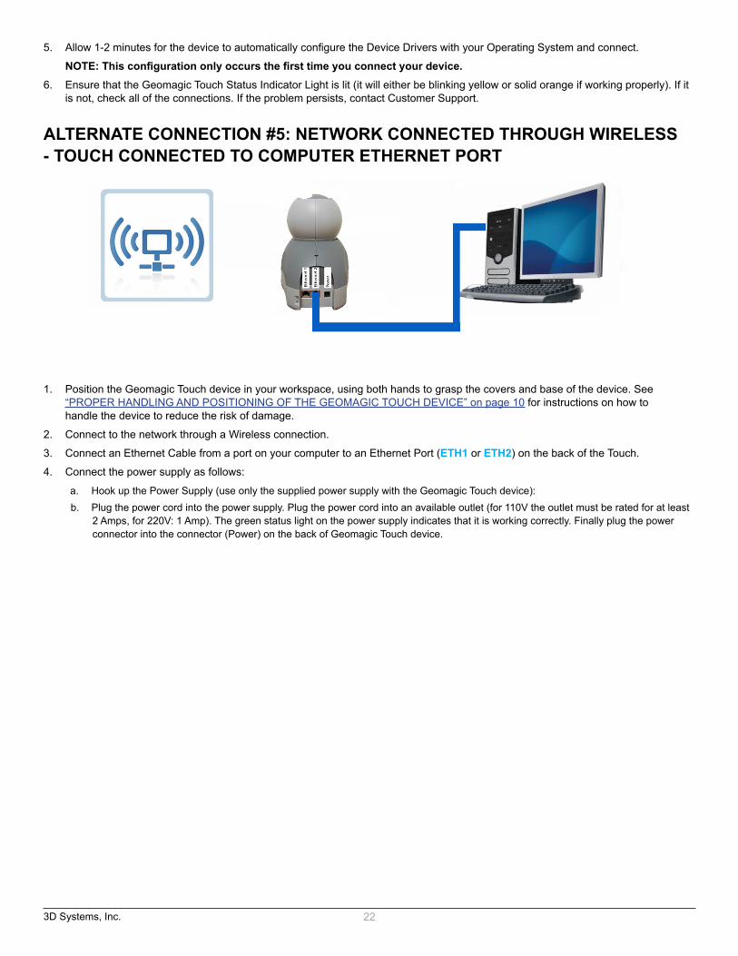
ALTERNATE CONNECTION #5: NETWORK CONNECTED THROUGH WIRELESS - TOUCH CONNECTED TO COMPUTER ETHERNET PORT
1. Position the Geomagic Touch device in your workspace, using both hands to grasp the covers and base of the device. See “PROPER HANDLING AND POSITIONING OF THE GEOMAGIC TOUCH DEVICE” on page 10 for instructions on how to handle the device to reduce the risk of damage.
2. Connect to the network through a Wireless connection.
3. Connect an Ethernet Cable from a port on your computer to an Ethernet Port (ETH1 or ETH2) on the back of the Touch.
4. Connect the power supply as follows:
a. Hook up the Power Supply (use only the supplied power supply with the Geomagic Touch device):b. Plug the power cord into the power supply. Plug the power cord into an available outlet (for 110V the outlet must be rated for at least
2 Amps, for 220V: 1 Amp). The green status light on the power supply indicates that it is working correctly. Finally plug the power connector into the connector (Power) on the back of Geomagic Touch device.

3D Systems, Inc. 23
Connect the Ethernet cords and power cable to the back of the Touch device.
5. Allow 1-2 minutes for the device to automatically configure the Device Drivers with your Operating System and connect.
NOTE: This configuration only occurs the first time you connect your device.6. Ensure that the Geomagic Touch Status Indicator Light is lit (it will either be blinking yellow or solid orange if working properly). If it
is not, check all of the connections. If the problem persists, contact Customer Support.
3D Systems, Inc. 24
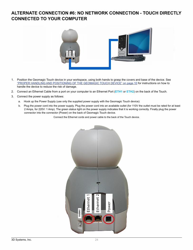
ALTERNATE CONNECTION #6: NO NETWORK CONNECTION - TOUCH DIRECTLY CONNECTED TO YOUR COMPUTER
1. Position the Geomagic Touch device in your workspace, using both hands to grasp the covers and base of the device. See “PROPER HANDLING AND POSITIONING OF THE GEOMAGIC TOUCH DEVICE” on page 10 for instructions on how to handle the device to reduce the risk of damage.
2. Connect an Ethernet Cable from a port on your computer to an Ethernet Port (ETH1 or ETH2) on the back of the Touch.
3. Connect the power supply as follows:
a. Hook up the Power Supply (use only the supplied power supply with the Geomagic Touch device):b. Plug the power cord into the power supply. Plug the power cord into an available outlet (for 110V the outlet must be rated for at least
2 Amps, for 220V: 1 Amp). The green status light on the power supply indicates that it is working correctly. Finally plug the power connector into the connector (Power) on the back of Geomagic Touch device.
Connect the Ethernet cords and power cable to the back of the Touch device.

3D Systems, Inc. 25
4. Allow 1-2 minutes for the device to automatically configure the Device Drivers with your Operating System and connect.
NOTE: This configuration only occurs the first time you connect your device.5. Ensure that the Geomagic Touch Status Indicator Light is lit (it will either be blinking yellow or solid orange if working properly). If it
is not, check all of the connections. If the problem persists, contact Customer Support.

3D Systems, Inc. 26
6 APPENDIX C: CUSTOMER SUPPORT
WARNING: DO NOT OPEN THE DEVICE. Attempting to open or repair the device by anyone other than a certified authorized service center voids the manufacturer warranty and hardware maintenance contract. There are no serviceable components in the Geomagic Touch device or power supply. Return to 3D Systems for servicing.
If you encounter any difficulties within your warranty period, you can obtain Technical Support through the three channels listed below. If you are out of warranty and do not have active maintenance, Technical Support is limited.
If you purchased your Geomagic Touch device from a distributor, please contact them first.
• Visit the support section at http://support.geomagic.com/
• E-mail: [email protected]
• Customer Support can also be reached via telephone: 1-978-494-8241
C

3D Systems, Inc. 27
7 APPENDIX D: REGULATORY NOTICES
FCC Notice (U.S. Only)The Geomagic Touch haptic device is classified by the Federal Communications Commission (FCC) as a Class B digital device.
NOTE: This equipment has been tested and found to comply with the limits for a Class B digital device, pursuant to part 15 of the FCC Rules. These limits are designed to provide reasonable protection against harmful interference in a residential installation. This equipment generates, uses and can radiate radio frequency energy and, if not installed and used in accordance with the instructions, may cause harmful interference to radio communications. However, there is no guarantee that interference will not occur in a particular installation. If this equipment does cause harmful interference to radio or television reception, which can be determined by turning the equipment off and on, the user is encouraged to try to correct the interference by one or more of the following measures:
• Reorient or relocate the receiving antenna.
• Increase the separation between the equipment and receiver.
• Connect the equipment into an outlet on a circuit different from that to which the receiver is connected.
• Consult the dealer or an experienced radio/TV technician for help. Modifications not expressly approved by the manufacturer could void the user’s authority to operate the equipment under FCC rules.
The following information is provided on the device covered in this document in compliance with FCC regulations:
Product Name: Geomagic Touch
Model Number: 02350
Company Name: 3D Systems, Inc.
NOTES Any changes or modifications to the hardware not expressly approved by 3D Systems, Inc. could void the user’s authority to operate this equipment.
Canadian Requirements:
Canadian Department of Communications Radio Interference RegulationsThis digital apparatus, the Geomagic Touch haptic device, does not exceed the Class B limits for radio-noise emissions from digital apparatus as set out in the Radio Interference Regulations of the Canadian Department of Communications.
Règlement sur le brouillage radioélectrique du ministère des Communications
Cet appareil numérique, the Geomagic Touch haptic device, respecte les limites de bruits radioélectriques visant les appareils numériques de classe B prescrites dans le Règlement sur le brouillage radioélectrique du ministère des Communications du Canada.
European Requirements:
EN 55022 StatementThis is to certify that the Geomagic Touch haptic device is shielded against the generation of radio interference in accordance with the application of Council Directive 89/336/EEC, Article 4a. Conformity is declared by the application of EN 55022 Class B (CISPR 22).
WARNING This is a Class B product. In a domestic environment, this product may cause radio interference, in which case, the user may be required to take appropriate measures.
ACHTUNG: Dieses ist ein Gerät der Funkstörgrenzwertklasse B. In Wohnbereichen können bei Betrieb dieses Gerätes Rundfunkstörungen auftreten, in welchen Fällen der Benutzer für entsprechende Gegenmaßnahmen verantwortlich ist.
ATTENTION: Ceci est un produit de Classe B. Dans un environnement domestique, ce produit risque de créer des interférences radioélectriques, il appartiendra alors à l’utilisateur de prendre les mesures spécifiques appropriées.
D

3D Systems, Inc. 28
8 APPENDIX E: CONFIGURING MULTIPLE DEVICES
If you want to use more than one Geomagic Touch haptic device with your computer, you can create as many as 20 uniquely named Geomagic Touch configurations. Each named Geomagic Touch configuration can refer to a particular system configuration that you use frequently. Which device to use is defined by the software application which uses it.
To create a new Geomagic Touch configuration use the Geomagic Touch Setup utility.
1. From the Start menu, select All Programs>3D Systems>Geomagic Touch>Geomagic Touch Setup.
The Geomagic Touch Setup window opens.
2. On the hardware tab, click Add.
3. Type a specific name to call that device, click OK.
4. From the Geomagic Touch model menu, select the correct model. 5. Click OK.
DUAL CONFIGURATIONSThe Dual Configuration settings only apply if you want to set up a pair of Geomagic Touch devices to work in tandem with each other. With one of the Geomagic Touch devices connected to the computer, daisy chain the second device by connecting the supplied Ethernet cable from one Geomagic Touch device to the other.
E

3D Systems, Inc. 29
9 APPENDIX F: GEOMAGIC TOUCH RE-PACKAGING INSTRUCTIONS
If you need to transport or ship the device, please follow these packaging guidelines to reduce the risk of damage to the device.
IMPORTANTRemember the Geomagic Touch device is a sensitive piece of electronic equipment and must be handled with care. Lifting the device by any of the moving parts may adversely affect the unit’s performance and risks damaging the device. The Geomagic Touch device has a limited range of motion. Forcing the device past these limits risks damaging the device. If you have not already done so, please review “PROPER HANDLING AND POSITIONING OF THE GEOMAGIC TOUCH DEVICE” on page 10.
SHIPPING CHECKLIST / PACKING MATERIALS:You will need the following items to ship the device safely.
The packaging materials in which the device was originally shipped:
• 1 Medium shipping box
• 1 Set of foam inserts (cradles the device)
• Shipping Tray
• Packing tape
PACKING THE DEVICE AND ACCESSORIES• If necessary, reassemble the box and arrange the foam inserts.
- Fit the bottom foam insert into the bottom of the box.
• Orient the Geomagic Touch device to fit neatly inside the foam insert. You may need to grasp the Geomagic Touch device by the upper arm—the piece with the oblong cutout— in order to position it properly. DO NOT grab the stylus.
• Gently lower the Geomagic Touch device into the insert, while maintaining alignment of the Geomagic Touch arm to the cutout.
• Ensure that the Geomagic Touch device is fully seated by pressing firmly on the Geomagic Touch label.
• Check to see that the Geomagic Touch arm is fully seated by carefully pressing on the elbow joint.
• Place the top half of foam insert over the Geomagic Touch device.
• Place the stylus, power supply, power cord, and Ethernet cable into the Shipping Tray on the top of the foam insert.
• Place the Shipping Tray over the foam insert.
• Close the box and tape shut.
F

3D Systems, Inc. 30
G 10 APPENDIX G: DEVICE SPECIFICATIONS
Product specifications are subject to change without notice.
Force Feedback Workspace~ 6.4 W x 4.8 H
x 2.8 D in> 160 W x 120 H x 70 d mm
Footprint (physical area the base of the device occupies on a surface) ~ 6 5/8 W x 8 D in ~ 168 W x 203 D mm
Weight (device only) 3 lbs 15 oz ~1.42 kgRange of Motion Hand movement pivoting at wristNominal Position Resolution > 450 dpi ~0.055 mmBackdrive Friction < 1 oz < 0.26 NMaximum Exertable Force (at nominal orthogonal arms position) .75 lbf 3.3 N
Continuous Exertable Force (24 hrs) > 0.2 lbf > .88 N
Stiffness
X axis > 7.3 lbs./in
Y axis > 13.4 lbs./in
Z axis > 5.9 lbs./in
X axis > 1.26 N/ mm
Y axis > 2.31 N/mm
Z axis > 1.02 N/mmInertia (apparent mass at tip) ~ 0.101 lbm ~ 45 gForce Feedback X, Y, ZPosition Sensing X, Y, Z (digital encoders)Stylus gimbal Pitch, roll, yaw (± 5% linearity potentiometers)Interface RJ45 compliant on-board Ethernet Port or USB PortSupported platforms Intel or AMD-based PCsOpenHaptics® SDK compatibility? Yes
* Please visit the Support and Resources section of our website for more information (http://support.geomagic.com).