general specifications analog i/o modules specifications analog i/o modules yokogawa electric...
TRANSCRIPT
GeneralSpecifications
<<Contents>> <<Index>>
Analog I/O Modules
Yokogawa Electric Corporation2-9-32, Nakacho, Musashino-shi, Tokyo, 180-8750 JapanTel.: 81-422-52-5616 URL: http://www.stardom.biz
GS 34P02Q31-01E
GS 34P02Q31-01E©Copyright Nov.12, 2001(YK)23rd Edition Oct. 1, 2017(YK)
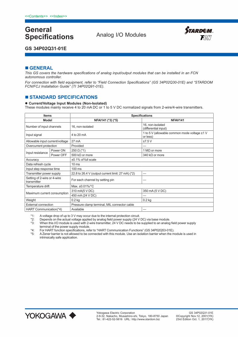
n GENERALThis GS covers the hardware specifications of analog input/output modules that can be installed in an FCN autonomous controller. For connection with field equipment, refer to “Field Connection Specifications” (GS 34P02Q30-01E) and “STARDOM FCN/FCJ Installation Guide” (TI 34P02Q91-01E).
n STANDARD SPECIFICATIONSl Current/Voltage Input Modules (Non-Isolated)These modules mainly receive 4 to 20 mA DC or 1 to 5 V DC normalized signals from 2-wire/4-wire transmitters.
Items Specifications Model NFAI141 (*3) (*5) NFAV141
Number of input channels 16, non-isolated 16, non-isolated (differential input)
Input signal 4 to 20 mA 1 to 5 V (allowable common mode voltage ±1 V or less)
Allowable input current/voltage 27 mA ±7.5 V Overcurrent protection Provided —
Input resistancePower ON 250 Ω (*1) 1 MΩ or morePower OFF 500 kΩ or more 340 kΩ or more
Accuracy ±0.1% of full scaleData refresh cycle 10 msInput step response time 100 msTransmitter power supply 22.8 to 26.4 V (output current limit: 27 mA) (*2) — Setting of 2-wire or 4-wire transmitter For each channel by setting pin —
Temperature drift Max. ±0.01%/°C
Maximum current consumption310 mA(5 V DC) 350 mA (5 V DC)450 mA (24 V DC) —
Weight 0.2 kg 0.2 kg External connection Pressure clamp terminal, MIL connector cableHART Communication(*4) Available —
*1: A voltage drop of up to 3 V may occur due to the internal protection circuit.*2: Depends on the actual voltage applied by analog field power supply (24 V DC) via base module.*3: When this I/O module is used with 2-wire transmitter, 24 V DC needs to be supplied to an analog field power supply
terminal of the power supply module.*4: For HART function specifications, refer to “HART Communication Functions” (GS 34P02Q53-01E).*5: A Zener barrier is not allowed to be connected with this module. Use an isolation barrier when the module is used in
intrinsically safe application.
2
All Rights Reserved. Copyright © 2001, Yokogawa Electric Corporation
<<Contents>> <<Index>>
GS 34P02Q31-01E Nov. 30, 2015-00
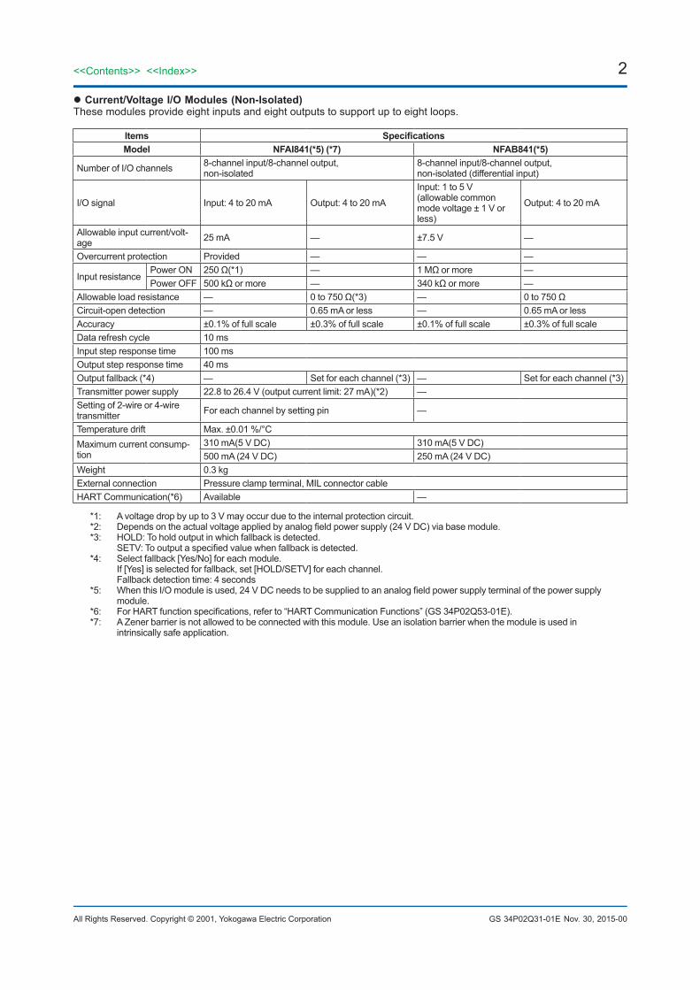
l Current/Voltage I/O Modules (Non-Isolated)These modules provide eight inputs and eight outputs to support up to eight loops.
Items SpecificationsModel NFAI841(*5) (*7) NFAB841(*5)
Number of I/O channels 8-channel input/8-channel output, non-isolated
8-channel input/8-channel output, non-isolated (differential input)
I/O signal Input: 4 to 20 mA Output: 4 to 20 mA
Input: 1 to 5 V (allowable common mode voltage ± 1 V or less)
Output: 4 to 20 mA
Allowable input current/volt-age 25 mA — ±7.5 V —
Overcurrent protection Provided — — —
Input resistancePower ON 250 Ω(*1) — 1 MΩ or more —Power OFF 500 kΩ or more — 340 kΩ or more —
Allowable load resistance — 0 to 750 Ω(*3) — 0 to 750 Ω Circuit-open detection — 0.65 mA or less — 0.65 mA or less Accuracy ±0.1% of full scale ±0.3% of full scale ±0.1% of full scale ±0.3% of full scale Data refresh cycle 10 msInput step response time 100 ms Output step response time 40 ms Output fallback (*4) — Set for each channel (*3) — Set for each channel (*3) Transmitter power supply 22.8 to 26.4 V (output current limit: 27 mA)(*2) — Setting of 2-wire or 4-wire transmitter For each channel by setting pin —
Temperature drift Max. ±0.01 %/°CMaximum current consump-tion
310 mA(5 V DC) 310 mA(5 V DC)500 mA (24 V DC) 250 mA (24 V DC)
Weight 0.3 kgExternal connection Pressure clamp terminal, MIL connector cableHART Communication(*6) Available —
*1: A voltage drop by up to 3 V may occur due to the internal protection circuit.*2: Depends on the actual voltage applied by analog field power supply (24 V DC) via base module. *3: HOLD: To hold output in which fallback is detected. SETV: To output a specified value when fallback is detected.*4: Select fallback [Yes/No] for each module. If [Yes] is selected for fallback, set [HOLD/SETV] for each channel. Fallback detection time: 4 seconds*5: When this I/O module is used, 24 V DC needs to be supplied to an analog field power supply terminal of the power supply
module.*6: For HART function specifications, refer to “HART Communication Functions” (GS 34P02Q53-01E).*7: A Zener barrier is not allowed to be connected with this module. Use an isolation barrier when the module is used in
intrinsically safe application.
3<<Contents>> <<Index>>
All Rights Reserved. Copyright © 2001, Yokogawa Electric Corporation GS 34P02Q31-01E Oct. 1, 2015-00
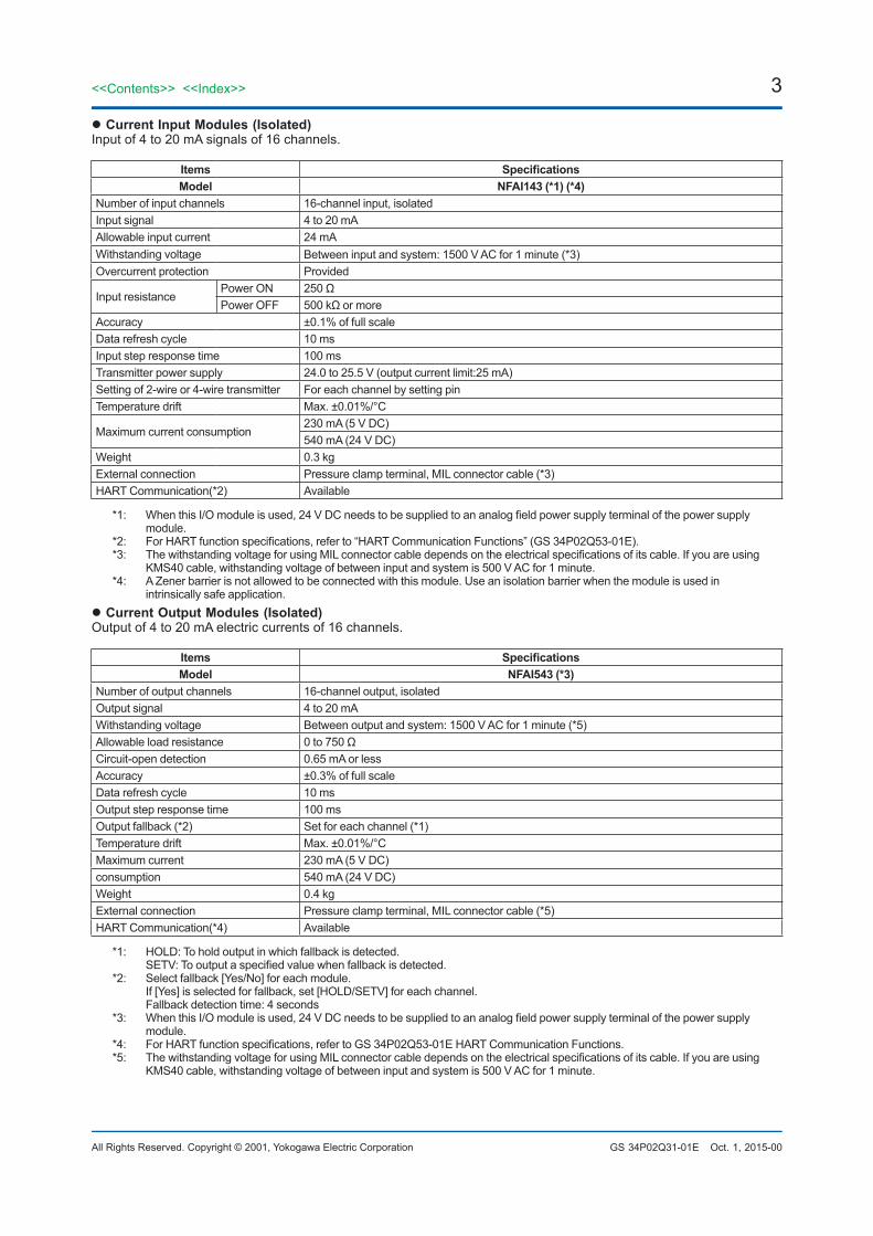
l Current Input Modules (Isolated)Input of 4 to 20 mA signals of 16 channels.
Items Specifications Model NFAI143 (*1) (*4)
Number of input channels 16-channel input, isolated Input signal 4 to 20 mA Allowable input current 24 mA Withstanding voltage Between input and system: 1500 V AC for 1 minute (*3) Overcurrent protection Provided
Input resistance Power ON 250 Ω Power OFF 500 kΩ or more
Accuracy ±0.1% of full scale Data refresh cycle 10 ms Input step response time 100 ms Transmitter power supply 24.0 to 25.5 V (output current limit:25 mA) Setting of 2-wire or 4-wire transmitter For each channel by setting pin Temperature drift Max. ±0.01%/°C
Maximum current consumption 230 mA (5 V DC) 540 mA (24 V DC)
Weight 0.3 kg External connection Pressure clamp terminal, MIL connector cable (*3) HART Communication(*2) Available
*1: When this I/O module is used, 24 V DC needs to be supplied to an analog field power supply terminal of the power supply module.
*2: For HART function specifications, refer to “HART Communication Functions” (GS 34P02Q53-01E).*3: The withstanding voltage for using MIL connector cable depends on the electrical specifications of its cable. If you are using
KMS40 cable, withstanding voltage of between input and system is 500 V AC for 1 minute.*4: A Zener barrier is not allowed to be connected with this module. Use an isolation barrier when the module is used in
intrinsically safe application.l Current Output Modules (Isolated)Output of 4 to 20 mA electric currents of 16 channels.
Items Specifications Model NFAI543 (*3)
Number of output channels 16-channel output, isolated Output signal 4 to 20 mA Withstanding voltage Between output and system: 1500 V AC for 1 minute (*5) Allowable load resistance 0 to 750 Ω Circuit-open detection 0.65 mA or less Accuracy ±0.3% of full scale Data refresh cycle 10 ms Output step response time 100 ms Output fallback (*2) Set for each channel (*1) Temperature drift Max. ±0.01%/°C Maximum current 230 mA (5 V DC) consumption 540 mA (24 V DC) Weight 0.4 kg External connection Pressure clamp terminal, MIL connector cable (*5) HART Communication(*4) Available
*1: HOLD: To hold output in which fallback is detected. SETV: To output a specified value when fallback is detected.*2: Select fallback [Yes/No] for each module. If [Yes] is selected for fallback, set [HOLD/SETV] for each channel. Fallback detection time: 4 seconds*3: When this I/O module is used, 24 V DC needs to be supplied to an analog field power supply terminal of the power supply
module.*4: For HART function specifications, refer to GS 34P02Q53-01E HART Communication Functions.*5: The withstanding voltage for using MIL connector cable depends on the electrical specifications of its cable. If you are using
KMS40 cable, withstanding voltage of between input and system is 500 V AC for 1 minute.
4
All Rights Reserved. Copyright © 2001, Yokogawa Electric Corporation
<<Contents>> <<Index>>
GS 34P02Q31-01E
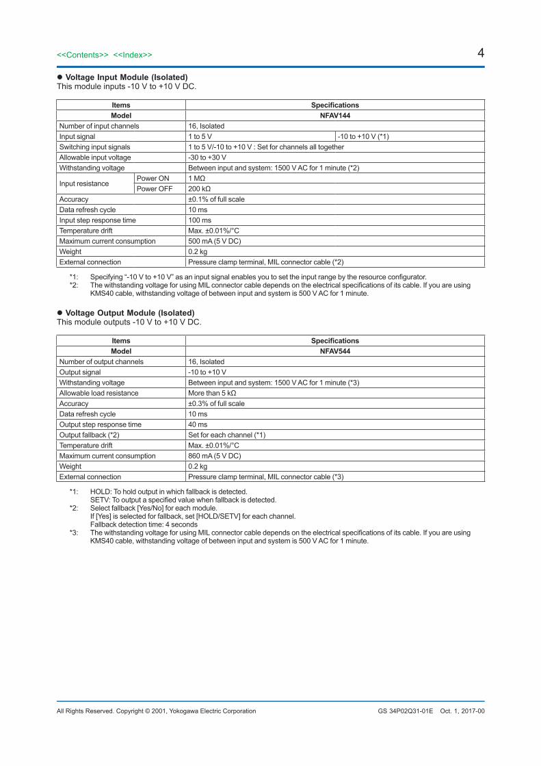
l Voltage Input Module (Isolated)This module inputs -10 V to +10 V DC.
Items Specifications Model NFAV144
Number of input channels 16, Isolated Input signal 1 to 5 V -10 to +10 V (*1) Switching input signals 1 to 5 V/-10 to +10 V : Set for channels all together Allowable input voltage -30 to +30 V Withstanding voltage Between input and system: 1500 V AC for 1 minute (*2)
Input resistancePower ON 1 MΩ Power OFF 200 kΩ
Accuracy ±0.1% of full scale Data refresh cycle 10 ms Input step response time 100 ms Temperature drift Max. ±0.01%/°C Maximum current consumption 500 mA (5 V DC) Weight 0.2 kg External connection Pressure clamp terminal, MIL connector cable (*2)
*1: Specifying “-10 V to +10 V” as an input signal enables you to set the input range by the resource configurator.*2: The withstanding voltage for using MIL connector cable depends on the electrical specifications of its cable. If you are using
KMS40 cable, withstanding voltage of between input and system is 500 V AC for 1 minute.
l Voltage Output Module (Isolated)This module outputs -10 V to +10 V DC.
Items Specifications Model NFAV544
Number of output channels 16, Isolated Output signal -10 to +10 V Withstanding voltage Between input and system: 1500 V AC for 1 minute (*3) Allowable load resistance More than 5 kΩ Accuracy ±0.3% of full scale Data refresh cycle 10 ms Output step response time 40 ms Output fallback (*2) Set for each channel (*1) Temperature drift Max. ±0.01%/°C Maximum current consumption 860 mA (5 V DC) Weight 0.2 kg External connection Pressure clamp terminal, MIL connector cable (*3)
*1: HOLD: To hold output in which fallback is detected. SETV: To output a specified value when fallback is detected.*2: Select fallback [Yes/No] for each module. If [Yes] is selected for fallback, set [HOLD/SETV] for each channel. Fallback detection time: 4 seconds*3: The withstanding voltage for using MIL connector cable depends on the electrical specifications of its cable. If you are using
KMS40 cable, withstanding voltage of between input and system is 500 V AC for 1 minute.
Oct. 1, 2017-00
5<<Contents>> <<Index>>
All Rights Reserved. Copyright © 2001, Yokogawa Electric Corporation GS 34P02Q31-01E
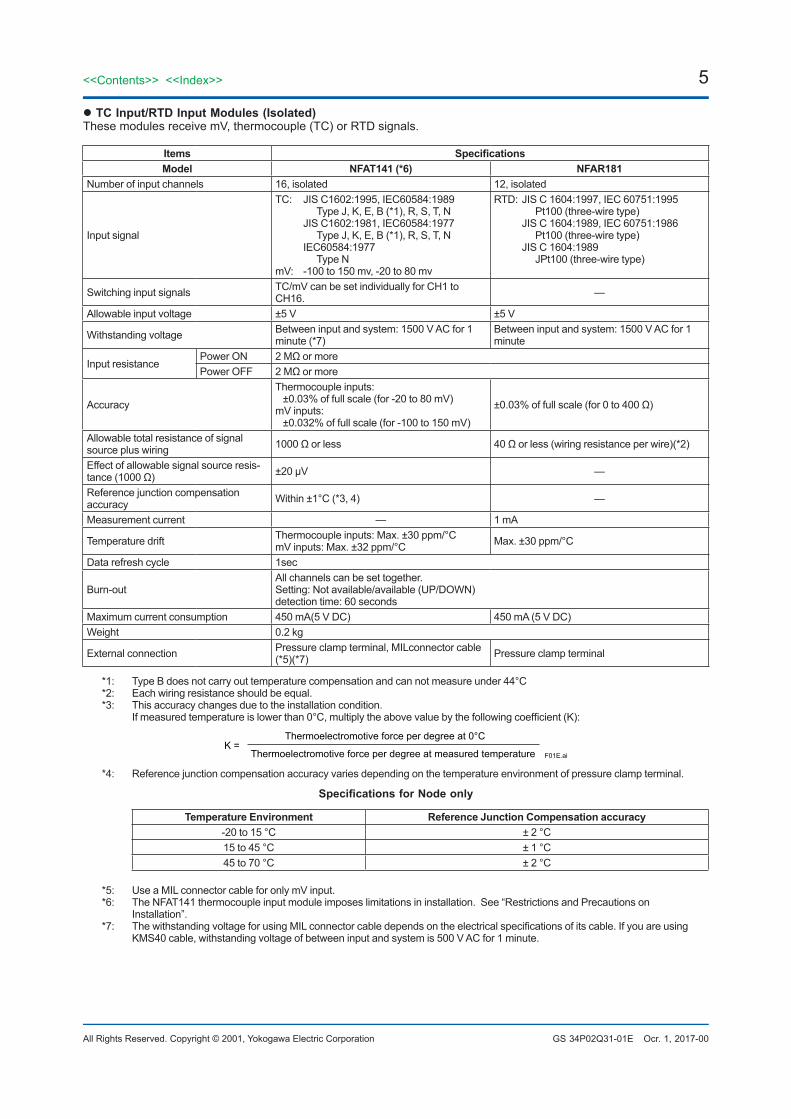
l TC Input/RTD Input Modules (Isolated)These modules receive mV, thermocouple (TC) or RTD signals.
Items Specifications Model NFAT141 (*6) NFAR181
Number of input channels 16, isolated 12, isolated
Input signal
TC: JIS C1602:1995, IEC60584:1989 Type J, K, E, B (*1), R, S, T, N JIS C1602:1981, IEC60584:1977 Type J, K, E, B (*1), R, S, T, N IEC60584:1977 Type N mV: -100 to 150 mv, -20 to 80 mv
RTD: JIS C 1604:1997, IEC 60751:1995 Pt100 (three-wire type) JIS C 1604:1989, IEC 60751:1986 Pt100 (three-wire type) JIS C 1604:1989 JPt100 (three-wire type)
Switching input signals TC/mV can be set individually for CH1 to CH16. —
Allowable input voltage ±5 V ±5 V
Withstanding voltage Between input and system: 1500 V AC for 1 minute (*7)
Between input and system: 1500 V AC for 1 minute
Input resistancePower ON 2 MΩ or morePower OFF 2 MΩ or more
Accuracy
Thermocouple inputs: ±0.03% of full scale (for -20 to 80 mV)
mV inputs: ±0.032% of full scale (for -100 to 150 mV)
±0.03% of full scale (for 0 to 400 Ω)
Allowable total resistance of signal source plus wiring 1000 Ω or less 40 Ω or less (wiring resistance per wire)(*2)
Effect of allowable signal source resis-tance (1000 Ω) ±20 μV —
Reference junction compensation accuracy Within ±1°C (*3, 4) —
Measurement current — 1 mA
Temperature drift Thermocouple inputs: Max. ±30 ppm/°C mV inputs: Max. ±32 ppm/°C Max. ±30 ppm/°C
Data refresh cycle 1sec
Burn-outAll channels can be set together. Setting: Not available/available (UP/DOWN) detection time: 60 seconds
Maximum current consumption 450 mA(5 V DC) 450 mA (5 V DC)Weight 0.2 kg
External connection Pressure clamp terminal, MILconnector cable (*5)(*7) Pressure clamp terminal
*1: Type B does not carry out temperature compensation and can not measure under 44°C*2: Each wiring resistance should be equal.*3: This accuracy changes due to the installation condition. If measured temperature is lower than 0°C, multiply the above value by the following coefficient (K):
K =Thermoelectromotive force per degree at measured temperature
Thermoelectromotive force per degree at 0°C
F01E.ai
*4: Reference junction compensation accuracy varies depending on the temperature environment of pressure clamp terminal.
Specifications for Node only
Temperature Environment Reference Junction Compensation accuracy -20 to 15 °C ± 2 °C15 to 45 °C ± 1 °C 45 to 70 °C ± 2 °C
*5: Use a MIL connector cable for only mV input.*6: The NFAT141 thermocouple input module imposes limitations in installation. See “Restrictions and Precautions on
Installation”.*7: The withstanding voltage for using MIL connector cable depends on the electrical specifications of its cable. If you are using
KMS40 cable, withstanding voltage of between input and system is 500 V AC for 1 minute.
Ocr. 1, 2017-00
6
All Rights Reserved. Copyright © 2001, Yokogawa Electric Corporation
<<Contents>> <<Index>>
GS 34P02Q31-01E
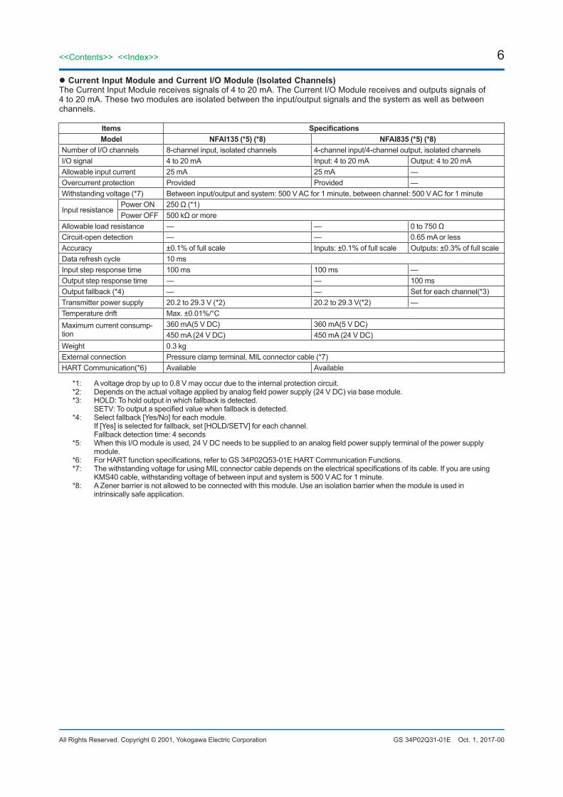
l Current Input Module and Current I/O Module (Isolated Channels)The Current Input Module receives signals of 4 to 20 mA. The Current I/O Module receives and outputs signals of 4 to 20 mA. These two modules are isolated between the input/output signals and the system as well as between channels.
Items Specifications Model NFAI135 (*5) (*8) NFAI835 (*5) (*8)
Number of I/O channels 8-channel input, isolated channels 4-channel input/4-channel output, isolated channels I/O signal 4 to 20 mA Input: 4 to 20 mA Output: 4 to 20 mAAllowable input current 25 mA 25 mA —Overcurrent protection Provided Provided —Withstanding voltage (*7) Between input/output and system: 500 V AC for 1 minute, between channel: 500 V AC for 1 minute
Input resistance Power ON 250 Ω (*1)Power OFF 500 kΩ or more
Allowable load resistance — — 0 to 750 Ω Circuit-open detection — — 0.65 mA or less Accuracy ±0.1% of full scale Inputs: ±0.1% of full scale Outputs: ±0.3% of full scale Data refresh cycle 10 msInput step response time 100 ms 100 ms — Output step response time — — 100 ms Output fallback (*4) — — Set for each channel(*3) Transmitter power supply 20.2 to 29.3 V (*2) 20.2 to 29.3 V(*2) — Temperature drift Max. ±0.01%/°CMaximum current consump-tion
360 mA(5 V DC) 360 mA(5 V DC) 450 mA (24 V DC) 450 mA (24 V DC)
Weight 0.3 kgExternal connection Pressure clamp terminal, MIL connector cable (*7)HART Communication(*6) Available Available
*1: A voltage drop by up to 0.8 V may occur due to the internal protection circuit.*2: Depends on the actual voltage applied by analog field power supply (24 V DC) via base module. *3: HOLD: To hold output in which fallback is detected. SETV: To output a specified value when fallback is detected.*4: Select fallback [Yes/No] for each module. If [Yes] is selected for fallback, set [HOLD/SETV] for each channel. Fallback detection time: 4 seconds*5: When this I/O module is used, 24 V DC needs to be supplied to an analog field power supply terminal of the power supply
module.*6: For HART function specifications, refer to GS 34P02Q53-01E HART Communication Functions.*7: The withstanding voltage for using MIL connector cable depends on the electrical specifications of its cable. If you are using
KMS40 cable, withstanding voltage of between input and system is 500 V AC for 1 minute.*8: A Zener barrier is not allowed to be connected with this module. Use an isolation barrier when the module is used in
intrinsically safe application.
Oct. 1, 2017-00
7<<Contents>> <<Index>>
All Rights Reserved. Copyright © 2001, Yokogawa Electric Corporation GS 34P02Q31-01E
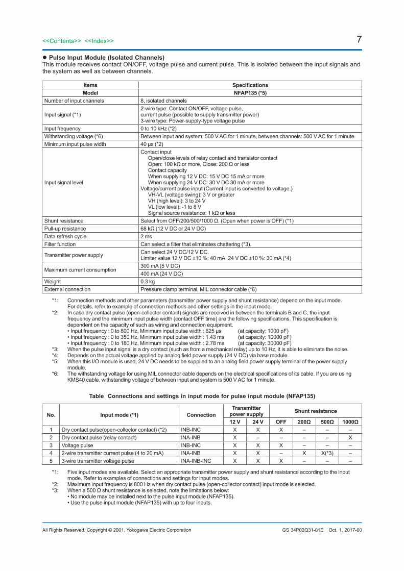
l Pulse Input Module (Isolated Channels)This module receives contact ON/OFF, voltage pulse and current pulse. This is isolated between the input signals and the system as well as between channels.
Items Specifications Model NFAP135 (*5)
Number of input channels 8, isolated channels
Input signal (*1)2-wire type: Contact ON/OFF, voltage pulse, current pulse (possible to supply transmitter power) 3-wire type: Power-supply-type voltage pulse
Input frequency 0 to 10 kHz (*2)Withstanding voltage (*6) Between input and system: 500 V AC for 1 minute, between channels: 500 V AC for 1 minuteMinimum input pulse width 40 μs (*2)
Input signal level
Contact input Open/close levels of relay contact and transistor contact Open: 100 kΩ or more, Close: 200 Ω or less Contact capacity When supplying 12 V DC: 15 V DC 15 mA or more When supplying 24 V DC: 30 V DC 30 mA or more Voltage/current pulse input (Current input is converted to voltage.) VH-VL (voltage swing): 3 V or greater VH (high level): 3 to 24 V VL (low level): -1 to 8 V Signal source resistance: 1 kΩ or less
Shunt resistance Select from OFF/200/500/1000 Ω. (Open when power is OFF) (*1)Pull-up resistance 68 kΩ (12 V DC or 24 V DC)Data refresh cycle 2 msFilter function Can select a filter that eliminates chattering (*3).
Transmitter power supply Can select 24 V DC/12 V DC. Limiter value 12 V DC ±10 %: 40 mA, 24 V DC ±10 %: 30 mA (*4)
Maximum current consumption300 mA (5 V DC)400 mA (24 V DC)
Weight 0.3 kgExternal connection Pressure clamp terminal, MIL connector cable (*6)
*1: Connection methods and other parameters (transmitter power supply and shunt resistance) depend on the input mode. For details, refer to example of connection methods and other settings in the input mode.*2: In case dry contact pulse (open-collector contact) signals are received in between the terminals B and C, the input
frequency and the minimum input pulse width (contact OFF time) are the following specifications. This specification is dependent on the capacity of such as wiring and connection equipment.
• Input frequency : 0 to 800 Hz, Minimum input pulse width : 625 μs (at capacity: 1000 pF) • Input frequency : 0 to 350 Hz, Minimum input pulse width : 1.43 ms (at capacity: 10000 pF) • Input frequency : 0 to 180 Hz, Minimum input pulse width : 2.78 ms (at capacity: 30000 pF)*3: When the pulse input signal is a dry contact (such as from a mechanical relay) up to 10 Hz, it is able to eliminate the noise.*4: Depends on the actual voltage applied by analog field power supply (24 V DC) via base module.*5: When this I/O module is used, 24 V DC needs to be supplied to an analog field power supply terminal of the power supply
module.*6: The withstanding voltage for using MIL connector cable depends on the electrical specifications of its cable. If you are using
KMS40 cable, withstanding voltage of between input and system is 500 V AC for 1 minute.
Table Connections and settings in input mode for pulse input module (NFAP135)
No. Input mode (*1) Connection Transmitter
power supply Shunt resistance
12 V 24 V OFF 200Ω 500Ω 1000Ω1 Dry contact pulse(open-collector contact) (*2) INB-INC X X X – – – 2 Dry contact pulse (relay contact) INA-INB X – – – – X 3 Voltage pulse INB-INC X X X – – – 4 2-wire transmitter current pulse (4 to 20 mA) INA-INB X X – X X(*3) – 5 3-wire transmitter voltage pulse INA-INB-INC X X X – – –
*1: Five input modes are available. Select an appropriate transmitter power supply and shunt resistance according to the input mode. Refer to examples of connections and settings for input modes.
*2: Maximum input frequency is 800 Hz when dry contact pulse (open-collector contact) input mode is selected.*3: When a 500 Ω shunt resistance is selected, note the limitations below: • No module may be installed next to the pulse input module (NFAP135). • Use the pulse input module (NFAP135) with up to four inputs.
Oct. 1, 2017-00
8
All Rights Reserved. Copyright © 2001, Yokogawa Electric Corporation
<<Contents>> <<Index>>
GS 34P02Q31-01E
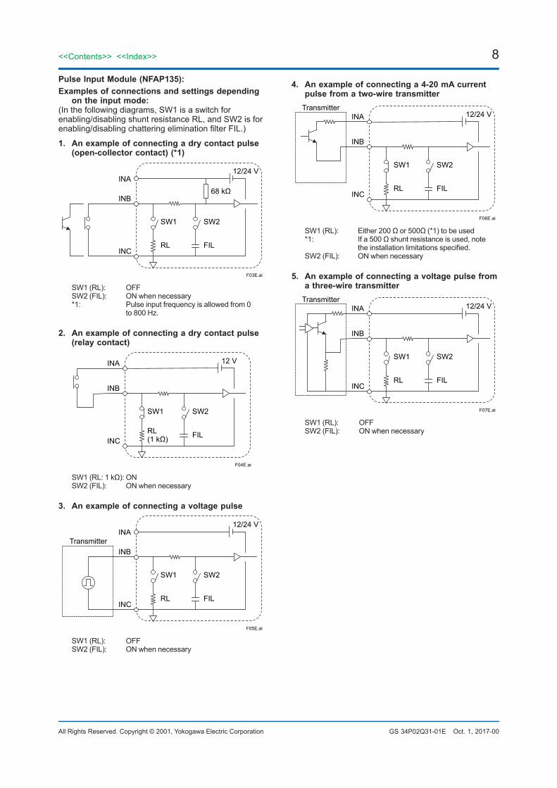
4. An example of connecting a 4-20 mA current pulse from a two-wire transmitter
INA
INB
INCRL FIL
SW2SW1
12/24 V
F06E.ai
Transmitter
SW1 (RL): Either 200 Ω or 500Ω (*1) to be used*1: If a 500 Ω shunt resistance is used, note
the installation limitations specified.SW2 (FIL): ON when necessary
5. An example of connecting a voltage pulse from a three-wire transmitter
INA
INB
INCRL FIL
SW2SW1
12/24 V
F07E.ai
Transmitter
SW1 (RL): OFFSW2 (FIL): ON when necessary
Pulse Input Module (NFAP135):Examples of connections and settings depending
on the input mode:(In the following diagrams, SW1 is a switch for enabling/disabling shunt resistance RL, and SW2 is for enabling/disabling chattering elimination filter FIL.)
1. An example of connecting a dry contact pulse (open-collector contact) (*1)
INA
INB
INCRL FIL
SW2SW1
68 kΩ
12/24 V
F03E.ai
SW1 (RL): OFFSW2 (FIL): ON when necessary*1: Pulse input frequency is allowed from 0 to 800 Hz.
2. An example of connecting a dry contact pulse (relay contact)
INA
INB
INCRL(1 kΩ) FIL
SW2SW1
12 V
F04E.ai
SW1 (RL: 1 kΩ): ONSW2 (FIL): ON when necessary
3. An example of connecting a voltage pulse
INA
INBTransmitter
INCRL FIL
SW2SW1
12/24 V
F05E.ai
SW1 (RL): OFFSW2 (FIL): ON when necessary
Oct. 1, 2017-00
9<<Contents>> <<Index>>
All Rights Reserved. Copyright © 2001, Yokogawa Electric Corporation GS 34P02Q31-01E Oct. 1, 2017-00
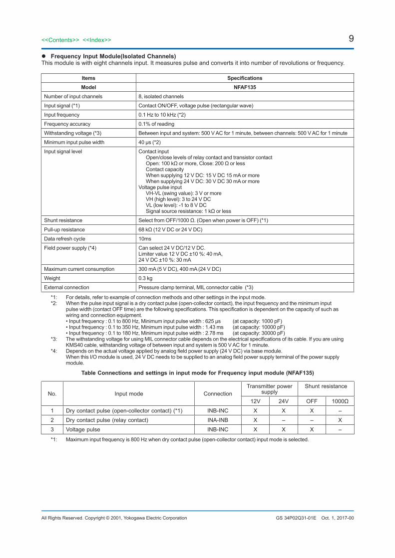
l Frequency Input Module(Isolated Channels)This module is with eight channels input. It measures pulse and converts it into number of revolutions or frequency.
Items SpecificationsModel NFAF135
Number of input channels 8, isolated channels
Input signal (*1) Contact ON/OFF, voltage pulse (rectangular wave)
Input frequency 0.1 Hz to 10 kHz (*2)
Frequency accuracy 0.1% of reading
Withstanding voltage (*3) Between input and system: 500 V AC for 1 minute, between channels: 500 V AC for 1 minute
Minimum input pulse width 40 μs (*2)
Input signal level Contact input Open/close levels of relay contact and transistor contact Open: 100 kΩ or more, Close: 200 Ω or less Contact capacity When supplying 12 V DC: 15 V DC 15 mA or more When supplying 24 V DC: 30 V DC 30 mA or moreVoltage pulse input VH-VL (swing value): 3 V or more VH (high level): 3 to 24 V DC VL (low level): -1 to 8 V DC Signal source resistance: 1 kΩ or less
Shunt resistance Select from OFF/1000 Ω. (Open when power is OFF) (*1)
Pull-up resistance 68 kΩ (12 V DC or 24 V DC)
Data refresh cycle 10ms
Field power supply (*4) Can select 24 V DC/12 V DC.Limiter value 12 V DC ±10 %: 40 mA,24 V DC ±10 %: 30 mA
Maximum current consumption 300 mA (5 V DC), 400 mA (24 V DC)
Weight 0.3 kg
External connection Pressure clamp terminal, MIL connector cable (*3)
*1: For details, refer to example of connection methods and other settings in the input mode.*2: When the pulse input signal is a dry contact pulse (open-collector contact), the input frequency and the minimum input
pulse width (contact OFF time) are the following specifications. This specification is dependent on the capacity of such as wiring and connection equipment.
• Input frequency : 0.1 to 800 Hz, Minimum input pulse width : 625 μs (at capacity: 1000 pF) • Input frequency : 0.1 to 350 Hz, Minimum input pulse width : 1.43 ms (at capacity: 10000 pF) • Input frequency : 0.1 to 180 Hz, Minimum input pulse width : 2.78 ms (at capacity: 30000 pF)*3: The withstanding voltage for using MIL connector cable depends on the electrical specifications of its cable. If you are using
KMS40 cable, withstanding voltage of between input and system is 500 V AC for 1 minute.*4: Depends on the actual voltage applied by analog field power supply (24 V DC) via base module. When this I/O module is used, 24 V DC needs to be supplied to an analog field power supply terminal of the power supply
module.
Table Connections and settings in input mode for Frequency input module (NFAF135)
No. Input mode ConnectionTransmitter power
supplyShunt resistance
12V 24V OFF 1000Ω
1 Dry contact pulse (open-collector contact) (*1) INB-INC X X X –
2 Dry contact pulse (relay contact) INA-INB X – – X
3 Voltage pulse INB-INC X X X –
*1: Maximum input frequency is 800 Hz when dry contact pulse (open-collector contact) input mode is selected.

10
All Rights Reserved. Copyright © 2001, Yokogawa Electric Corporation
<<Contents>> <<Index>>
GS 34P02Q31-01E
Frequency Input Module (NFAF135):Examples of connections and settings depending on the input mode:(In the following diagrams, SW1 is a switch for enabling/disabling shunt resistance RL.)
Oct. 1, 2017-00
1. An example of connecting a dry contact pulse (open-collector contact)
INA
INB
INCRL
SW1
68 kΩ
12/24 V
F08E.ai
SW1 (RL): OFF
2. An example of connecting a dry contact pulse (relay contact)
INA
INB
INCRL(1 kΩ)
SW1
12 V
F09E.ai
SW1 (RL: 1 kΩ): ON
3. An example of connecting a voltage pulse
INA
INB
INCRL
SW1
12/24 V
F10E.ai
SW1 (RL): OFF
11<<Contents>> <<Index>>
All Rights Reserved. Copyright © 2001, Yokogawa Electric Corporation GS 34P02Q31-01E Oct. 1, 2017-00
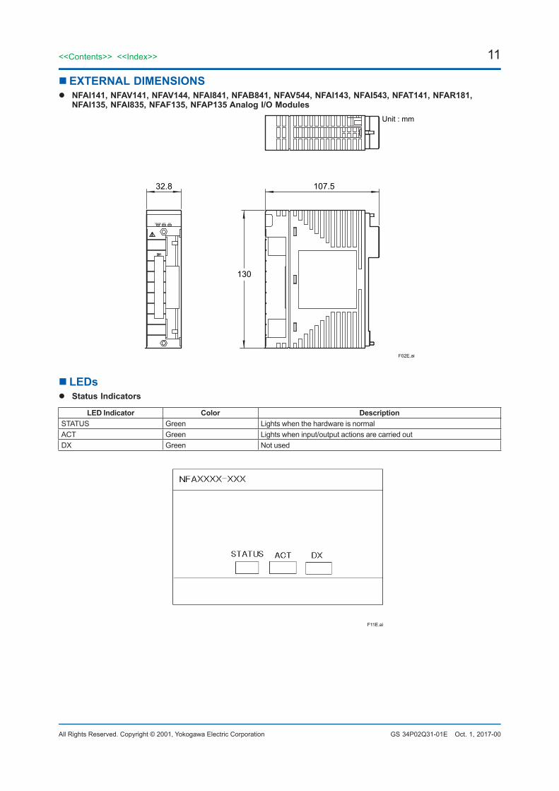
n EXTERNAL DIMENSIONSl NFAI141, NFAV141, NFAV144, NFAI841, NFAB841, NFAV544, NFAI143, NFAI543, NFAT141, NFAR181,
NFAI135, NFAI835, NFAF135, NFAP135 Analog I/O Modules
107.532.8
130
Unit : mm
F02E.ai
n LEDsl Status Indicators
LED Indicator Color Description STATUS Green Lights when the hardware is normal ACT Green Lights when input/output actions are carried out DX Green Not used
F11E.ai
12
All Rights Reserved. Copyright © 2001, Yokogawa Electric Corporation
<<Contents>> <<Index>>
GS 34P02Q31-01E Oct. 1, 2017-00
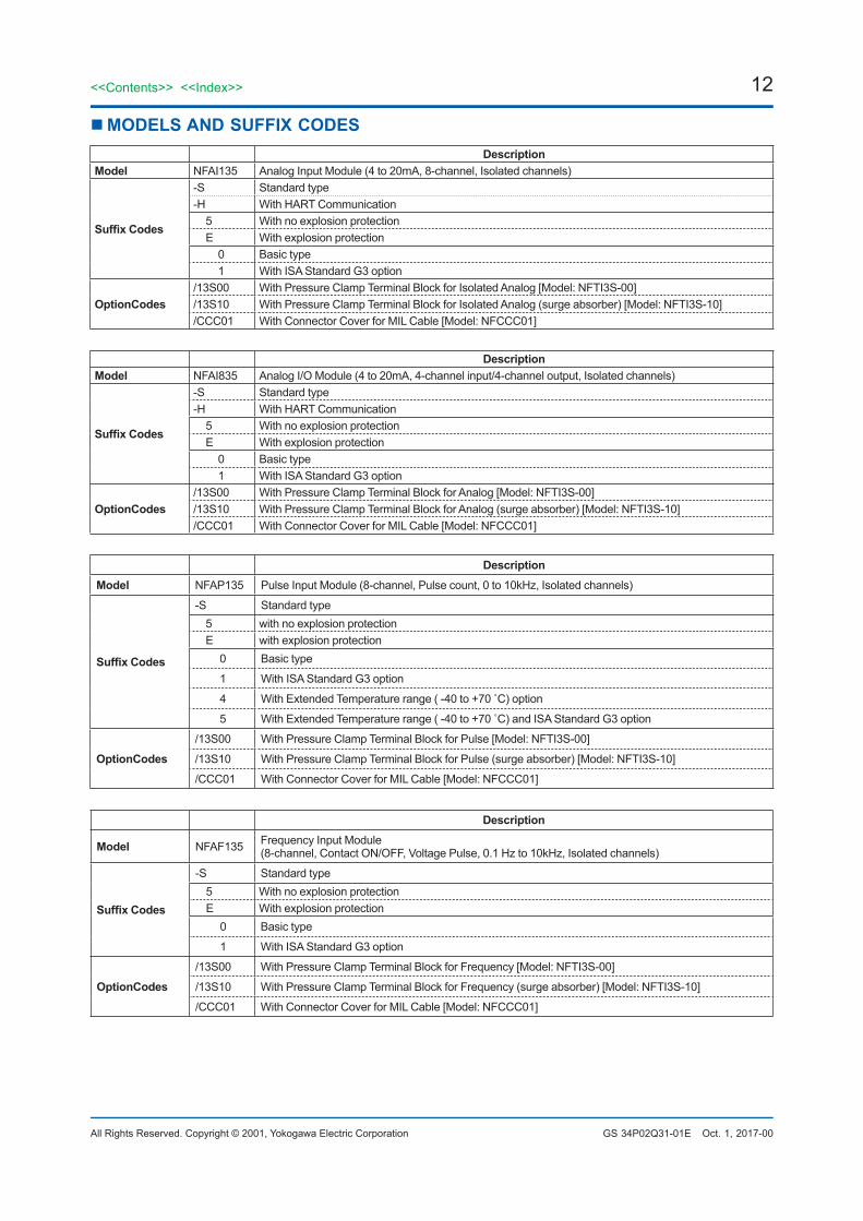
nMODELS AND SUFFIX CODESDescription
Model NFAI135 Analog Input Module (4 to 20mA, 8-channel, Isolated channels)
Suffix Codes
-S Standard type -H With HART Communication 5 With no explosion protection E With explosion protection 0 Basic type 1 With ISA Standard G3 option
OptionCodes /13S00 With Pressure Clamp Terminal Block for Isolated Analog [Model: NFTI3S-00] /13S10 With Pressure Clamp Terminal Block for Isolated Analog (surge absorber) [Model: NFTI3S-10]/CCC01 With Connector Cover for MIL Cable [Model: NFCCC01]
Description Model NFAI835 Analog I/O Module (4 to 20mA, 4-channel input/4-channel output, Isolated channels)
Suffix Codes
-S Standard type -H With HART Communication 5 With no explosion protection E With explosion protection 0 Basic type 1 With ISA Standard G3 option
OptionCodes /13S00 With Pressure Clamp Terminal Block for Analog [Model: NFTI3S-00] /13S10 With Pressure Clamp Terminal Block for Analog (surge absorber) [Model: NFTI3S-10]/CCC01 With Connector Cover for MIL Cable [Model: NFCCC01]
Description Model NFAP135 Pulse Input Module (8-channel, Pulse count, 0 to 10kHz, Isolated channels)
Suffix Codes
-S Standard type 5 with no explosion protection E with explosion protection 0 Basic type
1 With ISA Standard G3 option
4 With Extended Temperature range ( -40 to +70 ̊ C) option
5 With Extended Temperature range ( -40 to +70 ̊ C) and ISA Standard G3 option
OptionCodes /13S00 With Pressure Clamp Terminal Block for Pulse [Model: NFTI3S-00]
/13S10 With Pressure Clamp Terminal Block for Pulse (surge absorber) [Model: NFTI3S-10]
/CCC01 With Connector Cover for MIL Cable [Model: NFCCC01]
Description
Model NFAF135 Frequency Input Module (8-channel, Contact ON/OFF, Voltage Pulse, 0.1 Hz to 10kHz, Isolated channels)
Suffix Codes
-S Standard type 5 With no explosion protection E With explosion protection 0 Basic type
1 With ISA Standard G3 option
OptionCodes /13S00 With Pressure Clamp Terminal Block for Frequency [Model: NFTI3S-00]
/13S10 With Pressure Clamp Terminal Block for Frequency (surge absorber) [Model: NFTI3S-10]
/CCC01 With Connector Cover for MIL Cable [Model: NFCCC01]
13<<Contents>> <<Index>>
All Rights Reserved. Copyright © 2001, Yokogawa Electric Corporation GS 34P02Q31-01E Oct. 1, 2017-00
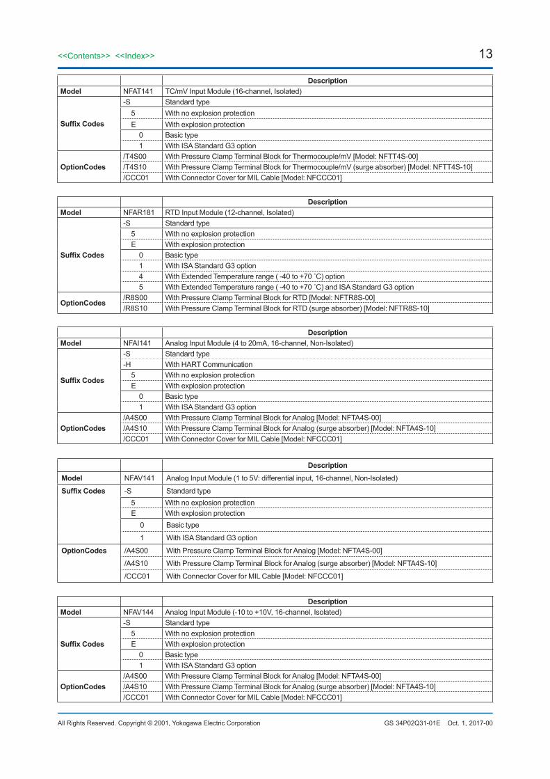
Description Model NFAT141 TC/mV Input Module (16-channel, Isolated)
Suffix Codes
-S Standard type 5 With no explosion protection E With explosion protection 0 Basic type 1 With ISA Standard G3 option
OptionCodes /T4S00 With Pressure Clamp Terminal Block for Thermocouple/mV [Model: NFTT4S-00] /T4S10 With Pressure Clamp Terminal Block for Thermocouple/mV (surge absorber) [Model: NFTT4S-10]/CCC01 With Connector Cover for MIL Cable [Model: NFCCC01]
Description Model NFAR181 RTD Input Module (12-channel, Isolated)
Suffix Codes
-S Standard type 5 With no explosion protection E With explosion protection 0 Basic type 1 With ISA Standard G3 option 4 With Extended Temperature range ( -40 to +70 ̊ C) option 5 With Extended Temperature range ( -40 to +70 ̊ C) and ISA Standard G3 option
OptionCodes /R8S00 With Pressure Clamp Terminal Block for RTD [Model: NFTR8S-00] /R8S10 With Pressure Clamp Terminal Block for RTD (surge absorber) [Model: NFTR8S-10]
Description Model NFAI141 Analog Input Module (4 to 20mA, 16-channel, Non-Isolated)
Suffix Codes
-S Standard type -H With HART Communication 5 With no explosion protection E With explosion protection 0 Basic type 1 With ISA Standard G3 option
OptionCodes /A4S00 With Pressure Clamp Terminal Block for Analog [Model: NFTA4S-00] /A4S10 With Pressure Clamp Terminal Block for Analog (surge absorber) [Model: NFTA4S-10]/CCC01 With Connector Cover for MIL Cable [Model: NFCCC01]
Description Model NFAV141 Analog Input Module (1 to 5V: differential input, 16-channel, Non-Isolated)
Suffix Codes -S Standard type 5 With no explosion protection E With explosion protection 0 Basic type
1 With ISA Standard G3 option
OptionCodes /A4S00 With Pressure Clamp Terminal Block for Analog [Model: NFTA4S-00]
/A4S10 With Pressure Clamp Terminal Block for Analog (surge absorber) [Model: NFTA4S-10]
/CCC01 With Connector Cover for MIL Cable [Model: NFCCC01]
Description Model NFAV144 Analog Input Module (-10 to +10V, 16-channel, Isolated)
Suffix Codes
-S Standard type 5 With no explosion protection E With explosion protection 0 Basic type 1 With ISA Standard G3 option
OptionCodes /A4S00 With Pressure Clamp Terminal Block for Analog [Model: NFTA4S-00] /A4S10 With Pressure Clamp Terminal Block for Analog (surge absorber) [Model: NFTA4S-10]/CCC01 With Connector Cover for MIL Cable [Model: NFCCC01]
14
All Rights Reserved. Copyright © 2001, Yokogawa Electric Corporation
<<Contents>> <<Index>>
GS 34P02Q31-01E Oct. 1, 2017-00
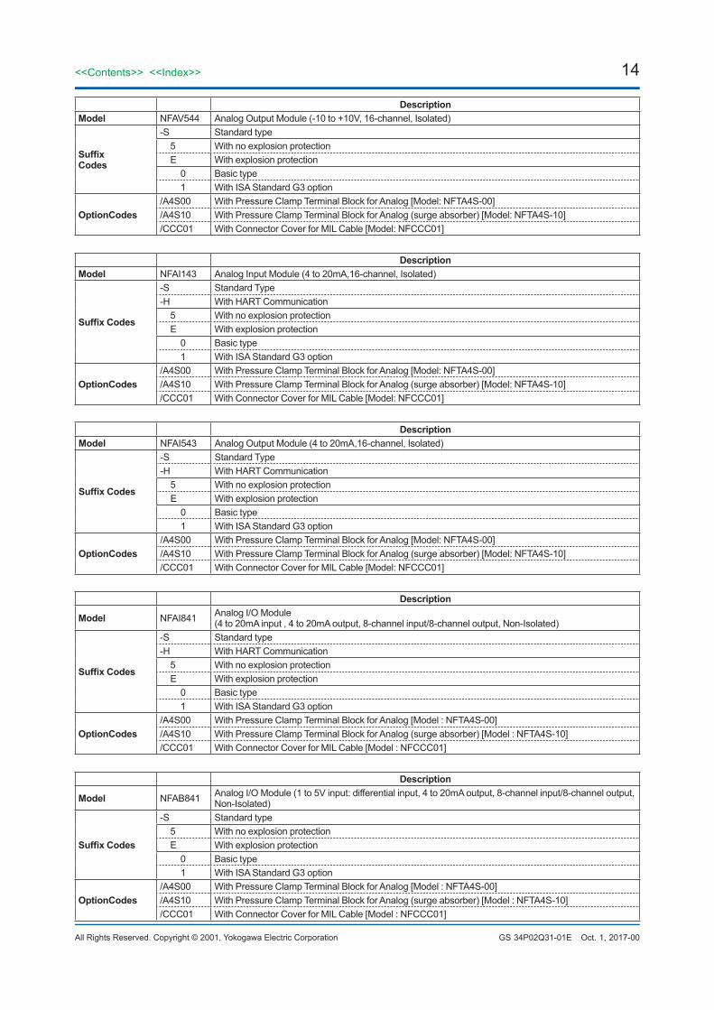
Description Model NFAV544 Analog Output Module (-10 to +10V, 16-channel, Isolated)
Suffix Codes
-S Standard type 5 With no explosion protection E With explosion protection 0 Basic type 1 With ISA Standard G3 option
OptionCodes /A4S00 With Pressure Clamp Terminal Block for Analog [Model: NFTA4S-00] /A4S10 With Pressure Clamp Terminal Block for Analog (surge absorber) [Model: NFTA4S-10]/CCC01 With Connector Cover for MIL Cable [Model: NFCCC01]
Description Model NFAI143 Analog Input Module (4 to 20mA,16-channel, Isolated)
Suffix Codes
-S Standard Type -H With HART Communication 5 With no explosion protection E With explosion protection 0 Basic type 1 With ISA Standard G3 option
OptionCodes /A4S00 With Pressure Clamp Terminal Block for Analog [Model: NFTA4S-00] /A4S10 With Pressure Clamp Terminal Block for Analog (surge absorber) [Model: NFTA4S-10]/CCC01 With Connector Cover for MIL Cable [Model: NFCCC01]
Description Model NFAI543 Analog Output Module (4 to 20mA,16-channel, Isolated)
Suffix Codes
-S Standard Type -H With HART Communication 5 With no explosion protection E With explosion protection 0 Basic type 1 With ISA Standard G3 option
OptionCodes /A4S00 With Pressure Clamp Terminal Block for Analog [Model: NFTA4S-00] /A4S10 With Pressure Clamp Terminal Block for Analog (surge absorber) [Model: NFTA4S-10]/CCC01 With Connector Cover for MIL Cable [Model: NFCCC01]
Description
Model NFAI841 Analog I/O Module (4 to 20mA input , 4 to 20mA output, 8-channel input/8-channel output, Non-Isolated)
Suffix Codes
-S Standard type -H With HART Communication 5 With no explosion protection E With explosion protection 0 Basic type 1 With ISA Standard G3 option
OptionCodes /A4S00 With Pressure Clamp Terminal Block for Analog [Model : NFTA4S-00] /A4S10 With Pressure Clamp Terminal Block for Analog (surge absorber) [Model : NFTA4S-10]/CCC01 With Connector Cover for MIL Cable [Model : NFCCC01]
Description
Model NFAB841 Analog I/O Module (1 to 5V input: differential input, 4 to 20mA output, 8-channel input/8-channel output, Non-Isolated)
Suffix Codes
-S Standard type 5 With no explosion protection E With explosion protection 0 Basic type 1 With ISA Standard G3 option
OptionCodes /A4S00 With Pressure Clamp Terminal Block for Analog [Model : NFTA4S-00] /A4S10 With Pressure Clamp Terminal Block for Analog (surge absorber) [Model : NFTA4S-10]/CCC01 With Connector Cover for MIL Cable [Model : NFCCC01]
15<<Contents>> <<Index>>
All Rights Reserved. Copyright © 2001, Yokogawa Electric Corporation GS 34P02Q31-01E Oct. 1, 2017-00
n RESTRICTIONS AND PRECAUTIONS ON INSTALLATIONSee Installation Guide for “STARDOM FCN/FCJ Installation Guide” (TI 34P02Q91-01E).
lLimitations of Installation for NFAT141 (the combination of Thermocouple input and Pressure clamp terminal)
To keep the reference junction compensation accuracy, make sure to meet the following conditions. The pressure clamp terminal should not be affected by radiated heat. • Do not install a heat-radiating unit beneath the NFAT141 installed unit.• Do not install NFAT141 in the place where airflow affects directly.• Do not install NFAT141 next to the CPU modules (NFCP501/NFCP502), power supply modules (NFPW44x).• The installable modules next to the NFAT141 are as follows. When installing other than following I/O modules,
make an empty slot (one or more) in each side. Installable modules: NFAT141, NFAR181, NFAV141, NFAV144
lLimitations of Installation for I/O Modules When you install the following I/O modules, ensure that the required power volume does not exceed the rated power
output of the power supply module. For the amount of power supply that each I/O module requires (5 V DC and 24 V DC), refer to the applicable general specifications.
• The following modules need to be checked for current consumption from a 5 V DC system power supply NFAV544, NFDV551, NFDV561 and NFDR541• The following modules need to be checked for current consumption from a 24 V DC analog field power supply NFAI841, NFAI143 and NFAI543
nORDERING INFORMATIONSpecify models and suffix codes. For selecting the right products for explosion protection, please refer to “STARDOM FCN/FCJ Installation Guide” (TI 34P02Q91-01E) without fail.
nTRADEMARK• STARDOM is a trademark of Yokogawa Electric Corporation.• Other company names and product names in this document are registered trademarks or trademarks of their
respective holders.
Subject to change without notice.