general-purpose ac servo - kavram mühendislik · general-purpose ac servo melservo-je servo...
TRANSCRIPT
SH (NA) 030166-B (1503) MEE Printed in Japan Specifications are subject to change without notice.This Instruction Manual uses recycled paper.
MODEL
MODELCODE
General-Purpose AC Servo
ME
LS
ER
VO
-JE S
ervo am
plifier IN
ST
RU
CT
ION
MA
NU
AL
(TR
OU
BL
E S
HO
OT
ING
)
HEAD OFFICE : TOKYO BLDG MARUNOUCHI TOKYO 100-8310
MELSERVO-JE Servo amplifierINSTRUCTION MANUAL (TROUBLE SHOOTING)
1CW710
MR-JE INSTRUCTIONMANUAL(TROUBLESHOOTING)
BB
A - 1
Safety Instructions Please read the instructions carefully before using the equipment.
To use the equipment correctly, do not attempt to install, operate, maintain, or inspect the equipment until you have read through this Instruction Manual, Installation guide, and appended documents carefully. Do not use the equipment until you have a full knowledge of the equipment, safety information and instructions.
In this Instruction Manual, the safety instruction levels are classified into "WARNING" and "CAUTION".
WARNING Indicates that incorrect handling may cause hazardous conditions, resulting in death or severe injury.
CAUTION Indicates that incorrect handling may cause hazardous conditions, resulting in medium or slight injury to personnel or may cause physical damage.
Note that the CAUTION level may lead to a serious consequence according to conditions.
Please follow the instructions of both levels because they are important to personnel safety.
What must not be done and what must be done are indicated by the following diagrammatic symbols.
Indicates what must not be done. For example, "No Fire" is indicated by .
Indicates what must be done. For example, grounding is indicated by .
In this Instruction Manual, instructions at a level lower than the above, instructions for other functions, and so on are classified into "POINT". After reading this Instruction Manual, keep it accessible to the operator.
www.kavrammuhendislik.com.tr
A - 2
1. To prevent electric shock, note the following.
WARNING Before wiring and inspections, turn off the power and wait for 15 minutes or more until the charge lamp turns off. Otherwise, an electric shock may occur. In addition, always confirm that the charge lamp is off
from the front of the servo amplifier.
Do not operate switches with wet hands. Doing so may cause an electric shock.
2. To prevent injury, note the following.
CAUTION The servo amplifier heat sink, regenerative resistor, servo motor, etc. may be hot while the power is on, or for some time after power-off. Take safety measures, such as providing covers, to avoid accidentally
touching the parts (cables, etc.) by hand.
3. Additional instructions The following instructions should also be fully noted. Incorrect handling may cause a malfunction, injury,
electric shock, etc.
(1) Wiring
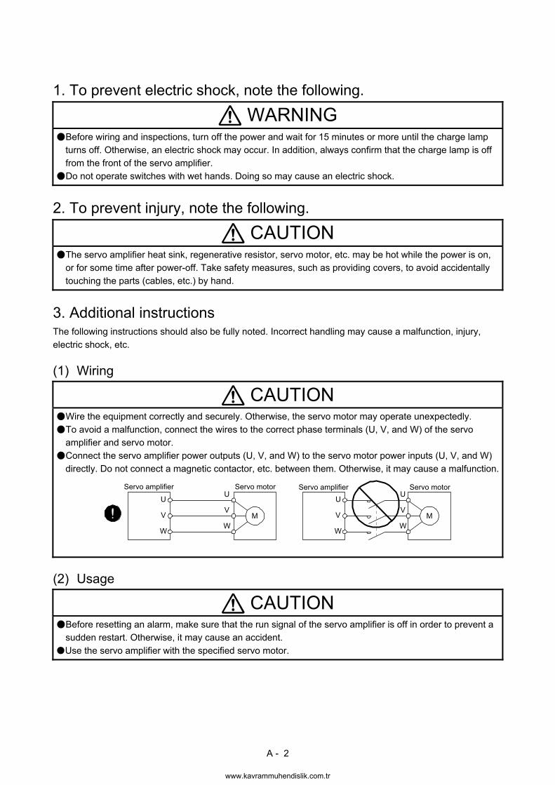
CAUTION Wire the equipment correctly and securely. Otherwise, the servo motor may operate unexpectedly.
To avoid a malfunction, connect the wires to the correct phase terminals (U, V, and W) of the servo amplifier and servo motor.
Connect the servo amplifier power outputs (U, V, and W) to the servo motor power inputs (U, V, and W)
directly. Do not connect a magnetic contactor, etc. between them. Otherwise, it may cause a malfunction.
U
Servo motor
MV
W
U
V
W
U
MV
W
U
V
W
Servo amplifier Servo motorServo amplifier
(2) Usage
CAUTION Before resetting an alarm, make sure that the run signal of the servo amplifier is off in order to prevent a sudden restart. Otherwise, it may cause an accident.
Use the servo amplifier with the specified servo motor.
www.kavrammuhendislik.com.tr
A - 3
(3) Corrective actions
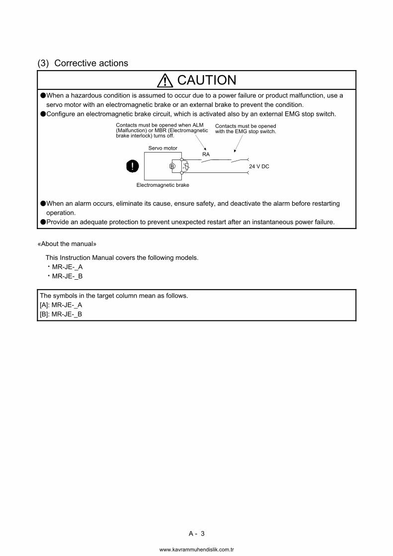
CAUTION When a hazardous condition is assumed to occur due to a power failure or product malfunction, use a
servo motor with an electromagnetic brake or an external brake to prevent the condition.
Configure an electromagnetic brake circuit, which is activated also by an external EMG stop switch.
Servo motor
Electromagnetic brake
B
RA
Contacts must be openedwith the EMG stop switch.
Contacts must be opened when ALM(Malfunction) or MBR (Electromagneticbrake interlock) turns off.
24 V DC
When an alarm occurs, eliminate its cause, ensure safety, and deactivate the alarm before restarting
operation.
Provide an adequate protection to prevent unexpected restart after an instantaneous power failure.
«About the manual»
This Instruction Manual covers the following models.
MR-JE-_A
MR-JE-_B
The symbols in the target column mean as follows.
[A]: MR-JE-_A [B]: MR-JE-_B
www.kavrammuhendislik.com.tr

A - 4
MEMO
www.kavrammuhendislik.com.tr
1
CONTENTS
1. SERVO AMPLIFIER TROUBLESHOOTING 1- 1 to 1-58
1.1 Explanations of the lists .................................................................................................................... 1- 1 1.2 Alarm list ........................................................................................................................................... 1- 2 1.3 Warning list ....................................................................................................................................... 1- 6 1.4 Remedies for alarms ......................................................................................................................... 1- 8 1.5 Remedies for warnings .................................................................................................................... 1-37 1.6 Trouble which does not trigger an alarm/warning ........................................................................... 1-48
2. DRIVE RECORDER 2- 1 to 2- 6
2.1 How to use the drive recorder ........................................................................................................... 2- 1 2.2 How to display drive recorder information ........................................................................................ 2- 6
APPENDIX App. - 1 to App. - 1
App. 1 Detection points of [AL. 25], [AL. 92], and [AL. 9F] ............................................................... App.- 1
www.kavrammuhendislik.com.tr
2
MEMO
www.kavrammuhendislik.com.tr

1. SERVO AMPLIFIER TROUBLESHOOTING
1 - 1
1. SERVO AMPLIFIER TROUBLESHOOTING
POINT
As soon as an alarm occurs, turn SON (Servo-on) off and interrupt the power.
[AL. 37 Parameter error] and warnings (except [AL. F0 Tough drive warning]) are not recorded in the alarm history.
When an error occurs during operation, the corresponding alarm or warning is displayed. If an alarm is displayed, refer to section 1.4 and take the appropriate action. When an alarm occurs, ALM (Malfunction) turns off. If any warning occurs, refer to section 1.5 and take the appropriate action. 1.1 Explanations of the lists
(1) No./Name/Detail No./Detail name Indicates the No./name/detail No./detail name of alarms or warnings.
(2) Stop method
For the alarms and warnings in which "SD" is written in the stop method column, the servo motor stops with the dynamic brake after forced stop deceleration. For the alarms and warnings in which "DB" or "EDB" is written in the stop method column, the servo motor stops with the dynamic brake without forced stop deceleration.
(3) Alarm deactivation
After the alarm cause has been removed, the alarm can be deactivated in any of the methods marked in the alarm deactivation column. Warnings are automatically canceled after the cause of occurrence is removed. Alarms are deactivated by alarm reset, CPU reset, or power cycling.
(a) MR-JE-_A
Alarm deactivation Explanation
Alarm reset 1. Turn on RES (Reset) with an input device. 2. Push the "SET" button while the display of the servo amplifier is in the current
alarm display mode. 3. Click the "Occurring Alarm Reset" button in the "Alarm Display" window of MR
Configurator2.
Power cycling Turn off the power, check that the 5-digit, 7-segment LED display is off, and then turn on the power.
(b) MR-JE-_B
Alarm deactivation Explanation
Alarm reset 1. Error reset command from the controller 2. Click the "Occurring Alarm Reset" button in the "Alarm Display" window of MR
Configurator2.
CPU reset Reset the controller itself.
Power cycling Turn off the power, check that the 3-digit, 7-segment LED display is off, and then turn on the power.
(4) Alarm code
Alarm codes are outputted only from the MR-JE-_A. To output alarm codes, set [Pr. PD34] to "_ _ _ 1" when using an MR-JE-_A. Alarm codes are outputted by turning on/off bit 0 to bit 2. Warnings ([AL. 90] to [AL. F3]) do not have alarm codes. The alarm codes in the following table are outputted when they occur. The alarm codes are not outputted in normal condition.
www.kavrammuhendislik.com.tr
1. SERVO AMPLIFIER TROUBLESHOOTING
1 - 2
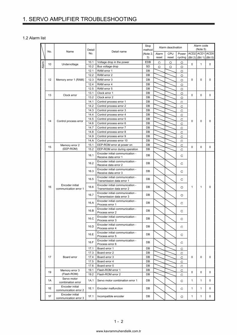
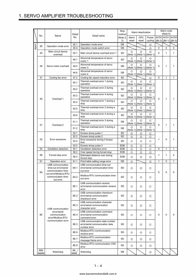
1.2 Alarm list
No. Name Detail No.
Detail name
Stop
method
(Note 2, 3)
Alarm deactivation Alarm code
(Note 5)
Alarm reset
CPU reset
Power cycling
ACD2
(Bit 2)
ACD1
(Bit 1)
ACD0
(Bit 0)
Ala
rm
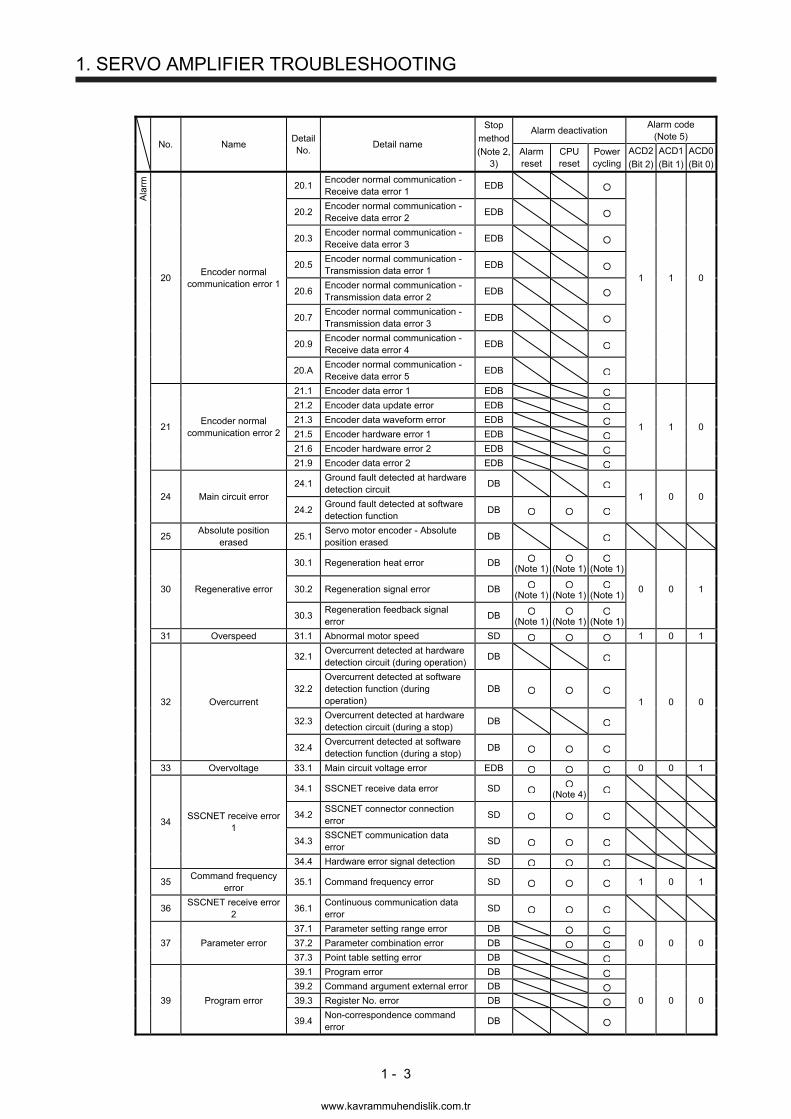
10 Undervoltage 10.1 Voltage drop in the power EDB
0 1 0 10.2 Bus voltage drop SD
12.1 RAM error 1 DB
12.2 RAM error 2 DB
12 Memory error 1 (RAM) 12.3 RAM error 3 DB 0 0 0
12.4 RAM error 4 DB
12.5 RAM error 5 DB
13 Clock error
13.1 Clock error 1 DB 0 0 0
13.2 Clock error 2 DB
14.1 Control process error 1 DB
14.2 Control process error 2 DB
14.3 Control process error 3 DB
14.4 Control process error 4 DB
14 Control process error
14.5 Control process error 5 DB 0 0 0
14.6 Control process error 6 DB
14.7 Control process error 7 DB
14.8 Control process error 8 DB
14.9 Control process error 9 DB
14.A Control process error 10 DB
15
Memory error 2 (EEP-ROM)
15.1 EEP-ROM error at power on DB 0 0 0
15.2 EEP-ROM error during operation DB
16.1
Encoder initial communication - Receive data error 1
DB
16.2
Encoder initial communication - Receive data error 2
DB
16.3
Encoder initial communication - Receive data error 3
DB
16.5
Encoder initial communication - Transmission data error 1
DB
16
Encoder initial communication error 1
16.6 Encoder initial communication - Transmission data error 2
DB 1 1 0
16.7
Encoder initial communication - Transmission data error 3
DB
16.A
Encoder initial communication - Process error 1
DB
16.B
Encoder initial communication - Process error 2
DB
16.C
Encoder initial communication - Process error 3
DB
16.D
Encoder initial communication - Process error 4
DB
16.E
Encoder initial communication - Process error 5
DB
16.F
Encoder initial communication - Process error 6
DB
17 Board error
17.1 Board error 1 DB
0 0 0
17.3 Board error 2 DB
17.4 Board error 3 DB
17.5 Board error 4 DB
17.6 Board error 5 DB
19
Memory error 3 (Flash-ROM)
19.1 Flash-ROM error 1 DB 0 0 0
19.2 Flash-ROM error 2 DB
1A
Servo motor combination error
1A.1 Servo motor combination error 1 DB 1 1 0
1E
Encoder initial communication error 2
1E.1 Encoder malfunction DB 1 1 0
1F
Encoder initial communication error 3
1F.1 Incompatible encoder DB 1 1 0
www.kavrammuhendislik.com.tr
1. SERVO AMPLIFIER TROUBLESHOOTING
1 - 3
No. Name Detail No.
Detail name
Stop
method
(Note 2, 3)
Alarm deactivation Alarm code
(Note 5)
Alarm reset
CPU reset
Power cycling
ACD2
(Bit 2)
ACD1
(Bit 1)
ACD0
(Bit 0)
Ala
rm
20.1 Encoder normal communication - Receive data error 1
EDB
20.2 Encoder normal communication - Receive data error 2
EDB
20.3 Encoder normal communication - Receive data error 3
EDB
20 Encoder normal
communication error 1
20.5 Encoder normal communication - Transmission data error 1
EDB 1 1 0
20.6 Encoder normal communication - Transmission data error 2
EDB
20.7
Encoder normal communication - Transmission data error 3
EDB
20.9
Encoder normal communication - Receive data error 4
EDB
20.A
Encoder normal communication - Receive data error 5
EDB
21 Encoder normal
communication error 2
21.1 Encoder data error 1 EDB
1 1 0
21.2 Encoder data update error EDB
21.3 Encoder data waveform error EDB
21.5 Encoder hardware error 1 EDB
21.6 Encoder hardware error 2 EDB
21.9 Encoder data error 2 EDB
24 Main circuit error
24.1 Ground fault detected at hardware detection circuit
DB 1 0 0
24.2
Ground fault detected at software detection function
DB
25
Absolute position erased
25.1 Servo motor encoder - Absolute position erased
DB
30.1 Regeneration heat error DB
(Note 1)
(Note 1)
(Note 1)
30 Regenerative error 30.2 Regeneration signal error DB
(Note 1)
(Note 1)
(Note 1) 0 0 1
30.3
Regeneration feedback signal error
DB (Note 1)
(Note 1)
(Note 1)
31 Overspeed 31.1 Abnormal motor speed SD 1 0 1
32.1
Overcurrent detected at hardware detection circuit (during operation)
DB
32 Overcurrent
32.2 Overcurrent detected at software detection function (during operation)
DB 1 0 0
32.3
Overcurrent detected at hardware detection circuit (during a stop)
DB
32.4
Overcurrent detected at software detection function (during a stop)
DB
33 Overvoltage 33.1 Main circuit voltage error EDB 0 0 1
34 SSCNET receive error
1
34.1 SSCNET receive data error SD
(Note 4)
34.2
SSCNET connector connection error
SD
34.3
SSCNET communication data error
SD
34.4 Hardware error signal detection SD
35
Command frequency error
35.1 Command frequency error SD 1 0 1
36
SSCNET receive error 2
36.1 Continuous communication data error
SD
37.1 Parameter setting range error DB
37 Parameter error 37.2 Parameter combination error DB 0 0 0
37.3 Point table setting error DB
39.1 Program error DB
39.2 Command argument external error DB
39 Program error 39.3 Register No. error DB 0 0 0
39.4
Non-correspondence command error
DB
www.kavrammuhendislik.com.tr
1. SERVO AMPLIFIER TROUBLESHOOTING
1 - 4
No. Name Detail No.
Detail name
Stop
method
(Note 2, 3)
Alarm deactivation Alarm code
(Note 5)
Alarm reset
CPU reset
Power cycling
ACD2
(Bit 2)
ACD1
(Bit 1)
ACD0
(Bit 0)
Ala
rm
3E Operation mode error 3E.1 Operation mode error DB
3E.6 Operation mode switch error DB 0 0 0
45 Main circuit device
overheat 45.1 Main circuit device overheat error 1 SD
(Note 1)
(Note 1)
(Note 1) 0 1 1
46 Servo motor overheat
46.1 Abnormal temperature of servo motor 1
SD (Note 1)
(Note 1)
(Note 1)
0 1 1 46.5 Abnormal temperature of servo motor 3
DB (Note 1)
(Note 1)
(Note 1)
46.6 Abnormal temperature of servo motor 4
DB (Note 1)
(Note 1)
(Note 1)
47 Cooling fan error 47.2 Cooling fan speed reduction error SD 0 1 1
50.1
Thermal overload error 1 during operation
SD (Note 1)
(Note 1)
(Note 1)
50.2 Thermal overload error 2 during operation
SD (Note 1)
(Note 1)
(Note 1)
50 Overload 1
50.3 Thermal overload error 4 during operation
SD (Note 1)
(Note 1)
(Note 1)
0 1 1
50.4 Thermal overload error 1 during a stop
SD (Note 1)
(Note 1)
(Note 1)
50.5 Thermal overload error 2 during a stop
SD (Note 1)
(Note 1)
(Note 1)
50.6 Thermal overload error 4 during a stop
SD (Note 1)
(Note 1)
(Note 1)
51 Overload 2
51.1 Thermal overload error 3 during operation
DB (Note 1)
(Note 1)
(Note 1)
0 1 1
51.2 Thermal overload error 3 during a stop
DB (Note 1)
(Note 1)
(Note 1)
52.1 Excess droop pulse 1 SD
52 Error excessive
52.3 Excess droop pulse 2 SD 1 0 1
52.4 Error excessive during 0 torque limit
SD
52.5 Excess droop pulse 3 EDB
54 Oscillation detection 54.1 Oscillation detection error EDB 0 1 1
56 Forced stop error
56.2 Over speed during forced stop EDB 1 1 0
56.3 Estimated distance over during forced stop
EDB
61 Operation error 61.1 Point table setting range error DB 1 0 1
8A
USB communication time-out error/serial communication time-
out error/Modbus-RTU communication time-
out error
8A.1 USB communication time-out error/serial communication time-out error
SD
0 0 0
8A.2 Modbus-RTU communication time-out error
SD
8E.1
USB communication receive error/serial communication receive error
SD
8E.2
USB communication checksum error/serial communication checksum error
SD
USB communication error/serial
communication error/Modbus-RTU
communication error
8E.3 USB communication character error/serial communication character error
SD
8E 8E.4
USB communication command error/serial communication command error
SD 0 0 0
8E.5
USB communication data number error/serial communication data number error
SD
8E.6
Modbus-RTU communication receive error
SD
8E.7
Modbus-RTU communication message frame error
SD
8E.8
Modbus-RTU communication CRC error
SD
888/ 88888
Watchdog 88._/
8888._ Watchdog DB
www.kavrammuhendislik.com.tr
1. SERVO AMPLIFIER TROUBLESHOOTING
1 - 5
Note 1. Remove the cause of occurrence, and then allow about 30 minutes for cooling.
2. The following shows three stop methods of DB, EDB, and SD.
DB: Dynamic brake stop (For a servo amplifier without the dynamic brake, the servo motor coasts.)
EDB: Electronic dynamic brake stop (available with specified servo motors)
Refer to the following table for the specified servo motors. The stop method for other than the specified
servo motors is DB.
For MR-JE_A, setting [Pr. PF09] to "(_ _ _ 3)" enables the electronic dynamic brake.
Series Servo motor
HG-KN HG-KN053/HG-KN13/HG-KN23/HG-KN43 HG-SN HG-SN52
SD: Forced stop deceleration
3. This is applicable when [Pr. PA04] is set to the initial value. The stop method of SD can be changed to DB using
[Pr. PA04].
4. In some controller communication status, the alarm factor may not be removed.
5. Alarm codes are outputted only from the MR-JE-_A. Refer to section 1.1 for details.
www.kavrammuhendislik.com.tr

1. SERVO AMPLIFIER TROUBLESHOOTING
1 - 6
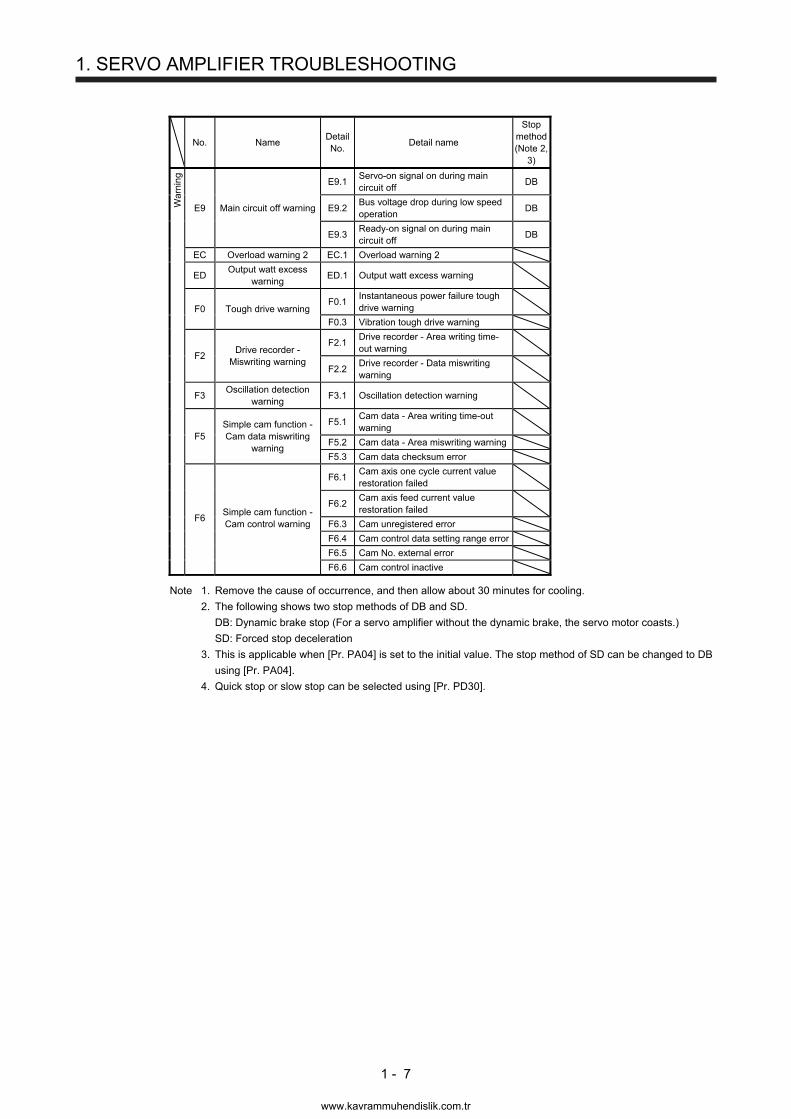
1.3 Warning list
No. Name Detail No.
Detail name
Stop method(Note 2,
3)
W
arni
ng
90.1 Home position return incomplete
90 Home position return incomplete warning
90.2 Home position return abnormal termination
90.5 Z-phase unpassed
91
Servo amplifier overheat warning
(Note 1) 91.1
Main circuit device overheat warning
92
Battery cable disconnection warning
92.1 Encoder battery cable disconnection warning
92.3 Battery degradation
96 Home position setting
warning
96.1 In-position warning at home positioning
96.2 Command input warning at home positioning
96.3 Servo off warning at home positioning
97 Program operation
disabled/next station position warning
97.1 Program operation disabled warning
98 Software limit warning
98.1 Forward rotation-side software stroke limit reached
98.2 Reverse rotation-side software stroke limit reached
99 Stroke limit warning
99.1 Forward rotation stroke end off (Note 4)
99.2 Reverse rotation stroke end off (Note 4)
9B Error excessive
warning
9B.1 Excess droop pulse 1 warning
9B.3 Excess droop pulse 2 warning
9B.4 Error excessive warning during 0 torque limit
9F Battery warning 9F.1 Low battery
E0
Excessive regeneration warning
E0.1 Excessive regeneration warning
E1 Overload warning 1
E1.1 Thermal overload warning 1 during operation
E1.2 Thermal overload warning 2 during operation
E1.3 Thermal overload warning 3 during operation
E1.4 Thermal overload warning 4 during operation
E1.5 Thermal overload warning 1 during a stop
E1.6 Thermal overload warning 2 during a stop
E1.7 Thermal overload warning 3 during a stop
E1.8 Thermal overload warning 4 during a stop
E3 Absolute position counter warning
E3.2 Absolute position counter warning
E3.5 Encoder absolute positioning counter warning
E4 Parameter warning E4.1 Parameter setting range error warning
E6 Servo forced stop
warning E6.1 Forced stop warning SD
E7 Controller forced stop
warning E7.1 Controller forced stop warning SD
E8 Cooling fan speed reduction warning
E8.1 Decreased cooling fan speed warning
www.kavrammuhendislik.com.tr
1. SERVO AMPLIFIER TROUBLESHOOTING
1 - 7
No. Name Detail No.
Detail name
Stop method(Note 2,
3)
War
ning
E9 Main circuit off warning
E9.1 Servo-on signal on during main circuit off
DB
E9.2 Bus voltage drop during low speed operation
DB
E9.3 Ready-on signal on during main circuit off
DB
EC Overload warning 2 EC.1 Overload warning 2
ED Output watt excess
warning ED.1 Output watt excess warning
F0 Tough drive warning F0.1
Instantaneous power failure tough drive warning
F0.3 Vibration tough drive warning
F2 Drive recorder -
Miswriting warning
F2.1 Drive recorder - Area writing time-out warning
F2.2 Drive recorder - Data miswriting warning
F3 Oscillation detection
warning F3.1 Oscillation detection warning
F5 Simple cam function - Cam data miswriting
warning
F5.1 Cam data - Area writing time-out warning
F5.2 Cam data - Area miswriting warning
F5.3 Cam data checksum error
F6.1 Cam axis one cycle current value restoration failed
F6 Simple cam function - Cam control warning
F6.2 Cam axis feed current value restoration failed
F6.3 Cam unregistered error
F6.4 Cam control data setting range error
F6.5 Cam No. external error
F6.6 Cam control inactive
Note 1. Remove the cause of occurrence, and then allow about 30 minutes for cooling.
2. The following shows two stop methods of DB and SD.
DB: Dynamic brake stop (For a servo amplifier without the dynamic brake, the servo motor coasts.)
SD: Forced stop deceleration
3. This is applicable when [Pr. PA04] is set to the initial value. The stop method of SD can be changed to DB
using [Pr. PA04].
4. Quick stop or slow stop can be selected using [Pr. PD30].
www.kavrammuhendislik.com.tr
1. SERVO AMPLIFIER TROUBLESHOOTING
1 - 8
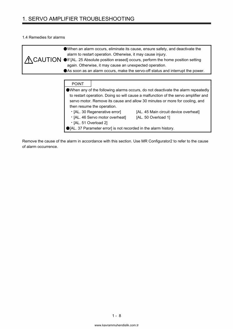
1.4 Remedies for alarms
CAUTION
When an alarm occurs, eliminate its cause, ensure safety, and deactivate the alarm to restart operation. Otherwise, it may cause injury.
If [AL. 25 Absolute position erased] occurs, perform the home position setting again. Otherwise, it may cause an unexpected operation.
As soon as an alarm occurs, make the servo-off status and interrupt the power.
POINT
When any of the following alarms occurs, do not deactivate the alarm repeatedly to restart operation. Doing so will cause a malfunction of the servo amplifier and servo motor. Remove its cause and allow 30 minutes or more for cooling, and then resume the operation.
[AL. 30 Regenerative error] [AL. 45 Main circuit device overheat]
[AL. 46 Servo motor overheat] [AL. 50 Overload 1]
[AL. 51 Overload 2]
[AL. 37 Parameter error] is not recorded in the alarm history.
Remove the cause of the alarm in accordance with this section. Use MR Configurator2 to refer to the cause of alarm occurrence.
www.kavrammuhendislik.com.tr
1. SERVO AMPLIFIER TROUBLESHOOTING
1 - 9
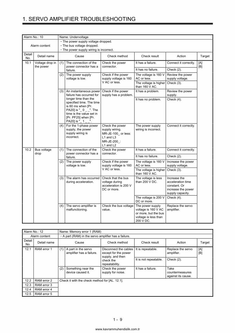
Alarm No.: 10 Name: Undervoltage
Alarm content The power supply voltage dropped. The bus voltage dropped. The power supply wiring is incorrect.
Detail No.
Detail name Cause Check method Check result Action Target
10.1 Voltage drop in the power
(1) The connection of the power connector has a failure.
Check the power connector.
It has a failure. Connect it correctly. [A] [B]
It has no failure. Check (2).
(2) The power supply voltage is low.
Check if the power supply voltage is 160 V AC or less.
The voltage is 160 V AC or less.
Review the power supply voltage.
The voltage is higher than 160 V AC.
Check (3).
(3) An instantaneous power failure has occurred for longer time than the specified time. The time is 60 ms when [Pr. PA20] is "_ 0 _ _". The time is the value set in [Pr. PF25] when [Pr. PA20] is "_ 1 _ _".
Check if the power supply has a problem.
It has a problem. Review the power supply.
It has no problem. Check (4).
(4) For the 1-phase power supply, the power supply wiring is incorrect.
Check the power supply wiring. MR-JE-100_ or less:L1 and L3 MR-JE-200_: L1 and L2
The power supply wiring is incorrect.
Connect it correctly.
10.2 Bus voltage drop
(1) The connection of the power connector has a failure.
Check the power connector.
It has a failure. Connect it correctly.
It has no failure. Check (2).
(2) The power supply voltage is low.
Check if the power supply voltage is 160 V AC or less.
The voltage is 160 V AC or less.
Increase the power supply voltage.
The voltage is higher than 160 V AC.
Check (3).
(3) The alarm has occurred during acceleration.
Check that the bus voltage during acceleration is 200 V DC or more.
The voltage is less than 200 V DC.
Increase the acceleration time constant. Or increase the power supply capacity.
The voltage is 200 V DC or more.
Check (4).
(4) The servo amplifier is malfunctioning.
Check the bus voltage value.
The power supply voltage is 160 V AC or more, but the bus voltage is less than 200 V DC.
Replace the servo amplifier.
Alarm No.: 12 Name: Memory error 1 (RAM)
Alarm content A part (RAM) in the servo amplifier has a failure.
Detail No.
Detail name Cause Check method Check result Action Target
12.1 RAM error 1 (1) A part in the servo amplifier has a failure.
Disconnect the cables except for the power supply, and then check the repeatability.
It is repeatable. Replace the servo amplifier.
[A] [B]
It is not repeatable. Check (2).
(2) Something near the device caused it.
Check the power supply for noise.
It has a failure. Take countermeasures against its cause.
12.2 RAM error 2 Check it with the check method for [AL. 12.1].
12.3 RAM error 3
12.4 RAM error 4
12.5 RAM error 5
www.kavrammuhendislik.com.tr
1. SERVO AMPLIFIER TROUBLESHOOTING
1 - 10
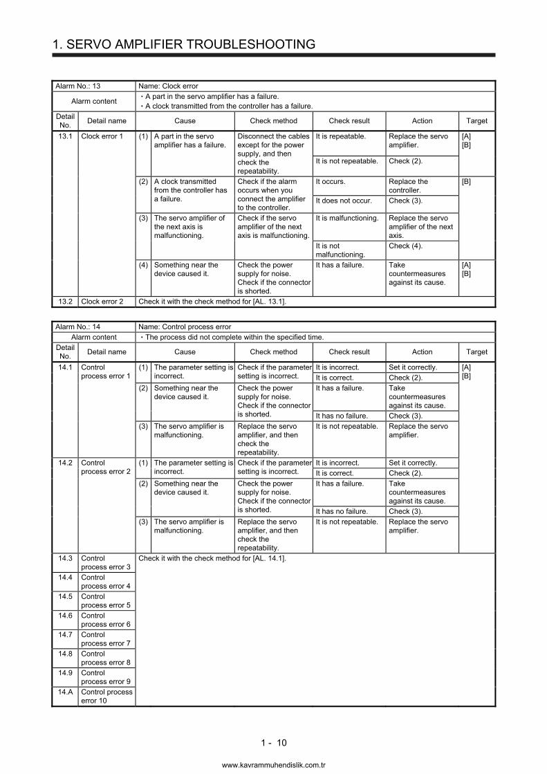
Alarm No.: 13 Name: Clock error
Alarm content A part in the servo amplifier has a failure. A clock transmitted from the controller has a failure.
Detail No.
Detail name Cause Check method Check result Action Target
13.1 Clock error 1 (1) A part in the servo amplifier has a failure.
Disconnect the cables except for the power supply, and then check the repeatability.
It is repeatable. Replace the servo amplifier.
[A] [B]
It is not repeatable. Check (2).
(2) A clock transmitted from the controller has a failure.
Check if the alarm occurs when you connect the amplifier to the controller.
It occurs. Replace the controller.
[B]
It does not occur. Check (3).
(3) The servo amplifier of the next axis is malfunctioning.
Check if the servo amplifier of the next axis is malfunctioning.
It is malfunctioning. Replace the servo amplifier of the next axis.
It is not malfunctioning.
Check (4).
(4) Something near the device caused it.
Check the power supply for noise. Check if the connector is shorted.
It has a failure. Take countermeasures against its cause.
[A] [B]
13.2 Clock error 2 Check it with the check method for [AL. 13.1].
Alarm No.: 14 Name: Control process error
Alarm content The process did not complete within the specified time.
Detail No.
Detail name Cause Check method Check result Action Target
14.1 Control process error 1
(1) The parameter setting is incorrect.
Check if the parameter setting is incorrect.
It is incorrect. Set it correctly. [A] [B] It is correct. Check (2).
(2) Something near the device caused it.
Check the power supply for noise. Check if the connector is shorted.
It has a failure. Take countermeasures against its cause.
It has no failure. Check (3).
(3) The servo amplifier is malfunctioning.
Replace the servo amplifier, and then check the repeatability.
It is not repeatable. Replace the servo amplifier.
14.2 Control process error 2
(1) The parameter setting is incorrect.
Check if the parameter setting is incorrect.
It is incorrect. Set it correctly.
It is correct. Check (2).
(2) Something near the device caused it.
Check the power supply for noise. Check if the connector is shorted.
It has a failure. Take countermeasures against its cause.
It has no failure. Check (3).
(3) The servo amplifier is malfunctioning.
Replace the servo amplifier, and then check the repeatability.
It is not repeatable. Replace the servo amplifier.
14.3 Control process error 3
Check it with the check method for [AL. 14.1].
14.4 Control process error 4
14.5 Control process error 5
14.6 Control process error 6
14.7 Control process error 7
14.8 Control process error 8
14.9 Control process error 9
14.A Control process error 10
www.kavrammuhendislik.com.tr
1. SERVO AMPLIFIER TROUBLESHOOTING
1 - 11
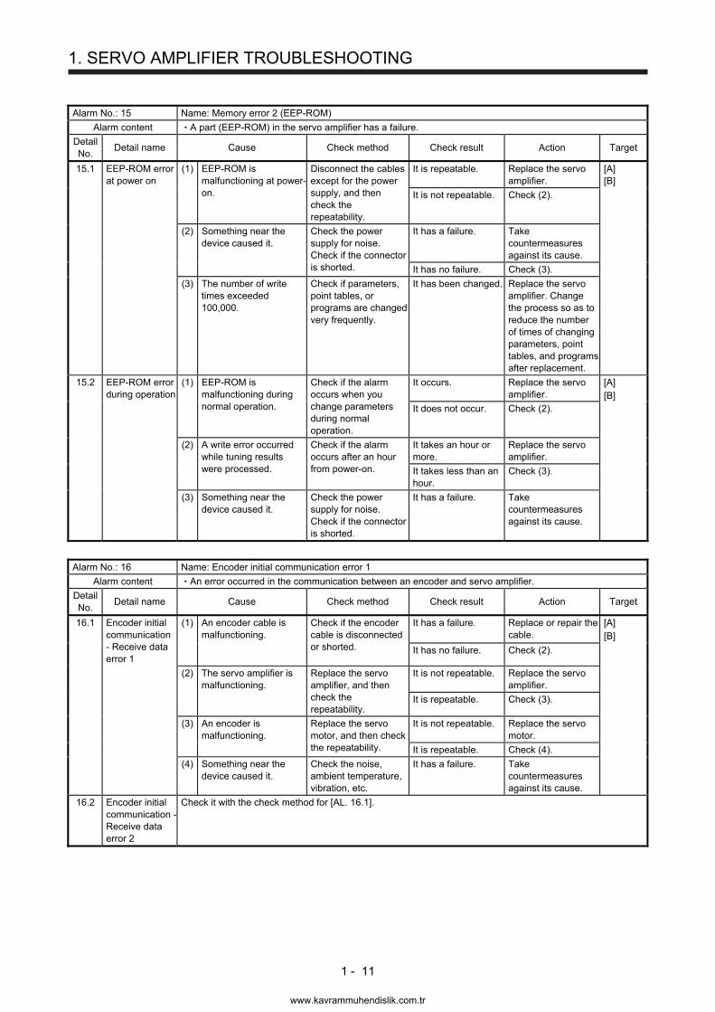
Alarm No.: 15 Name: Memory error 2 (EEP-ROM)
Alarm content A part (EEP-ROM) in the servo amplifier has a failure.
Detail No.
Detail name Cause Check method Check result Action Target
15.1 EEP-ROM error at power on
(1) EEP-ROM is malfunctioning at power-on.
Disconnect the cables except for the power supply, and then check the repeatability.
It is repeatable. Replace the servo amplifier.
[A] [B]
It is not repeatable. Check (2).
(2) Something near the device caused it.
Check the power supply for noise. Check if the connector is shorted.
It has a failure. Take countermeasures against its cause.
It has no failure. Check (3).
(3) The number of write times exceeded 100,000.
Check if parameters, point tables, or programs are changed very frequently.
It has been changed. Replace the servo amplifier. Change the process so as to reduce the number of times of changing parameters, point tables, and programs after replacement.
15.2 EEP-ROM error during operation
(1) EEP-ROM is malfunctioning during normal operation.
Check if the alarm occurs when you change parameters during normal operation.
It occurs. Replace the servo amplifier.
[A] [B] It does not occur. Check (2).
(2) A write error occurred while tuning results were processed.
Check if the alarm occurs after an hour from power-on.
It takes an hour or more.
Replace the servo amplifier.
It takes less than an hour.
Check (3).
(3) Something near the device caused it.
Check the power supply for noise. Check if the connector is shorted.
It has a failure. Take countermeasures against its cause.
Alarm No.: 16 Name: Encoder initial communication error 1
Alarm content An error occurred in the communication between an encoder and servo amplifier.
Detail No.
Detail name Cause Check method Check result Action Target
16.1 Encoder initial communication - Receive data error 1
(1) An encoder cable is malfunctioning.
Check if the encoder cable is disconnected or shorted.
It has a failure. Replace or repair the cable.
[A] [B]
It has no failure. Check (2).
(2) The servo amplifier is malfunctioning.
Replace the servo amplifier, and then check the repeatability.
It is not repeatable. Replace the servo amplifier.
It is repeatable. Check (3).
(3) An encoder is malfunctioning.
Replace the servo motor, and then check the repeatability.
It is not repeatable. Replace the servo motor.
It is repeatable. Check (4).
(4) Something near the device caused it.
Check the noise, ambient temperature, vibration, etc.
It has a failure. Take countermeasures against its cause.
16.2 Encoder initial communication - Receive data error 2
Check it with the check method for [AL. 16.1].
www.kavrammuhendislik.com.tr
1. SERVO AMPLIFIER TROUBLESHOOTING
1 - 12
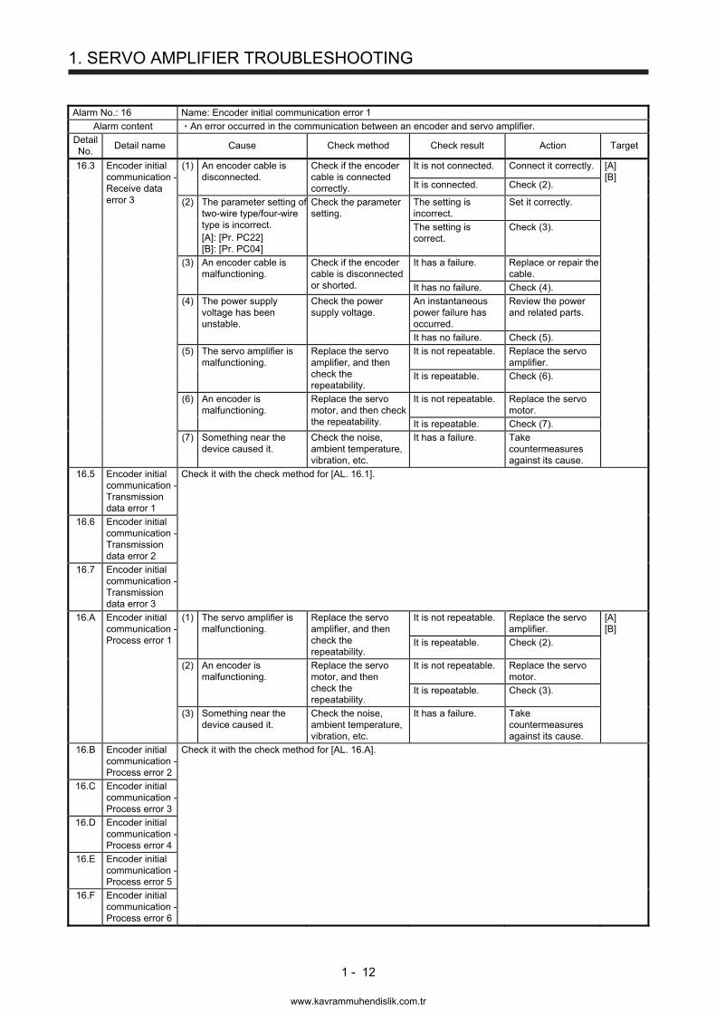
Alarm No.: 16 Name: Encoder initial communication error 1
Alarm content An error occurred in the communication between an encoder and servo amplifier.
Detail No.
Detail name Cause Check method Check result Action Target
16.3 Encoder initial communication - Receive data error 3
(1) An encoder cable is disconnected.
Check if the encoder cable is connected correctly.
It is not connected. Connect it correctly. [A] [B]
It is connected. Check (2).
(2) The parameter setting of two-wire type/four-wire type is incorrect. [A]: [Pr. PC22] [B]: [Pr. PC04]
Check the parameter setting.
The setting is incorrect.
Set it correctly.
The setting is correct.
Check (3).
(3) An encoder cable is malfunctioning.
Check if the encoder cable is disconnected or shorted.
It has a failure. Replace or repair the cable.
It has no failure. Check (4).
(4) The power supply voltage has been unstable.
Check the power supply voltage.
An instantaneous power failure has occurred.
Review the power and related parts.
It has no failure. Check (5).
(5) The servo amplifier is malfunctioning.
Replace the servo amplifier, and then check the repeatability.
It is not repeatable. Replace the servo amplifier.
It is repeatable. Check (6).
(6) An encoder is malfunctioning.
Replace the servo motor, and then check the repeatability.
It is not repeatable. Replace the servo motor.
It is repeatable. Check (7).
(7) Something near the device caused it.
Check the noise, ambient temperature, vibration, etc.
It has a failure. Take countermeasures against its cause.
16.5 Encoder initial communication - Transmission data error 1
Check it with the check method for [AL. 16.1].
16.6 Encoder initial communication - Transmission data error 2
16.7 Encoder initial communication - Transmission data error 3
16.A Encoder initial communication - Process error 1
(1) The servo amplifier is malfunctioning.
Replace the servo amplifier, and then check the repeatability.
It is not repeatable. Replace the servo amplifier.
[A] [B]
It is repeatable. Check (2).
(2) An encoder is malfunctioning.
Replace the servo motor, and then check the repeatability.
It is not repeatable. Replace the servo motor.
It is repeatable. Check (3).
(3) Something near the device caused it.
Check the noise, ambient temperature, vibration, etc.
It has a failure. Take countermeasures against its cause.
16.B Encoder initial communication - Process error 2
Check it with the check method for [AL. 16.A].
16.C Encoder initial communication - Process error 3
16.D Encoder initial communication - Process error 4
16.E Encoder initial communication - Process error 5
16.F Encoder initial communication - Process error 6
www.kavrammuhendislik.com.tr
1. SERVO AMPLIFIER TROUBLESHOOTING
1 - 13
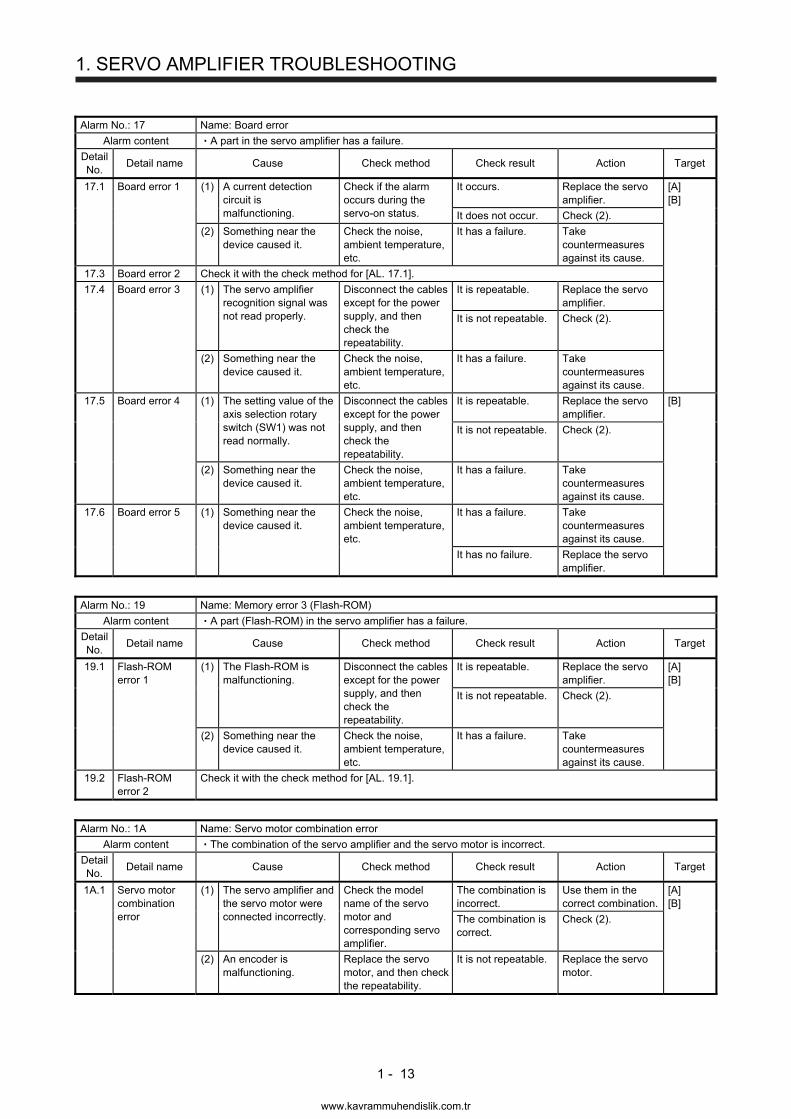
Alarm No.: 17 Name: Board error
Alarm content A part in the servo amplifier has a failure.
Detail No.
Detail name Cause Check method Check result Action Target
17.1 Board error 1 (1) A current detection circuit is malfunctioning.
Check if the alarm occurs during the servo-on status.
It occurs. Replace the servo amplifier.
[A] [B]
It does not occur. Check (2).
(2) Something near the device caused it.
Check the noise, ambient temperature, etc.
It has a failure. Take countermeasures against its cause.
17.3 Board error 2 Check it with the check method for [AL. 17.1].
17.4 Board error 3 (1) The servo amplifier recognition signal was not read properly.
Disconnect the cables except for the power supply, and then check the repeatability.
It is repeatable. Replace the servo amplifier.
It is not repeatable. Check (2).
(2) Something near the device caused it.
Check the noise, ambient temperature, etc.
It has a failure. Take countermeasures against its cause.
17.5 Board error 4 (1) The setting value of the axis selection rotary switch (SW1) was not read normally.
Disconnect the cables except for the power supply, and then check the repeatability.
It is repeatable. Replace the servo amplifier.
[B]
It is not repeatable. Check (2).
(2) Something near the device caused it.
Check the noise, ambient temperature, etc.
It has a failure. Take countermeasures against its cause.
17.6 Board error 5 (1) Something near the device caused it.
Check the noise, ambient temperature, etc.
It has a failure. Take countermeasures against its cause.
It has no failure. Replace the servo amplifier.
Alarm No.: 19 Name: Memory error 3 (Flash-ROM)
Alarm content A part (Flash-ROM) in the servo amplifier has a failure.
Detail No.
Detail name Cause Check method Check result Action Target
19.1 Flash-ROM error 1
(1) The Flash-ROM is malfunctioning.
Disconnect the cables except for the power supply, and then check the repeatability.
It is repeatable. Replace the servo amplifier.
[A] [B]
It is not repeatable. Check (2).
(2) Something near the device caused it.
Check the noise, ambient temperature, etc.
It has a failure. Take countermeasures against its cause.
19.2 Flash-ROM error 2
Check it with the check method for [AL. 19.1].
Alarm No.: 1A Name: Servo motor combination error
Alarm content The combination of the servo amplifier and the servo motor is incorrect.
Detail No.
Detail name Cause Check method Check result Action Target
1A.1 Servo motor combination error
(1) The servo amplifier and the servo motor were connected incorrectly.
Check the model name of the servo motor and corresponding servo amplifier.
The combination is incorrect.
Use them in the correct combination.
[A] [B]
The combination is correct.
Check (2).
(2) An encoder is malfunctioning.
Replace the servo motor, and then check the repeatability.
It is not repeatable. Replace the servo motor.
www.kavrammuhendislik.com.tr
1. SERVO AMPLIFIER TROUBLESHOOTING
1 - 14
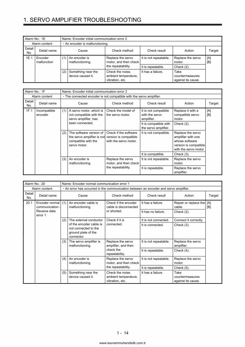
Alarm No.: 1E Name: Encoder initial communication error 2
Alarm content An encoder is malfunctioning.
Detail No.
Detail name Cause Check method Check result Action Target
1E.1 Encoder malfunction
(1) An encoder is malfunctioning.
Replace the servo motor, and then check the repeatability.
It is not repeatable. Replace the servo motor.
[A] [B]
It is repeatable. Check (2).
(2) Something near the device caused it.
Check the noise, ambient temperature, vibration, etc.
It has a failure. Take countermeasures against its cause.
Alarm No.: 1F Name: Encoder initial communication error 3
Alarm content The connected encoder is not compatible with the servo amplifier.
Detail No.
Detail name Cause Check method Check result Action Target
1F.1 Incompatible encoder
(1) A servo motor, which is not compatible with the servo amplifier, has been connected.
Check the model of the servo motor.
It is not compatible with the servo amplifier.
Replace it with a compatible servo motor.
[A] [B]
It is compatible with the servo amplifier.
Check (2).
(2) The software version of the servo amplifier is not compatible with the servo motor.
Check if the software version is compatible with the servo motor.
It is not compatible. Replace the servo amplifier with one whose software version is compatible with the servo motor.
It is compatible. Check (3).
(3) An encoder is malfunctioning.
Replace the servo motor, and then check the repeatability.
It is not repeatable. Replace the servo motor.
It is repeatable. Replace the servo amplifier.
Alarm No.: 20 Name: Encoder normal communication error 1
Alarm content An error has occurred in the communication between an encoder and servo amplifier.
Detail No.
Detail name Cause Check method Check result Action Target
20.1 Encoder normal communication - Receive data error 1
(1) An encoder cable is malfunctioning.
Check if the encoder cable is disconnected or shorted.
It has a failure. Repair or replace the cable.
[A] [B]
It has no failure. Check (2).
(2) The external conductor of the encoder cable is not connected to the ground plate of the connector.
Check if it is connected.
It is not connected. Connect it correctly.
It is connected. Check (3).
(3) The servo amplifier is malfunctioning.
Replace the servo amplifier, and then check the repeatability.
It is not repeatable. Replace the servo amplifier.
It is repeatable. Check (4).
(4) An encoder is malfunctioning.
Replace the servo motor, and then check the repeatability.
It is not repeatable. Replace the servo motor.
It is repeatable. Check (5).
(5) Something near the device caused it.
Check the noise, ambient temperature, vibration, etc.
It has a failure. Take countermeasures against its cause.
www.kavrammuhendislik.com.tr
1. SERVO AMPLIFIER TROUBLESHOOTING
1 - 15
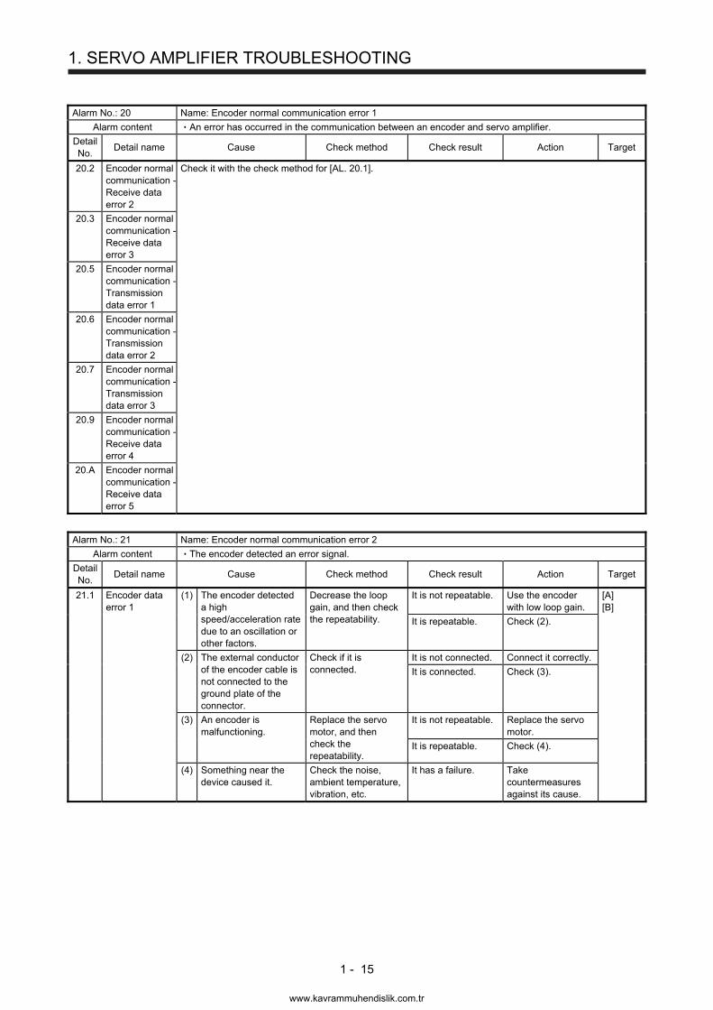
Alarm No.: 20 Name: Encoder normal communication error 1
Alarm content An error has occurred in the communication between an encoder and servo amplifier.
Detail No.
Detail name Cause Check method Check result Action Target
20.2 Encoder normal communication - Receive data error 2
Check it with the check method for [AL. 20.1].
20.3 Encoder normal communication - Receive data error 3
20.5 Encoder normal communication - Transmission data error 1
20.6 Encoder normal communication - Transmission data error 2
20.7 Encoder normal communication - Transmission data error 3
20.9 Encoder normal communication - Receive data error 4
20.A Encoder normal communication - Receive data error 5
Alarm No.: 21 Name: Encoder normal communication error 2
Alarm content The encoder detected an error signal.
Detail No.
Detail name Cause Check method Check result Action Target
21.1 Encoder data error 1
(1) The encoder detected a high speed/acceleration rate due to an oscillation or other factors.
Decrease the loop gain, and then check the repeatability.
It is not repeatable. Use the encoder with low loop gain.
[A] [B]
It is repeatable. Check (2).
(2) The external conductor of the encoder cable is not connected to the ground plate of the connector.
Check if it is connected.
It is not connected. Connect it correctly.
It is connected. Check (3).
(3) An encoder is malfunctioning.
Replace the servo motor, and then check the repeatability.
It is not repeatable. Replace the servo motor.
It is repeatable. Check (4).
(4) Something near the device caused it.
Check the noise, ambient temperature, vibration, etc.
It has a failure. Take countermeasures against its cause.
www.kavrammuhendislik.com.tr
1. SERVO AMPLIFIER TROUBLESHOOTING
1 - 16
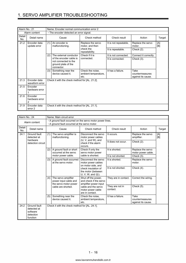
Alarm No.: 21 Name: Encoder normal communication error 2
Alarm content The encoder detected an error signal.
Detail No.
Detail name Cause Check method Check result Action Target
21.2 Encoder data update error
(1) An encoder is malfunctioning.
Replace the servo motor, and then check the repeatability.
It is not repeatable. Replace the servo motor.
[A] [B]
It is repeatable. Check (2).
(2) The external conductor of the encoder cable is not connected to the ground plate of the connector.
Check if it is connected.
It is not connected. Connect it correctly.
It is connected. Check (3).
(3) Something near the device caused it.
Check the noise, ambient temperature, etc.
It has a failure. Take countermeasures against its cause.
21.3 Encoder data waveform error
Check it with the check method for [AL. 21.2].
21.5 Encoder hardware error 1
21.6 Encoder hardware error 2
21.9 Encoder data error 2
Check it with the check method for [AL. 21.1].
Alarm No.: 24 Name: Main circuit error
Alarm content A ground fault occurred on the servo motor power lines. A ground fault occurred at the servo motor.
Detail No.
Detail name Cause Check method Check result Action Target
24.1 Ground fault detected at hardware detection circuit
(1) The servo amplifier is malfunctioning.
Disconnect the servo motor power cables (U, V, and W), and check if the alarm occurs.
It occurs. Replace the servo amplifier.
[A] [B]
It does not occur. Check (2).
(2) A ground fault or short occurred at the servo motor power cable.
Check if only the servo motor power cable is shorted.
It is shorted. Replace the servo motor power cable.
It is not shorted. Check (3).
(3) A ground fault occurred at the servo motor.
Disconnect the servo motor power cables on motor side, and check insulation of the motor (between U, V, W, and ).
It is shorted. Replace the servo motor.
It is not shorted. Check (4).
(4) The servo amplifier power input cable and the servo motor power cable are shorted.
Shut off the power, and check if the servo amplifier power input cable and the servo motor power cable are in contact.
They are in contact. Correct the wiring.
They are not in contact.
Check (5).
(5) Something near the device caused it.
Check the noise, ambient temperature, etc.
It has a failure. Take countermeasures against its cause.
24.2 Ground fault detected at software detection function
Check it with the check method for [AL. 24.1].
www.kavrammuhendislik.com.tr
1. SERVO AMPLIFIER TROUBLESHOOTING
1 - 17
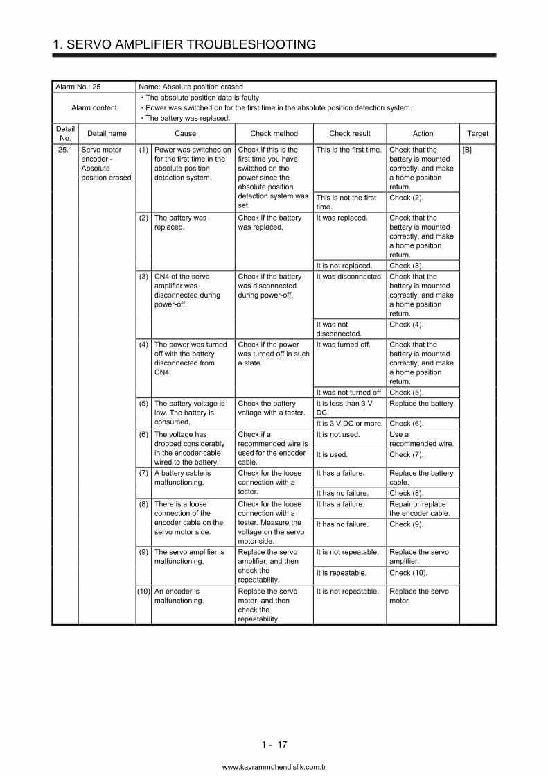
Alarm No.: 25 Name: Absolute position erased
Alarm content The absolute position data is faulty. Power was switched on for the first time in the absolute position detection system. The battery was replaced.
Detail No.
Detail name Cause Check method Check result Action Target
25.1 Servo motor encoder - Absolute position erased
(1) Power was switched on for the first time in the absolute position detection system.
Check if this is the first time you have switched on the power since the absolute position detection system was set.
This is the first time. Check that the battery is mounted correctly, and make a home position return.
[B]
This is not the first time.
Check (2).
(2) The battery was replaced.
Check if the battery was replaced.
It was replaced. Check that the battery is mounted correctly, and make a home position return.
It is not replaced. Check (3).
(3) CN4 of the servo amplifier was disconnected during power-off.
Check if the battery was disconnected during power-off.
It was disconnected. Check that the battery is mounted correctly, and make a home position return.
It was not disconnected.
Check (4).
(4) The power was turned off with the battery disconnected from CN4.
Check if the power was turned off in such a state.
It was turned off. Check that the battery is mounted correctly, and make a home position return.
It was not turned off. Check (5).
(5) The battery voltage is low. The battery is consumed.
Check the battery voltage with a tester.
It is less than 3 V DC.
Replace the battery.
It is 3 V DC or more. Check (6).
(6) The voltage has dropped considerably in the encoder cable wired to the battery.
Check if a recommended wire is used for the encoder cable.
It is not used. Use a recommended wire.
It is used. Check (7).
(7) A battery cable is malfunctioning.
Check for the loose connection with a tester.
It has a failure. Replace the battery cable.
It has no failure. Check (8).
(8) There is a loose connection of the encoder cable on the servo motor side.
Check for the loose connection with a tester. Measure the voltage on the servo motor side.
It has a failure. Repair or replace the encoder cable.
It has no failure. Check (9).
(9) The servo amplifier is malfunctioning.
Replace the servo amplifier, and then check the repeatability.
It is not repeatable. Replace the servo amplifier.
It is repeatable. Check (10).
(10) An encoder is malfunctioning.
Replace the servo motor, and then check the repeatability.
It is not repeatable. Replace the servo motor.
www.kavrammuhendislik.com.tr
1. SERVO AMPLIFIER TROUBLESHOOTING
1 - 18
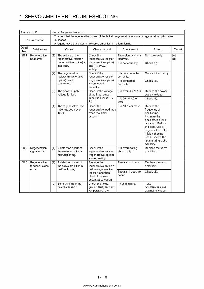
Alarm No.: 30 Name: Regenerative error
Alarm content The permissible regenerative power of the built-in regenerative resistor or regenerative option was exceeded. A regenerative transistor in the servo amplifier is malfunctioning.
Detail No.
Detail name Cause Check method Check result Action Target
30.1 Regeneration heat error
(1) The setting of the regenerative resistor (regenerative option) is incorrect.
Check the regenerative resistor (regenerative option) and [Pr. PA02] setting.
The setting value is incorrect.
Set it correctly. [A] [B]
It is set correctly. Check (2).
(2) The regenerative resistor (regenerative option) is not connected.
Check if the regenerative resistor (regenerative option) is connected correctly.
It is not connected correctly.
Connect it correctly.
It is connected correctly.
Check (3).
(3) The power supply voltage is high.
Check if the voltage of the input power supply is over 264 V AC.
It is over 264 V AC. Reduce the power supply voltage.
It is 264 V AC or less.
Check (4).
(4) The regenerative load ratio has been over 100%.
Check the regenerative load ratio when the alarm occurs.
It is 100% or more. Reduce the frequency of positioning. Increase the deceleration time constant. Reduce the load. Use a regenerative option if it is not being used. Review the regenerative option capacity.
30.2 Regeneration signal error
(1) A detection circuit of the servo amplifier is malfunctioning.
Check if the regenerative resistor (regenerative option) is overheating.
It is overheating abnormally.
Replace the servo amplifier.
30.3 Regeneration feedback signal error
(1) A detection circuit of the servo amplifier is malfunctioning.
Remove the regenerative option or built-in regenerative resistor, and then check if the alarm occurs at power-on.
The alarm occurs. Replace the servo amplifier.
The alarm does not occur.
Check (2).
(2) Something near the device caused it.
Check the noise, ground fault, ambient temperature, etc.
It has a failure. Take countermeasures against its cause.
www.kavrammuhendislik.com.tr
1. SERVO AMPLIFIER TROUBLESHOOTING
1 - 19
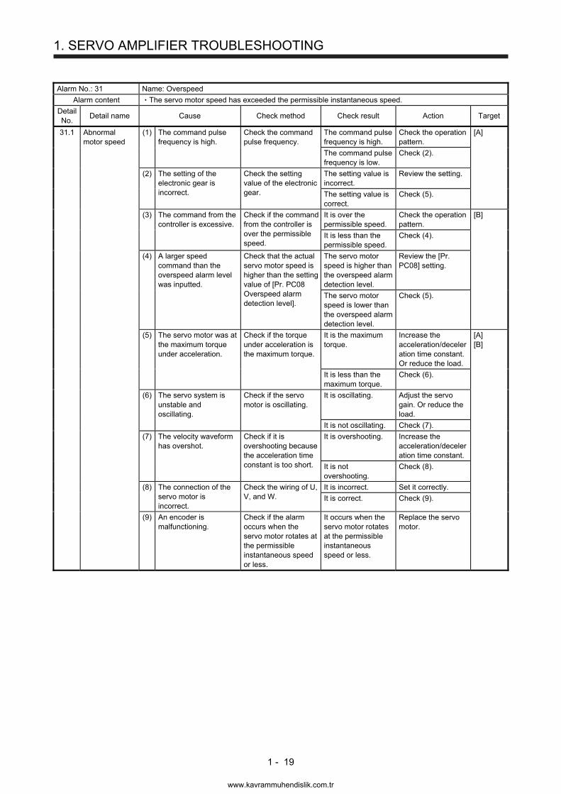
Alarm No.: 31 Name: Overspeed
Alarm content The servo motor speed has exceeded the permissible instantaneous speed.
Detail No.
Detail name Cause Check method Check result Action Target
31.1 Abnormal motor speed
(1) The command pulse frequency is high.
Check the command pulse frequency.
The command pulse frequency is high.
Check the operation pattern.
[A]
The command pulse frequency is low.
Check (2).
(2) The setting of the electronic gear is incorrect.
Check the setting value of the electronic gear.
The setting value is incorrect.
Review the setting.
The setting value is correct.
Check (5).
(3) The command from the controller is excessive.
Check if the command from the controller is over the permissible speed.
It is over the permissible speed.
Check the operation pattern.
[B]
It is less than the permissible speed.
Check (4).
(4) A larger speed command than the overspeed alarm level was inputted.
Check that the actual servo motor speed is higher than the setting value of [Pr. PC08 Overspeed alarm detection level].
The servo motor speed is higher than the overspeed alarm detection level.
Review the [Pr. PC08] setting.
The servo motor speed is lower than the overspeed alarm detection level.
Check (5).
(5) The servo motor was at the maximum torque under acceleration.
Check if the torque under acceleration is the maximum torque.
It is the maximum torque.
Increase the acceleration/deceleration time constant. Or reduce the load.
[A] [B]
It is less than the maximum torque.
Check (6).
(6) The servo system is unstable and oscillating.
Check if the servo motor is oscillating.
It is oscillating. Adjust the servo gain. Or reduce the load.
It is not oscillating. Check (7).
(7) The velocity waveform has overshot.
Check if it is overshooting because the acceleration time constant is too short.
It is overshooting. Increase the acceleration/deceleration time constant.
It is not overshooting.
Check (8).
(8) The connection of the servo motor is incorrect.
Check the wiring of U, V, and W.
It is incorrect. Set it correctly.
It is correct. Check (9).
(9) An encoder is malfunctioning.
Check if the alarm occurs when the servo motor rotates at the permissible instantaneous speed or less.
It occurs when the servo motor rotates at the permissible instantaneous speed or less.
Replace the servo motor.
www.kavrammuhendislik.com.tr
1. SERVO AMPLIFIER TROUBLESHOOTING
1 - 20
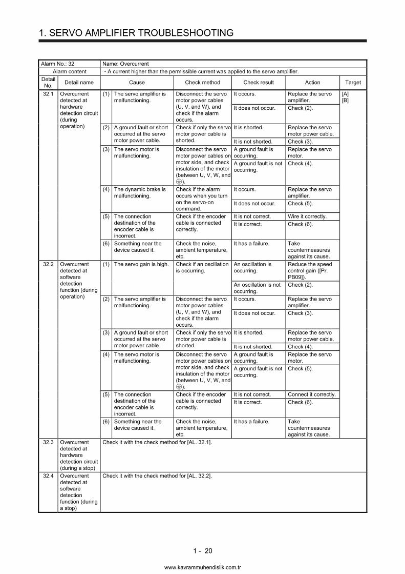
Alarm No.: 32 Name: Overcurrent
Alarm content A current higher than the permissible current was applied to the servo amplifier.
Detail No.
Detail name Cause Check method Check result Action Target
32.1 Overcurrent detected at hardware detection circuit (during operation)
(1) The servo amplifier is malfunctioning.
Disconnect the servo motor power cables (U, V, and W), and check if the alarm occurs.
It occurs. Replace the servo amplifier.
[A] [B]
It does not occur. Check (2).
(2) A ground fault or short occurred at the servo motor power cable.
Check if only the servo motor power cable is shorted.
It is shorted. Replace the servo motor power cable.
It is not shorted. Check (3).
(3) The servo motor is malfunctioning.
Disconnect the servo motor power cables on motor side, and check insulation of the motor (between U, V, W, and
).
A ground fault is occurring.
Replace the servo motor.
A ground fault is not occurring.
Check (4).
(4) The dynamic brake is malfunctioning.
Check if the alarm occurs when you turn on the servo-on command.
It occurs. Replace the servo amplifier.
It does not occur. Check (5).
(5) The connection destination of the encoder cable is incorrect.
Check if the encoder cable is connected correctly.
It is not correct. Wire it correctly.
It is correct. Check (6).
(6) Something near the device caused it.
Check the noise, ambient temperature, etc.
It has a failure. Take countermeasures against its cause.
32.2 Overcurrent detected at software detection function (during operation)
(1) The servo gain is high. Check if an oscillation is occurring.
An oscillation is occurring.
Reduce the speed control gain ([Pr. PB09]).
An oscillation is not occurring.
Check (2).
(2) The servo amplifier is malfunctioning.
Disconnect the servo motor power cables (U, V, and W), and check if the alarm occurs.
It occurs. Replace the servo amplifier.
It does not occur. Check (3).
(3) A ground fault or short occurred at the servo motor power cable.
Check if only the servo motor power cable is shorted.
It is shorted. Replace the servo motor power cable.
It is not shorted. Check (4).
(4) The servo motor is malfunctioning.
Disconnect the servo motor power cables on motor side, and check insulation of the motor (between U, V, W, and
).
A ground fault is occurring.
Replace the servo motor.
A ground fault is not occurring.
Check (5).
(5) The connection destination of the encoder cable is incorrect.
Check if the encoder cable is connected correctly.
It is not correct. Connect it correctly.
It is correct. Check (6).
(6) Something near the device caused it.
Check the noise, ambient temperature, etc.
It has a failure. Take countermeasures against its cause.
32.3 Overcurrent detected at hardware detection circuit (during a stop)
Check it with the check method for [AL. 32.1].
32.4 Overcurrent detected at software detection function (during a stop)
Check it with the check method for [AL. 32.2].
www.kavrammuhendislik.com.tr
1. SERVO AMPLIFIER TROUBLESHOOTING
1 - 21
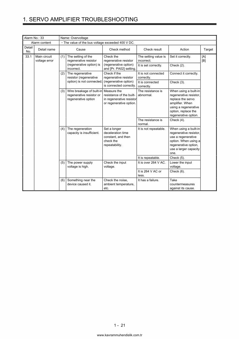
Alarm No.: 33 Name: Overvoltage
Alarm content The value of the bus voltage exceeded 400 V DC.
Detail No.
Detail name Cause Check method Check result Action Target
33.1 Main circuit voltage error
(1) The setting of the regenerative resistor (regenerative option) is incorrect.
Check the regenerative resistor (regenerative option) and [Pr. PA02] setting.
The setting value is incorrect.
Set it correctly. [A] [B]
It is set correctly. Check (2).
(2) The regenerative resistor (regenerative option) is not connected.
Check if the regenerative resistor (regenerative option) is connected correctly.
It is not connected correctly.
Connect it correctly.
It is connected correctly.
Check (3).
(3) Wire breakage of built-in regenerative resistor or regenerative option
Measure the resistance of the built-in regenerative resistor or regenerative option.
The resistance is abnormal.
When using a built-in regenerative resistor, replace the servo amplifier. When using a regenerative option, replace the regenerative option.
The resistance is normal.
Check (4).
(4) The regeneration capacity is insufficient.
Set a longer deceleration time constant, and then check the repeatability.
It is not repeatable. When using a built-in regenerative resistor, use a regenerative option. When using a regenerative option, use a larger capacity one.
It is repeatable. Check (5).
(5) The power supply voltage is high.
Check the input voltage.
It is over 264 V AC. Lower the input voltage.
It is 264 V AC or less.
Check (6).
(6) Something near the device caused it.
Check the noise, ambient temperature, etc.
It has a failure. Take countermeasures against its cause.
www.kavrammuhendislik.com.tr
1. SERVO AMPLIFIER TROUBLESHOOTING
1 - 22
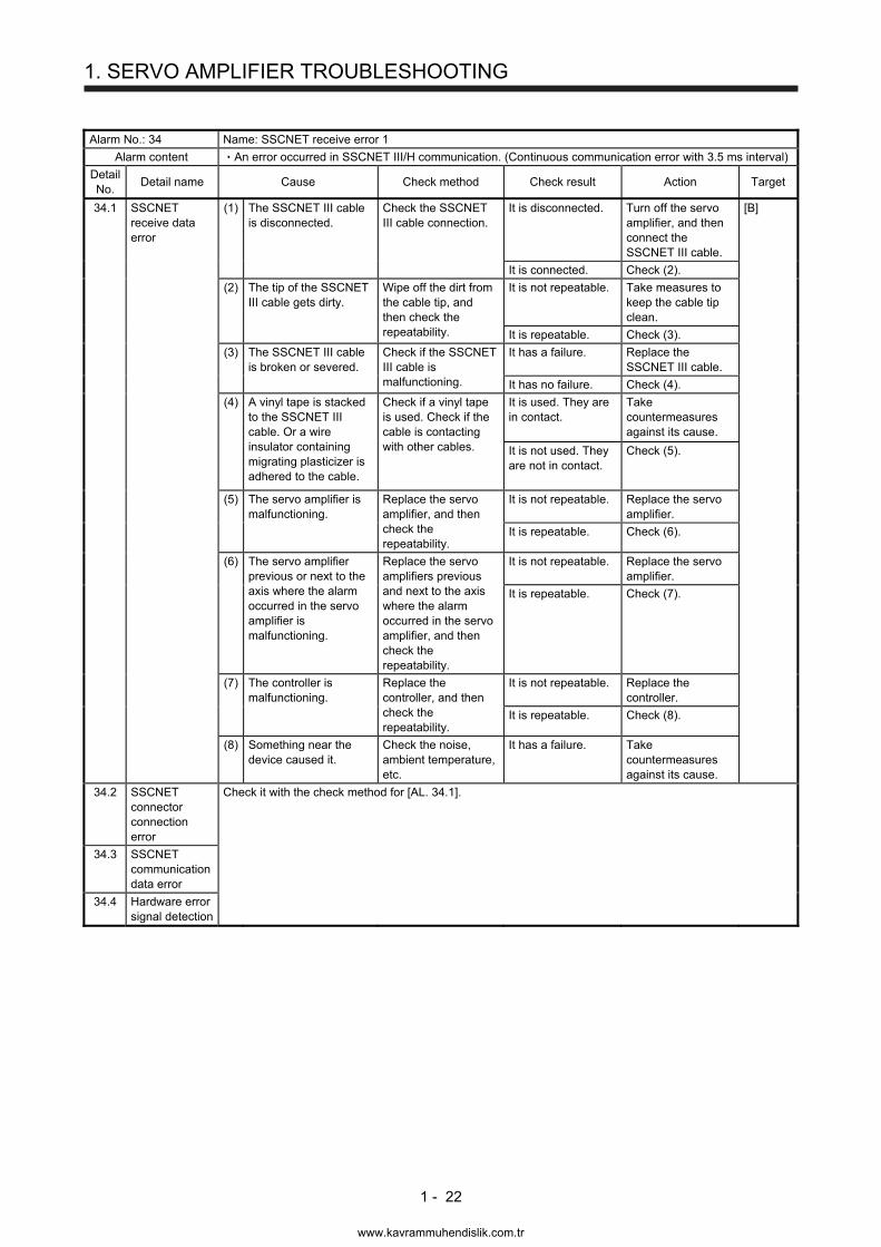
Alarm No.: 34 Name: SSCNET receive error 1
Alarm content An error occurred in SSCNET III/H communication. (Continuous communication error with 3.5 ms interval)
Detail No.
Detail name Cause Check method Check result Action Target
34.1 SSCNET receive data error
(1) The SSCNET III cable is disconnected.
Check the SSCNET III cable connection.
It is disconnected. Turn off the servo amplifier, and then connect the SSCNET III cable.
[B]
It is connected. Check (2).
(2) The tip of the SSCNET III cable gets dirty.
Wipe off the dirt from the cable tip, and then check the repeatability.
It is not repeatable. Take measures to keep the cable tip clean.
It is repeatable. Check (3).
(3) The SSCNET III cable is broken or severed.
Check if the SSCNET III cable is malfunctioning.
It has a failure. Replace the SSCNET III cable.
It has no failure. Check (4).
(4) A vinyl tape is stacked to the SSCNET III cable. Or a wire insulator containing migrating plasticizer is adhered to the cable.
Check if a vinyl tape is used. Check if the cable is contacting with other cables.
It is used. They are in contact.
Take countermeasures against its cause.
It is not used. They are not in contact.
Check (5).
(5) The servo amplifier is malfunctioning.
Replace the servo amplifier, and then check the repeatability.
It is not repeatable. Replace the servo amplifier.
It is repeatable. Check (6).
(6) The servo amplifier previous or next to the axis where the alarm occurred in the servo amplifier is malfunctioning.
Replace the servo amplifiers previous and next to the axis where the alarm occurred in the servo amplifier, and then check the repeatability.
It is not repeatable. Replace the servo amplifier.
It is repeatable. Check (7).
(7) The controller is malfunctioning.
Replace the controller, and then check the repeatability.
It is not repeatable. Replace the controller.
It is repeatable. Check (8).
(8) Something near the device caused it.
Check the noise, ambient temperature, etc.
It has a failure. Take countermeasures against its cause.
34.2 SSCNET connector connection error
Check it with the check method for [AL. 34.1].
34.3 SSCNET communication data error
34.4 Hardware error signal detection
www.kavrammuhendislik.com.tr
1. SERVO AMPLIFIER TROUBLESHOOTING
1 - 23
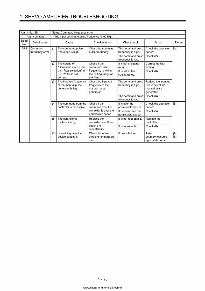
Alarm No.: 35 Name: Command frequency error
Alarm content The input command pulse frequency is too high.
Detail No.
Detail name Cause Check method Check result Action Target
35.1 Command frequency error
(1) The command pulse frequency is high.
Check the command pulse frequency.
The command pulse frequency is high.
Check the operation pattern.
[A]
The command pulse frequency is low.
Check (2).
(2) The setting of "Command input pulse train filter selection" in [Pr. PA13] is not correct.
Check if the command pulse frequency is within the setting range of the filter.
It is out of setting range.
Correct the filter setting.
It is within the setting range.
Check (6).
(3) The inputted frequency of the manual pulse generator is high.
Check the inputted frequency of the manual pulse generator.
The command pulse frequency is high.
Reduce the inputted frequency of the manual pulse generator.
The command pulse frequency is low.
Check (6).
(4) The command from the controller is excessive.
Check if the command from the controller is over the permissible speed.
It is over the permissible speed.
Check the operation pattern.
[B]
It is lower than the permissible speed.
Check (5).
(5) The controller is malfunctioning.
Replace the controller, and then check the repeatability.
It is not repeatable. Replace the controller.
It is repeatable. Check (6).
(6) Something near the device caused it.
Check the noise, ambient temperature, etc.
It has a failure. Take countermeasures against its cause.
[A] [B]
www.kavrammuhendislik.com.tr
1. SERVO AMPLIFIER TROUBLESHOOTING
1 - 24
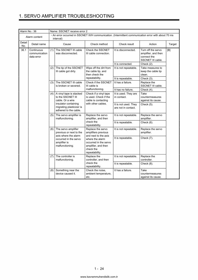
Alarm No.: 36 Name: SSCNET receive error 2
Alarm content An error occurred in SSCNET III/H communication. (Intermittent communication error with about 70 ms interval)
Detail No.
Detail name Cause Check method Check result Action Target
36.1 Continuous communication data error
(1) The SSCNET III cable was disconnected.
Check the SSCNET III cable connection.
It is disconnected. Turn off the servo amplifier, and then connect the SSCNET III cable.
[B]
It is connected. Check (2).
(2) The tip of the SSCNET III cable got dirty.
Wipe off the dirt from the cable tip, and then check the repeatability.
It is not repeatable. Take measures to keep the cable tip clean.
It is repeatable. Check (3).
(3) The SSCNET III cable is broken or severed.
Check if the SSCNET III cable is malfunctioning.
It has a failure. Replace the SSCNET III cable.
It has no failure. Check (4).
(4) A vinyl tape is stacked to the SSCNET III cable. Or a wire insulator containing migrating plasticizer is adhered to the cable.
Check if a vinyl tape is used. Check if the cable is contacting with other cables.
It is used. They are in contact.
Take countermeasures against its cause.
It is not used. They are not in contact.
Check (5).
(5) The servo amplifier is malfunctioning.
Replace the servo amplifier, and then check the repeatability.
It is not repeatable. Replace the servo amplifier.
It is repeatable. Check (6).
(6) The servo amplifier previous or next to the axis where the alarm occurred in the servo amplifier is malfunctioning.
Replace the servo amplifiers previous and next to the axis where the alarm occurred in the servo amplifier, and then check the repeatability.
It is not repeatable. Replace the servo amplifier.
It is repeatable. Check (7).
(7) The controller is malfunctioning.
Replace the controller, and then check the repeatability.
It is not repeatable. Replace the controller.
It is repeatable. Check (8).
(8) Something near the device caused it.
Check the noise, ambient temperature, etc.
It has a failure. Take countermeasures against its cause.
www.kavrammuhendislik.com.tr
1. SERVO AMPLIFIER TROUBLESHOOTING
1 - 25
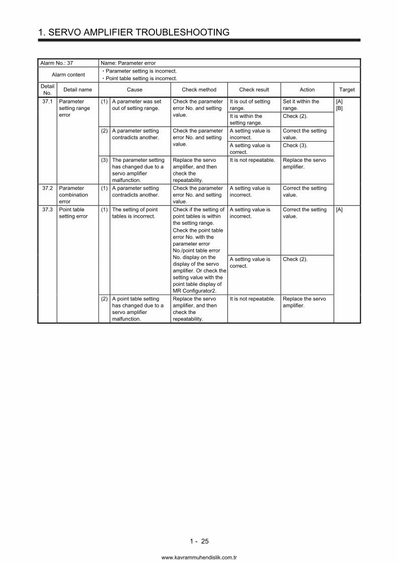
Alarm No.: 37 Name: Parameter error
Alarm content Parameter setting is incorrect. Point table setting is incorrect.
Detail No.
Detail name Cause Check method Check result Action Target
37.1 Parameter setting range error
(1) A parameter was set out of setting range.
Check the parameter error No. and setting value.
It is out of setting range.
Set it within the range.
[A] [B]
It is within the setting range.
Check (2).
(2) A parameter setting contradicts another.
Check the parameter error No. and setting value.
A setting value is incorrect.
Correct the setting value.
A setting value is correct.
Check (3).
(3) The parameter setting has changed due to a servo amplifier malfunction.
Replace the servo amplifier, and then check the repeatability.
It is not repeatable. Replace the servo amplifier.
37.2 Parameter combination error
(1) A parameter setting contradicts another.
Check the parameter error No. and setting value.
A setting value is incorrect.
Correct the setting value.
37.3 Point table setting error
(1) The setting of point tables is incorrect.
Check if the setting of point tables is within the setting range. Check the point table error No. with the parameter error No./point table error No. display on the display of the servo amplifier. Or check the setting value with the point table display of MR Configurator2.
A setting value is incorrect.
Correct the setting value.
[A]
A setting value is correct.
Check (2).
(2) A point table setting has changed due to a servo amplifier malfunction.
Replace the servo amplifier, and then check the repeatability.
It is not repeatable. Replace the servo amplifier.
www.kavrammuhendislik.com.tr
1. SERVO AMPLIFIER TROUBLESHOOTING
1 - 26
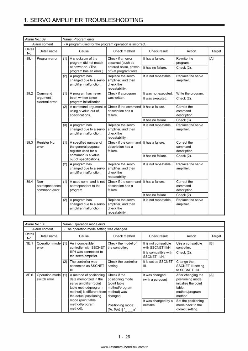
Alarm No.: 39 Name: Program error
Alarm content A program used for the program operation is incorrect.
Detail No.
Detail name Cause Check method Check result Action Target
39.1 Program error (1) A checksum of the program did not match at power-on. (The program has an error.)
Check if an error occurred (such as entered noise, power-off) at program write.
It has a failure. Rewrite the program.
[A]
It has no failure. Check (2).
(2) A program has changed due to a servo amplifier malfunction.
Replace the servo amplifier, and then check the repeatability.
It is not repeatable. Replace the servo amplifier.
39.2 Command argument external error
(1) A program has never been written since program initialization.
Check if a program was written.
It was not executed. Write the program.
It was executed. Check (2).
(2) A command argument is using a value out of specifications.
Check if the command description has a failure.
It has a failure. Correct the command description.
It has no failure. Check (3).
(3) A program has changed due to a servo amplifier malfunction.
Replace the servo amplifier, and then check the repeatability.
It is not repeatable. Replace the servo amplifier.
39.3 Register No. error
(1) A specified number of the general purpose register used for a command is a value out of specifications.
Check if the command description has a failure.
It has a failure. Correct the command description.
It has no failure. Check (2).
(2) A program has changed due to a servo amplifier malfunction.
Replace the servo amplifier, and then check the repeatability.
It is not repeatable. Replace the servo amplifier.
39.4 Non-correspondence command error
(1) A used command is not correspondent to the program.
Check if the command description has a failure.
It has a failure. Correct the command description.
It has no failure. Check (2).
(2) A program has changed due to a servo amplifier malfunction.
Replace the servo amplifier, and then check the repeatability.
It is not repeatable. Replace the servo amplifier.
Alarm No.: 3E Name: Operation mode error
Alarm content The operation mode setting was changed.
Detail No.
Detail name Cause Check method Check result Action Target
3E.1 Operation mode error
(1) An incompatible controller with SSCNET III/H was connected to the servo amplifier.
Check the model of the controller.
It is not compatible with SSCNET III/H.
Use a compatible controller.
[B]
It is compatible with SSCNET III/H.
Check (2).
(2) The controller was connected as SSCNET III.
Check the controller setting.
It is set as SSCNET III.
Change the SSCNET III setting to SSCNET III/H.
3E.6 Operation mode switch error
(1) A method of positioning data memorized in the servo amplifier (point table method/program method) is different from the actual positioning mode (point table method/program method).
Check if the positioning mode (point table method/program method) was changed. Positioning mode: [Pr. PA01] "_ _ _ x"
It was changed. (with a purpose)
After changing the positioning mode, initialize the point table method/program method.
[A]
It was changed by a mistake.
Set the positioning mode back to the correct setting.
www.kavrammuhendislik.com.tr
1. SERVO AMPLIFIER TROUBLESHOOTING
1 - 27
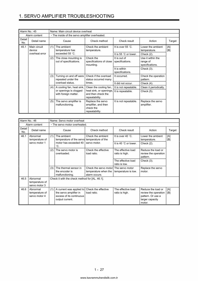
Alarm No.: 45 Name: Main circuit device overheat
Alarm content The inside of the servo amplifier overheated.
Detail No.
Detail name Cause Check method Check result Action Target
45.1 Main circuit device overheat error
(1) The ambient temperature has exceeded 55 ˚C.
Check the ambient temperature.
It is over 55 ˚C. Lower the ambient temperature.
[A] [B]
It is 55 ˚C or lower. Check (2).
(2) The close mounting is out of specifications.
Check the specifications of close mounting.
It is out of specifications.
Use it within the range of specifications.
It is within specifications.
Check (3).
(3) Turning on and off were repeated under the overload status.
Check if the overload status occurred many times.
It occurred. Check the operation pattern.
It did not occur. Check (4).
(4) A cooling fan, heat sink, or openings is clogged with foreign matter.
Clean the cooling fan, heat sink, or openings, and then check the repeatability.
It is not repeatable. Clean it periodically.
It is repeatable. Check (5).
(5) The servo amplifier is malfunctioning.
Replace the servo amplifier, and then check the repeatability.
It is not repeatable. Replace the servo amplifier.
Alarm No.: 46 Name: Servo motor overheat
Alarm content The servo motor overheated.
Detail No.
Detail name Cause Check method Check result Action Target
46.1 Abnormal temperature of servo motor 1
(1) The ambient temperature of the servo motor has exceeded 40 ˚C.
Check the ambient temperature of the servo motor.
It is over 40 ˚C. Lower the ambient temperature.
[A] [B]
It is 40 ˚C or lower. Check (2).
(2) The servo motor is overloaded.
Check the effective load ratio.
The effective load ratio is high.
Reduce the load or review the operation pattern.
The effective load ratio is low.
Check (3).
(3) The thermal sensor in the encoder is malfunctioning.
Check the servo motor temperature when the alarm occurs.
The servo motor temperature is low.
Replace the servo motor.
46.5 Abnormal temperature of servo motor 3
Check it with the check method for [AL. 46.1].
46.6 Abnormal temperature of servo motor 4
(1) A current was applied to the servo amplifier in excess of its continuous output current.
Check the effective load ratio.
The effective load ratio is high.
Reduce the load or review the operation pattern. Or use a larger capacity motor.
[A] [B]
www.kavrammuhendislik.com.tr
1. SERVO AMPLIFIER TROUBLESHOOTING
1 - 28
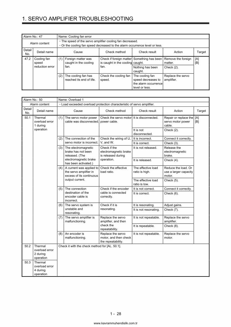
Alarm No.: 47 Name: Cooling fan error
Alarm content The speed of the servo amplifier cooling fan decreased. Or the cooling fan speed decreased to the alarm occurrence level or less.
Detail No.
Detail name Cause Check method Check result Action Target
47.2 Cooling fan speed reduction error
(1) Foreign matter was caught in the cooling fan.
Check if foreign matter is caught in the cooling fan.
Something has been caught.
Remove the foreign matter.
[A] [B]
Nothing has been caught.
Check (2).
(2) The cooling fan has reached its end of life.
Check the cooling fan speed.
The cooling fan speed decreases to the alarm occurrence level or less.
Replace the servo amplifier.
Alarm No.: 50 Name: Overload 1
Alarm content Load exceeded overload protection characteristic of servo amplifier.
Detail No.
Detail name Cause Check method Check result Action Target
50.1 Thermal overload error 1 during operation
(1) The servo motor power cable was disconnected.
Check the servo motor power cable.
It is disconnected. Repair or replace the servo motor power cable.
[A] [B]
It is not disconnected.
Check (2).
(2) The connection of the servo motor is incorrect.
Check the wiring of U, V, and W.
It is incorrect. Connect it correctly.
It is correct. Check (3).
(3) The electromagnetic brake has not been released. (The electromagnetic brake has been activated.)
Check if the electromagnetic brake is released during operation.
It is not released. Release the electromagnetic brake.
It is released. Check (4).
(4) A current was applied to the servo amplifier in excess of its continuous output current.
Check the effective load ratio.
The effective load ratio is high.
Reduce the load. Or use a larger capacity motor.
The effective load ratio is low.
Check (5).
(5) The connection destination of the encoder cable is incorrect.
Check if the encoder cable is connected correctly.
It is not correct. Connect it correctly.
It is correct. Check (6).
(6) The servo system is unstable and resonating.
Check if it is resonating.
It is resonating. Adjust gains.
It is not resonating. Check (7).
(7) The servo amplifier is malfunctioning.
Replace the servo amplifier, and then check the repeatability.
It is not repeatable. Replace the servo amplifier.
It is repeatable. Check (8).
(8) An encoder is malfunctioning.
Replace the servo motor, and then check the repeatability.
It is not repeatable. Replace the servo motor.
50.2 Thermal overload error 2 during operation
Check it with the check method for [AL. 50.1].
50.3 Thermal overload error 4 during operation
www.kavrammuhendislik.com.tr
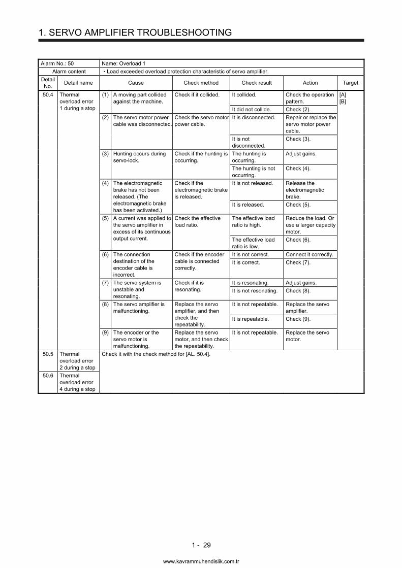
1. SERVO AMPLIFIER TROUBLESHOOTING
1 - 29
Alarm No.: 50 Name: Overload 1
Alarm content Load exceeded overload protection characteristic of servo amplifier.
Detail No.
Detail name Cause Check method Check result Action Target
50.4 Thermal overload error 1 during a stop
(1) A moving part collided against the machine.
Check if it collided. It collided. Check the operation pattern.
[A] [B]
It did not collide. Check (2).
(2) The servo motor power cable was disconnected.
Check the servo motor power cable.
It is disconnected. Repair or replace the servo motor power cable.
It is not disconnected.
Check (3).
(3) Hunting occurs during servo-lock.
Check if the hunting is occurring.
The hunting is occurring.
Adjust gains.
The hunting is not occurring.
Check (4).
(4) The electromagnetic brake has not been released. (The electromagnetic brake has been activated.)
Check if the electromagnetic brake is released.
It is not released. Release the electromagnetic brake.
It is released. Check (5).
(5) A current was applied to the servo amplifier in excess of its continuous output current.
Check the effective load ratio.
The effective load ratio is high.
Reduce the load. Or use a larger capacity motor.
The effective load ratio is low.
Check (6).
(6) The connection destination of the encoder cable is incorrect.
Check if the encoder cable is connected correctly.
It is not correct. Connect it correctly.
It is correct. Check (7).
(7) The servo system is unstable and resonating.
Check if it is resonating.
It is resonating. Adjust gains.
It is not resonating. Check (8).
(8) The servo amplifier is malfunctioning.
Replace the servo amplifier, and then check the repeatability.
It is not repeatable. Replace the servo amplifier.
It is repeatable. Check (9).
(9) The encoder or the servo motor is malfunctioning.
Replace the servo motor, and then check the repeatability.
It is not repeatable. Replace the servo motor.
50.5 Thermal overload error 2 during a stop
Check it with the check method for [AL. 50.4].
50.6 Thermal overload error 4 during a stop
www.kavrammuhendislik.com.tr
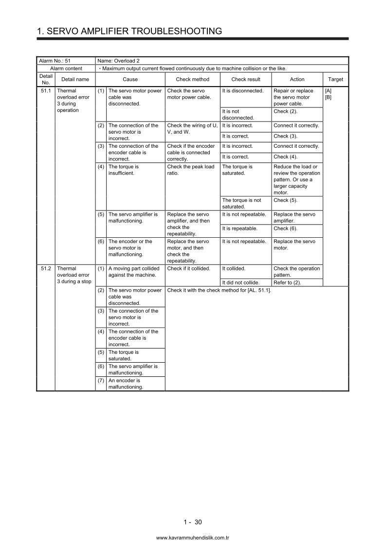
1. SERVO AMPLIFIER TROUBLESHOOTING
1 - 30
Alarm No.: 51 Name: Overload 2
Alarm content Maximum output current flowed continuously due to machine collision or the like.
Detail No.
Detail name Cause Check method Check result Action Target
51.1 Thermal overload error 3 during operation
(1) The servo motor power cable was disconnected.
Check the servo motor power cable.
It is disconnected. Repair or replace the servo motor power cable.
[A] [B]
It is not disconnected.
Check (2).
(2) The connection of the servo motor is incorrect.
Check the wiring of U, V, and W.
It is incorrect. Connect it correctly.
It is correct. Check (3).
(3) The connection of the encoder cable is incorrect.
Check if the encoder cable is connected correctly.
It is incorrect. Connect it correctly.
It is correct. Check (4).
(4) The torque is insufficient.
Check the peak load ratio.
The torque is saturated.
Reduce the load or review the operation pattern. Or use a larger capacity motor.
The torque is not saturated.
Check (5).
(5) The servo amplifier is malfunctioning.
Replace the servo amplifier, and then check the repeatability.
It is not repeatable. Replace the servo amplifier.
It is repeatable. Check (6).
(6) The encoder or the servo motor is malfunctioning.
Replace the servo motor, and then check the repeatability.
It is not repeatable. Replace the servo motor.
51.2 Thermal overload error 3 during a stop
(1) A moving part collided against the machine.
Check if it collided. It collided. Check the operation pattern.
It did not collide. Refer to (2).
(2) The servo motor power cable was disconnected.
Check it with the check method for [AL. 51.1].
(3) The connection of the servo motor is incorrect.
(4) The connection of the encoder cable is incorrect.
(5) The torque is saturated.
(6) The servo amplifier is malfunctioning.
(7) An encoder is malfunctioning.
www.kavrammuhendislik.com.tr
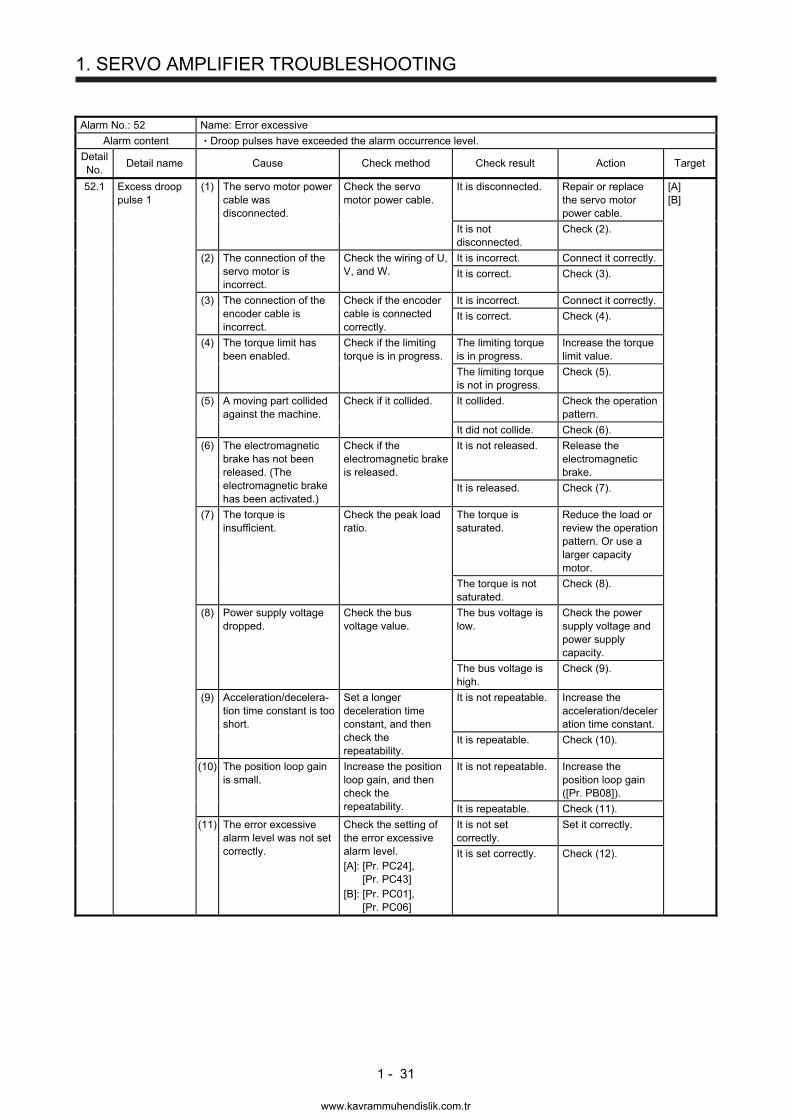
1. SERVO AMPLIFIER TROUBLESHOOTING
1 - 31
Alarm No.: 52 Name: Error excessive
Alarm content Droop pulses have exceeded the alarm occurrence level.
Detail No.
Detail name Cause Check method Check result Action Target
52.1 Excess droop pulse 1
(1) The servo motor power cable was disconnected.
Check the servo motor power cable.
It is disconnected. Repair or replace the servo motor power cable.
[A] [B]
It is not disconnected.
Check (2).
(2) The connection of the servo motor is incorrect.
Check the wiring of U, V, and W.
It is incorrect. Connect it correctly.
It is correct. Check (3).
(3) The connection of the encoder cable is incorrect.
Check if the encoder cable is connected correctly.
It is incorrect. Connect it correctly.
It is correct. Check (4).
(4) The torque limit has been enabled.
Check if the limiting torque is in progress.
The limiting torque is in progress.
Increase the torque limit value.
The limiting torque is not in progress.
Check (5).
(5) A moving part collided against the machine.
Check if it collided. It collided. Check the operation pattern.
It did not collide. Check (6).
(6) The electromagnetic brake has not been released. (The electromagnetic brake has been activated.)
Check if the electromagnetic brake is released.
It is not released. Release the electromagnetic brake.
It is released. Check (7).
(7) The torque is insufficient.
Check the peak load ratio.
The torque is saturated.
Reduce the load or review the operation pattern. Or use a larger capacity motor.
The torque is not saturated.
Check (8).
(8) Power supply voltage dropped.
Check the bus voltage value.
The bus voltage is low.
Check the power supply voltage and power supply capacity.
The bus voltage is high.
Check (9).
(9) Acceleration/decelera-tion time constant is too short.
Set a longer deceleration time constant, and then check the repeatability.
It is not repeatable. Increase the acceleration/deceleration time constant.
It is repeatable. Check (10).
(10) The position loop gain is small.
Increase the position loop gain, and then check the repeatability.
It is not repeatable. Increase the position loop gain ([Pr. PB08]).
It is repeatable. Check (11).
(11) The error excessive alarm level was not set correctly.
Check the setting of the error excessive alarm level. [A]: [Pr. PC24],
[Pr. PC43] [B]: [Pr. PC01],
[Pr. PC06]
It is not set correctly.
Set it correctly.
It is set correctly. Check (12).
www.kavrammuhendislik.com.tr
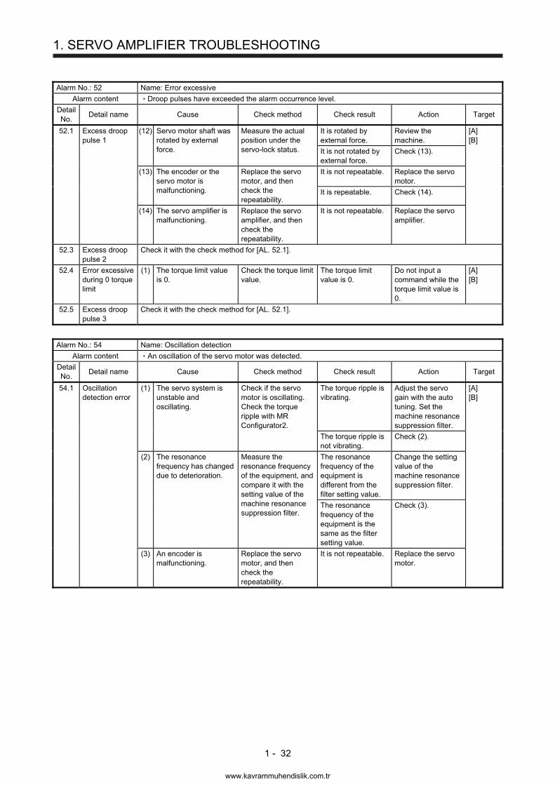
1. SERVO AMPLIFIER TROUBLESHOOTING
1 - 32
Alarm No.: 52 Name: Error excessive
Alarm content Droop pulses have exceeded the alarm occurrence level.
Detail No.
Detail name Cause Check method Check result Action Target
52.1 Excess droop pulse 1
(12) Servo motor shaft was rotated by external force.
Measure the actual position under the servo-lock status.
It is rotated by external force.
Review the machine.
[A] [B]
It is not rotated by external force.
Check (13).
(13) The encoder or the servo motor is malfunctioning.
Replace the servo motor, and then check the repeatability.
It is not repeatable. Replace the servo motor.
It is repeatable. Check (14).
(14) The servo amplifier is malfunctioning.
Replace the servo amplifier, and then check the repeatability.
It is not repeatable. Replace the servo amplifier.
52.3 Excess droop pulse 2
Check it with the check method for [AL. 52.1].
52.4 Error excessive during 0 torque limit
(1) The torque limit value is 0.
Check the torque limit value.
The torque limit value is 0.
Do not input a command while the torque limit value is 0.
[A] [B]
52.5 Excess droop pulse 3
Check it with the check method for [AL. 52.1].
Alarm No.: 54 Name: Oscillation detection
Alarm content An oscillation of the servo motor was detected.
Detail No.
Detail name Cause Check method Check result Action Target
54.1 Oscillation detection error
(1) The servo system is unstable and oscillating.
Check if the servo motor is oscillating. Check the torque ripple with MR Configurator2.
The torque ripple is vibrating.
Adjust the servo gain with the auto tuning. Set the machine resonance suppression filter.
[A] [B]
The torque ripple is not vibrating.
Check (2).
(2) The resonance frequency has changed due to deterioration.
Measure the resonance frequency of the equipment, and compare it with the setting value of the machine resonance suppression filter.
The resonance frequency of the equipment is different from the filter setting value.
Change the setting value of the machine resonance suppression filter.
The resonance frequency of the equipment is the same as the filter setting value.
Check (3).
(3) An encoder is malfunctioning.
Replace the servo motor, and then check the repeatability.
It is not repeatable. Replace the servo motor.
www.kavrammuhendislik.com.tr
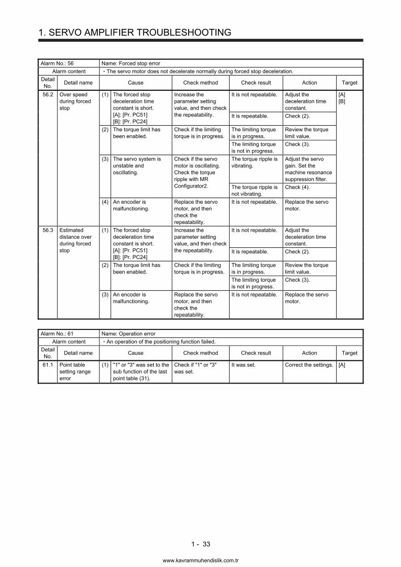
1. SERVO AMPLIFIER TROUBLESHOOTING
1 - 33
Alarm No.: 56 Name: Forced stop error
Alarm content The servo motor does not decelerate normally during forced stop deceleration.
Detail No.
Detail name Cause Check method Check result Action Target
56.2 Over speed during forced stop
(1) The forced stop deceleration time constant is short. [A]: [Pr. PC51] [B]: [Pr. PC24]
Increase the parameter setting value, and then check the repeatability.
It is not repeatable. Adjust the deceleration time constant.
[A] [B]
It is repeatable. Check (2).
(2) The torque limit has been enabled.
Check if the limiting torque is in progress.
The limiting torque is in progress.
Review the torque limit value.
The limiting torque is not in progress.
Check (3).
(3) The servo system is unstable and oscillating.
Check if the servo motor is oscillating. Check the torque ripple with MR Configurator2.
The torque ripple is vibrating.
Adjust the servo gain. Set the machine resonance suppression filter.
The torque ripple is not vibrating.
Check (4).
(4) An encoder is malfunctioning.
Replace the servo motor, and then check the repeatability.
It is not repeatable. Replace the servo motor.
56.3 Estimated distance over during forced stop
(1) The forced stop deceleration time constant is short. [A]: [Pr. PC51] [B]: [Pr. PC24]
Increase the parameter setting value, and then check the repeatability.
It is not repeatable. Adjust the deceleration time constant.
It is repeatable. Check (2).
(2) The torque limit has been enabled.
Check if the limiting torque is in progress.
The limiting torque is in progress.
Review the torque limit value.
The limiting torque is not in progress.
Check (3).
(3) An encoder is malfunctioning.
Replace the servo motor, and then check the repeatability.
It is not repeatable. Replace the servo motor.
Alarm No.: 61 Name: Operation error
Alarm content An operation of the positioning function failed.
Detail No.
Detail name Cause Check method Check result Action Target
61.1 Point table setting range error
(1) "1" or "3" was set to the sub function of the last point table (31).
Check if "1" or "3" was set.
It was set. Correct the settings. [A]
www.kavrammuhendislik.com.tr
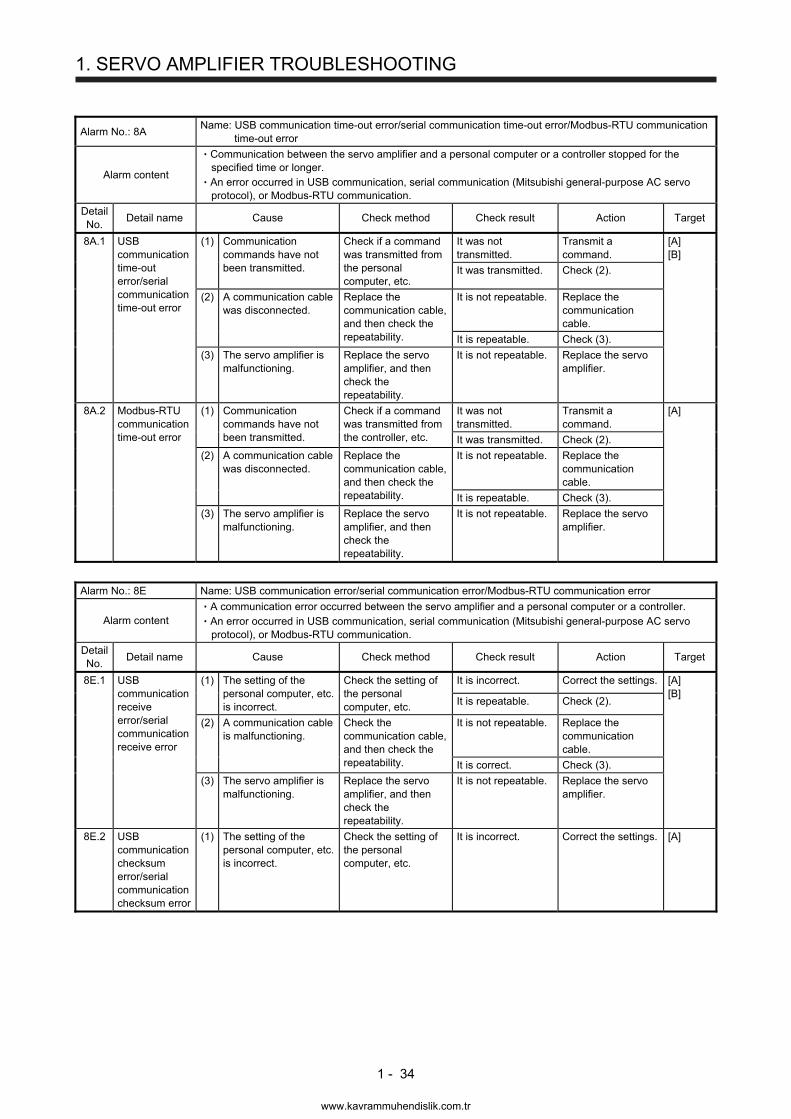
1. SERVO AMPLIFIER TROUBLESHOOTING
1 - 34
Alarm No.: 8A Name: USB communication time-out error/serial communication time-out error/Modbus-RTU communication
time-out error
Alarm content
Communication between the servo amplifier and a personal computer or a controller stopped for the specified time or longer. An error occurred in USB communication, serial communication (Mitsubishi general-purpose AC servo protocol), or Modbus-RTU communication.
Detail No.
Detail name Cause Check method Check result Action Target
8A.1 USB communication time-out error/serial communication time-out error
(1) Communication commands have not been transmitted.
Check if a command was transmitted from the personal computer, etc.
It was not transmitted.
Transmit a command.
[A] [B]
It was transmitted. Check (2).
(2) A communication cable was disconnected.
Replace the communication cable, and then check the repeatability.
It is not repeatable. Replace the communication cable.
It is repeatable. Check (3).
(3) The servo amplifier is malfunctioning.
Replace the servo amplifier, and then check the repeatability.
It is not repeatable. Replace the servo amplifier.
8A.2 Modbus-RTU communication time-out error
(1) Communication commands have not been transmitted.
Check if a command was transmitted from the controller, etc.
It was not transmitted.
Transmit a command.
[A]
It was transmitted. Check (2).
(2) A communication cable was disconnected.
Replace the communication cable, and then check the repeatability.
It is not repeatable. Replace the communication cable.
It is repeatable. Check (3).
(3) The servo amplifier is malfunctioning.
Replace the servo amplifier, and then check the repeatability.
It is not repeatable. Replace the servo amplifier.
Alarm No.: 8E Name: USB communication error/serial communication error/Modbus-RTU communication error
Alarm content A communication error occurred between the servo amplifier and a personal computer or a controller. An error occurred in USB communication, serial communication (Mitsubishi general-purpose AC servo protocol), or Modbus-RTU communication.
Detail No.
Detail name Cause Check method Check result Action Target
8E.1 USB communication receive error/serial communication receive error
(1) The setting of the personal computer, etc. is incorrect.
Check the setting of the personal computer, etc.
It is incorrect. Correct the settings. [A] [B]
It is repeatable. Check (2).
(2) A communication cable is malfunctioning.
Check the communication cable, and then check the repeatability.
It is not repeatable. Replace the communication cable.
It is correct. Check (3).
(3) The servo amplifier is malfunctioning.
Replace the servo amplifier, and then check the repeatability.
It is not repeatable. Replace the servo amplifier.
8E.2 USB communication checksum error/serial communication checksum error
(1) The setting of the personal computer, etc. is incorrect.
Check the setting of the personal computer, etc.
It is incorrect. Correct the settings. [A]
www.kavrammuhendislik.com.tr
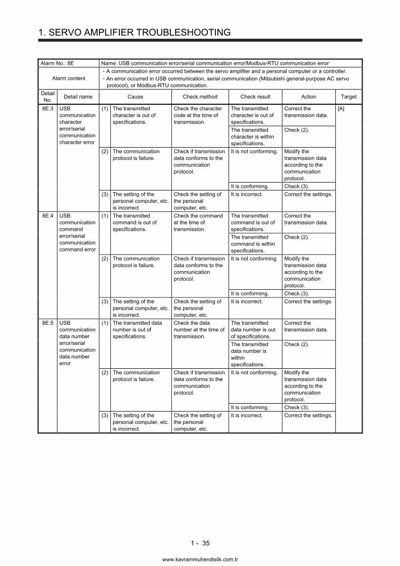
1. SERVO AMPLIFIER TROUBLESHOOTING
1 - 35
Alarm No.: 8E Name: USB communication error/serial communication error/Modbus-RTU communication error
Alarm content A communication error occurred between the servo amplifier and a personal computer or a controller. An error occurred in USB communication, serial communication (Mitsubishi general-purpose AC servo protocol), or Modbus-RTU communication.
Detail No.
Detail name Cause Check method Check result Action Target
8E.3 USB communication character error/serial communication character error
(1) The transmitted character is out of specifications.
Check the character code at the time of transmission.
The transmitted character is out of specifications.
Correct the transmission data.
[A]
The transmitted character is within specifications.
Check (2).
(2) The communication protocol is failure.
Check if transmission data conforms to the communication protocol.
It is not conforming. Modify the transmission data according to the communication protocol.
It is conforming. Check (3).
(3) The setting of the personal computer, etc. is incorrect.
Check the setting of the personal computer, etc.
It is incorrect. Correct the settings.
8E.4 USB communication command error/serial communication command error
(1) The transmitted command is out of specifications.
Check the command at the time of transmission.
The transmitted command is out of specifications.
Correct the transmission data.
The transmitted command is within specifications.
Check (2).
(2) The communication protocol is failure.
Check if transmission data conforms to the communication protocol.
It is not conforming. Modify the transmission data according to the communication protocol.
It is conforming. Check (3).
(3) The setting of the personal computer, etc. is incorrect.
Check the setting of the personal computer, etc.
It is incorrect. Correct the settings.
8E.5 USB communication data number error/serial communication data number error
(1) The transmitted data number is out of specifications.
Check the data number at the time of transmission.
The transmitted data number is out of specifications.
Correct the transmission data.
The transmitted data number is within specifications.
Check (2).
(2) The communication protocol is failure.
Check if transmission data conforms to the communication protocol.
It is not conforming. Modify the transmission data according to the communication protocol.
It is conforming. Check (3).
(3) The setting of the personal computer, etc. is incorrect.
Check the setting of the personal computer, etc.
It is incorrect. Correct the settings.
www.kavrammuhendislik.com.tr
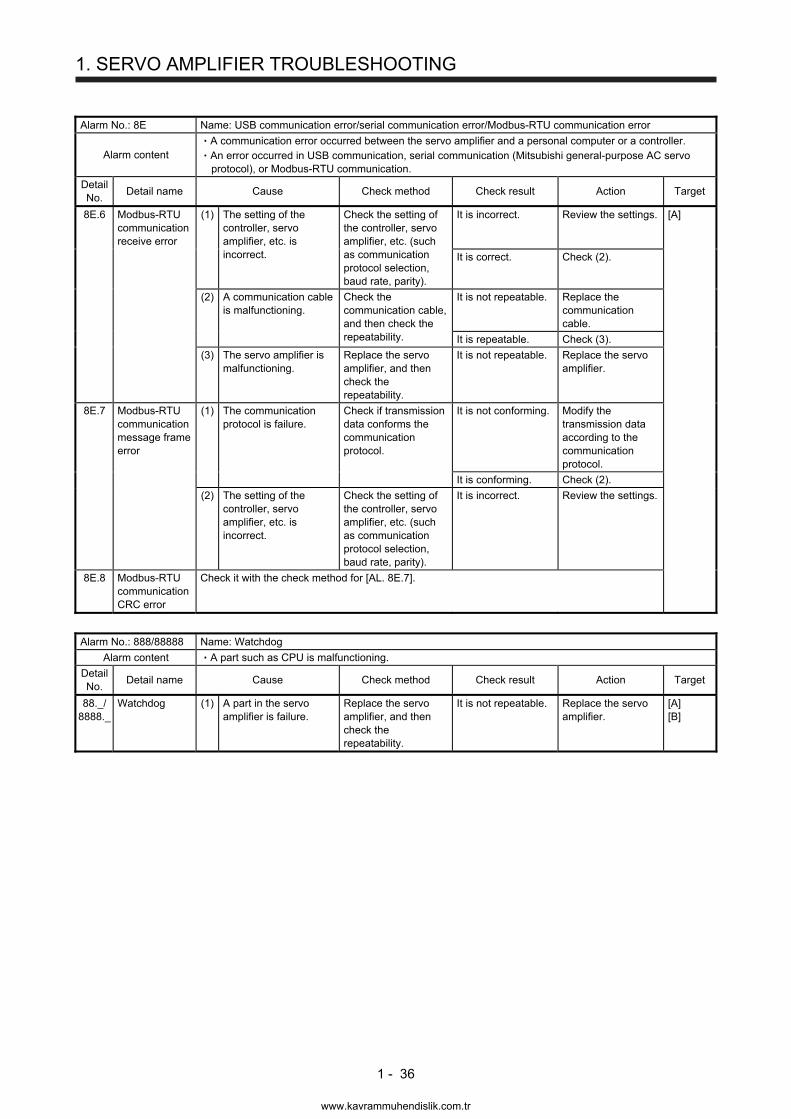
1. SERVO AMPLIFIER TROUBLESHOOTING
1 - 36
Alarm No.: 8E Name: USB communication error/serial communication error/Modbus-RTU communication error
Alarm content A communication error occurred between the servo amplifier and a personal computer or a controller. An error occurred in USB communication, serial communication (Mitsubishi general-purpose AC servo protocol), or Modbus-RTU communication.
Detail No.
Detail name Cause Check method Check result Action Target
8E.6 Modbus-RTU communication receive error
(1) The setting of the controller, servo amplifier, etc. is incorrect.
Check the setting of the controller, servo amplifier, etc. (such as communication protocol selection, baud rate, parity).
It is incorrect. Review the settings. [A]
It is correct. Check (2).
(2) A communication cable is malfunctioning.
Check the communication cable, and then check the repeatability.
It is not repeatable. Replace the communication cable.
It is repeatable. Check (3).
(3) The servo amplifier is malfunctioning.
Replace the servo amplifier, and then check the repeatability.
It is not repeatable. Replace the servo amplifier.
8E.7 Modbus-RTU communication message frame error
(1) The communication protocol is failure.
Check if transmission data conforms the communication protocol.
It is not conforming. Modify the transmission data according to the communication protocol.
It is conforming. Check (2).
(2) The setting of the controller, servo amplifier, etc. is incorrect.
Check the setting of the controller, servo amplifier, etc. (such as communication protocol selection, baud rate, parity).
It is incorrect. Review the settings.
8E.8 Modbus-RTU communication CRC error
Check it with the check method for [AL. 8E.7].
Alarm No.: 888/88888 Name: Watchdog
Alarm content A part such as CPU is malfunctioning.
Detail No.
Detail name Cause Check method Check result Action Target
88._/ 8888._
Watchdog (1) A part in the servo amplifier is failure.
Replace the servo amplifier, and then check the repeatability.
It is not repeatable. Replace the servo amplifier.
[A] [B]
www.kavrammuhendislik.com.tr
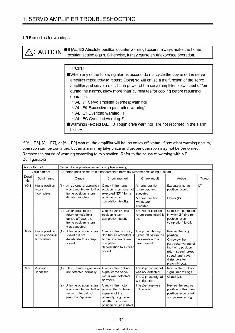
1. SERVO AMPLIFIER TROUBLESHOOTING
1 - 37
1.5 Remedies for warnings
CAUTION If [AL. E3 Absolute position counter warning] occurs, always make the home position setting again. Otherwise, it may cause an unexpected operation.
POINT
When any of the following alarms occurs, do not cycle the power of the servo amplifier repeatedly to restart. Doing so will cause a malfunction of the servo amplifier and servo motor. If the power of the servo amplifier is switched off/on during the alarms, allow more than 30 minutes for cooling before resuming operation.
[AL. 91 Servo amplifier overheat warning]
[AL. E0 Excessive regeneration warning]
[AL. E1 Overload warning 1]
[AL. EC Overload warning 2]
Warnings (except [AL. F0 Tough drive warning]) are not recorded in the alarm history.
If [AL. E6], [AL. E7], or [AL. E9] occurs, the amplifier will be the servo-off status. If any other warning occurs, operation can be continued but an alarm may take place and proper operation may not be performed. Remove the cause of warning according to this section. Refer to the cause of warning with MR Configurator2. Alarm No.: 90 Name: Home position return incomplete warning
Alarm content A home position return did not complete normally with the positioning function.
Detail No.
Detail name Cause Check method Check result Action Target
90.1 Home position return incomplete
(1) An automatic operation was executed while the home position return did not complete.
Check if the home position return was not executed (ZP (Home position return completion) is off.).
A home position return was not executed.
Execute a home position return.
[A]
A home position return was executed.
Check (2).
(2) ZP (Home position return completion) turned off after the home position return was executed.
Check if ZP (Home position return completion) is off.
ZP (Home position return completion) is off.
Check the conditions in which ZP (Home position return completion) is off.
90.2 Home position return abnormal termination
(1) A home position return speed did not decelerate to a creep speed.
Check if the proximity dog turned off before a home position return completed deceleration to a creep speed.
The proximity dog turned off before the deceleration to a creep speed.
Review the dog position. Or review the parameter values of the home position return speed, creep speed, and travel distance after proximity dog.
90.5 Z-phase unpassed
(1) The Z-phase signal was not detected normally.
Check if the Z-phase signal of the servo motor was detected normally.
The Z-phase signal was not detected.
Review the Z-phase signal and wirings.
The Z-phase signal was detected.
Check (2).
(2) A home position return was executed while the servo motor did not pass the Z-phase.
Check if the motor passed the Z-phase signal until the proximity dog turned off after the home position return started.
The Z-phase was not passed.
Review the setting position of the home position return start and proximity dog.
www.kavrammuhendislik.com.tr
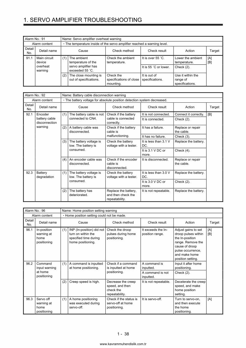
1. SERVO AMPLIFIER TROUBLESHOOTING
1 - 38
Alarm No.: 91 Name: Servo amplifier overheat warning
Alarm content The temperature inside of the servo amplifier reached a warning level.
Detail No.
Detail name Cause Check method Check result Action Target
91.1 Main circuit device overheat warning
(1) The ambient temperature of the servo amplifier has exceeded 55 ˚C.
Check the ambient temperature.
It is over 55 ˚C. Lower the ambient temperature.
[A] [B]
It is 55 ˚C or lower. Check (2).
(2) The close mounting is out of specifications.
Check the specifications of close mounting.
It is out of specifications.
Use it within the range of specifications.
Alarm No.: 92 Name: Battery cable disconnection warning
Alarm content The battery voltage for absolute position detection system decreased.
Detail No.
Detail name Cause Check method Check result Action Target
92.1 Encoder battery cable disconnection warning
(1) The battery cable is not connected to CN4.
Check if the battery cable is connected correctly.
It is not connected. Connect it correctly. [B]
It is connected. Check (2).
(2) A battery cable was disconnected.
Check if the battery cable is malfunctioning.
It has a failure. Replace or repair the cable.
It has no failure. Check (3).
(3) The battery voltage is low. The battery is consumed.
Check the battery voltage with a tester.
It is less than 3.1 V DC.
Replace the battery.
It is 3.1 V DC or more.
Check (4).
(4) An encoder cable was disconnected.
Check if the encoder cable is disconnected.
It is disconnected. Replace or repair the cable.
92.3 Battery degradation
(1) The battery voltage is low. The battery is consumed.
Check the battery voltage with a tester.
It is less than 3.0 V DC.
Replace the battery.
It is 3.0 V DC or more.
Check (2).
(2) The battery has deteriorated.
Replace the battery, and then check the repeatability.
It is not repeatable. Replace the battery.
Alarm No.: 96 Name: Home position setting warning
Alarm content Home position setting could not be made.
Detail No.
Detail name Cause Check method Check result Action Target
96.1 In-position warning at home positioning
(1) INP (In-position) did not turn on within the specified time during home positioning.
Check the droop pulses during home positioning.
It exceeds the In-position range.
Adjust gains to set droop pulses within the In-position range. Remove the cause of droop pulse occurrence, and make home position setting.
[A] [B]
96.2 Command input warning at home positioning
(1) A command is inputted at home positioning.
Check if a command is inputted at home positioning.
A command is inputted.
Input it after home positioning.
A command is not inputted.
Check (2).
(2) Creep speed is high. Decrease the creep speed, and then check the repeatability.
It is not repeatable. Decelerate the creep speed, and make home position setting.
96.3 Servo off warning at home positioning
(1) A home positioning was executed during servo-off.
Check if the status is servo-off at home positioning.
It is servo-off. Turn to servo-on, and then execute the home positioning.
[A]
www.kavrammuhendislik.com.tr
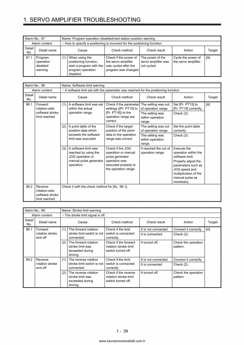
1. SERVO AMPLIFIER TROUBLESHOOTING
1 - 39
Alarm No.: 97 Name: Program operation disabled/next station position warning
Alarm content How to specify a positioning is incorrect for the positioning function.
Detail No.
Detail name Cause Check method Check result Action Target
97.1 Program operation disabled warning
(1) When using the positioning function, start a program with the program operation disabled.
Check if the power of the servo amplifier was cycled after the program was changed.
The power of the servo amplifier was not cycled.
Cycle the power of the servo amplifier.
[A]
Alarm No.: 98 Name: Software limit warning
Alarm content A software limit set with the parameter was reached for the positioning function.
Detail No.
Detail name Cause Check method Check result Action Target
98.1 Forward rotation-side software stroke limit reached
(1) A software limit was set within the actual operation range.
Check if the parameter settings ([Pr. PT15] to [Pr. PT18]) to the operation range are correct.
The setting was out of operation range.
Set [Pr. PT15] to [Pr. PT18] correctly.
[A]
The setting was within operation range.
Check (2).
(2) A point table of the position data which exceeds the software limit was executed.
Check if the target position of the point data to the operation range was correct.
The setting was out of operation range.
Set the point table correctly.
The setting was within operation range.
Check (3).
(3) A software limit was reached by using the JOG operation or manual pulse generator operation.
Check if the JOG operation or manual pulse generator operation was executed properly to the operation range.
It reached the out of operation range.
Execute the operation within the software limit. Properly adjust the parameters such as JOG speed and multiplication of the manual pulse as necessary.
98.2 Reverse rotation-side software stroke limit reached
Check it with the check method for [AL. 98.1].
Alarm No.: 99 Name: Stroke limit warning
Alarm content The stroke limit signal is off.
Detail No.
Detail name Cause Check method Check result Action Target
99.1 Forward rotation stroke end off
(1) The forward rotation stroke limit switch is not connected.
Check if the limit switch is connected correctly.
It is not connected. Connect it correctly. [A]
It is connected. Check (2).
(2) The forward rotation stroke limit was exceeded during driving.
Check if the forward rotation stroke limit switch turned off.
It turned off. Check the operation pattern.
99.2 Reverse rotation stroke end off
(1) The reverse rotation stroke limit switch is not connected.
Check if the limit switch is connected correctly.
It is not connected. Connect it correctly.
It is connected. Check (2).
(2) The reverse rotation stroke limit was exceeded during driving.
Check if the reverse rotation stroke limit switch turned off.
It turned off. Check the operation pattern.
www.kavrammuhendislik.com.tr
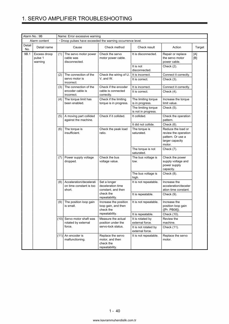
1. SERVO AMPLIFIER TROUBLESHOOTING
1 - 40
Alarm No.: 9B Name: Error excessive warning
Alarm content Droop pulses have exceeded the warning occurrence level.
Detail No.
Detail name Cause Check method Check result Action Target
9B.1 Excess droop pulse 1 warning
(1) The servo motor power cable was disconnected.
Check the servo motor power cable.
It is disconnected. Repair or replace the servo motor power cable.
[A] [B]
It is not disconnected.
Check (2).
(2) The connection of the servo motor is incorrect.
Check the wiring of U, V, and W.
It is incorrect. Connect it correctly.
It is correct. Check (3).
(3) The connection of the encoder cable is incorrect.
Check if the encoder cable is connected correctly.
It is incorrect. Connect it correctly.
It is correct. Check (4).
(4) The torque limit has been enabled.
Check if the limiting torque is in progress.
The limiting torque is in progress.
Increase the torque limit value.
The limiting torque is not in progress.
Check (5).
(5) A moving part collided against the machine.
Check if it collided. It collided. Check the operation pattern.
It did not collide. Check (6).
(6) The torque is insufficient.
Check the peak load ratio.
The torque is saturated.
Reduce the load or review the operation pattern. Or use a larger capacity motor.
The torque is not saturated.
Check (7).
(7) Power supply voltage dropped.
Check the bus voltage value.
The bus voltage is low.
Check the power supply voltage and power supply capacity.
The bus voltage is high.
Check (8).
(8) Acceleration/deceleration time constant is too short.
Set a longer deceleration time constant, and then check the repeatability.
It is not repeatable. Increase the acceleration/deceleration time constant.
It is repeatable. Check (9).
(9) The position loop gain is small.
Increase the position loop gain, and then check the repeatability.
It is not repeatable. Increase the position loop gain ([Pr. PB08]).
It is repeatable. Check (10).
(10) Servo motor shaft was rotated by external force.
Measure the actual position under the servo-lock status.
It is rotated by external force.
Review the machine.
It is not rotated by external force.
Check (11).
(11) An encoder is malfunctioning.
Replace the servo motor, and then check the repeatability.
It is not repeatable. Replace the servo motor.
www.kavrammuhendislik.com.tr
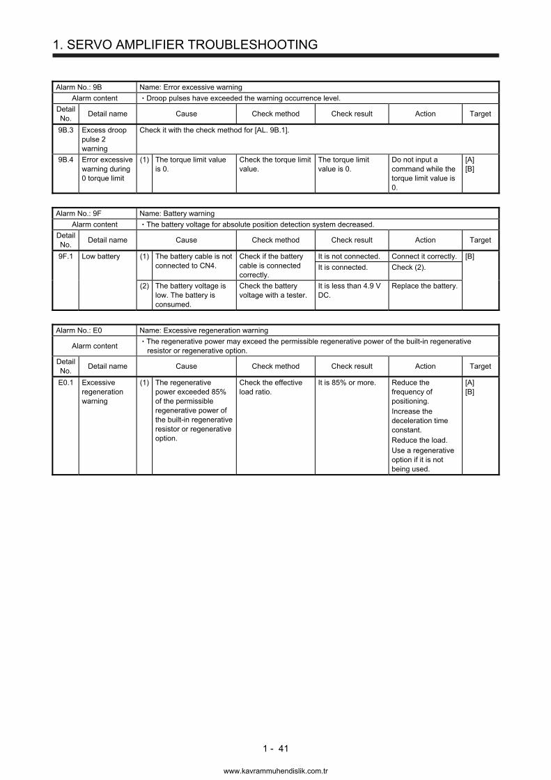
1. SERVO AMPLIFIER TROUBLESHOOTING
1 - 41
Alarm No.: 9B Name: Error excessive warning
Alarm content Droop pulses have exceeded the warning occurrence level.
Detail No.
Detail name Cause Check method Check result Action Target
9B.3 Excess droop pulse 2 warning
Check it with the check method for [AL. 9B.1].
9B.4 Error excessive warning during 0 torque limit
(1) The torque limit value is 0.
Check the torque limit value.
The torque limit value is 0.
Do not input a command while the torque limit value is 0.
[A] [B]
Alarm No.: 9F Name: Battery warning
Alarm content The battery voltage for absolute position detection system decreased.
Detail No.
Detail name Cause Check method Check result Action Target
9F.1 Low battery (1) The battery cable is not connected to CN4.
Check if the battery cable is connected correctly.
It is not connected. Connect it correctly. [B]
It is connected. Check (2).
(2) The battery voltage is low. The battery is consumed.
Check the battery voltage with a tester.
It is less than 4.9 V DC.
Replace the battery.
Alarm No.: E0 Name: Excessive regeneration warning
Alarm content The regenerative power may exceed the permissible regenerative power of the built-in regenerative resistor or regenerative option.
Detail No.
Detail name Cause Check method Check result Action Target
E0.1 Excessive regeneration warning
(1) The regenerative power exceeded 85% of the permissible regenerative power of the built-in regenerative resistor or regenerative option.
Check the effective load ratio.
It is 85% or more. Reduce the frequency of positioning. Increase the deceleration time constant. Reduce the load. Use a regenerative option if it is not being used.
[A] [B]
www.kavrammuhendislik.com.tr
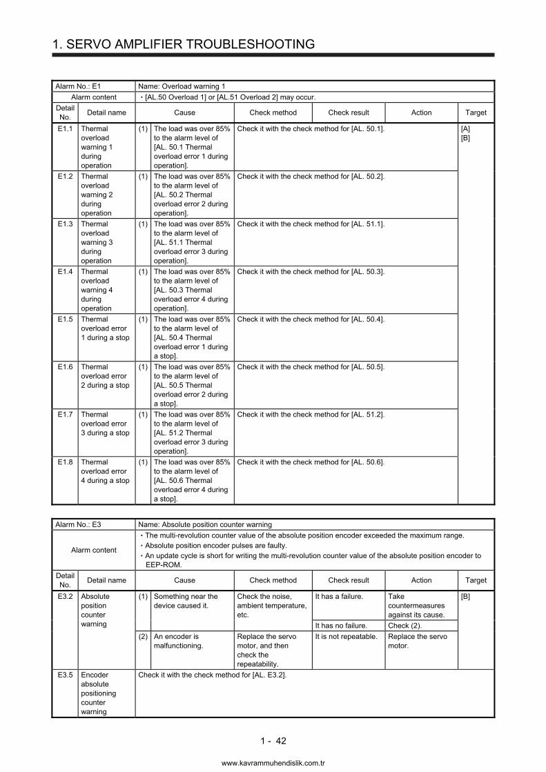
1. SERVO AMPLIFIER TROUBLESHOOTING
1 - 42
Alarm No.: E1 Name: Overload warning 1
Alarm content [AL.50 Overload 1] or [AL.51 Overload 2] may occur.
Detail No.
Detail name Cause Check method Check result Action Target
E1.1 Thermal overload warning 1 during operation
(1) The load was over 85% to the alarm level of [AL. 50.1 Thermal overload error 1 during operation].
Check it with the check method for [AL. 50.1]. [A] [B]
E1.2 Thermal overload warning 2 during operation
(1) The load was over 85% to the alarm level of [AL. 50.2 Thermal overload error 2 during operation].
Check it with the check method for [AL. 50.2].
E1.3 Thermal overload warning 3 during operation
(1) The load was over 85% to the alarm level of [AL. 51.1 Thermal overload error 3 during operation].
Check it with the check method for [AL. 51.1].
E1.4 Thermal overload warning 4 during operation
(1) The load was over 85% to the alarm level of [AL. 50.3 Thermal overload error 4 during operation].
Check it with the check method for [AL. 50.3].
E1.5 Thermal overload error 1 during a stop
(1) The load was over 85% to the alarm level of [AL. 50.4 Thermal overload error 1 during a stop].
Check it with the check method for [AL. 50.4].
E1.6 Thermal overload error 2 during a stop
(1) The load was over 85% to the alarm level of [AL. 50.5 Thermal overload error 2 during a stop].
Check it with the check method for [AL. 50.5].
E1.7 Thermal overload error 3 during a stop
(1) The load was over 85% to the alarm level of [AL. 51.2 Thermal overload error 3 during operation].
Check it with the check method for [AL. 51.2].
E1.8 Thermal overload error 4 during a stop
(1) The load was over 85% to the alarm level of [AL. 50.6 Thermal overload error 4 during a stop].
Check it with the check method for [AL. 50.6].
Alarm No.: E3 Name: Absolute position counter warning
Alarm content
The multi-revolution counter value of the absolute position encoder exceeded the maximum range. Absolute position encoder pulses are faulty. An update cycle is short for writing the multi-revolution counter value of the absolute position encoder to EEP-ROM.
Detail No.
Detail name Cause Check method Check result Action Target
E3.2 Absolute position counter warning
(1) Something near the device caused it.
Check the noise, ambient temperature, etc.
It has a failure. Take countermeasures against its cause.
[B]
It has no failure. Check (2).
(2) An encoder is malfunctioning.
Replace the servo motor, and then check the repeatability.
It is not repeatable. Replace the servo motor.
E3.5 Encoder absolute positioning counter warning
Check it with the check method for [AL. E3.2].
www.kavrammuhendislik.com.tr
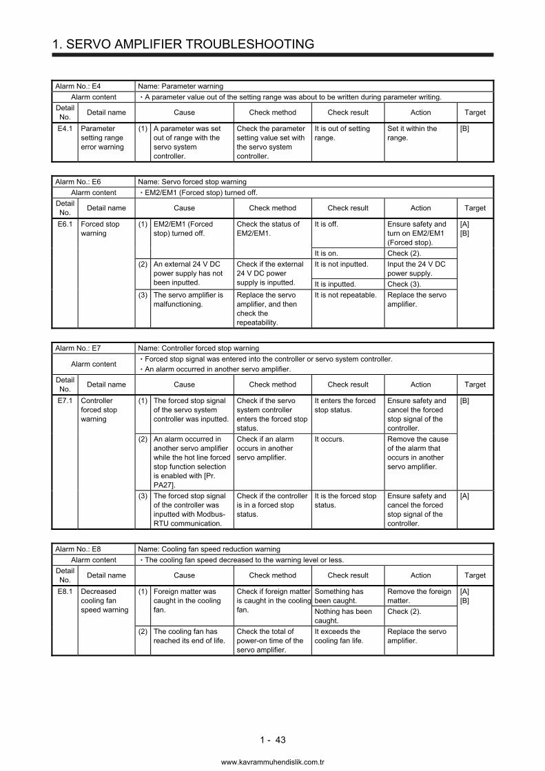
1. SERVO AMPLIFIER TROUBLESHOOTING
1 - 43
Alarm No.: E4 Name: Parameter warning
Alarm content A parameter value out of the setting range was about to be written during parameter writing.
Detail No.
Detail name Cause Check method Check result Action Target
E4.1 Parameter setting range error warning
(1) A parameter was set out of range with the servo system controller.
Check the parameter setting value set with the servo system controller.
It is out of setting range.
Set it within the range.
[B]
Alarm No.: E6 Name: Servo forced stop warning
Alarm content EM2/EM1 (Forced stop) turned off.
Detail No.
Detail name Cause Check method Check result Action Target
E6.1 Forced stop warning
(1) EM2/EM1 (Forced stop) turned off.
Check the status of EM2/EM1.
It is off. Ensure safety and turn on EM2/EM1 (Forced stop).
[A] [B]
It is on. Check (2).
(2) An external 24 V DC power supply has not been inputted.
Check if the external 24 V DC power supply is inputted.
It is not inputted. Input the 24 V DC power supply.
It is inputted. Check (3).
(3) The servo amplifier is malfunctioning.
Replace the servo amplifier, and then check the repeatability.
It is not repeatable. Replace the servo amplifier.
Alarm No.: E7 Name: Controller forced stop warning
Alarm content Forced stop signal was entered into the controller or servo system controller. An alarm occurred in another servo amplifier.
Detail No.
Detail name Cause Check method Check result Action Target
E7.1 Controller forced stop warning
(1) The forced stop signal of the servo system controller was inputted.
Check if the servo system controller enters the forced stop status.
It enters the forced stop status.
Ensure safety and cancel the forced stop signal of the controller.
[B]
(2) An alarm occurred in another servo amplifier while the hot line forced stop function selection is enabled with [Pr. PA27].
Check if an alarm occurs in another servo amplifier.
It occurs. Remove the cause of the alarm that occurs in another servo amplifier.
(3) The forced stop signal of the controller was inputted with Modbus-RTU communication.
Check if the controller is in a forced stop status.
It is the forced stop status.
Ensure safety and cancel the forced stop signal of the controller.
[A]
Alarm No.: E8 Name: Cooling fan speed reduction warning
Alarm content The cooling fan speed decreased to the warning level or less.
Detail No.
Detail name Cause Check method Check result Action Target
E8.1 Decreased cooling fan speed warning
(1) Foreign matter was caught in the cooling fan.
Check if foreign matter is caught in the cooling fan.
Something has been caught.
Remove the foreign matter.
[A] [B]
Nothing has been caught.
Check (2).
(2) The cooling fan has reached its end of life.
Check the total of power-on time of the servo amplifier.
It exceeds the cooling fan life.
Replace the servo amplifier.
www.kavrammuhendislik.com.tr
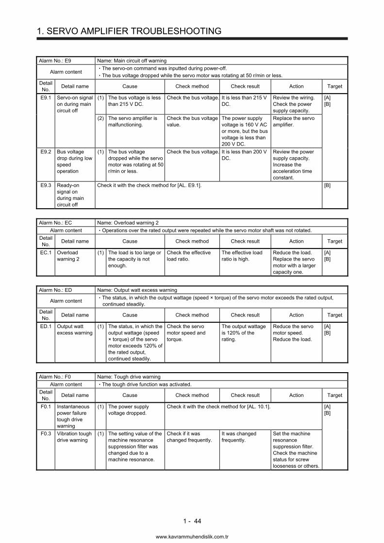
1. SERVO AMPLIFIER TROUBLESHOOTING
1 - 44
Alarm No.: E9 Name: Main circuit off warning
Alarm content The servo-on command was inputted during power-off. The bus voltage dropped while the servo motor was rotating at 50 r/min or less.
Detail No.
Detail name Cause Check method Check result Action Target
E9.1 Servo-on signal on during main circuit off
(1) The bus voltage is less than 215 V DC.
Check the bus voltage. It is less than 215 V DC.
Review the wiring. Check the power supply capacity.
[A] [B]
(2) The servo amplifier is malfunctioning.
Check the bus voltage value.
The power supply voltage is 160 V AC or more, but the bus voltage is less than 200 V DC.
Replace the servo amplifier.
E9.2 Bus voltage drop during low speed operation
(1) The bus voltage dropped while the servo motor was rotating at 50 r/min or less.
Check the bus voltage. It is less than 200 V DC.
Review the power supply capacity. Increase the acceleration time constant.
E9.3 Ready-on signal on during main circuit off
Check it with the check method for [AL. E9.1]. [B]
Alarm No.: EC Name: Overload warning 2
Alarm content Operations over the rated output were repeated while the servo motor shaft was not rotated.
Detail No.
Detail name Cause Check method Check result Action Target
EC.1 Overload warning 2
(1) The load is too large or the capacity is not enough.
Check the effective load ratio.
The effective load ratio is high.
Reduce the load. Replace the servo motor with a larger capacity one.
[A] [B]
Alarm No.: ED Name: Output watt excess warning
Alarm content The status, in which the output wattage (speed × torque) of the servo motor exceeds the rated output, continued steadily.
Detail No.
Detail name Cause Check method Check result Action Target
ED.1 Output watt excess warning
(1) The status, in which the output wattage (speed × torque) of the servo motor exceeds 120% of the rated output, continued steadily.
Check the servo motor speed and torque.
The output wattage is 120% of the rating.
Reduce the servo motor speed. Reduce the load.
[A] [B]
Alarm No.: F0 Name: Tough drive warning
Alarm content The tough drive function was activated.
Detail No.
Detail name Cause Check method Check result Action Target
F0.1 Instantaneous power failure tough drive warning
(1) The power supply voltage dropped.
Check it with the check method for [AL. 10.1]. [A] [B]
F0.3 Vibration tough drive warning
(1) The setting value of the machine resonance suppression filter was changed due to a machine resonance.
Check if it was changed frequently.
It was changed frequently.
Set the machine resonance suppression filter. Check the machine status for screw looseness or others.
www.kavrammuhendislik.com.tr
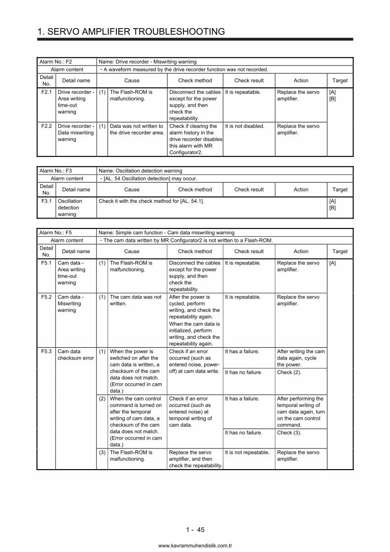
1. SERVO AMPLIFIER TROUBLESHOOTING
1 - 45
Alarm No.: F2 Name: Drive recorder - Miswriting warning
Alarm content A waveform measured by the drive recorder function was not recorded.
Detail No.
Detail name Cause Check method Check result Action Target
F2.1 Drive recorder - Area writing time-out warning
(1) The Flash-ROM is malfunctioning.
Disconnect the cables except for the power supply, and then check the repeatability.
It is repeatable. Replace the servo amplifier.
[A] [B]
F2.2 Drive recorder - Data miswriting warning
(1) Data was not written to the drive recorder area.
Check if clearing the alarm history in the drive recorder disables this alarm with MR Configurator2.
It is not disabled. Replace the servo amplifier.
Alarm No.: F3 Name: Oscillation detection warning
Alarm content [AL. 54 Oscillation detection] may occur.
Detail No.
Detail name Cause Check method Check result Action Target
F3.1 Oscillation detection warning
Check it with the check method for [AL. 54.1]. [A] [B]
Alarm No.: F5 Name: Simple cam function - Cam data miswriting warning
Alarm content The cam data written by MR Configurator2 is not written to a Flash-ROM.
Detail No.
Detail name Cause Check method Check result Action Target
F5.1 Cam data - Area writing time-out warning
(1) The Flash-ROM is malfunctioning.
Disconnect the cables except for the power supply, and then check the repeatability.
It is repeatable. Replace the servo amplifier.
[A]
F5.2 Cam data - Miswriting warning
(1) The cam data was not written.
After the power is cycled, perform writing, and check the repeatability again. When the cam data is initialized, perform writing, and check the repeatability again.
It is repeatable. Replace the servo amplifier.
F5.3 Cam data checksum error
(1) When the power is switched on after the cam data is written, a checksum of the cam data does not match. (Error occurred in cam data.)
Check if an error occurred (such as entered noise, power-off) at cam data write.
It has a failure. After writing the cam data again, cycle the power.
It has no failure. Check (2).
(2) When the cam control command is turned on after the temporal writing of cam data, a checksum of the cam data does not match. (Error occurred in cam data.)
Check if an error occurred (such as entered noise) at temporal writing of cam data.
It has a failure. After performing the temporal writing of cam data again, turn on the cam control command.
It has no failure. Check (3).
(3) The Flash-ROM is malfunctioning.
Replace the servo amplifier, and then check the repeatability.
It is not repeatable. Replace the servo amplifier.
www.kavrammuhendislik.com.tr
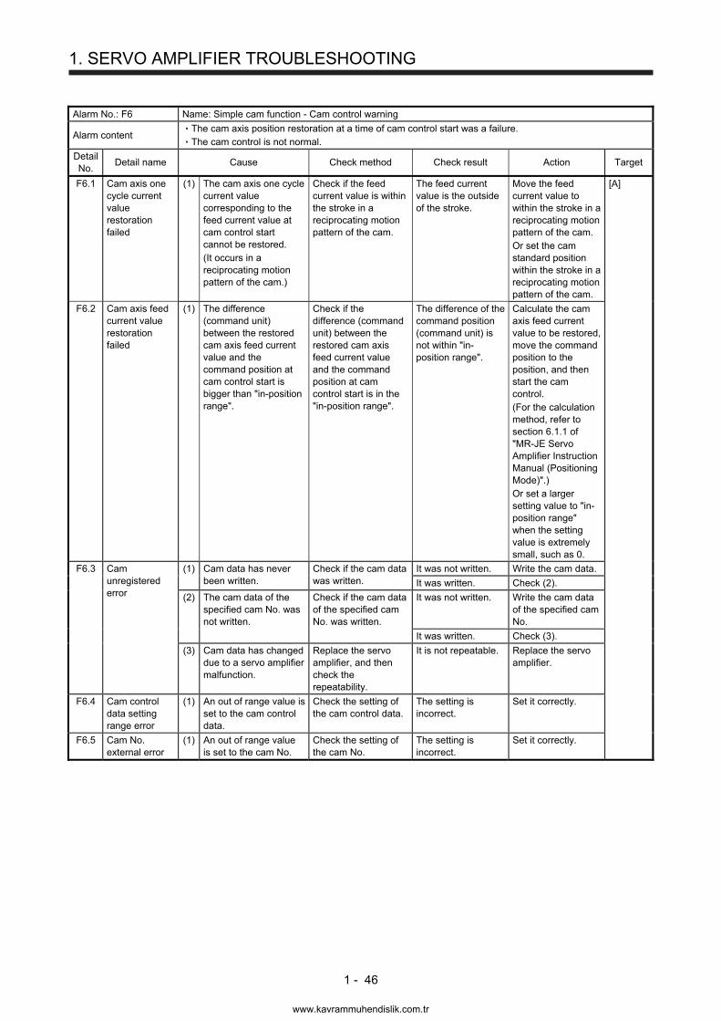
1. SERVO AMPLIFIER TROUBLESHOOTING
1 - 46
Alarm No.: F6 Name: Simple cam function - Cam control warning
Alarm content The cam axis position restoration at a time of cam control start was a failure. The cam control is not normal.
Detail No.
Detail name Cause Check method Check result Action Target
F6.1 Cam axis one cycle current value restoration failed
(1) The cam axis one cycle current value corresponding to the feed current value at cam control start cannot be restored. (It occurs in a reciprocating motion pattern of the cam.)
Check if the feed current value is within the stroke in a reciprocating motion pattern of the cam.
The feed current value is the outside of the stroke.
Move the feed current value to within the stroke in a reciprocating motion pattern of the cam. Or set the cam standard position within the stroke in a reciprocating motion pattern of the cam.
[A]
F6.2 Cam axis feed current value restoration failed
(1) The difference (command unit) between the restored cam axis feed current value and the command position at cam control start is bigger than "in-position range".
Check if the difference (command unit) between the restored cam axis feed current value and the command position at cam control start is in the "in-position range".
The difference of the command position (command unit) is not within "in-position range".
Calculate the cam axis feed current value to be restored, move the command position to the position, and then start the cam control. (For the calculation method, refer to section 6.1.1 of "MR-JE Servo Amplifier Instruction Manual (Positioning Mode)".) Or set a larger setting value to "in-position range" when the setting value is extremely small, such as 0.
F6.3 Cam unregistered error
(1) Cam data has never been written.
Check if the cam data was written.
It was not written. Write the cam data.
It was written. Check (2).
(2) The cam data of the specified cam No. was not written.
Check if the cam data of the specified cam No. was written.
It was not written. Write the cam data of the specified cam No.
It was written. Check (3).
(3) Cam data has changed due to a servo amplifier malfunction.
Replace the servo amplifier, and then check the repeatability.
It is not repeatable. Replace the servo amplifier.
F6.4 Cam control data setting range error
(1) An out of range value is set to the cam control data.
Check the setting of the cam control data.
The setting is incorrect.
Set it correctly.
F6.5 Cam No. external error
(1) An out of range value is set to the cam No.
Check the setting of the cam No.
The setting is incorrect.
Set it correctly.
www.kavrammuhendislik.com.tr
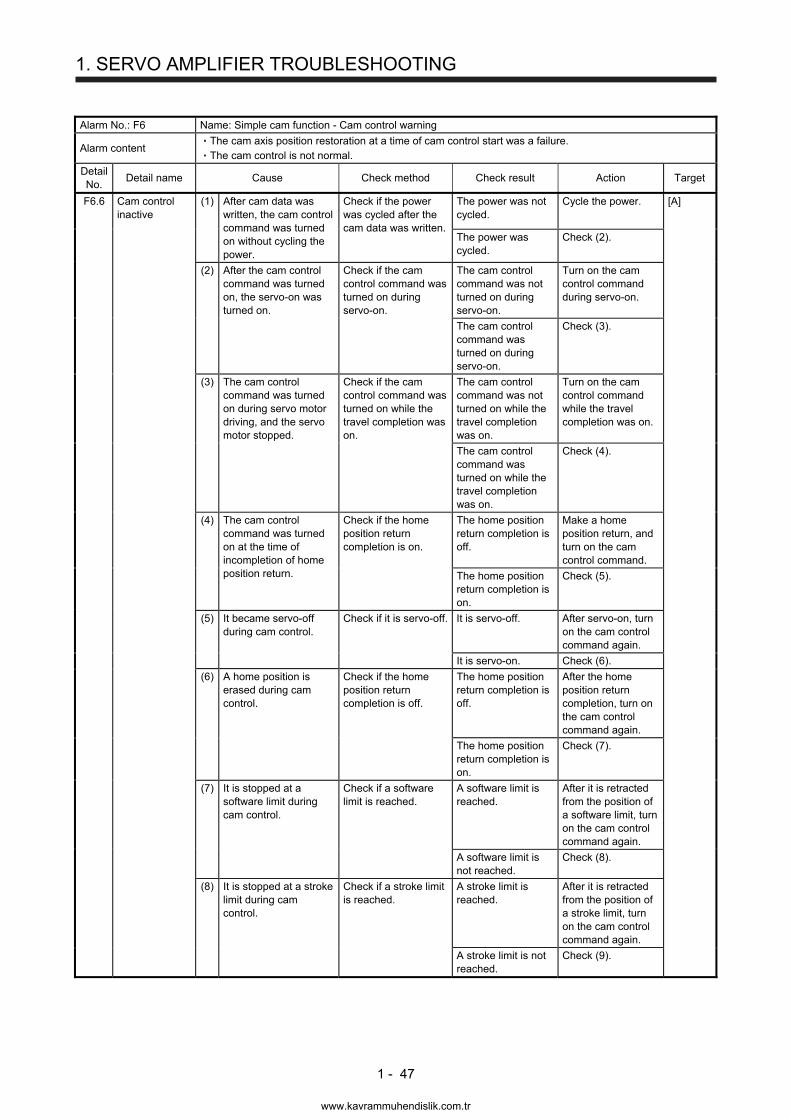
1. SERVO AMPLIFIER TROUBLESHOOTING
1 - 47
Alarm No.: F6 Name: Simple cam function - Cam control warning
Alarm content The cam axis position restoration at a time of cam control start was a failure. The cam control is not normal.
Detail No.
Detail name Cause Check method Check result Action Target
F6.6 Cam control inactive
(1) After cam data was written, the cam control command was turned on without cycling the power.
Check if the power was cycled after the cam data was written.
The power was not cycled.
Cycle the power. [A]
The power was cycled.
Check (2).
(2) After the cam control command was turned on, the servo-on was turned on.
Check if the cam control command was turned on during servo-on.
The cam control command was not turned on during servo-on.
Turn on the cam control command during servo-on.
The cam control command was turned on during servo-on.
Check (3).
(3) The cam control command was turned on during servo motor driving, and the servo motor stopped.
Check if the cam control command was turned on while the travel completion was on.
The cam control command was not turned on while the travel completion was on.
Turn on the cam control command while the travel completion was on.
The cam control command was turned on while the travel completion was on.
Check (4).
(4) The cam control command was turned on at the time of incompletion of home position return.
Check if the home position return completion is on.
The home position return completion is off.
Make a home position return, and turn on the cam control command.
The home position return completion is on.
Check (5).
(5) It became servo-off during cam control.
Check if it is servo-off. It is servo-off. After servo-on, turn on the cam control command again.
It is servo-on. Check (6).
(6) A home position is erased during cam control.
Check if the home position return completion is off.
The home position return completion is off.
After the home position return completion, turn on the cam control command again.
The home position return completion is on.
Check (7).
(7) It is stopped at a software limit during cam control.
Check if a software limit is reached.
A software limit is reached.
After it is retracted from the position of a software limit, turn on the cam control command again.
A software limit is not reached.
Check (8).
(8) It is stopped at a stroke limit during cam control.
Check if a stroke limit is reached.
A stroke limit is reached.
After it is retracted from the position of a stroke limit, turn on the cam control command again.
A stroke limit is not reached.
Check (9).
www.kavrammuhendislik.com.tr
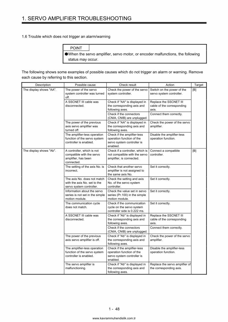
1. SERVO AMPLIFIER TROUBLESHOOTING
1 - 48
1.6 Trouble which does not trigger an alarm/warning
POINT
When the servo amplifier, servo motor, or encoder malfunctions, the following status may occur.
The following shows some examples of possible causes which do not trigger an alarm or warning. Remove each cause by referring to this section.
Description Possible cause Check result Action Target
The display shows "AA". The power of the servo system controller was turned off.
Check the power of the servo system controller.
Switch on the power of the servo system controller.
[B]
A SSCNET III cable was disconnected.
Check if "AA" is displayed in the corresponding axis and following axes.
Replace the SSCNET III cable of the corresponding axis.
Check if the connectors (CNIA, CNIB) are unplugged.
Connect them correctly.
The power of the previous axis servo amplifier was turned off.
Check if "AA" is displayed in the corresponding axis and following axes.
Check the power of the servo amplifier.
The amplifier-less operation function of the servo system controller is enabled.
Check if the amplifier-less operation function of the servo system controller is enabled.
Disable the amplifier-less operation function.
The display shows "Ab". A controller, which is not compatible with the servo amplifier, has been connected.
Check if a controller, which is not compatible with the servo amplifier, is connected.
Connect a compatible controller.
[B]
The setting of the axis No. is incorrect.
Check that another servo amplifier is not assigned to the same axis No.
Set it correctly.
The axis No. does not match with the axis No. set to the servo system controller.
Check the setting and axis No. of the servo system controller.
Set it correctly.
Information about the servo series is not set in the simple motion module.
Check the value set in servo series (Pr.100) in the simple motion module.
Set it correctly.
The communication cycle does not match.
Check if the communication cycle on the servo system controller side is 0.222 ms.
Set it correctly.
A SSCNET III cable was disconnected.
Check if "Ab" is displayed in the corresponding axis and following axes.
Replace the SSCNET III cable of the corresponding axis.
Check if the connectors (CNIA, CNIB) are unplugged.
Connect them correctly.
The power of the previous axis servo amplifier is off.
Check if "Ab" is displayed in the corresponding axis and following axes.
Check the power of the servo amplifier.
The amplifier-less operation function of the servo system controller is enabled.
Check if the amplifier-less operation function of the servo system controller is enabled.
Disable the amplifier-less operation function.
The servo amplifier is malfunctioning.
Check if "Ab" is displayed in the corresponding axis and following axes.
Replace the servo amplifier of the corresponding axis.
www.kavrammuhendislik.com.tr
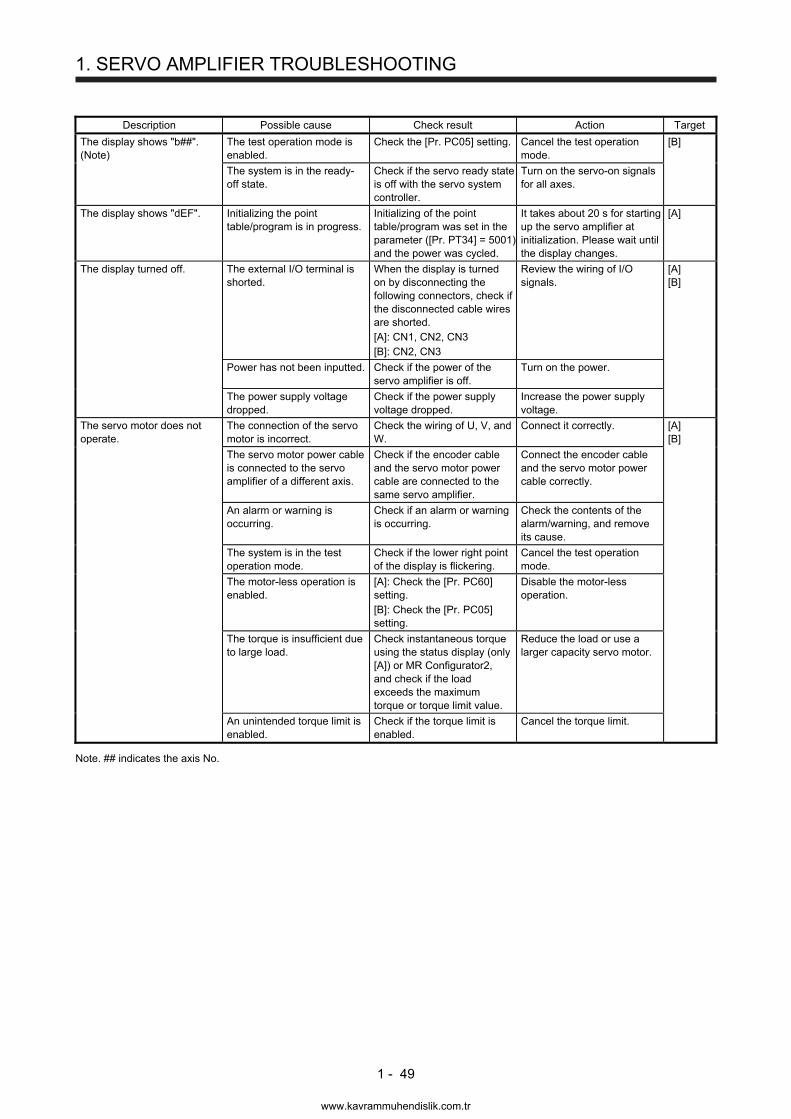
1. SERVO AMPLIFIER TROUBLESHOOTING
1 - 49
Description Possible cause Check result Action Target
The display shows "b##". (Note)
The test operation mode is enabled.
Check the [Pr. PC05] setting. Cancel the test operation mode.
[B]
The system is in the ready-off state.
Check if the servo ready state is off with the servo system controller.
Turn on the servo-on signals for all axes.
The display shows "dEF". Initializing the point table/program is in progress.
Initializing of the point table/program was set in the parameter ([Pr. PT34] = 5001) and the power was cycled.
It takes about 20 s for starting up the servo amplifier at initialization. Please wait until the display changes.
[A]
The display turned off. The external I/O terminal is shorted.
When the display is turned on by disconnecting the following connectors, check if the disconnected cable wires are shorted. [A]: CN1, CN2, CN3 [B]: CN2, CN3
Review the wiring of I/O signals.
[A] [B]
Power has not been inputted. Check if the power of the servo amplifier is off.
Turn on the power.
The power supply voltage dropped.
Check if the power supply voltage dropped.
Increase the power supply voltage.
The servo motor does not operate.
The connection of the servo motor is incorrect.
Check the wiring of U, V, and W.
Connect it correctly. [A] [B]
The servo motor power cable is connected to the servo amplifier of a different axis.
Check if the encoder cable and the servo motor power cable are connected to the same servo amplifier.
Connect the encoder cable and the servo motor power cable correctly.
An alarm or warning is occurring.
Check if an alarm or warning is occurring.
Check the contents of the alarm/warning, and remove its cause.
The system is in the test operation mode.
Check if the lower right point of the display is flickering.
Cancel the test operation mode.
The motor-less operation is enabled.
[A]: Check the [Pr. PC60] setting. [B]: Check the [Pr. PC05] setting.
Disable the motor-less operation.
The torque is insufficient due to large load.
Check instantaneous torque using the status display (only [A]) or MR Configurator2, and check if the load exceeds the maximum torque or torque limit value.
Reduce the load or use a larger capacity servo motor.
An unintended torque limit is enabled.
Check if the torque limit is enabled.
Cancel the torque limit.
Note. ## indicates the axis No.
www.kavrammuhendislik.com.tr

1. SERVO AMPLIFIER TROUBLESHOOTING
1 - 50
Description Possible cause Check result Action Target
The servo motor does not operate.
The setting of the torque limit is incorrect.
Check if the torque limit value is "0". [A]: [Pr. PA11] and [Pr. PA12], or analog input [B]: Setting on the controller side
Set it correctly. [A] [B]
A machine is interfering with the servo motor.
Check if a machine is interfering.
Remove the interference.
For a servo motor with an electromagnetic brake, the brake has not been released.
Check the power supply of the electromagnetic brake.
Turn on the electromagnetic brake power.
LSP (Forward rotation stroke end) and LSN (Reverse rotation stroke end) are not on.
Check if [AL. 99] is occurring. Turn on LSP and LSN. [A]
SON (Servo-on) is not on. Check the SON (Servo-on) state.
Turn on SON (Servo-on).
RES (Reset) is on. Check the RES (Reset) state.
Turn off RES (Reset).
The setting of the control mode is incorrect.
Check the [Pr. PA01] setting. Set it correctly.
The command pulse is not inputted in the position control mode.
Check if the pulse train is outputted on the controller side.
Review the setting on the controller side.
The wiring of the command pulse train signal is incorrect in the position control mode.
Check the cumulative command pulses using the status display or MR Configurator2. Input the pulse train command and check if the display changes.
Review the wiring. When the signal is used in open collector type, input 24 V DC to OPC.
The setting of the command pulse input form is incorrect in the position control mode.
Check if the pulse train form outputted with the controller and the setting of [Pr. PA13] are matched.
Review the [Pr. PA13] setting.
Both of ST1 (Forward rotation start) and ST2 (Reverse rotation start) are on or off in the speed control mode or the positioning mode.
Check the status of ST1 (Forward rotation start) and ST2 (Reverse rotation start).
Turn on ST1 (Forward rotation start) or ST2 (Reverse rotation start).
Both of RS1 (Forward rotation selection) and RS2 (Reverse rotation selection) are on or off in the torque control mode.
Check the status of RS1 (Forward rotation selection) and RS2 (Reverse rotation selection).
Turn on RS1 (Forward rotation selection) or RS2 (Reverse rotation selection).
The value selected in the speed control mode or the torque control mode is low.
Check SP1 (Speed selection 1), SP2 (Speed selection 2), and SP3 (Speed selection 3), and then check if the selected internal speed is correct.
Review the selections of SP1 (Speed selection 1), SP2 (Speed selection 2), SP3 (Speed selection 3), and setting of internal speed.
An analog signal is not inputted correctly.
Check the values of the analog speed command and the analog torque command using the status display or MR Configurator2.
Input the analog signal correctly.
The setting of point tables is incorrect.
Check the point table setting. Review the point table setting.
www.kavrammuhendislik.com.tr
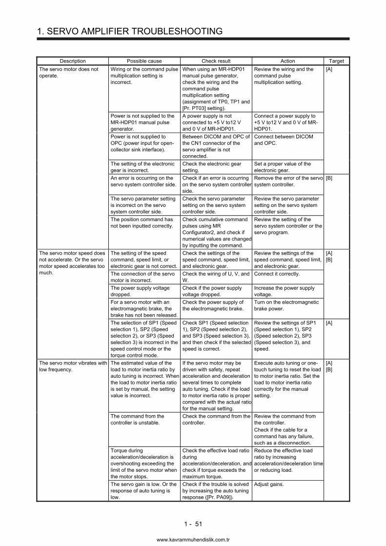
1. SERVO AMPLIFIER TROUBLESHOOTING
1 - 51
Description Possible cause Check result Action Target
The servo motor does not operate.
Wiring or the command pulse multiplication setting is incorrect.
When using an MR-HDP01 manual pulse generator, check the wiring and the command pulse multiplication setting (assignment of TP0, TP1 and [Pr. PT03] setting).
Review the wiring and the command pulse multiplication setting.
[A]
Power is not supplied to the MR-HDP01 manual pulse generator.
A power supply is not connected to +5 V to12 V and 0 V of MR-HDP01.
Connect a power supply to +5 V to12 V and 0 V of MR-HDP01.
Power is not supplied to OPC (power input for open-collector sink interface).
Between DICOM and OPC of the CN1 connector of the servo amplifier is not connected.
Connect between DICOM and OPC.
The setting of the electronic gear is incorrect.
Check the electronic gear setting.
Set a proper value of the electronic gear.
An error is occurring on the servo system controller side.
Check if an error is occurring on the servo system controller side.
Remove the error of the servo system controller.
[B]
The servo parameter setting is incorrect on the servo system controller side.
Check the servo parameter setting on the servo system controller side.
Review the servo parameter setting on the servo system controller side.
The position command has not been inputted correctly.
Check cumulative command pulses using MR Configurator2, and check if numerical values are changed by inputting the command.
Review the setting of the servo system controller or the servo program.
The servo motor speed does not accelerate. Or the servo motor speed accelerates too much.
The setting of the speed command, speed limit, or electronic gear is not correct.
Check the settings of the speed command, speed limit, and electronic gear.
Review the settings of the speed command, speed limit, and electronic gear.
[A] [B]
The connection of the servo motor is incorrect.
Check the wiring of U, V, and W.
Connect it correctly.
The power supply voltage dropped.
Check if the power supply voltage dropped.
Increase the power supply voltage.
For a servo motor with an electromagnetic brake, the brake has not been released.
Check the power supply of the electromagnetic brake.
Turn on the electromagnetic brake power.
The selection of SP1 (Speed selection 1), SP2 (Speed selection 2), or SP3 (Speed selection 3) is incorrect in the speed control mode or the torque control mode.
Check SP1 (Speed selection 1), SP2 (Speed selection 2), and SP3 (Speed selection 3), and then check if the selected speed is correct.
Review the settings of SP1 (Speed selection 1), SP2 (Speed selection 2), SP3 (Speed selection 3), and speed.
[A]
The servo motor vibrates with low frequency.
The estimated value of the load to motor inertia ratio by auto tuning is incorrect. When the load to motor inertia ratio is set by manual, the setting value is incorrect.
If the servo motor may be driven with safety, repeat acceleration and deceleration several times to complete auto tuning. Check if the load to motor inertia ratio is proper compared with the actual ratio for the manual setting.
Execute auto tuning or one-touch tuning to reset the load to motor inertia ratio. Set the load to motor inertia ratio correctly for the manual setting.
[A] [B]
The command from the controller is unstable.
Check the command from the controller.
Review the command from the controller. Check if the cable for a command has any failure, such as a disconnection.
Torque during acceleration/deceleration is overshooting exceeding the limit of the servo motor when the motor stops.
Check the effective load ratio during acceleration/deceleration, and check if torque exceeds the maximum torque.
Reduce the effective load ratio by increasing acceleration/deceleration time or reducing load.
The servo gain is low. Or the response of auto tuning is low.
Check if the trouble is solved by increasing the auto tuning response ([Pr. PA09]).
Adjust gains.
www.kavrammuhendislik.com.tr

1. SERVO AMPLIFIER TROUBLESHOOTING
1 - 52
Description Possible cause Check result Action Target
An unusual noise is occurring at the servo motor.
The servo gain is low. Or the response of auto tuning is low.
Check if the trouble is solved by increasing the auto tuning response ([Pr. PA09]).
Adjust gains. [A] [B]
A bearing is at the end of its life.
If the servo motor can be driven safely, remove the load and check only the servo motor for a noise. If the servo motor can be removed from the machine, remove the servo motor power cable to release the brake, and check a noise by rotating the servo motor with the hands.
When a noise occurs, the bearing is at the end of its life. Replace the servo motor. When no noise occurs, maintain the machine.
For a servo motor with an electromagnetic brake, the brake has not been released.
Check the power supply of the electromagnetic brake.
Turn on the electromagnetic brake power.
For a servo motor with an electromagnetic brake, the brake release timing is not correct.
Check the brake release timing.
Review the brake release timing. Please consider that the electromagnetic brake has release delay time.
The servo motor vibrates. The servo gain is too high. Or the response of auto tuning is too high.
Check if the trouble is solved by reducing the auto tuning response ([Pr. PA09]).
Adjust gains. [A] [B]
The machine is vibrating (resonating).
If the servo motor can be driven safely, check if the trouble is solved by one-touch tuning or adaptive tuning.
Adjust the machine resonance suppression filter.
The load side is vibrating. If the servo motor can be driven safely, check if the trouble is solved by advanced vibration suppression control II.
Execute the advanced vibration suppression control II.
Feedback pulses are being miscounted due to entered noise into an encoder cable.
Check cumulative feedback pulses using the status display (only [A]) or MR Configurator2, and check if its numerical value is skipped.
Please take countermeasures against noise by laying the encoder cable apart from power cables, etc.
There is a backlash between the servo motor and machine (such as a gear and coupling).
Check if there is a backlash on the machine part.
Adjust the backlash on the coupling and machine part.
The rigidity of the servo motor mounting part is low.
Check the mounting part of the servo motor.
Increase the rigidity of the mounting part by methods, such as increasing the board thickness and reinforcing the part with ribs.
The connection of the servo motor is incorrect.
Check the wiring of U, V, and W.
Connect it correctly.
An unbalanced torque of the machine is large.
Check if the vibration varies depending on the speed.
Adjust the balance of the machine.
The eccentricity due to a core gap is large.
Check the mounting accuracy of the servo motor and machine.
Review the accuracy.
A load for the shaft of the servo motor is large.
Check the load for the shaft of the servo motor.
Adjust the load for the shaft to within the specifications of the servo motor. For the shaft permissible load, refer to "HG-KN_-S100/HG-SN_-S100 Servo Motor Instruction Manual".
An external vibration propagated to the servo motor.
Check the vibration from outside.
Prevent the vibration from the external vibration source.
www.kavrammuhendislik.com.tr
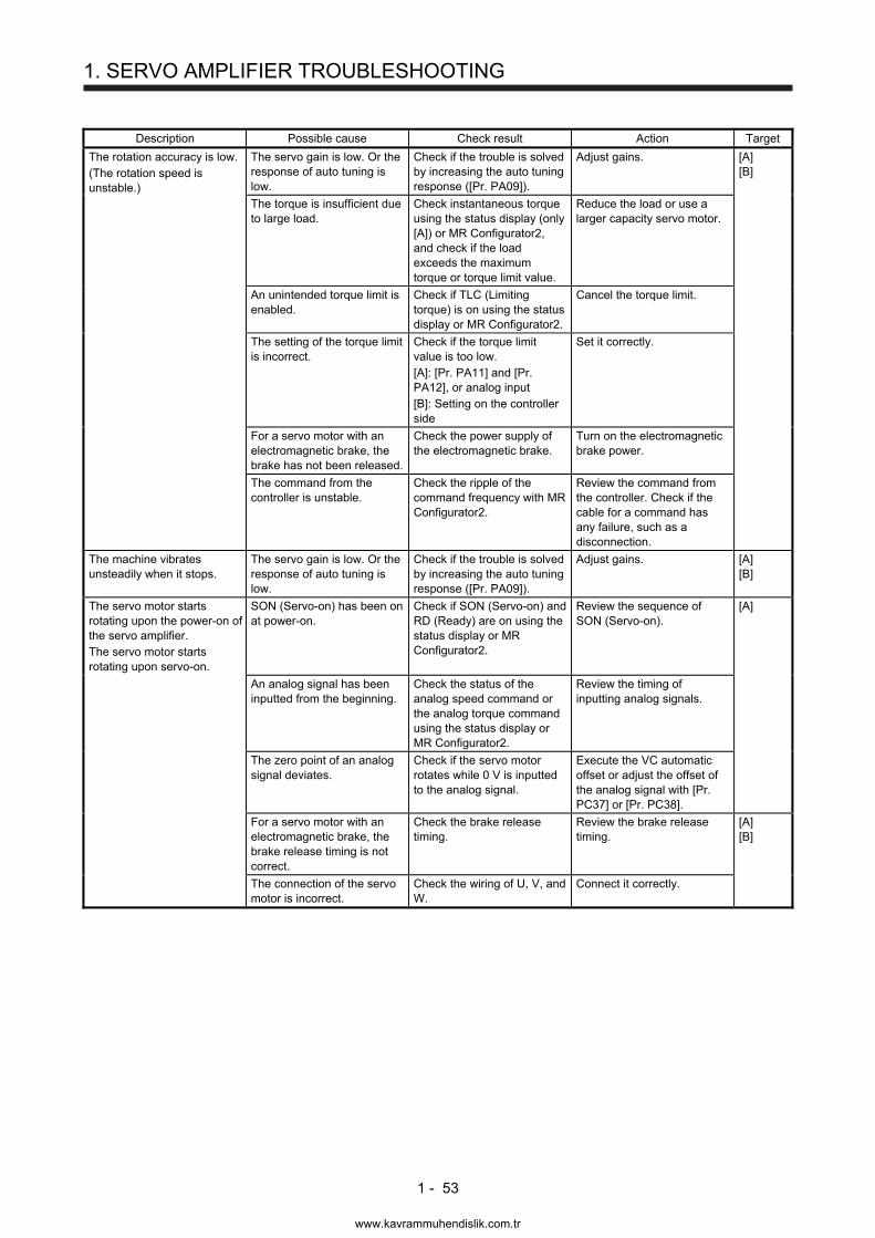
1. SERVO AMPLIFIER TROUBLESHOOTING
1 - 53
Description Possible cause Check result Action Target
The rotation accuracy is low. (The rotation speed is unstable.)
The servo gain is low. Or the response of auto tuning is low.
Check if the trouble is solved by increasing the auto tuning response ([Pr. PA09]).
Adjust gains. [A] [B]
The torque is insufficient due to large load.
Check instantaneous torque using the status display (only [A]) or MR Configurator2, and check if the load exceeds the maximum torque or torque limit value.
Reduce the load or use a larger capacity servo motor.
An unintended torque limit is enabled.
Check if TLC (Limiting torque) is on using the status display or MR Configurator2.
Cancel the torque limit.
The setting of the torque limit is incorrect.
Check if the torque limit value is too low. [A]: [Pr. PA11] and [Pr. PA12], or analog input [B]: Setting on the controller side
Set it correctly.
For a servo motor with an electromagnetic brake, the brake has not been released.
Check the power supply of the electromagnetic brake.
Turn on the electromagnetic brake power.
The command from the controller is unstable.
Check the ripple of the command frequency with MR Configurator2.
Review the command from the controller. Check if the cable for a command has any failure, such as a disconnection.
The machine vibrates unsteadily when it stops.
The servo gain is low. Or the response of auto tuning is low.
Check if the trouble is solved by increasing the auto tuning response ([Pr. PA09]).
Adjust gains. [A] [B]
The servo motor starts rotating upon the power-on of the servo amplifier. The servo motor starts rotating upon servo-on.
SON (Servo-on) has been on at power-on.
Check if SON (Servo-on) and RD (Ready) are on using the status display or MR Configurator2.
Review the sequence of SON (Servo-on).
[A]
An analog signal has been inputted from the beginning.
Check the status of the analog speed command or the analog torque command using the status display or MR Configurator2.
Review the timing of inputting analog signals.
The zero point of an analog signal deviates.
Check if the servo motor rotates while 0 V is inputted to the analog signal.
Execute the VC automatic offset or adjust the offset of the analog signal with [Pr. PC37] or [Pr. PC38].
For a servo motor with an electromagnetic brake, the brake release timing is not correct.
Check the brake release timing.
Review the brake release timing.
[A] [B]
The connection of the servo motor is incorrect.
Check the wiring of U, V, and W.
Connect it correctly.
www.kavrammuhendislik.com.tr
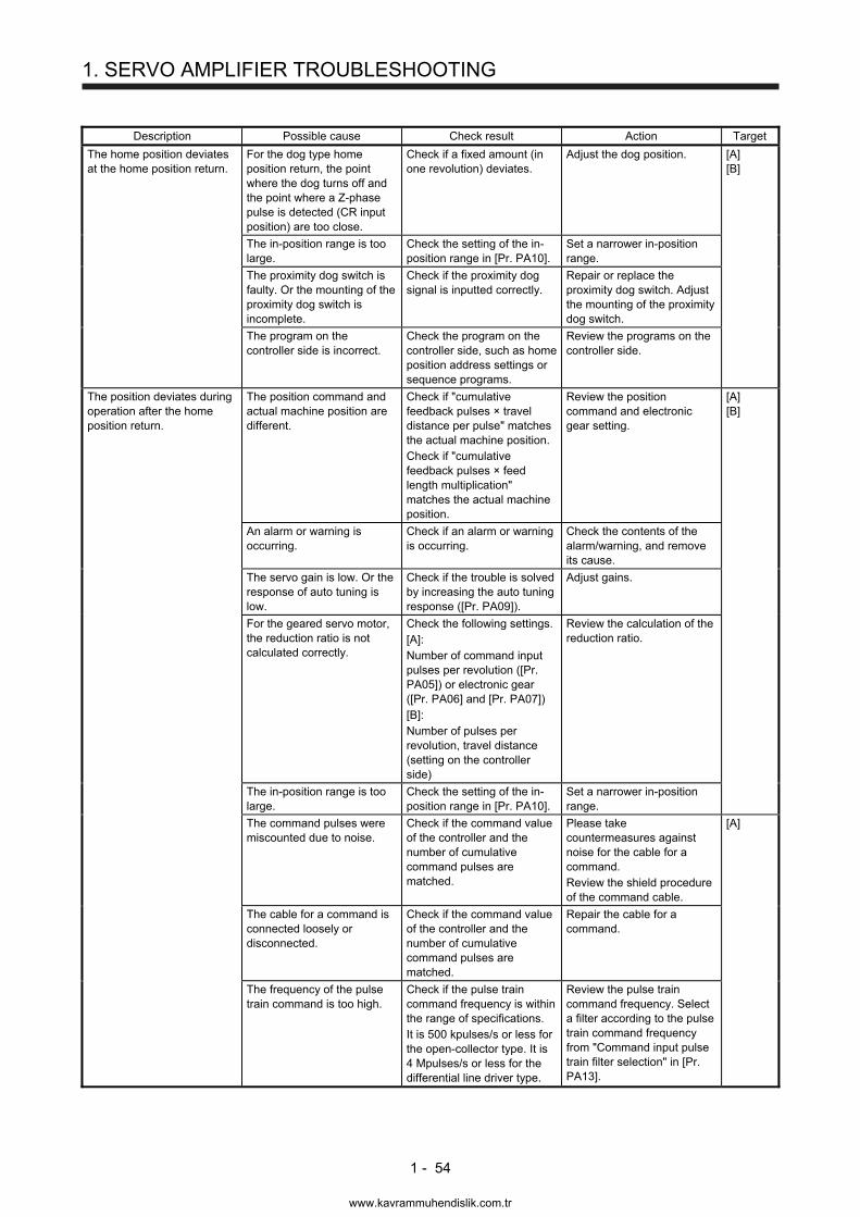
1. SERVO AMPLIFIER TROUBLESHOOTING
1 - 54
Description Possible cause Check result Action Target
The home position deviates at the home position return.
For the dog type home position return, the point where the dog turns off and the point where a Z-phase pulse is detected (CR input position) are too close.
Check if a fixed amount (in one revolution) deviates.
Adjust the dog position. [A] [B]
The in-position range is too large.
Check the setting of the in-position range in [Pr. PA10].
Set a narrower in-position range.
The proximity dog switch is faulty. Or the mounting of the proximity dog switch is incomplete.
Check if the proximity dog signal is inputted correctly.
Repair or replace the proximity dog switch. Adjust the mounting of the proximity dog switch.
The program on the controller side is incorrect.
Check the program on the controller side, such as home position address settings or sequence programs.
Review the programs on the controller side.
The position deviates during operation after the home position return.
The position command and actual machine position are different.
Check if "cumulative feedback pulses × travel distance per pulse" matches the actual machine position. Check if "cumulative feedback pulses × feed length multiplication" matches the actual machine position.
Review the position command and electronic gear setting.
[A] [B]
An alarm or warning is occurring.
Check if an alarm or warning is occurring.
Check the contents of the alarm/warning, and remove its cause.
The servo gain is low. Or the response of auto tuning is low.
Check if the trouble is solved by increasing the auto tuning response ([Pr. PA09]).
Adjust gains.
For the geared servo motor, the reduction ratio is not calculated correctly.
Check the following settings. [A]: Number of command input pulses per revolution ([Pr. PA05]) or electronic gear ([Pr. PA06] and [Pr. PA07]) [B]: Number of pulses per revolution, travel distance (setting on the controller side)
Review the calculation of the reduction ratio.
The in-position range is too large.
Check the setting of the in-position range in [Pr. PA10].
Set a narrower in-position range.
The command pulses were miscounted due to noise.
Check if the command value of the controller and the number of cumulative command pulses are matched.
Please take countermeasures against noise for the cable for a command. Review the shield procedure of the command cable.
[A]
The cable for a command is connected loosely or disconnected.
Check if the command value of the controller and the number of cumulative command pulses are matched.
Repair the cable for a command.
The frequency of the pulse train command is too high.
Check if the pulse train command frequency is within the range of specifications. It is 500 kpulses/s or less for the open-collector type. It is 4 Mpulses/s or less for the differential line driver type.
Review the pulse train command frequency. Select a filter according to the pulse train command frequency from "Command input pulse train filter selection" in [Pr. PA13].
www.kavrammuhendislik.com.tr
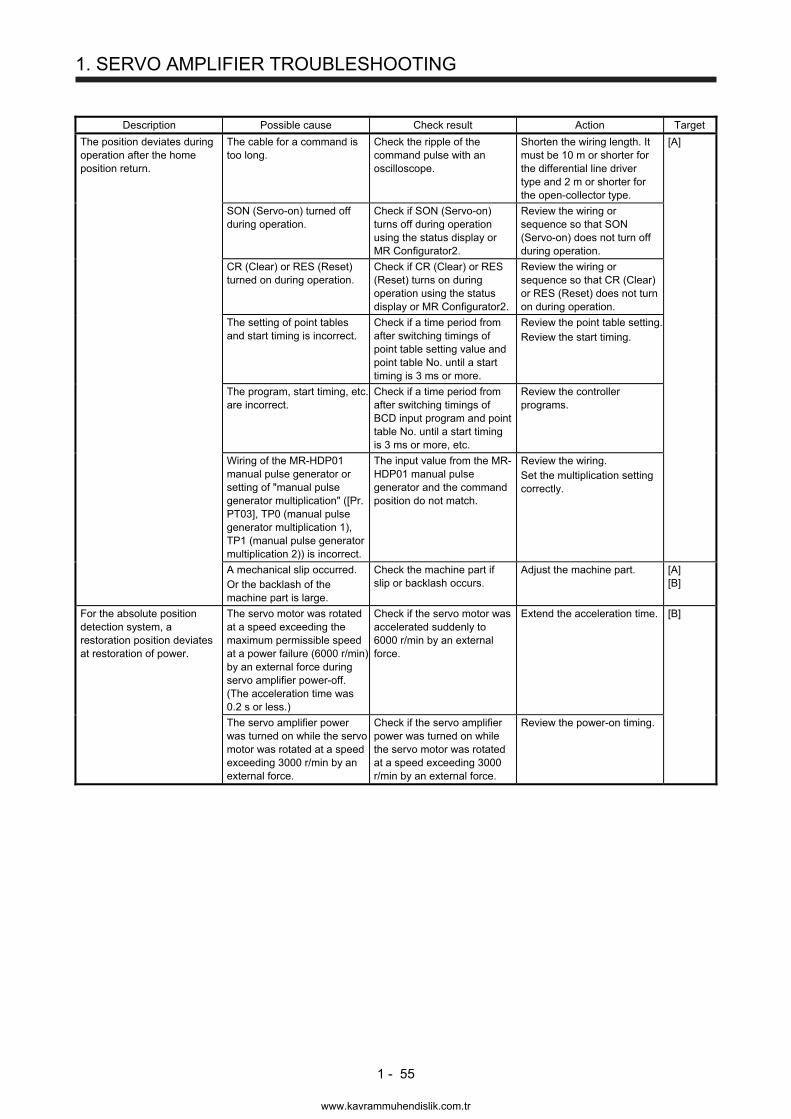
1. SERVO AMPLIFIER TROUBLESHOOTING
1 - 55
Description Possible cause Check result Action Target
The position deviates during operation after the home position return.
The cable for a command is too long.
Check the ripple of the command pulse with an oscilloscope.
Shorten the wiring length. It must be 10 m or shorter for the differential line driver type and 2 m or shorter for the open-collector type.
[A]
SON (Servo-on) turned off during operation.
Check if SON (Servo-on) turns off during operation using the status display or MR Configurator2.
Review the wiring or sequence so that SON (Servo-on) does not turn off during operation.
CR (Clear) or RES (Reset) turned on during operation.
Check if CR (Clear) or RES (Reset) turns on during operation using the status display or MR Configurator2.
Review the wiring or sequence so that CR (Clear) or RES (Reset) does not turn on during operation.
The setting of point tables and start timing is incorrect.
Check if a time period from after switching timings of point table setting value and point table No. until a start timing is 3 ms or more.
Review the point table setting.Review the start timing.
The program, start timing, etc. are incorrect.
Check if a time period from after switching timings of BCD input program and point table No. until a start timing is 3 ms or more, etc.
Review the controller programs.
Wiring of the MR-HDP01 manual pulse generator or setting of "manual pulse generator multiplication" ([Pr. PT03], TP0 (manual pulse generator multiplication 1), TP1 (manual pulse generator multiplication 2)) is incorrect.
The input value from the MR-HDP01 manual pulse generator and the command position do not match.
Review the wiring. Set the multiplication setting correctly.
A mechanical slip occurred. Or the backlash of the machine part is large.
Check the machine part if slip or backlash occurs.
Adjust the machine part. [A] [B]
For the absolute position detection system, a restoration position deviates at restoration of power.
The servo motor was rotated at a speed exceeding the maximum permissible speed at a power failure (6000 r/min) by an external force during servo amplifier power-off. (The acceleration time was 0.2 s or less.)
Check if the servo motor was accelerated suddenly to 6000 r/min by an external force.
Extend the acceleration time. [B]
The servo amplifier power was turned on while the servo motor was rotated at a speed exceeding 3000 r/min by an external force.
Check if the servo amplifier power was turned on while the servo motor was rotated at a speed exceeding 3000 r/min by an external force.
Review the power-on timing.
www.kavrammuhendislik.com.tr
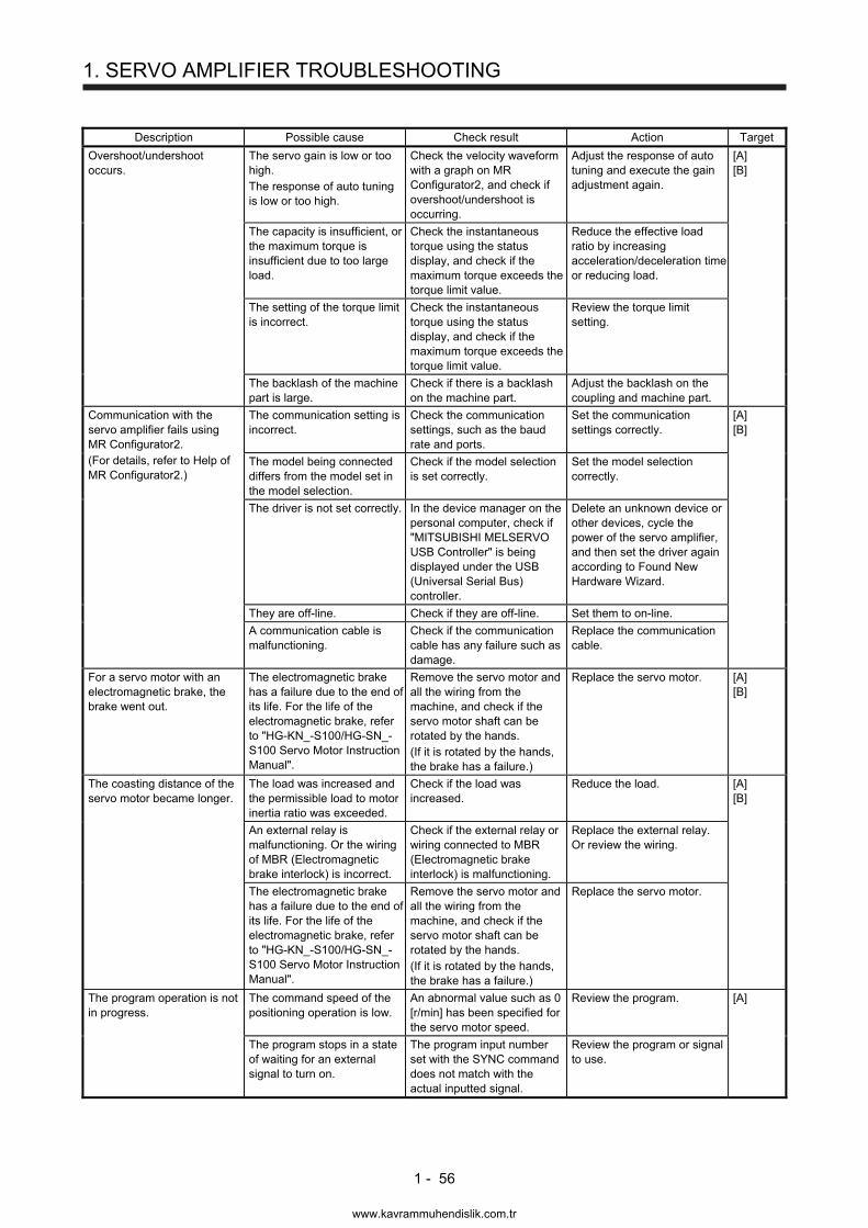
1. SERVO AMPLIFIER TROUBLESHOOTING
1 - 56
Description Possible cause Check result Action Target
Overshoot/undershoot occurs.
The servo gain is low or too high. The response of auto tuning is low or too high.
Check the velocity waveform with a graph on MR Configurator2, and check if overshoot/undershoot is occurring.
Adjust the response of auto tuning and execute the gain adjustment again.
[A] [B]
The capacity is insufficient, or the maximum torque is insufficient due to too large load.
Check the instantaneous torque using the status display, and check if the maximum torque exceeds the torque limit value.
Reduce the effective load ratio by increasing acceleration/deceleration time or reducing load.
The setting of the torque limit is incorrect.
Check the instantaneous torque using the status display, and check if the maximum torque exceeds the torque limit value.
Review the torque limit setting.
The backlash of the machine part is large.
Check if there is a backlash on the machine part.
Adjust the backlash on the coupling and machine part.
Communication with the servo amplifier fails using MR Configurator2. (For details, refer to Help of MR Configurator2.)
The communication setting is incorrect.
Check the communication settings, such as the baud rate and ports.
Set the communication settings correctly.
[A] [B]
The model being connected differs from the model set in the model selection.
Check if the model selection is set correctly.
Set the model selection correctly.
The driver is not set correctly. In the device manager on the personal computer, check if "MITSUBISHI MELSERVO USB Controller" is being displayed under the USB (Universal Serial Bus) controller.
Delete an unknown device or other devices, cycle the power of the servo amplifier, and then set the driver again according to Found New Hardware Wizard.
They are off-line. Check if they are off-line. Set them to on-line.
A communication cable is malfunctioning.
Check if the communication cable has any failure such as damage.
Replace the communication cable.
For a servo motor with an electromagnetic brake, the brake went out.
The electromagnetic brake has a failure due to the end of its life. For the life of the electromagnetic brake, refer to "HG-KN_-S100/HG-SN_-S100 Servo Motor Instruction Manual".
Remove the servo motor and all the wiring from the machine, and check if the servo motor shaft can be rotated by the hands. (If it is rotated by the hands, the brake has a failure.)
Replace the servo motor. [A] [B]
The coasting distance of the servo motor became longer.
The load was increased and the permissible load to motor inertia ratio was exceeded.
Check if the load was increased.
Reduce the load. [A] [B]
An external relay is malfunctioning. Or the wiring of MBR (Electromagnetic brake interlock) is incorrect.
Check if the external relay or wiring connected to MBR (Electromagnetic brake interlock) is malfunctioning.
Replace the external relay. Or review the wiring.
The electromagnetic brake has a failure due to the end of its life. For the life of the electromagnetic brake, refer to "HG-KN_-S100/HG-SN_-S100 Servo Motor Instruction Manual".
Remove the servo motor and all the wiring from the machine, and check if the servo motor shaft can be rotated by the hands. (If it is rotated by the hands, the brake has a failure.)
Replace the servo motor.
The program operation is not in progress.
The command speed of the positioning operation is low.
An abnormal value such as 0 [r/min] has been specified for the servo motor speed.
Review the program. [A]
The program stops in a state of waiting for an external signal to turn on.
The program input number set with the SYNC command does not match with the actual inputted signal.
Review the program or signal to use.
www.kavrammuhendislik.com.tr
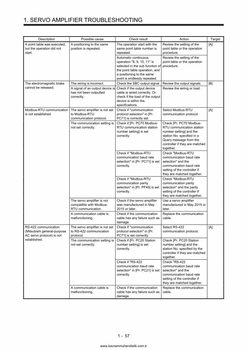
1. SERVO AMPLIFIER TROUBLESHOOTING
1 - 57
Description Possible cause Check result Action Target
A point table was executed, but the operation did not start.
A positioning to the same position is repeated.
The operation start with the same point table number is repeated.
Review the setting of the point table or the operation procedure.
[A]
Automatic continuous operation "8, 9, 10, 11" is selected in the sub function of the point table operation, and a positioning to the same point is endlessly repeated.
Review the setting of the point table or the operation procedure.
The electromagnetic brake cannot be released.
The wiring is incorrect. Check the SBC output signal. Review the output signals. [B]
A signal of an output device is has not been outputted correctly.
Check if the output device cable is wired correctly. Or check if the load of the output device is within the specifications.
Review the wiring or load.
Modbus-RTU communication is not established.
The servo amplifier is not set to Modbus-RTU communication protocol.
Check if "communication protocol selection" in [Pr. PC71] is correctly set.
Select Modbus-RTU communication protocol.
[A]
The communication setting is not set correctly.
Check if [Pr. PC70 Modbus-RTU communication station number setting] is set correctly.
Check [Pr. PC70 Modbus-RTU communication station number setting] and the station No. specified in a Query message from the controller if they are matched together.
Check if "Modbus-RTU communication baud rate selection" in [Pr. PC71] is set correctly.
Check "Modbus-RTU communication baud rate selection" and the communication baud rate setting of the controller if they are matched together.
Check if "Modbus-RTU communication parity selection" in [Pr. PF45] is set correctly.
Check "Modbus-RTU communication parity selection" and the parity setting of the controller if they are matched together.
The servo amplifier is not compatible with Modbus-RTU communication.
Check if the servo amplifier was manufactured in May 2015 or later.
Use a servo amplifier manufactured in May 2015 or later.
A communication cable is malfunctioning.
Check if the communication cable has any failure such as damage.
Replace the communication cable.
RS-422 communication (Mitsubishi general-purpose AC servo protocol) is not established.
The servo amplifier is not set to RS-422 communication protocol.
Check if "communication protocol selection" in [Pr. PC71] is set correctly.
Select RS-422 communication protocol.
[A]
The communication setting is not set correctly.
Check if [Pr. PC20 Station number setting] is set correctly.
Check [Pr. PC20 Station number setting] and the station No. specified by the controller if they are matched together.
Check if "RS-422 communication baud rate selection" in [Pr. PC21] is set correctly.
Check "RS-422 communication baud rate selection" and the communication baud rate setting of the controller if they are matched together.
A communication cable is malfunctioning.
Check if the communication cable has any failure such as damage.
Replace the communication cable.
www.kavrammuhendislik.com.tr
1. SERVO AMPLIFIER TROUBLESHOOTING
1 - 58
MEMO
www.kavrammuhendislik.com.tr
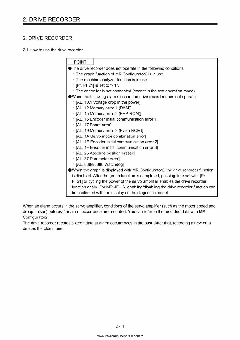
2. DRIVE RECORDER
2 - 1
2. DRIVE RECORDER
2.1 How to use the drive recorder
POINT
The drive recorder does not operate in the following conditions.
The graph function of MR Configurator2 is in use.
The machine analyzer function is in use.
[Pr. PF21] is set to "- 1".
The controller is not connected (except in the test operation mode).
When the following alarms occur, the drive recorder does not operate.
[AL. 10.1 Voltage drop in the power]
[AL. 12 Memory error 1 (RAM)]
[AL. 15 Memory error 2 (EEP-ROM)]
[AL. 16 Encoder initial communication error 1]
[AL. 17 Board error]
[AL. 19 Memory error 3 (Flash-ROM)]
[AL. 1A Servo motor combination error]
[AL. 1E Encoder initial communication error 2]
[AL. 1F Encoder initial communication error 3]
[AL. 25 Absolute position erased]
[AL. 37 Parameter error]
[AL. 888/88888 Watchdog]
When the graph is displayed with MR Configurator2, the drive recorder function is disabled. After the graph function is completed, passing time set with [Pr. PF21] or cycling the power of the servo amplifier enables the drive recorder function again. For MR-JE-_A, enabling/disabling the drive recorder function can be confirmed with the display (in the diagnostic mode).
When an alarm occurs in the servo amplifier, conditions of the servo amplifier (such as the motor speed and droop pulses) before/after alarm occurrence are recorded. You can refer to the recorded data with MR Configurator2. The drive recorder records sixteen data at alarm occurrences in the past. After that, recording a new data deletes the oldest one.
www.kavrammuhendislik.com.tr

2. DRIVE RECORDER
2 - 2
(1) Trigger setting of the drive recorder
To operate the drive recorder only for a specified alarm, set "Drive recorder arbitrary alarm trigger setting" ([Pr. PA23]). For the settings, refer to explanations for [Pr. PA23] in each instruction manual. When "Drive recorder arbitrary alarm trigger setting" ([Pr. PA23]) is set to "0 0 0 0" (initial value), the drive recorder operates for alarms expect the ones described in above POINT.
(2) Recordable data by drive recorder
When "Drive recorder arbitrary alarm trigger setting" ([Pr. PA23]) is set to "0 0 0 0" (initial value), the drive recorder records data described in the standard column in table 2.1 or 2.2 for all alarms. When you set an alarm in table 2.1 or 2.2 to [Pr. PA23], each data described in the alarm column is recorded. When you set an alarm unlisted in table 2.1 and 2.2, data described in the standard column are recorded. Refer to table 2.3 for descriptions of each signal.
(3) When the servo amplifier power is turned off during data storage (immediately after alarm occurrence),
data at alarm occurrence may not be recorded normally. When the following alarms occur, data at alarm occurrence may not be recorded depending on its circumstances.
[AL. 13 Clock error]
[AL. 14 Control process error]
[AL. 34 SSCNET receive error 1]
[AL. 36 SSCNET receive error 2]
www.kavrammuhendislik.com.tr
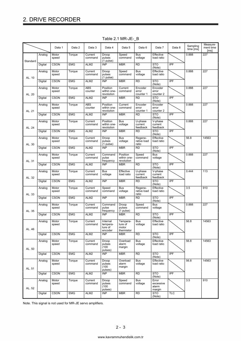
2. DRIVE RECORDER
2 - 3
Table 2.1 MR-JE-_B
Data 1 Data 2 Data 3 Data 4 Data 5 Data 6 Data 7 Data 8 Sampling time [ms]
Measure-ment time
[ms]
Standard
Analog Motor speed
Torque Current command
Droop pulses (1 pulse)
Speed command
Bus voltage
Effective load ratio
0.888 227
Digital CSON EMG ALM2 INP MBR RD STO (Note)
IPF
AL. 10
Analog Motor speed
Torque Current command
Droop pulses (1 pulse)
Speed command
Bus voltage
Effective load ratio
0.888 227
Digital CSON EMG ALM2 INP MBR RD STO (Note)
IPF
AL. 20
Analog Motor speed
Torque ABS counter
Position within one-revolution
Current command
Encoder error counter 1
Encoder error counter 2
0.888 227
Digital CSON EMG ALM2 INP MBR RD STO (Note)
IPF
AL. 21
Analog Motor speed
Torque ABS counter
Position within one-revolution
Current command
Encoder error counter 1
Encoder error counter 2
0.888 227
Digital CSON EMG ALM2 INP MBR RD STO (Note)
IPF
AL. 24
Analog Motor speed
Torque Current command
Position within one-revolution
Bus voltage
U-phase current feedback
V-phase current feedback
0.888 227
Digital CSON EMG ALM2 INP MBR RD STO (Note)
IPF
AL. 30
Analog Motor speed
Torque Current command
Droop pulses (1 pulse)
Bus voltage
Regene-rative load ratio
Effective load ratio
56.8 14563
Digital CSON EMG ALM2 INP MBR RD STO (Note)
IPF
AL. 31
Analog Motor speed
Torque Current command
Command pulse frequency
Position within one-revolution
Speed command
Bus voltage
0.888 227
Digital CSON EMG ALM2 INP MBR RD STO (Note)
IPF
AL. 32
Analog Motor speed
Torque Current command
Bus voltage
Effective load ratio
U-phase current feedback
V-phase current feedback
0.444 113
Digital CSON EMG ALM2 INP MBR RD STO (Note)
IPF
AL. 33
Analog Motor speed
Torque Current command
Speed command
Bus voltage
Regene-rative load ratio
Effective load ratio
3.5 910
Digital CSON EMG ALM2 INP MBR RD STO (Note)
IPF
AL. 35
Analog Motor speed
Torque Current command
Command pulse frequency
Droop pulses (1 pulse)
Speed command
Bus voltage
0.888 227
Digital CSON EMG ALM2 INP MBR RD STO (Note)
IPF
AL. 46
Analog Motor speed
Torque Current command
Internal tempera-ture of encoder
Tempera-ture of motor thermistor
Bus voltage
Effective load ratio
56.8 14563
Digital CSON EMG ALM2 INP MBR RD STO (Note)
IPF
AL. 50
Analog Motor speed
Torque Current command
Droop pulses (100 pulses)
Overload alarm margin
Bus voltage
Effective load ratio
56.8 14563
Digital CSON EMG ALM2 INP MBR RD STO (Note)
IPF
AL. 51
Analog Motor speed
Torque Current command
Droop pulses (100 pulses)
Overload alarm margin
Bus voltage
Effective load ratio
56.8 14563
Digital CSON EMG ALM2 INP MBR RD STO (Note)
IPF
AL. 52
Analog Motor speed
Torque Current command
Droop pulses (100 pulses)
Speed command
Bus voltage
Error excessive alarm margin
3.5 910
Digital CSON EMG ALM2 INP MBR RD STO (Note)
TLC
Note. This signal is not used for MR-JE servo amplifiers.
www.kavrammuhendislik.com.tr

2. DRIVE RECORDER
2 - 4
Table 2.2 MR-JE-_A
Data 1 Data 2 Data 3 Data 4 Data 5 Data 6 Data 7 Data 8 Sampling time [ms]
Measure-ment time
[ms]
Standard
Analog Motor speed
Torque Current command
Droop pulses (1 pulse)
Speed command
Bus voltage
Effective load ratio
0.888 227
Digital SON EM2/EM1 ALM2 INP MBR RD STO (Note)
IPF
AL. 10
Analog Motor speed
Torque Current command
Droop pulses (1 pulse)
Speed command
Bus voltage
Effective load ratio
0.888 227
Digital SON EM2/EM1 ALM2 INP MBR RD STO (Note)
IPF
AL. 20
Analog Motor speed
Torque ABS counter
Position within one-revolution
Current command
Encoder error counter 1
Encoder error counter 2
0.888 227
Digital SON EM2/EM1 ALM2 INP MBR RD STO (Note)
IPF
AL. 21
Analog Motor speed
Torque ABS counter
Position within one-revolution
Current command
Encoder error counter 1
Encoder error counter 2
0.888 227
Digital SON EM2/EM1 ALM2 INP MBR RD STO (Note)
IPF
AL. 24
Analog Motor speed
Torque Current command
Position within one-revolution
Bus voltage
U-phase current feedback
V-phase current feedback
0.888 227
Digital SON EM2/EM1 ALM2 INP MBR RD STO (Note)
IPF
AL. 30
Analog Motor speed
Torque Current command
Droop pulses (1 pulse)
Bus voltage
Regene-rative load ratio
Effective load ratio
56.8 14563
Digital SON EM2/EM1 ALM2 INP MBR RD STO (Note)
IPF
AL. 31
Analog Motor speed
Torque Current command
Command pulse frequency
Position within one-revolution
Speed command
Bus voltage
0.888 227
Digital SON EM2/EM1 ALM2 INP MBR RD STO (Note)
IPF
AL. 32
Analog Motor speed
Torque Current command
Bus voltage
Effective load ratio
U-phase current feedback
V-phase current feedback
0.444 113
Digital SON EM2/EM1 ALM2 INP MBR RD STO (Note)
IPF
AL. 33
Analog Motor speed
Torque Current command
Speed command
Bus voltage
Regene-rative load ratio
Effective load ratio
3.5 910
Digital SON EM2/EM1 ALM2 INP MBR RD STO (Note)
IPF
AL. 35
Analog Motor speed
Torque Current command
Command pulse frequency
Droop pulses (1 pulse)
Speed command
Bus voltage
0.888 227
Digital SON EM2/EM1 ALM2 INP MBR RD STO (Note)
IPF
AL. 46
Analog Motor speed
Torque Current command
Internal tempera-ture of encoder
Tempera-ture of motor thermistor
Bus voltage
Effective load ratio
56.8 14563
Digital SON EM2/EM1 ALM2 INP MBR RD STO (Note)
IPF
AL. 50
Analog Motor speed
Torque Current command
Droop pulses (100 pulses)
Overload alarm margin
Bus voltage
Effective load ratio
56.8 14563
Digital SON EM2/EM1 ALM2 INP MBR RD STO (Note)
IPF
AL. 51
Analog Motor speed
Torque Current command
Droop pulses (100 pulses)
Overload alarm margin
Bus voltage
Effective load ratio
56.8 14563
Digital SON EM2/EM1 ALM2 INP MBR RD STO (Note)
IPF
AL. 52
Analog Motor speed
Torque Current command
Droop pulses (100 pulses)
Speed command
Bus voltage
Error excessive alarm margin
3.5 910
Digital SON EM2/EM1 ALM2 INP MBR RD STO (Note)
TLC
Note. This signal is not used for MR-JE servo amplifiers.
www.kavrammuhendislik.com.tr

2. DRIVE RECORDER
2 - 5
Table 2.3 Signal explanations
Signal name Description Unit
Ana
log Motor speed The servo motor speed is displayed. [r/min]
Torque The servo motor torque is displayed. The value of torque occurring is displayed in real time by considering a rated torque as 100%.
[0.1%]
Current command This indicates the current command applying to the servo motor. [0.1%]
Droop pulses (1 pulse)
This indicates the number of droop pulses in the deviation counter in units of 1 pulse. [pulse]
Droop pulses (100 pulses)
This indicates the number of droop pulses in the deviation counter in units of 100 pulses. [100 pulses]
Speed command This indicates the speed command applying to the servo motor. [r/min]
Bus voltage This indicates the bus voltage at the converter of the servo amplifier. [V]
Effective load ratio The continuous effective load torque is displayed. This indicates the effective value for past 15 seconds.
[0.1%]
ABS counter The travel distance from the home position is displayed as multi-revolution counter value of the absolution position encoder in the absolution position detection system.
[rev]
Position within one-revolution
The position within one revolution is displayed in units of encoder pulses. [16 pulses]
Encoder error counter 1
This indicates the cumulative number of errors during a communication with the encoder. [times]
Encoder error counter 2
The same as encoder error counter 1 [times]
U-phase current feedback
This indicates the U-phase current value applying to the servo motor in internal units.
V-phase current feedback
This indicates the V-phase current value applying to the servo motor in internal units.
Regenerative load ratio
The ratio of regenerative power to permissible regenerative power is displayed in percentage.
[0.1%]
Command pulse frequency
This indicates the command pulse frequency. [1.125 kpps]
Internal temperature of encoder
The encoder inside temperature detected by the encoder is displayed. [˚C]
Temperature of motor thermistor
The thermistor temperature is displayed for the rotary servo motor with a thermistor. [˚C]
Overload alarm margin
This indicates margins to the levels which trigger [AL. 50 Overload 1] and [AL. 51 Overload 2] in percentage. When the value becomes 0%, the overload alarm occurs.
[0.1%]
Error excessive alarm margin
This indicates a margin to the level which triggers the error excessive alarm in units of encoder pulses. When the value becomes 0 pulse, the error excessive alarm occurs.
[pulse]
Dig
ital CSON This indicates the status of the servo-on signal from the controller.
SON This indicates the SON status of the external input signal.
EMG This indicates the status of the emergency stop input.
EM2/EM1 This indicates the EM2/EM1 status of the external input signal.
ALM2 This turns on when an alarm is detected in the servo amplifier. This changes faster than ALM of the external output signal.
INP This indicates the INP status of the external output signal.
MBR This indicates the MBR status of the external output signal.
RD This indicates the RD status of the external output signal.
STO (Note) This indicates the STO status of the external input signal.
IPF This turns on when an instantaneous power failure occurs. Note. This signal is not used for MR-JE servo amplifiers.
www.kavrammuhendislik.com.tr
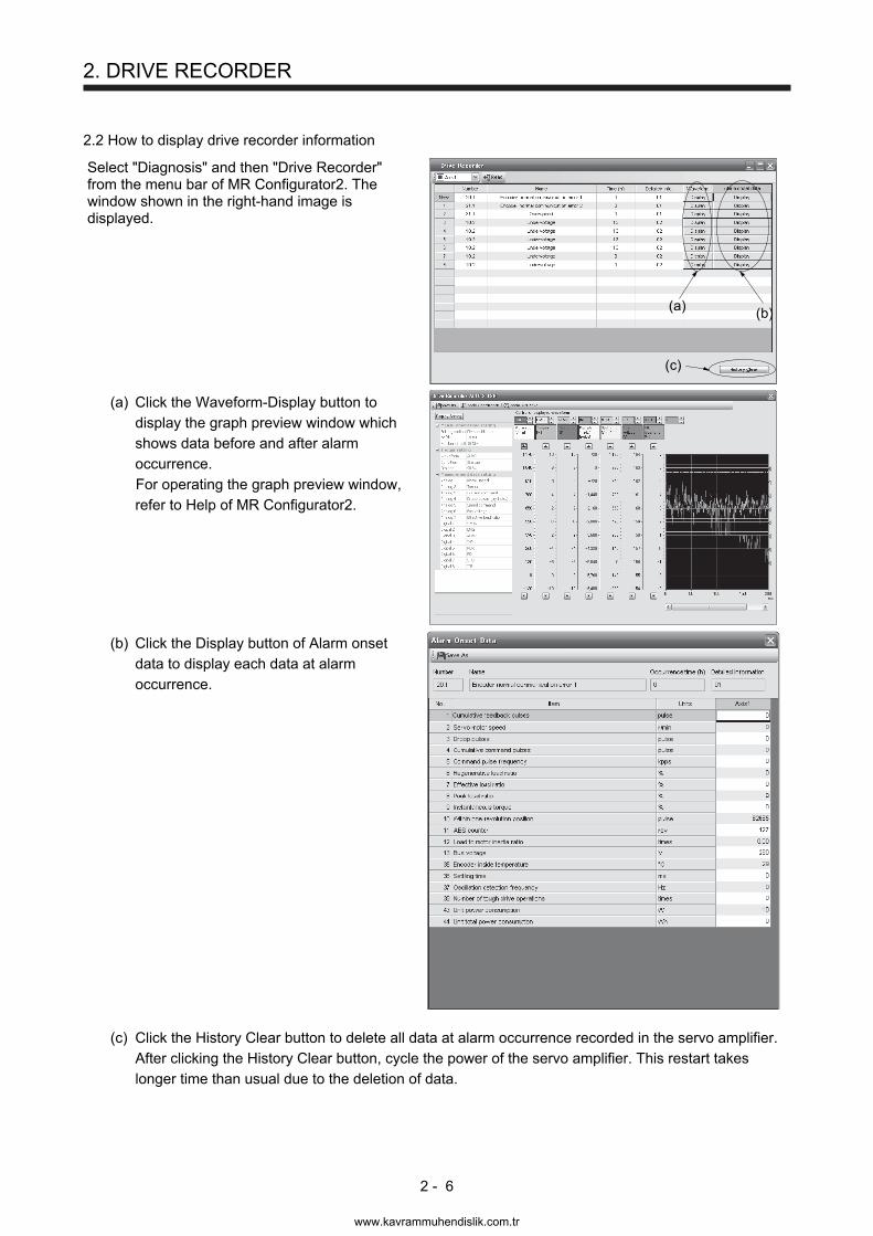
2. DRIVE RECORDER
2 - 6
2.2 How to display drive recorder information
Select "Diagnosis" and then "Drive Recorder" from the menu bar of MR Configurator2. The window shown in the right-hand image is displayed.
(b)(a)
(c)
(a) Click the Waveform-Display button to display the graph preview window which shows data before and after alarm occurrence. For operating the graph preview window, refer to Help of MR Configurator2.
(b) Click the Display button of Alarm onset data to display each data at alarm occurrence.
(c) Click the History Clear button to delete all data at alarm occurrence recorded in the servo amplifier.
After clicking the History Clear button, cycle the power of the servo amplifier. This restart takes longer time than usual due to the deletion of data.
www.kavrammuhendislik.com.tr
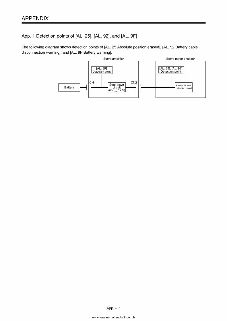
APPENDIX
App. - 1
App. 1 Detection points of [AL. 25], [AL. 92], and [AL. 9F]
The following diagram shows detection points of [AL. 25 Absolute position erased], [AL. 92 Battery cable disconnection warning], and [AL. 9F Battery warning].
[AL. 9F]Detection point
[AL. 25], [AL. 92]Detection point
Battery
Servo amplifier Servo motor encoder
CN4Position/speeddetection circuit
Step-downcircuit
(6 V 3.4 V)
CN2
www.kavrammuhendislik.com.tr
REVISION
*The manual number is given on the bottom left of the back cover. Print Data *Manual Number Revision
Nov. 2014 SH(NA)030166-A First edition
Mar. 2015 SH(NA)030166-B The contents of Modbus-RTU and simple cam are added.
Section 1.2
Section 1.3
Section 1.4
Section 1.6
[AL. 8A.2], [AL. 8E.6], [AL. 8E.7], and [AL. 8E.8] are added.
[AL. F5_] and [AL. F6_] are added.
[AL. 30.1] (4) is partially changed.
[AL. 8A] is partially changed.
[AL. 8A.2] is added.
[AL. 8E] is partially changed.
[AL. 8E.6] and [AL. 8E.7] are added.
[AL. 96.1] and [AL. 96.2] are partially changed.
[AL. E7] is partially changed.
[AL. F5] and [AL. F6] are added.
A part of "The servo motor does not operate." is changed.
A part of "The servo motor speed does not accelerate. Or the servo
motor speed accelerates too much." is changed.
A part of "The position deviates during operation after the home
position return." is changed.
A part of "Communication with the servo amplifier fails using MR
Configurator2." is changed.
"Modbus-RTU communication is not established." is added.
"RS-422 communication (Mitsubishi general-purpose AC servo
protocol) is not established." is added.
This manual confers no industrial property rights or any rights of any other kind, nor does it confer any patent licenses. Mitsubishi Electric Corporation cannot be held responsible for any problems involving industrial property rights which may occur as a result of using the contents noted in this manual.
2014 MITSUBISHI ELECTRIC CORPORATION
www.kavrammuhendislik.com.tr
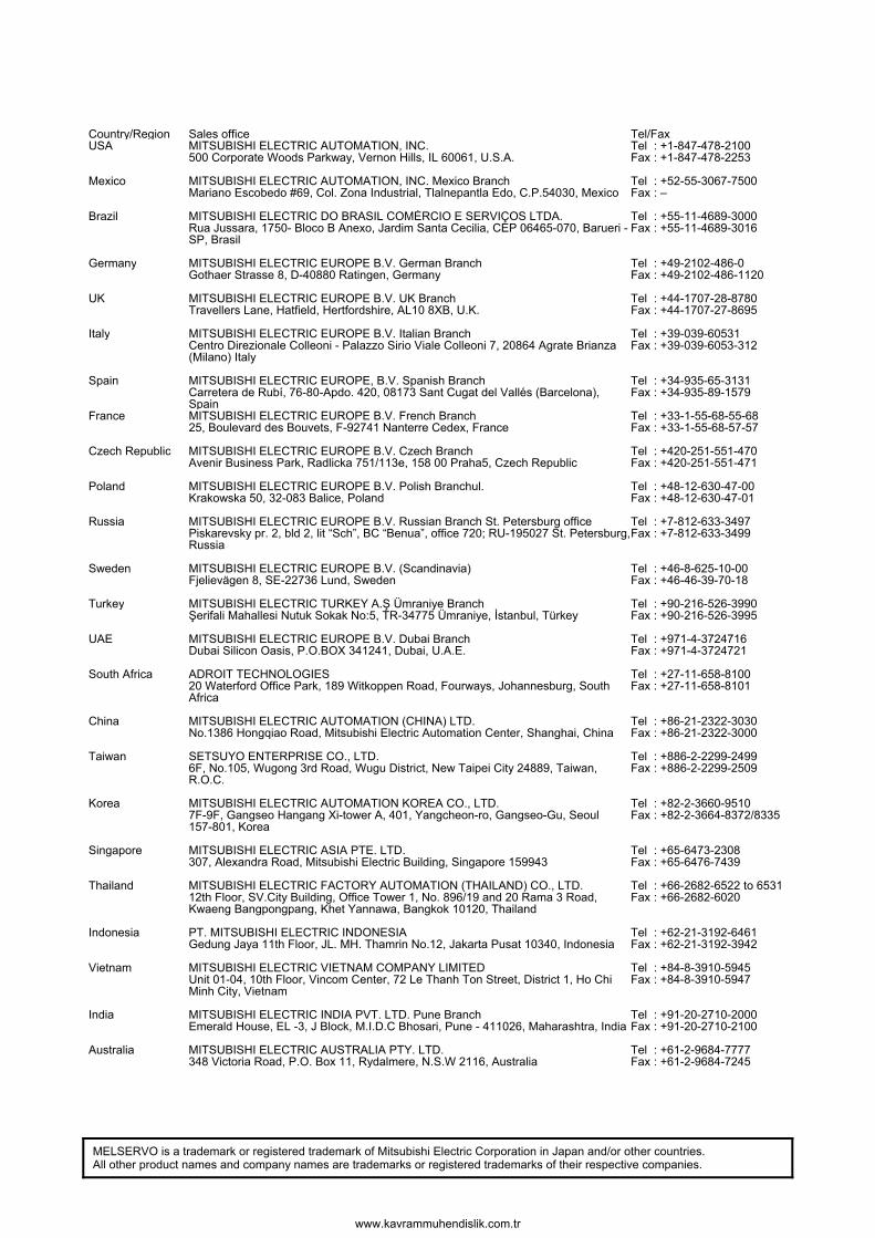
MELSERVO is a trademark or registered trademark of Mitsubishi Electric Corporation in Japan and/or other countries. All other product names and company names are trademarks or registered trademarks of their respective companies.
Country/Region Sales office Tel/Fax USA MITSUBISHI ELECTRIC AUTOMATION, INC.
500 Corporate Woods Parkway, Vernon Hills, IL 60061, U.S.A.
Tel Fax
: +1-847-478-2100: +1-847-478-2253
Mexico MITSUBISHI ELECTRIC AUTOMATION, INC. Mexico BranchMariano Escobedo #69, Col. Zona Industrial, Tlalnepantla Edo, C.P.54030, Mexico
Tel Fax
: +52-55-3067-7500: –
Brazil MITSUBISHI ELECTRIC DO BRASIL COMÉRCIO E SERVIÇOS LTDA. Rua Jussara, 1750- Bloco B Anexo, Jardim Santa Cecilia, CEP 06465-070, Barueri - SP, Brasil
Tel Fax
: +55-11-4689-3000: +55-11-4689-3016
Germany MITSUBISHI ELECTRIC EUROPE B.V. German BranchGothaer Strasse 8, D-40880 Ratingen, Germany
Tel Fax
: +49-2102-486-0: +49-2102-486-1120
UK MITSUBISHI ELECTRIC EUROPE B.V. UK BranchTravellers Lane, Hatfield, Hertfordshire, AL10 8XB, U.K.
Tel Fax
: +44-1707-28-8780: +44-1707-27-8695
Italy MITSUBISHI ELECTRIC EUROPE B.V. Italian BranchCentro Direzionale Colleoni - Palazzo Sirio Viale Colleoni 7, 20864 Agrate Brianza (Milano) Italy
Tel Fax
: +39-039-60531: +39-039-6053-312
Spain MITSUBISHI ELECTRIC EUROPE, B.V. Spanish BranchCarretera de Rubí, 76-80-Apdo. 420, 08173 Sant Cugat del Vallés (Barcelona), Spain
Tel Fax
: +34-935-65-3131: +34-935-89-1579
France MITSUBISHI ELECTRIC EUROPE B.V. French Branch25, Boulevard des Bouvets, F-92741 Nanterre Cedex, France
Tel Fax
: +33-1-55-68-55-68: +33-1-55-68-57-57
Czech Republic MITSUBISHI ELECTRIC EUROPE B.V. Czech BranchAvenir Business Park, Radlicka 751/113e, 158 00 Praha5, Czech Republic
Tel Fax
: +420-251-551-470: +420-251-551-471
Poland MITSUBISHI ELECTRIC EUROPE B.V. Polish Branchul. Krakowska 50, 32-083 Balice, Poland
Tel Fax
: +48-12-630-47-00: +48-12-630-47-01
Russia MITSUBISHI ELECTRIC EUROPE B.V. Russian Branch St. Petersburg officePiskarevsky pr. 2, bld 2, lit “Sch”, BC “Benua”, office 720; RU-195027 St. Petersburg, Russia
Tel Fax
: +7-812-633-3497: +7-812-633-3499
Sweden MITSUBISHI ELECTRIC EUROPE B.V. (Scandinavia) Fjelievägen 8, SE-22736 Lund, Sweden
Tel Fax
: +46-8-625-10-00: +46-46-39-70-18
Turkey MITSUBISHI ELECTRIC TURKEY A.Ş Ümraniye BranchŞerifali Mahallesi Nutuk Sokak No:5, TR-34775 Ümraniye, İstanbul, Türkey
Tel Fax
: +90-216-526-3990: +90-216-526-3995
UAE MITSUBISHI ELECTRIC EUROPE B.V. Dubai Branch Dubai Silicon Oasis, P.O.BOX 341241, Dubai, U.A.E.
Tel Fax
: +971-4-3724716: +971-4-3724721
South Africa ADROIT TECHNOLOGIES 20 Waterford Office Park, 189 Witkoppen Road, Fourways, Johannesburg, South Africa
Tel Fax
: +27-11-658-8100: +27-11-658-8101
China MITSUBISHI ELECTRIC AUTOMATION (CHINA) LTD.No.1386 Hongqiao Road, Mitsubishi Electric Automation Center, Shanghai, China
Tel Fax
: +86-21-2322-3030: +86-21-2322-3000
Taiwan SETSUYO ENTERPRISE CO., LTD.6F, No.105, Wugong 3rd Road, Wugu District, New Taipei City 24889, Taiwan, R.O.C.
Tel Fax
: +886-2-2299-2499: +886-2-2299-2509
Korea MITSUBISHI ELECTRIC AUTOMATION KOREA CO., LTD. 7F-9F, Gangseo Hangang Xi-tower A, 401, Yangcheon-ro, Gangseo-Gu, Seoul 157-801, Korea
Tel Fax
: +82-2-3660-9510: +82-2-3664-8372/8335
Singapore MITSUBISHI ELECTRIC ASIA PTE. LTD.307, Alexandra Road, Mitsubishi Electric Building, Singapore 159943
Tel Fax
: +65-6473-2308: +65-6476-7439
Thailand MITSUBISHI ELECTRIC FACTORY AUTOMATION (THAILAND) CO., LTD.12th Floor, SV.City Building, Office Tower 1, No. 896/19 and 20 Rama 3 Road, Kwaeng Bangpongpang, Khet Yannawa, Bangkok 10120, Thailand
Tel Fax
: +66-2682-6522 to 6531: +66-2682-6020
Indonesia PT. MITSUBISHI ELECTRIC INDONESIAGedung Jaya 11th Floor, JL. MH. Thamrin No.12, Jakarta Pusat 10340, Indonesia
Tel Fax
: +62-21-3192-6461: +62-21-3192-3942
Vietnam MITSUBISHI ELECTRIC VIETNAM COMPANY LIMITED Unit 01-04, 10th Floor, Vincom Center, 72 Le Thanh Ton Street, District 1, Ho Chi Minh City, Vietnam
Tel Fax
: +84-8-3910-5945: +84-8-3910-5947
India MITSUBISHI ELECTRIC INDIA PVT. LTD. Pune BranchEmerald House, EL -3, J Block, M.I.D.C Bhosari, Pune - 411026, Maharashtra, India
Tel Fax
: +91-20-2710-2000: +91-20-2710-2100
Australia MITSUBISHI ELECTRIC AUSTRALIA PTY. LTD.348 Victoria Road, P.O. Box 11, Rydalmere, N.S.W 2116, Australia
Tel Fax
: +61-2-9684-7777: +61-2-9684-7245
www.kavrammuhendislik.com.tr
Warranty
1. Warranty period and coverage We will repair any failure or defect hereinafter referred to as "failure" in our FA equipment hereinafter referred to as the "Product" arisen during warranty period at no charge due to causes for which we are responsible through the distributor from which you purchased the Product or our service provider. However, we will charge the actual cost of dispatching our engineer for an on-site repair work on request by customer in Japan or overseas countries. We are not responsible for any on-site readjustment and/or trial run that may be required after a defective unit are repaired or replaced.
[Term]
The term of warranty for Product is twelve (12) months after your purchase or delivery of the Product to a place designated by you or eighteen (18) months from the date of manufacture whichever comes first (“Warranty Period”). Warranty period for repaired Product cannot exceed beyond the original warranty period before any repair work.
[Limitations]
(1) You are requested to conduct an initial failure diagnosis by yourself, as a general rule. It can also be carried out by us or our service company upon your request and the actual cost will be charged. However, it will not be charged if we are responsible for the cause of the failure.
(2) This limited warranty applies only when the condition, method, environment, etc. of use are in compliance with the terms and
conditions and instructions that are set forth in the instruction manual and user manual for the Product and the caution label affixed to the Product.
(3) Even during the term of warranty, the repair cost will be charged on you in the following cases;
(i) a failure caused by your improper storing or handling, carelessness or negligence, etc., and a failure caused by your
hardware or software problem
(ii) a failure caused by any alteration, etc. to the Product made on your side without our approval
(iii) a failure which may be regarded as avoidable, if your equipment in which the Product is incorporated is equipped with a
safety device required by applicable laws and has any function or structure considered to be indispensable according to a common sense in the industry
(iv) a failure which may be regarded as avoidable if consumable parts designated in the instruction manual, etc. are duly
maintained and replaced
(v) any replacement of consumable parts (battery, fan, smoothing capacitor, etc.)
(vi) a failure caused by external factors such as inevitable accidents, including without limitation fire and abnormal fluctuation of
voltage, and acts of God, including without limitation earthquake, lightning and natural disasters
(vii) a failure generated by an unforeseeable cause with a scientific technology that was not available at the time of the shipment
of the Product from our company
(viii) any other failures which we are not responsible for or which you acknowledge we are not responsible for
2. Term of warranty after the stop of production (1) We may accept the repair at charge for another seven (7) years after the production of the product is discontinued. The
announcement of the stop of production for each model can be seen in our Sales and Service, etc.
(2) Please note that the Product (including its spare parts) cannot be ordered after its stop of production.
3. Service in overseas countries
Our regional FA Center in overseas countries will accept the repair work of the Product. However, the terms and conditions of the repair work may differ depending on each FA Center. Please ask your local FA center for details.
4. Exclusion of responsibility for compensation against loss of opportunity, secondary loss, etc.
Whether under or after the term of warranty, we assume no responsibility for any damages arisen from causes for which we are not responsible, any losses of opportunity and/or profit incurred by you due to a failure of the Product, any damages, secondary damages or compensation for accidents arisen under a specific circumstance that are foreseen or unforeseen by our company, any damages to products other than the Product, and also compensation for any replacement work, readjustment, start-up test run of local machines and the Product and any other operations conducted by you.
5. Change of Product specifications
Specifications listed in our catalogs, manuals or technical documents may be changed without notice.
6. Application and use of the Product (1) For the use of our General-Purpose AC Servo, its applications should be those that may not result in a serious damage even if any
failure or malfunction occurs in General-Purpose AC Servo, and a backup or fail-safe function should operate on an external system to General-Purpose AC Servo when any failure or malfunction occurs.
(2) Our General-Purpose AC Servo is designed and manufactured as a general purpose product for use at general industries.
Therefore, applications substantially influential on the public interest for such as atomic power plants and other power plants of electric power companies, and also which require a special quality assurance system, including applications for railway companies and government or public offices are not recommended, and we assume no responsibility for any failure caused by these applications when used In addition, applications which may be substantially influential to human lives or properties for such as airlines, medical treatments, railway service, incineration and fuel systems, man-operated material handling equipment, entertainment machines, safety machines, etc. are not recommended, and we assume no responsibility for any failure caused by these applications when used. We will review the acceptability of the abovementioned applications, if you agree not to require a specific quality for a specific application. Please contact us for consultation.
SH(NA)030166-B
www.kavrammuhendislik.com.tr

SH (NA) 030166-B (1503) MEE Printed in Japan Specifications are subject to change without notice. This Instruction Manual uses recycled paper.
MODEL
MODELCODE
General-Purpose AC Servo
ME
LS
ER
VO
-JE S
ervo am
plifier IN
ST
RU
CT
ION
MA
NU
AL
(TR
OU
BL
E S
HO
OT
ING
)
HEAD OFFICE : TOKYO BLDG MARUNOUCHI TOKYO 100-8310
MELSERVO-JE Servo amplifierINSTRUCTION MANUAL (TROUBLE SHOOTING)
1CW710
MR-JE INSTRUCTIONMANUAL(TROUBLESHOOTING)
BB
www.kavrammuhendislik.com.tr