gasketed joint pvc pressure pipe installation guide
TRANSCRIPT
INSTALLATION GUIDE FOR
GASKETED JOINTPVC PRESSURE PIPE
2 UNI BELL PVC PIPE ASSOCIATION WWW.UNI BELL.ORG
PRESSURE PIPETABLE OF CONTENTSIntroduc on 3
Receiving 3
Unloading and Handling 4-5
Storage 6
Trenching 7
De-Watering 8
Field Cu ng 8
Lowering Pipe into the Trench 9
Cleaning and Inspec on 9
Lubrica on 10
Joint Assembly 10-11
Installing Pipe through Casings 12
Installa on of Fi ngs and Valves 12
Tracer Wire 12
Trench Construc on 13
Founda on 13
Bedding 14
Haunching 14
Ini al Backfi ll 15
Final Backfi ll 15
Compac ng the Backfi ll 16
Overnight Precau ons 16
Acceptance Tes ng 16-18
Special Considera ons 18
Checklist 19
Uni-Bell Literature 20
Members 21
3INSTALLATION GUIDE FOR PVC PRESSURE PIPE
PRESSURE PIPEINTRODUCTION:This document has been developed by the Uni-Bell PVC Pipe Associa on for use as a fi eld installa on guide. General informa on regarding the correct installa on of gasketed-joint PVC pressure pipe is included. Relevant product standards are:
• American Water Works Associa on (AWWA) C900 “Standard for Polyvinyl Chloride (PVC) Pressure Pipe and Fabricated Fi ngs, 4 in. through 12 in., for Water Distribu on”
• AWWA C905 “Standard for Polyvinyl Chloride (PVC) Pressure Pipe and Fabricated Fi ngs, 14 in. through 48 in., for Water Transmission and Distribu on”
• AWWA C907 “Standard for Injec on-Molded Polyvinyl Chloride (PVC) Pressure Fi ngs, 4 in. through 12 in., for Water, Wastewater, and Reclaimed Water Service”
• AWWA C909 “Standard for Molecularly Oriented Polyvinyl Chloride (PVCO) Pressure Pipe, 4 in. through 24 in., for Water, Wastewater, and Reclaimed Water Service”
For more detailed informa on, consult the pipe manufacturer or refer to AWWA C605 “Standard for Underground Installa on of PVC and PVCO Pressure Pipe and Fi ngs,” and AWWA Manual M23 “PVC Pipe – Design and Installa on.” The Handbook of PVC Pipe: Design and Construc on provides addi onal guidance on PVC pipe design and installa on. For informa on on this publica on, please contact Uni-Bell.
The Uni-Bell PVC Pipe Associa on, formed in 1971, funds PVC pipe research and development, provides technical service and support, develops recommended standards, and promotes proper use of PVC pipe with gasketed joints.
Uni-Bell members are manufacturers who are dedicated to producing high quality PVC pipe products for the industry.
The statements contained in this installa on guide are those of the Uni-Bell PVC Pipe Associa on and are not warran es, nor are they intended to be warran es. Inquiries for informa on on specifi c products, their a ributes and recommended uses, and the manufacturer’s warranty should be directed to member companies.
RECEIVING:When a load of pipe arrives at the job site, it is your responsibility to check it thoroughly. If possible, inspect each piece for damage. Check quan es against the shipping list. Note that once the pipe leaves the manufacturer’s plant, it becomes the property of the trucker. Any damaged or missing items must be documented on the bill of lading. Set aside any damaged items and no fy the shipper.
4 UNI BELL PVC PIPE ASSOCIATION WWW.UNI BELL.ORG
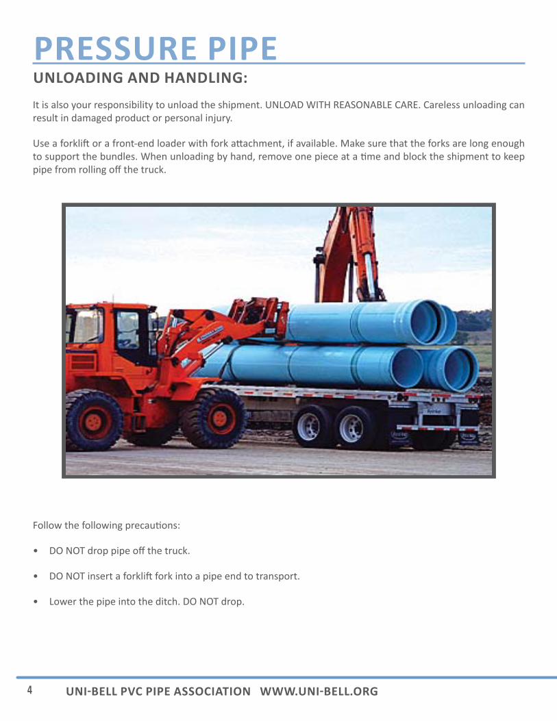
PRESSURE PIPEUNLOADING AND HANDLING:It is also your responsibility to unload the shipment. UNLOAD WITH REASONABLE CARE. Careless unloading can result in damaged product or personal injury.
Use a forkli or a front-end loader with fork a achment, if available. Make sure that the forks are long enough to support the bundles. When unloading by hand, remove one piece at a me and block the shipment to keep pipe from rolling off the truck.
Follow the following precau ons:
• DO NOT drop pipe off the truck.
• DO NOT insert a forkli fork into a pipe end to transport.
• Lower the pipe into the ditch. DO NOT drop.
5INSTALLATION GUIDE FOR PVC PRESSURE PIPE
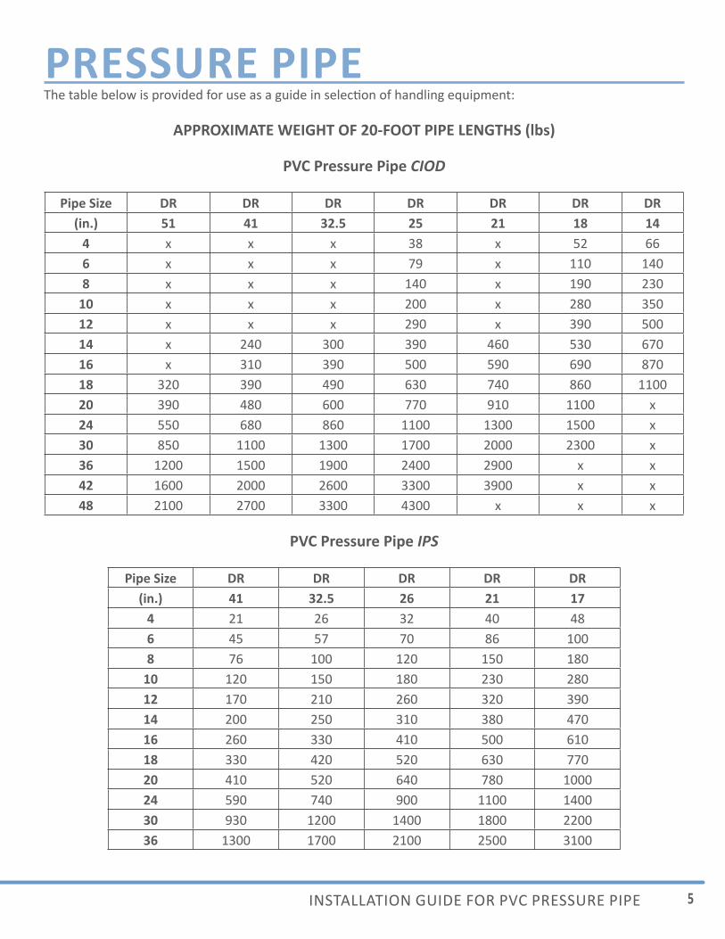
PRESSURE PIPEThe table below is provided for use as a guide in selec on of handling equipment:
APPROXIMATE WEIGHT OF 20-FOOT PIPE LENGTHS (lbs)
PVC Pressure Pipe CIOD
Pipe Size DR DR DR DR DR DR DR(in.) 51 41 32.5 25 21 18 14
4 x x x 38 x 52 666 x x x 79 x 110 1408 x x x 140 x 190 230
10 x x x 200 x 280 35012 x x x 290 x 390 50014 x 240 300 390 460 530 67016 x 310 390 500 590 690 87018 320 390 490 630 740 860 110020 390 480 600 770 910 1100 x24 550 680 860 1100 1300 1500 x30 850 1100 1300 1700 2000 2300 x36 1200 1500 1900 2400 2900 x x42 1600 2000 2600 3300 3900 x x48 2100 2700 3300 4300 x x x
PVC Pressure Pipe IPS
Pipe Size DR DR DR DR DR(in.) 41 32.5 26 21 17
4 21 26 32 40 486 45 57 70 86 1008 76 100 120 150 180
10 120 150 180 230 28012 170 210 260 320 39014 200 250 310 380 47016 260 330 410 500 61018 330 420 520 630 77020 410 520 640 780 100024 590 740 900 1100 140030 930 1200 1400 1800 220036 1300 1700 2100 2500 3100
6 UNI BELL PVC PIPE ASSOCIATION WWW.UNI BELL.ORG
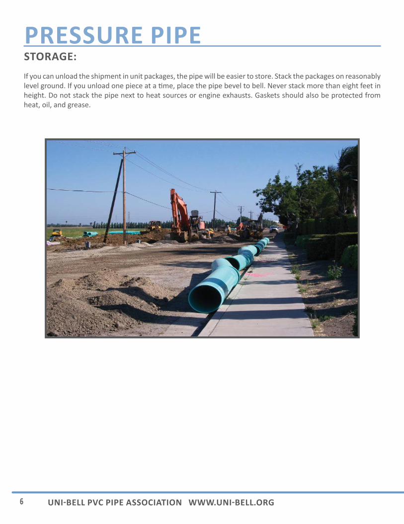
PRESSURE PIPESTORAGE:If you can unload the shipment in unit packages, the pipe will be easier to store. Stack the packages on reasonably level ground. If you unload one piece at a me, place the pipe bevel to bell. Never stack more than eight feet in height. Do not stack the pipe next to heat sources or engine exhausts. Gaskets should also be protected from heat, oil, and grease.
7INSTALLATION GUIDE FOR PVC PRESSURE PIPE
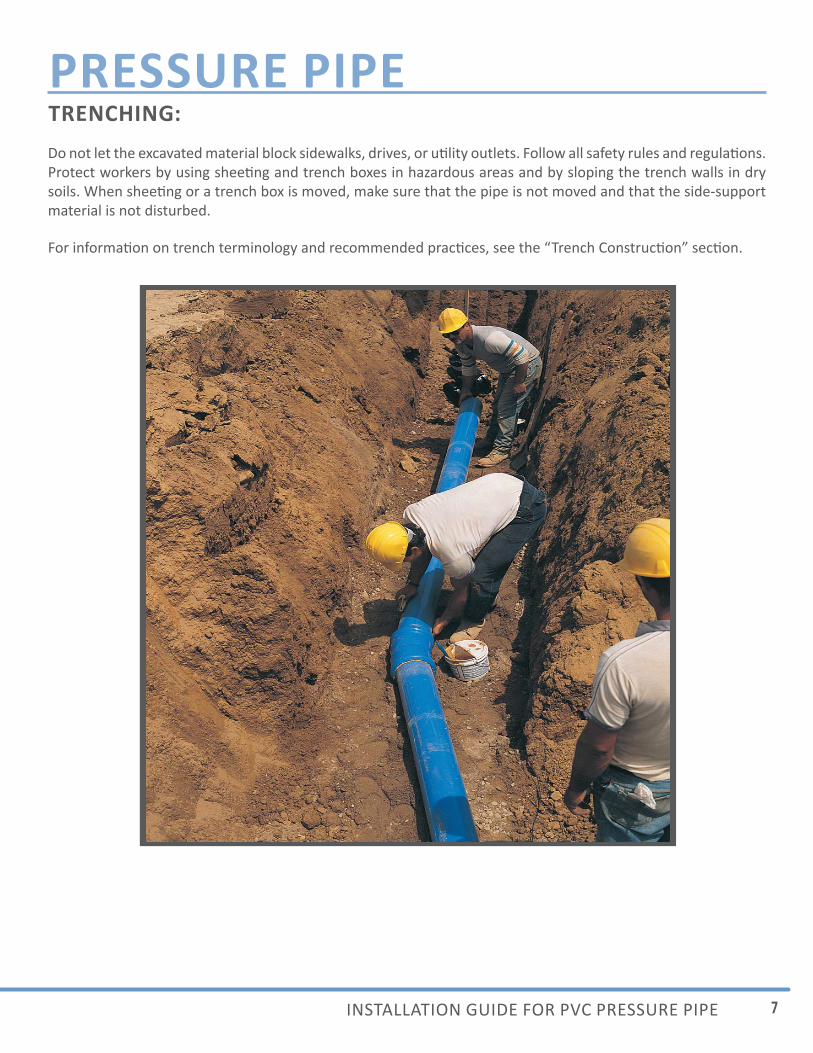
PRESSURE PIPETRENCHING:Do not let the excavated material block sidewalks, drives, or u lity outlets. Follow all safety rules and regula ons. Protect workers by using shee ng and trench boxes in hazardous areas and by sloping the trench walls in dry soils. When shee ng or a trench box is moved, make sure that the pipe is not moved and that the side-support material is not disturbed.
For informa on on trench terminology and recommended prac ces, see the “Trench Construc on” sec on.
8 UNI BELL PVC PIPE ASSOCIATION WWW.UNI BELL.ORG
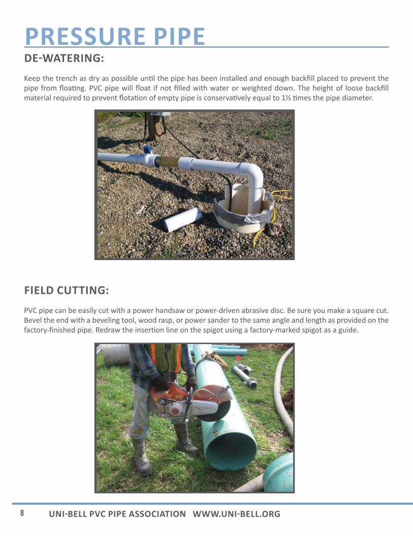
PRESSURE PIPEDE WATERING:Keep the trench as dry as possible un l the pipe has been installed and enough backfi ll placed to prevent the pipe from fl oa ng. PVC pipe will fl oat if not fi lled with water or weighted down. The height of loose backfi ll material required to prevent fl ota on of empty pipe is conserva vely equal to 1½ mes the pipe diameter.
FIELD CUTTING:PVC pipe can be easily cut with a power handsaw or power-driven abrasive disc. Be sure you make a square cut. Bevel the end with a beveling tool, wood rasp, or power sander to the same angle and length as provided on the factory-fi nished pipe. Redraw the inser on line on the spigot using a factory-marked spigot as a guide.
9INSTALLATION GUIDE FOR PVC PRESSURE PIPE
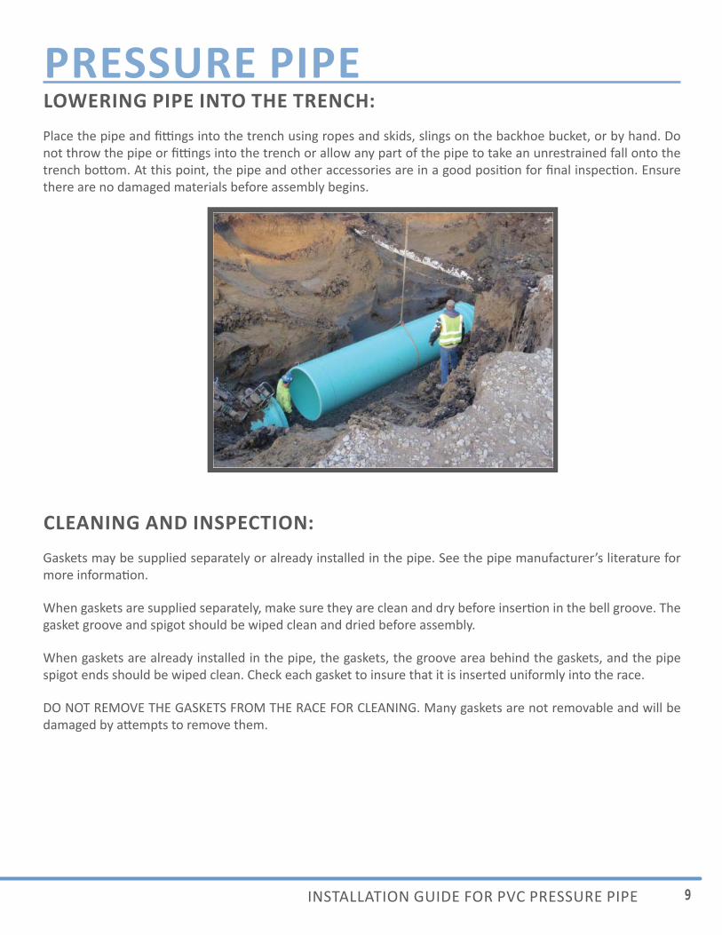
PRESSURE PIPELOWERING PIPE INTO THE TRENCH:Place the pipe and fi ngs into the trench using ropes and skids, slings on the backhoe bucket, or by hand. Do not throw the pipe or fi ngs into the trench or allow any part of the pipe to take an unrestrained fall onto the trench bo om. At this point, the pipe and other accessories are in a good posi on for fi nal inspec on. Ensure there are no damaged materials before assembly begins.
CLEANING AND INSPECTION:Gaskets may be supplied separately or already installed in the pipe. See the pipe manufacturer’s literature for more informa on.
When gaskets are supplied separately, make sure they are clean and dry before inser on in the bell groove. The gasket groove and spigot should be wiped clean and dried before assembly.
When gaskets are already installed in the pipe, the gaskets, the groove area behind the gaskets, and the pipe spigot ends should be wiped clean. Check each gasket to insure that it is inserted uniformly into the race.
DO NOT REMOVE THE GASKETS FROM THE RACE FOR CLEANING. Many gaskets are not removable and will be damaged by a empts to remove them.
10 UNI BELL PVC PIPE ASSOCIATION WWW.UNI BELL.ORG
PRESSURE PIPELUBRICATION:Lubricant should be applied to the bevel of the spigot end and approximately mid-way back to the inser on line. Some manufacturers recommend applying lubricant to the gasket surface which makes contact with the spigot end. Use only the lubricants supplied or recommended by the pipe manufacturer.
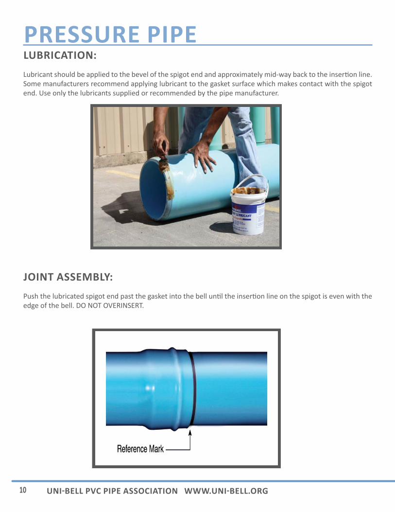
JOINT ASSEMBLY:Push the lubricated spigot end past the gasket into the bell un l the inser on line on the spigot is even with the edge of the bell. DO NOT OVERINSERT.
11INSTALLATION GUIDE FOR PVC PRESSURE PIPE
PRESSURE PIPEIf you have trouble with assembly, disassemble the joint and examine the gasket. If the gasket is removable, replace if damaged. If non-removable gaskets are damaged, cut off the bell, bevel the new edge, and use a coupling to assemble. Be sure that the gasket is properly seated and that both pipe lengths are in straight alignment. Repeat assembly steps as stated on previous page. Correct assembly is achieved when the inser on line on the spigot is lined up with the edge of the bell. If mul ple inser on lines exist, insert un l only one line is visible.
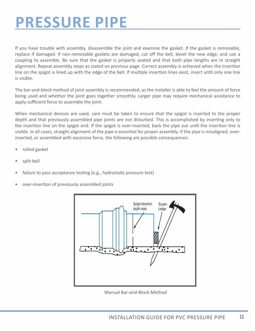
The bar-and-block method of joint assembly is recommended, as the installer is able to feel the amount of force being used and whether the joint goes together smoothly. Larger pipe may require mechanical assistance to apply suffi cient force to assemble the joint.
When mechanical devices are used, care must be taken to ensure that the spigot is inserted to the proper depth and that previously assembled pipe joints are not disturbed. This is accomplished by inser ng only to the inser on line on the spigot end. If the spigot is over-inserted, back the pipe out un l the inser on line is visible. In all cases, straight alignment of the pipe is essen al for proper assembly. If the pipe is misaligned, over-inserted, or assembled with excessive force, the following are possible consequences:
• rolled gasket
• split bell
• failure to pass acceptance tes ng (e.g., hydrosta c pressure test)
• over-inser on of previously assembled joints
Manual Bar-and-Block Method
12 UNI BELL PVC PIPE ASSOCIATION WWW.UNI BELL.ORG
PRESSURE PIPEINSTALLING PIPE THROUGH CASINGS:When the pipeline intercepts a heavily traveled, protected, or landscaped area it may be necessary to install the pipe through a casing. There are four precau ons to observe while pushing the pipe through the casing:
1. Install spacers on the PVC pipe.
2. Minimize the fric on force during the push.
3. Avoid over-inser on.
4. Install a water-permeable seal at the casing ends.
Casing size: The casing should be large enough to readily accommodate the maximum outside diameter at the pipe bells and the projec ons of the suppor ng spacers. The casing should not be so large as to permit excessive “whipping” or “snaking” of the PVC pipe when it is pressurized.
Casing spacers: Casing spacers are available to provide proper separa on between the casing and the PVC pipe to be installed. Spacers come complete with runners to provide clearance for the bell-and-spigot assemblies. The casing-spacer manufacturer should be contacted for informa on on the loca on and number of spacers required.
INSTALLATION OF FITTINGS AND VALVES:The inser on depths of valve and fi ng joints are usually less than those of PVC pipe joints. For proper inser on depth of PVC fi ngs, check with the manufacturers of the fi ngs. For iron fi ngs, cut the spigot end to remove the factory bevel. Make sure the pipe spigot end is squarely cut, deburred, and the sharp edge removed. Insert the pipe spigot into the iron fi ng bell un l the pipe end contacts the fi ng. See AWWA Standard C605 “Standard for the Underground Installa on of PVC and PVCO Pressure Pipe and Fi ngs.”
Joint Restraint Devices: Mechanical thrust-restraint devices are available which clamp to the wall of the pipe and e back to a ma ng collar on the fi ng or pipe bell. Integral self-restraining bell and spigot joints are also available. Contact the joint restraint manufacturer for installa on recommenda ons.
TRACER WIRE:Properly installed tracer wire will aid in loca ng PVC pipe. Typically, an insulated wire or plas c-coated metal strip is laid above the pipe a er installa on. The tracer wire is generally accessible at a riser, but is not electrically connected to the riser.
13INSTALLATION GUIDE FOR PVC PRESSURE PIPE
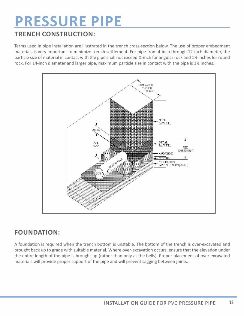
PRESSURE PIPETRENCH CONSTRUCTION:Terms used in pipe installa on are illustrated in the trench cross-sec on below. The use of proper embedment materials is very important to minimize trench se lement. For pipe from 4-inch through 12-inch diameter, the par cle size of material in contact with the pipe shall not exceed ¾-inch for angular rock and 1½ inches for round rock. For 14-inch diameter and larger pipe, maximum par cle size in contact with the pipe is 1½ inches.
FOUNDATION:A founda on is required when the trench bo om is unstable. The bo om of the trench is over-excavated and brought back up to grade with suitable material. Where over-excava on occurs, ensure that the eleva on under the en re length of the pipe is brought up (rather than only at the bells). Proper placement of over-excavated materials will provide proper support of the pipe and will prevent sagging between joints.
14 UNI BELL PVC PIPE ASSOCIATION WWW.UNI BELL.ORG
PRESSURE PIPEBEDDING:Bedding may be used to bring the trench bo om up to grade before the pipe is installed. The purpose of bedding is to provide con nuous support under the pipe. Where required (such as when rock is encountered), a minimum depth of 4 to 6 inches is typical.
Holes for pipe bells should be provided at each joint to ensure uniform support for the pipe. Bell holes should be no larger than necessary for pipe assembly.
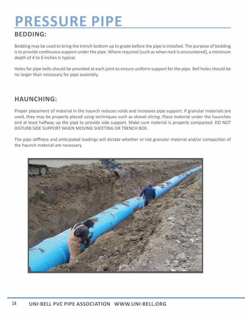
HAUNCHING:Proper placement of material in the haunch reduces voids and increases pipe support. If granular materials are used, they may be properly placed using techniques such as shovel slicing. Place material under the haunches and at least halfway up the pipe to provide side support. Make sure material is properly compacted. DO NOT DISTURB SIDE SUPPORT WHEN MOVING SHEETING OR TRENCH BOX.
The pipe s ff ness and an cipated loadings will dictate whether or not granular material and/or compac on of the haunch material are necessary.

15INSTALLATION GUIDE FOR PVC PRESSURE PIPE
PRESSURE PIPEINITIAL BACKFILL:The material placed over the crown of the pipe to a height of 6 to 12 inches is the ini al backfi ll. The purpose of the ini al backfi ll is to protect the pipe from the fi nal backfi ll. Where not otherwise specifi ed, the ini al backfi ll may consist of the na ve material in the trench provided it is not frozen and is free from large stones, debris, and other organic materials.
Machine compac on of ini al backfi ll directly over the pipe is not desirable unless adequate cover has been provided to protect the pipe. The required depth of cover will depend on the type of compac on equipment – consult the project engineer for informa on.
FINAL BACKFILL:Final backfi ll is o en specifi ed by the project engineer based on site design. Material selec on, placement, and compac on should meet the project requirements. In many cases, the material that was originally excavated can be used for fi nal backfi ll.
16 UNI BELL PVC PIPE ASSOCIATION WWW.UNI BELL.ORG
PRESSURE PIPECOMPACTING THE BACKFILL: Compact the haunching, ini al backfi ll, and fi nal backfi ll in accordance with the job drawings. Observe the following precau ons:
• When a “self-compac ng” material is used (such as crushed stone), ensure that the material does not arch or bridge beneath the haunch of the pipe. Remove such voids by shovel slicing.
• When compac ng the material underneath and at either side of the pipe, do not allow the tool or the machine to strike the pipe.
It is not necessary to compact the ini al backfi ll directly over the top of the pipe for the sake of the pipe’s structural strength. However, it may be necessary for roadway integrity and for minimizing trench se lement.
OVERNIGHT PRECAUTIONS:At the end of each workday, be sure that all installed pipe ends are covered to keep dirt, debris, and animals from entering the pipe. Backfi ll as needed to avoid fl ota on.
ACCEPTANCE TESTING:General: When local condi ons require that trenches be backfi lled immediately a er pipe has been laid, tes ng may be carried out a er backfi lling has been completed. In all cases, suffi cient backfi ll (minimum depth 1½ mes the pipe size) shall be placed to confi ne the pipe system during tes ng.
The engineer shall assure that the test pressure does not exceed the design pressure of any of the components of the pipe system.
Procedure: Tes ng shall be performed only a er the pipeline has been properly fi lled, fl ushed, and purged of all air. The specifi ed test pressure shall be applied by means of an approved pumping assembly connected to the pipe in a manner sa sfactory to the purchaser. To prevent pipe movement, the contractor shall have placed suffi cient backfi ll prior to fi lling and tes ng of the pipe. The test pressure shall not exceed the test pressure specifi ed by the engineer. If necessary, the test pressure shall be maintained by addi onal pumping for the specifi ed me during which the system and all exposed pipe, fi ngs, valves, and hydrants shall be carefully examined for leakage. All visible leaks shall be stopped. All defec ve elements shall be repaired or removed and replaced. The test shall be repeated un l the test requirements have been met.
Test Dura on: The dura on of the hydrosta c test shall be 2 hours, unless otherwise specifi ed.
17INSTALLATION GUIDE FOR PVC PRESSURE PIPE
PRESSURE PIPETest Pressure: The hydrosta c test pressure shall not be less than 125% of the maximum an cipated sustained working pressure at the highest point along the test sec on unless the pressure exceeds the design pressure limit for any component of the test sec on. In no case shall the test pressure exceed the design pressure limit for any component, including pipe, valve, fi ng, thrust restraint, or other appurtenance.
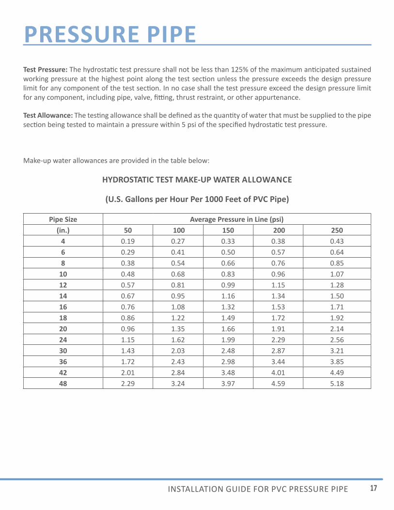
Test Allowance: The tes ng allowance shall be defi ned as the quan ty of water that must be supplied to the pipe sec on being tested to maintain a pressure within 5 psi of the specifi ed hydrosta c test pressure.
Make-up water allowances are provided in the table below:
HYDROSTATIC TEST MAKE-UP WATER ALLOWANCE
(U.S. Gallons per Hour Per 1000 Feet of PVC Pipe)
Pipe Size Average Pressure in Line (psi)(in.) 50 100 150 200 250
4 0.19 0.27 0.33 0.38 0.436 0.29 0.41 0.50 0.57 0.648 0.38 0.54 0.66 0.76 0.85
10 0.48 0.68 0.83 0.96 1.0712 0.57 0.81 0.99 1.15 1.2814 0.67 0.95 1.16 1.34 1.5016 0.76 1.08 1.32 1.53 1.7118 0.86 1.22 1.49 1.72 1.9220 0.96 1.35 1.66 1.91 2.1424 1.15 1.62 1.99 2.29 2.5630 1.43 2.03 2.48 2.87 3.2136 1.72 2.43 2.98 3.44 3.8542 2.01 2.84 3.48 4.01 4.4948 2.29 3.24 3.97 4.59 5.18
18 UNI BELL PVC PIPE ASSOCIATION WWW.UNI BELL.ORG
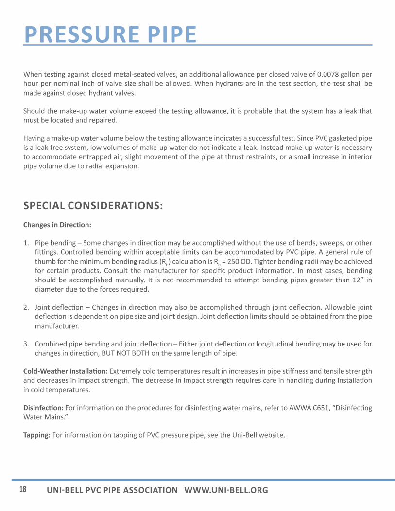
PRESSURE PIPEWhen tes ng against closed metal-seated valves, an addi onal allowance per closed valve of 0.0078 gallon per hour per nominal inch of valve size shall be allowed. When hydrants are in the test sec on, the test shall be made against closed hydrant valves.
Should the make-up water volume exceed the tes ng allowance, it is probable that the system has a leak that must be located and repaired.
Having a make-up water volume below the tes ng allowance indicates a successful test. Since PVC gasketed pipe is a leak-free system, low volumes of make-up water do not indicate a leak. Instead make-up water is necessary to accommodate entrapped air, slight movement of the pipe at thrust restraints, or a small increase in interior pipe volume due to radial expansion.
SPECIAL CONSIDERATIONS:Changes in Direc on:
1. Pipe bending – Some changes in direc on may be accomplished without the use of bends, sweeps, or other fi ngs. Controlled bending within acceptable limits can be accommodated by PVC pipe. A general rule of thumb for the minimum bending radius (Rb) calcula on is Rb = 250 OD. Tighter bending radii may be achieved for certain products. Consult the manufacturer for specifi c product informa on. In most cases, bending should be accomplished manually. It is not recommended to a empt bending pipes greater than 12” in diameter due to the forces required.
2. Joint defl ec on – Changes in direc on may also be accomplished through joint defl ec on. Allowable joint defl ec on is dependent on pipe size and joint design. Joint defl ec on limits should be obtained from the pipe manufacturer.
3. Combined pipe bending and joint defl ec on – Either joint defl ec on or longitudinal bending may be used for changes in direc on, BUT NOT BOTH on the same length of pipe.
Cold-Weather Installa on: Extremely cold temperatures result in increases in pipe s ff ness and tensile strength and decreases in impact strength. The decrease in impact strength requires care in handling during installa on in cold temperatures.
Disinfec on: For informa on on the procedures for disinfec ng water mains, refer to AWWA C651, “Disinfec ng Water Mains.”
Tapping: For informa on on tapping of PVC pressure pipe, see the Uni-Bell website.
19INSTALLATION GUIDE FOR PVC PRESSURE PIPE
PRESSURE PIPECHECKLIST:• Take all precau ons necessary to protect workers and materials.
• Plan ahead for fi ngs.
• Use trench boxes or shoring as required.
• Do not disturb installed pipe when moving trench boxes or shoring materials.
• Properly assemble pipe joints by inser ng the spigot end un l the inser on line is even with the bell lip.
• Keep the trench bo om as dry as possible.
• For detailed installa on recommenda ons, see AWWA C605 “Standard for Underground Installa on of PVC and PVCO Pressure Pipe and Fi ngs.”
• Consult the pipe manufacturer for specifi cs regarding gaskets and lubricants.
• Check with the project engineer regarding specifi ca ons and procedures.
20 UNI BELL PVC PIPE ASSOCIATION WWW.UNI BELL.ORG
PRESSURE PIPEUNI BELL LITERATURE:
Recommended Standards
UNI-B-1 “Recommended Specifi ca ons for Thermoplas c Pipe Joints, Pressure and Non-Pressure Applica ons”
UNI-B-8 “Recommended Prac ce for the Direct Tapping of Polyvinyl Chloride (PVC) Pressure Water Pipe (Nominal Diameters 6-12 Inches)”
UNI-B-15 “Recommended Standard Specifi ca on for Polyvinyl Chloride (PVC) Fabricated Pressure Fi ngs”
Technical Reports
UNI-TR-1 “Defl ec on: The Pipe/Soil Mechanism”
UNI-TR-5 “The Eff ects of Ultraviolet Radia on on PVC Pipe”
UNI-TR-6 “PVC Force Main Design”
UNI-TR-7 “Thermoplas c Pressure Pipe Design”
21INSTALLATION GUIDE FOR PVC PRESSURE PIPE
PRESSURE PIPEMEMBERS:CERTAINTEED
DIAMOND PLASTICS CORPORATION
IPEX USA LLC
JM EAGLE
NATIONAL PIPE & PLASTICS, INC.
NORTH AMERICAN PIPE CORPORATION
PIPELIFE JET STREAM, INC.
ROYAL BUILDING PRODUCTS
SANDERSON PIPE
The statements contained in this recommended installa on guide are those of the Uni-Bell PVC Pipe Associa- on and are not warran es, nor are they intended to be warran es. Inquiries for informa on on specifi c prod-
ucts, their a ributes and recommended uses, and the manufacturer’s warranty should be directed to member companies.
UNI-PUB-9-12
UNI BELL PVC PIPE ASSOCIATION 2711 LBJ Freeway, Suite 1000
Dallas, TX 75234(972) 243-3902
WWW.UNI BELL.ORG