gasification of unconventional feedstocks || feedstocks
TRANSCRIPT

CHAPTER 11Feedstocks
1 INTRODUCTION
Gasification is a process that converts organic carbonaceous feedstocksinto carbon monoxide, carbon dioxide, and hydrogen by reacting thefeedstock at high temperatures (. 700�C, 1290�F), without combus-tion, with a controlled amount of oxygen and/or steam (Lee et al.,2007; Speight, 2008, 2013a, 2013b). The resulting gas mixture (synthe-sis gas) is called a producer gas and is itself a fuel. The power derivedfrom carbonaceous feedstocks and gasification followed by the com-bustion of the product gas(es) is considered to be a source of renewableenergy if the gaseous products are from a source (e.g., biomass) otherthan a fossil fuel (Speight, 2008).
For many decades coal has been the primary feedstock for gasifica-tion units but recent concerns about the use of fossil fuels and theresulting environmental pollutants, irrespective of the various gascleaning processes and gasification plant environmental cleanupefforts, there is a move to feedstocks other than coal for gasificationprocesses (Speight, 2013a, 2013b). But more pertinent to the presenttext, the gasification process can also use carbonaceous feedstockswhich would otherwise have been discarded and unused, such as wastebiomass and other similar biodegradable wastes. Various feedstockssuch as biomass, petroleum resids, and other carbonaceous wastes canbe used to their fullest potential. In fact, the refining industry has seenfit to use residua gasification as a source of hydrogen for the past sev-eral decades (Speight, 2014).
The advantage of the gasification process when a carbonaceousfeedstock (a feedstock containing carbon) or hydrocarbonaceous feed-stock (a feedstock containing carbon and hydrogen) is employed isthat the product of focus � synthesis gas � is potentially more usefulas an energy source and results in an overall cleaner process. The pro-duction of synthesis gas is a more efficient production of an energysource than, say, the direct combustion of the original feedstockbecause synthesis gas can be (1) combusted at higher temperatures,

(2) used in fuel cells, (3) used to produce methanol, (4) used as a sourceof hydrogen, and particularly (5) converted via the Fischer2Tropschprocess into a range of synthesis liquid fuels suitable for use in gasolineengines or diesel engines (Chapters 4, and 5).
Gasification plants are cleaner because fewer sulfur and nitrogenbyproducts are produced thereby contributing to a decrease in smog for-mation and acid rain deposition. For this reason, gasification is anappealing process for the utilization of relatively inexpensive feedstocksthat might otherwise be declared as waste and sent to a landfill (wherethe production of methane � a so-called greenhouse gas � will be pro-duced) or combusted which may not (depending upon the feedstock) beenergy efficient. Overall, use of a gasification technology (Chapter 3)with the necessary gas cleanup options can have a smaller environmen-tal footprint and lesser effect on the environment than landfill opera-tions or combustion of the waste. Indeed, the increasing interest ingasification technology reflects a convergence of two changes in theelectricity generation marketplace: (1) the maturity of gasification tech-nology, and (2) the extremely low emissions from integrated gasificationcombined cycle (IGCC) plants, especially air emissions, and the poten-tial for lower cost control of greenhouse gases than other coal-based sys-tems (Speight, 2013b).
Liquid fuels, including gasoline, diesel, naphtha and jet fuel, areusually processed by refining crude oil (Speight, 2014). Due to thedirect distillation, crude oil is the raw material most suited to liquidfuel production. However, with the fluctuating and rising cost of pro-cessing petroleum, coal-to-liquids (CTL) and biomass-to-liquids(BTL) processes are employed as alternative routes for liquid fuelproduction. Both of these feedstocks are converted to synthesis gas �a mixture of carbon monoxide and hydrogen � after which the tried-and-tested Fischer2Tropsch (FT) technology is used to convert thesynthesis gas to a mixture of liquid products, which is furtherupgraded using known petroleum refinery technologies to producegasoline, naphtha, diesel fuel, and jet fuel (Dry, 1976; Mukoma et al.,2006; Chadeesingh, 2011; Speight, 2014).
This chapter presents a description of the various non-coal feed-stocks that can be used in gasification to produce a variety of gases,including synthesis gas (a mixture of carbon monoxide andhydrogen).
2 Gasification of Unconventional Feedstocks
2 FEEDSTOCKS
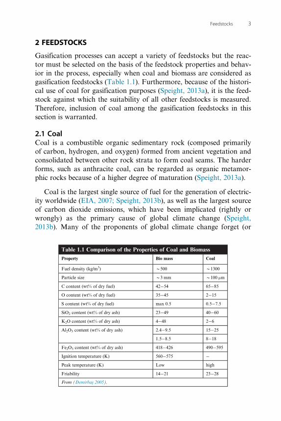
Gasification processes can accept a variety of feedstocks but the reac-tor must be selected on the basis of the feedstock properties and behav-ior in the process, especially when coal and biomass are considered asgasification feedstocks (Table 1.1). Furthermore, because of the histori-cal use of coal for gasification purposes (Speight, 2013a), it is the feed-stock against which the suitability of all other feedstocks is measured.Therefore, inclusion of coal among the gasification feedstocks in thissection is warranted.
2.1 CoalCoal is a combustible organic sedimentary rock (composed primarilyof carbon, hydrogen, and oxygen) formed from ancient vegetation andconsolidated between other rock strata to form coal seams. The harderforms, such as anthracite coal, can be regarded as organic metamor-phic rocks because of a higher degree of maturation (Speight, 2013a).
Coal is the largest single source of fuel for the generation of electric-ity worldwide (EIA, 2007; Speight, 2013b), as well as the largest sourceof carbon dioxide emissions, which have been implicated (rightly orwrongly) as the primary cause of global climate change (Speight,2013b). Many of the proponents of global climate change forget (or
Table 1.1 Comparison of the Properties of Coal and BiomassProperty Bio mass Coal
Fuel density (kg/m3) B500 B1300
Particle size B3 mm B100 µm
C content (wt% of dry fuel) 42�54 65�85
O content (wt% of dry fuel) 35�45 2�15
S content (wt% of dry fuel) max 0.5 0.5�7.5
SiO2 content (wt% of dry ash) 23�49 40�60
K2O content (wt% of dry ash) 4�48 2�6
Al2O3 content (wt% of dry ash) 2.4�9.5 15�25
1.5�8.5 8�18
Fe2O3 content (wt% of dry ash) 418�426 490�595
Ignition temperature (K) 560�575 �Peak temperature (K) Low high
Friability 14�21 23�28
From (Demirbas 2005).
3Feedstocks

refuse to acknowledge) that the earth is in an interglacial period whenwarming and climate change can be expected � this was reflected inthe commencement of the melting of the glaciers approximately 11 000years ago. Thus, taking into account the geological sequence of events,the contribution of carbon dioxide from anthropogenic sources is notknown with any degree of accuracy.
Coal occurs in different forms or types (Speight, 2013a). Variationsin the nature of the source material and local or regional variations inthe coalification processes caused the vegetal matter to evolve differ-ently. Thus, various classification systems exist to define the differenttypes of coal. Thus, as geological processes increase their effect overtime, the coal precursors are transformed over time into:
(1) Lignite � also referred to as brown coal and is the lowest rank ofcoal that is used almost exclusively as fuel for steam-electric powergeneration; jet is a compact form of lignite that is sometimes polishedand has been used as an ornamental stone since the Iron Age.
(2) Sub-bituminous coal, which exhibits properties ranging from thoseof lignite to those of bituminous coal and are used primarily asfuel for steam-electric power generation.
(3) Bituminous coal, which is a dense coal, usually black, sometimesdark brown, often with well-defined bands of bright and dull mate-rial, used primarily as fuel in steam-electric power generation, withsubstantial quantities also used for heat and power applications inmanufacturing and to make coke.
(4) Anthracite, which is the highest rank coal and is a hard, glossy, blackcoal used primarily for residential and commercial space heating.
Chemically, coal is a hydrogen-deficient hydrocarbon with anatomic hydrogen-to-carbon ratio near 0.8, as compared to petroleumhydrocarbons, which have an atomic hydrogen-to-carbon ratio approx-imately equal to 2, and methane (CH4) that has an atomic carbon-to-hydrogen ratio equal to 4. For this reason, any process used to convertcoal to alternative fuels must add hydrogen or redistribute the hydro-gen in the original coal to produce hydrogen-rich products and coke(Speight, 2013a).
In the gasification of coal, a mixture of gases is produced � in addi-tion to synthesis gas (mixtures of carbon monoxide and hydrogen),methane and other hydrocarbons are also produced depending on the
4 Gasification of Unconventional Feedstocks

conditions involved. The gases are withdrawn and may be burned toproduce heat, generate electricity, or are used as synthesis gas in indi-rect liquefaction or the production of chemicals. The indirect liquefac-tion process involves Fischer2Tropsch synthesis which results in theproduction of hydrocarbons that can be refined into liquid fuels.
By developing adsorbents to capture the pollutants (mercury, sulfur,arsenic, and other harmful gases), there is a focus not only on thereduction of the quantity of gaseous emissions but also on maximiza-tion of the thermal efficiency of the cleanup methods. Thus, gasifica-tion offers one of the most clean and versatile ways to convert theenergy contained in coal into electricity, hydrogen, and other sourcesof power.
However, coal is an abundant natural resource but the combustionor gasification of coal produces both toxic pollutants and greenhousegases. By developing adsorbents to capture the pollutants (mercury,sulfur, arsenic, and other harmful gases), there have been seriousefforts to reduce the quantity of emitted gases and also to maximizethe thermal efficiency of the cleanup. Thus, gasification can offer oneof the most clean and versatile ways to convert the energy contained incoal into electricity, hydrogen, and other sources of power.
2.2 Petroleum CokeCoke is the solid carbonaceous material produced from petroleum dur-ing thermal processing. More particularly, coke is the residue left bythe destructive distillation (i.e., thermal cracking such as the delayedcoking process) of petroleum residua. The coke formed in catalyticcracking operations is usually non-recoverable because of the materialsdeposited on the catalyst during the process and such coke is oftenemployed as fuel for the process (Speight, 2014). It is often character-ized as a solid material with a honeycomb-type of appearance havinghigh carbon content (95%1 w/w) with some hydrogen and, dependingon the process, sulfur and nitrogen as well. The color varies from grayto black, and the material is insoluble in organic solvents.
Typically, the composition of petroleum coke varies with the sourceof the crude oil, but in general, large amounts of high-molecular-weight complex hydrocarbons (rich in carbon but correspondinglypoor in hydrogen) make up a high proportion. The solubility of
5Feedstocks

petroleum coke in carbon disulfide has been reported to be as high as50 to 80%, but this is in fact a misnomer and is due to soluble productadsorbed on the coke � by definition coke is the insoluble, honeycombmaterial that is the end product of thermal processes. However, coke isnot always a product with little use � three physical structures of cokecan be produced by delayed coking: (1) shot coke, (2) sponge coke, or(3) needle coke, which find different uses within the industry.
Shot coke is an abnormal type of coke resembling small balls. Dueto mechanisms not well understood the coke from some coker feed-stocks forms into small, tight, non-attached clusters that look like pel-lets, marbles, or ball bearings. It usually is a very hard coke, i.e., lowHardgrove grindability index (Speight, 2013a). Such coke is less desir-able to the end users because of difficulties in handling and grinding. Itis believed that feedstocks high in asphaltene constituents and low APIfavor shot coke formation. Blending aromatic materials with the feed-stock and/or increasing the recycle ratio reduces the yield of shot coke.Fluidization in the coke drums may cause formation of shot coke.Occasionally, the smaller shot coke may agglomerate into ostrich eggsized pieces. Such coke may be more suitable as a gasificationfeedstock.
Sponge coke is the common type of coke produced by delayed cok-ing units. It is in a form that resembles a sponge and has been calledhoneycombed. Sponge coke, mostly used for anode-grade carbon, isdull and black, having porous, amorphous structure.
Needle coke (acicular coke), a special quality coke produced fromaromatic feed stocks, is silver-gray, having crystalline broken needlestructure, and is believed to be chemically produced through cross-linking of condensed aromatic hydrocarbons during coking reactions.It has a crystalline structure with more unidirectional pores and is usedin the production of electrodes for the steel and aluminum industriesand is particularly valuable because the electrodes must be replacedregularly.
Petroleum coke is employed for a number of purposes, but its chiefuse is (depending upon the degree of purity, i.e., contains a lowamount of contaminants) for the manufacture of carbon electrodesfor aluminum refining, which requires a high-purity carbon 2 low inash and sulfur free; the volatile matter must be removed by calcining.
6 Gasification of Unconventional Feedstocks

In addition to its use as a metallurgical reducing agent, petroleum cokeis employed in the manufacture of carbon brushes, silicon carbideabrasives, and structural carbon (e.g., pipes and Raschig rings), as wellas calcium carbide manufacture from which acetylene is produced:
Coke-CaC2
CaC21H2O-HC � CH(1.1.1)
Considering the properties of coke and the potential non-use of thehighly contaminated material, gasification is the only technology whichmakes possible for the refineries the zero residue target, contrary to allconversion technologies, thermal cracking, catalytic cracking, cooking,deasphalting, hydroprocessing, etc., which can only reduce the bottomvolume, with the complication that the residue qualities generally getworse with the degree of conversion (Speight, 2014).
Indeed, the flexibility of the gasification technology permits therefinery to handle any kind of refinery residue, including petroleumcoke, tank bottoms, and refinery sludge and makes available a rangeof value added products, electricity, steam, hydrogen and various che-micals based on synthesis gas chemistry: methanol, ammonia, MTBE,TAME, acetic acid, and formaldehyde (Speight, 2008, 2013a). Withrespect to gasification, no other technology processing low value refin-ery residues can come close to the emission levels achievable with gasi-fication (Speight, 2014) and is projected to be a major part of therefinery of the future (Speight, 2011b).
Gasification is also a method for converting petroleum coke and otherrefinery non-volatile waste streams (often referred to as refinery residualsand include but not limited to atmospheric residuum, vacuum residuum,visbreaker tar, and deasphalter pitch) into power, steam, and hydrogenfor use in the production of cleaner transportation fuels. For the gasifica-tion of coal and biomass, the main requirement for a feedstock to a gasifi-cation unit is that it contains both hydrogen and carbon (Table 1.2).
The typical gasification system incorporated into the refinery con-sists of several process plants including (1) feed preparation, (2) thegasifier, (3) an air separation unit (ASU), (4) synthesis gas cleanup,(5) sulfur recovery unit (SRU), and (6) downstream process optionssuch as Fischer2Tropsch synthesis (FTS) and methanol synthesis(MTS), depending on the desired product state (Figure 1.1).
7Feedstocks

The benefits to a refinery for adding a gasification system for petro-leum coke or other residuals are: (1) production of power, steam, oxy-gen, and nitrogen for refinery use or sale, (2) source of synthesis gas forhydrogen to be used in refinery operations and for the production oflight refinery products through Fischer2Tropsch synthesis, (3) increasedefficiency of power generation, improved air emissions, and reducedwaste stream versus combustion of petroleum coke or residua or in-cineration, (4) no off-site transportation or storage for petroleum cokeor residuals, and (5) the potential to dispose of waste streams includinghazardous materials.
Gasification of coke can provide high-purity hydrogen for a varietyof uses within the refinery such as (1) sulfur removal, (2) nitrogenremoval, as well as removal of other impurities from intermediate tofinished product streams and in hydrocracking operations for the con-version of heavy distillates and oils into light products, naphtha, kero-sene, and diesel fuel (Speight, 2014). Hydrocracking and severehydrotreating require hydrogen which is at least 99% v/v pure,
Table 1.2 Types of Refinery Feedstocks Available for Gasification on-siteUnits Vacuum Residuum Visbreaker Tar Asphalt Petcoke
Ultimate analysis
C wt/wt 84.9% 86.1% 85.1% 88.6%
H " 10.4% 10.4% 9.1% 2.8%
Na " 0.5% 0.6% 0.7% 1.1%
Sa " 4.2% 2.4% 5.1% 7.3%
O " 0.5% 0.0%
Ash " 0.0% 0.1% 0.2%
Total wt/wt 100.0% 100.0% 100.0% 100.0%
H2/C ratio mol/mol 0.727 0.720 0.640 0.188
Density
Specific gravity 60a/60a 1.028 1.008 1.070 0.863
API gravity APIa 6.2 8.88 0.8 �Heating values
Higher heating value (dry) M Btu/lb 17.72 18.6 17.28 14.85
Lower heating value (dry) " 16.77 17.6 16.45 14.48aNitrogen and Sulfur contents vary widely.Source: National Energy Technology Laboratory, United States Department of Energy, Washington, DC.http://www.netl.doe.gov/technologies/coalpower/gasification/gasifipedia/7-advantages/7-3-4_refinery.html.
8 Gasification of Unconventional Feedstocks

while less severe hydrotreating requires a gas stream containing hydro-gen on the order of 90% v/v purity.
Electric power and high pressure steam can be generated by the gas-ification of petroleum coke and residuals to drive mostly small andintermittent loads such as compressors, blowers, and pumps. Steamcan also be used for process heating, steam tracing, partial pressurereduction in fractionation systems, and stripping low-boiling compo-nents to stabilize process streams.
During gasification some soot (typically 99%1 carbon) is produced,which ends up in the quench water. The soot is transferred to the feed-stock by contacting, in sequence, the quench water blowdown withnaphtha, and then the naphtha2 soot slurry with a fraction of thefeed. The soot mixed with the feed is recycled to the gasifier, thusachieving 100% conversion of carbon to gas.
2.3 Petroleum ResiduaA petroleum resid (residuum, pl. residua, resids) is the residue obtainedfrom petroleum after non-destructive distillation of the petroleum feed-stock has removed all of the volatile materials. The temperature of thedistillation is usually maintained below 350�C (660�F) since the rate ofthermal decomposition of petroleum constituents is minimal below this
Refineryresiduals Feed
prep
AirASU
SRU
H2S, NH3, etc.
Oxygen
Gasifier
Slag
Sulfur
Syngasclean-up
FTS
Co-Gen
Steam
Power
Hydrogen
FT fuels
Methanol
H2plant
MTS
Nitrogen
Figure 1.1 Gasification as might be employed on-site in a refinery. Source: National Energy TechnologyLaboratory, United States Department of Energy, Washington, DC. http://www.netl.doe.gov/technologies/coalpower/gasification/gasifipedia/7-advantages/7-3-4_refinery.html
9Feedstocks

temperature but the rate of thermal decomposition of petroleum con-stituents is substantial above 350�C (660�F) (Speight, 2014).
Resids are black, viscous materials and are obtained by distillation ofa crude oil under atmospheric pressure (atmospheric residuum) or underreduced pressure (vacuum residuum). They may be liquid at room tem-perature (generally atmospheric residua) or almost solid (generally vac-uum residua) depending upon the nature of the crude oil (Speight,2014). When a residuum is obtained from a crude oil and thermaldecomposition has commenced, it is more usual to refer to this productas pitch � although this term is usually applied to the non-volatile prod-uct from coal tar. The differences between the parent petroleum and the(atmospheric and vacuum) residua are due to the relative amounts ofvarious constituents present, which are removed from or remain in thenon-volatile residuum by virtue of their relative volatility.
The chemical composition of a residuum from an asphaltic crudeoil is complex. Physical methods of fractionation usually indicate highproportions of asphaltene constituents (heptane-insoluble materials)and resin constituents (simply, heptane-soluble materials but propane-insoluble materials), even in amounts up to 50% (or higher) of theresiduum. In addition, the presence of ash-forming metallic constitu-ents, including such organometallic compounds as those of vanadiumand nickel, is also a distinguishing feature of residua and the heavieroils. Furthermore, the deeper the cut into the crude oil, the greater isthe concentration of sulfur and metals in the residuum and the greaterthe deterioration in physical properties (Speight, 2014).
2.4 Asphalt, Tar, and PitchAsphalt does not occur naturally but is manufactured from petroleumand is a black or brown material that has a consistency varying from aviscous liquid to a glassy solid (Speight, 2014). To a point, asphalt canresemble bitumen (isolated from tar sand formation), hence the ten-dency to refer to bitumen (incorrectly) as native asphalt. It is recom-mended that there be differentiation between asphalt (manufactured)and bitumen (naturally occurring) other than by use of the qualifyingterms petroleum and native since the origins of the materials may bereflected in the resulting physicochemical properties of the two types ofmaterials. It is also necessary to distinguish between the asphalt whichoriginates from petroleum by refining and the product in which the
10 Gasification of Unconventional Feedstocks

source of the asphalt is a material other than petroleum, e.g., Wurtziliteasphalt (Speight, 2014). In the absence of a qualifying word, it should beassumed that the word asphalt (with or without qualifiers such as cut-back, solvent, and blown, which indicate the process used to produce theasphalt) refers to the product manufactured from petroleum.
When the asphalt is produced simply by distillation of an asphalticcrude oil, the product can be referred to as residual asphalt or straight-run asphalt. For example, if the asphalt is prepared by solvent extractionof residua or by light hydrocarbon (propane) precipitation, or if blownor otherwise treated, the term should be modified accordingly to qualifythe product (e.g., solvent asphalt, propane asphalt, blown asphalt).
Asphalt softens when heated and is elastic under certain conditionsand has many uses. For example, the mechanical properties of asphaltare of particular significance when it is used as a binder or adhesive.The principal application of asphalt is in road surfacing, which may bedone in a variety of ways. Light oil dust layer treatments may be builtup by repetition to form a hard surface, or a granular aggregate may beadded to an asphalt coat, or earth materials from the road surface itselfmay be mixed with the asphalt. Other important applications of asphaltinclude canal and reservoir linings, dam facings, and sea works. Theasphalt so used may be a thin, sprayed membrane, covered with earthfor protection against weathering and mechanical damage, or thickersurfaces, often including riprap (crushed rock). Asphalt is also used forroofs, coatings, floor tiles, soundproofing, waterproofing, and otherbuilding-construction elements and in a number of industrial products,such as batteries. For certain applications an asphaltic emulsion is pre-pared, in which fine globules of asphalt are suspended in water.
Tar is a product of the destructive distillation of many bituminousor other organic materials and is a brown to black, oily, viscous liquidto semisolid material. However, tar is most commonly produced frombituminous coal and is generally understood to refer to the productfrom coal, although it is advisable to specify coal tar if there is the pos-sibility of ambiguity. The most important factor in determining theyield and character of the coal tar is the carbonizing temperature.Three general temperature ranges are recognized, and the productshave acquired the designations: low-temperature tar (approximately450 to 700�C; 540 to 1290�F); mid-temperature tar (approximately 700to 900�C; 1290 to 1650�F); and high-temperature tar (approximately
11Feedstocks
900 to 1200�C; 1650 to 2190�F). Tar released during the early stagesof the decomposition of the organic material is called primary tar sinceit represents a product that has been recovered without the secondaryalteration that results from prolonged residence of the vapor in theheated zone.
Treatment of the distillate (boiling up to 250�C, 480�F) of the tar withcaustic soda causes separation of a fraction known as tar acids; acid treat-ment of the distillate produces a variety of organic nitrogen compoundsknown as tar bases. The residue left following removal of the heavy oil,or distillate, is pitch, a black, hard, and highly ductile material.
In the chemical-process industries, pitch is the black or dark brownresidue obtained by distilling coal tar, wood tar, fats, fatty acids, orfatty oils.
Coal tar pitch is a soft to hard and brittle substance containingchiefly aromatic resinous compounds along with aromatic and otherhydrocarbons and their derivatives; it is used chiefly as road tar, inwaterproofing roofs and other structures, and to make electrodes.Wood tar pitch is a bright, lustrous substance containing resin acids; itis used chiefly in the manufacture of plastics and insulating materialsand in caulking seams. Pitch derived from fats, fatty acids, or fatty oilsby distillation are usually soft substances containing polymers anddecomposition products; they are used chiefly in varnishes and paintsand in floor coverings.
Any of the above derivatives can be used as a gasification feedstock.The properties of asphalt change markedly during the aging process(oxidation in service) to the point where the asphalt fails to perform thetask for which it was designed. In some cases, the asphalt is recoveredand re-processed for additional use or it may be sent to a gasifier.
2.5 Tar Sand BitumenTar sand bitumen is used interchangeably with the term oil sand bitu-men in Canada and the word bitumen (also, on occasion, incorrectlyreferred to as native asphalt, and extra heavy oil) includes a wide vari-ety of reddish brown to black materials of semisolid, viscous to brittlecharacter that can exist in nature with no mineral impurity or with amineral matter content that exceeds 50% w/w (Speight, 2009, 2013c,
12 Gasification of Unconventional Feedstocks

2014). Bitumen is frequently found filling pores and crevices of sand-stone, limestone, or argillaceous sediments (sediments containing,made of, or resembling clay; clayey), in which case the organic andassociated mineral matrix is known as rock asphalt (Speight, 2014 andreferences cited therein).
Bitumen is a naturally occurring material that is found in depositswhere the permeability is low and passage of fluids through the depositcan only be achieved by prior application of fracturing techniques. Tarsand bitumen is a high-boiling material with little, if any, material boil-ing below 350�C (660�F) and the boiling range may approximate theboiling range of an atmospheric residuum (or in some cases, the boil-ing range of a vacuum residuum).
For clarification and legal purposes, tar sands have been defined inthe United States through FE 76-4 (United States Congress, 1976) as:
. . . the several rock types that contain an extremely viscous hydrocarbonwhich is not recoverable in its natural state by conventional oil well produc-tion methods including currently used enhanced recovery techniques. Thehydrocarbon-bearing rocks are variously known as bitumen-rocks oil, impreg-nated rocks, oil sands, and rock asphalt.
The recovery of the bitumen depends to a large degree on the com-position and construction of the sands. Generally, the bitumen foundin tar sand deposits is an extremely viscous material that is immobileunder reservoir conditions and cannot be recovered through a well bythe application of secondary or enhanced recovery techniques.
The expression tar sand is commonly used in the petroleum industryto describe sandstone reservoirs that are impregnated with a heavy, vis-cous black crude oil that cannot be retrieved through a well by conven-tional production techniques (FE 76-4; United States Congress, 1976).However, the term tar sand is actually a misnomer; more correctly, thename tar is usually applied to the heavy product remaining after thedestructive distillation of coal or other organic matter (Speight, 2013a).Similarly, the terms oil sand and oil shale are misnomers insofar asthese deposits or formations do not contain oil but are oil producingthrough thermal treatment.
Alternative names, such as bituminous sand or oil sand, are gradu-ally finding usage, with the former name (bituminous sands) more
13Feedstocks

technically correct. The term oil sand is also used in the same way asthe term tar sand, and these terms are used interchangeably throughoutthis text.
The bitumen in tar sand formations requires a high degree of ther-mal stimulation for recovery to the extent that some thermal decompo-sition may have to be induced. Current recovery operations of bitumenin tar sand formations involve use of a mining technique and non-mining techniques are continually being developed (Speight, 2009,2014).
Pitch Lake is the name that has been applied to a large surfacedeposit of bitumen. Guanoco Lake in Venezuela covers more than1100 acres (445 hectares) and contains an estimated 35 000 000 bbl ofbitumen. It was used as a commercial source of asphalt from 1891 to1935. Smaller deposits occur commonly where Tertiary marine sedi-ments outcrop on the surface; an example is the tar pits at Rancho LaBrea in Los Angeles (brea and tar have been used synonymously withbitumen). Although most pitch lakes are fossils of formerly activeseeps, some, such as the Pitch Lake on the island of Trinidad (alsocalled the Trinidad Asphalt Lake), continue to be supplied with freshcrude oil seeping from a subterranean source. The Trinidad Pitch Lakecovers 115 acres and contains an estimated 40 000 000 bbl of bitumen.
2.6 BiomassBiomass includes a wide range of materials that produce a variety ofproducts which are dependent upon the feedstock (Balat, 2011;Demirbas, 2011; Ramroop Singh, 2011; Speight, 2011a). For example,typical biomass wastes include wood material (bark, chips, scraps, andsaw dust), pulp and paper industry residues, agricultural residues,organic municipal material, sewage, manure, and food processingbyproducts. Agricultural residues such as straws, nut shells, fruit shells,fruit seeds, plant stalks and stover, green leaves, and molasses arepotential renewable energy resources. Many developing countries havea wide variety of agricultural residues in ample quantities. Large quan-tities of agricultural plant residues are produced annually worldwideand are vastly underutilized. When agricultural residues are used asfuel, through direct combustion, only a small percentage of theirpotential energy is available, due to the inefficiency of burners used.Current disposal methods for these agricultural residues have caused
14 Gasification of Unconventional Feedstocks

widespread environmental concerns. For example, disposal of rice andwheat straw by open-field burning causes air pollution. In addition,the widely varying heat content of the different types of biomass varieswidely and must be taken into consideration when designing any con-version process (Jenkins and Ebeling, 1985).
Biomass is biological material that has come from animal, vegeta-ble, or plant matter and is considered to be carbon neutral � while theplant is growing, it uses the sun’s energy to absorb the same amount ofcarbon from the atmosphere as it releases into the atmosphere. Bymaintaining this closed carbon cycle it is felt, with some mathematicalmeandering, that there is no overall increase in carbon dioxide levelsthrough emissions to the atmosphere.
Raw materials that can be used to produce biomass fuels are widelyavailable and arise from a large number of different sources and innumerous forms. Biomass can also be used to produce electricity �either blended with traditional feedstocks, such as coal or by itself.However, each of the biomass materials can be used to produce fuelbut not all forms are suitable for all the different types of energy con-version technologies such as biomass gasification (Rajvanshi, 1986;Brigwater, 2003; Dasappa et al., 2004; Speight, 2011a; Basu, 2013).The main basic sources of biomass material are: (1) wood, includingbark, logs, sawdust, wood chips, wood pellets, and briquettes; (2) highyield energy crops, such as wheat, that are grown specifically forenergy applications; (3) agricultural crop and animal residues, likestraw or slurry; (4) food waste, both domestic and commercial; and(5) industrial waste, such as wood pulp or paper pulp. For processing,a simple form of biomass such as untreated and unfinished wood maybe cut into a number of physical forms, including pellets and woodchips, for use in biomass boilers and stoves.
Thermal conversion processes use heat as the dominant mechanismto convert biomass into another chemical form. The basic alternativesof combustion, torrefaction, pyrolysis, and gasification, are separatedprincipally by the extent to which the chemical reactions involved areallowed to proceed (mainly controlled by the availability of oxygenand conversion temperature) (Speight, 2011a).
Energy created by burning biomass (fuel wood), also known as den-drothermal energy, is particularly suited for countries where the fuel
15Feedstocks

wood grow more rapidly, e.g., tropical countries. There is a number ofother less common, more experimental or proprietary thermal pro-cesses that may offer benefits such as hydrothermal upgrading (HTU)and hydroprocessing. Some have been developed for use on high mois-ture content biomass, including aqueous slurries, and allow them to beconverted into more convenient forms. Some of the applications ofthermal conversion are combined heat and power (CHP) and co-firing.In a typical dedicated biomass power plant, efficiencies range from 7to 27% w/w of the energy content of the fuel. In contrast, co-firing bio-mass with coal typically occurs at efficiencies near those of the coalcombustor (30 to 40% of the energy content of the fuel) (Baxter, 2005;Liu et al., 2011).
Many forms of biomass contain a high percentage of moisture(along with carbohydrates and sugars) and mineral constituents �both of which can influence the viability of a gasification process(Chapter 3) � the presence of high levels of moisture in the biomassreduces the temperature inside the gasifier, which then reduces the effi-ciency of the gasifier. Therefore, many biomass gasification technolo-gies require that the biomass be dried to reduce the moisture contentprior to feeding into the gasifier. In addition, biomass can come in arange of sizes. In many biomass gasification systems, the biomass mustbe processed to a uniform size or shape to feed into the gasifier at aconsistent rate and to ensure that as much of the biomass is gasified aspossible.
Biomass, such as wood pellets, yard and crop wastes, and the so-called energy crops such as switch grass and waste from pulp andpaper mills can be used to produce ethanol and synthetic diesel fuel.The biomass is first gasified to produce the synthetic gas (synthesisgas), and then converted via catalytic processes to these downstreamproducts. Furthermore, most biomass gasification systems use airinstead of oxygen for the gasification reactions (which is typically usedin large-scale industrial and power gasification plants). Gasifiers thatuse oxygen require an air separation unit to provide the gaseous/liquidoxygen; this is usually not cost-effective at the smaller scales used inbiomass gasification plants. Air-blown gasifiers use the oxygen in theair for the gasification reactions.
In general, biomass gasification plants are much smaller than thetypical coal or petroleum coke gasification plants used in the power,
16 Gasification of Unconventional Feedstocks

chemical, fertilizer, and refining industries � the sustainability of thefuel supply is often brought into question. As such, a biomass gasifica-tion plant is less expensive to construct and has a smaller environmen-tal footprint. For example, while a large industrial gasification plantmay take up 150 acres of land and process 2500 to 15 000 tons per dayof feedstock (such as coal or petroleum coke), the smaller biomassplants typically process 25 to 200 tons of feedstock per day and takeup less than 10 acres.
Biomass gasification has been the focus of research in recent yearsto estimate efficiency and performance of the gasification process usingvarious types of biomass such as sugarcane residue (Gabra et al.,2001), rice hulls (Boateng et al., 1992), pine sawdust (Lv et al., 2004),almond shells (Rapagnà and Latif, 1997; Rapagnà et al.,2000), wheatstraw (Ergudenler and Ghaly, 1993), food waste (Ko et al., 2001), andwood biomass (Pakdel and Roy, 1991; Bhattacharya et al., 1999; Chenet al., 1992; Hanaoka et al., 2005). Recently, co-gasification of variousbiomass and coal mixtures has attracted a great deal of interest fromthe scientific community. Feedstock combinations including Japanesecedar wood and coal (Kumabe et al., 2007), coal and saw dust (Vélezet al., 2009), coal and pine chips (Pan et al., 2000), coal and silverbirch wood (Collot et al., 1999), and coal and birch wood (Brageet al., 2000) have been reported in gasification practice. Co-gasificationof coal and biomass has some synergy � the process not only producesa low carbon footprint on the environment, but also improves theH2/CO ratio in the produced gas which is required for liquid fuel syn-thesis (Sjöström et al., 1999; Kumabe et al., 2007). In addition, theinorganic matter present in biomass catalyzes the gasification of coal.However, co-gasification processes require custom fittings and opti-mized processes for the coal and region-specific wood residues.
While co-gasification of coal and biomass is advantageous from achemical viewpoint, some practical problems are present on upstream,gasification, and downstream processes. On the upstream side, the par-ticle size of the coal and biomass is required to be uniform for opti-mum gasification. In addition, moisture content and pretreatment(torrefaction) are very important during upstream processing.
While upstream processing is influential from a material handlingpoint of view, the choice of gasifier operation parameters (temperature,gasifying agent, and catalysts) dictate the product gas composition and
17Feedstocks

quality. Biomass decomposition occurs at a lower temperature thancoal and therefore different reactors compatible to the feedstock mix-ture are required (Speight,2011a; Brar et al., 2012; Speight, 2013a,2013b). Furthermore, feedstock and gasifier type along with operatingparameters not only decide product gas composition but also dictatethe amount of impurities to be handled downstream.
Downstream processes need to be modified if coal is co-gasifiedwith biomass. Heavy metal and impurities such as sulfur and mercurypresent in coal can make synthesis gas difficult to use and unhealthyfor the environment. Alkali present in biomass can also cause corro-sion problems and high temperatures in downstream pipes. An alterna-tive option to downstream gas cleaning would be to process coal toremove mercury and sulfur prior to feeding into the gasifier.
However, first and foremost, coal and biomass require drying andsize reduction before they can be fed into a gasifier. Size reduction isneeded to obtain appropriate particle sizes; however, drying is requiredto achieve moisture content suitable for gasification operations. Inaddition, biomass densification may be conducted to prepare pelletsand improve density and material flow in the feeder areas.
It is recommended that biomass moisture content should be lessthan 15% w/w prior to gasification. High moisture content reduces thetemperature achieved in the gasification zone, thus resulting in incom-plete gasification. Forest residues or wood has a fiber saturation pointat 30 to 31% moisture content (dry basis) (Brar et al., 2012).Compressive and shear strength of the wood increases with decreasedmoisture content below the fiber saturation point. In such a situation,water is removed from the cell wall leading to shrinkage. The long-chain molecule constituents of the cell wall move closer to each otherand bind more tightly. A high level of moisture, usually injected inthe form of steam in the gasification zone, favors formation of awater2 gas shift reaction that increases hydrogen concentration in theresulting gas.
The torrefaction process is a thermal treatment of biomass in theabsence of oxygen, usually at 250 to 300�C (480 to 570�F) to drive offmoisture, decompose hemicellulose completely, and partially decom-pose cellulose (Speight, 2011a). Torrefied biomass has reactive andunstable cellulose molecules with broken hydrogen bonds and not only
18 Gasification of Unconventional Feedstocks

retains 79 to 95% of feedstock energy but also produces a more reac-tive feedstock with lower atomic hydrogen2 carbon and oxygen2carbon ratios to those of the original biomass. Torrefaction results inhigher yields of hydrogen and carbon monoxide in the gasificationprocess.
Most small- to medium-sized biomass/waste gasifiers are air blown,operate at atmospheric pressure, and at temperatures in the range 800to 100�C (1470 to 2190�F). They face very different challenges to largegasification plants, such as the use of small-scale air separation plantshould oxygen gasification be preferred. Pressurized operation, whicheases gas cleaning, may not be practical.
Biomass fuel producers, coal producers, and, to a lesser extent,waste companies are enthusiastic about supplying co-gasificationpower plants and realize the benefits of co-gasification with alternatefuels (Speight, 2008, 2011a; Lee and Shah, 2013; Speight, 2013a,2013b). The benefits of a co-gasification technology involving coal andbiomass include the use of a reliable coal supply with gate-fee wasteand biomass which allows the economies of scale from a larger plantto be supplied just with waste and biomass. In addition, the technologyoffers a future option of hydrogen production and fuel development inrefineries. In fact, oil refineries and petrochemical plants are opportu-nities for gasifiers when the hydrogen is particularly valuable (Speight,2011b, 2014).
In addition, while biomass may seem to some observers to be theanswer to the global climate change issue, the advantages and disad-vantages must be considered carefully. For example, the advantagesare: (1) biomass is a theoretically inexhaustible fuel source; (2) whendirect conversion of combustion of plant mass � such as fermentationand pyrolysis � is not used to generate energy there is minimal envi-ronmental impact; (3) alcohols and other fuels produced by biomassare efficient, viable, and relatively clean-burning; and (4) biomass isavailable on a worldwide basis. On the other hand, the disadvantagesinclude (1) the highly variable heat content of different biomass feed-stocks, (2) the high water content that can affect the process of energybalance, and (3) there is a potential net loss of energy when a biomassplant is operated on a small scale � an account of the energy outputused to grow and harvest the biomass must be included in the energybalance.
19Feedstocks

2.7 Solid WasteWaste may be municipal solid waste (MSW) which had minimal pre-sorting, or refuse-derived fuel (RDF) with significant pretreatment,usually mechanical screening and shredding. Other more specific wastesources (excluding hazardous waste) and possibly including petroleumcoke may provide niche opportunities for co-utilization (Brigwater,2003; Arena, 2012; Basu, 2013; Speight, 2013a, 2013b).
The traditional waste-to-energy plant, based on mass-burn combus-tion on an inclined grate, has a low public acceptability despite thevery low emissions achieved over the last decade with modern flue gascleanup equipment. This has led to difficulty in obtaining planningpermissions to construct needed new waste-to-energy plants. Aftermuch debate, various governments have allowed options for advancedwaste conversion technologies (gasification, pyrolysis, and anaerobicdigestion), but will only give credit to the proportion of electricity gen-erated from non-fossil waste.
Use of waste materials as co-gasification feedstocks may attract sig-nificant disposal credits (Ricketts et al., 2002). Cleaner biomass materi-als are renewable fuels and may attract premium prices for theelectricity generated. Availability of sufficient fuel locally for an eco-nomic plant size is often a major issue, as is the reliability of the fuelsupply. Use of more predictably available coal alongside these fuelsovercomes some of these difficulties and risks. Coal could be regardedas the base feedstock which keeps the plant running when the fuelsproducing the better revenue streams are not available in sufficientquantities.
Coal characteristics are very different to younger hydrocarbon fuelssuch as biomass and waste. Hydrogen-to-carbon ratios are higher foryounger fuels, as is the oxygen content. This means that reactivity isvery different under gasification conditions. Gas cleaning issues canalso be very different, sulfur being a major concern for coal gasifica-tion and chlorine compounds and tars more important for waste andbiomass gasification. There are no current proposals for adjacent gasi-fiers and gas cleaning systems, one handling biomass or waste and onecoal, alongside each other and feeding the same power productionequipment. However, there are some advantages to such a design ascompared with mixing fuels in the same gasifier and gas cleaningsystems.
20 Gasification of Unconventional Feedstocks

Electricity production or combined electricity and heat productionremain the most likely area for the application of gasification or co-gasification. The lowest investment cost per unit of electricity gener-ated is the use of the gas in an existing large power station. This hasbeen done in several large utility boilers, often with the gas fired along-side the main fuel. This option allows a comparatively small thermaloutput of gas to be used with the same efficiency as the main fuel inthe boiler as a large, efficient steam turbine can be used. It is antici-pated that addition of gas from a biomass or wood gasifier into thenatural gas feed to a gas turbine is technically possible but there willbe concerns as to the balance of commercial risks to a large powerplant and the benefits of using the gas from the gasifier.
Furthermore, the disposal of municipal and industrial waste hasbecome an important problem because the traditional means of dis-posal, landfill, are much less environmentally acceptable than previ-ously. Much stricter regulation of these disposal methods will makethe economics of waste processing for resource recovery much morefavorable.
One method of processing waste streams is to convert the energyvalue of the combustible waste into a fuel. One type of fuel attainablefrom waste is a low heating value gas, usually 1002 150 Btu/scf, whichcan be used to generate process steam or to generate electricity (Gayet al., 1980). Co-processing such waste with coal is also an option(Speight, 2008).
Co-gasification technology varies, usually being site specific andhigh feedstock dependent. At the largest scale, the plant may includethe well proven fixed bed and entrained flow gasification processes. Atsmaller scales, emphasis is placed on technologies which appear closestto commercial operation. Pyrolysis and other advanced thermal con-version processes are included where power generation is practicalusing the on-site feedstock produced. However, the needs to beaddressed are (1) core fuel handling and gasification/pyrolysis technol-ogies, (2) fuel gas cleanup, and (3) conversion of fuel gas to electricpower (Ricketts et al., 2002).
The traditional waste-to-energy plant, based on mass-burn combus-tion on an inclined grate, has a low public acceptability despite thevery low emissions achieved over the last decade with modern flue gas
21Feedstocks

cleanup equipment. This has led to difficulty in obtaining planningpermission to construct needed new waste-to-energy plants. Aftermuch debate, various governments have allowed options for advancedwaste conversion technologies (gasification, pyrolysis, and anaerobicdigestion), but will only give credit to the proportion of electricity gen-erated from non-fossil waste.
Co-utilization of waste and biomass with coal may provide econo-mies of scale that help achieve the above identified policy objectives atan affordable cost. In some countries, governments propose co-gasification processes as being well suited for community-sized develop-ments suggesting that waste should be dealt with in smaller plants serv-ing towns and cities, rather than moved to large, central plants(satisfying the so-called proximity principal).
In fact, neither biomass nor wastes are currently produced, or natu-rally gathered at sites in sufficient quantities to fuel a modern, large, andefficient power plant. Disruption, transport issues, fuel use, and publicopinion all act against gathering hundreds of megawatts (MWe) at a sin-gle location. Biomass or waste-fired power plants are therefore inherentlylimited in size and hence in efficiency (labor costs per unit electricity pro-duced) and in other economies of scale. The production rates of munici-pal refuse follow reasonably predictable patterns over time periods of afew years. Recent experience with the very limited current biomass forenergy harvesting has shown unpredictable variations in harvesting capa-bility with long periods of zero production over large areas during wetweather.
The situation is very different for coal. This is generally mined orimported and thus large quantities are available from a single sourceor a number of closely located sources, and supply has been reliableand predictable. However, the economics of new coal-fired powerplants of any technology or size have not encouraged any new coal-fired power plant in the gas generation market.
The potential unreliability of biomass, longer-term changes in refuse,and the size limitation of a power plant using only waste and/or biomasscan be overcome combining biomass, refuse, and coal. It also allowsbenefit from a premium electricity price for electricity from biomass andthe gate fee associated with waste. If the power plant is gasification-based, rather than direct combustion, further benefits may be available.
22 Gasification of Unconventional Feedstocks
These include a premium price for the electricity from waste, the rangeof technologies available for the gas to electricity part of the process,gas cleaning prior to the main combustion stage instead of after com-bustion, and public image, which is currently generally better for gasifi-cation than for combustion. These considerations have led to thecurrent studies of co-gasification of wastes/biomass with coal (Speight,2008).
For large-scale power generation (.50 MWe), the gasification field isdominated by plant based on the pressurized, oxygen-blown, entrainedflow or fixed-bed gasification of fossil fuels. Entrained gasifier opera-tional experience to date has largely been with well-controlled fuel feed-stocks with short-term trial work at low co-gasification ratios and witheasily handled fuels.
Use of waste materials as co-gasification feedstocks may attract sig-nificant disposal credits. Cleaner biomass materials are renewable fuelsand may attract premium prices for the electricity generated.Availability of sufficient fuel locally for an economic plant size is oftena major issue, as is the reliability of the fuel supply. Use of more-predictably available coal alongside these fuels overcomes some ofthese difficulties and risks. Coal could be regarded as the flywheelwhich keeps the plant running when the fuels producing the better rev-enue streams are not available in sufficient quantities.
Electricity production or combined electricity and heat productionremain the most likely area for the application of gasification or co-gasification. The lowest investment cost per unit of electricity gener-ated is the use of the gas in an existing large power station. This hasbeen done in several large utility boilers, often with the gas fired along-side the main fuel. This option allows a comparatively small thermaloutput of gas to be used with the same efficiency as the main fuel inthe boiler as a large, efficient steam turbine can be used. It is antici-pated that addition of gas from a biomass or wood gasifier into thenatural gas feed to a gas turbine is technically possible but there willbe concerns as to the balance of commercial risks to a large powerplant and the benefits of using the gas from the gasifier.
Furthermore, the disposal of municipal and industrial waste hasbecome an important problem because the traditional means of disposal,landfill, are much less environmentally acceptable than previously.
23Feedstocks

Much stricter regulation of these disposal methods will make the eco-nomics of waste processing for resource recovery much more favorable.
One method of processing waste streams is to convert the energyvalue of the combustible waste into a fuel. One type of fuel attainablefrom waste is a low heating value gas, usually 1002 150 Btu/scf, whichcan be used to generate process steam or to generate electricity (Gayet al., 1980). Co-processing such waste with coal is also an option(Speight, 2008, 2013a, 2013b).
In summary, coal may be co-gasified with waste or biomass forenvironmental, technical, or commercial reasons. It allows larger,more efficient plants than those sized for grown biomass or arisingwaste within a reasonable transport distance; specific operating costsare likely to be lower and fuel supply security is assured.
Co-gasification technology varies, being usually site specific andhigh feedstock dependent. At the largest scale, the plant may includethe well proven fixed bed and entrained flow gasification processes. Atsmaller scales, emphasis is placed on technologies which appear closestto commercial operation. Pyrolysis and other advanced thermal con-version processes are included where power generation is practicalusing the on-site feedstock produced. However, the needs to beaddressed are: (1) core fuel handling and gasification/pyrolysis technol-ogies, (2) fuel gas cleanup, and (3) conversion of fuel gas to electricpower (Ricketts et al., 2002).
Co-utilization of waste and biomass with coal may provide econo-mies of scale that help achieve the above identified policy objectives atan affordable cost. In some countries, governments propose co-gasification processes as being well suited for community-sized develop-ments suggesting that waste should be dealt with in smaller plants servingtowns and cities, rather than moved to large, central plants (satisfyingthe so-called proximity principle).
In fact, neither biomass nor wastes are currently produced or natu-rally gathered at sites in sufficient quantities to fuel a modern largeand efficient power plant. Disruption, transport issues, fuel use, andpublic opinion all act against gathering hundreds of megawatts (MWe)at a single location. Biomass or waste-fired power plants are therefore
24 Gasification of Unconventional Feedstocks

inherently limited in size and hence in efficiency (labor costs per unitelectricity produced) and in other economies of scale. The productionrates of municipal refuse follow reasonably predictable patterns overtime periods of a few years. Recent experience with the very limited cur-rent biomass for energy harvesting has shown unpredictable variations inharvesting capability with long periods of zero production over largeareas during wet weather.
The situation is very different for coal. This is generally mined orimported and thus large quantities are available from a single sourceor a number of closely located sources, and supply has been reliableand predictable. However, the economics of new coal-fired powerplants of any technology or size have not encouraged any new coal-fired power plant in the gas generation market.
The potential unreliability of biomass, longer-term changes in refuse,and the size limitation of a power plant using only waste and/or biomasscan be overcome combining biomass, refuse, and coal. It also allowsbenefit from a premium electricity price for electricity from biomass andthe gate fee associated with waste. If the power plant is gasification-based, rather than direct combustion, further benefits may be available.These include a premium price for the electricity from waste, the rangeof technologies available for the gas to electricity part of the process, gascleaning prior to the main combustion stage instead of after combustionand public image, which is currently generally better for gasification ascompared to combustion. These considerations lead to current studies ofco-gasification of wastes/biomass with coal (Speight, 2008).
For large-scale power generation (.50 MWe), the gasification fieldis dominated by plant based on the pressurized, oxygen-blown,entrained flow or fixed-bed gasification of fossil fuels. Entrained gasifieroperational experience to date has largely been with well-controlled fuelfeedstocks with short-term trial work at low co-gasification ratios andwith easily handled fuels.
Analyses of the composition of municipal solid waste indicate thatplastics do make up measureable amounts (5 to 10% or more) of solidwaste streams (EPCI, 2004; Mastellone and Arena, 2007). Many ofthese plastics are worth recovering as energy. In fact, many plastics,particularly the poly-olefins, have high calorific values and simple
25Feedstocks

chemical constitutions of primarily carbon and hydrogen. As a result,waste plastics are ideal candidates for the gasification process. Becauseof the myriad of sizes and shapes of plastic products size reduction isnecessary to create a feed material of a size less than 2 inches in diame-ter. Some forms of waste plastics such as thin films may require a sim-ple agglomeration step to produce a particle of higher bulk density tofacilitate ease of feeding. A plastic, such as high-density polyethylene,processed through a gasifier is converted to carbon monoxide andhydrogen and these materials in turn may be used to form other chemi-cals including ethylene from which the polyethylene is produced �closed loop recycling.
2.8 Black LiquorBlack liquor is the spent liquor from the Kraft process in which pulp-wood is converted into paper pulp by removing lignin constituents,hemicellulose constituents, and other extractable materials from woodto free the cellulose fibers. The equivalent spent cooking liquor in thesulfite process is usually called brown liquor, but the terms red liquor,thick liquor, and sulfite liquor are also used. Approximately seven unitsof black liquor are produced in the manufacture of one unit of pulp(Biermann, 1993).
Black liquor is an aqueous solution of lignin residues, hemicellulose,and the inorganic chemical used in the process and 15% w/w solids ofwhich 10% w/w are inorganic and 5% w/w are organic. Typically, theorganic constituents in black liquor are 40 to 45% w/w soaps, 35 to45% w/w lignin, and 10 to 15% w/w other (miscellaneous) organicmaterials.
The organic constituents in the black liquor are made up of water/alkali soluble degradation components from the wood. Lignin isdegraded to shorter fragments with sulfur content on the order of1 to 2% w/w and sodium content at approximately 6% w/w of thedry solids. Cellulose (and hemicellulose) is degraded to aliphaticcarboxylic acid soaps and hemicellulose fragments. Theextractable constituents yield tall oil soap and crude turpentine. Thetall oil soap may contain up to 20% w/w sodium. The residual lignincomponents currently serve for hydrolytic or pyrolytic conversion orcombustion. Alternatively hemicellulose constituents may be used infermentation processes.
26 Gasification of Unconventional Feedstocks

Black liquor gasification has the potential to achieve higher overallenergy efficiency than the conventional recovery boiler while generatingan energy-rich synthesis gas from the liquor. The synthesis gas can beburned in a gas turbine combined cycle system (BLGCC � black liquorgasification combined cycle � and similar to IGCC, integrated gasifica-tion combined cycle) to produce electricity or converted (through cata-lytic processes) into chemicals or fuels such as methanol, dimethyl ether,and Fischer2Tropsch hydrocarbons, such as diesel fuel.
REFERENCESArena, U., 2012. Process and technological aspects of municipal solid waste gasification. Rev.Waste Manage. 32, 625�639.
Balat, M., 2011. Fuels from biomass � an overview. In: Speight, J.G. (Ed.), The BiofuelsHandbook. Royal Society of Chemistry, London, UK, Part 1, Chapter 3.
Basu, P., 2013. Biomass Gasification, Pyrolysis and Torrefaction 2nd Edition: Practical Designand Theory. Academic Press, Inc., New York.
Baxter, L., 2005. Biomass-coal co-combustion: opportunity for affordable renewable energy. Fuel84 (10), 1295�1302.
Bhattacharya, S., Md. Mizanur Rahman Siddique, A.H., Pham, H-L., 1999. A study in woodgasification on low tar production. Energy 24, 285�296.
Biermann, C.J., 1993. Essentials of Pulping and Papermaking. Academic Press Inc., New York.
Boateng, A.A., Walawender, W.P., Fan, L.T., Chee, C.S., 1992. Fluidized-Bed steam gasificationof rice hull. Bioresour. Technol. 40 (3), 235�239.
Brage, C., Yu, Q., Chen, G., Sjöström, K., 2000. Tar evolution profiles obtained from gasifica-tion of biomass and coal. Biomass Bioenergy 18 (1), 87�91.
Brar, J.S., Singh, K., Wang, J., Kumar, S., 2012. Cogasification of coal and biomass: a review.Int. J. Forestry Res. 2012, 1�10.
Brigwater, A.V. (Ed.), 2003. Pyrolysis and Gasification of Biomass and Waste. CPL Press,Newbury, Berkshire, UK.
Chadeesingh, R., 2011. The fischer2 tropsch process. In: Speight, J.G. (Ed.), The BiofuelsHandbook. Royal Society of Chemistry, London, UK, pp. 476�517. (Part 3, Chapter 5).
Chen, G., Sjöström, K., Bjornbom, E., 1992. Pyrolysis/Gasification of wood in a pressurized flu-idized bed reactor. Ind. Eng. Chem. Res. 31 (12), 2764�2768.
Collot, A.G., Zhuo, Y., Dugwell, D.R., Kandiyoti, R., 1999. Co-Pyrolysis and cogasification ofcoal and biomass in bench-scale fixed-bed and fluidized bed reactors. Fuel 78, 667�679.
Dasappa, S., Paul, P.J., Mukunda, H.S., Rajan, N.K.S., Sridhar, G., Sridhar, H.V., 2004.Biomass gasification technology � a route to meet energy needs. Curr. Sci. 87 (7), 908�916.
Demirbas, A., 2005. Fuel and combustion properties of bio-wastes. Energy Sources Part A 27,451�462.
Demirbas, A., 2011. Production of fuels from crops. In: Speight, J.G. (Ed.), The BiofuelsHandbook. Royal Society of Chemistry, London, UK (Part 2, Chapter 1).
Dry, M.E., 1976. Advances in Fischer2Tropsch Chemistry. Ind. Eng. Chem. Res. 15 (4),282�286.
27Feedstocks

EIA, 2007. Net Generation by Energy Source by Type of Producer. Energy InformationAdministration, United States Department of Energy, Washington, DC. ,http://www.eia.doe.gov/cneaf/electricity/epm/table1_1.html..
EPCI, 2004. The Gasification of Residual Plastics Derived from Municipal Recycling Facilities.The Environment and Industry Council, Canadian Plastics Industry Association, Ottawa,Ontario, Canada.
Ergudenler, A., Ghaly, A.E., 1993. Agglomeration of alumina sand in a fluidized bed straw gas-ifier at elevated temperatures. Bioresour. Technol. 43 (3), 259�268.
Gabra, M., Pettersson, E., Backman, R., Kjellström, B., 2001. Evaluation of cyclone gasifier per-formance for gasification of sugar cane residue � part 1: gasification of bagasse. BiomassBioenergy 21 (5), 351�369.
Gay, R.L., Barclay, K.M., Grantham, L.F., Yosim, S.J., 1980. Fuel production from solid waste.Symposium on Thermal Conversion of Solid Waste and Biomass. Symposium Series No. 130,American Chemical Society, Washington, DC. Chapter 17, pp. 227�236.
Hanaoka, T., Inoue, S., Uno, S., Ogi, T., Minowa, T., 2005. Effect of woody biomass compo-nents on air-steam gasification. Biomass Bioenergy 28 (1), 69�76.
Jenkins, B.M., Ebeling, J.M., 1985. Thermochemical Properties of Biomass Fuels. Calif.Agric.14�18, May�June.
Ko, M.K., Lee, W.Y., Kim, S.B., Lee, K.W., Chun, H.S., 2001. Gasification of food waste withsteam in fluidized bed. Korean J. Chem. Eng. 18 (6), 961�964.
Kumabe, K., Hanaoka, T., Fujimoto, S., Minowa, T., Sakanishi, K., 2007. Cogasification ofwoody biomass and coal with air and steam. Fuel 86, 684�689.
Lee, S., Shah, Y.T., 2013. Biofuels and Bioenergy. CRC Press, Taylor & Francis Group, BocaRaton, FL.
Lee, S., Speight, J.G., Loyalka, S., 2007. Handbook of Alternative Fuel Technologies. CRC-Taylor & Francis Group, Boca Raton, FL.
Liu, G., Larson, E.D., Williams, R.H., Kreutz, T.G., Guo, X., 2011. Making fischer2 tropsch fuelsand electricity from coal and biomass: performance and cost analysis. Energy Fuels 25, 415�437.
Lv, P.M., Xiong, Z.H., Chang, J., Wu, C.Z., Chen, Y., Zhu, J.X., 2004. An experimental studyon biomass air-steam gasification in a fluidized bed. Bioresour. Technol. 95 (1), 95�101.
Mastellone, M.L., Arena, U., 2007. Fluidized bed gasification of plastic waste: effect of bed mate-rial on process performance. Proceedings. 55th International Energy Agency � Fluidized BedConversion Meeting, Paris, France, October 302 31.
Mukoma, P., Hildebrandt, D., David Glasser, D., 2006. A process synthesis approach to investi-gate the effect of the probability of chain growth on the efficiency of fischer2tropsch synthesis.Ind. Eng. Chem. Res. 45, 5928�5935.
Pakdel, H., Roy, C., 1991. Hydrocarbon content of liquid products and tar from pyrolysis andgasification of wood. Energy Fuels 5, 427�436.
Pan, Y.G., Velo, E., Roca, X., Manyà, J.J., Puigjaner, L., 2000. Fluidized-Bed cogasification ofresidual biomass/poor coal blends for fuel gas production. Fuel 79, 1317�1326.
Rajvanshi, A.K., 1986. Biomass gasification. In: Goswami, D.Y. (Ed.), Alternative Energy inAgriculture, vol. II. CRC Press, Boca Raton, FL, pp. 83�102.
Ramroop Singh, N., 2011. Biofuel. In: Speight, J.G. (Ed.), The Biofuels Handbook. RoyalSociety of Chemistry, London, UK (Part 1, Chapter 5).
Rapagnà, N.J., Latif, A., 1997. Steam gasification of almond shells in a fluidized bed reactor: theinfluence of temperature and particle size on product yield and distribution. Biomass Bioenergy12 (4), 281�288.
28 Gasification of Unconventional Feedstocks

Rapagnà, N.J., Kiennemann, A., Foscolo, P.U., 2000. Steam-gasification of biomass in afluidized-bed of olivine particles. Biomass Bioenergy 19 (3), 187�197.
Ricketts, B., Hotchkiss, R., Livingston, W., Hall, M., 2002. Technology status review of waste/biomass co-gasification with coal. Proceedings of the Institute of Chemical Engineering FifthEuropean Gasification Conference. Noordwijk, Netherlands, April 8�10.
Sjöström, K., Chen, G., Yu, Q., Brage, C., Rosén, C., 1999. Promoted reactivity of char in coga-sification of biomass and coal: synergies in the thermochemical process. Fuel 78, 1189�1194.
Speight, J.G., 2008. Synthetic Fuels Handbook: Properties, Processes, and Performance.McGraw-Hill, New York.
Speight, J.G., 2009. Enhanced Recovery Methods for Heavy Oil and Tar Sands. Gulf PublishingCompany, Houston, Texas.
Speight, J.G. (Ed.), 2011a. The Biofuels Handbook. Royal Society of Chemistry, London, UK.
Speight, J.G., 2011b. The Refinery of the Future. Gulf Professional Publishing, Elsevier, Oxford,UK.
Speight, J.G., 2013a. The Chemistry and Technology of Coal 3rd Edition. CRC Press, Taylor &Francis Group, Boca Raton, FL.
Speight, J.G., 2013b. Coal-Fired Power Generation Handbook. Scrivener Publishing, Salem, MA.
Speight, J.G., 2013c. Oil Sand Production Processes. Gulf Professional Publishing, Elsevier,Oxford, UK.
Speight, J.G., 2014. The Chemistry and Technology of Petroleum 5th Edition. CRC Press, Taylor& Francis Group, Boca Raton, FL.
US Congress., 1976. Public Law FEA-76-4. United States Library of Congress, Washington, DC.
Vélez, F.F., Chejne, F., Valdés, C.F., Emery, E.J., Londoño, C.A., 2009. Cogasification ofcolombian coal and biomass in a fluidized bed: an experimental study. Fuel 88 (3), 424�430.
29Feedstocks