gas detector head gd-70d series - envcoglobal.com
TRANSCRIPT

Gas Detector Head GD-70D Series
Operating Manual
Request for the Customers • Read and understand this operating manual before using the
detector. • You must operate the detector in accordance with the operating
manual. • Regardless of warranty period, we shall not make any
compensation for accidents and damage caused by using this product. The compensation shall be made only under the warranty policy of products or parts replacement.
• Because this is a safety device, a regular maintenance for every six months and daily maintenance must be performed.
• If you find abnormalities in the detector, please notify them to our local representative immediately.
RKI Instruments, Inc. 33248 Central Ave. Union City, CA 94587 Phone: 800-754-5165 Fax: 510-441-5650

Preface
GD-70D - 2 -
Preface Thank you for choosing our gas detector head GD-70D Series. Please verify that the model number of the product you purchased is included in the specifications on this manual. This manual explains how to use the detector and its specifications. It contains information required for using the detector properly. Not only the first-time users but also the users who have already used the product must read and understand the operating manual to enhance the knowledge and experience before using the detector.
- 3 - GD-70
<Contents>
Preface .................................................................................................................... 2 Important Notices on Safety .................................................................................... 4 1 Overview ................................................................................................................. 6 1-1. Product Components............................................................................................... 6 1-2. Purpose of use ........................................................................................................ 6 1-3. Product Specifications ............................................................................................. 7 1-4. Names and functions for each part.......................................................................... 9 1-5. Units description...................................................................................................... 11 1-6. Block diagram.......................................................................................................... 14 2 Installation ............................................................................................................... 16 2-1. Requirements .......................................................................................................... 16 2-2. Installation of detector ............................................................................................. 19 2-3. How to wire.............................................................................................................. 23 2-4. Relocate .................................................................................................................. 29 2-5. Disposal................................................................................................................... 29 3 How to Operate ....................................................................................................... 30 3-1. Preparation for start-up............................................................................................ 30 3-2. How to start the detector ......................................................................................... 30 3-3. How to exit............................................................................................................... 32 3-4. Basic operating procedures..................................................................................... 32 3-5. Modes...................................................................................................................... 33 4 Detection Mode ....................................................................................................... 35 4-1. Gas alarm activation................................................................................................ 35 4-2. Fault alarm activation .............................................................................................. 37 4-3. External output operation ........................................................................................ 38 4-4. Other functions ........................................................................................................ 40 5 Alarm test Mode ...................................................................................................... 43 6 User Mode............................................................................................................... 44 7 Regular Maintenance Mode .................................................................................... 48 8 Maintenance............................................................................................................ 62 8-1. Maintenance intervals and items ............................................................................. 62 8-2. Gas calibration method............................................................................................ 64 8-3. Other adjustments/Cleaning method ....................................................................... 67 8-4. How to replace parts................................................................................................ 68 8-5. Procedures to store the detector or leave it for a long time ..................................... 70 9 Troubleshooting....................................................................................................... 71 Definition of Terms................................................................................................... 74 Detection principle ................................................................................................... 75

Important Notices on Safety
GD-70 - 4 -
Important Notices on Safety
<Definition of DANGER, WARNING, CAUTION, and NOTE> DANGER Indicates an imminently hazardous situation which, if not avoided, will result in
death or serious injury or serious damage to the product. The use of this symbol is to be limited to the most extreme situation.
WARNING Indicates a potentially hazardous situation which, if not avoided, could result in death or serious injury on the human body or object.
CAUTION Indicates a potentially hazardous situation which, if not avoided, may result in minor or moderate injury or some damage on the human body or objects. It may also be used to alert against unsafe practices.
NOTE This means "ADVICE" at operation.
<Danger cases> DANGER
This is not an explosion-proof device. You must not use it to detect gases exceeding the lower limit of explosion.
<Warning cases> WARNING
Power Supply Before turning on the detector, always check whether the voltage is properly applied. Do not use an unstable power supply because it may cause malfunctions. Need of grounding circuit Do not cut the grounding circuit or disconnect the wire from the grounding terminal. Defects in protective functions Before starting the detector, check the protective functions for defects. When seeming defects are found in the protective functions, such as protective grounding, do not start the detector. External connection Before connecting the detector to external equipments or external control circuit, securely connect it to a protective grounding circuit. Tubing The detector is designed to suck gases around it under the atmospheric pressure. If excessive pressure is applied to the sampling inlet and outlet (GAS IN, GAS OUT) of the detector, detected gases which may be leaked from its inside pose dangers. Be sure that excessive pressure is not applied to the detector when it is used. Detected gases must be exhausted from the detected gas exhausting outlet (GAS OUT) on the bottom of the detector to which an exhaust tube is connected, to a point regarded as a safe place. Handling the sensor unit Do not disassemble the electrochemical type sensor unit (ESU) or galvanic cell type sensor unit (OSU) because they contain electrolyte. Electrolyte may cause severe skin burns if it contacts skin, while it may cause blindness if its contacts eyes. If electrolyte is adhered on you clothes, that part on your clothes is discolored or its material is decomposed. If contact occurs, rinse the area immediately with a large quantity of water. Zero adjustment (AIR Adjustment) in the atmosphere When zero adjustment (AIR Adjustment for oxygen deficiency alarm) is performed in the atmosphere, check the atmosphere for freshness before beginning the adjustment. If other gases exist, the adjustment cannot be performed properly, thus leading to dangers when the gas leaks. Operation in a gas Do not operate the detector in a place where flammable/explosive gases or vapors are present. Operating the detector in such an environment will lead to extreme dangers. Response to a gas alarm Issuance of a gas alarm indicates that there are extreme dangers. Take proper actions based on your judgment.

Important Notices on Safety
- 5 - GD-70D
<Precautions> CAUTION
Do not use a transceiver (walkie-talkie) near the detector. Radio wave from a transceiver near the detector or its cables may disturb commands. when using a transceiver, it must be used in a place where it disturbs nothing. To restart the detector, you must wait five seconds more before doing it. Restarting the detector within five seconds may cause errors. Verify that the reading on the flow rate indicator corresponds to the specified flow rate before using the detector. If it does not correspond to the specified flow rate, gas detection cannot be performed properly. Check whether the flow rate is unstable or lost. Attach the dust filter before using the detector. Before using the detector, attach the specified filter to prevent disturbances by possible gas adsorption or air dust.A dust filter to be used is varies depending on the gas to be detected. For more information on dust filters, please contact our sales department. Observe the operating restrictions to prevent condensation inside the tube. Condensation formed inside the tube causes clogging or gas adsorption, which disturb accurate gas detection. Thus, condensation must be avoided. In addition to the installation environment, carefully monitor the temperature/humidity of the sampling point to prevent condensation inside the tube. In particular, when detecting a gas which is solved into water and corrodes contacted materials, such as a strong acid gas, the gas is undetectable and furthermore may corrode internal parts. Please observe the operating restrictions. Do not use the external output of the detector to control other devices. This is not a control device. You are not allowed to use its external output to control other devices. Do not disassemble/modify the detector, or change the settings if not necessary. Disassembling/Modifying the detector will invalidate the guarantee of the performance. Changing the settings without understanding the specifications may cause alarm malfunctions. Please use the detector properly in accordance with the operating manual. Do not forget to perform a regular maintenance. Since this is a safety device, a regular maintenance must be performed to ensure its safety. Continuing to use the detector without performing a maintenance will compromise the sensitivity of the sensor, thus resulting in inaccurate gas detection.
1 Overview 1-1. Product components
GD-70 - 6 -
1
Overview
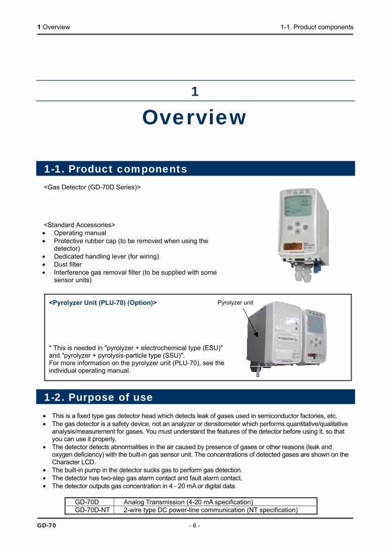
1-1. Product components <Gas Detector (GD-70D Series)> <Standard Accessories> • Operating manual • Protective rubber cap (to be removed when using the
detector) • Dedicated handling lever (for wiring) • Dust filter • Interference gas removal filter (to be supplied with some
sensor units)
<Pyrolyzer Unit (PLU-70) (Option)>
* This is needed in "pyrolyzer + electrochemical type (ESU)" and "pyrolyzer + pyrolysis-particle type (SSU)". For more information on the pyrolyzer unit (PLU-70), see the individual operating manual.
1-2. Purpose of use • This is a fixed type gas detector head which detects leak of gases used in semiconductor factories, etc. • The gas detector is a safety device, not an analyzer or densitometer which performs quantitative/qualitative
analysis/measurement for gases. You must understand the features of the detector before using it, so that you can use it properly.
• The detector detects abnormalities in the air caused by presence of gases or other reasons (leak and oxygen deficiency) with the built-in gas sensor unit. The concentrations of detected gases are shown on the Character LCD.
• The built-in pump in the detector sucks gas to perform gas detection. • The detector has two-step gas alarm contact and fault alarm contact. • The detector outputs gas concentration in 4 - 20 mA or digital data.
GD-70D Analog Transmission (4-20 mA specification) GD-70D-NT 2-wire type DC power-line communication (NT specification)
Pyrolyzer unit

1 Overview 1-3. Product specifications
- 7 - GD-70D
1-3. Product specifications
<Common Specifications>
Concentration Display
Character LCD (Digital and Bar Meter Display)
Suction Flow Rate 0.5L/min ±10% Power Display POWER lamp on (green) Displays Gas name display/Flow rate indicator/Mode display/Communication status
display/Pyrolyzer connection display Gas Alarm Display First: ALM1 lamp on (Red)/Second: ALM2 lamp on (Red) Gas Alarm Activation
Auto-reset
Gas Alarm Contact No-voltage contact 1a or 1b (2 step independent) de-energized (energized at a time of alarm) or energized (de-energized at a time of alarm)
Fault Alarm/Self Diagnosis
System abnormalities/Sensor abnormalities/Flow Rate abnormalities/Communication abnormalities/Pyrolyzer abnormalities
Fault Alarm Display
FAULT lamp on (Yellow)/Detail display
Fault Alarm Activation
Auto-reset
Fault Alarm Contact
No-voltage contact 1a or 1b de-energized (energized at a time of alarm) or energized (de-energized at a time of alarm)
Contact Capacity 125 VAC - 0.25A/24 VDC - 0.5A (Resistant load) Recommended Contact Cable
Cable of CVV, etc. (1.25sq) - max. 6-core
Functions White backlight/Alarm delay/Suppression/Zero follower/Sensitivity correction/ Flow control/Calibration history/Alarm trend history/Event history
Tube Connecting Hole
Rc1/4 (O.D Φ6-1t half-union for Teflon tube<PP>supplied)
Initial Clear Approx. 25 seconds Structure Box type/Wall mounted type External Dimensions
Approx. 70(W)x120(H)x145(D) mm (projection potions excluded)
Weight Approx. 0.9 kg Outer Color Gas detector: grey
Front door: white
<Specifications for Each Model>
Model GD-70D GD-70D-NT Transmission System
3-wire type analog transmission (Common Power Supply <Power, Signal, Common>) or 2-wire type analog transmission
2-wire type DC power-line communication
Transmission Specification
4 - 20 mA DC (no-insulation/load resistance under 300Ω)
DC power-line communication system
Recommended Transmission Cable
Shielded cable of CVVS, etc. (1.25sq) 3-core or 2-core
Shielded twisted-pair cable (1.25sq) of KPEV-S, etc. - 1P
Recommended Power Cable
Cable of CVV, etc.(1.25sq) - 2-core (Those for 3-wire type are common with the transmission cable.)
(Common with the transmission cable)
Power Supply 24VDC ±10% 24VDC ±10% (Dedicated line by blocking filter)

1 Overview 1-3. Product specifications
GD-70D - 8 -
<Specifications for Each Principle>
ESU ESU+PLU *1
SSU+PLU *1
SGU OSU *2
Detection principle
Electrochemical type
Electrochemicaltype
Pyrolysis- particle type
Semiconductor type
Galvanic cell type
Gas to be detected
Toxic gas *3 NF3 TEOS Flammable gas Toxic gas
Oxygen
Detection range
Depending on the gas to be detected
0-30ppm 0-15ppm Depending on the gas to be detected
0-25vol%
Detection system
Pump suction type
Pump suction type/pyrolysis type
Pump suction type
Alarm setpoint
Depending on the gas to be detected
10ppm(1st) 20ppm(2nd)
10ppm(1st)10ppm(2nd)
Depending on the gas to be detected
18vol%(1st) 18vol%(2nd)
Alarm accuracy
Within ±30% *4
Flammable: within ±25% Toxic: within ±30% *4
Within ±1 vol% <accuracy of the
reading> Within ±0.7 vol%
Alarm delay time
60 seconds or less *5
Flammable: 30 seconds or less Toxic: 60 seconds or less *5
5 seconds or less *6
Alarm type two-step alarm (H-HH)
two-step alarm (L-LL,L-H)
Power consumption
Approx. 1.5 W (Max. 4 W)
Approx. 2.5 W (Max. 5 W)
Approx. 1.5 W (Max. 4 W)
Operating temperatures (without sudden change)
0-40°C
Operating humidity (without condensation)
30-70%RH 30-80%RH Below 95%RH
*1 Pyrolyzer unit combination specification. For information on the specifications
of the pyrolyzer unit (PLU-70), see the individual operating manual. *2 Oxygen deficiency specification. For information on other specifications (oxygen leak
specifications), please contact us. *3 The operating temperatures/humidity may be different depending on the gas to be
detected. *4 To the alarm setpoint *5 By providing the gas 1.6 times the alarm setpoint (excluding delay in the tube and in the
communication) *6 By letting the detector detect the gas of 10 - 11 vol% (excluding delay in the tube and in
the communication). Within 30 seconds for 90% response
1 Overview 1-4. Names and functions for each part
- 9 - GD-70D
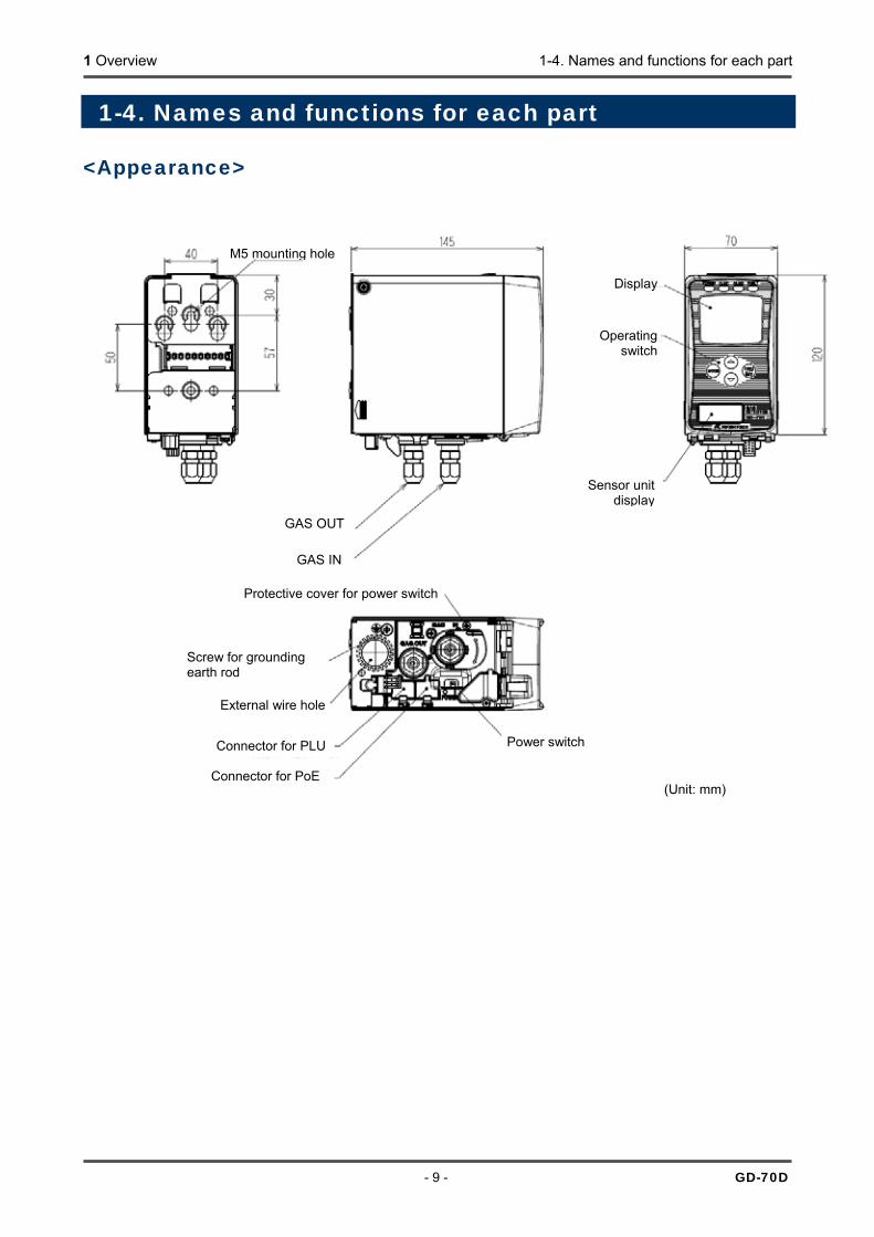
1-4. Names and functions for each part <Appearance>
(Unit: mm)
M5 mounting hole
GAS OUT
Sensor unitdisplay
Operating switch
Protective cover for power switch
External wire hole
Connector for PLU Power switch
GAS IN
Display
Screw for grounding earth rod
Connector for PoE

1 Overview 1-4. Names and functions for each part
GD-70D - 10 -
<Front Panel and Character LCD> ① MODE key Used to enter the maintenance mode.
It is also used to cancel or skip in a specific mode. ② TEST/SET key Used to enter the test mode.
It is used for value confirmation and so on in a specific mode. ③ key Used to switch screen or change a value (UP). ④ key Used to switch screen or change a value (DOWN). ⑤ Lock lever Lever to lock the main unit. Push it to attach or detach the main unit. ⑥ Sensor unit nameplate
display window Window to look at the nameplate of the sensor unit. You can identify the currently attached sensor unit.
⑦ Power lamp (POWER) Power lamp. It lights in green when the power is on. ⑧ First alarm lamp
(ALM1) First alarm lamp. It lights in red when the first alarm is reached.
⑨ Second alarm lamp (ALM2)
Second alarm lamp. It lights in red when the second alarm is reached.
⑩ Fault lamp (FAULT) Fault lamp. It lights in yellow when an abnormality is detected in the detector.⑪ Gas name display Displays the gas name in chemical formula and so on (e.g. Silane = SIH4). ⑫ Concentration value
display Displays the gas concentration and so on.
⑬ Unit display Displays the unit according to the specification (ppm, ppb, vol%, %, %LEL). ⑭ Concentration bar
indicator The detectable range (full scale = FS) is divided into 20 with bars. The increase in concentration is displayed in proportion to the full scale.
⑮ Alarm setpoint indicator
The alarm setpoints (AL1 and AL2) are indicated on the concentration bar.
⑯ Flow rate indicator Displays the suction flow rate. The center of the bars means the normal suction flow rate of 0.5 L/min.
⑰ Communication indicator
For GD-70D-NT, this indicator is displayed while transmitting data with the upper unit (TX, RX).
⑱ Maintenance indicator Displayed during the maintenance mode. When this indicator is displayed, the alarm contact is disconnected to be disabled.
⑲ Inhibit indicator Displayed when the inhibition (point skip) is set. ⑳ Pyrolyzer unit
connection indicator Displayed when the dedicated pyrolyzer unit (PLU-70) is connected.
MODE key TEST/SET key key key
Lock lever
Sensor unit nameplate display window
Power lamp
First alarm lamp Second alarm lamp
Fault lamp
⑪Gas name display
⑫Concentration value display ⑬Unit display
⑭Concentration bar indicator ⑮Alarm setpoint indicator
⑯Flow rate indicator
⑰Communication indicator
⑱Maintenance indicator
⑲Inhibit indicator
⑳Pyrolyzer unit connection indicator
1 Overview 1-5. Units description
- 11 - GD-70D
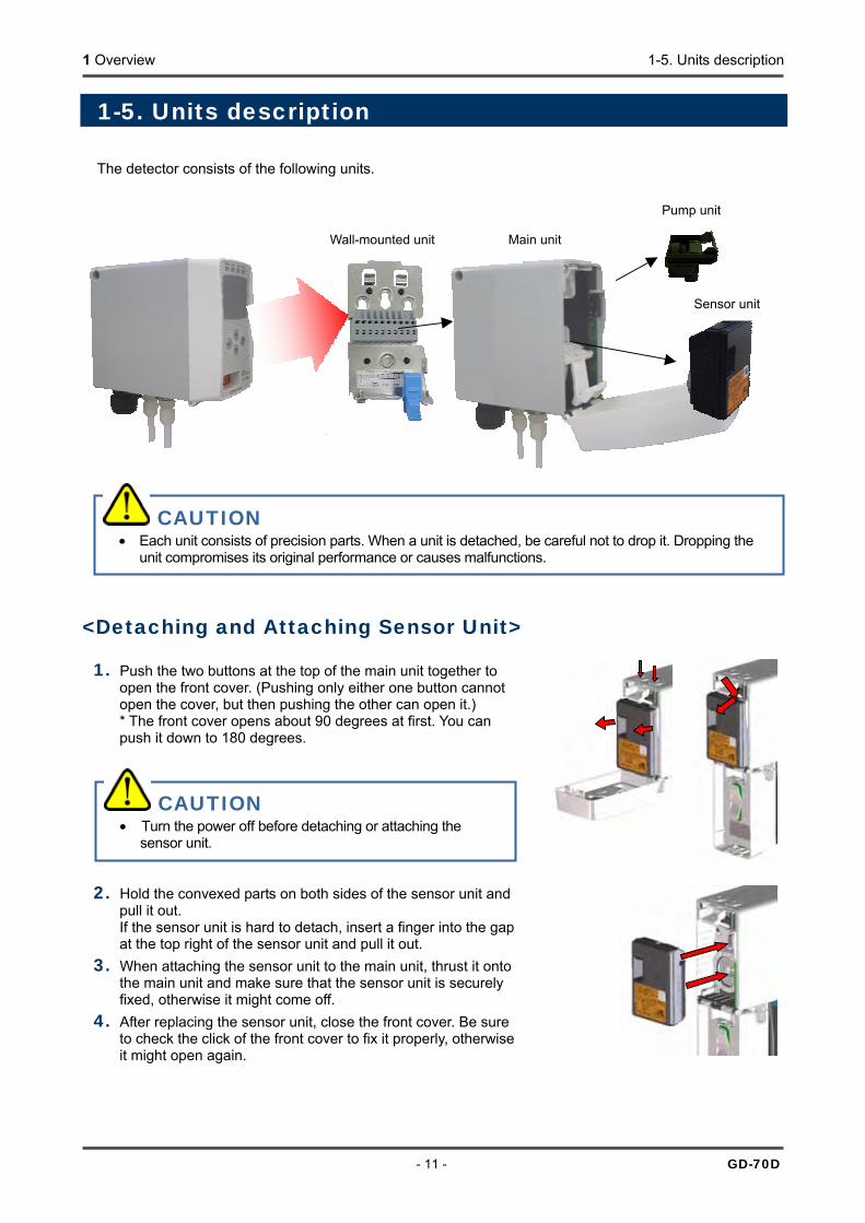
1-5. Units description The detector consists of the following units.
<Detaching and Attaching Sensor Unit> 1. Push the two buttons at the top of the main unit together to
open the front cover. (Pushing only either one button cannot open the cover, but then pushing the other can open it.) * The front cover opens about 90 degrees at first. You can push it down to 180 degrees.
2. Hold the convexed parts on both sides of the sensor unit and pull it out. If the sensor unit is hard to detach, insert a finger into the gap at the top right of the sensor unit and pull it out.
3. When attaching the sensor unit to the main unit, thrust it onto the main unit and make sure that the sensor unit is securely fixed, otherwise it might come off.
4. After replacing the sensor unit, close the front cover. Be sure to check the click of the front cover to fix it properly, otherwise it might open again.
CAUTION • Each unit consists of precision parts. When a unit is detached, be careful not to drop it. Dropping the
unit compromises its original performance or causes malfunctions.
Wall-mounted unit Main unit
Pump unit
Sensor unit
CAUTION • Turn the power off before detaching or attaching the
sensor unit.

1 Overview 1-5. Units description
GD-70D - 12 -
CAUTION • The sensor unit must be handled carefully to ensure quality as safety device. When the sensor unit is
stored, a dedicated warehouse and power equipment for the sensor unit are needed. In principal, the sensor unit must not be detached from the detector when it is handled or stored. We will take care of your sensor unit.
• Be sure that the sensor unit is not installed improperly. If a sensor unit of different specification or principle from the one shipped from the manufacturer, a message will be displayed on the LCD of the detector (C-02). If the message is displayed, check the specifications of the sensor unit.
• After the sensor unit is replaced, always perform a gas calibration (zero adjustment and span adjustment).
<How to Use Sensor Unit> A sensor unit installed in the detector is the same regardless of the detection principle, thus sensor units are interchangeable. Each sensor unit has a different color in accordance with the principle as shown below. How to handle the sensor unit is varies depending on its principle.
Electrochemical type (ESU)
• Do not disassemble the sensor unit because it contains electrolyte. If contact occurs, rinse the area immediately with a large quantity of water.
• The sensor unit identifies the direction. Put the sensor unit in the dedicated case while handling it. Do not place it on its side or upside-down.
• When a new sensor unit is installed, it must be warmed up. Although warm-up time is different depending on the type of the installed sensor, it is recommended that warm-up should be performed for three hours or more. Please contact our sales department for more information.
• The sensor unit must be stored in a clean, cool and dark place away from direct sunlight. Some types of the sensor units cannot be stored together with other units. Please contact our sales department for more information.
Pyrolysis-particle type (SSU)
• Although the sensor unit contains radioactive materials, it is certified as a specified designing certification device, which is regarded as a device having no influences on health. Observe the "Safety Manual" which stipulates conditions for the certification. To dispose of the sensor unit, you must return it to us. You do not need to take any additional actions.
• The sensor unit contains a small amount of radioactive materials. Do not disassemble it, or dispose of it like other wastes.
• The sensor unit must be put into the dedicated case specified by us, and stored away from direct sunlight in a clean place where the temperature and humidity are maintained at a normal level and where appropriate measures are introduced to prevent it from being taken out easily.
• When the sensor unit is transported out of your factory, please use a transportation company which can handle specified designing certification devices (L-type packages).
• For more information, see the "Safety Manual".
Dedicated case
Dedicated case
1 Overview 1-5. Units description
- 13 - GD-70D
Semiconductor type (SGU)
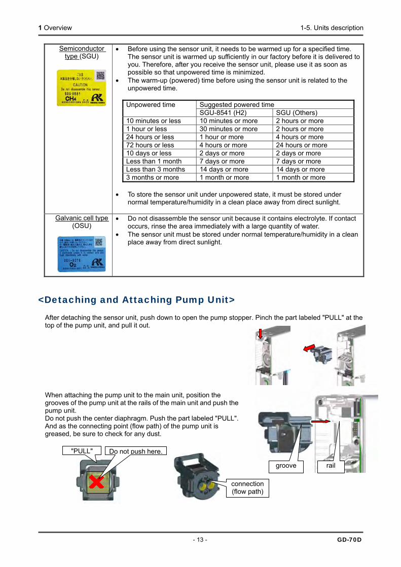
• Before using the sensor unit, it needs to be warmed up for a specified time. The sensor unit is warmed up sufficiently in our factory before it is delivered to you. Therefore, after you receive the sensor unit, please use it as soon as possible so that unpowered time is minimized.
• The warm-up (powered) time before using the sensor unit is related to the unpowered time.
Suggested powered time Unpowered time SGU-8541 (H2) SGU (Others)
10 minutes or less 10 minutes or more 2 hours or more 1 hour or less 30 minutes or more 2 hours or more 24 hours or less 1 hour or more 4 hours or more 72 hours or less 4 hours or more 24 hours or more 10 days or less 2 days or more 2 days or more Less than 1 month 7 days or more 7 days or more Less than 3 months 14 days or more 14 days or more 3 months or more 1 month or more 1 month or more
• To store the sensor unit under unpowered state, it must be stored under
normal temperature/humidity in a clean place away from direct sunlight.
Galvanic cell type (OSU)
• Do not disassemble the sensor unit because it contains electrolyte. If contact occurs, rinse the area immediately with a large quantity of water.
• The sensor unit must be stored under normal temperature/humidity in a clean place away from direct sunlight.
<Detaching and Attaching Pump Unit> After detaching the sensor unit, push down to open the pump stopper. Pinch the part labeled "PULL" at the top of the pump unit, and pull it out. When attaching the pump unit to the main unit, position the grooves of the pump unit at the rails of the main unit and push the pump unit. Do not push the center diaphragm. Push the part labeled "PULL". And as the connecting point (flow path) of the pump unit is greased, be sure to check for any dust.
connection (flow path)×
Do not push here."PULL"
groove rail
1 Overview 1-6. Block diagram
GD-70D - 14 -
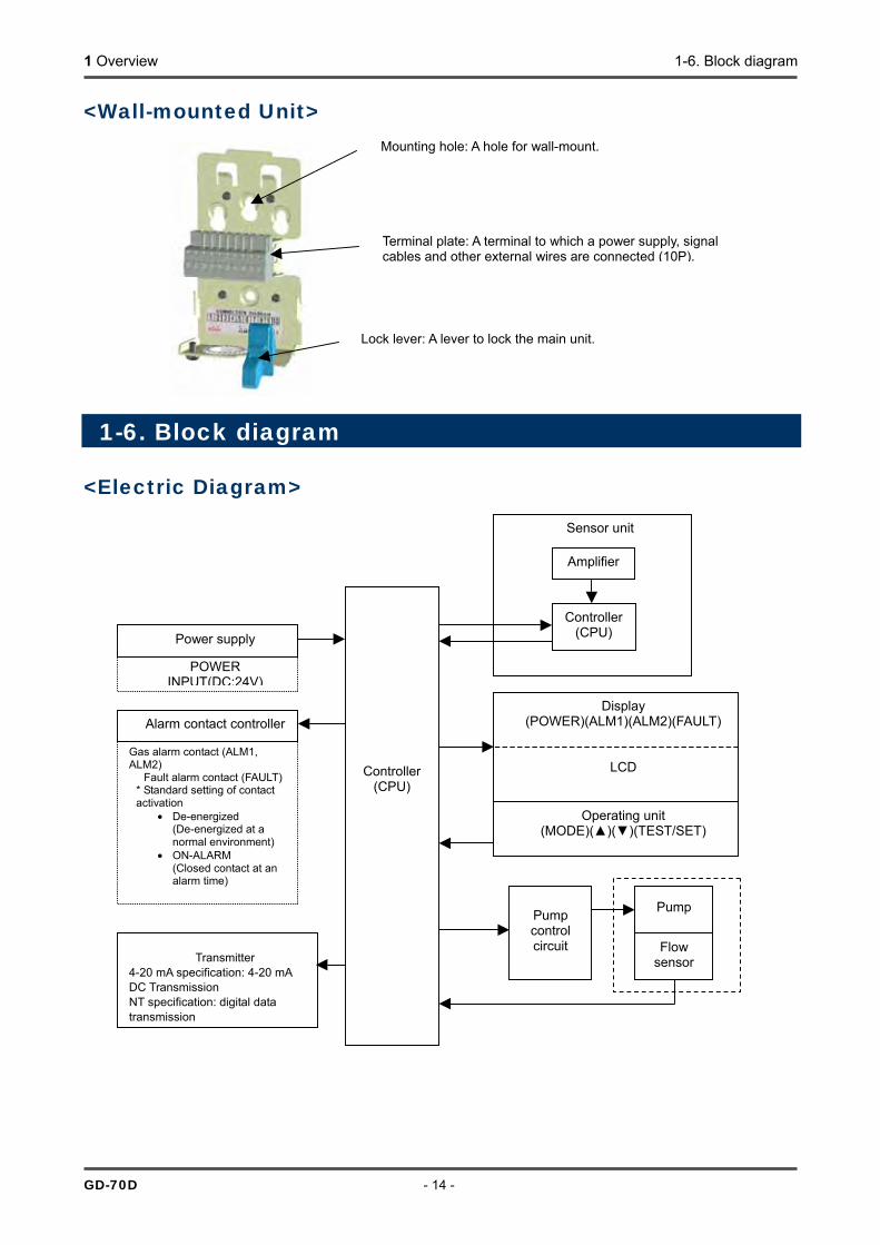
<Wall-mounted Unit>
1-6. Block diagram <Electric Diagram>
Mounting hole: A hole for wall-mount.
Terminal plate: A terminal to which a power supply, signal cables and other external wires are connected (10P).
Lock lever: A lever to lock the main unit.
Sensor unit
Controller(CPU)
Flow sensor
Pump
POWER INPUT(DC:24V)
Power supply
Gas alarm contact (ALM1, ALM2)
Fault alarm contact (FAULT) * Standard setting of contact activation
• De-energized (De-energized at a normal environment)
• ON-ALARM (Closed contact at an alarm time)
Alarm contact controller
Transmitter 4-20 mA specification: 4-20 mA DC Transmission NT specification: digital data transmission
Pump control circuit
Amplifier
Controller (CPU)
Display (POWER)(ALM1)(ALM2)(FAULT)
LCD
Operating unit (MODE)()()(TEST/SET)
1 Overview 1-6. Block diagram
- 15 - GD-70D
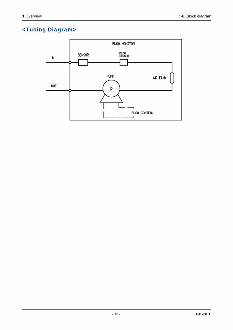
<Tubing Diagram>

2 Installation 2-1. Requirements
GD-70D - 16 -
CAUTION • This is a precision instrument. Because the detector may not provide the specified performance in
some places (environments), check the environment in the installation site, and then take appropriate actions if necessary.
• Because the detector plays an important role for safety and disaster prevention, you must install as many units of the detector as needed in appropriate points.
• Because points where gases leak and remain easily are different depending on the types of gases and the working areas, please decide carefully installation sites and the number of units to be installed.
2
Installation
2-1. Requirements Not only the first-time users but also the users who have already used the product must follow the operating precautions. Ignoring the precautions may damage the detector, resulting in inaccurate gas detection.
<Precautions for installation sites> Do not install the detector in a place with vibrations or shocks. The detector consists of sensitive electronic parts. The detector must be installed in a stable place without vibrations or shocks and it cannot drop. Do not install the detector in a place exposed to water, oil or chemicals. When you select installation sites, avoid a place where the detector is exposed to water, oil or chemicals. Do not install the detector in a place where the temperature drops below 0ºC or rises over 40ºC. The operating temperatures of the detector are 0 - 40ºC. The detector must be installed in a stable place where the operating temperatures are maintained and do not change suddenly.
CAUTION • After you received the detector, start using the detector within the specified operation start limit of the
sensor unit.

2 Installation 2-1. Requirements
- 17 - GD-70D
Do not install the detector in a place exposed to direct sunlight or sudden changes in the temperature. When you select installation sites, avoid a place where it is exposed to direct sunlight or radiant heat (infrared rays emitted from a high-temperature object), and where the temperature changes suddenly. Condensation may be formed inside the detector, or the detector cannot adjust to sudden changes in the temperature. Keep the detector (and its cables) away from noise source devices. When you select installation points, avoid a place where high-frequency/high-voltage exist. Do not install the detector in a place where maintenance of the detector cannot be performed or where handling the detector involves dangers. Regular maintenance of the detector must be performed. Do not install the detector in a place where the equipment must be stopped when maintenance is performed in its inside, where parts of the equipment must be removed to perform maintenance, or where the detector cannot be removed because tubes or racks prevent access to it. Do not install the detector in a place where maintenance involves dangers, for example, near a high-voltage cable. Do not install the detector in equipment which is not properly grounded. Before installing the detector in equipment, the equipment must be grounded properly. Do not install the detector in a place where other gases exist around it. The detector must not be installed in a place where other gases exist around it.
<Precautions for system designing> Using a stable power supply The external output and alarm contact of the detector may be activated when the power is turned on, when momentary blackout occurs, or when the system is being stabilized. In such cases, use a safety power supply, or take appropriate actions on the receiving side. The detector must be provided with the following power supply.
Power supply voltage 24 VDC ±10% (the terminal voltage of the detector) Allowed time of momentary blackout
Up to 10 millisecond (To recover from the momentary blackout for 10 millisecond or more, restart the detector.)
Example of actions To ensure continuous operation and activation, install a protective power supply outside the detector.
Others Do not use it with a power supply of large power load or high-frequency noise.
Example of actions Use a line filter to avoid the noise source if necessary.
Heat radiation designing When it is installed in the closed instrumentation board, attach ventilation fans above and below the board.
CAUTION • An unstable power supply and noise may cause malfunctions or false alarms. • The descriptions in this section must be reflected on the designing of a system using the detector.
2 Installation 2-1. Requirements
GD-70D - 18 -
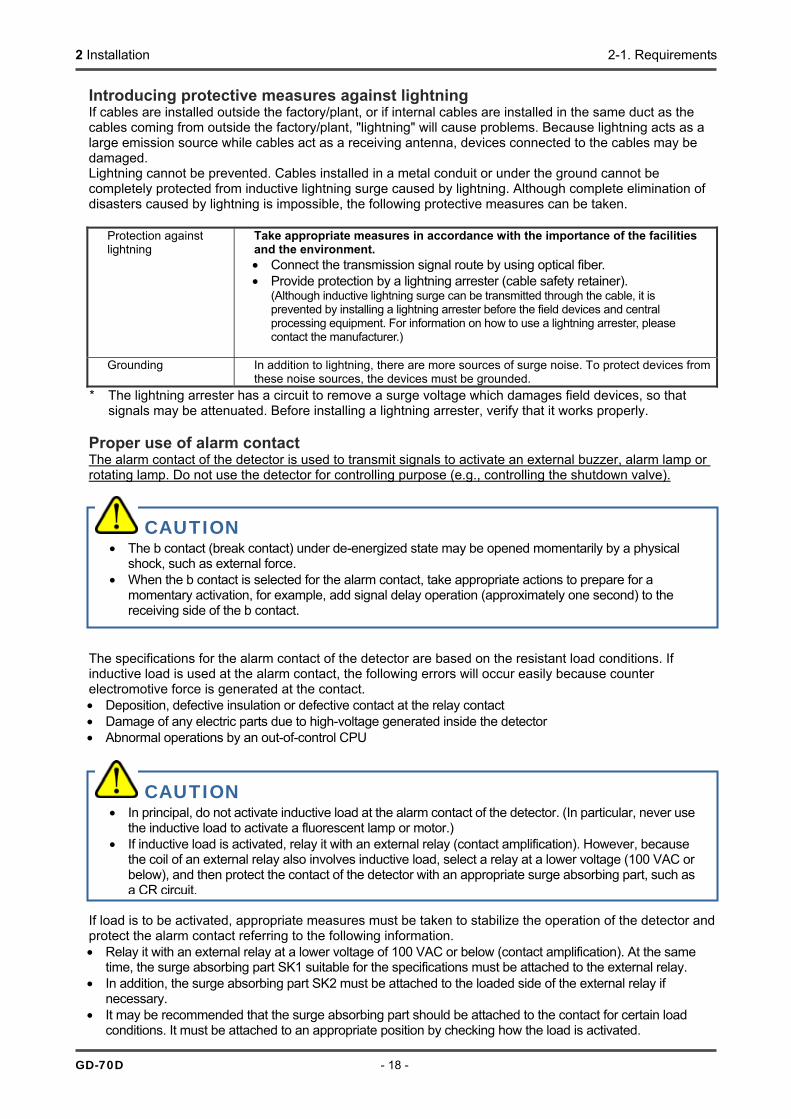
Introducing protective measures against lightning If cables are installed outside the factory/plant, or if internal cables are installed in the same duct as the cables coming from outside the factory/plant, "lightning" will cause problems. Because lightning acts as a large emission source while cables act as a receiving antenna, devices connected to the cables may be damaged. Lightning cannot be prevented. Cables installed in a metal conduit or under the ground cannot be completely protected from inductive lightning surge caused by lightning. Although complete elimination of disasters caused by lightning is impossible, the following protective measures can be taken.
Protection against lightning
Take appropriate measures in accordance with the importance of the facilities and the environment. • Connect the transmission signal route by using optical fiber. • Provide protection by a lightning arrester (cable safety retainer).
(Although inductive lightning surge can be transmitted through the cable, it is prevented by installing a lightning arrester before the field devices and central processing equipment. For information on how to use a lightning arrester, please contact the manufacturer.)
Grounding In addition to lightning, there are more sources of surge noise. To protect devices from
these noise sources, the devices must be grounded. * The lightning arrester has a circuit to remove a surge voltage which damages field devices, so that
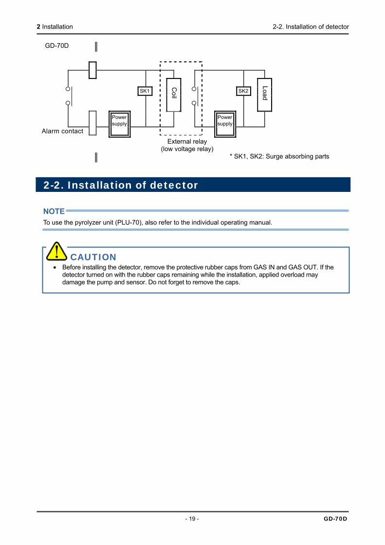
signals may be attenuated. Before installing a lightning arrester, verify that it works properly. Proper use of alarm contact The alarm contact of the detector is used to transmit signals to activate an external buzzer, alarm lamp or rotating lamp. Do not use the detector for controlling purpose (e.g., controlling the shutdown valve). The specifications for the alarm contact of the detector are based on the resistant load conditions. If inductive load is used at the alarm contact, the following errors will occur easily because counter electromotive force is generated at the contact. • Deposition, defective insulation or defective contact at the relay contact • Damage of any electric parts due to high-voltage generated inside the detector • Abnormal operations by an out-of-control CPU If load is to be activated, appropriate measures must be taken to stabilize the operation of the detector and protect the alarm contact referring to the following information. • Relay it with an external relay at a lower voltage of 100 VAC or below (contact amplification). At the same
time, the surge absorbing part SK1 suitable for the specifications must be attached to the external relay. • In addition, the surge absorbing part SK2 must be attached to the loaded side of the external relay if
necessary. • It may be recommended that the surge absorbing part should be attached to the contact for certain load
conditions. It must be attached to an appropriate position by checking how the load is activated.
CAUTION • The b contact (break contact) under de-energized state may be opened momentarily by a physical
shock, such as external force. • When the b contact is selected for the alarm contact, take appropriate actions to prepare for a
momentary activation, for example, add signal delay operation (approximately one second) to the receiving side of the b contact.
CAUTION • In principal, do not activate inductive load at the alarm contact of the detector. (In particular, never use
the inductive load to activate a fluorescent lamp or motor.) • If inductive load is activated, relay it with an external relay (contact amplification). However, because
the coil of an external relay also involves inductive load, select a relay at a lower voltage (100 VAC or below), and then protect the contact of the detector with an appropriate surge absorbing part, such as a CR circuit.
2 Installation 2-2. Installation of detector
- 19 - GD-70D
GD-70D
SK1 SK2 Power
supply Power
supply
Alarm contact External relay
(low voltage relay) * SK1, SK2: Surge absorbing parts
2-2. Installation of detector NOTE To use the pyrolyzer unit (PLU-70), also refer to the individual operating manual.
CAUTION • Before installing the detector, remove the protective rubber caps from GAS IN and GAS OUT. If the
detector turned on with the rubber caps remaining while the installation, applied overload may damage the pump and sensor. Do not forget to remove the caps.
Coil
Load

2 Installation 2-2. Installation of detector
GD-70D - 20 -
<Install Dimension and Maintenance Space>
(90)
(30)
(150)
(300)Leave the diagonal line area so that the installation space is reserved.
CAUTION • It is recommended that installation points should be away from each other for 10 mm or more.
Intervals between installation points must be at least 5 mm. • When you install more than one unit of the detector in a line, install them in a rack or wall that are not
influenced by vibrations. When the detectors are installed side-by-side, if the rack or wall in which the detectors are installed do not have enough strength, vibrations from the pumps inside the detectors cause resonance between them. In this case, take preventive actions, for example, reinforcing the rack or wall.
Maintenance space Maintenance space Maintenance space Maintenance space Maintenance spaceMaintenance space
When installing by using 2 screws When installing by using 3 screws (Unit: mm)

2 Installation 2-2. Installation of detector
- 21 - GD-70D
<Installation of Wall-mounted Unit>
Attach the wall-mounted unit in the installation surface using two or three M5 screws.
Recommended mounting screw (M5) Length of 8 mm or more Flat washer of φ10 mm or less (small round)
After the wall-mounted unit is attached to the wall, install the main unit in the wall-mounted unit.
CAUTION • The detector must be installed in the right direction to ensure its performance. Install the detector as
shown on the following example, and adjust its position so that it is placed horizontally. (* The direction of the detector must also be kept during transportation, including when it is removed temporarily or relocated.)
<Right Installation Direction>
Wall
Floor
Ceiling Wall
CAUTION • Install the unit so that its surface is in intimate contact with the wall-mounted unit. A space between
the unit and the wall-mounted unit invites unnecessary vibrations and noises.

2 Installation 2-2. Installation of detector
GD-70D - 22 -
<Detaching and Attaching Main Unit> Attaching Main Unit At the position of 10 mm above the wall hanger unit, press the main unit onto the wall hanger unit. Be sure to fit both side hooks of the wall hanger unit in the grooves of the main unit. Then press down the main unit to fix it. The lock at the bottom of the main unit clicks to fix it properly. Make sure that the top center of the wall hanger unit is above the main unit as viewed from front. Detaching Main Unit While pushing the sky blue lever toward the wall hanger unit, hold up the main unit. If you cannot move the main unit, insert a larger flathead screwdriver while pushing the lever, and you can easily detach it as shown below. Do not rotate or move up and down the flathead screwdriver. Simply insert it into the wall hanger unit.
Make sure that the top of the wall hanger unit is above the main unit.
10mm
When pressing the main unit, align the side mark with the hookof the wall hanger unit for smooth installation.
CAUTION • Be careful not to drop the main unit when detaching it.
Also, check the secure installation of the main unit after attaching it to the wall hanger unit. If the main unit is not securely installed, it might fall, causing an unexpected injury or a damage of the unit.
• Turn the power off before detaching or attaching the main unit.
The lock clicks.

2 Installation 2-3. How to wire
- 23 - GD-70D
2-3. How to wire NOTE To use the pyrolyzer unit (PLU-70), also refer to the individual operating manual.
<Recommended Cable>
For 3-wire type 4 - 20 mA (common power supply)
Shielded cable of CVVS, etc. (1.25sq) - 3-core
For 4-wire type 4 - 20 mA Power: Cable of CVV, etc. (1.25sq) - 2-core Signal: Shielded cable of CVVS, etc. (1.25sq) - 2-core
For 2-wire type DC power-line communication system (NT)
Shielded twisted-pair cable of KPEV-S, etc. (1.25sq) - 1P
For contact Cable of CVV, etc. (1.25sq) - max. 6-core
<Figure of Terminal Plate>
1 2 3 4 5 6 7 8 9 10
+ - + - 24VDC 4-20mA ALM1 contact ALM2 contact FAULT contact
NOTE For the 3-wire type (4 - 20 mA), the terminal 2 is used for common, and the terminals 2(-) and 3(+) are used to output 4 - 20 mA. For the NT specification, the terminals 3 and 4 are not used.
<Specifications of Terminal Plate>
Specifications of terminal plate • Rated voltage: 250 VDC • Rated current: 16 A
CAUTION • Be careful not to damage the internal electronic circuit when wiring. In addition, be careful not to apply
stresses on the detector when (overweight) cables are installed. • The power cables and signal cables must not be installed together with the motor power cables, etc.
When these cables must be installed together for unavoidable reasons, put the power cables and signal cables in a metal conduit. The conduit must be connected to a grounding circuit.
• When stranded wires are used, prevent wires from contacting each other. • Use the dedicated handling lever to wire.
Wiring hole
Driver slot
Conductive part
Cage clamp/spring
Top handling slot
2 Installation 2-3. How to wire
GD-70D - 24 -
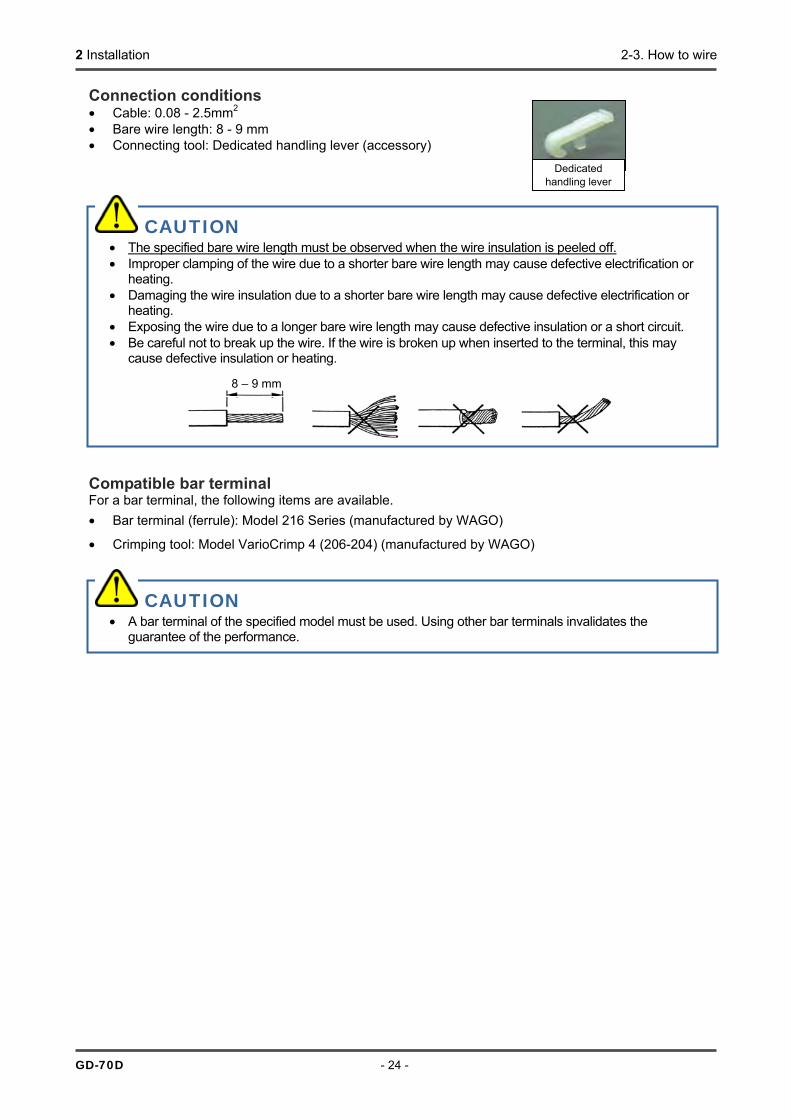
Connection conditions • Cable: 0.08 - 2.5mm2 • Bare wire length: 8 - 9 mm • Connecting tool: Dedicated handling lever (accessory)
Compatible bar terminal For a bar terminal, the following items are available. • Bar terminal (ferrule): Model 216 Series (manufactured by WAGO)
• Crimping tool: Model VarioCrimp 4 (206-204) (manufactured by WAGO)
Dedicated handling lever
CAUTION • The specified bare wire length must be observed when the wire insulation is peeled off. • Improper clamping of the wire due to a shorter bare wire length may cause defective electrification or
heating. • Damaging the wire insulation due to a shorter bare wire length may cause defective electrification or
heating. • Exposing the wire due to a longer bare wire length may cause defective insulation or a short circuit. • Be careful not to break up the wire. If the wire is broken up when inserted to the terminal, this may
cause defective insulation or heating.
8 – 9 mm
CAUTION • A bar terminal of the specified model must be used. Using other bar terminals invalidates the
guarantee of the performance.

2 Installation 2-3. How to wire
- 25 - GD-70D
<How to Connect to Terminal Plate>
When cables are connected to the connectors, use the dedicated lever or a flathead screwdriver to do it as shown below. NOTE How to Use the Dedicated Handling Lever
To check whether the wire is connected securely, pull the wire gently. (Do not pull the wire strongly.)
<How to Clamp Cables> Insert the supplied fastening-band to the hole on the wall-mounted unit as shown in the figure. Position the band so that its coarse side faces the wire. After inserting the fastening-band, fix the wire together. NOTE When an optional cable ground is used, it must be attached to the external wiring hole.
CAUTION • The right tools must be used. • In principal, one wire can be connected to one wiring
hole. • When the wire is inserted into the driver slot by mistake, it
does not contact the conductive part. This may cause defective electrification or heating.
• When the wire is inserted under the spring by mistake, it does not contact the conductive part. This may cause defective electrification or heating.
Push the dedicated handling lever to open the terminals, into which you can insert wires (one wire to one terminal).
Push the lever with your finger to lower the spring in its inside.
While holding down the lever, insert the wire into the (round) wiring hole until it reaches the deepest point.Once the lever is released, the wire is secured.
Position the band so that its coarse side faces the wire.
2 Installation 2-3. How to wire
GD-70D - 26 -
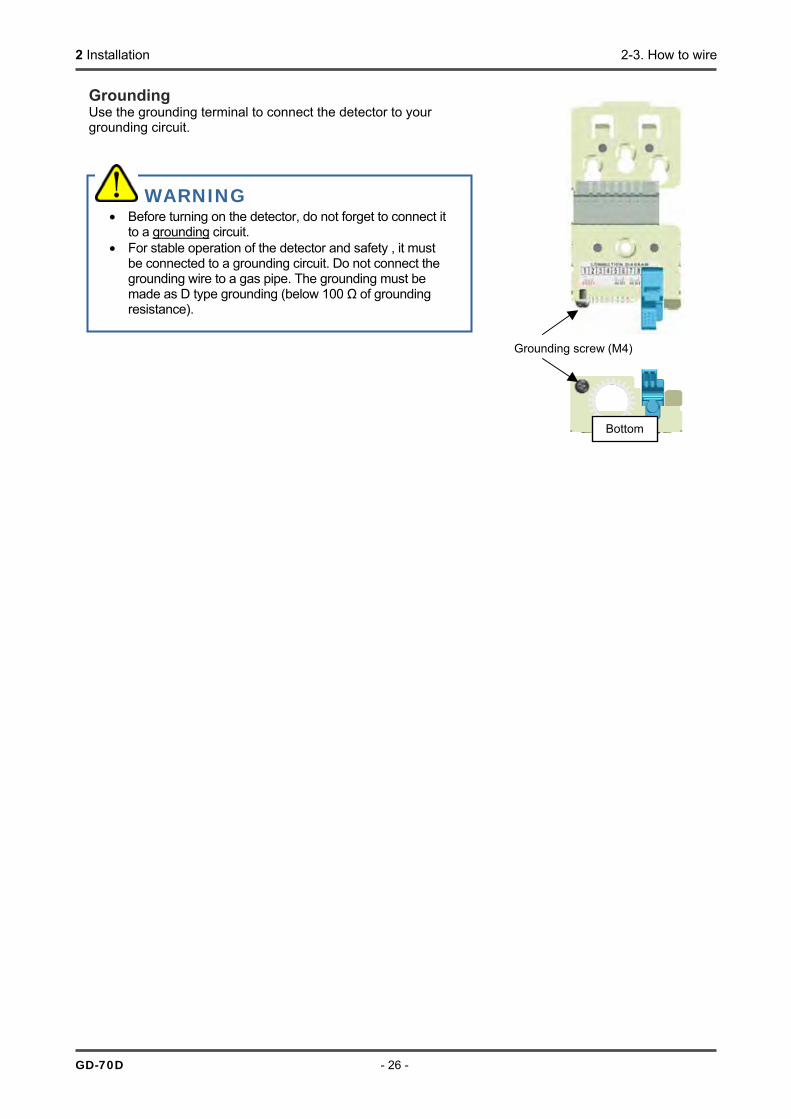
Grounding Use the grounding terminal to connect the detector to your grounding circuit.
WARNING • Before turning on the detector, do not forget to connect it
to a grounding circuit. • For stable operation of the detector and safety , it must
be connected to a grounding circuit. Do not connect the grounding wire to a gas pipe. The grounding must be made as D type grounding (below 100 Ω of grounding resistance).
Grounding screw (M4)
Bottom

2 Installation 2-3. How to wire
- 27 - GD-70D
Wiring Example Connecting to the indicator (3-wire type - 4 - 20 mA specification)
Connecting to the upper unit (DCS, PLC) (4-wire type - 4 - 20 mA specification)
Connecting to the multi-display unit (RM-70NT) (NT specification)
GD-70D
1 2 3 4 5 6 7 8 9 10
RM-593, etc.
+24V
GND
SIG
Power
supply
GD-70D
1 2 3 4 5 6 7 8 9 10
RM-593, etc.
+24V
GND
SIG
Power
supply
GD-70D-NT
1 2 3 4 5 6 7 8 9 10
Upper unit (RM-70NT)
DC24V(+) DC24V(-)
Power supply (24 VDC)
+ -
Blocking filter (B/F) (B/F)
+ -
GD-70D
1 2 3 4 5 6 7 8 9 10
Upper unit (DCS, PLC)
+ -
Power supply (24 VDC)
+-

2 Installation 2-3. How to wire
GD-70D - 28 -
<How to tube> NOTE To use the pyrolyzer unit (PLU-70), also refer to the individual operating manual. The detector has a Rc1/4 thread inside of the sampling inlet/outlet (GAS IN, GAS OUT), to which "polypropylene" unions are normally attached. Because their material is varies depending on the gas to be used, please specify the gas. The compatible tube is a Teflon tube of φ6 (OD) - φ4 (ID). The tube must be installed with the supplied inners and sleeves attached to prevent a leak. When the tube is cut, its cut point has a smaller inner diameter. Use an abrasive material to expand the cut point to the inner diameter. To remove cut-dust remaining inside of the tube, blow compressed air into the tube before connecting it to the detector. Some sample gases have highly adsorptive or corrosive features. Select the tube material taking into account of these precautions. The suction flow rate of the detector itself is approximately 0.5 L/min under the operating temperatures. When a gas is sucked from a distant point, please consult us on the tube length.
WARNING • The detector is designed to suck gases around it under the atmospheric pressure.
If excessive pressure is applied to the sampling inlet and outlet (GAS IN, GAS OUT) of the detector, detected gases may be leaked from its inside, thus leading to dangers. Be sure that excessive pressure is not applied to the detector while used.
• Detected gases must be exhausted from the detected gas exhausting outlet (GAS OUT) on the bottom of the detector to which an exhaust tube is connected, to a point regarded as a safe place.
CAUTION • The longer the tube of the GAS IN is, the longer it takes for a gas to reach the detector. Because
some gases have a highly adsorptive feature for the tube, resulting in a slow response and a lower reading than the actual value, the length of the GAS IN tube must be minimized.
• When the humidity in the sampling point is high, condensation may be formed inside of the tube. Make sure to avoid condensation when using a gas which is solved into water and corrodes contacted materials, such as a strong acid gas, because it is undetectable and furthermore may corrode internal parts. Also avoid an excessive U-shaped or V-shaped tube piping.
• Determine the inlet for the sample gas, considering the air flow of the sample gas line and the gas generating process.
• To remove dust, do not forget to attach the supplied dust filter in the middle of the tube. • You need to decide the length and material of the tube. Please contact our sales department for
more information.
union
inner
sleeve
tube

2 Installation 2-4. Relocate
- 29 - GD-70D
2-4. Relocate When the detector is relocated, select a new place in accordance with "Precautions for installation site" and "2-2. How to install". For information on wiring and tubing, see "2-3. How to wire" and "How to tube". The unpowered time must be minimized when the detector is relocated.
2-5. Disposal • A used sensor unit must be returned to us. Please return the sensor unit to our sales department. • If liquid is leaked from the electrochemical type sensor unit (ESU) or galvanic cell type sensor unit (OSU),
do not touch the liquid. The sensor unit must be put into a plastic bag to prevent leaking. If liquid is leaked from the sensor of the detector, turn "off" the power and contact our sales department immediately.
• Because the pyrolysis-particle type sensor unit (SSU) contains a small amount of radioactive materials, it must be transported appropriately (as a L-type package). When the sensor unit is returned to us, it must be handled by a transportation company which can handle L-type packages.
• When the detector is disposed of, it must be treated properly as an industrial waste in accordance with the local regulations.
CAUTION • When you use a relocated or stopped/stored detector again, do not forget to perform a gas
calibration. For information on readjustment including gas calibration, please contact our sales department.
WARNING • Do not disassemble the electrochemical type sensor unit (ESU) or the galvanic cell type sensor unit
(OSU) because they contain electrolyte. Electrolyte may cause severe skin burns if it contacts skin, while it may cause blindness if its contacts eyes. If electrolyte is adhered on you clothes, that part on your clothes is discolored or its material is decomposed. If contact occurs, rinse the area immediately with a large quantity of water.
• The pyrolysis-particle type sensor unit (SSU) must be returned to us in accordance with its "Safety Manual". We will properly dispose of it. Ignoring the "Safety Manual" will result in legal penalties.

3 How to Operate 3-1. Preparation for start-up
GD-70D - 30 -
3
How to Operate
3-1. Preparation for start-up Before connecting a power supply, read and understand the following precautions. Ignoring these precautions may cause an electric shock or damage the detector. • Connect the detector to a grounding circuit. • Check whether the wiring is connected to external circuit properly. • Check whether the power supply voltage is compliant with the specification. • Because the external contact may be activated during the adjustment, take measures to prevent an
activated contact from having influences on external circuits. • Verify that there is no clogging or leak in the connected tube. (If the connected tube is clogged, pressure is
applied to the sensor unit, causing errors and malfunctions. Please note that the reading is fluctuated in the galvanic cell type, which may result in a false alarm.)
• Verify that the filter is attached correctly. (The filter is specified based on the gas to be detected.)
3-2. How to start the detector • Before turning on the power switch, check whether the detector
is installed properly. • The power switch is protected by a cover to prevent access to it
in a normal time. To turn ON/OFF the power switch, rotate the switch cover. (Return the switch cover to the original position after the switching is completed.)
• Turn ON the power switch. • After the detector completes the start-up, it enters the detection
mode.
Power switch
OFF ON
Slide
When the switch cover is closed
When the switch cover is open

3 How to Operate 3-2. How to start the detector
- 31 - GD-70D
<Start-up Procedures (approximately 25 seconds for system check of the detector and alarm deactivation)> Power On
↓
PW A1 A2 F LCD Initial Clear
WARM UP
↓
↓ Gas Specifications Display
15.0ppm SIH4
↓
↓ Detection Mode 0.0ppm
SIH4
WARNING • When Oxygen (OSU) is selected, approximately AIR
(normal oxygen concentration) (20.9 vol%) is output after the detector is started in the atmosphere. For a specification where an alarm is triggered by the AIR (normal oxygen concentration) output (e.g., 0 - 5 vol%), be careful of an alarm issue after the detector is started.
CAUTION • Do not turn off the detector during the initial clear. The detector is reading the sensor memory during
the initial clear. • If a new sensor unit is installed or the sensor unit is replaced after the detector is started, the sensor
unit must be warmed up for a specified period which is determined depending on the type of the sensor unit. When the semiconductor type sensor unit (SGU) is selected, the suggested warm-up completion time is displayed in the maintenance mode. During the warm-up, the alarm activation and output signals are unstable. Provide a prior notification to the related sections so that they can prepare for false abnormalities.
• Because the pyrolyzer unit (PLU-70) must be warmed up for one hour, please warm it up with the detector.
• After the warm-up is completed, verify that the reading on the flow rate indicator corresponds to the specified flow rate, and then perform a gas calibration.
PW:POWER A1:ALM1 A2:ALM2 F:FAULT
:Lamp on :Lamp off
3 How to Operate 3-3. How to exit
GD-70D - 32 -
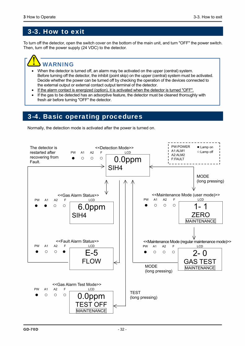
3-3. How to exit
To turn off the detector, open the switch cover on the bottom of the main unit, and turn "OFF" the power switch. Then, turn off the power supply (24 VDC) to the detector.
3-4. Basic operating procedures Normally, the detection mode is activated after the power is turned on.
WARNING • When the detector is turned off, an alarm may be activated on the upper (central) system.
Before turning off the detector, the inhibit (point skip) on the upper (central) system must be activated.Decide whether the power can be turned off by checking the operation of the devices connected to the external output or external contact output terminal of the detector.
• If the alarm contact is energized (option), it is activated when the detector is turned "OFF". • If the gas to be detected has an adsorptive feature, the detector must be cleaned thoroughly with
fresh air before turning "OFF" the detector.
<<Detection Mode>> PW A1 A2 F LCD
0.0ppm SIH4
<<Maintenance Mode (user mode)>> PW A1 A2 F LCD
1- 1 ZERO
MAINTENANCE
<<Maintenance Mode (regular maintenance mode)>>PW A1 A2 F LCD
2- 0 GAS TEST MAINTENANCE
<<Gas Alarm Test Mode>> PW A1 A2 F LCD
0.0ppm TEST OFF MAINTENANCE
<<Fault Alarm Status>> PW A1 A2 F LCD
E-5 FLOW
<<Gas Alarm Status>> PW A1 A2 F LCD
6.0ppm SIH4
MODE (long pressing)
TEST (long pressing)
The detector is restarted after recovering from Fault.
MODE (long pressing)
PW:POWER A1:ALM1 A2:ALM2 F:FAULT
:Lamp on :Lamp off

3 How to Operate 3-5. Modes
- 33 - GD-70D
<Detection mode>
Flow Rate Indicator Because the suction flow rate of the detector is automatically adjusted by the flow rate control function, the flow rate, in principal, does not need to be controlled. As shown on the figure below, when the flow rate does not correspond to the specified flow rate for some reasons, it is adjusted automatically.
3-5. Modes Details on each mode are provided as follows. (* Operations are slightly different depending on the detector type or sensor unit.)
Mode Item LCD Display Details
Detection Mode - Gas concentrationGas name
Normal state
Gas Alarm Test Mode
- Gas concentration Perform the alarm test.
Zero Adjustment (Span Adjustment)
1-1 ZERO (1-1 SPAN)
Perform the zero adjustment. (In case of oxygen 0 - 25 vol%, perform the span adjustment.)
Setting Display 1-2 CONFIRM Show the setting of typical menus. • First Alarm Setpoint (AL1) • Second Alarm Setpoint (AL2) • Alarm delay time • Zero suppression value • Zero Follower ON/OFF • Sensitivity Correction ON/OFF
Flow Rate Indicator 1-3 FLOW Show the current flow rate. Address Display 1-4 ADDRESS Show the address. Detector Version Display 1-5 70D VER Show the program version of the main unit. Unit Version Display 1-6 UNIT VER Show the program version of the sensor unit.
Maintenance Mode (user mode)
Net Version Display 1-7 NET VER Show the program version of the communication function.
WARNING • When the detector enters each mode from the detection mode while an alarm is activated, the alarm
contact is released.
CAUTION • If the automatic flow rate adjustment does not work (due to clogged tube or leak), messages such as
"FLOW" for an unstable flow rate or "E-05" for flow rate abnormalities are displayed. In this case, you must identify the causes and take appropriate actions.
Flow rate Flow rate Normal
3 How to Operate 3-5. Modes
GD-70D - 34 -
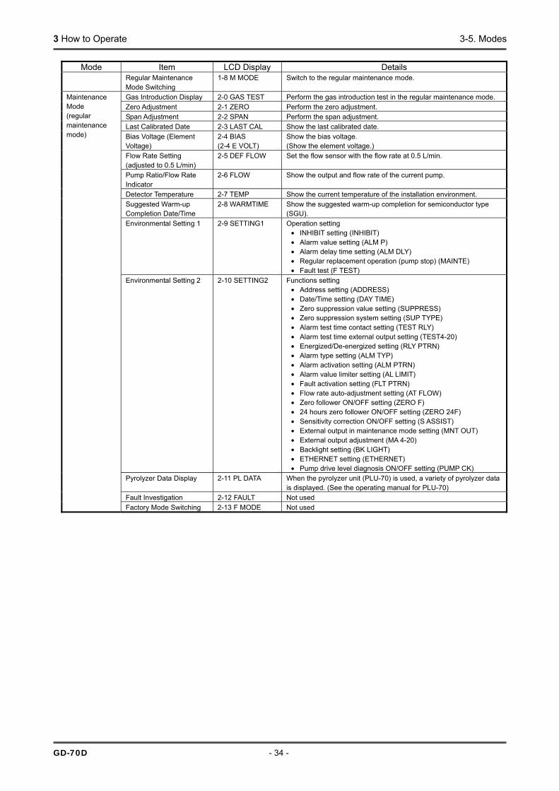
Mode Item LCD Display Details Regular Maintenance
Mode Switching 1-8 M MODE Switch to the regular maintenance mode.
Gas Introduction Display 2-0 GAS TEST Perform the gas introduction test in the regular maintenance mode. Zero Adjustment 2-1 ZERO Perform the zero adjustment. Span Adjustment 2-2 SPAN Perform the span adjustment. Last Calibrated Date 2-3 LAST CAL Show the last calibrated date. Bias Voltage (Element Voltage)
2-4 BIAS (2-4 E VOLT)
Show the bias voltage. (Show the element voltage.)
Flow Rate Setting (adjusted to 0.5 L/min)
2-5 DEF FLOW Set the flow sensor with the flow rate at 0.5 L/min.
Pump Ratio/Flow Rate Indicator
2-6 FLOW Show the output and flow rate of the current pump.
Detector Temperature 2-7 TEMP Show the current temperature of the installation environment. Suggested Warm-up Completion Date/Time
2-8 WARMTIME Show the suggested warm-up completion for semiconductor type (SGU).
Environmental Setting 1 2-9 SETTING1 Operation setting • INHIBIT setting (INHIBIT) • Alarm value setting (ALM P) • Alarm delay time setting (ALM DLY) • Regular replacement operation (pump stop) (MAINTE) • Fault test (F TEST)
Environmental Setting 2 2-10 SETTING2 Functions setting • Address setting (ADDRESS) • Date/Time setting (DAY TIME) • Zero suppression value setting (SUPPRESS) • Zero suppression system setting (SUP TYPE) • Alarm test time contact setting (TEST RLY) • Alarm test time external output setting (TEST4-20) • Energized/De-energized setting (RLY PTRN) • Alarm type setting (ALM TYP) • Alarm activation setting (ALM PTRN) • Alarm value limiter setting (AL LIMIT) • Fault activation setting (FLT PTRN) • Flow rate auto-adjustment setting (AT FLOW) • Zero follower ON/OFF setting (ZERO F) • 24 hours zero follower ON/OFF setting (ZERO 24F) • Sensitivity correction ON/OFF setting (S ASSIST) • External output in maintenance mode setting (MNT OUT) • External output adjustment (MA 4-20) • Backlight setting (BK LIGHT) • ETHERNET setting (ETHERNET) • Pump drive level diagnosis ON/OFF setting (PUMP CK)
Pyrolyzer Data Display 2-11 PL DATA When the pyrolyzer unit (PLU-70) is used, a variety of pyrolyzer data is displayed. (See the operating manual for PLU-70)
Fault Investigation 2-12 FAULT Not used
Maintenance Mode (regular maintenance mode)
Factory Mode Switching 2-13 F MODE Not used

4 Detection Mode 4-1. Gas alarm activation
- 35 - GD-70
4
Detection Mode
4-1. Gas alarm activation Gas alarm: Activated when the concentration of detected gas reaches or exceeds the alarm setpoint. <<Auto-Reset Operation>> NOTE The alarm setpoint (first alarm and second alarm) is entered before it is delivered from the factory. Although the alarm delay time (standard: 2 seconds) is enabled in the detector to prevent a false activation, you can disable it if not needed.
<Display Operation>
Gas Concentration Display In case of over the detection range (Over Scale), "∩∩∩∩" is displayed on the LCD.
Power Indicator Lamp (POWER: Green) This lights up continuously.
Alarm Indicator Lamp (ALM1: Red), (ALM2: Red) The alarm consists of two steps. Each of them lights up when respective alarm setpoint is reached or exceeded.

4 Detection Mode 4-1. Gas alarm activation
GD-70D - 36 -
<Contact Activation>
The contact is activated when the gas concentration reaches or exceeds the alarm setpoint. The contact activation is reset automatically when the gas concentration drops below the alarm setpoint.
'Alarm Pattern (H-HH)'
'Alarm Pattern (L-LL)' (* oxygen deficiency alarm)
Alarm delay time (2 seconds)
Alarm delay time (2 seconds)
Alarm lamp (ALM 1) Alarm contact (terminal plate 5, 6)
Alarm lamp (ALM 2) Alarm contact (terminal plate 7, 8)
Second alarm setpoint
First alarm setpoint Concentration Time
Alarm lamp (ALM 2) Alarm contact (terminal plate 7, 8)
Alarm delay time (2 seconds)
Alarm delay time (2 seconds)
Alarm lamp (ALM 1) Alarm contact (terminal plate 5, 6)
First alarm setpoint
Second alarm setpoint
Concentration
Time
4 Detection Mode 4-2. Fault alarm activation
- 37 - GD-70D
<Response to Gas Alarm>
In case of responding to a leaked gas When a gas alarm is triggered, take actions in accordance with your management rules of gas alarm. Normally, take the following actions. • Check the reading of the detector. NOTE If a gas leak is momentary, the reading may already have dropped when you check it. In addition, when the alarm is triggered by noise or other incidental conditions other than a gas, the reading may have already dropped. • Based on your management rules of gas alarm, no one can be allowed to access the monitored zone to
ensure safety. • If the Gas Concentration Display continues to be shown, close the main valve of the gas, and then verify
that the gas concentration reading dropped. • Equipped with a protective gear to avoid dangers caused by possibly remaining gases, before accessing
the gas leak point, and then check whether gases remain by using a portable gas detector. • If you can determine that the point is free from dangers, take actions to fix the gas leak.
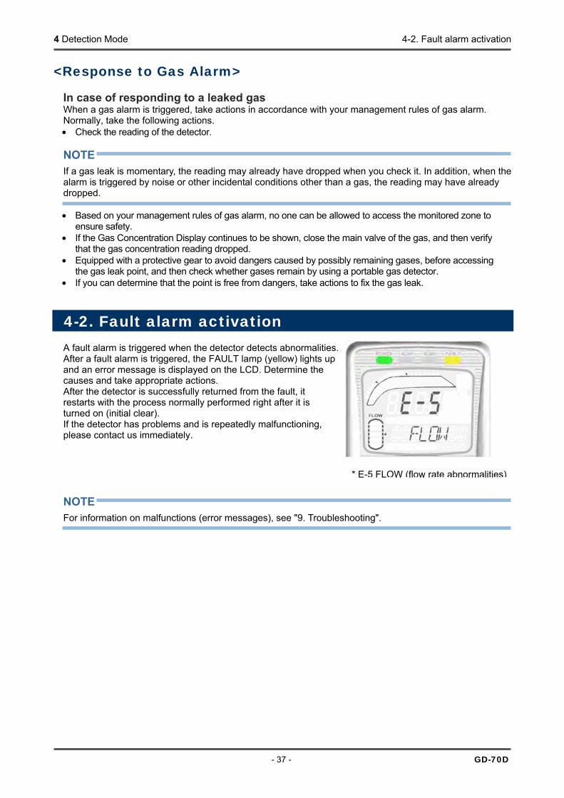
4-2. Fault alarm activation A fault alarm is triggered when the detector detects abnormalities. After a fault alarm is triggered, the FAULT lamp (yellow) lights up and an error message is displayed on the LCD. Determine the causes and take appropriate actions. After the detector is successfully returned from the fault, it restarts with the process normally performed right after it is turned on (initial clear). If the detector has problems and is repeatedly malfunctioning, please contact us immediately. NOTE For information on malfunctions (error messages), see "9. Troubleshooting".
* E-5 FLOW (flow rate abnormalities)
4 Detection Mode 4-3. External output operation
GD-70D - 38 -
4-3. External output operation
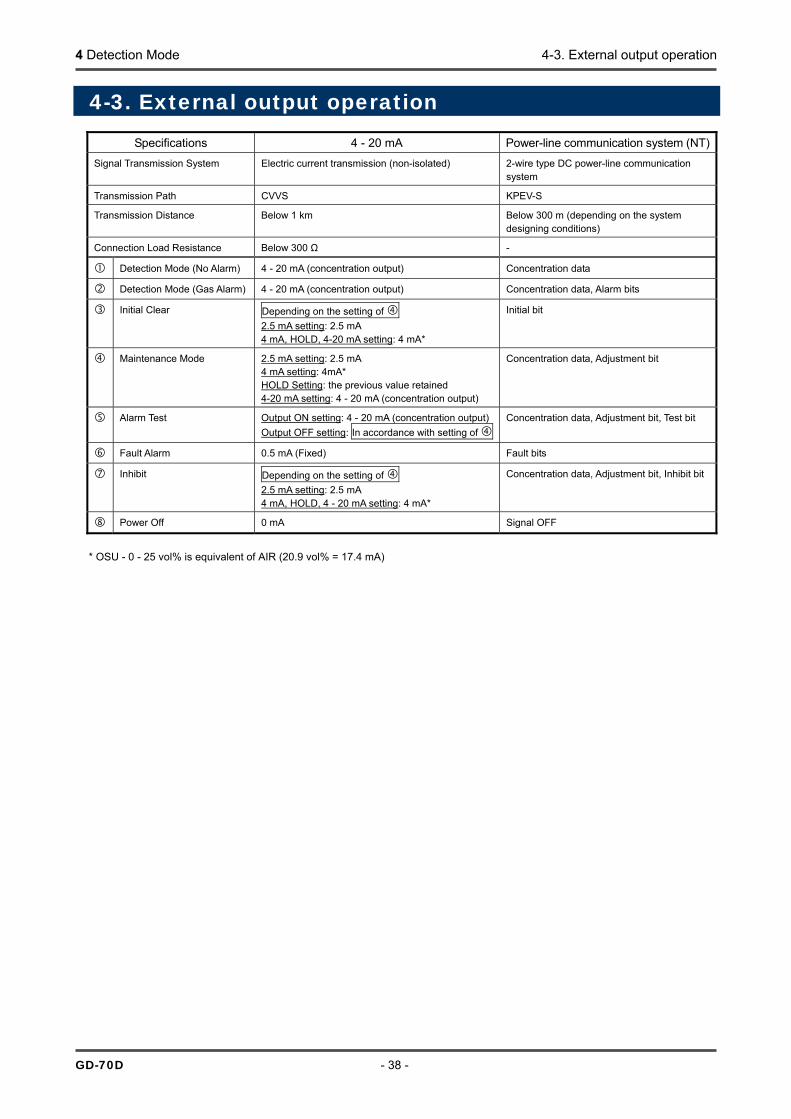
Specifications 4 - 20 mA Power-line communication system (NT)Signal Transmission System Electric current transmission (non-isolated) 2-wire type DC power-line communication
system
Transmission Path CVVS KPEV-S
Transmission Distance Below 1 km Below 300 m (depending on the system designing conditions)
Connection Load Resistance Below 300 Ω -
Detection Mode (No Alarm) 4 - 20 mA (concentration output) Concentration data
Detection Mode (Gas Alarm) 4 - 20 mA (concentration output) Concentration data, Alarm bits
Initial Clear Depending on the setting of 2.5 mA setting: 2.5 mA 4 mA, HOLD, 4-20 mA setting: 4 mA*
Initial bit
Maintenance Mode 2.5 mA setting: 2.5 mA 4 mA setting: 4mA* HOLD Setting: the previous value retained 4-20 mA setting: 4 - 20 mA (concentration output)
Concentration data, Adjustment bit
Alarm Test Output ON setting: 4 - 20 mA (concentration output)Output OFF setting: In accordance with setting of
Concentration data, Adjustment bit, Test bit
Fault Alarm 0.5 mA (Fixed) Fault bits
Inhibit Depending on the setting of 2.5 mA setting: 2.5 mA 4 mA, HOLD, 4 - 20 mA setting: 4 mA*
Concentration data, Adjustment bit, Inhibit bit
Power Off 0 mA Signal OFF
* OSU - 0 - 25 vol% is equivalent of AIR (20.9 vol% = 17.4 mA)
4 Detection Mode 4-3. External output operation
- 39 - GD-70D
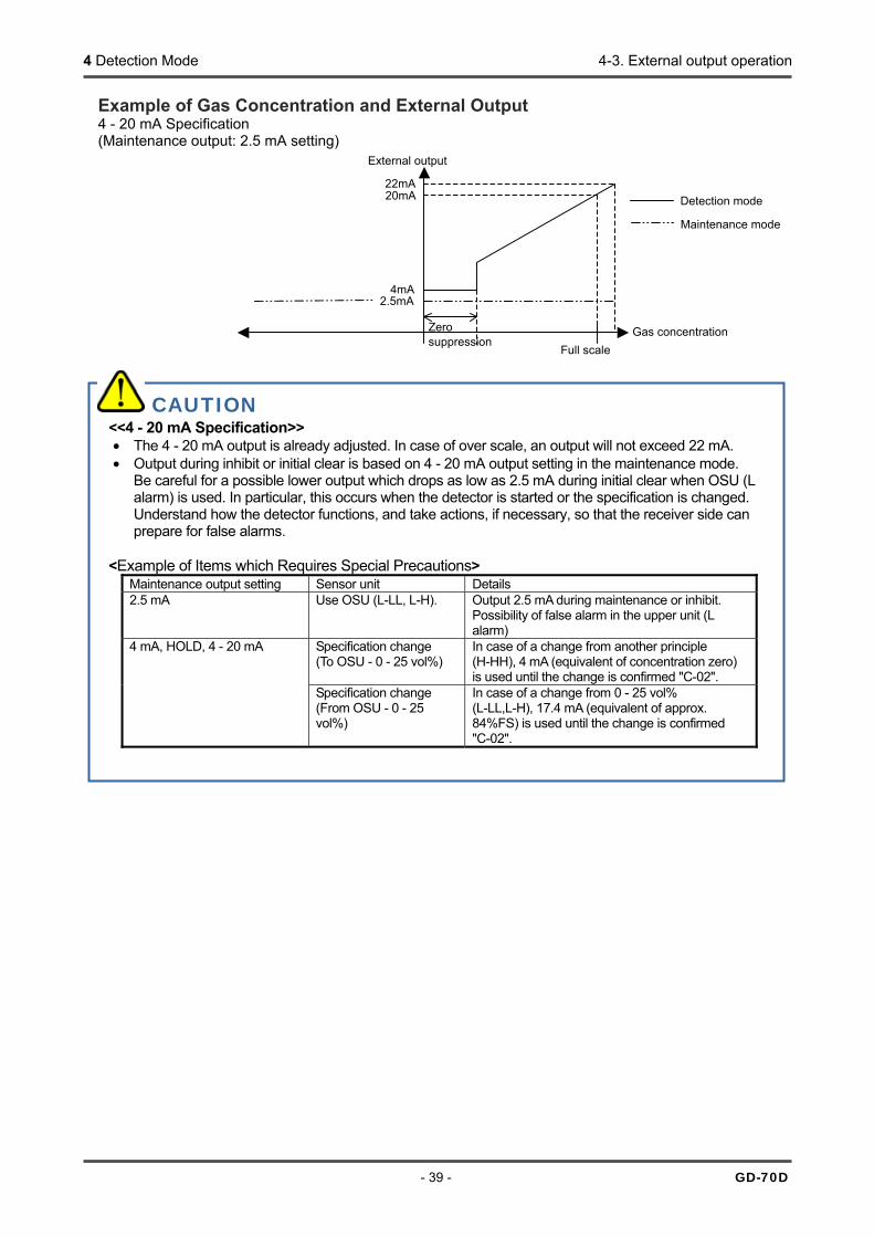
Example of Gas Concentration and External Output 4 - 20 mA Specification (Maintenance output: 2.5 mA setting)
CAUTION <<4 - 20 mA Specification>> • The 4 - 20 mA output is already adjusted. In case of over scale, an output will not exceed 22 mA. • Output during inhibit or initial clear is based on 4 - 20 mA output setting in the maintenance mode.
Be careful for a possible lower output which drops as low as 2.5 mA during initial clear when OSU (L alarm) is used. In particular, this occurs when the detector is started or the specification is changed. Understand how the detector functions, and take actions, if necessary, so that the receiver side can prepare for false alarms.
<Example of Items which Requires Special Precautions>
Maintenance output setting Sensor unit Details 2.5 mA Use OSU (L-LL, L-H). Output 2.5 mA during maintenance or inhibit.
Possibility of false alarm in the upper unit (L alarm)
Specification change (To OSU - 0 - 25 vol%)
In case of a change from another principle (H-HH), 4 mA (equivalent of concentration zero) is used until the change is confirmed "C-02".
4 mA, HOLD, 4 - 20 mA
Specification change (From OSU - 0 - 25 vol%)
In case of a change from 0 - 25 vol% (L-LL,L-H), 17.4 mA (equivalent of approx. 84%FS) is used until the change is confirmed "C-02".
2.5mA4mA
20mA 22mA
Full scaleGas concentration
External output
Zero suppression
Detection mode
Maintenance mode
4 Detection Mode 4-4. Other functions
GD-70D - 40 -
4-4. Other functions
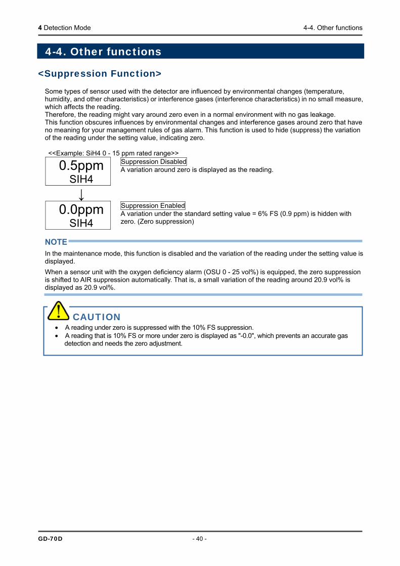
<Suppression Function> Some types of sensor used with the detector are influenced by environmental changes (temperature, humidity, and other characteristics) or interference gases (interference characteristics) in no small measure, which affects the reading. Therefore, the reading might vary around zero even in a normal environment with no gas leakage. This function obscures influences by environmental changes and interference gases around zero that have no meaning for your management rules of gas alarm. This function is used to hide (suppress) the variation of the reading under the setting value, indicating zero. <<Example: SiH4 0 - 15 ppm rated range>>
0.5ppm SIH4
Suppression Disabled A variation around zero is displayed as the reading.
↓
0.0ppm SIH4
Suppression Enabled A variation under the standard setting value = 6% FS (0.9 ppm) is hidden with zero. (Zero suppression)
NOTE In the maintenance mode, this function is disabled and the variation of the reading under the setting value is displayed. When a sensor unit with the oxygen deficiency alarm (OSU 0 - 25 vol%) is equipped, the zero suppression is shifted to AIR suppression automatically. That is, a small variation of the reading around 20.9 vol% is displayed as 20.9 vol%.
CAUTION • A reading under zero is suppressed with the 10% FS suppression. • A reading that is 10% FS or more under zero is displayed as "-0.0", which prevents an accurate gas
detection and needs the zero adjustment.

4 Detection Mode 4-4. Other functions
- 41 - GD-70D
<Zero Follower Function> Some types of sensor used with the detector might have sensitivity variations after being used for a long period. This function corrects the variation of the reading at the zero point (zero drift) among the sensitivity variations over time by a program manipulation to stabilize the zero point, and works on the electrochemical type (ESU) and pyrolysis-particle type (SSU).
<Sensitivity Correction Function>
Some types of sensor used with the detector might have sensitivity variations after being used for a long period. This function compensates the degradation of the gas sensitivity among the sensitivity variations over time. It works on the electrochemical type (ESU) and makes the span adjustment by a program manipulation based on the principled degradation pattern.
* The zero adjustment is made periodically.
Zero Follower On
Zero Follower Off
* The zero drift of the sensor appears as the reading.
Reading
Zero point
0 Time
↓
Zero point
0
Reading
Time
Sensitivity Correction Off
* The sensor sensitivity becomes degraded.
Sensitivity Correction On
* The span is lifted up periodically.
↓
0 Time
Gas correction
Reading
Gas correction
0
Reading
Time

4 Detection Mode 4-4. Other functions
GD-70D - 42 -
<Calibration History/Alarm Trend History/Event History Functions>
The detector and the sensor unit have their own history functions. To use these functions, contact our sales department.
<Sensor Unit Automatic Recognition Function> The detector has the function to automatically recognize the sensor unit when the sensor unit is replaced or the specification is changed. When a sensor unit with a different serial number or with a different principle or specification is attached, one of the following messages is displayed for helping the correct installation.
C-01 CHG UNIT
MAINTENANCE
Unit Replacement Displayed when a unit with the same specification (principle, type, range, and so on) is attached (e.g. in a regular replacement). Press the MODE key to recognize the new sensor unit and start the monitor.
↓
C-02 CHG SPEC
MAINTENANCE
Specification Change Displayed when a unit with a different specification (principle, type, range, and so on) from the previous one is attached. Press the MODE key to recognize the unit with the new specification and start themonitor. If you do not intend the specification change, this message might mean the installation error. Check the correct installation.
CAUTION If you confirm the specification change (principle, sensor type, detected gases, detectable range, and so on) of the sensor unit for "C-02", the specification of the gas detector head is changed. Note that it resets the alarm setpoint (ALM P) as well as the following parameters to the standard setting values. If you want to use nonstandard setting values, set them in the maintenance mode. • Alarm delay time setting (ALM DLY) • Suppression value (SUPPRESS) • Alarm type (ALM TYP) ...... The OSU specification includes "L-LL", "L-H", and "H-HH".
<Standard Setting Values by Principle>
ESU SSU SGU OSU (0 - 25 vol%)
OSU (0 - 5 vol%)
OSU (0 - 50 vol%)
Alarm delay 2 seconds 2 seconds 2 seconds 2 seconds 2 seconds 2 seconds Suppression value
6 %FS 2 ppm (TEOS)
10 %FS 0.5 vol% (AIR supp)
0 vol% 0 vol%
Alarm type H-HH H-HH H-HH L-LL H-HH H-HH "Change from OSU (L-LL alarm)" or "change to OSU (L-LL alarm)" reverses the direction of the alarm. It requires special care because the previous settings are kept for the external output and other settings in the maintenance mode. Immediately after "C-02" is confirmed with the MODE key, the initial clear is started and the new actions are enabled. (The initial clear output is shifted together.)
CAUTION The sensitivity correction is just an auxiliary function. It uniformly lifts the span up based on the principled degradation pattern only and cannot consider the sensitivity variation of an individual sensor. To correct the sensitivity variation of an individual sensor, you must make the regular span adjustment using an adjustment gas.
5 Alarm Test Mode
- 43 - GD-70
5
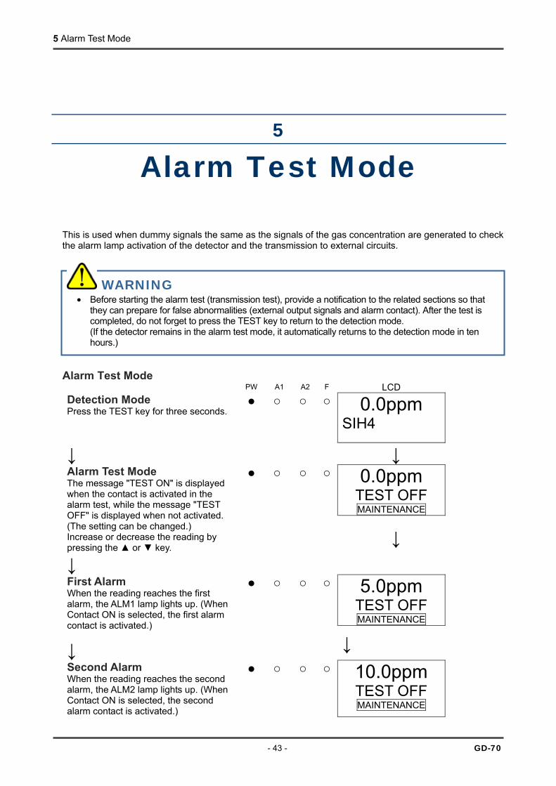
Alarm Test Mode This is used when dummy signals the same as the signals of the gas concentration are generated to check the alarm lamp activation of the detector and the transmission to external circuits.
Alarm Test Mode PW A1 A2 F LCD
Detection Mode Press the TEST key for three seconds.
0.0ppm SIH4
↓ ↓
0.0ppm TEST OFF MAINTENANCE
Alarm Test Mode The message "TEST ON" is displayed when the contact is activated in the alarm test, while the message "TEST OFF" is displayed when not activated. (The setting can be changed.) Increase or decrease the reading by pressing the or key.
↓
↓
5.0ppm TEST OFF MAINTENANCE
First Alarm When the reading reaches the first alarm, the ALM1 lamp lights up. (When Contact ON is selected, the first alarm contact is activated.)
↓ ↓
Second Alarm When the reading reaches the second alarm, the ALM2 lamp lights up. (When Contact ON is selected, the second alarm contact is activated.)
10.0ppm TEST OFF MAINTENANCE
WARNING • Before starting the alarm test (transmission test), provide a notification to the related sections so that
they can prepare for false abnormalities (external output signals and alarm contact). After the test is completed, do not forget to press the TEST key to return to the detection mode. (If the detector remains in the alarm test mode, it automatically returns to the detection mode in ten hours.)
6 User Mode
GD-70 - 44 -
6
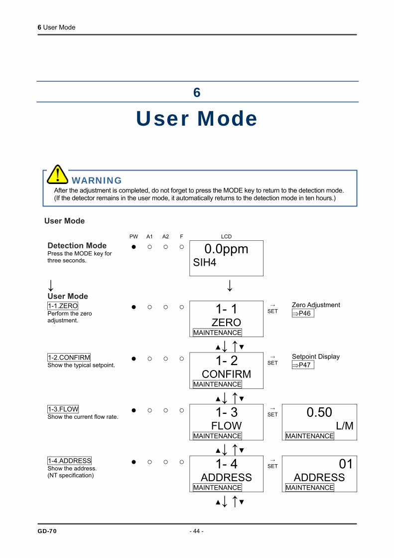
User Mode User Mode
PW A1 A2 F LCD
Detection Mode Press the MODE key for three seconds.
0.0ppm SIH4
↓ User Mode
↓
1-1.ZERO Perform the zero adjustment.
1- 1 ZERO
MAINTENANCE
→ SET
Zero Adjustment ⇒P46
↓ ↑
1-2.CONFIRM Show the typical setpoint.
1- 2 CONFIRM
MAINTENANCE
→ SET
Setpoint Display ⇒P47
↓ ↑
1-3.FLOW Show the current flow rate.
1- 3 FLOW
MAINTENANCE
→ SET 0.50
L/MMAINTENANCE
↓ ↑
1-4.ADDRESS Show the address. (NT specification)
1- 4 ADDRESS
MAINTENANCE
→ SET 01
ADDRESS MAINTENANCE
↓ ↑
WARNING After the adjustment is completed, do not forget to press the MODE key to return to the detection mode. (If the detector remains in the user mode, it automatically returns to the detection mode in ten hours.)

6 User Mode
- 45 - GD-70D
1-5.70D VER Show the program version of the main unit.
1- 5 70D VER
MAINTENANCE
→ SET 01234
56ABMAINTENANCE
↓ ↑
1-6.UNIT VER Show the program version of the installed sensor unit.
1- 6 UNIT VER
MAINTENANCE
→ SET 01234
56ABMAINTENANCE
↓ ↑
↓ ↑
1-7.NET VER Show the program version of the communication function. (NT specification)
1- 7 NET VER
MAINTENANCE
→ SET 01234
----MAINTENANCE
↓ ↑
1-8.M MODE Switch to the regular maintenance mode.
1- 8 M MODE
MAINTENANCE
→ SET
See "7. Regular Maintenance Mode".
↓ ↑
To 1-1.ZERO
6 User Mode
GD-70D - 46 -
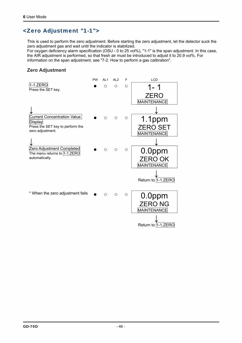
<Zero Adjustment "1-1">
This is used to perform the zero adjustment. Before starting the zero adjustment, let the detector suck the zero adjustment gas and wait until the indicator is stabilized. For oxygen deficiency alarm specification (OSU - 0 to 25 vol%), "1-1" is the span adjustment. In this case, the AIR adjustment is performed, so that fresh air must be introduced to adjust it to 20.9 vol%. For information on the span adjustment, see "7-2. How to perform a gas calibration". Zero Adjustment
PW AL1 AL2 F LCD 1-1.ZERO Press the SET key.
1- 1 ZERO
MAINTENANCE
↓ ↓ Current Concentration Value Display Press the SET key to perform the zero adjustment.
1.1ppm ZERO SET MAINTENANCE
↓ ↓ Zero Adjustment Completed The menu returns to 1-1.ZERO automatically.
0.0ppm ZERO OK
MAINTENANCE
↓ Return to 1-1.ZERO * When the zero adjustment fails 0.0ppm
ZERO NG MAINTENANCE
↓ Return to 1-1.ZERO

6 User Mode
- 47 - GD-70D
<Setpoint Indicator "1-2">
This is used to check important setpoints. Setpoint Display
PW A1 A2 F LCD
1- 2 CONFIRM
MAINTENANCE 1-2.CONFIRM
Press the SET key.
↓ ↓ First Alarm Setpoint Indicator 5.0ppm
AL 1 MAINTENANCE
↓ ↑
Second Alarm Setpoint Indicator 10.0ppm AL 2
MAINTENANCE
↓ ↑
Alarm Delay Time Display (seconds)
2 ALM DLY
MAINTENANCE
↓ ↑
Zero Suppression Value Display 0.9ppm SUPPRESS MAINTENANCE
↓ ↑
Zero Follower ON/OFF Display (If ESU or SSU installed)
ON ZERO F
MAINTENANCE
↓ ↑
Sensitivity Correction ON/OFF Display (If ESU installed)
OFF S ASSIST
MAINTENANCE
↓ ↑
To First Alarm Setpoint Indicator

7 Regular Maintenance Mode
GD-70 - 48 -
7
Regular Maintenance Mode
Mode Item LCD Display Details Gas Introduction Display 2-0 GAS TEST Perform the gas introduction test in the regular
maintenance mode. Zero Adjustment ⇒P65
2-1 ZERO Perform the zero adjustment.
Span Adjustment ⇒P65
2-2 SPAN Perform the span adjustment.
Last Calibrated Date
2-3 LAST CAL Show the last calibrated date.
Bias Voltage (Element Voltage)
2-4 BIAS (2-4 E VOLT)
Show the bias voltage. (Show the element voltage.)
Flow Rate Setting (adjusted to 0.5 L/min) ⇒P67
2-5 DEF FLOW
Set the flow sensor with the flow rate at 0.5 L/min.
Pump Ratio/Flow Rate Indicator ⇒P67
2-6 FLOW Show the output and flow rate of the current pump.
Detector Temperature
2-7 TEMP Show the current temperature of the installation environment.
Suggested Warm-up Completion Date/Time
2-8 WARMTIME
Show the suggested warm-up completion for semiconductor type (SGU).
Maintenance Mode (regular maintenance mode)
Environmental Setting 1 ⇒P53
2-9 SETTING1 Operation setting • INHIBIT setting (INHIBIT) • Alarm value setting (ALM P) ⇒P54 • Alarm delay time setting (ALM DLY) • Regular replacement operation (pump stop) (MAINTE) • Fault alarm test (F TEST) ⇒P54
WARNING After the adjustment is completed, do not forget to press the MODE key to return to the detection mode. (If the detector remains in the maintenance mode, it automatically returns to the detection mode in ten hours.)

7 Regular Maintenance Mode
- 49 - GD-70D
Mode Item LCD Display Details Environmental Setting 2 ⇒P55
2-10 SETTING2
Functions setting • Address setting (ADDRESS) • Date/Time setting (DAY TIME) ⇒P60 • Zero suppression value setting (SUPPRESS) • Zero suppression system setting (SUP TYPE) • Alarm test time contact setting (TEST RLY) • Alarm test time external output setting (TEST4-20) • Energized/De-energized setting (RLY PTRN) ⇒P61 • Alarm type setting (ALM TYP) • Alarm activation setting (ALM PTRN) • Alarm value limiter setting (AL LIMIT) • Fault activation setting (FLT PTRN) • Flow rate auto-adjustment setting (AT FLOW) • Zero follower ON/OFF setting (ZERO F) • 24 hours zero follower ON/OFF setting (ZERO 24F)• Sensitivity correction ON/OFF setting (S ASSIST) • External output in maintenance mode setting (MNT OUT) • External output adjustment (MA 4-20) • Backlight setting (BK LIGHT) • ETHERNET setting (ETHERNET) • Pump drive level diagnosis ON/OFF setting (PUMP CK)
Pyrolyzer Data Display 2-11 PL DATA When the pyrolyzer unit (PLU-70) is used, a variety of pyrolyzer data is displayed. (See the operating manual for PLU-70)
Fault Investigation
2-12 FAULT Not used
Factory Mode Switching
2-13 F MODE Not used

7 Regular Maintenance Mode
GD-70D - 50 -
Regular Maintenance Mode
PW A1 A2 F LCD User Mode In "1-8.M MODE", press the SET key.
1- 8 M MODE
MAINTENANCE
↓ ↓ Then press the SET key again for three seconds. - - - -
M MODE MAINTENANCE
↓ Regular Maintenance Mode
↓
2- 0 GAS TEST
MAINTENANCE
→ SET 0.2ppm
GAS TESTMAINTENANCE
↓(Alternate Display)↑
0.2ppm SIH4 MAINTENANCE
2-0.GAS TEST Perform a test with the gas. Similar to the detection mode, the reading changes and the alarm lamp lights up after the gas is introduced, but the contact is not activated.
| ↑ | |
↓ |
2- 1 ZERO
MAINTENANCE
→ SET
Zero Adjustment ⇒P65 2-1.ZERO
Perform the zero adjustment.
↓ ↑ 2- 2
SPAN MAINTENANCE
→ SET
Span Adjustment ⇒P66 2-2.SPAN
Perform the span adjustment.
↓ ↑ 2- 3
LAST CAL MAINTENANCE
→ SET 12:00
2009.01.01MAINTENANCE
2-3.LAST CAL Show the last calibrated date.
↓ ↑ 2- 4
BIAS MAINTENANCE
→ SET 0 mV
BIAS MAINTENANCE
2-4.BIAS Show the bias voltage "BIAS" of electrochemical type (ESU) or the element voltage "EVOLT" of semiconductor type (SGU). ↓ ↑
PW: POWER A1: ALM1 A2: ALM2 F: FAULT
: Lamp on : Lamp off
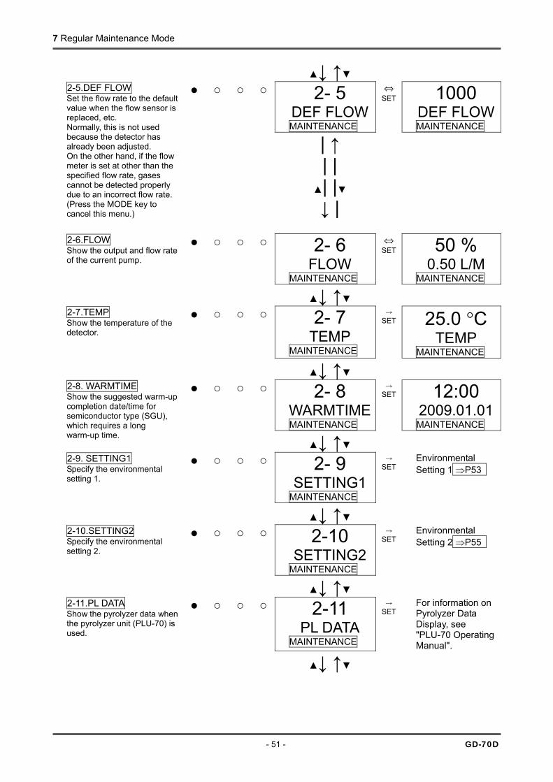
7 Regular Maintenance Mode
- 51 - GD-70D
↓ ↑ 2- 5
DEF FLOWMAINTENANCE
⇔ SET 1000
DEF FLOWMAINTENANCE
2-5.DEF FLOW Set the flow rate to the default value when the flow sensor is replaced, etc. Normally, this is not used because the detector has already been adjusted. On the other hand, if the flow meter is set at other than the specified flow rate, gases cannot be detected properly due to an incorrect flow rate. (Press the MODE key to cancel this menu.)
| ↑ | |
| |
↓ |
2- 6 FLOW
MAINTENANCE
⇔ SET 50 %
0.50 L/M MAINTENANCE
2-6.FLOW Show the output and flow rate of the current pump.
↓ ↑ 2- 7
TEMP MAINTENANCE
→ SET 25.0 °C
TEMP MAINTENANCE
2-7.TEMP Show the temperature of the detector.
↓ ↑ 2- 8
WARMTIMEMAINTENANCE
→ SET 12:00
2009.01.01MAINTENANCE
2-8. WARMTIME Show the suggested warm-up completion date/time for semiconductor type (SGU), which requires a long warm-up time. ↓ ↑
2- 9 SETTING1
MAINTENANCE
→ SET
Environmental Setting 1 ⇒P53
2-9. SETTING1 Specify the environmental setting 1.
↓ ↑ 2-10
SETTING2 MAINTENANCE
→ SET
Environmental Setting 2 ⇒P55 2-10.SETTING2
Specify the environmental setting 2.
↓ ↑ 2-11
PL DATA MAINTENANCE
→ SET
For information on Pyrolyzer Data Display, see "PLU-70 Operating Manual".
2-11.PL DATA Show the pyrolyzer data when the pyrolyzer unit (PLU-70) is used.
↓ ↑
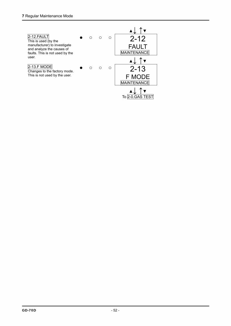
7 Regular Maintenance Mode
GD-70D - 52 -
↓ ↑ 2-12
FAULT MAINTENANCE
2-12.FAULT This is used (by the manufacturer) to investigate and analyze the causes of faults. This is not used by the user. ↓ ↑
2-13 F MODE
MAINTENANCE
2-13.F MODE Changes to the factory mode. This is not used by the user.
↓ ↑ To 2-0.GAS TEST

7 Regular Maintenance Mode
- 53 - GD-70D
<Environmental Setting 1 "2-9"> In the environmental setting 1, specify the operation setting. Environmental Setting 1
PW A1 A2 F LCD 2-9.SETTING1 Press the SET key.
2- 9 SETTING1
MAINTENANCE
↓ ↓ SET 0
INHIBIT MAINTENANCE
⇔SET OFF
INHIBIT MAINTENANCE
↓↑
ON INHIBIT
MAINTENANCE INHIBIT
SET 0.INHIBIT Set the inhibit. Select either ON/OFF, and then press the SET key to confirm the selection. When ON is selected, the message INHIBIT is displayed on the LCD. As a result, an alarm is not triggered to external circuits even though the detector is in the detection mode.
| ↑ | |
↓ |
SET 1 ALM P
MAINTENANCE
⇔SET
Alarm Value Setting ⇒P54
SET 1.ALM P Set the alarm value.
↓ ↑ SET 2
ALM DLY MAINTENANCE
⇔SET 2
ALM DLY MAINTENANCE
SET 2.ALM DLY Set the alarm delay time. Select the number (second) by pressing the or key, and then press the SET key to confirm the value. ↓ ↑
SET 3 MAINTE
MAINTENANCE
⇔SET -----
MAINTE MAINTENANCE
SET 3. MAINTE This is used to stop only the pump for replacing the pump or for another purpose. Press the SET key to stop the pump. Press the SET key again to restart the pump, which returns to the original state. (You can also press the MODE key to cancel this menu and restart the pump.)
| ↑ | |
↓ |
Pump Stop (Drive Sound Stop)
SET 4 F TEST
MAINTENANCE
⇔SET
Fault Alarm Test ⇒P54 SET 4.F TEST
Perform a fault alarm test.
↓ ↑
To SET 0.INHIBIT Setting

7 Regular Maintenance Mode
GD-70D - 54 -
<Alarm Value Setting "2-9" - "SET 1"> Alarm Value Setting
PW A1 A2 F LCD SET 1.ALM P Press the SET key.
SET 1 ALM P
MAINTENANCE
↓ ↓ First Alarm Value Setting Select the number by pressing the or key, and then press the SET key to confirm the value. (Press the MODE key to skip this menu.)
5.0ppm AL 1
MAINTENANCE
↓ ↓ Second Alarm Value Setting Select the number by pressing the or key, and then press the SET key to confirm the value. (Press the MODE key to skip this menu.)
10.0ppm AL 2
MAINTENANCE
↓ Return to
SET 1.ALM P
<Fault Alarm Test "2-9" - "SET 4">
PW A1 A2 F LCD SET 4.F TEST Press the SET key.
SET 4 F TEST
MAINTENANCE
↓ ↓
OFF F TEST
MAINTENANCE
↓ ↑
Fault Test ON/OFF Select either ON/OFF. Switch ON and press the SET key to activate the fault alarm. Return to OFF and press the SET key to deactivate the fault alarm. (You can also press the MODE key to cancel this menu and go back to the original state.) ON
F TEST MAINTENANCE
WARNING Because the contact (fault) can be activated only by a fault alarm test in the maintenance mode, be careful to perform the test. The fault alarm test cannot be performed during inhibit.

7 Regular Maintenance Mode
- 55 - GD-70D
<Environmental Setting 2 "2-10"> In the environmental setting 2, specify the settings of functions. (* It is recommended that setting changes should be recorded in a log.) The environmental setting 2 includes setting menus which are usually not used. Be careful not to change these settings by mistake. Environmental Setting 2
PW A1 A2 F LCD 2-10.SETTING2 Press the SET key.
2-10 SETTING2
MAINTENANCE
↓ ↓ SET 0
ADDRESS MAINTENANCE
⇔ SET 01
ADDRESS MAINTENANCE
SET 0. ADDRESS Set the address. (NT specification) Select the number by pressing the or key, and then press the SET key to confirm the address. ↓ ↑
SET 1 DAY TIME
MAINTENANCE
⇔ SET
Date/Time Setting ⇒P60
SET 1.DAY TIME Set the date/time of the main unit.
↓ ↑ SET 2
SUPPRESSMAINTENANCE
⇔ SET 0.9ppm
SUPPRESS MAINTENANCE
SET 2.SUPPRESS Set the suppression value. Select the number by pressing the or key, and then press the SET key to confirm the value. ↓ ↑
SET 3 SUP TYPE
MAINTENANCE
⇔ SET CUT
SUP TYPEMAINTENANCE
↓↑
SLOPE SUP TYPE
MAINTENANCE
SET 3. SUP TYPE Set the suppression system. Select either CUT/SLOPE, and then press the SET key to confirm the selection. When CUT (Cut Off) is selected, values exceeding the suppression value are directly displayed. When SLOPE (Slope) is selected, values exceeding the suppression value are gently displayed.
| ↑ | |
| |
↓ |
SET 4 TEST RLY
MAINTENANCE
⇔ SET OFF
TEST RLY MAINTENANCE
↓↑
SET 4. TEST RLY Set the contact activation for an alarm test. Select either ON/OFF, and then press the SET key to confirm the selection. When ON is selected, the contact can be activated even during an alarm test.
| ↑
| |
↓ |
ON TEST RLY
MAINTENANCE
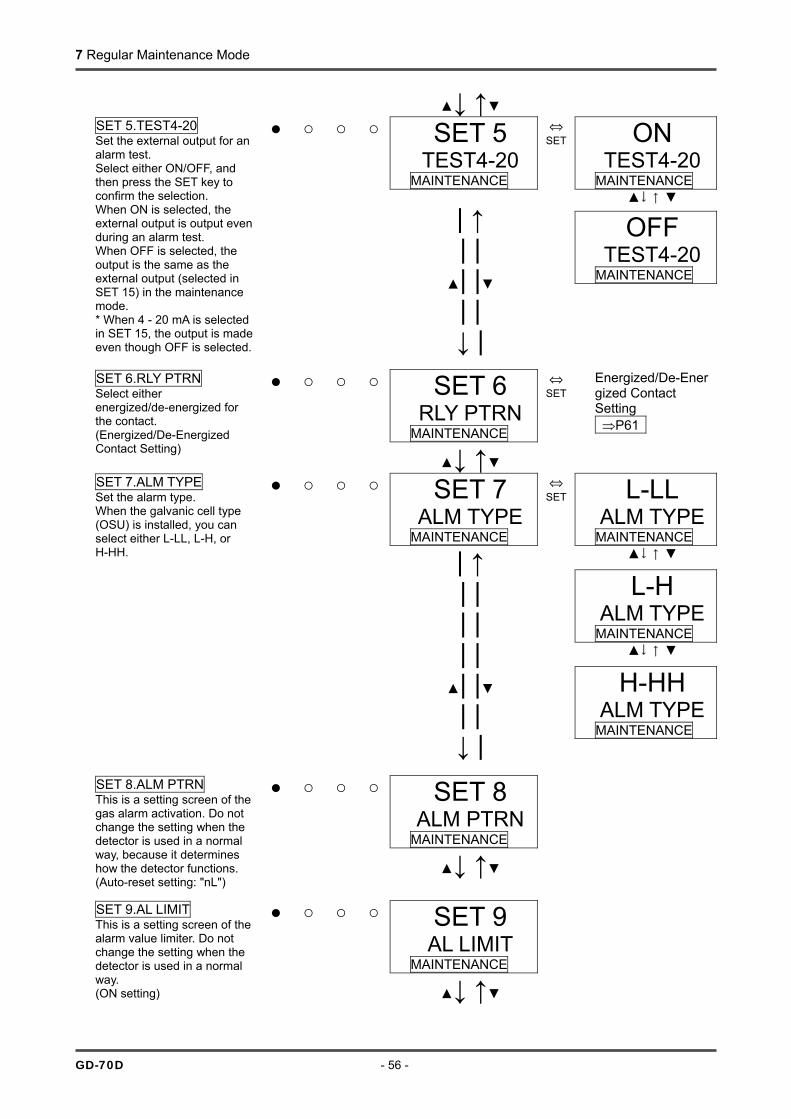
7 Regular Maintenance Mode
GD-70D - 56 -
↓ ↑
SET 5 TEST4-20
MAINTENANCE
⇔ SET ON
TEST4-20 MAINTENANCE
↓↑
OFF TEST4-20
MAINTENANCE
SET 5.TEST4-20 Set the external output for an alarm test. Select either ON/OFF, and then press the SET key to confirm the selection. When ON is selected, the external output is output even during an alarm test. When OFF is selected, the output is the same as the external output (selected in SET 15) in the maintenance mode. * When 4 - 20 mA is selected in SET 15, the output is made even though OFF is selected.
| ↑ | |
| | | |
↓ |
SET 6 RLY PTRN
MAINTENANCE
⇔ SET
Energized/De-Energized Contact Setting ⇒P61
SET 6.RLY PTRN Select either energized/de-energized for the contact. (Energized/De-Energized Contact Setting) ↓ ↑
SET 7 ALM TYPE
MAINTENANCE
⇔ SET L-LL
ALM TYPEMAINTENANCE
↓↑
L-H ALM TYPE
MAINTENANCE ↓↑
H-HH ALM TYPE
MAINTENANCE
SET 7.ALM TYPE Set the alarm type. When the galvanic cell type (OSU) is installed, you can select either L-LL, L-H, or H-HH.
| ↑ | | | | | |
| | | |
↓ |
SET 8 ALM PTRN
MAINTENANCE
↓ ↑
SET 8.ALM PTRN This is a setting screen of the gas alarm activation. Do not change the setting when the detector is used in a normal way, because it determines how the detector functions. (Auto-reset setting: "nL")
SET 9 AL LIMIT
MAINTENANCE
SET 9.AL LIMIT This is a setting screen of the alarm value limiter. Do not change the setting when the detector is used in a normal way. (ON setting)
↓ ↑
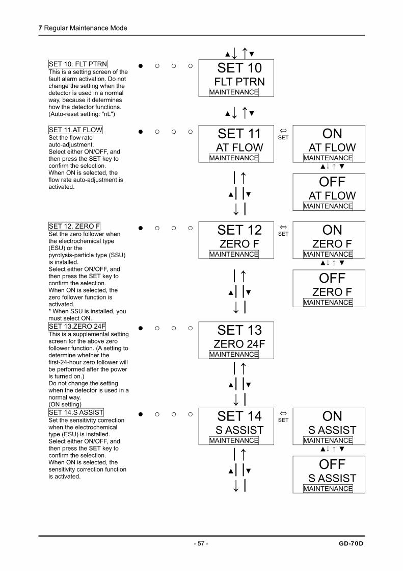
7 Regular Maintenance Mode
- 57 - GD-70D
↓ ↑
SET 10 FLT PTRN
MAINTENANCE
SET 10. FLT PTRN This is a setting screen of the fault alarm activation. Do not change the setting when the detector is used in a normal way, because it determines how the detector functions. (Auto-reset setting: "nL")
↓ ↑
SET 11 AT FLOW
MAINTENANCE
⇔ SET ON
AT FLOW MAINTENANCE
↓↑
OFF
AT FLOW MAINTENANCE
SET 11.AT FLOW Set the flow rate auto-adjustment. Select either ON/OFF, and then press the SET key to confirm the selection. When ON is selected, the flow rate auto-adjustment is activated.
| ↑ | |
↓ |
SET 12 ZERO F
MAINTENANCE
⇔ SET ON
ZERO F MAINTENANCE
↓↑
OFF ZERO F
MAINTENANCE
SET 12. ZERO F Set the zero follower when the electrochemical type (ESU) or the pyrolysis-particle type (SSU) is installed. Select either ON/OFF, and then press the SET key to confirm the selection. When ON is selected, the zero follower function is activated. * When SSU is installed, you must select ON.
| ↑ | |
↓ |
SET 13 ZERO 24F
MAINTENANCE
SET 13.ZERO 24F This is a supplemental setting screen for the above zero follower function. (A setting to determine whether the first-24-hour zero follower will be performed after the power is turned on.) Do not change the setting when the detector is used in a normal way. (ON setting)
| ↑ | |
↓ |
SET 14 S ASSIST
MAINTENANCE
⇔ SET ON
S ASSIST MAINTENANCE
↓↑
SET 14.S ASSIST Set the sensitivity correction when the electrochemical type (ESU) is installed. Select either ON/OFF, and then press the SET key to confirm the selection. When ON is selected, the sensitivity correction function is activated.
| ↑
| |
↓ |
OFF S ASSIST
MAINTENANCE

7 Regular Maintenance Mode
GD-70D - 58 -
↓ ↑
SET 15 MNT OUT
MAINTENANCE
⇔ SET 2.5mA
MNT OUT MAINTENANCE
↓↑
4.0mA MNT OUT
MAINTENANCE ↓↑
HOLD MNT OUT
MAINTENANCE ↓↑
4-20mA MNT OUT
MAINTENANCE
SET 15. MNT OUT Set the external output for the maintenance mode. Select either 2.5 mA/4.0 mA/HOLD (previous value)/4 - 20 mA (linked to display value), and then press the SET key to confirm the selection. (4 - 20 mA specification)
| ↑ | |
| | | |
| |
| | | | | |
↓ |
SET 16 MA 4-20
MAINTENANCE
⇔ SET 100%
4MA ADJ MAINTENANCE
↓
100% 20MA ADJ
MAINTENANCE
SET 16.MA 4-20 Adjust the external output (4 - 20 mA). Adjust the output (%) by pressing the or key, and then press the SET key to confirm the value. (It must be adjusted to the upper unit or the ammeter.) After adjustment of 4 mA is completed, perform the adjustment of 20 mA. (Press the MODE key to skip this menu.) (4 - 20 mA specification)
| ↑ | |
| |
| |
↓ |
SET 17 BK LIGHT
MAINTENANCE
⇔ SET ON
BK LIGHT MAINTENANCE
↓↑
SAVE BK LIGHT
MAINTENANCE
SET 17.BK LIGHT Set the backlight. Select either ON/SAVE, and then press the SET key to confirm the selection. When ON is selected, the backlight lights up continuously. When SAVE is selected, the backlight is usually turned off, but lights up only during an operation or event.
| ↑ | |
↓ |
SET 18 ETHERNETMAINTENANCE
SET 18. ETHERNET This is a setting screen of the ETHERNET setting. This is not used for the detector.
↓ ↑

7 Regular Maintenance Mode
- 59 - GD-70D
SET 19 PUMP CK
MAINTENANCE
⇔ SET ON
PUMP CK MAINTENANCE
↓↑
OFF PUMP CK
MAINTENANCE
SET 19.PUMP CK Set the pump drive level diagnosis. Select either ON/OFF, and then press the SET key to confirm the selection. When ON is selected, the message "FLOW" is displayed if the flow rate is sufficient even though the pump drive level is low. (A function to check the conditions for applying pressure, etc.)
| ↑ | |
↓ |
To SET 0. ADDRESS
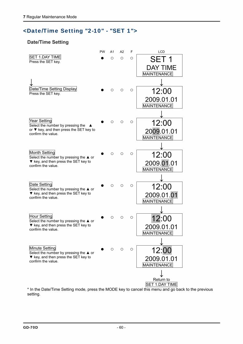
7 Regular Maintenance Mode
GD-70D - 60 -
<Date/Time Setting "2-10" - "SET 1"> Date/Time Setting PW A1 A2 F LCD SET 1.DAY TIME Press the SET key.
SET 1 DAY TIME
MAINTENANCE
↓ ↓ Date/Time Setting Display Press the SET key.
12:00 2009.01.01
MAINTENANCE
↓ Year Setting Select the number by pressing the or key, and then press the SET key to confirm the value.
12:00 2009.01.01
MAINTENANCE
↓ Month Setting Select the number by pressing the or key, and then press the SET key to confirm the value.
12:00 2009.01.01
MAINTENANCE
↓ Date Setting Select the number by pressing the or key, and then press the SET key to confirm the value.
12:00 2009.01.01
MAINTENANCE
↓ Hour Setting Select the number by pressing the or key, and then press the SET key to confirm the value.
12:00 2009.01.01
MAINTENANCE
↓ Minute Setting Select the number by pressing the or key, and then press the SET key to confirm the value.
12:00 2009.01.01
MAINTENANCE
↓ Return to
SET 1.DAY TIME
* In the Date/Time Setting mode, press the MODE key to cancel this menu and go back to the previous setting.
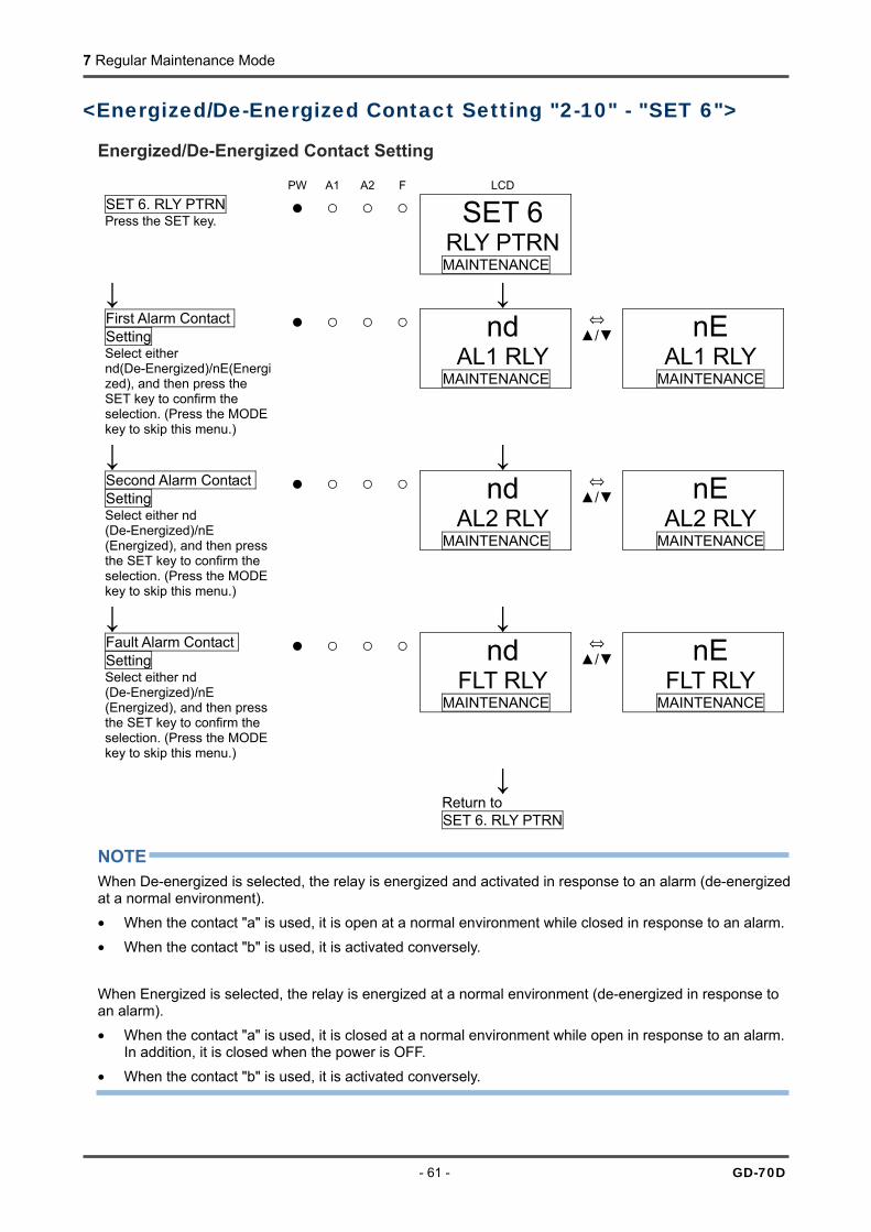
7 Regular Maintenance Mode
- 61 - GD-70D
<Energized/De-Energized Contact Setting "2-10" - "SET 6"> Energized/De-Energized Contact Setting PW A1 A2 F LCD SET 6. RLY PTRN Press the SET key.
SET 6 RLY PTRNMAINTENANCE
↓ ↓ nd
AL1 RLY MAINTENANCE
⇔ / nE
AL1 RLY MAINTENANCE
First Alarm Contact Setting Select either nd(De-Energized)/nE(Energized), and then press the SET key to confirm the selection. (Press the MODE key to skip this menu.)
↓ ↓ nd
AL2 RLY MAINTENANCE
⇔ / nE
AL2 RLY MAINTENANCE
Second Alarm Contact Setting Select either nd (De-Energized)/nE (Energized), and then press the SET key to confirm the selection. (Press the MODE key to skip this menu.)
↓ ↓ nd
FLT RLY MAINTENANCE
⇔ / nE
FLT RLY MAINTENANCE
Fault Alarm Contact Setting Select either nd (De-Energized)/nE (Energized), and then press the SET key to confirm the selection. (Press the MODE key to skip this menu.)
↓ Return to
SET 6. RLY PTRN
NOTE When De-energized is selected, the relay is energized and activated in response to an alarm (de-energized at a normal environment). • When the contact "a" is used, it is open at a normal environment while closed in response to an alarm.
• When the contact "b" is used, it is activated conversely. When Energized is selected, the relay is energized at a normal environment (de-energized in response to an alarm).
• When the contact "a" is used, it is closed at a normal environment while open in response to an alarm. In addition, it is closed when the power is OFF.
• When the contact "b" is used, it is activated conversely.
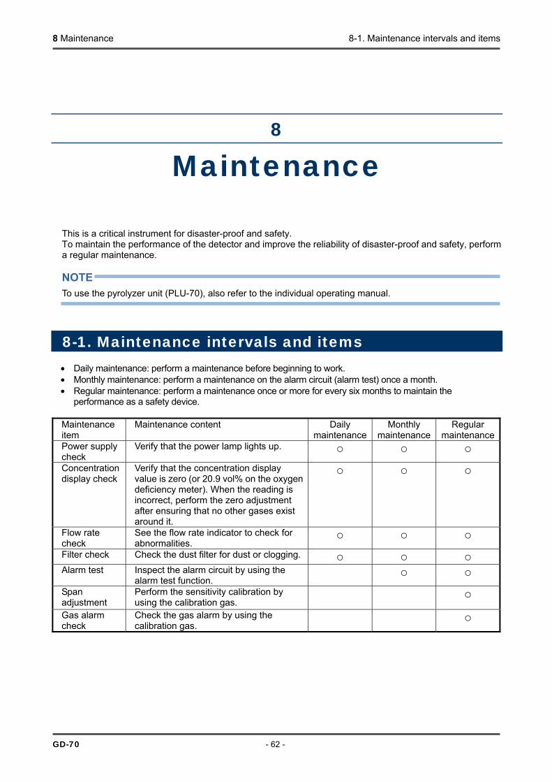
8 Maintenance 8-1. Maintenance intervals and items
GD-70 - 62 -
8
Maintenance This is a critical instrument for disaster-proof and safety. To maintain the performance of the detector and improve the reliability of disaster-proof and safety, perform a regular maintenance. NOTE To use the pyrolyzer unit (PLU-70), also refer to the individual operating manual.
8-1. Maintenance intervals and items • Daily maintenance: perform a maintenance before beginning to work. • Monthly maintenance: perform a maintenance on the alarm circuit (alarm test) once a month. • Regular maintenance: perform a maintenance once or more for every six months to maintain the
performance as a safety device. Maintenance item
Maintenance content Daily maintenance
Monthly maintenance
Regular maintenance
Power supply check
Verify that the power lamp lights up. Concentration display check
Verify that the concentration display value is zero (or 20.9 vol% on the oxygen deficiency meter). When the reading is incorrect, perform the zero adjustment after ensuring that no other gases exist around it.
Flow rate check
See the flow rate indicator to check for abnormalities.
Filter check Check the dust filter for dust or clogging. Alarm test Inspect the alarm circuit by using the
alarm test function.
Span adjustment
Perform the sensitivity calibration by using the calibration gas.
Gas alarm check
Check the gas alarm by using the calibration gas.
8 Maintenance 8-1. Maintenance intervals and items
- 63 - GD-70D
<About Maintenance Services>
• We provide services on regular maintenance including span adjustment, adjustment and maintenance. To make the calibration gas, dedicated tools, such as a gas cylinder of the specified concentration and gas sampling bag must be used. Our qualified service engineers have expertise and knowledge on the dedicated tools used for services, along with other products. To maintain the safety operation of the detector, please use our maintenance service.
• The followings are typical maintenance services. Please contact our sales department for more information. Main Services
Power Supply Check
: Checks the power supply voltage. Verifies that the power lamp lights up. (Verifies that relevant points can be identified on the system.) (When a UPS (uninterruptible power system) is used, checks the operation with the UPS (uninterruptible power system).)
Concentration Display Check
: Verifies that the concentration display value is zero (or 20.9 vol% on the oxygen deficiency meter) by using the zero gas. Performs the zero adjustment (AIR adjustment) if the reading is incorrect.
Flow Rate Check : Checks the flow rate indicator to find abnormalities. Checks the flow rate by using an external flow meter to verify the correctness of the flow rate indicator on the detector. If the flow rate is incorrect, performs the flow rate adjustment.
Filter Check : Checks the dust filter for dust or clogging. Replaces a dirty or clogged dust filter. Inspects the alarm circuit by using the alarm test function. • Checks the alarm lamps. (Checks each activation of ALM1 and ALM2.)
Alarm Test :
• Checks the external alarm. (Checks the activation of the external alarm, such as a buzzer.) Span adjustment : Performs the sensitivity calibration by using the calibration gas.
Checks the gas alarm by using the calibration gas. • Checks the alarm. (Checks the alarm activation when the alarm setpoint is reached.) • Checks the delay time. (Checks time to delay until the alarm is triggered.) • Check the alarm lamps. (Check each activation of ALM1 and ALM2.)
Gas Alarm Check
:
• Check the external alarm. (Check the activation of external alarms, such as a buzzer and reset signal.)
Cleaning and repair of the detector (visual diagnosis)
: If you find dust or damage on surface, cover, or internal parts of the detector, clean and repair such parts of the detector. Replace parts which are cracked or damaged.
Detector Operation Check
: Uses the keys to check the operation of functions and parameters.
Replacement of Worn Parts
: Replaces worn parts, such as a sensor, filter and pump.

8 Maintenance 8-2. Gas calibration method
GD-70D - 64 -
8-2. Gas calibration method Perform a gas calibration in each mode (zero adjustment mode and span adjustment mode) using the calibration gas. • Zero adjustment gas (collected in a gas sampling bag) • Span adjustment gas (collected in a gas sampling bag) • Gas sampling bag for exhaust
<Zero Adjustment "2-1">
This is used to perform the zero adjustment. NOTE Before starting the zero adjustment, let the detector suck the zero adjustment gas and wait until the indicator is stabilized.
WARNING When the zero adjustment is performed in the atmosphere, check the atmosphere for freshness before beginning the adjustment. If other gases exist, the adjustment cannot be performed properly, thus leading to dangers when the gas leaks.
Exhaust gas
GAS IN GAS OUTCalibration gas
WARNING After the adjustment is completed, do not forget to press the MODE key to return to the detection mode.
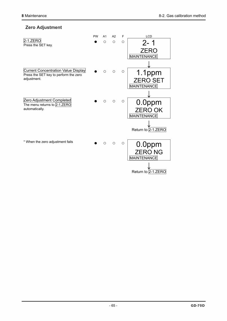
8 Maintenance 8-2. Gas calibration method
- 65 - GD-70D
Zero Adjustment
PW A1 A2 F LCD 2-1.ZERO Press the SET key.
2- 1 ZERO
MAINTENANCE
↓ Current Concentration Value Display Press the SET key to perform the zero adjustment.
1.1ppm ZERO SET
MAINTENANCE
↓ Zero Adjustment Completed The menu returns to 2-1.ZERO automatically.
0.0ppm ZERO OK
MAINTENANCE
↓ Return to 2-1.ZERO * When the zero adjustment fails 0.0ppm
ZERO NG MAINTENANCE
↓ Return to 2-1.ZERO

8 Maintenance 8-2. Gas calibration method
GD-70D - 66 -
<Span Adjustment "2-2">
This is used to perform the span adjustment. For the oxygen deficiency alarm specification (OSU - 0 - 25 vol%), this is the same as "1-1". Span Adjustment Display
PW A1 A2 F LCD 2-2.SPAN Press the SET key.
2-2 SPAN
MAINTENANCE
↓ ↓ Gas Introduction Introduce a gas, and then press the SET key when the reading is stabilized. * In case of less than 10%FS, this is not switched to the next menu.
2.0ppm SPAN GAS
MAINTENANCE
↓ ↓ 8.0ppm
SPAN VAL MAINTENANCE
Span Adjustment Because the reading will be fixed, select the introduced gas concentration by pressing the or key. Select the number, and then press the SET key. (20.9 vol% in the oxygen deficiency alarm specification)
↓ ↓ Span Adjustment Completed 8.0ppm
SPAN OK MAINTENANCE
↓ ↓ Adjustment result record To record the adjustment result, press the SET key. (Press the MODE key to cancel this menu.)
8.0ppm SPAN Y/N
MAINTENANCE
↓ ↓ Adjustment Completed The menu returns to 2-2.SPAN automatically.
8.0ppm SPAN END
MAINTENANCE
↓ Return to 2-2.SPAN
* When the span adjustment fails 8.0ppm SPAN NG
MAINTENANCE
↓ Return to 2-2.SPAN
CAUTIONDo not press the SET key before the reading is stabilized.
CAUTION Exhaust gas must be collected in the exhaust bag or discharged through the exhaust line.

8 Maintenance 8-3. Other adjustments/Cleaning method
- 67 - GD-70D
8-3. Other adjustments/Cleaning method
<Flow Rate Manual Adjustment "2-6" and Flow Rate Default Set "2-5">
The flow rate of the detector is automatically adjusted to 0.5 L/min. Turning off the auto-adjustment function enables the manual adjustment. (See 2-10 - SET-11) The manual flow rate adjustment can be performed in the regular maintenance mode "2-6.FLOW".
PW A1 A2 F LCD 2-6.FLOW Press the SET key.
2-6 FLOW
MAINTENANCE
↓ ↓ 50 %
0.50 L/M MAINTENANCE
Flow Rate Adjustment As the output is increased or decreased by pressing the or key, the flow rate changes accordingly. Adjust the flow rate to 0.5 L/min, and then press the SET key. (Press the MODE key to cancel this menu.) Regardless of the flow rate auto-adjustment or manual-adjustment, when the reading on the flow rate indicator is incorrect (due to aging degradation, improper flow rate default set, or other reasons), it must be set to provide the right flow rate. To set the Flow Rate Indicator, prepare and connect a flow meter (which indicates 0.5 L/min precisely), and perform the default set with the flow meter while it is indicating 0.5 L/min in the regular maintenance mode "2-5.DEF FLOW".
PW A1 A2 F LCD
2-5.DEF FLOW Press the SET key.
2- 5 DEF FLOW
MAINTENANCE
↓ ↓ 1000
DEF FLOW MAINTENANCE
Flow Rate Adjustment/Default Set Adjust the flow rate by pressing the or key until the connected flow meter indicates 0.5 L/min ± 10%, and then press the SET key. (Press the MODE key to cancel this menu.)
CAUTION Perform the flow rate default set after verifying that the suction volume is 0.5 L/min by using a flow meter.
WARNING After the adjustment is completed, do not forget to press the MODE key to return to the detection mode.

8 Maintenance 8-4. How to replace parts
GD-70D - 68 -
<Cleaning of Detector>
Clean the detector if it becomes extremely dirty. The detector must be turned off while cleaning it. Use a waste cloth to remove dust. Do not use water or organic solvent for cleaning because they cause malfunctions. Because an extremely large amount of dust inside the tube may disturb the gas detection, it must be cleaned with dry AIR, etc.
8-4. How to replace parts
<Replacement of Consumables>
Sensor Unit Replacement The sensor unit can be replaced in a single step as shown in the figure. When attaching the sensor unit to the main unit, thrust it onto the main unit and make sure that the sensor unit is securely fixed, otherwise it might come off. After replacing the sensor unit, close the front cover. Be sure to check the click of the front cover to fix it properly, otherwise it might open again.
External Dust Filter Replacement Because the external dust filter may gradually get dirty or clogged over the time, it must be replaced regarding the operating conditions. Check the external dust filter, and then replace it as necessary.
CAUTION • Turn OFF the power when the sensor unit is replaced. • After the sensor unit is replaced, always perform a gas
calibration (zero adjustment and span adjustment).

8 Maintenance 8-4. How to replace parts
- 69 - GD-70D
<Replacement of Regular Replacement Parts>
List of recommended regular replacement parts
No. Item Maintenance intervals
Replacement intervals
Quantity (pieces/unit)
1 Pump unit 0.5 year 1 - 2 years 1 2 Flow sensor 1 year 5 year 1
NOTE The above replacement intervals are recommendation only. The intervals may change depending on the operating conditions. These intervals do not mean the warranty periods either. The result of the regular maintenance may determine when to replace the parts. Replacement of Pump Unit The pump unit can be replaced in a single step as shown in the figure. When attaching the pump unit to the main unit, position the grooves of the pump unit at the rails of the main unit and push the pump unit. Do not push the center diaphragm. Push the part labeled "PULL". And as the connecting point (flow path) of the pump unit is greased, be sure to check for any dust. Replacement of Flow Sensor After the flow sensor is replaced, the operation must be checked by a qualified service engineer. For the stable operation of the detector and safety, ask a qualified service engineer to take care of replacement of the parts whose operation must be checked. Please contact our sales department.
Groove Rail
Connecting point (flow path)
Do not push here.
"PULL"
×

8 Maintenance 8-5. Procedures to store the detector or leave it for a long time
GD-70D - 70 -
8-5. Procedures to store the detector or leave it for a long time
The detector must be stored under the following environmental conditions. • In a dark place under the normal temperature and humidity away from direct sunlight • In a place where gases, solvents or vapors are not present
CAUTION When you use a relocated or stopped/stored detector again, do not forget to perform a gas calibration. For information on readjustment including gas calibration, please contact our sales department.
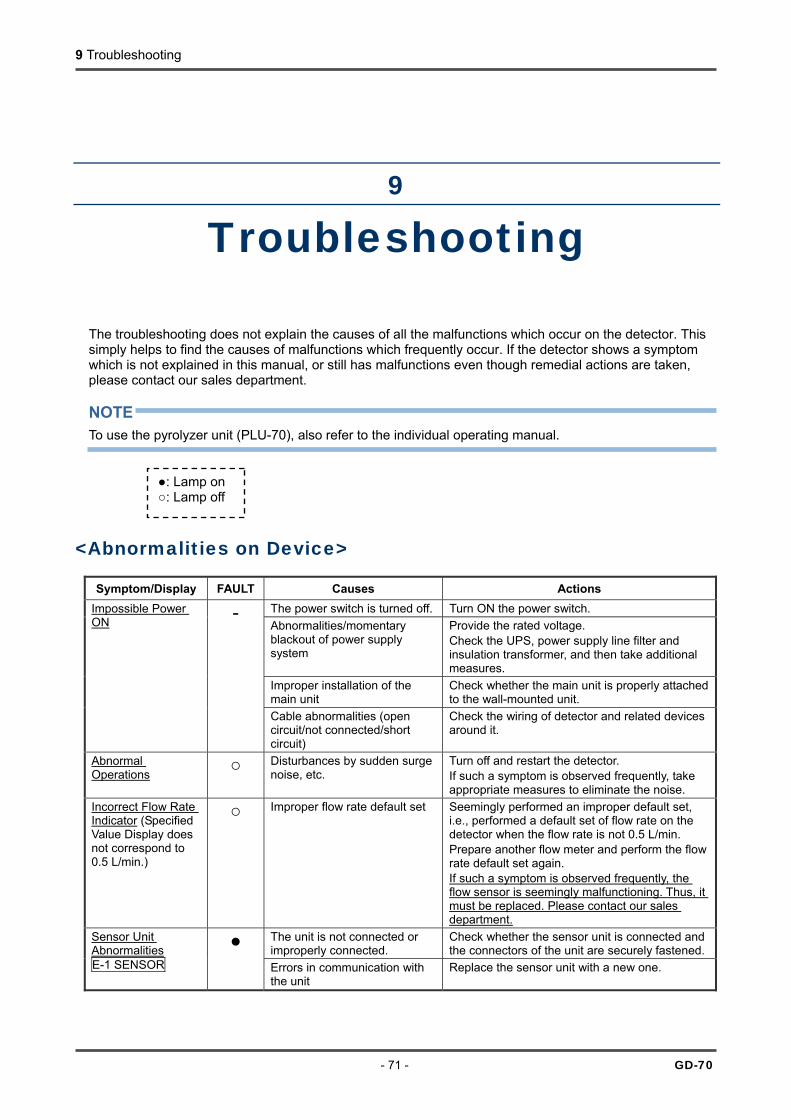
9 Troubleshooting
- 71 - GD-70
9
Troubleshooting The troubleshooting does not explain the causes of all the malfunctions which occur on the detector. This simply helps to find the causes of malfunctions which frequently occur. If the detector shows a symptom which is not explained in this manual, or still has malfunctions even though remedial actions are taken, please contact our sales department. NOTE To use the pyrolyzer unit (PLU-70), also refer to the individual operating manual.
<Abnormalities on Device>
Symptom/Display FAULT Causes Actions The power switch is turned off. Turn ON the power switch. Abnormalities/momentary blackout of power supply system
Provide the rated voltage. Check the UPS, power supply line filter and insulation transformer, and then take additional measures.
Improper installation of the main unit
Check whether the main unit is properly attached to the wall-mounted unit.
Impossible Power ON -
Cable abnormalities (open circuit/not connected/short circuit)
Check the wiring of detector and related devices around it.
Abnormal Operations Disturbances by sudden surge
noise, etc. Turn off and restart the detector. If such a symptom is observed frequently, take appropriate measures to eliminate the noise.
Incorrect Flow Rate Indicator (Specified Value Display does not correspond to 0.5 L/min.)
Improper flow rate default set Seemingly performed an improper default set, i.e., performed a default set of flow rate on the detector when the flow rate is not 0.5 L/min. Prepare another flow meter and perform the flow rate default set again. If such a symptom is observed frequently, the flow sensor is seemingly malfunctioning. Thus, it must be replaced. Please contact our sales department.
The unit is not connected or improperly connected.
Check whether the sensor unit is connected and the connectors of the unit are securely fastened.
Sensor Unit Abnormalities E-1 SENSOR
Errors in communication with the unit
Replace the sensor unit with a new one.
: Lamp on : Lamp off
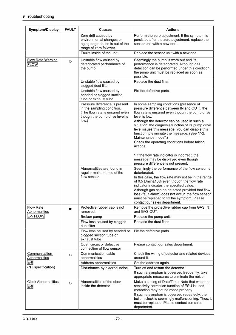
9 Troubleshooting
GD-70D - 72 -
Symptom/Display FAULT Causes Actions Zero drift caused by environmental changes or aging degradation is out of the range of zero follower.
Perform the zero adjustment. If the symptom is persisted after the zero adjustment, replace the sensor unit with a new one.
Faults inside of the unit Replace the sensor unit with a new one.
Unstable flow caused by deteriorated performance of the pump
Seemingly the pump is worn out and its performance is deteriorated. Although gas detection can be performed under this condition, the pump unit must be replaced as soon as possible.
Unstable flow caused by clogged dust filter
Replace the dust filter.
Unstable flow caused by bended or clogged suction tube or exhaust tube
Fix the defective parts.
Pressure difference is present in the sampling condition. (The flow rate is ensured even though the pump drive level is low.)
In some sampling conditions (presence of pressure difference between IN and OUT), the flow rate is ensured even though the pump drive level is low. Although the detector can be used in such a situation, the diagnosis function of its pump drive level issues this message. You can disable this function to eliminate the message. (See "7-2. Maintenance mode".) Check the operating conditions before taking actions. * If the flow rate indicator is incorrect, the message may be displayed even though pressure difference is not present.
Flow Rate Warning FLOW
Abnormalities are found in regular maintenance of the flow sensor.
Seemingly the performance of the flow sensor is deteriorated. In this case, the flow rate may not be in the range of 0.5 L/min±10% even though the flow rate indicator indicates the specified value. Although gas can be detected provided that flow loss (fault alarm) does not occur, the flow sensor must be replaced to fix the symptom. Please contact our sales department.
Protective rubber cap is not removed.
Remove the protective rubber cap from GAS IN and GAS OUT.
Broken pump Replace the pump unit. Flow loss caused by clogged dust filter
Replace the dust filter.
Flow loss caused by bended or clogged suction tube or exhaust tube
Fix the defective parts.
Flow Rate Abnormalities E-5 FLOW
Open circuit or defective connection of flow sensor
Please contact our sales department.
Communication cable abnormalities
Check the wiring of detector and related devices around it.
Address abnormalities Set the address again.
Communication Abnormalities E-6 (NT specification)
Disturbance by external noise Turn off and restart the detector. If such a symptom is observed frequently, take appropriate measures to eliminate the noise.
Clock Abnormalities E-9
Abnormalities of the clock inside the detector
Make a setting of Date/Time. Note that when the sensitivity correction function of ESU is used, correction may not be made properly. If such a symptom is observed repeatedly, the built-in clock is seemingly malfunctioning. Thus, it must be replaced. Please contact our sales department.
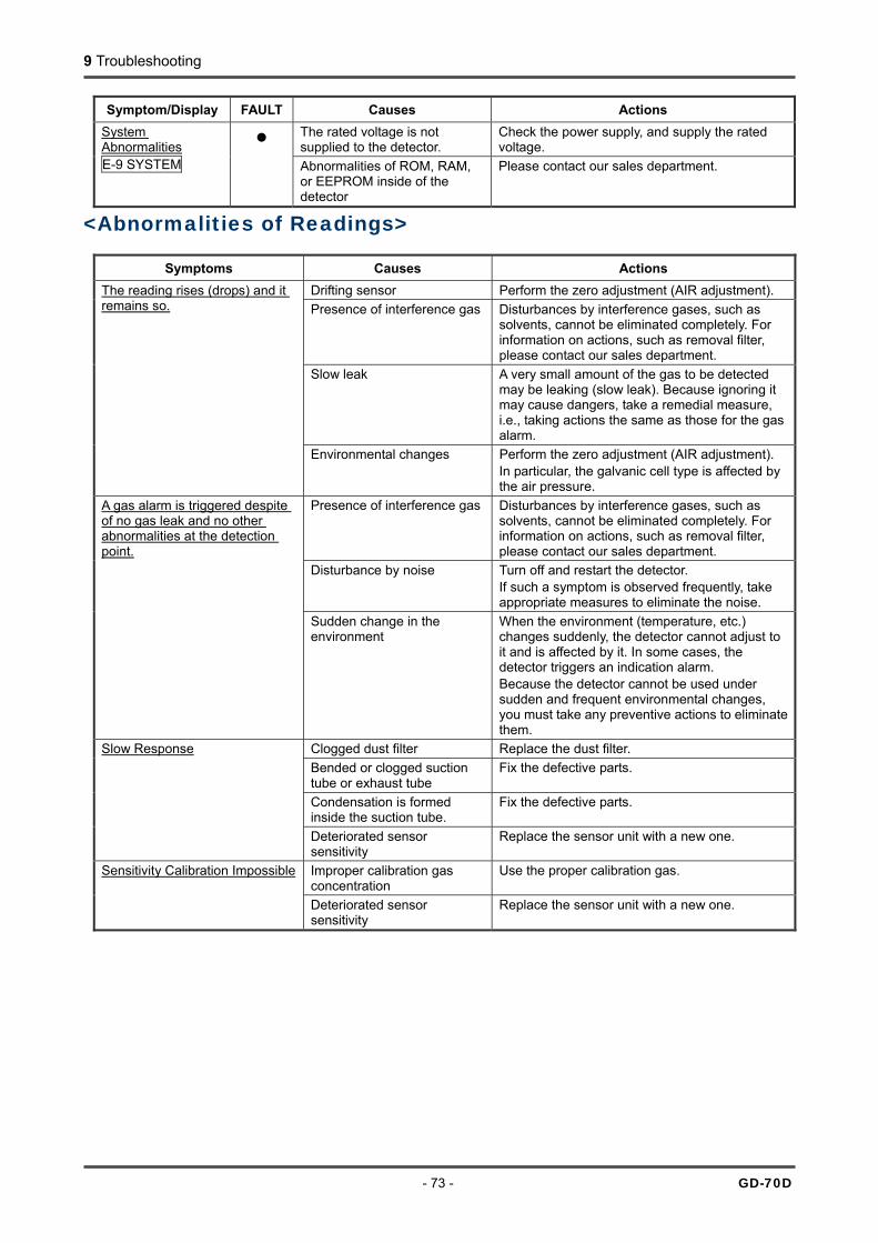
9 Troubleshooting
- 73 - GD-70D
Symptom/Display FAULT Causes Actions The rated voltage is not supplied to the detector.
Check the power supply, and supply the rated voltage.
System Abnormalities E-9 SYSTEM
Abnormalities of ROM, RAM, or EEPROM inside of the detector
Please contact our sales department.
<Abnormalities of Readings>
Symptoms Causes Actions Drifting sensor Perform the zero adjustment (AIR adjustment). Presence of interference gas Disturbances by interference gases, such as
solvents, cannot be eliminated completely. For information on actions, such as removal filter, please contact our sales department.
Slow leak A very small amount of the gas to be detected may be leaking (slow leak). Because ignoring it may cause dangers, take a remedial measure, i.e., taking actions the same as those for the gas alarm.
The reading rises (drops) and it remains so.
Environmental changes Perform the zero adjustment (AIR adjustment). In particular, the galvanic cell type is affected by the air pressure.
Presence of interference gas Disturbances by interference gases, such as solvents, cannot be eliminated completely. For information on actions, such as removal filter, please contact our sales department.
Disturbance by noise Turn off and restart the detector. If such a symptom is observed frequently, take appropriate measures to eliminate the noise.
A gas alarm is triggered despite of no gas leak and no other abnormalities at the detection point.
Sudden change in the environment
When the environment (temperature, etc.) changes suddenly, the detector cannot adjust to it and is affected by it. In some cases, the detector triggers an indication alarm. Because the detector cannot be used under sudden and frequent environmental changes, you must take any preventive actions to eliminate them.
Clogged dust filter Replace the dust filter. Bended or clogged suction tube or exhaust tube
Fix the defective parts.
Condensation is formed inside the suction tube.
Fix the defective parts.
Slow Response
Deteriorated sensor sensitivity
Replace the sensor unit with a new one.
Improper calibration gas concentration
Use the proper calibration gas. Sensitivity Calibration Impossible
Deteriorated sensor sensitivity
Replace the sensor unit with a new one.
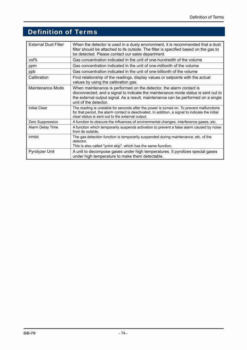
Definition of Terms
GD-70 - 74 -
Definition of Terms External Dust Filter When the detector is used in a dusty environment, it is recommended that a dust
filter should be attached to its outside. The filter is specified based on the gas to be detected. Please contact our sales department.
vol% Gas concentration indicated in the unit of one-hundredth of the volume ppm Gas concentration indicated in the unit of one-millionth of the volume ppb Gas concentration indicated in the unit of one-billionth of the volume Calibration Find relationship of the readings, display values or setpoints with the actual
values by using the calibration gas. Maintenance Mode When maintenance is performed on the detector, the alarm contact is
disconnected, and a signal to indicate the maintenance mode status is sent out to the external output signal. As a result, maintenance can be performed on a single unit of the detector.
Initial Clear The reading is unstable for seconds after the power is turned on. To prevent malfunctions for that period, the alarm contact is deactivated. In addition, a signal to indicate the initial clear status is sent out to the external output.
Zero Suppression A function to obscure the influences of environmental changes, interference gases, etc. Alarm Delay Time A function which temporarily suspends activation to prevent a false alarm caused by noise
from its outside. Inhibit The gas detection function is temporarily suspended during maintenance, etc. of the
detector. This is also called "point skip", which has the same function.
Pyrolyzer Unit A unit to decompose gases under high temperatures. It pyrolizes special gases under high temperature to make them detectable.

Detection principle
- 75 - GD-70
Detection principle
<Electrochemical Type>
The electric potential between the working electrode and reference electrode is kept at a certain level by a potentiostat circuit. The gas to be detected is electrolyzed directly at the working electrode. Because the electric current generated there is proportional to the gas concentration, the gas concentration can be known by measuring the electric current flown between the working electrode and the opposite electrode.
Special precautions for this principle 1. The detector is interfered by gases other than the gas to be detected, solvents, vapors, etc.
Please note that the alarm can be triggered by interference. In addition, it may be fluctuated by environmental (temperature, humidity, etc.) changes in the installation site.
2. The alarm must be set within a range where the performance of the detector can be ensured. In facilities compliant with the High Pressure Gas Safety Act, an alarm setting below our standard alarm setpoint (threshold limit value) may trigger a false alarm.
3. This is a safety device, not a control device. The alarm contact output of the detector must be used for an external alarm lamp/buzzer, while the alarm signal output must be used for an indicator or external recorder. If these outputs are used to control other devices, we shall not be responsible for any malfunctions.
4. Because the contact point of the gas detector sensor is made of porous polymeric membrane, the water repellency of the membrane is deteriorated by solvents, thus causing an electrolyte leak from its inside. Do not use solvents near the detector. If you must use a solvent for unavoidable reasons, attach the recommended filter to the inlet of the gas detector while using the solvent and for one hour after that.
5. For maintenance of the detector, it must go through a regular maintenance, including replacement and adjustment of the regular replacement parts as specified in the operating manual. In addition, because this is a safety device, it is recommended that a regular maintenance and gas calibration are performed for every six months in accordance with the regulations.
Electrolyte
R (Resistance)
Reference electrode
Opposite electrode
Working electrode
Gas permeable membrane
Gas in
Gas out
Structure diagram
Potentiostat circuit

Detection principle
GD-70D - 76 -
<Pyrolysis-Particle Type>
When the gas to be detected is heated to several hundred degrees, particulate solid oxides are formed. This is a sensor to detect particles formed in such a way by using the α ray absorbing method. Structure This unit consists of a pyrolyzer which heats gas to several hundred degrees and a particle detector which detect oxides. The pyrolyzer has a quartz pipe at its center covered with a heating element and a heat insulator around it. The particle detector consists of the measurement box in which α ray always generates ion current and the compensation box which has the identical structure (gas is not introduced). Principle When most of organic metal (MO) gas, such as TEOS, are heated, particulate oxides are formed. Sample gas which is decomposed to oxides in the Pyrolyzer is introduced into the particle detector. Inside of the measurement box of the particle detector, the α ray radiation source *1 ionizes the air and generates ion current. Ion current is also generated in the compensation box, and its ratio is maintained at a certain level in both the measurement box and the compensation box when no gas is present. When particles are introduced into the measurement box, the particles adsorb ions, thus reducing the ion current. Its ratio to the compensation box changes, which can be obtained from the detector. * 1: Am-241 37kBq Special precautions for this principle 1. The detector is interfered by gases other than the gas to be detected, and vapors.
Please note that the alarm can be triggered by interference. In addition, it may be fluctuated by environmental (temperature, humidity, etc.) changes in the installation site.
2. The alarm must be set within a range where the performance of the detector can be ensured. In facilities compliant with the High Pressure Gas Safety Act, an alarm setting below our standard alarm setpoint may trigger a false alarm.
3. This is a safety device, not a control device. The alarm contact output of the detector must be used for an external alarm lamp/buzzer, while the alarm signal output must be used for an indicator or external recorder. If these outputs are used to control other devices, we shall not be responsible for any malfunctions.
4. The gas detection sensor unit attached to the detector contains a small amount of radioactive materials. Do not disassemble it, or dispose of it like other wastes. (For information on how to handle the sensor, see the "Safety Manual".)
5. For maintenance of the detector, it must go through a regular maintenance, including replacement and adjustment of the regular replacement parts as specified in the operating manual. In addition, because this is a safety device, it is recommended that a regular maintenance and gas calibration are performed for every six months in accordance with the regulations.
Heat insulatorHeater
Gas
Quartz pipe
(Pyrolyzer)
High input impedance amplifier
V+
V-
Sample gasMeasurement box
Insulator
Output
Collector electrode Compensation box
(Particle detector)
Am-241
Am-241
A

Detection principle
- 77 - GD-70D
The detector has the pyrolysis-particle type sensor, which is a radioisotope-equipped device. It is examined in accordance with the regulations on "Article 12 - 3 of Act on Prevention of Radiation Disease Due to Radioisotopes, etc." (Nuclear Safety Technology Center, a certification and registration body), and certified as a specified designing certification device, which is regarded as a device causing little radiation damage. (Certificate Number: 091 ) No registrations have to be made to use a gas detector with the pyrolysis-particle type sensor installed (as far as it is used in accordance with this operating manual). When the pyrolysis-particle type sensor is used as a single device, observe the certification conditions specified in the "Safety Manual". <Safety Manual> No.4019 4059 2 The pyrolysis-particle type sensor (SS-1923/1924 and SS-1925 Note1)) is a radioisotope-equipped device which uses radioisotope 37 kBq 241-Am. This pyrolysis-particle type sensor is certified as a specified designing certification device by Nuclear Safety Technology Center, a certification and registration body causing little radiation damage. (SS-1923/1924 : Certificate Number 027, SS-1925 : Certificate Number 091) When the sensor is used within Japan, no registrations have to be made Note2). However, because the regulations are applied to the sensor, it must be used in accordance with the following certification conditions Note3). • Do not disassemble the sensor Note4). • The sensor must be installed in our product when it is used. Do not remove it from the product if not
necessary. • When the sensor is detached from the product and is stored, you must introduce measures to prevent
it from being taken out freely, i.e., putting it into the dedicated box we specify, and keeping it in a locked room.
• When the sensor is no longer needed, do not dispose of it, but return it to us. • The sensor must be handled as a L-type package. It must be put into the dedicated box we specify or
integrated into our product which is labeled as a "Radioactive L-type package" when it is transported. • When the sensor is transported, it must be handled by a transportation company which can handle
L-type packages Note5). Note 1) SS-1925 indicates the sensor installed in the pyrolysis-particle type sensor unit SSU-1925. Note 2) When the sensor is used outside of Japan, observe the regulations of the respective
country. Note 3) When the sensor is used in a way not in accordance with the certification conditions, a
usage registration must be made to the Minister of Education, Culture, Sports, Science and Technology. If you find the sensor which is not controlled properly, please let us know.
Note 4) Do not disassemble the pyrolysis-particle type sensor unit SSU-1925 in which SS-1925 is installed.
Note 5) L-type packages can be handled by us and service companies we specify.
Web site on the designing certification: http://www.mext.go.jp/ 2-7-6 Azusawa Itabashi-ku Tokyo, 174-8744 Japan TEL 03-3966-1112 RIKEN KEIKI CO., LTD.

Detection principle
GD-70D - 78 -
Safety of the radioisotope 241Am (37 KBq) used in the pyrolysis-particle type sensor The pyrolysis-particle type sensor installed in the gas detector uses the radioisotope 241Am radiation source (18.5 KBq x 2 = 37 KBq). A specified designing certification device must satisfy the specified threshold for "1 cm dose equivalent rate at a point 10 cm away from the surface of the device" as a certificate condition, which is the following value (tolerable amount).
Tolerable amount 1 cm dose equivalent rate at a point 10 cm away from the surface of the device
1µSv•h-1
This detector which uses radioisotope 241 Am radiation source (18.5 KBq x 2 = 37 KBq) has the following 1 cm dose equivalent rate at a point 10 cm away from its surface, meaning that it completely satisfies the certification condition.
1 cm dose equivalent rate at a point 10 cm away from the surface of the sensor (calculated value)
cmrQD 12 Γ⋅= ( ) 019.000524.0
1.0105.182
2
3
=⋅××=−
[µSv•h-1 ]
Q : Amount of radioisotope 2 x 18.5 x 10-3 [MBq] =(37KBq)
cm1Γ : 1 cm dose equivalent rate constant of 241Am 0.00524 [µSv•m2•MBq-1•h-1] r : Distance from radiation source 0.1[m]
It is certified as a safety device, provided that it is used in accordance with the certification conditions specified in the "Safety Manual".

Detection principle
- 79 - GD-70D
<Semiconductor Type>
Metal dioxide can measure gas concentration based on changes in the electric conductivity of semiconductor caused by gas accumulated on its surface.
RL: Load resistance Vo: Output voltage VH:Heater voltage Vs: Sensor voltage
Special precautions for this principle 1. The detector is interfered by gases other than the gas to be detected, and vapors.
Please note that the alarm can be triggered by interference. In addition, it may be fluctuated by environmental (temperature, humidity, etc.) changes in the installation site.
2. The alarm must be set within a range where the performance of the detector can be ensured. In facilities compliant with the High Pressure Gas Safety Act, an alarm setting below our standard alarm setpoint may trigger a false alarm.
3. This is a safety device, not a control device. The alarm contact output of the detector must be used for an external alarm lamp/buzzer, while the alarm signal output must be used for an indicator or external recorder. If these outputs are used to control other devices, we shall not be responsible for any malfunctions.
4. The gas sensing part of the gas detection sensor installed in this detector is made of porous sintered bodies. If silicon or sulfide compounds are accumulated on the surface of porous sintered bodies, the area of the gas sensing part becomes smaller, which may results in serious deterioration of its sensitivity. For safety reasons, do not use the detector under presence of silicon or sulfide compounds even though their amount is very small.
5. For maintenance of the detector, it must go through a regular maintenance, including replacement and adjustment of the regular replacement parts as specified in the operating manual. In addition, because this is a safety device, it is recommended that a regular maintenance and gas calibration are performed for every six months in accordance with the regulations.
Vs
VH
RL Vo

Detection principle
GD-70D - 80 -
<Galvanic Cell Type>
By immersing precious metal and lead in electrolyte and connecting them with a lead wire, a battery can be made (galvanic cell). When oxygen passes through the barrier, deoxidizing reaction occurs at the precious metal electrode while oxidizing reaction occurs at the lead electrode. The electric current generated by this reaction goes through load resistance (thermister), where it is converted into voltage so that it can be read. When the oxygen concentration is decreased, deoxidizing reaction at the precious metal electrode is also decreased, thus lowering the voltage at both ends of the thermister. Special precautions for this principle 1. The readings of the detector fluctuate slightly in response to changes in the air pressure. In particular, be
careful of alarm activation when a low air pressure is brought in by typhoon. The environmental (temperature, humidity, etc.) changes in the installation site may also have influences on the readings.
2. The alarm must be set within a range where the performance of the detector can be ensured. The standard alarm setpoint is 18 vol%.
3. This is a safety device, not a control device. The alarm contact output of the detector must be used for an external alarm lamp/buzzer, while the alarm signal output must be used for an indicator or external recorder. If these outputs are used to control other devices, we shall not be responsible for any malfunctions.
4. For maintenance of the detector, it must go through a regular maintenance, including replacement and adjustment of the regular replacement parts as specified in the operating manual. In addition, because this is a safety device, it is recommended that a regular maintenance and sensitivity calibration are performed for every six months.
Barrier
Negative electrode
Electrolyte
Thermister
Positive electrode
Output terminal
Structure diagram

- 81 - GD-70
Warranty Policy 1. We shall provide free repair services for one year after your purchase of the product in case of
malfunctions, provided that it is used properly in accordance with the operating manual.
2. Repair services in the following cases shall be charged even though the product is under warranty.
(1) Malfunctions caused by improper operation or miss-handling.
(2) Malfunctions or damage when repair or modification is made by parties other than us and our service representatives.
(3) Malfunctions and damage caused during delivery, relocation, drop, improper storage, etc. after purchase of the product.
(4) Malfunctions and damage caused by external factors, such as fire, earthquake, flood, and other natural disasters.
(5) Malfunctions caused by other devices connected to the detector.
(6) Malfunctions caused by products other than the detector.
(7) Malfunctions and damage caused when the product is used not in accordance with the specified operating conditions.
(8) Replacement of consumables (battery, sensor, etc.) and accessories.
(9) No warranty document is presented.
(10) Repairing services are provided at a distant location, travel expenses (actual costs) are billed even though the detector is still under warranty. In case of paid repair services, necessary expenses, such as technical fees, replacement parts fees, travel expenses and other expenses are billed.
(11) We shall not be responsible for malfunctions and damage caused when the product is used for other purposes, e.g., when the external signal output of the product is used to control other devices, and shall not make any compensation for damage (such as incidental damage) caused by this.
(12) Regardless of warranty period, we shall not make any compensation for accidents and damage caused by using this product. The compensation shall be made only under the warranty policy of products or parts replacement.
(13) The warranty is valid only in Japan.
* The spare parts will be provided for seven years after its discontinuance.