gas bbq grills install 1 - subzero-wolf.com€¦ · space for the rotisserie motor. ... (914)...
TRANSCRIPT

GA
SB
BQ
GR
IL
LS
IN
ST
AL
LA
TI
ON
IN
ST
RU
CT
IO
NS
gas bbq grills install 803861 rev-b 3-04.qxp 3/23/2004 9:01 AM Page 1
signals a situation where minorinjury or product damage mayoccur if you do not followinstructions.
states a hazard that may causeserious injury or death if pre-cautions are not followed.
2
I M P O R T A N T I N F O R M A T I O N
IMPORTANT NOTE: Thisinstallation must be completedby a qualified installer, serviceagency or gas supplier.
• INSTALLER: please retain theseinstructions for local inspector’sreference, then leave them with thehomeowner.
• Please read the entire installationinstructions prior to installation.
• HOMEOWNER: please read andkeep these instructions for futurereference.
• Please read the entire Use and CareInformation book prior to use.
As you follow these installationinstructions, take particular note ofthe CAUTION and WARNING sym-bols when they appear. This informa-tion is important for the safe andefficient installation of Wolf Gas BBQgrills.
This appliance must be installed inaccordance with all National ElectricalCodes, as well as all state, municipaland local codes. The correct voltage,frequency and amperage must besupplied to the appliance from adedicated, grounded circuit that isprotected by a properly sized circuitbreaker or time delay fuse. The prop-er voltage, frequency, and amperageratings are listed on the productrating plate.
Record the model and serial numbersbefore installing the BBQ grill. Bothnumbers are listed on the ratingplate, located on the rear panel ofthe unit.
Model #
Serial #In addition, the printed instructionsmay signal an IMPORTANT NOTE,which highlights information that isespecially important for a problem-free installation.
WHAT TO DO IF YOU SMELL GAS:
• Shut off gas to the appliance.
• Extinguish any open flame.
• Open lid /hood.
• If odor continues, immediatelycall your gas supplier or yourfire department.
If the information in this bookis not followed exactly, a fire orexplosion may result causingproperty damage, personalinjury or death.
Do not store or use gasoline orother flammable vapors andliquids in the vicinity of this orany other appliance.
An LP cylinder not connectedfor use shall NOT be stored inthe vicinity of this or any otherappliance.
gas bbq grills install 803861 rev-b 3-04.qxp 3/23/2004 9:01 AM Page 2
3
P O R T A B L E L O C A T I O N S
Consider the following when choosinga site for using your Wolf BBQ grill:
• Always maintain a minimum clear-ance of 24”(610) from all four sidesof the grill to any combustible sur-face.
• The grill should be level and not beexposed to the wind during use.
• Never locate the grill in anenclosed area, such as a garage,shed, breezeway or under overheadcombustible construction. Keep clearof trees and shrubs.
• Allow adequate area for smoke todissipate.
• Allow for an adequate supply offresh air for proper combustion andventilation.
• Lock the wheel casters when youhave positioned the grill in a safelocation.
• Keep fuel hoses and electrical sup-ply cords away from hot surfaces.
• This outdoor grill is not intended tobe installed in or on recreational vehi-cles and/or boats.
• Use only extension cords that arespecified for outdoor use.
P R E - I N S T A L L A T I O N
B U I L T - I N L O C A T I O N S
Your Wolf BBQ grill is designed foreasy placement into a built-in enclo-sure. For a combustible enclosure,use the optional insulated jacket andbuild your opening according to theInstallation Dimensions on page 5.For non-combustible masonry orother enclosure, also follow the speci-fications on page 5. Maintain speci-fied clearances.
Both installations require a deck tosupport the bottom. Review theInstallation Dimensions illustrationsand provisions required for the gasline hook-up at the rear right andbottom surfaces. It is recommendedthat ventilation holes be provided inthe enclosure so that gas will notbecome entrapped in the event of aleak. The supporting deck and count-er should be level and flat. The enclo-sure should be strong enough to sup-port 400 pounds (181kg).
When deciding where your permanentbuilt-in location will be, consider thefollowing:
• Keep gas lines as short as possible.
• The grill should be level and notexposed to the wind.
• Never locate the grill in anenclosed area, such as a garage,shed, breezeway or under overheadcombustible construction. Keep clearof trees and shrubs.
• Optional insulated jacket must beused if installing into combustiblematerial.
• Allow adequate area for smoke todissipate.
• Allow for an adequate supply offresh air for proper combustion andventilation.
• Examine foot traffic patterns andserviceability of the unit if necessary.
Dimensions in parentheses are in millimeters unless noted.
gas bbq grills install 803861 rev-b 3-04.qxp 3/23/2004 9:01 AM Page 3
4
P R E - I N S T A L L A T I O N
C L E A R A N C E T OC O M B U S T I B L E S U R F A C E S
A minimum of 12”(305) from thesides and 12”(305) from the backrequired above and below thecooking surface to adjacent verticalcombustible surfaces. A minimum of4-1/2”(114) from the back is requiredfor the hood to open and6”(152) to the side is required forspace for the rotisserie motor. Referto the Installation Dimensions illustra-tions and chart on the followingpage.
I N S T A L L A T I O NC O N S I D E R A T I O N S
Safe and satisfactory operation ofyour Wolf BBQ grill depends uponits proper installation. The installa-tion, adjustments and service ofthis grill must be performed onlyby qualified installers and servicetechnicians. This is necessary toensure proper operation and avoidaccidents which may occur throughmisuse of the grill. All instructionscontained in this book for mini-mum clearances to a combustiblesurface must be observed. Be cer-tain the appliance is properlygrounded to avoid shock hazard.
You must follow all NationalElectrical Code and gas regulations.In addition be aware of local codeor ordinances when installing yourservice.
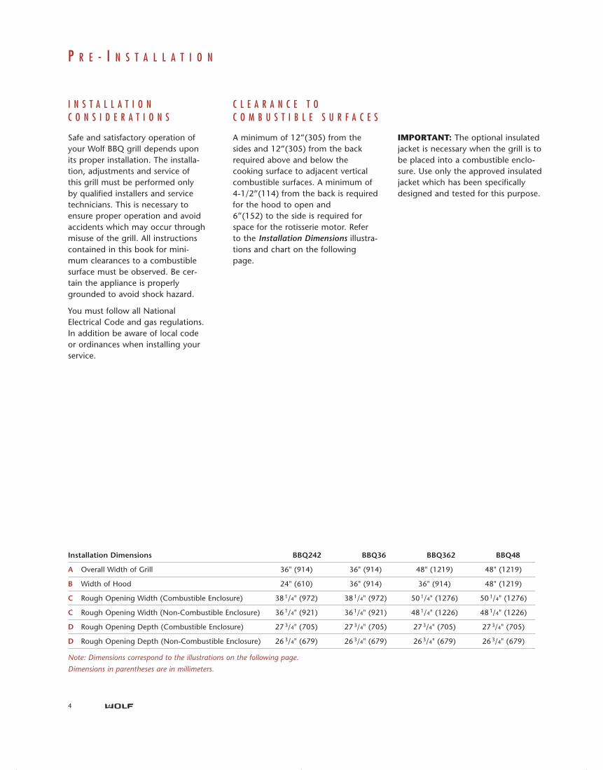
Installation Dimensions BBQ242 BBQ36 BBQ362 BBQ48
A Overall Width of Grill 36" (914) 36" (914) 48" (1219) 48" (1219)
B Width of Hood 24" (610) 36" (914) 36" (914) 48" (1219)
C Rough Opening Width (Combustible Enclosure) 38 1/4" (972) 38 1/4" (972) 50 1/4" (1276) 50 1/4" (1276)
C Rough Opening Width (Non-Combustible Enclosure) 36 1/4" (921) 36 1/4" (921) 48 1/4" (1226) 48 1/4" (1226)
D Rough Opening Depth (Combustible Enclosure) 27 3/4" (705) 27 3/4" (705) 27 3/4" (705) 27 3/4" (705)
D Rough Opening Depth (Non-Combustible Enclosure) 26 3/4" (679) 26 3/4" (679) 26 3/4" (679) 26 3/4" (679)
Note: Dimensions correspond to the illustrations on the following page.
Dimensions in parentheses are in millimeters.
IMPORTANT: The optional insulatedjacket is necessary when the grill is tobe placed into a combustible enclo-sure. Use only the approved insulatedjacket which has been specificallydesigned and tested for this purpose.
gas bbq grills install 803861 rev-b 3-04.qxp 3/23/2004 9:01 AM Page 4
5
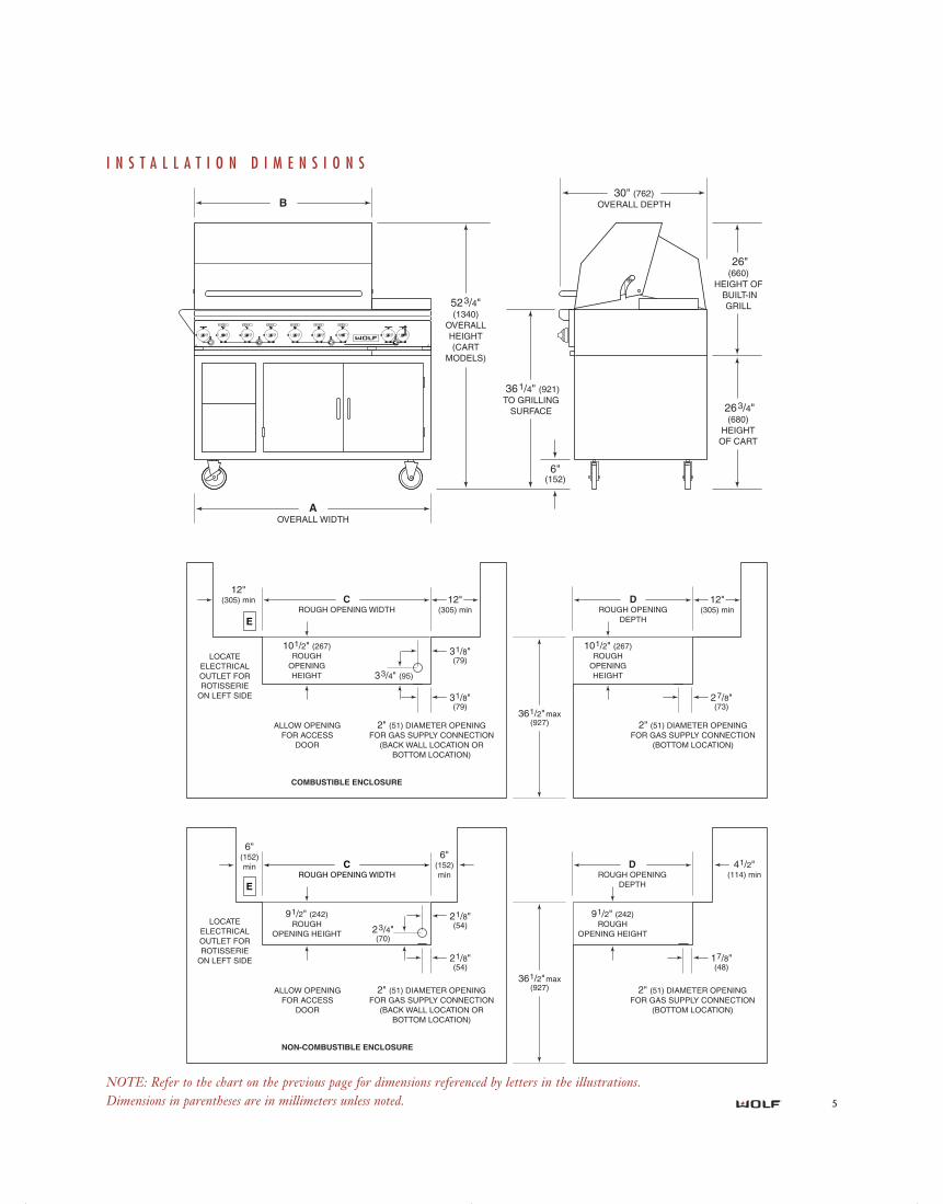
I N S T A L L A T I O N D I M E N S I O N S
361/4" (921)TO GRILLING
SURFACE
523/4"(1340)
OVERALLHEIGHT(CART
MODELS)
263/4"(680)
HEIGHTOF CART
26"(660)
HEIGHT OF BUILT-IN
GRILL
AOVERALL WIDTH
30" (762)OVERALL DEPTHB
6"(152)
361/2"max (927)
CROUGH OPENING WIDTH
COMBUSTIBLE ENCLOSURE
DROUGH OPENING
DEPTH
101/2" (267) ROUGH
OPENING HEIGHT
12" (305) min 12"
(305) min12"
(305) min
101/2" (267) ROUGH
OPENING HEIGHT
31/8"(79)
31/8"(79)
33/4" (95)
2" (51) DIAMETER OPENING FOR GAS SUPPLY CONNECTION
(BACK WALL LOCATION OR BOTTOM LOCATION)
ALLOW OPENING FOR ACCESS
DOOR
LOCATE ELECTRICAL OUTLET FOR ROTISSERIE
ON LEFT SIDE
2" (51) DIAMETER OPENING FOR GAS SUPPLY CONNECTION
(BOTTOM LOCATION)
27/8"(73)
E
361/2"max (927)
NON-COMBUSTIBLE ENCLOSURE
DROUGH OPENING
DEPTH
91/2" (242) ROUGH
OPENING HEIGHT
6" (152) min
6" (152) min
41/2"(114) min
91/2" (242) ROUGH
OPENING HEIGHT
21/8"(54)
21/8"(54)
23/4"(70)
2" (51) DIAMETER OPENING FOR GAS SUPPLY CONNECTION
(BACK WALL LOCATION OR BOTTOM LOCATION)
ALLOW OPENING FOR ACCESS
DOOR
LOCATE ELECTRICAL OUTLET FOR ROTISSERIE
ON LEFT SIDE
2" (51) DIAMETER OPENING FOR GAS SUPPLY CONNECTION
(BOTTOM LOCATION)
17/8"(48)
E
CROUGH OPENING WIDTH
NOTE: Dimensions in parentheses are in millimeters.
NOTE: Refer to the chart on the previous page for dimensions referenced by letters in the illustrations.Dimensions in parentheses are in millimeters unless noted.
gas bbq grills install 803861 rev-b 3-04.qxp 3/23/2004 9:01 AM Page 5
6
I N S T A L L A T I O N
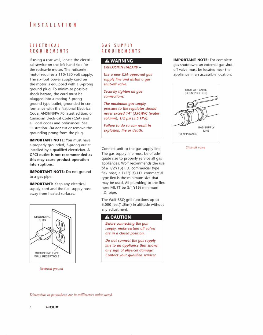
IMPORTANT NOTE: For completegas shutdown, an external gas shut-off valve must be located near theappliance in an accessible location.
SHUT-OFF VALVE (OPEN POSITION)
GAS SUPPLY LINE
TO APPLIANCE
Shut-off valveConnect unit to the gas supply line.The gas supply line must be of ade-quate size to properly service all gasappliances. Wolf recommends the useof a 1/2"(13) I.D. commercial typeflex hose; a 1/2"(13) I.D. commercialtype flex is the minimum size thatmay be used. All plumbing to the flexhose MUST be 3/4"(19) minimumI.D. pipe.
The Wolf BBQ grill functions up to6,000 feet(1.8km) in altitude withoutany adjustment.
G A S S U P P L YR E Q U I R E M E N T S
EXPLOSION HAZARD –
Use a new CSA-approved gassupply line and install a gasshut-off valve.
Securely tighten all gasconnections.
The maximum gas supplypressure to the regulator shouldnever exceed 14" (356)WC (watercolumn); 1/2 psi (3.5 kPa).
Failure to do so can result inexplosion, fire or death.
Before connecting the gassupply, make certain all valvesare in a closed position.
Do not connect the gas supplyline to an appliance that showsany sign of physical damage.Contact your qualified servicer.
E L E C T R I C A LR E Q U I R E M E N T S
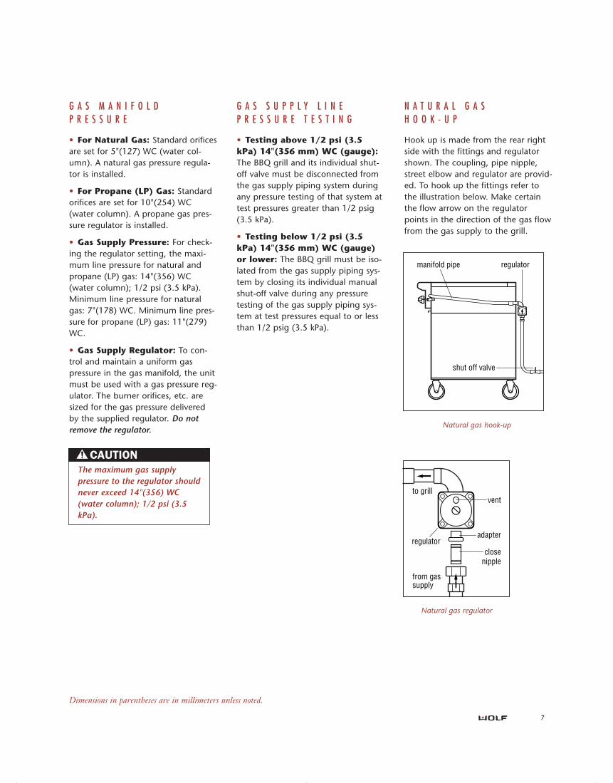
If using a rear wall, locate the electri-cal service on the left hand side forthe rotisserie motor. The rotisseriemotor requires a 110/120 volt supply.The six-foot power supply cord onthe motor is equipped with a 3-prongground plug. To minimize possibleshock hazard, the cord must beplugged into a mating 3-prongground-type outlet, grounded in con-formance with the National ElectricalCode, ANSI/NFPA 70 latest edition, orCanadian Electrical Code (CSA) andall local codes and ordinances. Seeillustration. Do not cut or remove thegrounding prong from the plug.
IMPORTANT NOTE: You must havea properly grounded, 3-prong outletinstalled by a qualified electrician. AGFCI outlet is not recommended asthis may cause product operationinterruptions.
IMPORTANT NOTE: Do not groundto a gas pipe.
IMPORTANT: Keep any electricalsupply cord and the fuel supply hoseaway from heated surfaces.
GROUNDING PLUG
GROUNDING TYPE WALL RECEPTACLE
Electrical ground
Dimensions in parentheses are in millimeters unless noted.
gas bbq grills install 803861 rev-b 3-04.qxp 3/23/2004 9:01 AM Page 6
7
G A S M A N I F O L DP R E S S U R E
• For Natural Gas: Standard orificesare set for 5"(127) WC (water col-umn). A natural gas pressure regula-tor is installed.
• For Propane (LP) Gas: Standardorifices are set for 10"(254) WC(water column). A propane gas pres-sure regulator is installed.
• Gas Supply Pressure: For check-ing the regulator setting, the maxi-mum line pressure for natural andpropane (LP) gas: 14"(356) WC(water column); 1/2 psi (3.5 kPa).Minimum line pressure for naturalgas: 7"(178) WC. Minimum line pres-sure for propane (LP) gas: 11"(279)WC.
• Gas Supply Regulator: To con-trol and maintain a uniform gaspressure in the gas manifold, the unitmust be used with a gas pressure reg-ulator. The burner orifices, etc. aresized for the gas pressure deliveredby the supplied regulator. Do notremove the regulator.
G A S S U P P L Y L I N EP R E S S U R E T E S T I N G
• Testing above 1/2 psi (3.5kPa) 14"(356 mm) WC (gauge):The BBQ grill and its individual shut-off valve must be disconnected fromthe gas supply piping system duringany pressure testing of that system attest pressures greater than 1/2 psig(3.5 kPa).
• Testing below 1/2 psi (3.5kPa) 14"(356 mm) WC (gauge)or lower: The BBQ grill must be iso-lated from the gas supply piping sys-tem by closing its individual manualshut-off valve during any pressuretesting of the gas supply piping sys-tem at test pressures equal to or lessthan 1/2 psig (3.5 kPa).
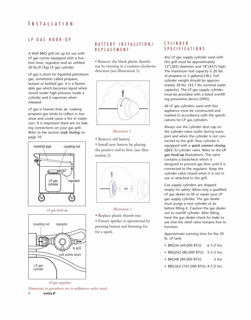
N A T U R A L G A SH O O K - U P
Hook up is made from the rear rightside with the fittings and regulatorshown. The coupling, pipe nipple,street elbow and regulator are provid-ed. To hook up the fittings refer tothe illustration below. Make certainthe flow arrow on the regulatorpoints in the direction of the gas flowfrom the gas supply to the grill.
Natural gas regulator
to grill
from gas supply
vent
adapter
close nipple
regulator
manifold pipe
shut off valve
regulator
Natural gas hook-up
The maximum gas supplypressure to the regulator shouldnever exceed 14"(356) WC(water column); 1/2 psi (3.5kPa).
Dimensions in parentheses are in millimeters unless noted.
gas bbq grills install 803861 rev-b 3-04.qxp 3/23/2004 9:01 AM Page 7
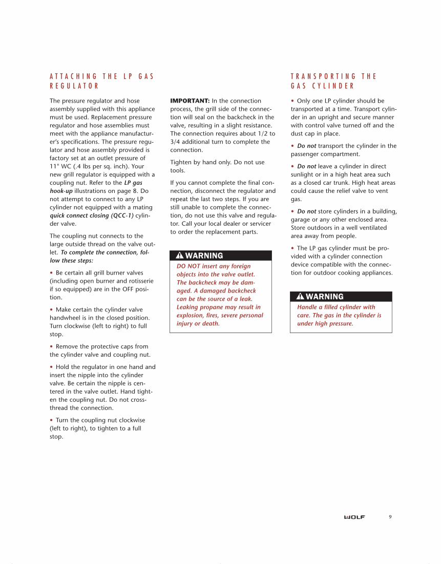
LP gas�cylinder
manifold pipe coupling nut
regulator
C Y L I N D E RS P E C I F I C A T I O N S
Any LP gas supply cylinder used withthis grill must be approximately12”(305) diameter and 18”(457) high.The maximum fuel capacity is 20 lbs.of propane or 5 gallons(3.8L). Fullcylinder weight should be approxi-mately 38 lbs. (43.7 lbs nominal watercapacity). The LP gas supply cylindermust be provided with a listed overfill-ing preventive device (DPD).
All LP gas cylinders used with thisappliance must be constructed andmarked in accordance with the specifi-cations for LP gas cylinders.
Always use the cylinder dust cap onthe cylinder valve outlet during trans-port and when the cylinder is not con-nected to the grill. Your cylinder isequipped with a quick connect closing(QCC-1) cylinder valve. Refer to the LPgas hook-up illustrations. The valvecontains a backcheck which isdesigned to prevent gas flow until it isconnected to the regulator. Keep thecylinder valve closed when it is not inuse or attached to the grill.
Gas supply cylinders are shippedempty for safety. Allow only a qualifiedLP gas dealer to fill or repair your LPgas supply cylinder. The gas dealermust purge a new cylinder of airbefore filling it. Caution the gas dealernot to overfill cylinder. After filling,have the gas dealer check for leaks tosee that the relief valve remains free tofunction.
Approximate running time for the 20lb. LP tank:
• BBQ36 (69,000 BTU) 6-1/2 hrs.
• BBQ242 (80,000 BTU) 5-1/2 hrs.
• BBQ48 (89,000 BTU) 5 hrs.
• BBQ362 (101,000 BTU) 4-1/2 hrs.
L P G A S H O O K - U P
A Wolf BBQ grill set up for use withLP gas comes equipped with a five-foot hose, regulator and an unfilled20 lb.(9.1kg) LP gas cylinder.
LP gas is short for liquefied petroleumgas, sometimes called propane,butane or bottled gas. It is a flamm-able gas which becomes liquid whenstored under high pressure inside acylinder and it vaporizes whenreleased.
LP gas is heavier than air. Leakingpropane gas tends to collect in lowareas and could cause a fire or explo-sion. It is important there are no leak-ing connections on your gas grill.Refer to the section Leak Testing onpage 10.
8
LP gas regulator
coupling nut
LP gas�cylinder
to grill
vent points down
regulator
LP gas hook-up
I N S T A L L A T I O N
B A T T E R Y I N S T A L L T I O N /R E P L A C E M E N T
• Remove the black plastic thumb-nut by twisting in a counter-clockwisedirection (see illustration 1).
• Remove old battery. • Install new battery by placingthe positive end in first. (see illus-tration 2).
• Replace plastic thumb-nut.• Ensure sparker is operational bypressing button and listening forfor a spark.
Illustration 1
AAA
Illustration 2
Dimensions in parentheses are in millimeters unless noted.
gas bbq grills install 803861 rev-b 3-04.qxp 3/23/2004 9:01 AM Page 8
9
IMPORTANT: In the connectionprocess, the grill side of the connec-tion will seal on the backcheck in thevalve, resulting in a slight resistance.The connection requires about 1/2 to3/4 additional turn to complete theconnection.
Tighten by hand only. Do not usetools.
If you cannot complete the final con-nection, disconnect the regulator andrepeat the last two steps. If you arestill unable to complete the connec-tion, do not use this valve and regula-tor. Call your local dealer or servicerto order the replacement parts.
A T T A C H I N G T H E L P G A SR E G U L A T O R
The pressure regulator and hoseassembly supplied with this appliancemust be used. Replacement pressureregulator and hose assemblies mustmeet with the appliance manufactur-er’s specifications. The pressure regu-lator and hose assembly provided isfactory set at an outlet pressure of11" WC (.4 lbs per sq. inch). Yournew grill regulator is equipped with acoupling nut. Refer to the LP gashook-up illustrations on page 8. Donot attempt to connect to any LPcylinder not equipped with a matingquick connect closing (QCC-1) cylin-der valve.
The coupling nut connects to thelarge outside thread on the valve out-let. To complete the connection, fol-low these steps:
• Be certain all grill burner valves(including open burner and rotisserieif so equipped) are in the OFF posi-tion.
• Make certain the cylinder valvehandwheel is in the closed position.Turn clockwise (left to right) to fullstop.
• Remove the protective caps fromthe cylinder valve and coupling nut.
• Hold the regulator in one hand andinsert the nipple into the cylindervalve. Be certain the nipple is cen-tered in the valve outlet. Hand tight-en the coupling nut. Do not cross-thread the connection.
• Turn the coupling nut clockwise(left to right), to tighten to a fullstop.
T R A N S P O R T I N G T H EG A S C Y L I N D E R
• Only one LP cylinder should betransported at a time. Transport cylin-der in an upright and secure mannerwith control valve turned off and thedust cap in place.
• Do not transport the cylinder in thepassenger compartment.
• Do not leave a cylinder in directsunlight or in a high heat area suchas a closed car trunk. High heat areascould cause the relief valve to ventgas.
• Do not store cylinders in a building,garage or any other enclosed area.Store outdoors in a well ventilatedarea away from people.
• The LP gas cylinder must be pro-vided with a cylinder connectiondevice compatible with the connec-tion for outdoor cooking appliances.
Handle a filled cylinder withcare. The gas in the cylinder isunder high pressure.
DO NOT insert any foreignobjects into the valve outlet.The backcheck may be dam-aged. A damaged backcheckcan be the source of a leak.Leaking propane may result inexplosion, fires, severe personalinjury or death.
gas bbq grills install 803861 rev-b 3-04.qxp 3/23/2004 9:01 AM Page 9
10
I N S T A L L A T I O NC H E C K L I S T
• All internal packaging has beenremoved.
• All shipping restraints have beenremoved from the burners.
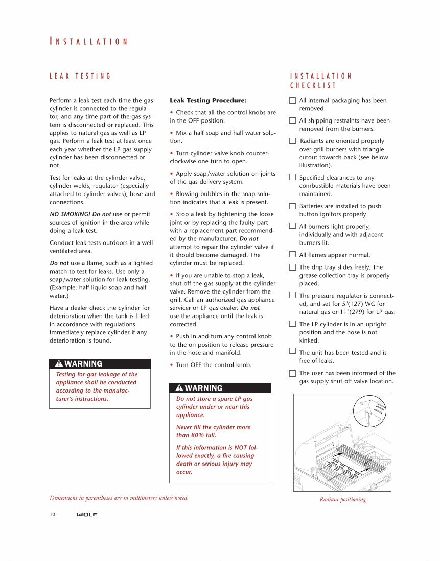
Radiants are oriented properlyover grill burners with trianglecutout towards back (see belowillustration).
• Specified clearances to anycombustible materials have beenmaintained.
Batteries are installed to pushbutton ignitors properly
All burners light properly,individually and with adjacentburners lit.
All flames appear normal.
The drip tray slides freely. Thegrease collection tray is properlyplaced.
The pressure regulator is connect-ed, and set for 5"(127) WC fornatural gas or 11"(279) for LP gas.
The LP cylinder is in an uprightposition and the hose is notkinked.
The unit has been tested and isfree of leaks.
The user has been informed of thegas supply shut off valve location.
I N S T A L L A T I O N
Leak Testing Procedure:
• Check that all the control knobs arein the OFF position.
• Mix a half soap and half water solu-tion.
• Turn cylinder valve knob counter-clockwise one turn to open.
• Apply soap/water solution on jointsof the gas delivery system.
• Blowing bubbles in the soap solu-tion indicates that a leak is present.
• Stop a leak by tightening the loosejoint or by replacing the faulty partwith a replacement part recommend-ed by the manufacturer. Do notattempt to repair the cylinder valve ifit should become damaged. Thecylinder must be replaced.
• If you are unable to stop a leak,shut off the gas supply at the cylindervalve. Remove the cylinder from thegrill. Call an authorized gas applianceservicer or LP gas dealer. Do notuse the appliance until the leak iscorrected.
• Push in and turn any control knobto the on position to release pressurein the hose and manifold.
• Turn OFF the control knob.
L E A K T E S T I N G
Perform a leak test each time the gascylinder is connected to the regula-tor, and any time part of the gas sys-tem is disconnected or replaced. Thisapplies to natural gas as well as LPgas. Perform a leak test at least onceeach year whether the LP gas supplycylinder has been disconnected ornot.
Test for leaks at the cylinder valve,cylinder welds, regulator (especiallyattached to cylinder valves), hose andconnections.
NO SMOKING! Do not use or permitsources of ignition in the area whiledoing a leak test.
Conduct leak tests outdoors in a wellventilated area.
Do not use a flame, such as a lightedmatch to test for leaks. Use only asoap/water solution for leak testing.(Example: half liquid soap and halfwater.)
Have a dealer check the cylinder fordeterioration when the tank is filledin accordance with regulations.Immediately replace cylinder if anydeterioration is found.
Testing for gas leakage of theappliance shall be conductedaccording to the manufac-turer’s instructions. Do not store a spare LP gas
cylinder under or near thisappliance.
Never fill the cylinder morethan 80% full.
If this information is NOT fol-lowed exactly, a fire causingdeath or serious injury mayoccur.
Dimensions in parentheses are in millimeters unless noted. Radiant positioning
gas bbq grills install 803861 rev-b 3-04.qxp 3/23/2004 9:01 AM Page 10
S E R V I C EI N F O R M A T I O N
IMPORTANT NOTE: If the BBQ grilldoes not operate properly, followthese troubleshooting steps:
• Verify that power is being suppliedto the grill.
• Check the electrical and gas con-nections to ensure that the installa-tion has been completed correctly.
• Check that gas valves are turned tothe "ON" position.
• If the appliance still does not work,contact an Wolf Factory AuthorizedService Center. Do not attempt torepair the appliance yourself. Wolf isnot responsible for service required tocorrect a faulty installation.
• To obtain the name and number ofa Wolf Authorized Service Center, callWolf Customer Service at (800) 332-9513 or check our website;www.wolfappliance.com.
• When calling for service, you willneed the BBQ grill model and serialnumbers. Both numbers are listed onthe rating plate, located on the backpanel of the unit.
Be certain to disconnect thegas and electric supplies beforeservicing.
Surface burners can be litmanually with a match. Useextreme caution.
The information and images are the copyright property of Wolf Appliance Company, LLC,an affiliate of Sub-Zero Freezer Company, Inc. Neither this book nor any information or images
contained herein may be copied or used in whole or in part without the express written permissionof Wolf Appliance Company, LLC, an affiliate of Sub-Zero Freezer Company, Inc.
© Wolf Appliance Company, LLC all rights reserved.
11
gas bbq grills install 803861 rev-b 3-04.qxp 3/23/2004 9:01 AM Page 11

WOLF APPLIANCE COMPANY, LLCP. O. Box 44848 • Madison, WI 53744 • 800-332-9513
www.wolfappliance.com
803861 REV-B 3/04
gas bbq grills install 803861 rev-b 3-04.qxp 3/23/2004 9:01 AM Page 12