garmin 421s manual
TRANSCRIPT

8/12/2019 garmin 421s manual
http://slidepdf.com/reader/full/garmin-421s-manual 1/84
GPSMAP®
400/500 seri
owner’s manual
8/12/2019 garmin 421s manual
http://slidepdf.com/reader/full/garmin-421s-manual 2/84
8/12/2019 garmin 421s manual
http://slidepdf.com/reader/full/garmin-421s-manual 3/84
GPSMAP 400/500 Series Owner’s Manual
Introduc
Introduction
This manual includes information for the following products:
GPSMAP® 421/421s GPSMAP 451/451s
GPSMAP 521/521s GPSMAP 526/526s
GPSMAP 551/551s GPSMAP 556/556s
Tips and ShortcutsPress HOME from any screen to return to the Home screen.
Press MENU from any of the main screens to access advanced
settings.
Press and release the Power key to adjust the display settings.
Manual ConventionsIn this manual, when you are instructed to select an item, small
arrows (>) appear in the text. They indicate that you should highlight
a series of items on the screen using the Rocker, and press the
SELECT key after each item. For example, if you see “select
Charts > Navigation Chart,” you should highlight Charts, and
press SELECT. Then highlight Navigation Chart, and press
SELECT again.
•
•
•
Quick LinksTurning the Unit On or Off: page 2.
Acquiring GPS Satellite Signals: page 5.
Inserting and Removing SD Cards: page 6.
Restoring the Original Factory Settings: page 5.
Using the Navigation Chart: page 7.
Changing the Navigation Chart Settings: page 11.
Navigating to a Destination: page 23.
Creating and Using Waypoints: page 25.
Conguring System Settings: page 47.
Using Sonar: page 56.
Alarms and Messages: page 68.
•
•
•
•
•
•
•
•
•
•
•

8/12/2019 garmin 421s manual
http://slidepdf.com/reader/full/garmin-421s-manual 4/84
ii GPSMAP 400/500 Series Owner’s Manua
Introduction
Table of Contents
Introduction........................................................................... iTips and Shortcuts ........................................................................ i
Manual Conventions ..................................................................... i
Quick Links ................................................................................... i
Declaration of Conformity (DoC) ..................................................iv
Product Registration ....................................................................iv
Contact Garmin ............................................................................iv
Getting Started .....................................................................1Unit Overview .............. ............... .............. ............... .............. ....... 1
Turning the Unit On or Off ............................................................ 2
Initializing Unit Settings ................................................................ 2
Adjusting the Backlight................................................................. 3
Using the Keypad ......................................................................... 4 Acquiring GPS Satellite Signals ...................................................4
Using Simulator Mode .................................................................. 5
Viewing System Information ........................................................ 5
Restoring the Original Factory Settings .......................................5
Inserting and Removing SD Cards .............................................. 5
Understanding the Home Screen ................................................. 6
Using Charts ........................................................................7Using the Navigation Chart .......................................................... 7
Changing the Navigation Chart Settings .....................................11
Using the Split Navigation Chart ................................................14
Using Perspective 3D ................................................................ 14
Using Mariner’s Eye 3D ............................................................. 15
Using Fish Eye 3D ..................................................................... 17
Using Fishing Charts .................................................................. 17
Enabling High Resolution Satellite Imagery ...............................18
Viewing Aerial Photos ................................................................ 19
Animated Tide and Current Indicators .......................................20
Detailed Road and POI Data ..................................................... 21
Using Automatic Guidance ......................................................... 21
Using the Chart/Sonar Screen ...................................................22
Where To? ..........................................................................23Navigating to a Destination ........................................................ 23
Creating and Using Waypoints................................................... 25
Creating and Using Routes ........................................................ 26
Using Tracks .............................................................................. 28
Using BlueChart g2 Vision ......................................................... 30
Navigating with a Garmin Autopilot ............................................30
8/12/2019 garmin 421s manual
http://slidepdf.com/reader/full/garmin-421s-manual 5/84
GPSMAP 400/500 Series Owner’s Manual
Introduc
Viewing Information ..........................................................31Viewing a Compass ................................................................... 31
Viewing Numbers ....................................................................... 31
Viewing Trip Information ............................................................ 32
Viewing and Customizing Fuel Gauges and Engine Gauges .... 32
Viewing and Customizing Wind Gauges .................................... 36
Viewing Tide-station Information ................................................ 37
Viewing Current Information ...................................................... 38
Viewing Celestial Information ..................................................... 38
Viewing User Data ..................................................................... 39
Viewing Other Vessels ............................................................... 41
Automatic Identication System ................................................. 41
Confguring the Chartplotter ............................................47Conguring System Settings ...................................................... 47
Conguring Units of Measure .................................................... 47Changing the System Language ................................................ 48
Conguring Navigation Preferences .......................................... 48
Conguring Communications Settings ....................................... 50
Setting Alarms ............................................................................ 52
Setting the Total Fuel Onboard Alarm ........................................ 53
Conguring My Boat .................................................................. 53
Conguring Other Vessels ......................................................... 54
Using Sonar .......................................................................5Understanding the Full Screen ..................................................5
Understanding the Split Frequency Screen ............................... 5
Understanding The Split Zoom Screen ...................................... 5
Understanding the Depth Log Screen ........................................5
Understanding the Temp Log Screen ........................................ 5
Setting Up Sonar ........................................................................ 5
Advanced Sonar Settings .......................................................... 6
Digital Selective Calling (DSC) .........................................6Using the Chartplotter with a VHF Radio ................................... 6
Adding a DSC Contact ............................................................... 6
Viewing the DSC List ................................................................. 6
Receiving Distress Calls ............................................................ 6
Man-Overboard Distress Calls Initiated from a VHF Radio ....... 6
Man-Overboard Distress Calls Initiated from the Chartplotter ... 6Position Tracking ........................................................................ 6
Placing an Individual Routine Call .............................................6
Calling an AIS Target ................................................................. 6
Appendix ............................................................................6Specications ............................................................................. 6
Alarms and Messages ...............................................................6
Capturing Screenshots .............................................................. 7
Caring for the Unit ...................................................................... 7
Software License Agreement ..................................................... 7
Index ...................................................................................7

8/12/2019 garmin 421s manual
http://slidepdf.com/reader/full/garmin-421s-manual 6/84
iv GPSMAP 400/500 Series Owner’s Manua
Introduction
See the Important Safety and Product Information guide in the product box
for product warnings and other important information.
Hg - LAMPS INSIDE THIS PRODUCT CONTAIN
MERCURY AND MUST BE RECYCLED OR DISPOSED OF
ACCORDING TO LOCAL, STATE, OR FEDERAL LAWS.
For more information go to:
www.garmin.com/aboutGarmin/environment/disposal.jsp.
Declaration of Conformity (DoC)
Hereby, Garmin, declares that this product is incompliance with the essential requirements and other
relevant provisions of Directive 1999/5/EC.
To view the full Declaration of Conformity, go to
www.garmin.com/compliance.
Product RegistrationHelp us better support you by completing our online registration
today. Go to http://my.garmin.com. Keep the original sales receipt,
or a photocopy, in a safe place.
Contact GarminContact Garmin Product Support if you have any questions while
using your unit. In the USA, go to www.garmin.com/support, or
contact Garmin USA by phone at (913) 397.8200 or (800) 800.1020
In the UK, contact Garmin (Europe) Ltd. by phone at 0808 2380000
In Europe, go to www.garmin.com/support and click Contact
Support for in-country support information, or contact Garmin
(Europe) Ltd. by phone at +44 (0) 870.8501241.
8/12/2019 garmin 421s manual
http://slidepdf.com/reader/full/garmin-421s-manual 7/84
GPSMAP 400/500 Series Owner’s Manual
Getting Sta
Getting Started
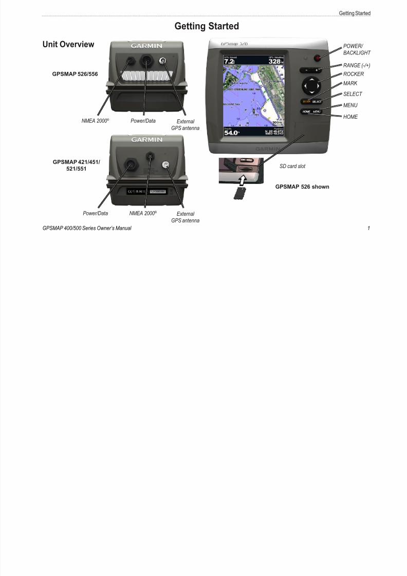
Unit Overview POWER/
BACKLIG
MENU
ROCKER
SELECT
HOME
RANGE (
MARK
SD card slot
GPSMAP 526 shown
GPSMAP 421/451/
521/551
GPSMAP 526/556
Power/Data External
GPS antenna
NMEA 2000 ®
Power/Data External
GPS antenna
NMEA 2000 ®
8/12/2019 garmin 421s manual
http://slidepdf.com/reader/full/garmin-421s-manual 8/84
2 GPSMAP 400/500 Series Owner’s Manua
Getting Started
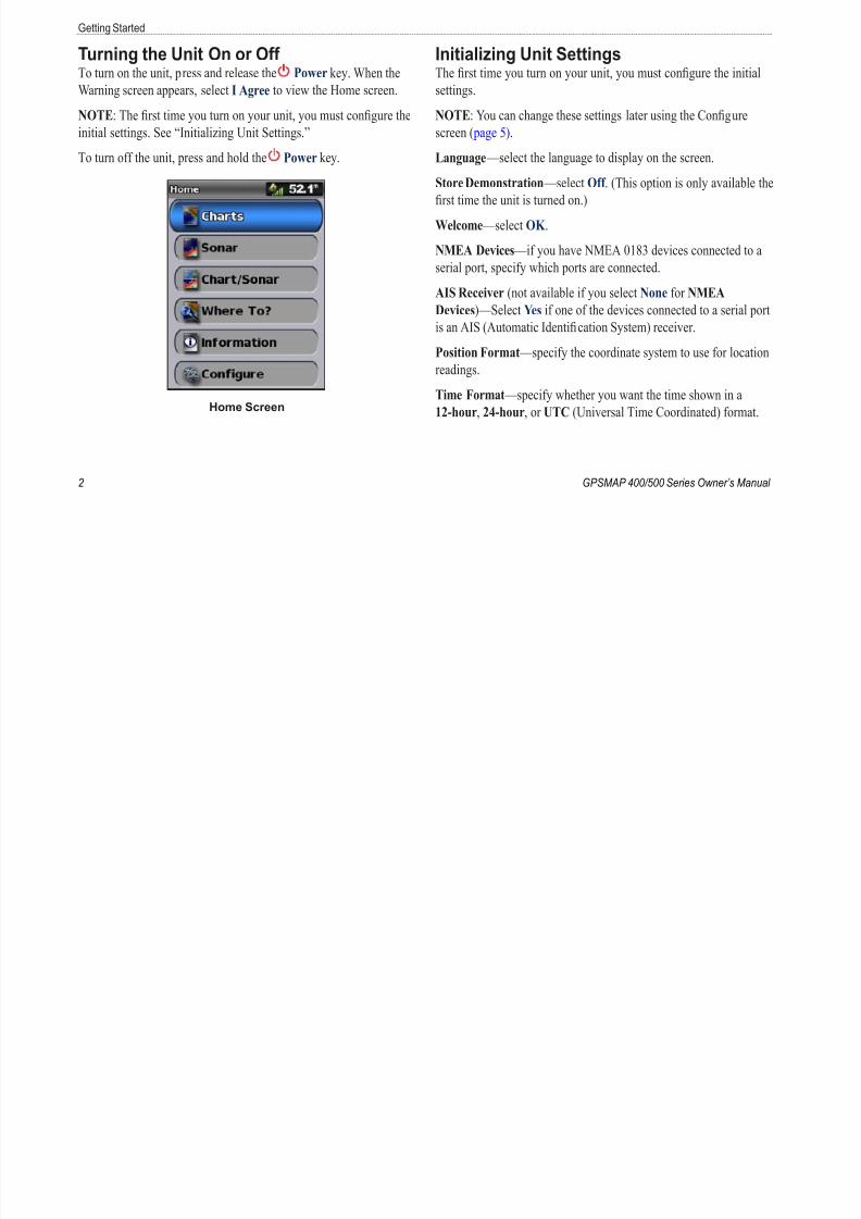
Turning the Unit On or Off To turn on the unit, press and release the Power key. When the
Warning screen appears, select I Agree to view the Home screen.
NOTE: The rst time you turn on your unit, you must congure the
initial settings. See “Initializing Unit Settings.”
To turn off the unit, press and hold the Power key.
Home Screen
Initializing Unit SettingsThe rst time you turn on your unit, you must congure the initial
settings.
NOTE: You can change these settings later using the Congure
screen ( page 5).
Language —select the language to display on the screen.
Store Demonstration —select Off . (This option is only available th
rst time the unit is turned on.)
Welcome —select OK .
NMEA Devices —if you have NMEA 0183 devices connected to a
serial port, specify which ports are connected.
AIS Receiver (not available if you select None for NMEA
Devices)—Select Yes if one of the devices connected to a serial port
is an AIS (Automatic Identication System) receiver.
Position Format —specify the coordinate system to use for location
readings.
Time Format —specify whether you want the time shown in a
12-hour, 24-hour, or UTC (Universal Time Coordinated) format.

8/12/2019 garmin 421s manual
http://slidepdf.com/reader/full/garmin-421s-manual 9/84
GPSMAP 400/500 Series Owner’s Manual
Getting Sta
Time Zone —set the time zone you want displayed for time
readings. If Auto is selected for the Time Zone, the DST option is
not available and is automatically set to Auto.
System Units —specify units for on-screen measurements as
Statute, Metric, or Nautical, or select Custom to individually
dene units of measure for depth, temperature, distance, speed,elevation, volume, and pressure.
Minimum Safe Depth —select the minimum safe depth for your
boat. Refer to your boat specications for more information.
Shallow Water Alarm —only available if you are receiving NMEA
sonar depth data. Select Yes or No.
Minimum Overhead Clearance —select the minimum overhead
clearance for your boat. Refer to your boat specications for more
information.
AIS Alarm Range —select the distance at which an alarm will
sound if an AIS vessel nears your boat ( page 55).
AIS Alarm Time To —select the time within which an alarm will
sound if an AIS vessel is on track to intersect the Safe Zone around
your boat ( page 55).
If a water speed wheel is detected, a message will ask if you want to
calibrate it now. Select Yes or No.
Adjusting the Backlight1. Press and release the Power key.
2. Press left or right on the Rocker to adjust the brightness.
To allow the unit to automatically adjust the backlight based on
ambient light, select Auto Backlight (automatic backlight is
available only on the GPSMAP 526 and 556).

8/12/2019 garmin 421s manual
http://slidepdf.com/reader/full/garmin-421s-manual 10/84
4 GPSMAP 400/500 Series Owner’s Manua
Getting Started
To switch between Day and Night mode:
1. Press and release the Power key.
2. Select Color Mode.
3. Press left or right on the Rocker to switch between modes.
Using the KeypadPOWER/
BACKLIGHT
MENU
ROCKER
SELECT
HOME
RANGE (-/+)
MARK
POWER/BACKLIGHT —Press and hold to turn the unit on or
off. Press and release to adjust the backlight and the day and night
modes.
RANGE (-/+) —Press to adjust the range of the sonar. Press to zoom
in or out on a chart. Press to page up or down on lists.
ROCKER —Press up, down, left, or right to move through menus,
highlight elds, and enter data.
MARK —Press to mark a waypoint.
SELECT —Press to select highlighted items.HOME —Press to return to the Home screen.

8/12/2019 garmin 421s manual
http://slidepdf.com/reader/full/garmin-421s-manual 11/84
GPSMAP 400/500 Series Owner’s Manual
Getting Sta
MENU —Press to access additional settings and conguration
options. Press to return to the previous screen when indicated.
Acquiring GPS Satellite SignalsWhen you turn on the unit, the GPS receiver must collect satellite
data and establish the current location. When the unit acquiressatellite signals, the signal strength bars at the top of the Home
screen are green . When the unit loses satellite signals, the
green bars disappear and the position icon displays a ashing
question mark.
For more information about GPS, visit the Garmin Web site at
www.garmin.com/aboutGPS.
Using Simulator ModeSimulator mode turns the GPS receiver off for use indoors or for
practice. The unit does not track satellites in simulator mode.
WARNING
Do not try to navigate using simulator mode, because the GPS
receiver is turned off. Any satellite signal-strength bars shown are
only simulations and do not represent the strength of actual satellite
signals.
To turn on Simulator mode:
1. From the Home screen, select Confgure > System >
Simulator .
2. Select Setup to set speed, track control, and position.
Viewing System InformationYou can view the software version, the basemap version,
supplemental map information (if applicable), and the unit ID
number for your chartplotter. You may need this information to
update the system software or to purchase additional map data.
From the home screen, select Confgure > System > System
Information.
Restoring the Original Factory SettingsNOTE: This procedure deletes all settings information you have
entered.
1. From the Home screen, select Confgure > System > System
Information > Factory Settings.
2. Select Yes to restore all factory settings, or select No to cance
The unit reboots and prompts you to adjust unit settings (page
8/12/2019 garmin 421s manual
http://slidepdf.com/reader/full/garmin-421s-manual 12/84
6 GPSMAP 400/500 Series Owner’s Manua
Getting Started
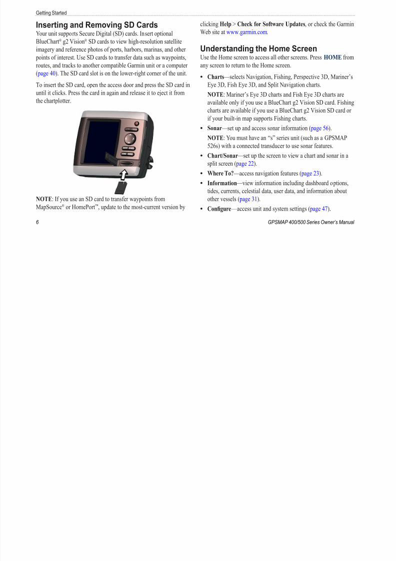
Inserting and Removing SD CardsYour unit supports Secure Digital (SD) cards. Insert optional
BlueChart® g2 Vision® SD cards to view high-resolution satellite
imagery and reference photos of ports, harbors, marinas, and other
points of interest. Use SD cards to transfer data such as waypoints,
routes, and tracks to another compatible Garmin unit or a computer( page 40). The SD card slot is on the lower-right corner of the unit.
To insert the SD card, open the access door and press the SD card in
until it clicks. Press the card in again and release it to eject it from
the chartplotter.
NOTE: If you use an SD card to transfer waypoints from
MapSource® or HomePort™, update to the most-current version by
clicking Help > Check for Software Updates, or check the Garmin
Web site at www.garmin.com.
Understanding the Home ScreenUse the Home screen to access all other screens. Press HOME from
any screen to return to the Home screen.
Charts —selects Navigation, Fishing, Perspective 3D, Mariner’s
Eye 3D, Fish Eye 3D, and Split Navigation charts.
NOTE: Mariner’s Eye 3D charts and Fish Eye 3D charts are
available only if you use a BlueChart g2 Vision SD card. Fishing
charts are available if you use a BlueChart g2 Vision SD card or
if your built-in map supports Fishing charts.
Sonar —set up and access sonar information ( page 56).NOTE: You must have an “s” series unit (such as a GPSMAP
526s) with a connected transducer to use sonar features.
Chart/Sonar —set up the screen to view a chart and sonar in a
split screen ( page 22).
Where To? —access navigation features ( page 23).
Information —view information including dashboard options,
tides, currents, celestial data, user data, and information about
other vessels ( page 31).
Confgure —access unit and system settings ( page 47).
•
•
•
•
•
•
8/12/2019 garmin 421s manual
http://slidepdf.com/reader/full/garmin-421s-manual 13/84
GPSMAP 400/500 Series Owner’s Manual
Using Ch
Using Charts
Your chartplotter has a worldwide basemap or BlueChart g2
cartography for either the USA shoreline or a specic country.
Navigation Chart —displays all relevant navigation data
available on your preloaded maps, including buoys, lights,cables, depth soundings, marinas, and tide stations, in an
overhead view.
Perspective 3D —provides a view from above and behind the
boat (according to your course), and provides a visual navigation
aid.
Split Navigation Chart —displays two different zoom levels of
the Navigation chart at the same time.
Mariner’s Eye 3D charts and Fish Eye 3D charts are available
only if you use a BlueChart g2 Vision SD card. Fishing charts
are available if you use a BlueChart g2 Vision SD card or if your
built-in map supports Fishing charts.
Fishing Chart —provides a view of the chart with enhanced
bottom contours and without navigational data. This chart works
well for offshore deep-sea shing.
Fish Eye 3D —provides an underwater 3D view that visuallyrepresents the sea oor according to the information on the chart.
•
•
•
•
•
Mariner’s Eye 3D —provides a view from above and behind
the boat as a three-dimensional navigation aid. The BlueChart
g2 Vision Mariner’s Eye 3D is more detailed than the preloade
data.
NOTE: If you are using a GPSMAP 421, 521, or 526 (includin
“s” models), you must insert an optional BlueChart g2 Vision preprogrammed SD card to view detailed Navigation and
Mariner’s Eye charts.
Using the Navigation ChartUse the Navigation chart to plan your course, to view map
information, and as a navigational aid.
To access a Navigation chart, from the Home screen, select
Charts > Navigation Chart.
•
8/12/2019 garmin 421s manual
http://slidepdf.com/reader/full/garmin-421s-manual 14/84
8 GPSMAP 400/500 Series Owner’s Manua
Using Charts
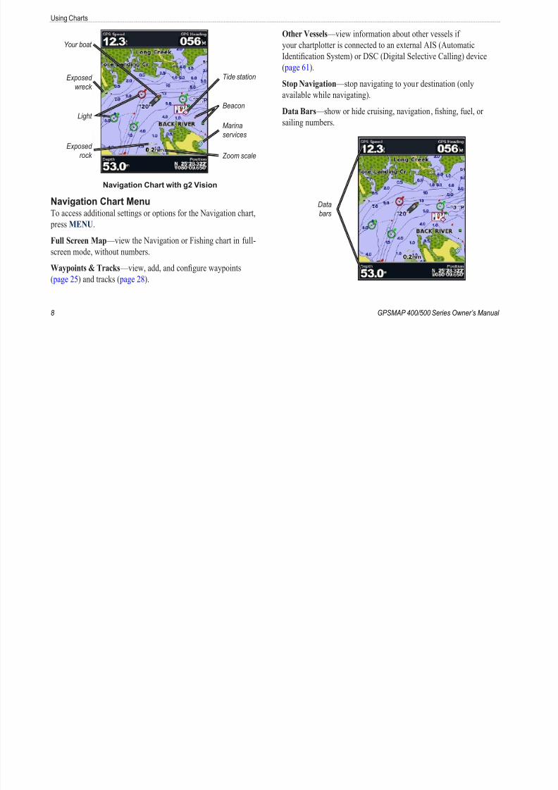
Light
Beacon
Exposed
wreck
Your boat
Marina
services
Exposed
rock
Tide station
Zoom scale
Navigation Chart with g2 Vision
Navigation Chart MenuTo access additional settings or options for the Navigation chart,
press MENU.
Full Screen Map —view the Navigation or Fishing chart in full-
screen mode, without numbers.
Waypoints & Tracks —view, add, and congure waypoints
( page 25) and tracks ( page 28).
Other Vessels —view information about other vessels if
your chartplotter is connected to an external AIS (Automatic
Identication System) or DSC (Digital Selective Calling) device
( page 61).
Stop Navigation —stop navigating to your destination (only
available while navigating).
Data Bars —show or hide cruising, navigation, shing, fuel, or
sailing numbers.
Data
bars
8/12/2019 garmin 421s manual
http://slidepdf.com/reader/full/garmin-421s-manual 15/84

8/12/2019 garmin 421s manual
http://slidepdf.com/reader/full/garmin-421s-manual 16/84
10 GPSMAP 400/500 Series Owner’s Manua
Using Charts
Other features common to most charts include depth contour
lines (with deep water represented in white), intertidal zones, spot
soundings (as depicted on the original paper chart), navigational aids
and symbols, and obstructions and cable areas.
Navigating to a Point on the Chart1. From the Home screen, select Charts.
2. Select Navigation Chart, Fishing Chart, or Split Navigation
Chart.
3. Use the Rocker to select the point on the chart to which you
want to go.
4. Press SELECT.
5. Select Navigate To.
6. Select Go To (or Guide To when using a preprogrammedBlueChart g2 Vision card for Automatic Guidance).
7. Follow the colored line on the screen to the destination.
To create a route to a point on the chart, see page 26.
Panning the Navigation ChartUse the Rocker to move the map pointer ( ) away from your
current location and to scroll to other areas on the Navigation chart.
As you pan past the edge of the current map display, the screen
scrolls forward to provide continuous map coverage.
As you move the map pointer, you can view the distance and
bearing from your current location and the map pointer’s location
coordinates, in the lower-right corner of the map.
To pan the map, press up, down, right, or left on the Rocker .
Map
pointer
To stop panning, press MENU, and then select Stop Panning.
Zooming In and Out on the MapThe Range (-/+) keys control the zoom level, indicated by the scale
at the bottom of the Navigation chart ( ). The bar under thenumber represents that distance on the map.
8/12/2019 garmin 421s manual
http://slidepdf.com/reader/full/garmin-421s-manual 17/84
GPSMAP 400/500 Series Owner’s Manual
Using Ch
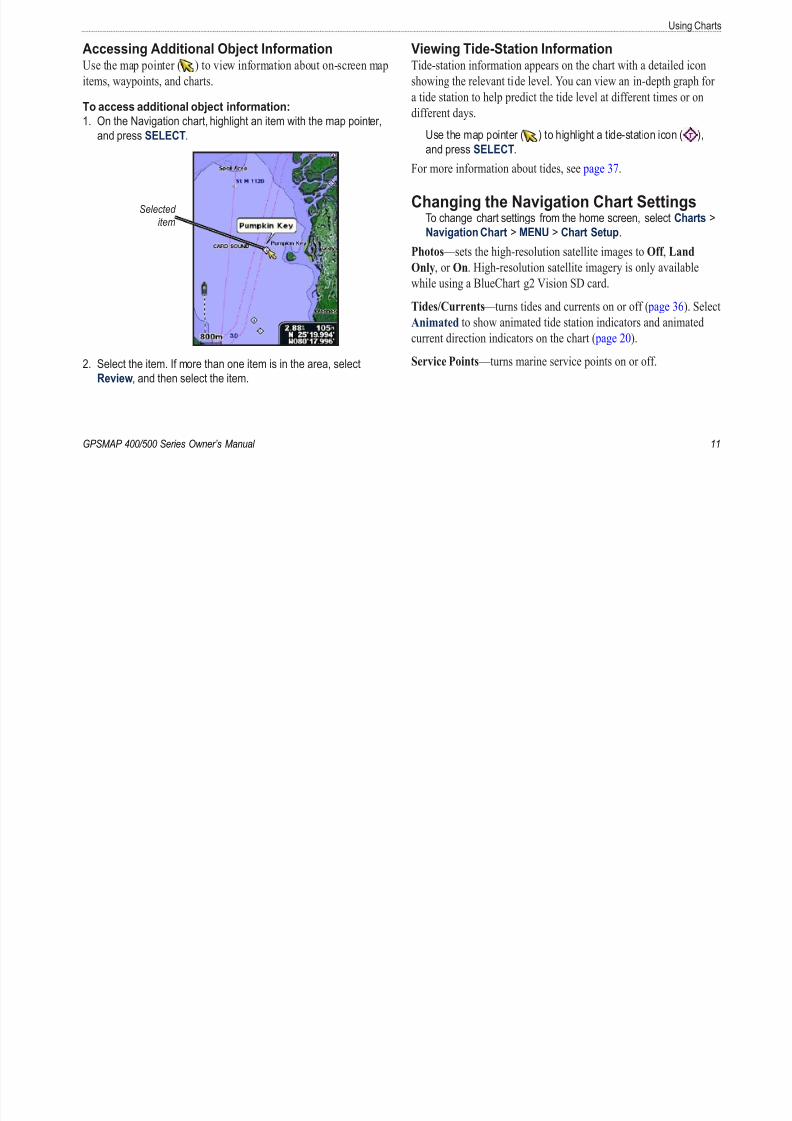
Accessing Additional Object InformationUse the map pointer ( ) to view information about on-screen map
items, waypoints, and charts.
To access additional object information:
1. On the Navigation chart, highlight an item with the map pointer,
and press SELECT.
Selected
item
2. Select the item. If more than one item is in the area, select
Review, and then select the item.
Viewing Tide-Station InformationTide-station information appears on the chart with a detailed icon
showing the relevant tide level. You can view an in-depth graph fo
a tide station to help predict the tide level at different times or on
different days.
Use the map pointer ( ) to highlight a tide-station icon ( ),and press SELECT.
For more information about tides, see page 37.
Changing the Navigation Chart Settings To change chart settings from the home screen, select Charts
Navigation Chart > MENU > Chart Setup.
Photos —sets the high-resolution satellite images to Off , Land
Only, or On. High-resolution satellite imagery is only availablewhile using a BlueChart g2 Vision SD card.
Tides/Currents —turns tides and currents on or off ( page 36). Sel
Animated to show animated tide station indicators and animated
current direction indicators on the chart ( page 20).
Service Points —turns marine service points on or off.

8/12/2019 garmin 421s manual
http://slidepdf.com/reader/full/garmin-421s-manual 18/84
12 GPSMAP 400/500 Series Owner’s Manua
Using Charts
Roses —displays a compass rose around your boat, indicating
compass direction. True wind direction or apparent wind direction
displays if the unit is connected to a compatible marine wind sensor.
Wind direction
indicator
Compass rose
Changing the Chart Appearance From the Home screen, select Charts > Navigation Chart >
MENU > Chart Setup > Chart Appearance.
Orientation —changes the perspective of the map display.
North Up —sets the top of the map display to a north heading.Head Up —sets the map display to the current track heading.
•
•
Course Up —sets the map so the direction of navigation is
always up. The heading line appears vertically on the screen if
shown.
Detail —adjusts the amount of detail shown on the map at different
zoom levels.
Press right on
the Rocker to
increase map
detail.
Press left on
the Rocker to
decrease map
detail.
•
8/12/2019 garmin 421s manual
http://slidepdf.com/reader/full/garmin-421s-manual 19/84
GPSMAP 400/500 Series Owner’s Manual
Using Ch
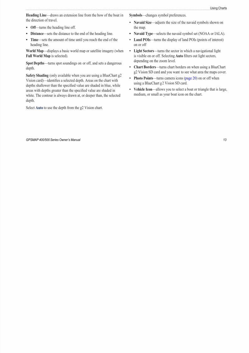
Heading Line —draws an extension line from the bow of the boat in
the direction of travel.
Off —turns the heading line off.
Distance —sets the distance to the end of the heading line.
Time —sets the amount of time until you reach the end of the
heading line.
World Map —displays a basic world map or satellite imagery (when
Full World Map is selected).
Spot Depths —turns spot soundings on or off, and sets a dangerous
depth.
Safety Shading (only available when you are using a BlueChart g2
Vision card)—identies a selected depth. Areas on the chart with
depths shallower than the specied value are shaded in blue, while
areas with depths greater than the specied value are shaded in
white. The contour is always drawn at, or deeper than, the selected
depth.
Select Auto to use the depth from the g2 Vision chart.
•
•
•
Symbols —changes symbol preferences.
Navaid Size —adjusts the size of the navaid symbols shown on
the map.
Navaid Type —selects the navaid symbol set (NOAA or IALA
Land POIs —turns the display of land POIs (points of interest
on or off
Light Sectors —turns the sector in which a navigational light
is visible on or off. Selecting Auto lters out light sectors,
depending on the zoom level.
Chart Borders —turns chart borders on when using a BlueCh
g2 Vision SD card and you want to see what area the maps cov
Photo Points —turns camera icons ( page 20) on or off when
using a BlueChart g2 Vision SD card.Vehicle Icon —allows you to select a boat or triangle that is lar
medium, or small as your boat icon on the chart.
•
•
•
•
•
•
•

8/12/2019 garmin 421s manual
http://slidepdf.com/reader/full/garmin-421s-manual 20/84
U i Ch

8/12/2019 garmin 421s manual
http://slidepdf.com/reader/full/garmin-421s-manual 21/84
GPSMAP 400/500 Series Owner’s Manual
Using Ch
Waypoints —view, sort, or lter existing waypoints, or create
new ones.
New Waypoint —create and edit a new waypoint.
Active Tracks —manage tracks ( page 28).
Saved Tracks —view a list of tracks that have been saved.
Other Vessels —view information about other vessels. To view
information about other vessels, your unit must be connected to an
external AIS (Automatic Identication System) or DSC (Digital
Selective Calling) device ( page 61).
Data Bars ( page 8)—show or hide the numbers for cruising,
navigation, shing, fuel, sailing, or the compass tape ( page 9).
Chart Appearance —customize the Perspective 3D chart.
Range Rings —toggles the range rings on or off to provide
distance measurement.
Lane Width —adjusts the width of the course line drawn when
navigating. This setting also affects routes (Route To), but does
not affect automatic guidance (Guide To).
Using Mariner’s Eye 3D
A BlueChart g2 Vision SD card offers Mariner’s Eye 3D that provides a detailed three-dimensional view from above and behind
the boat (according to your course), and provides a visual navigation
•
•
•
•
•
•
aid. This view is helpful when navigating tricky shoals, reefs,
bridges, or channels, and is benecial when trying to identify entr
routes and exit routes in unfamiliar harbors or anchorages.
Mariner's Eye 3D Navigation Chart
Press the Range (+) key to move the view closer to your boat
and lower to the water. Press the Range (-) key to move the v
away from the boat. The scale ( ) temporarily appears a
the bottom of the screen.
Using Charts
8/12/2019 garmin 421s manual
http://slidepdf.com/reader/full/garmin-421s-manual 22/84
16 GPSMAP 400/500 Series Owner’s Manua
Using Charts
To view details about navaids such as beacons, lights, and
obstructions:
1. Use the Rocker to point to the navaid. When the cursor is over
the navaid, the navaid is highlighted.
2. Press SELECT to view details about the navaid.
Mariner’s Eye 3D SettingsTo access additional settings or options from the Mariner’s Eye 3D
screen, press MENU.
For settings and options related to Waypoints & Tracks, Other
Vessels, and Data Bars, see “Navigation Chart Menu” on page 8.
To customize the appearance of the Mariner’s Eye 3D screen,
select MENU > Chart Appearance.
Style —Selects how chart data is displayed over 3D terrain.Classic —uses color schemes to indicate 3D terrain.
Charts —provides chart information in a 3D view.
Photos —provides satellite photo imagery in addition to chart
information.
•
•
•
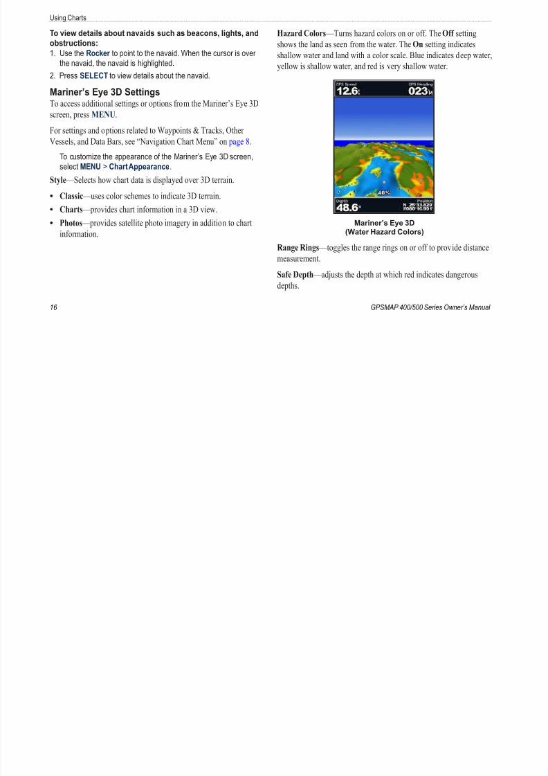
Hazard Colors —Turns hazard colors on or off. The Off setting
shows the land as seen from the water. The On setting indicates
shallow water and land with a color scale. Blue indicates deep water
yellow is shallow water, and red is very shallow water.
Mariner’s Eye 3D
(Water Hazard Colors)
Range Rings —toggles the range rings on or off to provide distance
measurement.
Safe Depth —adjusts the depth at which red indicates dangerousdepths.
Using Ch
8/12/2019 garmin 421s manual
http://slidepdf.com/reader/full/garmin-421s-manual 23/84
GPSMAP 400/500 Series Owner’s Manual
Using Ch
Lane Width —adjusts the width of the course line drawn when
navigating. This setting also affects routes (Route To), but does not
affect automatic guidance (Guide To).
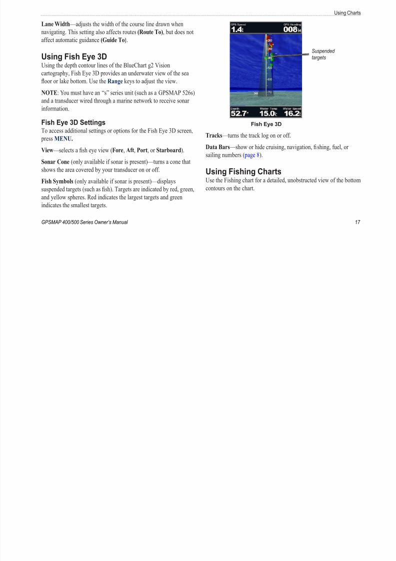
Using Fish Eye 3D
Using the depth contour lines of the BlueChart g2 Visioncartography, Fish Eye 3D provides an underwater view of the sea
oor or lake bottom. Use the Range keys to adjust the view.
NOTE: You must have an “s” series unit (such as a GPSMAP 526s)
and a transducer wired through a marine network to receive sonar
information.
Fish Eye 3D Settings
To access additional settings or options for the Fish Eye 3D screen, press MENU.
View —selects a sh eye view (Fore, Aft, Port, or Starboard).
Sonar Cone (only available if sonar is present)—turns a cone that
shows the area covered by your transducer on or off.
Fish Symbols (only available if sonar is present)—displays
suspended targets (such as sh). Targets are indicated by red, green,
and yellow spheres. Red indicates the largest targets and greenindicates the smallest targets.
Suspended
targets
Fish Eye 3D
Tracks —turns the track log on or off.
Data Bars —show or hide cruising, navigation, shing, fuel, or
sailing numbers ( page 8).
Using Fishing ChartsUse the Fishing chart for a detailed, unobstructed view of the bott
contours on the chart.
Using Charts

8/12/2019 garmin 421s manual
http://slidepdf.com/reader/full/garmin-421s-manual 24/84
18 GPSMAP 400/500 Series Owner’s Manua
Using Charts
The Fishing chart uses detailed bathymetric data on a
preprogrammed BlueChart g2 Vision SD card, and is best for
offshore deep-sea shing.
From the Home screen, select Charts > Fishing Chart.
To access additional settings or options from the Fishing chart,
press MENU.
Navaids —displays navigational aids, such as beacons, lights, and
obstructions.
For settings and options related to Full Screen Map, Waypoints &
Tracks, Other Vessels, and Data Bars, see “Navigation Chart Menu”
on page 8.
To customize the appearance of the Fishing Chart screen, select
MENU > Chart Setup (page 11).
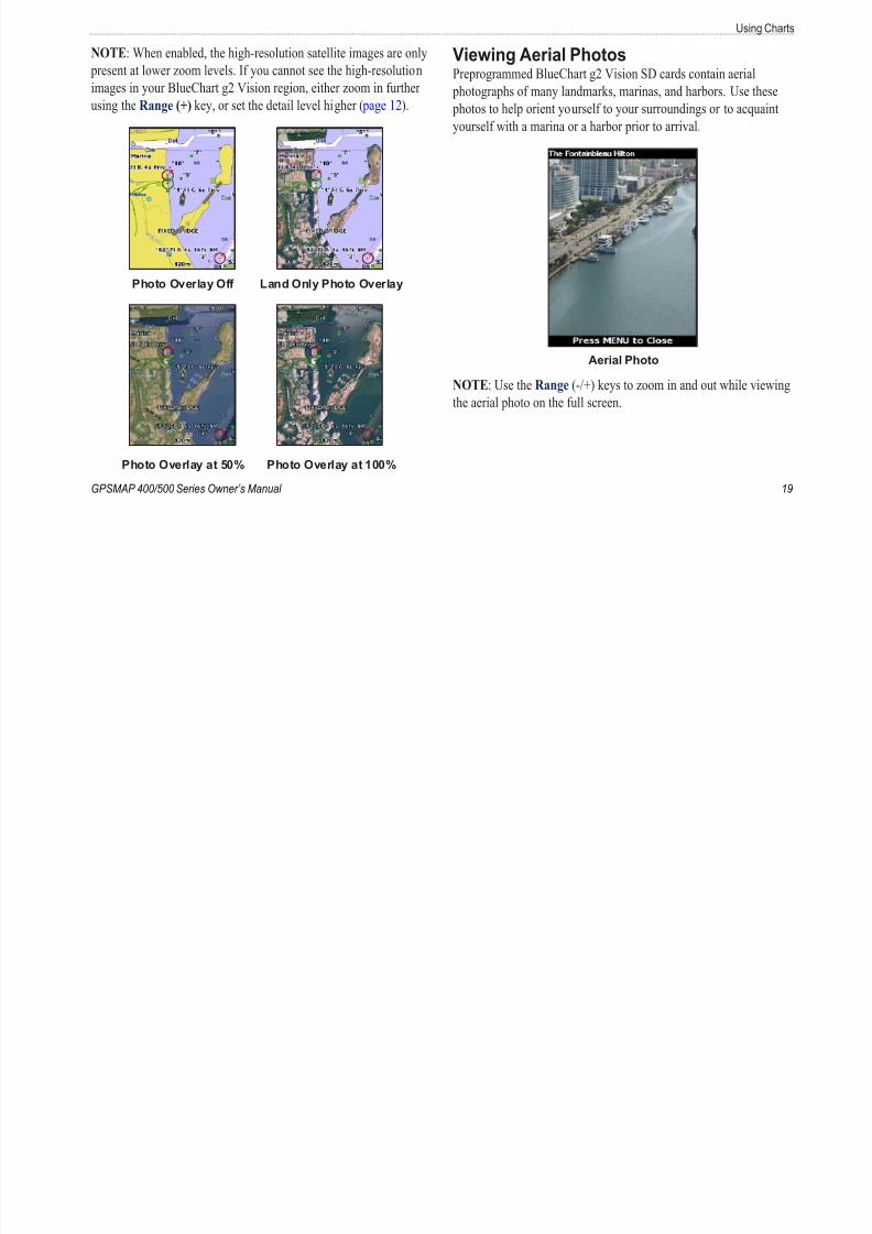
Enabling High Resolution Satellite ImageryYou can overlay high-resolution satellite images on the land, sea, or
both portions of the Navigation chart when using a preprogrammed
BlueChart g2 Vision SD card.
To enable satellite imagery:
1. While viewing the Navigation chart, press MENU.
2. Select Chart Setup > Photos.
3. Select one of the following:
Off —standard chart information is shown on the map.
Land Only—standard chart information is shown on water
with photos overlaying the land.
On—photos overlay both the water and the land at a specie
opacity. The higher you set the percentage, the more the
satellite photos will cover both land and water.
•
•
•
Using Ch
8/12/2019 garmin 421s manual
http://slidepdf.com/reader/full/garmin-421s-manual 25/84
GPSMAP 400/500 Series Owner’s Manual
Using Ch
NOTE: When enabled, the high-resolution satellite images are only
present at lower zoom levels. If you cannot see the high-resolution
images in your BlueChart g2 Vision region, either zoom in further
using the Range (+) key, or set the detail level higher ( page 12).
Photo Overlay Off Land Only Photo Overlay
Photo Overlay at 50% Photo Overlay at 100%
Viewing Aerial PhotosPreprogrammed BlueChart g2 Vision SD cards contain aerial
photographs of many landmarks, marinas, and harbors. Use these
photos to help orient yourself to your surroundings or to acquaint
yourself with a marina or a harbor prior to arrival.
Aerial Photo
NOTE: Use the Range (-/+) keys to zoom in and out while viewi
the aerial photo on the full screen.
Using Charts

8/12/2019 garmin 421s manual
http://slidepdf.com/reader/full/garmin-421s-manual 26/84
20 GPSMAP 400/500 Series Owner’s Manua
Using Charts
To access aerial photos from the Navigation chart:
Use the Rocker to highlight a camera icon with the pointer, and
select Aerial Photo or Review.
Perspective
Overhead
Animated Tide and Current IndicatorsYou can view indicators for animated tide station and current
direction on the Navigation chart or the Fishing chart. To do so,
information for tide station and current direction must be available
in your preloaded map or BlueChart g2 Vision region. You must als
select the Animated value for theTides/Currents setting ( page 11).
An indicator for a tide station appears on the chart
as a vertical bar graph with an arrow. A red arrow
pointing downward indicates a falling tide, and a blue
arrow pointing upward indicates a rising tide. When
you move the cursor over the tide station indicator,
the height of the tide at the station appears above the
station indicator.
Tide
Station
with Fallin
Tide
Tide
Station
with Fallin
Tide
Using Ch
8/12/2019 garmin 421s manual
http://slidepdf.com/reader/full/garmin-421s-manual 27/84
GPSMAP 400/500 Series Owner’s Manual
g
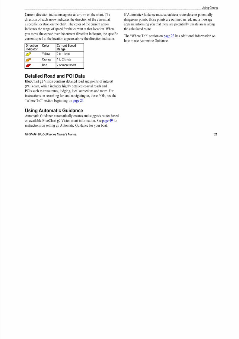
Current direction indicators appear as arrows on the chart. The
direction of each arrow indicates the direction of the current at
a specic location on the chart. The color of the current arrow
indicates the range of speed for the current at that location. When
you move the cursor over the current direction indicator, the specic
current speed at the location appears above the direction indicator.
DirectionIndicator
Color Current SpeedRange
Yellow 0 to 1 knot
Orange 1 to 2 knots
Red 2 or more knots
Detailed Road and POI DataBlueChart g2 Vision contains detailed road and points of interest(POI) data, which includes highly detailed coastal roads and
POIs such as restaurants, lodging, local attractions and more. For
instructions on searching for, and navigating to, these POIs, see the
“Where To?” section beginning on page 23.
Using Automatic GuidanceAutomatic Guidance automatically creates and suggests routes based
on available BlueChart g2 Vision chart information. See page 49 forinstructions on setting up Automatic Guidance for your boat.
If Automatic Guidance must calculate a route close to potentially
dangerous points, those points are outlined in red, and a message
appears informing you that there are potentially unsafe areas alon
the calculated route.
The “Where To?” section on page 23 has additional information o
how to use Automatic Guidance.
Using Charts

8/12/2019 garmin 421s manual
http://slidepdf.com/reader/full/garmin-421s-manual 28/84
22 GPSMAP 400/500 Series Owner’s Manua
g
Using the Chart/Sonar ScreenNOTE: The Chart/Sonar screen, like the Sonar screen, is only
available when using a sonar capable unit with a transducer attached.
Use the Chart/Sonar screen to view the Navigation chart, Fishing
chart, Mariner’s Eye 3D, or Fish Eye 3D and sonar at the same time.
To view a split chart/sonar screen:
1. From the Home screen, select Chart/Sonar .
2. Select the type of chart on the split screen.
Navigation
chart screen
Sonar
screen
Navigation/Sonar Combination
To access additional settings or options for the chart/sonar
screen, press MENU.
Where

8/12/2019 garmin 421s manual
http://slidepdf.com/reader/full/garmin-421s-manual 29/84
GPSMAP 400/500 Series Owner’s Manual
Where To?
Use the Where To? option on the Home screen to search for, and
navigate to, waypoints, routes, tracks, and services such as nearby
fuel, repairs, and ramps.
NOTE: You must create waypoints and routes before you can
navigate to them.
You can navigate to a destination using one of three methods: Go
To, Route To, or Guide To.
Go To —takes you directly to the destination.
Route To —creates a route from your location to a destination,
allowing you to add turns to the route.
Guide To —uses BlueChart g2 Vision chart data to suggest the best path to your destination. You must be using a BlueChart g2
Vision SD card for this option to appear.
CAUTION
Guide To does not ensure obstacle and bottom clearance. For safety,
always resolve any discrepancies or questions before continuing
navigation.
•
•
•
Navigating to a DestinationYou can search for, and navigate to, waypoints, routes, tracks, and
services such as nearby fuel, repairs, and ramps.
To begin navigating:
1. From the Home screen, select Where To?.
2. Select the category to which you want to navigate.
Where To?

8/12/2019 garmin 421s manual
http://slidepdf.com/reader/full/garmin-421s-manual 30/84
24 GPSMAP 400/500 Series Owner’s Manua
3. Select a destination.
NOTE: Press the right or left arrow to view additional
information or to display the location on a chart.
4. Select Navigate To.
5. Select Go To.
OR
Select Guide To when using a preprogrammed BlueChart g2
Vision card to use Automatic Guidance.
6. Follow the colored line on the screen to the destination.
To stop navigating:
Press MENU, and select Stop Navigating.
To search for a destination by name:
1. From the Home screen, select Where To? > Search by Name.
2. Use the Rocker to select characters and spell at least a portion
of the name of your destination.
3. Press SELECT to view the 50 nearest destinations that contain
your search criteria.
4. Select the location > Navigate To > Go To or Route To (orGuide To when using a preprogrammed BlueChart g2 Vision
card).
Where
8/12/2019 garmin 421s manual
http://slidepdf.com/reader/full/garmin-421s-manual 31/84
GPSMAP 400/500 Series Owner’s Manual
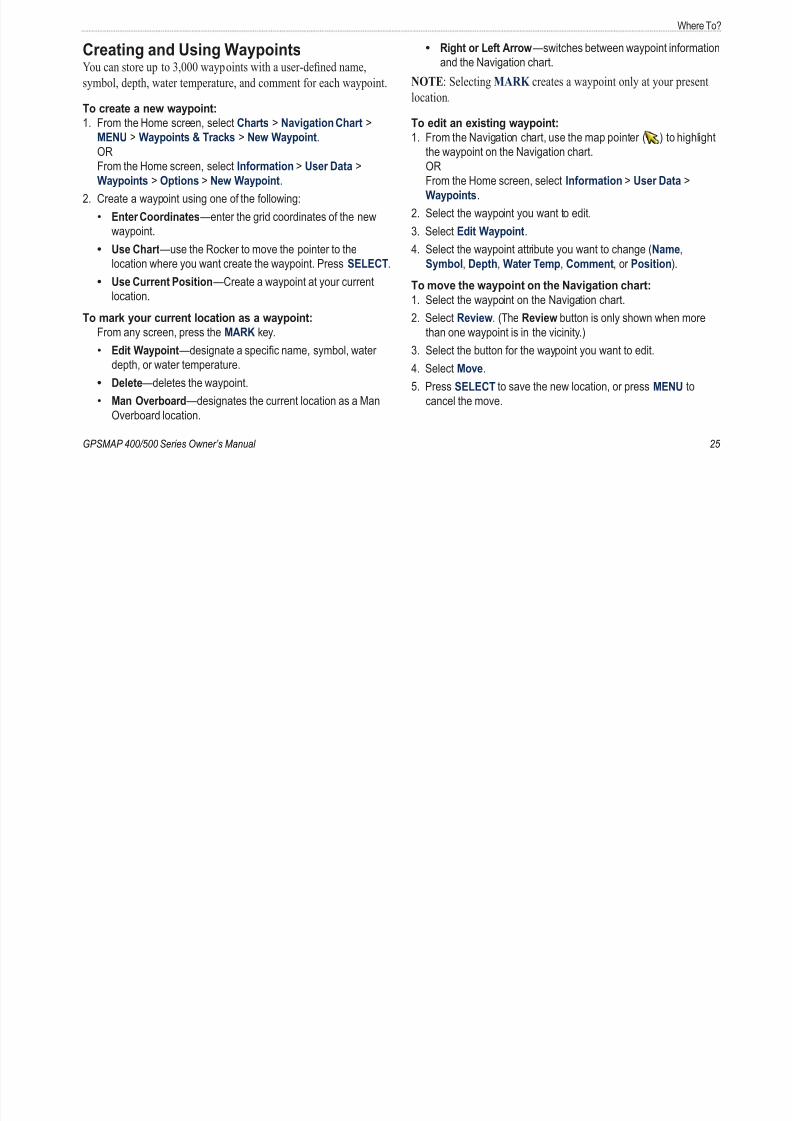
Creating and Using WaypointsYou can store up to 3,000 waypoints with a user-dened name,
symbol, depth, water temperature, and comment for each waypoint.
To create a new waypoint:
1. From the Home screen, select Charts > Navigation Chart >
MENU > Waypoints & Tracks > New Waypoint.OR
From the Home screen, select Information > User Data >
Waypoints > Options > New Waypoint.
2. Create a waypoint using one of the following:
Enter Coordinates—enter the grid coordinates of the new
waypoint.
Use Chart—use the Rocker to move the pointer to the
location where you want create the waypoint. Press SELECT.Use Current Position—Create a waypoint at your current
location.
To mark your current location as a waypoint:
From any screen, press the MARK key.
Edit Waypoint—designate a specic name, symbol, water
depth, or water temperature.
Delete—deletes the waypoint.
Man Overboard—designates the current location as a ManOverboard location.
•
•
•
•
•
•
Right or Left Arrow—switches between waypoint informat
and the Navigation chart.
NOTE: Selecting MARK creates a waypoint only at your presen
location.
To edit an existing waypoint:
1. From the Navigation chart, use the map pointer ( ) to highligthe waypoint on the Navigation chart.
OR
From the Home screen, select Information > User Data >
Waypoints.
2. Select the waypoint you want to edit.
3. Select Edit Waypoint.
4. Select the waypoint attribute you want to change (Name,
Symbol, Depth, Water Temp, Comment, or Position).To move the waypoint on the Navigation chart:
1. Select the waypoint on the Navigation chart.
2. Select Review. (The Review button is only shown when more
than one waypoint is in the vicinity.)
3. Select the button for the waypoint you want to edit.
4. Select Move.
5. Press SELECT to save the new location, or press MENU to
cancel the move.
•
Where To?

8/12/2019 garmin 421s manual
http://slidepdf.com/reader/full/garmin-421s-manual 32/84
26 GPSMAP 400/500 Series Owner’s Manua
To view waypoint information on the Navigation chart:
1. From the Navigation chart, use the map pointer ( ) to highlight
the waypoint on the Navigation chart and press SELECT.
2. Select an option.
Select Review or the name of the waypoint to view details of
objects in the vicinity of the cursor. (The Review button is only
shown when more than one waypoint is in the vicinity.)
Select Navigate To to navigate to the selected location.
Select Create Waypoint to mark a waypoint at the cursor
location.
Select Information to view tide (page 37), current (page 38),
celestial (page 38), chart notes, or local services information
near the cursor.
To measure the distance and bearing of an object from your
current location:
1. From the Navigation chart, use the map pointer ( ) to highlight
the object on the Navigation chart and press SELECT >
Measure Distance. The measurement information appears in
the lower-right corner of the screen. Use the Rocker to move
the pointer and measure the distance to other locations. Select
MENU > Stop Measuring to remove the measuring line.
•
•
•
•
To view and sort or lter a list of all waypoints:
From the Home screen, select Information > User Data >
Waypoints > Options. You can then sort the list by name, by
symbol, or by distance from your current location. You can also
lter the list by name or symbol.
To delete a waypoint or an MOB:
1. From the Navigation chart, use the map pointer ( ) to highlightthe waypoint or the MOB on the Navigation chart.
OR
From the Home screen, select Information > User Data >
Waypoints.
2. Select the waypoint or the MOB you want to delete.
3. Select Review > Delete (The Review button is only shown when
more than one waypoint is in the vicinity.)
Creating and Using RoutesYou can create and store up to 100 routes, with up to 250 waypoints
each.
To create a route from your present location:
1. From the Navigation chart, use the map pointer ( ) to select
your destination.
2. Select Navigate To > Route To.
3. Use the map pointer ( ) to select the location at which you
want to make the last turn toward your destination.
Where

8/12/2019 garmin 421s manual
http://slidepdf.com/reader/full/garmin-421s-manual 33/84
GPSMAP 400/500 Series Owner’s Manual
4. Press SELECT. Repeat this step to add additional turns.
5. Press MENU to cancel, to undo the last turn, or to begin
navigating the route.
To create a route in another location:
1. From the Home screen, select Information > User Data >
Routes > New Route.
2. Select Use Chart or Use Waypoint List.
3. If you select Use Chart, use the map pointer ( ) to select the
initial location at which you want to start the new route. If you
select Use Waypoint List, select the rst waypoint on the route.
4. Choose the location of the rst turn and press SELECT. Repe
until the route is complete.
5. Select MENU to save the route.
6. Select the route to edit the route, delete the route, or navigate
the route.
To create a route using Automatic Guidance (when using preprogrammed BlueChart g2 Vision card):
1. From the Navigation chart, select your destination.
2. Select Navigate To > Guide To. Your route is calculated.
NOTE: You can change the automatic guidance path to a route
by selecting the end of the path and selecting Navigate To >
Route To. The automatic guidance path stays on the screen,
allowing you to trace it while creating a route.
To edit a route:1. From the Home screen, select Information > User Data >
Routes.
2. Select the route to edit.
3. Select Edit Route. You can edit the route name or use the cha
or turn list to edit the route turns.
Where To?

8/12/2019 garmin 421s manual
http://slidepdf.com/reader/full/garmin-421s-manual 34/84
28 GPSMAP 400/500 Series Owner’s Manua
To delete a route:
1. From the Home screen, select Information > User Data >
Routes.
2. Select the route to delete.
3. Select Delete > OK.
If the route has been saved, you are prompted to “Delete all unused
route waypoints?” Unused waypoints are waypoints on the route that
are not used by another route.
To bypass a waypoint on a route:
1. Create a route as previously described.
2. Select the waypoint that follows the waypoint you are bypassing.
3. Select Navigate To > Go To (or Route To).
Using TracksA track is a recording of your path. The track currently being
recorded is the active track. An active track can be saved.
To turn on the track log:
From the Navigation or Perspective 3D chart, select MENU >
Waypoints & Tracks > Tracks > On. A trailing line on the chart
indicates your track.
To save the active track:
1. From the Navigation or Perspective 3D chart, select MENU >Waypoints & Tracks > Active Tracks > Save Active Track.
2. Select either the time the current track began (or Midnight, if
shown) or Entire Log.
3. To name the track, change the color of the track, or save it as a
route, select Edit Track.
Where
8/12/2019 garmin 421s manual
http://slidepdf.com/reader/full/garmin-421s-manual 35/84
GPSMAP 400/500 Series Owner’s Manual
To clear the active track:
From the Navigation or Perspective 3D chart, select MENU >
Waypoints & Tracks > Active Tracks > Clear Active Track.
The track memory is cleared. The current track continues to be
recorded.
To retrace the active track:
1. From the Navigation or Perspective 3D chart, select MENU >Waypoints & Tracks > Active Tracks > Follow Active Track.
2. Select either the time the current track began or Entire Log.
3. Follow the colored line on the screen.
To edit or delete a saved track:
1. From the Navigation or Perspective 3D chart, select MENU >
Waypoints & Tracks > Saved Tracks.
2. Select the track you want to edit or delete.
3. Select Edit Track to change the name or color of the track, or
select Delete to delete the track.
To set active Track Options:
From the Navigation or Perspective 3D chart, select MENU >
Waypoints & Tracks > Active Track > Active Track Options.
Record Mode —select Off , Fill, or Wrap.
Off —does not record a track log.
Fill —records a track log until the track memory is full.
•
•
Wrap —continuously records the track log, replacing the oldes
track data with new data.
Record Interval —denes the frequency at which the track plot is
recorded. Recording more-frequent plots is more accurate but lls
the track log faster.
Interval —sets whether the interval is determined by distance,time, or resolution. (Select Change to set the value.)
Distance —records the track based on a distance between poin
Time —records the track based on a time interval.
Resolution —records the track plot based on a variance from
your course. This setting is recommended for the most-efcien
use of memory. The distance value (Change) is the maximum
error allowed from the true course before recording a track poi
Change —sets the value of the interval.
Track Color —sets the color of the track plot.
•
•
•
•
•
•
8/12/2019 garmin 421s manual
http://slidepdf.com/reader/full/garmin-421s-manual 36/84
Viewing Informa
8/12/2019 garmin 421s manual
http://slidepdf.com/reader/full/garmin-421s-manual 37/84
GPSMAP 400/500 Series Owner’s Manual
Viewing Information
Use the Information screen to access information about dashboard
gauges, tides, currents, user data, and other vessels.
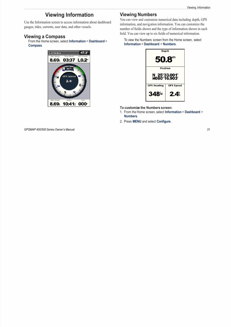
Viewing a Compass From the Home screen, select Information > Dashboard >
Compass.
Viewing NumbersYou can view and customize numerical data including depth, GPS
information, and navigation information. You can customize the
number of elds shown and the type of information shown in each
eld. You can view up to six elds of numerical information.
To view the Numbers screen from the Home screen, selectInformation > Dashboard > Numbers.
To customize the Numbers screen:
1. From the Home screen, select Information > Dashboard >
Numbers.2. Press MENU and select Confgure.
Viewing Information
3 S l h b f ld h (3 4 6) Vi i T i I f i
8/12/2019 garmin 421s manual
http://slidepdf.com/reader/full/garmin-421s-manual 38/84
32 GPSMAP 400/500 Series Owner’s Manua
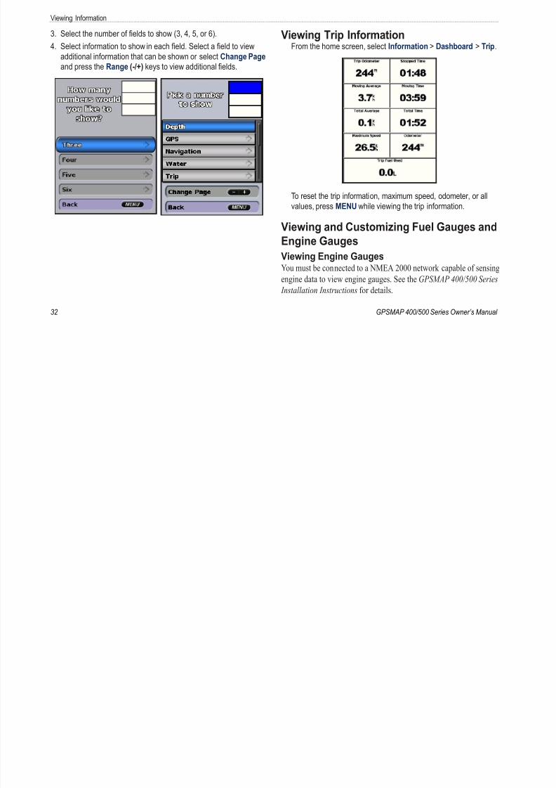
3. Select the number of elds to show (3, 4, 5, or 6).
4. Select information to show in each eld. Select a eld to view
additional information that can be shown or select Change Page
and press the Range (-/+) keys to view additional elds.
Viewing Trip Information From the home screen, select Information > Dashboard > Trip
To reset the trip information, maximum speed, odometer, or all
values, press MENU while viewing the trip information.
Viewing and Customizing Fuel Gauges and
Engine Gauges
Viewing Engine GaugesYou must be connected to a NMEA 2000 network capable of sensin
engine data to view engine gauges. See the GPSMAP 400/500 Serie Installation Instructions for details.
Viewing Informa
F th H l t I f ti D hb d 2 S l t
8/12/2019 garmin 421s manual
http://slidepdf.com/reader/full/garmin-421s-manual 39/84
GPSMAP 400/500 Series Owner’s Manual
From the Home screen, select Information > Dashboard >
Engine.
Cycling Through Engine Gauge Screens
1. From the Home screen, select Information > Dashboard >
Engine.
2. Select the left and right arrows on the Rocker to move from one
gauge screen to the next.
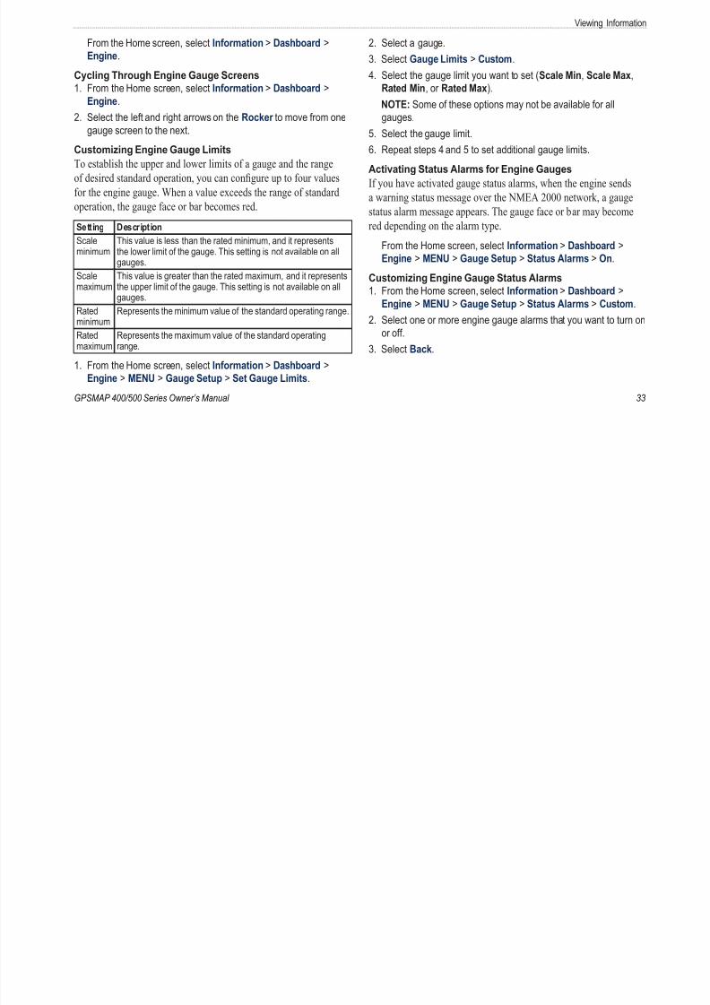
Customizing Engine Gauge Limits
To establish the upper and lower limits of a gauge and the range
of desired standard operation, you can congure up to four values
for the engine gauge. When a value exceeds the range of standard
operation, the gauge face or bar becomes red.
Setting Description
Scaleminimum
This value is less than the rated minimum, and it representsthe lower limit of the gauge. This setting is not available on allgauges.
Scalemaximum
This value is greater than the rated maximum, and it representsthe upper limit of the gauge. This setting is not available on allgauges.
Ratedminimum
Represents the minimum value of the standard operating range.
Ratedmaximum
Represents the maximum value of the standard operatingrange.
1. From the Home screen, select Information > Dashboard >
Engine > MENU > Gauge Setup > Set Gauge Limits.
2. Select a gauge.
3. Select Gauge Limits > Custom.
4. Select the gauge limit you want to set (Scale Min, Scale Max,
Rated Min, or Rated Max).
NOTE: Some of these options may not be available for all
gauges.
5. Select the gauge limit.
6. Repeat steps 4 and 5 to set additional gauge limits.
Activating Status Alarms for Engine Gauges
If you have activated gauge status alarms, when the engine sends
a warning status message over the NMEA 2000 network, a gauge
status alarm message appears. The gauge face or bar may become
red depending on the alarm type.
From the Home screen, select Information > Dashboard >Engine > MENU > Gauge Setup > Status Alarms > On.
Customizing Engine Gauge Status Alarms
1. From the Home screen, select Information > Dashboard >
Engine > MENU > Gauge Setup > Status Alarms > Custom
2. Select one or more engine gauge alarms that you want to turn
or off.
3. Select Back.
Viewing Information
Selecting the Number of Engines Shown in Gauges 4 Repeat step 3 for the second third and fourth engine bar as
8/12/2019 garmin 421s manual
http://slidepdf.com/reader/full/garmin-421s-manual 40/84
34 GPSMAP 400/500 Series Owner’s Manua
Selecting the Number of Engines Shown in Gauges
The engine gauges can show information for up to four engines.
1. From the Home screen, select Information > Dashboard >
Engine > MENU > Gauge Setup > Engine Selection > Num.
Engines.
2. Select the number of engines.
3. Select Back.
To select the engines for which information appears in the gauges,
select Edit Engines and complete steps 2 through 5 of “Selecting
the Engines Shown in Gauges” (following section).
Selecting the Engines Shown in Gauges
You must manually select the number of engines shown in the
engine gauges ( page 34) before you can select the engines for which
information appears in the gauges.
1. From the Home screen, select Information > Dashboard >
Engine > MENU > Gauge Setup > Engine Selection > Edit
Engines.
2. Select First Engine.
3. Select the number of the engine for which you want to view
information in the rst gauge or bar.
For example, if you select “3,” the rst engine bar showsinformation for the engine identied as “Engine3” on the NMEA
2000 network.
4. Repeat step 3 for the second, third, and fourth engine bar, as
needed.
5. Select Back.
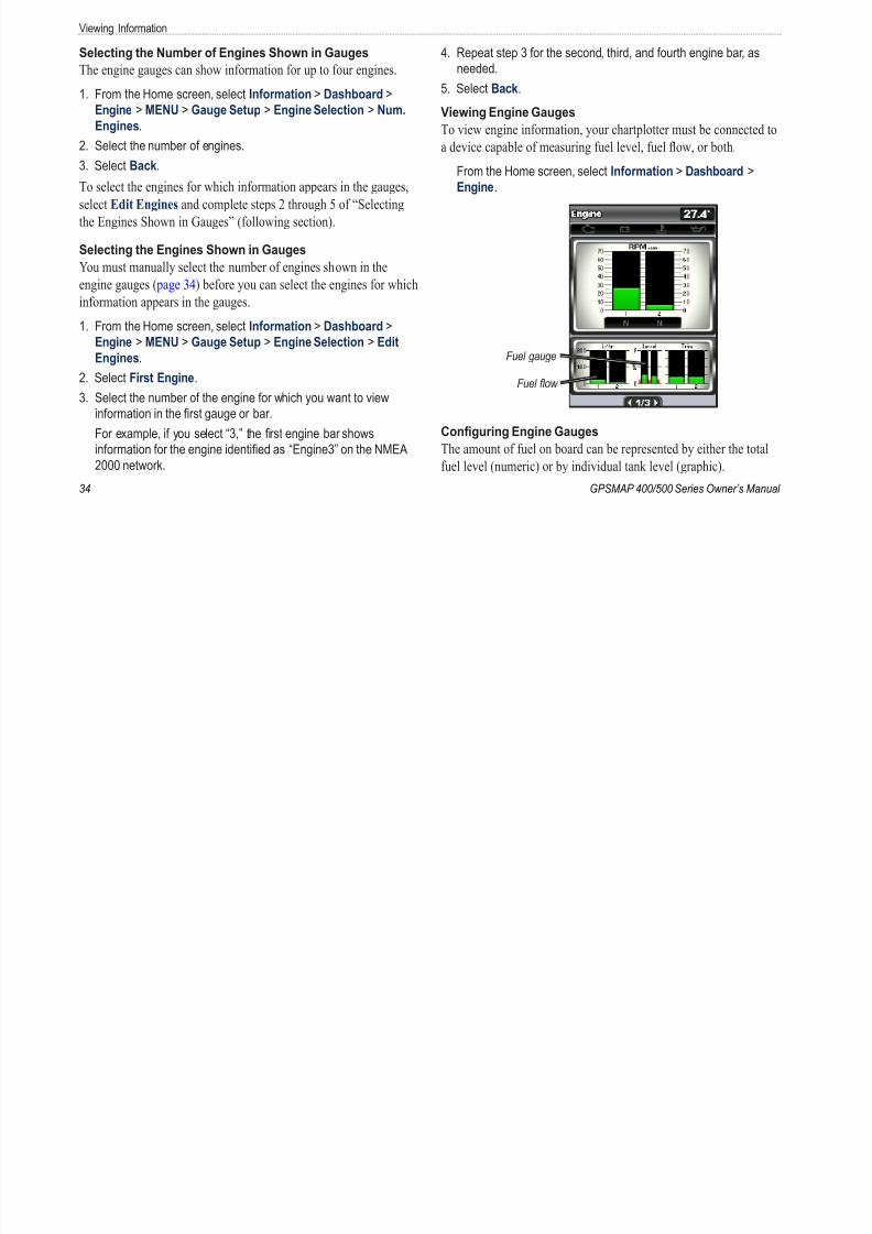
Viewing Engine Gauges
To view engine information, your chartplotter must be connected to
a device capable of measuring fuel level, fuel ow, or both.
From the Home screen, select Information > Dashboard >
Engine.
Fuel gauge
Fuel fow
Conguring Engine Gauges
The amount of fuel on board can be represented by either the total
fuel level (numeric) or by individual tank level (graphic).
Viewing Informa
From the Home screen select Information > Dashboard > Synchronizing Fuel Gauge Readings with Fuel Levels

8/12/2019 garmin 421s manual
http://slidepdf.com/reader/full/garmin-421s-manual 41/84
GPSMAP 400/500 Series Owner’s Manual
From the Home screen, select Information > Dashboard >
Engine > MENU > Gauge Setup > Fuel Display.
Use Total Fuel Level—select to display a numeric value for
the total fuel level.
Use Fuel Tank Levels > Num. Tanks—select to display a
graphical representation of all the specied tanks.
Viewing Fuel Gauges
To view engine information, your chartplotter must be connected to
a device capable of measuring fuel level, fuel ow, or both.
From the Home screen, select Information > Dashboard >
Engine.
•
•
Synchronizing Fuel Gauge Readings with Fuel Levels
From the Home screen, select Information > Dashboard > F
(or Engine) > MENU.
Fill Up All Tanks—select when your tanks are full. The fue
level is reset to maximum capacity. Adjust if necessary.
Add Fuel To Boat—select when you have added less than
a full tank. Enter the amount of fuel added. Select Done. Aestimate of the fuel added appears. Adjust if necessary.
Set Total Fuel Onboard—select to specify the total fuel in
your tanks. Select Done.
•
•
•
Viewing Information
Viewing and Customizing Wind Gauges Selecting True Apparent or Ground Wind for the
8/12/2019 garmin 421s manual
http://slidepdf.com/reader/full/garmin-421s-manual 42/84
36 GPSMAP 400/500 Series Owner’s Manua
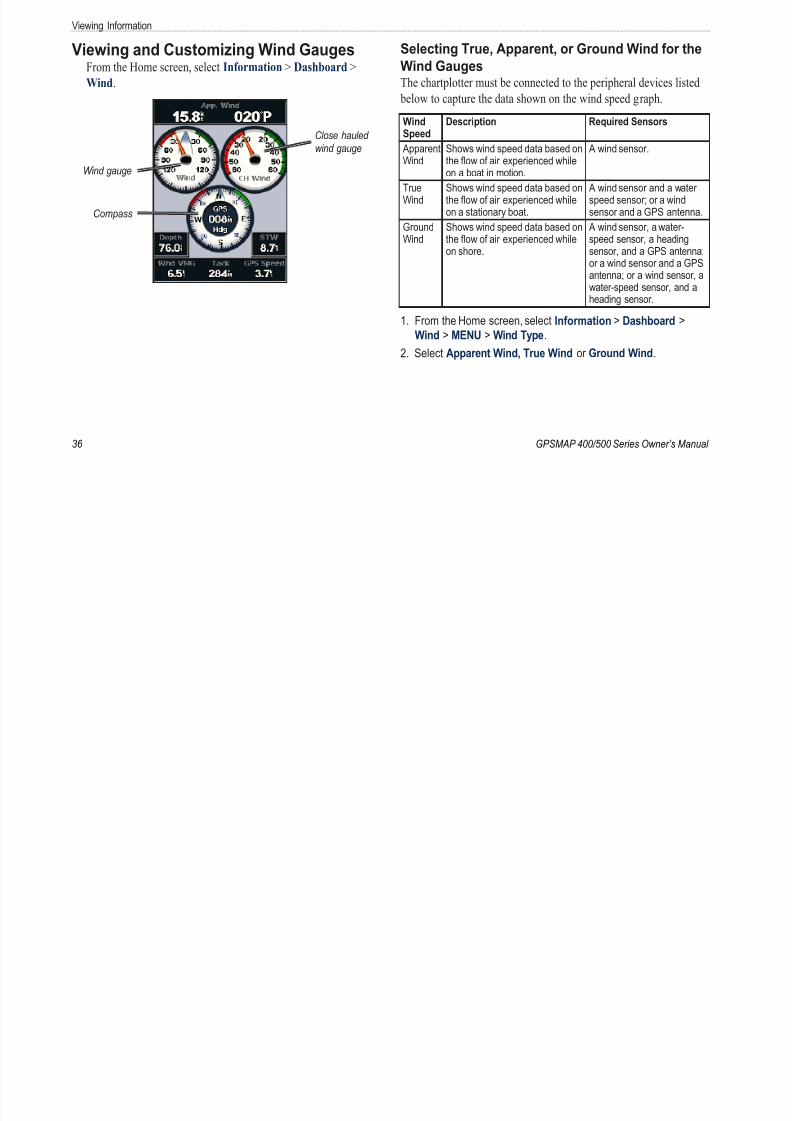
Viewing and Customizing Wind GaugesFrom the Home screen, select Information > Dashboard >
Wind.
Wind gauge
Compass
Close hauled
wind gauge
Selecting True, Apparent, or Ground Wind for the
Wind GaugesThe chartplotter must be connected to the peripheral devices listed
below to capture the data shown on the wind speed graph.
WindSpeed
Description Required Sensors
ApparentWind
Shows wind speed data based onthe ow of air experienced whileon a boat in motion.
A wind sensor.
TrueWind
Shows wind speed data based onthe ow of air experienced whileon a stationary boat.
A wind sensor and a waterspeed sensor; or a windsensor and a GPS antenna.
GroundWind
Shows wind speed data based onthe ow of air experienced whileon shore.
A wind sensor, a water-speed sensor, a headingsensor, and a GPS antenna;or a wind sensor and a GPSantenna; or a wind sensor, awater-speed sensor, and aheading sensor.
1. From the Home screen, select Information > Dashboard >
Wind > MENU > Wind Type.
2. Select Apparent Wind, True Wind or Ground Wind.

8/12/2019 garmin 421s manual
http://slidepdf.com/reader/full/garmin-421s-manual 43/84
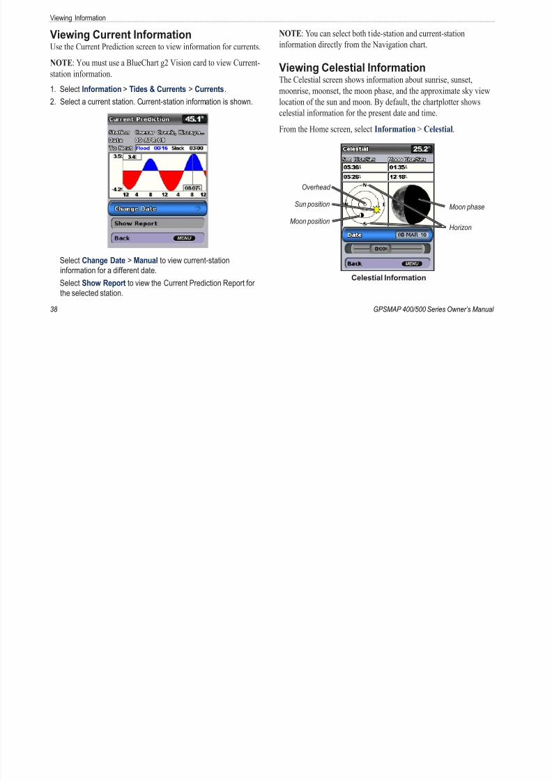
8/12/2019 garmin 421s manual
http://slidepdf.com/reader/full/garmin-421s-manual 44/84
Viewing Informa
Viewing Celestial Information for a Different Date 2. Check your MapSource version on the computer by clicking
8/12/2019 garmin 421s manual
http://slidepdf.com/reader/full/garmin-421s-manual 45/84
GPSMAP 400/500 Series Owner’s Manual
Viewing Celestial Information for a Different DateYou can select a date and time for which to view celestial
information, and you can view the moon phase for the selected date
and time.
1. From the Home screen, select Information > Celestial > Date.
2. Change the date to view celestial information for a different date.
Viewing User Data To view user data, from the Home screen, select Information >
User Data.
Waypoints —view a list of all saved waypoints ( page 14).
Routes —view a list of saved routes ( page 26).
Tracks —view a list of saved tracks ( page 28).
Data Transfer —transfer waypoints, routes, and tracks to and from
an SD card or a network.
Clear User Data —erase all user waypoints, routes, and tracks.
To copy or merge MapSource data to your chartplotter:
1. Insert an SD card into your chartplotter to allow it to place a le
on the SD card. This le provides information to MapSource
to format the data. This only needs to be done the rst time
you copy or merge MapSource data to your chartplotter from a
specic SD card.
2. Check your MapSource version on the computer by clicking
Help > About MapSource. If the version is older than 6.12.2,
update to the most-current version by clicking Help > Check f
Software Updates, or check the Garmin Web site at
www.garmin.com.
3. Insert the SD card into an SD card reader that is attached to th
computer.4. From within MapSource, click Transfer > Send to Device.
5. From the Send to Device window, select the drive for the SD
card reader and the types of data you want to copy to your
chartplotter.
6. Click Send.
7. Insert the SD card into the SD card slot on the front of the unit
8. From the Home screen on your chartplotter, select Informatio
User Data > Data Transfer .9. Complete one of the following:
Select Merge From Card to transfer data from the SD card
the chartplotter and combine it with existing user data.
Select Replace From Card to overwrite the data on your
chartplotter.
10. Select the le name from the list. The data is transferred from
SD card to the chartplotter.
•
•
Viewing Information
To transfer data (waypoints, routes, tracks) to an SD card: To copy the built-in maps to an SD card:
8/12/2019 garmin 421s manual
http://slidepdf.com/reader/full/garmin-421s-manual 46/84
40 GPSMAP 400/500 Series Owner’s Manua
( yp , , )
1. Insert an SD card into the SD card slot on the front of the unit.
2. From the Home screen, select Information > User Data > Data
Transfer > Save To Card.
3. Complete one of the following:
Select the le name from the list.
Select Add New File to create a new le. Enter the le name
using the Rocker, and select Done.
4. Select Yes to save waypoints, routes, and tracks to the SD card.
The le name is saved with an .ADM extension.
To transfer data (waypoints, routes, tracks) from an SDtransfer data (waypoints, routes, tracks) from an SD
card:
1. Insert an SD card into the SD card slot on the front of the unit.
2. From the Home screen, select Information > User Data > Data
Transfer .
3. Complete one of the following:
Select Merge From Card to transfer data from the SD card to
the chartplotter and combine it with existing user data.
Select Replace From Card to overwrite items on your
chartplotter.
4. Select the le name from the list. The data is transferred from the
SD card to the chartplotter.
•
•
•
•
py p
1. Insert an SD card (at least 4 GB) into the SD card slot on the
front of the unit.
2. From the Home screen, select Information > User Data > Data
Transfer > Copy Built-In Map to copy the maps loaded onto
your chartplotter to the SD card.
To transfer data to or from a NMEA 2000 network:1. Connect the unit to a NMEA 2000 network. (Refer to the
GPSMAP 400/500 Installation Instructions.)
2. From the Home screen, select Information > User Data > Data
Transfer > Network.
3. Complete one of the following:
Select Clone User Data to transfer waypoints, routes,
and tracks to other chartplotters connected to the network.
Existing data is overwritten on those chartplotters.Select Merge User Data to transfer data between all the
chartplotters connected to the network. Unique data is
combined with existing data on every chartplotter.
To back up data to a computer:
1. Insert an SD card into the SD card slot on the front of the unit.
2. From the Home screen, select Information > User Data > Data
Transfer > Save To Card.
•
•
Viewing Informa
3. Complete one of the following: Viewing Other Vessels
8/12/2019 garmin 421s manual
http://slidepdf.com/reader/full/garmin-421s-manual 47/84
GPSMAP 400/500 Series Owner’s Manual
p g
Select the le name from the list.
Select Add New File to create a new le. Enter the le name
using the Rocker , and press Select.
4. Remove the SD card from the unit, and insert it into an SD card
reader attached to a computer.
5. From Windows® Explorer, open the Garmin\UserData folder on
the SD card.
6. Copy the appropriate .ADM le on the card, and paste it to any
location on the computer.
To restore backup data to your chartplotter:
1. Copy the appropriate .ADM le from the computer to an SD card
in the Garmin\UserData folder.
2. Insert the SD card into your chartplotter.
3. From the Home screen on your chartplotter, select Information >
User Data > Data Transfer > Replace From Card.
To delete all waypoints, routes, and tracks:
1. From the Home screen on your chartplotter, select Information >
User Data > Clear User Data.
2. Select Waypoints, Routes, Saved Tracks, or All.
3. Select OK to delete the data.
•
•
Viewing Other Vessels To view information about other boats from the Home screen,
select Information > Other Vessels.
NOTE: To view information about other boats, your unit must
connected to an external AIS (Automatic Identication System
or DSC (Digital Selective Calling) device. See page 61 for mo
information.
AIS List —see page 46.
DSC List —view the 100 most-recent calls. The DSC List shows
most-recent call from a boat. If a second call is received from the
same boat, it replaces the rst call in the list.
Select Options to sort calls by name, type, MMSI, distance fro
your boat, or the time the call was received.
Select Options > Delete All to delete all the calls from the list
To add a DSC contact:
1. Select Add Contact.
2. Use the Rocker to enter the MMSI number of the vessel.
3. Use the Rocker to enter the name of the vessel.
Automatic Identication SystemThe Automatic Identication System (AIS) enables you to identif
and track other vessels.
Viewing Information
About AIS AIS Targeting Symbols
8/12/2019 garmin 421s manual
http://slidepdf.com/reader/full/garmin-421s-manual 48/84
42 GPSMAP 400/500 Series Owner’s Manua
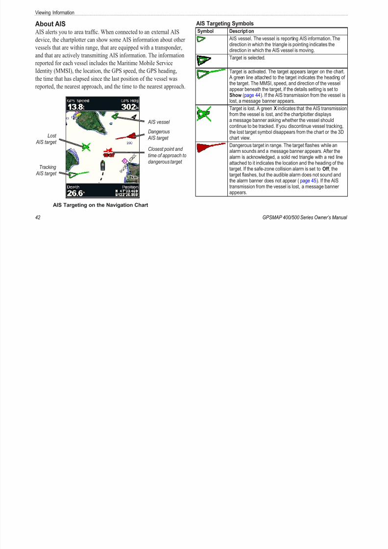
AIS alerts you to area trafc. When connected to an external AIS
device, the chartplotter can show some AIS information about other
vessels that are within range, that are equipped with a transponder,
and that are actively transmitting AIS information. The information
reported for each vessel includes the Maritime Mobile Service
Identity (MMSI), the location, the GPS speed, the GPS heading,the time that has elapsed since the last position of the vessel was
reported, the nearest approach, and the time to the nearest approach.
AIS vessel
AIS Targeting on the Navigation Chart
Dangerous AIS target Lost AIS target
Closest point and
time of approach to
dangerous target Tracking
AIS target
Symbol Description
AIS vessel. The vessel is reporting AIS information. Thedirection in which the triangle is pointing indicates thedirection in which the AIS vessel is moving.
Target is selected.
Target is activated. The target appears larger on the chart. A green line attached to the target indicates the heading ofthe target. The MMSI, speed, and direction of the vesselappear beneath the target, if the details setting is set toShow (page 44). If the AIS transmission from the vessel islost, a message banner appears.
Target is lost. A green X indicates that the AIS transmissionfrom the vessel is lost, and the chartplotter displaysa message banner asking whether the vessel shouldcontinue to be tracked. If you discontinue vessel tracking,
the lost target symbol disappears from the chart or the 3Dchart view.
Dangerous target in range. The target ashes while analarm sounds and a message banner appears. After thealarm is acknowledged, a solid red triangle with a red lineattached to it indicates the location and the heading of thetarget. If the safe-zone collision alarm is set to Off , thetarget ashes, but the audible alarm does not sound andthe alarm banner does not appear (page 45). If the AIStransmission from the vessel is lost, a message bannerappears.
Viewing Informa
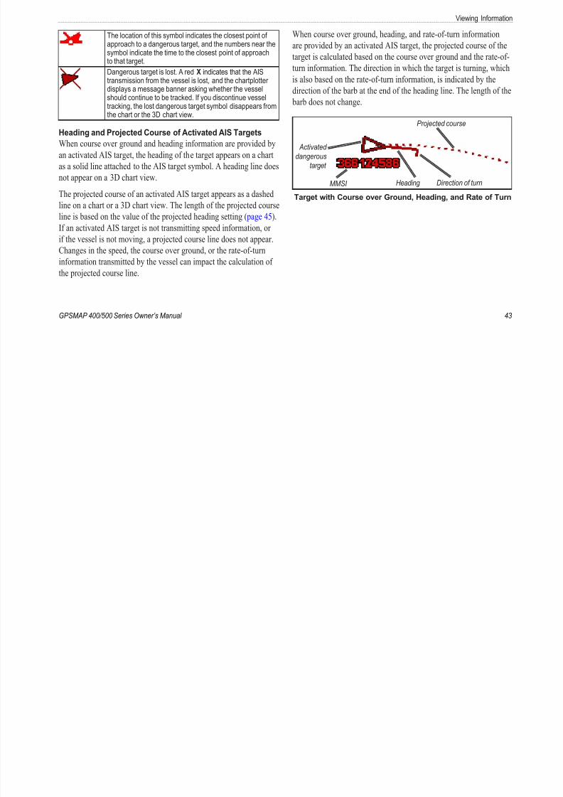
The location of this symbol indicates the closest point of When course over ground, heading, and rate-of-turn information
8/12/2019 garmin 421s manual
http://slidepdf.com/reader/full/garmin-421s-manual 49/84
GPSMAP 400/500 Series Owner’s Manual
approach to a dangerous target, and the numbers near thesymbol indicate the time to the closest point of approachto that target.
Dangerous target is lost. A red X indicates that the AIStransmission from the vessel is lost, and the chartplotterdisplays a message banner asking whether the vesselshould continue to be tracked. If you discontinue vesseltracking, the lost dangerous target symbol disappears fromthe chart or the 3D chart view.
Heading and Projected Course of Activated AIS Targets
When course over ground and heading information are provided by
an activated AIS target, the heading of the target appears on a chart
as a solid line attached to the AIS target symbol. A heading line does
not appear on a 3D chart view.
The projected course of an activated AIS target appears as a dashedline on a chart or a 3D chart view. The length of the projected course
line is based on the value of the projected heading setting ( page 45).
If an activated AIS target is not transmitting speed information, or
if the vessel is not moving, a projected course line does not appear.
Changes in the speed, the course over ground, or the rate-of-turn
information transmitted by the vessel can impact the calculation of
the projected course line.
are provided by an activated AIS target, the projected course of th
target is calculated based on the course over ground and the rate-o
turn information. The direction in which the target is turning, whi
is also based on the rate-of-turn information, is indicated by the
direction of the barb at the end of the heading line. The length of t
barb does not change.
MMSI Heading Direction of turn
Projected course
Activated
dangerous
target
Target with Course over Ground, Heading, and Rate of Tu
Viewing Information
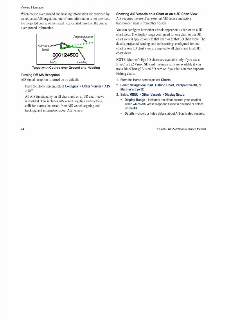
When course over ground and heading information are provided by Showing AIS Vessels on a Chart or on a 3D Chart View
8/12/2019 garmin 421s manual
http://slidepdf.com/reader/full/garmin-421s-manual 50/84
44 GPSMAP 400/500 Series Owner’s Manua
an activated AIS target, but rate-of-turn information is not provided,
the projected course of the target is calculated based on the course
over ground information.
MMSI Heading
Projected course
Activated
target
Target with Course over Ground and Heading
Turning Off AIS Reception
AIS signal reception is turned on by default.
From the Home screen, select Confgure > Other Vessels > AIS
> Off .
All AIS functionality on all charts and on all 3D chart views
is disabled. This includes AIS vessel targeting and tracking,
collision alarms that result from AIS vessel targeting and
tracking, and information about AIS vessels.
AIS requires the use of an external AIS device and active
transponder signals from other vessels.
You can congure how other vessels appear on a chart or on a 3D
chart view. The display range congured for one chart or one 3D
chart view is applied only to that chart or to that 3D chart view. The
details, projected heading, and trails settings congured for one
chart or one 3D chart view are applied to all charts and to all 3D
chart views.
NOTE: Mariner’s Eye 3D charts are available only if you use a
BlueChart g2 Vision SD card. Fishing charts are available if you
use a BlueChart g2 Vision SD card or if your built-in map supports
Fishing charts.
1. From the Home screen, select Charts.2. Select Navigation Chart, Fishing Chart, Perspective 3D, or
Mariner’s Eye 3D.
3. Select MENU > Other Vessels > Display Setup.
Display Range—indicates the distance from your location
within which AIS vessels appear. Select a distance or select
Show All.
Details—shows or hides details about AIS-activated vessels.
•
•
Viewing Informa
Proj. Heading—allows you to enter the projected heading
ti f AIS ti t d l
• 4. Select AIS Vessel.
8/12/2019 garmin 421s manual
http://slidepdf.com/reader/full/garmin-421s-manual 51/84
GPSMAP 400/500 Series Owner’s Manual
time for AIS-activated vessels.
Trails—shows the tracks of AIS vessels. Select the length of
the track that appears using a trail.
Activating a Target for an AIS Vessel
NOTE: Mariner’s Eye 3D charts are available only if you use a
BlueChart g2 Vision SD card. Fishing charts are available if youuse a BlueChart g2 Vision SD card or if your built-in map supports
Fishing charts.
1. From the Home screen, select Charts.
2. Select Navigation Chart, Fishing Chart, Perspective 3D, or
Mariner’s Eye 3D.
3. Use the Rocker to select an AIS vessel. Press SELECT.
4. Select AIS Vessel > Activate Target.Viewing Information about a Targeted AIS Vessel
You can view the AIS signal status, MMSI, GPS speed, GPS
heading, and other information that is reported about a targeted AIS
vessel.
1. From the Home screen, select Charts.
2. Select Navigation Chart, Fishing Chart, Perspective 3D, or
Mariner’s Eye 3D.
3. Use the Rocker to select an AIS vessel. Press SELECT.
•Deactivating a Target for an AIS Vessel
NOTE: Mariner’s Eye 3D charts are available only if you use a
BlueChart g2 Vision SD card. Fishing charts are available if you
use a BlueChart g2 Vision SD card or if your built-in map suppor
Fishing charts.
1. From the Home screen, select Charts.
2. Select Navigation Chart, Fishing Chart, Perspective 3D, or
Mariner’s Eye 3D.
3. Use the Rocker to select an AIS vessel. Press SELECT.
4. Select AIS Vessel > Deactivate.
Setting the Safe-zone Collision Alarm
The safe-zone collision alarm is used only with AIS. The safe zon
is used for collision avoidance, and can be customized. All safe-zcollision alarm settings are applied to all charts and to all 3D char
views.
1. From the Home screen, select Charts.
2. Select Navigation Chart, Fishing Chart, Perspective 3D, or
Mariner’s Eye 3D.
Viewing Information
3. Select MENU > Other Vessels > AIS Alarm > On. The AIS target list shows information about all of the boats your
i i i i Th AIS li h h MMSI (if h b i
8/12/2019 garmin 421s manual
http://slidepdf.com/reader/full/garmin-421s-manual 52/84
46 GPSMAP 400/500 Series Owner’s Manua
A message banner appears and an alarm sounds when an AIS-
activated vessel enters the safe-zone ring around your boat. The
object is also labeled as dangerous on the screen. The Off setting
disables the message banner and the audible alarm, but the object
is still labeled as dangerous on the screen.
4. Select Range to set the measured radius of the safe-zone ring toa specied distance from 500 ft. to 2.0 nm (or from 150 m to 3.0
km, or from 500 ft. to 2.0 mi.).
5. Select a distance.
6. Select Time To to sound an alarm if AIS determines that a
target will intersect the safe zone within the dened time interval
(ranging from 1 to 24 minutes).
7. Select a time.
Viewing a List of AIS Targets
NOTE: Mariner’s Eye 3D charts and Fish Eye 3D charts are
available only if you use a BlueChart g2 Vision SD card. Fishing
charts are available if you use a BlueChart g2 Vision SD card or if
your built-in map supports Fishing charts.
unit is monitoring. The AIS list shows the MMSIs or (if the boat is
broadcasting it) names of the AIS boats and is sorted by range. The
boat nearest to your boat appears at the top of the list.
1. From the Home screen, select Charts.
2. Select Navigation Chart, Fishing Chart, Perspective 3D, or
Mariner’s Eye 3D.
3. Select MENU > Other Vessels > AIS List.
Making a Call to an AIS Target
See “Calling an AIS Target” ( page 65).
Conguring the Chartplo
Conguring the Chartplotter Speed Filter —select On, Off , or Auto. The speed lter avera
th d f b t h t i d f ti f th
•
8/12/2019 garmin 421s manual
http://slidepdf.com/reader/full/garmin-421s-manual 53/84
GPSMAP 400/500 Series Owner’s Manual
Use the Congure screen to congure unit settings.
Conguring System Settings To change general system settings from the Home screen, select
Confgure > System.Simulator —turn Simulator mode on or off. Select Setup to set
simulator options, such as simulated position, speed, and direction.
Beeper/Display —select Beeper to set when the unit makes audible
sounds. Select Display > Backlight to brighten or darken the
backlight. Select Display > Color Mode to switch between Day
mode and Night mode ( page 4).
Auto Power —turn Auto Power On or Off . When On is selected, thechartplotter will automatically turn on whenever power is applied,
unless the chartplotter is turned off with the Power Key before
power is lost.
GPS —view GPS satellites.
Skyview —view the GPS satellite constellation.
WAAS/EGNOS —toggle WAAS (in North America) or EGNOS
(in Europe) on or off. WAAS/EGNOS can provide more-accurate
GPS position information. However, when using WAAS or
EGNOS, the device takes longer to acquire satellites.
•
•
•
the speed of your boat over a short period of time for smoother
speed values.
System Information —view system information and reset factory
settings. The Save to Card button is provided as a troubleshootin
tool. A Garmin Product Support representative may ask you to us
this feature to retrieve data about your chartplotter.
Event Log —displays a list of system events. Select an event to v
additional information.
Conguring Units of Measure To change units of measure from the Home screen, select
Confgure > Preferences > Units.
System Units —a global setting that denes individual units ofmeasure at the same time: Statute (mh, ft, ºF), Metric (kh, m, ºC
Nautical (kt, ft, ºF), or Custom. Select Custom to individually
dene units of measure for depth, temperature, distance, speed,
elevation, volume, and pressure.
NOTE: You must be receiving NMEA sonar depth data to view
depth and water temperature information.
Conguring the Chartplotter
Heading —sets the reference used in calculating heading
information
DST (Daylight Saving Time)—select Off , On, or Auto. The
auto setting automatically turns daylight saving time on or off
•

8/12/2019 garmin 421s manual
http://slidepdf.com/reader/full/garmin-421s-manual 54/84
48 GPSMAP 400/500 Series Owner’s Manua
information.
Auto Magnetic —automatically sets the magnetic declination for
your location.
True —sets true north as the heading reference.
Grid —sets grid north as the heading reference (000º).User Magnetic —allows you to set the magnetic variation value.
Position Format —change the coordinate style in which a given
location reading appears. Do not change the position format unless
you are using a map or chart that species a different position
format.
Map Datum —change the coordinate system in which the map is
structured. Do not change the map datum unless you are using a map
or chart that species a different map datum.
Time —set the time options.
Time Format —select 12-hour, 24-hour, or UTC time format.
Time Zone —set the time zone you want displayed for time
readings. If Auto is selected for the Time Zone, the DST option
is not available and is automatically set to Auto.
•
•
•
•
•
•
auto setting automatically turns daylight saving time on or off,
depending on the time of year.
Baro. Ref. Time —specify the reference time (from 30 minutes
to 24 hours) used to calculate the barometric pressure trend.
The trend is displayed on the wind gauge when ground wind is
selected ( page 36) or on the Cruising data bar ( page 9).
Changing the System Language To change the system language, from the Home screen, select
Confgure > Preferences > Language. Select the language.
Conguring Navigation Preferences To change navigation preferences, from the Home screen, selec
Confgure > Preferences > Navigation.
Route Labels —for saved routes, this determines whether route
turns are indicated by number (Turn 1, Turn 2, and so on) or by
waypoint name, or whether the description of turns is hidden.
Turn Transition —set how much time or how far before a turn in a
route that you transition to the next leg.
Speed Sources —specify the sensor used for wind numbers and fuel
economy. Select Wind or Fuel Economy to toggle between water
(from a water-speed sensor) and GPS (from the calculated GPS
speed).
•
Conguring the Chartplo
Auto Guidance —set the automatic guidance parameters: To set the distance from shore:
1 Dock your boat or drop anchor
8/12/2019 garmin 421s manual
http://slidepdf.com/reader/full/garmin-421s-manual 55/84
GPSMAP 400/500 Series Owner’s Manual
Safe Depth —set the minimum depth (chart depth datum) to
allow when calculating an automatic guidance path. A safe depth
of less than one meter is not allowed when using automatic
guidance.
Safe Height —set the minimum height (chart height datum) of a
bridge that your boat can safely travel under.
Shoreline Distance —set the safe distance for your boat from the
shore: Nearest, Near, Normal, Far, or Farthest.
Shoreline Distance Auto Guidance SettingThe Shoreline Distance setting indicates how close to the shore you
want the auto-guidance line to be placed. The auto-guidance line
may move if you change this setting while navigating.
The available values for the Shoreline Distance setting (Nearest,
Near, Normal, Far, or Farthest) are relative, not absolute. To
ensure that the auto-guidance line is placed an appropriate distance
from shore, you can assess the placement of the auto-guidance line
using one or more familiar destinations that require navigation
through a narrow waterway.
•
•
•
1. Dock your boat or drop anchor.
2. From the Home screen, select Confgure > Preferences >
Navigation > Auto Guidance > Shoreline Dist. > Normal.
3. From Home screen, select Where To? > Waypoints.
4. Select a waypoint for a destination that you have navigated to
previously.5. Select Navigate To > Guide To.
6. Review the placement of the Auto Guidance line. Determine
whether the line safely avoids known obstacles, and whether t
turns enable efcient travel.
7. Complete an action:
If the placement of the Auto Guidance line is satisfactory,
select MENU > Navigation Options > Stop Navigation.
Proceed to step 11.If the Auto Guidance line is too close to known obstacles,
from the Home screen, select Confgure > Preferences >
Navigation > Auto Guidance > Shoreline Distance > Fa
If the turns in the Auto Guidance line are too wide, from the
Home screen, select Confgure > Preferences > Navigati
> Auto Guidance > Shoreline Distance > Near .
•
•
•
Conguring the Chartplotter
8. If you selected Near or Far in step 7, review the placement of
the Auto Guidance line Determine whether the line safely avoidsConguring Communications Settings
To change the communications settings from the Home screen

8/12/2019 garmin 421s manual
http://slidepdf.com/reader/full/garmin-421s-manual 56/84
50 GPSMAP 400/500 Series Owner’s Manua
the Auto Guidance line. Determine whether the line safely avoids
known obstacles, and whether the turns enable efcient travel.
9. Complete an action:
If the placement of the Auto Guidance line is satisfactory,
select MENU > Navigation Options > Stop Navigation.
Proceed to step 11.If the Auto Guidance line is too close to known obstacles,
from the Home screen, select Confgure > Preferences
> Navigation > Auto Guidance > Shoreline Distance >
Farthest.
If the turns in the Auto Guidance line are too wide, from the
Home screen, select Confgure > Preferences > Navigation
> Auto Guidance > Shoreline Distance > Nearest.
10. If you selected Nearest or Farthest in step 9, review the
placement of the Auto Guidance line. Determine whether the line
safely avoids known obstacles, and whether the turns enable
efcient travel.
11. Repeat steps 1-10 at least once more, using a different
destination each time, until you are familiar with the functionality
of the Shoreline Distance setting.
•
•
•
To change the communications settings from the Home screen,
select Confgure > Communications.
Serial Port 1 —congures the input/output format for serial port 1 t
use when connecting your chartplotter to external NMEA devices, a
computer, or other Garmin devices.
Garmin Data Transfer —supports the input or output of
Garmin-proprietary data for communicating with Garmin
software.
NMEA Standard —supports the input or output of standard
NMEA 0183 data, DSC, and sonar NMEA input support for the
DPT, MTW, and VHW sentences.
NMEA High Speed —supports the input or output of standard
0183 data for most AIS receivers.Serial Port 2 (if supported)—congures the input/output format for
serial port 2 to use when connecting your chartplotter to external
NMEA devices, a computer, or other Garmin devices.
NMEA 0183 Setup —enable or disable NMEA 0183 output
sentences for sounder, route, system, and Garmin NMEA settings.
To enable or disable NMEA 0183 output sentences:
1. From the Home screen, select Confgure > Communications >NMEA 0183 Setup.
•
•
•
Conguring the Chartplo
2. Select a setting (Sounder , Route, System, or Garmin).
3 Select the NMEA0183 output sentence to toggle the output on or
To label engines as names:
1. From the Home screen, select Confgure > Communications

8/12/2019 garmin 421s manual
http://slidepdf.com/reader/full/garmin-421s-manual 57/84
GPSMAP 400/500 Series Owner’s Manual
3. Select the NMEA 0183 output sentence to toggle the output on or
off.
Posn. Precision —adjust the number of digits (Two Digits,
Three Digits, or Four Digits) to the right of the decimal point
for transmission of NMEA output.
Waypoint IDs —determine how the unit identies waypointidentiers (Names or Numbers).
Defaults —resets all NMEA 0183 sentences to the default setting.
NMEA 2000 Setup —
Device List —lists the NMEA 2000 devices on your network. If a
NMEA 2000 device has conguration options or settings, select
the device for a list of options.
Label Devices —allows you to name your engines and tanks sothat you can better identify their location on the boat.
To label engines as numbers:
From the Home screen, select Confgure > Communications >
NMEA 2000 Setup > Label Devices > Change Engine Labels
> Use Numbers.
•
•
•
•
•
1. From the Home screen, select Confgure Communications
NMEA 2000 Setup > Label Devices > Change Engine Labe
> Label Type > Choose Names.
2. Select the engine you want to name.
3. Select the location of the engine: Port (P), Center (C),
Starboard (S), Fore (F), or Aft (A).4. Select the label you want to use for the engine.
To label tanks as numbers:
1. From the Home screen, select Confgure > Communications
NMEA 2000 Setup > Label Devices > Change Tank Labels.
2. Select the type of tank you want to label.
3. Select Use Numbers.
To label tanks as names:
1. From the Home screen, select Confgure > Communications
NMEA 2000 Setup > Label Devices > Change Tank Labels.
2. Select the type of tank you want to label.
3. Select Choose Names.
4. Select a tank.
3. Select the location of the tank: Port (P), Center (C), Starboar
(S), Fore (F), or Aft (A).
4. Select the label you want to use for the tank.
Conguring the Chartplotter
Setting AlarmsYou can set the unit to sound an audible alarm when certain
Change Time/Change Distance —if you have Activation set to
Time, select Change Time to set the number of minutes before
•
8/12/2019 garmin 421s manual
http://slidepdf.com/reader/full/garmin-421s-manual 58/84
52 GPSMAP 400/500 Series Owner’s Manua
You can set the unit to sound an audible alarm when certain
conditions are met. By default, all alarms are turned off.
To set an alarm:
1. From the Home screen, select Confgure > Alarms.
2. Select an alarm category.
3. Select an alarm.
4. Select On to turn on the alarm.
5. Specify alarm information.
Setting Navigation Alarms To set a navigation alarm from the Home screen, select
Confgure > Alarms > Navigation.
Arrival —set an alarm to sound when you are within a specied
distance or time from a turn or a destination waypoint.
Type —select whether you want arrival alarms to sound only
when nearing destinations or when nearing either turns or
destinations. Select Off to disable arrival alarms.
Activation —select whether the arrival alarm triggers on time to
arrival or distance to arrival.
•
•
Time, select Change Time to set the number of minutes before
arrival that the alarm should sound. If you have Activation set
to Distance, select Change Distance to set the distance before
arrival that the alarm should sound. Use the Rocker to change
the time or distance.
Anchor Drag —set an alarm to sound when you exceed a specieddrift distance.
Off Course —set an alarm to sound when you are off course by a
specied distance.
Setting System Alarms To set a system alarm from the Home screen, select Confgure
Alarms > System.
Clock —set an alarm using the system (GPS) clock. The unit must be on for the clock alarm to work.
Battery —set an alarm to sound when the battery reaches a specied
low voltage.
GPS Accuracy —set an alarm to sound when the GPS location
accuracy falls outside the specied value.
Conguring the Chartplo
Setting Sonar Alarms To set a sonar alarm from the Home screen, select Confgure >
NOTE: To receive fuel-level information, your unit must be
connected to an external fuel sensor, such as the Garmin GFS 10.
8/12/2019 garmin 421s manual
http://slidepdf.com/reader/full/garmin-421s-manual 59/84
GPSMAP 400/500 Series Owner’s Manual
, g
Alarms > Sonar .
NOTE: To congure sonar alarms, you must be receiving NMEA
sonar depth data.
Shallow Water —set an alarm to sound when the depth is less than
the specied value.
Deep Water —set an alarm to sound when the depth is greater than
the specied value.
Water Temp —set an alarm to sound when the transducer reports
a temperature that is 2°F (1.1°C) above or below the specied
temperature.
Fish —set an alarm to sound when the unit detects a suspended
target of the specied symbols.
—sounds an alarm for all sh sizes.
—sounds an alarm for medium and large sh only.
—sounds an alarm for large sh only.
Setting the Total Fuel Onboard Alarm
You can congure your chartplotter to sound an alarm when the totalamount of remaining onboard fuel reaches the specied level.
,
To enable the Total Fuel Onboard alarm and set the fuel
alarm level:
1. From the Home screen, select Confgure > Alarms > Fuel >
Total Onboard > On (or Off ).
2. If you select On, use the Rocker to indicate the fuel level atwhich the alarm should sound.
Conguring My Boat To congure settings for your boat, from the Home screen, sel
Confgure > My Boat.
Keel Offset —offset the surface reading for the depth of a keel,
making it possible to measure depth from the bottom of the keel
instead of from the transducer location. Enter a positive number tooffset for a keel. Enter a negative number to compensate for a larg
vessel that may draw several feet of water.
To adjust the Keel Offset:
1. From the Home screen, select Confgure > My Boat > Keel
Offset.
Conguring the Chartplotter
2. Use the Rocker to enter the measured distance from the
transducer location to the water line or to the keel of the boat.Calibrate Water Speed —use this menu to calibrate a speed-sensing
device. Follow the on-screen directions for calibration. If you do not

8/12/2019 garmin 421s manual
http://slidepdf.com/reader/full/garmin-421s-manual 60/84
54 GPSMAP 400/500 Series Owner’s Manua
If you are measuring down to the keel (transducer installed at
the water line), enter a (+) positive number. This shows the
depth at the bottom of the keel.
If you are measuring up to the water line (transducer installed
on the bottom of the keel), enter a (-) negative number. Thisshows the depth at the surface.
3. Select Done to accept the number.
A (+) positive number
shows depth at the bottom
of the keel.
Transducer at Surface
A (-) negative number
shows depth at the
surface.
Transducer at the
Bottom of the Keel
Temp Offset —set the temperature offset for the temperature sensor
of your transducer.
•
•
y
have a speed-sensing device, this menu does not appear.
NOTE: If the boat is not moving fast enough or the speed sensor
is not registering a speed, a “Speed Too Low” message appears.
Select OK , and safely increase the speed of the boat. If you get the
message again, stop the boat and make sure the speed-sensor wheelis not stuck. If the wheel turns freely, check the cable connections. I
you continue to get the message, contact Garmin Product Support.
Fuel Capacity —enter the total fuel capacity of your boat.
Conguring Other Vessels To congure settings for boats other than your own, from the
Home screen, select Confgure > Other Vessels.
NOTE: To congure AIS or DSC information for other boats, your
unit must be connected to an external AIS or DSC device.
AIS —turn AIS (Automatic Identication System) on or off. AIS
alerts you to area trafc by providing boat IDs, position, course,
and speed for boats that are within range and equipped with a
transponder.
DSC —turn DSC (Digital Selective Calling) on or off.
Conguring the Chartplo
AIS Alarm —create a safe zone around your boat for collision
avoidance. The zone can be customized.
8/12/2019 garmin 421s manual
http://slidepdf.com/reader/full/garmin-421s-manual 61/84
GPSMAP 400/500 Series Owner’s Manual
To customize safe-zone settings:
From the Home screen, select Confgure > Other Vessels > AIS
Alarm.
Range—change the measured radius of the safe-zone ring to
a specied distance from 500 ft. to 2.0 nm (or from 150 m to3.0 km, or from 500 ft. to 2.0 mi).
Time to (Safe Zone)—sounds an alarm if AIS or MARPA
determines that a target will intersect the safe zone within the
dened time interval (from 1 to 24 minutes).
AIS Alarm—when On is selected, a message is displayed
(“AIS: Dangerous Target”) when a vessel enters the safe
zone. When Off is selected, the message will not be
displayed.
•
•
•
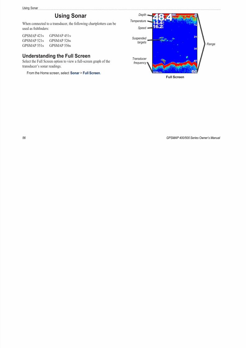
8/12/2019 garmin 421s manual
http://slidepdf.com/reader/full/garmin-421s-manual 62/84
Using So
Understanding the Split Frequency ScreenUse the Split Frequency screen (dual-frequency transducer only)
Understanding The Split Zoom ScreenUse the Split Zoom screen to view the full sonar data from the gra
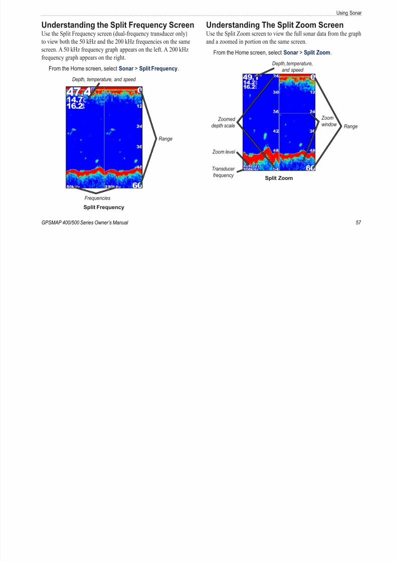
8/12/2019 garmin 421s manual
http://slidepdf.com/reader/full/garmin-421s-manual 63/84
GPSMAP 400/500 Series Owner’s Manual
p q y ( q y y)
to view both the 50 kHz and the 200 kHz frequencies on the same
screen. A 50 kHz frequency graph appears on the left. A 200 kHz
frequency graph appears on the right.
From the Home screen, select Sonar > Split Frequency.
Depth, temperature, and speed
Range
Frequencies
Split Frequency
p g
and a zoomed in portion on the same screen.
From the Home screen, select Sonar > Split Zoom.
Transducer
frequency
Depth, temperature,
and speed
Rang
Zoom
window Zoomed
depth scale
Zoom level
Split Zoom
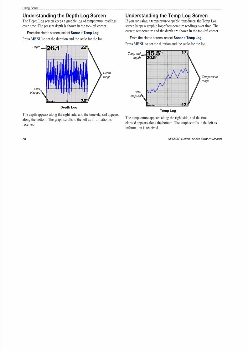
8/12/2019 garmin 421s manual
http://slidepdf.com/reader/full/garmin-421s-manual 64/84
Using So
Setting Up Sonar Use the Sonar Setup screen to dene and adjust settings universal to
Appearance —customize the display of sh symbols, whiteline, a
the sonar color scheme.
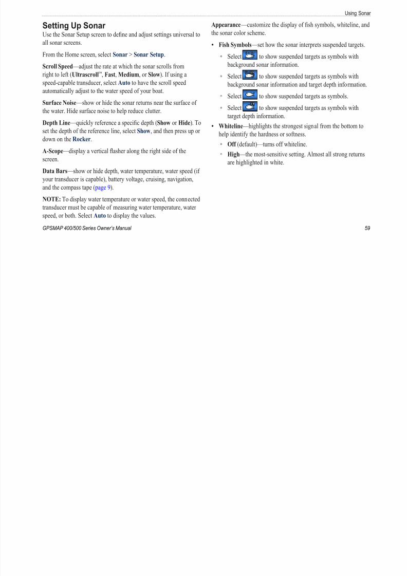
8/12/2019 garmin 421s manual
http://slidepdf.com/reader/full/garmin-421s-manual 65/84
GPSMAP 400/500 Series Owner’s Manual
all sonar screens.
From the Home screen, select Sonar > Sonar Setup.
Scroll Speed —adjust the rate at which the sonar scrolls from
right to left (Ultrascroll™
, Fast, Medium, or Slow). If using aspeed-capable transducer, select Auto to have the scroll speed
automatically adjust to the water speed of your boat.
Surface Noise —show or hide the sonar returns near the surface of
the water. Hide surface noise to help reduce clutter.
Depth Line —quickly reference a specic depth (Show or Hide). To
set the depth of the reference line, select Show, and then press up or
down on the Rocker.
A-Scope —display a vertical asher along the right side of the
screen.
Data Bars —show or hide depth, water temperature, water speed (if
your transducer is capable), battery voltage, cruising, navigation,
and the compass tape ( page 9).
NOTE: To display water temperature or water speed, the connected
transducer must be capable of measuring water temperature, waterspeed, or both. Select Auto to display the values.
Fish Symbols —set how the sonar interprets suspended targets
Select to show suspended targets as symbols with
background sonar information.
Select to show suspended targets as symbols with background sonar information and target depth information
Select to show suspended targets as symbols.
Select to show suspended targets as symbols with
target depth information.
Whiteline —highlights the strongest signal from the bottom to
help identify the hardness or softness.
Off (default)—turns off whiteline.
High —the most-sensitive setting. Almost all strong return
are highlighted in white.
•
◦
◦
◦
◦
•
◦
◦
Using Sonar
Medium —many strong returns are highlighted in white.
Low —the least-sensitive setting. Only the strongest returns
◦
◦
Frequency —when using a dual frequency transducer, select how
the frequencies appear on-screen (200kHz, 50kHz, Dual, or Auto).

8/12/2019 garmin 421s manual
http://slidepdf.com/reader/full/garmin-421s-manual 66/84
60 GPSMAP 400/500 Series Owner’s Manua
are highlighted in white.
Color Scheme —select White or Blue. This affects the background
on all sonar screens, but does not change the Temp Log screen.
Advanced Sonar SettingsTo adjust advanced sonar settings, press MENU while viewing a
sonar screen.
Pause Sonar —Stops the scrolling of the sonar screen.
To mark a waypoint at a selected depth:
1. While viewing a sonar screen, press MENU > Pause Sonar .
2. Use the Rocker to position the pointer over the sh or structure
you want to mark.
3. Press Select.
From the paused screen, press MENU > Resume Sonar to
continue scrolling.
Range —adjust the range of the depth scale on the right side of the
screen (Auto, or to adjust manually, Manual Range).
Gain —controls the sensitivity of the sonar receiver (Auto, or to
adjust manually, Manual). To see more detail, increase the gain. Ifthe screen is cluttered, decrease the gain.
Zoom —zoom in to a section of the full screen. The zoom is off, or
set to No Zoom by default. Four options are available:
No Zoom —turns zooming off.
Auto 2x Zoom —twice the magnication.Auto 4x Zoom —four times the magnication.
Manual Zoom —set the depth range of the magnied area
manually. Select Depth and then use the Rocker > Select to set
the depth range of the magnied area. Select Level and then use
the Rocker > Select to increase or decrease the magnication of
the magnied area.
Bottom Lock —locks the zoom window to the bottom.
Split Zoom —displays the Split Zoom screen ( page 57).
Noise Reject (available only when Gain is set to Manual)—reduce
on-screen visual clutter (usually from electrical sources) on the
screen. Select the top slider bar to manually adjust the value of noise
rejection. Manually adjusting the amount of noise that is rejected
helps ne-tune the sonar to show the most detail with the least noise
When Frequency is set to Dual (and Gain is set to Manual), you
can individually adjust noise rejection for each frequency.
•
•
•
•
•
•
Digital Selective Ca
Digital Selective Calling (DSC)
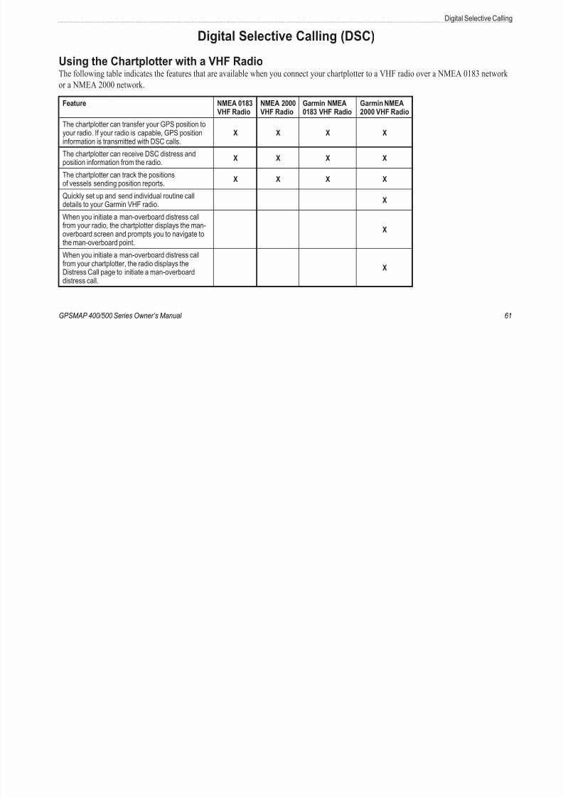
8/12/2019 garmin 421s manual
http://slidepdf.com/reader/full/garmin-421s-manual 67/84
GPSMAP 400/500 Series Owner’s Manual
Using the Chartplotter with a VHF RadioThe following table indicates the features that are available when you connect your chartplotter to a VHF radio over a NMEA 0183 networ
or a NMEA 2000 network.
Feature NMEA 0183VHF Radio NMEA 2000VHF Radio Garmin NMEA0183 VHF Radio Garmin NMEA2000 VHF Radio
The chartplotter can transfer your GPS position toyour radio. If your radio is capable, GPS positioninformation is transmitted with DSC calls.
X X X X
The chartplotter can receive DSC distress andposition information from the radio.
X X X X
The chartplotter can track the positionsof vessels sending position reports.
X X X X
Quickly set up and send individual routine calldetails to your Garmin VHF radio. X
When you initiate a man-overboard distress callfrom your radio, the chartplotter displays the man-overboard screen and prompts you to navigate tothe man-overboard point.
X
When you initiate a man-overboard distress callfrom your chartplotter, the radio displays theDistress Call page to initiate a man-overboarddistress call.
X
Digital Selective Calling
To turn DSC on or off:
1. Select Confgure > Other Vessels.
2 Select DSC to toggle it on or off
Receiving Distress CallsIf your Garmin chartplotter and VHF radio are connected via NMEA
0183 NMEA 2000 h t l tt l t h VHF
8/12/2019 garmin 421s manual
http://slidepdf.com/reader/full/garmin-421s-manual 68/84
62 GPSMAP 400/500 Series Owner’s Manua
2. Select DSC to toggle it on or off.
Adding a DSC ContactYou can make calls to a DSC contact from the chartplotter. See
page 64 for information on making an individual routine call.
1. While viewing a chart, press MENU > Other Vessels > DSC >
DSC List > Add Contact.
2. Use the Rocker to enter the Maritime Mobile Service Identity
(MMSI) number of the vessel, and press SELECT.
3. Use the on-screen keyboard to enter the name of the vessel, and
select Done.
Viewing the DSC ListThe DSC list is a log of the most-recent DSC calls and other DSC
contacts you have entered. The DSC list can contain up to 100
entries. The DSC list shows the most-recent call from a boat. If a
second call is received from the same boat, it replaces the rst call in
the call list.
From a chart screen, press MENU > Other Vessels > DSC > DSC
List.
0183 or NMEA 2000, your chartplotter alerts you when your VHF
radio receives a DSC distress call. If position information was sent
with the distress call, that information is also available and recorded
with the call.
The symbol designates a distress call in the DSC List and marksthe position of a vessel on the Navigation chart at the time the DSC
distress call was sent.
When you receive a DSC distress call:
1. Select Review to view details about the call.
2. Complete one of the following:
Select Call with Radio to set up an individual routine call with
the radio to call the vessel in distress (page 64). This optionis only available if you are using a Garmin NMEA 2000-
compatible VHF radio.
Select Edit to edit the vessel name and add a comment. If
your radio is tracking the position of the vessel, select Trail to
show or hide the trail line for the vessel, and select Trail Line
to change the line color. Select Clear Report to delete the
call report. Select Create Waypoint to set a waypoint at the
position sent with the distress call.
•
•
Digital Selective Ca
Man-Overboard Distress Calls Initiated
from a VHF Radio
Position TrackingWhen you connect your Garmin chartplotter to a VHF radio using
NMEA 0183 t k l th t d iti t Thi
8/12/2019 garmin 421s manual
http://slidepdf.com/reader/full/garmin-421s-manual 69/84
GPSMAP 400/500 Series Owner’s Manual
When your Garmin chartplotter is connected to a Garmin NMEA
2000-compatible radio and you initiate a man-overboard DSC
distress call from your radio, your Garmin chartplotter displays the
man-overboard screen and prompts you to navigate to the man-
overboard point. If you have a Garmin autopilot system connectedto the network, your chartplotter prompts you to start a Williamson
turn to the man-overboard point.
If you cancel the man-overboard distress call on the radio, the man
overboard screen no longer appears.
Man-Overboard Distress Calls Initiated
from the Chartplotter When your Garmin chartplotter is connected to a Garmin NMEA
2000-compatible radio and you activate navigation to a man-
overboard location, the radio displays the Distress Call page to
initiate a man-overboard distress call. On the radio, press and hold
the DISTRESS key for at least three seconds to send the distress
call.
For information on placing distress calls from your Garmin radio,
see your Garmin VHF Radio Owner’s Manual. For information onactivating navigation to a man-overboard location, see page 25.
NMEA 0183, you can track vessels that send position reports. Thi
feature is also available with NMEA 2000, provided that the vess
sends the correct PGN data (PGN 129808; DSC Call Information
Every position report call received is logged in the DSC list
( page 41).
To view a list of position reports:
1. From the Home screen, select Information > Other Vessels
DSC List.
2. Select from the following options:
Select Call with Radio to set up an individual routine call
with the radio to call the vessel that sent the position report
This option is only available if you are using a Garmin NME
2000-compatible VHF radio.
Select Edit to edit the vessel name and the vessel symbol,
and to add a comment. If your radio is tracking the position
of the vessel, select Trail to show or hide the trail line for
the vessel, and select Trail Line to change the line color.
Select Clear Report to delete the call report. Select Create
Waypoint to set a waypoint at the position sent with the
distress call.
Select Clear Report to delete the call report.
•
•
•
Digital Selective Calling
Select Navigate To to Go To or Route To the location sent
with the position report (page 10).
C i V l T il th N i ti Ch t
• 3. Select Trail.
To change the symbol and color of the trail line for a vessel
1 From the Home screen select Information > Other Vessels >
8/12/2019 garmin 421s manual
http://slidepdf.com/reader/full/garmin-421s-manual 70/84
64 GPSMAP 400/500 Series Owner’s Manua
Conguring Vessel Trails on the Navigation ChartIf you have your chartplotter congured to show trails, the
Navigation chart displays a black dot for each reported position,
a black line indicating the path of the vessel, and a Blue Flag
symbol indicating the last reported position.
To set the duration of displayed trail points:
1. From a chart screen, press MENU > Other Vessels > DSC >
DSC Trails.
2. Select the number of hours to show tracked vessels on the
Navigation chart. For example, if you select 4 Hours, all
trail points (less than four hours old) for tracked vessels are
displayed.
To turn trail lines off for tracked vessels:
1. From a chart screen, press MENU > Other Vessels > DSC >
DSC Trails.
2. Select Off to turn trails off for every vessel.
To show or hide the trail line for a specic vessel that is
sending position reports:
1. From the Home screen, select Information > Other Vessels >
DSC List.
2. Select the vessel from the list > Edit.
1. From the Home screen, select Information > Other Vessels >
DSC List.
2. Select the vessel from the list > Edit.
3. Select an option:
Select Symbol to edit the symbol.
Select Trail Line to edit the line color.
Placing an Individual Routine CallWhen you connect your Garmin chartplotter to a Garmin VHF
NMEA 2000-compatible radio, you can use the chartplotter interfac
to set up an individual routine call. When setting up an individual
routine call from your chartplotter, you can select one of the
following channels on which you want to communicate. The radiotransmits this request with your call.
The selection of a DSC channel is limited to those channels that are
available in all frequency bands: 6, 8, 9, 10, 13, 15, 16, 17, 67, 68,
69, 71, 72, 73, or 77.
NOTE: The default channel is 72. However, select Channel to
select a different channel from the list. If you select a different
channel, the chartplotter uses that channel for subsequent calls untilyou call using a different channel.
•
•
Digital Selective Ca
To make an individual routine call:
1. While viewing a chart, press MENU > Other Vessels > DSC >
DSC List.

8/12/2019 garmin 421s manual
http://slidepdf.com/reader/full/garmin-421s-manual 71/84
GPSMAP 400/500 Series Owner’s Manual
2. Select the station to call from the list.
3. Select Review > Call with Radio.
4. Select Send to send the information about the call to the radio.
5. On your Garmin VHF radio, select Call.
Calling an AIS TargetWhen you connect your Garmin chartplotter to a Garmin VHF
NMEA 2000-compatible radio, you can use the chartplotter interface
to set up an individual routine call to an AIS target. For more
information on selecting a channel other than the default channel
(Channel 72), see ( page 64).
To make an individual routine call to an AIS target:1. While viewing a chart, use the Rocker to select an AIS
target .
2. Select AIS Vessel > Call with Radio.
3. Select Send to send the information about the call to the radio.
4. On your Garmin VHF radio, select Call.
Appendix
Appendix
Specications
Compass-Safe Distances:
Model Number Compass-SafeDistance
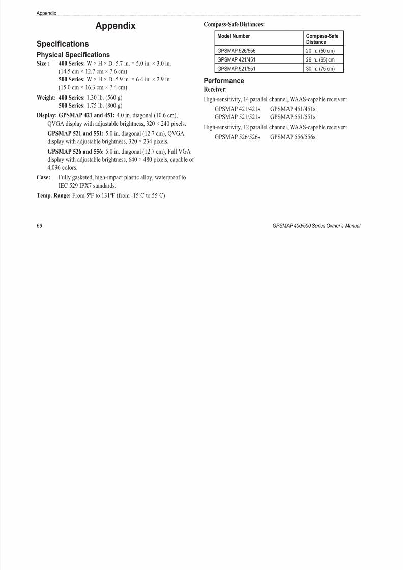
8/12/2019 garmin 421s manual
http://slidepdf.com/reader/full/garmin-421s-manual 72/84
66 GPSMAP 400/500 Series Owner’s Manua
Specications
Physical SpecicationsSize : 400 Series: W × H × D: 5.7 in. × 5.0 in. × 3.0 in.
(14.5 cm × 12.7 cm × 7.6 cm)
500 Series: W × H × D: 5.9 in. × 6.4 in. × 2.9 in.(15.0 cm × 16.3 cm × 7.4 cm)
Weight: 400 Series: 1.30 lb. (560 g)
500 Series: 1.75 lb. (800 g)
Display: GPSMAP 421 and 451: 4.0 in. diagonal (10.6 cm),
QVGA display with adjustable brightness, 320 × 240 pixels.
GPSMAP 521 and 551: 5.0 in. diagonal (12.7 cm), QVGA
display with adjustable brightness, 320 × 234 pixels. GPSMAP 526 and 556: 5.0 in. diagonal (12.7 cm), Full VGA
display with adjustable brightness, 640 × 480 pixels, capable of
4,096 colors.
Case: Fully gasketed, high-impact plastic alloy, waterproof to
IEC 529 IPX7 standards.
Temp. Range: From 5ºF to 131ºF (from -15ºC to 55ºC)
Distance
GPSMAP 526/556 20 in. (50 cm)
GPSMAP 421/451 26 in. (65) cm
GPSMAP 521/551 30 in. (75 cm)
PerformanceReceiver:
High-sensitivity, 14 parallel channel, WAAS-capable receiver:
GPSMAP 421/421s GPSMAP 451/451s
GPSMAP 521/521s GPSMAP 551/551s
High-sensitivity, 12 parallel channel, WAAS-capable receiver:
GPSMAP 526/526s GPSMAP 556/556s
Appe
Acquisition Times: (Average acquisition times for a stationary
receiver with a clear view of the sky)
GPSMAP 421/421s GPSMAP 451/451s
Power Power Source: 10–32 Vdc
Usage: 15 W max at 13.8 Vdc
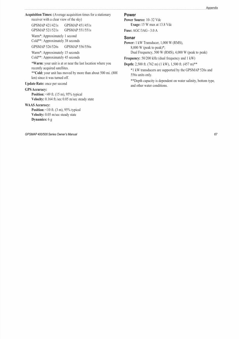
8/12/2019 garmin 421s manual
http://slidepdf.com/reader/full/garmin-421s-manual 73/84
GPSMAP 400/500 Series Owner’s Manual
GPSMAP 421/421s GPSMAP 451/451s
GPSMAP 521/521s GPSMAP 551/551s
Warm*: Approximately 1 second
Cold**: Approximately 38 seconds
GPSMAP 526/526s GPSMAP 556/556s
Warm*: Approximately 15 seconds
Cold**: Approximately 45 seconds
*Warm: your unit is at or near the last location where you
recently acquired satellites.
**Cold: your unit has moved by more than about 500 mi. (800
km) since it was turned off.
Update Rate: once per secondGPS Accuracy:
Position: <49 ft. (15 m), 95% typical
Velocity: 0.164 ft./sec 0.05 m/sec steady state
WAAS Accuracy:
Position: <10 ft. (3 m), 95% typical
Velocity: 0.05 m/sec steady state
Dynamics: 6 g
Us ge:
Fuse: AGC/3AG - 3.0 A
Sonar Power: 1 kW Transducer, 1,000 W (RMS),
8,000 W (peak to peak)*;
Dual Frequency, 500 W (RMS), 4,000 W (peak to peak)
Frequency: 50/200 kHz (dual frequency and 1 kW)
Depth: 2,500 ft. (762 m) (1 kW), 1,500 ft. (457 m)**
*1 kW transducers are supported by the GPSMAP 526s and
556s units only.
**Depth capacity is dependent on water salinity, bottom type
and other water conditions.
Appendix
Alarms and MessagesThe unit uses an on-screen message system to alert you to unit
operating characteristics. When a message appears, press MENU to
Boat Is Not Moving Fast Enough to Calibrate —the boat is not
moving fast enough for the speed wheel to provide a valid speed.
Can’t Read User Card error reading card; remove and reinsert
8/12/2019 garmin 421s manual
http://slidepdf.com/reader/full/garmin-421s-manual 74/84
68 GPSMAP 400/500 Series Owner’s Manua
operating characteristics. When a message appears, press MENU to
acknowledge the message.
Accuracy Alarm —the GPS accuracy has fallen outside of the user-
set value.
AIS: Dangerous Target —shows the MMSI (Maritime Mobile
Service Identity) of the dangerous target.
Alarm Clock —the alarm clock has sounded.
Anchor Drag Alarm —you have drifted out of the specied distance
range.
Antenna Input is Shorted —a part of the antenna wiring is crimped,
broken, or contacting the chassis.Arriving At [Waypoint Name] —you arrived at the destination
waypoint. You can Stop Navigation when this message appears.
Battery Alarm —battery voltage has fallen below the value entered
in the Battery Alarm setup.
Battery Voltage Is Too High —too much input voltage—the unit
shuts off in 10 seconds. Decrease the input voltage to the maximum
voltage allowed (or less) for your chartplotter.
Can t Read User Card —error reading card; remove and reinsert.
Contact your dealer or Garmin Product Support if the problem
persists.
Can’t Read Voltages That High, Limited To Top Of Range —the
voltage value in the Battery Alarm setup is higher than the unit can
read.
Can’t Read Voltages That Low, Limited To Bottom Of Range —
voltage value in the Battery Alarm setup is lower than the voltage
where the unit automatically turns off.
Can’t Unlock Maps —data on the data card is not unlocked for the
unit. Contact your dealer or Garmin Product Support.
Can’t Write User Card, Card May Be Full —error reading card;
remove and reinsert. Contact your dealer or Garmin Product Suppor
if the problem persists.
Can’t Write User Card, Card Is Read-Only —the SD card in your
unit contains data copy protection.
Card Needed —Your unit needs to have an SD card inserted into th
SD card slot in order to perform the function you requested.
Appe
DSC Position Report Received From —shows the MMSI or name
associated with an MMSI.
Database Error—internal problem with the unit Contact your
Fish Alarm —a beep sounds (if enabled) when a sh is detected.
This alarm does not show a message banner.
Invalid MMSI—enter a valid MMSI

8/12/2019 garmin 421s manual
http://slidepdf.com/reader/full/garmin-421s-manual 75/84
GPSMAP 400/500 Series Owner’s Manual
Database Error —internal problem with the unit. Contact your
dealer or Garmin Product Support to have the unit serviced.
Deep Water Alarm —the Deep Water Alarm depth has been
reached.
Directory Item With This MMSI Already Exists —the MMSI
number is already in the DSC directory. Use a different number.
Directory Memory is Full, Can’t Create Entry —the DSC
directory has reached the maximum of 100 contacts. Delete
unneeded contacts to add new ones.
Distress Call —a DSC distress call has been received. Take
appropriate action.
Entering (Leaving) target water temperature —the target water
temperature is 2°F (1.1°C) above or below the temperature specied
by the Water Temperature Alarm. These messages appear when you
enter or leave that zone.
Entering Safe Region —the boat is approaching a safe region as
dened by your conguration settings.
Entering Unsafe Region —the boat is approaching an unsafe regionas dened by your conguration settings.
Invalid MMSI —enter a valid MMSI.
Lost Satellite Reception —the unit has lost satellite signals. Chec
antenna connections or try moving to a location with a clear view
the sky.
NMEA Depth Is Below Transducer —you must enter an
appropriate Keel Offset for the transducer ( page 53).
No Waypoints/Routes/Tracks/User Waypoints Found— attemp
to transfer user data from an SD card that does not contain the
specied type of data. Make sure there is data to transfer on the S
card.
Off Course Alarm —you are off course the distance set in the “O
Course” alarm.
Route Already Exists —you entered a route name that already ex
in memory. Modify the route name or delete the previous route
name.
Route is Full —you attempted to add more than 250 points to a
route. Reduce the number of points or create a second route.
Route Truncated —an uploaded route from another device has mthan 250 waypoints and was truncated to t.
Appendix
Route Waypoint Memory Full —no additional route waypoints can
be saved.
Shallow Water Alarm—the Shallow Water Alarm depth has been
Track Truncated —a complete uploaded track does not t into
memory. The oldest track log points were deleted to make space for
the most recent data.
8/12/2019 garmin 421s manual
http://slidepdf.com/reader/full/garmin-421s-manual 76/84
70 GPSMAP 400/500 Series Owner’s Manua
Shallow Water Alarm the Shallow Water Alarm depth has been
reached.
Sonar Service Incompatible —the external sonar device you are
connected to needs a software update.
Sonar Timeout —there is an internal problem with the unit. Contact
your dealer or Garmin Product Support to have the unit serviced.
Sonar Service Lost —the external sonar device you were connected
to has either been disconnected or the unit has lost communication
with the sonar device for some other reason.
Track Already Exists [Track Name] —you entered a saved track
name that already exists in memory. Modify the track name or delete
the existing track.
Track Log Full —the track log is full and track recording has been
turned off. To record more track points, you need to clear the track
log and turn track recording on. This only appears when the track
recording setting is set to “Stop When Full.”
Track Memory is Full, Can’t Create Track —the track log
memory is full. No additional track log data can be stored without
deleting old data to create memory space.
Transducer Disconnected, Sonar Turned Off —there is not
a transducer attached, there is a bad cable or transducer, or the
transducer cable was disconnected. If the transducer cable is
removed while the unit is on, reconnect and cycle power.
Transfer Complete —the unit has nished uploading or
downloading information to the connected device.
User Card Not Found, Please Insert Card —attempted to transfer
user data without an SD card containing user data being present in
the SD card slot.
Warning: Auto-guidance route starting and ending position
moved due to safe depth settings —the auto-guidance route wascalculated but the starting and ending positions were moved because
of safe depth settings.
Water Speed Sensor Is Not Working —the speed sensor is not
detected. Check the connections.
Water Temperature Alarm —sonar has reported a temperature
above, below, inside, or outside the specied values.
Appe
Waypoint Already Exists —you entered a waypoint name that
already exists in memory. Modify the waypoint name or delete the
existing waypoint.
3. Copy the appropriate .BMP le on the card and paste it to any
location on the computer.
Caring for the Unit

8/12/2019 garmin 421s manual
http://slidepdf.com/reader/full/garmin-421s-manual 77/84
GPSMAP 400/500 Series Owner’s Manual
Waypoint Memory Full —you have saved the maximum number
of waypoints. Delete unwanted waypoints to make space for new
entries.
Capturing ScreenshotsYou can capture a screenshot of any screen displayed on your unit as
a bitmap (.BMP) le and then transfer it to your computer.
To capture screenshots:
1. Insert an SD card into the SD card slot on the front of the unit.
2. Select Confgure > System > Beeper/Display.
3. Select Screenshot Capture to turn screenshot captures On.4. When you are on a screen you want to capture, press and hold
the HOME button for at least six seconds.
5. Select OK when the Screenshot Taken window is displayed.
To copy the screenshots to your computer:
1. Remove the SD card from the chartplotter and insert it into an SD
card reader that is attached to a computer.
2. From Windows Explorer, open the Garmin\scrn folder on the SD
card.
Caring for the UnitThe case is constructed of high-quality materials and does not
require user maintenance, except cleaning.
Cleaning the CaseClean the unit’s outer casing (except for the screen) using a cloth
dampened with a mild detergent solution and then wipe dry. Avoi
chemical cleaners and solvents that may damage plastic compone
Cleaning the ScreenThe lens on the screen is coated with a special anti-reective coat
that is sensitive to skin oils, waxes, and abrasive cleaners. Cleane
containing ammonia, alcohol, abrasives, or anti-grease detergentswill harm the anti-reective coating. It is important to clean the le
using an eyeglass lens cleaner (that is specied as safe for anti-
reective coatings) and a clean, lint-free cloth.
Appendix
Honda Engine ECO SymbolThe symbol appears when boats with NMEA 2000-compatible
Honda engines are running in a fuel-efcient mode and engine RPM
Software License AgreementBY USING THE UNIT, YOU AGREE TO BE BOUND BY THE TERMS AND
CONDITIONS OF THE FOLLOWING SOFTWARE LICENSE AGREEMENT.
PLEASE READ THIS AGREEMENT CAREFULLY

8/12/2019 garmin 421s manual
http://slidepdf.com/reader/full/garmin-421s-manual 78/84
72 GPSMAP 400/500 Series Owner’s Manua
is displayed.
Consult your Honda engine manual to determine if the engine is
NMEA 2000 compatible.
NMEA 2000The following GPSMAP 400 and GPSMAP 500 series chartplotters
are NMEA 2000 certied and can receive data from a NMEA 2000
network installed on the boat.
GPSMAP 421/421s GPSMAP 521/521s
GPSMAP 451/451s GPSMAP 526/526s
GPSMAP 551/551s GPSMAP 556/556s
To connect one of these chartplotter to an existing NMEA 2000
network and to see a list of supported NMEA 2000 PGN numbers,
see the GPSMAP 400/500 Series Installation Instructions.
PLEASE READ THIS AGREEMENT CAREFULLY.
Garmin grants you a limited license to use the software embedded in this device
(the “Software”) in binary executable form in the normal operation of the product.
Title, ownership rights, and intellectual property rights in and to the Software
remain in Garmin.
You acknowledge that the Software is the property of Garmin and is protected
under the United States of America copyright laws and international copyright
treaties. You further acknowledge that the structure, organization, and code of
the Software are valuable trade secrets of Garmin and that the Software in source
code form remains a valuable trade secret of Garmin. You agree not to decompile,
disassemble, modify, reverse assemble, reverse engineer, or reduce to human
readable form the Software or any part thereof or create any derivative works based
on the Software. You agree not to export or re-export the Software to any country i
violation of the export control laws of the United States of America.
8/12/2019 garmin 421s manual
http://slidepdf.com/reader/full/garmin-421s-manual 79/84
Index
Eedit a route 27
edit existing waypoint 25
Edit Waypoint 25
grid coordinates
creating waypoints using 25
ground wind 36
guide to 23
Mmagnetic heading 37
Man Overboard 25, 63
Manual Zoom 60
north
grid 48
magnetic 48
true 48

8/12/2019 garmin 421s manual
http://slidepdf.com/reader/full/garmin-421s-manual 80/84
74 GPSMAP 400/500 Series Owner’s Manua
yp
EGNOS 47
Enter Coordinates 25
Event Log 47
Ffactory settings
restoring 5
sh eye 3D 17
settings 17
Fishing 9
shing chart 17
Fish Symbols 17, 59
frequency 60
Fuel Capacity 54
fuel gauge 35full screen, sonar 56
fuse 67
Ggain 60
Garmin Data Transfer 50
go to 23
GPS 4, 47, 67
GPS heading 37
Grid (North) 48
HHazard Colors 16
heading 48
GPS 37
magnetic 37
Heading Line 13
heading source 37
Head Up 12
HOME key 4
Iicon 13
ID number 5
Kkeel offset 53
keypad 4
LLabel Devices 51
Lane Width 15, 17
Language 48
Light Sectors 13
map datum 48
MapSource data 39
mariner’s eye 3D 15
colors 16
mark current location 25measuring distance 26
MENU key 4
messages 68
move a waypoint 25
My Boat 53
N Navaid Size 13
Navaid Type 13
Navigate To 10, 24, 26, 27, 64 Navigation Alarms 52
navigation charts 7
navigation preferences 48
New Waypoint 15
NMEA 0183 Setup 50
NMEA 2000 Setup 51
NMEA High Speed 50
NMEA Standard 50
Noise Reject 60
north up 12
No Zoom 60
numbers
customizing 31
overlay numbers 9viewing 31
Oobject information
accessing 11
Other Vessels 54
PPause Sonar 60
Perspective 3D 14
Photo Points 13
photos 11
physical specications 66
Points of Interest (POI) 13, 21, 30
Position Format 48
position reports 63
position tracking 63
Posn. Precision 51
Power/Backlight key 4
power source 67
product registration iv
In
Qquick links i
Rdi 61
screenshots 71
scroll speed 59
SD cards
inserting 5
i
sonar
advanced settings 60
cone 17
full screen 56
ll d
tide stations 37
viewing information 11
Time (options) 48
tracks 17, 28
il

8/12/2019 garmin 421s manual
http://slidepdf.com/reader/full/garmin-421s-manual 81/84
GPSMAP 400/500 Series Owner’s Manual
radio 61
Range (sonar) 60
Range keys 4
Range Rings 15, 16
registering your product ivrestoring factory settings 5
Rocker key 4
Roses 12
routes
creating 26
deleting 28
editing 27
labels 48
viewing 39
route to 23
Ssafe-zone settings 55
Safe Depth 16, 49
Safe Height 49
Safety Shading 13
sailing data bar 9
satellite imagery
enabling 18
Saved Tracks 15
Save To Card 40, 47
removing 5
SELECT key 4
Serial Port setup 50
Service Points 11
settingsalarms 52
chart 11
communications 50
sh eye 3D 17
initializing 2
language 48
navigation preferences 48
system 47
units of measure 47
Shoreline Distance 49simulator 47
mode 5
Skyview 47
software license agreement 72
software version 47
scroll speed 59
setting up 59 – 60
setup 59
specications 67
split frequency 57split zoom 57
temperature log 58
specications 66
Speed Filter 47
Speed Sources 48
Split Frequency 57
Split Zoom 57
spot depths 13
Surface Noise 59
symbols 13System Alarms 52
System Information 47
viewing 5
system settings 47
System Units 47
TTemp Log 58
Temp Offset 54
Tides/Currents 11Animated 11
trails
AIS 44
DSC 64
transducer
dual frequency 60transferring data 39, 40
True (north) 48
true wind 36
turn the unit off 2
Turn Transition 48
Uunit ID number 5
units of measure 47
user data
backing up 40
clearing 39
transferring 40
viewing 39
VVehicle Icon 13
version (software) 47
VHF radio 61
8/12/2019 garmin 421s manual
http://slidepdf.com/reader/full/garmin-421s-manual 82/84
8/12/2019 garmin 421s manual
http://slidepdf.com/reader/full/garmin-421s-manual 83/84

8/12/2019 garmin 421s manual
http://slidepdf.com/reader/full/garmin-421s-manual 84/84
For the latest free software updates (excluding map data) throughout the life of your
Garmin products, visit the Garmin Web site at www.garmin.com.
© 2010 Garmin Ltd. or its subsidiaries
Garmin International, Inc.
1200 East 151st Street, Olathe, Kansas 66062, USA
Garmin (Europe) Ltd.
Liberty House, Hounsdown Business Park, Southampton, Hampshire, SO40 9LR UK
Garmin Corporation
No. 68, Jangshu 2nd Road, Sijhih, Taipei County, Taiwan
www.garmin.com
May 2010 Part Number 190-01230-10 Rev. A Printed in Taiw