ga 35 ga 36 ga 37 antenna installation instructions...ga 35, ga 36, and ga 37 antenna installation...
TRANSCRIPT
190-00848-00 March 2008 Revision B
GA 35 GA 36 GA 37 Antenna Installation Instructions

GA 35, GA 36, and GA 37 Antenna Installation Instructions Page B Revision B 190-00848-00
This Page Intentionally Left Blank
Page A GA 35, GA 36, and GA 37 Antenna Installation Instructions Revision B 190-00848-00
© Copyright 2007-2008
Garmin Ltd. Or its subsidiaries
All Rights Reserved
Except as expressly provided herein, no part of this manual may be reproduced, copied, transmitted, disseminated, downloaded or stored in any storage medium, for any purpose without the express prior written consent of Garmin. Garmin hereby grants permission to download a single copy of this manual and of any revision to this manual onto a hard drive or other electronic storage medium to be viewed and to print one copy of this manual or of any revision hereto, provided that such electronic or printed copy of this manual or revision must contain the complete text of this copyright notice and provided further that any unauthorized commercial distribution of this manual or any revision hereto is strictly prohibited.
Garmin International, Inc. 1200 E. 151st Street
Olathe, KS 66062 USA Telephone: 913.397.8200
Aviation Dealer Technical Support Line (Toll Free): 888.606.5482 www.garmin.com
Garmin (Europe) Ltd. Liberty House
Bull Copse Road Hounsdown Business Park
Southampton, SO40 9RB, UK Telephone: +44 (0) 870 850 1243
Garmin AT, Inc. 2345 Turner Rd., SE
Salem, OR 97302 USA Telephone: 503.581.8101
Revision Revision Date Description
A 7/30/2007 Initial Release B 3/18/08 Remove TSO-C129a

GA 35, GA 36, and GA 37 Antenna Installation Instructions Page B Revision B 190-00848-00
This Page Intentionally Left Blank
GA 35, GA 36, and GA 37 Antenna Installation Instructions Page i 190-00848-00 Revision B
INFORMATION SUBJECT TO EXPORT CONTROL LAWS
This document may contain information which is subject to the Export Administration Regulations (“EAR”) issued by the United States Department of Commerce (15 CFR, Chapter VII, Subchapter C) and which may not be exported, released, or disclosed to foreign nationals inside or outside of the United States without first obtaining an export license. A violation of the EAR may be subject to a penalty of up to 10 years imprisonment and a fine up to $1,000,000 under Section 2410 of the export Administration Act of 1979. Include this notice with any reproduced portion of this document.
WARNING This product, its packaging, and its components contain chemicals known to the State of California to cause cancer, birth defects, or reproductive harm. This Notice is being provided in accordance with California’s Proposition 65. If you have any questions or would like additional information, please refer to our website at www.garmin.com.
NOTE Throughout this document references made to the GA 3X shall equally apply to the antennas list in Table 1-1Table 1-1 except where specifically noted.
Page ii GA 35, GA 36, and GA 37 Antenna Installation Instructions Revision B 190-00848-00
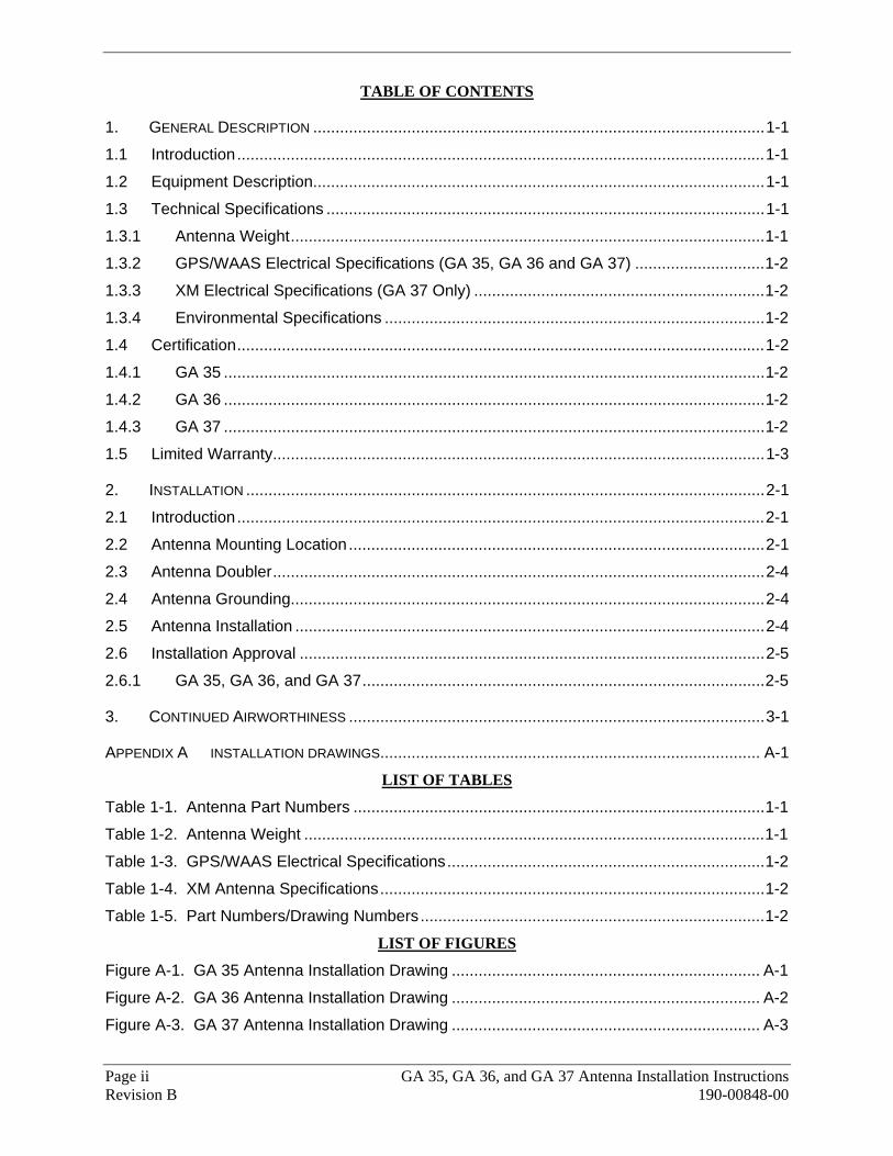
TABLE OF CONTENTS
1. GENERAL DESCRIPTION .....................................................................................................1-1 1.1 Introduction......................................................................................................................1-1 1.2 Equipment Description.....................................................................................................1-1 1.3 Technical Specifications ..................................................................................................1-1 1.3.1 Antenna Weight..........................................................................................................1-1 1.3.2 GPS/WAAS Electrical Specifications (GA 35, GA 36 and GA 37) .............................1-2 1.3.3 XM Electrical Specifications (GA 37 Only) .................................................................1-2 1.3.4 Environmental Specifications .....................................................................................1-2 1.4 Certification......................................................................................................................1-2 1.4.1 GA 35 .........................................................................................................................1-2 1.4.2 GA 36 .........................................................................................................................1-2 1.4.3 GA 37 .........................................................................................................................1-2 1.5 Limited Warranty..............................................................................................................1-3
2. INSTALLATION ....................................................................................................................2-1 2.1 Introduction......................................................................................................................2-1 2.2 Antenna Mounting Location.............................................................................................2-1 2.3 Antenna Doubler..............................................................................................................2-4 2.4 Antenna Grounding..........................................................................................................2-4 2.5 Antenna Installation .........................................................................................................2-4 2.6 Installation Approval ........................................................................................................2-5 2.6.1 GA 35, GA 36, and GA 37..........................................................................................2-5
3. CONTINUED AIRWORTHINESS .............................................................................................3-1
APPENDIX A INSTALLATION DRAWINGS..................................................................................... A-1 LIST OF TABLES
Table 1-1. Antenna Part Numbers ............................................................................................1-1 Table 1-2. Antenna Weight .......................................................................................................1-1 Table 1-3. GPS/WAAS Electrical Specifications.......................................................................1-2 Table 1-4. XM Antenna Specifications......................................................................................1-2 Table 1-5. Part Numbers/Drawing Numbers.............................................................................1-2
LIST OF FIGURES
Figure A-1. GA 35 Antenna Installation Drawing ..................................................................... A-1 Figure A-2. GA 36 Antenna Installation Drawing ..................................................................... A-2 Figure A-3. GA 37 Antenna Installation Drawing ..................................................................... A-3
GA 35, GA 36, and GA 37 Antenna Installation Instructions Page 1-1 190-00848-00 Revision B
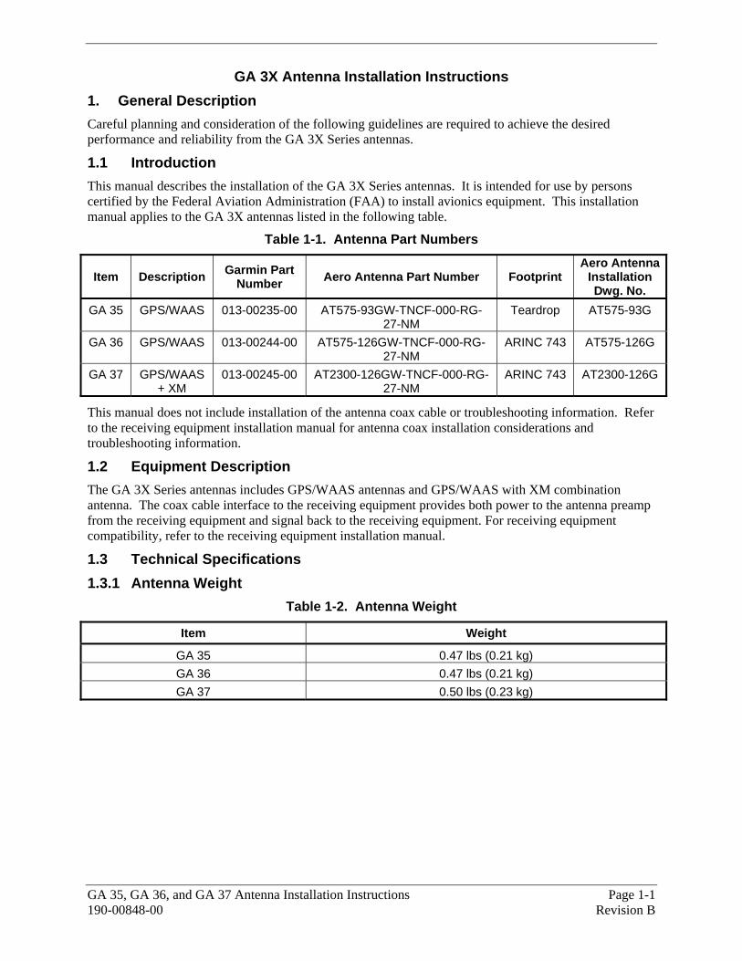
GA 3X Antenna Installation Instructions 1. General Description Careful planning and consideration of the following guidelines are required to achieve the desired performance and reliability from the GA 3X Series antennas.
1.1 Introduction This manual describes the installation of the GA 3X Series antennas. It is intended for use by persons certified by the Federal Aviation Administration (FAA) to install avionics equipment. This installation manual applies to the GA 3X antennas listed in the following table.
Table 1-1. Antenna Part Numbers
Item Description Garmin Part Number Aero Antenna Part Number Footprint
Aero Antenna Installation Dwg. No.
GA 35 GPS/WAAS 013-00235-00 AT575-93GW-TNCF-000-RG-27-NM
Teardrop AT575-93G
GA 36 GPS/WAAS 013-00244-00 AT575-126GW-TNCF-000-RG-27-NM
ARINC 743 AT575-126G
GA 37 GPS/WAAS + XM
013-00245-00 AT2300-126GW-TNCF-000-RG-27-NM
ARINC 743 AT2300-126G
This manual does not include installation of the antenna coax cable or troubleshooting information. Refer to the receiving equipment installation manual for antenna coax installation considerations and troubleshooting information.
1.2 Equipment Description The GA 3X Series antennas includes GPS/WAAS antennas and GPS/WAAS with XM combination antenna. The coax cable interface to the receiving equipment provides both power to the antenna preamp from the receiving equipment and signal back to the receiving equipment. For receiving equipment compatibility, refer to the receiving equipment installation manual.
1.3 Technical Specifications 1.3.1 Antenna Weight
Table 1-2. Antenna Weight
Item Weight
GA 35 0.47 lbs (0.21 kg) GA 36 0.47 lbs (0.21 kg) GA 37 0.50 lbs (0.23 kg)
Page 1-2 GA 35, GA 36, and GA 37 Antenna Installation Instructions Revision B 190-00848-00
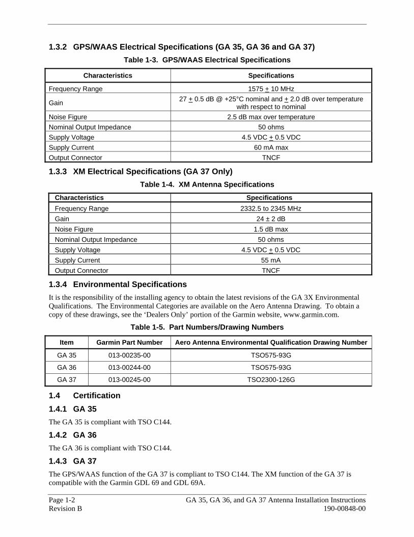
1.3.2 GPS/WAAS Electrical Specifications (GA 35, GA 36 and GA 37) Table 1-3. GPS/WAAS Electrical Specifications
Characteristics Specifications
Frequency Range 1575 + 10 MHz
Gain 27 + 0.5 dB @ +25°C nominal and + 2.0 dB over temperature with respect to nominal
Noise Figure 2.5 dB max over temperature Nominal Output Impedance 50 ohms Supply Voltage 4.5 VDC + 0.5 VDC Supply Current 60 mA max Output Connector TNCF
1.3.3 XM Electrical Specifications (GA 37 Only) Table 1-4. XM Antenna Specifications
Characteristics Specifications Frequency Range 2332.5 to 2345 MHz Gain 24 ± 2 dB Noise Figure 1.5 dB max Nominal Output Impedance 50 ohms Supply Voltage 4.5 VDC + 0.5 VDC Supply Current 55 mA Output Connector TNCF
1.3.4 Environmental Specifications It is the responsibility of the installing agency to obtain the latest revisions of the GA 3X Environmental Qualifications. The Environmental Categories are available on the Aero Antenna Drawing. To obtain a copy of these drawings, see the ‘Dealers Only’ portion of the Garmin website, www.garmin.com.
Table 1-5. Part Numbers/Drawing Numbers
Item Garmin Part Number Aero Antenna Environmental Qualification Drawing Number
GA 35 013-00235-00 TSO575-93G
GA 36 013-00244-00 TSO575-93G
GA 37 013-00245-00 TSO2300-126G
1.4 Certification 1.4.1 GA 35 The GA 35 is compliant with TSO C144.
1.4.2 GA 36 The GA 36 is compliant with TSO C144.
1.4.3 GA 37 The GPS/WAAS function of the GA 37 is compliant to TSO C144. The XM function of the GA 37 is compatible with the Garmin GDL 69 and GDL 69A.

GA 35, GA 36, and GA 37 Antenna Installation Instructions Page 1-3 190-00848-00 Revision B
1.5 Limited Warranty This Garmin product is warranted to be free from defects in materials or workmanship for one year from the date of purchase. Within this period, Garmin will at its sole option, repair or replace any components that fail in normal use. Such repairs or replacement will be made at no charge to the customer for parts or labor, provided that the customer shall be responsible for any transportation cost. This warranty does not cover failures due to abuse, misuse, accident or unauthorized alteration or repairs.
THE WARRANTIES AND REMEDIES CONTAINED HEREIN ARE EXCLUSIVE AND IN LIEU OF ALL OTHER WARRANTIES EXPRESS OR IMPLIED OR STATUTORY, INCLUDING ANY LIABILITY ARISING UNDER ANY WARRANTY OF MERCHANTABILITY OR FITNESS FOR A PARTICULAR PURPOSE, STATUTORY OR OTHERWISE. THIS WARRANTY GIVES YOU SPECIFIC LEGAL RIGHTS, WHICH MAY VARY FROM STATE TO STATE.
IN NO EVENT SHALL GARMIN BE LIABLE FOR ANY INCIDENTAL, SPECIAL, INDIRECT OR CONSEQUENTIAL DAMAGES, WHETHER RESULTING FROM THE USE, MISUSE, OR INABILITY TO USE THIS PRODUCT OR FROM DEFECTS IN THE PRODUCT. Some states do not allow the exclusion of incidental or consequential damages, so the above limitations may not apply to you.
Garmin retains the exclusive right to repair or replace the unit or software or offer a full refund of the purchase price at its sole discretion. SUCH REMEDY SHALL BE YOUR SOLE AND EXCLUSIVE REMEDY FOR ANY BREACH OF WARRANTY. To obtain warranty service, contact your local Garmin Authorized Service Center. For assistance in locating a Service Center near you, call Garmin Customer Service at one of the numbers shown below.
Products sold through online auctions are not eligible for rebates or other special offers from Garmin. Online auction confirmations are not accepted for warranty verification. To obtain warranty service, an original or copy of the sales receipt from the original retailer is required. Garmin will not replace missing components from any package purchased through an online auction.
Garmin International, Inc. Garmin (Europe) Ltd. 1200 East 151st Street Liberty House Olathe, Kansas 66062, U.S.A. Bull Copse Road Phone: 913/397.8200 Hounsdown Business Park FAX: 913/397.0836 Southampton, SO40 9RB, UK
Telephone: +44 (0) 870-850 1243

Page 1-4 GA 35, GA 36, and GA 37 Antenna Installation Instructions Revision B 190-00848-00
This Page Intentionally Left Blank
GA 35, GA 36, and GA 37 Antenna Installation Instructions Page 2-1 190-00848-00 Revision B
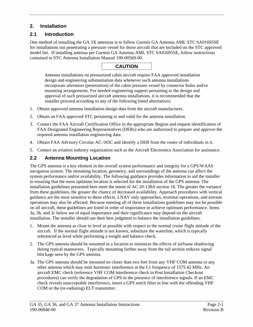
2. Installation 2.1 Introduction One method of installing the GA 3X antennas is to follow Garmin GA Antenna AML STC SA01695SE for installations not penetrating a pressure vessel for those aircraft that are included on the STC approved model list. If installing antenna per Garmin GA Antenna AML STC SA01695SE, follow instructions contained in STC Antenna Installation Manual 190-00569-00.
CAUTION Antenna installations on pressurized cabin aircraft require FAA approved installation design and engineering substantiation data whenever such antenna installations incorporate alteration (penetration) of the cabin pressure vessel by connector holes and/or mounting arrangements. For needed engineering support pertaining to the design and approval of such pressurized aircraft antenna installations, it is recommended that the installer proceed according to any of the following listed alternatives:
1. Obtain approved antenna installation design data from the aircraft manufacturer.
2. Obtain an FAA approved STC pertaining to and valid for the antenna installation.
3. Contact the FAA Aircraft Certification Office in the appropriate Region and request identification of FAA Designated Engineering Representatives (DERs) who are authorized to prepare and approve the required antenna installation engineering data.
4. Obtain FAA Advisory Circular AC-183C and identify a DER from the roster of individuals in it.
5. Contact an aviation industry organization such as the Aircraft Electronics Association for assistance.
2.2 Antenna Mounting Location The GPS antenna is a key element in the overall system performance and integrity for a GPS/WAAS navigation system. The mounting location, geometry, and surroundings of the antenna can affect the system performance and/or availability. The following guidance provides information to aid the installer in ensuring that the most optimum location is selected for the installation of the GPS antenna. The installation guidelines presented here meet the intent of AC 20-138A section 16. The greater the variance from these guidelines, the greater the chance of decreased availability. Approach procedures with vertical guidance are the most sensitive to these effects. LNAV only approaches, terminal operations, and enroute operations may also be affected. Because meeting all of these installations guidelines may not be possible on all aircraft, these guidelines are listed in order of importance to achieve optimum performance. Items 3a, 3b, and 3c below are of equal importance and their significance may depend on the aircraft installation. The installer should use their best judgment to balance the installation guidelines.
1. Mount the antenna as close to level as possible with respect to the normal cruise flight attitude of the aircraft. If the normal flight attitude is not known, substitute the waterline, which is typically referenced as level while performing a weight and balance check.
2. The GPS antenna should be mounted in a location to minimize the effects of airframe shadowing during typical maneuvers. Typically mounting farther away from the tail section reduces signal blockage seen by the GPS antenna.
3a. The GPS antenna should be mounted no closer than two feet from any VHF COM antenna or any other antenna which may emit harmonic interference at the L1 frequency of 1575.42 MHz. An aircraft EMC check (reference VHF COM interference check in Post Installation Checkout procedures) can verify the degradation of GPS in the presence of interference signals. If an EMC check reveals unacceptable interference, insert a GPS notch filter in line with the offending VHF COM or the (re-radiating) ELT transmitter.
Page 2-2 GA 35, GA 36, and GA 37 Antenna Installation Instructions Revision B 190-00848-00
Note: When mounting a combination antenna, the recommended distance of two feet or more is not applicable to the distance between the antenna elements in a combination antenna (ex. GPS and COM, GPS and XM) provided the combination antenna is TSO authorized and has been tested to meet Garmin’s minimum performance standards.
3b. The GPS antenna should be mounted no closer than two feet from any antennas emitting more than 25 watts of power. An aircraft EMC check can verify the degradation of GPS in the presence of interference signals.
3c. To minimize the effects of shadowing at 5° elevation angles, the GPS antenna should be mounted no closer than 6 inches (edge to edge) from other antennas, including passive antennas such as another GPS antenna or XM antenna.
4. To maintain a constant gain pattern and limit degradation by the windscreen, avoid mounting the antenna closer than 3 inches from the windscreen.
5. For multiple GPS installations, the antennas should not be mounted in a straight line from the front to the rear of the fuselage. Also varying the mounting location will help minimize any aircraft shading by the wings or tail section (in a particular azimuth, when one antenna is blocked the other antenna may have a clear view).
Figure 2-1Figure 2-1 shows the recommended placement of antennas.

GA 35, GA 36, and GA 37 Antenna Installation Instructions Page 2-3 190-00848-00 Revision B
Figure 2-1. GPS Antenna Installation Considerations
Page 2-4 GA 35, GA 36, and GA 37 Antenna Installation Instructions Revision B 190-00848-00
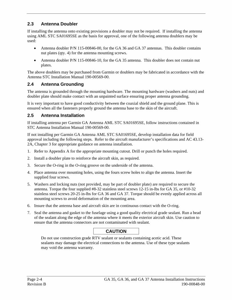
2.3 Antenna Doubler If installing the antenna onto existing provisions a doubler may not be required. If installing the antenna using AML STC SA01695SE as the basis for approval, one of the following antenna doublers may be used:
• Antenna doubler P/N 115-00846-00, for the GA 36 and GA 37 antennas. This doubler contains nut plates (qty. 4) for the antenna mounting screws.
• Antenna doubler P/N 115-00846-10, for the GA 35 antenna. This doubler does not contain nut plates.
The above doublers may be purchased from Garmin or doublers may be fabricated in accordance with the Antenna STC Installation Manual 190-00569-00.
2.4 Antenna Grounding The antenna is grounded through the mounting hardware. The mounting hardware (washers and nuts) and doubler plate should make contact with an unpainted surface ensuring proper antenna grounding.
It is very important to have good conductivity between the coaxial shield and the ground plane. This is ensured when all the fasteners properly ground the antenna base to the skin of the aircraft.
2.5 Antenna Installation If installing antenna per Garmin GA Antenna AML STC SA01695SE, follow instructions contained in STC Antenna Installation Manual 190-00569-00.
If not installing per Garmin GA Antenna AML STC SA01695SE, develop installation data for field approval including the following steps. Refer to the aircraft manufacturer’s specifications and AC 43.13-2A, Chapter 3 for appropriate guidance on antenna installation.
1. Refer to Appendix A for the appropriate mounting cutout. Drill or punch the holes required.
2. Install a doubler plate to reinforce the aircraft skin, as required.
3. Secure the O-ring in the O-ring groove on the underside of the antenna.
4. Place antenna over mounting holes, using the fours screw holes to align the antenna. Insert the supplied four screws.
5. Washers and locking nuts (not provided, may be part of doubler plate) are required to secure the antenna. Torque the four supplied #8-32 stainless steel screws 12-15 in-lbs for GA 35, or #10-32 stainless steel screws 20-25 in-lbs for GA 36 and GA 37. Torque should be evenly applied across all mounting screws to avoid deformation of the mounting area.
6. Insure that the antenna base and aircraft skin are in continuous contact with the O-ring.
7. Seal the antenna and gasket to the fuselage using a good quality electrical grade sealant. Run a bead of the sealant along the edge of the antenna where it meets the exterior aircraft skin. Use caution to ensure that the antenna connectors are not contaminated with sealant.
CAUTION Do not use construction grade RTV sealant or sealants containing acetic acid. These sealants may damage the electrical connections to the antenna. Use of these type sealants may void the antenna warranty.
GA 35, GA 36, and GA 37 Antenna Installation Instructions Page 2-5 190-00848-00 Revision B
2.6 Installation Approval 2.6.1 GA 35, GA 36, and GA 37 The conditions and tests required for TSO approval of the GA 3X antennas are minimum performance standards. It is the responsibility of those desiring to install the antenna either on or within a specific type or class of aircraft to determine the aircraft installation standards are within the TSO standards. One method of installing the GA 3X antennas is per GA Antenna AML STC SA01695SE. For other methods, the GA 3X antennas may be installed only if further evaluation by the applicant documents an acceptable installation and is approved by the administrator. For antenna TSO compliance, see Section 1.4.
Page 2-6 GA 35, GA 36, and GA 37 Antenna Installation Instructions Revision B 190-00848-00
This Page Intentionally Left Blank
GA 35, GA 36, and GA 37 Antenna Installation Instructions Page 3-1 190-00848-00 Revision B
3. Continued Airworthiness
Maintenance of the GA 3X antenna is “on-condition” only. Periodic maintenance of the GA 3X antenna is not required.

Page 3-2 GA 35, GA 36, and GA 37 Antenna Installation Instructions Revision B 190-00848-00
This Page Intentionally Left Blank
GA 35, GA 36, and GA 37 Antenna Installation Instructions Page A-1 190-00848-00 Revision B
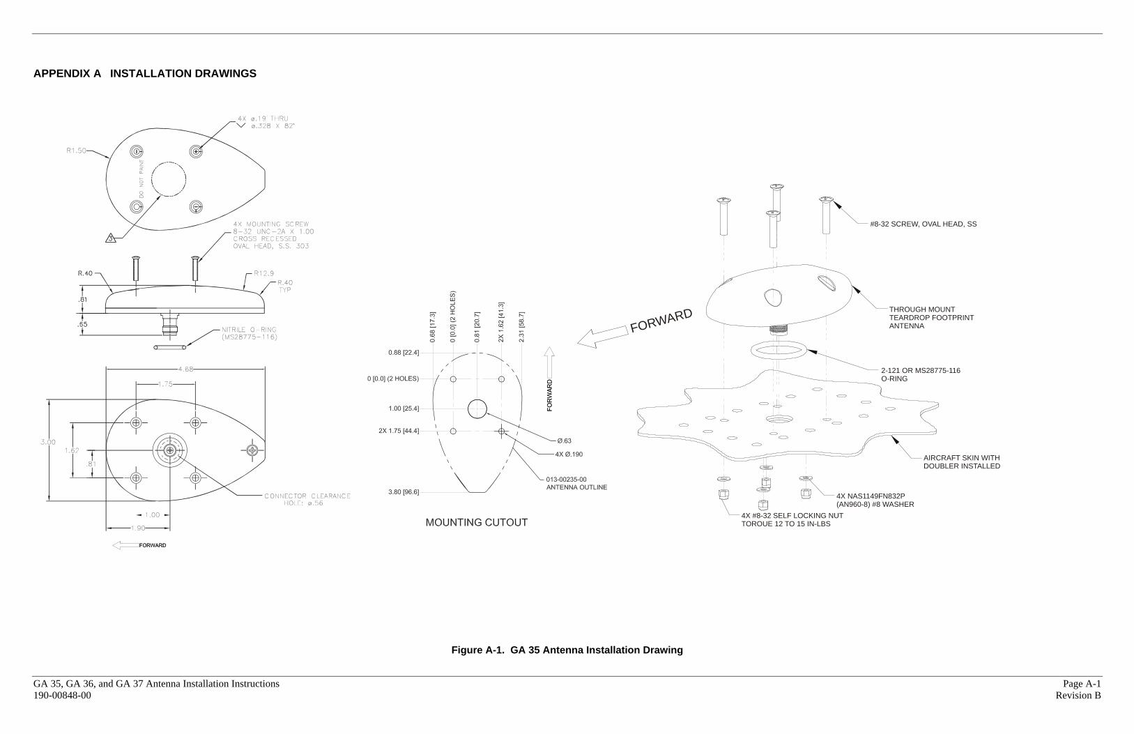
APPENDIX A INSTALLATION DRAWINGS
Figure A-1. GA 35 Antenna Installation Drawing
4X #8-32 SELF LOCKING NUTTORQUE 12 TO 15 IN-LBS
4X NAS1149FN832P(AN960-8) #8 WASHER
AIRCRAFT SKIN WITHDOUBLER INSTALLED
2-121 OR MS28775-116O-RING
THROUGH MOUNTTEARDROP FOOTPRINTANTENNAFORWARD
#8-32 SCREW, OVAL HEAD, SS

Page A-2 GA 35, GA 36, and GA 37 Antenna Installation Instructions Revision B 190-00848-00
4X MOUNTING SCREW10-32 UNF-2A X 1.00CROSS RECESSED
FLAT HEAD 100°, SS
FORWARD
AIRCRAFT SKIN WITHDOUBLER INSTALLED
013-00244-00ANTENNA
O-RING(MS28775-142)
4X NAS1149C0363R(AN960C-10)#10 WASHER, S.S.
4X SELF LOCKING NUT10-32 UNF-2A, S.S.TORQUE 20 TO 25 in-lbs
.63
.2204X
013-00244-00ANTENNA OUTLINE
FOR
WA
RD
MOUNTING CUTOUT
0.70
[17.
8]
0 [0
.0] (
2 H
OLE
S)
0.80
[20.
3]
2X 1
.60
[40.
6]
2.30
[58.
4]
0.70 [17.7]
0 [0.0] (2 HOLES)
1.04 [26.4]
2X 3.30 [83.8]
4.00 [101.6]
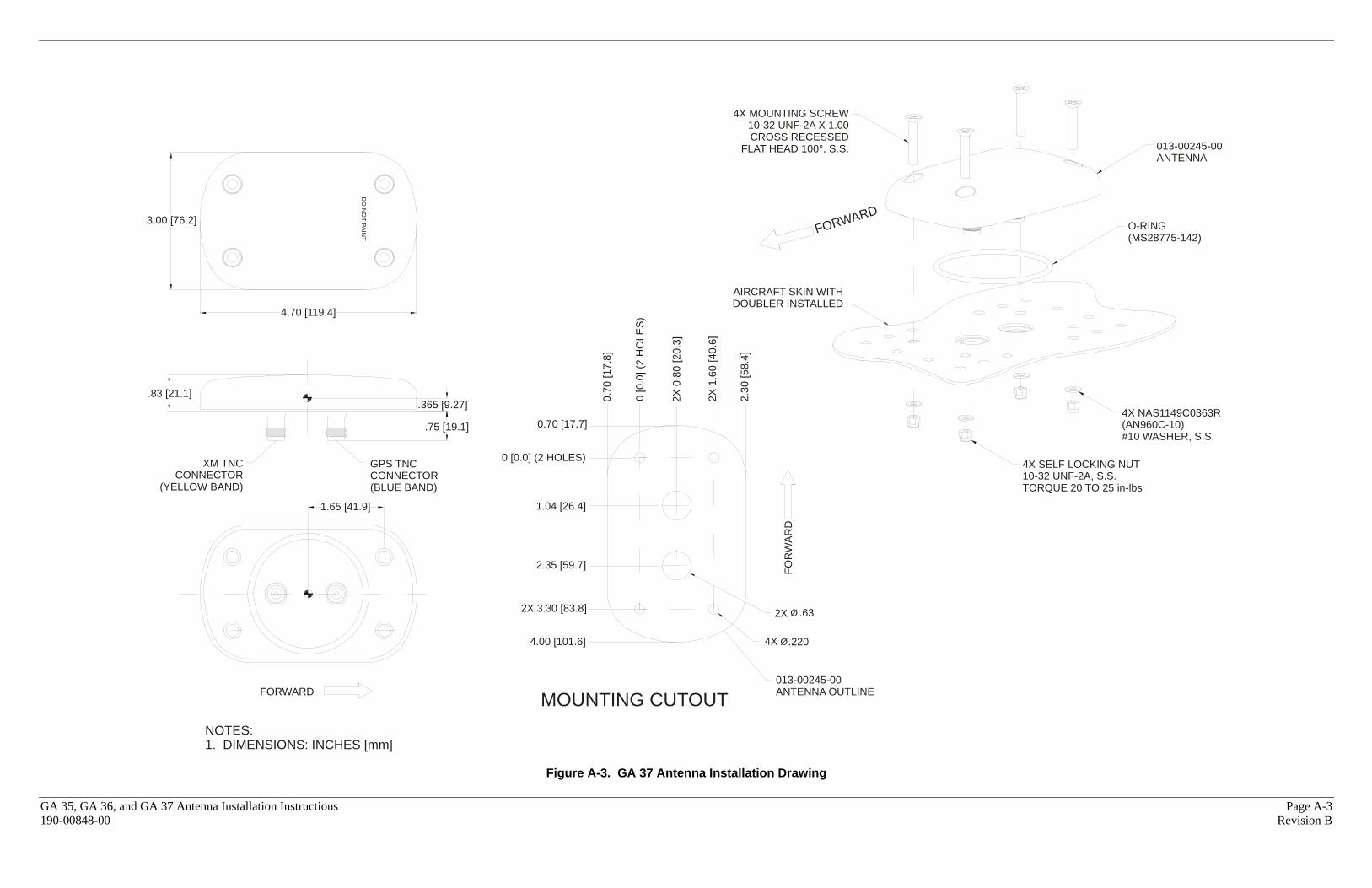
NOTES:1. DIMENSIONS: INCHES [mm]
FORWARD
1.65 [41.9]
GPS TNCCONNECTOR
.75 [19.1]
.365 [9.27]
4.70 [119.4]
DO
NO
T PAIN
T
3.00 [76.2]
.78 [19.8]
Figure A-2. GA 36 Antenna Installation Drawing
GA 35, GA 36, and GA 37 Antenna Installation Instructions Page A-3 190-00848-00 Revision B
4X MOUNTING SCREW10-32 UNF-2A X 1.00CROSS RECESSED
FLAT HEAD 100°, S.S.
MOUNTING CUTOUTNOTES:1. DIMENSIONS: INCHES [mm]
FORWARD
DO
NO
T PAINT FORWARD
AIRCRAFT SKIN WITHDOUBLER INSTALLED
013-00245-00ANTENNA
O-RING(MS28775-142)
4X NAS1149C0363R(AN960C-10)#10 WASHER, S.S.
4X SELF LOCKING NUT10-32 UNF-2A, S.S.TORQUE 20 TO 25 in-lbs
.63
.2204X
013-00245-00ANTENNA OUTLINE
FOR
WA
RD
0.70
[17.
8]
0 [0
.0] (
2 H
OLE
S)
2X
0.8
0 [2
0.3]
2X 1
.60
[40.
6]
2.30
[58.
4]
0.70 [17.7]
0 [0.0] (2 HOLES)
1.04 [26.4]
2X 3.30 [83.8]
4.00 [101.6]
1.65 [41.9]
GPS TNCCONNECTOR(BLUE BAND)
.75 [19.1]
.365 [9.27]
4.70 [119.4]
3.00 [76.2]
.83 [21.1]
XM TNCCONNECTOR
(YELLOW BAND)
2.35 [59.7]
2X
Figure A-3. GA 37 Antenna Installation Drawing
Page A-4 GA 35, GA 36, and GA 37 Antenna Installation Instructions Revision B 190-00848-00
This Page Intentionally Left Blank