g01 through g10 double-acting pneumatic actuators with … valve automation... · g01 through g10...
TRANSCRIPT
Service InstructionsPart Number: 124843E, Rev. C
Release: August 2015
G01 through G10 Double-Acting Pneumatic Actuators with M11 Hydraulic Override

I
Service InstructionsPart Number:124843E, Rev. C
Table of ContentsAugust 2015
Table of Contents
Table of Contents
Section 1: Introduction 1.1 General Service Information ...................................................................... 11.2 Definitions ................................................................................................. 21.3 General Safety Information ........................................................................ 21.4 Bettis™ Reference Materials ....................................................................... 31.5 Service Support Items ................................................................................ 31.6 Lubrication and Fluid Requirements ............................................................ 31.7 General Tool Information ........................................................................... 41.8 Actuator Storage ........................................................................................ 41.9 Actuator Installation .................................................................................. 41.10 Actuator Start-Up ....................................................................................... 41.11 Actuator Operation .................................................................................... 5
Section 2: Actuator Disassembly 2.1 General Disassembly .................................................................................. 62.2 Pneumatic Power Module Disassembly ....................................................... 62.3 Drive Module Disassembly ......................................................................... 82.4 M11 Hydraulic Override Cylinder Disassembly .......................................... 10
Section 3: Actuator Reassembly 3.1 General Reassembly ................................................................................. 123.2 Drive Module Reassembly ........................................................................ 123.3 Pneumatic Power Module Reassembly ...................................................... 163.4 G2 and G3 Early Model Pneumatic Power Module Reassembly ................ 183.5 M11 Hydraulic Override Cylinder Reassembly .......................................... 203.6 Actuator Testing ....................................................................................... 22
Section 4: Field Conversions4.1 Construction Reversal (Exchange Module Locations) ................................ 24
Section 5: Module Removal and Installation5.1 Pneumatic Power Module Removal ........................................................... 255.2 Pneumatic Power Module Installation ....................................................... 255.3 M11 Hydraulic Override Cylinder Removal ................................................ 265.4 M11 Hydraulic Override Cylinder Installation ............................................ 265.5 Powr Swivl Module Removal ..................................................................... 285.6 Powr Swivl Module Installation ................................................................. 28
II
Service InstructionsPart Number:124843E, Rev. C
Table of ContentsAugust 2015
Table of Contents
Table of Contents (continued)Section 6: Actuator Support Information
6.1 M11 Hydraulic Override Fluid Volume ....................................................... 306.2 Module Weights by Item Number and Actuator Housing Size ................... 306.3 G01 Tool Style and Wrench Size ................................................................ 316.4 G2 Tool and Wrench Size .......................................................................... 326.5 G3 Tool and Wrench Size .......................................................................... 326.6 G4 Tool and Wrench Size .......................................................................... 336.7 G5 Tool and Wrench Size .......................................................................... 336.8 G7 Tool and Wrench Size .......................................................................... 346.9 G8 Tool and Wrench Size .......................................................................... 346.10 G10 Tool and Wrench Size ........................................................................ 35
Section 7: Troubleshooting7.1 Fault Insertion ........................................................................................... 367.2 Operational Test ...................................................................................... 37
Section 8: Removal and Decommissioning8.1 Removal and Decommissioning ................................................................ 38
Section 9: Document Revision Revision Overview ............................................................................................. 39
Appendix A: List of Tables List of Tables ...................................................................................................... 40
Appendix B: List of DrawingsB.1 Part No. 115680, GXXXX-H Pneumatic Assembly Dwg, Sheet 1 of 2.......... 41B.2 Part No. 115680, GXXXX-H Pneumatic Assembly Dwg, Sheet 2 of 2.......... 42B.3 Part No. 126567, M11 Assembly Dwg, Sheet 1 of 5 ................................... 43B.4 Part No. 126567, M11 Assembly Dwg, Sheet 2 of 5 ................................... 44B.5 Part No. 126567, M11 Assembly Dwg, Sheet 3 of 5 ................................... 45B.6 Part No. 126567, M11 Assembly Dwg, Sheet 4 of 5 ................................... 46B.7 Part No. 126567, M11 Assembly Dwg, Sheet 5 of 5 ................................... 47B.8 Part No. 121090, M11D-S Assembly Dwg, Sheet 1 of 3 ............................. 48B.9 Part No. 121090, M11D-S Assembly Dwg, Sheet 2 of 3 .............................. 49B.10 Part No. 121090, M11D-S Assembly Dwg, Sheet 3 of 3 .............................. 50B.11 Part No. 121107, M11S Remote Mount Assembly Dwg, Sheet 1 of 2 ......... 51B.12 Part No. 121107, M11S Remote Mount Assembly Dwg, Sheet 2 of 2 ......... 52

Service InstructionsPart Number:124843E, Rev. C August 2015
1
Section 1: Introduction
Introduction
Section 1: Introduction
1.1 General Service Information 1.1.1 This service procedure is offered as a guide to enable general maintenance to be
performed on Bettis™ G01XXX-M11, G2XXX M11, G3XXX M11, G4XXX M11, G5XXX M11, G7XXX M11, G8XXX M11, and G10XXX M11 Double-Acting G-Series Actuators with one Pneumatic Power Module and one M11 or M11 S Hydraulic Override Module.
1.1.2 Normal recommended service interval for this actuator series is five years.
NOTE: Storage time is counted as part of the service interval.
1.1.3 This procedure is applicable with the understanding that all electrical power and pneumatic pressure has been removed from the actuator.
1.1.4 Remove all piping and mounted accessories that will interfere with the module(s) that are to be worked on.
1.1.5 This procedure should only be implemented by a technically competent technician who should take care to observe good workmanship practices.
1.1.6 Numbers in parentheses, ( ) indicate the bubble number (reference number) used on the Bettis assembly drawing and Actuator Parts List.
1.1.7 This procedure is written using the stop screw side of the housing (1-10) as a reference and this side will be considered the front side of the actuator. The housing cover (1-20) will be the top of the actuator.
1.1.8 Actuator module weights are listed in Section 6 Table 6.2.
1.1.9 When removing seals from seal grooves, use a commercial seal removing tool or a small screwdriver with sharp corners rounded off.
1.1.10 Use a non-hardening thread sealant on all pipe threads.
CAUTION: FOLLOW MANUFACTURER'S INSTRUCTIONS Apply the thread sealant per the manufacturer’s instructions.
1.1.11 Bettis recommends that disassembly of the actuator components should be done in a clean area on a workbench.

August 2015Service Instructions
Part Number:124843E, Rev. C
2
Section 1: Introduction
Introduction
1.2 Definitions
WARNING: If not observed, user incurs a high risk of severe damage to actuator and/or fatal injury to personnel.
CAUTION: If not observed, user may incur damage to actuator and/or injury to personnel.
NOTE: Advisory and information comments provided to assist maintenance personnel to carry out maintenance procedures.
1.3 General Safety Information Products supplied by Bettis, in its “as shipped” condition, are intrinsically safe if the instructions contained within this Service Instruction are strictly adhered to and executed by well trained, equipped, prepared and competent personnel.
WARNING: READ WARNING MESSAGES CAREFULLYFor the protection of personnel working on Bettis actuators, this procedure should be reviewed and implemented for safe disassembly and reassembly. Close attention should be noted to the WARNINGS, CAUTIONS and NOTES contained in this procedure.
WARNING: FOLLOW PLANT SAFETY PROCEDURESThis procedure should not supersede or replace any customer’s plant safety or work procedures. If a conflict arises between this procedure and the customer’s procedures the differences should be resolved in writing between an authorized customer's representative and an authorized Bettis representative.
Service InstructionsPart Number:124843E, Rev. C August 2015
3
Section 1: Introduction
Introduction
1.4 Bettis Reference Materials 1.4.1 Assembly Drawing for G01-M11 through G10-M11 Double-Acting with one Pneumatic
Power Module and one Hydraulic Override Module use part number 115680.
1.4.2 M11 Manual Hydraulic Override System operating instructions part number 126858 with M11 Assembly Drawing part number 126567.
1.4.3 M11-S Manual Hydraulic Override System operating instructions part number 121962 with M11-S Assembly Drawing part number 121090.
NOTE: If you require a specific assembly drawing (IE: GXX-M3 OR HYD) please contact Emerson Valve Automation Bettis by phone or email at [email protected]
1.5 Service Support Items 1.5.1 Bettis module service kits.
1.5.2 For rod extension retainer nut tool part number, refer to the following table.
NOTE: These tools are required only when extension rod assembly (1-50) or (9-50) is removed or when a new extension rod assembly is installed.
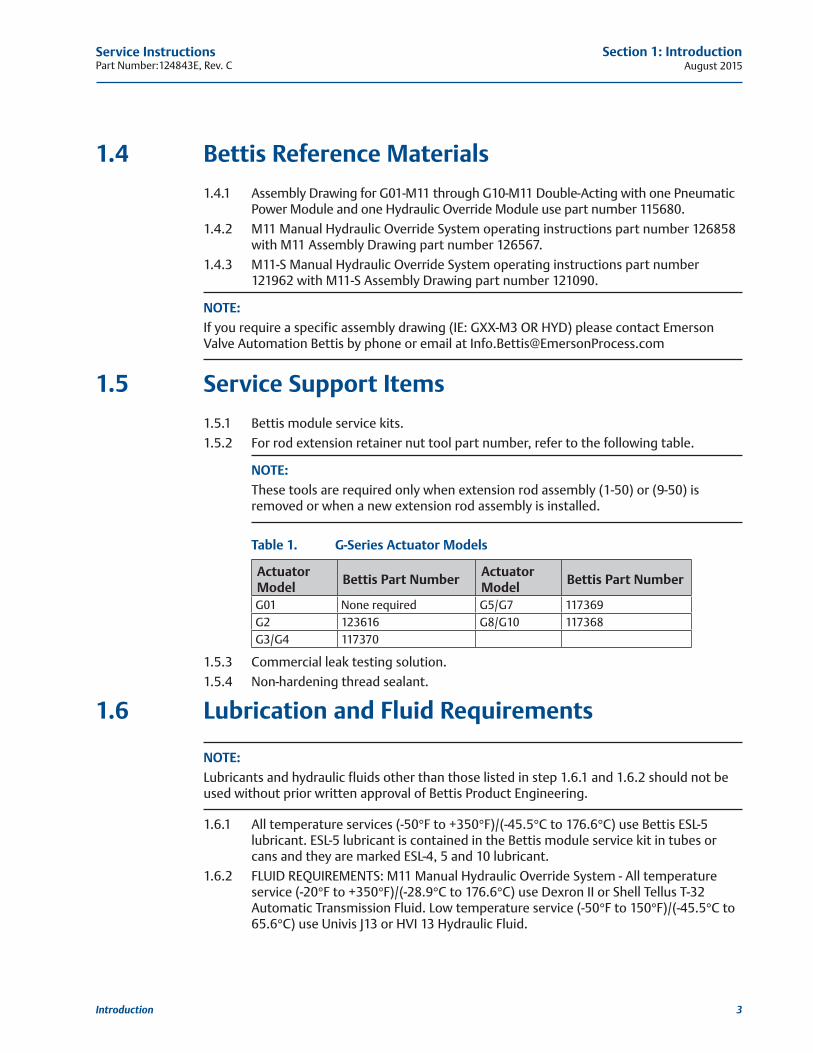
Table 1. G-Series Actuator Models
Actuator Model Bettis Part Number Actuator
Model Bettis Part Number
G01 None required G5/G7 117369G2 123616 G8/G10 117368G3/G4 117370
1.5.3 Commercial leak testing solution.
1.5.4 Non-hardening thread sealant.
1.6 Lubrication and Fluid Requirements
NOTE: Lubricants and hydraulic fluids other than those listed in step 1.6.1 and 1.6.2 should not be used without prior written approval of Bettis Product Engineering.
1.6.1 All temperature services (-50°F to +350°F)/(-45.5°C to 176.6°C) use Bettis ESL-5 lubricant. ESL-5 lubricant is contained in the Bettis module service kit in tubes or cans and they are marked ESL-4, 5 and 10 lubricant.
1.6.2 FLUID REQUIREMENTS: M11 Manual Hydraulic Override System - All temperature service (-20°F to +350°F)/(-28.9°C to 176.6°C) use Dexron II or Shell Tellus T-32 Automatic Transmission Fluid. Low temperature service (-50°F to 150°F)/(-45.5°C to 65.6°C) use Univis J13 or HVI 13 Hydraulic Fluid.
August 2015Service Instructions
Part Number:124843E, Rev. C
4
Section 1: Introduction
Introduction
1.7 General Tool Information1.7.1 Tools: All tools/Hexagons are American Standard inch. Large adjustable wrench, two
(2) large screwdrivers, Allen wrench set, set of open/box end wrenches, rubber or leather mallet, torque wrench (up to 1200 foot pounds / 1627 N-m), breaker bar, small drift punch and a drive socket set. For recommended tool and wrench sizes refer to Section 6, Tables 6.3 through 6.10.
1.8 Actuator StorageFor applications where the actuator is not placed into immediate service, it is recommended that the actuator be cycled with regulated clean/dry pneumatic pressure at least once per month. Indoor storage, if available, is recommended for all actuators. Care should be taken to plug all open ports on actuator and controls to keep out foreign particles and moisture. Actuators should not be stored in an atmosphere that is harmful to resilient seals. Contact factory for extended storage period.
1.9 Actuator Installation1.9.1 Since there are many valve and actuator combinations, it is not practical to include
detailed instructions for each type. Mountings are designed to be as simple as possible to keep the guess work out of the installation.
1.9.2 Actuators that are shipped from the factory with the travel stops adjusted for approximately ninety degree rotation. Generally, it is necessary to make slight travel stop adjustments once the actuator is installed onto the valve. Refer to the valve manufacturer's recommendations for specific requirements. When the valve has internal stops, the actuator should be adjusted at the same points.
NOTE: The actual "stopping" should be done by the actuator. If the valve does not have internal stops, adjust the actuator to the full open position. Using this as a reference point, rotate the valve closed and adjust to the valve manufacturer's specifications for total rotation.
1.9.3 Good instrument practices are also recommended. Clean/dry regulated pneumatic pressure is essential for long service life and satisfactory operation. It should be noted that new pneumatic lines often have scale and other debris in them and these lines should be purged of all foreign material.
NOTE: Scale and debris can damage control valves, solenoids, and seals.
1.10 Actuator Start-Up1.10.1 Prestart-up checks
1. Inspect to ensure the unit has been mounted onto valve properly. Gear flange mounting bolts, stem key, setscrew(s) are installed and secured.
2. No tubing damaged or accessories dislodged during the shipping or the installation.
Service InstructionsPart Number:124843E, Rev. C August 2015
5
Section 1: Introduction
Introduction
3. Indicated position confirms valve position.
4. All switching valves in normal operating position as per SCHEMATIC / INSTRUCTIONS
1.10.2 Check Connections
1. Pneumatic / hydraulic components connected as per schematic enclosed or in service manual supplied.
2. Pneumatic supply connected to the identified ports.
3. Electrical connection terminals are secured.
4. Wiring as per enclosed diagram or service manual supplied.
1.10.3 When actuator is first placed into service, it should be cycled with regulated pneumatic pressure. This is necessary because the seals have been stationary, causing them to take a "set". Therefore, the actuator should be operated through several cycles to exercise the seals so as to achieve a service ready condition.
1.10.4 The actuator speed of operation is determined by a number of factors includes:
1. Power supply line length
2. Power supply line size
3. Power supply line pressure
4. Control valve and fitting orifice size
5. Torque requirements of the valve
6. Size of the actuator
7. Setting of speed controls
8. Hydraulic manual override (where available)
1.10.5 Due to the interaction of these variables, it is difficult to specify a "normal" operating time. Faster operating time may be obtained by using one or more of the following:
1. Larger supply lines
2. Larger control valve
3. Higher supply pressure *
4. Quick exhaust valves
— * Not to exceed maximum operating pressure of actuator or control components
1.10.6 Slower operating time may be obtained by using flow control valves to meter the exhaust. Excessive exhaust flow metering may cause erratic operation.
1.11 Actuator Operation1.11.1 Controlled Operation: Controlled operation is accomplished by pressurizing and/or
depressurizing the appropriate cylinder inlet(s) of a double-acting. Do not exceed pressures indicated on actuator nameplate.
1.11.2 Manual Operation: All pressure must be vented or equalized on both sides of the pneumatic piston prior to manual operation.
August 2015Service Instructions
Part Number:124843E, Rev. C
6
Section 2: Actuator Disassembly
Actuator Disassembly
Section 2: Actuator Disassembly
2.1 General Disassembly
WARNING: DANGEROUS GAS AND/OR LIQUIDSIt is possible, that the actuator may contain a dangerous gas and/or liquids. Ensure that all proper measures have been taken to prevent exposure or release of these types of contaminants before commencing any work.
2.1.1 Section 2 - Actuator Disassembly is written to either completely disassemble the entire actuator or can be used to disassemble individual modules as needed (pneumatic power module or drive module, M11 override module or hydraulic override cylinder).
2.1.2 The pneumatic power module and the hydraulic override cylinder can be disassembled while still attached to the drive module or they can be removed from the drive module and disassembled separate to the actuator (refer to Section 5 - Module Removal And Installation).
NOTE: Use a means of capturing the hydraulic fluid that will be lost during the removal or disassembly of the hydraulic override power module. Use a bucket, tub, and large container, etc.
2.1.3 To ensure correct reassembly; that is, with pneumatic power module or M11 hydraulic cylinder assembly on same end of drive module as was, mark or tag right (or left) and mark mating surfaces.
2.2 Pneumatic Power Module Disassembly
NOTE: Review Section 2 steps 2.1.1 through 2.1.3 General Disassembly before proceeding with pneumatic power module disassembly.
WARNING: DISCONNECT OPERATING PRESSUREIf not already removed disconnect all operating pressure from actuator power cylinders.
2.2.1 Mark and record location of the ports on outer end cap (3-80) and inner end cap (3-10).
2.2.2 Refer to assembly drawing sheet 1 Detail "E". Remove two socket cap screws (3-130), with lockwasher (3-140), from outer end cap (3-80).
2.2.3 Remove two tie bar hex nuts (3-90) from outboard side of outer end cap (3-80).
Service InstructionsPart Number:124843E, Rev. C August 2015
7
Section 2: Actuator Disassembly
Actuator Disassembly
CAUTION: DO NOT DAMAGE O-RING GROOVEDo not damage O-ring groove when removing end cap.
2.2.4 The fit between cylinder (3-70) and outer end cap (3-80) is very tight. Break end cap free by tapping with a breaker bar on lip provided on the end cap. Remove outer end cap (3-80) from cylinder (3-70).
NOTE: When removing cylinder (3-70) off of piston (3-30), tilt the cylinder 15 to 30 degrees with respect to actuator centerline.
2.2.5 Remove cylinder (3-70) from inner end cap (3-10).
CAUTION: DO NOT USE PIPE WRENCHDo not use pipe wrench to remove tie bars.
2.2.6 TIE BAR REMOVAL:
NOTE: G01, G2 and G3 models have flats on outboard end of tie bars (3-20) for wrench placement.
2.2.6.1 Remove G01, G2 and G3 tie bars (3-20) as follows:
2.2.6.1.1 Unscrew tie bars (3-20) from inner end cap (3-10). Pull the tie bars out of the inner end cap far enough to expose the O-ring seals (4-80).
2.2.6.1.2 Remove O-ring seals (4-80) from the inboard end of tie bars (3-20).
2.2.6.1.3 Remove tie bars (3-20) by pulling the tie bars out and through piston (3-30).
NOTE: G4 models have flats on outboard end of tie bars (3-20) for wrench placement.
NOTE:G5 through G10 models have a female square on the outboard end of tie bars (3-20) for wrench placement.
2.2.6.2 Remove G4 through G10 tie bars (3-20) as follows: Unscrew and remove tie bars (3-20) from inner end cap (3-10) and piston (3-30).
2.2.7 Remove piston as follows: (On early G2 and G3 models equipped with outboard and inboard tie bar nuts skip this step and go to step 2.2.9).
2.2.7.1 Refer to assembly drawing page 2 of 2 Detail "D". Remove two split ring halves (3-50) and one retainer ring (3-60) from outboard side of piston (3-30).
NOTE: Piston (3-30) acts as the retainer for inboard split ring halves (3-50). When removing the piston be careful to not lose inboard split ring halves (3-50).
August 2015Service Instructions
Part Number:124843E, Rev. C
8
Section 2: Actuator Disassembly
Actuator Disassembly
2.2.7.2 Remove piston (3-30) and two split ring halves (3-50) from piston rod (3-40).
NOTE: Steps 2.2.8 is used only on early G2 and G3 models equipped with outboard and inboard tie bar nuts.
2.2.8 Remove early model G2 and G3 pistons as follows:
2.2.8.1 Refer to assembly drawing page 2 of 2 Detail "D". Remove two split ring halves (3-50) and one retainer ring (3-60) from inboard side of piston (3-30).
NOTE: Piston (3-30) acts as the retainer for outboard split ring halves (3-50).
2.2.8.2 Slide piston (3-30) toward the inner end cap (3-10) until the out board split ring halves is exposed enough for removal. Remove outboard split ring halves from piston rod (3-40).
2.2.8.3 Remove piston (3-30) and two split ring halves (3-50) from piston rod (3-40).
2.2.9 Remove O-ring seal (4-70) from piston rod (3-40).
2.2.10 Remove hex cap screws (3-100) with lockwashers (3-110) from housing (1-10).
2.2.11 Remove inner end cap (3-10) off of piston rod (3-40).
NOTE: On early model G2 and G3 actuators remove two hex nuts (3-90) from housing (1-10). These two nuts will be loose after tie bars (3-20) are removed in step 2.2.6.1 and will be located in the area where the piston rod passes through the housing (1-10).
NOTE:The piston rod (3-40) removal as outlined in step 2.2.12 is only required when the piston rod is being replaced or when the drive module is to be disassembled.
2.2.12 Unscrew and remove piston rod (3-40) from drive module.
2.3 Drive Module Disassembly
NOTE: Review Section 2 steps 2.1.1 through 2.1.3 General Disassembly before proceeding with drive module disassembly.
2.3.1 If not already removed remove piston rod (3-40) from drive module.
2.3.2 Mark stop screws (1-180) left and right.
NOTE: The setting of stop screws (1-180) should be checked and setting recorded before stop screws are loosened or removed. Stop screws will be removed later in this procedure. For steps 2.3.3 through 2.3.10 refer to assembly drawing sheet 2 Section A-A and Detail “J”.
2.3.3 Before removing position indicator (1-220), record or mark its position. Remove position indicator (1-220).
Service InstructionsPart Number:124843E, Rev. C August 2015
9
Section 2: Actuator Disassembly
Actuator Disassembly
NOTE: Step 2.3.4 is used only on G01, G2 and G3 drive modules. Drive modules G4 through G10 will skip steps 2.3.4 and continue with step 2.3.5.
2.3.4 Remove one vent check assembly (13) from top of housing cover (1-20).
2.3.5 Unscrew and remove hex cap screws (1-160) with lockwashers (1-170) from yoke cover (1-150).
2.3.6 Remove yoke cover (1-150) from housing cover (1-20).
2.3.7 Mark and record the orientation of the position indicator assembly (1-140) in relation to the top of yoke (1-70).
2.3.8 Remove position indicator assembly (1-140) from top of yoke (1-70).
2.3.9 Remove spring pin (1-100) from top of yoke (1-70).
2.3.10 Remove hex cap screws (1-110), with lockwashers (1-115) from housing cover (1-20).
NOTE: Steps 2.3.11 and 2.3.12 are used only on G7, G8 and G10 drive modules. Drive modules G01, G2, G3, G4 and G5 will skip steps 2.3.11 and 2.3.12 and continue with step 2.3.13.
2.3.11 Remove hex cap screws (1-120), with lockwashers (1-115), from housing cover (1-20).
2.3.12 Using hex cap screws (1-110), install into holes vacated by hex cap screws (1-120). Use these hex cap screws to jack the housing cover up for removal. Alternately rotate the hex cap screws clockwise until housing cover (1-20) is clear of housing (1-10).
NOTE: G01, G2, G3 and G4 model housing cover will have cast tabs for placing prying tools to aid in cover removal.
2.3.13 Remove housing cover (1-20) from housing (1-10).
NOTE: Groove pins (1-130) will remain in housing cover (1-20) when housing cover is removed from housing (1-10). Groove pins (1-130) should not be removed from housing cover (1-20) unless they are damaged and require new replacements.
2.3.14 Refer to assembly drawing sheet 2 Detail "B". Remove guide bar (1-90) from housing (1-10).
2.3.15 Remove top yoke pin thrust bearing (2-10) from top of yoke pin (1-80).
2.3.16 Rotate the arms of yoke (1-70) to the center position of housing (1-10).
2.3.17 Remove yoke (1-70) with yoke pin (1-80); guide block (1-30) and two yoke/guide block bushings (2-30), by lifting the yoke up and out of the housing (1-10).
2.3.18 Remove bottom yoke pin thrust bearing (2-10) from inside bottom of housing (1-10).
2.3.19 Remove yoke pin (1-80) by inserting 3/8"-16 UNC screw into top of the yoke pin and pull straight up and out.
2.3.20 Remove guide block (1-30) from between the arms of yoke (1-70).
2.3.21 Remove yoke/guide block bushing (2-30) from top of guide block (1-30).
2.3.22 Remove yoke/guide block bushing (2-30) from the top of the lower yoke arm of yoke (1-70).
NOTE: G01 model actuators skip steps 2.2.23 through 2.2.25 and continue disassembly at step 2.2.26.

August 2015Service Instructions
Part Number:124843E, Rev. C
10
Section 2: Actuator Disassembly
Actuator Disassembly
2.3.23 Refer to assembly drawing sheet 2 Detail "B". Use Bettis tool part numbers 117368 (G8/G10), 117369 (G5/G7), 117370 (G3/G4), or 123616 (G2) and remove retention retainer nut assemblies (1-60) and (9-60) from guide block (1-30).
2.3.24 Remove rod extension assemblies (1-50) and (9-50) from guide block (1-30).
NOTE: Spherical washers (1-40) and (9-40) will be removed from guide block (1-30) when the extension rod assemblies are removed.
2.3.25 Remove the two remaining spherical washers (1-40) and (9-40) from guide block (1-30).
2.3.26 Unscrew and remove two stop screw nuts (1-190) from stop screws (1-180).
2.3.27 Unscrew and remove two stop screws (1-180) from front of housing (1-10).
2.3.28 Housing (1-10) vent check assembly removal as follows:
2.3.28.1 G01, G2 and G3 housing (1-10) unscrew and remove one vent check assembly (13) from the front of housing (1-10).
2.3.28.2 G4 through G10 housing (1-10) unscrew and remove two vent check assemblies (13) from the front of housing (1-10).
2.3.29 The following items do not need to be removed from their assembled locations unless being replaced by new items: Two yoke bearings (2-40 and yoke pin thrust bearing 2-10).
2.4 M11 Hydraulic Override Cylinder Disassembly
NOTE: Review Section 2 steps 2.1.1 through 2.1.3 General Disassembly before proceeding with M11 Hydraulic Override Cylinder Disassembly.
WARNING: DISCONNECT OPERATING PRESSUREIf not already removed disconnect all operating pressure from actuator power cylinder.
2.4.1 Place the M11 pump control knob (20-320) in the auto position.
NOTE: Control knob (20-320) is located in front and at the bottom of the M11 pump manifold (20-10). Using a means of capturing the hydraulic fluid that will be lost during the following steps. Use a bucket, tub, and large container, etc.
2.4.2 Remove all the piping from the M11 override cylinder outer end cap (7-80) and inner end cap (7-10).
2.4.3 Mark and record location of the ports on outer end cap (7-80) and inner end cap (7-10).
2.4.4 Remove NPT pipe plug or optional SAE O-ring plug (7-120) from outer end cap (7-80).
2.4.5 Remove hex nuts (7-90), with lockwashers (7-95), from tie bars (7-20).
2.4.6 Remove outer end cap (7-80) from cylinder (7-70), and tie bars (7-20).
2.4.7 Unscrew and remove tie bars (7-20) from inner end cap (7-10).
2.4.8 Remove cylinder (7-70) from inner end cap (7-10), piston (7-30) and piston rod (7-40).

Service InstructionsPart Number:124843E, Rev. C August 2015
11
Section 2: Actuator Disassembly
Actuator Disassembly
2.4.9 Refer to assembly drawing sheet 2 Detail "G". Remove two split ring halves (7-50) and one retainer ring (7-60) from piston rod (7-40).
2.4.10 Remove piston (7-30) from piston rod (7-40).
2.4.11 Remove O-ring seal (8-70) from piston rod (7-40).
2.4.12 Refer to assembly drawing sheet 2 Detail "G". Remove two split rings (7-50) and one retainer ring (7-60) from piston rod (7-40).
2.4.13 Remove hex cap screws (7-115) with lockwashers (7-110) from inner end cap (7-10).
2.4.14 Remove hex nuts (7-105) from hex cap screws (7-100).
2.4.15 Remove hex cap screws (7-100) with lockwashers (7-110) from inner end cap (7-10) and housing (1-10).
2.4.16 Remove inner end cap (7-10) off of piston rod (7-40).
NOTE: The piston rod (7-40) removal as outlined in step 2.4.17 is only required when the piston rod is being replaced or when the drive module is to be disassembled.
2.4.17 Remove piston rod (7-40) from the drive module.
August 2015Service Instructions
Part Number:124843E, Rev. C
12
Section 3: Actuator Reassembly
Actuator Reassembly
Section 3: Actuator Reassembly
3.1 General Reassembly
CAUTION: CHECK SHELF LIFE OF SEALSOnly new seals, which are still within the seal’s expectant shelf life, should be installed into the actuator being refurbished.
3.1.1 Remove and discard all old seals and gaskets.
3.1.2 All parts should be cleaned to remove all dirt and other foreign material prior to inspection.
3.1.3 All parts should be thoroughly inspected for excessive wear, stress cracking, galling and pitting. Attention should be directed to threads, sealing surfaces and areas that will be subjected to sliding or rotating motion. Sealing surfaces of the cylinder, tie bars and piston rod must be free of deep scratches, pitting, corrosion and blistering or flaking coating.
CAUTION: INSPECT PARTS BEFORE USEActuator parts that reflect any of the above listed characteristics should be replaced with new parts.
3.1.4 Before installation coat all moving parts with a complete film of lubricant. Coat all seals with a complete film of lubricant, before installing into seal grooves.
NOTE: The parts and seals used in the actuator will be assembled using lubricant as identified in Section 1 step 1.6.1 through 1.6.2.
3.2 Drive Module Reassembly
NOTE: Review Section 3.1 General Reassembly before proceeding with drive module reassembly.
NOTE:Drive module is to be assembled using the lubricant identified in Section 1 step 1.6.1.
3.2.1 If guide bar bearings are being replaced install new bearings into guide block (1-30).
NOTE: The guide bar bearing must be pressed into guide block guide bar bore with the seam located ±5 degrees of the top or bottom centerline as shown in Section A-A.
Service InstructionsPart Number:124843E, Rev. C August 2015
13
Section 3: Actuator Reassembly
Actuator Reassembly
NOTE:G01 model actuators skip steps 3.2.2 through 3.2.13 and continue reassembly at step 3.2.14.
3.2.2 Lubricate guide block (1-30), two spherical washers (1-40), and one extension rod assembly (1-50).
3.2.3 Install one spherical washer (1-40) into the side of guide block (1-30).
NOTE: The spherical side of washer (1-40) will be facing to the outside of guide block (1-30).
3.2.4 Install second spherical washer (1-40) over threaded end of extension rod assembly (1-50).
NOTE: The spherical side of the washer will go on the extension rod assembly facing the head of the extension rod assembly.
3.2.5 Install extension rod assembly (1-50) into guide block (1-30) and up against the first spherical washer (1-40).
3.2.6 Install extension retainer nut assembly (1-60) over extension rod assembly (1-50) and screw into guide block (1-30).
3.2.7 Tighten extension retainer nut assembly (1-60) until extension rod assembly (1-50) cannot move. Back off the extension retainer nut assembly (1-60) just enough to allow for extension rod assembly (1-50) to move freely.
3.2.8 Lubricate two spherical washers (9-40) and one extension rod assembly (9-50).
3.2.9 Install one spherical washer (9-40) into the side of guide block (1-30).
NOTE: The spherical side of washer (9-40) will be facing to the outside of guide block (1-30).
3.2.10 Install second spherical washer (9-40) over threaded end of extension rod assembly (9-50).
NOTE: The spherical side of the washer will go on the extension rod assembly facing the head of the extension rod assembly.
3.2.11 Install extension rod assembly (9-50) into guide block (1-30) and up against the first spherical washer (9-40).
3.2.12 Install extension retainer nut (9-60) over extension rod assembly (9-50) and screw into guide block (1-30).
3.2.13 Tighten extension retainer nut assembly (9-60) until extension rod assembly (9-50) cannot move. Back off the extension retainer nut assembly (9-60) just enough to allow for extension rod assembly (9-50) to move freely.
NOTE: Consult Houston, Texas Bettis Service Coordinator for “yoke bearing, yoke pin bearing or yoke/guide block bushing installation information.
August 2015Service Instructions
Part Number:124843E, Rev. C
14
Section 3: Actuator Reassembly
Actuator Reassembly
3.2.14 If the two yoke bearings (2-40) are being replaced, install new bearing into housing cover (1-20) and housing (1-10).
NOTE: The yoke bearing (2-40) must be pressed into housing (1-10) and housing cover (1-20). In-stall the yoke bearings with the bearing seam located 45 ±5 degrees from the yoke arm slot when yoke (1-70) is rotated to its full clockwise position.
3.2.15 If the two yoke pin bearings (2-10) are being replaced install new bearing into housing cover (1-20) and housing (1-10).
3.2.16 Lubricate two yoke/guide block bushings (2-30) and install onto top and bottom sides of guide block (1-30).
NOTE: The guide block (1-30) should be already pre-assembled with extension rod assembly and associated parts assembled in the guide block.
3.2.17 Install guide block (1-30), with yoke guide block bearings (2-30), between arms of yoke (1-70).
3.2.18 Install one O-ring seal (2-50) into inner diameter seal groove in the bottom of housing (1-10).
3.2.19 Coat the bearing surfaces of yoke (1-70) with lubricant and install into housing (1-10).
3.2.20 Align hole in guide block (1-30) with the matching holes in the two yoke/guide block bushings (2-30) and the slots in the arms of yoke (1-70).
NOTE: The yoke pin can be held in place by installing a screw into the .375-16UNC tapped hole in the upper end of yoke pin (1-80).
3.2.21 Install yoke pin (1-80) by inserting into the upper yoke arm, upper yoke/guide block bushing, guide block, lower yoke/guide block bushing, lower yoke arm and resting on lower yoke pin thrust bearing (2-10).
3.2.22 Install guide bar (1-90) into either side of housing (1-10) by inserting through the housing, through guide block and then insert the guide bar into the other side of housing (1-10).
3.2.23 Refer to assembly drawing page 2 of 2 Section A-A. Install spring pin (1-100) into the top of yoke (1-70).
3.2.24 Install position indicator assembly (1-140) onto the top of yoke (1-70) and over spring pin (1-100).
NOTE: Refer to Section 2 step 2.3.7 for correct installation position.
3.2.25 Install O-ring (2-50) into housing cover (1-20).
3.2.26 Install O-ring seal (2-60) into housing cover (1-20).
3.2.27 Install housing cover (1-20), being careful not to damage O-ring seals (2-50) and (2-60).
3.2.28 Place lockwashers (1-115) onto hex cap screws (1-110).
NOTE: On G7 through G10 model actuators apply thread adhesive, Loctite 242, to threads of hex cap screws (1-110). Reference assembly drawing note number 8.
Service InstructionsPart Number:124843E, Rev. C August 2015
15
Section 3: Actuator Reassembly
Actuator Reassembly
3.2.29 Install hex cap screws (1-110) with lockwashers (1-115) through housing cover (1-20) and into housing (1-10).
NOTE: Leave hex cap screws (1-110) finger tight - do not tighten.
3.2.30 NOTE: Do this step only if groove pins (1-130) have been pulled or if the pins are being replaced. Drive groove pins (1-130) through housing cover (1-20) and into housing (1-10). The groove pins should be flush with the cover.
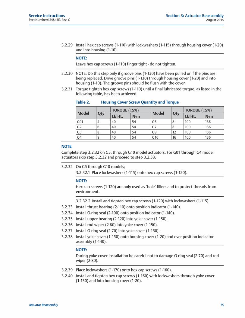
3.2.31 Torque tighten hex cap screws (1-110) until a final lubricated torque, as listed in the following table, has been achieved.
Table 2. Housing Cover Screw Quantity and Torque
Model QtyTORQUE (±5%)
Model QtyTORQUE (±5%)
Lbf-ft. N-m Lbf-ft. N-mG01 4 40 54 G5 8 100 136G2 6 40 54 G7 8 100 136G3 8 40 54 G8 12 100 136G4 8 40 54 G10 16 100 136
NOTE: Complete step 3.2.32 on G5, through G10 model actuators. For G01 through G4 model actuators skip step 3.2.32 and proceed to step 3.2.33.
3.2.32 On G5 through G10 models;
3.2.32.1 Place lockwashers (1-115) onto hex cap screws (1-120).
NOTE: Hex cap screws (1-120) are only used as "hole" fillers and to protect threads from environment.
3.2.32.2 Install and tighten hex cap screws (1-120) with lockwashers (1-115).
3.2.33 Install thrust bearing (2-110) onto position indicator (1-140).
3.2.34 Install O-ring seal (2-100) onto position indicator (1-140).
3.2.35 Install upper bearing (2-120) into yoke cover (1-150).
3.2.36 Install rod wiper (2-80) into yoke cover (1-150).
3.2.37 Install O-ring seal (2-70) into yoke cover (1-150).
3.2.38 Install yoke cover (1-150) onto housing cover (1-20) and over position indicator assembly (1-140).
NOTE: During yoke cover installation be careful not to damage O-ring seal (2-70) and rod wiper (2-80).
3.2.39 Place lockwashers (1-170) onto hex cap screws (1-160).
3.2.40 Install and tighten hex cap screws (1-160) with lockwashers through yoke cover (1-150) and into housing cover (1-20).

August 2015Service Instructions
Part Number:124843E, Rev. C
16
Section 3: Actuator Reassembly
Actuator Reassembly
3.2.41 Vent check assembly installation as follows:
3.2.41.1 G01, G2 and G3 housing (1-10) using pipe sealant install one vent check assembly (13) into the front of housing (1-10).
3.2.41.2 G01, G2 and G3 housing cover (1-20) using pipe sealant install one vent check assemble (13) into the top area of housing cover (1-20).
3.2.41.3 G4 through G10 housing (1-10) using pipe sealant install two vent check assemblies (13) into the front of housing (1-10).
3.2.42 NOTE: Refer to Section 2 step 2.3.3 for correct position indicator placement. Install position indicator (1-220) over the exposed shaft of position indicator assembly (1-140).
3.2.43 Install stop screw nuts (1-190) onto stop screws (1-180).
3.2.44 Install O-ring (2-90) onto stop screws (1-180).
3.2.45 Install two stop screws (1-180) into two stop screw holes on the front of housing (1-10).
3.2.46 Adjust both stop screws (1-180) back to settings recorded earlier in Section 2 at step 2.3.2.
3.2.47 Tighten both stop screw nuts (1-190) securely.
3.3 Pneumatic Power Module Reassembly
NOTES: 1. For early model G2 and G3 actuators with double nuts on the power module use section 3.4 for reassembly.
2. Refer to Section 2 step 2.1.3 for the correct installation location for piston rod (3-40). 3. THE ACTUATOR MUST BE IN THE APPROPRIATE OVERTRAVEL POSITION. Confirm over- travel position by observing the guide block (1-30) is against the inner wall of housing (1-10).
3.3.1 Lubricate piston rod (3-40) and insert through the side of housing (1-10).
3.3.1.1 G2 through G10 screw piston rod (3-40) onto extension rod assembly (1-50).
3.3.1.2 G01 screw piston rod (3-40) onto guide block (1-30).
3.3.2 Torque tighten piston rod (3-40) to the lubricated torque as listed in the following table.
Table 3. Piston Rod Torque Information
Housing Model
TORQUE (±5%) Housing Model
TORQUE (±5%)
Lbf-ft. N-m Lbf-ft. N-mG01 50 122 G5 240 325G2 90 122 G7 240 325G3 90 122 G8 240 325G4 240 325 G10 240 325
3.3.3 Refer to assembly drawing page 2 of 2 Detail "C". Install one rod wiper (4-10) into inner end cap (3-10).
3.3.4 Install one rod bushing (4-20) into inner end cap (3-10).
3.3.5 Coat one Polypak seal (4-30) with lubricant and install, lip first, into inner end cap (3-10).
Service InstructionsPart Number:124843E, Rev. C August 2015
17
Section 3: Actuator Reassembly
Actuator Reassembly
CAUTION: POLYPAK SEAL FACING PISTON SIDEInstall the Polypak seal with energizer ring facing outboard side (away from housing).
3.3.6 Install one o-ring seal (4-90) into seal groove located on the inboard face of inner end cap (3-10).
3.3.7 Install inner end cap (3-10) on to housing (1-10).
NOTE: The pressure inlet port should be positioned in the same position as recorded in section 2.2 step 2.2.1.
3.3.8 Place lockwashers (3-110) onto hex cap screws (3-100).
3.3.9 Install hex cap screws (3-100), with lockwashers, through housing (1-10) and into inner end cap (3-10).
3.3.10 Refer to assembly drawing page 2 of 2 Detail "D". Install one O-ring seal (4-70) into the seal groove in piston rod (3-40).
3.3.11 Apply lubricant to two sets of rod T-seal components (4-50).
NOTE: The T-seal is composed of one rubber seal and two split skive-cut back-up rings.
3.3.11.1 Install two sets of rod T-seals (4-50) into the internal diameter seal grooves of piston (3-30).
3.3.11.2 Install a back-up ring on each side of the T-seal.
3.3.11.3 When installing the back-up rings, do not align the skive-cuts.
3.3.11.4 If the back-up rings are too long and the rings overlap beyond the skive-cuts, then the rings must be trimmed with a razor sharp instrument.
3.3.12 Install two split ring halves (3-50) into the inner most groove in piston rod (3-40) and retain by installing the recessed area of piston (3-30) onto the piston rod and over the two split ring halves (3-50).
3.3.13 Install two split ring halves (3-50) into the piston rod, in front of the piston installed in the previous step, and retain with retainer ring (3-60).
3.3.14 Install one O-ring seal (4-40) onto the outer diameter seal groove of inner end cap (3-10).
3.3.15 Coat one D-ring seal (4-60) with lubricant and install into the piston external seal groove.
NOTE: The flat side of the D-ring seal go down into the seal groove.
3.3.16 Coat two tie bars (3-20) with lubricant and install by carefully pushing tie bars through piston (3-30) and rod T-seal (4-50).
3.3.17 Screw tie bars (3-20) into inner end cap (3-10) and tighten until the threads bottom out.
3.3.18 Refer to assembly drawing page 2 of 2 Detail "E". Coat two O-ring seals (4-80) with lubricant and install into outer end cap (3-80).
3.3.19 Apply lubricant to one O-ring seal (4-40) and install into the outer diameter O-ring groove of outer end cap (3-80).
3.3.20 Apply lubricant to the bore of cylinder (3-70).
August 2015Service Instructions
Part Number:124843E, Rev. C
18
Section 3: Actuator Reassembly
Actuator Reassembly
CAUTION: CAREFULLY INSTALL CYLINDERIf needed, when installing the cylinder, hammer on the end of the cylinder only with a non metallic object.
3.3.21 Install lubricated cylinder (3-70) over piston (3-30) and onto inner end cap (3-10). When installing the cylinder over the piston seal tilt cylinder 15° to 30° degrees to piston rod.
3.3.22 Install outer end cap (3-80) over tie bars (3-20) and into cylinder (3-70).
NOTE: The pressure inlet port should be positioned in the same position as recorded in Section 2 step 2.2.1.
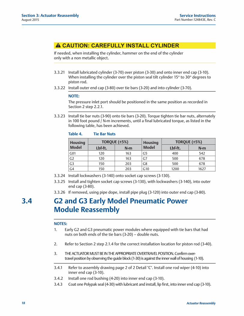
3.3.23 Install tie bar nuts (3-90) onto tie bars (3-20). Torque tighten tie bar nuts, alternately in 100 foot pound / N-m increments, until a final lubricated torque, as listed in the following table, has been achieved.
Table 4. Tie Bar Nuts
Housing Model
TORQUE (±5%) Housing Model
TORQUE (±5%)
Lbf-ft. N-m Lbf-ft. N-mG01 120 163 G5 400 542G2 120 163 G7 500 678G3 150 203 G8 500 678G4 150 203 G10 1200 1627
3.3.24 Install lockwashers (3-140) onto socket cap screws (3-130).
3.3.25 Install and tighten socket cap screws (3-130), with lockwashers (3-140), into outer end cap (3-80).
3.3.26 If removed, using pipe dope, install pipe plug (3-120) into outer end cap (3-80).
3.4 G2 and G3 Early Model Pneumatic Power Module Reassembly
NOTES: 1. Early G2 and G3 pneumatic power modules where equipped with tie bars that had nuts on both ends of the tie bars (3-20) – double nuts. 2. Refer to Section 2 step 2.1.4 for the correct installation location for piston rod (3-40). 3. THE ACTUATOR MUST BE IN THE APPROPRIATE OVERTRAVEL POSITION. Confirm over- travel position by observing the guide block (1-30) is against the inner wall of housing (1-10).
3.4.1 Refer to assembly drawing page 2 of 2 Detail "C". Install one rod wiper (4-10) into inner end cap (3-10).
3.4.2 Install one rod bushing (4-20) into inner end cap (3-10).
3.4.3 Coat one Polypak seal (4-30) with lubricant and install, lip first, into inner end cap (3-10).
Service InstructionsPart Number:124843E, Rev. C August 2015
19
Section 3: Actuator Reassembly
Actuator Reassembly
CAUTION: INSTALL POLYPAK SEAL CORRECTLYInstall the Polypak seal with energizer ring facing outboard side of inner end cap (3-10).
3.4.4 Install piston rod (3-40) through inner end cap (3-10).
NOTE: The piston rod end with retainer grooves to be on the outboard side of inner end cap (3-10).
NOTE:Piston will be torque tighten when installed into the drive module refer to Section 5 step 5.2.5.
3.4.5 Apply lubricant to two sets of rod T-seal components (4-50).
NOTE: The T-seal is composed of one rubber seal and two split skive-cut back-up rings.
3.4.5.1 Install two sets of rod T-seals (4-50) into the internal diameter seal grooves of piston (3-30).
3.4.5.2 Install a back-up ring on each side of the T-seal.
3.4.5.3 When installing the back-up rings, do not align the skive-cuts.
3.4.5.4 If the back-up rings are too long and the rings overlap beyond the skive-cuts, then the rings must be trimmed with a razor sharp instrument.
3.4.6 Coat one D-ring seal (4-60) with lubricant and install into the piston external seal groove.
NOTE: The flat side of the D-ring seal goes down into the seal groove.
3.4.7 Install piston (3-30) onto piston rod (3-40).
NOTE: The cast rib side of the piston is to be facing away from the outboard side of inner end cap (3-10) or position piston (3-30) on the piston rod so that the retainer grooves are on the out board side of the piston.
3.4.8 Refer to assembly drawing page 2 of 2 Detail "D". Install O-ring seal (4-70) into the seal groove in the outboard end of piston rod (3-40).
3.4.9 Install two split ring halves (3-50) into the outer most groove in piston rod (3-40) and retain by installing the recessed area of piston (3-30) over the two split halves (3-50).
3.4.10 Install two split ring halves (3-50) into the piston rod, in back of the piston and retain with retainer ring (3-60).
3.4.11 Coat two tie bars (3-20) with lubricant and install by carefully pushing tie bars through piston (3-30) and rod T-seal (4-50).
3.4.12 Install two tie bar O-ring seals (4-80) onto the inboard end of tie bars (3-20) and into the O-ring grooves provided.
August 2015Service Instructions
Part Number:124843E, Rev. C
20
Section 3: Actuator Reassembly
Actuator Reassembly
3.4.13 Insert the tie bars through inner end cap (3-10) and screw hex nuts (3-90) onto inboard end of the tie bars.
NOTE: Screw the tie bars through the hex nuts (3-90) until one complete thread is exposed.
3.4.14 Refer to assembly drawing page 2 of 2 Detail "E". Install two tie bar O-ring seals (4-80) onto the outboard end of tie bars (3-20) and into the O-ring grooves provided.
3.4.15 Apply lubricant to one O-ring seal (4-40) and install into the outer diameter O-ring groove of outer end cap (3-80).
3.4.16 Apply lubricant to the bore of cylinder (3-70).
CAUTION: CAREFULLY INSTALL CYLINDERIf needed, when installing the cylinder, hammer on the end of the cylinder only with a non-metallic object.
3.4.17 Install lubricated cylinder (3-70) over piston (3-30) and onto inner end cap (3-10). When installing the cylinder over the piston seal tilt cylinder 15° to 30° degrees to piston rod.
3.4.18 Install outer end cap (3-80) over tie bars (3-20) and into cylinder (3-70).
NOTE: The pressure inlet port should be positioned in the same position as recorded in section 2.2 step 2.2.1.
3.4.19 Install tie bar nuts (3-90) onto tie bars (3-20). Torque tighten tie bar nuts (3-90) as follows:
3.4.19.1 G2 model actuators torque to 120 Lbf-ft. / 163 N-m (±5 % Percent) lubricated.
3.4.19.2 G3 model actuators torque to 150 Lbf-ft. / 203 N-m (±5% Percent) lubricated.
3.4.20 Install lockwashers (3-140) onto socket cap screws (3-130).
3.4.21 Install and tighten socket cap screws (3-130), with lockwashers (3-140), into outer end cap (3-80).
3.4.22 Install pneumatic power module per Section 5 steps 5.2.
3.5 M11 Hydraulic Override Cylinder Reassembly
NOTE: Review Section 3.1 General Reassembly before proceeding with the M11 hydraulic override cylinder reassembly.
Service InstructionsPart Number:124843E, Rev. C August 2015
21
Section 3: Actuator Reassembly
Actuator Reassembly
NOTE:In Section 3.5 where the step indicates to "lubricate, coat or apply fluid", use hydraulic fluid, as identified in Section 1 step 1.6.2, for lubricating the part being installed.
3.5.1 Lubricate piston rod (7-40) with fluid.
3.5.2 Install O-ring seal (8-70) into the seal groove in piston rod (7-40).
3.5.3 Install two split ring halves (7-50) into the inner most groove in piston rod (7-40) and retain with one retainer ring (7-60).
3.5.4 Install piston (7-30) onto piston rod (7-40) and up against split rings install in step 3.5.3.
3.5.5 Install two split ring halves (7-50) into the outer most groove in piston rod (7-40) and retain with one retainer ring (7-60).
3.5.6 Apply fluid to the bore of cylinder (7-70).
3.5.7 Coat one piston bearing (8-45) with fluid and install into the piston external seal groove.
3.5.8 Install piston (7-30), with piston rod (7-40), into cylinder (7-70) leave the inner most piston seal groove outside of the cylinder.
3.5.9 Coat one piston seal (8-60) with fluid and install into the piston external seal groove.
CAUTION: INSTALL PISTON SEAL CORRECTLYInstall the piston seal with energizer ring facing outside edge of piston (7-30).
3.5.10 Push the piston through the cylinder (7-70) until the outboard piston seal groove is exposed.
NOTE:
To move the piston (7-30) through the bore of cylinder (7-70) may require mechanical assistance.
3.5.11 Coat one piston seal (8-60) with fluid and install into the piston external seal groove.
3.5.12 Refer to assembly drawing sheet 2 Detail "C". Coat Polypak seal (8-30) with hydraulic fluid and install; lip first, into inner end cap (7-10).
CAUTION: INSTALL POLYPAK SEAL CORRECTLYInstall the Polypak seal with energizer ring facing piston side of inner end cap (7-10).
3.5.13 Install rod bushing (8-20) into inner end cap (7-10).
3.5.14 Install rod wiper (8-10) into inner end cap (7-10).
3.5.15 Install one O-ring seal (8-90) into inboard face of inner end cap (7-10).
3.5.16 Install inner end cap (7-10) onto piston rod (7-40).
3.5.17 Install two tie bars (7-20) into inner end cap (7-10).
NOTE: The tie bars should be installed across from each other. Refer to the CAUTION after step 3.5.20.
August 2015Service Instructions
Part Number:124843E, Rev. C
22
Section 3: Actuator Reassembly
Actuator Reassembly
3.5.18 Install one O-ring seal (8-40) into inboard face of outer end cap (7-80).
3.5.19 Install outer end cap (7-80) into open end of cylinder (7-70).
NOTE: The pressure inlet ports of the inner and outer end caps should be positioned in the same position as recorded in Section 2 step 2.4.3.
3.5.20 Install the remaining tie bars (7-20) through outer end cap (7-80) and into inner end cap (7-10). Refer to the following CAUTION:
CAUTION: INSTALL TIE BARS CORRECTLYAssemble tie bars (7-20) into inner end cap (7-10) a minimum engagement of one tie bar thread diameter. Insure that three to four threads are equally exposed beyond the tie bar nuts (7-90) at the outer end cap (7-80).
3.5.21 Install lockwashers (7-95) onto tie bars (7-20) and up against outer end cap (7-80).
3.5.22 Install hex nuts (7-90) onto tie bars (7-20) and up against lockwashers (7-95).
3.5.23 Torque tighten hex nuts (7-90) until a final lubricated torque, as listed in the following table, has been achieved.
Table 5. Tie Bar Nuts (3-90)
Housing Model
TORQUE (±5%) Housing Model
TORQUE (±5%)
Lbf-ft. N-m Lbf-ft. N-mG01 70 95 G5 385 522G2 70 95 G7 580 786G3 70 95 G8 580 786G4 135 183 G10 1000 1356
3.5.24 Torque tighten piston rod (3-40) per the chart in Section 5.4 step 5.4.5.
3.5.25 Install the M11 Hydraulic Override Cylinder per Section 5 step 5.4.
3.6 Actuator Testing3.6.1 Leakage Test - All areas where leakage to atmosphere may occur are to be checked,
using a commercial leak testing solution.
CAUTION: DO NOT EXCEED MAXIMUM PRESSUREPressure applied to the actuator is not to exceed the maximum operating pressure rating listed on the actuator name tag. Test the actuator using a properly adjusted self relieving regulator, with gauge.
Service InstructionsPart Number:124843E, Rev. C August 2015
23
Section 3: Actuator Reassembly
Actuator Reassembly
3.6.2 Cycle the actuator five times at the nominal operating pressure (NOP) as listed on the actuator name tag or the customer's normal actuator supply pressure. If excessive leakage across the pistons is noted, generally a bubble which breaks three seconds or less after starting to form, cycle the actuator five times as this will allow the seals to seek their proper service condition.
NOTE: If excessive leakage across the piston remains, the actuator must be disassembled and the cause of leakage must be determined and corrected.
3.6.3 Apply NOP pressure to the pressure port in inner end cap (3-10) and allow the actuator to stabilize.
3.6.4 Apply a commercial leak testing solution to the following areas:
3.6.4.1 Joint between inner end cap (3-10) and cylinder (3-70). This checks cylinder to inner end cap O-ring seal.
3.6.4.2 The port hole in the outer end cap (3-80). This checks the piston seal to cylinder (3-70), O-ring seal (4-70), and rod seal (4-50).
3.6.4.3 The vent check port hole in housing. This checks Polypak seal (4-30) that seals piston rod (3-40) to inner end cap (3-10).
3.6.4.4 Remove pressure from the pressure inlet port.
3.6.5 If an actuator was disassembled and repaired, the above leakage test must be performed again.
3.6.6 Shell Pressure Test – Optional pressure test could be performed on PED certified actuator by applying pressure to both sides of the piston simultaneously for a period of two (2) minutes. If any leakage occurs across a static seal, the unit must be disassembled and the cause of leakage determined and corrected.
WARNING: PED PRESSURE TESTINGThe actuators main pressure bearing parts will be tested in controlled conditions in accordance with the requirement of PED by pressuring both sides of the piston to avoid damage and over torquing of the actuator components. If further future testing in the field is necessary, Emerson should be contacted for guidance.
August 2015Service Instructions
Part Number:124843E, Rev. C
24
Section 4: Field Conversions
Field Conversions
Section 4: Field Conversions
4.1 Construction Reversal (Exchange Module Locations)4.1.1 Remove pneumatic power module per Section 5.1.
4.1.2 Remove M11 hydraulic override cylinder per Section 5.3.
4.1.3 Using Section 5.1 reinstall the pneumatic power module onto the opposite end of housing (1-10) as it was previously located.
4.1.4 Using Section 5.3 reinstall the M11 hydraulic override cylinder onto the opposite end of housing (1-10), as it was previously located.
Service InstructionsPart Number:124843E, Rev. C August 2015
25
Section 5: Module Removal and Installation
Module Removal and Installation
Section 5: Module Removal and Installation
5.1 Pneumatic Power Module Removal
CAUTION: USE HEAVY DUTY SUPPORT EQUIPMENTDue to the weight and size of power module, heavy duty support equipment will be required when removing power module from the actuator housing. Refer to Section 6 for pneumatic power module weights.
5.1.1 Remove pipe plug (3-120) from outer end cap (3-80).
5.1.2 Remove hex cap screws (3-100) with lockwashers (3-110) from housing (1-10).
5.1.3 Using a male square drive extension, go through outer end cap (3-80) and unscrew piston rod (3-40) from the drive module housing (1-10).
NOTE: When removing power module from housing (1-10) be careful not to lose O-ring seal (4-90).
5.1.4 Remove power module from actuator housing (1-10).
5.2 Pneumatic Power Module Installation
NOTE: Reinstall the power module onto the opposite side of housing (1-10) as it was previously located.
5.2.1 Check to verify that O-ring seal (4-90) is properly seated in its seal groove located on the housing side of inner end cap (3-10).
NOTE: G2 and G3 models confirm that the two inboard hex nuts (3-90) flats are aligned to fit into the slot located in the end of housing (1-10).
5.2.2 Using lifting equipment move the power module up to housing (1-10) and install as follows: Use step 5.2.3 for G01 and step 5.2.4 for G2 through G10 actuator models.
5.2.3 G01 MODEL ACTUATORS:
5.2.3.1 Align piston rod (3-40) with threads in the guide block (1-30).
5.2.3.2 Using a male square drive extension, go through outer end cap (3-80) and screw piston rod (3-40) into guide block (1-30).
WARNING: DO NOT CROSS-THREAD PISTON RODWhen screwing piston rod into guide block (3-30) make certain that the piston rod and guide block threads do not cross-thread.
August 2015Service Instructions
Part Number:124843E, Rev. C
26
Section 5: Module Removal and Installation
Module Removal and Installation
5.2.4 G2 THROUGH G10 MODEL ACTUATORS:
5.2.4.1 Align piston rod (3-40) with extension rod assembly (1-50).
5.2.4.2 Using a male square drive extension, go through outer end cap (3-80) and screw piston rod (3-40) into extension rod assembly (1-50).
WARNING: DO NOT CROSS-THREAD PISTON RODWhen screwing piston rod into extension rod assembly (1-50) make certain that the piston rod and extension rod assembly threads do not cross-thread.
5.2.5 Torque tighten piston rod (3-40) as follows:
5.2.5.1 G01 model actuators torque to 50 Lbf-ft. / 68 N-m (±5 % Percent) lubricated.
5.2.5.2 G2 and G3 model actuators torque to 90 Lbf-ft. / 122 N-m (±5% Percent) lubricated.
5.2.5.3 G4 through G10 model actuators torque to 240 FT lb / 325 N-m (±5% Percent) lubricated.
5.2.6 Install lock washers (3-110) onto hex cap screws (3-100).
5.2.7 Install and tighten hex cap screws (3-100), with lockwashers, through housing (1-10) and into inner end cap (3-10).
5.2.8 Using pipe dope, install pipe plug (3-120) into outer end cap (3-80).
5.3 M11 Hydraulic Overrides Cylinder Removal
NOTE: Review section 2.1 General Disassembly before proceeding with the M11 Hydraulic Override Cylinder disassembly.
5.3.1 Remove O-ring plug (7-120) from outer end cap (7-80).
5.3.2 Using a male square drive extension, go through outer end cap (7-80); unscrew piston rod (7-40) from the drive module housing (1-10).
WARNING: USE PROPER LIFTING EQUIPMENTUse suitable lifting equipment to support the cylinder assembly.
5.3.3 Remove hex cap screws (7-115), with lockwashers (7-110), from inner end cap (7-10).
5.3.4 Remove hex nuts (7-105) from hex cap screws (7-100).
5.3.5 Remove M11 hydraulic override cylinder from actuator housing (1-10).
5.4 M11 Hydraulic Override Cylinder Installation
NOTE: Review Section 3.1 General Reassembly before proceeding with M11 Hydraulic Override Cylinder installation.
Service InstructionsPart Number:124843E, Rev. C August 2015
27
Section 5: Module Removal and Installation
Module Removal and Installation
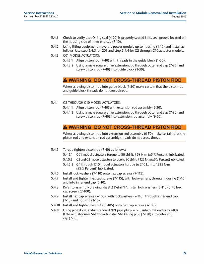
5.4.1 Check to verify that O-ring seal (4-90) is properly seated in its seal groove located on the housing side of inner end cap (7-10).
5.4.2 Using lifting equipment move the power module up to housing (1-10) and install as follows: Use step 5.4.3 for G01 and step 5.4.4 for G2 through G10 actuator models.
5.4.3 G01 MODEL ACTUATORS:
5.4.3.1 Align piston rod (7-40) with threads in the guide block (1-30).
5.4.3.2 Using a male square drive extension, go through outer end cap (7-80) and screw piston rod (7-40) into guide block (1-30).
WARNING: DO NOT CROSS-THREAD PISTON RODWhen screwing piston rod into guide block (1-30) make certain that the piston rod and guide block threads do not cross-thread.
5.4.4 G2 THROUGH G10 MODEL ACTUATORS:
5.4.4.1 Align piston rod (7-40) with extension rod assembly (9-50).
5.4.4.2 Using a male square drive extension, go through outer end cap (7-80) and screw piston rod (7-40) into extension rod assembly (9-50).
WARNING: DO NOT CROSS-THREAD PISTON RODWhen screwing piston rod into extension rod assembly (9-50) make certain that the piston rod and extension rod assembly threads do not cross-thread.
5.4.5 Torque tighten piston rod (7-40) as follows:
5.4.5.1 G01 model actuators torque to 50 Lbf-ft. / 68 N-m (±5 % Percent) lubricated.
5.4.5.2 G2 and G3 model actuators torque to 90 Lbf-ft. / 122 N-m (±5 % Percent) lubricated.
5.4.5.3 G4 through G10 model actuators torque to 240 Lbf-ft. / 325 N-m (±5 % Percent) lubricated.
5.4.6 Install lock washers (7-110) onto hex cap screws (7-115).
5.4.7 Install and tighten hex cap screws (7-115), with lockwashers, through housing (1-10) and into inner end cap (7-10).
5.4.8 Refer to assembly drawing sheet 2 Detail "F". Install lock washers (7-110) onto hex cap screws (7-100).
5.4.9 Install hex cap screws (7-100), with lockwashers (7-110), through inner end cap (7-10) and housing (1-10).
5.4.10 Install and tighten hex nuts (7-105) onto hex cap screws (7-100).
5.4.11 Using pipe dope, install standard NPT pipe plug (7-120) into outer end cap (7-80). If the actuator uses SAE threads install SAE O-ring plug (7-120) into outer end cap (7-80).
August 2015Service Instructions
Part Number:124843E, Rev. C
28
Section 5: Module Removal and Installation
Module Removal and Installation
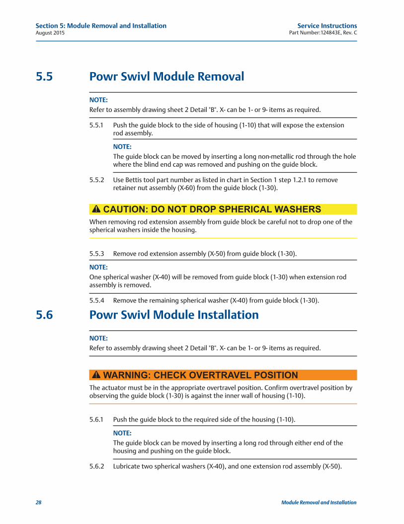
5.5 Powr Swivl Module Removal
NOTE: Refer to assembly drawing sheet 2 Detail "B". X- can be 1- or 9- items as required.
5.5.1 Push the guide block to the side of housing (1-10) that will expose the extension rod assembly.
NOTE: The guide block can be moved by inserting a long non-metallic rod through the hole where the blind end cap was removed and pushing on the guide block.
5.5.2 Use Bettis tool part number as listed in chart in Section 1 step 1.2.1 to remove retainer nut assembly (X-60) from the guide block (1-30).
CAUTION: DO NOT DROP SPHERICAL WASHERSWhen removing rod extension assembly from guide block be careful not to drop one of the spherical washers inside the housing.
5.5.3 Remove rod extension assembly (X-50) from guide block (1-30).
NOTE: One spherical washer (X-40) will be removed from guide block (1-30) when extension rod assembly is removed.
5.5.4 Remove the remaining spherical washer (X-40) from guide block (1-30).
5.6 Powr Swivl Module Installation
NOTE: Refer to assembly drawing sheet 2 Detail "B". X- can be 1- or 9- items as required.
WARNING: CHECK OVERTRAVEL POSITIONThe actuator must be in the appropriate overtravel position. Confirm overtravel position by observing the guide block (1-30) is against the inner wall of housing (1-10).
5.6.1 Push the guide block to the required side of the housing (1-10).
NOTE: The guide block can be moved by inserting a long rod through either end of the housing and pushing on the guide block.
5.6.2 Lubricate two spherical washers (X-40), and one extension rod assembly (X-50).

Service InstructionsPart Number:124843E, Rev. C August 2015
29
Section 5: Module Removal and Installation
Module Removal and Installation
5.6.3 Install one spherical washer (X-40) into the side of guide block (1-30).
NOTE: The spherical side of washer (X-40) will be facing to the outside of guide block (1-30).
5.6.4 Install second spherical washer (X-40) over threaded end of extension rod assembly (X-50).
NOTE: The spherical side of the washer will go on the extension rod assembly facing the head of the extension rod assembly.
5.6.5 Install extension rod assembly (X-50) into right of guide block (1-30) and up against the first spherical washer (X-40).
5.6.6 Install extension retainer nut assembly (X-60) over extension rod assembly (X-50) and screw into guide block (1-30).
5.6.7 Tighten extension retainer nut assembly (X-60) until extension rod assembly (X-50) cannot move. Back off the extension retainer nut assembly (X-60) just enough to allow for extension rod assembly (X-50) to move freely.
August 2015Service Instructions
Part Number:124843E, Rev. C
30
Section 6: Actuator Support Information
Actuator Support Information
Section 6: Actuator Support Information
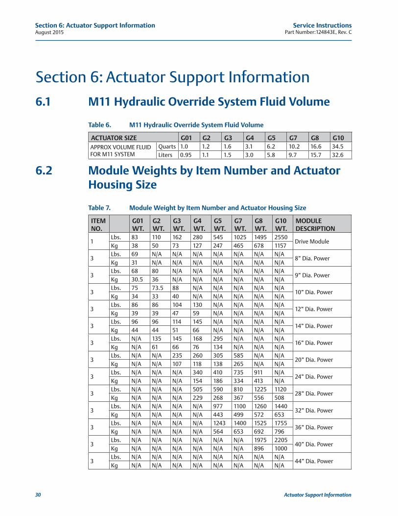
6.1 M11 Hydraulic Override System Fluid Volume
Table 6. M11 Hydraulic Override System Fluid Volume
ACTUATOR SIZE G01 G2 G3 G4 G5 G7 G8 G10APPROX VOLUME FLUID FOR M11 SYSTEM
Quarts 1.0 1.2 1.6 3.1 6.2 10.2 16.6 34.5Liters 0.95 1.1 1.5 3.0 5.8 9.7 15.7 32.6
6.2 Module Weights by Item Number and Actuator Housing Size
Table 7. Module Weight by Item Number and Actuator Housing Size
ITEM NO.
G01 WT.
G2 WT.
G3WT.
G4WT.
G5 WT.
G7 WT.
G8 WT.
G10 WT.
MODULE DESCRIPTION
1Lbs. 83 110 162 280 545 1025 1495 2550
Drive ModuleKg 38 50 73 127 247 465 678 1157
3Lbs. 69 N/A N/A N/A N/A N/A N/A N/A
8” Dia. PowerKg 31 N/A N/A N/A N/A N/A N/A N/A
3Lbs. 68 80 N/A N/A N/A N/A N/A N/A
9” Dia. PowerKg 30.5 36 N/A N/A N/A N/A N/A N/A
3Lbs. 75 73.5 88 N/A N/A N/A N/A N/A
10” Dia. PowerKg 34 33 40 N/A N/A N/A N/A N/A
3Lbs. 86 86 104 130 N/A N/A N/A N/A
12” Dia. PowerKg 39 39 47 59 N/A N/A N/A N/A
3Lbs. 96 96 114 145 N/A N/A N/A N/A
14” Dia. PowerKg 44 44 51 66 N/A N/A N/A N/A
3Lbs. N/A 135 145 168 295 N/A N/A N/A
16” Dia. PowerKg N/A 61 66 76 134 N/A N/A N/A
3Lbs. N/A N/A 235 260 305 585 N/A N/A
20” Dia. PowerKg N/A N/A 107 118 138 265 N/A N/A
3Lbs. N/A N/A N/A 340 410 735 911 N/A
24” Dia. PowerKg N/A N/A N/A 154 186 334 413 N/A
3Lbs. N/A N/A N/A 505 590 810 1225 1120
28” Dia. PowerKg N/A N/A N/A 229 268 367 556 508
3Lbs. N/A N/A N/A N/A 977 1100 1260 1440
32” Dia. PowerKg N/A N/A N/A N/A 443 499 572 653
3Lbs. N/A N/A N/A N/A 1243 1400 1525 1755
36” Dia. PowerKg N/A N/A N/A N/A 564 653 692 796
3Lbs. N/A N/A N/A N/A N/A N/A 1975 2205
40” Dia. PowerKg N/A N/A N/A N/A N/A N/A 896 1000
3Lbs. N/A N/A N/A N/A N/A N/A N/A N/A
44” Dia. PowerKg N/A N/A N/A N/A N/A N/A N/A N/A
Service InstructionsPart Number:124843E, Rev. C August 2015
31
Section 6: Actuator Support Information
Actuator Support Information
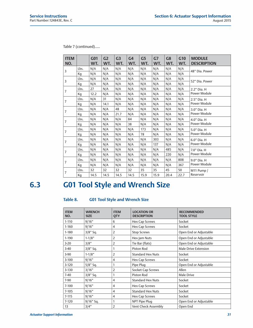
Table 7 (continued).....
ITEM NO.
G01 WT.
G2 WT.
G3WT.
G4WT.
G5 WT.
G7 WT.
G8 WT.
G10 WT.
MODULE DESCRIPTION
3Lbs. N/A N/A N/A N/A N/A N/A N/A N/A
48” Dia. PowerKg N/A N/A N/A N/A N/A N/A N/A N/A
3Lbs. N/A N/A N/A N/A N/A N/A N/A N/A
52” Dia. PowerKg N/A N/A N/A N/A N/A N/A N/A N/A
7Lbs. 27 N/A N/A N/A N/A N/A N/A N/A 2.2” Dia. H
Power ModuleKg 12.2 N/A N/A N/A N/A N/A N/A N/A
7Lbs. N/A 31 N/A N/A N/A N/A N/A N/A 2.5” Dia. H
Power ModuleKg N/A 14.1 N/A N/A N/A N/A N/A N/A
7Lbs. N/A N/A 48 N/A N/A N/A N/A N/A 3.0” Dia. H
Power ModuleKg N/A N/A 21.7 N/A N/A N/A N/A N/A
7Lbs. N/A N/A N/A 84 N/A N/A N/A N/A 4.0” Dia. H
Power ModuleKg N/A N/A N/A 38 N/A N/A N/A N/A
7Lbs. N/A N/A N/A N/A 173 N/A N/A N/A 5.0” Dia. H
Power ModuleKg N/A N/A N/A N/A 78 N/A N/A N/A
7Lbs. N/A N/A N/A N/A N/A 303 N/A N/A 6.0” Dia. H
Power ModuleKg N/A N/A N/A N/A N/A 137 N/A N/A
7Lbs. N/A N/A N/A N/A N/A N/A 485 N/A 7.0” Dia. H
Power ModuleKg N/A N/A N/A N/A N/A N/A 220 N/A
7Lbs. N/A N/A N/A N/A N/A N/A N/A 808 9.0” Dia. H
Power ModuleKg N/A N/A N/A N/A N/A N/A N/A 367
7Lbs. 32 32 32 32 35 35 45 50 M11 Pump /
ReservoirKg 14.5 14.5 14.5 14.5 15.9 15.9 20.4 22.7
6.3 G01 Tool Style and Wrench Size
Table 8. G01 Tool Style and Wrench Size
ITEM NO.
WRENCH SIZE
ITEM QTY
LOCATION OR DESCRIPTION
RECOMMENDED TOOL STYLE
1-110 9/16” 6 Hex Cap Screws Socket
1-160 9/16” 4 Hex Cap Screws Socket
1-180 3/8” Sq. 2 Stop Screws Open End or Adjustable
1-190 1-1/8” 2 Hex Jam Nuts Open End or Adjustable
3-20 3/8” 2 Tie Bar (flats) Open End or Adjustable
3-40 3/8” Sq. 1 Piston Rod Male Drive Extension
3-90 1-1/8” 2 Standard Hex Nuts Socket
3-100 9/16” 4 Hex Cap Screws Socket
3-120 5/8” Sq. 1 Pipe Plug Open End or Adjustable
3-130 3/16” 2 Socket Cap Screws Allen
7-40 3/8” Sq. 1 Piston Rod Male Drive
7-90 9/16” 4 Standard Hex Nuts Socket
7-100 9/16” 4 Hex Cap Screws Socket
7-105 9/16” 4 Standard Hex Nuts Socket
7-115 9/16” 4 Hex Cap Screws Socket
7-120 9/16” Sq. 1 NPT Pipe Plug Open End or Adjustable
13 3/4” 2 Vent Check Assembly Open End
August 2015Service Instructions
Part Number:124843E, Rev. C
32
Section 6: Actuator Support Information
Actuator Support Information
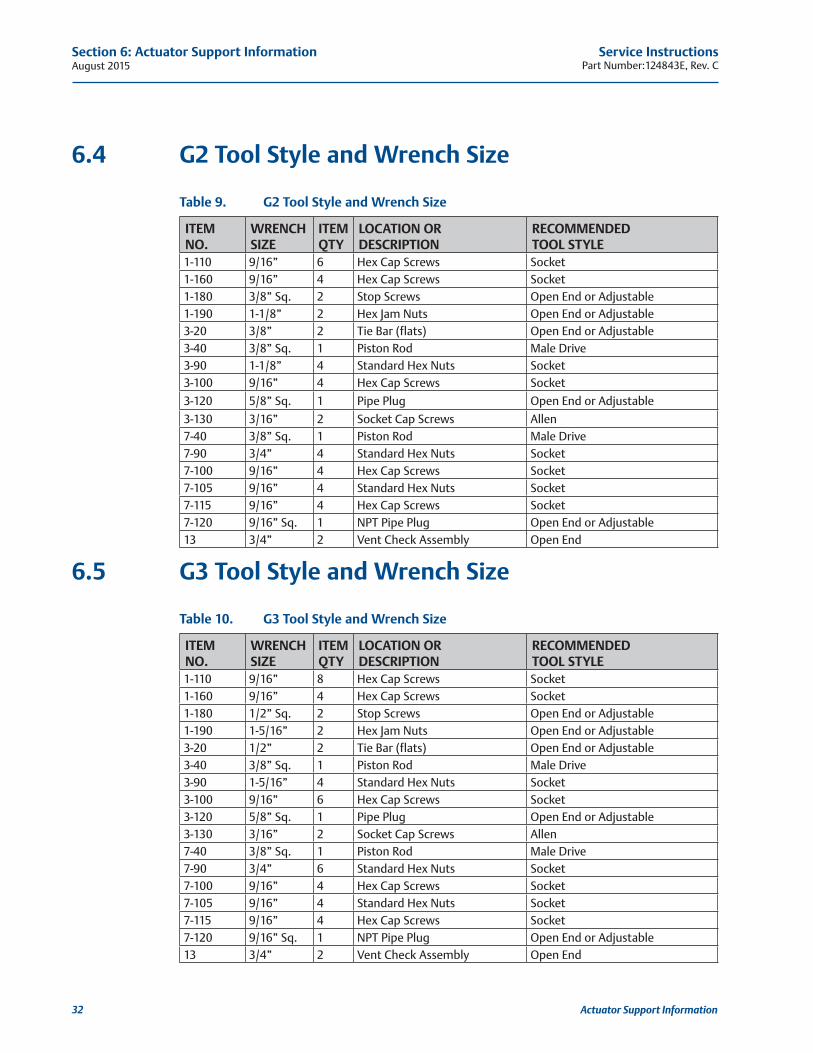
6.4 G2 Tool Style and Wrench Size
Table 9. G2 Tool Style and Wrench Size
ITEM NO.
WRENCHSIZE
ITEMQTY
LOCATION OR DESCRIPTION
RECOMMENDED TOOL STYLE
1-110 9/16” 6 Hex Cap Screws Socket1-160 9/16” 4 Hex Cap Screws Socket1-180 3/8” Sq. 2 Stop Screws Open End or Adjustable1-190 1-1/8” 2 Hex Jam Nuts Open End or Adjustable3-20 3/8” 2 Tie Bar (flats) Open End or Adjustable3-40 3/8” Sq. 1 Piston Rod Male Drive3-90 1-1/8” 4 Standard Hex Nuts Socket3-100 9/16” 4 Hex Cap Screws Socket
3-120 5/8” Sq. 1 Pipe Plug Open End or Adjustable
3-130 3/16” 2 Socket Cap Screws Allen7-40 3/8” Sq. 1 Piston Rod Male Drive7-90 3/4” 4 Standard Hex Nuts Socket7-100 9/16” 4 Hex Cap Screws Socket7-105 9/16” 4 Standard Hex Nuts Socket7-115 9/16” 4 Hex Cap Screws Socket7-120 9/16” Sq. 1 NPT Pipe Plug Open End or Adjustable13 3/4” 2 Vent Check Assembly Open End
6.5 G3 Tool Style and Wrench Size
Table 10. G3 Tool Style and Wrench Size
ITEM NO.
WRENCHSIZE
ITEMQTY
LOCATION OR DESCRIPTION
RECOMMENDED TOOL STYLE
1-110 9/16” 8 Hex Cap Screws Socket1-160 9/16” 4 Hex Cap Screws Socket1-180 1/2” Sq. 2 Stop Screws Open End or Adjustable1-190 1-5/16” 2 Hex Jam Nuts Open End or Adjustable3-20 1/2” 2 Tie Bar (flats) Open End or Adjustable3-40 3/8” Sq. 1 Piston Rod Male Drive3-90 1-5/16” 4 Standard Hex Nuts Socket3-100 9/16” 6 Hex Cap Screws Socket3-120 5/8” Sq. 1 Pipe Plug Open End or Adjustable3-130 3/16” 2 Socket Cap Screws Allen7-40 3/8” Sq. 1 Piston Rod Male Drive7-90 3/4” 6 Standard Hex Nuts Socket7-100 9/16” 4 Hex Cap Screws Socket7-105 9/16” 4 Standard Hex Nuts Socket7-115 9/16” 4 Hex Cap Screws Socket7-120 9/16” Sq. 1 NPT Pipe Plug Open End or Adjustable13 3/4” 2 Vent Check Assembly Open End
Service InstructionsPart Number:124843E, Rev. C August 2015
33
Section 6: Actuator Support Information
Actuator Support Information
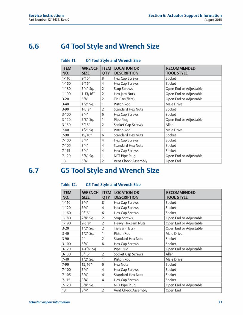
6.6 G4 Tool Style and Wrench Size
Table 11. G4 Tool Style and Wrench Size
ITEM NO.
WRENCHSIZE
ITEMQTY
LOCATION OR DESCRIPTION
RECOMMENDED TOOL STYLE
1-110 9/16” 8 Hex Cap Screws Socket1-160 9/16” 4 Hex Cap Screws Socket1-180 3/4” Sq. 2 Stop Screws Open End or Adjustable1-190 1-13/16” 2 Hex Jam Nuts Open End or Adjustable3-20 5/8” 2 Tie Bar (flats) Open End or Adjustable3-40 1/2” Sq. 1 Piston Rod Male Drive3-90 1-5/8” 2 Standard Hex Nuts Socket3-100 3/4” 6 Hex Cap Screws Socket3-120 5/8” Sq. 1 Pipe Plug Open End or Adjustable3-130 3/16” 2 Socket Cap Screws Allen7-40 1/2” Sq. 1 Piston Rod Male Drive7-90 15/16” 6 Standard Hex Nuts Socket7-100 3/4” 4 Hex Cap Screws Socket7-105 3/4” 4 Standard Hex Nuts Socket7-115 3/4” 4 Hex Cap Screws Socket7-120 5/8” Sq. 1 NPT Pipe Plug Open End or Adjustable13 3/4” 2 Vent Check Assembly Open End
6.7 G5 Tool Style and Wrench Size
Table 12. G5 Tool Style and Wrench Size
ITEM NO.
WRENCHSIZE
ITEMQTY
LOCATION OR DESCRIPTION
RECOMMENDED TOOL STYLE
1-110 3/4” 8 Hex Cap Screws Socket1-120 3/4” 4 Hex Cap Screws Socket1-160 9/16” 6 Hex Cap Screws Socket1-180 7/8” Sq. 2 Stop Screws Open End or Adjustable1-190 2-3/8” 2 Heavy Hex Jam Nuts Open End or Adjustable3-20 1/2” Sq. 2 Tie Bar (flats) Open End or Adjustable3-40 1/2” Sq. 1 Piston Rod Male Drive3-90 2” 2 Standard Hex Nuts Socket3-100 3/4” 8 Hex Cap Screws Socket3-120 1-1/8” Sq. 1 Pipe Plug Open End or Adjustable3-130 3/16” 2 Socket Cap Screws Allen7-40 1/2” Sq. 1 Piston Rod Male Drive7-90 15/16” 6 Hex Nuts Socket7-100 3/4” 4 Hex Cap Screws Socket7-105 3/4” 4 Standard Hex Nuts Socket7-115 3/4” 4 Hex Cap Screws Socket7-120 5/8” Sq. 1 NPT Pipe Plug Open End or Adjustable13 3/4” 2 Vent Check Assembly Open End
August 2015Service Instructions
Part Number:124843E, Rev. C
34
Section 6: Actuator Support Information
Actuator Support Information
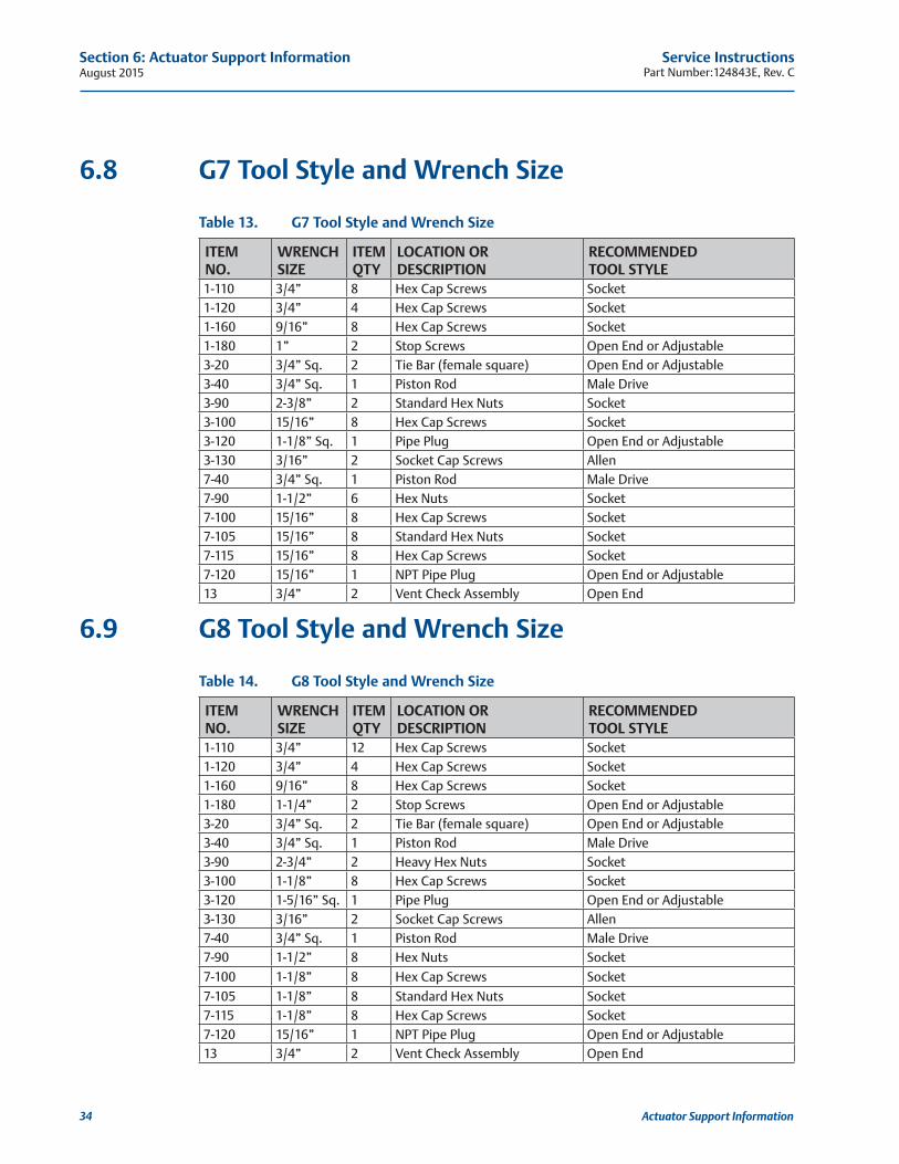
6.8 G7 Tool Style and Wrench Size
Table 13. G7 Tool Style and Wrench Size
ITEM NO.
WRENCHSIZE
ITEMQTY
LOCATION OR DESCRIPTION
RECOMMENDED TOOL STYLE
1-110 3/4” 8 Hex Cap Screws Socket1-120 3/4” 4 Hex Cap Screws Socket1-160 9/16” 8 Hex Cap Screws Socket1-180 1” 2 Stop Screws Open End or Adjustable3-20 3/4” Sq. 2 Tie Bar (female square) Open End or Adjustable3-40 3/4” Sq. 1 Piston Rod Male Drive3-90 2-3/8” 2 Standard Hex Nuts Socket3-100 15/16” 8 Hex Cap Screws Socket3-120 1-1/8” Sq. 1 Pipe Plug Open End or Adjustable3-130 3/16” 2 Socket Cap Screws Allen7-40 3/4” Sq. 1 Piston Rod Male Drive7-90 1-1/2” 6 Hex Nuts Socket7-100 15/16” 8 Hex Cap Screws Socket7-105 15/16” 8 Standard Hex Nuts Socket7-115 15/16” 8 Hex Cap Screws Socket7-120 15/16” 1 NPT Pipe Plug Open End or Adjustable13 3/4” 2 Vent Check Assembly Open End
6.9 G8 Tool Style and Wrench Size
Table 14. G8 Tool Style and Wrench Size
ITEM NO.
WRENCHSIZE
ITEMQTY
LOCATION OR DESCRIPTION
RECOMMENDED TOOL STYLE
1-110 3/4” 12 Hex Cap Screws Socket1-120 3/4” 4 Hex Cap Screws Socket1-160 9/16” 8 Hex Cap Screws Socket1-180 1-1/4” 2 Stop Screws Open End or Adjustable3-20 3/4” Sq. 2 Tie Bar (female square) Open End or Adjustable3-40 3/4” Sq. 1 Piston Rod Male Drive3-90 2-3/4” 2 Heavy Hex Nuts Socket3-100 1-1/8” 8 Hex Cap Screws Socket3-120 1-5/16” Sq. 1 Pipe Plug Open End or Adjustable3-130 3/16” 2 Socket Cap Screws Allen7-40 3/4” Sq. 1 Piston Rod Male Drive7-90 1-1/2” 8 Hex Nuts Socket
7-100 1-1/8” 8 Hex Cap Screws Socket
7-105 1-1/8” 8 Standard Hex Nuts Socket7-115 1-1/8” 8 Hex Cap Screws Socket7-120 15/16” 1 NPT Pipe Plug Open End or Adjustable13 3/4” 2 Vent Check Assembly Open End
Service InstructionsPart Number:124843E, Rev. C August 2015
35
Section 6: Actuator Support Information
Actuator Support Information
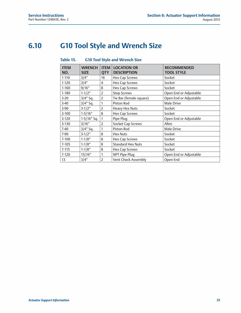
6.10 G10 Tool Style and Wrench Size
Table 15. G10 Tool Style and Wrench Size
ITEM NO.
WRENCHSIZE
ITEMQTY
LOCATION OR DESCRIPTION
RECOMMENDED TOOL STYLE
1-110 3/4” 16 Hex Cap Screws Socket1-120 3/4” 4 Hex Cap Screws Socket1-160 9/16” 8 Hex Cap Screws Socket1-180 1-1/2” 2 Stop Screws Open End or Adjustable3-20 3/4” Sq. 2 Tie Bar (female square) Open End or Adjustable3-40 3/4” Sq. 1 Piston Rod Male Drive3-90 3-1/2” 2 Heavy Hex Nuts Socket3-100 1-5/16” 8 Hex Cap Screws Socket3-120 1-5/16” Sq. 1 Pipe Plug Open End or Adjustable3-130 3/16” 2 Socket Cap Screws Allen7-40 3/4” Sq. 1 Piston Rod Male Drive7-90 3-1/2” 8 Hex Nuts Socket7-100 1-1/8” 8 Hex Cap Screws Socket7-105 1-1/8” 8 Standard Hex Nuts Socket7-115 1-1/8” 8 Hex Cap Screws Socket7-120 15/16” 1 NPT Pipe Plug Open End or Adjustable13 3/4” 2 Vent Check Assembly Open End
August 2015Service Instructions
Part Number:124843E, Rev. C
36
Section 7: Troubleshooting
Troubleshooting
Section 7: Troubleshooting
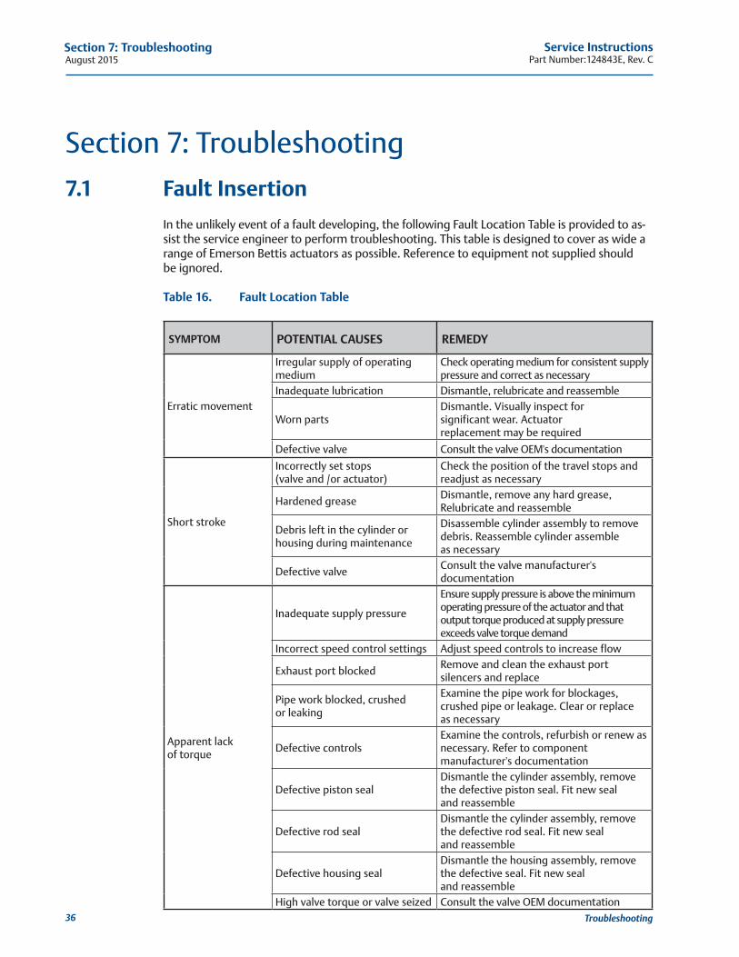
7.1 Fault InsertionIn the unlikely event of a fault developing, the following Fault Location Table is provided to as-sist the service engineer to perform troubleshooting. This table is designed to cover as wide a range of Emerson Bettis actuators as possible. Reference to equipment not supplied should be ignored.
Table 16. Fault Location Table
SYMPTOM POTENTIAL CAUSES REMEDY
Erratic movement
Irregular supply of operatingmedium
Check operating medium for consistent supply pressure and correct as necessary
Inadequate lubrication Dismantle, relubricate and reassemble
Worn partsDismantle. Visually inspect for significant wear. Actuator replacement may be required
Defective valve Consult the valve OEM's documentation
Short stroke
Incorrectly set stops(valve and /or actuator)
Check the position of the travel stops and readjust as necessary
Hardened greaseDismantle, remove any hard grease,Relubricate and reassemble
Debris left in the cylinder orhousing during maintenance
Disassemble cylinder assembly to remove debris. Reassemble cylinder assemble as necessary
Defective valveConsult the valve manufacturer'sdocumentation
Apparent lack of torque
Inadequate supply pressure
Ensure supply pressure is above the minimum operating pressure of the actuator and that output torque produced at supply pressure exceeds valve torque demand
Incorrect speed control settings Adjust speed controls to increase flow
Exhaust port blockedRemove and clean the exhaust port silencers and replace
Pipe work blocked, crushedor leaking
Examine the pipe work for blockages, crushed pipe or leakage. Clear or replace as necessary
Defective controlsExamine the controls, refurbish or renew as necessary. Refer to component manufacturer's documentation
Defective piston sealDismantle the cylinder assembly, remove the defective piston seal. Fit new seal and reassemble
Defective rod sealDismantle the cylinder assembly, remove the defective rod seal. Fit new seal and reassemble
Defective housing sealDismantle the housing assembly, remove the defective seal. Fit new seal and reassemble
High valve torque or valve seized Consult the valve OEM documentation
Service InstructionsPart Number:124843E, Rev. C August 2015
37
Section 7: Troubleshooting
Troubleshooting
7.2 Operational Test7.2.1 Full Stroke Test
The “Full Stroke Test” (“On-line”) must be performed to satisfy the PFDAVG (average probability of failure on demand) value. The full stroke test frequencies will be defined by the final installer to achieve the defined SIL level.
7.2.1.1 Procedure
7.2.1.1.1 Stroke the actuator/valve assembly two complete open/close cycles with complete closing of the valve.
7.2.1.1.2 Verify the open/close cycles functioned correctly (e.g. check locally, or automatically via Logic solver, the correct movement of the actuator/valve).
Upon successful completion of the above described Full Stroke Test procedure, the “Test Coverage” can be considered 99%.
7.2.2 Partial Stroke Test (when requested) The “Partial Stroke Test” (“On-line”) can be performed to improve the PFDAVG value and to satisfy PFDAVG (average probability of failure on demand) value. A typical partial stroke value is 15% of the stroke and the recommended test interval is about every one to three months.
7.2.2.1 Procedure
7.2.2.1.1 Operate the actuator/valve assembly for No° 1 open/close cycles 15% of the stroke.
7.2.2.1.2 Verify the partial stroke test functioned correctly (e.g. check locally, or automatically via logic solver, or via the PST system the correct movement of the actuator/valve was 15% of the stroke).
NOTE: The above test is only applicable on systems equipped with a partial stroke feature.
August 2015Service Instructions
Part Number:124843E, Rev. C
38
Section 8: Removal and Decommissioning
Removal and Decommissioning
Section 8: Removal and Decommissioning
8.1 Removal and Decommissioning
WARNING: FOLLOW PROPER PROCEDUREAlways follow safe work practices remove and disassemble G-Series actuator.
The below basic procedure should not supersede or replace any customer's plant safety or work procedures. If a conflict arises between this procedure and the customer's procedures, the differences should be resolved in writing between an authorized customer’s representative and an authorized Emerson/Bettis representative.
CAUTION: ISOLATE AND POWER OFF ACTUATORMake sure actuator is isolated before removing from valve. Turn OFF the power medium and bleed off all pressure first, including storage tank (if present). Next, bleed off pilot pressure, disconnect: pneumatic pressure supply, pilot tubing and electrical wiring (if equipped).
Before starting the disassembly, a large area should be created around the actuator so to allow any kind of movement.
Separate the parts composing the actuator according to their nature (ex. metallic, and plastic materials, fluids etc.) and send them to differentiated waste collection sites, as pro-vided for by the laws and provisions in force.
8.1.1 Drain tanks and remove tubing from actuator. Remove accessories (if equipped) and controls from actuator.
8.1.2 Remove all equipment mounted on top of actuator (limit switches, end of stroke valve, and relevant pneumatic/electric connection, etc.)
8.1.3 Remove mounting bolts and actuator is ready to be removed from valve.
For complete actuator tear down refer to Section 2 of the manual.
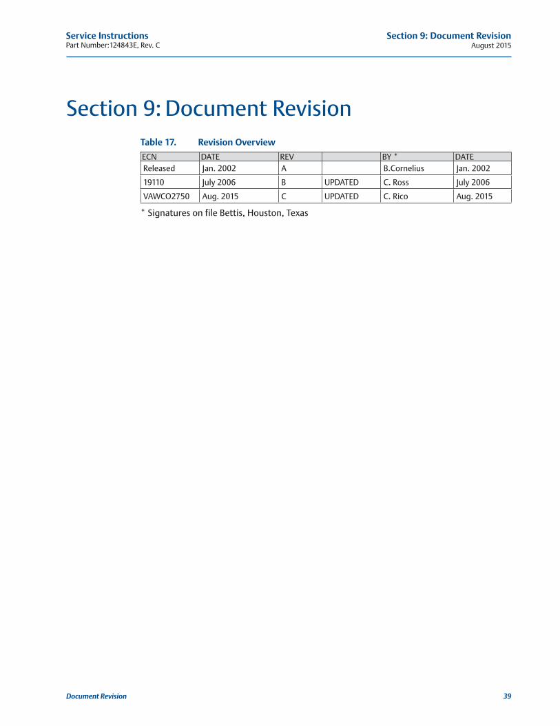
Service InstructionsPart Number:124843E, Rev. C August 2015
39
Section 9: Document Revision
Document Revision
Section 9: Document RevisionTable 17. Revision Overview
ECN DATE REV BY * DATEReleased Jan. 2002 A B.Cornelius Jan. 2002
19110 July 2006 B UPDATED C. Ross July 2006
VAWCO2750 Aug. 2015 C UPDATED C. Rico Aug. 2015
* Signatures on file Bettis, Houston, Texas
August 2015Service Instructions
Part Number:124843E, Rev. C
40
Appendix
Appendix
Appendix A: List of TablesTable 1. G-Series Models .................................................................................................. 3
Table 2. Housing Cover Screw Quantity and Torque ...................................................... 15
Table 3. Piston Rod Torque Information ......................................................................... 16
Table 4. Tie Bar Nuts ..................................................................................................... 18
Table 5. Tie Bar Nuts (3-90) ........................................................................................... 22
Table 6. M11 Hydraulic Override System Fluid Volume .................................................. 30
Table 7. Module Weight by Item Number and Actuator Housing Size ............................ 30
Table 8. G01 Tool Style and Wrench Size ........................................................................ 31
Table 9. G2 Tool Style and Wrench Size .......................................................................... 32
Table 10. G3 Tool Style and Wrench Size .......................................................................... 33
Table 11. G4 Tool Style and Wrench Size .......................................................................... 33
Table 12. G5 Tool Style and Wrench Size ......................................................................... 34
Table 13. G7 Tool Style and Wrench Size .......................................................................... 34
Table 14. G8 Tool Style and Wrench Size ......................................................................... 35
Table 15. G10 Tool Style and Wrench Size ....................................................................... 35
Table 16. Fault Location Table .......................................................................................... 36
Table 17. Revision Overview ............................................................................................. 39

Service InstructionsPart Number:124843E, Rev. C August 2015
41
Appendix
Appendix
Appendix B: List of Drawings
B.1 Part No. 115680, GXXXX-H Pneumatic Assembly Drawing, Sheet 1 of 2

August 2015Service Instructions
Part Number:124843E, Rev. C
42
Appendix
Appendix
B.2 Part No. 115680, GXXXX-H Pneumatic Assembly Drawing, Sheet 2 of 2
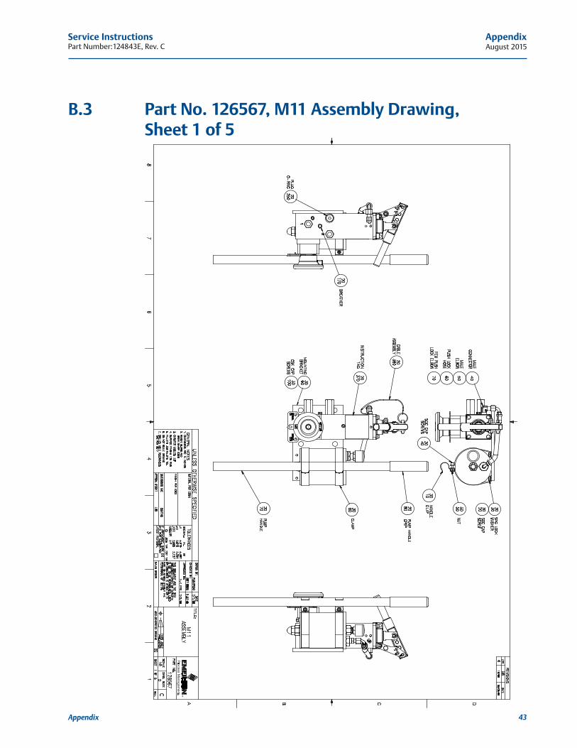
Service InstructionsPart Number:124843E, Rev. C August 2015
43
Appendix
Appendix
B.3 Part No. 126567, M11 Assembly Drawing, Sheet 1 of 5

August 2015Service Instructions
Part Number:124843E, Rev. C
44
Appendix
Appendix
B.4 Part No. 126567, M11 Assembly Drawing, Sheet 2 of 5
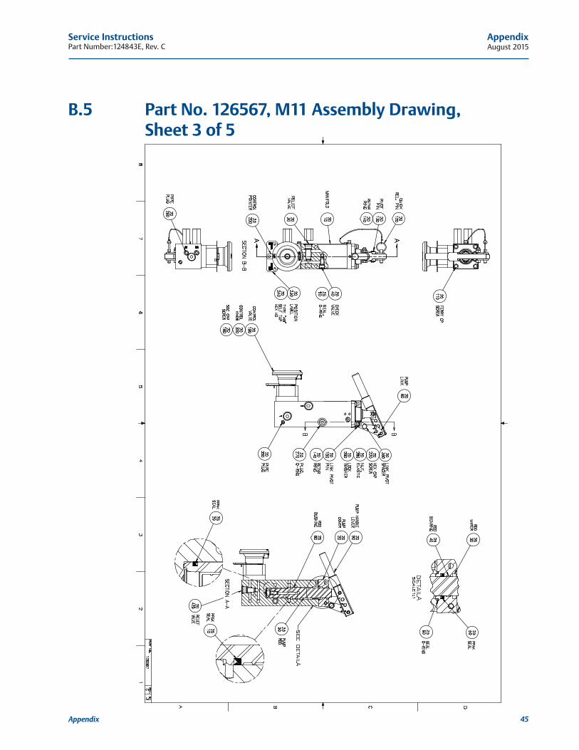
Service InstructionsPart Number:124843E, Rev. C August 2015
45
Appendix
Appendix
B.5 Part No. 126567, M11 Assembly Drawing, Sheet 3 of 5
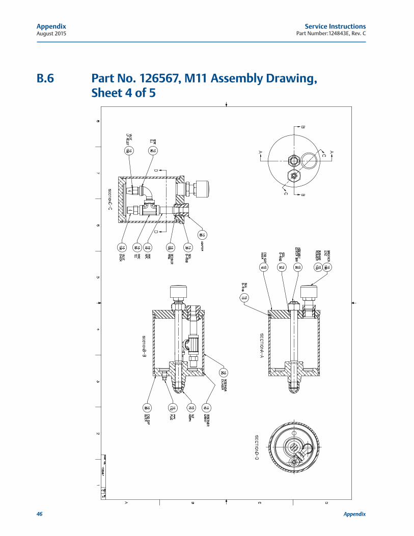
August 2015Service Instructions
Part Number:124843E, Rev. C
46
Appendix
Appendix
B.6 Part No. 126567, M11 Assembly Drawing, Sheet 4 of 5

Service InstructionsPart Number:124843E, Rev. C August 2015
47
Appendix
Appendix
B.7 Part No. 126567, M11 Assembly Drawing, Sheet 5 of 5

August 2015Service Instructions
Part Number:124843E, Rev. C
48
Appendix
Appendix
B.8 Part No. 121090, M11D-S Assembly Drawing, Sheet 1 of 3
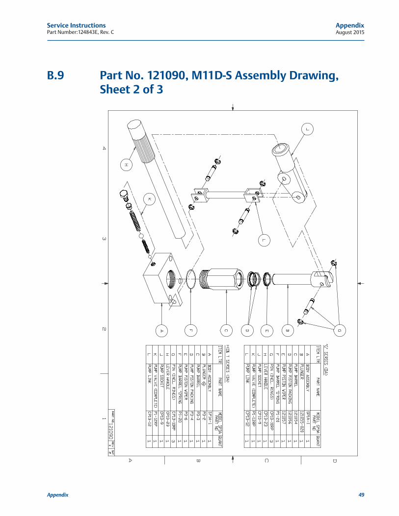
Service InstructionsPart Number:124843E, Rev. C August 2015
49
Appendix
Appendix
B.9 Part No. 121090, M11D-S Assembly Drawing, Sheet 2 of 3
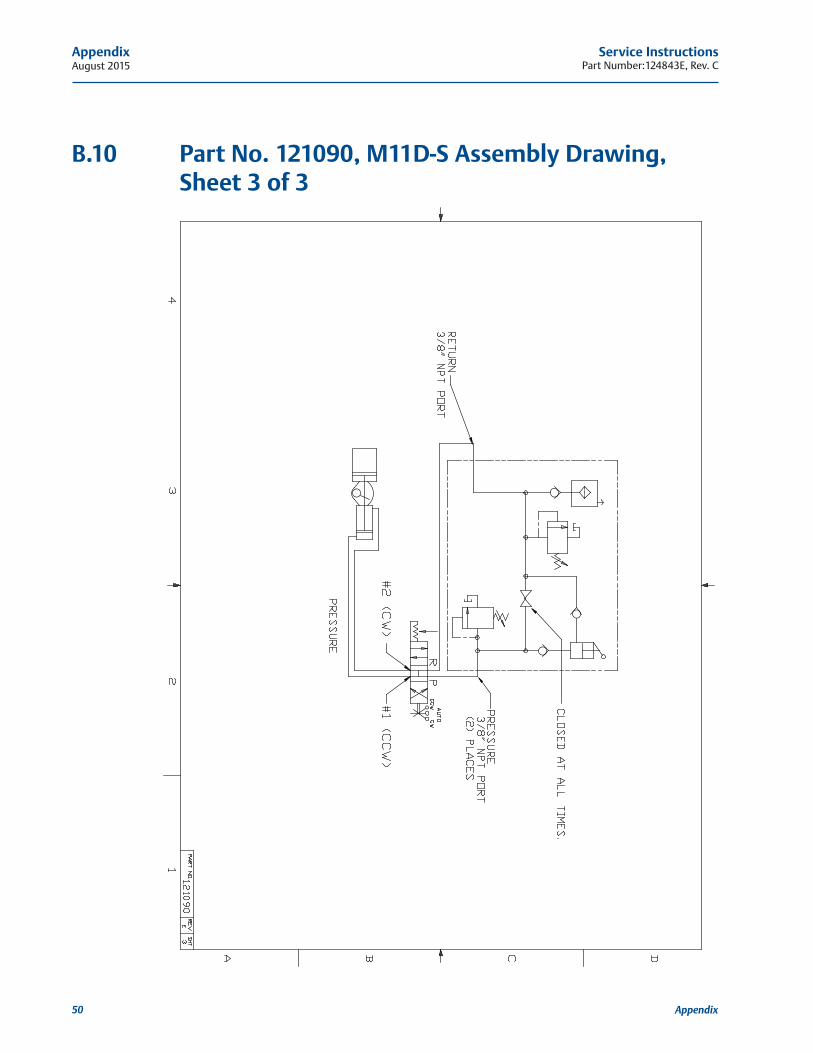
August 2015Service Instructions
Part Number:124843E, Rev. C
50
Appendix
Appendix
B.10 Part No. 121090, M11D-S Assembly Drawing, Sheet 3 of 3
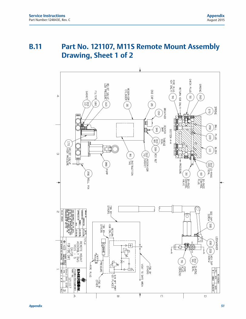
Service InstructionsPart Number:124843E, Rev. C August 2015
51
Appendix
Appendix
B.11 Part No. 121107, M11S Remote Mount Assembly Drawing, Sheet 1 of 2
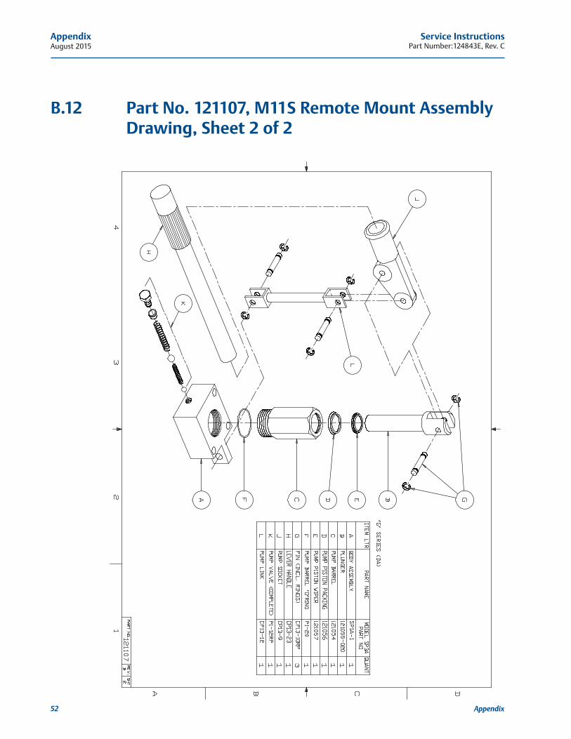
August 2015Service Instructions
Part Number:124843E, Rev. C
52
Appendix
Appendix
B.12 Part No. 121107, M11S Remote Mount Assembly Drawing, Sheet 2 of 2

World Area Configuration Centers (WACC) offer sales support, service, inventory and commissioning to our global customers. Choose the WACC or sales office nearest you:
www.emersonprocess.com/bettis
©2015 Emerson Process Management. All rights reserved. The Emerson logo is a trademark and service mark of Emerson Electric Co. Bettis is a mark of one of the Emerson Process Management family of companies. All other marks are property of their respective owners. The contents of this publication are presented for information purposes only, and while every effort has been made to ensure their accuracy, they are not to be construed as warranties or guarantees, express or implied, regarding the products or services described herein or their use or applicability. All sales are governed by our terms and conditions, which are available on request. We reserve the right to modify or improve the designs or specifications of our products at any time without notice.
NORTH & SOUTH AMERICA 19200 Northwest Freeway Houston, TX 77065 T +1 281 477 4100 F +1 281 477 2809Av. Hollingsworth, 325, Iporanga Sorocaba, SP 18087-105 Brazil T +55 15 3238 3788 F +55 15 3228 3300
ASIA PACIFIC No. 9 Gul Road #01-02 Singapore 629361 T +65 6501 4600 F +65 6268 0028 No.1 Lai Yuan Road Wuqing Development Area Tianjin 301700 P.R.China T +86 22 8212 3300 F +86 22 8212 3308
MIDDLE EAST & AFRICA P. O. Box 17033 Dubai United Arab Emirates T +971 4 811 8100 F +971 4 886 5465
P. O. Box 10305 Jubail 31961 Saudi Arabia T +966 3 340 8650 F +966 3 340 8790
24 Angus Crescent Longmeadow Business Estate East P.O. Box 6908; Greenstone 1616 Modderfontein, Extension 5 South AfricaT +27 11 451 3700F +27 11 451 3800
EUROPE Asveldweg 11 7556 BR Hengelo (O) The Netherlands T +31 74 256 1010 F +31 74 291 0938
For complete list of sales and manufacturing sites, please visit www.emersonprocess.com/valveautomationlocations Or contact us at [email protected]