g. sjoberg and n.-g. ingesten - tms · g. sjoberg and n.-g. ingesten volvo flygrnotor ab materials...
TRANSCRIPT
Grain Boundary S-phase Morphologies, Carbides and
Notch Rupture Sensitivity of Cast Alloy 718
G. Sjoberg and N.-G. Ingesten
Volvo Flygrnotor AB Materials Technology
Trollhattau, Sweden
R. G. Carlson
General Electric Company GE Aircraft Engines
Engineering Materials Technology Laboratories Cincinnati, Ohio
Abstract
Notch sensitivity has been connected with the presence of a film-like s-phase morphology in the grain boundaries of cast test bars of Alloy 718 of a problem material in which premature fracture occurred during testing of smooth stress rupture bars at 650 “C. A heat treatment designed to produce a plate-like S-phase morphology at the grain boundaries improved the material dramatically. Comparison with a reference material indicated the that the presence of coarse MC-carbides (0.9NbO.lTiC) at the grain boundaries attributed to the notch sensitivity problem. The degradation of the material by the carbides seems to be due to a considerable swelling action during a selective oxidation of these carbides. Additionally, a formation of a liquid phase at the carbides was confirmed. The volume increase of the selectively oxidized carbides was demonstrated by a an experiment in which two pieces of cast Alloy 718 with polish- ed surfaces facing one another were pressed together and exposed to air at 650 “C for one hour. Introduction
Stress rupture testing of smooth bars at 649 “C (l200 OF) at 621 MPa (90.000 Psi) for 20 hours is considered as a severe production test for Alloy 718 structural castings. For practical reasons such testing is performed on ‘cast to size’ bars rather than on specimens excised from the integral parts of the castings. The grain size of such ‘cast to size’ test bars is however finer than the grain size of most of the bulk material in a large structural casting and the testing of such bars is consequently of limited value. It is still valued as an indicator of proper process control.
Due to a change of the thermal conditions during the casting process of the very large compressor rear frame for the General Electric CF6-80C aircraft engine most of the test bars failed the twenty hours test. The structural material of the casting was however not degraded which was confiied by testing performed on excised material from all frames were the ‘cast to size’ bars did not meet the requirements.
Superalloys 718,625 and Various Derivatives Edited by Edward A. Lxia
The Minerals, Metals & Materials Society, 1991
603
Although the practical problem had been resolved there was an interest to understand why most of the ‘cast to size’ test bars failed and an investigation was initiated at General Electric (GE), Engineering Materials Technology Laboratory (EMTL) in Evendale, Cincinnati, Ohio.
In this investigation, however, no major differences could be found between failed and non- failed bars. Grain size and dendritic arm spacing were the same. The only difference found was the microhardness ratio between interdendritic and dendritic core regions. A small but consistently larger hardness ratio was found in the failed bars. The fracture surface revealed a very pronounced intergrannlar fracture which emphasized the importance of the grain boundaries. By closer examination a film-like S-phase was found in all boundaries close to the fracture surfaces. In the non-failed bars such delta fihns were much less frequent.
By consulting the extensive literature on Alloy 718 and similar alloys it is obvious that there are different problems and material mechanisms associated with this type of high temperature intergranular weakness. Main areas are notch sensitivity, crack growth and creep, inhomogeneous slip band deformation versus homogeneous deformation, ductility, environment, intergranular oxidation, chromium content, incipient melting of Laves phase and MC-carbides, microstructure and grain boundary morphology as well as heat treatment schedules. Most of the research has been performed on wrought material but the high temperature grain boundary weakness is a com- mon feature with cast material. In table I, listing research contributions, the above areas are given as subheadings.
The basic understanding has been elusive but recent research at GE has been fruitful due to the growing insight (1) (K.-M. Chang 1990). A recent review (2) (L. A. James 1989) covers the fatigue crack growth from many phenomenological points of view.
TableIResearchAreasReIatedtoHighTempemture blk7.pU4bW~tmdl-iStOf~
(3)MmriarMdJ~es1964,(4)EEiseLrteil~(5)Wa~pndHoll1%~(6)Rrcymond1%~(7)W~onI97~ (8)MulletrmdDonachie1975,(9)Menidr1974 (1O)XiietaL 1988
(7)Wfion lwy (ll)hh?ickl974, (12)Smith mulhfiil97~ (13)Fhwn 198Q (14)SadammdaandShohinian 1980, (1S)SandezxetaL 198z (l4)ClavelandPineau 1982, (17)PedmnrmdPineaul9~ (18)CGnetaL 1984d(19)1989,(2O)lkmbupjetd 1985and(21)19& (22)chrmgl985mrd(l)l~(23)Jraesrmd~~~1~(~)~ondImmm~nl~(25)KouletaL 1% [26)chfwwdil989
Slivbandvemrr homoRsreour&+onnationmeehmrinn~toaerificolsizeofthehmdeninav~ (~)PmJonisetoLl965),((28)cDzmmulpinemc1~(7)wilron1~(29)Ob~etaL 1974, (11)h4enick1974and(9)197~ (14)clavelandpinemr 1% (1S)SanderetaL 1981,(30)uaVeletd 1980 (21)ThambumjetaL 19% (31)Matrhionnietal. 1988, (26)&hatuwedil989
DUCtili& (4)Eiselstein 1%5, (32)iUrnyhandManim1%9,(7)~on 1973 (9)Mekkl976
EnvircMmentasakevfoctor (13)Fknwn 1984 (14)SadaIwh andShahi&n I& (l7)PednmandPheaul~ (20)llwmbumjetd 1985and(2l)ls!& (22) cYlaJlg1985,(33)AdieuetaL 1989
CYtmmiumwntent (22)chlmg19~ (39)IolwetaL 1989
604
(40) Kiwmvsky et aL 1989, (41) Thomron and Gena~lu 1983, (42) Cieskzk et al 1989, (43) Bouse 1989
cmbon andcarbides (3) Maniar and James 1%4, (4) Eirektein 1%5, (5) Wagtw and Hall 1%5, (44) Kinnan and Wwington 1970, (45) Sbvup and R@ese I%!$ (32) Muzyka and Mark IWS, (46) Bamasvamy et aL 1972, (11) Menick 1974, (12) Smith and Miilll97& (47) Jackman et aL 198Q (48) Lerch 1982 (17) Pe&vn and Pineau 19g2, (34) Ratchet andRemy 1932 and (35) 1983, (41) llwmson and Gencuiu 1983, (49) Moyer 1984, (21) Thmnbunaj et al. 1% (1) Chang 1990, (SO) Mius and Blackbum 19%
hBmsbudu?e and Smin boundarymomhokxy (4) Eisektebz 1965, (6) Raymond 1967, (51) Boesch and Cana& 1%9, (44) Kbman and WmrLtgron 1970. (9) Menick 1976 (52) Bouse and Schitke 1980, (14) Sakmmda and Shinian 1984 (18) Chen et aL 1984 and (19) 1989, (49) Moyer 1984, (20) Thambw@ et CrL 1985 and (21) 1986j (22) Gang 1985 and (1) 199Q (23) James and Mills 1985, (53) Zhang et aL 1987 (54) Bmoks and Bnk’gw 198& (24) Koul and lmmari&on 198& (25) Kind et aL 19865 (10) Xi et aL 1% (43) Bouse 19m, (55) Gmkon and Radavkb 1989, (42) CTeskak et a.? 1989, (56) Gou et al. 1989, (39) Joner et aL 19es. (40) fiorovsky et aL 1989, (57) Kmuger 1989, (SO) Milt3 and Bkkbwn 19%
Effectdf%heat-- andsohtibntemrxmtun3 (4) Eisektein l%S, (5) Wagxer and Hall 1%5, (7) Wilson 1974 (8) Muller and Donachie 1975, (9) Menick 1976 (12) Smith and Miill197& (14) Sadammdk and Shahinian 1984 (20) lkmbumj et al 1985 and (21) 19% (22) Chang 1985 and (I) lm, (24) Koul and Jmmarigeon 1% (50) Mii lmnd Bkxkhum 1989s
There seems to be two opposing views on the effect 01 S-phase on the mechanical properties. The frost and for a long time prevailing view (6,10,23,44,50.51,57) is that the S-phase degrades the mechanical properties, especiahy the low temperature fracture toughness and the low cycle fatigue properties. The main reason for this degradation is that the S-phase is niobium-rich (Ni3Cb) and the surrounding matrix will consequently be depleted on this element during the precipitation. Since the main hardening precipitate, the Y”, is of the same chemical composition as the Sphase it will later during the age hn*dening be difficult to get proper hardening close to th:, S-precipitates, a zone denuded in 7” will develop (6,44). Accordingly, this zone will be weak. The second view is that the presence of the S-phase at the grain boundaries is good for the high temperature stress rupture and crack growth properties (9, 10, 14, 18, 20, 21,24,25, 53, 54, 57). This latter view seems at fust glance to be in conflict with the first view as well as with our observations.
The S-phase generally precipitates along specific habitus (5) in the matrix by which a plate- lie morphology is produced. S-phase of film-like morphology is often reported as ‘grain boundary 6’ (54) which makes sense since it consists of individual particles though very closely spaced which is revealed at higher magnification. Such ‘films’ precipitates in the tower part of the temperature region where S-phase precipitates. At a higher temperature, the S -phase grain boundary nucleuses grow along the favorable habitus into the surrounding grain matrixes by which the film-like morphology gradually disappears. In cast alloys such nucleation and growth at grain boundaries is enhanced by high niobium concentrations (55).
If the depletion of the niobium close to the d-phase and the consequent weakness in this zone is taken into consideration any S’film’ morphology will provide for an easy crack path while a morphology with S-phase plates extending into the surrouuding grains will produce a tortuous path. As a consequence the latter type of morphology should improve the mechanical properties of the material and this point of view was to be the working hypothesis for the further investigations performed at Volvo Flygmotor AB in Sweden.
605
Experimental
The effect of two grain boundary S-phase morphologies, one t&u-like and the other plate-like, on high temperature mechanical properties were to be tested. Notched stress rupture testing was chosen since the literature indicated this type of testing to be sensitive to high temperature grain boundary weakness (7).
‘Cast to size’ stress rupture bars were used. The length and diameter of the cast gage section was 32 mm and 7 mm, respectively. By machining, the diameter was reduced to 5.75 mm and a notch with a tip radius of 0.15 mm was carefully ground at the center of the bar. The notch angle was 60 degrees. The diameter under the notch was 4.05 mm with an accordingly reduced cross section of 50 %.
Two sets of bars were used in our investigations. The fast set consists of 6 bars which will be referred to as ‘problem bars’ since they were cut from the periphery of two castings (three from each) for which the thermal conditions were changed which caused the stress rupture problem as mentioned in the introduction. The material will be referred to as ‘problem material’. On each of these two castings there were four bars one of which was tested as part of the production acceptance testing procedure but which failed within the 20 hours limit and often within a few hours. From the statistical process control (SPC) records it was evident that the probability of failure in each of the remaining three bars could be estimated to 50 %. Also, by the SPC records it was clear that there was no correlation between stress rupture failure of the cast to size bars and the room temperature tensile properties of excised material or the chemistries. Neither could any correlation be found with the HIP procedure used. (For instance, there was a suspicion that the position of the large castings in the HIP vessel could be coupled with the failed bars since the cooling down rate in the vessels is not controlled and the fact that the cooling down rate varies considerably depending on the position in the vessel.) The second group of test material consists of bars from four similar castings but cast under standard thermal conditions. The bars in this group were not HIP treated and these bars will be referred to as ‘reference bars’ and the material to as ‘reference material’. In table II the chemical composition of each bar is shown as determined per master heat lot. Following a homogenization at 1090 “C! for one hour for both types of bars, the HIP treatment adds 4 hours homogenization at 1120 “C to the problem bars.
To be able to produce on the one hand a film-like grain boundary and on the other a plate-like serrate S-phase a heat treatment schedule had to be designed. Before precipitation of the S-phase a solution heat treatment at high temperature was thought necessary to ensure that all previous S-phase had been dissolved. 1100 “C and 0.5 hr were chosen to limit the influence on the homogenization pattern in the as received material. Common metallurgical sense and encouragement from literature (9,54) made us choose a low temperature after the solutioning heat treatment to nucleate the 6 -phase at grain boundaries both for the fihn and the plate-like S-phase. For the plate-like S-phase a higher temperature was chosen in a subsequent step to allow the S-phase nucleuses to grow into the surrounding matrix.
A probable precursor to the S-phase at the low temperature heat treatment step is the 7” (27, 29) which will nucleate throughout the microstructure and transform into the S-phase either directly at the lower heat treatment temperatures or later at the second, high temperature, step. At the high temperature all 7” can be dissolved without compromising the design of the S-phase morphology. Since the high temperature treatment step will be a proper solutioning it can be directly followed by conventional ageing.
606
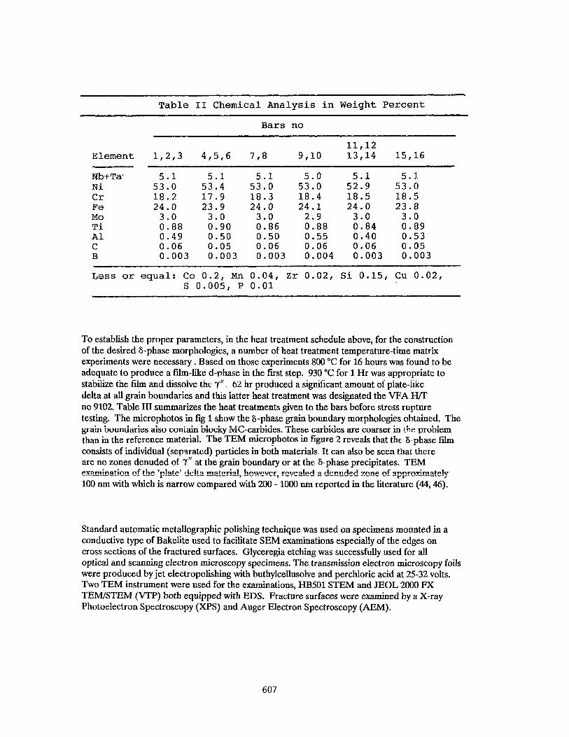
Table II Chemical Analysis in Weight Percent
Element
Bars no
11,12 1,2,3 4,5,6 7,8 9,lO 13,14 15,16
Nb+Ta- 5.1 5.1 5.1 5.0 5.1 5.1 Ni 53.0 53.4 53.0 53.0 52.9 53.0 Cr 18.2 17.9 18.3 18.4 18.5 18.5 Fe 24.0 23.9 24.0 24.1 24.0 23.8 MO 3.0 3.0 3.0 2.9 3.0 3.0 Ti 0.88 0.90 0.86 0.88 0.84 0.89 Al 0.49 0.50 0.50 0.55 0.40 0.53 C 0.06 0.05 0.06 0.06 0.06 0.05 B 0.003 0.003 0.003 0.004 0.003 0.003
Less or equal: Co 0.2, Mn 0.04, Zr 0.02, Si 0.15, Cu 0.02, s 0.005, P 0.01
To establish the proper parameters, in the heat treatment schedule above, for the construction of the desired S-phase morphologies, a number of heat treatment temperature-time matrix experiments were necessary. Based on those experiments 800 “C for 16 hours was found to be adequate to produce a film-like d-phase in the first step. 930 “C for 1 Hr was appropriate to stabilize the film and dissolve the 7”. 62 hr produced a significant amount of plate-like delta at all grain boundaries and this latter heat treatment was designated the VFA H/T no 9102. Table III summarizes the heat treatments given to the bars before stress rupture testing. The microphotos in fig 1 show the b-phase grain boundary morphologies obtained. The grain boundaries also contain blocky MC-carbides. These carbides are coarser in the problem than in the reference material. The TEM microphotos in figure 2 reveals that the S-phase film consists of individual (separated) particles in both materials, It can also be seen that there are no zones denuded of TN at the grain boundary or at the &phase precipitates. TEM examination of the ‘plate’ delta material, however, revealed a denuded zone of approximately 100 nm with which is narrow compared with 200 - 1000 mn reported in the literature (44,46).
Standard automatic metallographic polishing technique was used on specimens mounted in a conductive type of Bakelite used to facilitate SEM examinations especially of the edges on cross sections of the fractured surfaces. Glyceregia etching was successfully used for all optical and scanning electron microscopy specimens. The transmission electron microscopy foils were produced by jet electropolishmg with buthylcellusolve and perchloric acid at 25-32 volts. Two TEM instrument were used for the examinations, HB501 STEM and JEOL 2000 FX TEM/STEM (VTP) both equipped with EDS. Fracture surfaces were examined by a X-ray Photoelectron Spectroscopy (XPS) and Auger Electron Spectroscopy (AEM).
607

Table III
Purpose of heat treat- ment step
Grain Boundary 6 morphology
VPA H/T No 9102 Film-like Plate-like
Solution of 6
llOO'c, 0.5 Hr Air cool to
room temp Same
Precipitation of 'film' at grain boundary
EOO'C, 16 Hr Air cool to
room temp Same
Solution of overaged 7" stabilize 6 morphology
930 'C, 1 Hr 93OT, 62 Hr Air cool to Air cool to
room Temp room temp
First age 76O"C, 5 Hr Cool faster
than 1 C/min
Same
Second age 649"C, 1 Hr Same
Figure l-F&n-like and plate-like E-phase atgrainboundaries ofthe problemmaterial(la andlc) and the reference material(lb andld).
608

Figure 2 - TEM-rnicrophotgraphs of high angle grain boundaries with S-phase precipitates in problem material (2 a) and reference material (2 b).
Results
The results from the mechanical testing are shown in table IV. The HVS hardness measurements were made on polished cross sections of the stress rupture tested bars approximately 5 mm from the notch in the center of the bars. In the cross sections of most of the reference bars local areas with shrinkage porosity could be found. No porosity was seen in the HIP treated problem bars. During hardness testing a few of the hardness indentations were positioned in such areas and was then discarded and new measurements were made. The hardness values reported for the reference material thus reflects the matrix hardness rather than the average hardness for the reference material.
However, checking with HRC at the end of the tested bars as welI as with HV20 on the polished sections did not reveal any significant pattern that would make us doubt that the HVS hardness numbers reported, as the average of three measurements, also are fair estimates of the average hardness. Of more importance is probably the general low level in the plate-like S-phase reference material. Checking with HRC gave the following mean numbers for bars 12 thru 16 respectively - 36,36,32,36 and 37. The reason for why the reference material responds differently than the problem material with these comparatively low hardness number is not clear to us. A possible explanation could be that the grain size is smaller and the b-plates penetrates through the grains while, due to the coarser grains, this does not occur in the problem material as can be seen in figure 1.
The stress rupture testing was performed by stepwise increasing the load every 24 hours except at the highest stress level of 896 MPa. The poor properties of the problem material with film- like b-phase seems to confirm our hypothesis of a deleterious influence of such a film very convincingly. The results from the testing of the reference material is however not equally convincing. Nevertheless, the good properties of the plate-like grain boundary S-phase for both problem and reference material supports our hypothesis about the beneficial influence of this type of grain boundary &phase morphology very strongly.
609
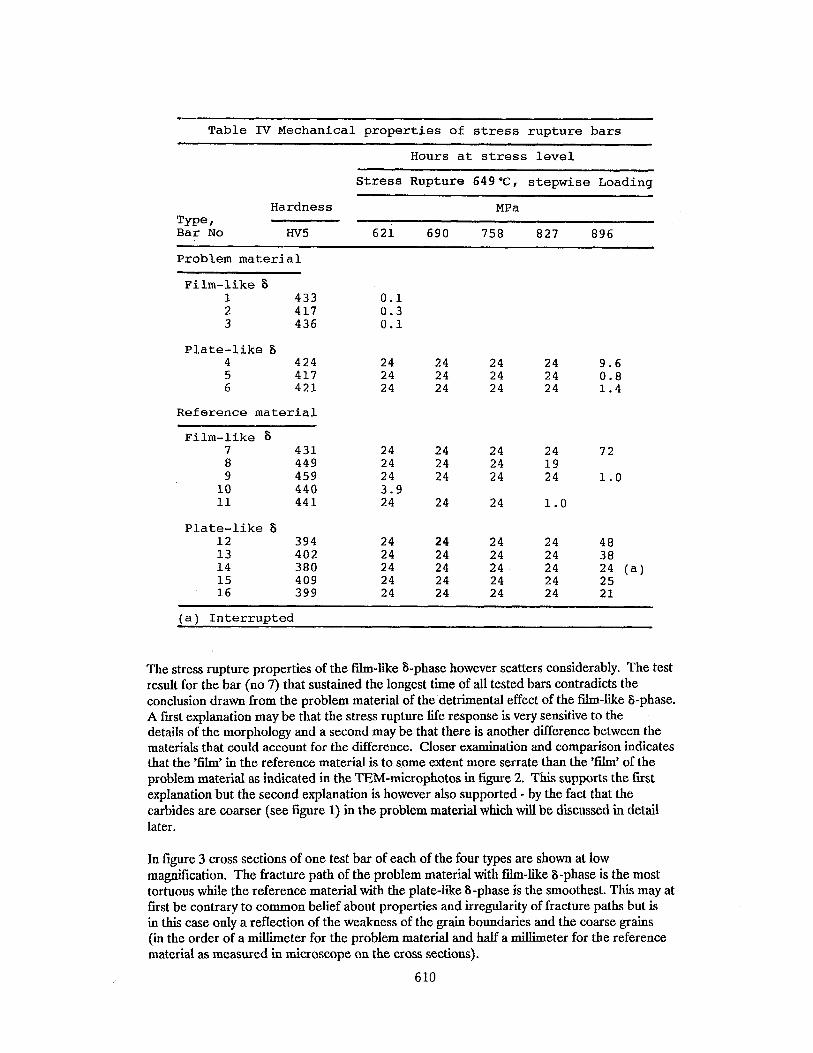
Table IV Mechanical properties of stress rupture bars
Hours at stress level
Stress Rupture 649'C, stepwise Loading
Tw=, Bar No
Hardness MPa
Hv5 621 690 758 827 896
Problem material
Film-like 6 1 433
417 436
Plate-like S 4 424 5 417 6 421
Reference material
Film-like 6 7 431 8 449 9 459
10 440 11 441
Plate-like S 12 394 13 402 14 380 15 409 16 399
0.1 0.3 0.1
24 24 24 24 9.6 24 24 24 24 0.8 24 24 24 24 1.4
24 24 24 3.9 24
24 24 24 24 48 24 24 24 24 38 24 24 24 24 24 (4 24 24 24 24 25 24 24 24 24 21
24 24 24 24 24 19 24 24 24
24 24 1.0
72
1.0
(a) Interrupted
The stress rupture properties of the film-like b-phasehowever scatters considerably. The test result for the bar (no 7) that sustained the longest time of all tested bars contradicts the conclusion drawn from the problem material of the detrimental effect of the film-like S-phase. A fust explanation may be that the stress rupture life response is very sensitive to the details of the morphology and a second may be that there is another difference between the materials that could account for the difference. Closer examination and comparison indicates that the ‘film’ in the reference material is to some extent more serrate than the ‘film’ of the problem material as indicated in the TEM-microphotos in figure 2. This supports the first explanation but the second explanation is however also supported - by the fact that the carbides are coarser (see figure 1) in the problem material which will be discussed in detail later.
In figure 3 cross sections of one test bar of each of the four types are shown at low magnification. The fracture path of the problem material with film-like S-phase is the most tortuous while the reference material with the plate-like S-phase is the smoothest. This may at first be contrary to common belief about properties and irregularity of fracture paths but is in this case only a reflection of the weakness of the grain boundaries and the coarse grains (in the order of a millimeter for the problem material and half a millimeter for the reference material as measured in microscope on the cross sections).
610

Figure 3. Cross sections at fracture surface of stress-rupture bars. 3 a - problem material and 3 b -reference material with film-lie S-phase. 3 c and 3 6 - problem material and reference material with plate-like grain boundary S-phase.
One very important acoustic observation was made during the rupture testing. Immediately before (a fraction of a second) the final fracture there was a setting movement in the stress rupture machines which made a warning sound.
Observation on the fracture surfaces revealed that the fraction of intergranular fracture covered roughly one third of the surface of all tested bars (a wedge shape which followed the columnar grains towards the center) while the two other thirds were covered by transgranular fracture. This was at first confusing in the light of the large span of stresses and rupture times involved. This can nevertheless make sense if the acoustic observation and some observations as reported in the literature on crack growth, stress intensities and fracture modes are considered (14,23). Intergrauular fracture is generally found at low or intermediate stress intensities. At very high stress intensities this fracture mode shifts to the transgranular and , the growth rate is reduced considerably (14) which is an anomalous in comparison with an all transgranular fracture mode.
The conclusion to be drawn from our testing is consequently that the initiation of a crack is life-critical, that there is a crack growth which is very rapid (allowing for the acoustic emission) and that the rate of the final fracture is slightly lower due to the shift from intergranular to transgranular fracture mode at high stress intensities. This conclusion is further supported the color observations made on the fractured surfaces.
The intergranular fraction of the surface was clear and deep blue on bars (no 5,6,7,8,9, 12,15 and 16) which were removed from the hot furnace after a few minutes. The color of the other bars which were removed after longer periods of time had been replaced by a glittery and colorless appearance. The conclusion is that the intergranular part of the fracture surface could not have been fully exposed to the surrounding atmosphere during the testing or otherwise it would never have appeared clear blue. On closer examination of the intergranular part of the fracture surfaces on those bars which had been removed from the furnace within a short period of time it was found that a fraction of these blue surfaces also appeared glittery which suggests that this fraction of the intergranular part of the fracture surface had been exposed to the atmosphere for extended periods of time. For instance in bar no 8 (&‘film in reference
611
material) a glittery 20 degree wedge was found to extend from the notch approximately one mm towards the center as a part of the large 100 degree blue wedge outlining the intergranular fraction of the fracture surface. It is believed that this small inserted wedge reflects the ultimate size of the initiation crack when it had gradually grown to the critical size. This is also supported by the fact that the glittery appearance is gradually reduced from the center towards the border of this small wedge which indicates full exposure to air for varying periods ‘of time.
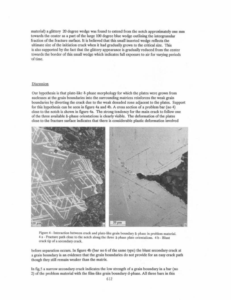
Our hypothesis is that plate-like a-phase morphology for which the plates were grown from nucleuses at the grain boundaries into the surrounding matrices reinforces the weak grain boundaries by diverting the crack due to the weak denuded zone adjacent to the plates. Support for this hypothesis can be seen in figure 4a and 4b. A cross section of a problem bar (no 4) close to the notch is shown in figure 4a. The strong tendency for the main crack to follow one of the three available &phase orientations is clearly visible. The deformation of the plates close to the fracture surface indicates that there is considerable plastic deformation involved
d
: r rl”
1 /
r c*
#
: *
; * ****
1
I_
Figure 4 - Interaction between crack and plate-like grain boundary &phase in problem material. 4 a - Fracture path close to the notch along the three &phase plate orientations. 4 b - Blunt crack tip of a secondary crack.
before separation occurs. In figure 4b (bar no 6 of the same type) the blunt secondary crack at a grain boundary is an evidence that the grain boundaries do not provide for an easy crack path though they still remain weaker than the matrix.
In fig5 a narrow secondary crack indicates the low strength of a grain boundary in a bar (no 2) of the problem material with the fihn-like grain boundary d-phase. All three bars in this
612
group contained this type of very narrow secondary cracks. As seen in fig 3 such cracks can be very deep, in the order a grain diameter.
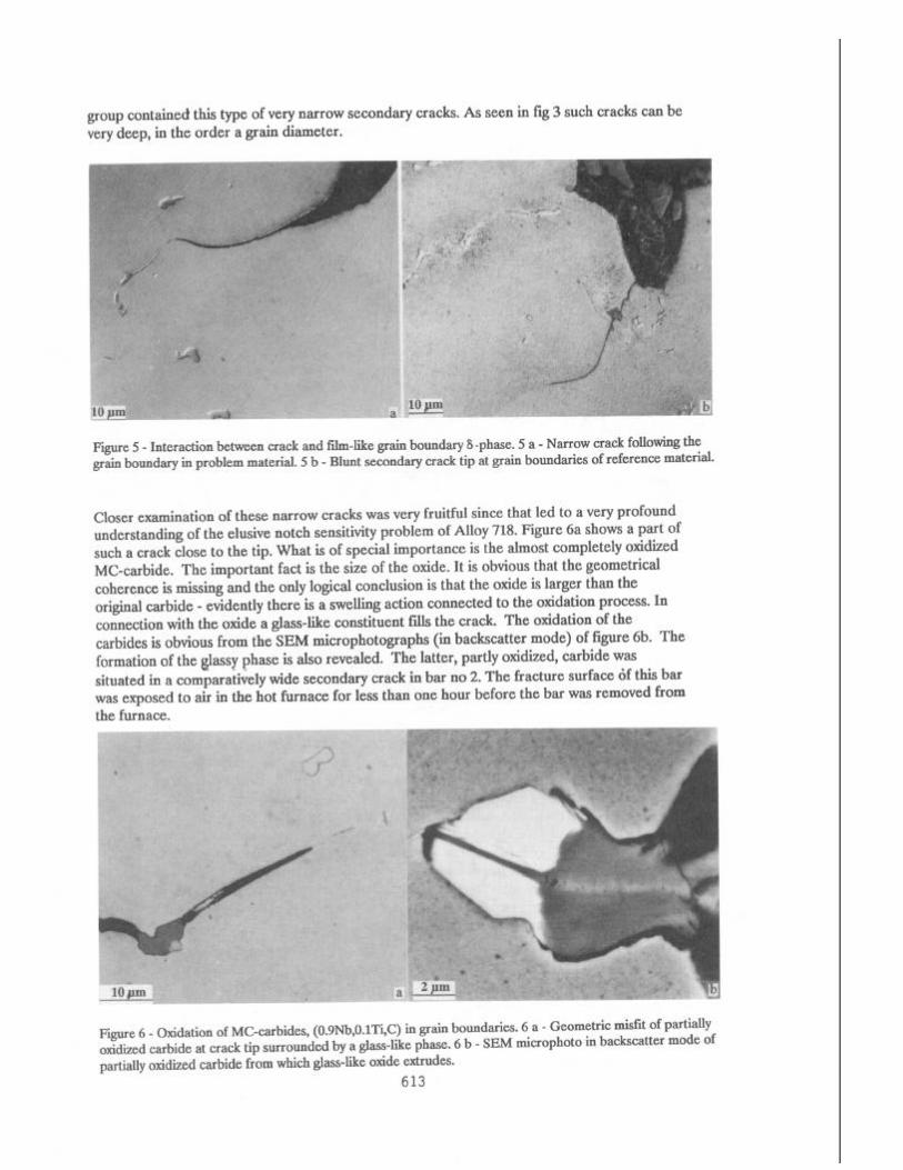
Figure 5 - Interaction between crack and film-like grain boundary 6 -phase. 5 a - Narrow crack following tht grain boundary in problem material. 5 b - Blunt secondary crack tip at grain boundaries of reference materml.
Closer examination of these narrow cracks was very fruitful since that led to a very profound understanding of the elusive notch sensitivity problem of Alloy 718. Figure 6a shows a part of such a crack close to the tip. What is of special importance is the almost completely oxidized MC-carbide. The important fact is the size of the oxide. It is obvious that the geometrical coherence is missing and the only logical conclusion is that the oxide is larger than the original carbide - evidently there is a swelling action connected to the oxidation process. In connection with the oxide a glass-like constituent fills the crack. The oxidation of the carbides is obvious from the SEM microphotographs (m backscatter mode) of figure 6b. The formation of the glassy phase is also revealed. The latter, partly oxidized, carbide was situated in a comparatively wide secondary crack in bar no 2. The fracture surface of this bar was exposed to air in the hot furnace for less than one hour before the bar was removed from the furnace.
#“” I _ jj_ * ~- _ I *
Figure 6 - Oxidation of MC-carbides, (0.9Nb,O.lTi,C) in grain boundaries. 6 a - Geometric misfit of partially oxidized carbide at crack tip surrounded by a glass-like phase. 6 b - SEM microphoto in backscatter mode of partially oxidized carbide from which glass-like oxide extrudes.
613
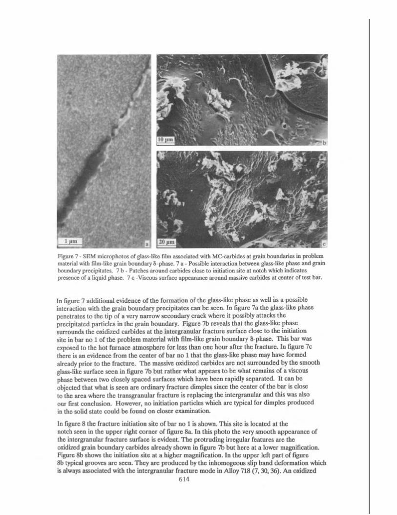
Figure 7 - SEM microphotos of glass-like film associated with MC-carbides at grain boundaries in problem material with fb-like gram boundary 6 -phase. 7 a - Possible interaction between glass-like phase and grain boundary precipitates. 7 b - Patches around carbides close to initiation site at notch which indicates presence of a liquid phase. 7 c -Viscous surface appearance around massive carbides at center of test bar.
In figure 7 additional evidence of the formation of the glass-like phase as well as a possible interaction with the grain boundary precipitates can be seen. In figure 7a the glass-like phase penetrates to the tip of a very narrow secondary crack where it possibly attacks the precipitated particles in the grain boundary. Figure 7b reveals that the glass-like phase surrounds the oxidized carbides at the intergranular fracture surface close to the initiation site in bar no 1 of the problem material with film-like grain boundary b-phase. This bar was exposed to the hot furnace atmosphere for less than one hour after the fracture. In figure 7c there is an evidence from the center of bar no 1 that the glass-like phase may have formed already prior to the fracture. The massive oxidized carbides are not surrounded by the smooth glass-like surface seen in figure 7b but rather what appears to be what remains of a viscous phase between two closely spaced surfaces which have been rapidly separated. It can be objected that what is seen are ordinary fracture dimples since the center of the bar is close to the area where the transgranular fracture is replacing the intergranular and this was also our first conclusion. However, no initiation particles which are typical for dimples produced in the solid state could be found on closer examination.
In figure 8 the fracture initiation site of bar no 1 is shown. This site is located at the notch seen in the upper right comer of figure 8a. In this photo the very smooth appearance of the intergranular fracture surface is evident. The protruding &g&r featunz we the oxidized grain boundary carbides already shown in figure 7b but here at a lower magnification. Figure 8b shows the initiation site at a higher magnification. In the upper left part of figure gb typical grooves are seen. They are produced by the inhomogeous slip band deformation which is always associated with the intergramtlar fracture mode in Alloy 718 (7,30,36). An oxidized
614
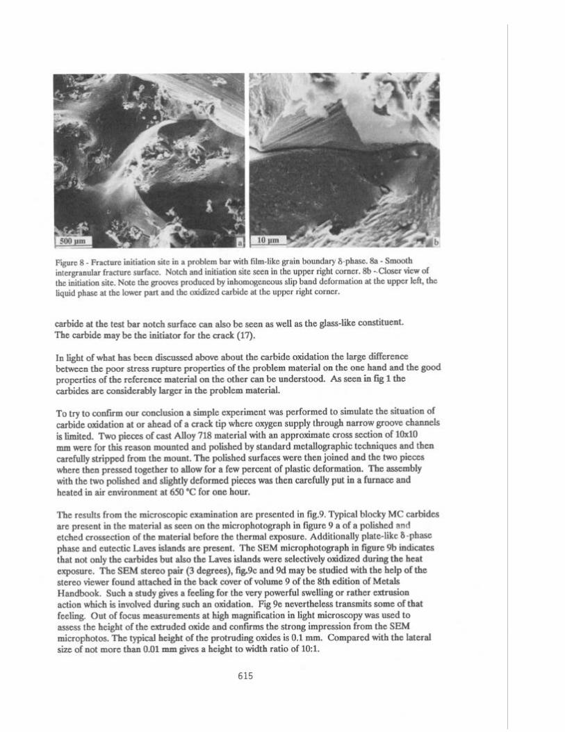
Figure 8 - Fracture initiation site in a problem bar with film-like grain boundary S-phase. 8a - Smooth intergranular fracture surface. Notch and initiation site seen in the upper right corner. 8b -.Closer view of the initiation site. Note the grooves produced by inhomogeneous slip band deformation at the upper left, the liquid phase at the lower part and the oxidized carbide at the upper right corner.
carbide at the test bar notch surface can also be seen as well as the glass-like constituent. The carbide may be the initiator for the crack (17).
In light of what has been discussed above about the carbide oxidation the large difference between the poor stress rupture properties of the problem material on the one hand and the good properties of the reference material on the other can be understood. As seen in fig 1 the carbides are considerably larger in the problem material.
To try to confirm our conclusion a simple experiment was performed to simulate the situation of carbide oxidation at or ahead of a crack tip where oxygen supply through narrow groove channels is limited. Two pieces of cast Alloy 718 material with an approximate cross section of 10x10 mm were for this reason mounted and polished by standard metallographic techniques and then carefully stripped from the mount. The polished surfaces were then joined and the two pieces where then pressed together to allow for a few percent of plastic deformation. The assembly with the two polished and slightly deformed pieces was then carefully put in a furnace and heated in air environment at 650 ‘C for one hour.
The results from the microscopic examination are presented in tig.9. Typical blocky MC carbides are present in the material as seen on the microphotograph in figure 9 a of a polished and etched crossection of the material before the thermal exposure. Additionally plate-like 6 -phase phase and eutectic Laves islands are present. The SEM microphotograph in figure 9b indicates that not only the carbides but also the Laves islands were selectively oxidized during the heat exposure. The SEM stereo pair (3 degrees), fig.9c and 9d may be studied with the help of the stereo viewer found attached in the back cover of volume 9 of the 8th edition of Metals Handbook. Such a study gives a feeling for the very powerful swelling or rather extrusion action which is involved during such an oxidation. Fig 9e nevertheless transmits some of that feeling. Out of focus measurements at high magnification in light microscopy was used to assess the height of the extruded oxide and confvms the strong impression from the SEM microphotos. The typical height of the protruding oxides is 0.1 mm. Compared with the lateral size of not more than 0.01 mm gives a height to width ratio of l&l.
615

Figure 9 - Microphotograph proofs of the swelling action at 650 “C during the 1 hour selective oxidation of gram boundary carbides and Laves-phase in experiment with two joined polished surfaces. 9 a - The m&o- structure of the cast Alloy 718 material used for the experiment. Blocky MC-carbides, Laves-phase and plate- like &phase are seen. 9 b - The oxidized phases protruding from the surface after the thermal exposure. 9 c and 9 d SEM stereo pair (3 degrees) reflecting the extrusion action involved during the selective oxidation (may be studied by stereo viewer attached to back cover of vol. 9 of eight edition of Metals Handbook). 9 e -Details of oxidized carbide morphology.
616
Conclusions -----------
1. Local plastic deformation takes place in front of a notch or crack.
2. By the inhomogeneous plastic slip band deformation grooves are produced at grain boundaries.
3. The grooves provides channels for limited transport of oxygen into the grain boundaries ahead of a notch or crack.
4. Grain boundary MC-carbides and Laves-phase will oxidize selectively.
5. The volume of the carbides increases considerably at the transformation to oxides.
6. The volume increase will provide powerful local stress risers in front of or at a crack tip.
7. A glass-like phase formed during the oxidation of the carbides may assist in penetration of grain boundaries.
8. Plate-like S-phase protruding from grain boundaries into surrounding grain matrices is effective in diverting initiation cracks from weak grain boundaries.
Acknowledgments
The initial support, from Steve Irvine at PCC, to add interrogative work to the production problem is here gratefully acknowledged. The SEM examinations and identification of grain boundary S-phase at GE by Stanley T. Wlodek was valuable for the progress of the work. The examinations by TEM, and XPS as well as the discussions with Goran Wirmark, Volvo, Technical Development, were necessary for the rapidly growing understanding of the fundamental mechanisms. The self-reliant SEM work of Sten Ljungkvist at VFA made contributions to the understanding of the fracture surface appearance. Finally but not least is the accurate work and observations of Fredrik Lindstrom, responsible for the stress rupture testing, acknowledged.
References
1. K.-M. Chang, M. F. Henry and M. G. Benz, Metallurgical Control of Fatigue Crack Propagation in Superalloy?, Journal of Materials, 12, (1990), 29-35.
2. L. A. James, “Fatigue Crack Propagation in Alloy 718: A Review”, SuperaIIov 718, MetaIhnxv & Applications, ed. E. A. Loria, TMS 1989,499-515.
3. G. N. Maniar and H. M. James, “Notch Sensitivity in A-286”, Technical Notes: Transactions of& ASM, 57 (1964), 369-370.
4. H. L. Eiselstein, “MetaIIurgy of a Columbium-Hardened Nickel-Chromium-Iron Alloy”, Advances && technology of Stainless Steels, ASTM-STP 369 (1965), 62-79. --
5. H. J. Wagner and A. M. HaU, “Physical Metallurgy of Alloy 718” (DMIC report 217, Defense Metals Information Center, (1965).
617
6. E. L. Raymond, “Effect on Grain Boundary Denudation of 7 ‘on Notch-Rupture Ductility of Inconel Nickel-Chromium Alloys X-750 and 718”, Transactions of& Metaihtrgical Societv of AIME , 239 (1967), 1415-1422.
7. D. J. Wilson, “Relationship of Mechanical Characteristics and Microstructural Features for the Time- Dependent Edge-Notch Sensitivity of Inconel718 Sheet”, Transactions off ASME, Journal of Engineering Materials 4 Technologv 1973, no. 4112-123.
8. J. A. MuUer and M. .I. Donachie, “The Effect of Solutions and Intermediate Heat Treatments on the Notch- Rupture Behavior of Inconel718”, Metallurgical Transactions, 6A (1975), 2221-2227.
9. H. F. Merrick, “Effect of Heat Treatment on the Structure and Properties of Extruded P/M Ahoy 718”, MetaIhrrgicaI Transaction, 7A (1976), 505-514.
10. X. Xie, Z. Xu, B. Qu, G. Chen and J. F. Radavich, “The Role of Mg on Structures and Mechanical Properties in Ahoy 718”, Sunerahovs 1988, eds. D. N. D&I et al., The Metallurgical society, 1988,635-642.
11. H. F. Merrick, “The Low Cycle Fatigue of Three Wrought Nickel-Base Ahoys”, Metallurgical Transactions, 5 (1974), 891-897.
12. H. H. Smith and D. J. Michel, “Fatigue Crack Propagation and Deformation Mode in Ahoy 718 at Elevated Temperatures”, (Report MPC-8, Metal Properties Council, 1978), 225-246.
13. S. FIoreen, “High Temperature Crack Growth Structure-Property Relationships in Nickel Base Superalloys”, Creep-Fatigue-Environment Interactions, eds R.M. PelIoux and N. S. Stohoff, TMS-AIME, 1980,112-127.
14. K. Sadananda and P. Shahinian, ‘Crack Growth Under Creep and Fatigue Conditions”, Creep-Fatipue- Environment Interactions, eds R.M. Pelloux and N. S. Stohoff, TMS-AIME, 1980,86-111.
15. T. H. Sanders, R. E. Frischmuth and G. T. Embley, “Temperature Dependent Deformation Mechanisms of Ahoy 718 in Low Cycle Fatigue”, MetaUurgicaI Transactions A- 12A (1981), 1003-1010.
16. M. Clavel and A. Pineau, “Fatigue Behavior of Two Nickel-base AUoys. I: Experimental Results on Low Cycle Fatigue, Fatigue Crack Propagation and Substructures” Material Science and 9--- Engineering, 55 (1982), 157-171.
17. J. P. Pedron and A. Pineau, “The Effect of Microstructure and Environment on the Crack Growth Behavior of Inconel718 Ahoy at 650 “C under Fatigue, Creep and Combined Loading”, Material Science and Engineering, 56 (1982), 143-156.
18. Guoiian Chen, Di Wang, Zhichao Xu, Jie Fu, Kequan Ni and Xishan Xie, “The Role of Smah Amounts of Magnesium in Nickel-Base and Iron-Nickel-Base Superalloys After High Temperature Exposures”, Proceedings of Superahovs 1984, eds. M. GeII et al., AIME, 1984,611-620.
19 G. Chen, Q. Zhu, D. Wang, X. Xie and J. F. Radavich, “Effects of Magnesium on Niobium Segregation and Impact Toughness in Cast Ahoy 718”, Superahov 718, Metallurgy& Anphcations, ed. E. A. Loria, TMS 1989,545-551.
20. R. Thamburaj, A. K. Koui, W. Wallace, T. Terada and M. C. de MaIherbe, “The Influence of Microstructure upon the Creep and Fatigue Crack Growth Behavior in INCONEL 718”, Time-Dependent Fracture, ed. A. S. Krausz, Martinus Nijhoff Publ., 1985,245260.
21. R. Thamburaj, T. Terada, A. K. KouI, W. Wallace and M. C. de MaIherbe, “The Influence of Microstructure and Environment upon Elevated Temperature Crack Growth Rates in Inconel718”, proC. Int Conf on Creeu, JSME/ASME, Tokyo, Japan 1986,275~283.
22. K.-M. Chang, “Time-Dependant Fatigue Crack Propagation in InconeI718 Superahoys”, Mechanical Behavior of Materials-V, eds M. C. Yan et al., Pergamon Press, New York, 1985,1l39-1147. --
618
23. L. A. James and W. J. Mills, “Effect of Heat-treatment and Heat-to-heat Variations in the Fatigue-crack Growth Response of Ahoy 718”, Engineering Fracture Mechanics, 22 (1985), 797-817
24. A. K. KouI and J.-P. Immarigeon, “Effect of Microstructure on Fatigue Crack Growth Rate”, Sunerahov 1988, eds. D. N. Duhl et al., The Metallurgical society, 1988, addendum 697-712.
25. A. K. Koul, P. Au, N. Behinger, R. Thamburaj, W. Wallace and J-P. Immarigeon, “Development of a Damage Tolerant Microstructure for Inconel718 Turbine Disk Material”, Superahov 1988, eds. D. N. DuhI et al., The MetaIIurgicaI Society, 1988,3-12.
26. M. C. Chaturvedi and Yafang Han, “Creep Deformation of Ahoy 718”, Superahov 718, MetaIhrrm& Applications, ed. E. A. Loria, TMS 1989,489-498.
27. D. F. Paulonis . J. M. Oblak and D. S. Duvah, “Precipitation in Nickel-Base Ahoy 718”, Transactions of the ASM, 62 (1969), 611-622.
28. R. Cozar and A. Pineau, “Morphology of 7’ and 7” Precipitates and Thermal Stability of Inconel718 Type Ahoys”, Metallurgical Transactions, 4 (1972), 47-59.
29. J. M. Oblak, D. F. Pardonis and D. S. Duvah, ‘Coherency Strengthening in Ni Base AIIoys Hardened by D022 G” Precipitates”, MetalIurtzicaI Transactions, 5 (1974), 143-153.
30. M. Clavel, C. Levaihant and A. Pineau, “Infhtence of Micromechanism of Cyclic Deformation at Elevated Temperature on Fatigue Behavior”, Creep-Fatigue-Environment Interactions, eds R.M. Pehoux and N. S. Stohoff, TMS-AIME, 1980,24-45.
31. M. Marchionni, C. Turco and D. Raunucci, “Infhrence of Heat Treatment on Fatigue of InconeI718 Ahoy at 650 “C”, H&&Temperature Ahovs: Their Exploitable Potential, Elsivier, New York, 1988,423-430.
32. D. R Musyka and G. N. Man&, “The effects of solution Treating Temperature and Microstructure on the Properties of Hot Rolled 718 Ahoy”, Metals En gineerinq Quarterly, 1969, no. 4: 261-274.
33. E. A&ieu, R. Cow and A. Pmeau, “Effect of Environment and Microstructure on the High Temper- ature Behavior of Ahoy 718”, Superahov 718. Metahurnv & Aunhcations, ed, E. A. Loria, TMS 1989,241-256.
34. J. Reuchet and L. Remy, “High Temperature Low Cycle Fatigue of MAR-M 509 SuperahoY I: The Influence of Temperature on the Low Cycle Fatigue Behavior from 20 to 1100 C”, Materials Science and Engineering, 58 (1982), 19-32. --
35. J. Reuchet and L. Remy, “Fatigue Oxidation Interaction in a Superaby - Apphtion to Life Prediction in High Temperature Low Cycle Fatigue”, MetaUurgicaI Transactions & 14A (1983 ), 141-149.
36. B. A. Lerch and N. Jayraman, “A Study of Fatigue Damage Mechanisms in Wasp&y from 25 to 800 “c?‘, Materials Science and Engineering, 66 (1984), 151-166.
37. S. D. Anatolovich and B. Lerch, “Cychc Deformation, Fatigue and Fatigue Crack Propagation in Ni-base ANNOYS”, Superahovs, Supercomnosites & Supercermics, eds. J. K. Tien and T. Caulfield, Academic Press, 1989,385-392.
38. J. E. King and P. J. Cotterih, “Role of Oxides in Fatigue Crack Propagation”, Materials Science and Technolonv, 6 (1990), 19-31.
39. S. M. Jones, J. Radavich and S. Tian, ” Effect of Composition on Segregation Microstructures and Mechanical Properties of Cast Ahoy 718, Superahovm MetaIIurm,& Applications, cd. E. A. Loria, TMS 1989,589-598.
40. G. A. Knorovsky, M. J. Cieslak, T. J. Headley, A. D. Romig and W. F. Hammetter, “Inconel718: a Solidification Diagram”, Metallurgical Trans, 20A (1989), 2149-2158.
619
41. R. G. Thomson and S. Gencuhr, “Microstructural Evolution in the HAZ of Inconel718 and Correlation with the Hot Ductility Test”, Welding Research Supolement, Dee 1983,337-345.
42. M. J. Cieslak, G. A. Knorovsky, T. J. Headley and A. D. Romig, “The Solidification Metallurgy of Ahoy 718 and other Nb-containing Superahoys”, Superahov718, MetaIIurm,a& AooIications, ed. E. A. Loria, TMS 1989,59-68.
43. G. K. Bouse, Application of a Modified Phase Diagram for the Production of Cast Ahoy 718 Components, SuoeraIIoy718, Metallurav& Applications, ed. E. A. Loria, TMS 1989,69-77.
44. I. Kirman and D. H. Warrington, “The Precipitation of Ni3Cb Phases in a Ni-Fe-Cr-Nb Alloy”, Metahurgical Transactions, 1(1970), 2667-2675.
45. J. P. Stroup and L. A. Pughese, “How Low-Carbon Contents Affect Superalloys” Metal Prowess, P- 1968, no. 2:96-100.
46. V. Ramaswamy, P. R. Swarm and D. T. F. West, “Observations on Intermetallic Compound and Carbide Precipitation in Two Commercial Nickel-Base Superalloys”, Journal of Less-Common Materials, 27 (1972), 17-26.
47. L. A. Jackman, H. B. Canada and F. E. Sczerzenie, “Quantitative Carbon Partitioning Diagrams for Waspaloy and Their Application to Chemistry Modifications and Processing”, Superalloys 1980, eds. J. Tien et al., AMS, 1980,365-374.
48. B. A. Lerch, “Microstructural Effect on the Room and Elevated Temperature Low Cycle Fatigue Behavior of WaspaIoy”, Report NASA-CR-165497, Univ. of Cincinnati, 1982., 30-33.
49. J. M. Moyer, “Extra Low Carbon Ahoy 718”, Suuerahovs 1984, eds. M. Gell et al., The Metalhngical society of AIME, 1984,443-454.
50. W. J. Mills and L. D. Blackburn, “Variations in Fracture Toughness for Ahoy 718 Given a Modified Heat Treatment”, Journal of enaineering Materials&Technology, 112 (1990), 117-123.
51. W. J. Boesch and H. B. Canada, “Precipitation Reactions and Stability of Ni3Cb in Inconel Ahoy 718”, Journal of Metals, Oct. 1969,34-38.
52. G. K. Bouse and P. W. SchiIke, “Process Optimization of Cast Ahoy 718 for Water Cooled Gas Turbine Application”, Superahovs 1980, eds. J. Tien et al., AMS, 1980,303-310.
53. G. Q. Zhang, R. W. Zhang and M. G. Yan, “An Investigation on the Strengthening of Inconel718 Superalloy by Thermal Mechanical Treatments”, Mechanical Behavior of Materials-V, eds M. C. Yan et al., Pergamon Press, New York, 1985,1149-1156.
54. J. W. Brooks and P. J. Bridges, “MetaIhugicaI Stability of Inconel Ahoy 718”, Superahov 1988, eds. D. N. DuhI et al., The MetaIIurgicaI society, 1988,33-42.
55. R. G. Carlson and J. F. Radavich, “Microstructural Characterization of Cast 718”, Superallov718, Metallurgy& A&cations, ed. E. A. Loria, TMS 1989,79-95.
56. E. Gou, F. Xu and E. A. Loria, “Improving Thermal Stabihty of Ahoy 718 via Small Modifications in Composition”, Suoerahov 718, MetaIhugv& Applications, ed. E. A. Loria, TMS 1989,567-576.
57. D. D. Krueger, “The Development of Direct Age 718 for Gas Turbine Engine Disk Applications”, Superalloy 718, MetaIIurgv & Applications, ed. E. A. Loria, TMS 1989,279-296.
620