fzs600 owners manual 2001
TRANSCRIPT

5DM-28199-E4PRINTED IN JAPAN2000 · 5 - 0.5 × 3 CR
(E)
PRINTED ON RECYCLED PAPER
YAMAHA MOTOR CO., LTD.
FZS600FZS600SP
OWNER’S MANUAL

H_5KS_Toc0.fm Page 2 Monday, August 21, 2000 1
1:11 AM
03338 INTRODUCTION
fiting from Yamaha’s vast expe-nd manufacture of high-quality dependability.
o as to enjoy all advantages ofnot only instruct you in how toso in how to safeguard yourself
lp keep your motorcycle in theions, do not hesitate to contact
nt rides. So, remember to put
E_5dm.book Page 1 Thursday, August 17, 2000 12:08 PM
EAU
Welcome to the Yamaha world of motorcycling!
As the owner of an FZS600/FZS600SP, you are benerience and newest technology regarding the design aproducts, which have earned Yamaha a reputation for
Please take the time to read this manual thoroughly, syour FZS600/FZS600SP. The owner’s manual does operate, inspect and maintain your motorcycle, but aland others from trouble and injury.
In addition, the many tips given in this manual will hebest possible condition. If you have any further questyour Yamaha dealer.
The Yamaha team wishes you many safe and pleasasafety first!

EAU00005PORTANT MANUAL INFORMATION
ticularly important information is distinguished in this manual by the following notations:
T! YOUR SAFETY IS
E_5dm.book Page 1 Thursday, August 17, 2000 12:08 PM
IM
Par
ury or death to theng the motorcycle.
void damage to the
learer.
torcycle and should remain
d quality. Therefore, whilelable at the time of printing,d this manual. If you haveaha dealer.
C
N
The Safety Alert Symbol meanINVOLVED!
WARNING Failure to follow WARNING insmotorcycle operator, a bystande
AUTION: A CAUTION indicates special pmotorcycle.
OTE: A NOTE provides key informati
NOTE:@
● This manual should be considwith it even if the motorcycle
● Yamaha continually seeks adthis manual contains the mosthere may be minor discrepaany questions concerning this
@
s ATTENTION! BECOME ALER
tructions could result in severe injr, or a person inspecting or repairi
recautions that must be taken to a
on to make procedures easier or c
ered a permanent part of this mois subsequently sold.vancements in product design ant current product information avaincies between your motorcycle an manual, please consult your Yam

IMPORTANT MANUAL INFORMATIONEW000002
IS MANUAL CAREFULLY AND COMPLETELY BEFORE OPERATINGE.
E_5dm.book Page 2 Thursday, August 17, 2000 12:08 PM
WARNING@
PLEASE READ THTHIS MOTORCYCL@

IMPORTANT MANUAL INFORMATION
© 20
Any with
E_5dm.book Page 3 Thursday, August 17, 2000 12:08 PM
EAU03337
FZS600/FZS600SPOWNER’S MANUAL
00 by Yamaha Motor Co., Ltd.1st Edition, May 2000All rights reserved.
reprinting or unauthorized useout the written permission ofYamaha Motor Co., Ltd.is expressly prohibited.
Printed in Japan.

LE OF CONTENTS
WAY 1
2
FUNCTIONS 3
4
T RIDING POINTS 5
D MINOR REPAIR 6
ORAGE 7
8
9
EAU00009
E_5dm.book
TAB
1 GIVE SAFETY THE RIGHT OF
2 DESCRIPTION
3 INSTRUMENT AND CONTROL
4 PRE-OPERATION CHECKS
5 OPERATION AND IMPORTAN
6 PERIODIC MAINTENANCE AN
7 MOTORCYCLE CARE AND ST
8 SPECIFICATIONS
9 CONSUMER INFORMATION
Page 1 Thursday, August 17, 2000 12:08 PM
INDEX

E_5dm.book Page 2 Thursday, August 17, 2000 12:08 PM

GIVE SAFETY THE RIGHT OF WAY
1
GIVE SAFETY THE RIGHT OF WAY ................................................ 1-1
E_5dm.book Page 1 Thursday, August 17, 2000 12:08 PM

1
EAU00021
nsurpassed feeling of power andt accept; even the best motorcycle
E_5dm.book Page 1 Thursday, August 17, 2000 12:08 PM
e and operating condition of youre for the rider: good performanceedication, drugs and alcohol is, ofrs—must always be at their mentallcohol, there is a tendency to take
eat belts are for car drivers and made of leather or tear-resistantves and a properly fitting helmet.
elessness. Although full-coverage and protection, motorcyclists willrisk of going too fast and are apt tohe good motorcyclist rides safely, caused by others.
1-1
1-GIVE SAFETY THE RIGHT OF WAY
Motorcycles are fascinating vehicles, which can give you an ufreedom. However, they also impose certain limits, which you musdoes not ignore the laws of physics.
Regular care and maintenance are essential for preserving valumotorcycle. Moreover, what is true for the motorcycle is also trudepends on being in good shape. Riding under the influence of mcourse, out of the question. Motorcycle riders—more than car driveand physical best. Under the influence of even small amounts of adangerous risks.
Protective clothing is as essential for the motorcycle rider as spassengers. Always wear a complete motorcycle suit (whethersynthetic materials with protectors), sturdy boots, motorcycle gloOptimum protective wear, however, should not encourage carhelmets and suits, in particular, create an illusion of total safetyalways be vulnerable. Riders who lack critical self-control run the take chances. This is even more dangerous in wet weather. Tpredictably and defensively—avoiding all dangers, including those
Enjoy your ride!

DESCRIPTION
2
Left view ............................................................................................. 2-1Right view........................................................................................... 2-2Controls and instruments ................................................................... 2-3
E_5dm.book Page 1 Thursday, August 17, 2000 12:08 PM

2
EAU00026
E_5dm.book Page 1 Thursday, August 17, 2000 12:08 PM
2-DE
Lef
r (page 3-15)(page 3-12)
r spring preload (page 3-14)(page 3-9)
1.2.3.4.5.6.
2-1
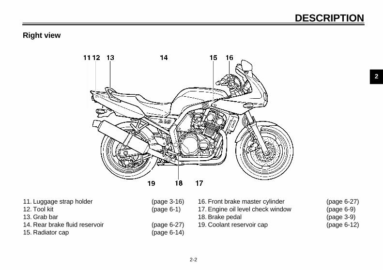
SCRIPTION
t view
Front fork spring preload adjusting bolt (page 3-13)Starter (choke) lever (page 3-12)Air filter element (page 6-17)Fuses (page 6-36)Storage compartment (page 3-13)Grab bar
7. Luggage strap holde8. Seat lock9. Rear shock absorbe
adjusting ring10. Shift pedal
DESCRIPTION
2
R
1112131415
cylinder (page 6-27)ck window (page 6-9)
(page 3-9)p (page 6-12)
E_5dm.book Page 2 Thursday, August 17, 2000 12:08 PM
2-2
ight view
. Luggage strap holder (page 3-16)
. Tool kit (page 6-1)
. Grab bar
. Rear brake fluid reservoir (page 6-27)
. Radiator cap (page 6-14)
16. Front brake master17. Engine oil level che18. Brake pedal19. Coolant reservoir ca

DE
2
Co
1.2.3.4.5.6.7.8.9.
E_5dm.book Page 3 Thursday, August 17, 2000 12:08 PM
SCRIPTION
2-3
ntrols and instruments
Clutch lever (page 3-8)Left handlebar switches (page 3-7)Speedometer unit (page 3-4)Main switch/steering lock (page 3-1)Tachometer (page 3-5)Fuel gauge (page 3-6)Right handlebar switches (page 3-8)Brake lever (page 3-9)Throttle grip (page 6-20)

3
INSTRUMENT AND CONTROL FUNCTIONS
Main switch/steering lock .....................................3-1Indicator and warning lights ................................3-3Speedometer unit ................................................3-4Tachometer ..........................................................3-5Self-diagnosis device ..........................................3-5Anti-theft alarm (optional) ....................................3-6Fuel gauge ...........................................................3-6Handlebar switches .............................................3-7Clutch lever ..........................................................3-8Shift pedal ............................................................3-9Brake lever ...........................................................3-9Brake pedal ..........................................................3-9
Fuel tank cap .................................................... 3-10Fuel ................................................................... 3-11Fuel tank breather hose .................................... 3-11Starter (choke) lever .......................................... 3-12Seat ................................................................... 3-12Storage compartment ....................................... 3-13Adjusting the front fork ...................................... 3-13Adjusting the shock absorber assembly ............ 3-14Luggage strap holders ...................................... 3-15Sidestand .......................................................... 3-15Ignition circuit cut-off system ............................. 3-16
E_5dm.book Page 1 Thursday, August 17, 2000 12:08 PM
3
EAU00027
E_5dm.book Page 1 Thursday, August 17, 2000 12:08 PM
3-IN
EW000016
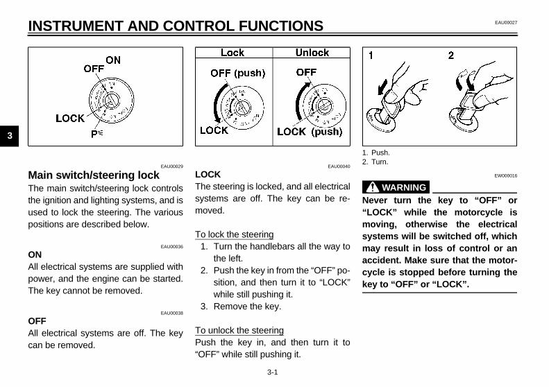
WARNINGer turn the key to “OFF” orCK” while the motorcycle isving, otherwise the electricaltems will be switched off, whichy result in loss of control or anident. Make sure that the motor-le is stopped before turning the to “OFF” or “LOCK”.
ush.urn.
MaThethe usepos
ONAll powThe
OFAll can
3-1
STRUMENT AND CONTROL FUNCTIONS
EAU00029
in switch/steering lock main switch/steering lock controlsignition and lighting systems, and isd to lock the steering. The variousitions are described below.
EAU00036
electrical systems are supplied wither, and the engine can be started. key cannot be removed.
EAU00038
Felectrical systems are off. The key be removed.
EAU00040
LOCKThe steering is locked, and all electricalsystems are off. The key can be re-moved.
To lock the steering1. Turn the handlebars all the way to
the left.2. Push the key in from the “OFF” po-
sition, and then turn it to “LOCK”while still pushing it.
3. Remove the key.
To unlock the steeringPush the key in, and then turn it to“OFF” while still pushing it.
@
Nev“LOmosysmaacccyckey@
1. P2. T

NTROL FUNCTIONS
3
ThanelbeThke
C@
Danw@
E_5dm.book Page 2 Thursday, August 17, 2000 12:08 PM
INSTRUMENT AND CO
3-2
EAU01316
(Parking)e steering is locked, and the taillightsd auxiliary light are on, but all other
ectrical systems are off. The key can removed.e steering must be locked before they can be turned to “ ”.
ECA00043
AUTION:o not use the parking position for extended length of time, other-
ise the battery may discharge.

IN
3
Ind
Tur“Thees pus
NeThitran
:if the oil level is sufficient, theg light may flicker when riding one or during sudden accelerationceleration, but this is not action.
EAU01716
nt temperature warning light
arning light comes on when the overheats. When this occurs,e engine immediately and allowgine to cool.
EC000002
ION:t operate the engine if it isated.
1. L2. N3. H4. O5. R6. C7. F
E_5dm.book Page 3 Thursday, August 17, 2000 12:08 PM
STRUMENT AND CONTROL FUNCTIONS
3-3
EAU03034
icator and warning lights
EAU03299
n signal indicator lights, ”
corresponding indicator light flash-when the turn signal switch ished to the left or right.
EAU00061
utral indicator light “ ” s indicator light comes on when thesmission is in the neutral position.
EAU00063
High beam indicator light “ ” This indicator light comes on when thehigh beam of the headlight is switchedon.
EAU03201
Oil level warning light “ ” This warning light comes on when theengine oil level is low.The electrical circuit of the warning lightcan be checked according to the fol-lowing procedure.
1. Set the engine stop switch to “ ”and turn the key to “ON”.
2. Shift the transmission into the neu-tral position or pull the clutch lever.
3. Push the start switch. If the warn-ing light does not come on whilepushing the start switch, have aYamaha dealer check the electri-cal circuit.
NOTE@
Even warnina slopor demalfun@
Coola“ ” This wenginestop ththe en
CAUT@
Do nooverhe@
eft turn indicator light “ ”eutral indicator light “ ”igh beam indicator light “ ”il level warning light “ ”ight turn indicator light “ ”oolant temperature warning light “ ”uel level warning light “ ”

NTROL FUNCTIONS
3
FuThfu3.asThcalo
1
2
3
N@
Thaginexde@
e on a tank of fuel. This informationll enable you to plan fuel stops in theture.
select a modesh the “SELECT” button to changetween the odometer mode “ODO” ,
e tripmeter modes “TRIP 1” andRIP 2”, and the clock mode in the fol-ing order:
DO” → “TRIP 1” → “TRIP 2” →ock → “ODO”
reset a meter reset either tripmeter 1 or 2 to 0.0,lect either by pushing the “SELECT”tton and push the “RESET” button
r at least one second.
ock mode change the display to the clock
ode, push both the “SELECT” andESET” buttons. change the display back to theometer mode, push the “SELECT”tton.
E_5dm.book Page 4 Thursday, August 17, 2000 12:08 PM
INSTRUMENT AND CO
3-4
EAU03509
el level warning light “ ”is warning light comes on when the
el level drops below approximately5 L. When this occurs, refuel as soon possible.e electrical circuit of the warning lightn be checked according to the fol-
wing procedure.. Set the engine stop switch to “ ”
and turn the key to “ON”. . Shift the transmission into the neu-
tral position or pull the clutch lever. . Push the start switch. If the warn-
ing light does not come on, have aYamaha dealer check the electri-cal circuit.
OTE:is model is equipped with a self-di-nosis device for the fuel level warn-
g light circuit. (See page 3-5 for anplanation of the self-diagnosisvice.)
EAU03028*
Speedometer unit This speedometer unit is equipped with:
● an odometer● two tripmeters● a clock
Odometer and tripmeter modesWhen set to “ODO”, the motorcycle’stotal mileage is indicated.When set to “TRIP 1” or “TRIP 2”, themotorcycle’s mileage since the tripme-ter was last reset is indicated. Use thetripmeters to estimate how far you can
ridwifu
ToPubeth“Tlow“OCl
ToTosebufo
ClTom“RToodbu
1. Speedometer2. Odometer/tripmeter/clock3. “SELECT” button4. “RESET” button

IN
3
To 1.
2.
3.
4.
5.
NO@
Aftthemaclo@
EAU01322
lf-diagnosis device s model is equipped with a self-di-osis device for the throttle positionsor circuit.e circuit is defective, the tachome-will repeatedly display the followingr code:
E
e tachometer displays such an er-code, have a Yamaha dealer check motorcycle.
EC000004
UTION:en the tachometer displays anr code, the motorcycle shouldchecked as soon as possible iner to avoid engine damage.
0 r/min for 3 seconds
3,000 r/min for 2.5 seconds
Current engine speed for 3 seconds
E_5dm.book Page 5 Thursday, August 17, 2000 12:08 PM
STRUMENT AND CONTROL FUNCTIONS
3-5
set the clockPush both the “SELECT” and“RESET” buttons for at least twoseconds.When the hour digits start flashing,push the “RESET” button to setthe hours.Push the “SELECT” button tochange the minutes.When the minute digits start flash-ing, push the “RESET” button toset the minutes.Push the “SELECT” button to startthe clock.
TE:er setting the clock, be sure to push “SELECT” button before turning thein switch to “OFF”, otherwise theck will not be set.
EAU00101
Tachometer The electric tachometer allows the riderto monitor the engine speed and keep itwithin the ideal power range.
EC000003
CAUTION:@
Do not operate the engine in the ta-chometer red zone.Red zone: 12,500 r/min and above @
SeThiagnsenIf thter erroCB-16
If thror the
CA@
Wherrobe ord@
1. Tachometer2. Red zone

NTROL FUNCTIONS
3
N@
If insocude@
EAU00110
el gauge e fuel gauge indicates the amount of
el in the fuel tank. The needle moveswards “E” (Empty) as the fuel levelcreases. When the needle reaches”, approximately 3.5 L of fuel remainthe fuel tank. If this occurs, refuel ason as possible.
TE: not allow the fuel tank to empty
elf completely.
Fuel gauge
E_5dm.book Page 6 Thursday, August 17, 2000 12:08 PM
INSTRUMENT AND CO
3-6
OTE:the tachometer displays 4,000 r/minstead of 3,000 r/min, the speed sen-r may be disconnected or short-cir-ited. If this occurs, have a Yamahaaler check the electrical circuit.
EAU00109
Anti-theft alarm (optional) This motorcycle can be equipped withan optional anti-theft alarm by aYamaha dealer. Contact a Yamahadealer for more information.
FuThfutode“Ein so
NO@
Doits@
1.

IN
3
Ha
PaPre
DimSebea
EC000006
UTION:not use the hazard light for an ex-ded length of time, otherwise thetery may discharge.
1. P2. D3. T4. H5. H
E_5dm.book Page 7 Thursday, August 17, 2000 12:08 PM
STRUMENT AND CONTROL FUNCTIONS
3-7
EAU00118
ndlebar switches
EAU00120
ss switch “PASS” ss this switch to flash the headlight.
EAU00121
mer switch t this switch to “ ” for the highm and to “ ” for the low beam.
EAU00127
Turn signal switch To signal a right-hand turn, push thisswitch to “ ”. To signal a left-handturn, push this switch to “ ”. Whenreleased, the switch returns to the cen-ter position. To cancel the turn signallights, push the switch in after it has re-turned to the center position.
EAU00129
Horn switch “ ” Press this switch to sound the horn.
EAU00144
Hazard switch “ ” With the key in the “ON” or “ ” posi-tion, use this switch to turn on the haz-ard light (simultaneous flashing of allturn signal lights).The hazard light is used in case of anemergency or to warn other driverswhen your motorcycle is stoppedwhere it might be a traffic hazard.
CA@
Do tenbat@
ass switch “PASS”immer switchurn signal switchorn switch “ ”azard switch “ ”

NTROL FUNCTIONS
3
EnSegiww
LiSeauligth
EAU00152
lutch lever e clutch lever is located at the leftndlebar grip. To disengage thetch, pull the lever toward the handle-r grip. To engage the clutch, release
e lever. The lever should be pulledpidly and released slowly for smoothtch operation.e clutch lever is equipped with atch switch, which is part of the ignitioncuit cut-off system. (See page 3-16r an explanation of the ignition circuitt-off system.)
1.2.3.
Clutch lever
E_5dm.book Page 8 Thursday, August 17, 2000 12:08 PM
INSTRUMENT AND CO
3-8
EAU00138
gine stop switch t this switch to “ ” to stop the en-
ne in case of an emergency, such ashen the motorcycle overturns orhen the throttle cable is stuck.
EAU00134
ght switch t this switch to “ ” to turn on thexiliary light, meter lighting and tail-ht. Set the switch to “ ” to turn one headlight also.
EAU00143
Start switch “ ” Push this switch to crank the enginewith the starter.
EC000005
CAUTION:@
See page 5-1 for starting instruc-tions prior to starting the engine. @
CThhaclubathracluThclucirfocu
Engine stop switchLight switchStart switch “ ”
1.

IN
3
ShThesidbinshistathis
EAU00162
pedal rake pedal is on the right side ofotorcycle. To apply the rear press down on the brake pedal.
1. S e pedal
E_5dm.book Page 9 Thursday, August 17, 2000 12:08 PM
STRUMENT AND CONTROL FUNCTIONS
3-9
EAU00157
ift pedal shift pedal is located on the left
e of the engine and is used in com-ation with the clutch lever whenfting the gears of the 6-speed con-nt-mesh transmission equipped on motorcycle.
EAU00161
Brake lever The brake lever is located at the righthandlebar grip. To apply the frontbrake, pull the lever toward the handle-bar grip.The brake lever is equipped with a po-sition adjusting dial. To adjust the dis-tance between the brake lever and thehandlebar grip, turn the adjusting dialwhile holding the lever pushed awayfrom the handlebar grip. Make sure thatthe appropriate setting on the adjustingdial is aligned with the arrow mark onthe brake lever.
BrakeThe bthe mbrake,
hift pedal 1. Brake lever2. Brake lever position adjusting dial3. Arrow marka. Distance between brake lever and handleber
grip
1. Brak

NTROL FUNCTIONS
3
F
ToOseit leop
To1
1.2.
E_5dm.book Page 10 Thursday, August 17, 2000 12:08 PM
INSTRUMENT AND CO
3-10
EAU02935
uel tank cap
open the fuel tank cappen the fuel tank cap lock cover, in-rt the key into the lock, and then turn
1/4 turn clockwise. The lock will be re-ased and the fuel tank cap can beened.
close the fuel tank cap. Push the fuel tank cap into posi-
tion with the key inserted in thelock.
2. Turn the key counterclockwise tothe original position, remove it,and then close the lock cover.
NOTE:@
The fuel tank cap cannot be closed un-less the key is in the lock. In addition,the key cannot be removed if the cap isnot properly closed and locked. @
EWA00025
WARNING@
Make sure that the fuel tank cap isproperly closed before riding. @
Fuel tank lock coverUnlock.

IN
3
FuMatheof illu
@
●
●
@
EAU02955
el tank breather hose ore operating the motorcycle:Check the fuel tank breather hoseconnection.Check the fuel tank breather hosefor cracks or damage, and replaceit if damaged.Make sure that the end of the fueltank breather hose is not blocked,and clean it if necessary.
1. F2. F
uel tank breather hose
E_5dm.book Page 11 Thursday, August 17, 2000 12:08 PM
STRUMENT AND CONTROL FUNCTIONS
3-11
EAU01183
el ke sure that there is sufficient fuel in tank. Fill the fuel tank to the bottomthe filler tube as shown in the
stration.EW000130
WARNINGDo not overfill the fuel tank, oth-erwise it may overflow when thefuel warms up and expands. Avoid spilling fuel on the hotengine.
EAU00185
CAUTION:@
Immediately wipe off spilled fuelwith a clean, dry, soft cloth, sincefuel may deteriorate painted surfac-es or plastic parts. @
EAU00191
NOTE:@
If knocking (or pinging) occurs, usegasoline of a different brand or with ahigher octane grade. @
FuBef
●
●
●
uel tank filler tubeuel level
Recommended fuel:Regular unleaded gasoline with a research octane number of 91 or higher
Fuel tank capacity:Total amount:
20 LReserve amount:
3.5 L
1. F

NTROL FUNCTIONS
3
SStaithMthMth
install the seat. Insert the projection on the rear of
the seat into the seat holder asshown.
. Push the front of the seat down tolock it in place.
. Remove the key.
TE:ake sure that the seat is properly se-red before riding.
1. ProjectionSeat holder
E_5dm.book Page 12 Thursday, August 17, 2000 12:08 PM
INSTRUMENT AND CO
3-12
EAU02976
tarter (choke) lever arting a cold engine requires a richerr-fuel mixture, which is supplied bye starter (choke).ove the lever in direction a to turn one starter (choke).ove the lever in direction b to turn offe starter (choke).
EAU01319
Seat
To remove the seat1. Insert the key into the seat lock,
and then turn it counterclockwise.2. While holding the key in that posi-
tion, lift the front of the seat up,and then pull the seat off.
To1
2
3
NO@
Mcu@
Starter (choke) lever 1. Seat lock2. Unlock.
1.2.

IN
3
StoThito (Ota Usectheparto p
EAU00285
justing the front fork s front fork is equipped with springload adjusting bolts.
EW000035
WARNINGays adjust both fork legs equal-therwise poor handling and losstability may result.
ust the spring preload as follows.
1. S pring preload adjusting bolt
E_5dm.book Page 13 Thursday, August 17, 2000 12:08 PM
STRUMENT AND CONTROL FUNCTIONS
3-13
EAU01688
rage compartment s storage compartment is designedhold a genuine Yamaha U-LOCK.her locks may not fit.) When placing-LOCK in the storage compartment,urely fasten it with the straps. When U-LOCK is not in the storage com-tment, be sure to secure the strapsrevent losing them.
When storing the owner’s manual orother documents in the storage com-partment, be sure to wrap them in aplastic bag so that they will not get wet.When washing the motorcycle, becareful not to let any water enter thestorage compartment.
AdThipre
@
Alwly, oof s@
Adj
torage compartment 1. U-LOCK2. Strap
1. S

NTROL FUNCTIONS
3
Tothetherecloasuea
NO@
Alijusfro@
CI-01
just the spring preload as follows. increase the spring preload andreby harden the suspension, turn adjusting ring in direction a. To de-ase the spring preload and therebyten the suspension, turn the adjust- ring in direction b.
TE:n the appropriate notch in the ad-
ting ring with the position indicatorthe shock absorber.
E
1. C2. F
Se
Minimum (soft)
Stan-dard
Maximum (hard)
tting 1 2 3 4 5 6 7 8 9
E_5dm.book Page 14 Thursday, August 17, 2000 12:08 PM
INSTRUMENT AND CO
3-14
increase the spring preload andreby harden the suspension, turn adjusting bolt on each fork leg in di-tion a. To decrease the spring pre-d and thereby soften thespension, turn the adjusting bolt onch fork leg in direction b.
TE:gn the appropriate groove on the ad-ting mechanism with the top of thent fork cap bolt.
E
EAU00295
Adjusting the shock absorber assembly This shock absorber assembly isequipped with a spring preload adjust-ing ring.
EC000015
CAUTION:@
Never attempt to turn an adjustingmechanism beyond the maximumor minimum settings. @
AdTothethecresofing
NO@
Aligjuson @
CI-01
urrent settingront fork cap
Minimum (soft)
Stan-dard
Maximum (hard)
tting 7 6 5 4 3 2 1
1. Spring preload adjusting ring2. Special wrench
Se

IN
3
@
Thily prostaforeThespoperimp
●
●
●
●
@
EAU00330
estand sidestand is located on the left side
the frame. Raise the sidestand orer it with your foot while holding thetorcycle upright.
TE: built-in sidestand switch is part of
ignition circuit cut-off system, whichs the ignition in certain situations.e further down for an explanation of ignition circuit cut-off system.)
E_5dm.book Page 15 Thursday, August 17, 2000 12:08 PM
STRUMENT AND CONTROL FUNCTIONS
3-15
EAU00315
WARNINGs shock absorber contains high-pressurized nitrogen gas. Forper handling, read and under-nd the following information be- handling the shock absorber. manufacturer cannot be held re-nsible for property damage orsonal injury that may result fromroper handling.Do not tamper with or attempt toopen the gas cylinder.Do not subject the shock ab-sorber to an open flame or otherhigh heat sources, otherwise itmay explode due to excessivegas pressure.Do not deform or damage thegas cylinder in any way, as thiswill result in poor damping per-formance.Always have a Yamaha dealerservice the shock absorber.
EAU01311
Luggage strap holders There are two luggage strap holdersbelow the rear of the seat, which canbe turned out for easier access.
SidTheof lowmo
NO@
Thethecut(Sethe@
1. Luggage strap holder (× 2)

NTROL FUNCTIONS
3
@
Thwsimerthtococuasrestchscdepr@
EW000046
WARNING● The vehicle must be placed on
the centerstand during thisinspection.
● If a malfunction is noted, have aYamaha dealer check the sys-tem before riding.
E_5dm.book Page 16 Thursday, August 17, 2000 12:08 PM
INSTRUMENT AND CO
3-16
EW000044
WARNINGe motorcycle must not be ridden
ith the sidestand down, or if thedestand cannot be properlyoved up (or does not stay up), oth-wise the sidestand could contacte ground and distract the opera-r, resulting in a possible loss ofntrol. Yamaha’s ignition circuitt-off system has been designed tosist the operator in fulfilling thesponsibility of raising the side-and before starting off. Therefore,eck this system regularly as de-ribed below and have a Yamahaaler repair it if it does not functionoperly.
EAU00332
Ignition circuit cut-off system The ignition circuit cut-off system (com-prising the sidestand switch, clutchswitch and neutral switch) has the fol-lowing functions.
● It prevents starting when the trans-mission is in gear and the side-stand is up, but the clutch lever isnot pulled.
● It prevents starting when the trans-mission is in gear and the clutchlever is pulled, but the sidestand isstill down.
● It cuts the running engine whenthe sidestand is moved down.
Periodically check the operation of theignition circuit cut-off system accordingto the following procedure.
@
@

IN
3
CD-0
itch may be defective.le should not be ridden until Yamaha dealer.
switch may be defective.le should not be ridden until Yamaha dealer.
itch may be defective.le should not be ridden until Yamaha dealer.
ost reliable if performed withengine.
E_5dm.book Page 17 Thursday, August 17, 2000 12:08 PM
STRUMENT AND CONTROL FUNCTIONS
3-17
1E
With the engine turned off:1. Move the sidestand down.2. Make sure that the engine stop switch is set to “ ”.3. Turn the key to “ON”. 4. Shift the transmission into the neutral position.5. Push the start switch.Does the engine start?
The neutral swThe motorcycchecked by a
With the engine still running:6. Move the sidestand up.7. Keep the clutch lever pulled.8. Shift the transmission into gear.9. Move the sidestand down.Does the engine stall?
After the engine has stalled:10. Move the sidestand up.11. Keep the clutch lever pulled.12. Push the start switch.Does the engine start?
The sidestandThe motorcycchecked by a
The clutch swThe motorcycchecked by a
NO
NOTE:This check is ma warmed-up
YES
YES NO
The system is OK. The motorcycle can be ridden.
YES NO

PRE-OPERATION CHECKS
4
Pre-operation check list ..................................................................... 4-1
E_5dm.book Page 1 Thursday, August 17, 2000 12:08 PM

4
EAU01114
teriorate quickly and unexpectedly,). Any damage, fluid leakage or lossddition to a thorough visual inspec-
E_5dm.book Page 1 Thursday, August 17, 2000 12:08 PM
4-PR
Theeveof ti
EAU03328
PAGE
6-25–6-28
6-24–6-25
6-20, 6-30
6-9–6-12
6-12–6-16
6-28–6-30
6-21–6-246-39–6-42
6-30
6-31
6-32
tion
Fro
Re
Clu
Th
En
Co
Dri
Wh
Co
Brasha
Brapiv
4-1
E-OPERATION CHECKS
condition of a vehicle is the owner’s responsibility. Vital components can start to den if the vehicle remains unused (for example, as a result of exposure to the elementsre air pressure could have serious consequences. Therefore, it is very important, in a, to check the following points before each ride.
Pre-operation check list
ITEM CHECKS
nt brake • Check operation, free play, fluid level and fluid leakage.• Fill with DOT 4 brake fluid if necessary.ar brake
tch • Check operation condition and free play.• Adjust if necessary.
rottle grip and housing • Check for smooth operation.• Lubricate if necessary.
gine oil • Check oil level.• Fill with oil if necessary.
olant reservoir tank • Check coolant level.• Fill with coolant if necessary.
ve chain • Check chain slack and condition.• Adjust if necessary.
eels and tires • Check tire pressure, wear and damage.
ntrol cables • Check smooth operation. • Lubricate if necessary.
ke and shift pedal fts
• Check smooth operation. • Lubricate if necessary.
ke and clutch lever ots
• Check smooth operation. • Lubricate if necessary.
PERATION CHECKS
4N@
Pr ection can be accomplished in a verysh@
EWA00033
@
If d repaired before operatingth@
Cp 6-32
C ed. —
F 3-10–3-11
Ls —
PAGE
E_5dm.book Page 2 Thursday, August 17, 2000 12:08 PM
PRE-O
4-2
OTE:e-operation checks should be made each time the motorcycle is used. Such an insport time; and the added safety it assures is more than worth the time involved.
WARNINGany item in the Pre-operation check list is not working properly, have it inspected ane motorcycle.
enter and sidestand ivots
• Check smooth operation. • Lubricate if necessary.
hassis fasteners • Make sure that all nuts, bolts and screws are properly tighten• Tighten if necessary.
uel • Check fuel level.• Fill with fuel if necessary.
ights, signals and witches • Check proper operation.
ITEM CHECKS

E_5dm.book Page 3 Thursday, August 17, 2000 12:08 PM

OPERATION AND IMPORTANT RIDING POINTS
5
Starting a cold engine ....................................................................... 5-1Starting a warm engine ..................................................................... 5-3Shifting .............................................................................................. 5-3Recommended shift points (for Switzerland only) ............................. 5-4Tips for reducing fuel consumption ................................................... 5-4Engine break-in ................................................................................. 5-4Parking .............................................................................................. 5-5
E_5dm.book Page 1 Thursday, August 17, 2000 12:08 PM

5
EAU00372
Turn the key to “ON” and makesure that the engine stop switch isset to “ ”.
E_5dm.book Page 1 Thursday, August 17, 2000 12:08 PM
5-OP
@
●
EC000035
UTION:e fuel level warning light comes
check the fuel level, and, if nec-ary, refuel as soon as possible.
Shift the transmission into the neu-tral position.
TE:en the transmission is in the neutralition, the neutral indicator lightuld be on, otherwise have aaha dealer check the electrical cir-
.
Turn the starter (choke) on andcompletely close the throttle. (Seepage 3-12 for starter (choke) oper-ation.)Start the engine by pushing thestart switch.
●
●
@
5-1
ERATION AND IMPORTANT RIDING POINTSEAU00373
WARNINGBecome thoroughly familiarwith all operating controls andtheir functions before riding.Consult a Yamaha dealer re-garding any control or functionthat you do not thoroughlyunderstand.Never start the engine or oper-ate it in a closed area for anylength of time. Exhaust fumesare poisonous, and inhalingthem can cause loss of con-sciousness and death within ashort time. Always make surethat there is adequate ventila-tion.Before starting out, make surethat the sidestand is up. If thesidestand is not raised com-pletely, it could contact theground and distract the opera-tor, resulting in a possible lossof control.
EAU01627
Starting a cold engine In order for the ignition circuit cut-offsystem to enable starting, one of thefollowing conditions must be met:
● The transmission is in the neutralposition.
● The transmission is in gear withthe clutch lever pulled and thesidestand up.
EW000054
WARNING@
● Before starting the engine,check the function of the igni-tion circuit cut-off system ac-cording to the proceduredescribed on page 3-16.
● Never ride with the sidestanddown.
@
1.
CA@
If thon,ess@
2.
NO@
WhposshoYamcuit@
3.
4.

ANT RIDING POINTS
5
N@
If stthshsegiat@
C@
. When the engine is warm, turn thestarter (choke) off.
TE:e engine is warm when it respondsrmally to the throttle with the starter
hoke) turned off.
E_5dm.book Page 2 Thursday, August 17, 2000 12:08 PM
OPERATION AND IMPORT
5-2
OTE:the engine fails to start, release theart switch, wait a few seconds, anden try again. Each starting attemptould be as short as possible to pre-rve the battery. Do not crank the en-
ne more than 10 seconds on any onetempt.
EC000038
AUTION:● The oil level warning light and
fuel level warning light shouldcome on when the start switchis pushed, and they should gooff when the start switch isreleased.
● If the oil level warning light flick-ers or remains on after starting,immediately stop the engine,and then check the engine oillevel and the vehicle for oil leak-age. If necessary, add engineoil, and then check the warninglight again. If the warning lightdoes not come on when push-ing the start switch, or if it does
not go off after starting with suf-ficient engine oil, have aYamaha dealer check the elec-trical circuit.
● If the fuel level warning light re-mains on after starting, stop theengine, and then check the fuellevel. If necessary, refuel assoon as possible, and thencheck the warning light again. Ifthe warning light does not comeon when pushing the startswitch, or if it does not go off af-ter starting with sufficient fuel,have a Yamaha dealer check theelectrical circuit.
@
5. After starting the engine, move thestarter (choke) knob/lever backhalfway.
ECA00045
CAUTION:@
For maximum engine life, never ac-celerate hard when the engine iscold! @
6
NO@
Thno(c@
O
5
StaFolingthawh
EC000048
UTION:Even with the transmission inthe neutral position, do notcoast for long periods of timewith the engine off, and do nottow the motorcycle for long dis-tances. The transmission isproperly lubricated only whenthe engine is running. Inade-quate lubrication may damagethe transmission.Always use the clutch whilechanging gears to avoid dam-aging the engine, transmission,and drive train, which are notdesigned to withstand theshock of forced shifting.
E_5dm.book Page 3 Thursday, August 17, 2000 12:08 PM
PERATION AND IMPORTANT RIDING POINTS
5-3
EAU01258
rting a warm engine low the same procedure as for start- a cold engine with the exceptiont the starter (choke) is not requireden the engine is warm.
EAU00423
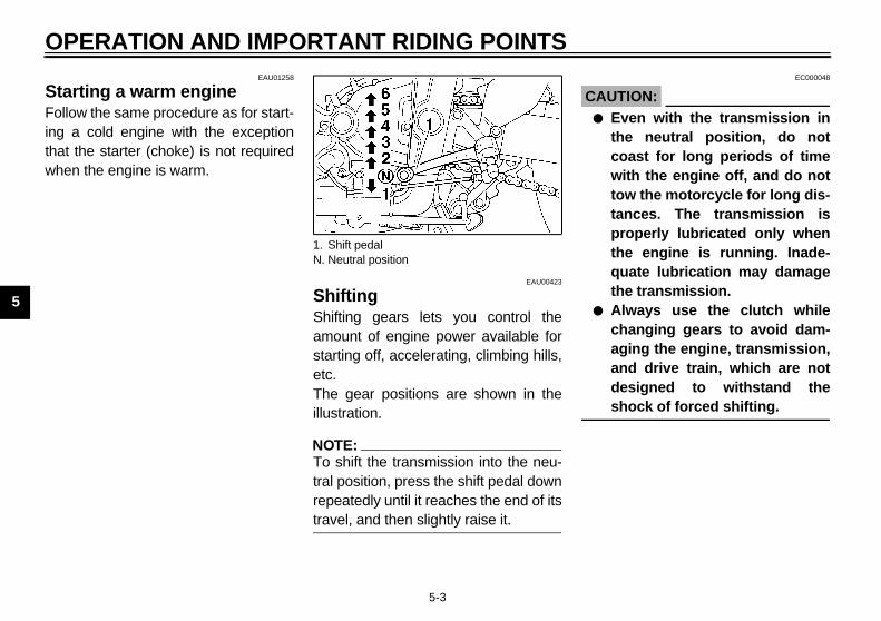
Shifting Shifting gears lets you control theamount of engine power available forstarting off, accelerating, climbing hills,etc.The gear positions are shown in theillustration.
NOTE:@
To shift the transmission into the neu-tral position, press the shift pedal downrepeatedly until it reaches the end of itstravel, and then slightly raise it. @
CA@
●
●
@
1. Shift pedalN. Neutral position

ANT RIDING POINTS
5
R(fThacloCF
N@
Wtim(efro@
EAU01128
ngine break-in ere is never a more important periodthe life of your engine than the periodtween 0 and 1,600 km. For this rea-n, you should read the following ma-rial carefully.nce the engine is brand new, do nott an excessive load on it for the first
600 km. The various parts in the en-e wear and polish themselves to therrect operating clearances. Duringis period, prolonged full-throttle oper-ion or any condition that might resultengine overheating must be avoided.
E_5dm.book Page 4 Thursday, August 17, 2000 12:08 PM
OPERATION AND IMPORT
5-4
EAU02937
ecommended shift points or Switzerland only) e recommended shift points duringceleration are shown in the table be-
w.-02E
OTE:hen shifting down two gears at ae, reduce the speed accordingly
.g., down to 35 km/h when shiftingm 5th to 3rd gear).
EAU00424
Tips for reducing fuel consumption Fuel consumption depends largely onyour riding style. Consider the followingtips to reduce fuel consumption:
● Thoroughly warm up the engine.● Turn the starter (choke) off as
soon as possible.● Shift up swiftly, and avoid high en-
gine speeds during acceleration.● Do not rev the engine while shift-
ing down, and avoid high enginespeeds with no load on the engine.
● Turn the engine off instead of let-ting it idle for an extended lengthof time (e.g., in traffic jams, at traf-fic lights or at railroad crossings).
EThin besoteSipu1,gincothatin
Shift point(km/h)
1st → 2nd2nd → 3rd3rd → 4th4th → 5th5th → 6th
2030405060

O
5
0–1Avo5,0
1,0Avo6,0
CA@
Aftginfilte@
1,6Thenor
CA@
●
●
@
E_5dm.book Page 5 Thursday, August 17, 2000 12:08 PM
PERATION AND IMPORTANT RIDING POINTS
5-5
EAU01329
,000 kmid prolonged operation above
00 r/min.
00–1,600 kmid prolonged operation above
00 r/min.EC000052
UTION:er 1,000 km of operation, the en-e oil must be changed and the oilr cartridge/element replaced.
00 km and beyond vehicle can now be operated
mally.EC000053
UTION:Keep the engine speed out ofthe tachometer red zone.If any engine trouble should oc-cur during the engine break-inperiod, immediately have aYamaha dealer check the vehicle.
EAU00460
Parking When parking, stop the engine, andthen remove the key from the mainswitch.
EW000058
WARNING@
● Since the engine and exhaustsystem can become very hot,park in a place where pedestri-ans or children are not likely totouch them.
● Do not park on a slope or onsoft ground, otherwise themotorcycle may overturn.
@

6
PERIODIC MAINTENANCE AND MINOR REPAIR
Owner’s tool kit ....................................................6-1Periodic maintenance and lubrication chart .........6-2Removing and installing panels ...........................6-5Checking the spark plugs ....................................6-7Engine oil and oil filter cartridge ..........................6-9Coolant ..............................................................6-12Air filter ..............................................................6-17Adjusting the carburetors ...................................6-19Adjusting the engine idling speed ......................6-19Adjusting the throttle cable free play ..................6-20Adjusting the valve clearance ............................6-20Tires ...................................................................6-21Wheels ...............................................................6-24Adjusting the clutch lever free play ....................6-24Adjusting the brake pedal position .....................6-25Adjusting the rear brake light switch ..................6-26Checking the front and rear brake pads .............6-26Checking the brake fluid level ............................6-27Changing the brake fluid ....................................6-28Drive chain slack ................................................6-28Lubricating the drive chain .................................6-29Checking and lubricating the cables ..................6-30
Checking and lubricating the throttle grip and cable ................................................. 6-31
Checking and lubricating the brake and shift pedals ..................................... 6-31
Checking and lubricating the brake and clutch levers ............................................. 6-32
Checking and lubricating the centerstand and sidestand .................................................. 6-32
Lubricating the rear suspension ........................ 6-33Checking the front fork ...................................... 6-33Checking the steering ....................................... 6-34Checking the wheel bearings ............................ 6-34Battery ............................................................... 6-35Replacing the fuses .......................................... 6-36Replacing the headlight bulb ............................. 6-37Replacing the tail/brake light bulb ..................... 6-38Replacing a turn signal light bulb ...................... 6-39Front wheel ....................................................... 6-39Rear wheel ........................................................ 6-41Troubleshooting ................................................. 6-43Troubleshooting charts ...................................... 6-44
E_5dm.book Page 1 Thursday, August 17, 2000 12:08 PM

6
EAU00462
TE:ou do not have the tools or experi-e required for a particular job, have
E_5dm.book Page 1 Thursday, August 17, 2000 12:08 PM
6-PE
SafPer
amaha dealer perform it for you.
EW000063
WARNINGdifications not approved by
aha may cause loss of perfor-nce and render the vehicle unsafeuse. Consult a Yamaha dealer be- attempting any changes.
bricsafesiblspeareThemashoerationWECAUSVALSHO
@
If ycycYam@
6-1
RIODIC MAINTENANCE AND MINOR REPAIR EAU00464
ety is an obligation of the owner.iodic inspection, adjustment and lu-ation will keep your vehicle in thest and most efficient condition pos-
e. The most important points of in-ction, adjustment, and lubrication explained on the following pages. intervals given in the periodic
intenance and lubrication chartuld be simply considered as a gen-l guide under normal riding condi-s. However, DEPENDING ON THEATHER, TERRAIN, GEOGRAPHI-L LOCATION, AND INDIVIDUALE, THE MAINTENANCE INTER-S MAY NEED TO BERTENED.
EW000060
WARNINGou are not familiar with motor-le maintenance work, have aaha dealer do it for you.
EAU01299
Owner’s tool kit The owner’s tool kit is located insidethe storage compartment under theseat. (See page 3-12 for seat removalprocedures.)The service information included in thismanual and the tools provided in theowner’s tool kit are intended to assistyou in the performance of preventivemaintenance and minor repairs. How-ever, additional tools such as a torquewrench may be necessary to performcertain maintenance work correctly.
NO@
If yenca Y@
@
MoYammafor fore@
1. Tool kit

AND MINOR REPAIR
6
EAU03540
N@
enance is performed instead.
equire special tools, data and techni-
@
CP
NETER READING (×1,000 km) Annual
check10 20 30 40
1 √ √ √ √ √
2 √ √
3√ √
√ √
4 Every 40,000 km
5√ √
√ √
6 √ √ √ √
7√ √ √ √ √
Whenever worn to the limit
8√ √ √ √ √
Whenever worn to the limit
9√ √ √ √ √
Every 4 years
E_5dm_Periodic.fm Page 2 Tuesday, December 19, 2000 8:47 AM
PERIODIC MAINTENANCE
6-2
Periodic maintenance and lubrication chart
OTE:● The annual checks must be performed every year, except if a kilometer-based maint● From 50,000 km, repeat the maintenance intervals starting from 10,000 km. ● Items marked with an asterisk should be performed by a Yamaha dealer as they r
cal skills.
-01E
O. ITEM CHECK OR MAINTENANCE JOBODOM
1
* Fuel line • Check fuel hoses for cracks or damage.
* Fuel filter • Check condition.
Spark plugs• Check condition.• Clean and regap.
• Replace.
* Valves • Check valve clearance.• Adjust.
Air filter element• Clean.
• Replace.
Clutch • Check operation.• Adjust. √
* Front brake• Check operation, fluid level and vehicle for fluid leakage.
(See NOTE on page 6-4.) √
• Replace brake pads.
* Rear brake• Check operation, fluid level and vehicle for fluid leakage.
(See NOTE on page 6-4.) √
• Replace brake pads.
* Brake hoses• Check for cracks or damage.
• Replace. (See NOTE on page 6-4.)

PE
6
10 √ √ √ √
11 √ √ √ √
12 √ √ √ √
13√ √ √ √
Every 50,000km
14 Every 1,000 km and after washinghe motorcycle or riding in the rain.
15√ √ √ √
Every 20,000km
16 √ √ √ √ √
17 √ √ √ √ √
18 √ √ √ √ √
19 √ √ √ √
20 √ √ √ √
21√ √ √ √
√ √
22 √ √ √ √ √
23 √ √ √ √ √
24 √ √
NOTER READING (×1,000 km) Annual
check10 20 30 40
E_5dm_Periodic.fm Page 3 Tuesday, December 19, 2000 8:47 AM
RIODIC MAINTENANCE AND MINOR REPAIR
6-3
* Wheels • Check runout and for damage.
* Tires
• Check tread depth and for damage.• Replace if necessary.• Check air pressure.• Correct if necessary.
* Wheel bearings • Check bearing for looseness or damage.
* Swingarm• Check operation and for excessive play.
• Lubricate with molybdenum disulfide grease.
Drive chain• Check chain slack.• Make sure that the rear wheel is properly aligned.• Clean and lubricate. t
* Steering bearings• Check bearing play and steering for roughness. √• Lubricate with lithium-soap-based grease.
* Chassis fasteners • Make sure that all nuts, bolts and screws are properly tightened.
Sidestand/centerstand • Check operation.• Lubricate.
* Sidestand switch • Check operation. √
* Front fork • Check operation and for oil leakage.
*Rear shock absorber assembly • Check operation and shock absorber for oil leakage.
*Rear suspension relay arm and connecting arm pivoting points
• Check operation.
• Lubricate with molybdenum disulfide grease.
* Carburetors • Check starter (choke) operation.• Adjust engine idling speed and synchronization. √
Engine oil • Change. √
Engine oil filter cartridge • Replace. √
. ITEM CHECK OR MAINTENANCE JOBODOME
1

AND MINOR REPAIR
6
EAU03884
N_
y areas.
and calipers, and change the brake
_
25√ √ √ √ √
Every 3 years
26 √ √ √ √ √
27 √ √ √ √ √
28 √ √ √ √ √
NETER READING (×1,000 km) Annual
check10 20 30 40
E_5dm_Periodic.fm Page 4 Tuesday, December 19, 2000 8:47 AM
PERIODIC MAINTENANCE
6-4
OTE:● The air filter needs more frequent service if you are riding in unusually wet or dust● Hydraulic brake service
• Regularly check and, if necessary, correct the brake fluid level.• Every two years replace the internal components of the brake master cylinders
fluid.• Replace the brake hoses every four years and if cracked or damaged.
* Cooling system• Check coolant level and vehicle for coolant leakage.
• Change.
*Front and rear brake switches • Check operation. √
Moving parts and cables • Lubricate.
*Lights, signals and switches
• Check operation.• Adjust headlight beam. √
O. ITEM CHECK OR MAINTENANCE JOBODOM
1

PE
6
RepaTheremtenRenee
EAU00491
el A, Cremove the panel
ove the bolt, and then pull the pan-ff as shown.
install the panelce the panel in the original position, then install the bolt.
1. P2. P
anel Aolt
E_5dm.book Page 5 Thursday, August 17, 2000 12:08 PM
RIODIC MAINTENANCE AND MINOR REPAIR
6-5
EAU01122
moving and installing nels panels shown above need to beoved to perform some of the main-
ance jobs described in this chapter.fer to this section each time a panelds to be removed and installed.
PanTo Remel o
To Plaand
anel Aanel B
1. Panel C 1. P2. B

AND MINOR REPAIR
6
1.2.
E_5dm.book Page 6 Thursday, August 17, 2000 12:08 PM
PERIODIC MAINTENANCE
6-6
EAU01315
Panel BTo remove the panelRemove the screws, and then take thepanel off.
To install the panelPlace the panel in the original position,and then install the screws.
Panel CBolt
1. Panel B2. Screw (× 3)

PE
6
ChThecomSinspapluin ananthevea
TE:ny spark plug shows a distinctly dif-nt color, the engine could be defec-. Do not attempt to diagnose suchblems yourself. Instead, have a
aha dealer check the motorcycle.
Check each spark plug for elec-trode erosion and excessive car-bon or other deposits, and replaceit if necessary.
1. S
pecified spark plug:Except for D, F
CR8E, CR9E (NGK) orU24ESR-N, U27ESR-N(DENSO)
For D, FCR7E, CR8E, CR9E (NGK) orU22ESR-N, U24ESR-N,U27ESR-N (DENSO)
E_5dm.book Page 7 Thursday, August 17, 2000 12:08 PM
RIODIC MAINTENANCE AND MINOR REPAIR
6-7
EAU03329
ecking the spark plugs spark plugs are important engineponents, which are easy to check.
ce heat and deposits will cause anyrk plug to slowly erode, the spark
gs should be removed and checkedccordance with the periodic mainte-ce and lubrication chart. In addition,
condition of the spark plugs can re-l the condition of the engine.
To remove a spark plug1. Remove the spark plug cap.2. Remove the spark plug as shown,
with the spark plug wrench includ-ed in the owner’s tool kit.
To check the spark plugs1. Check that the porcelain insulator
around the center electrode oneach spark plug is a medium-to-light tan (the ideal color when themotorcycle is ridden normally).
2. Check that all spark plugs installedin the engine have the same color.
NO@
If aferetiveproYam@
3.
park plug cap 1. Spark plug wrench
S

AND MINOR REPAIR
6
To1
2
a.
E_5dm.book Page 8 Thursday, August 17, 2000 12:08 PM
PERIODIC MAINTENANCE
6-8
install a spark plug. Measure the spark plug gap with a
wire thickness gauge and, if nec-essary, adjust the gap tospecification.
. Clean the surface of the sparkplug gasket and its mating sur-face, and then wipe off any grimefrom the spark plug threads.
3. Install the spark plug with thespark plug wrench, and then tight-en it to the specified torque.
NOTE:@
If a torque wrench is not available wheninstalling a spark plug, a good estimateof the correct torque is 1/4–1/2 turnpast finger tight. However, the sparkplug should be tightened to the speci-fied torque as soon as possible. @
4. Install the spark plug cap.
Spark plug gap
Spark plug gap:0.7–0.8 mm
Tightening torque:Spark plug:
12.5 Nm (1.25 m·kg)

PE
6
EncaThebefmutridfiedlub
change the engine oil (with orout oil filter cartridge replace-
nt)Start the engine, warm it up forseveral minutes, and then turn itoff.Place an oil pan under the engineto collect the used oil.
1. E2. M3. M
ngine oil filler cap
E_5dm.book Page 9 Thursday, August 17, 2000 12:08 PM
RIODIC MAINTENANCE AND MINOR REPAIR
6-9
EAU01717
gine oil and oil filter rtridge engine oil level should be checked
ore each ride. In addition, the oilst be changed and the oil filter car-ge replaced at the intervals speci- in the periodic maintenance andrication chart.
To check the engine oil level1. Place the motorcycle on the
centerstand.
NOTE:@
Make sure that the motorcycle is posi-tioned straight up when checking the oillevel. A slight tilt to the side can result ina false reading. @
2. Start the engine, warm it up forseveral minutes, and then turn itoff.
3. Wait a few minutes until the oil set-tles, and then check the oil levelthrough the check window locatedat the bottom-right side of thecrankcase.
NOTE:@
The engine oil should be between theminimum and maximum level marks. @
4. If the engine oil is below the mini-mum level mark, add sufficient oilof the recommended type to raiseit to the correct level.
To withme
1.
2.
ngine oil level check windowaximum level markinimum level mark
1. E

AND MINOR REPAIR
6
3
N@
@
. Apply a thin coat of engine oil tothe O-ring of the new oil filtercartridge.
TE:ake sure that the O-ring is properlyated.
1. O-ring
E_5dm.book Page 10 Thursday, August 17, 2000 12:08 PM
PERIODIC MAINTENANCE
6-10
. Remove the engine oil filler capand drain bolt to drain the oil fromthe crankcase.
OTE:● When draining the engine oil, use
a funnel or similar device to keepthe oil away from the exhaust pipe.
● Skip steps 4–6 if the oil filter car-tridge is not being replaced.
4. Remove the oil filter cartridge withan oil filter wrench.
NOTE:@
An oil filter wrench is available at aYamaha dealer. @
5
NO@
Mse@
Engine oil drain bolt 1. Oil filter wrench2. Oil filter cartridge
1.

PE
6
6.
7.
EC000072
UTION:In order to prevent clutch slip-page (since the engine oil alsolubricates the clutch), do notmix any chemical additiveswith the oil or use oils of ahigher grade than “CD”. In ad-dition, do not use oils labeled“ENERGY CONSERVING II” orhigher.Make sure that no foreign mate-rial enters the crankcase.
Start the engine, and then let it idlefor several minutes while checkingit for oil leakage. If oil is leaking,immediately turn the engine offand check for the cause.
TE:r the engine is started, the engine
evel warning light should go off if theevel is sufficient.
1. T
T
T
E_5dm.book Page 11 Thursday, August 17, 2000 12:08 PM
RIODIC MAINTENANCE AND MINOR REPAIR
6-11
Install the new oil filter cartridge,and then tighten it to the specifiedtorque with a torque wrench.
Install the engine oil drain bolt, andthen tighten it to the specifiedtorque.
8. Add the specified amount of therecommended engine oil, andthen install and tighten the oil fillercap.
CA@
●
●
@
9.
NO@
Afteoil loil l@
orque wrench
ightening torque:Oil filter cartridge:
17 Nm (1.7 m·kg)
ightening torque:Engine oil drain bolt:
43 Nm (4.3 m·kg)
Recommended engine oil:See page 8-1.
Oil quantity:Without oil filter cartridge replacement:
2.5 LWith oil filter cartridge replacement:
2.7 LTotal amount (dry engine):
3.5 L

ND MINOR REPAIR
6
C@
If orener@
10
emove panel A. (See page 6-5or panel removal and installationrocedures.)heck the coolant level in theoolant reservoir.
:coolant should be between theum and maximum level marks.
f the coolant is at or below theinimum level mark, open the res-rvoir cap, add coolant to the max-
mum level mark, and then closehe reservoir cap.
olant reservoir capacity:0.61 L
E_5dm.book Page 12 Thursday, August 17, 2000 12:08 PM
PERIODIC MAINTENANCE A
6-12
EC000067
AUTION:the oil level warning light flickers remains on, immediately turn thegine off and have a Yamaha deal- check the vehicle.
. Turn the engine off, and thencheck the oil level and correct it ifnecessary.
EAU01718
Coolant
To check the coolant level 1. Place the motorcycle on a level
surface and hold it in an uprightposition.
NOTE:@
● The coolant level must be checkedon a cold engine since the levelvaries with engine temperature.
● Make sure that the motorcycle is po-sitioned straight up when checkingthe coolant level. A slight tilt to theside can result in a false reading.
@
2. Rfp
3. Cc
NOTE@
The minim@
4. Imeit
1. Coolant reservoir2. Maximum level mark3. Minimum level mark
Co

PE
6
CA@
●
●
●
@
@
Netor @
5.
EAU03585
change the coolant Place the motorcycle on the cen-terstand and let the engine cool ifnecessary.Remove the seat. (See page 3-12for seat removal and installationprocedures.)Remove the fuel tank bolts.
olt (× 2)
E_5dm.book Page 13 Thursday, August 17, 2000 12:08 PM
RIODIC MAINTENANCE AND MINOR REPAIR
6-13
EC000080
UTION:If coolant is not available, usedistilled water or soft tap waterinstead. Do not use hard wateror salt water since it is harmfulto the engine. If water has been used insteadof coolant, replace it with cool-ant as soon as possible, other-wise the engine may not besufficiently cooled and the cool-ing system will not be protectedagainst frost and corrosion. If water has been added to thecoolant, have a Yamaha dealercheck the antifreeze content ofthe coolant as soon as possible,otherwise the effectiveness ofthe coolant will be reduced.
EW000067
WARNINGver attempt to remove the radia-cap when the engine is hot.
Install the panel.
NOTE:@
The radiator fan is automaticallyswitched on or off according to thecoolant temperature in the radiator. Ifthe engine overheats, see page 6-44for further instructions. @
To 1.
2.
3.
1. B

AND MINOR REPAIR
6
4
5
6
EW000067
WARNINGver attempt to remove the radia-
r cap when the engine is hot.
. Remove the coolant reservoir cap.
. Disconnect the radiator overflowhose from the top of the radiator.
1.2.3.
Radiator capRadiator overflow hose
E_5dm.book Page 14 Thursday, August 17, 2000 12:08 PM
PERIODIC MAINTENANCE
6-14
. Lift the fuel tank, and then turn thefuel cock lever to “OFF”.
. Disconnect the fuel level sensorcoupler.
. Pull the hose off the fuel tank andfuel cock, and then remove thetank.
7. Remove the sidestand switch leadfrom the holder.
8. Place a container under the en-gine to collect the used coolant.
9. Remove the water pump drain boltto drain the water pump housing.
10. Make a guide using paper or card-board or some other type of mate-rial, hold it under the coolant drainhole, and then remove the radiatorcap to drain the remaining coolant.
@
Neto@
1112
HoseFuel cockFuel level sensor coupler
1. Water pump drain bolt2. Sidestand switch lead3. Lead holder4. Funnel
1.2.

PE
6
13.
TE:ck the washer for damage and re-
ce it if necessary.
Connect the radiator overflowhose and make sure that it is prop-erly routed.Pour the recommended coolantinto the radiator until it is full.
1. H
ightening torque:Coolant drain bolt:
10 Nm (1,0 m·kg)
ecommended antifreeze:High-quality ethylene glycol antifreeze containing corrosioninhibitors for aluminum engines
ntifreeze/water mixture ratio:1:1
oolant quantity:Total amount:
1,95 LCoolant reservoir capacity:
0,61 L
E_5dm.book Page 15 Thursday, August 17, 2000 12:08 PM
RIODIC MAINTENANCE AND MINOR REPAIR
6-15
Pull the hose holder off the frame. 14. Pull the hose down and to the out-side while making sure to keep theend up, and then tilt the hosedownward into the container todrain the coolant reservoir.
NOTE:@
Note the original routing of the radiatoroverflow hose to ensure proper instal-lation later on. @
15. After the coolant is completelydrained, thoroughly flush the cool-ing system with clean tap water.
16. Install the coolant drain bolt, andthen tighten it to the specifiedtorque.
NO@
Chepla@
17.
18.
ose holder
T
R
A
C

AND MINOR REPAIR
6
C@
@
19
. Install the radiator cap and reser-voir cap, start the engine, and thencheck the vehicle for coolant leak-age. If coolant is leaking, have aYamaha dealer check the coolingsystem.
. Install the fuel tank bolts.
. Pull the hoses down as shown.
. Install the seat.
E_5dm.book Page 16 Thursday, August 17, 2000 12:08 PM
PERIODIC MAINTENANCE
6-16
EC000080
AUTION:● If coolant is not available, use
distilled water or soft tap waterinstead. Do not use hard wateror salt water since it is harmfulto the engine.
● If water has been used insteadof coolant, replace it with cool-ant as soon as possible, other-wise the engine may not besufficiently cooled and the cool-ing system will not be protectedagainst frost and corrosion.
● If water has been added to thecoolant, have a Yamaha dealercheck the antifreeze content ofthe coolant as soon as possible,otherwise the effectiveness ofthe coolant will be reduced.
. Connect the fuel level sensor cou-pler, connect the fuel hose to thefuel tank and fuel cock, turn thefuel cock lever to “ON”, and thenplace the fuel tank in the originalposition.
EW000072
WARNING@
● Before installing the fuel tank,make sure that the fuel hosesare not damaged. If any fuelhose is damaged, do not startthe engine but have a Yamahadealer replace the hose, other-wise fuel may leak.
● Make sure that the fuel hosesare properly connected androuted, and not pinched.
@
20. Start the engine, let it idle for sev-eral minutes, turn it off, and thenslightly lift the fuel tank to checkthe coolant level in the radiator. Ifnecessary, add coolant until itreaches the top of the radiator.
21. Pour the recommended coolantinto the reservoir to the maximumlevel mark.
22
232425
PE
6
AirTheat cleridi
1.
2.
@
●
●
@
3.
E_5dm.book Page 17 Thursday, August 17, 2000 12:08 PM
RIODIC MAINTENANCE AND MINOR REPAIR
6-17
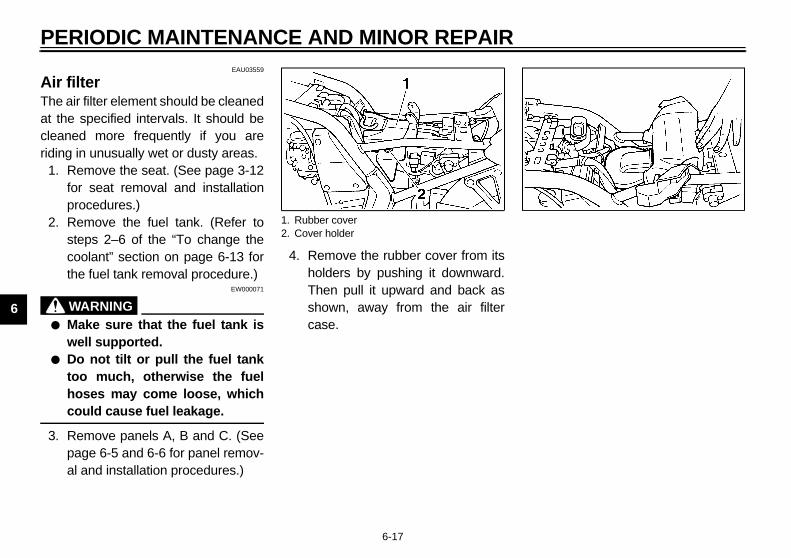
EAU03559
filter air filter element should be cleaned
the specified intervals. It should beaned more frequently if you areng in unusually wet or dusty areas.
Remove the seat. (See page 3-12for seat removal and installationprocedures.)Remove the fuel tank. (Refer tosteps 2–6 of the “To change thecoolant” section on page 6-13 forthe fuel tank removal procedure.)
EW000071
WARNINGMake sure that the fuel tank iswell supported.Do not tilt or pull the fuel tanktoo much, otherwise the fuelhoses may come loose, whichcould cause fuel leakage.
Remove panels A, B and C. (Seepage 6-5 and 6-6 for panel remov-al and installation procedures.)
4. Remove the rubber cover from itsholders by pushing it downward.Then pull it upward and back asshown, away from the air filtercase.
1. Rubber cover2. Cover holder

AND MINOR REPAIR
6
5. Tap the air filter element lightly to
remove most of the dust and dirt.Blow out the remaining dirt withcompressed air from the meshside of the air filter element. If it isdamaged, replace it.
. Install by reversing the removalprocedure.
EC000085
AUTION:● Make sure the air filter is prop-
erly seated in the filter case.● The engine should never be run
without the air filter installed.Excessive piston and/or cylin-der wear may result.
1.2.
Air filter element
E_5dm.book Page 18 Thursday, August 17, 2000 12:08 PM
PERIODIC MAINTENANCE
6-18
. Remove the screws holding the airfilter case cover.
6. Pull out the air filter element. 7
8
C@
@
Air filter case coverScrew (× 4)
1. Air filter element 1.
PE
6
@
●
●
@
EAU00632
justing the engine idling ed engine idling speed must becked and, if necessary, adjusted asws at the intervals specified in the
iodic maintenance and lubricationrt.Start the engine and warm it up forseveral minutes at 1,000–2,000 r/min while occasionally rev-ving it to 4,000–5,000 r/min.
TE: engine is warm when it quickly re-nds to the throttle.
E_5dm.book Page 19 Thursday, August 17, 2000 12:08 PM
RIODIC MAINTENANCE AND MINOR REPAIR
6-19
EW000072
WARNINGBefore installing the fuel tank,make sure that the fuel hosesare not damaged. If any fuelhose is damaged, do not startthe engine but have a Yamahadealer replace the hose, other-wise fuel may leak.Make sure that the fuel hosesare properly connected androuted, and not pinched.
EAU00630
Adjusting the carburetors The carburetors are important parts ofthe engine and require very sophisti-cated adjustment. Therefore, most car-buretor adjustments should be left to aYamaha dealer, who has the neces-sary professional knowledge and expe-rience. The adjustment described inthe following section, however, may beserviced by the owner as part of routinemaintenance.
EC000095
CAUTION:@
The carburetors have been set andextensively tested at the Yamahafactory. Changing these settingswithout sufficient technical knowl-edge may result in poor perfor-mance of or damage to the engine. @
AdspeThechefollopercha
1.
NO@
Thespo@

AND MINOR REPAIR
6
2
N@
If obYa@
EAU00637
djusting the valve clearance e valve clearance changes with use,
sulting in improper air-fuel mixtured/or engine noise. To prevent thism occurring, the valve clearance
ust be adjusted by a Yamaha dealer the intervals specified in the periodicaintenance and lubrication chart.
1.
E_5dm.book Page 20 Thursday, August 17, 2000 12:08 PM
PERIODIC MAINTENANCE
6-20
. Check the engine idling speedand, if necessary, adjust it to spec-ification by turning the throttle stopscrew. To increase the engineidling speed, turn the screw in di-rection a. To decrease the engineidling speed, turn the screw in di-rection b.
OTE:the specified idling speed cannot betained as described above, have amaha dealer make the adjustment.
EAU00635
Adjusting the throttle cable free play The throttle cable free play shouldmeasure 3–5 mm at the throttle grip.Periodically check the throttle cablefree play and, if necessary, have aYamaha dealer adjust it.
AThreanfromatm
Throttle stop screw
Engine idling speed:1,150–1,250 r/min
a. Throttle cable free play

PE
6
TirTo ity,cycreg
TireThechebef
@
●
●
@
EWA00012
WARNINGause loading has an enormousact on the handling, braking,formance and safety characteris- of your motorcycle, you shouldp the following precautions ind. NEVER OVERLOAD THEMOTORCYCLE! Operation of anoverloaded motorcycle may re-sult in tire damage, loss of con-trol, or severe injury. Make surethat the total weight of rider,passenger, cargo, and accesso-ries does not exceed the speci-fied maximum load for thevehicle. Do not carry along looselypacked items, which can shiftduring a ride. Securely pack the heaviestitems close to the center of themotorcycle and distribute theweight evenly on both sides.
E_5dm.book Page 21 Thursday, August 17, 2000 12:08 PM
RIODIC MAINTENANCE AND MINOR REPAIR
6-21
EAU00658
es maximize the performance, durabil- and safe operation of your motor-le, note the following pointsarding the specified tires.
air pressure tire air pressure should becked and, if necessary, adjustedore each ride.
EW000082
WARNINGThe tire air pressure must bechecked and adjusted on coldtires (i.e., when the temperatureof the tires equals the ambienttemperature). The tire air pressure must beadjusted in accordance with theriding speed and with the totalweight of rider, passenger, car-go, and accessories approvedfor this model.
CE-01E
CE-07E
@
Becimpperticskeemin
●
●
●
Tire air pressure(measured on cold tires)
Load* Front Rear
Up to 90 kg225 kPa2.25 kg/cm2
2.25 bar
250 kPa2.50 kg/cm2
2.50 bar
90 kg–maximum225 kPa2.25 kg/cm2
2.25 bar
290 kPa2.90 kg/cm2
2.90 bar
High-speed riding225 kPa2.25 kg/cm2
2.25 bar
290 kPa2.90 kg/cm2
2.90 bar
Maximum load* 187 kg
* Total weight of rider, passenger, cargo andaccessories

AND MINOR REPAIR
6
@
EW000079
WARNING● Have a Yamaha dealer replace
excessively worn tires. Besidesbeing illegal, operating themotorcycle with excessivelyworn tires decreases riding sta-bility and can lead to loss ofcontrol.
● The replacement of all wheel-and brake-related parts, includ-ing the tires, should be left to aYamaha dealer, who has thenecessary professional knowl-edge and experience.
E_5dm.book Page 22 Thursday, August 17, 2000 12:08 PM
PERIODIC MAINTENANCE
6-22
● Adjust the suspension and tireair pressure with regard to theload.
● Check the tire condition and airpressure before each ride.
Tire inspectionThe tires must be checked before eachride. If the center tread depth reachesthe specified limit, if the tire has a nailor glass fragments in it, or if the side-wall is cracked, have a Yamaha dealerreplace the tire immediately.CE-08E
NOTE:@
The tire tread depth limits may differfrom country to country. Always complywith the local regulations. @
@
@
1. Side walla. Tire tread depth
Minimum tire tread depth (front and rear)
1.6 mm

PE
6
TireThiwh
E
E
1. T2. V3. V
NT
nufacturer Size Type
idgestone 110/70 ZR17 (54W) BT-57F
nlop 110/70 ZR17 (54W) D207F
R
nufacturer Size Type
idgestone 160/60 ZR17 (69W) BT-57R
nlop 160/60 ZR17 (69W) D207J
FRONT & REAR
Tire air valve TR412
Valve core #9000A (original)
E_5dm.book Page 23 Thursday, August 17, 2000 12:08 PM
RIODIC MAINTENANCE AND MINOR REPAIR
6-23
informations motorcycle is equipped with casteels and tubeless tires with valves.
EW000080
WARNING@
● The front and rear tires shouldbe of the same make and de-sign, otherwise the handlingcharacteristics of the motor-cycle cannot be guaranteed.
● After extensive tests, only thetires listed below have been ap-proved for this model byYamaha Motor Co., Ltd.
● Always make sure that the valvecaps are securely installed toprevent air pressure leakage.
● Use only the tire valves andvalve cores listed below toavoid tire deflation during ahigh-speed ride.
@
CE-10
CE-14
ire air valvealve corealve cap with seal
FRO
Ma
Br
Du
REA
Ma
Br
Du

AND MINOR REPAIR
6
@
Thhipofic
@
EAU00692
djusting the clutch lever free ay e clutch lever free play should mea-re 10–15 mm as shown. Periodicallyeck the clutch lever free play and, ifcessary, adjust it as follows.. Loosen the locknut at the clutch le-
ver.. To increase the clutch lever free
play, turn the adjusting bolt in di-rection a. To decrease the clutchlever free play, turn the adjustingbolt in direction b.
. Tighten the locknut.
Clutch lever free play locknutClutch lever free play adjusting boltClutch lever free play
E_5dm.book Page 24 Thursday, August 17, 2000 12:08 PM
PERIODIC MAINTENANCE
6-24
EAU00684
WARNINGis motorcycle is fitted with super-
gh-speed tires. Note the followingints in order to make the most ef-ient use of these tires.● Use only the specified replace-
ment tires. Other tires may runthe danger of bursting at superhigh speeds.
● Brand-new tires can have a rela-tively poor grip on certain roadsurfaces until they have been“broken in”. Therefore, it is ad-visable before doing any high-speed riding to ride conserva-tively for approximately 100 kmafter installing a new tire.
● The tires must be warmed upbefore a high-speed run.
● Always adjust the tire air pres-sure according to the operatingconditions.
EAU00687
Wheels To maximize the performance, durabil-ity, and safe operation of your motor-cycle, note the following pointsregarding the specified wheels.
● The wheel rims should be checkedfor cracks, bends or warpage be-fore each ride. If any damage isfound, have a Yamaha dealer re-place the wheel. Do not attempteven the smallest repair to thewheel. A deformed or crackedwheel must be replaced.
● The wheel should be balancedwhenever either the tire or wheelhas been changed or replaced. Anunbalanced wheel can result inpoor performance, adverse han-dling characteristics, and a short-ened tire life.
● Ride at moderate speeds afterchanging a tire since the tire sur-face must first be “broken in” for it todevelop its optimal characteristics.
AplThsuchne
1
2
3
1.2.c.

PE
6
NO@
If thtainclua Yclu@
EW000109
WARNINGoft or spongy feeling in the brakeal can indicate the presence ofin the hydraulic system. If thereir in the hydraulic system, have aaha dealer bleed the system be-
operating the motorcycle. Air in hydraulic system will diminish braking performance, whichy result in loss of control and anident.
E_5dm.book Page 25 Thursday, August 17, 2000 12:08 PM
RIODIC MAINTENANCE AND MINOR REPAIR
6-25
TE:e specified free play cannot be ob-ed as described above or if the
tch does not operate correctly, haveamaha dealer check the internal
tch mechanism.
EAU00712
Adjusting the brake pedal position The top of the brake pedal should bepositioned approximately 36.6 mm be-low the top of the footrest as shown.Periodically check the brake pedal po-sition and, if necessary, have aYamaha dealer adjust it.
@
A spedair is aYamforethethemaacc@
a. Distance between brake pedal and footrest

AND MINOR REPAIR
6
AswThtivadonneasTuremtumtu
1.2.
Brake pad wear indicator groove
E_5dm.book Page 26 Thursday, August 17, 2000 12:08 PM
PERIODIC MAINTENANCE
6-26
EAU00713
djusting the rear brake light itch
e rear brake light switch, which is ac-ated by the brake pedal, is properlyjusted when the brake light comes just before braking takes effect. Ifcessary, adjust the brake light switch follows.rn the adjusting nut while holding the
ar brake light switch in place. Toake the brake light come on earlier,rn the adjusting nut in direction a. Toake the brake light come on later,rn the adjusting nut in direction b.
EAU01314
Checking the front and rear brake pads The front and rear brake pads must bechecked for wear at the intervals spec-ified in the periodic maintenance andlubrication chart. Each brake pad isprovided with a wear indicator groove,which allows you to check the brakepad wear without having to disassem-ble the brake. To check the brake padwear, check the wear indicatorgrooves. If a brake pad has worn to thepoint that the wear indicator groove hasalmost disappeared, have a Yamahadealer replace the brake pads as a set.
Rear brake light switchBrake light switch adjusting nut
1. Brake pad wear indicator groove 1.

PE
6
ChInsentingBeis arepid landbrabratem
Be careful that water does not en-ter the master cylinder when refill-ing. Water will significantly lowerthe boiling point of the fluid andmay result in vapor lock.Brake fluid may deteriorate paint-ed surfaces or plastic parts. Al-ways clean up spilled fluidimmediately.As the brake pads wear, it is nor-mal for the brake fluid level togradually go down. However, if thebrake fluid level goes down sud-denly, have a Yamaha dealercheck the cause.
1. M
F
E_5dm.book Page 27 Thursday, August 17, 2000 12:08 PM
RIODIC MAINTENANCE AND MINOR REPAIR
6-27
EAU03196
ecking the brake fluid level ufficient brake fluid may allow air toer the brake system, possibly caus- it to become ineffective.fore riding, check that the brake fluidbove the minimum level mark andlenish if necessary. A low brake flu-evel may indicate worn brake pads/or brake system leakage. If theke level is low, be sure to check theke pads for wear and the brake sys- for leakage.
Observe these precautions:● When checking the fluid level,
make sure that the top of the mas-ter cylinder or brake fluid reservoiris level.
● Use only the recommended quali-ty brake fluid, otherwise the rubberseals may deteriorate, causingleakage and poor braking perfor-mance.
● Refill with the same type of brakefluid. Mixing fluids may result in aharmful chemical reaction andlead to poor braking performance.
●
●
●inimum level mark
ront brake
1. Minimum level mark
Recommended brake fluid: DOT 4
Rear brake

AND MINOR REPAIR
6
CHbrthtioofasthth
. If the drive chain slack is incorrect,adjust it as follows.
Drive chain slack:30–45 mm
E_5dm.book Page 28 Thursday, August 17, 2000 12:08 PM
PERIODIC MAINTENANCE
6-28
EAU03238
hanging the brake fluid ave a Yamaha dealer change theake fluid at the intervals specified ine periodic maintenance and lubrica-n chart. In addition, have the oil seals the brake master cylinder and caliper well as the brake hose replaced ate intervals listed below or wheneverey are damaged or leaking.● Oil seals: Replace every two
years.● Brake hose: Replace every four
years.
EAU00745
Drive chain slack The drive chain slack should bechecked before each ride and adjustedif necessary.
To check the drive chain slack 1. Place the motorcycle on the cen-
terstand.2. Shift the transmission into the neu-
tral position.3. Spin the rear wheel several times
to locate the tightest portion of thedrive chain.
4. Measure the drive chain slack asshown.
5
a. Drive chain slack

PE
6To
1.
2.
EAU03006
bricating the drive chain drive chain must be cleaned and
ricated at the intervals specified in periodic maintenance and lubrica- chart, otherwise it will quickly wear, especially when riding in dusty or areas. Service the drive chain asws.
EC000097
UTION: drive chain must be lubricatedr washing the motorcycle or
ng in the rain.
Clean the drive chain with kero-sene and a small soft brush.
ECA00053
UTION:prevent damaging the O-rings,not clean the drive chain with
am cleaners, high-pressurehers or inappropriate solvents.
1. A2. D3. C4. A
E_5dm.book Page 29 Thursday, August 17, 2000 12:08 PM
RIODIC MAINTENANCE AND MINOR REPAIR
6-29
EAU00762
adjust the drive chain slack Loosen the axle nut, then thechain puller locknut at each end ofthe swingarm.To tighten the drive chain, turn theadjusting nut at each end of theswingarm in direction a. To loos-en the drive chain, turn the adjust-ing nut at each end of theswingarm in direction b, and thenpush the rear wheel forward.
NOTE:@
Using the alignment marks on eachside of the swingarm, make sure thatboth adjusting nuts are in the same po-sition for proper wheel alignment. @
EC000096
CAUTION:@
Improper drive chain slack will over-load the engine as well as other vitalparts of the motorcycle and can leadto chain slippage or breakage. Toprevent this from occurring, keepthe drive chain slack within thespecified limits. @
3. Tighten the locknuts, and thentighten the axle nut to the specifiedtorque.
LuThelubthetionoutwetfollo
CA@
Theafteridi@
1.
CA@
To do stewas@
xle nutrive chain slack adjusting nuthain puller locknutlignment marks
Tightening torque:Axle nut:
117 Nm (11.7 m·kg)

AND MINOR REPAIR
6
23
C@
Dluthco@
E_5dm.book Page 30 Thursday, August 17, 2000 12:08 PM
PERIODIC MAINTENANCE
6-30
. Wipe the drive chain dry.
. Thoroughly lubricate the drivechain with a special O-ring chainlubricant.
ECA00052
AUTION:o not use engine oil or any otherbricants for the drive chain, asey may contain substances thatuld damage the O-rings.
EAU02962
Checking and lubricating the cables The operation of all control cables andthe condition of the cables should bechecked before each ride, and the ca-bles and cable ends should be lubricat-ed if necessary. If a cable is damagedor does not move smoothly, have aYamaha dealer check or replace it.
EW000112
WARNING@
Damage to the outer sheath may in-terfere with proper cable operationand will cause the inner cable torust. Replace a damaged cable assoon as possible to prevent unsafeconditions. @
Recommended lubricant:Engine oil

PE
6
ChthrThetheshoandrep
NO@
Sinto throwa@
1.
2.
3.
4.
EAU03370
ecking and lubricating the ke and shift pedals operation of the brake and shiftals should be checked before each, and the pedal pivots should be lu-ated if necessary.
ecommended lubricant:Lithium-soap-based grease (all-purpose grease)
E_5dm.book Page 31 Thursday, August 17, 2000 12:08 PM
RIODIC MAINTENANCE AND MINOR REPAIR
6-31
EAU03209
ecking and lubricating the ottle grip and cable operation of the throttle grip and
condition of the throttle cableuld be checked before each ride, the cable should be lubricated orlaced if necessary.
TE:ce the throttle grip must be removedaccess the throttle cable end, thettle grip and the cable should al-
ys be lubricated at the same time.
Remove the throttle grip by remov-ing the screws.Disconnect the throttle cable, holdit up, and then apply several dropsof oil to the cable end, allowing it totrickle into the sheath.Connect the throttle cable, andthen grease the inside of the throt-tle grip housing.Grease the metal-to-metal contactsurface of the throttle grip, andthen install the grip by installingthe screws.
ChbraThepedridebric
Recommended lubricant:Throttle cable:
Engine oilThrottle grip housing and grip:
Lithium-soap-based grease (all-purpose grease)
R

AND MINOR REPAIR
6
CbrThleridbr
Recommended lubricant:Lithium-soap-based grease (all-purpose grease)
E_5dm.book Page 32 Thursday, August 17, 2000 12:08 PM
PERIODIC MAINTENANCE
6-32
EAU03164
hecking and lubricating the ake and clutch levers e operation of the brake and clutch
vers should be checked before eache, and the lever pivots should be lu-icated if necessary.
EAU03371
Checking and lubricating the centerstand and sidestand The operation of the centerstand andsidestand should be checked beforeeach ride, and the pivots and metal-to-metal contact surfaces should be lubri-cated if necessary.
EW000114
WARNING@
If the centerstand or sidestand doesnot move up and down smoothly,have a Yamaha dealer check or re-pair it. @
Recommended lubricant:Lithium-soap-based grease (all-purpose grease)

PE
6
LusuThesiospeand
check the operationPlace the motorcycle on a levelsurface and hold it in an uprightposition.While applying the front brake,push down hard on the handle-bars several times to check if thefront fork compresses and re-bounds smoothly.
EC000098
UTION:ny damage is found or the front does not operate smoothly,e a Yamaha dealer check or re-r it.
R
E_5dm.book Page 33 Thursday, August 17, 2000 12:08 PM
RIODIC MAINTENANCE AND MINOR REPAIR
6-33
EAU00790
bricating the rear spension pivoting points of the rear suspen-
n must be lubricated at the intervalscified in the periodic maintenance lubrication chart.
EAU02939
Checking the front fork The condition and operation of the frontfork must be checked as follows at theintervals specified in the periodic main-tenance and lubrication chart.
To check the conditionEW000115
WARNING@
Securely support the motorcycle sothat there is no danger of it fallingover. @
Check the inner tubes for scratches,damage and excessive oil leakage.
To 1.
2.
CA@
If aforkhavpai@
ecommended lubricant:Molybdenum disulfide grease

AND MINOR REPAIR
6
CWcaoflorioch
1
@
Sethov@
EAU01144
hecking the wheel bearings e front and rear wheel bearings must checked at the intervals specified in
e periodic maintenance and lubrica-n chart. If there is play in the wheelb or if the wheel does not turnoothly, have a Yamaha dealereck the wheel bearings.
E_5dm.book Page 34 Thursday, August 17, 2000 12:08 PM
PERIODIC MAINTENANCE
6-34
EAU00794
hecking the steering orn or loose steering bearings mayuse danger. Therefore, the operation the steering must be checked as fol-ws at the intervals specified in the pe-dic maintenance and lubricationart.. Place a stand under the engine to
raise the front wheel off theground.
EW000115
WARNINGcurely support the motorcycle so
at there is no danger of it fallinger.
2. Hold the lower ends of the frontfork legs and try to move them for-ward and backward. If any freeplay can be felt, have a Yamahadealer check or repair the steer-ing.
CThbethtiohusmch

PE
6
BaThiseanotno add
To Hateryhavbatif thtion
@
●
store the battery. If the motorcycle will not be used
for more than one month, removethe battery, fully charge it, andthen place it in a cool, dry place.
. If the battery will be stored formore than two months, check it atleast once a month and fullycharge it if necessary.
. Fully charge the battery before in-stallation.
EC000102
UTION:Always keep the batterycharged. Storing a dischargedbattery can cause permanentbattery damage.To charge a sealed-type (MF)battery, a special (constant-voltage) battery charger is re-quired. Using a conventionalbattery charger will damage thebattery. If you do not have ac-cess to a sealed-type (MF) bat-tery charger, have a Yamahadealer charge your battery.
E_5dm.book Page 35 Thursday, August 17, 2000 12:08 PM
RIODIC MAINTENANCE AND MINOR REPAIR
6-35
EAU01271
ttery s motorcycle is equipped with aled-type (MF) battery, which does require any maintenance. There isneed to check the electrolyte or to distilled water.
charge the batteryve a Yamaha dealer charge the bat- as soon as possible if it seems toe discharged. Keep in mind that thetery tends to discharge more quicklye motorcycle is equipped with op-al electrical accessories.
EW000116
WARNINGElectrolyte is poisonous anddangerous since it contains sul-furic acid, which causes severeburns. Avoid any contact withskin, eyes or clothing and al-ways shield your eyes whenworking near batteries. In caseof contact, administer the fol-lowing FIRST AID.
• EXTERNAL: Flush with plentyof water.
• INTERNAL: Drink large quan-tities of water or milk and im-mediately call a physician.
• EYES: Flush with water for15 minutes and seek promptmedical attention.
● Batteries produce explosive hy-drogen gas. Therefore, keepsparks, flames, cigarettes, etc.,away from the battery and pro-vide sufficient ventilation whencharging it in an enclosedspace.
● KEEP THIS AND ALL BATTER-IES OUT OF THE REACH OFCHILDREN.
@
To1
2
3
CA@
●
●
@

AND MINOR REPAIR
6
RThseanIf
1
2
1.2.3.4.5.6.7.8.
E_5dm.book Page 36 Thursday, August 17, 2000 12:08 PM
PERIODIC MAINTENANCE
6-36
EAU01720*
eplacing the fuses e fuse boxes are located under theat. (See page 3-12 for seat removald installation procedures.)
a fuse is blown, replace it as follows.. Turn the key to “OFF” and turn off
the electrical circuit in question.. Remove the blown fuse, and then
install a new fuse of the specifiedamperage.
EC000103
CAUTION:@
Do not use a fuse of a higher amper-age rating than recommended toavoid causing extensive damage tothe electrical system and possibly afire. @
3. Turn the key to “ON” and turn onthe electrical circuit in question tocheck if the device operates.
4. If the fuse immediately blowsagain, have a Yamaha dealercheck the electrical system.
Main fuseSpare fuse (× 4)Ignition fuseSignaling system fuseHeadlight fuseRadiator fan fuseOdometer fuseHazard fuse
Specified fuses:Main fuse: 30 AHeadlight fuse: 20 AHazard fuse: 10 AIgnition fuse: 20 ASignaling system fuse: 20 AOdometer fuse: 5 ARadiator fan fuse: 10 A

PE
6
ReThiquabul
1.
EW000119
WARNINGdlight bulbs get very hot. There-, keep flammable products away a lit headlight bulb, and do not
ch the bulb until it has cooledn.
Place a new bulb into position, andthen secure it with the bulb holder.
1. H2. H
o not touch this area.
E_5dm.book Page 37 Thursday, August 17, 2000 12:08 PM
RIODIC MAINTENANCE AND MINOR REPAIR
6-37
EAU00826
placing the headlight bulb s motorcycle is equipped with artz bulb headlight. If the headlight
b burns out, replace it as follows.Disconnect the headlight coupler,and then remove the headlightbulb cover.
2. Unhook the headlight bulb holder,and then remove the defectivebulb.
@
Heaforefromtoudow@
3.
eadlight bulb covereadlight coupler
1. Headlight bulb holder 1. D

AND MINOR REPAIR
6
C@
Tain
Dheoithanfeanbual
@
4
5
. Install the socket (together withthe bulb) by turning it clockwise.
. Install the owner’s tool kit.
. Install the seat.
E_5dm.book Page 38 Thursday, August 17, 2000 12:08 PM
PERIODIC MAINTENANCE
6-38
EC000104
AUTION:ke care not to damage the follow-
g parts:● Headlight bulbo not touch the glass part of theadlight bulb to keep it free from
l, otherwise the transparency ofe glass, the luminosity of the bulb,d the bulb life will be adversely af-
cted. Thoroughly clean off any dirtd fingerprints on the headlightlb using a cloth moistened with
cohol or thinner.● Headlight lens
• Do not affix any type of tintedfilm or stickers to the head-light lens.
• Do not use a headlight bulb ofa wattage higher than speci-fied.
. Install the bulb cover, and thenconnect the coupler.
. Have a Yamaha dealer adjust theheadlight beam if necessary.
EAU00858
Replacing the tail/brake light bulb
1. Remove the seat. (See page 3-12for seat removal and installationprocedures.)
2. Remove the owner’s tool kit.3. Remove the socket (together with
the bulb) by turning it counter-clockwise.
4. Remove the defective bulb bypushing it in and turning it counter-clockwise.
5. Insert a new bulb into the socket,push it in, and then turn it clock-wise until it stops.
6
78
1. Socket
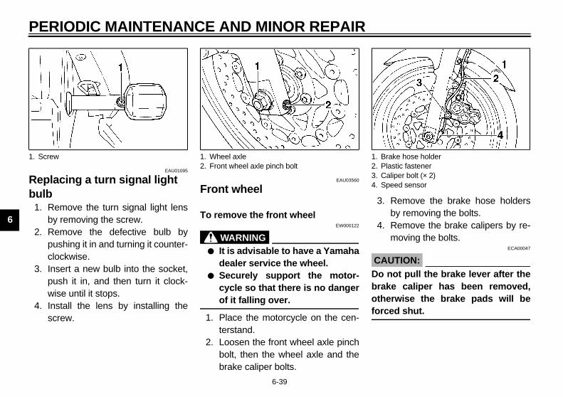
PE
6
Rebu
1.
2.
3.
4.
Remove the brake hose holdersby removing the bolts.Remove the brake calipers by re-moving the bolts.
ECA00047
UTION:not pull the brake lever after theke caliper has been removed,erwise the brake pads will beed shut.
1. S rake hose holderlastic fasteneraliper bolt (× 2)peed sensor
E_5dm.book Page 39 Thursday, August 17, 2000 12:08 PM
RIODIC MAINTENANCE AND MINOR REPAIR
6-39
EAU01095
placing a turn signal light lb
Remove the turn signal light lensby removing the screw.Remove the defective bulb bypushing it in and turning it counter-clockwise.Insert a new bulb into the socket,push it in, and then turn it clock-wise until it stops.Install the lens by installing thescrew.
EAU03560
Front wheel
To remove the front wheel EW000122
WARNING@
● It is advisable to have a Yamahadealer service the wheel.
● Securely support the motor-cycle so that there is no dangerof it falling over.
@
1. Place the motorcycle on the cen-terstand.
2. Loosen the front wheel axle pinchbolt, then the wheel axle and thebrake caliper bolts.
3.
4.
CA@
Do braothforc@
crew 1. Wheel axle2. Front wheel axle pinch bolt
1. B2. P3. C4. S

AND MINOR REPAIR
6
5
6
. Insert the wheel axle.
. Lower the front wheel so that it ison the ground.
. Push down hard on the handlebarseveral times to check for properfork operation.
. Install the brake calipers by install-ing the bolts.
TE:ake sure that there is enough spacetween the brake pads before install-
g the brake calipers onto the brakecs.
. Install the brake hose holders byinstalling the bolts.
Speed sensor retainer
E_5dm.book Page 40 Thursday, August 17, 2000 12:08 PM
PERIODIC MAINTENANCE
6-40
. Remove the plastic fastener hold-ing the speed sensor lead and thebrake hose together.
. While supporting the speed sen-sor, pull the wheel axle out, andthen remove the wheel.
EAU01309*
To install the front wheel 1. Lift the wheel up between the fork
legs.2. Install the speed sensor at the
wheel hub.
NOTE:@
Make sure that the projections on thespeed sensor rotor are aligned with thenotches in the wheel hub and that theslot in the speedsensor fits over the re-tainer on the fork leg. @
34
5
6
NO@
Mbeindis@
7
1. Speed sensor 1.

PE
6
8.
9.
Disconnect the brake torque rodfrom the brake caliper bracket byremoving the nut and the bolt.Place the motorcycle on the cen-terstand.Remove the axle nut and thebrake caliper by removing thebolts.Loosen the locknut and drivechain adjusting nut on each side ofthe swingarm.Push the wheel forward, and thenremove the drive chain from therear sprocket.
Tke caliper bolt (× 2)ke torque rodke torque rod nutke caliper bracket
E_5dm.book Page 41 Thursday, August 17, 2000 12:08 PM
RIODIC MAINTENANCE AND MINOR REPAIR
6-41
Bind the speed sensor lead andthe brake hose together with theplastic fastener.Tighten the wheel axle, frontwheel axle pinch bolt and brakecaliper bolts to the specifiedtorques.
EAU01318*
Rear wheel
To remove the rear wheel EW000122
WARNING@
● It is advisable to have a Yamahadealer service the wheel.
● Securely support the motor-cycle so that there is no dangerof it falling over.
@
1. Loosen the axle nut and the brakecaliper bolts.
2.
3.
4.
5.
6.
ightening torques:Wheel axle:
67 Nm (6.7 m·kg)Front wheel axle pinch bolt:
20 Nm (2.0 m·kg)Brake caliper bolt:
40 Nm (4.0 m·kg)
1. Axle nut2. Drive chain slack adjusting nut3. Locknut
1. Bra2. Bra3. Bra4. Bra
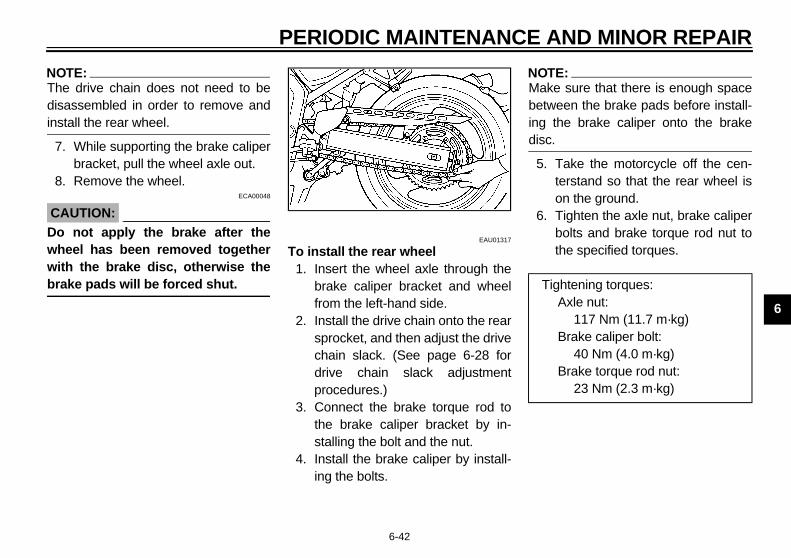
AND MINOR REPAIR
6
N@
Thdiin@
7
8
C@
Dwwbr@
TE:ake sure that there is enough spacetween the brake pads before install- the brake caliper onto the brakec.
. Take the motorcycle off the cen-terstand so that the rear wheel ison the ground.
. Tighten the axle nut, brake caliperbolts and brake torque rod nut tothe specified torques.
Tightening torques:Axle nut:
117 Nm (11.7 m·kg)Brake caliper bolt:
40 Nm (4.0 m·kg)Brake torque rod nut:
23 Nm (2.3 m·kg)
E_5dm.book Page 42 Thursday, August 17, 2000 12:08 PM
PERIODIC MAINTENANCE
6-42
OTE:e drive chain does not need to be
sassembled in order to remove andstall the rear wheel.
. While supporting the brake caliperbracket, pull the wheel axle out.
. Remove the wheel.ECA00048
AUTION:o not apply the brake after theheel has been removed togetherith the brake disc, otherwise theake pads will be forced shut.
EAU01317
To install the rear wheel 1. Insert the wheel axle through the
brake caliper bracket and wheelfrom the left-hand side.
2. Install the drive chain onto the rearsprocket, and then adjust the drivechain slack. (See page 6-28 fordrive chain slack adjustmentprocedures.)
3. Connect the brake torque rod tothe brake caliper bracket by in-stalling the bolt and the nut.
4. Install the brake caliper by install-ing the bolts.
NO@
Mbeingdis@
5
6

PE
6
TroAltha thfromingcomexalosTherepfor selreqdeatheknoproUsmelikeinfecan
E_5dm.book Page 43 Thursday, August 17, 2000 12:08 PM
RIODIC MAINTENANCE AND MINOR REPAIR
6-43
EAU03087
ubleshooting ough Yamaha motorcycles receiveorough inspection before shipment the factory, trouble may occur dur-
operation. Any problem in the fuel,pression, or ignition systems, formple, can cause poor starting and
s of power. following troubleshooting charts
resent quick and easy procedureschecking these vital systems your-f. However, should your motorcycleuire any repair, take it to a Yamahaler, whose skilled technicians have
necessary tools, experience, andw-how to service the motorcycleperly.e only genuine Yamaha replace-nt parts. Imitation parts may look Yamaha parts, but they are oftenrior, have a shorter service life and lead to expensive repair bills.

AND MINOR REPAIR
6
EAU02990
TroubleshootingStarting problems o
EW000125
WARNING@
Keep away open fla . @
1. Fuel
o to compression check.
Engine doesn’t start, ask a Yamaha dealer to inspect.
Engine doesn’t start, go to battery check.
Open throttle half-way and startthe engine.
E_5dm.book Page 44 Thursday, August 17, 2000 12:08 PM
Check if there is fuin the fuel tank.
Use the electric sta
2. Compres
Remove spark plugand check electrod
3. Ignition
Use the electric sta
4. Battery
PERIODIC MAINTENANCE
6-44
charts r poor engine performance
mes and do not smoke while checking or working on the fuel system
el Enough fuel.
No fuel.
Go to compression check.
Supply fuel. Engine doesn’t start, g
rter.
sionThere is compression.
No compression.
Go to ignition check.
Ask a Yamaha dealer to inspect.
ses.
Wet.
Dry.
Wipe clean with dry cloth and correct spark gap or replace spark plugs.
Ask a Yamaha dealer to inspect.
rter.
Engine turns over quickly.
Engine turns over slowly.
Battery good.
Check connections orrecharge.

PE
6
EnEW000070
@
● hot fluid and steam may bee engine has cooled.
● the radiator cap, and then to escape. When the hiss-nd then remove the cap.
@
NO@
If c anged to the recommended coolantas @
e.
ge.Ask a Yamaha dealer to inspect and repair the cooling system.
Add coolant. (See NOTE.)
. If the engine overheats again, ask a inspect and repair the cooling system.
E_5dm.book Page 45 Thursday, August 17, 2000 12:08 PM
RIODIC MAINTENANCE AND MINOR REPAIR
6-45
gine overheating
WARNINGDo not remove the radiator cap when the engine and radiator are hot. Scalding blown out under pressure, which could cause serious injury. Be sure to wait until thAfter removing the radiator cap retaining bolt, place a thick rag, like a towel, overslowly rotate the cap counterclockwise to the detent to allow any residual pressureing sound has stopped, press down on the cap while turning it counterclockwise, a
TE:oolant is not available, tap water can be temporarily used instead, provided that it is chsoon as possible.
Wait until the engine has cooled.
Check the coolant level in the reservoir tank and/or radiator.
Level is OK.
Level is low, check the cooling system for leakage.
No leakag
Leaka
Restart the engineYamaha dealer to

MOTORCYCLE CARE AND STORAGE
7
Care .................................................................................................. 7-1Storage .............................................................................................. 7-4
E_5dm.book Page 1 Thursday, August 17, 2000 12:08 PM

7
EAU03426
aningECA00010
UTION:
E_5dm.book Page 1 Thursday, August 17, 2000 12:08 PM
7-MO
CaWhreve
Avoid using strong acidic wheelcleaners, especially on spokedwheels. If such products areused on hard-to-remove dirt, donot leave the cleaner on the af-fected area any longer than in-structed. Also, thoroughly rinsethe area off with water, immedi-ately dry it, and then apply acorrosion protection spray.Improper cleaning can damagewindshields, cowlings, panelsand other plastic parts. Useonly a soft, clean cloth orsponge with mild detergent andwater to clean plastic.
noloble.eveusenotifromtorcdoethe moand
7-1
TORCYCLE CARE AND STORAGE
re ile the open design of a motorcycleals the attractiveness of the tech-gy, it also makes it more vulnera- Rust and corrosion can developn if high-quality components ared. A rusty exhaust pipe may go un-ced on a car, however, it detracts the overall appearance of a mo-
ycle. Frequent and proper cares not only comply with the terms ofwarranty, but it will also keep your
torcycle looking good, extend its life optimize its performance.
Before cleaning1. Cover the muffler outlet with a
plastic bag after the engine hascooled down.
2. Make sure that all caps and coversas well as all electrical couplersand connectors, including thespark plug caps, are tightlyinstalled.
3. Remove extremely stubborn dirt,like oil burnt onto the crankcase,with a degreasing agent and abrush, but never apply such prod-ucts onto seals, gaskets, sprock-ets, the drive chain and wheelaxles. Always rinse the dirt anddegreaser off with water.
Cle
CA@
●
●

ARE AND STORAGE
7
ter riding in the rain, near the sea or salt-sprayed roadsnce sea salt or salt sprayed on roadsring winter are extremely corrosive inmbination with water, carry out thellowing steps after each ride in thein, near the sea or on salt-sprayedads.
TE:lt sprayed on roads in the winter may
main well into spring.
. Clean the motorcycle with coldwater and a mild detergent, afterthe engine has cooled down.
E_5dm.book Page 2 Thursday, August 17, 2000 12:08 PM
MOTORCYCLE C
7-2
● Do not use any harsh chemicalproducts on plastic parts. Besure to avoid using cloths orsponges which have been incontact with strong or abrasivecleaning products, solvent orthinner, fuel (gasoline), rust re-movers or inhibitors, brake flu-id, antifreeze or electrolyte.
● Do not use high-pressure wash-ers or steam-jet cleaners sincethey cause water seepage anddeterioration in the following ar-eas: seals (of wheel and swing-arm bearings, fork and brakes),electric components (couplers,connectors, instruments, switch-es and lights), breather hosesand vents.
● For motorcycles equipped witha windshield: Do not use strongcleaners or hard sponges asthey will cause dulling orscratching. Some cleaningcompounds for plastic mayleave scratches on the wind-shield. Test the product on asmall hidden part of the wind-shield to make sure that it doesnot leave any marks. If the wind-shield is scratched, use a quali-ty plastic polishing compoundafter washing.
@
After normal useRemove dirt with warm water, a milddetergent, and a soft, clean sponge,and then rinse thoroughly with cleanwater. Use a toothbrush or bottlebrushfor hard-to-reach areas. Stubborn dirtand insects will come off more easily ifthe area is covered with a wet cloth fora few minutes before cleaning.
AfonSiducoforaro
NO@
Sare@
1

M
7
CA@
Docresal@
2.
EWA00001
WARNINGMake sure that there is no oil orwax on the brakes or tires. Ifnecessary, clean the brakediscs and brake linings with aregular brake disc cleaner oracetone, and wash the tires withwarm water and a milddetergent.Before operating the motorcy-cle test its braking performanceand cornering behavior.
E_5dm.book Page 3 Thursday, August 17, 2000 12:08 PM
OTORCYCLE CARE AND STORAGE
7-3
ECA00012
UTION: not use warm water since it in-ases the corrosive action of thet.
Apply a corrosion protection sprayon all metal, including chrome-and nickel-plated, surfaces to pre-vent corrosion.
After cleaning1. Dry the motorcycle with a chamois
or an absorbing cloth.2. Immediately dry the drive chain
and lubricate it to prevent it fromrusting.
3. Use a chrome polish to shinechrome, aluminum and stainless-steel parts, including the exhaustsystem. (Even the thermally in-duced discoloring of stainless-steel exhaust systems can be re-moved through polishing.)
4. To prevent corrosion, it is recom-mended to apply a corrosion pro-tection spray on all metal,including chrome- and nickel-plat-ed, surfaces.
5. Use spray oil as a universal clean-er to remove any remaining dirt.
6. Touch up minor paint damagecaused by stones, etc.
7. Wax all painted surfaces.8. Let the motorcycle dry completely
before storing or covering it.
@
●
●
@

ARE AND STORAGE
7
C@
@
N@
Cw@
ng-termfore storing your motorcycle for sev-
al months:. Follow all the instructions in the
“Care” section of this chapter.. For motorcycles equipped with a
fuel cock that has an “OFF” posi-tion: Turn the fuel cock lever to“OFF”.
. Drain the carburetor float chamberby loosening the drain bolt; this willprevent fuel deposits from buildingup. Pour the drained fuel into thefuel tank.
. Fill up the fuel tank and add fuelstabilizer (if available) to preventthe fuel tank from rusting and thefuel from deteriorating.
. Perform the following steps to pro-tect the cylinders, piston rings, etc.from corrosion.
a. Remove the spark plug caps andspark plugs.
b. Pour a teaspoonful of engine oilinto each spark plug bore.
E_5dm.book Page 4 Thursday, August 17, 2000 12:08 PM
MOTORCYCLE C
7-4
ECA00013
AUTION:● Apply spray oil and wax spar-
ingly and make sure to wipe offany excess.
● Never apply oil or wax to anyrubber and plastic parts, buttreat them with a suitable careproduct.
● Avoid using abrasive polishingcompounds as they will wearaway the paint.
OTE:onsult a Yamaha dealer for advice onhat products to use.
Storage
Short-termAlways store your motorcycle in a cool,dry place and, if necessary, protect itagainst dust with a porous cover.
ECA00014
CAUTION:@
● Storing the motorcycle in apoorly ventilated room or cover-ing it with a tarp, while it is stillwet, will allow water and humid-ity to seep in and cause rust.
● To prevent corrosion, avoiddamp cellars, stables (becauseof the presence of ammonia)and areas where strong chemi-cals are stored.
@
LoBeer
1
2
3
4
5

M
7
c
d
e
@
To spaspathe@
6.
E_5dm.book Page 5 Thursday, August 17, 2000 12:08 PM
OTORCYCLE CARE AND STORAGE
7-5
. Install the spark plug caps onto thespark plugs, and then place thespark plugs on the cylinder headso that the electrodes are ground-ed. (This will limit sparking duringthe next step.)
. Turn the engine over several timeswith the starter. (This will coat thecylinder walls with oil.)
. Remove the spark plug caps fromthe spark plugs, and then installthe spark plugs and the spark plugcaps.
EWA00003
WARNINGprevent damage or injury fromrking, make sure to ground therk plug electrodes while turning engine over.
Lubricate all control cables andthe pivoting points of all levers andpedals as well as of the sidestand/centerstand.
7. Check and, if necessary, correctthe tire air pressure, and then liftthe motorcycle so that both of itswheels are off the ground. Alterna-tively, turn the wheels a little everymonth in order to prevent the tiresfrom becoming degraded in onespot.
8. Cover the muffler outlet with aplastic bag to prevent moisturefrom entering it.
9. Remove the battery and fullycharge it. Store it in a cool, dryplace and charge it once a month.Do not store the battery in an ex-cessively cold or warm place (lessthan 0 °C or more than 30 °C). Formore information on storing thebattery, see page 6-35.
NOTE:@
Make any necessary repairs beforestoring the motorcycle. @

SPECIFICATIONS
8
Specifications ..................................................................................... 8-1Conversion table ............................................................................... 8-5
E_5dm.book Page 1 Thursday, August 17, 2000 12:08 PM

8
EAU01038
E_5dm.book Page 1 Thursday, August 17, 2000 12:08 PM
8-SP
SpCS-01
M
oil API Service SE, SF, SG type or higher
ridge 2.5 L
e 2.7 L
gine) 3.5 L
-20 -10 0 10 20 30 40 50 ˚C
SAE 10W–30
SAE 15W–40
SAE 20W–40
SAE 20W–50
SAE 10W–40
or oils that do not contain anti-frictioner car motor oils (often labeled) contain anti-friction additives which/or starter clutch slippage, resulting inlife and poor engine performance.
D
Bf
E
8-1
ECIFICATIONS
ecificationsE
odel FZS600/FZS600SP
imensions
Overall length 2,080 mm (except for N, SF)
2,175 mm (for N, SF)
Overall width 710 mm
Overall height 1,170 mm
Seat height 790 mm
Wheelbase 1,415 mm
Ground clearance 130 mm
Minimum turning radius 2,900 mm
asic weight (with oil and full uel tank) 210 kg
ngine
Engine type Liquid-cooled 4-stroke, DOHC
Cylinder arrangement Forward-inclined parallel 4-cylinder
Displacement 599 cm3
Bore × Stroke 62.0 × 49.6 mm
Compression ratio 12:1
Starting system Electric starter
Lubrication system Wet sump
Engine oil
Type
Recommended engine classification
Quantity
Without oil filter cartreplacement
With oil filter cartridgreplacement
Total amount (dry en
CAUTION:
Be sure to use motmodifiers. Passeng“Energy Conserving”will cause clutch andreduced component

SPECIFICATIONS
8
ont) 48/15
Constant mesh 6-speed
Left foot
1st 2.846
2nd 1.947
3rd 1.545
4th 1.333
5th 1.190
6th 1.074
Double cradle
24°
88 mm
Tubeless
110 / 70 ZR17 (54W)
er/Bridgestone / BT-57F
Dunlop / D207F
E_5dm.book Page 2 Thursday, August 17, 2000 12:08 PM
8-2
Cooling system capacity (total amount)
1.95 L
Air filter Dry type element
Fuel
Type Regular unleaded gasoline
Fuel tank capacity 20 L
Fuel reserve amount 3.5 L
Carburetor
Manufacturer MIKUNI
Model × quantity BSR33 × 4
Spark plug
Manufacturer/type
Except for D, F NGK / CR8E, CR9E or DENSO / U24ESR-N, U27ESR-N
For D, F NGK / CR7E, CR8E, CR9E or DENSO / U22ESR-N, U24ESR-N, U27ESR-N
Gap 0.7–0.8 mm
Clutch type Wet, multiple-disc
Transmission
Primary reduction system Spur gear
Primary reduction ratio 1.708
Secondary reduction system Chain drive
Secondary reduction ratio 3.200
Number of drive chainsprocket teeth (rear/fr
Transmission type
Operation
Gear ratio
Chassis
Frame type
Caster angle
Trail
Tires
Front
Type
Size
Manufacturmodel

SP
8
Cast wheel
17 × MT 5.00
Dual disc brake
Right hand
DOT 4
Single disc brake
Right foot
DOT 4
Telescopic fork
Swingarm (link suspension)
Coil spring / oil damper
Coil spring / gas-oil damper
120 mm
120 mm
E_5dm.book Page 3 Thursday, August 17, 2000 12:08 PM
ECIFICATIONS
8-3
Rear
Type Tubeless
Size 160 / 60 ZR17 (69W)
Manufacturer/model Bridgestone / BT-57R
Dunlop / D207J
Maximum load* 187 kg
Tire air pressure (measured on cold tires)
Up to 90 kg*
Front 225 kPa (2.25 kg/cm2, 2.25 bar)
Rear 250 kPa (2.50 kg/cm2, 2.50 bar)
90 kg–maximum*
Front 225 kPa (2.25 kg/cm2, 2.25 bar)
Rear 290 kPa (2.90 kg/cm2, 2.90 bar)
High-speed riding
Front 225 kPa (2.25 kg/cm2, 2.25 bar)
Rear 290 kPa (2.90 kg/cm2, 2.90 bar)
* Total weight of rider, passenger, cargo and accessories.
Wheels
Front
Type Cast wheel
Size 17 × MT 3.00
Rear
Type
Size
Brakes
Front
Type
Operation
Fluid
Rear
Type
Operation
Fluid
Suspension
Front
Rear
Spring/shock absorber
Front
Rear
Wheel travel
Front
Rear

SPECIFICATIONS
8
30 A
20 A
20 A
20 A
10 A
10 A
5 A
E_5dm.book Page 4 Thursday, August 17, 2000 12:08 PM
8-4
Electrical system
Ignition system Transistorized coil ignition (digital)
Charging system
Model A.C. magneto
Standard output 14 V, 18 A @ 5,000 r/min
Battery
Model GT12B-4
Voltage, capacity 12 V, 10 Ah
Headlight type Quartz bulb (halogen)
Bulb voltage, wattage × quantity
Headlight 12 V, 60/55 W × 1
12 V, 55 W × 1
Auxiliary light 12 V, 5 W × 1
Tail/brake light 12 V, 5/21 W × 2
Turn signal light 12 V, 21 W × 4
Meter lighting 12 V, 2 W × 3
Neutral indicator light 14 V, 1.4 W × 1
High beam indicator light 14 V, 1.4 W × 1
Oil level warning light 14 V, 1.4 W × 1
Turn signal indicator light 14 V, 1.4 W × 2
Fuel level warning indicator light
12 V, 2 W × 1
Coolant temperature warning light LED
Fuses
Main fuse
Headlight fuse
Signaling system fuse
Ignition fuse
Radiator fan fuse
Hazard fuse
Odometer fuse

SP
8
CoCS-0
AllMEUsunEx
M
nversion tableRIC TO IMPERIAL
nit Multiplier Imperial unit
7.23386.7940.07230.8679
ft·lbin·lbft·lbin·lb
2.2050.03527
lboz
0.6214 mi/h
0.62143.2811.0940.39370.03937
miftydinin
0.035270.061020.87990.2199
oz (IMP liq.)cu·inqt (IMP liq.)gal (IMP liq.)
(°C)
55.99714.22349/5 + 32
lb/inpsi (lb/in2)Fahrenheit (°F)
E_5dm.book Page 5 Thursday, August 17, 2000 12:08 PM
ECIFICATIONS
8-5
EAU01064
nversion table 2E
specification data in this manual are listed in SI andTRIC UNITS. e this table to convert METRIC unit data to IMPERIALit data.ample
ETRIC MULTIPLIER IMPERIAL
** mm × 0.03937 = ** in
2 mm × 0.03937 = 0.08 in
CoMET
Metric u
Torque
m·kgm·kgcm·kgcm·kg
Weight kgg
Speed km/h
Distance
kmmmcmmm
Volume,Capacity
cc (cm3)cc (cm3)L (liter)L (liter)
Miscellaneouskg/mmkg/cm2
Centigrade

CONSUMER INFORMATION
9
Identification numbers ....................................................................... 9-1Key identification number .................................................................. 9-1Vehicle identification number ............................................................. 9-1Model label ........................................................................................ 9-2
E_5dm.book Page 1 Thursday, August 17, 2000 12:08 PM

9
EAU01039
E_5dm.book Page 1 Thursday, August 17, 2000 12:08 PM
9-CO
IdeRec
EAU01043
hicle identification number vehicle identification number is
mped into the steering head pipe.ord this number in the space
vided.
TE: vehicle identification number isd to identify your motorcycle andy be used to register your motorcy-with the licensing authority in youra.
ehicle identification number
vehel lavideorddeacle
1.CA-02
2.
CA-02
3.CA-01
9-1
NSUMER INFORMATIONEAU02944
ntification numbers ord the key identification number,icle identification number and mod-bel information in the spaces pro-d below for assistance when
ering spare parts from a Yamahaler or for reference in case the vehi-is stolen.
KEY IDENTIFICATION NUMBER:E
VEHICLE IDENTIFICATIONNUMBER:
E
MODEL LABEL INFORMATION:E
EAU01041
Key identification number The key identification number isstamped into the key tag. Record thisnumber in the space provided and useit for reference when ordering a newkey.
VeThestaRecpro
NO@
Theusemacle are@
1. Key identification number 1. V

MER INFORMATION
9
MThunpalatioThorde
1.
E_5dm.book Page 2 Thursday, August 17, 2000 12:08 PM
CONSU
9-2
EAU03171
odel label e model label is affixed to the frameder the passenger seat. (Seege 3-12 for seat removal and instal-
tion procedures.) Record the informa-n on this label in the space provided.is information will be needed whendering spare parts from a Yamahaaler.
Model label

D
fti-
ttaknaknakakakakakakak
brbrennttnoCCo
dentification numbers ..............................9-1dling speed, adjusting ...........................6-19gnition circuit cut-off system ..................3-16ndicator and warning lights......................3-3
ey identification number .........................9-1
ight switch ..............................................3-8uggage strap holders ...........................3-15
ain switch/steering lock .........................3-1aintenance and lubrication, periodic ......6-2odel label ..............................................9-2
eutral indicator light ...............................3-3
il level warning light ...............................3-3
anels, removing and installing................6-5arking.....................................................5-5art locations ...........................................2-1ass switch..............................................3-7re-operation check list............................4-1
E_5dm.book Page 1 Thursday, August 17, 2000 12:08 PM
10-IN
AAirAn
BBaBr
aBr
aBrBrBrBrBrBrBr
CCaCaCaCe
aCluCluCoCo
Co
e pedal..............................................3-9e pedal position, adjusting ..............6-25
les, checking and lubricating............6-30uretors, adjusting............................6-19.........................................................7-1
terstand and sidestand, checking d lubricating .....................................6-32ch lever..............................................3-8ch lever free play, adjusting .............6-24version table......................................8-5lant ..................................................6-12hanging..........................................6-13hecking ..........................................6-12
lant temperature warning light............3-3
Installing........................................... 6-40Removing......................................... 6-39
Fuel ....................................................... 3-11Fuel consumption, tips for reducing ......... 5-4Fuel gauge .............................................. 3-6Fuel level warning light ............................ 3-4Fuel tank breather hose......................... 3-11Fuel tank cap......................................... 3-10Fuse, replacing...................................... 6-36
HHandlebar switches ................................. 3-7Hazard switch.......................................... 3-7Headlight bulb, replacing ....................... 6-37Helmet holder ........................................ 3-13High beam indicator light ......................... 3-3Horn switch ............................................. 3-7
M
NN
OO
PPPPPP
EX
ilter ..................................................6-17theft alarm ........................................3-6
ery ...................................................6-35e and clutch levers, checking
d lubricating .....................................6-31e and shift pedals, checking
d lubricating .....................................6-31e fluid, changing .............................6-28e fluid level, checking......................6-27e lever...............................................3-9e light switch (rear), adjusting .........6-26e pads, checking.............................6-26
DDimmer switch......................................... 3-7Drive chain, lubricating .......................... 6-29Drive chain slack ................................... 6-28
Adjusting .......................................... 6-29Checking.......................................... 6-28
EEngine break-in ....................................... 5-4Engine oil and oil filter cartridge ............... 6-9Engine stop switch................................... 3-8
FFront fork, adjusting............................... 3-13Front fork, checking ............................... 6-33Front wheel ........................................... 6-39
IIIII
KK
LLL
MMM

INDEX
RRe
SSaSeSeShShShShSidSpSpSpStaStaStaStaSteStoStoSu
TTaTaTh
E_5dm.book Page 2 Thursday, August 17, 2000 12:08 PM
ecifications .......................................... 8-1eedometer unit .................................... 3-4rter (choke) lever .............................. 3-12rting a cold engine.............................. 5-1rting a warm engine............................ 5-3rt switch.............................................. 3-8ering, checking ................................. 6-33rage.................................................... 7-4rage compartment ............................ 3-13spension (rear), lubricating ................ 6-33
chometer ............................................. 3-5il/brake light bulb, replacing ............... 6-38rottle cable free play, adjusting .......... 6-20
Wheel bearings, checking ..................... 6-34Wheels.................................................. 6-24
ar wheel ............................................ 6-41Installing........................................... 6-42Removing......................................... 6-41
fety information..................................... 1-1at....................................................... 3-12lf-diagnosis device............................... 3-5ifting .................................................... 5-3ift pedal ............................................... 3-9ift points (for Switzerland only)............. 5-4ock absorber assembly, adjusting ..... 3-14estand .............................................. 3-15ark plugs, checking ............................. 6-7
Throttle grip and cable, checking and lubricating .................................... 6-31
Tires...................................................... 6-21Tool kit .................................................... 6-1Troubleshooting .................................... 6-43Troubleshooting charts.......................... 6-44Turn signal indicator lights....................... 3-3Turn signal light bulb, replacing............. 6-39Turn signal switch ................................... 3-7
VValve clearance, adjusting .................... 6-20Vehicle identification number................... 9-1
W

H_5KS_Toc0.fm Page 2 Monday, August 21, 2000 1
1:11 AM
5DM-28199-E4PRINTED IN JAPAN2000 · 5 - 0.5 × 3 CR
(E)
PRINTED ON RECYCLED PAPER
YAMAHA MOTOR CO., LTD.
FZS600FZS600SP
OWNER’S MANUAL