fusing vision-based bearing measurements and motion...
TRANSCRIPT
Fusing vision-based bearing measurements andmotion to localize pairs of robots
Luis Montesano1 Jose Gaspar21I3A, Dpto. de Informatica e Ing. de Sistemas
Universidad de ZaragozaZaragoza, Spain
{montesano,montano}@unizar.es
Jose Santos-Victor2 Luis Montano12Instituto de Sistemas e Robotica,
Instituto Superior TecnicoLisboa, Portugal
{jag,jasv}@isr.ist.utl.pt
Abstract— This paper presents a method to cooperativelylocalize pairs of robots fusing bearing-only information pro-vided by a camera and the motion of the vehicles. Thealgorithm uses the robots as landmarks to estimate therelative location between the platforms. Bearings are obtaineddirectly from the camera, as opposed to measuring depthswhich would require knowledge or reconstruction of the worldstructure.
We present the general recursive Bayes estimator and threedifferent implementations based on an extended Kalman filter,a particle filter and a combination of both techniques. Wehave compared the performance of the different implemen-tations using real data acquired with two platforms, oneequipped with an omnidirectional camera, and simulateddata.
Keywords: Cooperative robots, bearing-only measure-ments, localization.
I. I NTRODUCTION
In the last years cooperative robotics has received con-siderable attention. Teams of robots are able to overcomethe limitations of single robots and allow to attack moredifficult tasks. Furthermore, they increase the degree ofautonomy and robustness by introducing redundancy. How-ever, the use of teams of robots increases the complexity ofthe system. New challenges appear providing new researchareas. In this context cooperative localization is consideredone of the basic capabilities required for autonomousoperation of teams of robots.
In this paper we address the problem of cooperativelylocalizing two robots using bearing-only measurementsand the motion of the robots. When the robots navigatebased on proprioceptive sensors, e.g. odometry, they buildand maintain their own, unrelated, referential frames. Byproviding exteroceptive sensors, such as omnidirectionalcameras that track other robots, the various referentialframes can be fused to a single one. The common ref-erential frame opens the way for cooperation and sharingof the information acquired by each of the robots.
Omnidirectional cameras allow localising robots in a360o azimuthal field-of-view and extracting their bearing(azimuthal) locations. As compared to vision-based SLAM([3], [23]), stereo matching and reconstruction ([4], [26]),ground-plane based navigation, or other depth reconstruc-tion techniques, extracting bearings is a simple task, closeto obtaining raw data from the camera. Additionally, thereis not required any prior on the scene (object), the object
can be a single point (no need for a rigid multi-pointsmooth structure). Thus, we propose to use the motionof the vehicles (odometry readings or motion commands)together with the bearing observations. Combining bothtypes of information allows us to estimate the initialrelative location of the platforms and keep track of it.
We have implemented our localization algorithm withina Bayesian framework. We have evaluated three implemen-tations of the classical Bayes filter: an extended Kalmanfilter, a particle filter and a combination of both techniques.We have performed several tests in our laboratory tovalidate the method. The results suggest that we can fusethe motion of the platforms with the bearing measurementsto estimate their relative location.
This paper is organized as follows. Next Section presentsthe related work. Section III describes the problem. InSection IV and V we derive the Bayesian estimator forour problem and we describe our implementation. Theexperimental results are presented in Section VI.
II. RELATED WORK
In a computer vision framework the relative localizationof two robots corresponds to an object-pose estimationproblem. Seminal work on object-pose estimation assumedknown geometrical object-structures useful both for objectdetection and tracking [13], [8], [12]. In order to dealwith the uncertainty and noise in the measurements, theapproaches for tracking and estimating the pose of theobjects were based on stochastic models and algorithms,e.g. Extended Kalman Filter.
Many research works conducted in the last years showthat the assumptions of rigidity and knowledge of theobject-structure can be relaxed in tracking applications.Forexample Murase [16] proposed appearance based models,i.e. models based on images, to represent and recognizeobjects at various poses and illumination conditions. Blake[2] proposed active contours to track objects with timevarying silhouettes based on the condensation algorithm.Recently, Okuma [18] proposed a boosted particle filterfor tracking and detection of hockey players based on thecolor histograms associated to their uniforms.
The most recent references show that an object can betracked, without knowing its structure, using other object-features such as image corners, contours, patterns, color
xk
xk−1
ou k−1
u tk−1
O(k)O(k−1)
T(k−1) T(k)
u otxk
xk+1
T(k)
T(k+1)
O
(a) (b)
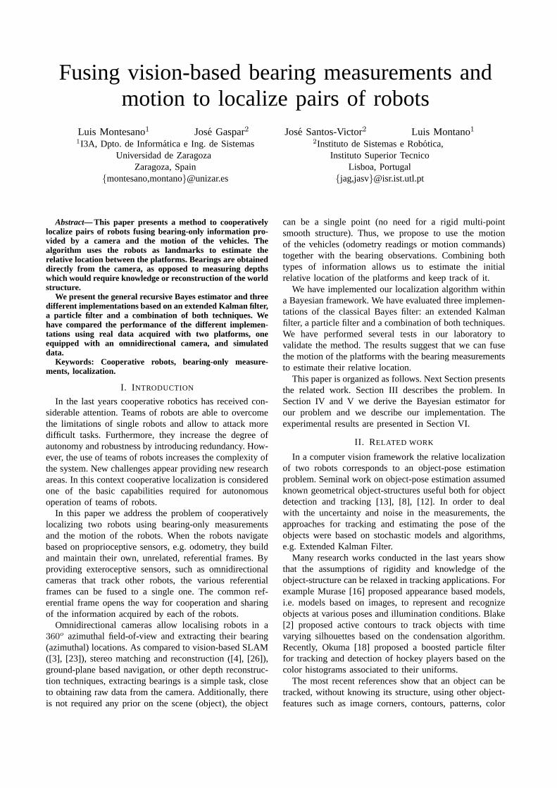
Fig. 1. Interpretation of the relative location between to movingplatforms. (a) world fixed reference system (b) robocentric approach.
patches, etc. A number of the tracking methods do notprovide pose estimation, due to the fact that feature modelsdo not contain structure information. However they obtainthe location of the object within the image. In the presentwork, we consider extracting bearing information from thelocation of one robot in the image acquired by anotherone and combining it with the motion of both platforms toestimate their relative localization.
On the other hand, cooperative localization has beenan active research area during the last years in therobotic community. There exist different approaches de-pending on several aspects as the information used(map availability, static/dynamic features) or the multi-robot architecture (communication capabilities, central-ized/decentralized). Related to this paper several authorshave used the robots as landmarks ([22], [10], [15]). Inthe absence of static references these methods estimate therelative pose among the robots instead of their location on aglobal reference system. However, all these algorithms userange-bearing sensors that provide an accurate estimationof their relative positions.
Some authors have used bearing-only measurements toestimate the location of the robots or the objects aroundthem [21], [24], [20]. The proposed algorithms usually useprobabilistic techniques to fuse the information providedby different sources with known uncertain locations atthe same time. To increase the robustness of an staticobject tracker Huster [11] fuses bearing information froma monocular camera and inertial rate sensors. In our casewe want to compute the relative location of two movingplatforms. Using only bearing information of the positionof the robots makes the problem non observable and weneed to incorporate some extra information, the motion ofthe platforms, to turn it solvable.
Finally, bearing-only information has also been studiedin other tracking contexts. For instance, Bar-Shalom in [1]shows how to apply the Extended Kalman Filter to estimatethe location of a constant velocity moving target and howthe trajectories of the observer improves the resulting esti-mation. Bearing-only measurements have also been used toshow improvements on particle filters for uniform straightmotion of the target [17]. Finally, Trawny [25] shows howdifferent motions result in different localization accuracies
OBSERVER
z(k)z(k+1)
z(k+2)
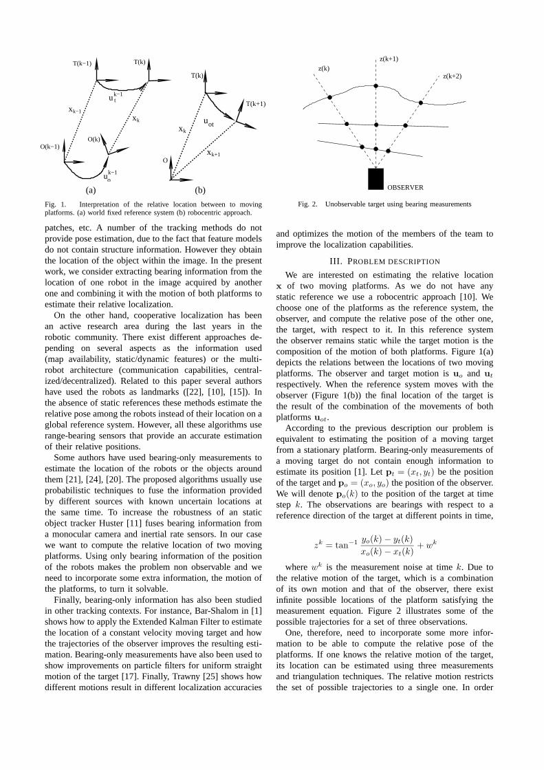
Fig. 2. Unobservable target using bearing measurements
and optimizes the motion of the members of the team toimprove the localization capabilities.
III. PROBLEM DESCRIPTION
We are interested on estimating the relative locationx of two moving platforms. As we do not have anystatic reference we use a robocentric approach [10]. Wechoose one of the platforms as the reference system, theobserver, and compute the relative pose of the other one,the target, with respect to it. In this reference systemthe observer remains static while the target motion is thecomposition of the motion of both platforms. Figure 1(a)depicts the relations between the locations of two movingplatforms. The observer and target motion isuo and ut
respectively. When the reference system moves with theobserver (Figure 1(b)) the final location of the target isthe result of the combination of the movements of bothplatformsuot.
According to the previous description our problem isequivalent to estimating the position of a moving targetfrom a stationary platform. Bearing-only measurements ofa moving target do not contain enough information toestimate its position [1]. Letpt = (xt, yt) be the positionof the target andpo = (xo, yo) the position of the observer.We will denotepo(k) to the position of the target at timestep k. The observations are bearings with respect to areference direction of the target at different points in time,
zk = tan−1 yo(k) − yt(k)
xo(k) − xt(k)+ wk
wherewk is the measurement noise at timek. Due tothe relative motion of the target, which is a combinationof its own motion and that of the observer, there existinfinite possible locations of the platform satisfying themeasurement equation. Figure 2 illustrates some of thepossible trajectories for a set of three observations.
One, therefore, need to incorporate some more infor-mation to be able to compute the relative pose of theplatforms. If one knows the relative motion of the target,its location can be estimated using three measurementsand triangulation techniques. The relative motion restrictsthe set of possible trajectories to a single one. In order
to incorporate the motion of the target one must estimatenot only its position but the whole location including theorientationxt = (xt, yt, θt).
When the observer is stationary there exist a degeneratedcase when the target moves on a straight line toward theobserver. In the case of two moving robots there mustbe some relative displacement between the platforms. Ifthe vehicles remain static, just rotate, move parallel oneto the other or move along the line joining them, thebearing measurements do not change. Moreover, dependingon the motion of the platforms the amount of informationprovided by the observations differs ([1], [19], [25]).
Finally, the method has to deal with the uncertainties andnoises in the system. As pointed out before, the sensormeasurements provide an initial relative location of therobots with a high uncertainty in the range and orientationof the target platform. Therefore, one has to be able to copewith a big initial uncertainty. In the next Section we presenta Bayesian estimation technique to estimate the relativepose of two moving vehicles using bearing measurementsand the trajectories of both vehicles.
IV. RELATIVE POSE ESTIMATION
We assume that the robots are able to measure theirown displacement. Letuk−1 be the motion of the robotbetween timek− 1 andk. The observer robot is equippedwith sensors that provide bearing measurementszk of theposition of the other robot at timek. We assume thatthe robots are synchronized and model the synchronizationerror as another source of noise in the system.
Let ro be the observer. We will denotezko the observa-
tions anduko the odometry readings obtained byro at time
k. Zko = {z1
o , ..., zko} and Uk
o = {u0o, ...,u
ko} represent
the observations and odometry readings of the observer upto time k. The target motion measurements up to timek
are Ukt = {u0
t , ...,ukt }. Our objective is to estimate the
relative locationx = (x y θ) of robot rt, the target, withrespect to robotro based on the information available up totime k. Thus, the posterior distribution we are estimatingis p(xk|Z
ko , Uk−1
o , Uk−1t ) and the corresponding recursive
Bayes filter is,
p(xk|Zko , Uk−1
o , Uk−1
t ) ∝ p(zko |xk) (1)
∫
p(xk | xk−1,uk−1
o ,uk−1
t )p(xk−1|Zk−1
o , Uk−2
o , Uk−2
t )dxk−1
where we have assumed a Markov process for boththe observationzk
o and the evolution ofx. The previousequation estimates the posterior at timek using the pos-terior computed at timek − 1, a motion modelp(xk |xk−1,u
k−1o ,uk−1
t ) and a measurement modelp(zko |xk).
V. I MPLEMENTATIONS OF THEBAYES ESTIMATOR
In this section we provide three different implementa-tions for equation (2): the classical Extended Kalman Filter(EKF), a sampled based approach known as particle filters(PF) and a combination of both techniques (PF-EKF).The EKF assumes Gaussian distributions and noises and
requires to linearize the process and measurement models.The lack of an accurate initial relative location makes theEKF unappropriated for the first stages of the estimation.In other words the EKF may diverge due to the initialuncertainty and the linearization error if the measurementsdo not contain enough information.
On the other hand particle filters do not require any ofthe previous assumptions and are able to represent anykind of distribution given a sufficient number of particles.However, they are computationally more expensive andintroduce a discretization error which depends on thenumber of particles used. Therefore, we propose an hybridapproach (PF-EKF) that uses a particle filter in the firststeps and switches to an EKF when the distribution of theparticles is close to a Gaussian.
The motion modelp(xk | xk−1,uk−1o ,uk−1
t ) takes intoaccount the motion of both platforms (see Figure 1),
p(xk | xk−1, Zk−1
o , Uk−1
o , Uk−1
t ) =
∫
p(xk|xk,uk−1
o ) (2)
p(xk|xk−1,uk−1
t )p(xk−1|Zk−1
o , Uk−2
o , Uk−2
t )dxk−1
To describe the motion of the platforms we use twooperators over reference systems: the composition⊕ andthe inversion⊖ of locations,
x1 ⊕ x2 =
cos θ1x2 − sin θ1y2 + x1
sin θ1x2 + cos θ1y2 + y1
θ1 + θ2
(3)
⊖x1 =
− cos θ1x1 − sin θ1y1
sin θ1x1 − cos θ1y1
−θ1
(4)
Using these operators the movement of the target plat-form seen from the observer is combination of the move-ments of each platform(see Figure 1(a)),
xk = f(xk−1,uk−1o ,uk−1
t ) = ⊖uk−1o ⊕ xk−1 ⊕ uk−1
t
whereut = (dxt, dyt, dθt) is the motion of the targetplatform anduo = (dxo, dyo, dθo) is the motion of theobserver platform. Note thatuk
t and uko are noisy mea-
surements of the true displacement of the robot corruptedwith noisesvk
t andvko respectively. On the other hand the
observation model is, as presented in Section III,
zko = h(x) + wk = tan−1 y(k)
x(k)+ wk (5)
wherewk is the measurement noise.
A. Extended Kalman filter implementation
In this section we implement Equation (2) using anEKF. The EKF framework models all the random variablesas gaussians and approximates the nonlinear process andmeasurement equations with the partial derivatives of thenonlinear functions. We denotex to the current estimateof the state vectorx and P to the associated covariance
x (meters)
y (m
eter
s)
2 4 6 8 10
−4
−2
0
2
4
0 1 2 3 4 5 6 7 8
−3
−2
−1
0
1
2
3
meters
met
ers
−1.5 −1 −0.5 00
1
2
3
4
5
6
meters
met
ers
(a) (b) (c)
Fig. 3. (a) observation model for the particle filter implementation, (b) initial distribution of particles, (c) the distribution after a given number ofsteps is close to a Gaussian
matrix. The odometry and bearing measurements are alsorepresented by their realizations,ut, uo, zo. The measure-ments are corrupted by independent white Gaussian noiseswith covariance matricesVt, Vo and R respectively.We use a first order approximation for the process andmeasurement models,
f(x,uo,ut) ≈ f(x, uo, ut) + ∇f
x − x
uo − uo
ut − ut
h(x) ≈ h(x) + ∇h(x − x)
where∇f is the Jacobian of the functionf with respectto the state vectorx and the odometry readingsuo andut and∇h is the Jacobian of the function vectorh withrespect to the state vectorx evaluated at the current statexk and motionsuo and ut.
Using the previous Jacobians we provide next the re-sulting Kalman filter equations for timek. The predictedrelative locationxk|k−1 using the linearized process modeland its associated covariance matrixPk|k−1 are,
xk|k−1 = f(xk−1, uk−1o , uk−1
t )
Pk|k−1 = ∇f
Pk−1 0 00 Vok
00 0 Vtk
∇Tf
with ∇f evaluated atxk−1, uk−1o
and uk−1
t. The
corresponding update step is,
Sk = ∇hPk|k−1∇Th + R, Wk = Pk|k−1∇
Th S−1
k
xk = xk−1 + Wkvk, Pk = Pk|k−1 − WkSkWTk
wherevk = zko − h(xk|k−1) is the innovation and the
Jacobian∇h is evaluated atxk|k−1.
B. Particle filter implementation
Particle filters are sequential Monte-Carlo techniquesto estimate posterior distributions [5]. They represent thedistributions by a set ofM samplesS = {x
[1]k , ...,x
[M ]k }.
The usual way to implement the recursive Bayes estimatorof Equation (2) is to use the posterior obtained in the
previous stepk − 1 and the motion model to guess thedistribution at timek. For each samplex[i]
k−1 a new sample
x[i]k is generated from the possible locations described by
uk−1o anduk−1
t ,
sample x[i]k from p(xk | x
[i]k−1,u
k−1o ,uk−1
t ) (6)
The set of all these samples conforms what is known asthe proposal distribution. For each robot we use a motionmodel similar to the one described in the Carnegie Mel-lon Navigation toolkit [14]. Note that we are composingtwo uncertain motions. The number of particles must besufficient to sample all the possible locations induced byboth motions requiring more particles than a single one.The samples from the proposal are distributed accordingto p(xk | Zk−1
o , Uk−1o , Uk−1
t ) and do not include theinformation of the last observationzk
o . To take into accountthe difference between the proposal distribution and thetarget distributionp(xk|Z
ko , Uk−1
o , Uk−1t ) the samples are
weighed according to their likelihood,
α[i] =target
proposal∝ p(zk
o |x[i]k ) (7)
The new set of particles approximatingp(xk|Z
ko , Uk−1
o , Uk−1t ) is then generated by sampling
from the proposal distribution according to the importancefactorsα[i].
The measurement model is the likelihood of the obser-vation given the current state. We model the noise of eachbearing as an independent zero mean Gaussian distributionwith a standard deviationσw,
p(zko |x
[i]k ) = N(zo;h(x
[i]k ), σw)
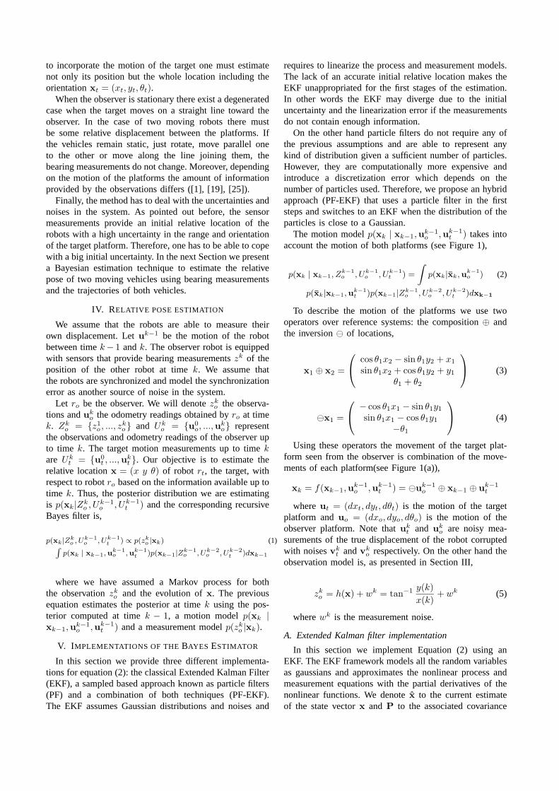
Figure 3(a) shows the likelihood model for a bearingmeasurement corresponding to thex axis. The darker thelocation is, the lower the likelihood associated to it.
C. Combining both approaches
In order to benefit from the advantages of each methodwe propose to use a combination of both techniques.During the first steps of the estimation process a Gaussiandistribution does not approximate well the uncertainty. As
(a)
−1 −0.5 0 0.5 1 1.5 2 2.5 3
0
0.5
1
1.5
2
2.5
3
meters
met
ers
labmatescout
(b) (c) (d)
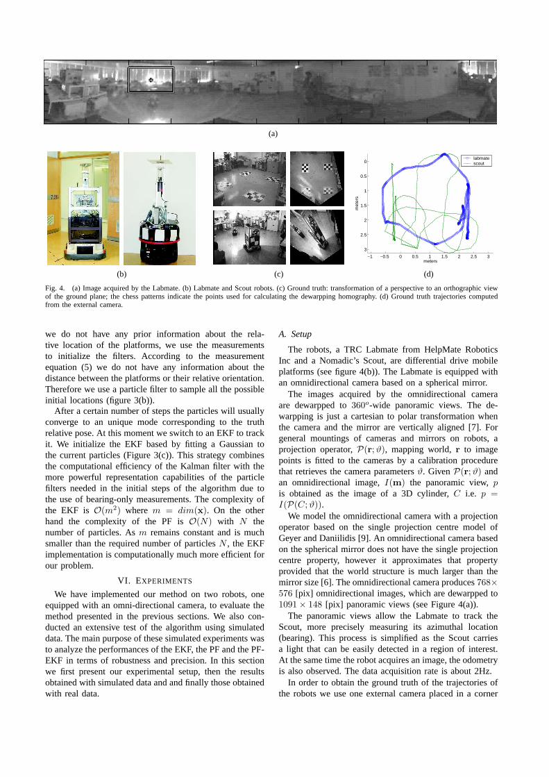
Fig. 4. (a) Image acquired by the Labmate. (b) Labmate and Scout robots. (c) Ground truth: transformation of a perspective to an orthographic viewof the ground plane; the chess patterns indicate the points used for calculating the dewarpping homography. (d) Ground truth trajectories computedfrom the external camera.
we do not have any prior information about the rela-tive location of the platforms, we use the measurementsto initialize the filters. According to the measurementequation (5) we do not have any information about thedistance between the platforms or their relative orientation.Therefore we use a particle filter to sample all the possibleinitial locations (figure 3(b)).
After a certain number of steps the particles will usuallyconverge to an unique mode corresponding to the truthrelative pose. At this moment we switch to an EKF to trackit. We initialize the EKF based by fitting a Gaussian tothe current particles (Figure 3(c)). This strategy combinesthe computational efficiency of the Kalman filter with themore powerful representation capabilities of the particlefilters needed in the initial steps of the algorithm due tothe use of bearing-only measurements. The complexity ofthe EKF is O(m2) where m = dim(x). On the otherhand the complexity of the PF isO(N) with N thenumber of particles. Asm remains constant and is muchsmaller than the required number of particlesN , the EKFimplementation is computationally much more efficient forour problem.
VI. EXPERIMENTS
We have implemented our method on two robots, oneequipped with an omni-directional camera, to evaluate themethod presented in the previous sections. We also con-ducted an extensive test of the algorithm using simulateddata. The main purpose of these simulated experiments wasto analyze the performances of the EKF, the PF and the PF-EKF in terms of robustness and precision. In this sectionwe first present our experimental setup, then the resultsobtained with simulated data and and finally those obtainedwith real data.
A. Setup
The robots, a TRC Labmate from HelpMate RoboticsInc and a Nomadic’s Scout, are differential drive mobileplatforms (see figure 4(b)). The Labmate is equipped withan omnidirectional camera based on a spherical mirror.
The images acquired by the omnidirectional cameraare dewarpped to360o-wide panoramic views. The de-warpping is just a cartesian to polar transformation whenthe camera and the mirror are vertically aligned [7]. Forgeneral mountings of cameras and mirrors on robots, aprojection operator,P(r;ϑ), mapping world,r to imagepoints is fitted to the cameras by a calibration procedurethat retrieves the camera parametersϑ. GivenP(r;ϑ) andan omnidirectional image,I(m) the panoramic view,pis obtained as the image of a 3D cylinder,C i.e. p =I(P(C;ϑ)).
We model the omnidirectional camera with a projectionoperator based on the single projection centre model ofGeyer and Daniilidis [9]. An omnidirectional camera basedon the spherical mirror does not have the single projectioncentre property, however it approximates that propertyprovided that the world structure is much larger than themirror size [6]. The omnidirectional camera produces768×576 [pix] omnidirectional images, which are dewarpped to1091 × 148 [pix] panoramic views (see Figure 4(a)).
The panoramic views allow the Labmate to track theScout, more precisely measuring its azimuthal location(bearing). This process is simplified as the Scout carriesa light that can be easily detected in a region of interest.At the same time the robot acquires an image, the odometryis also observed. The data acquisition rate is about 2Hz.
In order to obtain the ground truth of the trajectories ofthe robots we use one external camera placed in a corner
−1 0 1 2
−3
−2.5
−2
−1.5
−1
−0.5
0
meters
met
ers
ground truthestimated
−1 0 1 2
−3
−2.5
−2
−1.5
−1
−0.5
0
meters
met
ers
ground truthestimated
0 100 200 300 400 500 600 700 8000
0.2
0.4
0.6
0.8
1
1.2
1.4
iteration
met
ers
PF−EKFPF
(a) (b) (c)
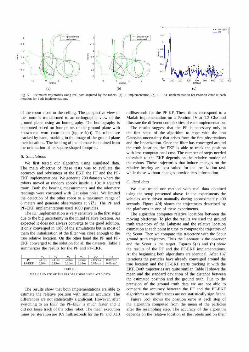
Fig. 5. Estimated trajectories using real data acquired by the robots. (a) PF implementation, (b) PF-EKF implementation (c) Position error at eachiteration for both implementations.
of the room close to the ceiling. The perspective view ofthe room is transformed to an orthographic view of theground plane using an homography. The homography iscomputed based on four points of the ground plane withknown real-word coordinates (figure 4(c)). The robots aretracked by hand, marking in the image of the ground planetheir locations. The heading of the labmate is obtained fromthe orientation of its square-shaped footprint.
B. Simulations
We first tested our algorithm using simulated data.The main objective of these tests was to evaluate theaccuracy and robustness of the EKF, the PF and the PF-EKF implementations. We generate 200 datasets where therobots moved at random speeds inside a10x10 squaredroom. Both the bearing measurements and the odometryreadings were corrupted with Gaussian noise. We limitedthe detection of the other robot to a maximum range of8 meters and generate observations at2Hz. The PF andPF-EKF implementations used 1000 particles.
The KF implementation is very sensitive in the first stepsdue to the big uncertainty in the initial relative location.Asexpected it does not always converge to the good solution.It only converged in40% of the simulations but in most ofthem the initialization of the filter was close enough to thetrue relative location. On the other hand the PF and PF-EKF converged to the solution for all the datasets. Table Isummarizes the results for the PF and PF-EKF.
µx σx µy σy µθ σθ
PF 0.11m 0.11m 0.10m 0.16m 0.07rad 0.08rad
PF-EKF 0.10m 0.15m 0.11m 0.18m 0.05rad 0.06rad
TABLE I
MEAN AND STD OF THE ERRORS USING SIMULATED DATA
The results show that both implementations are able toestimate the relative position with similar accuracy. Thedifferences are not statistically significant. However, afterswitching to an EKF the PF-EKF is much faster and itdid not loose track of the other robot. The mean executiontimes per iteration are 109 milliseconds for the PF and 0.13
milliseconds for the PF-KF. These times correspond to aMatlab implementation on a Pentium IV at 1.2 Ghz andillustrate the different complexities of each implementation.
The results suggest that the PF is necessary only inthe first steps of the algorithm to cope with the nonGaussian uncertainty that arises from the first observationsand the linearization. Once the filter has converged aroundthe truth location, the EKF is able to track the positionwith less computational cost. The number of steps neededto switch to the EKF depends on the relative motion ofthe robots. Those trajectories that induce changes on therelative bearing are best suited for the localization taskwhile those without changes provide less information.
C. Real data
We also tested our method with real data obtainedusing the setup presented above. In the experiments thevehicles were driven manually during approximately400seconds. Figure 4(d) shows the trajectories described bythe platforms in one of these experiments.
The algorithm computes relative locations between themoving platforms. To plot the results we used the groundtruth trajectory of the Labmate and the relative locationestimation at each point in time to compute the trajectory ofthe Scout. Then we compare this trajectory with the Scoutground truth trajectory. Thus the Labmate is the observerand the Scout is the target. Figures 5(a) and (b) showthe results of the PF and the PF-EKF implementations.At the beginning both algorithms are identical. After137iterations the particles have already converged around thetrue location and the PF-EKF starts tracking it with theEKF. Both trajectories are quite similar. Table II shows themean and the standard deviation of the distance betweenthe estimated position and the ground truth. Due to theprecision of the ground truth data we are not able tocompare the accuracy between the PF and the PF-EKFalgorithms as the differences are not statistically significant.
Figure 5(c) shows the position error at each step ofthe algorithm computed from the mean of the particlesafter the resampling step. The accuracy of the algorithmdepends on the relative location of the robots and on their
µx σx µy σy
PF 0.08m 0.06m 0.12m 0.09mPF-EKF 0.11m 0.07m 0.15m 0.10m
TABLE II
MEAN AND STD OF THE ERRORS USING REAL DATA
relative movement. During the first stages the error of bothalgorithms increases because the robots started moving inalmost parallel trajectories. Particles were spread due tothe noise in the odometry measurements. The measurementmodel is more precise for close locations. Those particlesplaced far away survived until the accumulated error inposition is bigger enough to be removed in the resamplingstep. As a result the mean of the particle filter was shiftedaway (see the trajectories of Figure 5(a) and (b)). Thissituation lasted until the Scout platform turned right andthe filter started to converge to the right relative location.
Once the method has converged the maximum errorfor both methods is around0.4 meters. The error peakscorrespond to those parts of the trajectory where the robotsare further (up to five meters). The further the robot is,the less informative is the observation in terms of possiblex − y positions. This makes that the estimation error andthe uncertainty of the relative location increase when theplatforms moved away one from the other.
VII. C ONCLUSIONS
We have presented a method to relatively localize a pairof robots fusing bearing measurements and the motion ofthe vehicles. Bearings are obtained as direct readouts of theomnidirectional camera. This is convenient as comparedto measuring depth, which would require knowledge orreconstruction of the world / robot structure.
We have proposed three different implementations of therecursive Bayes filter based on an Extended Kalman filter,a particle filter and a combination of both techniques. Thelatter combines the benefits of each type of filter resultingin a robust and fast algorithm. We have shown severalexperimental results validating the solution to the problemand evaluating the different implementations.
As future work we are currently extending the algorithmto the case where both robots have detection capabilities.We also plan to study the generation of motions for therobots that improve the accuracy of the relative localizationusing the estimation available at each step.
VIII. A CKNOWLEDGMENTS
This work has been partially supported by the Span-ish government under the project MCYT-DPI2003-7986and the Integrated Action HP2002-0037, and by the Por-tuguese government FCT Programa Operacional Sociedadede Informacao (POSI) in the frame of QCA III.
REFERENCES
[1] Y. Bar-Shalom, XR Li, and T. Kirubarajan. Estimation withApplications to Tracking and Navigation. J. Wiley and Sons, 2001.
[2] Andrew Blake and Michael Isard, editors.Active Contours: TheApplication of Techniques from Graphics, Vision, Control Theoryand Statistics to Visual Tracking of Shapes in Motion. Springer-Verlag, 1998.
[3] A. Davison. Real-time simultaneous localisation and mapping witha single camera. InIEEE International Conference on ComputerVision, pages 1403 – 1410 vol.2, 2003.
[4] A.J. Davison and D.W. Murray. Mobile robot localisationusingactive vision. InEuropean Conference on Computer Vision, 1998.
[5] A. Doucet, N. Freitas, and N.J. Gordon.Sequential Monte CarloMethods In Practice. Springer Verlag, 2001.
[6] J. Gaspar, E. Grossmann, and J. Santos-Victor. Interactive re-construction from an omnidirectional image. In9th InternationalSymposium on Intelligent Robotic Systems (SIRS’01), Toulouse,France, July 2001.
[7] J. Gaspar, N. Winters, and J. Santos-Victor. Vision-based navigationand environmental representations with an omni-directionalcamera.IEEE Transactions on Robotics and Automation, 16(6):890–898,December 2000.
[8] Donald B. Gennery. Visual tracking of known three-dimensionalobjects. International Journal of Computer Vision, 7(3):243–270,April 1992.
[9] C. Geyer and K. Daniilidis. A unifying theory for centralpanoramicsystems and practical applications. InEuropean Conference onComputer Vision (ECCV) 2000, pages 445–461, Dublin, Ireland,June 2000.
[10] A. Howard, M.J. Mataric, and G. Sukhatme. Putting the ’i’in ’team’:an ego-centric approach to cooperative localization. InIEEE Int.Conf. on Robotics and Automation, Taiwan, 2003.
[11] A. Huster and S. Rock. Relative position sensing by fusing monoc-ular vision and initial rate sensors. InInternational Conference onAdvanced Robotics, Coimbra, Portugal, 2003.
[12] D. Koller, K. Daniilidis, and H.-H. Nagel. Model-basedobjecttracking in monocular image sequences of road traffic scenes.International Journal of Computer Vision, 10(3):257–281, June1993.
[13] David G. Lowe. Robust model-based motion tracking throughthe integration of search and estimation.International Journal ofComputer Vision, 8(2):113–122, August 1992.
[14] M. Montemerlo, N. Roy, and S. Thrun. Perspectives on standardiza-tion in mobile robot programming: The carnegie mellon navigation(CARMEN) toolkit. In Proceedings of the Conference on IntelligentRobots and Systems (IROS), 2003.
[15] L. Montesano, L. Montano, and W. Burgard. Relative localizationfor pairs of robots based on unidentifiable moving landmarks. InInt. Conf. on Intelligent Robots and Systems, Sendai, Japan, 2004.
[16] H. Murase and S. K. Nayar. Visual learning and recognition of3D objects from appearance.Int. J. Computer Vision, 14(1):5–24,January 1995.
[17] C. Musso, N. Oudjane, and F. Le Gland.Sequential Monte CarloMethods In Practice, chapter Improving Regularised Particle Filters.Springer, 2001.
[18] K. Okuma, A. Taleghani, N. de Freitas, J. Little, and D. Lowe.A boosted particle filter: Multitarget detection and tracking. InEuropean Conference on Computer Vision, pages 28–39 vol.1, 2004.
[19] D.T. Pham. Some quick and efficient methods for bearing onlytarget motion analysis.IEEE Transactions on Signal Processing,41(9), 1993.
[20] P. Pinheiro and P. Lima. Bayesian sensor fusion for cooperativeobject localization and world modeling. InConference on IntelligentAutonomous Systems, Amsterdam, The Netherlands, 2004.
[21] M. Powers, R. Ravichandran, and T. Balch. Cooper-ative bearing-only tracking of multiple ambiguous targets.Submitted. Available online: www.cc.gatech.edu/ tucker/ pa-pers/2004AgentsMattPowers.pdf.
[22] S. Roumeliotis and G.A. Beckey. Distributed multirobot localiza-tion. IEEE Transactions on Robotics and Automation, 18(5), 2002.
[23] Stephen Se, D. Lowe, and J. Little. Mobile robot localization andmapping with uncertainty using scale-invariant visual landmarks.Int. Journal of Robotics Research, 21(8):735–758, 2002.
[24] J. Spletzer, K. Das, R. Fiero, C.J. Taylor, V. Kumar, and J.P.Ostrowski. Cooperative localization and control for multi-robotmanipulation. In Proceedings of the Conference on IntelligentRobots and Systems (IROS), Hawai, USA, 2001.
[25] N. Trawny and T. Barfoot. Optimized motion strategies forcooper-ative localization of mobile robots. InIEEE Int. Conf. on Roboticsand Automation, New Orleans, USA, 2004.
[26] R. Yang and M. Pollefeys. Multi-resolution real-time stereo oncommodity graphics hardware, proc. ieee conf. on computer visionand pattern recognition. InIEEE, Int. Conf. on Computer Vision(ICCV), pages 211–218, 2003.