fusheng li 李福胜 -...
TRANSCRIPT

Akademisk avhandling som med tillstånd av Kungl Tekniska Högskolan i Stockholm
framlägges till offentlig granskning för avläggande av doktorsexamen i kemi fredagen
den 26 februari kl 10.00 i sal F3, KTH, Lindstedtsvägen 26, Stockholm. Avhandlingen
försvaras på engelska. Opponent är Prof. Franc Meyer, Georg-August-Universität
Göttingen, Germany.
Design of Water Splitting Devices via
Molecular Engineering
Fusheng Li
(李福胜)
Doctoral Thesis
Stockholm, 2016

ISBN 978-91-7595-841-5
ISSN 1654-1081
TRITA-CHE Report 2016:6
© Fusheng Li, 2016
Universitetsservice US AB, Stockholm

To the people who ever helped me!


Fusheng Li, 2016: “Design of Water Splitting Devices via Molecular
Engineering”, School of Chemical Science and Engineering, KTH Royal
Institute of Technology, SE-100 44 Stockholm, Sweden.
Abstract
Converting solar energy to fuels such as hydrogen by the reaction of water
splitting is a promising solution for the future sustainable energy systems. The
theme of this thesis is to design water splitting devices via molecular
engineering; it concerns the studies of both electrochemical-driven and photo-
electrochemical driven molecular functional devices for water splitting.
The first chapter presents a general introduction about Solar Fuel Conversion.
It concerns molecular water splitting catalysts, light harvesting materials and
fabrication methods of water splitting devices.
The second chapter describes an electrode by immobilizing a molecular water
oxidation catalyst on carbon nanotubes through the hydrophobic interaction.
This fabrication method is corresponding to the question: “How to employ
catalysts in functional devices without affecting their performances?”
In the third chapter, molecular water oxidation catalysts were successfully
immobilized on glassy carbon electrode surface via electrochemical
polymerization method. The OO bond formation pathways of catalysts on
electrode surfaces were studied. This kinetic study is corresponding to the
question: “How to get kinetic information of RDS when a catalyst is
immobilized on the electrode surface?”
Chapter four explores molecular water oxidation catalysts immobilized on dye-
sensitized TiO2 electrode and Fe2O3 semiconductor electrode via different
fabrication methods. The reasons of photocurrent decay are discussed and two
potential solutions are provided. These studies are corresponding to the
question: “How to improve the stability of photo-electrodes?”
Finally, in the last chapter, two novel Pt-free Z-schemed molecular photo-
electrochemical cells with both photoactive cathode and photoactive anode for
visible light driven water splitting driven were demonstrated. These studies are
corresponding to the question: “How to utilize the concept of Z-scheme in
photosynthesis to fabricate Pt-free molecular based PEC cells?”
Keywords: electrochemical-driven water splitting, artificial photosynthesis,
molecular catalysts, photo-electrochemical cell, photo-electrodes,
electrochemistry, immobilization.

Sammanfattning på svenska
Omvandling av solens energi till bränsle, såsom väte genom sönderdelning av vatten,
utgör ett lovande alternativ för framtida hållbara energisystem. Huvudsyftet med denna
doktorsavhandling är att utforma elektrokemiska celler för sönderdelning av vatten, där
det huvudsakliga verktyget är molekylär design; både avseende funktionella
elektrokemiska och fotoelektrokemiska celler.
Det första kapitlet ger en allmän introduktion till forskningsområdet för omvandling till
solbränsle. Kapitlets innehåll fokuserar främst på molekylära katalysatorer för
sönderdelning av vatten, ljusabsorberande material och utformningen av
elektrokemiska och fotoelektrokemiska celler.
Det andra kapitlet beskriver hur en elektrod för vattenoxidation kan
konstrueras genom immobilisering av en molekylär katalysator på ytan av
kolnanotuber genom utnyttjande av deras hydrofoba interaktion.
Tillverkningsmetoden adresserar frågan: ”Hur kan katalysatorer användas i
funktionella enheter utan att deras funktion påverkas?”
I det tredje kapitlet beskrivs hur en molekylär katalysator för sönderdelning av vatten
kan immobiliseras på en elektrodyta av glasaktigt kol med hjälp av en elektrokemisk
polymerisationsmetod. Mekanismen för katalysen av O-O-bindningar vid elektrodytan
studerades i detalj. Denna kinetiska studie berör frågan: ”Hur kan man erhålla
kinetisk information om det hastighetsbestämmande steget i en katalytisk process
då katalysatorn är bunden till en elektrodyta?”
Kapitel fyra ägnas åt studier av katalysatorer för sönderdelning av vatten, vilka genom
olika tillverkningstekniker immobiliserats på färgämnessensiterade elektroder eller
halvledande elektroder bestående av Fe2O3. Orsaken till den observerade minskningen
av fotoströmmen diskuteras och två möjliga orsaker identifieras. Dessa delstudier är
relaterade till frågan: ”Hur kan stabiliteten av fotoelektroder förbättras?”
Slutligen, i det sista kapitlet beskrivs två nya molekylära fotoelektrokemiska
celler av tandemtyp utan användning av platina. I dessa celler används både en
fotoaktiv katod och fotoaktiv anod för att driva sönderdelningen av vatten med
hjälp av synligt ljus. Dessa celler hänför sig till frågan: ”Hur kan Z-konceptet
användas för att tillverka molekylära fotoelektrokemiska celler utan
användning av platina?”
Nyckelord: elektrokemisk sönderdelning av vatten, artificiell fotosyntes,
molekylära katalysatorer, fotoelektrokemisk cell, fotoelektroder, elektrokemi,
immobilisering.

Abbreviations
APT atomic proton transfer
bpy 2,2-bipyridine
CB conduction band
CeIV cerium (IV) ammonium nitrate, Ce(NH4)2(NO3)6
CV cyclic voltammetry
DFT density functional theory
DMSO dimethyl sulfoxide
DPV differential pulse voltammetry
E0 standard potential of a reaction, redox couple and electrode
E1/2 half-wave potential in voltammetry
GC glassy carbon
H2BDA 2,2-bipyridine-6,6-dicarboxylic acid
HGC hydrogen generation catalyst
H2PDA 1,10-phenanthroline-2,9-dicarboxylic acid
H2PDC 2,6-pryidinedicarboxylic acid
IPCE incident photon-to-electron conversion efficiency
I2M interaction of two M−O units
LSV linear scan voltammetry
MS mass spectrometry
NHE normal hydrogen electrode
NMR nuclear magnetic resonance
OEC oxygen-evolving-complex
PCET proton coupled electron transfer
PDC 2,6-pyridinedicarboxylic acid
pic 4-picoline
PS I photosystem I
PS II photosystem II
PV photovoltaic

py pyridine
tpy 2,2 - 6, 2-terpyridine
TOF turnover frequency
TON turnover number
RDS rate determining step
RC radical coupling
WNA water nucleophilic attack
WOC water oxidation catalyst
VB valence band
ƞ over potential of catalytic reaction
2-E two-electrode
3-E three-electrode

List of Publications
This thesis is based on the following papers, referred to in the text by their
Roman numerals I-VI:
I. Immobilization of a molecular catalyst on carbon nanotubes for
highly efficient electro-catalytic water oxidation
Fusheng Li, Lin Li, Lianpeng Tong, Quentin Daniel, Mats Göthelid, and
Licheng Sun
Chem. Commun. 2014, 50, 13948-13951.
II. Control the OO bond formation pathways by immobilizing
molecular catalysts on glassy carbon via electrochemical
polymerization
Fusheng Li, Lele Duan, Ke Fan, Lei Wang, Quentin Daniel, Hong Chen,
and Licheng Sun
Manuscript
III. Immobilizing Ru(BDA) catalyst on a photoanode via
electrochemical polymerization for light-driven water splitting
Fusheng Li, Ke Fan, Lei Wang, Quentin Daniel, Lele Duan, and
Licheng Sun
ACS Catal. 2015, 5, 3786−3790.
IV. Immobilization of a molecular ruthenium catalyst on hematite
nanorod arrays for water oxidation with stable photocurrent
Ke Fan,† Fusheng Li,
† Lei Wang, Quentin Daniel, Hong Chen, Erik
Gabrielsson, Junliang Sun, and Licheng Sun († authors contributed
equally to this work)
ChemSusChem 2015, 8, 3242-3247.
V. Pt-free tandem molecular photoelectrochemical cells for water
splitting driven by visible light
Ke Fan,† Fusheng Li,
† Lei Wang, Quentin Daniel, Erik Gabrielsson, and
Licheng Sun († authors contributed equally to this work)
Phys. Chem. Chem. Phys. 2014, 16, 25234-25240.
VI. Dye-Sensitized tandem photoelectrochemical cell for light driven
total water splitting
Fusheng Li, Ke Fan, Bo Xu, Erik Gabrielsson, Quentin Daniel, Lin Li,
and Licheng Sun
J. Am. Chem. Soc. 2015, 137, 9153-9159.

Papers not included in this thesis:
VII. Highly Efficient Bioinspired Molecular Ru Water Oxidation
Catalysts with Negatively Charged Backbone Ligands
Lele Duan, Lei Wang, Fusheng Li, Fei Li, and Licheng Sun
Acc. Chem. Res. 2015, 48, 2084−2096
VIII. Sensitizer-Catalyst Assemblies for Water Oxidation
Lei Wang, Mohammad Mirmohades, Allison Brown, Lele Duan,
Fusheng Li, Quentin Daniel, Reiner Lomoth, Licheng Sun and Leif
Hammarström
Inorg. Chem. 2015, 54, 2742-2751.
IX. Electrochemical Driven Water Oxidation by Molecular Catalysts in
situ Polymerized on the Surface of Graphite Carbon Electrode
Lei Wang, Ke Fan, Quentin Daniel, Lele Duan, Fusheng Li, Bertrand
Philippe, Håkan Rensmo, Hong Chen, Junliang Sun, and Licheng Sun
Chem. Commun. 2015, 51, 7883-7886.
X. Dipicolinic acid: a strong anchoring group with tunable redox and
spectral behavior for stable dye-sensitized solar
Erik Gabrielsson, Haining Tian, Susanna K Eriksson, Jiajia Gao, Hong
Chen, Fusheng Li, Johan Oscarsson, Junliang Sun, Håkan Rensmo, Lars
Kloo, Anders Hagfeldt, and Licheng Sun
Chem. Commun. 2015, 51, 3858-3861.
XI. Visible light-driven water oxidation using a covalently-linked
molecular catalyst–sensitizer dyad assembled on a TiO2 electrode
Masanori Yamamoto, Lei Wang, Fusheng Li, Takashi Fukushima, Koji
Tanaka, Licheng Sun, and Hiroshi Imahori
Chem. Sci., 2016, DOI: 10.1039/C5SC03669K
XII. Tailored design for RuBDA water oxidation catalyst
Quentin Daniel, Lei Wang, Lele Duan, Fusheng Li, and Licheng Sun
Manuscript.
XIII. Rearranging from 6- to 7- coordination initiates the catalytic
activity: an EPR study on a Ru-BDA water oxidation catalyst
Quentin Daniel, Ping Huang, Ting Fan, Lele Duan, Lei Wang, Fusheng
Li, Mårten Ahlquist, Fikret Mamedov, Stenbjörn Styring, Licheng Sun
Manuscript.
XIV. 3D-Structured Nickel-Vanadium Monolayer Double Hydroxide for
Efficient Electrochemical Water Oxidation
Ke Fan, Hong Chen, Yongfei Ji, Hui Huang, Per M. Claesson, Quentin
Daniel, Philippe Bertrand, Håkan Rensmo, Fusheng Li, Yi Luo, and
Licheng Sun
Manuscript.

5
Table of Contents Abstract Abbreviations List of publications
1. Introduction ..................................................................................... 1 1.1. Solar Fuels ‒ two different approaches ................................................ 2 1.2. Indirect approach: PV-electrolyzer ........................................................ 3 1.3. Direct approach: Photosynthesis .......................................................... 4
1.3.1. Natural Photosynthesis ............................................................................ 4 1.3.2. Artificial Photosynthesis - integrated assembly systems ........................... 5 1.3.3. Artificial Photosynthesis - photoelectrochemical cells ............................... 6
1.4. Catalysts for Solar Fuel Conversion ..................................................... 8 1.4.1. Water Oxidation Catalysts ........................................................................ 8 1.4.2. Hydrogen Generation Catalysts ..............................................................11
1.5. Light Harvesting Materials for Artificial Photosynthesis ...................... 11 1.5.1. Semiconductors ......................................................................................12 1.5.2. Molecular Photosensitizers .....................................................................13
1.6. Functional electrodes for water splitting .............................................. 14 1.6.1. Electrochemical-driven water splitting .....................................................15 1.6.2. Light-driven water splitting ......................................................................18
1.7. Challenges for Solar to Fuel Conversion ............................................ 23 1.8. The Aim of This Thesis ....................................................................... 24
2. Immobilization of a Molecular Catalyst on Carbon Nanotubes for
Highly Efficient Electrochemical-driven Water Oxidation ........................ 25 2.1. Introduction ......................................................................................... 27 2.2. Synthesis ............................................................................................ 27 2.3. Results and Discussions ..................................................................... 28
2.3.1. Electrochemical properties .......................................................................28 2.3.2. Preparation of Electrode ..........................................................................29 2.3.3. Electro-driven Water Oxidation ................................................................30
2.5. Summary ............................................................................................ 33 3. Control the O‒O bond formation pathway by immobilizing
molecular water oxidation catalysts on the electrode surface ................. 35 3.1. Introduction ......................................................................................... 37 3.2. Design, Synthesis and Preparation of Electrodes ............................... 38 3.3. Results and Discussions ..................................................................... 39
3.3.1. CH3CN ligand exchange ..........................................................................39 3.3.2. pH Dependent Electrochemistry ...............................................................40 3.3.3. Methods for Electrode Kinetics.................................................................41 3.3.4. The O‒O Bond Formation Pathways on Electrodes .................................43
3.4. Summary ............................................................................................ 49 4. Immobilizing Ru catalysts on photoanodes for light-driven water
splitting..................................................................................................... 51

4.1. Introduction ......................................................................................... 53 4.2. Synthesis and Preparation of Electrodes ............................................ 54 4.3. Results and Discussions ..................................................................... 55
4.3.1. Electrochemical Properties ......................................................................55 4.3.2. Photo-Electrochemistry ............................................................................56 4.3.3. Kinetics Study ..........................................................................................57 4.3.4. Replacement of the Molecular Photosensitizer by α-Fe2O3 ......................59
4.4. PDC as the Anchoring Group for Photoanode .................................... 60 4.5. Summary ............................................................................................ 62
5. Dye-sensitized tandem PEC cells for light driven total water
splitting by employing the concept of Z-scheme ..................................... 65 5.1. Introduction ......................................................................................... 67 5.2. Rational Design of Tandem Dye-sensitized PEC cells ....................... 68 5.3. Synthesis and Preparation of Electrodes ............................................ 68 5.3. Results and Discussions ..................................................................... 69
5.3.1. Electrochemical Properties ......................................................................69 5.3.2. Photo-Electrochemistry ............................................................................70
5.4. Redesign and Replacement of RuP.................................................... 72 5.5. Summary ............................................................................................ 79
6. Concluding Remarks .................................................................... 81 7. Future prospects ........................................................................... 83 Acknowledgements ................................................................................. 84 Appendix A .............................................................................................. 85 References .............................................................................................. 86

1
1. Introduction
Energy plays a crucial role in the development of modern human society.
Nowadays, our energy systems are mainly produced from fossil fuels such as
petroleum, natural gas and coal.1 Unfortunately, global energy demand and
consumption are rapidly increasing with both the expansion of population and
the improvement of living standard, leading to the extensive use of fossil fuels
and consequently giving rise to problems such as environmental pollution,
global warming crisis and sulfur dioxide emissions etc.. As a result of
continuous combustion of carbon-based fuels, the unacceptable changes of the
Earth‟s climate start to occur. All these issues point to the requirement of new
sustainable, carbon-neutral energy systems.2
With the advantage of renewable and carbon-neutral properties, hydrogen is
considered as a green energy carrier with a high energy density by weight.
Currently, hydrogen is mainly produced from fossil fuels by steam reforming,
partial oxidation of methane and coal gasification, which are of course not
sustainable and carbon-neutral approach. Producing hydrogen by splitting
water with renewable electricity or artificial photosynthesis is considered to be
an ideal way for developing sustainable energy systems.3,4
There are two half reactions consisted in the whole water splitting process: (I)
water oxidation, where two water molecules are oxidized to one molecular
oxygen and four protons are produced (eqn. 1); (II) proton reduction, where
protons are reduced to hydrogen (eqn. 2).
Sunlight is clean and highly abundant energy source on the Earth. Utilization
of solar energy to produce energy-rich hydrogen by the splitting of water (eqn.
3) is one of the most promising approaches.5-8
This carbon-neutral chemical
reaction just requires the free energy source (sunlight) and nearly unlimited
starting materials (H2O) and produces only one byproduct (O2).9 To reduce the
energy barrier and accelerate water splitting reactions, great efforts in this field
have been devoted to develop highly efficient water oxidation catalysts (WOCs)
and hydrogen generation catalysts (HGCs).10,11
However, for the future
application, several other challenges still need to be addressed. One of the
most challenging tasks is: how to employ these catalysts to build functional
devices? Fabrication of molecular-precise architectures confined at interfaces
through molecular engineering can provide efficient and versatile tools for
building functional electrodes.

2
1.1. Solar Fuels ‒ two different approaches
Converting solar energy to hydrogen and oxygen through water splitting
reaction has been considered as a promising idea for a long time. Jules Verne
wrote that: “water will be the coal of the future”in his fiction “The Mysterious
Island” in 1874. Since sunlight is the most abundant energy source on the
Earth, and there are two approaches that can be used to convert solar energy to
fuels such as hydrogen (as shown in Figure 1). One is indirect approach, in
which solar electricity is produced by photovoltaic (PV) devices and then used
to produce hydrogen by electrolysis of water. The other one is an direct
approach, where solar energy can be used to produce hydrogen by splitting
water.1
Figure 1. Renewable fuels generation ‒ two different approaches.
The photovoltaic cell is one of the most popular solar technologies and it
clearly has great potential for serving carbon-free energy. However, electricity
cannot drive everything! According to the electricity statistics of International
Energy Agency (IEA), only 22% of the total energy production will be used as
electricity in 2030, which means we still need a huge amount of energy in the
form of fuels. On the other hand, solar cell technologies can only convert
sunlight into electricity which is hard to be stored in big capacity for
transportation and nighttime use.
Instead of direct utilization, the electricity can be used in device such as
electrolyzer to produce hydrogen from water, which is an energy storage
process. This indirect approach can be easily designed by employing
appropriate catalysts, electrodes and electrolytes in the electrolyzer, and solar
energy is converted to electricity by solar cells to drive the water splitting
reaction.
The second approach is more straightforward. Similar to the natural
photosynthesis system, solar energy is directly collected and used to produce
hydrogen by the reaction of water splitting, without intermediate energy
carriers (such as solar electricity). This approach is called “Artificial

3
Photosynthesis”, which is an example of a direct pathway for storage of solar
energy.8
Both of the direct and indirect approaches are chemical processes for storing
energy from sunlight into chemical bonds of fuels (solar fuels). In this thesis,
two topics of electrochemical-driven water splitting (electrolyzer) and light-
driven water splitting (artificial photosynthesis) will be discussed.
1.2. Indirect approach: PV-electrolyzer
For the indirect approach, a PV-electrolyzer device is used to carry out solar-
to-fuels conversion (as shown in Figure 2). Efficient PVs and electrolyzers
with high faradaic efficiency are required.12,13
The solar-to-fuels conversion
efficiency (SFE) for a PV-electrolyzer device can be calculated by eqn.4,13-16
where Jop is the point of intersection and gives the operation current density, V
is the water splitting potential required (1.23 V), Plight is incident light power
and ηF is faradaic efficiency.
0.0 0.5 1.0 1.5 2.0S
FE
%
Cu
rre
nt
de
nsity
Voltage (V) Figure 2. (left)Schematic diagrams of the PV-electrolyzer device. (right) the
relationship between solar to fuel efficiency (SFE), the performances of PV and
electrolyzer, red lines are the J-V curves of PV, solid line means PV with higher
efficiency. Blue lines are the linear sweep voltammetry ( LSV) curves of electrolyzer.
Solid line means electrolyzer with higher activity and lower over potential.
From the crossing points of PV curves and LSVs, we can find that by
combining a high efficiency PV with a high active electrolyzer, a high Jop can
be obtained, correspondingly, resulting in a highly solar-to-fuels conversion
efficiency. Much effort has been devoted to the development of high efficiency
PVs. Unfortunately, the cost per watt of solar photovoltaic electricity is still
presently too high for a practical water splitting device.
2
water splitting
-2
( [ ] ( 1.23V) ). 4
[mWcm ]
op F
light
J mAcm VSFE eqn
P

4
On the other side, due to the presence of over-potentials for both half reactions
(oxygen-evolution reaction-OER and hydrogen-evolution reaction-HER) and
the resistance losses in the electrolyzer (such as contact resistance, solution
resistance and the resistance of electrodes), the actual voltage (Vactual) required
is always higher than the ideal thermodynamic potential of 1.23V. The Vactual
can be described by eqn. 5.
1.23V .5OER HERactualV iR eqn
For the principle of PV-electrolyzer devices design, electrodes (cathode and
anode) with both low over-potentials and high activities for water splitting are
urgently needed to minimize the value of Vactual, which highly depends on the
properties of catalysts and electrode fabrication methods.
1.3. Direct approach: Photosynthesis
1.3.1. Natural Photosynthesis
In nature, solar energy can be collected and stored as carbohydrates and other
biomass. However, natural photosynthesis is not very efficient (yields of
biomass efficiencies is usually less than 1%).17
But natural photosynthesis
system provides an ideal blue print of solar energy conversion.18
In nature,
water oxidation is catalyzed by an oxygen-evolving-complex (OEC, a
Mn4CaO5 cluster) in the enzyme of photosystem II (PS II) driven by sunlight.
Through an electron transportation chain,i the electrons extracted from water
are delivered to photosystem I (PS I) where they are pumped to a higher
energy level for the conversion of NADP+ to NADPH. At the same time,
energy also can be used to convert ADP to ATP during the electron transfer
process.19
Figure 3. Simplified Z-scheme of light-induced reaction for natural photosynthesis.
i Electron transport chain in Z-scheme. ET = electron transport. i) OEC→Tyr→P680. ii)
P680*→Pheo→Qa→Qb→Cyt b6f→PC→P700. iii) P700*→A0→A1→Fx/a/b→FD→FNR. Tyr =
tyrosine; Pheo= pheophytin; Qa and Qb =Quinones A and B; Cyt b6f = an Fe-S Rieske center complex; PC = plastoquinone binding sites; A0 = chlorophy II; A1 = phylloquinone; Fx/a/b = three
separated Fe-S protein; FD = ferredoxin; FNR = ferredoxin-nicotinamide-adenine dinucleotide
phosphate reductase; P680 and P700 = pigments with absorption maximum at 680nm or 700nm.

5
In this whole process, known as the Z-scheme (as shown in Figure 3), P680 in
PS II and P700 in PS I are the light-harvesting antennas, which create light-
induced charge separations when they are excited (collecting solar energy).
Meanwhile, water serves as electron and proton donor to produce the energy-
carrying agents (ATP and NADPH) for the “dark” reaction where CO2 is
converted to carbohydrates (storing solar energy).
Collecting and storing solar energy into chemical bonds, as nature
accomplishes through the fantastic photosynthesis, is a highly desirable
approach to solve the energy challenges.6 This Z-scheme provides scientists a
general direction for how to create artificial photosynthesis systems with man-
made materials.20
1.3.2. Artificial Photosynthesis - integrated assembly systems
There is no doubt that artificially duplicating any functional components of
natural photosynthesis is a tremendous challenge. For artificial photosynthesis
system, two different strategies are currently accepted, one is an integrated
assembly (IA) system, and the other one is a photo-electrochemical cell (PEC
cell). Usually the IA systems are molecular or particle devices (as shown in
Figure 4), in which electron-hole pairs are generated by the light-induced
charge-separation from chromophores (dye molecules or light-absorbing
semiconductors), then electrons are transferred to the HGC for hydrogen
generation. Simultaneously, holes are transferred to the WOC for the oxidation
of water.
Figure 4. Schematic diagrams of integrated assembly systems, a) molecular dye system.
b) Single-step semiconductor particle with attached HGC and WOC as co-catalysts. c)
Mixture of semiconductor particles with attached HGC or WOC as co-catalysts and
redox electrolyte couples.
As shown in Figure 5, several principal requirements must be met for the
design of the integrated assembly systems. Thermodynamically, the LUMO
level of chromophores must be more negative than the onset potential of HGC,
and the HOMO level of chromophores must be more positive than the onset
potential of WOCs. Kinetically, the electron transfer between the excited state
of chromophores and catalysts must be fast enough to avoid the quenching of

6
chromophores* by other processes (charge recombinations etc.). As these
integrated assembly systems are homogeneous or semi-homogeneous reactions,
the hydrogen and oxygen gases generated during the water splitting process are
present as a mixture in the same reaction chamber.7
Figure 5. Schematic diagram of the simplified electron flows and related potentials for
integrated assembly water splitting systems.
1.3.3. Artificial Photosynthesis - photoelectrochemical cells
The so-called PEC cell is based on the integration of functional materials with
electrodes, in which the water oxidation and hydrogen generation sites are
separated on two different electrodes.
Figure 6. Schematic diagrams, PEC cells with one photo-active electrode. Left, a
photoanode works as photo-active center. Right, a photocathode works as photo-active
center
7
The working principles of PEC cells are shown in Figure 6. When a
photoanode combined with a counter electrode (Figure 6 left), the electrons
are extracted from water by light-induced charge-separation generated from
the chromophore, and pumped to the counter electrode where the hydrogen
generation reaction occurs. In this case, the photoanode is the photo-active
center. A photocathode can also be the photo-active center with the similar
device structure, as shown in Figure 6 right. Due to the thermodynamic
requirements, for example, when a photoanode combined with Pt (as HGC),
the LUMO level (or the conduction band corresponding to the semiconductor)
of chromophore must be more negative than the onset potential of Pt for
hydrogen generation, and the HOMO level (or valence band corresponding to
the semiconductor) must be more positive than the onset potential of WOC for
water oxidation. Nonetheless, chromophores usually cannot meet these two
requirements at the same time. As a result, the properties of photoanodes or
photocathodes are more extensively studied instead of whole PEC devices, in
which three-electrode (3-E) setups are employed, bias are usually needed to
balance the charge transfer between working and counter electrodes, and
counter electrodes obtain extra energy from potentiostat.
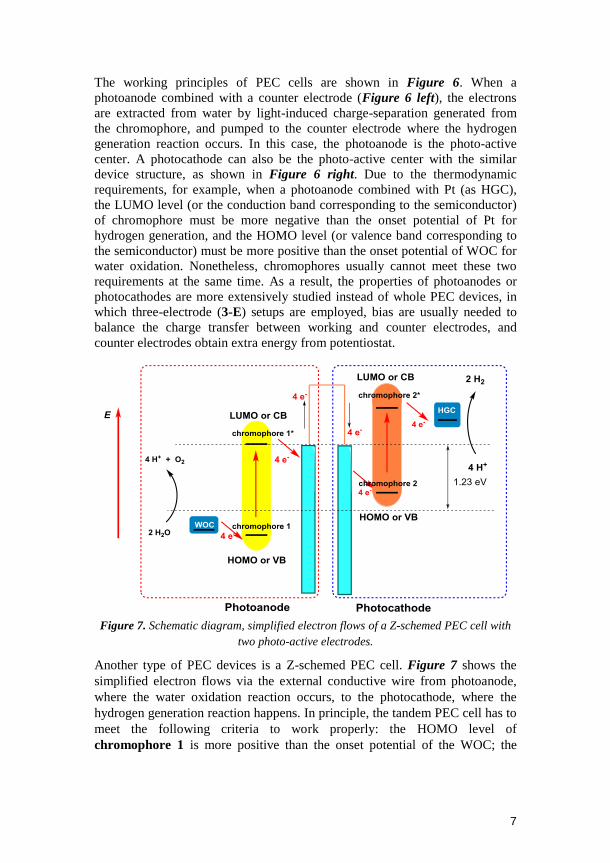
Figure 7. Schematic diagram, simplified electron flows of a Z-schemed PEC cell with
two photo-active electrodes.
Another type of PEC devices is a Z-schemed PEC cell. Figure 7 shows the
simplified electron flows via the external conductive wire from photoanode,
where the water oxidation reaction occurs, to the photocathode, where the
hydrogen generation reaction happens. In principle, the tandem PEC cell has to
meet the following criteria to work properly: the HOMO level of
chromophore 1 is more positive than the onset potential of the WOC; the

8
LUMO level of chromophore 2 is more negative than the onset potential of
the HGC; and the LUMO level of chromophore 1 is more negative than the
HOMO level of chromophore 2. Two chromophores with different spectra
can expand the solar light absorption of PEC cells. Comparing to single photo-
active electrode PEC devices, Z-schemed PEC cells have two light harvesting
units: one handles the water oxidation reaction and the other manages the
hydrogen generation reaction. In theory, extra bias potentials can be avoided.
Meanwhile, both electricity and solar fuels can be generated from the Z-
schemed PEC cell at the same time. Solar energy conversion by a Z-schemed
PEC cell is very similar to the natural photosynthesis. They all share the same
functional components (water as the electron/proton donor, two light
harvesting centers as well as two charge pumping processes) and similar
energy storage processes (hydrogen corresponding to NADPH, electricity
corresponding to ATP).
To date, due to the difficulty in matching the energy levels of both photo-
active electrodes, molecular Z-schemed PEC cells are rarely reported. In this
thesis, our efforts on the design of molecular Z-schemed PEC cells will be
demonstrated.
1.4. Catalysts for Solar Fuel Conversion
No matter which device configuration is employed for solar fuel generation,
the kinetics of the water splitting reaction is a key element. Therefore to
accelerate the water splitting reaction, incorporating the electrode surface with
efficient WOCs and HGCs is highly required.
1.4.1. Water Oxidation Catalysts
Water oxidation requires simultaneous transfer of four protons and four
electrons from two water molecules and therefore is the bottleneck of the full
water splitting process.10,11
Water oxidation catalysts can be divided into inorganic materials and
molecular catalysts. For inorganic materials, typical WOCs include metal
oxides, such as Ir-, Ru-, Fe-, Co-, Ni-, and Mn-based transition-metal oxides.21-
26 In this thesis, we focus on the molecular catalysts; metal oxide based WOCs
are beyond the scope of this thesis and will not be discussed.
Molecular WOCs, especially, Ruthenium based complexes have drawn much
attention because they can be easily modified structurally and electronically,
and their ability of mediating multiple-electron transfer reactions can provide
opportunities for comprehensive mechanistic studies.20,27-41

9
A few well-known Ru-based WOCs are representatively shown in Figure 8. In
1982 the first Ru-based molecular WOC so called “blue dimer” 1 was reported
by Meyer et al. with a turnover number (TON) of 13 and turnover frequency
(TOF) of 0.004 s-1
.36
From then on, bimolecular Ru WOCs have been rapidly
developed through tailored ligand design, Thummel‟s complex 2 exhibits
larger TON and TOF toward CeIV
-driven water oxidation.39
Recently Franc
Meyer et al. reported a novel binuclear Ru-WOC 3 based on a specific ligand
tailoring design and the performance of this catalyst has been systematically
improved. The study on complex 3 also demonstrated how subtle ligand
modifications cause a change in the O−O bond formation mechanism, which is
very instructive.34
Figure 8. Structures of bimolecular and monomolecular Ru WOCs and their catalytic
performances are given in the form of (TON, TOF) based on Ce(NH4)2(NO3)6 as the
oxidant at pH = 1, the TOF of Mn4CaO5 cluster (OEC of PS II) is also given.ii
ii TON and TOF are two major parameters to exam the catalytic performances of catalysts. Water
soluble single-electron chemical oxidant [Ce(NH4)2(NO3)6] (CeIV) is usually used to evaluate
catalytic activity of molecular WOCs in aqueous medium. CeIV has a very high oxidation potential
around 1.7 V at pH 0. The corresponding electron-accepting half reaction and total reaction are described as follows:

10
In 2005, Thummel et al. published the first monomolecular Ru WOC 5 with a
TON of 260 and TOF of 0.014 s-1
.39
Since then, the catalytic performances of
monomolecular Ru WOCs have been significantly improved. Among them, the
star molecules [Ru(BDA)L2] (BDA2
= 2,2-bipyridine-6,6-dicarboxylate; L =
N-cyclic aromatic ligands) can achieve the highest TOF of 1000 s-1
(8) and the
highest TON of 100 000 (9).42
It takes only 32 years that the artificial WOCs
have already obtained a much better activity than the oxygen-evolving-
complex from Photosystem II!
Studies on Ru-based WOCs, as model complexes, can not only provide the
information about the structure-performance correlations for the design of non-
noble metal WOCs, but also give chemists a deeper understanding of the
mechanism for the O-O bond formation.
The O-O bond formation is the most important step for water oxidation, there
are two widely accepted pathways for Ru WOCs as described in eqn. 6 and
eqn .7.31
One is water nucleophilic attack (WNA) pathway (eqn. 6), in which a
water molecule nucleophilically attacks the oxo group of RuV=O, resulting in a
two-electron reduction of RuV=O and the O-O bond formation. Most Ru-based
WOCs catalyze water oxidation through the WNA pathway.
Another pathway is the radical coupling (RC) pathway as described in eqn. 7,
in which two mono-radical RuIV
-O∙ units couple with each other, forming a
peroxo intermediate. [Ru(BDA)L2] catalyzes water oxidation through the RC
pathway.
Recently, several molecular WOCs based on first-row transition-metal such as
Mn, Fe, Co, Ni and Cu have been developed.43-53
Although the catalytic
mechanism and structure-activity correlation of these WOCs are still not
known as much as that of Ru-based WOCs, they are very attractive for opening
up the way to develop WOCs based on earth-abundant elements.
In this thesis, complexes 6 (WNA catalyst) and 7 (RC catalyst) are selected as
model complexes for electrodes modification via different fabrication methods.
With the rapid development of WOCs, we hope our approaches and methods
will inspire the research on non-noble metal WOCs-based water splitting
devices in the future.

11
1.4.2. Hydrogen Generation Catalysts
Nature also provides exquisite HGCs in the form of hydrogenases, which are
based on earth-abundant metals like iron and interconvert protons to hydrogen
with high TOFs up to 100-10000 per second.54-56
Artificial or man-made
hydrogen generation catalysts can also be divided into inorganic materials and
molecular catalysts. Platinum and other precious metals are considered as
highly-active and robust catalysts, but suffering from high cost and low
reserves.57-60
Recently, materials based on earth-abundant elements, such as
metal alloys,61
and metal sulfide,62-64
have been developed. Molecular
approaches for hydrogen production also have been well developed, and these
important topics have been the subjects of several recent reviews.43,60,65,66
Figure 9. Structures of molecular hydrogen generation catalysts based on Fe, Co and
Ni as metal center.
Figure 9 shows some well-studied HGCs based on Fe, Co and Ni. The
majority of Fe-based HGCs, such as complex 10, are targeted to mimic the
function of nature Fe–Fe hydrogenase, and most of them operate in organic
media.54,67
Complexes 11 and 12 can be operated in organic / aqueous mixed
media.68,69
In the family of HGCs, complexes 13 and 14 are two important
members which have been developed during the past decade by chemists for
chemical, electrochemical and photochemical proton reduction,70-74
since
cobalt complexes with diglyoxime ligands (cobaloximes) as catalysts for water
reduction were first reported in 1983.75
The most important part for
cobaloximes is that they can be operated in aqueous media with low over
potentials. Due to this important property, complexes 13 and 14 have been
selected as model complexes for the water reduction studies in this thesis.
1.5. Light Harvesting Materials for Artificial Photosynthesis
Light harvesting material is one of the most challenging obstacles for solar
energy conversion. As introduced above, light harvesting materials are
required for both indirect (PV-Electrolyzer) and direct (Artificial
Photosynthesis) approaches of solar fuel generation. Photovoltaic is beyond
the scope of the thesis and will not be discussed. Man-made light harvesting

12
materials for artificial photosynthesis especially for PEC cells can be divided
into two types: (1) semiconductors; (2) molecular photosensitizers.
1.5.1. Semiconductors
Semiconductors can be used as photo-active electrode materials, because they
can produce charge separation by absorbing solar light. Oxygen evolution was
observed as early as 1968 by illuminating a TiO2 photo-electrode,76
and then
Fujishima and Honda first pointed out the concept of using an n-type
semiconductor as part of the PEC cell.77
For the utilization of semiconductors
in PEC devices several principal requirements should be met:
1. The absorption of the semiconductor should overlap with the solar
spectrum.
2. Suitable energy band positions to promote the water splitting reaction.
3. Efficient electron-transport and hole-transport properties.
4. Large specific surface area for loading catalysts.
5. Good stability.
To achieve overall water splitting, the bottom of the CB of the semiconductors
must be located at a more negative potential than the proton reduction potential
(0 V vs. NHE at pH 0). Furthermore, to facilitate water oxidation, the VB of
the semiconductors must exceed the oxidation potential of water (+1.23 V vs.
NHE at pH 0). Thus, a theoretical 1.23 eV is required to drive the overall
water-splitting reaction. This energy is equivalent to the energy of a photon
with a wavelength around 1010 nm,iii and hence ca. 70% of all solar photons
are theoretically available for water splitting as shown in table 1.78
Table 1. Energy distribution in the terrestrial solar spectrum (AM1.5).
Spectral region Wavelength
[nm]
Energy
[eV]
Contribution to
total spectrum [%]
near-UV 315-400 3.93-3.09 2.9
blue 400-510 3.09-2.42 14.6
green-yellow 510-610 2.42-2.03 16.0
Red 610-700 2.03-1.77 13.8
Near-IR 700-920 1.77-1.34 23.5
Infrared 920- >1400 1.34- <0.88 29.4
The key requirement for semiconductors is to absorb solar energy efficiently.
Visible light from 400 nm to 800 nm is desired to be the best range of solar
spectrum for solar energy conversion, which is corresponding to the band gap
of semiconductor from 3.12 eV to 1.56 eV. As mentioned previously in section
iii
Band gap can be calculate by the equation: Band gap (eV) = 1240/λ (nm).
Band positions usually shift with pH, in accordance with ‒ 0.059×pH (V).

13
1.3.3, band position is another major requirement for semiconductors besides
the band gap. Band gaps and positions of commonly used semiconductors are
summarized in Figure 10. Among these semiconductors, a number of
semiconductors with suitable band positions are good candidates for water
oxidation or water reduction respectively. For some semiconductors like NiO,
TiO2 and ZnO, their band positions are suitable for the total water splitting
reaction but their band gaps are bigger than 3.12 eV, leading to UV absorption
only rather than visible light.
Current research in this field is focusing on two parts: one is enhancing the
visible light absorption with smaller band gap semiconductors such as BiVO4,
Fe2O3, WO3 etc. and organic small molecular semiconductors; the other is
enhancing the visible light absorption with the concept of dye-sensitized
semiconductor.
-10
-9
-8
-7
-6
-5
-4
-3
-7.4
6
-7.4
1
-6.3
7
-6.3
8
-5.2
-5.2
-5.9
-7.3
7
-7.6
3-7.0
8
-7.3
7
-7.5
-6.9
-4.1
-4.2
1
-4.2
6
-3.9
8 -3.6
7
-3.8
-4.2
-4.8
3
-3.4
7
-4.5
-4.8
8
-4.6
7
-4.5
3.23
.2
2.7
2.4
1.4
1.7
1.12
.4
2.82.23.52.7
Zn
O
TiO
2
C3
N4
Cd
S
Cd
Te
Cd
Se
Si
Bi 2
O3
Cu
2O
Fe
2O
3
NiO
WO
3
E v
s. V
ac
uu
m
BiV
O4
2.4
5
4
3
2
1
0
-1
E v
s. N
HE
(p
H=
0)
H2O/H2
O2/H
2O
Figure 10. Band positions of semiconductors in the pH 0 aqueous electrolyte compared
with the energy potential for water splitting reaction. red = CB; blue = VB.
1.5.2. Molecular Photosensitizers
In the concept of dye-sensitized semiconductor PEC cells, dyes, pigments and
quantum dots etc. are used as photosensitizers. Two key issues should be
considered as shown in Figure 11:
1. For a photoanode, the excited state of the dye can inject an electron into
the CB of a semiconductor from its LUMO. While for a photocathode,
the excited state of the dye can inject a hole into the VB of a
semiconductor from its HOMO.

14
2. For a photoanode, the oxidation potential Eox of the dye should be more
positive than the onset potential of WOCs. For a photocathode the
reduction potential Ered of the dye should be more negative than the
onset potential of HGCs.
There are a large amount of dyes and pigments documented already, and
therefore we have to choose suitable dyes and combine them with wide band
gap semiconductors. However, it is challenging in practice to find a „„perfect‟‟
dye exhibiting all desirable properties with synthetic tractability, favorable
oxidation/reduction potentials, high extinction co-efficient, broad spectral
absorption and high photochemical stability. Derivatives of Ru(bpy)32+
[Tris(2,2'-bipyridine)Ruthenium(II)] have been widely studied for both water
oxidation and reduction (section 1.6.2), respectively. Dyes like Porphyrin
(TPP),79
and Perylene Bisimide (PDI) have also drawn a lot attention
recently.80
81
Figure 11. Schematic diagram, simplified electron flows of dye-sensitized
semiconductors. (left) for water oxidation, (right) for water reduction.
1.6. Functional electrodes for water splitting
As introduced above, sophisticated catalysts, light harvesting materials and
semiconductors have been developed for water splitting. The remaining
challenging task is to employ these man-made materials to build functional
devices. The study and fabrication of molecular-precise architectures on
interfaces has rapidly emerged as a scientific approach towards molecular
engineering. Tailor-designed molecules, supramolecular scaffolding and nano-
objects with conducting or semiconducting properties are efficient and
versatile tools for functional electrodes fabrication.82-84
Based on different
approaches, water splitting functional electrodes can be divided into two types:
electrochemical-driven water splitting electrodes and light-driven water

15
splitting electrodes which are respectively corresponding to “electrolyzer” and
“Artificial Photosynthesis”.
1.6.1. Electrochemical-driven water splitting
Recently, a great deal of novel relevant methods for immobilizing the
molecular catalysts on functional electrodes to construct efficient and stable
devices for electrochemical-driven water splitting has risen. So far, different
strategies concerning carbon surfaces (such as glassy carbon, graphite and
carbon nanotubes) and conductive metal oxides (FTO and ITO) have been
applied and reported in the literature (see the following corresponding
sections). These strategies mainly contain two kinds of fabrication methods:
covalent attachment and non-covalent attachment.
Covalent attachment
Covalent attachment mainly contains (1) the direct C−C bond linkage between
catalysts and carbon surfaces,85-88
(2) ligate molecular catalysts on the surface
of conductive metal oxides through carboxylic, phosphoric and siloxane ester
band linkage.89-91
C−C bond linkage attachment
(1) For the direct C−C bond linkage attachment, examples of immobilization
of diazoniumsalts for WOCs and HGCs by electrochemical-reduction have
been recently reported by our group and Fontecave et al., respectively.85,86
Figure 12. Examples of C−C bond linkage covalent modification method, (left) anode
from ref.[85], (right) cathode from ref.[86]
In these cases, diazoniumsalts derivatives were first electrodeposited onto a
GC electrode, further treatment with catalytic units yielded catalysts modified
electrodes. Structures of the electrodes are shown in Figure 12. Route for
modification of the glassy carbon electrode is shown in Figure 13.

16
Figure 13. The route of glassy carbon electrode C-C bond modification. R are the
linkage groups for catalysts.
Ester bond linkage attachment
(2) For ester bond linkage attachment, ITO (indium tin oxide) nano-particles
are usually used as the substrate for adsorbing catalysts. The hydroxyl groups
on the ITO form ester bonds with the carboxyl or phosphoric acid groups of
catalysts. As ITO is transparent, modifying catalysts on ITO surface is
beneficial for mechanistic studies with optical spectroscopy such as UV-vis,
spectro-electrochemistry etc. Figure 14 shows two examples of this type of
method. The left one is reported by Meyer et al. in which a WOC was
immobilized on conducting oxide surfaces. By optical spectroscopy study, the
authors claimed that the WOC retains the same mechanism as in homogenous
system.89
The right one is reported by Erwin Reisner et al., in which a cobalt
HGC with phosphonic acid groups as strong anchors to metal oxide surfaces
results in a functionalized electrode. This electrode shows high current density
for electrochemical proton reduction in pH 7 aqueous solution, and molecular
nature of the catalyst was studied by spectro-electrochemistry.92
Figure 14. Examples of ester linkage covalent modify catalysts on metal oxide, (left)
anode from ref.[89], (right) cathode from ref.[92].
Non-covalent attachment
Non-covalent attachment strategy is usually used for the molecular catalysts
immobilization on carbon based electrodes, which mainly contains: (1) π−π
stacking between carbon nanotubes and pyrene units of catalyst. (2)
Entrapment of the catalyst within polymer materials (polymer materials).

17
π−π stacking
(1) π−π stacking. Among the available functionalization approaches for CNTs,
non-covalent π−π stacking of conjugated molecules such as pyrene derivatives
on the carbon nanotube surface is quite attractive. As the extraordinary
electronic, thermal, optical, and mechanical properties of CNTs, this
methodology preserves desired properties of CNTs and allows tuning of the
catalyst loading by increasing the amount of supporting CNTs. Therefore, it is
believed that this approach is quite useful for the design of efficient electro-
catalytic-materials.93
This modification strategy usually need three steps: (i)
deposition of CNTs onto the electrode-supports; (ii) modification of the CNTs
with the pyrene contained catalysts and (iii) post-functionalization treatment
such as adding a protective layer like Nafion.
Recently, WOC and HGC functionalized CNTs through π−π stacking have
been demonstrated by our group and Vincent Artero‟s groups.94,95
The
structures of these electrodes are shown in Figure 15. For the anode,
[Ru(BDA)] catalyst was immobilized on CNTs via π−π stacking strategy, and a
sustained current density as high as 220 mA cm-2
was obtained at 1.4 V.(vs.
NHE) in pH 7 solution. For the cathode, [Ni(PPh
2NAr
2)2] catalyst was
immobilized on CNTs, and the resulting cathode could give a high current
density of 250 mA cm2
mgcatalyst-1
.
Figure 15. Examples of π−π stacking entrapment catalysts on CNTs, (left) anode from
ref.[95], (right) cathode from ref.[94].
Polymer materials
(2) Polymer materials. Through in-situ electro-polymerization, conductive
polymers can also be easily coated on carbon-based electrodes.96
For this
modification strategy, different processes have been used. For example,
electro-polymerized of pyrrole, thiophene etc. followed by functionalization of
the resulting polymer with catalysts is the one method, which is a two-step
process. The other is to directly electro-polymerize the catalyst which contains
groups such as pyrrole or thiophene. Immobilizations of WOCs and HGCs via
in-situ electro-polymerization have been recently demonstrated by our group

18
and C. J. Pickett‟s group, respectively.97,98
As shown in Figure 16, through
direct approach, [RuBDA] catalyst with a pyrrole unit was electro-polymerized
on glassy carbon electrode, and a high TOF of 10.47 s-1
at η = 0.77 V for water
oxidation was obtained on the electrode surface. For mimicking the active site
of [Fe-Fe] hydrogenases, C. J. Pickett et al. used the two-step process method
to prepare the cathode; a hydrogenase model compound was immobilized on
the glassy carbon electrode and the electro-driven proton reduction was
achieved
Among these strategies, C−C bond linkage attachment is desired benefit for
the stability; ligate molecular catalysts on the surface of conductive metal
oxides through ester bond is beneficial for mechanistic studies; CNTs based
electrodes through π−π stacking strategy can obtain high current densities; and
entrapment of the catalyst within polymer materials is quite straight forward.
There is no clear conclusion about which strategy is better. We believe that it is
important choosing a suitable strategy or strategies according to the
experimental motivation.
Figure 16. Examples for non-covalent entrapment of the catalyst within polymer
materials, (left) anode from ref.[97], (right) cathode from ref.[98].
1.6.2. Light-driven water splitting
Compared with electro-driven water splitting, there are no such varied
modification methods for the fabrication of light-driven water splitting
electrodes. According to the configurations and components, the strategies of
molecular-based photo-electrodes preparation can be divided into four methods:
(1) simple entrapment (catalyst/sensitizer), (2) co-adsorption
(catalyst+sensitizer), (3) link of catalyst and sensitizer (catalyst-sensitizer), (4)
hybrid catalyst and small band gap semiconductor together
(catalyst@semiconductor).

19
Simple entrapment
(1) Simple entrapment (catalyst / sensitizer). The first relevance for
construction of photoanodes was reported by Spiccia and co-workers,99
in
which a manganese Mn cluster catalyst was imbedded in a Nafion membrane
and coated on a sensitized TiO2 photoanode. Under visible light irradiation,
this photoanode can oxidize water in a pH 6.5 aqueous solution with a
photocurrent density of 31 μA cm−2
. In parallel, our group developed a dye-
sensitized photoanode by imbedding a [RuBDA] WOC into a pH-modified
Nafion membrane, which was also coated on a sensitized TiO2 photoanode.
Under the light illumination, molecular oxygen was confirmed by using this
photoanode in a PEC device.100
In 2012, our group conducted the first example
of dye-sensitized photocathode for visible light-driven proton reduction, in
which an organic dye sensitized NiO film was coupled with a cobaloxime
HGC by the simple entrapment strategy. This photocathode produced an initial
photocurrent density of ca. 20 μA cm−2
under visible light illumination, and
photo-produced hydrogen was confirmed.101
Recently, Yang‟s group
demonstrated a photocathode, in which a CdS quantum dot sensitized p-type
NiO film was used as the photocathode. By integrating this photocathode with
a cobaloxime catalyst in a photoelectrochemical cell light-driven proton
reduction with an initial photocurrent density of ca. 17 μA cm−2
was
achieved.102
Figure 17. Examples of simple entrapment strategy, photoanodes from ref.[99] and
[100], photocathodes from ref.[101] and [102].

20
The main drawback of simple entrapment strategy is the poor stability. The
catalysts can easily loose contact with the electrode surface resulting in fast
photocurrent decay. Co-adsorption strategy is considered as a solution to
overcome this problem.
Co-adsorption
(2) Co-adsorption. Recently, our group has published a series of photoanodes
based on co-adsorption strategy, which made a great contribution to the area of
dye-sensitized photoanode. First, a silane group was introduced into [Ru(BDA)]
catalysts as the anchoring group for the attachment of [Ru(BDA)] catalysts on
Ru dye-sensitized TiO2 films via chemical bonding.103
Figure 18. Examples of co-adsorption strategy, photoanodes from ref.[103-105],
photocathodes from ref.[106] and [107].
The resulting photoanode exhibited a significant high photocurrent density for
water splitting. An initial photocurrent density of 3.1 mA cm−2
was obtained at
pH 7. Then, the linkage length of catalyst was also investigated, and the
photoanodes with a longer flexible linkage showed a significant higher
photocurrent density than the shorter one.104
Considering the [Ru(BDA)]
WOCs catalyze water oxidation via a bimolecular reaction mechanism,
accordingly, a dimer molecular [Ru(BDA)] catalyst was synthesized and co-
adsorbed on the TiO2 film together with Ru sensitizer, resulting in an enhanced

21
performance.105
The relevance of the co-adsorption strategy for the hydrogen
generation dye-sensitized photocathodes construction has been firstly reported
by Hammarström and Ott.106
Although this photo-electrode has not been
assessed for hydrogen production, the electron transfer from light-driven
reduced dye to the catalyst was observed. Another related work was
demonstrated by our group recently, in which CdSe quantum dots and
cobaloxime catalyst were co-grafted on a NiO film as a photocathode, H2
evolution was achieved with a stable photocurrent.107
As electron transfer kinetics play an important role in light-driven water
splitting, linking catalyst and sensitizer together to improve the electron
transfer between them is considered as a promising strategy.108,109
Link of catalyst and sensitizer
(3) Linking catalyst and sensitizer together. Meyer and co-workers have
carried out several attempts to immobilize supramolecular assemblies, which
composed of Ru sensitizers and Ru-based WOCs onto the surface of nano-
porous semiconductor oxide.110-112
On the basis of this strategy, recently, a
catalyst-sensitizer dyad has been synthesized and anchored onto an ITO film.
Then, a thin TiO2 layer, which formed by atomic layer deposition (ALD), were
coated to protect the molecules from the desorption.113
This device achieved
visible light-driven water splitting into hydrogen and oxygen with stabilized
photocurrent density of 100 μA cm−2
. For photocathode, Wu and coworkers
constructed a sensitizer–catalyst dyad assembly super-molecular photo-catalyst
by binding of the classical cobaloxime catalyst on a pyridine-substituted Ru
sensitizer anchored onto alumina coated NiO. The resulting photo-electrode
exhibits a stable photocurrent of 10 μA cm−2
.114
Figure 19. Examples of strategy link catalyst and sensitizer together, photoanode from
ref.[113], photocathode from ref.[114]
As it is challenging to synthesize supramolecular catalysts with complex
structures, there is a novel and straightforward strategy to construct photo-

22
electrodes, which is immobilizing catalysts on visible light-absorbing
semiconductors to form hybrid materials.
Catalyst@semiconductor
(4) Hybrid catalyst and small band gap semiconductor. In 2012, Zhuang et al.
first reported photoanodes by combining hematite films and Ru WOCs
together and achieved light-driven water oxidation. This work opened a new
avenue for the solar-to-fuel conversion.115
Later, Fujita et al. reported a
photoanode based on the same strategy, in which a Ru WOC was adsorbed on
a WO3 film. Under the illumination of 1 sun AM 1.5 simulated sunlight, the
photoanode exhibits a cathodic shift of 60 mV and the photocurrent was
slightly improved.116
In 2014, Bartlett and coworkers successfully
demonstrated a photoanode by anchoring a molecular iron WOC onto WO3
film, and the rate of photo-electrochemical water oxidation was dramatically
increased with a high faradaic efficiency.117
Figure 20. Examples of the strategy Hybridizing catalyst and small band gap
semiconductor together, photoanodes from ref. [115] and [117], photocathodes from
ref.[118] and [119].
Very recently, Bernard Dam and coworkers combined a Ru based molecular
catalyst with a BiVO4 film, in which photocurrent at constant potential is

23
slowly decreasing in time with a photocurrent 1.3 mA cm-2
at 1.23 V (RHE)
bias potential.120
For photocathodes, Rose and coworkers constructed a
photocathode with a nickelbis(diphosphine) complex onto a methyl protected
p-Si, and the onset-potential for light-driven proton reduction is positively
shifted by 200 mV and proton reduction is confirmed.118
Moore and coworkers
used a similar strategy to immobilize the classical molecular HGC cobaloxime
on a poly-vinyl-pyridine (PVP) film coating GaP substrate. A stable activity
was obtained in aqueous media and hydrogen evolution was detected by gas
chromatography.119
Later, the performances of the cobaloxime-GaP
photocathode were further improved by changing the light intensity, pH value
of the electrolyte and different catalysts.121,122
Solar-to-fuel conversion technologies have been rapidly developed while more
research effort particularly in durability and performance is absolutely needed.
1.7. Challenges for Solar to Fuel Conversion
As mentioned above, the strategies, components and construction methods for
fabricating solar fuel conversion devices have been introduced. However, in
my opinion, one challenging aspect has to be solved before the construction of
a practical water splitting device; that is the “cost”.
Benefit is the main driving force for the transformation from new technology
to industry. Reducing the cost of devices and further decreasing the price of
solar fuels will not only give a bright future for this technology itself, but also
provide a feasible and sustainable energy system for our society.
Fundamental scientific research could provide the following points to reduce
the cost of solar fuels:
(1). Catalysts with high activity and devices with high efficiency.
(2). Catalysts with high stability and devices with long term durability.
(3). Components in low-cost and low-cost fabrication processes.
Mechanistic studies could provide the correlations between structures,
activities and stabilities for the design of highly active and stable catalysts.
Electrode kinetic studies could provide the information of how to improve
electron transfer and obtain highly effective devices.
Tailored construction methods may provide low-cost fabrication processes and
firm immobilization of catalysts onto electrodes for long term durability.
Employing low-cost components as much as possible can further reduce the
cost.

24
All the related research works are important for the development of solar fuel
technologies.
1.8. The Aim of This Thesis
The aim of this thesis has been to:
1) Immobilize WOCs onto the surface of conductive material towards
the functional electrode for electrochemical-driven water oxidation
with high efficiency.
2) Design functional electrodes for water oxidation, and exam their
corresponding kinetics of water oxidation on electrode surface to
obtain mechanistic information.
3) Immobilize WOCs on the surface of semiconductors towards
photoanodes with high stability for water oxidation.
4) Fabricate tandem PEC cells with two photo-active electrodes by using
the concept of Z-scheme via molecular engineering to replace the
high cost counter electrode material Pt.
25
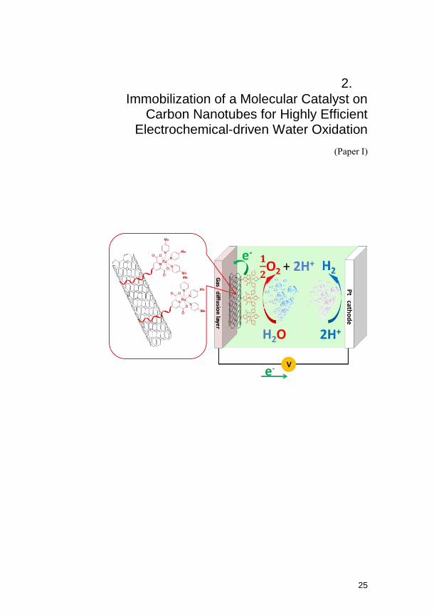
2. Immobilization of a Molecular Catalyst on
Carbon Nanotubes for Highly Efficient Electrochemical-driven Water Oxidation
(Paper I)

26

27
2.1. Introduction
For implementation of any catalysts in electro-driven or light-driven devices
for water splitting, the catalysts have to be immobilized on the surface of
electrodes.123,124
However, challenges in modifying the substrate catalysts and
fabricating into devices hinder the further application of molecular devices,
and therefore, widely applicable approaches and well-designed modification
methods are urgently needed. At the same time, an essential question that
needs to be answered is “How to employ catalysts in functional devices
without affecting their performances?” Previously, our group has reported
two electrodes for electro-driven water oxidation. One is a [Ru(PDC)(pic)3]
modified glassy carbon electrode via click chemistry (as shown in Figure 12).
Only 0.06 mA cm-2
current density was obtained at 700 mV over-potential
while a high TOF of 1.6 s-1
was achieved, which is much higher than the TOF
of 0.23 s–1
evaluated from CeIV
-driven water oxidation.85
Another one is
[Ru(BDA)(Py-pyrene)2] modified multi-walled carbon nanotube (MWCNT)
based electrode through electrostatic π–π stacking interactions (as shown in
Figure 15).125
As [Ru(BDA)] catalyze water oxidation through a bimolecular
radical coupling pathway, immobilization of mononuclear [Ru(BDA)] WOCs
on electrode surface disfavors the bimolecular pathway, resulting in a low TOF
of 0.3 s-1
. However, a high current density of 220 mA cm-2
can be achieved
due to the introduction of MWCNTs which largely increase the surface area of
the electrode. It is interesting to find a immobilization method which can keep
activity of the catalysts and obtain a high performance of electrode at the same
time. Thereby, we designed a mononuclear WOC 15 based on [Ru(PDC)]
which can be immobilized onto carbon nanotubes via hydrophobic interaction,
the prepared electrode [15-MWCNTsCOOH@GDL] was expected to retain
the high activity of catalyst and receive a high efficiency of electrode for water
oxidation.
2.2. Synthesis
The synthetic route of the target complex 15 is shown in Figure 21. First, a
dodecyloxy group was introduced to diethyl 4-hydroxypyridine-2,6-
dicarboxylate by a simple alkylation reaction; after hydrolysis of the ester
group, 4-dodecyloxypyridine-2,6-dicarboxylic acid was obtained. It was then
reacted with cis-[Ru(dmso)4Cl2] in the presence of triethylaimine; 4‒picoline
was then introduced to the solution, giving the target complex 15.

28
Figure 21. Synthesis of complex 15 and the structure of the reference complex 6
2.3. Results and Discussions
2.3.1. Electrochemical properties
0.2 0.4 0.6 0.8 1.0 1.2 1.4 1.6
0.00
0.05
0.10
0.15
0.20
0.25
0.30
0.8 0.9 1.0 1.1 1.2 1.3
0.005
0.010
15
6
BLANK
I (m
A)
Potential V vs. NHE Figure 22. Cyclic voltammograms (CV) of 1 mM 15 (red line) and 6 (blue line) in 0.1M
potassium phosphate buffer (pH 7.0, 10% acetonitrile), with glassy carbon as the
working electrode, Ag/AgCl as the reference electrode, and Pt as the counter electrode.
Scan rate is 100 mV s-1.
To measure the electro-catalytic activity of 15 for water oxidation, cyclic
voltammetry (CV) measurements were conducted. Figure 22 shows CV
curves of 15 and 6 in pH 7.0 phosphate buffer solutions. Complex 15 exhibits
one irreversible RuIII/II
redox peak at E= 0.82 V vs. NHE, indicating the ligand
exchange process of 4‒picoline by water molecule during the redox reaction as
discovered earlier in our group with the reference catalyst 6. An onset potential
of water oxidation was observed around at 1.2 V for 15, which value is very
similar to 6. However, the catalytic current of 15 is higher than that of 6 at

29
potentials beyond 1.4 V, which can be ascribed to: (1) The electron donating
effect of dodecyloxy substituent in 15 is beneficial to accelerate the RDS in the
catalytic cycle. (2) The dodecyloxy chain of 15 is attractive to the surface of
glassy carbon electrode, leading to higher local concentration of 15 than that of
6 at electrode surface.
2.3.2. Preparation of Electrode
Figure 23. The solution of 15 (0.37 mg, 0.0005 mmol) in 10mL water containing 20%
trifluoroethanol (left). MWCNTs-COOH (0.15mg) dispersed in 10ml water containing
20% trifluoroethanol (right), and a mixed solution of 15 (0.37 mg, 0.0005 mmol) and
MWCNTs-COOH (0.15 mg) in 10mL water containing 20% trifluoroethanol (middle).
And SEM image of the surface of [15-MWCNTsCOOH@GDL] electrode.
The catalyst 15 was then immobilized on carboxyl functionalized multi-
walled carbon nanotubes (MWCNTsCOOH). After mixing
MWCNTsCOOH with 15, a colorless solution with precipitation was
observed as shown in Figure 23. This precipitation phenomenon can be
interpreted as follows: (1) because of the hydrophilic carboxyl groups,
MWCNTsCOOH can be dispersed in water; (2) when 15 is immobilized
on the surface of MWCNTsCOOH, the surface of CNTs becomes more
hydrophobic, leading to formation of precipitates. Notably, these
precipitates are the desired electro-catalytic nano-material. They can be
easily collected and applied on conductive substrates for further device
fabrication. In this work, the 15-MWCNTsCOOH precipitates were
collected by filtration through a conductive carbon substrate, so-called
gas diffusion layer (GDL), and a carbon based molecular modified
electrode [15-MWCNTsCOOH@GDL] was then obtained in such a
straight-forward way. The SEM image (Figure 23 right) shows that the
nano-structure of CNTs was well retained and presented a large surface
area after material 15-MWCNTsCOOH was collected by GDL. For
comparison, the pristine [MWCNTsCOOH@GDL] electrode as well as
the [6-MWCNTsCOOH@GDL] electrode was prepared by the same
procedure.

30
2.3.3. Electro-driven Water Oxidation
The surface of [15-MWCNTsCOOH@GDL] is highly hydrophobic, a rotating
disk electrode was employed to get rid of generated oxygen bubbles on the
surface and ensure an effective contact between electrode and electrolyte
during the measurements.
0.2 0.4 0.6 0.8 1.0 1.2 1.4 1.6 1.8
0.0
2.5
5.0
7.5
10.0
12.5
Cu
rre
nt D
en
sity (
mA
cm
-2)
15-MWCNTsCOOH@GDL
6-MWCNTsCOOH@GDL
MWCNTsCOOH@GDL
GDL
Potential (V vs. NHE) Figure 24. CVs of [15-MWCNTsCOOH@GDL] electrode (blue), [6-
MWCNTsCOOH@GDL] electrode (red), without catalyst [MWCNTsCOOH@GDL]
(light blue), only GDL (black). All CV curves taken by using rotating disk electrode
(1000 rpm, 0.2 cm2) as working electrode, Ag/AgCl as the reference electrode, and Pt
as the counter electrode, in aqueous solution (phosphate buffer, pH 7.0, ionic
strength=0.1), with scan rate100 mVs-1.
To determine the stability of the physical attachments between these
components 15, CNTs and GDL, the [15-MWCNTsCOOH@GDL] electrode
was rotated at 1000 rpm for 2 h without applying any potential. CVs before
and after rotation were identical, which suggests a steady and stable
combination among the components of [15-MWCNTsCOOH@GDL].
To measure the electro-catalytic water oxidation activities of theses electrodes,
CV measurements were conducted. The results are shown in Figure 24. When
[MWCNTsCOOH@GDL] was used, no significant catalytic current could be
observed. [6-MWCNTsCOOH@GDL] electrode shows only a slight
enhancement of the catalytic current in comparison to the blank electrode
[MWCNTsCOOH@GDL]. In contrast, a significant enhancement of catalytic
current was observed when [15-MWCNTsCOOH@GDL] was used as working
electrode, which is because of the long hydrophobic aliphatic chain assisted
immobilization of 15 on MWCNTsCOOH. The [15-MWCNTsCOOH@GDL]
electrode exhibits an identical redox waves for the RuIII/II
following an uprising
current at around 1.15 V. The catalytic current density of [15-
MWCNTsCOOH@GDL] is up to 5.6 mA cm-2
at 1.4 V vs. NHE.

31
500 1000 1500 2000 2500 3000 3500
0
1
2
3
4
5
C
urr
en
t D
en
sity (
mA
cm
-2)
time (s)
0 2 4 6 8 10 12 14
0
1
2
3
4
Cu
rre
nt
De
nsity (
mA
cm
-2)
time (h)
Figure 25. Electrolysis of [15-MWCNTsCOOH@GDL] electrode at 1.3V (vs. NHE)
applied potential in 50mM phosphate buffer, pH = 7.0 electrolyte for 1 h (upper) and
15h (lower).
Bulk electrolysis was carried out by applying 1.3 V potential on [15-
MWCNTsCOOH@GDL] for time periods of 1 hour and 15 hours in 50 mM
potassium phosphate buffer (pH = 7.0). The corresponding amount of charge
was recorded. The values of charge were divided by 4F, yielding the
theoretical amounts of O2, which were 4.9 and 31.2 μmol for 1 hour and 15
hours electrolysis, respectively. The real amount of oxygen was calibrated by
GC, resulting 4.7 μmol O2 after 1 hour and 29.0 μmol O2 after 15 hours,
corresponding to Faraday efficiencies of 96% and 93%, respectively. After 15
h electrolysis at a relatively low potential of 1.3 V (vs. NHE), 0.84 mA cm-2
current density was retained. The decay of current density during the bulk
electrolysis suggests the decomposition of the catalyst.
The effective catalyst loading of WOCs (Γ0, mol cm-2
) on the [15-
MWCNTsCOOH@GDL] surface was estimated according to an established
method.126
An average catalyst loading of 8.5 ± 0.4 (10-10
mol cm–2
) was
obtained. This calculated average catalyst loading is far less than the total
amount of 15 used for preparing [15-MWCNTsCOOH@GDL] (0.24 mg cm–

32
2), which is due to that only the outside layer of the hybrid material can contact
with the electrolyte and respond to the CV measurements.
0
.8Q
TOF eqnt F
1 1=4
The electro-catalytic activity of [15-MWCNTsCOOH@GDL] was further
evaluated by chronoamperometric experiments. In typical experiments, the
current was recorded continuously under a sequence of applied potential steps
in the range from 1.12 to 1.32 V (Figure 27 upper). With the assumption of
100% Faraday efficiency, TOFs were calculated according to eqn. 8, where F
is the Faraday constant, Q the integrated charge through the electrode, Γ0 the
effective catalyst loading 8.5 ± 0.4 (10-10
mol cm–2
), t the integration time (30
s), and the number 4 is the equivalent constant because the generation of one
O2 molecule requires the transfer of four electrons.
0 50 100 150 200 250 300
-2
0
2
4
Curr
ent D
ensity (
mA
/cm
2)
time (s)
1.12V1.17V
1.22V
1.27V
1.32V
300 350 400 450 500
0.50
0.75
1.00
1.25
Overpotential (mV)
logT
OF
(s-1
)
3.3s-1
5.1s-1
7.5s-1
10.0s-1
13.7s-1
Figure 26. (upper) Chronoamperometric current densities measured in phosphate
buffer (pH 7.0, IS = 0.1M) under application of a sequential potential steps. (lower)
TOF plot of [15-MWCNTsCOOH@GDL] electrode as a function of overpotential η.
The logarithm of yielded TOFs varies linearly on the applied over-potentials
from 300 to 500 mV(Figure 27 lower). A TOF of 5.1 s–1
was achieved at η =

33
350 mV, and it reaches as high as 13.7 s–1
at η = 500 mV. The calculated initial
TOF is 12.4 s-1
, under the bulk electrolysis conditions at 1.3 V applied
potential. As the resistance losses are included in the measurement, all the
values are underestimated, and the actual TOF values should be bigger than the
given ones.
With the data of Γ0, the average value of TOFs based on the overall TON can
be calculated. Average TOFs of 7.6 s-1
for 1 hour electrolysis, and 3.5 s-1
for
15 hours electrolysis are achieved. The performance of [15-
MWCNTsCOOH@GDL] electrode and different anode electrodes for electro-
catalytic water oxidation from literature are listed in Table 2. [15-
MWCNTsCOOH@GDL] is clearly far superior than other systems in the table
in terms of applied potential, current density, TONs and TOFs.
Table 2. The performance of [15-MWCNTsCOOH@GDL] electrode and different
anode electrodes for electro-catalytic water oxidation from literature reported ones.
Applied
potential
[V vs.NHE]
pH
Current
density
[mAcm-2]
Faraday
efficiency TON TOFa) TOFb)
This work 1h
electrolysis 1.3 7.0 2.2 96% 27647 7.6
12.4
This work 15h
electrolysis 1.3 7.0 0.84 93% 170588 3.5
ITO\MWCNT\
[Ru(BDA)(Py-
pyrene)2] 20h125
1.4 7.0 0.22 96% 11000 0.3
ITO\MWCNT\
polyoxometalate
cluster 127
1.42 7.0 ≈0.2 - - - 0.085
ITO\ [Ru
Mebimpy]
13h89,91,128
1.8 1.0 - >95 % 28000 0.6
ITO\ [Ru
tpy]13h89,91,128 1.8 1.0 0.0067 >95 % 8900 0.3
a). Average TOFs in electrolysis experiments for 1h and 15h; b) the TOF in
chronoamperometric experiments is the initial TOF.
2.5. Summary
In summary, a molecular WOC 15 with dodecyloxy group was successfully
designed and synthesized. Complex 15 was immobilized on MWCNTs
through the hydrophobic interaction to form a hybrid nano-material. This
material was deposited onto GDL by filtration and formed a [15-

34
MWCNTsCOOH@GDL] electrode. This fabricated electrode not only
preserves the water oxidation activity of the molecular catalyst with an
essentially high initial TOF of 12.4 s-1
, but also achieved a surprisingly high
initial catalytic current density of 5.6 mA cm-2
(at 1.3 V applied potential).
This methodology provides a simple and reliable approach of transformation
from a homogeneous catalyst to a functional electrochemical electrode with
retained high activity for water oxidation.

35
3. Control the O‒O bond formation pathway by
immobilizing molecular water oxidation catalysts on the electrode surface
(Paper II)

36

37
3.1. Introduction
In the last chapter, we demonstrated a novel methodology which can keep the
activity of the catalysts and meanwhile obtain a functionalized electrode with a
good performance. Another interesting and important question is “Will the
mechanistic pathway of catalysts change when they are immobilized on the
electrode surface?” To answer this question, we need a methodology
corresponding to the question: “How to get kinetic information of RDS on the
electrode surface?”
Our group has recently developed two series of WOCs [Ru(PDA)L2] and
[Ru(BDA)L2] (PDA2
= 1,10-phenanthroline-2,9-dicarboxylate; BDA2
= 2,2-
bipyridine-6,6-dicarboxylate; L = N-cyclic aromatic ligands),129-134
and these
catalysts show high activities for water oxidation. For [Ru(PDA)] catalysts, O2
is produced via the water nucleophilic attack (WNA) pathway as shown in eqn.
6. In contrast, [Ru(BDA)] WOCs catalyze the oxidation of water through a
radical coupling (RC) pathway as described in eqn. 7. As shown in these two
pathways, for both [Ru(PDA)] and [Ru(BDA)], the OO bond formation are
triggered by RuV=O species. The WNA pathway is a first order reaction for
catalyst while the RC pathway is a second order reaction for catalyst.
Therefore two obvious questions can be raised: (1) is it possible that
[Ru(BDA)] catalysts catalyze water oxidation through the WNA pathway
without sacrificing the high activity of water oxidation if the catalytic centers
are far away from each other? (2) On the contrary, can the [Ru(PDA)] catalysts
go through the RC pathway if the two catalytic centers are close to each other?
The answers to these two questions will not only help us to understand the
mechanisms of molecular catalysts deeply, but also may provide new concepts
for the design of more efficient molecular WOCs. In this chapter, [Ru(PDA)]
and [Ru(BDA)] were chosen as model catalysts, and the electrochemical
polymerization method was used to control the distance of different catalytic
centers by using/without using co-polymer units, with a view to govern the
mechanisms of [Ru(BDA)] and [Ru(PDA)] on the electrode surface.

38
3.2. Design, Synthesis and Preparation of Electrodes
We have designed functional electrodes based on the following analysis:
(1) To force the [Ru(BDA)] catalysts to go through the WNA pathway, one can
prevent two RuV=O units from coupling to each other by immobilizing the
catalyst on electrode materials and meanwhile increasing the distance of the
[Ru(BDA)] units.
(2) To force the [Ru(PDA)] catalysts to go through the RC pathway, linking
[Ru(PDA)] catalysts together via proper organic linkers is a potential method.
In order to control the distance of different catalytic centers, the
electrochemical polymerization method was employed.135,136
Herein, 4-vinyl
pyridine was chosen as the polymerization functional group, and the target
complexes 16 and 17 were synthesized via microwave reactions by heating a
methanol solution containing the corresponding tetra-dentate ligand H2BDA or
H2PDA, cis-Ru(DMSO)4Cl2 and 4-vinyl pyridine in the presence of
triethylamine at 100℃ for 30 min. They were fully characterized by NMR,
elemental analysis and high-resolution MS.
Figure 27. Structures of complexes 16, 17 and schematic diagram of electrodes
prepared via electrochemical polymerization.
By using the method described by Meyer et. al.,137
the glassy carbon working
electrodes were cycled in the solution of 16 or 17 [0.5 mM in complex, 0.1 M
tetra-n-butylammonium hexafluorophosphate (TBAPF6) / acetonitrile] from 0
to -2.4 V (vs. Ag/AgNO3) by cyclic voltammetry. For poly-16+PSt@GC
electrode, the glassy carbon working electrode was cycled in a solution
containing 0.5 mM complex 16, 12.5 mM styrene and 0.1 M TBAPF6 /
acetonitrile from 0 to -2.4 V (vs. Ag/AgNO3) in successive scans. Poly-

39
16@GC and poly-17@GC electrodes were respectively obtained with
dimerization favored configuration. Poly-16+PSt@GC electrode is in
dimerization disfavored configuration, as shown in Figure 27.
3.3. Results and Discussions
3.3.1. CH3CN ligand exchange
Figure 28. 1H-NMR (500 MHz) spectra of (upper) 16 in CD3OD, (lower) 16 in
CD3OD/CD3CN (3:1).
Due to the C2V symmetry of complex 16, the BDA unit renders two doublets
(8.07 and 8.64 ppm) and one triplet (7.93 ppm) in d4-methanol. These three
peaks split into four peaks as shown in Figure 28, when d3-acetonitrile/d4-
methanol are employed as the solvent, which indicates that CH3CN can
coordinate to the Ru center at the same time one carboxylic acid of the BDA
ligand de-coordinates from the Ru center. A similar phenomenon was also
observed for complex 17, which are in agreement with our previous studies on
[Ru(BDA)] and [Ru(PDA)] catalysts with 4-picoline as the axial
ligand.133,134,138
When the electrochemical polymerization experiments are conducted in
acetonitrile containing solutions, acetonitrile-coordinating electrodes (poly-16-
NCCH3@GC) can be obtained. Thereby, we have prepared the polymerized
materials of 16 in two different solvents, acetonitrile and chloroform, resulting
in the corresponding poly-16-NCCH3@GC and poly-16@GC electrodes,
respectively. Their differential pulse voltammograms (DPVs) in pH 7.0
phosphate buffer solutions are depicted in Figure 29. The poly-16-
NCCH3@GC electrode displayed a higher potential of RuIII/II
(0.68 V vs. NHE)
than that of the poly-16@GC electrode (0.64 V vs. NHE). This result is in
agreement with the coordination of CH3CN to the [Ru(BDA)] center for the
poly-16-NCCH3@GC electrode.133,134,138
After the poly-16-NCCH3@GC
electrode was scanned from 0 and 1.6 V in the pH 7.0 phosphate buffer where
water oxidation happened, the original peak of RuIII/II
at 0.68 V disappeared
and a new peak emerged at 0.64 V; this phenomenon indicates that CH3CN can

40
be removed from poly-16-NCCH3@GC after an anodic scan. As chloroform
itself can easily generate radicals which may influence the distance control, in
this work, all the CV and PDV data were obtained by using the electrodes
prepared from acetonitrile via one anodic scan.
0.5 0.6 0.7 0.8 0.9 1.0 1.1Potential V vs. NHE
poly-16@GC obtained from CHCl3
poly-16@GC obtained from CH3CN (first scan)
poly-16@GC obtained from CH3CN (second scan)
Cu
rre
nt
1A
Figure 29. DPV curves of poly-16@GC electrodes prepared from different solvents
(acetonitrile and chloroform). Conditions: 50 mM pH 7.0 phosphate buffer solution;
scan rate 50 mV s−1.
3.3.2. pH Dependent Electrochemistry
The DPVs of poly-16@GC and poly-16+PSt@GC at various pH were
recorded, and the pourbaix diagrams were then constructed as displayed in
Figure 30. These two electrodes show similar pH-dependent redox properties.
The RuIII/II
couple is pH independent below pH 6 and becomes a proton-
coupled electron transfer (PCET) process in the region of pH 611; the latter is
ascribed as RuIII
-OH/RuII-OH2. Thereby, the pKa of Ru
III-OH2 is 6.
For RuIV/III
, a one-electron-one-proton PCET process can be observed over the
whole pH range from 2 to 11, corresponding to either RuIV
-OH/RuIII
-OH2 or
RuIV
=O/RuIII
-OH.
The oxidation of RuIV
=O only involves electron transfer at pH > 6, while
oxidation of RuIV
-OH is accompanied by a proton transfer below pH < 6.
The Pourbaix diagrams of poly-16@GC and poly-16+PSt@GC reveal that the
three oxidation peaks at pH 7 correspond to RuIII
-OH/RuII-OH2, Ru
IV=O/Ru
III-
OH and RuV=O/Ru
IV=O, respectively, and the OO bond formation are
triggered by RuV=O species for both electrodes, which is the foundation of this
work as we mentioned in the introduction of this chapter.

41
2 3 4 5 6 7 8 9 10 11
0.4
0.6
0.8
1.0
1.2
1.4
RuV-O or Ru
IV-O
RuIV
-OH
RuIV
-O
RuIII
-OH
RuII-OH2
Po
ten
tia
l V
vs
. N
HE
pH
RuIII
-OH2
2 3 4 5 6 7 8 9 10 11
0.4
0.6
0.8
1.0
1.2
1.4
pH
Po
ten
tia
l V
vs
. N
HE
RuII-OH2
RuV-O or Ru
IV-O
RuIV
-OH
RuIII
-OH2
RuIII
-OH
RuIV
-O
Figure 30. Pourbaix diagrams of poly-16@GC (upper) and poly-16+PSt@GC (lower).
3.3.3. Methods for Electrode Kinetics
The electrode kinetic study is a challenging task and very different with
homogeneous kinetic studies; the current method for electrode mechanistic
study mainly depends on time-resolved spectroscopy (electrochemistry, IR,
Raman, XPS). Very few reports can provide a clear evidence of the mechanism
about OO bond formation on electrode surface, and there is no report about
molecular WOCs which can go through RC pathway on electrode surface. In
this work, we focus on the difference of the OO bond formation between
WNA and RC pathways and provide a method for the catalytic OO bond
formation study on the functionalized electrode surface.
From eqn. 6 and 7 we can find two key differences between WNA and RC
pathways:
1) Reaction order for the O-O bond formation. The O-O bond formation is first
order in catalyst for the WNA pathway and becomes second order in catalyst
for the RC pathway.

42
2) Proton transfer. The proton transfer process is involved for the WNA step,
but not the case for the RC step, which can be reflected by kinetic isotope
effects (KIEs). At the same time, base as a proton acceptor can decrease the
barrier in the O‒O bond formation step for the WNA pathway which means
base is involved for the WNA pathway, but not the case for RC pathway.
According to the above analysis, to study the mechanistic pathways of poly-
16@GC, poly-16+PSt@GC and poly-17@GC electrodes, reaction orders and
KIEs should be examined. The reaction order is an empirical factor widely
used in chemical kinetic studies, which can give an insight into the events at
the molecular level for kinetics of complex reactions.139
log
log. 9
ii
k i
j
ceq
cn
In electrode kinetics, the reaction order (ρi) of species at concentration ci can
be determined from electro-kinetic measurements when the concentration of
all other species (ck≠i) are held constant, and is given by eqn. 9,139,140
where j is
a partial anodic current corresponding in our case to the catalytic current (mA),
and 𝑐𝑖 is the concentration of species (mol L-1
).
Consider that Γ (catalyst coverage mol cm-2
) can be accounted as the
concentration of catalyst on the electrode. And Γ has the linear relationship
with the peak current ip (here is the redox peak of RuII/III
) given by eqn. 10,126
where np is number of electrons (here for RuIII/II
np is 1), ν scan rate (V s-1
), A
surface area (cm2), F Faraday‟s constant (96485 C mol
−1), R ideal gas constant
(8.314 JK–1
mol–1
) and T temperature (298 K).
/
2 2
( ) .104
III IIp
p Ru eqnn F A
RTi
By combining eqn.9 and 10, the reaction order of catalyst coverage ρΓ can be
given by eqn. 11. To obtain ρΓ, only catalytic currents j and peak current ip of
RuII/III
are needed, which can be easily obtained by CV measurements.
log
log. 11
p
j
ieqn
The KIE values reflect the kinetic information of water oxidation reactions and
help us to interpret the rate determining step (RDS) of the catalytic
processes.141-144
The presence of KIE is considered as evidence that proton
transfer is involved in the RDS (or, at least, in one of the steps affecting the
reaction rate). At the same time, absence of KIE is widely accepted as a line of
evidence for the RDS not involving the proton transfer.145
The KIE for water
oxidation catalytic reactions can be divided into two kinds on the basis of
different reaction mechanisms and RDSs:

43
(1) When the RDS is the water nucleophilic attack process (eqn. 6), the OH
bond cleavage is involved, the reaction shows a primary isotope effect, and the
value of KIEH/D is usually more than 2.141-144
(2) When the RDS is the dimerization of two RuV=O units (eqn. 7), no such
OH bond cleavage is then involved, and the reaction will show a secondary
isotope effect in which the value of KIEH/D is usually between 0.7 and
1.5.27,138,146
By combining the reaction order and kinetic isotope effect, the kinetic
information and mechanistic pathways should be realistically reflected.
3.3.4. The O‒O Bond Formation Pathways on Electrodes
Firstly, the poly-16@GC electrode was examined. By controlling the time of
polymerization or scan numbers of CV experiments, poly-16@GC electrodes
with various Γ were obtained. As shown in Figure 31A, the anodic current
increased with the increase of Γ under the same conditions. According to eqn.
11, the reaction orders ρΓ of poly-16@GC at various Γ are calculated to be
around 2 at different applied potentials. This value indicates that water
oxidation catalyzed by poly-16@GC is a second order reaction in catalyst
[Ru(BDA)] and reveals a RC pathway for the O-O bond formation.
The reaction order of phosphate was also examined. As the analysis for the
WNA pathway before, atom–proton transfer (APT) with base (B) as a proton
acceptor can decrease the barrier in the O‒O bond formation step as shown in
eqn. 12, which means that base such as phosphate is usually involved in the
WNA process.147,148
By keeping the catalyst coverage Γ and other parameters
constant and only changing the concentration of phosphate buffer (Na2SO4 salt
is added to maintain the ionic strength to be 0.1 M), the reaction orders of
phosphate (ρpi) are calculated (Figure 31B) according to eqn. 9, giving a ρpi= 0
for poly-16@GC which means that phosphate is not involved in the RDS. This
is also in a good agreement with that poly-16@GC catalyzes water oxidation
through the RC pathway.
KIEs can reflect the kinetic information of the RDS. Here, we controlled the
catalyst coverage Γ of poly-16@GC and other parameters, changed the
phosphate buffer to 50 mM Na2SO4 H2O or D2O solutions. CV curves of poly-
16@GC in H2O and D2O were compared (Figure 31C). A secondary isotope
effect was observed as evidenced by the KIE(H/D) values less than 1.5 in the
range of 1.1 V to 1.4 V, suggesting that the O-H bond cleavage is not involved

44
in the RDS by using poly-16@GC electrode. According to ρΓ, ρpi and KIE data,
we can conclude that poly-16@GC goes through the RC pathway.
0.2 0.4 0.6 0.8 1.0 1.2 1.4 1.6
0.0
0.3
0.6
0.9
1.2
1.2V vs. NHE
1.3V vs. NHE
1.4V vs. NHE
1.5V vs. NHE
-3.60 -3.55 -3.50 -3.45 -3.40
-2.4
-2.0
-1.6
-1.2
log(ip of RuII/Ru
III mA)
log
j (m
A )
y = a + b*x Value R^2
Slope 1.2V 1.86 0.986
Slope 1.3V 1.97 0.951
Slope 1.4V 1.95 0.977
Slope 1.5V 1.91 0.961
Potential V vs. NHECu
rre
nt
De
ns
ity
(m
A c
m-2
)
A
loa
din
g in
cre
as
e
50mM
100mM
200mM
300mM
0.2 0.4 0.6 0.8 1.0 1.2 1.4 1.6
0.0
0.6
1.2
1.8
2.4
3.0
-1.25 -1.00 -0.75 -0.50-3
-2
-1
0
log [Pi] (m ol L-1)
log
j (
mA
)
1.2V vs. NHE
1.3V vs. NHE
1.4V vs. NHE
y = a + b*x
Slope 1.4V 0.011
Slope 1.3V -0.043
Slope 1.2V 0.107
Potential V vs. NHE
Cu
rre
nt
De
ns
ity
(m
A c
m-2
)
B
0.2 0.4 0.6 0.8 1.0 1.2 1.4 1.6
0.0
0.1
0.2
0.3
0.4
1.1 1.2 1.3 1.4 1.50.0
0.5
1.0
1.5
2.0
Potential V vs. NHE
KIE
( j
H2
O /
j D
2O
)
Potential V vs. NHE
Cu
rren
t D
en
sit
y (
mA
cm
-2)
poly-16 in H2O
poly-16 in D2O
C
Figure 31. (A) CVs of poly-16@GC at various catalyst coverage Γ. Inset is the plot of
log (j) versus log (iRuIII/II); the slopes of the linear fitting curves reflect the reaction
orders in catalyst coverage. (B) CVs of poly-16@GC at various phosphate buffer
concentration [Pi]. Inset is the plot of log (i) versus log ([Pi]); the slopes of the linear
fitting curves reflect the reaction orders in [Pi]. (C) CVs of poly-16@GC in D2O and
H2O (electrolyte = Na2SO4; 50 mM). Inset shows the KIE values versus E.

45
0.2 0.4 0.6 0.8 1.0 1.2 1.4 1.6
0.0
0.3
0.6
0.9
1.2
1.5
1.3V vs. NHE
1.4V vs. NHE
1.5V vs. NHE
1.6V vs. NHE
-4.2 -4.1 -4.0 -3.9 -3.8 -3.7 -3.6
-2.4
-2.0
-1.6
-1.2
log
j (
mA
)
logip of RuII
/RuIII
(mA)
�
y = a + b*x Value R^2
slope 1.3V 1.12 0.976
slope 1.4V 1.18 0.922
slope 1.5V 1.31 0.984
slope 1.6V 1.29 0.991
Potential V vs. NHE
Cu
rre
nt
de
ns
ity
(m
A c
m-2
)
load
ing
incre
ase
A
0.2 0.4 0.6 0.8 1.0 1.2 1.4 1.6
0.0
0.2
0.4
0.6
0.8
-1.4 -1.2 -1.0 -0.8 -0.6 -0.4
-2.0
-1.8
-1.6
-1.4
-1.2
lo
g j
(m
A)
1.6V vs.NHE
1.5V vs.NHE
1.4V vs.NHE
�
y = a + b*x
Slope 1.3V 0.174
Slope 1.4V 0.196Slope 1.5V 0.212
Slope 1.6V 0.222
1.3V vs.NHE
log [Pi] mol L-1
Potential V vs. NHE
50mM
100mM
200mM
300mM
Cu
rre
nt
de
ns
ity
(m
A c
m-2
)
B
0.2 0.4 0.6 0.8 1.0 1.2 1.4 1.6
0.0
0.1
0.2
1.1 1 .2 1 .3 1 .4 1 .50 .0
0 .5
1 .0
1 .5
2 .0
2 .5
KIE
(
j H2
O /
j D2
O )
P o ten tia l V vs. N H E
poly 16+PSt in H2O
poly 16+PSt in D2O
Potential V vs. NHE
Cu
rre
nt
De
ns
ity
(m
A c
m-2
)
C
Figure 32. (A) CVs of poly-16+PSt@GC at various catalyst coverage Γ. Inset is the
plot of log (j) versus log (iRuIII/II); the slopes of the linear fitting curves reflect the reaction
orders in catalyst coverage. (B) CVs of poly-16+PSt @GC at various phosphate buffer
concentration [Pi]. Inset is the plot of log (i) versus log ([Pi]); the slopes of the linear
fitting curves reflect the reaction orders in [Pi]. (C) CVs of poly-16+PSt @GC in D2O
and H2O (electrolyte = Na2SO4; 50 mM). Inset shows the KIE values versus E.
Next, the poly-16+PSt@GC electrodes were prepared by co-polymerizing 1-
equivalent catalyst 16 and 25-equivalent styrene on the glassy carbon

46
electrode. As shown in Figure 27, the catalytic centers of poly-16+PSt@GC
are considered to be far away to each other because poly-styrene (PSt)
blocking units were added to separate the catalyst units.
The kinetics of poly-16+PSt@GC was examined by using the same method as
above. As shown in Figure 32, ρΓ of poly-16+PSt@GC was calculated to be
1.2, ρpi is 0.2 and KIEs(H/D) is 2 at 1.4 V vs. NHE. The value of ρΓ (1<ρΓ<2)
indicates that poly-16+PSt@GC oxidizes water through both WNA and RC
pathways with the former WNA pathway as the dominating one. This is
because that a small amount of catalytic centers in a short distance in still have
chance to meet each other the polymer, resulting in mixed pathways for poly-
16+PSt@GC.
Since the WNA pathway is dominating, the value of ρpi was observed to be
0.2. In comparison with the ρpi of poly-16@GC (ρpi = 0), the value of ρpi = 0.2
clearly revealed that phosphate is involved in the RDS for poly-16+PSt@GC,
indicating that the atom–proton transfer process occurs. At the same time,
KIE(H/D) values of poly-16+PSt@GC show a primary isotope effect, and
thereby the OH bond cleavage is involved in the RDS. In consideration of ρΓ,
ρpi and KIE, poly-16+PSt@GC mainly goes through the WNA pathway.
Clearly, the WNA pathway is favored for water oxidation when catalytic
centers are far away to each other.
1.2 1.3 1.4 1.5 1.6
0
2
4
6
8
10
12
14
poly-16@GC
poly-16+PSt@GC
TO
F (
s-1)
Potential (V vs. NHE)
Figure 33. Plot of TOFs versus potential.(●) poly-16@GC; (▲) poly-16+PSt@GC.
TOFs were calculated according to eqn.8 in chapter 1.
Turnover frequencies (TOFs) of poly-16@GC and poly-16+PSt@GC were
compared (Figure 33). At similar catalyst coverage (1.2×10⁻¹¹
mol cm–2
for
poly-16@GC and 1.8×10⁻¹¹
mol cm–2
for poly-16+PSt@GC), poly-16@GC
shows much higher TOF than that of poly-16+PSt@GC at the same applied
potential. For example, poly-16@GC gives a TOF of 11.2 s-1
at 1.5 V vs. NHE
while poly-16+PSt@GC just shows a TOF of 3.9 s-1
. Accordingly, the
[Ru(BDA)] catalyst on the electrode surface catalyzes water oxidation more
effectively via the RC pathway than the WNA pathway

47
10 20 30 40 50
0.001
0.002
0.003
0.004
0.005
0.006
0.007
Cu
rre
nt
De
nsity (
mA
cm
-2)
Time (s)
Figure 34. Chronocoulometry of poly-17@GC with different catalyst coverage.
In contrast with [Ru(BDA)] catalysts, we have earlier shown that the
[Ru(PDA)] water oxidation catalysts catalyze CeIV
-driven water oxidation via
the WNA path in homogeneous system.133
The OO bond formation energy
barriers for a [Ru(PDA)] catalyst were calculated to be 13.3 kcal mol-1
via the
WNA pathway and 16.4 kcal mol-1
via the RC pathway. The energetic
difference between these two processes is only 3.1 kcal mol-1
. Will the
[Ru(PDA)] catalyst change the O-O bond formation mechanism from the
WNA pathway to the RC pathway if the [Ru(PDA)] units are enforced close to
each other? Can we really make the energy barrier for the RC pathway less
than that of the WNA pathway through the electro-polymerization method?
To address these questions, catalyst 17 was polymerized on glassy carbon by
the same method as for poly-16@GC, resulting in the poly-17@GC electrode.
As the RuII/III
peak of catalyst 17 is not reversible, eqn. 10 is not suitable for
poly-17@GC electrodes. While the catalyst coverage Γ can also be calculated
by eqn. 13,149
where Q is the integrated current under the RuIII/II
of poly-17, F
Faraday‟s constant (96485 C mol−1
), n the number of electrons transferred (n =
1), and A the area of the electrode (~ 0.07 cm2).
.13Q
nFAeqn
Then the corresponding ρΓ can be calculated by eqn. 14.
log
log.14
jeqn
To calculate the catalyst coverage Γ, chronocoulometry of poly-17@GC was
operated in 50 mM potassium phosphate buffer pH 7.0. To exclude the effect
of capacitance, first, 0.6V vs. NHE potential were added to working electrodes
for 10s, then 0.85V vs. NHE potential were added to the working electrodes
for 50s, and the current densities were recorded as shown in Figure 34.

48
0.2 0.4 0.6 0.8 1.0 1.2 1.4 1.6
0.00
0.25
0.50
0.75
-9.35 -9.30 -9.25 -9.20-2.0
-1.8
-1.6
-1.4
1.6V vs. NHE
1.5V vs. NHE
log mol cm-2
log j
(m
A)
y = a + b*x value R^2
Slope 1.45V 1.98 0.95
Slope 1.5V 1.98 0.94
Slope 1.6V 1.92 0.91
1.45V vs. NHE
Potential (V vs. NHE)
Cu
rre
nt
de
ns
ity
(m
A c
m-2
)
load
ing
incre
as
e
A
0.2 0.4 0.6 0.8 1.0 1.2 1.4 1.6
0.0
0.5
1.0
1.5
2.0
-1.4 -1.2 -1.0 -0.8 -0.6 -0.4
-5.0
-4.5
-4.0
-3.5
-3.0
l
og
j (m
A)
log [Pi] mol L-1
1.3V vs. NHE
1.4V vs. NHE
1.5V vs. NHE
y = a + b*x
1.3V Slope -3.4364E-4
1.4V Slope 0.02456
1.5V Slope 0.0342
1.6V Slope 0.06551.6V vs. NHE
50mM
100mM
200mM
300mM
Potential V vs. NHE
Cu
rre
nt
de
ns
ity
(m
A c
m-2
)
B
0.2 0.4 0.6 0.8 1.0 1.2 1.4 1.6
0.0
0.1
0.2
0.3
0.4
0.5
1.0 1.2 1.4 1.60.0
0.5
1.0
1.5
2.0
Potential V vs. NHE
KIE
(j
H2
O /
j D
2O
)
Potential V vs. NHE
poly-17 in H2O
poly-17 in D2O
Cu
rren
t d
en
sit
y (
mA
cm
-2)
C
Figure 35 (A) CVs of poly-17@GC at various catalyst coverage Γ. Inset is the plot of
log (j) versus log (Γ); the slopes of the linear fitting curves reflect the reaction orders in
catalyst coverage. (B) CVs of poly-17@GC at various phosphate buffer concentration
[Pi]. Inset is the plot of log (i) versus log ([Pi]); the slopes of the linear fitting curves
reflect the reaction orders in [Pi]. (C) CVs of poly-17@GC in D2O and H2O
(electrolyte = Na2SO4; 50 mM). Inset shows the KIE values versus E.
Poly-17@GC electrodes were examined by the same methods. As shown in
Figure 35, ρΓ of poly-17@GC is calculated to be around 1.9, ρpi is 0 and
KIE(H/D) is around 1.1. These three values suggest that poly-17@GC goes
through the RC pathway. The RC pathway is favored when catalytic centers
are close to each other, like the case of polymerization of [Ru(PDA)] on

49
electrode surface, although the [Ru(PDA)] catalyst itself favors the WNA
pathway in the homogeneous system. This is the first example clearly showing
that we can switch the mechanisms of a catalyst from the WNA to the RC
through catalyst engineering.
3.4. Summary
In summary, molecular WOCs 16 and 17 with 4-vinyl pyridine as axial ligands
were successfully polymerized on glassy carbon electrodes, and the resulting
poly-16@GC and poly-17@GC electrodes were obtained. By co-polymerizing
catalyst 16 with styrene, poly-16+PSt@GC electrode was also prepared. The
reaction orders in catalyst and phosphate as well as the kinetic isotope effects
for electrochemical water oxidation were examined. Both poly-16@GC and
poly-17@GC electrodes catalyze the electrochemical water oxidation reaction
through the radical coupling (RC) pathway, even water nucleophilic attack
pathway is dominated for catalyst 17 in the homogenous system. On the
contrary, the poly-16+PSt@GC electrode with styrene as blocking units favors
the WNA pathway. Comparing the TOFs of poly-16@GC with poly-
16+PSt@GC, the RC pathway shows a faster reaction rate than that of the
WNA pathway. These results provide guidance for controlling the reaction
mechanism of molecular water oxidation catalysts on the electrode surface.
Our work provides solid evidences for understanding the reaction mechanisms
of water oxidation catalysts on the electrode surface.

50

51
4. Immobilizing Ru catalysts on photoanodes for light-driven water splitting
(Paper III and IV)

52

53
4.1. Introduction
In the last two chapters, we have discussed anodes for electro-driven water
oxidation, which are related to the indirect approach for solar fuel conversion.
In the following two chapters, we will discuss the PEC cells for direct solar
fuel conversion.
Recently, our group has published a series of photoanodes based on [Ru(BDA)]
catalysts. We had constructed a photoanode in which the [Ru(BDA)] catatlyst
was encapsulated in the Nafion film covered onto a Ru dye-sensitized TiO2
film and achieved light-driven water splitting.150
Later on, phosphonic acid and
silane groups, were introduced on [Ru(BDA)] catalysts as anchoring groups for
the attachment of [Ru(BDA)] catalysts on the Ru dye -sensitized TiO2 films via
chemical bonds.104,151
The resulting photoanode gave significant high
photocurrent density for water splitting. Since the [Ru(BDA)] WOCs catalyze
water oxidation via a bimolecular reaction mechanism and the rate determining
step of the catalytic cycle is the dimerization of two RuV=O species,
131
immobilization of mononuclear [Ru(BDA)] WOCs on the electrode surface
disfavors the bimolecular pathway. Accordingly, we synthesized a dimer
molecular [Ru(BDA)] catalyst with an anchoring group and co-adsorbed it on
the TiO2 film together with Ru dye, achieving an enhanced photoanode
performance.105
In the last chapter, we have studied the O-O bond formation mechanistic
pathways on electrodes prepared via electrochemical polymerization method.
As the RC pathway shows a faster reaction rate than that of the WNA pathway,
we would like to use poly-16 on photoanodes for light-driven water oxidation
in this chapter. We will try to find the reason(s) for the fast photo-current decay
through kinetic studies. Further, we will give a solution about “How to
improve the stability of photoanodes?”

54
4.2. Synthesis and Preparation of Electrodes
Figure 36. The chemical structures of complexes 16, 18 and RuP.
The catalyst 16 was prepared by the method as described in the last
chapter. For comparison, catalyst 18 was also prepared by a simple
reaction as shown in Figure 37. To prepare the photoanode, TiO2 films
were prepared according to our previous report.151
Figure 37. Synthesis route of complex 18
Briefly, 18 nm anatase TiO2 paste was screen-printed on FTO glass, then
annealed at 500 ºC for 30 min. The thickness of obtained bare TiO2 film
is ca. 8 μm. The active areas of the photoelectrodes were 1 cm2.
18+RuP@TiO2 electrodes were prepared according to our previous
work.151
Poly-16+RuP@TiO2 electrodes were prepared as follows:
complex 16 was polymerized on RuP sensitized TiO2 films by
electrolysis of a complex 16 solution (1 mM in 100 mM
TBAPF6/acetonitrile solution) at 2.0 V (vs Ag/AgNO3) for 200 seconds.
All of the tests were operated under 300 mW cm-2
of light density.

55
4.3. Results and Discussions
4.3.1. Electrochemical Properties
After the polymerization of catalyst 16 on RuP@TiO2, the prepared poly-
16+RuP@TiO2 electrode showed an orange color (Figure 38 inset), while the
RuP@TiO2 electrode showed a light yellow color. The difference in colors
indicates the formation of the catalyst polymer in the case of poly-
16+RuP@TiO2 electrode.
0.4 0.6 0.8 1.0 1.2 1.4 1.6
0.0
0.2
0.4
0.6
0.8
0.4 0.6 0.8 1.0 1.2
0
5
10
15
Potential(vs. NHE)
Cu
rre
nt
A
poly-16@TiO2
Potential V vs. NHE
Curr
ent
(mA
)
poly-16+RuP@TiO2
RuP@TiO2
Figure 38. Upper, CV curves of poly-16+RuP@TiO2(red line), 18+RuP@TiO2(blue
line) and RuP@TiO2(black line). Lower, DPV curves of poly-16+RuP@TiO2(red line)
and RuP@TiO2(blue line) and inset poly-16@TiO2.
From cyclic voltammogram (Figure 38 upper), 18+RuP@TiO2 electrode
displays a redox peak of RuII/Ru
III at 0.65 V vs. NHE followed by a catalytic
wave with an onset potential Eonset = 1.1 V vs. NHE. For that of poly-
16+RuP@TiO2 a clearly redox peak of RuII/Ru
III can be observed at 0.70 V vs.
NHE, followed by a catalytic wave with an Eonset = 1.15 V. Besides the
RuII/Ru
III peak at 0.65 V, the PDV (Figure 38 lower) of the poly-
16+RuP@TiO2 electrode exhibits RuII/Ru
III peak at 0.70 V and Ru
III/Ru
IV peak

56
at 0.89 V, following a RuII/Ru
III peak of RuP overlapping with Ru
IV/Ru
V(1.1V)
peak of [Ru(BDA)]. The DPV of 18+RuP@TiO2 electrode is similar with our
previous work.151
These electrochemical results indicate that
thermodynamically, a photo-generated RuIII
P can oxidize [Ru(BDA)] from
RuII to Ru
III–H2O, Ru
IV–OH and even till Ru
V=O species.
4.3.2. Photo-Electrochemistry
A 3-E PEC cell was set up with the photoanode poly-16+RuP@TiO2 as
working electrode, Ag/AgCl as reference electrode and Pt net as counter
electrode. First, LSV experiments were carried out as shown in Figure 39. For
poly-16+RuP@TiO2 under light illumination, the photocurrent rapidly
increased with the rise of applied potential from -0.25 V to 0.20 V (vs. NHE).
The photocurrent reached a plateau at E > 0.20 V with a photocurrent density
of 1.4 mA cm-2
, which is in agreement with our earlier reported results.104,151
The LSV of 18+RuP@TiO2 electrode is similar with our previous work.151
-0.25 0.00 0.25 0.50 0.75 1.00 1.25-0.5
0.0
0.5
1.0
1.5
2.0
2.5
3.0
Potential V vs. NHE
Curr
ent
Density (
mA
cm
-2)
poly-16+RuP@TiO2 Light
poly-16+RuP@TiO2 Dark
Figure 39. LSV measurements of the WEs under light illumination through a 400 nm
long-pass filter (light intensity 300 mW cm-2), scan rate= 50 mV s-1
The photocurrent of the photoanode under a bias potential of 0.2 V vs. NHE
was measured. A remarkable initial photocurrent density of about 3.0 mA·cm−2
was obtained for the poly-16+RuP@TiO2 photoanode, while for the
RuP@TiO2 photoanode, no significant photocurrent could be observed.
However, the photocurrent of the poly-16+RuP@TiO2 photoanode is unstable
with time. As shown in Figure 40, the photocurrent density decreased from 3
to 0.3 mA cm-2
after 200 seconds. For 18+RuP@TiO2, the photocurrent
density decreased even faster. This instability problem is a general problem for
all developed photo-active electrodes at the moment.104,105,151
Improvement of
the long time durability of photo-electrodes is urgently needed for the further
applications of this type device.

57
0 100 200 300 400 500
0.0
0.5
1.0
1.5
2.0
2.5
3.0
3.5
poly-16+RuP@TiO2
18+RuP@TiO2
RuP@TiO2
time (s)
Cu
rre
nt
de
nsity (
mA
cm
-2)
Figure 40. The full time photocurrent of illumination on photoanodes under an applied
potential of 0.2 V vs. NHE in the PEC, operated in a 50 mM pH 7.0 phosphate buffer
solution.
4.3.3. Kinetics Study
Kinetic information may help us to find the reason of the fast photo-current
decay. Kinetic isotope effects (KIEs) of poly-16+RuP@TiO2 and
18+RuP@TiO2 were studied to reveal the RDS of our photoanodes during the
catalytic processes. KIE reflects the kinetic information of water oxidation
reactions as we have introduced in the last chapter.
Firstly, the electro-catalytic KIEs of poly-16+RuP@TiO2 and 18+RuP@TiO2
electrodes were compared under dark conditions in order to exclude the effect
of photo-induced electron transfer. Chronoamperometric experiments were
conducted in both H2O and D2O solutions with 100 mM Na2SO4 as supporting
electrolyte. Upon applying potentials on poly-16+RuP@TiO2, the current
densities showed negligible difference between H2O and D2O solutions. The
KIEH/D value was calculated as ca. 1.1 (Figure 41 upper).
Under the same conditions, the 18+RuP@TiO2 electrode shows a KIEH/D of
ca.1.9, which is significantly different from that of poly-16+RuP@TiO2.
Accordingly, poly-16+RuP@TiO2 has a secondary isotope effect and the
18+RuP@TiO2 electrode has a primary isotope effect. Therefore poly-16 was
proposed to catalyze water oxidation through the RC pathway, and in contrast,
complex 18 was proposed to catalyze water oxidation via the WNA pathway or
mixed pathways. The results obtained here are in agreement with the
conclusion from last chapter. The distance between catalytic centers will affect
the mechanism of water oxidation.

58
0 50 100 150 200 250
0.0
0.5
1.0
1.5
2.0
2.5
1.5V
time (s)
Cu
rre
nt
den
sit
y (
mA
cm
-2)
poly-16+RuP@TiO2 in H2O
poly-16+RuP@TiO2 in D2O
1.2V
1.3V
1.1V
1.4V
a
0 50 100 150 200 250
0.0
0.5
1.0
1.5
time (s)
Cu
rre
nt
de
ns
ity
(m
A c
m-2)
18+RuP@TiO2 in H
2O
18+RuP@TiO2 in D
2O
1.1V
1.2V
1.3V 1.4V
1.5V
30 40 50 60 70
0.0
0.3
0.6
0.9
Cu
rre
nt
den
sit
y (
mA
cm
-2)
time (s)
poly-16+RuP@TiO2 in H2O
poly-16+RuP@TiO2 in D2O
80 100 120
-0.2
0.0
0.2
0.4
0.6
0.8
1.0
Cu
rre
nt
De
ns
ity
(m
A c
m-2)
Time (s)
18+RuP@TiO2 in H2O
18+RuP@TiO2 in D2O
Figure 41. (upper). Chronoamperometric current densities measured under application
of a sequential potential steps. (Lower).The transient current responses to on˗off cycles
of illumination on photoanodes under an applied potential of 0.2 V vs. NHE operated in
a 100 mM Na2SO4 H2O and D2O solution.
To study the photocurrent density decay, the KIEs measurements were also
conducted under light illumination as shown in Figure 41 lower. The
photocurrents of either poly-16+RuP@TiO2 or 18+RuP@TiO2 show no clear
difference in H2O and D2O solutions under illumination, which means that the
RDSs for these two electrodes are not related to the O-H bond cleavage for
light-driven water oxidation. This result for 18+RuP@TiO2 seems
contradictory to the KIE = 1.9 under electro-driven conditions. We believe the
water oxidation mechanism of catalyst 18 for light-driven water oxidation still
keeps the same as that under electro-driven conditions, i.e. WNA, but it is not
the rate limiting step for the whole PEC process. In another word, the KIEs of
light-driven water oxidation reflect the RDS of the whole PEC process instead
of the catalytic cycle of catalysts. Since the electron injection from dye into
TiO2 is ultrafast,152
and the catalytic process of catalyst is not the RDS, it
means that the photo-induced electron transfer from catalyst to the oxidized
RuP is not efficient enough as shown in Figure 42. A reasonable explanation
is that the regeneration of RuP becomes the RDS for the whole PEC process
for 18+RuP@TiO2 and the same may be also applicable for poly-
16+RuP@TiO2.

59
Figure 42. Simplified electron flows of catalyst-dye-semiconductor.
In light-driven reactions, the RDS is not the oxidation of water by the catalyst,
which is also observed from other photosystems,153
and the slow regeneration
of RuP can lead to the decomposition/desorption of RuP.154
Therefore,
photocurrent decay under long time light illumination is probably caused by
the decomposition/desorption of dye due to the slow electron transfer from
catalyst to dye+.
4.3.4. Replacement of the Molecular Photosensitizer by α-Fe2O3
Based on the above analysis, there are several strategies which can be used to
improve stability of photo-electrodes during long time illumination. Obviously,
linking catalyst and dye together to improve the electron transport between
them can be a reliable strategy. Related work has been demonstrated by our
group,155
where a [Ru(BDA)] catalyst and a Ru-based dye were linked by Zr4+
ions bridge and a relatively stable photocurrent was obtained. Recently, Meyer
et al. published that the same catalyst 16, propylene carbonate and a Ru-based
dye were copolymerized on TiO2. A low photocurrent of 40 μA cm-2
was
achieved, but a relatively stable photocurrent can be obtained.137
These two
works support that enhancing the electron transport between catalyst and
photosensitizer will increase the stability of this type of PEC device.
Combining with our kinetic study in this work, we have proved that the fast
electron transfer is beneficial for the stability of the device.
Another more straightforward strategy can be also proposed intuitively, which
is replacing RuP by a more stable photosensitizer. Here we would like to
demonstrate our efforts on replacing RuP@TiO2 by an α-Fe2O3 nano-rod array
in order to get a stable photocurrent.
The α-Fe2O3 nano-rod array serves as the photosensitizer and semiconductor.
Again, catalyst 16 was electrochemically polymerized on the Fe2O3 nano-rod
electrodes. An experiment of transient current responses to on˗off cycles of
light on poly-16@Fe2O3 electrode under an external bias of 0.6 V vs. NHE was
then performed as shown in Figure 43. An initial photocurrent density of 600
μA cm−2
was obtained by using the poly-16@Fe2O3 photoanode. In
comparison, the bare α-Fe2O3 nano-rod electrode yielded an initial
photocurrent density of 300 µA·cm−2
. For long time light illumination, a
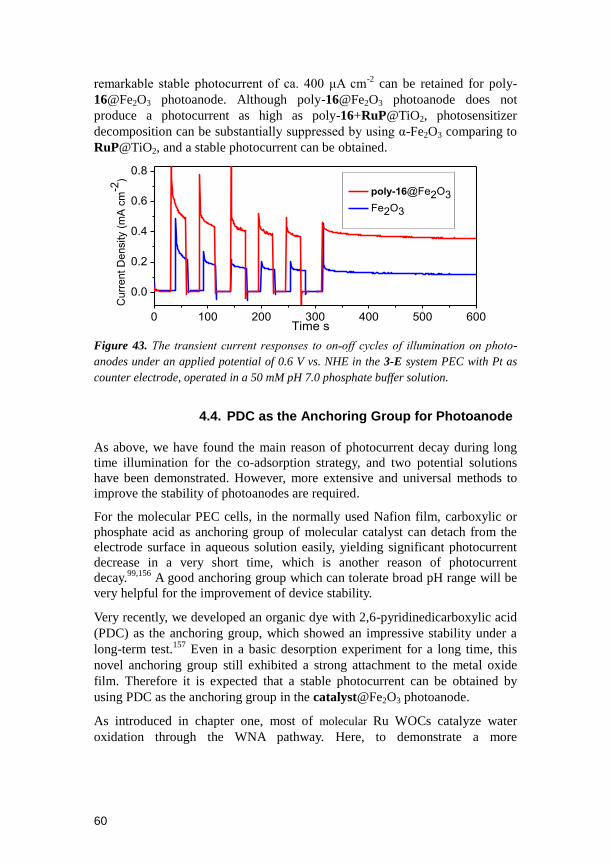
60
remarkable stable photocurrent of ca. 400 μA cm-2
can be retained for poly-
16@Fe2O3 photoanode. Although poly-16@Fe2O3 photoanode does not
produce a photocurrent as high as poly-16+RuP@TiO2, photosensitizer
decomposition can be substantially suppressed by using α-Fe2O3 comparing to
RuP@TiO2, and a stable photocurrent can be obtained.
0 100 200 300 400 500 600
0.0
0.2
0.4
0.6
0.8
Time s
Cu
rre
nt
De
nsity (
mA
cm
-2)
poly-16@Fe2O3
Fe2O3
Figure 43. The transient current responses to on˗off cycles of illumination on photo-
anodes under an applied potential of 0.6 V vs. NHE in the 3-E system PEC with Pt as
counter electrode, operated in a 50 mM pH 7.0 phosphate buffer solution.
4.4. PDC as the Anchoring Group for Photoanode
As above, we have found the main reason of photocurrent decay during long
time illumination for the co-adsorption strategy, and two potential solutions
have been demonstrated. However, more extensive and universal methods to
improve the stability of photoanodes are required.
For the molecular PEC cells, in the normally used Nafion film, carboxylic or
phosphate acid as anchoring group of molecular catalyst can detach from the
electrode surface in aqueous solution easily, yielding significant photocurrent
decrease in a very short time, which is another reason of photocurrent
decay.99,156
A good anchoring group which can tolerate broad pH range will be
very helpful for the improvement of device stability.
Very recently, we developed an organic dye with 2,6-pyridinedicarboxylic acid
(PDC) as the anchoring group, which showed an impressive stability under a
long-term test.157
Even in a basic desorption experiment for a long time, this
novel anchoring group still exhibited a strong attachment to the metal oxide
film. Therefore it is expected that a stable photocurrent can be obtained by
using PDC as the anchoring group in the catalyst@Fe2O3 photoanode.
As introduced in chapter one, most of molecular Ru WOCs catalyze water
oxidation through the WNA pathway. Here, to demonstrate a more

61
representative model, complex 6 was chosen as the model WNA catalyst. By
introducing PDC as the anchoring group, complex 19 (Figure 44) was prepared.
Figure 44. Synthesis route of complex 19.
We immobilized the molecular catalyst 19 by soaking the Fe2O3 films in
solution of 19 overnight, resulting in the 19@ Fe2O3 photoanodes. It is well
known that alkaline solution is more preferable for water oxidation because
high pH value can lower the onset potential and accelerate the rate of water
oxidation.158
However, ester bond linkage can be easily hydrolyzed at high pH
values, therefore PEC cells involving molecular ester bond linkage are rarely
tested under alkaline conditions.
We examined the performances of the 19@ Fe2O3 photoanode in 1 M KOH
solution. From the LSV as shown in Figure 45, 19@Fe2O3 displays rapid
photocurrent increase under light illumination when the bias is above 0.1 V (vs.
NHE). At 0.6 V bias potential, a high photocurrent density ca. 3 mA cm-2
can
be achieved. For bare Fe2O3 electrode, only 2 mA cm-2
can be obtained, which
indicates the essential catalytic role of the catalyst 19 in the system.
-0.2 0.0 0.2 0.4 0.6 0.8
0
2
4
6
Voltage (V vs. NHE)
Fe2O3 dark
Fe2O3 light
19@ Fe2O3 dark
19@ Fe2O3 light
Cu
rre
nt
de
nsity (
mA
cm
-2)
Figure 45. LSV curves of the bare Fe2O3 electrode and catalyst modified electrode
19@Fe2O3 in 1 M KOH solution under visible light illumination and dark conditions.

62
0 100 200 300 400 500 600 700
0
1
2
3
4
5
Fe2O3
19@Fe2O3
Cu
rre
nt d
en
sity (
mA
cm
-2)
Time (s)
0 2000 4000 6000 8000 100000
1
2
3
4
Cu
rre
nt d
en
sity (
mA
cm
-2)
Time (s)
Fe2O3
19@Fe2O3
Figure 46. The photocurrent decay curves, (upper) and transient photocurrents, (lower)
continuously illumination on potoanodes in 1 M KOH solution, 0.6 V vs. NHE bias was
applied.
As shown in Figure 46, both of 19@Fe2O3 and Fe2O3 electrodes showed
photocurrent with excellent stability for over 10 000 seconds. The dark current
dropped to nearly zero when the light was switched off, confirming that the
obtained current under light illumination was indeed photocurrent. Such stable
photocurrent indicates the high stability of our molecular-based photoanode
under alkaline conditions. So far, the stability of molecular catalysts on
photoanodes for water splitting was relatively poor.99,151,156,159,160
To our delight,
in our case, the molecular catalyst based electrode 19@ Fe2O3 exhibits a stable
photocurrent in 1 M KOH, which is an impressive result.
4.5. Summary
In summary, molecular [Ru(BDA)] catalysts 16 and 18 are successfully
immobilized on RuP sensitized TiO2 films, and poly-16+RuP@TiO2 and
18+RuP@TiO2 electrodes are obtained. The KIE studies on poly-

63
16+RuP@TiO2 and 18+RuP@TiO2 suggest that poly-16 undergoes water
oxidation via the radical coupling mechanism and 18 on the electrode surface
catalyzes water oxidation via water nucleophilic attack pathway. For the
photoelectrochemical reaction, the RDS is proposed to be the regeneration of
RuP, and the decomposition of photosensitizer RuP limits the stability of the
whole PEC devices.
By replacing dye-sensitized semiconductor RuP@TiO2 with α-Fe2O3
semiconductor, a stable photocurrent for poly-16+RuP@Fe2O3 electrode can
be obtained. Furthermore, we employed a new anchoring group 2,6-
pyridinedicarboxylic acid and successfully prepared complex 19. The
molecular catalyst based electrode 19@Fe2O3 exhibits impressive stability
under harsh reaction conditions (1 M KOH).
These results can inspire researchers for the design of more stable PEC devices
for water splitting.

64

65
5. Dye-sensitized tandem PEC cells for light driven total water splitting by
employing the concept of Z-scheme
(Paper V and VI)

66

67
5.1. Introduction
The conversion of solar energy into solar fuels by water splitting is one of the
most promising strategies for sustainable energy systems. Much attention has
been paid to the construction of either anode or cathode, where typically
oxygen and hydrogen can be generated respectively. However, some
challenges still remain in the construction of a full PEC cell.
One challenge is the stability, which is caused by the decomposition and
desorption of catalyst and photosensitizer from the photo-electrode surface.99
In the last chapter, we have introduced a new anchoring group 2,6-
pyridinedicarboxylic acid (PDC) for WOC 19, and replaced the dye-sensitized
semiconductor RuP@TiO2 with an α-Fe2O3 semiconductor. The molecular
catalyst based electrode 19@Fe2O3 exhibits impressive stability under harsh
conditions (1 M KOH). The PDC anchoring group can provide a super strong
binding between the catalysts and the metal oxide surfaces.
Another challenge is cost. The Pt electrode is often used as the counter
electrode for oxygen or hydrogen generation. However, the scarcity and high
price of Pt make it impractical for global-scale applications. Therefore it is
very important and valuable to construct PEC devices without Pt. In this
chapter, we will demonstrate “How to utilize the concept of Z-scheme to
fabricate Pt-free molecular PEC cells”.
The Z-scheme from Natural Photosynthesis is a sophisticated design for water
splitting. In Artificial Photosynthesis, the Z-scheme has been achieved by
some inorganic material based devices.161-164
However, there is no report on
molecular catalyst based devices employing Z-scheme to fabricate Pt-free PEC
cells with both photoanode and photocathode for water splitting. Applying
molecular catalysts instead of Pt in PEC devices can reduce the cost of solar
fuel, which is beneficial for the widely practical application of solar driven
water splitting.

68
5.2. Rational Design of Tandem Dye-sensitized PEC cells
To make rational design of a Z-schemed tandem dye-sensitized-PEC (DS-PEC)
cell, several key issues should be considered:
(i) The energy levels of the photoanode and the photocathode should match
with each other. Here we use TiO2 as the photoanode material and NiO as the
photocathode material, which is similar to the design of tandem pn-DSSCs.165
(ii) The n-type dye can inject an electron into the CB of TiO2 from its LUMO,
meanwhile, the p-type dye can inject a hole into the VB of the NiO from its
HOMO.
(iii) For the photoanode the dye‟s oxidation potential Eox should be more
positive than the onset potential of the WOC, while for the photocathode the
dye‟s reduction potential Ered should be more negative than the onset potential
of the HGC.
(iv) According to our previous study,104
the distance between the dye and the
surface of semiconductor should be shorter than the distance between the
catalyst and the surface of semiconductor to facilitate the desired electron/hole
injection and subsequent electron transfer.
5.3. Synthesis and Preparation of Electrodes
Following the above considerations, RuP was first chosen as the
photosensitizer, complex 19 was chosen as the WOC, and a HGC complex 20
with PDC as the anchoring group was synthesized as shown in Figure 47.
Figure 47. Synthesis route of complex 20

69
TiO2 and NiO films were prepared according to our previous
reports.151,166
The thicknesses of the obtained bare TiO2 and NiO film are
ca. 8 μm and 1 μm, respectively. The bare TiO2 and NiO films were
dipped into 0.3 mM RuP water solution for 1 h. After rinsed by water
and ethanol, the photosensitized TiO2 and NiO films were immersed in
saturated solution (CH2Cl2) of catalyst 19 and solution of catalyst 20
(methanol) overnight respectively.
5.3. Results and Discussions
5.3.1. Electrochemical Properties
RuP and catalysts are essential in the electron/hole-transfer processes
occurring in the completed tandem PEC cell as shown in Figure 48. Briefly,
the photosensitizer RuP is excited by visible light, followed by electron or hole
injection to respective photo-electrodes.
Figure 48. Schematic energy diagram for 19, 20, RuP, FTO, TiO2 and NiO (all data
shown at pH 7).
For the photoanode, the excited state of RuP transfers an electron to the CB of
TiO2 and forms an oxidation state RuP+. The catalyst 19 transfers one electron
to the RuP+, after four times electron-transfer processes, water oxidation
occurs on the photoanode side. For the photocathode, the reduced
photosensitizer RuP─
is generated after hole injection from the excited state of

70
RuP to the VB of NiO. By extracting holes from the catalyst 20, RuP is
regenerated and hydrogen generation occurs on the photocathode side.
5.3.2. Photo-Electrochemistry
Transient photocurrent curve of 19+RuP@TiO2/Pt cell is shown in Figure 49
upper. Under 0.2 V bias vs. NHE, an average photocurrent density of ca. 100
μA cm-2
was produced when 19+RuP@TiO2 was irradiated by visible light.
Figure 49 lower exhibits the transient photocurrent curve of 20+RuP@NiO/Pt
PEC cell under the bias of -0.2 V vs. NHE. An obvious cathodic photocurrent
of ca. -13 μA cm-2
can be obtained when the light was switched on. This
cathodic photocurrent indicates that the photocathode electrode with molecular
catalyst 20 is indeed photo-active.
60 80 100 120
-100
0
100
200
300
light off
Curr
ent
density (A
cm
-2)
Time (s)
light on
110 120 130 140 150 160
-15
-10
-5
light on
light off
Curr
ent densi
ty (A
cm
-2)
Time (s)
Figure 49. (upper) Transient photocurrents of individual 19+RuP@TiO2 electrode
under 0.2 bias and (lower) 20+RuP@NiO electrode under -0.2 bias vs. NHE. Pt wire
was used as the counter electrode and Ag/AgCl electrode was used as the reference
electrode.
A PEC cell with 2-E configuration was constructed by connecting the
19+RuP@TiO2 photoanode and the 20+RuP@NiO photocathode. In this
designed PEC device, the bias was applied between the photoanode and

71
photocathode, which can be irradiated by visible light from both photo-
electrode sides simultaneously.
100 110 120 130 140 150-20
0
20
40
60
80
light on
light offC
urr
ent
density (A
cm
-2)
Time (s)
0 20 40 60 80 100 120 140 160 180 200
10
20
30
40
50
60
Cu
rre
nt d
en
sity (A
cm
-2)
Time (s) Figure 50. Transient photocurrent (upper) and photocurrent decay (lower) of
19+RuP@TiO2/20+RuP@NiO tandem PEC cell, with 0.4 V bias applied between the
two photoelectrodes, in pH 7 phosphate buffer solution.
Figure 50 upper demonstrates the transient photocurrent generated upon
the on-off cycles of light illumination for the tandem PEC cell
19+RuP@TiO2/20+RuP@NiO. Under 0.4 V bias between the
photoanode and photocathode, a significant photocurrent was observed.
The photocurrent dropped to the baseline when light was switched off.
The rise-fall of the photocurrents corresponded well to the switching on-
off of the illumination. Such rapid and reversible photocurrent responses
by the light chop indicates the high sensitivity of the photo-response of
the tandem PEC cell and efficient separation of the electron-hole pairs
generated by visible light. In comparison to the 20+RuP@NiO/Pt cell
which has a photocurrent density of 13 μA cm-2
, the average
photocurrent density of the tandem PEC cell is ca 40 μA cm-2
. This
implies that the designed PEC system based on both photoanode and
photocathode is more effective than only photocathode alone for water
splitting, and tandem PEC cell has great potential for the fabrication of Pt
free devices.

72
Molecular catalysts 19 and 20 with strong anchoring group PDC were used
respectively for WOC and HGC in photoanode and photocathode, and a
designed Pt-free tandem molecular PEC cell was fabricated for the first time.
5.4. Redesign and Replacement of RuP
In order to avoid the use of noble metal-Pt, a tandem molecular PEC cell for
water splitting has been demonstrated, which indicates that the Pt-free tandem
molecular PEC cell can achieve total water splitting driven by visible light.
However, the high cost of Ru-based photosensitizer is another limitation for
the future large-scale application. Due to the high efficiency, easy modification,
tunable electron transfer process and low cost, metal-free organic dyes have
been widely used in dye-sensitized solar cells. Thereby, organic dyes can be
considered as the alternatives for Ru-based photosensitizers in PEC devices.167
Recently, encouraging works have been demonstrated, such as Finke et al. used
perylene diimide as an n-type semiconductor to drive CoOX for water oxidation
and a photocurrent of 150 μA cm-2
was obtained,81
but a very high bias was
required (1.0 V vs. Ag/AgCl) for this photoanode. Mallouk et al. employed
porphyrin dyes to drive IrOX for water oxidation, but the photocurrent (less 50
μA cm-2
) and stability were not satisfactory.79
So far, no organic molecule can
provide a better performance than that of Ru-based dye for light-driving water
splitting in PEC device.
To replace RuP, according to the rules of rational design for tandem dye-
sensitized PEC cells we have introduced before, a tandem DS-PEC cell was
redesigned, in which the photoanode is co-sensitized by a simple organic dye
L0 and catalyst 19 on meso-TiO2, and the photocathode employs an organic
dye P1 and catalyst 21 co-sensitized on NiO, as shown in Figure 51.
Figure 51. The representation of the photoanode with organic dye L0 and catalyst 19
on TiO2, and the photocathode with organic dye P1 and catalyst 21 on NiO

73
The synthesis of HGC 21 was shown in Figure 52. And electrodes were
prepared by the similar procedure of 19+RuP@TiO2 and 20+RuP@NiO
electrodes, resulting in 19+L0@TiO2 photoanode and 21+P1@NiO
photocathodes.
Figure 52. Synthesis of complex 21
According to the electrochemical properties of the dyes, catalysts and
semiconductors (as shown in Table 3), a schematic energy diagram was
illustrated in Figure 53. When the photoanode was irradiated by light, dye L0
can inject an electron into the CB of TiO2 and the photo-generated L0+ can
oxidize the catalyst 19, leading to water oxidation after multi-electron transfer
processes. Meanwhile, at the photocathode, dye P1 can inject hole into the VB
of NiO and the formed P1─ which can reduce the catalyst 21 for eventual
hydrogen generation.
First, as shown in Figure 54 (upper), the LSV of 19+L0@TiO2 in 3-E setup
under illumination demonstrates that the photocurrent rapidly increased with
the applied potential from -0.25 V to -0.15 V (vs. NHE), and reached a plateau
at E > -0.1 V with a photocurrent density of 0.42 mA cm-2
. This value is
significantly higher than the current density under dark conditions, which
Table 3. Optical and Electrochemical Properties of the Dyes and Catalysts
Dyes and
Catalysts
λabs (ε/M-1 cm1)
/ nm
λem
/
nm
Eox(HOMO)
/ V vs. NHE
E0-0
/ eV
LUMO
/ V vs.
NHE
P1 348(34720);481(57900) 618 1.32 2.25 – 0.93
L0 373 387(36000) 509 1.37 2.90 -1.53
19 19 onset potential for water oxidation on TiO2 is around 1.20 V
21 21 onset potential for hydrogen generation on NiO is around -0.54 V

74
indicated that the working electrode is indeed photoactive. Here 0.2 V vs. NHE
as the applied bias was selected for the photocurrent measurements.
Figure 53. Schematic energy diagram for L0, P1, 19, 21, FTO, TiO2 and NiO (all data
shown at pH 7).
Transient current responses to on˗off cycles and full time photocurrent under
illumination were studied and corresponding results are shown in Figure 54
(lower). For 19+L0@TiO2 photoanode, a remarkable average photocurrent of
ca. 300 μA cm-2
was produced. For the L0@TiO2 photoanode without catalyst
19, only ca. 30 μA cm-2
photocurrent density was produced under the same
conditions. The significant increase of photocurrent confirms the highly
catalytic activity of 19 for water oxidation, and the electron transfer from the
catalyst to the oxidized dye should occur as anticipated. In comparison to the
electrode 19+RuP@TiO2 which only gave a photocurrent density of ca. 100
µA cm-2
, the higher photocurrent density obtained from the photoanode
19+L0@TiO2 indicates that this simple organic dye L0 based device can
provide much better device performance than that of the expensive
[Ru(bpy)3]2+
photosensitizer based device. Additionally, compared with
photoanodes reported in the literatures,79,81
our photoanode 19+L0@TiO2
shows advances of low applied bias potential and high current density.

75
-0.25 0.00 0.25 0.50 0.75 1.00
0.0
0.2
0.4
0.6
0.8
Potential V vs. NHE
Cu
rre
nt
De
ns
ity
(m
A c
m-2
)
19+L0@TiO2 ligth
19+L0@TiO2 dark
Scanning direction
0 100 200 300 400 500 600
0.0
0.2
0.4
0.6
0.8
19+L0@TiO2
L0@TiO2
time (s)
Cu
rre
nt
De
ns
ity
(m
A c
m-2
)
on
off
Figure 54. (upper) LSV measurements of the WEs under light illumination (light
intensity 100 mW cm-2), scan rate = 50 mV s-1. (lower)The transient current responses
to on˗off cycles and full time photocurrent of illumination (light intensity 100 mW cm-2)
on photoanodes under an applied bias potential of 0 V vs. Ag/AgCl in a 3-E PEC cell
with Pt as counter electrode, operated in a 50 mM pH 7.0 phosphate buffer solution.
In a long term illumination experiment, the photocurrent of 19+L0@TiO2 showed a relatively slow decay (Figure 54 lower). In our case, the stronger
PDC in comparison to the commonly used carboxylic acid and phosphonic
acid anchoring groups was used for catalyst 19.157,168
The organic dye L0 is
insoluble in water, which also can hinder the desorption of L0 from the surface
of TiO2. Due to these reasons, our photoanode 19+L0@TiO2 shows a
reasonable good stability.

76
-0.6 -0.4 -0.2 0.0 0.2 0.4
-60
-40
-20
0
Potential V vs. NHE
Cu
rre
nt
De
ns
ity
(A
cm
-2)
21+P1@NiO dark
21+P1@NiO light
Scanning direction
100 200 300 400 500 600
-80
-60
-40
-20
0
time ( s )
Cu
rre
nt
De
ns
ity
(A
cm
-2)
P1@NiO
21+P1@NiOon
off
Figure 55. (upper) LSV measurements of the WEs under light illumination (light
intensity 100 mW cm-2), scan rate = 50 mV s-1. (lower)The transient current responses
to on˗off cycles and full time photocurrent of illumination (light intensity 100 mW cm-2)
on photocathodes under an applied potential of -0.2 V vs. Ag/AgCl in a 3-E PEC cell
with Pt as counter electrode, operated in a 50 mM pH 7.0 phosphate buffer solution.
The LSV of the assembled 21+P1@NiO/Pt in a 3-E setup showed rapid
photocurrent increase with the applied potential from 0.4 V to -0.1 V (vs. NHE),
and the photocurrent reached a plateau at E < -0.1 V with a photocurrent
density of ca. -45 μA cm-2
(Figure 55 upper). The transient current responses
to on˗off cycles showed that the 21+P1@NiO photocathode could produce an
average photocurrent of ca. -35 μA cm-2
(at -0.2 V vs. Ag/AgCl applied
potential), while the reference photocathode P1@NiO without the catalyst 21
produced only -4 μA cm-2
current under the same conditions. Compared to our
previous work where P1 and [Co(dmgBF2)2(H2O)2] were encapsulated together
on the NiO film as shown in Figure 17,101
the photo-stability of the present
device was significantly improved, indicating that the phosphonic acid
anchoring group used in the catalyst 21 benefits for the photo-stability of this
PEC device.

77
-1.00 -0.75 -0.50 -0.25 0.00 0.25 0.50 0.75
-100
-80
-60
-40
-20
0
20
40
Potential V
21+P1@NiO/19+L0@TiO2 dark
21+P1@NiO/19+L0@TiO2 light
Scanning directionCu
rre
nt
de
ns
ity
(A
cm
-2)
100 200 300 400 500 600
-300
-250
-200
-150
-100
-50
0
21+P1@NiO/Pt
21+P1@NiO/19+L0@TiO2
time (s)
Cu
rre
nt
De
ns
ity
(A
cm
-2)
on
off
Figure 56.(upper) LSV measurements of the tandem cell under light illumination (light
intensity 100 mW cm-2), scan rate= 50 mV s-1, in a 2-E PEC cell. (lower) The transient
current responses to on˗off cycles and the full time photocurrent of illumination on
photoelectrode in 2-E setups without any bias. Operated in a 50 mM pH 7.0 phosphate
buffer solution (light intensity 100 mW cm-2).
With both photoanode and photocathode in hands, we prepared a tandem PEC
cell with 2-E configuration. The working electrode (WE) is the 21+P1@NiO
photocathode, and the counter electrode (CE) is the 19+L0@TiO2 photoanode.
From the LSV of this tandem PEC cell 21+P1@NiO/19+L0@TiO2 as shown
in Figure 56 (upper, it was found that the photocurrent rapidly increased with
the changing of applied potential from 0.8 V to 0.6 V, and reached a plateau at
E < 0.6 V with a photocurrent density of ca. -70 μA cm-2
). It clearly shows that
this tandem PEC cell can work without any applied bias (0 V bias, -70 μA cm-
2). Transient current responses to on˗off cycles and full time photocurrent
under illumination without bias then were studied as shown in Figure 56 lower.
Firstly, the photocurrent density of 21+P1@NiO/Pt in the 2-E setup was much
lower (5 μA cm-2
, Figure 56 blue) than the 3-E setup one (35 μA cm-2
, Figure
55 red). This behavior can be explained as follows: in the 2-E setup, the
valence band of NiO locates around 0.5 V vs. NHE, which is not high enough

78
to drive water oxidation, that‟s the possible reason of 21+P1@NiO/Pt PEC cell
almost does not work in the 2-E setup. While, in 3-E setup, the Pt counter
electrode can get extra potential from electrochemical workstation for water
oxidation. Secondly, the photocurrent density of the tandem cell
(21+P1@NiO/19+L0@TiO2) shows a significant enhancement (ca 70 μA cm-2
)
compared to 21+P1@NiO/Pt. This enhancement is due to the replacement of
Pt by 19+L0@TiO2 photoanode, in this case, the photo-generated electrons and
holes can flow in this PEC cell as shown in Figure 53. The difference between
21+P1@NiO/Pt and 21+P1@NiO/19+L0@TiO2 PEC cells indicates that a
good photoanode can not only provide protons for the hydrogen generation
half-reaction, but also can assist the charge flow between two electrodes. It is
in agreement with 19+RuP@TiO2/20+RuP@NiO tandem cell we have
demonstrated before.
In a full time photocurrent measurement, photo-generated hydrogen was
collected and measured by GC from the tandem PEC cell
(P1+Co1@NiO/L0+Ru1@TiO2) with the 2-E setup without external
bias for 100 min illumination. In total, 0.33 μmol H2 was produced with
0.117 C of charges passing through the electrodes, which corresponds to
55% Faraday efficiency. 2
-2
( [ ] (1.23V ) )e .15
[mWcm ]
op bias F
STH
light
J mAcm Vqn
P
With the Faraday efficiency, the performance of the tandem PEC cell can be
assessed by the corresponding solar-to-hydrogen conversion efficiency ηSTH
with eqn. 15,14,15,169
where Jop is the effective operating current density
measured during device operation (70 μA cm-2
), Vbias is the bias voltage that
can be added in series with the two electrodes (0 V), Plight is the incident light
power (100 mW cm-2
), ηF is Faraday efficiency (55%). Accordingly, ηSTH of
this tandem device is calculated to be 0.05%.
A monochromatic incident photon-to-electron conversion efficiency (IPCE)
measurement was performed. As shown in Figure 57, the tandem PEC cell
(21+P1@NiO/19+L0@TiO2) shows an IPCE of 25.2% at 380 nm (maxabs of
L0), 3.9% at 480 nm (maxabs of P1). This IPCE indicates both L0 and P1
contribute for the photon-to-electron conversion in this tandem PEC cell. This
is an advantage of using the concept of Z-scheme with different dyes to
achieve a broader absorption of visible light.
This is the first case that organic dyes are employed as photosensitizers in both photoanode and photocathode of a tandem molecular PEC device for light-driven total water splitting.

79
400 450 500 550 600 650
0
10
20
30
IPC
E %
Wavelength (nm)
Figure 57. The IPEC spectra of the tandem cell in 50 mM pH 7 phosphate buffer, in 2-
E setup without any bias voltage (data points are from average of three independent
experiments).
5.5. Summary
Molecular catalysts 19 and 20 with a strong anchoring group pyridine-2,6-
dicarboxylic acid (PDC) were used respectively for oxygen and hydrogen
generation in the photoanode and photocathode of a PEC cell, and a well-
designed Pt-free tandem molecular PEC cell was fabricated for the first time.
The tandem molecular PEC cell 19+RuP@TiO2/20+RuP@NiO can split water
with a reasonably high steady photocurrent density under visible light
illumination under neutral pH condition.
To replace high cost dye RuP, organic dyes L0 and P1 were used in the
photoanode and photocathode, respectively. Visible light driven water
oxidation by using photoanode 19+L0@TiO2 was successfully achieved.
19+L0@TiO2 can produce a remarkable average photocurrent of ~ 300 μA cm-
2 for water oxidation under neutral conditions. For photocathode 21+P1@NiO,
both photo-activity and photo-stability were improved compared to our
previous reported system. A tandem DS-PEC cell was designed and prepared
by connecting the 19+L0@TiO2 photoanode and 21+P1@NiO photocathode.
For the first time, a metal free organic dyes sensitized Z-schemed PEC cell that
can split water by visible light under neutral pH conditions without bias was
obtained.
Our results provide a new guidance for the design of low-cost Pt-free
molecular PEC devices for artificial photosynthesis in the future.

80

81
6. Concluding Remarks
The first parts (Chapters 2 and 3) of this thesis describe our efforts towards
developing molecular based anodes for electrochemical-driven water oxidation.
Two aspects of this issue are concerned.
One is the immobilization of dodecyloxy group modified WOC 15 onto the
surface of MWCNTs through the hydrophobic interaction, forming a hybrid
electro-catalytic nano-material. This material was further deposited onto GDL
by filtration, giving the [15-MWCNTsCOOH@GDL] electrode. This
fabricated electrode not only preserves the water oxidation activity of the
molecular catalyst with an essentially high initial TOF of 12.4 s-1
, but also
gives a surprisingly high initial catalytic current density of 5.6 mA cm-2
. This
work provides a methodology about: “How to employ catalysts in functional
devices without affecting their performances?”.
The other is the kinetic study of the O-O bond formation mechanistic pathways
on the electrode surface, and reaction orders and kinetic isotope effects were
examined. This work provides a methodology about: “How to get kinetic
information of RDS when a catalyst is immobilized on the electrode
surface?” Solid evidences of reaction mechanisms for poly-16@GC, poly-
16+PSt@GC and poly-17@GC electrodes were demonstrated. Not only the
ligand design can improve the activity of a catalyst, but also can the catalytic
environment such as spatial distance between catalytic centers also plays an
important rule for the catalyst‟s performance.
The second parts (Chapter 4 and 5) of this thesis describe our attempts of
applying molecular catalysts aforementioned in artificial photosynthesis
devices. Two aspects of this issue are concerned.
One is the design of photoanodes for light-driven water oxidation. First, poly-
16 and complex 18 were immobilized on RuP sensitized TiO2 films. Then,
KIE study of poly-16+RuP@TiO2 and 18+RuP@TiO2 suggests that (1) the
RDS for the photo-electrochemical reaction is the regeneration of dye; (2) the
decomposition of photosensitizer limits the stability of the whole PEC devices.
By replacing RuP@TiO2 with α-Fe2O3 as semiconductor, a stable photocurrent
was obtained. Furthermore, we employed a strong anchoring group PDC for
complex 19, and the corresponding electrode 19@Fe2O3 exhibits impressive
stability under harsh conditions (1 M KOH). This two works are corresponding
to the question: “How to improve the stability of photoanodes?”
The other is the dye-sensitized tandem PEC cells for light driven total water
splitting. In which, for the first time, a tandem molecular PEC cell
19+RuP@TiO2/20+RuP@NiO for water splitting driven by visible light was

82
demonstrated. Further by replacing the high cost Ru-dye with the organic dyes
L0 and P1, for the first time, a metal free organic dyes sensitized tandem PEC
cell that can split water by visible light under neutral pH conditions without
bias was obtained. Our results provide guidance about: “How to fabricate low-
cost Pt-free molecular PEC devices by employing the concept of Z-scheme?”
My research works have been focusing on the design and fabrication of water
splitting devices. Novel devices have been demonstrated with the view to
achieve the criteria of good long term stability, high efficiency as well as low
cost. Although none of my devices can be used in the large scale application
until now, my results broaden the understanding about molecular water
oxidation catalysts on electrode surface and provide guidance in the
construction of water splitting devices.

83
7. Future prospects
It only takes 32 years for artificial WOCs to reach a much better activity than
the OEC in PSII which was developed over millions years! Artificial HGCs
also can compete with nature hydrogenases now. But all these achievements
are just a start.
I strongly believe Solar Fuel Conversion by the reaction of water splitting has a
bright future, and for sure, this technology will provide a feasible and
sustainable energy system for human society one day.
Just like steam engine technology, electricity revolution, automobile industry
and smartphone, water splitting will change our life!
I'm glad I was in this fascinating transition, and I will continue.
Challenges are still there, and they all are related to cutting down the cost.

84
Acknowledgements
The work included in this thesis was accomplished primarily in the past four
and half years. During this period of time, I got a lot supports and
encouragements from many people around me. Without their help, none of the
pieces for this thesis would have been achieved. I would like to express my
sincere gratitude to:
First and foremost, my supervisor, Prof. Licheng Sun, for giving me the
opportunity to join the group and letting me work on this challenging but
interesting project, and also for your patience, encouragement, suggestion and
inspiration.
Assistant Prof. Lele Duan for your patient guidance, sharing your knowledge
and inspiring discussions.
Dr. Ke Fan for the help on experiments and fruitful collaborations.
All past and present members at Licheng‟s group.
Dr. Lin Li, Dr. Lianpeng Tong, Assistant Prof. Haining Tian, Dr. Erik
Gabrielsson and Dr. Martin Karlsson for giving me a fantastic start of my
PhD study.
Quentin Daniel, Dr. Lei Wang, Dr. Bo Xu, Dr. Ram Babruvan Ambre, Dr.
Hong Chen, Dr. Ming Cheng, Dr. Yong Hua, Dr. Biaobiao Zhang, Dr. Peili
Zhang, Linqing Wang and Lizhou Fan for the countless nice discussions,
collaborations.
Prof. Lars Kloo for teaching me the Swedish.
Prof. Torbjörn Norin and the whole Licheng‟s group for poof-reading my
thesis. I appreciate your time and effort!
Henry, Ulla and Zoltan for the pleasant working environment.
All past and present members at the department of Organic Chemistry.
The China Scholarship Council (CSC), the Swedish Research Council, the
Swedish Energy Agency, the Kunt and Alice Wallenberg Foundation and Aulin
Erdtmann foundation for financial supports.
My wife Wei Liu and my son Siyuan Li for your support, encouragement,
understanding and love.

85
Appendix A
The following is a description of my contribution to Publications I to VI, as
requested by KTH.
Paper I-VI: My contributions are the initiation of these projects, most of the
synthesis, measurements, kinetic studies as well as the writing of major part
for the manuscripts.

86
References
(1) Styring, S. Faraday Discuss. 2012, 155, 357.
(2) Osterloh, F. E.; Parkinson, B. A. MRS Bull. 2011, 36, 17.
(3) Blankenship, R. E. Molecular mechanisms of photosynthesis; John Wiley & Sons, 2013.
(4) Bard, A. J.; Fox, M. A. Acc. Chem. Res. 1995, 28, 141.
(5) Gratzel, M. Nature 2001, 414, 338.
(6) Walter, M. G.; Warren, E. L.; McKone, J. R.; Boettcher, S. W.; Mi, Q.; Santori, E. A.; Lewis,
N. S. Chem. Rev. 2010, 110, 6446.
(7) Tachibana, Y.; Vayssieres, L.; Durrant, J. R. Nat. Photon. 2012, 6, 511.
(8) Hammarström, L.; Hammes-Schiffer, S. Acc. Chem. Res. 2009, 42, 1859.
(9) Sun, L.; Hammarstrom, L.; Akermark, B.; Styring, S. Chem. Soc. Rev. 2001, 30, 36.
(10) Pinaud, B. A.; Benck, J. D.; Seitz, L. C.; Forman, A. J.; Chen, Z.; Deutsch, T. G.; James, B.
D.; Baum, K. N.; Baum, G. N.; Ardo, S.; Wang, H.; Miller, E.; Jaramillo, T. F. Energ Environ Sci
2013, 6, 1983.
(11) Kimoto, A.; Yamauchi, K.; Yoshida, M.; Masaoka, S.; Sakai, K. Chem Commun 2012, 48,
239.
(12) Luo, J.; Im, J.-H.; Mayer, M. T.; Schreier, M.; Nazeeruddin, M. K.; Park, N.-G.; Tilley, S. D.;
Fan, H. J.; Grätzel, M. Science 2014, 345, 1593.
(13) Cox, C. R.; Lee, J. Z.; Nocera, D. G.; Buonassisi, T. Proc. Natl. Acad. Sci. U.S.A. 2014, 111,
14057.
(14) Van de Krol, R.; Schoonman, J. In Sustainable Energy Technologies; Hanjalić, K., Van de
Krol, R., Lekić, A., Eds.; Springer Netherlands: 2008.
(15) van de Krol, R.; Liang, Y.; Schoonman, J. J. Mater. Chem. 2008, 18, 2311.
(16) Hisatomi, T.; Kubota, J.; Domen, K. Chem. Soc. Rev. 2014.
(17) Barber, J. Chem. Soc. Rev. 2009, 38, 185.
(18) Dau, H.; Zaharieva, I. Acc. Chem. Res. 2009, 42, 1861.
(19) Suga, M.; Akita, F.; Hirata, K.; Ueno, G.; Murakami, H.; Nakajima, Y.; Shimizu, T.;
Yamashita, K.; Yamamoto, M.; Ago, H.; Shen, J.-R. Nature 2015, 517, 99.
(20) Kärkäs, M. D.; Verho, O.; Johnston, E. V.; Åkermark, B. Chem. Rev. 2014, 114, 11863.
(21) Kanan, M. W.; Surendranath, Y.; Nocera, D. G. Chem. Soc. Rev. 2009, 38, 109.
(22) Trasatti, S. J.Electr.Chem.Interfa.Electrochem. 1980, 111, 125.
(23) Man, I. C.; Su, H.-Y.; Calle-Vallejo, F.; Hansen, H. A.; Martínez, J. I.; Inoglu, N. G.; Kitchin,
J.; Jaramillo, T. F.; Nørskov, J. K.; Rossmeisl, J. ChemCatChem 2011, 3, 1159.
(24) Trotochaud, L.; Ranney, J. K.; Williams, K. N.; Boettcher, S. W. J. Am. Chem. Soc. 2012,
134, 17253.
(25) Song, F.; Hu, X. Nat. Commun. 2014, 5, 4477.
(26) Dau, H.; Limberg, C.; Reier, T.; Risch, M.; Roggan, S.; Strasser, P. ChemCatChem 2010, 2,
724.
(27) Hirahara, M.; Nagai, S.; Takahashi, K.; Saito, K.; Yui, T.; Yagi, M. Inorg. Chem. 2015, 54,
7627.
(28) Wada, T.; Muckerman, J. T.; Fujita, E.; Tanaka, K. Dalton Trans. 2011, 40, 2225.

87
(29) Isobe, H.; Tanaka, K.; Shen, J.-R.; Yamaguchi, K. Inorg. Chem. 2014, 53, 3973.
(30) Clark, A. E.; Hurst, J. K. In Prog. Inorg. Chem.; John Wiley & Sons, Inc.: 2011.
(31) Romain, S.; Vigara, L.; Llobet, A. Acc. Chem. Res. 2009, 42, 1944.
(32) Concepcion, J. J.; Jurss, J. W.; Brennaman, M. K.; Hoertz, P. G.; Patrocinio, A. O. T.;
Murakami Iha, N. Y.; Templeton, J. L.; Meyer, T. J. Acc. Chem. Res. 2009, 42, 1954.
(33) Wada, T.; Tsuge, K.; Tanaka, K. Angew. Chem. Int. Ed. 2000, 39, 1479.
(34) Neudeck, S.; Maji, S.; López, I.; Meyer, S.; Meyer, F.; Llobet, A. J. Am. Chem. Soc. 2014,
136, 24.
(35) Zeng, Q.; Lewis, F. W.; Harwood, L. M.; Hartl, F. Coord. Chem. Rev. 2015, 304–305, 88.
(36) Gersten, S. W.; Samuels, G. J.; Meyer, T. J. J. Am. Chem. Soc. 1982, 104, 4029.
(37) Concepcion, J. J.; Jurss, J. W.; Templeton, J. L.; Meyer, T. J. J. Am. Chem. Soc. 2008, 130,
16462.
(38) Tseng, H.-W.; Zong, R.; Muckerman, J. T.; Thummel, R. Inorg. Chem. 2008, 47, 11763.
(39) Zong, R.; Thummel, R. P. J. Am. Chem. Soc. 2005, 127, 12802.
(40) Duan, L.; Xu, Y.; Gorlov, M.; Tong, L.; Andersson, S.; Sun, L. Chem. Eur. J. 2010, 16, 4659.
(41) Blakemore, J. D.; Crabtree, R. H.; Brudvig, G. W. Chem. Rev. 2015.
(42) Wang, L.; Duan, L.; Wang, Y.; Ahlquist, M. S. G.; Sun, L. Chem. Commun. 2014.
(43) Du, P.; Eisenberg, R. Energy Environ. Sci. 2012, 5, 6012.
(44) Poulsen, A. K.; Rompel, A.; McKenzie, C. J. Angew. Chem., Int. Ed. 2005, 44, 6916.
(45) Dismukes, G. C.; Brimblecombe, R.; Felton, G. A. N.; Pryadun, R. S.; Sheats, J. E.; Spiccia,
L.; Swiegers, G. F. Acc. Chem. Res. 2009, 42, 1935.
(46) Brimblecombe, R.; Swiegers, G. F.; Dismukes, G. C.; Spiccia, L. Angew. Chem., Int. Ed.
2008, 47, 7335.
(47) Ma, L.; Wang, Q.; Man, W.-L.; Kwong, H.-K.; Ko, C.-C.; Lau, T.-C. Angew. Chem., Int. Ed.
2015, 54, 5246.
(48) Lee, W.-T.; Muñoz, S. B.; Dickie, D. A.; Smith, J. M. Angew. Chem., Int. Ed. 2014, 53, 9856.
(49) Wasylenko, D. J.; Ganesamoorthy, C.; Borau-Garcia, J.; Berlinguette, C. P. Chem. Commun.
2011, 47, 4249.
(50) Dogutan, D. K.; McGuire, R.; Nocera, D. G. J. Am. Chem. Soc. 2011, 133, 9178.
(51) Fillol, J. L.; Codola, Z.; Garcia-Bosch, I.; Gomez, L.; Pla, J. J.; Costas, M. Nat. Chem. 2011,
3, 807.
(52) Ellis, W. C.; McDaniel, N. D.; Bernhard, S.; Collins, T. J. J. Am. Chem. Soc. 2010, 132,
10990.
(53) Zhang, M.-T.; Chen, Z.; Kang, P.; Meyer, T. J. J. Am. Chem. Soc. 2013, 135, 2048.
(54) Evans, D. J.; Pickett, C. J. Chem. Soc. Rev. 2003, 32, 268.
(55) Frey, M. ChemBioChem 2002, 3, 153.
(56) Armstrong, F. A. Curr. Opin. Chem. Biol. 2004, 8, 133.
(57) Steele, B. C. H.; Heinzel, A. Nature 2001, 414, 345.
(58) Debe, M. K. Nature 2012, 486, 43.
(59) Bockris, J. O. M.; Conway, B. E. J. Chem. Soc. Faraday Trans. 1949, 45, 989.
(60) Thoi, V. S.; Sun, Y.; Long, J. R.; Chang, C. J. Chem. Soc. Rev. 2013, 42, 2388.
(61) Cook, T. R.; Dogutan, D. K.; Reece, S. Y.; Surendranath, Y.; Teets, T. S.; Nocera, D. G.
Chem. Rev. 2010, 110, 6474.

88
(62) Chen, Y.; Tran, P. D.; Boix, P.; Ren, Y.; Chiam, S. Y.; Li, Z.; Fu, K.; Wong, L. H.; Barber, J.
ACS Nano 2015, 9, 3829.
(63) Merki, D.; Vrubel, H.; Rovelli, L.; Fierro, S.; Hu, X. Chem. Sci. 2012, 3, 2515.
(64) Tran, P. D.; Nguyen, M.; Pramana, S. S.; Bhattacharjee, A.; Chiam, S. Y.; Fize, J.; Field, M.
J.; Artero, V.; Wong, L. H.; Loo, J.; Barber, J. Energy Environ. Sci. 2012, 5, 8912.
(65) Artero, V.; Chavarot-Kerlidou, M.; Fontecave, M. Angew. Chem. Int. Ed. 2011, 50, 7238.
(66) Wang, M.; Chen, L.; Sun, L. Energy Environ. Sci. 2012, 5, 6763.
(67) Gloaguen, F.; Rauchfuss, T. B. Chem. Soc. Rev. 2009, 38, 100.
(68) Kilgore, U. J.; Roberts, J. A. S.; Pool, D. H.; Appel, A. M.; Stewart, M. P.; DuBois, M. R.;
Dougherty, W. G.; Kassel, W. S.; Bullock, R. M.; DuBois, D. L. J. Am. Chem. Soc. 2011, 133,
5861.
(69) Pool, D. H.; Stewart, M. P.; O‟Hagan, M.; Shaw, W. J.; Roberts, J. A. S.; Bullock, R. M.;
DuBois, D. L. Proceedings of the National Academy of Sciences 2012, 109, 15634.
(70) Baffert, C.; Artero, V.; Fontecave, M. Inorg. Chem. 2007, 46, 1817.
(71) Razavet, M.; Artero, V.; Fontecave, M. Inorg. Chem. 2005, 44, 4786.
(72) Hu, X.; Cossairt, B. M.; Brunschwig, B. S.; Lewis, N. S.; Peters, J. C. Chem. Commun. 2005,
4723.
(73) Hu, X.; Brunschwig, B. S.; Peters, J. C. J. Am. Chem. Soc. 2007, 129, 8988.
(74) Dempsey, J. L.; Brunschwig, B. S.; Winkler, J. R.; Gray, H. B. Acc. Chem. Res. 2009, 42,
1995.
(75) Hawecker, J.; Lehn, J. M.; Ziessel, R. New J. Chem. 1983, 7, 271.
(76) Boddy, P. J. J. Electrochem. Soc. 1968, 115, 199.
(77) Fujishima, A.; Honda, K. Nature 1972, 238, 37.
(78) Navarro Yerga, R. M.; Álvarez Galván, M. C.; Del Valle, F.; Villoria de la Mano, J. A.;
Fierro, J. L. G. ChemSusChem 2009, 2, 471.
(79) Swierk, J. R.; Méndez-Hernández, D. D.; McCool, N. S.; Liddell, P.; Terazono, Y.; Pahk, I.;
Tomlin, J. J.; Oster, N. V.; Moore, T. A.; Moore, A. L.; Gust, D.; Mallouk, T. E. Proceedings of
the National Academy of Sciences 2015, 112, 1681.
(80) Lindquist, R. J.; Phelan, B. T.; Reynal, A.; Margulies, E. A.; Shoer, L. E.; Durrant, J. R.;
Wasielewski, M. R. J. Mater. Chem. A 2016.
(81) Kirner, J. T.; Stracke, J. J.; Gregg, B. A.; Finke, R. G. ACS Appl. Mater. Interfaces 2014, 6,
13367.
(82) Palma, C.-A.; Samori, P. Nat Chem 2011, 3, 431.
(83) Barth, J. V.; Costantini, G.; Kern, K. Nature 2005, 437, 671.
(84) Ciesielski, A.; Palma, C.-A.; Bonini, M.; Samorì, P. Adv. Mater. 2010, 22, 3506.
(85) Tong, L.; Gothelid, M.; Sun, L. Chem. Commun. 2012, 48, 10025.
(86) Elgrishi, N.; Griveau, S.; Chambers, M. B.; Bedioui, F.; Fontecave, M. Chem. Commun. 2015,
51, 2995.
(87) Pinson, J.; Podvorica, F. Chem. Soc. Rev. 2005, 34, 429.
(88) Le Goff, A.; Artero, V.; Jousselme, B.; Tran, P. D.; Guillet, N.; Métayé, R.; Fihri, A.; Palacin,
S.; Fontecave, M. Science 2009, 326, 1384.
(89) Chen, Z.; Concepcion, J. J.; Jurss, J. W.; Meyer, T. J. J. Am. Chem. Soc. 2009, 131, 15580.

89
(90) Chen, Z.; Concepcion, J. J.; Luo, H.; Hull, J. F.; Paul, A.; Meyer, T. J. J. Am. Chem. Soc.
2010, 132, 17670.
(91) Liu, F.; Cardolaccia, T.; Hornstein, B. J.; Schoonover, J. R.; Meyer, T. J. J. Am. Chem. Soc.
2007, 129, 2446.
(92) Muresan, N. M.; Willkomm, J.; Mersch, D.; Vaynzof, Y.; Reisner, E. Angew. Chem. Int. Ed.
2012, 51, 12749.
(93) Queyriaux, N.; Kaeffer, N.; Morozan, A.; Chavarot-Kerlidou, M.; Artero, V. J. Photochem.
Photobiol. C: Photochem. Rev. 2015, 25, 90.
(94) Tran, P. D.; Le Goff, A.; Heidkamp, J.; Jousselme, B.; Guillet, N.; Palacin, S.; Dau, H.;
Fontecave, M.; Artero, V. Angew. Chem. Int. Ed. 2011, 50, 1371.
(95) Li, F.; Zhang, B.; Li, X.; Jiang, Y.; Chen, L.; Li, Y.; Sun, L. Angew. Chem. Int. Ed. Engl.
2011, 50, 12276.
(96) Shi, Y.; Peng, L.; Ding, Y.; Zhao, Y.; Yu, G. Chem. Soc. Rev. 2015, 44, 6684.
(97) Wang, L.; Fan, K.; Daniel, Q.; Duan, L.; Li, F.; Philippe, B.; Rensmo, H.; Chen, H.; Sun, J.;
Sun, L. Chem. Commun. 2015, 51, 7883.
(98) Ibrahim, S. K.; Liu, X.; Tard, C.; Pickett, C. J. Chem. Commun. 2007, 1535.
(99) Brimblecombe, R.; Koo, A.; Dismukes, G. C.; Swiegers, G. F.; Spiccia, L. J. Am. Chem. Soc.
2010, 132, 2892.
(100) Li, L.; Duan, L.; Xu, Y.; Gorlov, M.; Hagfeldt, A.; Sun, L. Chem. Commun. 2010, 46, 7307.
(101) Li, L.; Duan, L.; Wen, F.; Li, C.; Wang, M.; Hagfeldt, A.; Sun, L. Chem. Commun. 2012, 48,
988.
(102) Na, Y.; Hu, B.; Yang, Q.-L.; Liu, J.; Zhou, L.; Fan, R.-Q.; Yang, Y.-L. Chin. Chem. Lett.
2015, 26, 141.
(103) Gao, Y.; Ding, X.; Liu, J.; Wang, L.; Lu, Z.; Li, L.; Sun, L. J. Am. Chem. Soc. 2013, 135,
4219.
(104) Gao, Y.; Zhang, L.; Ding, X.; Sun, L. Phys. Chem. Chem. Phys. 2014, 16, 12008.
(105) Zhang, L.; Gao, Y.; Ding, X.; Yu, Z.; Sun, L. ChemSusChem 2014, 7, 2801.
(106) Gardner, J. M.; Beyler, M.; Karnahl, M.; Tschierlei, S.; Ott, S.; Hammarström, L. J. Am.
Chem. Soc. 2012, 134, 19322.
(107) Meng, P.; Wang, M.; Yang, Y.; Zhang, S.; Sun, L. J. Mater. Chem. A 2015, 3, 18852.
(108) Frischmann, P. D.; Mahata, K.; Wurthner, F. Chem. Soc. Rev. 2013, 42, 1847.
(109) Kaveevivitchai, N.; Chitta, R.; Zong, R.; El Ojaimi, M.; Thummel, R. P. J. Am. Chem. Soc.
2012, 134, 10721.
(110) Song, W.; Glasson, C. R. K.; Luo, H.; Hanson, K.; Brennaman, M. K.; Concepcion, J. J.;
Meyer, T. J. J. Phys. Chem. Lett. 2011, 2, 1808.
(111) Wang, L.; Ashford, D. L.; Thompson, D. W.; Meyer, T. J.; Papanikolas, J. M. J. Phys. Chem.
C 2013, 117, 24250.
(112) Bettis, S. E.; Ryan, D. M.; Gish, M. K.; Alibabaei, L.; Meyer, T. J.; Waters, M. L.;
Papanikolas, J. M. J. Phys. Chem. C 2014, 118, 6029.
(113) Alibabaei, L.; Brennaman, M. K.; Norris, M. R.; Kalanyan, B.; Song, W.; Losego, M. D.;
Concepcion, J. J.; Binstead, R. A.; Parsons, G. N.; Meyer, T. J. Proc. Natl. Acad. Sci. U.S.A. 2013,
110, 20008.
(114) Ji, Z.; He, M.; Huang, Z.; Ozkan, U.; Wu, Y. J. Am. Chem. Soc. 2013, 135, 11696.

90
(115) Chen, X.; Ren, X.; Liu, Z.; Zhuang, L.; Lu, J. Electrochem. Commun. 2013, 27, 148.
(116) Zhong, D. K.; Zhao, S.; Polyansky, D. E.; Fujita, E. J. Catal. 2013, 307, 140.
(117) Klepser, B. M.; Bartlett, B. M. J. Am. Chem. Soc. 2014, 136, 1694.
(118) Seo, J.; Pekarek, R. T.; Rose, M. J. Chem. Commun. 2015, 51, 13264.
(119) Krawicz, A.; Yang, J.; Anzenberg, E.; Yano, J.; Sharp, I. D.; Moore, G. F. J. Am. Chem. Soc.
2013, 135, 11861.
(120) de Respinis, M.; Joya, K. S.; De Groot, H. J. M.; D‟Souza, F.; Smith, W. A.; van de Krol, R.;
Dam, B. J. Phys. Chem. C 2015, 119, 7275.
(121) Cedeno, D.; Krawicz, A.; Doak, P.; Yu, M.; Neaton, J. B.; Moore, G. F. J. Phys. Chem. Lett.
2014, 5, 3222.
(122) Krawicz, A.; Cedeno, D.; Moore, G. F. Phys. Chem. Chem. Phys. 2014, 16, 15818.
(123) Duan, L.; Tong, L.; Xu, Y.; Sun, L. Energy Environ. Sci. 2011, 4, 3296.
(124) Tran, P. D.; Artero, V.; Fontecave, M. Energy Environ. Sci. 2010, 3, 727.
(125) Li, F.; Zhang, B.; Li, X.; Jiang, Y.; Chen, L.; Li, Y.; Sun, L. Angew. Chem. 2011, 123,
12484.
(126) Bard, A. J.; Faulkner, L. R. Electrochemical methods: fundamentals and applications; Wiley
New York, 1980; Vol. 2.
(127) Toma, F. M.; Sartorel, A.; Iurlo, M.; Carraro, M.; Parisse, P.; Maccato, C.; Rapino, S.;
Gonzalez, B. R.; Amenitsch, H.; Da Ros, T.; Casalis, L.; Goldoni, A.; Marcaccio, M.; Scorrano,
G.; Scoles, G.; Paolucci, F.; Prato, M.; Bonchio, M. Nat. Chem. 2010, 2, 826.
(128) Concepcion, J. J.; Jurss, J. W.; Hoertz, P. G.; Meyer, T. J. Angew. Chem. Int. Ed. 2009, 48,
9473.
(129) Duan, L.; Fischer, A.; Xu, Y.; Sun, L. J. Am. Chem. Soc. 2009, 131, 10397.
(130) Duan, L.; Araujo, C. M.; Ahlquist, M. S. G.; Sun, L. Proc. Natl. Acad. Sci. U.S.A. 2012, 109,
15584.
(131) Duan, L.; Bozoglian, F.; Mandal, S.; Stewart, B.; Privalov, T.; Llobet, A.; Sun, L. Nat.
Chem. 2012, 4, 418.
(132) Jiang, Y.; Li, F.; Zhang, B.; Li, X.; Wang, X.; Huang, F.; Sun, L. Angew. Chem. Int. Ed.
2013, 52, 3398.
(133) Tong, L.; Duan, L.; Xu, Y.; Privalov, T.; Sun , L. Angew. Chem. Int. Ed. 2011, 50, 445.
(134) Wang, L.; Duan, L.; Wang, Y.; Ahlquist, M. S. G.; Sun, L. Chem. Commun. 2014, 50,
12947.
(135) Lapides, A. M.; Ashford, D. L.; Hanson, K.; Torelli, D. A.; Templeton, J. L.; Meyer, T. J. J.
Am. Chem. Soc. 2013, 135, 15450.
(136) Fang, Z.; Keinan, S.; Alibabaei, L.; Luo, H.; Ito, A.; Meyer, T. J. Angew. Chem. 2014, 126,
4972.
(137) Ashford, D. L.; Sherman, B. D.; Binstead, R. A.; Templeton, J. L.; Meyer, T. J. Angew.
Chem. Int. Ed. 2015, 54, 4778.
(138) Li, F.; Fan, K.; Wang, L.; Daniel, Q.; Duan, L.; Sun, L. ACS Catal. 2015, 3786.
(139) Bamford, C. H.; Tipper, C. F. H.; Compton, R. G. Electrode Kinetics: Principles and
Methodology: Principles and Methodology; Elsevier, 1986.
(140) Huynh, M.; Bediako, D. K.; Nocera, D. G. J. Am. Chem. Soc. 2014, 136, 6002.
(141) Moonshiram, D.; Purohit, V.; Concepcion, J.; Meyer, T.; Pushkar, Y. Mater. 2013, 6, 392.

91
(142) Yamada, H.; Siems, W. F.; Koike, T.; Hurst, J. K. J. Am. Chem. Soc. 2004, 126, 9786.
(143) Liu, F.; Concepcion, J. J.; Jurss, J. W.; Cardolaccia, T.; Templeton, J. L.; Meyer, T. J. Inorg.
Chem. 2008, 47, 1727.
(144) Chen, Z.; Concepcion, J. J.; Hu, X.; Yang, W.; Hoertz, P. G.; Meyer, T. J. Proc. Natl. Acad.
Sci. U.S.A. 2010, 107, 7225.
(145) Krishtalik, L. I. Biochimica et Biophysica Acta (BBA) - Bioenergetics 2000, 1458, 6.
(146) Carey, F. A.; Sundberg, R. J. Advanced Organic Chemistry: Part A: Structure and
Mechanisms; Springer, 2007.
(147) Chen, Z.; Concepcion, J. J.; Hu, X.; Yang, W.; Hoertz, P. G.; Meyer, T. J. Proc Natl Acad
Sci U S A 2010, 107, 7225.
(148) Chen, Z.; Vannucci, A. K.; Concepcion, J. J.; Jurss, J. W.; Meyer, T. J. Proc. Natl. Acad. Sci.
U.S.A. 2011, 108, E1461.
(149) Matheu, R.; Francàs, L.; Chernev, P.; Ertem, M. Z.; Batista, V.; Haumann, M.; Sala, X.;
Llobet, A. ACS Catal. 2015, 5, 3422.
(150) Li, L.; Duan, L. L.; Xu, Y. H.; Gorlov, M.; Hagfeldt, A.; Sun, L. C. Chem. Commun. 2010,
46, 7307.
(151) Gao, Y.; Ding, X.; Liu, J. H.; Wang, L.; Lu, Z. K.; Li, L.; Sun, L. C. J. Am. Chem. Soc. 2013,
135, 4219.
(152) Bhasikuttan, A. C.; Suzuki, M.; Nakashima, S.; Okada, T. J. Am. Chem. Soc. 2002, 124,
8398.
(153) Lv, H.; Song, J.; Geletii, Y. V.; Vickers, J. W.; Sumliner, J. M.; Musaev, D. G.; Kögerler, P.;
Zhuk, P. F.; Bacsa, J.; Zhu, G.; Hill, C. L. J. Am. Chem. Soc. 2014, 136, 9268.
(154) Hanson, K.; Brennaman, M. K.; Luo, H.; Glasson, C. R. K.; Concepcion, J. J.; Song, W.;
Meyer, T. J. ACS Appl. Mater. Interfaces 2012, 4, 1462.
(155) Ding, X.; Gao, Y.; Zhang, L.; Yu, Z.; Liu, J.; Sun, L. ACS Catal. 2014, 4, 2347.
(156) Alibabaei, L.; Brennaman, M. K.; Norris, M. R.; Kalanyan, B.; Song, W. J.; Losego, M. D.;
Concepcion, J. J.; Binstead, R. A.; Parsons, G. N.; Meyer, T. J. P Natl Acad Sci USA 2013, 110,
20008.
(157) Gabrielsson, E.; Tian, H.; Eriksson, S. K.; Gao, J.; Chen, H.; Li, F.; Oscarsson, J.; Sun, J.;
Rensmo, H.; Kloo, L.; Hagfeldt, A.; Sun, L. Chem. Commun. 2015, 51, 3858.
(158) Rüttinger, W.; Dismukes, G. C. Chemical reviews 1997, 97, 1.
(159) Swierk, J. R.; Mallouk, T. E. Chemical Society Reviews 2013, 42, 2357.
(160) Li, L.; Duan, L. L.; Wen, F. Y.; Li, C.; Wang, M.; Hagfeld, A.; Sun, L. C. Chem. Commun.
2012, 48, 988.
(161) Tada, H.; Mitsui, T.; Kiyonaga, T.; Akita, T.; Tanaka, K. Nature materials 2006, 5, 782.
(162) Kato, H.; Hori, M.; Konta, R.; Shimodaira, Y.; Kudo, A. Chem. Lett. 2004, 33, 1348.
(163) Sayama, K.; Mukasa, K.; Abe, R.; Abe, Y.; Arakawa, H. J. Photochem. Photobiol. 2002,
148, 71.
(164) Ida, S.; Yamada, K.; Matsunaga, T.; Hagiwara, H.; Matsumoto, Y.; Ishihara, T. J. Am. Chem.
Soc. 2010, 132, 17343.
(165) Nattestad, A.; Mozer, A. J.; Fischer, M. K. R.; Cheng, Y. B.; Mishra, A.; Bauerle, P.; Bach,
U. Nat. Mater. 2010, 9, 31.

92
(166) Li, L.; Gibson, E. A.; Qin, P.; Boschloo, G.; Gorlov, M.; Hagfeldt, A.; Sun, L. C. Adv Mater
2010, 22, 1759.
(167) O'Regan, B.; Gratzel, M. Nature 1991, 353, 737.
(168) Fan, K.; Li, F.; Wang, L.; Daniel, Q.; Gabrielsson, E.; Sun, L. Phys. Chem. Chem. Phys.
2014, 16, 25234.
(169) Hisatomi, T.; Kubota, J.; Domen, K. Chem. Soc. Rev. 2014, 43, 7520.