full clave gb-r01 - frank's hospital...
TRANSCRIPT

MEDICAL APPLIANCE DIVISION
COMPANY WITH CERTIFIED QUALITY SYSTEM
UNI EN ISO 9001 & EN 13485
Cod.3788
Operation and maintenance manual STEAM STERILIZERS
MODELS
GB

Operation and Maintenance Manual – Steam sterilizers mod. Full Clave
Rev. 01 of 01-12-2006 - C:\Documenti\Manuali di istruzione\FULL CLAVE GB-R01.doc Page 2 of 34
Reverberi s.r.l. thanks you for having bought one of its products and asks you to read this manual. The manual contains all the information you require in order to use the machine you have purchased. Please carefully comply with the instructions given in the manual and carefully read all its parts. Keep the manual in a suitable place so that it remains in a perfect condition. Following improvements or variations to the appliances, the contents of this manual may be liable to modification without prior notice or other obligations. This manual contains an installation form which must be fully filled out by the technician when he installs the machine. This form will be considered the reference certificate that validates the warranty. It must be sent back to us along with the printer coupon and warranty form. Duplication or translation of any part of this manual is forbidden unless prior written authorization has been obtained from the Manufacturer.
Operation and Maintenance Manual – Steam sterilizers mod. Full Clave
Rev. 01 of 01-12-2006 - C:\Documenti\Manuali di istruzione\FULL CLAVE GB-R01.doc Page 3 of 34
Table of contents:
Chapter Description Page
1 Introduction ………………………………………………………………………………………………… 4 2 Technical specifications …………………………………………………………………………….. 5 3 General recommendations ………..………………………………………………………………… 7
3.1 Regulations for the operator ………………………………………………………………………. 7 4 Location of the controls …………………………………………………….…………………..…… 8 5 Starting and setting at work ……………………………………………..…………………….…… 10
5.1 Removing the machine from the packing……………………………………………………. 10 5.2 Installation and preliminary inspections ……………………………………………….……. 12 6 General instructions for use …………………………………………………………………….….. 13
6.1 Method of use ……………………………………………………………………………………….…….. 13 6.2 How to drain the water from the tanks..………………………………………………….….. 14 6.3 End of work …………………………………………………………………………………………….….. 15 7 How to arrange the instruments for the sterilizing process …………………….…… 15
7.1 Sterilizing chart ……………….………………………………………………………………………….. 16 7.2 Notes and warnings ……………………………………………………………….…………………….. 16 7.3 Monthly inspection proposal………………………………………………………………………... 17 7.4 Use of the printer…………………………………………………………… 18 8 Messages displayed………….…………………………………………………………………….……. 19
8.1 Allarm management……………………………………………………………………………..…….. 19 8.2 Troubleshooting: solutions / remedies ………………………………………………….……… 20 9 Faults without messages……………………………………………………………………..……… 21
10 Maintenance …………………...…………………………………………………………………….……… 23 10.1 General maintenance …………………………………………………………………………..……….. 23 10.2 Daily routine maintenance ……………………………………………………………………………. 23 10.3 Weekly routine maintenance ……………….………………………………………………………… 23 10.4 Monthly routine maintenance …….…………………………………………………………………. 24 10.5 Periodic extraordinary maintenance ………….…………………………………………..………. 25 10.6 Recommended inspections and replacements (after about 1000 cycles)………. 26 10.7 Corrective actions to prevent faults……………………………………………………………….. 26
/ Electrical system ….………………………………………………..………………………………….…... 27 / Hydraulic circuit ……………………………………………………………………………………………. 29 / Form to use when appliances are returned for repairs ………………………….……….. 30 / Warranty certificate …………………………………………………………………………….……….. 32 / Declarations of conformity ………………………………………………………………..………….. 34
Operation and Maintenance Manual – Steam sterilizers mod. Full Clave
Rev. 01 of 01-12-2006 - C:\Documenti\Manuali di istruzione\FULL CLAVE GB-R01.doc Page 4 of 34
1 . I N T R O D U C T I O N
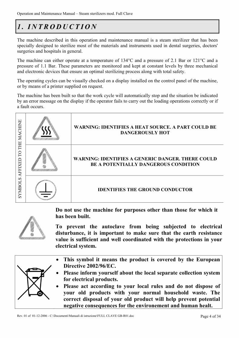
The machine described in this operation and maintenance manual is a steam sterilizer that has been specially designed to sterilize most of the materials and instruments used in dental surgeries, doctors' surgeries and hospitals in general. The machine can either operate at a temperature of 134°C and a pressure of 2.1 Bar or 121°C and a pressure of 1.1 Bar. These parameters are monitored and kept at constant levels by three mechanical and electronic devices that ensure an optimal sterilizing process along with total safety. The operating cycles can be visually checked on a display installed on the control panel of the machine, or by means of a printer supplied on request. The machine has been built so that the work cycle will automatically stop and the situation be indicated by an error message on the display if the operator fails to carry out the loading operations correctly or if a fault occurs.
WARNING: IDENTIFIES A HEAT SOURCE. A PART COULD BE
DANGEROUSLY HOT
WARNING: IDENTIFIES A GENERIC DANGER. THERE COULD
BE A POTENTIALLY DANGEROUS CONDITION
SYM
BO
LS A
FFIX
ED T
O T
HE
MA
CH
INE
IDENTIFIES THE GROUND CONDUCTOR
Do not use the machine for purposes other than those for which it has been built.
To prevent the autoclave from being subjected to electrical disturbance, it is important to make sure that the earth resistance value is sufficient and well coordinated with the protections in your electrical system.
• This symbol it means the product is covered by the European Directive 2002/96/EC.
• Please inform yourself about the local separate collection system for electrical products.
• Please act according to your local rules and do not dispose of your old products with your normal household waste. The correct disposal of your old product will help prevent potential negative consequences for the environement and human healt.
Operation and Maintenance Manual – Steam sterilizers mod. Full Clave
Rev. 01 of 01-12-2006 - C:\Documenti\Manuali di istruzione\FULL CLAVE GB-R01.doc Page 5 of 34
2 . T E C H N I C A L S P E C I F I C A T I O N S
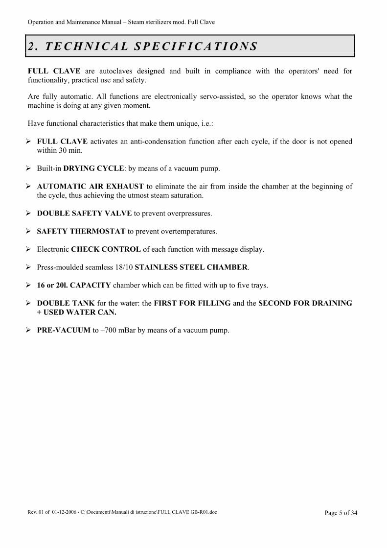
FULL CLAVE are autoclaves designed and built in compliance with the operators' need for functionality, practical use and safety. Are fully automatic. All functions are electronically servo-assisted, so the operator knows what the machine is doing at any given moment. Have functional characteristics that make them unique, i.e.:
FULL CLAVE activates an anti-condensation function after each cycle, if the door is not opened
within 30 min. Built-in DRYING CYCLE: by means of a vacuum pump.
AUTOMATIC AIR EXHAUST to eliminate the air from inside the chamber at the beginning of
the cycle, thus achieving the utmost steam saturation. DOUBLE SAFETY VALVE to prevent overpressures.
SAFETY THERMOSTAT to prevent overtemperatures.
Electronic CHECK CONTROL of each function with message display.
Press-moulded seamless 18/10 STAINLESS STEEL CHAMBER.
16 or 20l. CAPACITY chamber which can be fitted with up to five trays.
DOUBLE TANK for the water: the FIRST FOR FILLING and the SECOND FOR DRAINING
+ USED WATER CAN. PRE-VACUUM to –700 mBar by means of a vacuum pump.

Operation and Maintenance Manual – Steam sterilizers mod. Full Clave
Rev. 01 of 01-12-2006 - C:\Documenti\Manuali di istruzione\FULL CLAVE GB-R01.doc Page 6 of 34
Description Unit of measurement Values Power source voltage rating V 230 V.a.c. ~ Power source frequency Hz 50 Machine power rating W 2300 Boiler volume mm Ø 240 x 340 Ø 240 x 440 (B20)Operating pressure Bar 2.1 - 1.1 Machine dimensions X, Y, Z mm Prof. 590 x Larg. 480 x H 520Gross weight Kg 50 Pack dimensions mm Prof. 680 x Larg. 560 x H 670Operating temperatures °C + 3°C …… + 35°C Distance from walls cm 8 - 10
X = depth Y = width Z = height
The electrical system is protected against the risk of over-currents installed inside the machine by two 15 A delayed action fuses ( T 15 A ). The electronic control and powering boards protect the various users by means of 3 dedicated fuses: 2 quick-acting 1 A types (F 1 A) and one 100 mA delayed action type (T 100 mA) – (see enclosed wiring diagram). Only have these fuses changed by a skilled electrician. The noise level of the machine has been tested. The continuous equivalent weighted acoustic pressure level A is less than 70 dB (A) and the continuous equivalent weighted acoustic power level A does not exceed 85 dB (A). The measured noise level measured is therefore very low. For this reason, the operator need not take any particular measures (also in view of the fact that the machine operates automatically).
DATA AND SPECIFICATIONS OF THE PRESSURIZED VESSEL:
Serial N° of vessel, Serial N° of door Month N°, Year N° (see internal label) Max. operating pressure: 2.2 Bar Max. operating temperature: 160°C Min. operating pressure: -0.9 Bar Test pressure: 8 Bar Reference standards: TRD 421 Volume of vessel: 16 or 20l.
DATA AND SPECIFICATIONS OF THE PRESSURIZED VESSEL:
Serial N° of vessel, Serial N° of door Month N°, Year N° (see internal label) Max. operating pressure: 3 Bar. Max. operating temperature: 160°C Test pressure: 12 Bar. Reference standards: TRD 421 Volume of vessel: 3 lt.
Operation and Maintenance Manual – Steam sterilizers mod. Full Clave
Rev. 01 of 01-12-2006 - C:\Documenti\Manuali di istruzione\FULL CLAVE GB-R01.doc Page 7 of 34
3 . G E N E R A L R E C O M M E N D A T I O N S
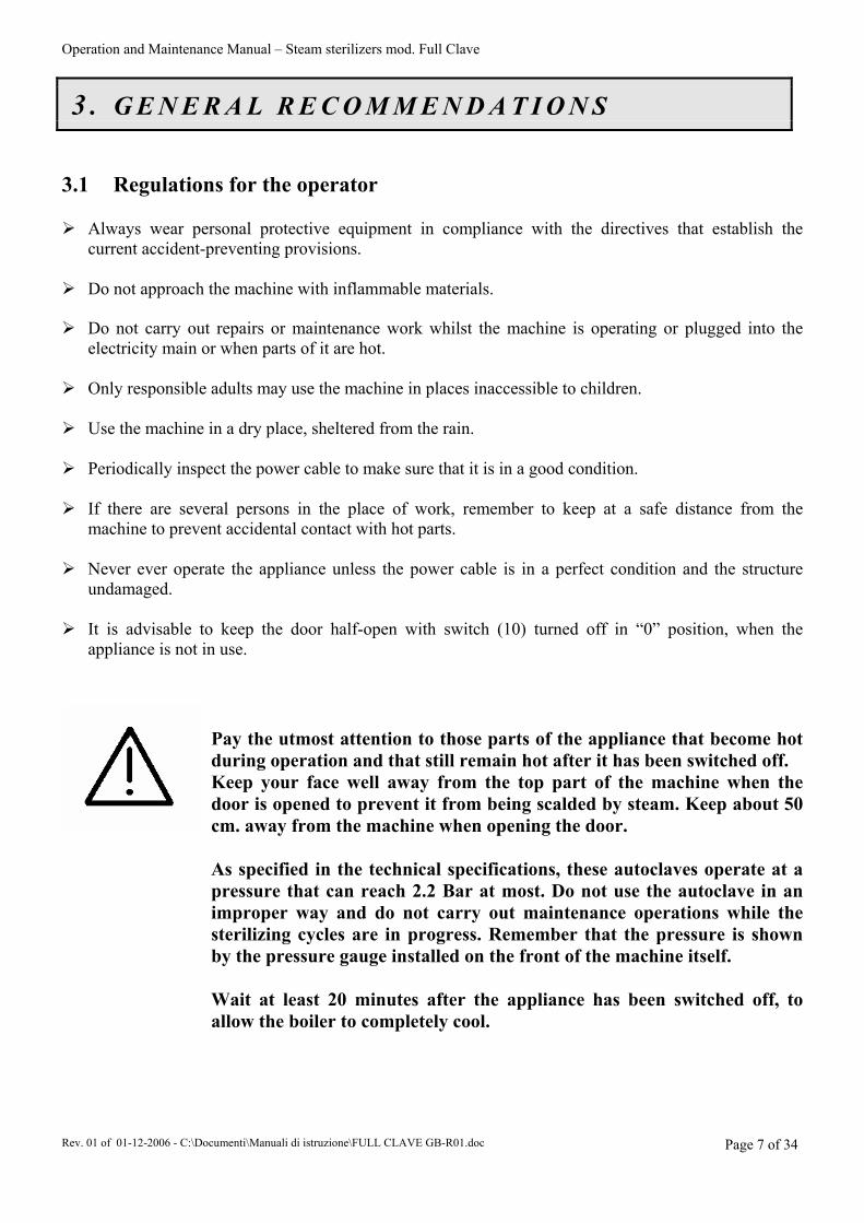
3.1 Regulations for the operator
Always wear personal protective equipment in compliance with the directives that establish the current accident-preventing provisions.
Do not approach the machine with inflammable materials. Do not carry out repairs or maintenance work whilst the machine is operating or plugged into the
electricity main or when parts of it are hot. Only responsible adults may use the machine in places inaccessible to children.
Use the machine in a dry place, sheltered from the rain.
Periodically inspect the power cable to make sure that it is in a good condition.
If there are several persons in the place of work, remember to keep at a safe distance from the
machine to prevent accidental contact with hot parts.
Never ever operate the appliance unless the power cable is in a perfect condition and the structure undamaged.
It is advisable to keep the door half-open with switch (10) turned off in “0” position, when the
appliance is not in use.
Pay the utmost attention to those parts of the appliance that become hot during operation and that still remain hot after it has been switched off. Keep your face well away from the top part of the machine when the door is opened to prevent it from being scalded by steam. Keep about 50 cm. away from the machine when opening the door. As specified in the technical specifications, these autoclaves operate at a pressure that can reach 2.2 Bar at most. Do not use the autoclave in an improper way and do not carry out maintenance operations while the sterilizing cycles are in progress. Remember that the pressure is shown by the pressure gauge installed on the front of the machine itself. Wait at least 20 minutes after the appliance has been switched off, to allow the boiler to completely cool.
Operation and Maintenance Manual – Steam sterilizers mod. Full Clave
Rev. 01 of 01-12-2006 - C:\Documenti\Manuali di istruzione\FULL CLAVE GB-R01.doc Page 8 of 34
4 . L O C A T I O N O F T H E C O N T R O L S
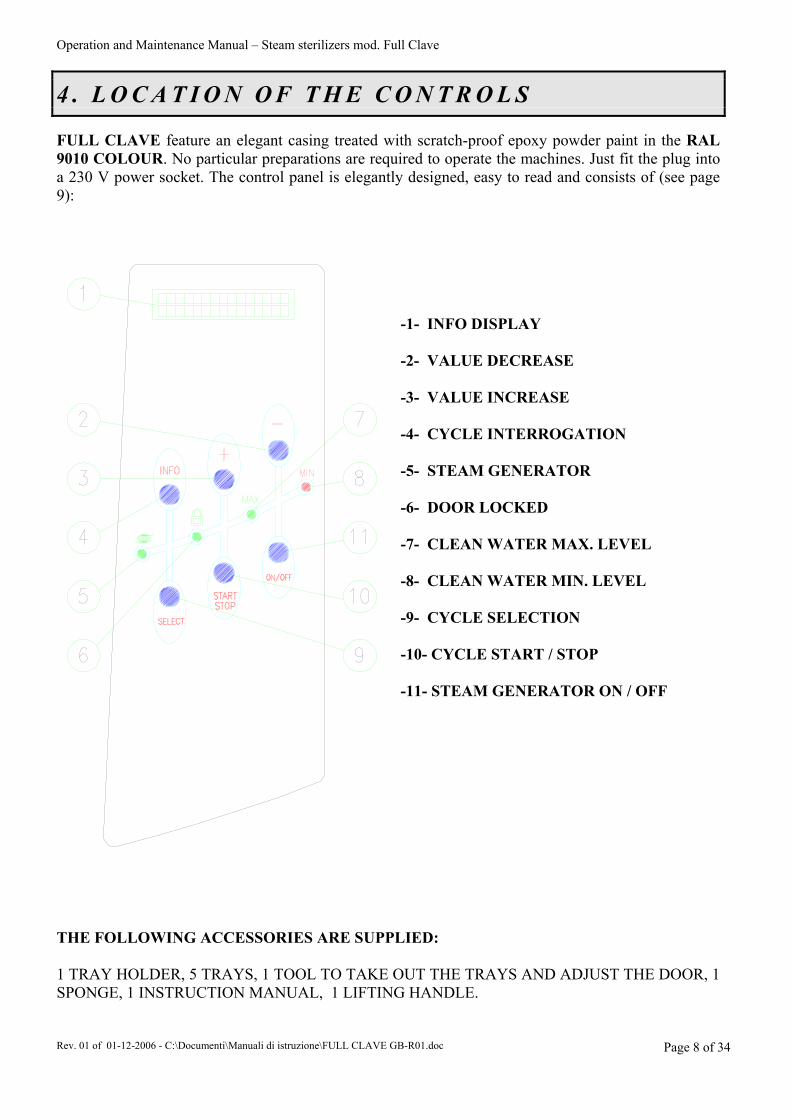
FULL CLAVE feature an elegant casing treated with scratch-proof epoxy powder paint in the RAL 9010 COLOUR. No particular preparations are required to operate the machines. Just fit the plug into a 230 V power socket. The control panel is elegantly designed, easy to read and consists of (see page 9):
-1- INFO DISPLAY -2- VALUE DECREASE -3- VALUE INCREASE -4- CYCLE INTERROGATION -5- STEAM GENERATOR -6- DOOR LOCKED -7- CLEAN WATER MAX. LEVEL -8- CLEAN WATER MIN. LEVEL -9- CYCLE SELECTION -10- CYCLE START / STOP -11- STEAM GENERATOR ON / OFF
THE FOLLOWING ACCESSORIES ARE SUPPLIED: 1 TRAY HOLDER, 5 TRAYS, 1 TOOL TO TAKE OUT THE TRAYS AND ADJUST THE DOOR, 1 SPONGE, 1 INSTRUCTION MANUAL, 1 LIFTING HANDLE.

Operation and Maintenance Manual – Steam sterilizers mod. Full Clave
Rev. 01 of 01-12-2006 - C:\Documenti\Manuali di istruzione\FULL CLAVE GB-R01.doc Page 9 of 34
-12- DOOR OPENING LEVER -13- FILL TANK -14- DRAIN TANK -15- PRINTER -16- BACTERIOLOGICAL FILTER
INFO DISPLAY READING:
A=Two boxes indicating the cycle number B=Five boxes indicating the cycle temperature C=Seven boxes indicating the name of the cycle D=Seven boxes indicating the temperature in the chamber E=Eight boxes indicating the pressure in the chamber
LANGUAGE, DATE AND TIME SETTINGS:
When the door is open and the machine on, press key (4) to display the machine data settings (amongst which the date and time) in succession. Keep buttons (3) and (4) depressed for about 10 seconds at the same time in order to edit these data. The first setting displayed is the language selection. This can be changed by scrolling the various options with buttons (2) and (3). Use button (10) to confirm the required language or pass on to the next setting. (However, the printer will always print in English). The second setting concerns the presence of the external can. This setting must never be changed and must therefore be left with the preset value 0 (zero). The third type of variable settings are the date and time. Use the method described for language variation to edit these data.
To ensure that the machine operates correctly, make sure that the value referring to the presence of the external can is never changed. Once this setting has been accessed, it must be confirmed with key (10) without having been changed. Always maintain 0 (zero) value in this field.
Operation and Maintenance Manual – Steam sterilizers mod. Full Clave
Rev. 01 of 01-12-2006 - C:\Documenti\Manuali di istruzione\FULL CLAVE GB-R01.doc Page 10 of 34
5 . S T A R T I N G A N D S E T T I N G A T W O R K
5.1 Removing the machine from the packing
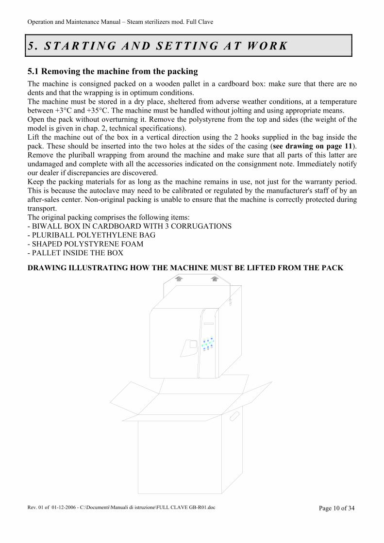
The machine is consigned packed on a wooden pallet in a cardboard box: make sure that there are no dents and that the wrapping is in optimum conditions. The machine must be stored in a dry place, sheltered from adverse weather conditions, at a temperature between +3°C and +35°C. The machine must be handled without jolting and using appropriate means. Open the pack without overturning it. Remove the polystyrene from the top and sides (the weight of the model is given in chap. 2, technical specifications). Lift the machine out of the box in a vertical direction using the 2 hooks supplied in the bag inside the pack. These should be inserted into the two holes at the sides of the casing (see drawing on page 11). Remove the pluriball wrapping from around the machine and make sure that all parts of this latter are undamaged and complete with all the accessories indicated on the consignment note. Immediately notify our dealer if discrepancies are discovered. Keep the packing materials for as long as the machine remains in use, not just for the warranty period. This is because the autoclave may need to be calibrated or regulated by the manufacturer's staff of by an after-sales center. Non-original packing is unable to ensure that the machine is correctly protected during transport. The original packing comprises the following items: - BIWALL BOX IN CARDBOARD WITH 3 CORRUGATIONS - PLURIBALL POLYETHYLENE BAG - SHAPED POLYSTYRENE FOAM - PALLET INSIDE THE BOX DRAWING ILLUSTRATING HOW THE MACHINE MUST BE LIFTED FROM THE PACK
Operation and Maintenance Manual – Steam sterilizers mod. Full Clave
Rev. 01 of 01-12-2006 - C:\Documenti\Manuali di istruzione\FULL CLAVE GB-R01.doc Page 11 of 34
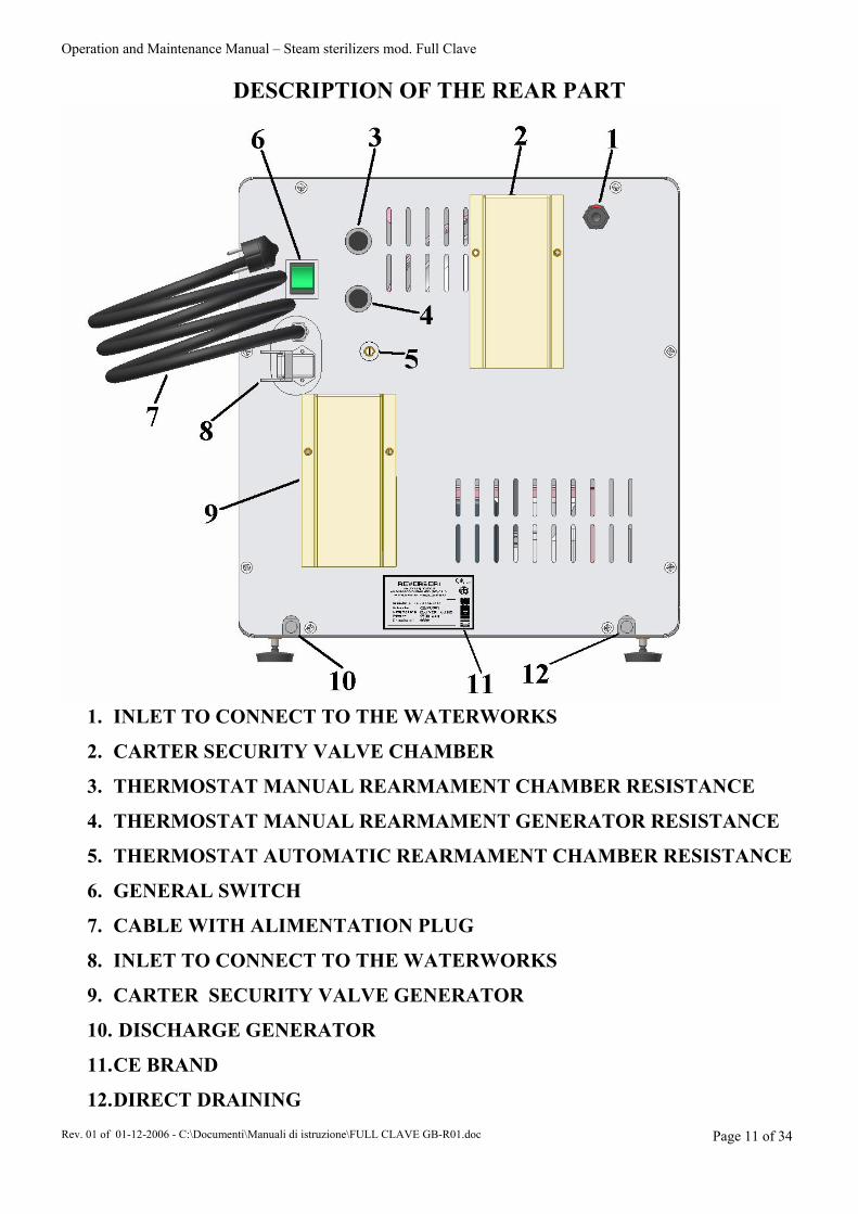
DESCRIPTION OF THE REAR PART
1. INLET TO CONNECT TO THE WATERWORKS
2. CARTER SECURITY VALVE CHAMBER
3. THERMOSTAT MANUAL REARMAMENT CHAMBER RESISTANCE
4. THERMOSTAT MANUAL REARMAMENT GENERATOR RESISTANCE
5. THERMOSTAT AUTOMATIC REARMAMENT CHAMBER RESISTANCE
6. GENERAL SWITCH
7. CABLE WITH ALIMENTATION PLUG
8. INLET TO CONNECT TO THE WATERWORKS
9. CARTER SECURITY VALVE GENERATOR
10. DISCHARGE GENERATOR
11. CE BRAND
12. DIRECT DRAINING

Operation and Maintenance Manual – Steam sterilizers mod. Full Clave
Rev. 01 of 01-12-2006 - C:\Documenti\Manuali di istruzione\FULL CLAVE GB-R01.doc Page 12 of 34
5.2 Installation and preliminary inspections
The installer is obliged to make sure that the place in which the sterilizer is installed is fit for that purpose (CEI 62/4).
Install the autoclave in a well ventilated place, well away from sinks, heat sources, grinders and from all other machines.
Place the autoclave delicately on to a perfectly flat surface. Take care to leave a space of about 8-10 cm all around the machine to allow for aeration and make sure that the internal chamber is perfectly parallel to the ground.
Comply with the following instructions to simply and efficiently check that the machine has been positioned correctly:
Open the door of the machine using the handle (12). Remove the tray holders complete with trays.
Fit the electric plug into a socket WITH A CAPACITY OF AT LEAST 16 Ampere AND EQUIPPED WITH AN EARTH CONNECTION. Make sure that the mains voltage rating corresponds to the value indicated on the label at the rear of the machine (230 Volts).
FULL CLAVE must only be filled with DISTILLED WATER to ensure that the electrical and air-operated devices operate efficiently and are long lasting.
Never connect the plug of the machine to a reduction.
Use a bubble level to make sure that the surface on which the appliance is to be positioned is perfectly horizontal.
Fill out and send off the warranty form.
Operation and Maintenance Manual – Steam sterilizers mod. Full Clave
Rev. 01 of 01-12-2006 - C:\Documenti\Manuali di istruzione\FULL CLAVE GB-R01.doc Page 13 of 34
6 . G E N E R A L I N S T R U C T I O N S F O R U S E
6.1 Directions for use
OPEN THE DOOR BY MEANS OF THE HANDLE (12).
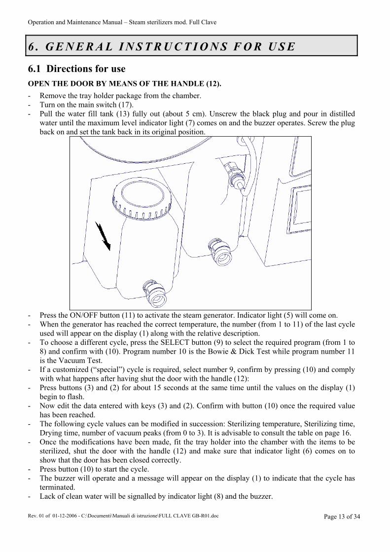
- Remove the tray holder package from the chamber. - Turn on the main switch (17). - Pull the water fill tank (13) fully out (about 5 cm). Unscrew the black plug and pour in distilled
water until the maximum level indicator light (7) comes on and the buzzer operates. Screw the plug back on and set the tank back in its original position.
- Press the ON/OFF button (11) to activate the steam generator. Indicator light (5) will come on. - When the generator has reached the correct temperature, the number (from 1 to 11) of the last cycle
used will appear on the display (1) along with the relative description. - To choose a different cycle, press the SELECT button (9) to select the required program (from 1 to
8) and confirm with (10). Program number 10 is the Bowie & Dick Test while program number 11 is the Vacuum Test.
- If a customized (“special”) cycle is required, select number 9, confirm by pressing (10) and comply with what happens after having shut the door with the handle (12):
- Press buttons (3) and (2) for about 15 seconds at the same time until the values on the display (1) begin to flash.
- Now edit the data entered with keys (3) and (2). Confirm with button (10) once the required value has been reached.
- The following cycle values can be modified in succession: Sterilizing temperature, Sterilizing time, Drying time, number of vacuum peaks (from 0 to 3). It is advisable to consult the table on page 16.
- Once the modifications have been made, fit the tray holder into the chamber with the items to be sterilized, shut the door with the handle (12) and make sure that indicator light (6) comes on to show that the door has been closed correctly.
- Press button (10) to start the cycle. - The buzzer will operate and a message will appear on the display (1) to indicate that the cycle has
terminated. - Lack of clean water will be signalled by indicator light (8) and the buzzer.
Operation and Maintenance Manual – Steam sterilizers mod. Full Clave
Rev. 01 of 01-12-2006 - C:\Documenti\Manuali di istruzione\FULL CLAVE GB-R01.doc Page 14 of 34
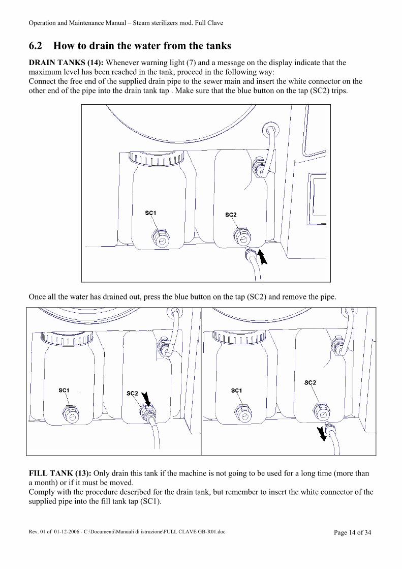
6.2 How to drain the water from the tanks DRAIN TANKS (14): Whenever warning light (7) and a message on the display indicate that the maximum level has been reached in the tank, proceed in the following way: Connect the free end of the supplied drain pipe to the sewer main and insert the white connector on the other end of the pipe into the drain tank tap . Make sure that the blue button on the tap (SC2) trips.
Once all the water has drained out, press the blue button on the tap (SC2) and remove the pipe.
FILL TANK (13): Only drain this tank if the machine is not going to be used for a long time (more than a month) or if it must be moved. Comply with the procedure described for the drain tank, but remember to insert the white connector of the supplied pipe into the fill tank tap (SC1).
Operation and Maintenance Manual – Steam sterilizers mod. Full Clave
Rev. 01 of 01-12-2006 - C:\Documenti\Manuali di istruzione\FULL CLAVE GB-R01.doc Page 15 of 34
6.3 After work
After the operations have terminated, move the green main switch (17) to position 0 and open the door.
Pay particular attention to the temperature of the various components when the machine is switched off. Wait a few minutes to allow them to cool.
7 . H O W T O A R R A N G E T H E I N S T R U M E N T S F O R T H E S T E R I L I Z I N G P R O C E S S
Before being sterilized, the instruments must be cleaned to remove blood residues, incrustations, foreign bodies, etc. These impurities can damage the items being sterilized, the autoclave components and prevent the sterilizing process from being correctly carried out. These instruments must be made of NON-ferrous material since they could damage the other instruments or the autoclave itself. To achieve perfect sterilizing, it is therefore important to proceed in the following way: 1. Rinse and brush the instruments under running water immediately after use to remove all deposits. 2. Place the instruments in the ultrasound machine with distilled water and detergent solution if
possible. 3. Thoroughly rinse the instruments in demineralised water to prevent scaling stains. 4. Dry the instruments to eliminate all water residues which could lead to oxidation. 5. Wash, rinse and dry the supplied trays and make sure that they are perfectly clean. 6. To ensure that packaged instruments are perfectly dried, we recommend use of support art. M9050
supplied as an optional. 7. If loose instruments must be sterilized, it is advisable to cover the trays with a paper or fabric
napkin to prevent direct contact with the tray surface: do not place the instruments straight on to the trays.
8. Scissors and forceps should be slightly opened. Mirrors and containers should be placed upside down for the sterilizing process.
9. It is advisable to keep the instruments separated from each other to achieve a better sterilizing action. Overloading will impair the sterilizing process.
10. If packaged instruments must be sterilized on the trays, place the packets with their transparent side downwards and do not overlap. The packets should not be too large. Drying will be difficult if their edges overlap.
11. The machine can operate with a maximum 3 Kg load. Sterilizing handpieces: Carefully read the handpiece operation manual with particular attention to the part about sterilizing. Wrap the handpiece in the special sterilizing cloth. Place the wrapped handpiece on a NON-perforated tray to prevent spilt lubricating oil from
polluting the pipes of the autoclave. Proceed with a short cycle 121°C sterilizing program. Remember to immediately remove the handpiece from the autoclave at the end of the sterilizing
process. For a valid sterilizing process, it is obligatory to add a chemical indicator for each cycle.
Operation and Maintenance Manual – Steam sterilizers mod. Full Clave
Rev. 01 of 01-12-2006 - C:\Documenti\Manuali di istruzione\FULL CLAVE GB-R01.doc Page 16 of 34
7.1 Sterilizing table
Cycle N°
CYCLES AT 121°
FRACTIONED VACUUM
(N°)
STERILIZING TIME (Min.)
DRYING TIME (Min.)
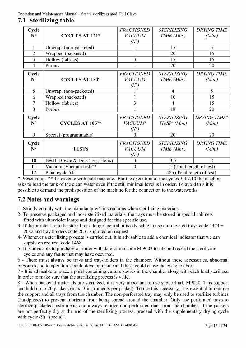
1 Unwrap. (non-packeted) 1 15 5 2 Wrapped (packeted) 1 20 15 3 Hollow (fabrics) 3 15 15 4 Porous 1 20 20
Cycle N°
CYCLES AT 134°
FRACTIONED VACUUM
(N°)
STERILIZING TIME (Min.)
DRYING TIME (Min.)
5 Unwrap. (non-packeted) 1 4 5 6 Wrapped (packeted) 1 10 15 7 Hollow (fabrics) 3 4 15 8 Porous 1 18 20
Cycle N°
CYCLES AT 105°*
FRACTIONED VACUUM*
(N°)
STERILIZING TIME* (Min.)
DRYING TIME*(Min.)
9 Special (programmable) 0 20 20
Cycle N°
TESTS
FRACTIONED VACUUM
(N°)
STERILIZING TIME (Min.)
DRYING TIME (Min.)
10 B&D (Bowie & Dick Test, Helix) 3 3,5 2 11 Vacuum (Vacuum test)** 0 15 (Total length of test) 12 Phial cycle 54° 1 48h (Total length of test)
* Preset value. ** To execute with cold machine. For the execution of the cycles 3,4,7,10 the machine asks to load the tank of the clean water even if the still minimal level is in order. To avoid this it is possible to demand the predisposition of the machine for the connection to the waterworks.
7.2 Notes and warnings
1- Strictly comply with the manufacturer's instructions when sterilizing materials. 2- To preserve packaged and loose sterilized materials, the trays must be stored in special cabinets
fitted with ultraviolet lamps and designed for this specific use. 3- If the articles are to be stored for a longer period, it is advisable to use our covered trays code 1474 +
2682 and tray holders code 2631 supplied on request. 4- Whenever a sterilizing process is carried out, it is advisable to add a chemical indicator that we can
supply on request, code 1468. 5- It is advisable to purchase a printer with date stamp code M 9003 to file and record the sterilizing
cycles and any faults that may have occurred. 6 - There must always be trays and tray-holders in the chamber. Without these accessories, abnormal pressures and temperatures could develop inside and these could cause the cycle to abort. 7 - It is advisable to place a phial containing culture spores in the chamber along with each load sterilized in order to make sure that the sterilizing process is valid. 8 - When packeted materials are sterilized, it is very important to use support art. M9050. This support can hold up to 20 packets (max. 3 instruments per packet). To use this accessory, it is essential to remove the support and all trays from the chamber. The non-perforated tray may only be used to sterilize turbines (handpieces) to prevent lubricant from being spread around the chamber. Only use perforated trays to sterilize packeted instruments and always remove non-perforated ones from the chamber. If the packets are not perfectly dry at the end of the sterilizing process, proceed with the supplementary drying cycle with cycle (9) “special”.
Operation and Maintenance Manual – Steam sterilizers mod. Full Clave
Rev. 01 of 01-12-2006 - C:\Documenti\Manuali di istruzione\FULL CLAVE GB-R01.doc Page 17 of 34
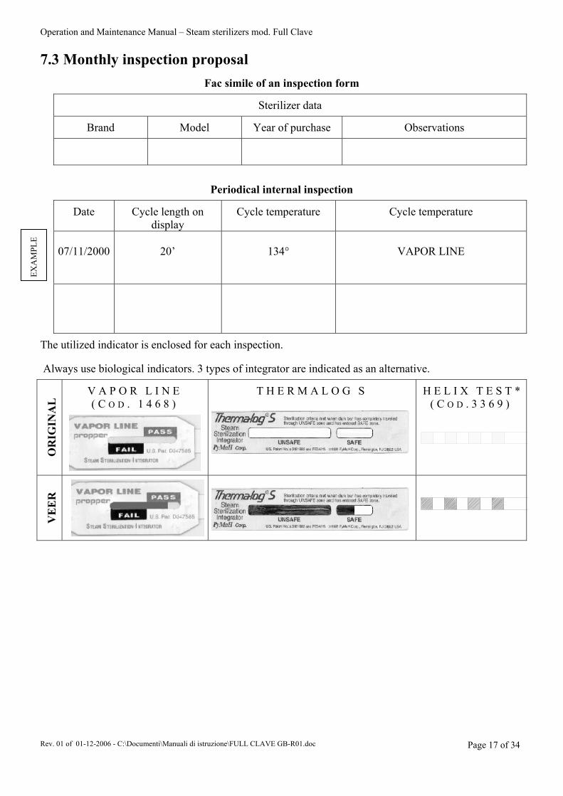
7.3 Monthly inspection proposal
Fac simile of an inspection form
Sterilizer data
Brand
Model
Year of purchase
Observations
Periodical internal inspection
Date
Cycle length on display
Cycle temperature
Cycle temperature
07/11/2000
20’
134°
VAPOR LINE
The utilized indicator is enclosed for each inspection. Always use biological indicators. 3 types of integrator are indicated as an alternative.
OR
IGIN
AL
.
V A P O R L I N E ( C O D . 1 4 6 8 )
T H E R M A L O G S
H E L I X T E S T *( C O D . 3 3 6 9 )
VE
ER
EXA
MPL
E
Operation and Maintenance Manual – Steam sterilizers mod. Full Clave
Rev. 01 of 01-12-2006 - C:\Documenti\Manuali di istruzione\FULL CLAVE GB-R01.doc Page 18 of 34
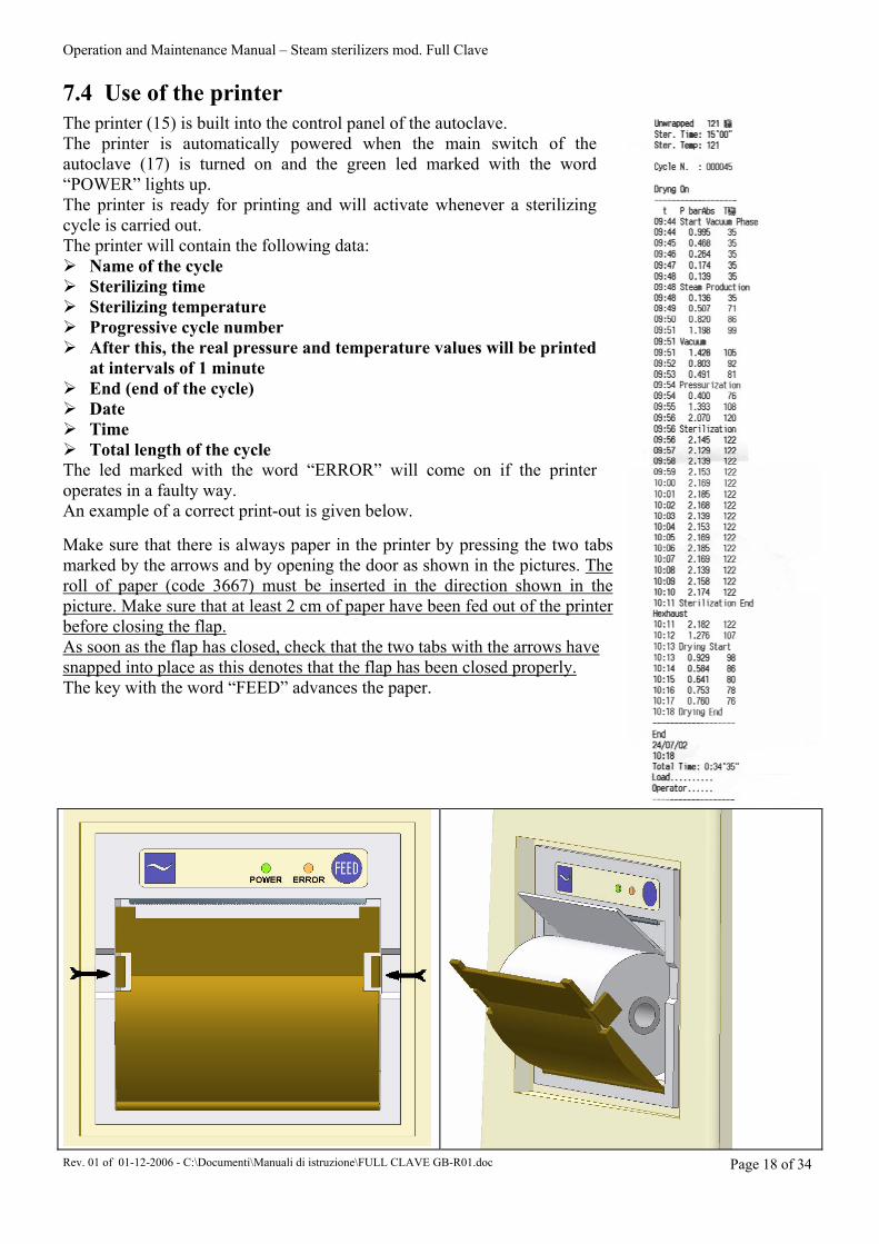
7.4 Use of the printer
The printer (15) is built into the control panel of the autoclave. The printer is automatically powered when the main switch of the autoclave (17) is turned on and the green led marked with the word “POWER” lights up. The printer is ready for printing and will activate whenever a sterilizing cycle is carried out. The printer will contain the following data: Name of the cycle Sterilizing time Sterilizing temperature Progressive cycle number After this, the real pressure and temperature values will be printed
at intervals of 1 minute End (end of the cycle) Date Time Total length of the cycle
The led marked with the word “ERROR” will come on if the printer operates in a faulty way. An example of a correct print-out is given below. Make sure that there is always paper in the printer by pressing the two tabs marked by the arrows and by opening the door as shown in the pictures. The roll of paper (code 3667) must be inserted in the direction shown in the picture. Make sure that at least 2 cm of paper have been fed out of the printer before closing the flap. As soon as the flap has closed, check that the two tabs with the arrows have snapped into place as this denotes that the flap has been closed properly. The key with the word “FEED” advances the paper.

Operation and Maintenance Manual – Steam sterilizers mod. Full Clave
Rev. 01 of 01-12-2006 - C:\Documenti\Manuali di istruzione\FULL CLAVE GB-R01.doc Page 19 of 34
8. MESSAGES DISPLAYED
8.1 Alarm management
In the ON and CYCLE statuses, the system supervises the functional events that cause an alarm status if faults occur. In the alarm status, the system issues a rhythmic sound that can be interrupted by resetting the alarm itself.
RESET: This is done by pressing the “START/STOP” key (10). If a fatal error has occurred, the autoclave will remain in the OFF status. CODE 00 TRIAC ALARM (FATAL) Autotest handled by the microprocessor of the
heating system. CODE 01 OVERTEMPERATURE ALARM (FATAL) The temperature exceeds 150°. CODE 02 HEATING ALARM (FATAL) The gradient of the autoclave is less than the
established value during the heating phase with indicator light (5) on.
CODE 03 INSUFFICIENT STEAM (FATAL) The parameter between temperature and pressure is different from the preset value.
CODE 04 WATER LEVEL TOO LOW The level of the water in the fill tank (13) is less than the minimum mark. Indicator light (8) on.
CODE 06 MAXIMUM LEVEL IN DRAIN TANK The level of the water in the drain tank (14) is at the maximum mark. Indicator light (7) on.
CODE 07 DOOR OPEN (FATAL) The door has not been shut properly. Cod.08 TIME OUT LEVEL STEAM
GENERATOR (FATALE) Level staem generator not maximum down time standard.
Cod.09 STOP MANUAL (FATALE) Cycle stopped from the operator. CODE 10 INSUFFICIENT VACUUM (FATAL) The preset vacuum value has not been reached in the
chamber within the preset time. CODE 11 INSUFFICIENT FRACTIONED VACUUM
(FATAL) The preset vacuum peak is not reached in the chamber within the preset time.
CODE 13 LEVEL PROBE ALARM (FATAL) One or more of the tank probes is/are defective. CODE 14 PRESSURIZING ALARM (FATAL) The steam generator has failed to reach the preset
temperature gradient. CODE 15 STERILISATION BAND EXCEEDED
(FATAL) The sterilisation temperature band has been exceeded.
CODE 16 STERILISATION BAND NOT REACHED (FATAL)
The sterilisation temperature band has not been reached
CODE 17 POWER DROP (FATAL) Power supply has been cut off. CODE 18 TIME OUT BOILER (FATAL) The preset temperature value has not been reached
in the steam generator within the preset time.
NOTE: If the operator resets before the error message has been printed, the alarm will not appear on the printout. Non-fatal alarms that occur at the beginning of the cycle are not printed as the cycle is actually not started. OTHER MESSAGES THAT APPEAR ON THE DISPLAY:
WAIT FOR STEAM GENERATOR TO HEAT: This is displayed when the machine is powered and still cold (wait a few minutes before proceeding with the sterilizing cycle).
RELIEVE: This is displayed once the sterilizing time has terminated (the machine is relieving the pressure from the chamber).
END OF CYCLE: This is displayed once pressure relieving and the drying time (if applicable) have terminated (the machine can be opened and the instruments removed).

Operation and Maintenance Manual – Steam sterilizers mod. Full Clave
Rev. 01 of 01-12-2006 - C:\Documenti\Manuali di istruzione\FULL CLAVE GB-R01.doc Page 20 of 34
8.2 Troubleshooting: Solutions/Remedies
Message displayed Causes Remedies Pressure leaks from the door.
Check the door seal. Replace it if it is damaged or caked, then adjust the door pressure (see page 21).
Defective N.O. solenoid valve.
Clean or replace the solenoid valves.
Defective 3-way N.C. solenoid valve.
Worn vacuum pump seals.
Replace the pump seals.
Vacuum pump blocked.
Check operation and/or replace the pump.
INSUFFICIENT VACUUM, INSUFFICIENT FRACTIONED VACUUM
Burnt-out fuse on power board.
Replace fuse on power board.
Air in the chamber. Add a vacuum peak if cycle number 9 (“special”) has been chosen.
The temperature probe hits against an object in the chamber.
Make sure that the temperature probe does not strike against objects in the chamber.
Sterilizing load with too many fabrics.
Reduce the load of fabrics.
OVERTEMPERATURE ALARM,
HEATING ALARM,
Defective transducer.
Open the door and check whether the atmospheric pressure appears on the display (~ 1 bar). Replace the transducer if the value is very different.
Water fill tank empty. Fill the fill tank. WATER LEVEL TOO LOW
Level probe defective or dirty. Clean the fill tank, check and clean the tank level probes (for the technician only).
USED WATER TANK FULL Used water tank full. Empty and rinse the used water tanks. Steam outlet N.C. solenoid valve defective.
Replace the N.C. solenoid valve.
Generator heating elements defective.
Check the heating elements and replace them if necessary.
The safety thermostat has activated.
Reset the thermostat in manual mode and identify the cause of the overtemperature.
PRESSURIZING ALARM
Pressure switch with incorrect setting or defective.
Correctly set (at 3 bar) or replace the pressure switch.
Water feed pump defective.
Check the fill pump and replace it if necessary.
Water inlet filter clogged. Replace the inlet filter.
INSUFFICIENT STEAM
Water level probe defective. Check with a tester and replace if necessary.

Operation and Maintenance Manual – Steam sterilizers mod. Full Clave
Rev. 01 of 01-12-2006 - C:\Documenti\Manuali di istruzione\FULL CLAVE GB-R01.doc Page 21 of 34
The door has been opened during the vacuum phase.
Press the START / STOP button before opening the door.
DOOR OPEN Door micro defective. Check, calibrate or replace the door micro.
Power failure in the electricity main of the building.
Check to find out whether there are faults in the electricity main.
The power socket fails to comply with the standards.
The plug on the machine’s flex must be plugged into a single socket that complies with the standards, without reductions or extensions.
NO POWER
Fuse in the machine burnt-out.
Replace the fuse and find out why it burnt out.
9. FAULTS WITHOUT MESSAGES
Faults Causes Remedies The transparent side of the packets has been turned upwards.
The packets must be placed in the chamber with their transparent sides pointing downwards.
Too many packets overlapping each other.
Only as many as two packets can be placed on top of each other. Use sealer mod. LUX SEAL code M9025/3.
Trays with less than 400 holes have been used.
Use trays with at least 400 holes or the gauze type.
Chamber safety thermostat activated.
Reset the thermostat in manual mode and find out what caused the overtemperature.
Bacteriological filter clogged. Periodically replace the bacteriological filter.
Autoclave positioned on an unlevel surface.
Use a level when positioning the autoclave.
The drain pipe connected to the used water tank is clogged or throttled.
Check the pipe and its connection and replace them if necessary.
TOO MUCH HUMIDITY IN THE PACKETS AFTER STERILIZING
Bacteriological filter solenoid valve defective.
Replace the N.C. solenoid valve of the bacteriological filter.
Door seal defective or damaged.
Clean and, if necessary, replace the door seal, clean the seal housing, adjust the door and its pressure.
WATER UNDER THE MACHINE Fill and drain tank
connections defective. Check the connections of the fill and drain tanks.
Too much pressure in the steam generator.
Calibrate or replace the pressure switch (for the technician only).
STEAM ESCAPES FROM THE SAFETY VALVE
Safety valve defective. Replace the safety valve and notify the manufacturer of the serial number of the valve.
Operation and Maintenance Manual – Steam sterilizers mod. Full Clave
Rev. 01 of 01-12-2006 - C:\Documenti\Manuali di istruzione\FULL CLAVE GB-R01.doc Page 22 of 34
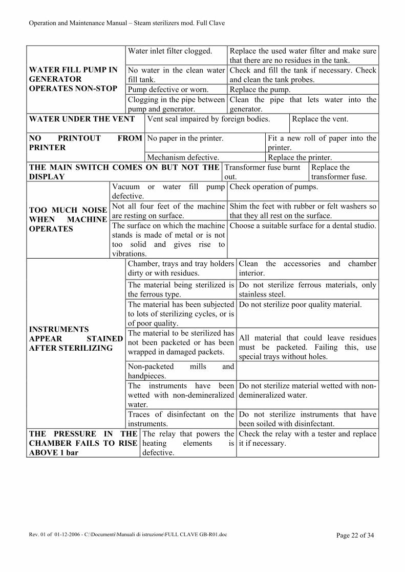
Water inlet filter clogged. Replace the used water filter and make sure that there are no residues in the tank.
No water in the clean water fill tank.
Check and fill the tank if necessary. Check and clean the tank probes.
Pump defective or worn. Replace the pump.
WATER FILL PUMP IN GENERATOR OPERATES NON-STOP
Clogging in the pipe between pump and generator.
Clean the pipe that lets water into the generator.
WATER UNDER THE VENT Vent seal impaired by foreign bodies.
Replace the vent.
No paper in the printer. Fit a new roll of paper into the printer.
NO PRINTOUT FROM PRINTER
Mechanism defective. Replace the printer. THE MAIN SWITCH COMES ON BUT NOT THE DISPLAY
Transformer fuse burnt out.
Replace the transformer fuse.
Vacuum or water fill pump defective.
Check operation of pumps.
Not all four feet of the machine are resting on surface.
Shim the feet with rubber or felt washers so that they all rest on the surface.
TOO MUCH NOISE WHEN MACHINE OPERATES The surface on which the machine
stands is made of metal or is not too solid and gives rise to vibrations.
Choose a suitable surface for a dental studio.
Chamber, trays and tray holders dirty or with residues.
Clean the accessories and chamber interior.
The material being sterilized is the ferrous type.
Do not sterilize ferrous materials, only stainless steel.
The material has been subjected to lots of sterilizing cycles, or is of poor quality.
Do not sterilize poor quality material.
The material to be sterilized has not been packeted or has been wrapped in damaged packets.
All material that could leave residues must be packeted. Failing this, use special trays without holes.
Non-packeted mills and handpieces.
The instruments have been wetted with non-demineralized water.
Do not sterilize material wetted with non-demineralized water.
INSTRUMENTS APPEAR STAINED AFTER STERILIZING
Traces of disinfectant on the instruments.
Do not sterilize instruments that have been soiled with disinfectant.
THE PRESSURE IN THE CHAMBER FAILS TO RISE ABOVE 1 bar
The relay that powers the heating elements is defective.
Check the relay with a tester and replace it if necessary.
Operation and Maintenance Manual – Steam sterilizers mod. Full Clave
Rev. 01 of 01-12-2006 - C:\Documenti\Manuali di istruzione\FULL CLAVE GB-R01.doc Page 23 of 34
1 0 . M A I N T E N A N C E
Carry out maintenance work when the machine is off, with the plug removed from the power socket and when the various components have cooled down. The validity of the declaration of conformity to the laws in force will become void unless the maintenance operations described below are carried out.
10.1 General maintenance The machine needs to be serviced in a particular way. Users are therefore advised to comply with the below listed recommendations:
Periodically check the condition of the electrical system with particular attention to the connection cable. Contact our Technical Assistance Service or specialized personnel if faults are discovered.
Periodically clean the door, the seal and take particular care when cleaning the internal part of the boiler, removing any scaling with the damp sponge (supplied with the machine). Correct cleaning of these parts of the machine will ensure that the sterilizing cycle takes place in the right way.
If the machine is not to be used for a long period of time, leave the door ajar and store it at a room temperature of >8°C.
Use a damp cloth to clean the casing of the machine. Never ever use inflammable liquids for any reason whatsoever.
The bacteriological filter must be changed at least once a year. New ones can be ordered with code 1067.
10.2 Daily routine maintenance
Clear the door seal, door window and generally clean the outer and inner surfaces of the machine. Clean the black silicone door seal, the outer and inner edges and the part where the door rests on the sterilizing chamber and on which the seal must tightly fit. Use the supplied sponge to do this. The soft part of the sponge can be used to clean the seal while the rough part can be used to clean the edge of the chamber. This cleaning operation must be carried out regularly to remove all impurities that could lead to loss of pressure inside the sterilizing chamber. Check the used water level and drain off (14) the actual water into the sewer if necessary. Then wash out the can under running water.
10.3 Weekly routine maintenance
Cleaning the sterilizing chamber (cleaning the trays and tray holders. As specified in section 10.1 “ General maintenance “, all traces of deposits must be removed from the bottom of the chamber. Use the rough side of the supplied sponge for this operation, attempting to eliminate any scaling that may have formed. Rinse everything with the same water used for the sterilizing process. The trays and tray-holders must also be cleaned in this way.
Operation and Maintenance Manual – Steam sterilizers mod. Full Clave
Rev. 01 of 01-12-2006 - C:\Documenti\Manuali di istruzione\FULL CLAVE GB-R01.doc Page 24 of 34
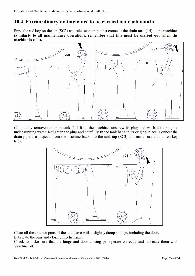
10.4 Extraordinary maintenance to be carried out each month
Press the red key on the tap (SC3) and release the pipe that connects the drain tank (14) to the machine. (Similarly to all maintenance operations, remember that this must be carried out when the machine is cold).
Completely remove the drain tank (14) from the machine, unscrew its plug and wash it thoroughly under running water. Retighten the plug and carefully fit the tank back in its original place. Connect the drain pipe that projects from the machine back into the tank tap (SC3) and make sure that its red key trips.
Clean all the exterior parts of the autoclave with a slightly damp sponge, including the door. Lubricate the pins and closing mechanisms. Check to make sure that the hinge and door closing pin operate correctly and lubricate them with Vaseline oil.

Operation and Maintenance Manual – Steam sterilizers mod. Full Clave
Rev. 01 of 01-12-2006 - C:\Documenti\Manuali di istruzione\FULL CLAVE GB-R01.doc Page 25 of 34
Check the door adjustment: if it is very slow, it must be regulated by turning the regulator at the rear of the door in direction A (see figure) with the supplied wrench. This increases the pressure exercised by the seal. Attempt to shut the door and if it is difficult to close, turn the regulator in direction B (see figure) with the wrench.
10.5 Periodic extraordinary maintenance
To allow the autoclave to operate in a regular way, the manufacturer advises users to carry out a functional test to ensure that the temperature and pressure parameters of the machine comply with the standards required for a correct sterilizing process. These tests must be conducted by personnel authorized by the manufacturer, using calibrated and periodically certified instruments. The autoclave can also be sent to the manufacturer for this test, after form 32/A has been filled out and accepted. The autoclave is able to accept probes for the sterilizing tests. It is advisable to have the appliance subjected to a Total Overhaul by After-sales Service staff at least once every 12 months. The operation of the safety valve installed at the rear of the machine must also be checked at least once every 12 months. This is done by removing the protective casing and re-tightening the ring nut of the valve by hand. To prevent accidents, this operation should obviously be carried out when the machine is cold and off.
Operation and Maintenance Manual – Steam sterilizers mod. Full Clave
Rev. 01 of 01-12-2006 - C:\Documenti\Manuali di istruzione\FULL CLAVE GB-R01.doc Page 26 of 34
10.6 Recommended inspections and replacements (after about 1000 cycles)
1) Make sure that the safety valve functions correctly. - Remove the protective casing - Carry out the 134° cycle and when the maximum pressure has been reached (2.2 bar), unscrew and retighten the knurled ring nut on the safety valve. - Check to make sure that steam issues by unscrewing the ring nut and, vice versa, that total retention is achieved by tightening the same knurled ring nut again. 2) Replace the bacteriological filter 3) Clean and inspect the sterilizing chamber (there must be no trace of scaling or coloured tarnishing) 4) Make sure that the cock (14) is not clogged by blowing through it with a little compressed air. 5) Check the condition of the door seal (change it if it is cut or torn). 6) Make sure that the micro and micro-pressing system allows the door to close correctly. Lubricate with a silicone spray. 7) Replace the filter on the water fill line. Intervention date…………………………signature of the authorized technician……………………… N.B. to send back as photocopy if the building factory required it. 10.7 Corrective actions to prevent faults 1) Change the water inlet filter (internal) code 1484. 2) Clean the "Y" shaped filter (if installed) code 3136, and replace its seal, code 3188. 3) Clean the water filling tank probes, code 0262. 4) Replace the diaphragm and head seal of the vacuum pump (specify the model or serial number of the machine). 5) Replace the N.O. solenoid valve or coil, code 1015. 6) Before closing up the machine, generally inspect the internal components to make sure that they are in a good condition. 7) After these operations have been carried out, print out the report on the first cycles to make sure that the sterilizer operates in a normally efficient way.

Operation and Maintenance Manual – Steam sterilizers mod. Full Clave
Rev. 01 of 01-12-2006 - C:\Documenti\Manuali di istruzione\FULL CLAVE GB-R01.doc Page 27 of 34
ELECTRICAL SYSTEM:

Operation and Maintenance Manual – Steam sterilizers mod. Full Clave
Rev. 01 of 01-12-2006 - C:\Documenti\Manuali di istruzione\FULL CLAVE GB-R01.doc Page 28 of 34
Operation and Maintenance Manual – Steam sterilizers mod. Full Clave
Rev. 01 of 01-12-2006 - C:\Documenti\Manuali di istruzione\FULL CLAVE GB-R01.doc Page 29 of 34
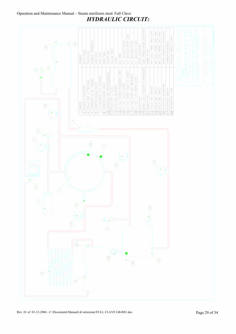
HYDRAULIC CIRCUIT:
Operation and Maintenance Manual – Steam sterilizers mod. Full Clave
Rev. 01 of 01-12-2006 - C:\Documenti\Manuali di istruzione\FULL CLAVE GB-R01.doc Page 30 of 34
Via Don Luigi Sturzo n°6 42021 BARCO ( Reggio Emilia ) ITALY
Tel. 0039 ( 0 )522 / 875159 Fax 0039 ( 0 )522 / 875579
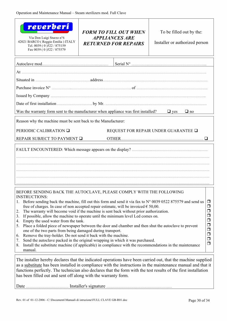
FORM TO FILL OUT WHEN APPLIANCES ARE
RETURNED FOR REPAIRS
To be filled out by the:
Installer or authorized person
Autoclave mod…………………………………………………..….…
Serial N° ……………..………………………………………………....
At …………………………….………………………………………………………………………………………………………………………………….
Situated in ………………………………………………address………………………………………………………………………………………….
Purchase invoice N° ………………..………………………………………………….. of …………….….…….……………………………………..
Issued by Company ……………………………………………………………………………………………………………………………………...
Date of first installation …………………………….. by Mr. …………………………………………………………………………………….…
Was the warranty form sent to the manufacturer when appliance was first installed? yes no
Reason why the machine must be sent back to the Manufacturer: PERIODIC CALIBRATION
REQUEST FOR REPAIR UNDER GUARANTEE
REPAIR SUBJECT TO PAYMENT
OTHER………………………………………………………………………
FAULT ENCOUNTERED: Which message appears on the display? ………………..………………………………………………. ………………………………………………………………………………………………………………………………………………………………………. ………………………………………………………………………………………………………………………………………………………………………. ………………………………………………………………………………………………………………………………………………………………………. ………………………………………………………………………………………………………………………………………………………………………. ……………………………………………………………………………………………………………………………………………………………………….
BEFORE SENDING BACK THE AUTOCLAVE, PLEASE COMPLY WITH THE FOLLOWING INSTRUCTIONS: 1. Before sending back the machine, fill out this form and send it via fax to N° 0039 0522 875579 and send us
free of charges. In case of non accepted repair estimate, will be invoiced € 50,00. 2. The warranty will become void if the machine is sent back without prior authorization. 3. If possible, allow the machine to operate until the minimum level Led comes on. 4. Empty the used water from the tank. 5. Place a folded piece of newspaper between the door and chamber and then shut the autoclave to prevent
one of the two parts from being damaged during transport. 6. Remove the tray-holder. Do not send it back with the machine. 7. Send the autoclave packed in the original wrapping in which it was purchased. 8. Install the substitute machine (if applicable) in compliance with the recommendations in the maintenance
manual.
The installer hereby declares that the indicated operations have been carried out, that the machine supplied as a substitute has been installed in compliance with the instructions in the maintenance manual and that it functions perfectly. The technician also declares that the form with the test results of the first installation has been filled out and sent off along with the warranty form. Date …………………………………… Installer's signature ….………………………………………………….…
Operation and Maintenance Manual – Steam sterilizers mod. Full Clave
Rev. 01 of 01-12-2006 - C:\Documenti\Manuali di istruzione\FULL CLAVE GB-R01.doc Page 31 of 34
It is obligatory for the installer to fill out all parts of this form and to declare that he has complied with all the conditions ensuring that the appliance is correctly installed in compliance with sect. 5.2 of the instruction manual. The installer also declares that he has duly trained the user to operate the machine, with the help of the instruction manual. The technician declares that he has attached the printer ticket to this form along with the warranty form, duly filled out in all parts. The above mentioned documents must be immediately forwarded to the manufacturer. Notes and/or considerations .....................................................................................................…………………………………….………............... ............................................................................................................................................................................................................................................................... ............................................................................................................................................................................................................................................................... ………………………………………………………........................................................................................................................................................................... Installer's signature and date
........................................................................................................
Operation and Maintenance Manual – Steam sterilizers mod. Full Clave
Rev. 01 of 01-12-2006 - C:\Documenti\Manuali di istruzione\FULL CLAVE GB-R01.doc Page 32 of 34
WARRANTY CERTIFICATE This document certifies that the appliance has been correctly manufactured. The appliance will be repaired if it operates in a faulty way during the warranty period owing to manufacturing defects, the manufacturer's judgement over such matters being final. The sterilizing chamber is covered by guarantee for a period of 60 (sixty) months from the date of purchase. This date shall be testified by the enclosed coupon, which must be filled out, duly stamped and signed by the technician who took part in the installation course. The sales invoice or consignment note shall bear witness in the event of disputes. The electrical, electronic parts and nuts and bolts are guaranteed for a period of 24 months. The warranty covers the sole replacement or repair of those parts recognized as possessing manufacturing defects, travel and call costs excluded. Replaced parts shall be returned free port. The ordering party shall be charged for any part that is not returned. All appliances returned for repairs shall only be sent to us free port after authorization and shall be adequately packed, with the sender's name, address and claimed defect clearly indicated. The appliance remains the property of the seller until is has been fully paid for by the purchaser.
THE WARRANTY SHALL BECOME VOID:
1. If the appliance has been repaired, modified or tampered with by the purchaser or by unauthorized third parties.
2. If the purchaser fails to contact the seller or authorized technical center. 3. 18 months from the date of our consignment note. 4. If the customer delays or suspends payments. 5. If the appliance has been damaged by exposure to fire, spilt liquids, natural disasters, has been
dropped or damaged by causes that are not ascribable to manufacturing defects. 6. When the warranty form has not been duly filled out, signed and returned to the manufacturer within
the established time. 7. If the customer uses the appliance improperly, fails to carry out the routine maintenance operations or
services the appliance in a neglectful way.
Operation and Maintenance Manual – Steam sterilizers mod. Full Clave
Rev. 01 of 01-12-2006 - C:\Documenti\Manuali di istruzione\FULL CLAVE GB-R01.doc Page 33 of 34
WARRANTY CERTIFICATE
APPLIANCE:
The undersigned reseller certifies that the warranty has been examined and certifies that the appliance has been consigned and installed in compliance with the instructions given
by the manufacturer on:……………………………………………………………………………………………..
By Mr. …………………………………………………………………………………….…………………………
Address ……………………………………………………………………….……………………………………..
ZIP Code ………………………………………. City ………………………………….………………………….. 1 – FOR THE PURCHASER
…………………………………………………..
TECHNICAL INSTALLER SIGNATURE AND STAMP*
Via Don Luigi Sturzo, 6
42021 BARCO ( Reggio Emilia ) ITALY …………………………………………………… …………………………………………………………… ………………..……………….....
THIS PART OF THE CERTIFICATE MUST BE SENT BACK BY REGISTERED LETTER WITHIN 8 DAYS FROM THE DATE OF PURCHASE
WARRANTY CERTIFICATE
TO BE RETURNED SIGNED AND STAMPED
APPLIANCE:
ATTACCARE QUI L’ETICHETTA
The undersigned reseller certifies that the warranty has been examined and certifies that the appliance has been consigned and installed in compliance with the instructions given
by the manufacturer on:……………………………………………………………………………………………..
By Mr. …………………………………………………………………………………….…………………………
Address ……………………………………………………………………….……………………………………..
ZIP Code …………………………… City ……………………………. Buyer signature……………………………………. 2 –FOR THE MANUFACTURER
………………………………………………….. RESELLER'S SIGNATURE AND STAMP
Via Don Luigi Sturzo, 6
42021 BARCO ( Reggio Emilia ) ITALY
* The technical installer must be authorized by the building factory.
Operation and Maintenance Manual – Steam sterilizers mod. Full Clave
Rev. 01 of 01-12-2006 - C:\Documenti\Manuali di istruzione\FULL CLAVE GB-R01.doc Page 34 of 34
MEDICAL DIVISION
Via Don Luigi Sturzo nº 6
42021 BARCO (Reggio Emilia) Tel. +39 – 0522 - 875159 / 875195 Fax +39 – 0522 - 875736 / 875579
ITALIA
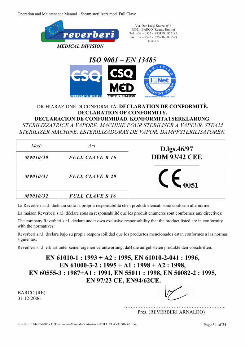
ISO 9001 – EN 13485
DICHIARAZIONE DI CONFORMITÀ. DECLARATION DE CONFORMITÈ. DECLARATION OF CONFORMITY.
DECLARACION DE CONFORMIDAD. KONFORMITATSERKLARUNG. STERILIZZATRICE A VAPORE. MACHINE POUR STERILISER A VAPEUR. STEAM
STERILIZER MACHINE. ESTERILIZADORAS DE VAPOR. DAMPFSTERILISATOREN.
Mod:
Art.
M9010/30
FULL CLAVE B 16
M9010/31
FULL CLAVE B 20
M9010/32
FULL CLAVE S 16
D.lgs.46/97
DDM 93/42 CEE
La Reverberi s.r.l. dichiara sotto la propria responsabilità che i prodotti elencati sono conformi alle norme:
La maison Reverberi s.r.l. déclare sous sa responsabilité que les produit enumeres sont conformes aux directives:
The company Reverberi s.r.l. declare under own exclusive responsability that the product listed are in conformity with the normatives:
Reverberi s.r.l. declara bajo su propia responsabilidad que los productos mencionados estan conformes a las normas siguientes:
Reverberi s.r.l. erklart unter seiner cigenen verantwortung, daB die aufgelisteten produkte den vorschriften:
EN 61010-1 : 1993 + A2 : 1995, EN 61010-2-041 : 1996, EN 61000-3-2 : 1995 + A1 : 1998 + A2 : 1998,
EN 60555-3 : 1987+A1 : 1991, EN 55011 : 1998, EN 50082-2 : 1995, EN 97/23 CE, EN94/62CE.
BARCO (RE) 01-12-2006
…………………………………………………….. Pres. (REVERBERI ARNALDO)