full bore jip™ ball valves (pn 16/25/40)125 219.1 4 139.7 125 355 378 154 205 146 60 250 129 58...
TRANSCRIPT
© Danfoss | 2019.04 VD.HB.U9.02 | 1
Full bore JIP™ ball valves (PN 16/25/40)Data sheet
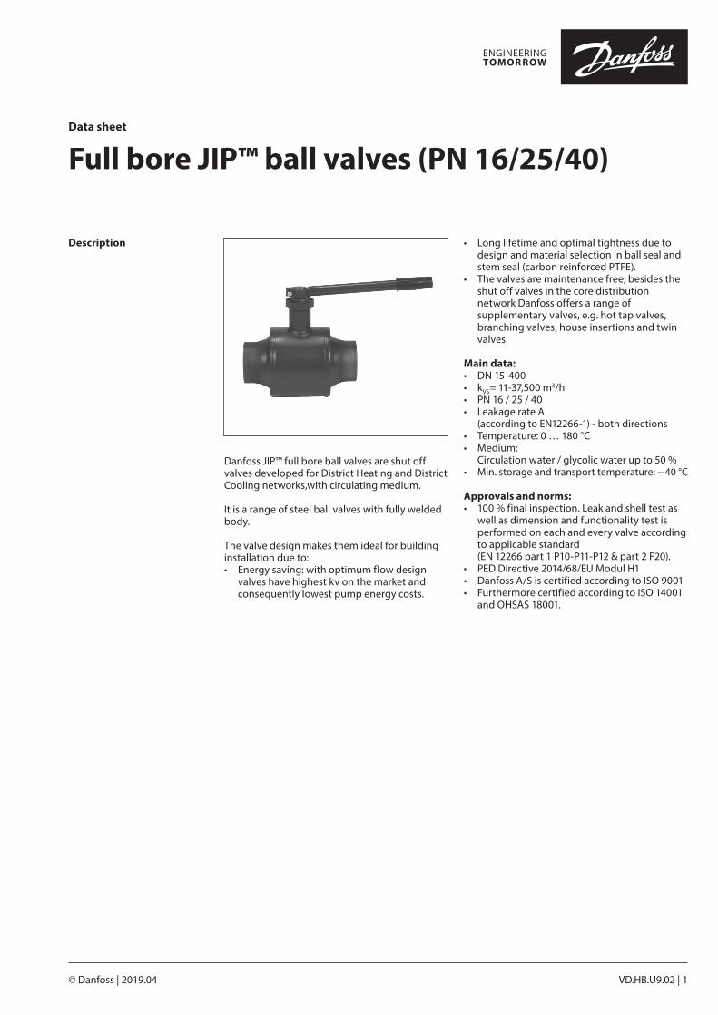
Description
Danfoss JIP™ full bore ball valves are shut off valves developed for District Heating and District Cooling networks,with circulating medium.
It is a range of steel ball valves with fully welded body.
The valve design makes them ideal for building installation due to:• Energy saving: with optimum flow design
valves have highest kv on the market and consequently lowest pump energy costs.
• Long lifetime and optimal tightness due to design and material selection in ball seal and stem seal (carbon reinforced PTFE).
• The valves are maintenance free, besides the shut off valves in the core distribution network Danfoss offers a range of supplementary valves, e.g. hot tap valves, branching valves, house insertions and twin valves.
Main data:• DN 15-400• kVS= 11-37,500 m3/h• PN 16 / 25 / 40• Leakage rate A (according to EN12266-1) - both directions• Temperature: 0 … 180 °C• Medium:
Circulation water / glycolic water up to 50 %• Min. storage and transport temperature: − 40 °C
Approvals and norms:• 100 % final inspection. Leak and shell test as
well as dimension and functionality test is performed on each and every valve according to applicable standard
(EN 12266 part 1 P10-P11-P12 & part 2 F20).• PED Directive 2014/68/EU Modul H1• Danfoss A/S is certified according to ISO 9001• Furthermore certified according to ISO 14001
and OHSAS 18001.
Data sheet Full bore JIP™ ball valves (PN 16/25/40)
2 | VD.HB.U9.02 © Danfoss | 2019.04
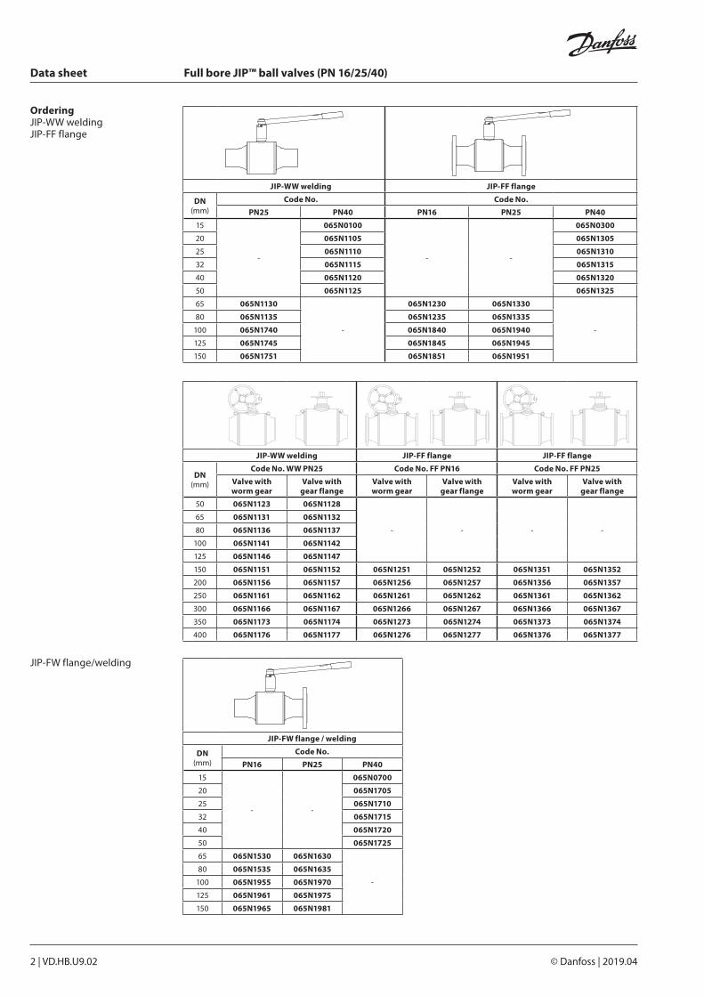
JIP-FW flange / welding
DN(mm)
Code No.
PN16 PN25 PN40
15
- -
065N0700
20 065N1705
25 065N1710
32 065N1715
40 065N1720
50 065N1725
65 065N1530 065N1630
-
80 065N1535 065N1635
100 065N1955 065N1970
125 065N1961 065N1975
150 065N1965 065N1981
OrderingJIP-WW weldingJIP-FF flange
JIP-WW welding JIP-FF flange
DN (mm)
Code No. Code No.
PN25 PN40 PN16 PN25 PN40
15
-
065N0100
- -
065N0300
20 065N1105 065N1305
25 065N1110 065N1310
32 065N1115 065N1315
40 065N1120 065N1320
50 065N1125 065N1325
65 065N1130
-
065N1230 065N1330
-
80 065N1135 065N1235 065N1335
100 065N1740 065N1840 065N1940
125 065N1745 065N1845 065N1945
150 065N1751 065N1851 065N1951
JIP-WW welding JIP-FF flange JIP-FF flange
DN (mm)
Code No. WW PN25 Code No. FF PN16 Code No. FF PN25
Valve with worm gear
Valve with gear flange
Valve with worm gear
Valve with gear flange
Valve with worm gear
Valve with gear flange
50 065N1123 065N1128
- - - -
65 065N1131 065N1132
80 065N1136 065N1137
100 065N1141 065N1142
125 065N1146 065N1147
150 065N1151 065N1152 065N1251 065N1252 065N1351 065N1352
200 065N1156 065N1157 065N1256 065N1257 065N1356 065N1357
250 065N1161 065N1162 065N1261 065N1262 065N1361 065N1362
300 065N1166 065N1167 065N1266 065N1267 065N1366 065N1367
350 065N1173 065N1174 065N1273 065N1274 065N1373 065N1374
400 065N1176 065N1177 065N1276 065N1277 065N1376 065N1377
JIP-FW flange/welding
Data sheet Full bore JIP™ ball valves (PN 16/25/40)
VD.HB.U9.02 | 3© Danfoss | 2019.04
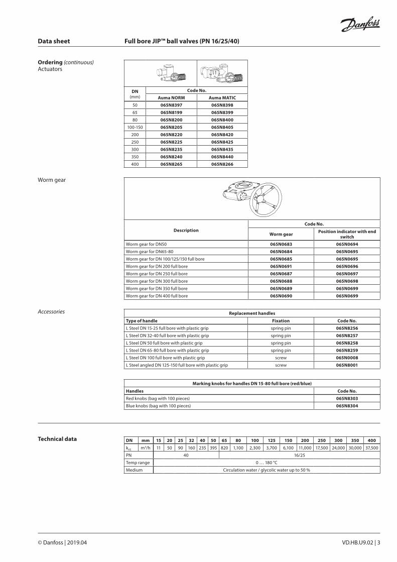
DN(mm)
Code No.
Auma NORM Auma MATIC
50 065N8397 065N8398
65 065N8199 065N8399
80 065N8200 065N8400
100-150 065N8205 065N8405
200 065N8220 065N8420
250 065N8225 065N8425
300 065N8235 065N8435
350 065N8240 065N8440
400 065N8265 065N8266
Ordering (continuous)Actuators
Worm gear
DescriptionCode No.
Worm gear Position indicator with end switch
Worm gear for DN50 065N0683 065N0694
Worm gear for DN65-80 065N0684 065N0695
Worm gear for DN 100/125/150 full bore 065N0685 065N0695
Worm gear for DN 200 full bore 065N0691 065N0696
Worm gear for DN 250 full bore 065N0687 065N0697
Worm gear for DN 300 full bore 065N0688 065N0698
Worm gear for DN 350 full bore 065N0689 065N0699
Worm gear for DN 400 full bore 065N0690 065N0699
Technical data DN mm 15 20 25 32 40 50 65 80 100 125 150 200 250 300 350 400
kVS m3/h 11 50 90 160 235 395 820 1,100 2,300 3,700 6,100 11,000 17,500 24,000 30,000 37,500
PN 40 16/25
Temp range 0 … 180 °C
Medium Circulation water / glycolic water up to 50 %
Accessories Replacement handles
Type of handle Fixation Code No.
L Steel DN 15-25 full bore with plastic grip spring pin 065N8256
L Steel DN 32-40 full bore with plastic grip spring pin 065N8257
L Steel DN 50 full bore with plastic grip spring pin 065N8258
L Steel DN 65-80 full bore with plastic grip spring pin 065N8259
L Steel DN 100 full bore with plastic grip screw 065N0008
L Steel angled DN 125-150 full bore with plastic grip screw 065N8001
Marking knobs for handles DN 15-80 full bore (red/blue)
Handles Code No.
Red knobs (bag with 100 pieces) 065N8303
Blue knobs (bag with 100 pieces) 065N8304
Data sheet Full bore JIP™ ball valves (PN 16/25/40)
4 | VD.HB.U9.02 © Danfoss | 2019.04
1 Welding end Weldable steel* e.g. P235GH
1A Flange Weldable steel* e.g. P235GH
2 Shell Weldable steel* e.g. P235GH
3 Ball seal retainer Steel P235
4 Ball Stainless steel
5 Ball seal Carbon reinforced PTFE
6 Stem Stainless steel
7 Washer Carbon reinforced PTFE
8 Stem sealing Carbon reinforced PTFE
9 Compression ring Steel
10 Compression nut Steel
11 Packing box Weldable steel* e.g. P235GH
12 Pin Spring steel
13 Handle Steel
DN 15-65 with handle
1 Welding end Weldable steel* e.g. P235GH
1A Flange Weldable steel* e.g. P235GH
2 Guiding pipe Weldable steel* e.g. P235GH
3 Shell Weldable steel* e.g. P235GH
4 Ball seal retainer Steel P235
5 Ball Stainless steel
6 Pipe insert Stainless steel
7 Ball seal Carbon reinforced PTFE
8 Disc spring Domex 650 MC
9 Stem Stainless steel
10 Washer Carbon reinforced PTFE
11 Packing box Weldable steel* e.g. P235GH
12 Stem sealing Carbon reinforced PTFE
13 Compression ring Steel
14 Compression nut Steel
15 Retaining ring Stainless steel
16 Key Steel
DN 50-400 with gear flange
1 Welding end Weldable steel* e.g. P235GH
1A Flange Weldable steel* e.g. P235GH
2 Shell Weldable steel* e.g. P235GH
3 Ball seal retainer Steel P235
4 Ball Stainless steel
5 Pipe insert Stainless steel
6 Ball seal Carbon reinforced PTFE
7 Disc spring Domex 650 MC
8 Stem Stainless steel
9 Washer Carbon reinforced PTFE
10 Packing box Weldable steel* e.g. P235GH
11 Stem sealing Carbon reinforced PTFE
12 Compression ring Steel
13 Compression nut Steel
14 Retaining ring Stainless steel
15 Handle Steel
16 Guiding pipe Weldable steel* e.g. P235GH
DN 80-150 with handle
DN80 handle
Design&material
Data sheet Full bore JIP™ ball valves (PN 16/25/40)
VD.HB.U9.02 | 5© Danfoss | 2019.04
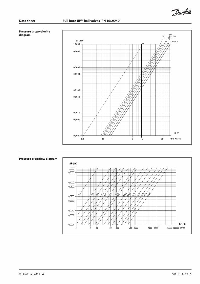
∆P (bar)
1 5 50 500 5000 5000010 100 1000 10000 100000 m3/h
1,0000
0,1000
0,0100
0,0010
0,0001
0,0005
0,0050
0,0500
0,5000
DN15
DN20
DN150
DN400
DN300
DN200
DN250DN40
DN50
DN80
DN100DN65
DN125DN25
DN32
JiP FB
15 20
40
80 100
150
200/250
30050
65125
25
32
1,0000
0,1000
0,0100
0,0010
0,0001
0,0005
0,0050
0,0500
0,5000
0,1 0,5 5 50101 m/sec
∆P (bar)
JiP FB
DN
100
400
Pressure drop/velocity diagram
Pressure drop/flow diagram
Data sheet Full bore JIP™ ball valves (PN 16/25/40)
6 | VD.HB.U9.02 © Danfoss | 2019.04
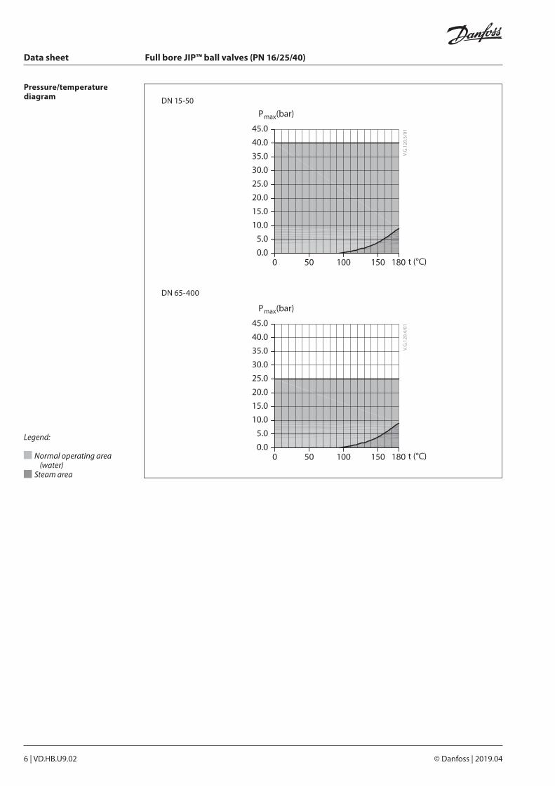
Pressure/temperature diagram DN 15-50
DN 65-400
Legend:
Normal operating area (water)
Steam area
Data sheet Full bore JIP™ ball valves (PN 16/25/40)
VD.HB.U9.02 | 7© Danfoss | 2019.04
ØD
t
F
Hh
ØB
ØA
HgØC
L
E
G3
O
G1
G2
S
L
ØC H
ØAØB
ØD
F
t
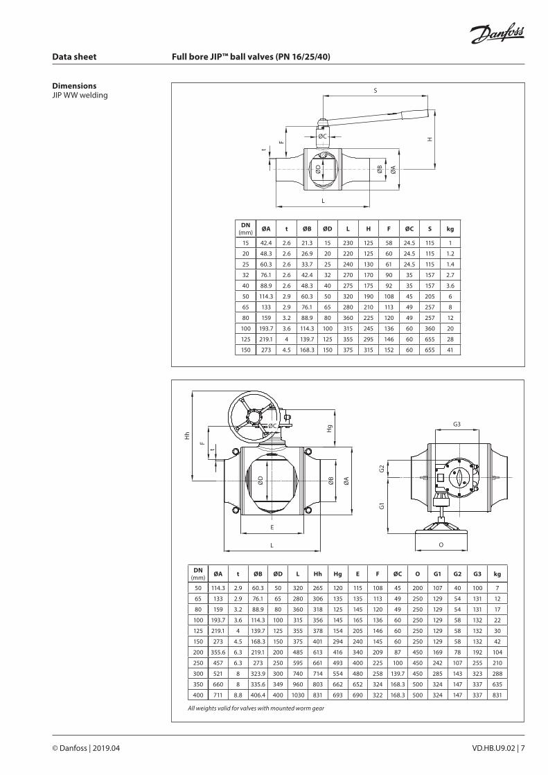
DimensionsJIP WW welding
DN (mm) ØA t ØB ØD L H F ØC S kg
15 42.4 2.6 21.3 15 230 125 58 24.5 115 1
20 48.3 2.6 26.9 20 220 125 60 24.5 115 1.2
25 60.3 2.6 33.7 25 240 130 61 24.5 115 1.4
32 76.1 2.6 42.4 32 270 170 90 35 157 2.7
40 88.9 2.6 48.3 40 275 175 92 35 157 3.6
50 114.3 2.9 60.3 50 320 190 108 45 205 6
65 133 2.9 76.1 65 280 210 113 49 257 8
80 159 3.2 88.9 80 360 225 120 49 257 12
100 193.7 3.6 114.3 100 315 245 136 60 360 20
125 219.1 4 139.7 125 355 295 146 60 655 28
150 273 4.5 168.3 150 375 315 152 60 655 41
DN (mm) ØA t ØB ØD L Hh Hg E F ØC O G1 G2 G3 kg
50 114.3 2.9 60.3 50 320 265 120 115 108 45 200 107 40 100 7
65 133 2.9 76.1 65 280 306 135 135 113 49 250 129 54 131 12
80 159 3.2 88.9 80 360 318 125 145 120 49 250 129 54 131 17
100 193.7 3.6 114.3 100 315 356 145 165 136 60 250 129 58 132 22
125 219.1 4 139.7 125 355 378 154 205 146 60 250 129 58 132 30
150 273 4.5 168.3 150 375 401 294 240 145 60 250 129 58 132 42
200 355.6 6.3 219.1 200 485 613 416 340 209 87 450 169 78 192 104
250 457 6.3 273 250 595 661 493 400 225 100 450 242 107 255 210
300 521 8 323.9 300 740 714 554 480 258 139.7 450 285 143 323 288
350 660 8 335.6 349 960 803 662 652 324 168.3 500 324 147 337 635
400 711 8.8 406.4 400 1030 831 693 690 322 168.3 500 324 147 337 831
All weights valid for valves with mounted worm gear
Data sheet Full bore JIP™ ball valves (PN 16/25/40)
8 | VD.HB.U9.02 © Danfoss | 2019.04
S
L
ØC H
ØA DF
ØD
F
tI
G3
O
G1
G2
ØD
IHh
F
DF
HgØC
L
E
ØA
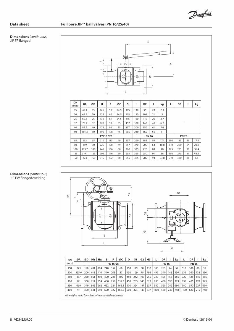
Dimensions (continuous) JIP FF flanged
DN (mm) ØA ØD H F ØC S L DF I kg L DF I kg
15 42.4 15 125 58 24.5 115 130 95 23 2.3
-
20 48.3 20 125 60 24.5 115 150 105 21 3
25 60.3 25 130 61 24.5 115 160 115 20 3.7
32 76.1 32 170 90 35 157 180 140 40 6.2
40 88.9 40 175 92 35 157 200 150 41 7.4
50 114.3 50 190 108 45 205 230 165 56 11
PN 16 / 25 PN 16 PN 25
65 133 65 210 113 49 257 290 185 59 17.1 290 185 59 17.5
80 159 80 225 120 49 257 370 200 64 18.8 310 200 64 20.2
100 193.7 100 245 136 60 360 325 220 83 28 325 235 76 31.4
125 219.1 125 295 146 60 655 365 250 91 38 490 270 81 43.4
150 273 150 315 152 60 655 385 285 94 53.8 510 300 86 61
Dimensions (continuous)JIP FW flanged/welding
DN (mm)
ØA ØD Hh Hg E F ØC O G1 G2 G3 L DF I kg L DF I kg
PN 16/25 PN 16 PN 25
150 273 150 401 294 240 152 60 250 129 58 132 385 285 94 57 510 300 86 57
200 355.6 200 613 416 340 209 87 450 169 78 192 495 340 148 136 635 360 138 136
250 457 250 661 493 400 225 100 450 242 107 255 720 405 158 256 720 425 149 266
300 521 300 714 554 480 258 139.7 450 285 143 323 835 460 190 329 835 485 178 329
350 660 349 803 662 652 324 168.3 500 324 147 337 980 520 242 690 980 550 227 690
400 711 400 831 693 690 322 168.3 500 324 147 337 1100 580 235 748 1100 620 215 748
All weights valid for valves with mounted worm gear

Data sheet Full bore JIP™ ball valves (PN 16/25/40)
VD.HB.U9.02 | 9© Danfoss | 2019.04
S
L
ØC H
ØA DF
ØD
F
ØB
I
Dimensions (continuous)JIP FW flanged/welding
DN (mm) ØA ØB H F ØC S L DF I kg L DF I kg
15 42.4 15 125 58 24.5 115 180 95 23 1.6
-
20 48.3 20 125 60 24.5 115 185 105 21 2.1
25 60.3 25 130 61 24.5 115 200 115 20 2.6
32 76.1 32 170 90 35 157 230 140 40 4.5
40 88.9 40 175 92 35 157 235 150 41 5.6
50 114.3 50 190 108 45 205 275 165 56 8.5
PN 16 / 25 PN 16 PN 25
65 133 65 210 113 49 257 285 185 59 10.7 285 185 59 10.7
80 159 80 225 120 49 257 365 200 64 15.8 335 200 64 15.9
100 193.7 100 245 136 60 360 320 220 83 22.5 320 235 76 24
125 219.1 125 295 146 60 655 360 250 91 32.5 360 270 81 35.2
150 273 150 315 152 60 655 380 285 94 47.1 380 300 86 50.9
Data sheet Full bore JIP™ ball valves (PN 16/25/40)
10 | VD.HB.U9.02 © Danfoss | 2019.04
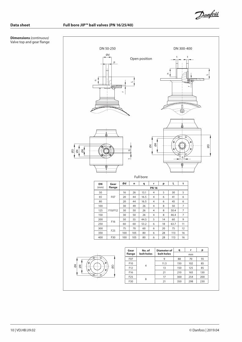
Ød
n
r
L
p
ØK
ØR
ØD q
t
ØD
q
ØK ØR
n L
r
t t
Full bore
Dimensions (continuous)Valve top and gear flange
Open position
DN 50-250 DN 300-400
ØDØK
ØR
Gear flange
No. of bolt holes
Diameter of bolt holes
q r p
mm
F07
4
9 88 70 55
F10 11.5 150 102 85
F12 13 150 125 85
F16 21 210 165 130
F258
17 300 254 200
F30 21 350 298 230
DN (mm)
Gear flange
Ød n q r p L t
PN 16
50
F07
16 26 13.1 4 5 30 5
65 20 44 16.5 4 6 41 6
80 20 44 16.5 4 6 45 6
100
F10/F12
30 49 26 4 8 50 7
125 30 50 26 4 8 50.4 7
150 30 50 26 4 8 46.4 7
200F16
50 55 44.5 5 14 60 9
250 60 60 53.2 6 18 63.7 11
300F25
75 70 60 6 20 75 12
350 100 105 80 6 28 113 16
400 F30 100 105 80 6 28 113 16
Data sheet Full bore JIP™ ball valves (PN 16/25/40)
VD.HB.U9.02 | 11© Danfoss | 2019.04
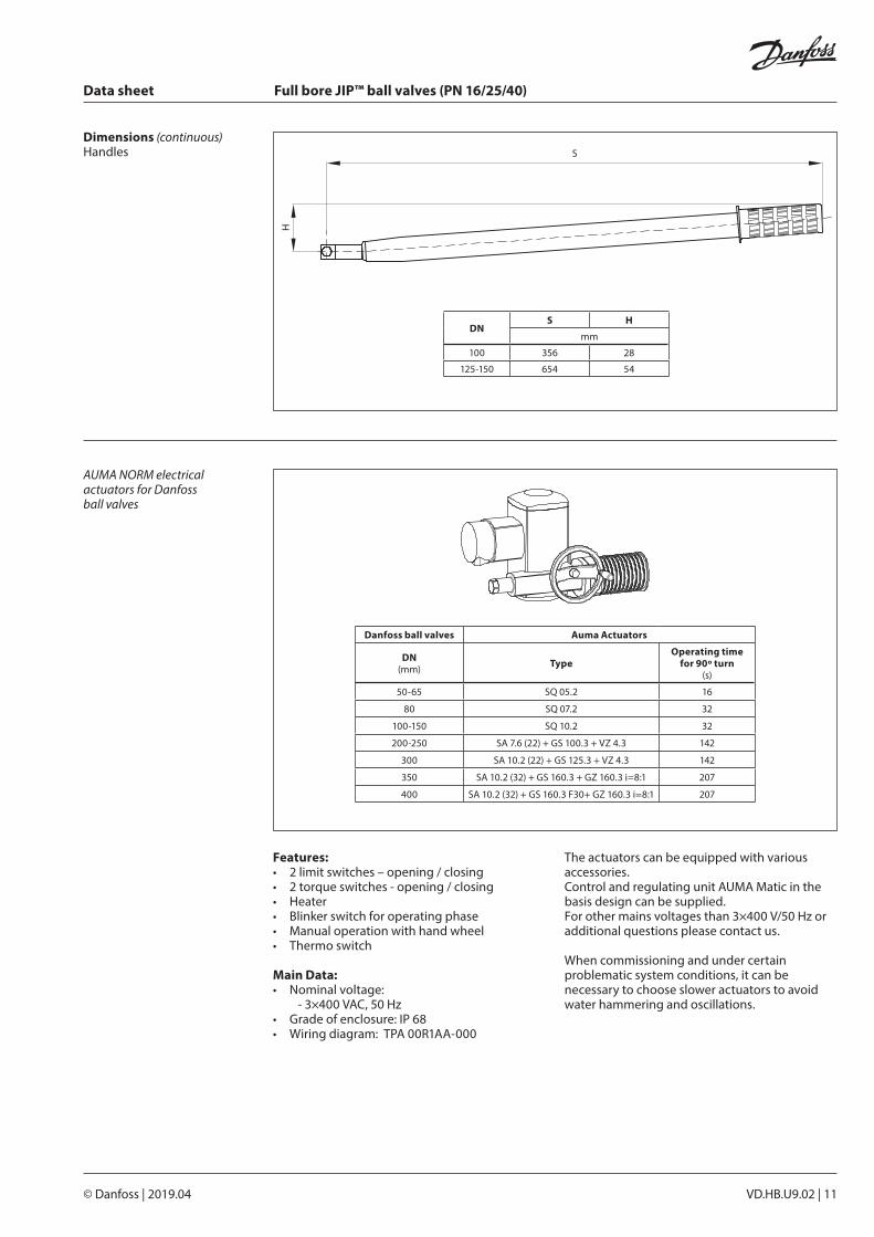
H
S
AUMA NORM electrical actuators for Danfoss ball valves
Features:• 2 limit switches – opening / closing• 2 torque switches - opening / closing• Heater• Blinker switch for operating phase• Manual operation with hand wheel• Thermo switch
Main Data:• Nominal voltage:
- 3×400 VAC, 50 Hz• Grade of enclosure: IP 68• Wiring diagram: TPA 00R1AA-000
The actuators can be equipped with various accessories. Control and regulating unit AUMA Matic in the basis design can be supplied. For other mains voltages than 3×400 V/50 Hz or additional questions please contact us.
When commissioning and under certain problematic system conditions, it can be necessary to choose slower actuators to avoid water hammering and oscillations.
DNS H
mm
100 356 28
125-150 654 54
Danfoss ball valves Auma Actuators
DN(mm) Type
Operating timefor 90º turn
(s)
50-65 SQ 05.2 16
80 SQ 07.2 32
100-150 SQ 10.2 32
200-250 SA 7.6 (22) + GS 100.3 + VZ 4.3 142
300 SA 10.2 (22) + GS 125.3 + VZ 4.3 142
350 SA 10.2 (32) + GS 160.3 + GZ 160.3 i=8:1 207
400 SA 10.2 (32) + GS 160.3 F30+ GZ 160.3 i=8:1 207
Dimensions (continuous)Handles

© Danfoss | DHS-SRMT/SI | 2019.0412 | VD.HB.U9.02
Data sheet Full bore JIP™ ball valves (PN 16/25/40)