front cover implementing and testing soa on ibm … · front cover implementing and testing soa on...
TRANSCRIPT
ibm.com/redbooks
Front cover
Implementing and Testing SOA on IBM System zA Real Customer Case
Christian MatthysMathias Bonnard
Sylvie LemarieyJean-Louis Pimont
Alain Roessle
Using SOA to add business value to existing systems
Rejuvenating old applications for a modernized infrastructure
Understanding the cohabitation and migration process

International Technical Support Organization
Implementing and Testing SOA on IBM System z: A Real Customer Case
August 2007
SG24-7502-00

© Copyright International Business Machines Corporation 2007. All rights reserved.Note to U.S. Government Users Restricted Rights -- Use, duplication or disclosure restricted by GSA ADP ScheduleContract with IBM Corp.
First Edition (August 2007)
This edition applies mainly to IBM WebSphere Application Server V6 and WebSphere Business Integration Server Foundation V6. It also involves WebSphere Process Server for z/OS Version 6 (5655-N53) and WebSphere Enterprise Service Bus for z/OS Version 6 (5655-R15).
Note: Before using this information and the product it supports, read the information in “Notices” on page v.
Contents
Notices . . . . . . . . . . . . . . . . . . . . . . . . . . . . . . . . . . . . . . . . . . . . . . . . . . . . . . . . . . . . . . . . . .vTrademarks . . . . . . . . . . . . . . . . . . . . . . . . . . . . . . . . . . . . . . . . . . . . . . . . . . . . . . . . . . . . . . vi
Preface . . . . . . . . . . . . . . . . . . . . . . . . . . . . . . . . . . . . . . . . . . . . . . . . . . . . . . . . . . . . . . . . . viiThe team that wrote this book . . . . . . . . . . . . . . . . . . . . . . . . . . . . . . . . . . . . . . . . . . . . . . . viiiBecome a published author . . . . . . . . . . . . . . . . . . . . . . . . . . . . . . . . . . . . . . . . . . . . . . . . . . ixComments welcome. . . . . . . . . . . . . . . . . . . . . . . . . . . . . . . . . . . . . . . . . . . . . . . . . . . . . . . . ix
Chapter 1. Customer business needs and architectural choices. . . . . . . . . . . . . . . . . . 11.1 The customer vision and constraints. . . . . . . . . . . . . . . . . . . . . . . . . . . . . . . . . . . . . . . . 2
1.1.1 From silos to composite applications . . . . . . . . . . . . . . . . . . . . . . . . . . . . . . . . . . . 21.1.2 The methodology aspects . . . . . . . . . . . . . . . . . . . . . . . . . . . . . . . . . . . . . . . . . . . . 61.1.3 A project-leading approach that favors reuse . . . . . . . . . . . . . . . . . . . . . . . . . . . . 101.1.4 The customer environment and business context. . . . . . . . . . . . . . . . . . . . . . . . . 171.1.5 The current IT application . . . . . . . . . . . . . . . . . . . . . . . . . . . . . . . . . . . . . . . . . . . 231.1.6 The future system . . . . . . . . . . . . . . . . . . . . . . . . . . . . . . . . . . . . . . . . . . . . . . . . . 24
1.2 The architecture choices . . . . . . . . . . . . . . . . . . . . . . . . . . . . . . . . . . . . . . . . . . . . . . . . 251.2.1 A target vision that conforms to the SOA-BPM model . . . . . . . . . . . . . . . . . . . . . 271.2.2 An iterative development and progressive deployment . . . . . . . . . . . . . . . . . . . . 281.2.3 SOA-BPM vision of the business processes. . . . . . . . . . . . . . . . . . . . . . . . . . . . . 291.2.4 SOA-BPM vision of the Create_Order process. . . . . . . . . . . . . . . . . . . . . . . . . . . 30
1.3 From the architecture to the prototype . . . . . . . . . . . . . . . . . . . . . . . . . . . . . . . . . . . . . 331.3.1 SOA implemented with the integration platform from WebSphere Version 6 . . . . 331.3.2 Experimentation of the WebSphere Business Integration platform. . . . . . . . . . . . 381.3.3 System z as the target platform . . . . . . . . . . . . . . . . . . . . . . . . . . . . . . . . . . . . . . 401.3.4 Comparison between the SAP and WBI V6 mock-ups . . . . . . . . . . . . . . . . . . . . . 501.3.5 Two implementations of the SOA-BPM architecture. . . . . . . . . . . . . . . . . . . . . . . 511.3.6 The WBI V6 mock-up . . . . . . . . . . . . . . . . . . . . . . . . . . . . . . . . . . . . . . . . . . . . . . 551.3.7 The SAP mock-up. . . . . . . . . . . . . . . . . . . . . . . . . . . . . . . . . . . . . . . . . . . . . . . . . 62
1.4 Results and benefits . . . . . . . . . . . . . . . . . . . . . . . . . . . . . . . . . . . . . . . . . . . . . . . . . . . 71
Chapter 2. Application design . . . . . . . . . . . . . . . . . . . . . . . . . . . . . . . . . . . . . . . . . . . . . 732.1 System context and functionalities . . . . . . . . . . . . . . . . . . . . . . . . . . . . . . . . . . . . . . . . 74
2.1.1 The system context . . . . . . . . . . . . . . . . . . . . . . . . . . . . . . . . . . . . . . . . . . . . . . . . 742.1.2 The functionalities of the application . . . . . . . . . . . . . . . . . . . . . . . . . . . . . . . . . . . 75
2.2 Architectural model . . . . . . . . . . . . . . . . . . . . . . . . . . . . . . . . . . . . . . . . . . . . . . . . . . . . 762.3 Components of the application . . . . . . . . . . . . . . . . . . . . . . . . . . . . . . . . . . . . . . . . . . . 78
2.3.1 The processes implemented into the WebSphere Process Server. . . . . . . . . . . . 782.3.2 Data access . . . . . . . . . . . . . . . . . . . . . . . . . . . . . . . . . . . . . . . . . . . . . . . . . . . . . 792.3.3 The Create_Order process . . . . . . . . . . . . . . . . . . . . . . . . . . . . . . . . . . . . . . . . . . 792.3.4 The Register_Order subprocess. . . . . . . . . . . . . . . . . . . . . . . . . . . . . . . . . . . . . . 802.3.5 Implementation of the WMS simulator . . . . . . . . . . . . . . . . . . . . . . . . . . . . . . . . . 822.3.6 The links between the subsystems . . . . . . . . . . . . . . . . . . . . . . . . . . . . . . . . . . . . 83
2.4 Flow of the application implemented on z/OS. . . . . . . . . . . . . . . . . . . . . . . . . . . . . . . . 83
Chapter 3. Implementation of the WebSphere Process Server V6 mock-up . . . . . . . . 853.1 Description of the WBI V6 mock-up . . . . . . . . . . . . . . . . . . . . . . . . . . . . . . . . . . . . . . . 86
3.1.1 The Manage Order system . . . . . . . . . . . . . . . . . . . . . . . . . . . . . . . . . . . . . . . . . . 863.1.2 The Business Logic system . . . . . . . . . . . . . . . . . . . . . . . . . . . . . . . . . . . . . . . . . 87
© Copyright IBM Corp. 2007. All rights reserved. iii
3.1.3 The Warehouse Management system . . . . . . . . . . . . . . . . . . . . . . . . . . . . . . . . . 883.1.4 The Generate Order system . . . . . . . . . . . . . . . . . . . . . . . . . . . . . . . . . . . . . . . . . 883.1.5 Summary. . . . . . . . . . . . . . . . . . . . . . . . . . . . . . . . . . . . . . . . . . . . . . . . . . . . . . . . 88
3.2 Infrastructure and configuration . . . . . . . . . . . . . . . . . . . . . . . . . . . . . . . . . . . . . . . . . . 893.2.1 The hardware and software infrastructure . . . . . . . . . . . . . . . . . . . . . . . . . . . . . . 893.2.2 The WebSphere Process Server configuration. . . . . . . . . . . . . . . . . . . . . . . . . . . 903.2.3 Service Integration Bus. . . . . . . . . . . . . . . . . . . . . . . . . . . . . . . . . . . . . . . . . . . . . 98
Chapter 4. Mock-up extensions . . . . . . . . . . . . . . . . . . . . . . . . . . . . . . . . . . . . . . . . . . . 1094.1 BPM extensions: A long-running process with manual tasks . . . . . . . . . . . . . . . . . . . 110
4.1.1 Adding a human task to the automatic process . . . . . . . . . . . . . . . . . . . . . . . . . 1104.1.2 Extended process modeling with the WebSphere Business Modeler. . . . . . . . . 1124.1.3 Adding a business rule for order checking . . . . . . . . . . . . . . . . . . . . . . . . . . . . . 1134.1.4 Manual task management with the MyTasks portlet . . . . . . . . . . . . . . . . . . . . . . 114
4.2 Monitoring business processes using WebSphere Business Monitor. . . . . . . . . . . . . 1164.3 XForms extensions: Placing orders using Workplace Forms . . . . . . . . . . . . . . . . . . . 1184.4 B2x portal extensions: Portlets personalized by user profiles . . . . . . . . . . . . . . . . . . . 120
4.4.1 Offering personalized access to users . . . . . . . . . . . . . . . . . . . . . . . . . . . . . . . . 1214.4.2 Exposing Web services with IBM WebSphere Portlet Factory . . . . . . . . . . . . . . 124
Chapter 5. From the current architecture to the SOA: A migration experience . . . . 1275.1 A generic solution to eradicate the obsolete language . . . . . . . . . . . . . . . . . . . . . . . . 128
5.1.1 Enterprise Generation Language overview. . . . . . . . . . . . . . . . . . . . . . . . . . . . . 1285.1.2 Solutions to eradicate the obsolete language . . . . . . . . . . . . . . . . . . . . . . . . . . . 1305.1.3 Automating the conversion to EGL . . . . . . . . . . . . . . . . . . . . . . . . . . . . . . . . . . . 1305.1.4 Combining conversion and rewriting . . . . . . . . . . . . . . . . . . . . . . . . . . . . . . . . . . 1315.1.5 Three classes of applications . . . . . . . . . . . . . . . . . . . . . . . . . . . . . . . . . . . . . . . 1315.1.6 Valorizing an obsolete language system. . . . . . . . . . . . . . . . . . . . . . . . . . . . . . . 133
5.2 Target architecture of the new system . . . . . . . . . . . . . . . . . . . . . . . . . . . . . . . . . . . . 1355.2.1 Architectural principles of the prototype . . . . . . . . . . . . . . . . . . . . . . . . . . . . . . . 1355.2.2 Complete architecture of the new system. . . . . . . . . . . . . . . . . . . . . . . . . . . . . . 1375.2.3 Proposed development plan for the OM subproject . . . . . . . . . . . . . . . . . . . . . . 142
Appendix A. Performance tests . . . . . . . . . . . . . . . . . . . . . . . . . . . . . . . . . . . . . . . . . . . 145
Abbreviations and acronyms . . . . . . . . . . . . . . . . . . . . . . . . . . . . . . . . . . . . . . . . . . . . . 149
Related publications . . . . . . . . . . . . . . . . . . . . . . . . . . . . . . . . . . . . . . . . . . . . . . . . . . . . 151IBM Redbooks . . . . . . . . . . . . . . . . . . . . . . . . . . . . . . . . . . . . . . . . . . . . . . . . . . . . . . . . . . 151Online resources . . . . . . . . . . . . . . . . . . . . . . . . . . . . . . . . . . . . . . . . . . . . . . . . . . . . . . . . 151How to get IBM Redbooks . . . . . . . . . . . . . . . . . . . . . . . . . . . . . . . . . . . . . . . . . . . . . . . . . 152Help from IBM . . . . . . . . . . . . . . . . . . . . . . . . . . . . . . . . . . . . . . . . . . . . . . . . . . . . . . . . . . 152
Index . . . . . . . . . . . . . . . . . . . . . . . . . . . . . . . . . . . . . . . . . . . . . . . . . . . . . . . . . . . . . . . . . 153
iv Implementing and Testing SOA on IBM System z: A Real Customer Case

Notices
This information was developed for products and services offered in the U.S.A.
IBM may not offer the products, services, or features discussed in this document in other countries. Consult your local IBM representative for information on the products and services currently available in your area. Any reference to an IBM product, program, or service is not intended to state or imply that only that IBM product, program, or service may be used. Any functionally equivalent product, program, or service that does not infringe any IBM intellectual property right may be used instead. However, it is the user's responsibility to evaluate and verify the operation of any non-IBM product, program, or service.
IBM may have patents or pending patent applications covering subject matter described in this document. The furnishing of this document does not give you any license to these patents. You can send license inquiries, in writing, to: IBM Director of Licensing, IBM Corporation, North Castle Drive, Armonk, NY 10504-1785 U.S.A.
The following paragraph does not apply to the United Kingdom or any other country where such provisions are inconsistent with local law: INTERNATIONAL BUSINESS MACHINES CORPORATION PROVIDES THIS PUBLICATION "AS IS" WITHOUT WARRANTY OF ANY KIND, EITHER EXPRESS OR IMPLIED, INCLUDING, BUT NOT LIMITED TO, THE IMPLIED WARRANTIES OF NON-INFRINGEMENT, MERCHANTABILITY OR FITNESS FOR A PARTICULAR PURPOSE. Some states do not allow disclaimer of express or implied warranties in certain transactions, therefore, this statement may not apply to you.
This information could include technical inaccuracies or typographical errors. Changes are periodically made to the information herein; these changes will be incorporated in new editions of the publication. IBM may make improvements and/or changes in the product(s) and/or the program(s) described in this publication at any time without notice.
Any references in this information to non-IBM Web sites are provided for convenience only and do not in any manner serve as an endorsement of those Web sites. The materials at those Web sites are not part of the materials for this IBM product and use of those Web sites is at your own risk.
IBM may use or distribute any of the information you supply in any way it believes appropriate without incurring any obligation to you.
Information concerning non-IBM products was obtained from the suppliers of those products, their published announcements or other publicly available sources. IBM has not tested those products and cannot confirm the accuracy of performance, compatibility or any other claims related to non-IBM products. Questions on the capabilities of non-IBM products should be addressed to the suppliers of those products.
This information contains examples of data and reports used in daily business operations. To illustrate them as completely as possible, the examples include the names of individuals, companies, brands, and products. All of these names are fictitious and any similarity to the names and addresses used by an actual business enterprise is entirely coincidental.
COPYRIGHT LICENSE:
This information contains sample application programs in source language, which illustrate programming techniques on various operating platforms. You may copy, modify, and distribute these sample programs in any form without payment to IBM, for the purposes of developing, using, marketing or distributing application programs conforming to the application programming interface for the operating platform for which the sample programs are written. These examples have not been thoroughly tested under all conditions. IBM, therefore, cannot guarantee or imply reliability, serviceability, or function of these programs.
© Copyright IBM Corp. 2007. All rights reserved. v
Trademarks
The following terms are trademarks of the International Business Machines Corporation in the United States, other countries, or both:
AIX®Cloudscape™CICS®developerWorks®Domino®DB2®ESCON®HiperSockets™IBM®IMS™
Lotus Notes®Lotus®Notes®OS/390®Parallel Sysplex®Processor Resource/Systems
Manager™PR/SM™Rational®Redbooks®
Redbooks (logo) ®System p™System p5™System z™Tivoli®VisualAge®WebSphere®Workplace™Workplace Forms™z/OS®
The following terms are trademarks of other companies:
BAPI, ABAP, SAP, and SAP logos are trademarks or registered trademarks of SAP AG in Germany and in several other countries.
Oracle, JD Edwards, PeopleSoft, Siebel, and TopLink are registered trademarks of Oracle Corporation and/or its affiliates.
EJB, Java, JavaServer, JavaServer Pages, JDBC, JSP, J2EE, and all Java-based trademarks are trademarks of Sun Microsystems, Inc. in the United States, other countries, or both.
Microsoft, Windows, and the Windows logo are trademarks of Microsoft Corporation in the United States, other countries, or both.
UNIX is a registered trademark of The Open Group in the United States and other countries.
Linux is a trademark of Linus Torvalds in the United States, other countries, or both.
Other company, product, or service names may be trademarks or service marks of others.
vi Implementing and Testing SOA on IBM System z: A Real Customer Case
Preface
Service-oriented architecture (SOA) is one of the most important topics on the agenda of any IT person. SOA involves a new vision of how to design, develop, and manage applications. It also has new requirements when building an architecture for the underlying infrastructure.
This IBM® Redbooks® publication is the result of a project managed in the IBM European Design Center, based in Montpellier, France. The scope of the project involved helping a major worldwide customer in the automotive industry to validate and justify an SOA implementation. In particular, the customer wanted to add new business values to work with its partners, by adding new data models. It also wanted to modernize an infrastructure, by adding new Internet interfaces. The customer faced the need to eradicate an obsolete programming language. Furthermore, it wanted to build a smooth migration path, with as few risks and costs as possible.
The thought, planning, and architecture of the new system, which included integration of the SOA concepts, was built by the customer with the participation of Atos Origin, a leading international IT services provider. The existing customer IT infrastructure was already built around UNIX® systems, IBM System z™, non-IBM clusters, SAP® solutions, 3270 screens, IMS™-DL/I databases, and specific code. SOA was the right solution to connect this existing environment to new components using Java™, Web services, and DB2® in particular.
Using tests and prototypes, the IBM Design Center was able to validate the following areas in the project:
� The architecture, with its methodology and its technical components
� The basic performance aspects, leading to a solution based on WebSphere® on the System z platform
� The migration process, to guarantee management of the risks
This book explores the business needs and the architectural choices that were faced by the customer. It describes the mock-ups and prototypes, provides performance numbers that were used to validate the decisions, and explains how they were implemented. It also suggests a generic and riskless solution to eradicate the obsolete programming language.
© Copyright IBM Corp. 2007. All rights reserved. vii
The team that wrote this bookThis book was produced by a team of specialists from around the world working for the International Technical Support Organization (ITSO), Poughkeepsie Center.
Christian Matthys is a Consulting IBM IT Specialist who has spent more than 25 years with IBM as a System Engineer working with large, mainframe-oriented customers in France. He spent three years as an ITSO project leader on assignment in Poughkeepsie, NY. In 2000, he joined the EMEA Design Center for On Demand Business in the Products and Solutions Support Center (PSSC), helping customer projects exploit leading edge technologies. Christian works as a project leader for the Poughkeepsie ITSO Center, leading and supporting residencies from his base in the PSSC in France.
Mathias Bonnard is a consultant architect working for Atos Origin in France. He has more than 15 years of experience working with different clients on the deployment of e-commerce, portal, and SOA applications. His area of expertise includes J2EE™, Web services, SOA, Web 2.0, Web Content Management, and search engines. Mathias graduated in 1989 from the Ecole Nationale Supérieure des Telecommunications.
Sylvie Lemariey is an architect in the European Design Center in Montpellier, France. She currently help customers to extend their core applications to new technologies. Sylvie has more than 20 years of experience working for Software Group and ITS around middleware on z/OS®.
Jean-Louis Pimont is a senior architect working for Atos Origin in France. He currently works as an IT architect for large renewal projects that aim to modernize information systems using the SOA approach and its related technologies. His area of expertise includes operating systems, transactions monitoring, network protocols, middleware and technical development in assembler, Cobol, PLI, C, and Java. Jean-Louis has more than 30 years of experience,
Important: This book describes a customer experience that already has its own methodology, IT habits, and constraints. This book does not present theory about how to implement an SOA. It describes the one customer’s actual implementation of the SOA concepts in an existing IT production environment.
In particular, you may find interest in the following documentation, which describes the concepts of SOA and solutions for using an SOA:
� Building Composite Applications, SG24-7367
� Patterns: SOA Design using WebSphere Message Broker and WebSphere ESB, SG24-7369
� Patterns: SOA Foundation - Business Process Management Scenario, SG24-7234
� Patterns: SOA Foundation Service Creation Scenario, SG24-7240
� Production Topologies for WebSphere Process Server and WebSphere ESB V6, SG24-7413
� The Role of IBM System z In the Design of a Service Oriented Architecture, REDP-4190SOA Transition Scenarios for the IBM z/OS Platform, SG24-7331
� The Value of the IBM System z and z/OS in Service-Oriented Architecture, REDP-4152z/OS Getting Started: WebSphere Process Server and WebSphere Enterprise Service Bus V6, SG24-7378
� z/OS Technical Overview: WebSphere Process Server and WebSphere Enterprise Service Bus, REDP-4196
viii Implementing and Testing SOA on IBM System z: A Real Customer Case
mainly in the automotive industry, and has been working on IBM mainframes since 1970. He holds a degree from the Institut d’Informatique d’Entreprise in Paris, France.
Alain Roessle is an IT Architect for the IBM Design Center, in Montpellier, France. For the last two years, Alain has worked on SOA projects. His areas of expertise include WebSphere, CICS®, DB2, and Parallel Sysplex®. Before joining IBM in 2000, he worked for a large distribution company for 20 years.
A special thanks to Didier Romelot, an SOA and Java expert from the customer. Without him, the mock-up and prototype would not have been done.
Thanks to the following people for their contributions to this project:
Jean-Luc LepesantIBM PSSC
Laurent SauzetAtos Origin
Become a published authorJoin us for a two- to six-week residency program! Help write an IBM Redbooks publication that deals with specific products or solutions, while getting hands-on experience with leading-edge technologies. You will have the opportunity to team with IBM technical professionals, Business Partners, and Clients.
Your efforts will help increase product acceptance and customer satisfaction. As a bonus, you will develop a network of contacts in IBM development labs, and increase your productivity and marketability.
Find out more about the residency program, browse the residency index, and apply online at:
ibm.com/redbooks/residencies.html
Comments welcomeYour comments are important to us!
We want our IBM Redbooks publications to be as helpful as possible. Send us your comments about this or other IBM Redbooks publications in one of the following ways:
� Use the online Contact us review redbook form found at:
ibm.com/redbooks
� Send your comments in an e-mail to:
� Mail your comments to:
IBM Corporation, International Technical Support OrganizationDept. HYTD Mail Station P0992455 South RoadPoughkeepsie, NY 12601-5400
Preface ix

x Implementing and Testing SOA on IBM System z: A Real Customer Case
Chapter 1. Customer business needs and architectural choices
In this chapter, we explain how the customer applied the service-oriented architecture (SOA) to combine the latest and the most beneficial technologies with some existing and still valuable components.
� In 1.1, “The customer vision and constraints” on page 2, we highlight the necessity to promote a transversal approach to federate several disparate systems. We also discuss the methodology and the valorization of the existing systems. We describe the limitations of the current IT infrastructure, in particular the use of an unsupported language, and the long-term customer ambition, with the addition of new business values.
� In 1.2, “The architecture choices” on page 25, we describe different ways of modernization, for example using an integration package from an ISV or writing new interfaces. The final architecture will include a mix of the existing environment (when still appropriate), the addition of new integration packages (when available), and the writing of new customized processes (when easy enough).
� In 1.3, “From the architecture to the prototype” on page 33, we discuss the available tools, solutions, and products to implement this type of architecture. In particular, we present the two mock-ups (or prototypes) that were developed by the customer.
� Finally, in 1.4, “Results and benefits” on page 71, we summarize the customer expectations of the SOA approach and the reasons to develop such prototypes before implementing the final architecture, products, and tools.
1
© Copyright IBM Corp. 2007. All rights reserved. 1
1.1 The customer vision and constraints
In this section, we highlight the complexity of the current existing applications and the necessity to put in place a transversal approach. With this new approach, the customer wants to add more business value to the information technology (IT) infrastructure.
We also discuss the promotion of the reuse of the components instead of developing or buying new components. In addition, we highlight the needs of a proven methodology to build the architecture before developing a prototype.
1.1.1 From silos to composite applications
The silos model describes the application model that was inherited from the past. The composite applications, which is one target of the SOA model, describe a transversal approach that aims to federate several disparate systems.
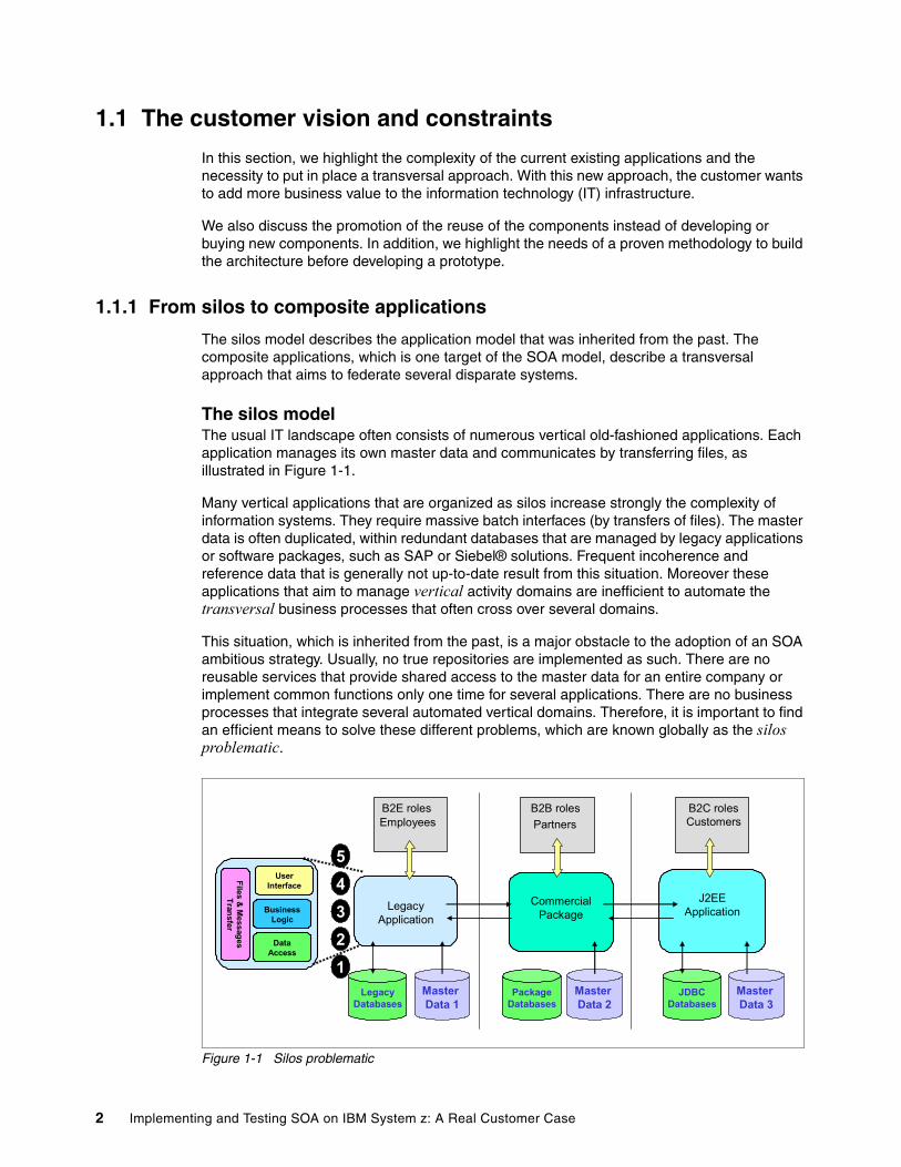
The silos modelThe usual IT landscape often consists of numerous vertical old-fashioned applications. Each application manages its own master data and communicates by transferring files, as illustrated in Figure 1-1.
Many vertical applications that are organized as silos increase strongly the complexity of information systems. They require massive batch interfaces (by transfers of files). The master data is often duplicated, within redundant databases that are managed by legacy applications or software packages, such as SAP or Siebel® solutions. Frequent incoherence and reference data that is generally not up-to-date result from this situation. Moreover these applications that aim to manage vertical activity domains are inefficient to automate the transversal business processes that often cross over several domains.
This situation, which is inherited from the past, is a major obstacle to the adoption of an SOA ambitious strategy. Usually, no true repositories are implemented as such. There are no reusable services that provide shared access to the master data for an entire company or implement common functions only one time for several applications. There are no business processes that integrate several automated vertical domains. Therefore, it is important to find an efficient means to solve these different problems, which are known globally as the silos problematic.
Figure 1-1 Silos problematic
EmployeesB2E roles
CustomersB2C roles
PartnersB2B roles
Legacy Application
CommercialPackage
J2EE Application
PackageDatabases
LegacyDatabases
JDBCDatabases
12
43
5
Master Data 1
Master Data 2
Master Data 3
Data Access
User Interface
BusinessLogic
Files & Messages
Transfer
2 Implementing and Testing SOA on IBM System z: A Real Customer Case
A transversal vision needs to be implemented to solve the silos problem, based on the following principles, shown in Figure 1-1:
� At the database level (1), promote a shared implementation of enterprise master data using modern data warehousing technologies (and tools), such as Master Data Management (MDM) and Extract Transfer and Load (ETL), to consolidate data from different source systems.
� At the business logic level (2), promote an effective reuse of existing processes that are exposed as services (assets reuse).
� At the file and message transfer level (3), promote the generalization of the interfaces in messaging mode through a common bus.
� At the business process level (4), promote an implementation of the processes that correspond to the business process management (BPM) model.
� At the user-interface level (5), promote the integration and personalization of a Web graphical user interface (GUI) through a B2x portal for example.
Composite applicationsTo solve this problem, the SOA target model and related technologies, such as BPM, Enterprise Service Bus (ESB), and a B2x portal, promote a transversal approach that aims to federate several disparate systems. By integrating existing or new applications and software packages and by sharing their common master data, new functionality can be added faster and cheaper.
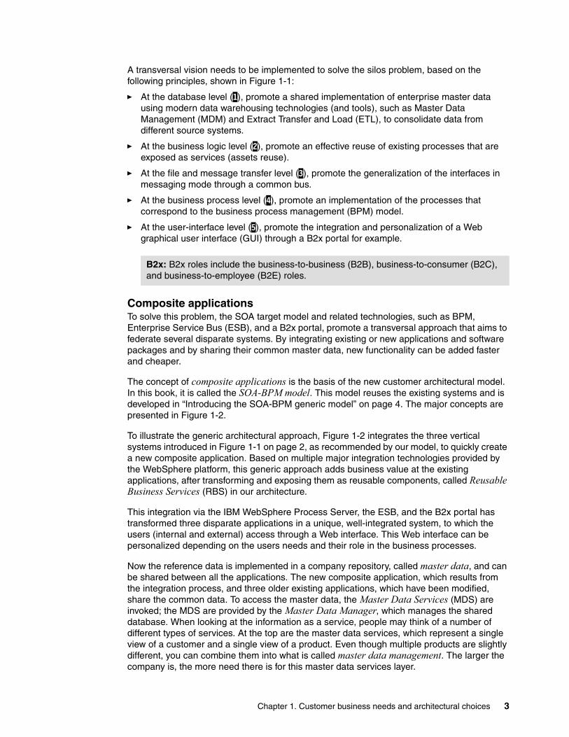
The concept of composite applications is the basis of the new customer architectural model. In this book, it is called the SOA-BPM model. This model reuses the existing systems and is developed in “Introducing the SOA-BPM generic model” on page 4. The major concepts are presented in Figure 1-2.
To illustrate the generic architectural approach, Figure 1-2 integrates the three vertical systems introduced in Figure 1-1 on page 2, as recommended by our model, to quickly create a new composite application. Based on multiple major integration technologies provided by the WebSphere platform, this generic approach adds business value at the existing applications, after transforming and exposing them as reusable components, called Reusable Business Services (RBS) in our architecture.
This integration via the IBM WebSphere Process Server, the ESB, and the B2x portal has transformed three disparate applications in a unique, well-integrated system, to which the users (internal and external) access through a Web interface. This Web interface can be personalized depending on the users needs and their role in the business processes.
Now the reference data is implemented in a company repository, called master data, and can be shared between all the applications. The new composite application, which results from the integration process, and three older existing applications, which have been modified, share the common data. To access the master data, the Master Data Services (MDS) are invoked; the MDS are provided by the Master Data Manager, which manages the shared database. When looking at the information as a service, people may think of a number of different types of services. At the top are the master data services, which represent a single view of a customer and a single view of a product. Even though multiple products are slightly different, you can combine them into what is called master data management. The larger the company is, the more need there is for this master data services layer.
B2x: B2x roles include the business-to-business (B2B), business-to-consumer (B2C), and business-to-employee (B2E) roles.
Chapter 1. Customer business needs and architectural choices 3
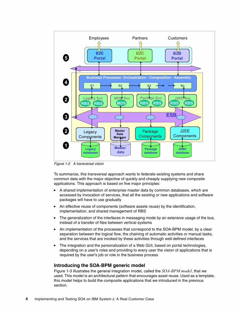
Figure 1-2 A transversal vision
To summarize, this transversal approach wants to federate existing systems and share common data with the major objective of quickly and cheaply supplying new composite applications. This approach is based on five major principles:
� A shared implementation of enterprise master data by common databases, which are accessed by invocation of services, that all the existing or new applications and software packages will have to use gradually
� An effective reuse of components (software assets reuse) by the identification, implementation, and shared management of RBS
� The generalization of the interfaces in messaging mode by an extensive usage of the bus, instead of a transfer of files between vertical systems
� An implementation of the processes that correspond to the SOA-BPM model, by a clear separation between the logical flow, the chaining of automatic activities or manual tasks, and the services that are invoked by these activities through well-defined interfaces
� The integration and the personalization of a Web GUI, based on portal technologies, depending on a user’s roles and providing to every user the vision of applications that is required by the user’s job or role in the business process
Introducing the SOA-BPM generic modelFigure 1-3 illustrates the general integration model, called the SOA-BPM model, that we used. This model is an architectural pattern that encourages asset reuse. Used as a template, this model helps to build the composite applications that we introduced in the previous section.
Employees CustomersPartners
Packagedatabase
Legacydatabases
JDBCdatabase
Legacy Components
PackageComponents
J2EE Components
ESB
Business Processes: Orchestration - Composition - Assembly
S1 S2 S3 Sn
B2E Portal
B2C Portal
B2B Portal
Legacy SvcRBSRBS
Package Svc J2EE SvcRBS RBS RBS RBS
1
4
3
5
Master data
MDM Svc
Master Data
Manager
MDS
2
2
4 Implementing and Testing SOA on IBM System z: A Real Customer Case
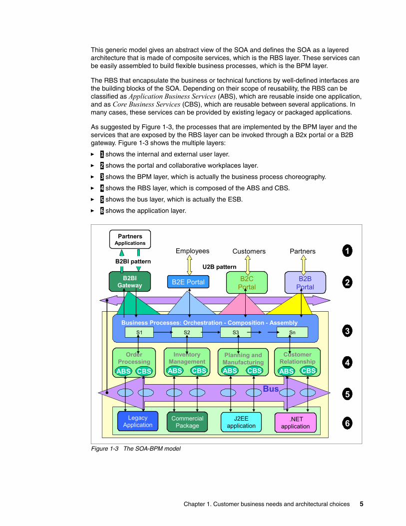
This generic model gives an abstract view of the SOA and defines the SOA as a layered architecture that is made of composite services, which is the RBS layer. These services can be easily assembled to build flexible business processes, which is the BPM layer.
The RBS that encapsulate the business or technical functions by well-defined interfaces are the building blocks of the SOA. Depending on their scope of reusability, the RBS can be classified as Application Business Services (ABS), which are reusable inside one application, and as Core Business Services (CBS), which are reusable between several applications. In many cases, these services can be provided by existing legacy or packaged applications.
As suggested by Figure 1-3, the processes that are implemented by the BPM layer and the services that are exposed by the RBS layer can be invoked through a B2x portal or a B2B gateway. Figure 1-3 shows the multiple layers:
� 1 shows the internal and external user layer.
� 2 shows the portal and collaborative workplaces layer.
� 3 shows the BPM layer, which is actually the business process choreography.
� 4 shows the RBS layer, which is composed of the ABS and CBS.
� 5 shows the bus layer, which is actually the ESB.
� 6 shows the application layer.
Figure 1-3 The SOA-BPM model
Business Processes: Orchestration - Composition - AssemblyS1 S2 S3 Sn
Employees Customers Partners
B2E Portal B2C Portal
B2B Portal
OrderProcessing
CBSABS
InventoryManagement
Planning andManufacturing
ABS CBS ABS
CustomerRelationshipABS CBSCBS
Legacy Application
CommercialPackage
J2EE application
.NETapplication
B2BIGateway
U2B pattern
Bus
Partners Applications
3
5
2
6
4
1B2BI pattern
Chapter 1. Customer business needs and architectural choices 5
The SOA-related technologies provide the encapsulation of new or existing components into RBS, by exporting Web Services Description Language (WSDL) interfaces. Thus they favor the reuse of software assets. These technologies will allow new services and interactions among these services to be built quickly.
These enterprise-scale components, which can be large-grained enterprise or business line components, are often built on heterogeneous technologies, such as legacy systems, commercial packages, J2EE, or Microsoft® .NET applications. They implement the functions invoked through the interface that is exported by the target business services. They are responsible for providing the requested functionality and maintaining their quality of service.
The processing flows between several related services can be fully automated by a BPM engine. The engine provides the orchestration and choreography mechanisms that expose them as a Web Services Business Process Execution Language (WS-BPEL) business process or a composite service.
In this architectural model, the BPM layer implements the target business processes as WS-BPEL models, combining automated activities and manual tasks. The automated activities invoke operations that are exported by RBS. These RBS can be implemented by legacy applications, commercial packages, and new J2EE or Microsoft .NET applications.
An ESB that is built on a “hub and spoke” infrastructure provides a common, powerful exchange mechanism between all the layers of the generic model. It allows all types of integration and supports the routing, the mediation, and the translation needs between the services, the components, and the BPM flows.
For each layer of the SOA-BPM model, the project architect must make design choices and make implementation decisions in accordance with this global vision.
The target architecture that is proposed for the project described in this book fully conforms to this model. It is a composite application that integrates multiple disparate and partially existing back-end systems by a new front-end system. The front-end system implements the process layer in Java and BPEL with the WebSphere Process Server, which is used as the integration platform.
1.1.2 The methodology aspects
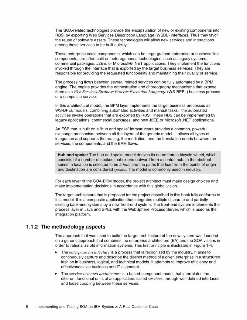
The approach that was used to build the target architecture of the new system was founded on a generic approach that combines the enterprise architecture (EA) and the SOA visions in order to rationalize old information systems. This first principle is illustrated in Figure 1-4.
� The enterprise architecture is a process that is recognized by the industry. It aims to continuously capture and describe the distinct method of a given enterprise in a structured fashion in business, logical, and technical models. It attempts to improve efficiency and effectiveness via business and IT alignment.
� The service-oriented architecture is a based-component model that interrelates the different functional units of an application, called services, through well-defined interfaces and loose coupling between these services.
Hub and spoke: The hub and spoke model derives its name from a bicycle wheel, which consists of a number of spokes that extend outward from a central hub. In the abstract sense, a location is selected to be a hub, and the paths that lead from the points of origin and destination are considered spokes. The model is commonly used in industry.
6 Implementing and Testing SOA on IBM System z: A Real Customer Case
By describing the interfaces with Extensible Markup Language (XML), the SOA allows services to interact with each other in a uniform and universal manner. They interact independently of hardware platforms, operating systems, and programming languages.
The SOA-related technologies provide the encapsulation of existing modules as WSDL exposed services, and therefore, favor the reuse of enterprise software assets.
Figure 1-4 Combining the EA and SOA visions
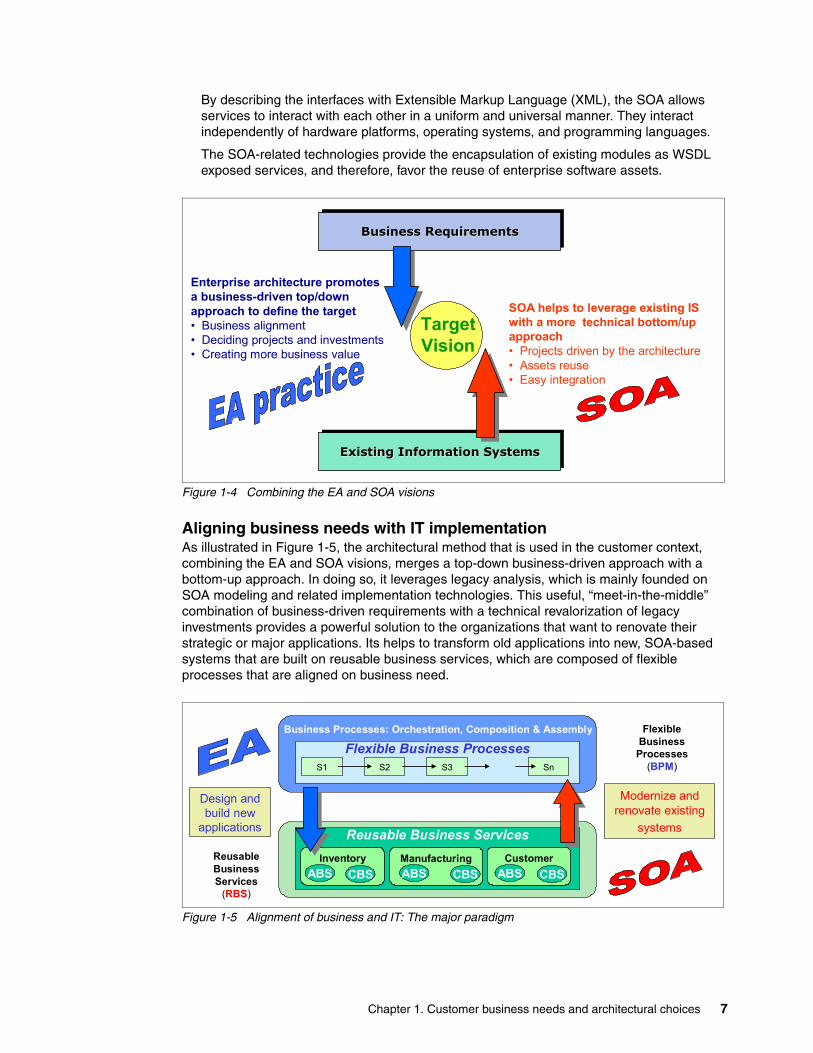
Aligning business needs with IT implementationAs illustrated in Figure 1-5, the architectural method that is used in the customer context, combining the EA and SOA visions, merges a top-down business-driven approach with a bottom-up approach. In doing so, it leverages legacy analysis, which is mainly founded on SOA modeling and related implementation technologies. This useful, “meet-in-the-middle” combination of business-driven requirements with a technical revalorization of legacy investments provides a powerful solution to the organizations that want to renovate their strategic or major applications. Its helps to transform old applications into new, SOA-based systems that are built on reusable business services, which are composed of flexible processes that are aligned on business need.
Figure 1-5 Alignment of business and IT: The major paradigm
Business RequirementsBusiness RequirementsBusiness Requirements
Existing Information SystemsExisting Information SystemsExisting Information Systems
Enterprise architecture promotes a business-driven top/down approach to define the target• Business alignment• Deciding projects and investments • Creating more business value
SOA helps to leverage existing IS with a more technical bottom/up approach• Projects driven by the architecture• Assets reuse• Easy integration
Target Vision
Business Processes: Orchestration, Composition & Assembly FlexibleBusiness Processes
(BPM)
ReusableBusinessServices
(RBS)
Flexible Business ProcessesS1 S2 S3 Sn
Reusable Business ServicesInventory Manufacturing
CBSABS CBSABSCustomer
CBSABS
Modernize andrenovate existing
systems
Design and build new
applications
Chapter 1. Customer business needs and architectural choices 7
Mainly founded on the SOA-BPM model and its related technical solutions (modeling methodology, implementation technologies, and development tools), this method is useful for:
� Designing and building new applications� Modernizing and renovating existing systems� Identifying, building, and exposing RBS
It aims to bridge the gap between the business vision and the IT implementation. In that objective, it associates the process vision of business analysts and the implementation view of IT architects and integration specialists.
SOA-BPM modeling and services mapping The method is well adapted to build a target architecture that conforms to the SOA-BPM model. In this architectural model, the BPM layer implements the target business processes as WS-BPEL models. The WS-BPEL models invoke operations that are exported by the RBS that can be provided by legacy applications, commercial packages, or new J2EE or Microsoft.NET applications.
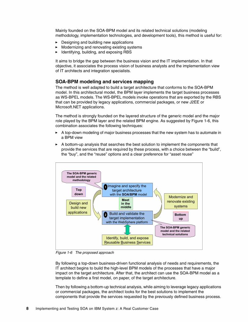
The method is strongly founded on the layered structure of the generic model and the major role played by the BPM layer and the related BPM engine. As suggested by Figure 1-6, this combination associates the following techniques:
� A top-down modeling of major business processes that the new system has to automate in a BPM view
� A bottom-up analysis that searches the best solution to implement the components that provide the services that are required by these process, with a choice between the “build”, the “buy”, and the “reuse” options and a clear preference for “asset reuse”
Figure 1-6 The proposed approach
By following a top-down business-driven functional analysis of needs and requirements, the IT architect begins to build the high-level BPM models of the processes that have a major impact on the target architecture. After that, the architect can use the SOA-BPM model as a template to define a first model, on paper, of the target architecture.
Then by following a bottom-up technical analysis, while aiming to leverage legacy applications or commercial packages, the architect looks for the best solutions to implement the components that provide the services requested by the previously defined business process.
Build and validate the target implementation
with the WebSphere platform
Imagine and specify the target architecture
with the SOA/BPM model
Identify, build, and exposeReusable Business Services
Design and build new
applications
The SOA-BPM generic model and the related
methodology
The SOA-BPM generic model and the related
technical solutions
Modernize andrenovate existing
systems
Top down
Bottom up
Meet in the middle
1
2
8 Implementing and Testing SOA on IBM System z: A Real Customer Case
To instrument each major component or subsystem of the target architecture, the architect can choose between the “build”, the “buy”, or the “reuse” options.
As illustrated in this document, the “build” option (Java components under WebSphere or WebSphere Process Server) and the “reuse” option (Cobol or Enterprise Generation Language (EGL) modules under IMS or CICS) solutions are mainly founded on SOA modeling and related implementation technologies. The “buy” option requires an efficient integration platform to transform the functions that are provided by ISV commercial packages into services that are invoked by well-defined WSDL interfaces.
As shown in Figure 1-6, the two major steps can be summarized as follows:
1. Imagine and specify the target architecture with the SOA-BPM generic model.
a. Model the main functional domains and the target business processes.
b. Define the high-level BPM model of the major business processes.
c. Build the targeted architectural model and detail its implementation in the two or three main solutions that are selected for study.
d. Specify the implementation of the major processes in the target architecture.
2. Build and validate the target implementation with the WebSphere platform.
a. Choose and refine two or three technical implementations of the proposed architecture (in terms of subsystems and partitions).
b. Specify the mock-ups to be realized in order to validate the target vision, which includes the definition of:
i. The requirements covered by the mock-upsii. The additional components shared between the mock-upsiii. The implementation of the main processes (in terms of BPEL, Service Component
Architecture (SCA), Enterprise JavaBean (EJB™), Direct Access Object (DAO), ESB and database, and so on
c. Design and implement these mock-ups:
i. Implement the technologies and the tools to use.ii. Experiment with the iterative development and the reusable components approach.
d. Execute intensive testing with these mock-ups.
This architectural approach, which is already used with success to build the target architecture of several large integration projects, is in conformity with the major concept of the Service Oriented Modeling and Architecture (SOMA) methodology of IBM. To learn more about SOMA, refer to the following Web address:
http://www-128.ibm.com/developerworks/library/ws-soa-design1/
The IBM Service Oriented Modeling and Architecture methodologyThe Service Oriented Modeling and Architecture methodology is an IBM methodology that helps a company to implement an SOA that supports its key business goals. It is founded on patterns and guidelines that aim to create loosely-coupled and business-aligned services. SOMA combines a top-down, business-driven service identification coupled with a bottom-up analysis of existing assets as legacy applications or ISV packages.
High-level business process functions are usually modeled as large-grained services. Smaller-grained services, which are aggregated to compose the high-level services, are often built from existing functionality. Adapters and wrappers help to extract the desired functions from the legacy applications or commercial packages such as SAP or Siebel solutions.
Chapter 1. Customer business needs and architectural choices 9
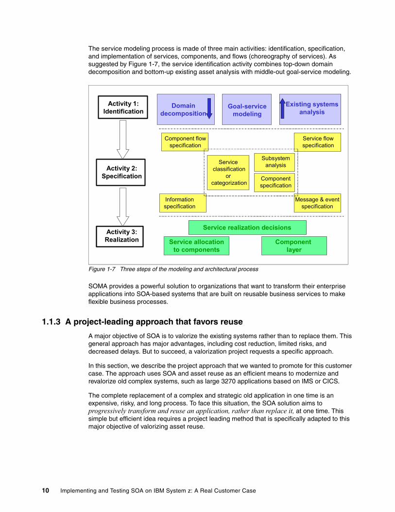
The service modeling process is made of three main activities: identification, specification, and implementation of services, components, and flows (choreography of services). As suggested by Figure 1-7, the service identification activity combines top-down domain decomposition and bottom-up existing asset analysis with middle-out goal-service modeling.
Figure 1-7 Three steps of the modeling and architectural process
SOMA provides a powerful solution to organizations that want to transform their enterprise applications into SOA-based systems that are built on reusable business services to make flexible business processes.
1.1.3 A project-leading approach that favors reuse
A major objective of SOA is to valorize the existing systems rather than to replace them. This general approach has major advantages, including cost reduction, limited risks, and decreased delays. But to succeed, a valorization project requests a specific approach.
In this section, we describe the project approach that we wanted to promote for this customer case. The approach uses SOA and asset reuse as an efficient means to modernize and revalorize old complex systems, such as large 3270 applications based on IMS or CICS.
The complete replacement of a complex and strategic old application in one time is an expensive, risky, and long process. To face this situation, the SOA solution aims to progressively transform and reuse an application, rather than replace it, at one time. This simple but efficient idea requires a project leading method that is specifically adapted to this major objective of valorizing asset reuse.
Domaindecomposition
Existing systemsanalysis
Service realization decisions
Goal-servicemodeling
Service allocationto components
Component layer
Component flowspecification
Service flowspecification
Message & eventspecification
Informationspecification
Service classification
or categorization
Componentspecification
SubsystemanalysisActivity 2:
Specification
Activity 1:Identification
Activity 3:Realization
10 Implementing and Testing SOA on IBM System z: A Real Customer Case
This approach entails the following major concepts:
� Break the global project into several subprojects of reasonable size (8 to 12 months), with each one bringing value to business and the first one building the foundations of the future system.
� Imagine and build a target architecture that addresses the business needs and allows a long and smooth cohabitation between the old system and the new one.
� Validate the target architecture and the migration process by realizing a prototype that includes the major building blocks of the future system. Each component has limited functionality to be compatible with the objectives and budget of a preliminary study.
� When compatible with the business needs, reuse the existing modules, after transformation, if required, rather than developing new components.
This approach, which aims to valorize the existing system by efficient asset reuse, is founded on the following principles:
� Architecture is the key to success.� Begin with a mock-up (prototype).� Progressively enrich the prototype.� Reuse rather than build.� Allow new and old components to work together.� Strongly secure the migration.� Break a global realization into several subprojects.
We explain each of these principles in the sections that follow. Then we conclude with the following items:
� The main benefits for renovation or renewal projects� Prerequisites of the technical platform and the architectural method
Architecture is the key of successThe building of a good architecture is an important condition to succeed with an integration project that aims to replace a large, complex, and strategic system. SOA technologies and a SOMA-based architectural method are the powerful tools to build an efficient architecture.
It is important is to begin the architectural work as soon as possible. At the beginning of the project, the functional needs are usually not well-known. Often the project leader thinks it is impossible to work on the target architecture at this time. However, it is the right time to make the first architectural decisions. Based on high-level business needs and a global analysis of the existing system, the first architectural model must be built soon. During preliminary study, this initial model is refined. Then at the end of this phase, the paper target architecture is the first valuable deliverable. After that, the technical validation phase of this architecture has the main objective to transform the vision from paper into a strong operational solution.
Defining the first architectural model has the following main advantages:
� All the analysis and specification work done by a business analyst is included in this architectural framework. The result of this work is really reusable in the following stages of the project.
� The initial architectural vision is largely improved with the implication of the business analysts.
� The bottom analysis of the existing system to discover existing assets that are usable to implement some components of the target architecture is strongly simplified if this one is already partially defined. The discovery of valuable assets can impact the target architecture.
Chapter 1. Customer business needs and architectural choices 11
The architectural model at this stage is the result of the two complementary visions, the business analyst vision and the integration specialist vision. The resulting “meet-in-the-middle” architectural model allows all people who are involved in the project to work with a common framework and to deliver a really usable production.
Begin with a mock-up (prototype)
Generally, a mock-up or prototype aims to validate the main architectural, functional, and technical decisions. If the mock-up is carefully designed, it can be easily extended and you can have multiple versions of the mock-up. Each step adds components to the previous version in order to become the foundation of the future system. Little by little, this mock-up is upgraded with real application code to become the first deliverable of the project.
The mock-up or prototype implements all the architectural elements of the target architecture but has limited functions. It voluntarily simplifies the processes, the business rules, and the complexity of the code that is required to implement the services.
To achieve the benefit of reusing existing assets, the target architecture often integrates legacy systems, such as IMS or CICS and WebSphere. In such as case, the mock-up or prototype must combine IMS or CICS assets, the old transactions and related DL/I or DB2 databases, WebSphere resources, new Java components, and new DB2 databases.
The coding of the mock-up or prototype can start as soon as its specifications are written. As soon as the development is ended, the mock-up or prototype is integrated with the old system according to the principles that are defined for the target solution. The tests and the integration with the acceptance system can start immediately after the development phase.
The interest of this approach is to validate the target architecture early in the process. It also reduces the duration of the specification, the development, and the tests. We can also imply the users earlier than in a classic method, which allows them to validate better the specifications.
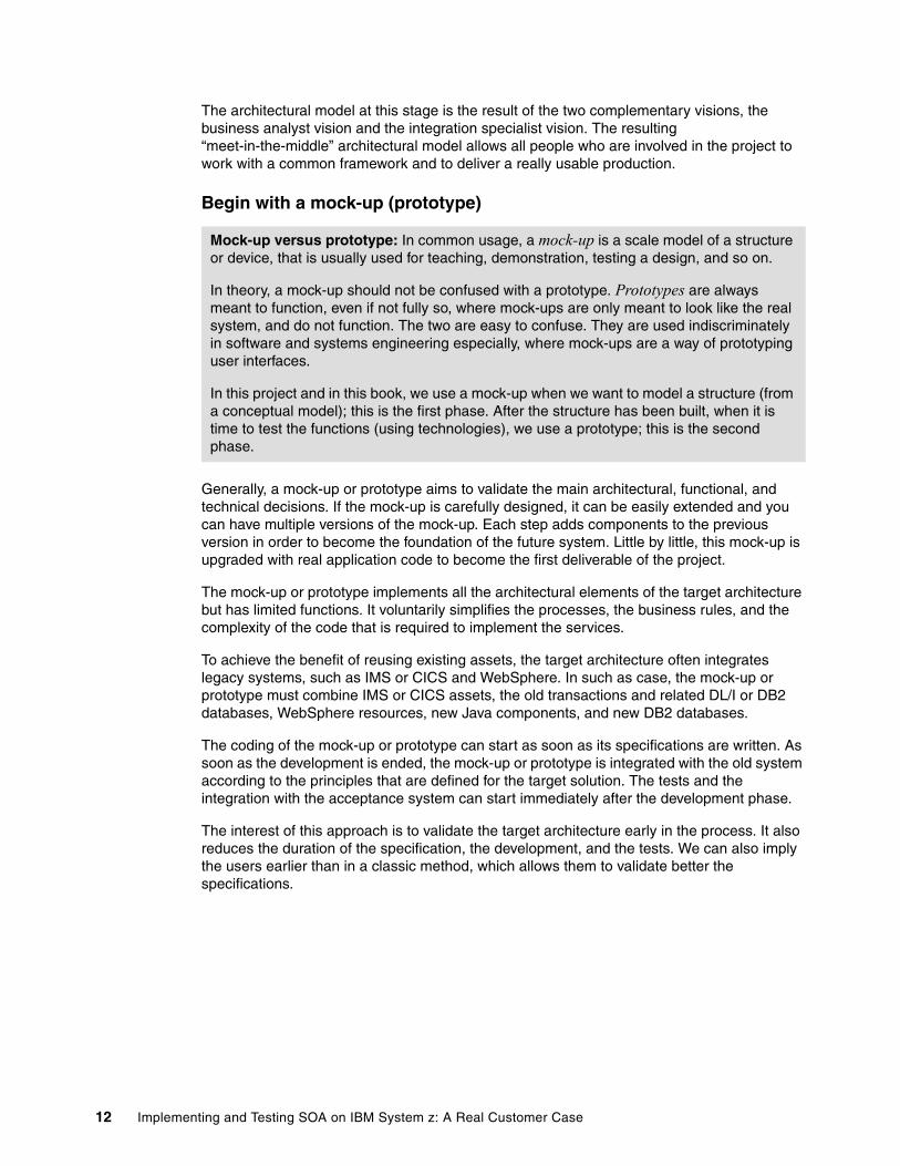
Mock-up versus prototype: In common usage, a mock-up is a scale model of a structure or device, that is usually used for teaching, demonstration, testing a design, and so on.
In theory, a mock-up should not be confused with a prototype. Prototypes are always meant to function, even if not fully so, where mock-ups are only meant to look like the real system, and do not function. The two are easy to confuse. They are used indiscriminately in software and systems engineering especially, where mock-ups are a way of prototyping user interfaces.
In this project and in this book, we use a mock-up when we want to model a structure (from a conceptual model); this is the first phase. After the structure has been built, when it is time to test the functions (using technologies), we use a prototype; this is the second phase.
12 Implementing and Testing SOA on IBM System z: A Real Customer Case
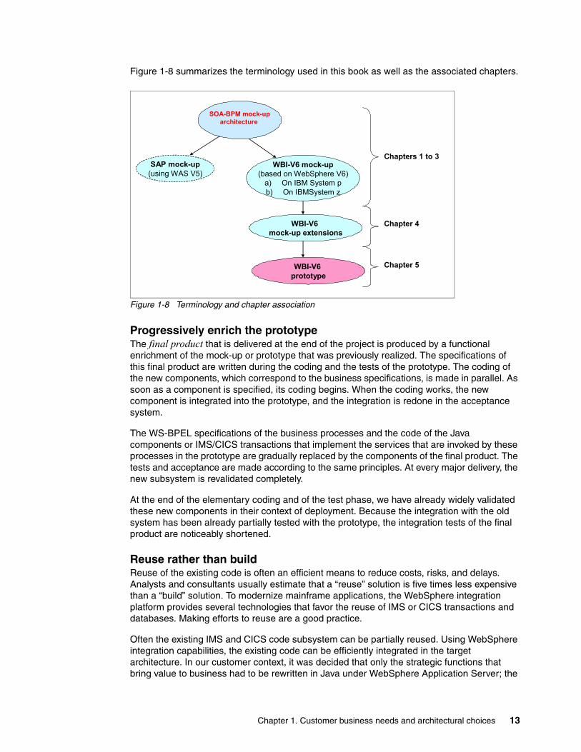
Figure 1-8 summarizes the terminology used in this book as well as the associated chapters.
Figure 1-8 Terminology and chapter association
Progressively enrich the prototypeThe final product that is delivered at the end of the project is produced by a functional enrichment of the mock-up or prototype that was previously realized. The specifications of this final product are written during the coding and the tests of the prototype. The coding of the new components, which correspond to the business specifications, is made in parallel. As soon as a component is specified, its coding begins. When the coding works, the new component is integrated into the prototype, and the integration is redone in the acceptance system.
The WS-BPEL specifications of the business processes and the code of the Java components or IMS/CICS transactions that implement the services that are invoked by these processes in the prototype are gradually replaced by the components of the final product. The tests and acceptance are made according to the same principles. At every major delivery, the new subsystem is revalidated completely.
At the end of the elementary coding and of the test phase, we have already widely validated these new components in their context of deployment. Because the integration with the old system has been already partially tested with the prototype, the integration tests of the final product are noticeably shortened.
Reuse rather than buildReuse of the existing code is often an efficient means to reduce costs, risks, and delays. Analysts and consultants usually estimate that a “reuse” solution is five times less expensive than a “build” solution. To modernize mainframe applications, the WebSphere integration platform provides several technologies that favor the reuse of IMS or CICS transactions and databases. Making efforts to reuse are a good practice.
Often the existing IMS and CICS code subsystem can be partially reused. Using WebSphere integration capabilities, the existing code can be efficiently integrated in the target architecture. In our customer context, it was decided that only the strategic functions that bring value to business had to be rewritten in Java under WebSphere Application Server; the
SOA-BPM mock-uparchitecture
WBI-V6 mock-up(based on WebSphere V6)
a) On IBM System pb) On IBMSystem z
SAP mock-up(using WAS V5)
WBI-V6 mock-up extensions
WBI-V6 prototype
Chapters 1 to 3
Chapter 5
Chapter 4
Chapter 1. Customer business needs and architectural choices 13
other functions could remain under IMS or CICS. If necessary, some DL/I databases would be migrated to DB2.
Commercial packages, such as SAP solutions, can also be used to implement some functions. For example, a business process can invoke services implemented by standard or customized SAP modules through the Business Application Programming Interfaces (BAPI®) or Intermediate Documents (IDOC) interfaces and one or several mediation tasks provided by the ESB.
Allow new and old components to work togetherTo allow secure migration, the new components under WebSphere must support a long cohabitation with the old components under IMS and CICS. The new and old databases must then be synchronized.
The target architecture is based on efficient integration between WebSphere and IMS or CICS, combining a partial rewriting (in Java) with the reuse of Cobol or EGL components. The value of EGL is detailed in 5.1.1, “Enterprise Generation Language overview” on page 128.
� The strategic functions are rewritten in Java under WebSphere. They access new DB2 databases.
� The other functions may be reused as Existing Business Services (EBS) after an encapsulation of the existing code that may require a transformation of the former code into EGL as explained in 5.1.1, “Enterprise Generation Language overview” on page 128.
� The former DL/I databases are also reused to allow the former programs to work without modifications.
� A non-intrusive replication mechanism provides synchronization between the former DL/I databases and the new ones under DB2.
The generic solution is an iterative and progressive renovation that:
� Applies the SOA-BPM model and uses the integration platform in order to:
– Rewrite the strategic functions in Java to bring values to business
– Transform the other functions as EBS, or convert them into EGL, to limit the costs and risks of a complete replacement
� Starts the project by building the architectural foundation of the future system based on:
– A strong integration between IMS and WebSphere
– A synchronized replication between DL/I and DB2 through the ESB
Enterprise Generation Language: EGL is a fourth-generation computer programming language. Its origins trace back to the IBM Cross Systems Product 4GL. It subsequently became VisualAge® Generator and evolved into its current status as a strategic business development language. IBM created EGL to help procedural programmers, particularly those with RPG and COBOL experience, learn the concepts and practices of object-oriented programming more easily. EGL programming tools are available as a set of commercial plug-ins to the Eclipse-based IBM Rational® products, such as Rational Application Developer and WebSphere Developer for System z. EGL generates the user’s choice of either Java and COBOL executable code. Therefore, EGL programs can run on practically all platforms and can address high performance business computing.
14 Implementing and Testing SOA on IBM System z: A Real Customer Case
Strongly secure the migrationOne fundamental principle is to allow a progressive migration, based on a smooth cohabitation between the new and the former system during a potential long period. The users can submit transactions to the former system or in the new system. At first, the new system can be seen as an additional channel with a Web interface for accessing the former channel, on a system that generally uses 3270 screens.
For example, existing 3270 screen interfaces that are used by external users can be converted into a Web interface to be included in a B2B portal in the first steps of the project. The 3270 screens interfaces, which are used only by internal agents, may be transformed later into Web pages. External user interfaces are often less numerous than internal user interfaces. This operation may be expensive if the application itself is made of many screens. Also, the interfaces with the other information systems are still in charge of the former system.
Except for the initial load of the additional databases newly created, there is no need for mechanisms to load master data. The existing programs can be reused to load and update databases.
A smooth cohabitation between the old system and the new system allows iterative development and progressive deployment. It also secures strongly the migration process.
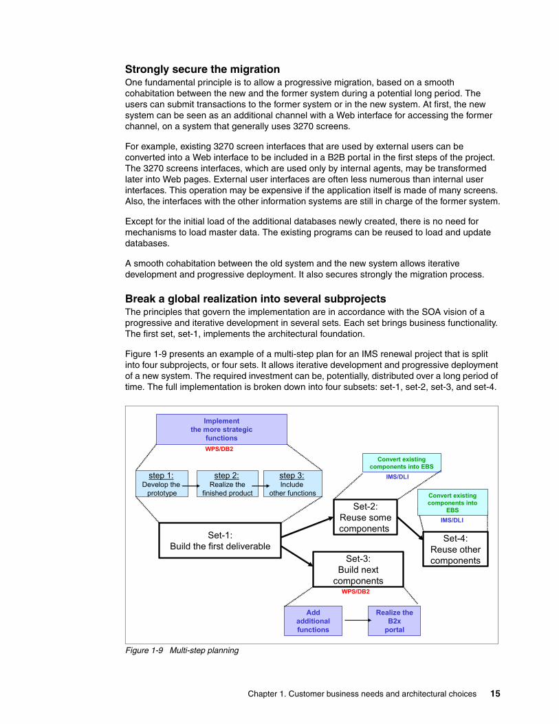
Break a global realization into several subprojectsThe principles that govern the implementation are in accordance with the SOA vision of a progressive and iterative development in several sets. Each set brings business functionality. The first set, set-1, implements the architectural foundation.
Figure 1-9 presents an example of a multi-step plan for an IMS renewal project that is split into four subprojects, or four sets. It allows iterative development and progressive deployment of a new system. The required investment can be, potentially, distributed over a long period of time. The full implementation is broken down into four subsets: set-1, set-2, set-3, and set-4.
Figure 1-9 Multi-step planning
Realize the B2x
portal
Convert existing components into EBS
Set-1:Build the first deliverable
Set-2:Reuse somecomponents
Set-3:Build next
components
Set-4:Reuse othercomponents
step 1:Develop the
prototype
step 2:Realize the
finished product
step 3:Include
other functions
Addadditionalfunctions
IMS/DLI
IMS/DLI
WPS/DB2
Implement the more strategic
functions
Convert existing components into
EBS
WPS/DB2
IMS/DLI
Chapter 1. Customer business needs and architectural choices 15
The multistep plan follows this approach:
1. Set-1 implements the most strategic functions and offers to the external users an ergonomic Web interface. It implements the most strategic functions, which immediately brings a strong business value. It implements the architectural foundation that is required for the whole project. In set-1, the first step builds the prototype as an extension of a mock-up that is developed during the preliminary study. Then sets 2 and 3 enrich this prototype to produce the first deliverable of the project.
2. Set-2 aims to reuse an IMS component and fully integrates this component in a new business process. The transformation of the 3270 screens into a Web interface is an option that needs to be evaluated.
3. Set-3 implements new databases or extends the existing ones. It also realizes the modifications of the processes or the services that are required to implement the functional extensions that are requested by the business. The modification of the processes is made at the BPEL level or by new business rules. The modification of the services called by these processes requires modification or rewriting of some components, for example WebSphere or Java services, or IMS or EGL transactions.
4. Set-4 aims to reuse another IMS component and integrate it in a new process by making the required adaptations.
Set-2 and set-3 can be realized independently.
Main benefits for renovation or renewal projectsFor the projects that aim to modernize an old mainframe application, this approach offers the following main advantages:
� It allows iterative development and progressive development in a multi-step project.
� It authorizes a long and smooth cohabitation that secures the migration process.
� Compared with a scenario of a complete replacement, it reduces costs, delays, and risks by reusing existing assets and productivity improvement. It delivers a product that is usable in production after step 1.
Prerequisites of the technical platform and architectural methodTo lead this approach, the following major elements are required:
� A strong integration platform (WebSphere Version 6 with the BPM, ESB, and portal extensions) that includes efficient technologies and simplifies the reuse of existing software assets
� A proven method of architecture (based on the main SOMA concepts) that combines a top-down, business-driven vision with a bottom-up analysis that aims to valorize existing systems
16 Implementing and Testing SOA on IBM System z: A Real Customer Case
1.1.4 The customer environment and business context
The “WBI V6” mock-up that is described in this book was developed during the preliminary study of a large integration project in the automotive industry. The customer is a major worldwide OEM, that had already chosen the WebSphere solutions for all its new information system (IS) projects that require a J2EE application server or an integration platform. The objective of this project was to modernize an old strategic application that was written in the early 1990s in order to automate the distribution of spare parts through a network of dealers.
From a high-level view, the old application and the new system must have the same requirements. They need to automate three major business processes and are both made of the three same subsystems:
1. The management of the incoming orders (for spare parts) received from dealers
The subsystem that automates this process is known as OM for Orders Management.
2. The management of the production in the warehouses that deliver parts to the ordering dealers
This subsystem is known as WM for Warehouse Management or WMS, which is usually the acronym for commercial packages that automate this need.
3. The management of the supply chain that aims to optimize the global level of inventory and to pilot the re-supply process for missing parts from their suppliers
This is known as SCM for Supply Chain Management.
This strategic application has to process about 300,000 orders every day in a first step and more than 500,000 in the future. It requires a high quality of service in terms of:
� High availability� Subsecond response times� Scalability
The high-level business functions that are provided by the old and new system are the same. They are provided by the three subsystems that were previously introduced: OM, WMS, and SCM. Figure 1-10 illustrates the three subsystems, the major functions they provide, and the main flow of business events exchanged between the subsystems. The subsystems are explained in detail in the sections that follow.
Chapter 1. Customer business needs and architectural choices 17

Figure 1-10 The major business functions
Orders Management The OM subsystem supports the following actions:
� Receives, controls, and registers incoming orders� Allows dealers to follow-up on the status of their orders in real time � Monitors the deliveries and notifies the dealers when their parts packages have been
delivered
The spare part orders that are received from dealers are controlled by the OM subsystem against the parts database. After processing the business rules and checking the level of inventory, the valid orders are registered in the orders database and are then transmitted to the WMS subsystem.
The main objective of the SOA-BPM mock-up is to automate the major business process known as Create_Order. As shown in Figure 1-11, the OM subsystem entails three main functions:
1. Control and register new orders received from dealers
The orders can be received from a Dealer Management System (DMS) or typed into the Web portal. Then, the order needs to be validated and registered in the orders database. A reservation is made for these parts in the inventory database. After that, the valid orders are sent to the WMS subsystem.
1 – Control and register new orders receivedfrom dealers
3 – Deliver and invoice
2 – Track the progress of orders processing
1
Orders
OM
4 – Schedule and process orders
Packaging Loading DeliveryPicking
Execute operations
5 – Processreceptions
2WM (WMS)
Receptions
6 - Supply chain
Forecast the sales
Evaluate the needs
Activate the re-supply process
7 – Resupply and inventory management
IM
SCM 3
SCM (Package)
Orders Inventory
InvoicesDeliveries
Orders
DeliveriesOrders
ReceptionsShipping notices
Order delivery
OrdersReceptions
Shipping notices
Parts Dealers
Shippingnotice
Delivery
18 Implementing and Testing SOA on IBM System z: A Real Customer Case
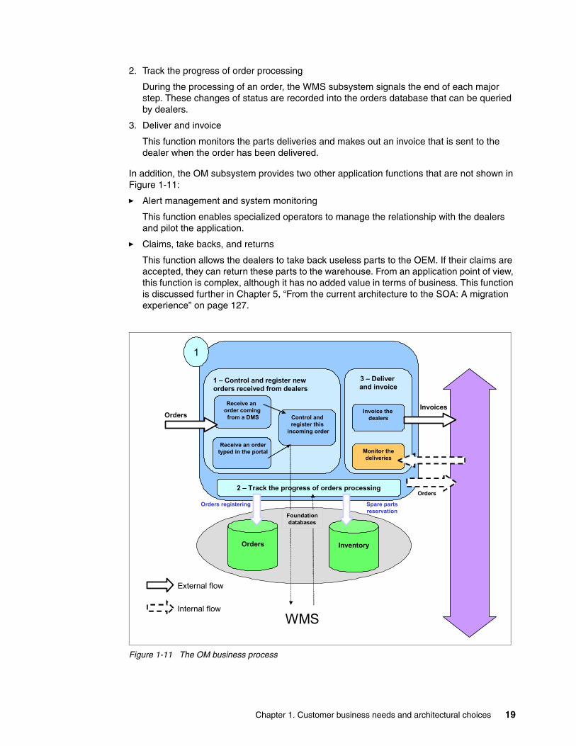
2. Track the progress of order processing
During the processing of an order, the WMS subsystem signals the end of each major step. These changes of status are recorded into the orders database that can be queried by dealers.
3. Deliver and invoice
This function monitors the parts deliveries and makes out an invoice that is sent to the dealer when the order has been delivered.
In addition, the OM subsystem provides two other application functions that are not shown in Figure 1-11:
� Alert management and system monitoring
This function enables specialized operators to manage the relationship with the dealers and pilot the application.
� Claims, take backs, and returns
This function allows the dealers to take back useless parts to the OEM. If their claims are accepted, they can return these parts to the warehouse. From an application point of view, this function is complex, although it has no added value in terms of business. This function is discussed further in Chapter 5, “From the current architecture to the SOA: A migration experience” on page 127.
Figure 1-11 The OM business process
1 – Control and register new orders received from dealers
Receive an order coming
from a DMS
Receive an order typed in the portal
Control andregister this
incoming order
3 – Deliver and invoice
Invoice the dealers
Monitor thedeliveries
2 – Track the progress of orders processing
1
Orders
Orders Inventory
Orders registering Spare partsreservation
Invoices
Orders
Foundationdatabases
WMSInternal flow
External flow
Chapter 1. Customer business needs and architectural choices 19
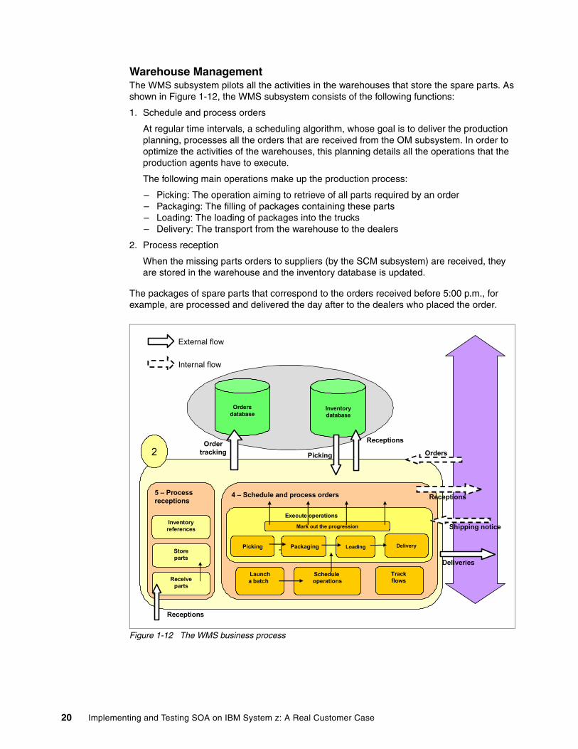
Warehouse ManagementThe WMS subsystem pilots all the activities in the warehouses that store the spare parts. As shown in Figure 1-12, the WMS subsystem consists of the following functions:
1. Schedule and process orders
At regular time intervals, a scheduling algorithm, whose goal is to deliver the production planning, processes all the orders that are received from the OM subsystem. In order to optimize the activities of the warehouses, this planning details all the operations that the production agents have to execute.
The following main operations make up the production process:
– Picking: The operation aiming to retrieve of all parts required by an order – Packaging: The filling of packages containing these parts– Loading: The loading of packages into the trucks – Delivery: The transport from the warehouse to the dealers
2. Process reception
When the missing parts orders to suppliers (by the SCM subsystem) are received, they are stored in the warehouse and the inventory database is updated.
The packages of spare parts that correspond to the orders received before 5:00 p.m., for example, are processed and delivered the day after to the dealers who placed the order.
Figure 1-12 The WMS business process
4 – Schedule and process orders
Schedule operations
Trackflows
Packaging Loading DeliveryPicking
Launcha batch
Mark out the progression
5 – Processreceptions
Inventoryreferences
Receiveparts
Storeparts
2
Receptions
Ordersdatabase
Inventorydatabase
Ordertracking
Receptions
Picking
Shipping notice
Deliveries
Orders
Receptions
Internal flow
External flow
Execute operations
20 Implementing and Testing SOA on IBM System z: A Real Customer Case
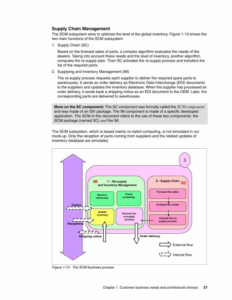
Supply Chain ManagementThe SCM subsystem aims to optimize the level of the global inventory. Figure 1-13 shows the two main functions of the SCM subsystem:
1. Supply Chain (SC)
Based on the forecast sales of parts, a complex algorithm evaluates the needs of the dealers. Taking into account these needs and the level of inventory, another algorithm computes the re-supply plan. Then SC activates the re-supply process and transfers the list of the required parts.
2. Supplying and Inventory Management (IM)
The re-supply process requests each supplier to deliver the required spare parts to warehouses. It sends an order delivery as Electronic Data Interchange (EDI) documents to the suppliers and updates the inventory database. When the supplier has processed an order delivery, it sends back a shipping notice as an EDI document to the OEM. Later, the corresponding parts are delivered to warehouses.
The SCM subsystem, which is based mainly on batch computing, is not simulated in our mock-up. Only the reception of parts coming from suppliers and the related updates of inventory database are simulated.
Figure 1-13 The SCM business process
More on the SC component: The SC component was formally called the SCM component and was made of an ISV package. The IM component is made of a specific developed application. The SCM in this document refers to the use of these two components: the SCM package (named SC) and the IM.
6 - Supply Chain
Forecast the sales
Evaluate the needs
Activate the re-supply process
7 – Re-supply and Inventory Management
Execute the re-supply process
Checkavailability
Reservereferences
Updateinventory
3
Order delivery
Receptions
Orders
Shipping notice
IM SC
Internal flow
External flow
Chapter 1. Customer business needs and architectural choices 21
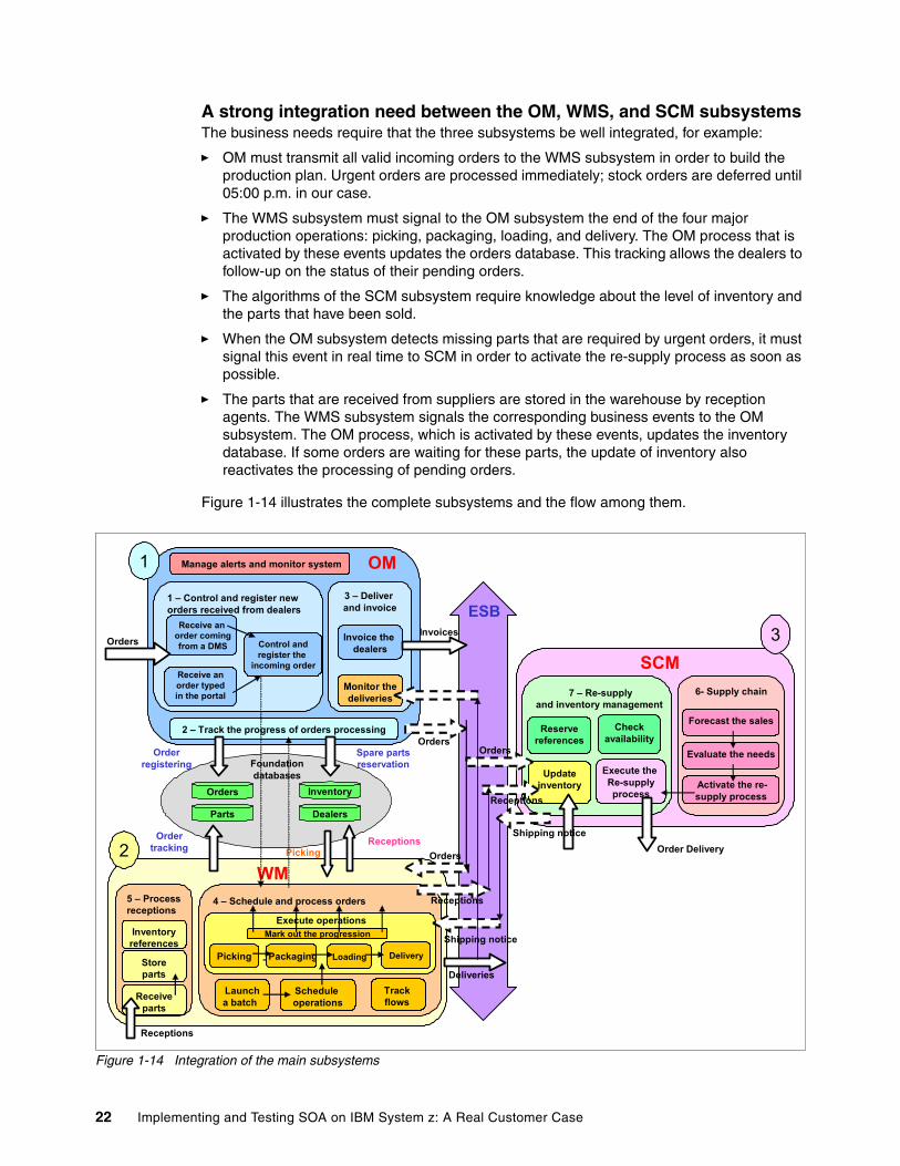
A strong integration need between the OM, WMS, and SCM subsystemsThe business needs require that the three subsystems be well integrated, for example:
� OM must transmit all valid incoming orders to the WMS subsystem in order to build the production plan. Urgent orders are processed immediately; stock orders are deferred until 05:00 p.m. in our case.
� The WMS subsystem must signal to the OM subsystem the end of the four major production operations: picking, packaging, loading, and delivery. The OM process that is activated by these events updates the orders database. This tracking allows the dealers to follow-up on the status of their pending orders.
� The algorithms of the SCM subsystem require knowledge about the level of inventory and the parts that have been sold.
� When the OM subsystem detects missing parts that are required by urgent orders, it must signal this event in real time to SCM in order to activate the re-supply process as soon as possible.
� The parts that are received from suppliers are stored in the warehouse by reception agents. The WMS subsystem signals the corresponding business events to the OM subsystem. The OM process, which is activated by these events, updates the inventory database. If some orders are waiting for these parts, the update of inventory also reactivates the processing of pending orders.
Figure 1-14 illustrates the complete subsystems and the flow among them.
Figure 1-14 Integration of the main subsystems
1 – Control and register new orders received from dealers
Receive an order comingfrom a DMS
Receive an order typedin the portal
Control andregister the
incoming order
3 – Deliver and invoice
Invoice the dealers
Monitor thedeliveries
2 – Track the progress of orders processing
Manage alerts and monitor system1
Orders
OM
4 – Schedule and process orders
Schedule operations
Trackflows
Packaging Loading DeliveryPicking
Execute operations
Launcha batch
Mark out the progression
5 – Processreceptions
Inventoryreferences
Receiveparts
Storeparts
2WM
Receptions
6- Supply chain
Forecast the sales
Evaluate the needs
Activate the re-supply process
7 – Re-supplyand inventory management
Execute the Re-supplyprocess
Checkavailability
Reservereferences
Updateinventory
SCM3
Shipping noticeOrder Delivery
Order registering
Ordertracking
Spare partsreservation
ReceptionsPicking
Shipping notice
Deliveries
Orders
Receptions
Receptions
OrdersOrders
Foundationdatabases
ESB
Orders Inventory
Parts Dealers
Invoices
22 Implementing and Testing SOA on IBM System z: A Real Customer Case
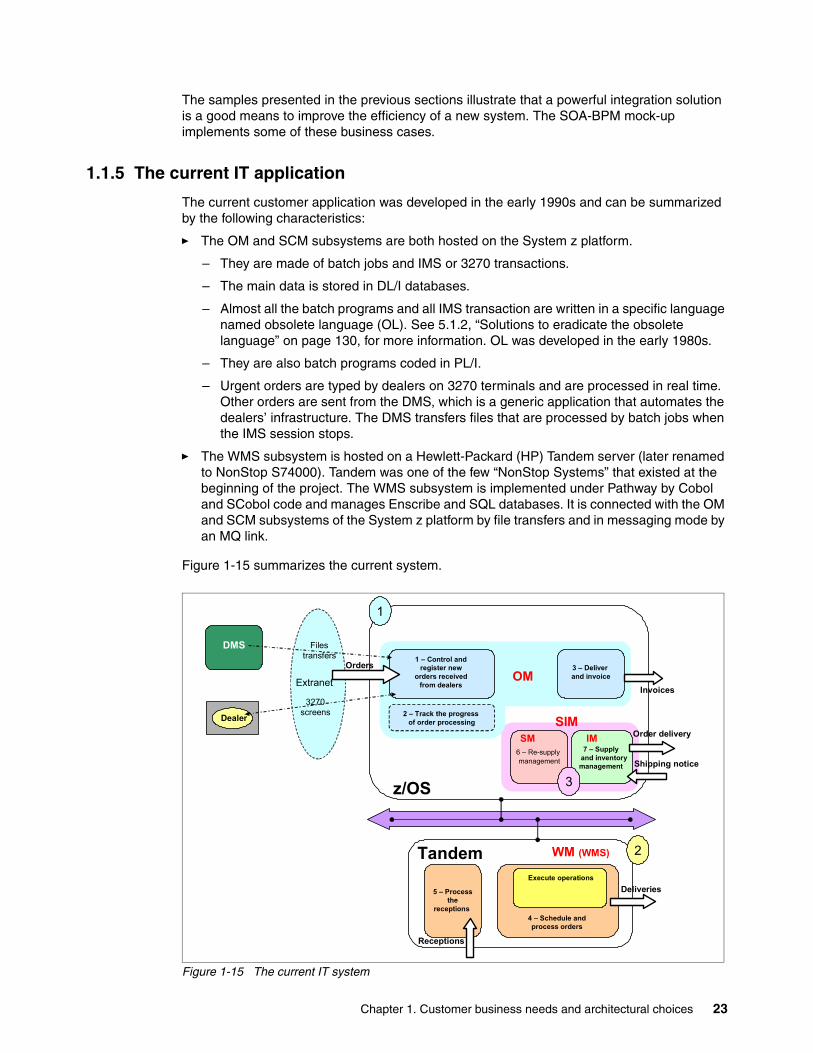
The samples presented in the previous sections illustrate that a powerful integration solution is a good means to improve the efficiency of a new system. The SOA-BPM mock-up implements some of these business cases.
1.1.5 The current IT application
The current customer application was developed in the early 1990s and can be summarized by the following characteristics:
� The OM and SCM subsystems are both hosted on the System z platform.
– They are made of batch jobs and IMS or 3270 transactions.
– The main data is stored in DL/I databases.
– Almost all the batch programs and all IMS transaction are written in a specific language named obsolete language (OL). See 5.1.2, “Solutions to eradicate the obsolete language” on page 130, for more information. OL was developed in the early 1980s.
– They are also batch programs coded in PL/I.
– Urgent orders are typed by dealers on 3270 terminals and are processed in real time. Other orders are sent from the DMS, which is a generic application that automates the dealers’ infrastructure. The DMS transfers files that are processed by batch jobs when the IMS session stops.
� The WMS subsystem is hosted on a Hewlett-Packard (HP) Tandem server (later renamed to NonStop S74000). Tandem was one of the few “NonStop Systems” that existed at the beginning of the project. The WMS subsystem is implemented under Pathway by Cobol and SCobol code and manages Enscribe and SQL databases. It is connected with the OM and SCM subsystems of the System z platform by file transfers and in messaging mode by an MQ link.
Figure 1-15 summarizes the current system.
Figure 1-15 The current IT system
1 – Control and register new
orders received from dealers
OM3 – Deliver and invoice
4 – Schedule and process orders
Execute operations
5 – Processthe
receptions
WM (WMS)
6 – Re-supplymanagement
SIMDealer
DMS
2 – Track the progress of order processing
Extranet
1
Deliveries
Receptions
Shipping notice
Orders
Invoices
7 – Supplyand inventory management
IM
2
Order delivery
Tandem
z/OS
SM
3
3270screens
Filestransfers
Chapter 1. Customer business needs and architectural choices 23
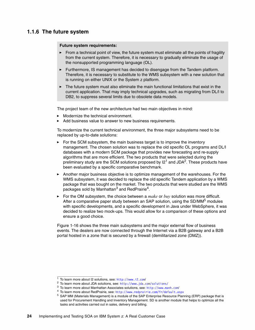
1.1.6 The future system
The project team of the new architecture had two main objectives in mind:
� Modernize the technical environment.� Add business value to answer to new business requirements.
To modernize the current technical environment, the three major subsystems need to be replaced by up-to-date solutions:
� For the SCM subsystem, the main business target is to improve the inventory management. The chosen solution was to replace the old specific OL programs and DL/I databases with a modern SCM package that provides new forecasting and re-supply algorithms that are more efficient. The two products that were selected during the preliminary study are the SCM solutions proposed by I21 and JDA2. These products have been evaluated by a specific comparative benchmark.
� Another major business objective is to optimize management of the warehouses. For the WMS subsystem, it was decided to replace the old specific Tandem application by a WMS package that was bought on the market. The two products that were studied are the WMS packages sold by Manhattan3 and RedPrairie4.
� For the OM subsystem, the choice between a make or buy solution was more difficult. After a comparative paper study between an SAP solution, using the SD/MM5 modules with specific developments, and a specific development in Java under WebSphere, it was decided to realize two mock-ups. This would allow for a comparison of these options and ensure a good choice.
Figure 1-16 shows the three main subsystems and the major external flow of business events. The dealers are now connected through the Internet via a B2B gateway and a B2B portal hosted in a zone that is secured by a firewall (demilitarized zone (DMZ)).
Future system requirements:
� From a technical point of view, the future system must eliminate all the points of fragility from the current system. Therefore, it is necessary to gradually eliminate the usage of the nonsupported programming language (OL).
� Furthermore, IS management has decided to disengage from the Tandem platform. Therefore, it is necessary to substitute to the WMS subsystem with a new solution that is running on either UNIX or the System z platform.
� The future system must also eliminate the main functional limitations that exist in the current application. That may imply technical upgrades, such as migrating from DL/I to DB2, to suppress several limits due to obsolete data models.
1 To learn more about I2 solutions, see: http://www.i2.com/2 To learn more about JDA solutions, see: http://www.jda.com/solutions/3 To learn more about Manhattan Associates solutions, see: http://www.manh.com/4 To learn more about RedPrairie, see: http://www.redprairie.com/fr/default.aspx5 SAP MM (Materials Management) is a module of the SAP Enterprise Resource Planning (ERP) package that is
used for Procurement Handling and Inventory Management. SD is another module that helps to optimize all the tasks and activities carried out in sales, delivery and billing.
24 Implementing and Testing SOA on IBM System z: A Real Customer Case
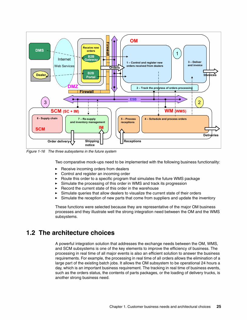
Figure 1-16 The three subsystems in the future system
Two comparative mock-ups need to be implemented with the following business functionality:
� Receive incoming orders from dealers� Control and register an incoming order� Route this order to a specific program that simulates the future WMS package� Simulate the processing of this order in WMS and track its progression� Record the current state of this order in the warehouse� Simulate queries that allow dealers to visualize the current state of their orders� Simulate the reception of new parts that come from suppliers and update the inventory
These functions were selected because they are representative of the major OM business processes and they illustrate well the strong integration need between the OM and the WMS subsystems.
1.2 The architecture choices
A powerful integration solution that addresses the exchange needs between the OM, WMS, and SCM subsystems is one of the key elements to improve the efficiency of business. The processing in real time of all major events is also an efficient solution to answer the business requirements. For example, the processing in real time of all orders allows the elimination of a large part of the existing batch jobs. It allows the OM subsystem to be operational 24 hours a day, which is an important business requirement. The tracking in real time of business events, such as the orders status, the contents of parts packages, or the loading of delivery trucks, is another strong business need.
Receive neworders
B2BGateway
B2BPortal
1 – Control and register new orders received from dealers
OM
3 – Deliver and invoice
4 – Schedule and process orders 5 – Processreceptions
2
WM (WMS)
6 - Supply chain
SCM
7 – Re-supply and inventory management
IM
SCM (SC + IM)
Dealer
DMS
2 – Track the progress of orders processing
1
3
Deliveries
ReceptionsShippingnotice
Order delivery
Firewall
Firewall
Orders
Invoices
ESB
Internet
Web Services
DMZ
Chapter 1. Customer business needs and architectural choices 25
SOA and related technologies, such as BPM, ESB, and portal, offer an efficient means to align the business needs with the corresponding IT solutions.
� An ESB allows the transmission in real time of all major business events between the OM, WMS, and SCM subsystems.
� An efficient BPM solution allows the orchestration of real-time business processes that are initiated by external events, such as the arrival of an urgent order, the reception of parts coming from dealers, or a missing part condition into the processing of an urgent order.
Some of these business processes require that agents execute manual tasks when a special condition occurs. For example, in a Create_Order process, a business rule can stop the automatic processing of a valid order. In that case, a manual task that is executed by a technical agent must decide if the order is either rejected, with a notification sent to the dealer, or accepted, with a restart of the standard processing.
A missing part condition that is detected by the WebSphere Process Server can stop the standard Create_Order process of an incoming order. As soon as the corresponding part is received from a supplier, the related business event, which is sent by the WMS subsystem to WebSphere Process Server, reactivates the processing of the pending order.
� A B2x (B2B, B2C, or B2E) portal that personalizes the view of the business processes depending on the role of people (dealer, technical agent, manager, and so on) increases the value added by the IT solution.
� A B2B gateway allows the replacement of file transfers by asynchronous messages that are based on Web services. The DMS that equips each dealer can directly activate the Create_Order process onto the OEM system by sending an XML message to the gateway.
The architects who were involved in this project were also in charge of evaluating the SOA solutions and the corresponding WebSphere Version 6 technologies, including the BPM solutions, the ESB, the B2x portal, and the B2B gateway. Taking into account the major choices that influence the architecture and the main business needs, this project was chosen to test how the SOA target vision would be implemented.
Two mock-ups were required to choose between an integration solution, based on SAP, and a full WebSphere solution, to validate the major SOA architectural concepts and the efficiency of the related WebSphere integration platform technical solution. Therefore, it was decided that the architecture of the two mock-ups must conform to the generic SOA-BPM model.
This model is an architectural pattern that helps to build SOA composite applications and favors reuse of software assets. It gives an abstract view of the SOA and defines the SOA as a layered architecture that is made of composite services that can be easily assembled to build flexible business processes.
The following items are the main architectural orientations:
� A target vision conform to the SOA-BPM model � A design based on major SOMA concepts� An iterative development and progressive deployment� A first experimentation of BPM solutions
These items are explained from a conceptual point of view in the sections that follow. How the existing products and solutions can implement these concepts is explained in 1.3, “From the architecture to the prototype” on page 33.
As described in the following chapters, the WBI V6 mock-up has proven that these major orientations were good and this test was considered as a true success by the customer.
26 Implementing and Testing SOA on IBM System z: A Real Customer Case
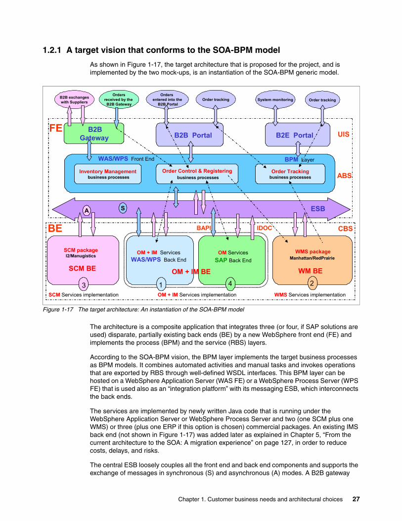
1.2.1 A target vision that conforms to the SOA-BPM model
As shown in Figure 1-17, the target architecture that is proposed for the project, and is implemented by the two mock-ups, is an instantiation of the SOA-BPM generic model.
Figure 1-17 The target architecture: An instantiation of the SOA-BPM model
The architecture is a composite application that integrates three (or four, if SAP solutions are used) disparate, partially existing back ends (BE) by a new WebSphere front end (FE) and implements the process (BPM) and the service (RBS) layers.
According to the SOA-BPM vision, the BPM layer implements the target business processes as BPM models. It combines automated activities and manual tasks and invokes operations that are exported by RBS through well-defined WSDL interfaces. This BPM layer can be hosted on a WebSphere Application Server (WAS FE) or a WebSphere Process Server (WPS FE) that is used also as an “integration platform” with its messaging ESB, which interconnects the back ends.
The services are implemented by newly written Java code that is running under the WebSphere Application Server or WebSphere Process Server and two (one SCM plus one WMS) or three (plus one ERP if this option is chosen) commercial packages. An existing IMS back end (not shown in Figure 1-17) was added later as explained in Chapter 5, “From the current architecture to the SOA: A migration experience” on page 127, in order to reduce costs, delays, and risks.
The central ESB loosely couples all the front end and back end components and supports the exchange of messages in synchronous (S) and asynchronous (A) modes. A B2B gateway
B2BGateway
ESB
FE
BE CBS
WAS/WPS Front End
SCM packageI2/Manugistics
WMS packageManhattan/RedPrairie
ABS
A
B2B Portal
WM BE
2
SCM BE
3
S
UISB2E Portal
BPM Layer
Order Control & Registeringbusiness processes
Order Trackingbusiness processes
Inventory Managementbusiness processes
OM + IM ServicesWAS/WPS Back End
OM + IM BE
OM ServicesSAP Back End
Order trackingSystem monitoringOrders
received by the B2B Gateway
Orders entered into the
B2B PortalOrder tracking
OM + IM Services implementation
B2B exchangeswith Suppliers
WMS Services implementationSCM Services implementation
1 4
IDOCBAPI
Chapter 1. Customer business needs and architectural choices 27
and a B2B portal allow the commercial partners (dealers and suppliers) to access to the processes and services that are exposed by the WebSphere front end.
Incoming orders are received from the DMS through the B2B gateway or are manually typed by dealers using an ergonomic Web interface hosted by the B2B portal. This B2B portal provides the User Interface Service (UIS), which is implemented as a portlet, that allows dealers to access the order tracking process.
The B2B messaging exchanges with the suppliers (sending of order deliveries and receiving shipping notices) flow through the B2B gateway. A B2E portal allows specialized OEM operators that support the dealers to monitor the application and to follow-up on the status of the incoming orders.
By adopting this model, the project can quickly build a new, flexible system that automates the major business processes and strongly reuses existing assets.
1.2.2 An iterative development and progressive deployment
The first estimations of a preliminary study showed that a complete replacement of the former system at one time was an expensive, risky, and long process. The main reason is that the former system is a complex and strategic application.
To address this situation, a general SOA recommendation was proposed to progressively transform and reuse the system, rather than to replace it. This simple but efficient idea requires a project leading method that is specifically adapted to this objective.
This method entails the following main concepts:
� Break the project into several subprojects of reasonable size, with a priority of building the architectural foundation of the new system.
� Build a target architecture that allows a long cohabitation between the old and new systems, simplifying the migration and supporting a progressive deployment.
� Validate this architecture and the related migration process as soon as possible by realizing a mock-up (or prototype).
� Try to reuse the existing modules rather than develop new components.
As explained in 5.2, “Target architecture of the new system” on page 135, the OM target architecture reuses several existing IMS/OL modules and DL/I databases in order to reduce the costs, delays, and risks. After the OL code is translated into EGL, it can be reused (without risk) rather than writing new Java code.
The WBI V6 mock-up has been designed with respect to these principles. Its main objective is to validate the WebSphere Process Server or Java part of the target architecture. It is made of new code that is written in Java, using DB2 databases and running in the WebSphere Process Server infrastructure. Chapter 3, “Implementation of the WebSphere Process Server V6 mock-up” on page 85, describes this SOA mock-up.
The initial mock-up can be easily extended to build a prototype that aims to validate the target architecture of the new system. In order to demonstrate how to reuse the existing code, this prototype adds the IMS, EGL, or DL/I environment to the WebSphere Process Server or Java foundation of the SOA mock-up. It includes an ESB (the WebSphere ESB) that is required to
IMS/OL modules: IMS/OL modules are written with the “obsolete language” nonstandard language as explained in 5.1, “A generic solution to eradicate the obsolete language” on page 128.
28 Implementing and Testing SOA on IBM System z: A Real Customer Case
efficiently integrate WebSphere Process Server and DB2 with IMS or DL/I (through the IMS or JCA connectors and a DL/I or DB2 replication mechanism). This ESB also supports the integration code that will integrate the future WMS and SCM packages with the OM subsystem. Chapter 5, “From the current architecture to the SOA: A migration experience” on page 127, details the realization of this prototype that also builds the foundation of the future system whose prototype is the first deliverable.
1.2.3 SOA-BPM vision of the business processes
The two mock-ups implement the architecture that is built from the method that is described in 1.1.2, “The methodology aspects” on page 6. We started with a BPM modeling of the few business processes that have a strong influence on this architecture. Then, we used the SOA-BPM generic model as a template to define a first architectural vision of the future system. This first draft implemented these two or three processes as required by the SOA-BPM model. Its BPM layer orchestrates automatic activities and manual tasks and invokes services provided by the RBS layer. This top-down business-driven modeling is completed by a bottom-up analysis to discover the best solutions to implement these services, with generally a choice of the buy, make, or reuse options.
Figure 1-18 illustrates the functional domains that are covered by the project. It shows the SOA-BPM vision of the three main business processes that aim to:
1. Process the orders coming from the dealers (1)
2. Receive the parts sent by the suppliers and update the inventory database (2)
3. Supply the missing references (3)
The re-supply process that is optimized by the SCM package is out of the scope of the two mock-ups and may be implemented in a further step.
Chapter 1. Customer business needs and architectural choices 29
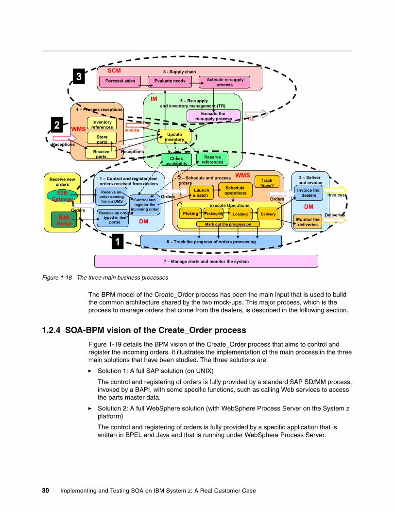
Figure 1-18 The three main business processes
The BPM model of the Create_Order process has been the main input that is used to build the common architecture shared by the two mock-ups. This major process, which is the process to manage orders that come from the dealers, is described in the following section.
1.2.4 SOA-BPM vision of the Create_Order process
Figure 1-19 details the BPM vision of the Create_Order process that aims to control and register the incoming orders. It illustrates the implementation of the main process in the three main solutions that have been studied. The three solutions are:
� Solution 1: A full SAP solution (on UNIX)
The control and registering of orders is fully provided by a standard SAP SD/MM process, invoked by a BAPI, with some specific functions, such as calling Web services to access the parts master data.
� Solution 2: A full WebSphere solution (with WebSphere Process Server on the System z platform)
The control and registering of orders is fully provided by a specific application that is written in BPEL and Java and that is running under WebSphere Process Server.
Receive neworders
5 – Re-supply and inventory management (TR)
6 – Track the progress of orders processing
7 – Manage alerts and monitor the system
2 – Schedule and processorders
3 – Deliver and invoice
1 – Control and register new orders received from dealers
B2BGateway
B2BPortal
8 - Supply chain
Forecast sales Evaluate needs
SCM
Updateinventory
IM
OLExecute the
re-supply process
Orders
Checkavailability
Reservereferences
Receive an order comingfrom a DMS
Receive an order typed in the
portal
Control andregister the
incoming order
Invoice the dealers
Schedule operations
Trackflows?
4 – Process receptions
Inventoryreferences
Receiveparts
Storeparts
Orders
Receptions
Invoices
Invoice
Activate re-supplyprocess
Monitor thedeliveries
DeliveriesPackaging Loading DeliveryPicking
Execute Operations
Launch a batch
Mark out the progression
Receptions
Orders
WMS
DM
DM
WMS
1
2
3
30 Implementing and Testing SOA on IBM System z: A Real Customer Case
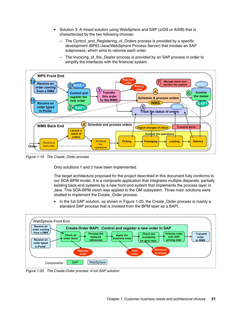
� Solution 3: A mixed solution using WebSphere and SAP (z/OS or AIX®) that is characterized by the two following choices:
– The Control_and_Registering_of_Orders process is provided by a specific development (BPEL/Java/WebSphere Process Server) that invokes an SAP subprocess, which aims to valorize each order.
– The Invoicing_of_the_Dealer process is provided by an SAP process in order to simplify the interfaces with the financial system.
Figure 1-19 The Create_Order process
Only solutions 1 and 2 have been implemented.
The target architecture proposed for the project described in this document fully conforms to our SOA-BPM model. It is a composite application that integrates multiple disparate, partially existing back-end systems by a new front-end system that implements the process layer in Java. This SOA-BPM vision was applied to the OM subsystem. Three main solutions were studied to implement the Create_Order process.
� In the full SAP solution, as shown in Figure 1-20, the Create_Order process is mainly a standard SAP process that is invoked from the BPM layer as a BAPI.
Figure 1-20 The Create-Order process: A full SAP solution
Schedule & process orders
Receive anew order
Launch a batch oforders
Schedulethe
operations
Schedule and process orders
Order
Receive anorder comingfrom a DMS
Rejectedorder
Waitingorder
Execute the operations
Packaging Loading DeliveryPicking
WMS Back End
Track the status of orders
Transferthis order
to the WMS
WPS Front End
Transmit alerts
Receive anorder typed
in Portal
Manage alerts andmonitor the system
1a
1b2
3 4 6
7
5
WAS?
SAP?WMS
WAS?
WASSAP?
Signal changes of status4
2Control andregister the new order
Invoicethe dealer
Check allorder items
Rejectedorder
WebSphere Front End
Process thereplaced
references
Apply thebusiness rules
Check theavailability
for each item
Valorize order with SAP
pricing data
Transmitorder
to WMS
Create-Order BAPI: Control and register a new order in SAPReceive anorder comingfrom a DMS
Receive anorder typed
in PortalHeldorder
Referenceto supply
SAP WebSphereComponents:
Chapter 1. Customer business needs and architectural choices 31
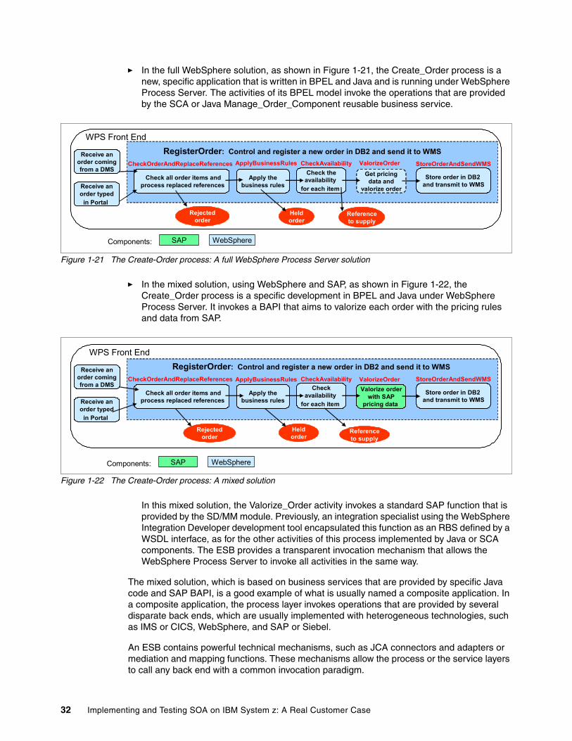
� In the full WebSphere solution, as shown in Figure 1-21, the Create_Order process is a new, specific application that is written in BPEL and Java and is running under WebSphere Process Server. The activities of its BPEL model invoke the operations that are provided by the SCA or Java Manage_Order_Component reusable business service.
Figure 1-21 The Create-Order process: A full WebSphere Process Server solution
� In the mixed solution, using WebSphere and SAP, as shown in Figure 1-22, the Create_Order process is a specific development in BPEL and Java under WebSphere Process Server. It invokes a BAPI that aims to valorize each order with the pricing rules and data from SAP.
Figure 1-22 The Create-Order process: A mixed solution
In this mixed solution, the Valorize_Order activity invokes a standard SAP function that is provided by the SD/MM module. Previously, an integration specialist using the WebSphere Integration Developer development tool encapsulated this function as an RBS defined by a WSDL interface, as for the other activities of this process implemented by Java or SCA components. The ESB provides a transparent invocation mechanism that allows the WebSphere Process Server to invoke all activities in the same way.
The mixed solution, which is based on business services that are provided by specific Java code and SAP BAPI, is a good example of what is usually named a composite application. In a composite application, the process layer invokes operations that are provided by several disparate back ends, which are usually implemented with heterogeneous technologies, such as IMS or CICS, WebSphere, and SAP or Siebel.
An ESB contains powerful technical mechanisms, such as JCA connectors and adapters or mediation and mapping functions. These mechanisms allow the process or the service layers to call any back end with a common invocation paradigm.
Rejectedorder
WPS Front End
Apply thebusiness rules
Check theavailability
for each item
Get pricingdata and
valorize order
RegisterOrder: Control and register a new order in DB2 and send it to WMS
Check all order items andprocess replaced references
Store order in DB2 and transmit to WMS
CheckOrderAndReplaceReferences ApplyBusinessRules CheckAvailability StoreOrderAndSendWMS
Heldorder
ValorizeOrderReceive an
order comingfrom a DMS
Receive anorder typed
in Portal
Referenceto supply
SAP WebSphereComponents:
Rejectedorder
WPS Front End
CheckOrderAndReplaceReferences ApplyBusinessRules CheckAvailability StoreOrderAndSendWMS
Heldorder
ValorizeOrderReceive an
order comingfrom a DMS
Receive anorder typed
in Portal
RegisterOrder: Control and register a new order in DB2 and send it to WMS
Apply thebusiness rules
Checkavailability
for each item
Check all order items andprocess replaced references
Store order in DB2 and transmit to WMS
Valorize order with SAP
pricing data
Referenceto supply
SAP WebSphereComponents:
32 Implementing and Testing SOA on IBM System z: A Real Customer Case
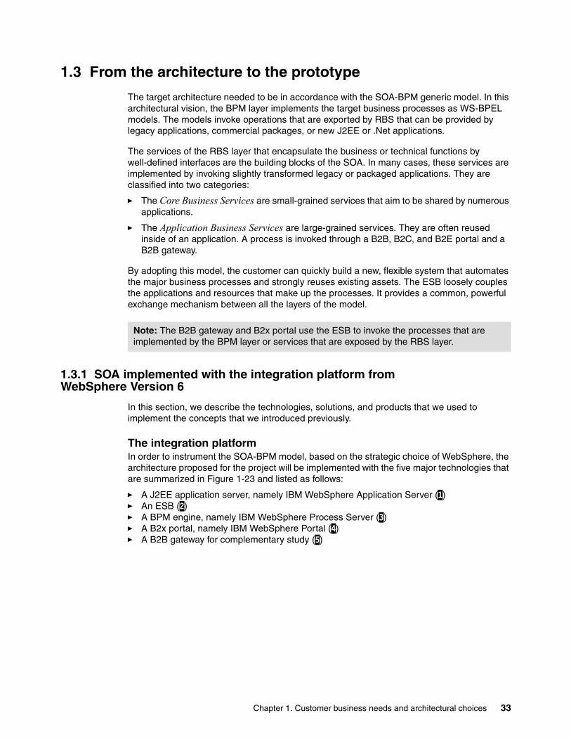
1.3 From the architecture to the prototype
The target architecture needed to be in accordance with the SOA-BPM generic model. In this architectural vision, the BPM layer implements the target business processes as WS-BPEL models. The models invoke operations that are exported by RBS that can be provided by legacy applications, commercial packages, or new J2EE or .Net applications.
The services of the RBS layer that encapsulate the business or technical functions by well-defined interfaces are the building blocks of the SOA. In many cases, these services are implemented by invoking slightly transformed legacy or packaged applications. They are classified into two categories:
� The Core Business Services are small-grained services that aim to be shared by numerous applications.
� The Application Business Services are large-grained services. They are often reused inside of an application. A process is invoked through a B2B, B2C, and B2E portal and a B2B gateway.
By adopting this model, the customer can quickly build a new, flexible system that automates the major business processes and strongly reuses existing assets. The ESB loosely couples the applications and resources that make up the processes. It provides a common, powerful exchange mechanism between all the layers of the model.
1.3.1 SOA implemented with the integration platform from WebSphere Version 6
In this section, we describe the technologies, solutions, and products that we used to implement the concepts that we introduced previously.
The integration platformIn order to instrument the SOA-BPM model, based on the strategic choice of WebSphere, the architecture proposed for the project will be implemented with the five major technologies that are summarized in Figure 1-23 and listed as follows:
� A J2EE application server, namely IBM WebSphere Application Server (1)� An ESB (2)� A BPM engine, namely IBM WebSphere Process Server (3)� A B2x portal, namely IBM WebSphere Portal (4)� A B2B gateway for complementary study (5)
Note: The B2B gateway and B2x portal use the ESB to invoke the processes that are implemented by the BPM layer or services that are exposed by the RBS layer.
Chapter 1. Customer business needs and architectural choices 33
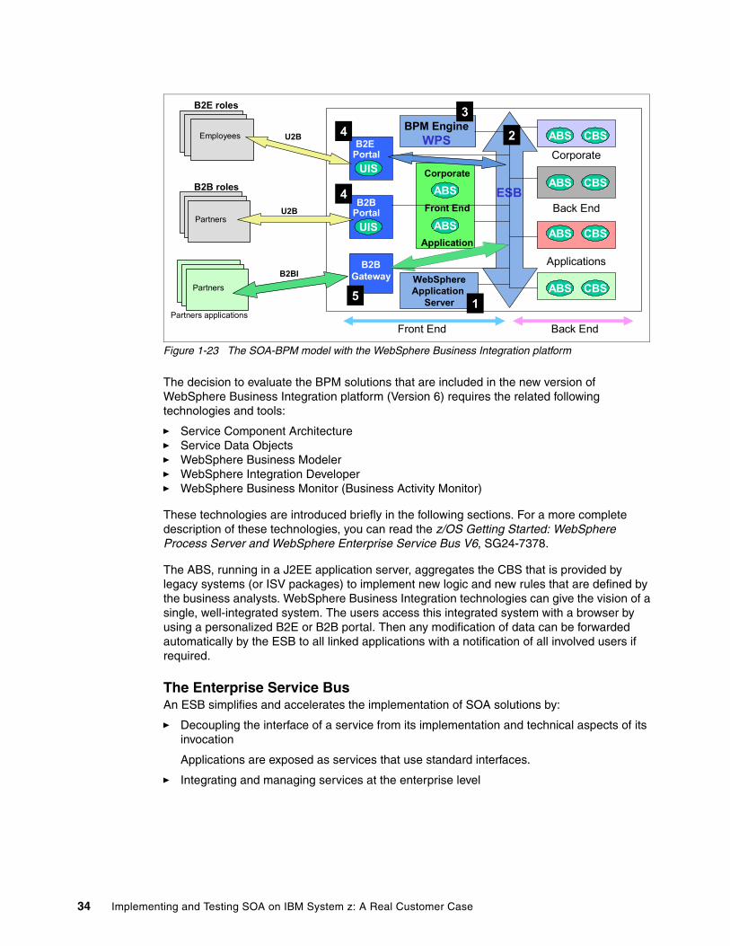
Figure 1-23 The SOA-BPM model with the WebSphere Business Integration platform
The decision to evaluate the BPM solutions that are included in the new version of WebSphere Business Integration platform (Version 6) requires the related following technologies and tools:
� Service Component Architecture� Service Data Objects� WebSphere Business Modeler� WebSphere Integration Developer� WebSphere Business Monitor (Business Activity Monitor)
These technologies are introduced briefly in the following sections. For a more complete description of these technologies, you can read the z/OS Getting Started: WebSphere Process Server and WebSphere Enterprise Service Bus V6, SG24-7378.
The ABS, running in a J2EE application server, aggregates the CBS that is provided by legacy systems (or ISV packages) to implement new logic and new rules that are defined by the business analysts. WebSphere Business Integration technologies can give the vision of a single, well-integrated system. The users access this integrated system with a browser by using a personalized B2E or B2B portal. Then any modification of data can be forwarded automatically by the ESB to all linked applications with a notification of all involved users if required.
The Enterprise Service BusAn ESB simplifies and accelerates the implementation of SOA solutions by:
� Decoupling the interface of a service from its implementation and technical aspects of its invocation
Applications are exposed as services that use standard interfaces.
� Integrating and managing services at the enterprise level
Corporate
Back End
Applications
Employees
B2E roles
B2E Portal
Partners
B2B Portal
Partners
B2B Gateway
B2B roles
Partners applications
Corporate
Front End
Application
ESB
U2B
U2B
B2BI
BPM EngineWPS
ABS
ABS
CBS
CBS
CBS
CBSWebSphereApplication
Server
Front End Back End
UIS
UIS
ABS
ABS
ABS
ABS1
2
34
4
5
34 Implementing and Testing SOA on IBM System z: A Real Customer Case
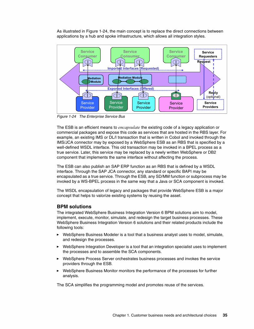
As illustrated in Figure 1-24, the main concept is to replace the direct connections between applications by a hub and spoke infrastructure, which allows all integration styles.
Figure 1-24 The Enterprise Service Bus
The ESB is an efficient means to encapsulate the existing code of a legacy application or commercial packages and expose this code as services that are hosted in the RBS layer. For example, an existing IMS or DL/I transaction that is written in Cobol and invoked through the IMS/JCA connector may by exposed by a WebSphere ESB as an RBS that is specified by a well-defined WSDL interface. This old transaction may be invoked in a BPEL process as a true service. Later, this service may be replaced by a newly written WebSphere or DB2 component that implements the same interface without affecting the process.
The ESB can also publish an SAP ERP function as an RBS that is defined by a WSDL interface. Through the SAP JCA connector, any standard or specific BAPI may be encapsulated as a true service. Through the ESB, any SD/MM function or subprocess may be invoked by a WS-BPEL process in the same way that a Java or SCA component is invoked.
The WSDL encapsulation of legacy and packages that provide WebSphere ESB is a major concept that helps to valorize existing systems by reusing the asset.
BPM solutionsThe integrated WebSphere Business Integration Version 6 BPM solutions aim to model, implement, execute, monitor, simulate, and redesign the target business processes. These WebSphere Business Integration Version 6 solutions and their related products include the following tools:
� WebSphere Business Modeler is a tool that a business analyst uses to model, simulate, and redesign the processes.
� WebSphere Integration Developer is a tool that an integration specialist uses to implement the processes and to assemble the SCA components.
� WebSphere Process Server orchestrates business processes and invokes the service providers through the ESB.
� WebSphere Business Monitor monitors the performance of the processes for further analysis.
The SCA simplifies the programming model and promotes reuse of the services.
ServiceConsumer
ServiceProvider
ServiceProvider
ServiceProvider
ServiceProvider
ServiceConsumer
ServiceConsumer
MediationModule
Mediation Module
I
I I II
I II
ServiceProviders
ServiceRequesters
Exported Interfaces (Offered)
Imported Interfaces (Requested)
Request
Reply(optional)
Chapter 1. Customer business needs and architectural choices 35
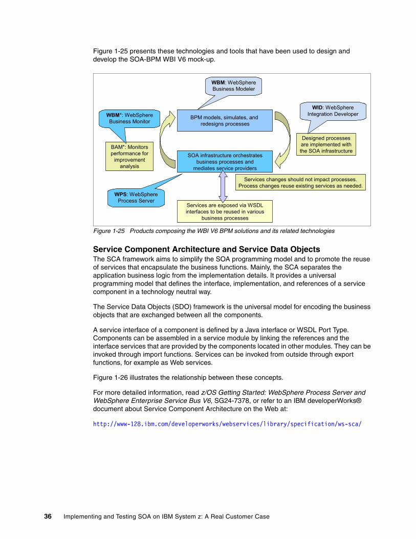
Figure 1-25 presents these technologies and tools that have been used to design and develop the SOA-BPM WBI V6 mock-up.
Figure 1-25 Products composing the WBI V6 BPM solutions and its related technologies
Service Component Architecture and Service Data ObjectsThe SCA framework aims to simplify the SOA programming model and to promote the reuse of services that encapsulate the business functions. Mainly, the SCA separates the application business logic from the implementation details. It provides a universal programming model that defines the interface, implementation, and references of a service component in a technology neutral way.
The Service Data Objects (SDO) framework is the universal model for encoding the business objects that are exchanged between all the components.
A service interface of a component is defined by a Java interface or WSDL Port Type. Components can be assembled in a service module by linking the references and the interface services that are provided by the components located in other modules. They can be invoked through import functions. Services can be invoked from outside through export functions, for example as Web services.
Figure 1-26 illustrates the relationship between these concepts.
For more detailed information, read z/OS Getting Started: WebSphere Process Server and WebSphere Enterprise Service Bus V6, SG24-7378, or refer to an IBM developerWorks® document about Service Component Architecture on the Web at:
http://www-128.ibm.com/developerworks/webservices/library/specification/ws-sca/
Services are exposed via WSDLinterfaces to be reused in various
business processes
SOA infrastructure orchestratesbusiness processes and
mediates service providers
BPM models, simulates, and redesigns processes
Services changes should not impact processes.Process changes reuse existing services as needed.
Designed processes are implemented with the SOA infrastructure
BAM*: Monitors performance for
improvementanalysis
WBM*: WebSphereBusiness Monitor
WPS: WebSphereProcess Server
WBM: WebSphereBusiness Modeler
WID: WebSphereIntegration Developer
36 Implementing and Testing SOA on IBM System z: A Real Customer Case
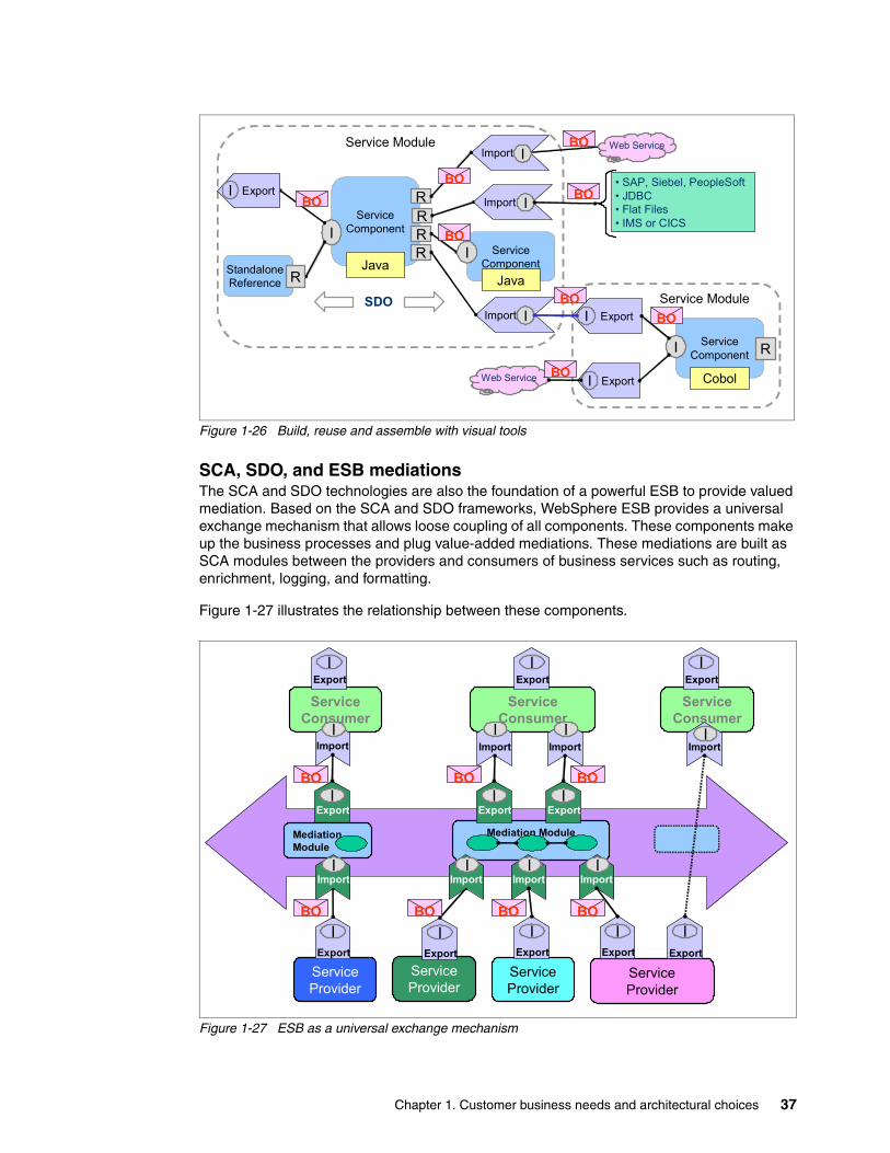
Figure 1-26 Build, reuse and assemble with visual tools
SCA, SDO, and ESB mediationsThe SCA and SDO technologies are also the foundation of a powerful ESB to provide valued mediation. Based on the SCA and SDO frameworks, WebSphere ESB provides a universal exchange mechanism that allows loose coupling of all components. These components make up the business processes and plug value-added mediations. These mediations are built as SCA modules between the providers and consumers of business services such as routing, enrichment, logging, and formatting.
Figure 1-27 illustrates the relationship between these components.
Figure 1-27 ESB as a universal exchange mechanism
Service Module
Service Module
ServiceComponentI
Java
RR
Export I
ServiceComponent
I
JavaStandalone Reference R
ServiceComponentI
Cobol
R
Export IImport
R
I
Export IWeb Service
• SAP, Siebel, PeopleSoft• JDBC• Flat Files• IMS or CICS
Import IR
Import I
SDO
BO
BO
BO
BO
BO
BO
BO
BO
Web Service
ServiceConsumer
ServiceProvider
ServiceProvider
ServiceProvider
ServiceProvider
IExport
IExport
IImport
ServiceConsumer
IExport
IImport
ServiceConsumer
IExport
IImport
IImport
MediationModule
Mediation Module
IImport
IImport
IExport
IExport
IExport
IExport
IExport
IExport
IExport
IImport
IImport
BO
BO BO BO
BO BOBO
Chapter 1. Customer business needs and architectural choices 37
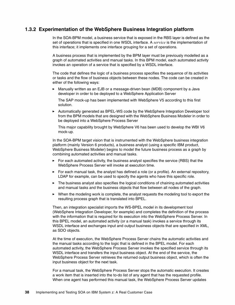
1.3.2 Experimentation of the WebSphere Business Integration platform
In the SOA-BPM model, a business service that is exposed in the RBS layer is defined as the set of operations that is specified in one WSDL interface. A service is the implementation of this interface; it implements one interface grouping for a set of operations.
A business process that is implemented by the BPM layer must be previously modelled as a graph of automated activities and manual tasks. In this BPM model, each automated activity invokes an operation of a service that is specified by a WSDL interface.
The code that defines the logic of a business process specifies the sequence of its activities or tasks and the flow of business objects between these nodes. The code can be created in either of the following ways:
� Manually written as an EJB or a message-driven bean (MDB) component by a Java developer in order to be deployed to a WebSphere Application Server
The SAP mock-up has been implemented with WebSphere V5 according to this first solution.
� Automatically generated as BPEL-WS code by the WebSphere Integration Developer tool from the BPM models that are designed with the WebSphere Business Modeler in order to be deployed into a WebSphere Process Server
This major capability brought by WebSphere V6 has been used to develop the WBI V6 mock-up.
In the SOA-BPM target vision that is instrumented with the WebSphere business integration platform (mainly Version 6 products), a business analyst (using a specific IBM product, WebSphere Business Modeler) begins to model the future business process as a graph by combining automated activities and manual tasks.
� For each automated activity, the business analyst specifies the service (RBS) that the WebSphere Process Server will invoke at execution time.
� For each manual task, the analyst has defined a role (or a profile). An external repository, LDAP for example, can be used to specify the agents who have this specific role.
� The business analyst also specifies the logical conditions of chaining automated activities and manual tasks and the business objects that flow between all nodes of the graph.
� When the modeling work is complete, the analyst requests the modeling tool to export the resulting process graph that is translated into BPEL.
Then, an integration specialist imports the WS-BPEL model in its development tool (WebSphere Integration Developer, for example) and completes the definition of the process with the information that is required for its execution into the WebSphere Process Server. In this BPEL model, an automated activity (or a manual task) invokes a service through its WSDL interface and exchanges input and output business objects that are specified in XML, as SDO objects.
At the time of execution, the WebSphere Process Server chains the automatic activities and the manual tasks according to the logic that is defined in the BPEL model. For each automated activity, the WebSphere Process Server invokes the specified service through its WSDL interface and transfers the input business object. At the end of the service, the WebSphere Process Server retrieves the returned output business object, which is often the input business object for the next task.
For a manual task, the WebSphere Process Server stops the automatic execution. It creates a work item that is inserted into the to-do list of any agent that has the requested profile. When one agent has performed this manual task, the WebSphere Process Server updates
38 Implementing and Testing SOA on IBM System z: A Real Customer Case
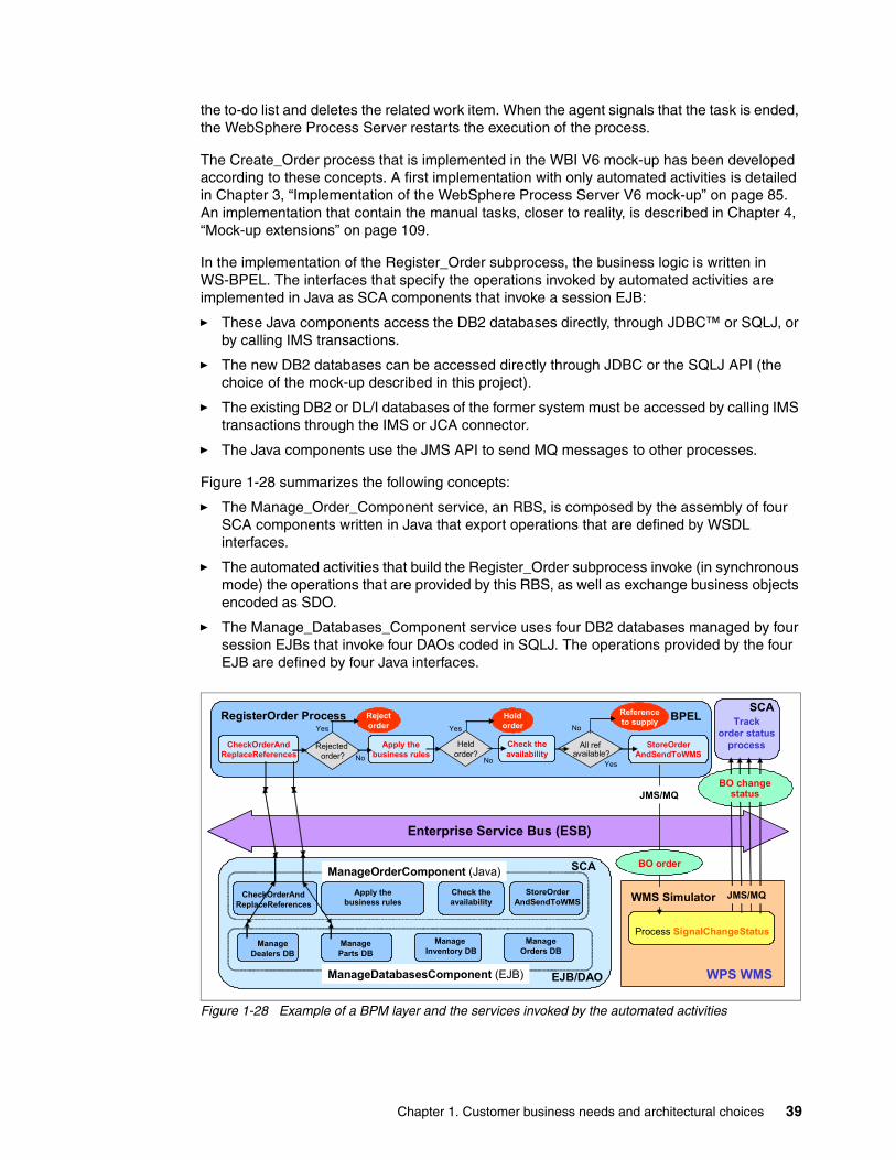
the to-do list and deletes the related work item. When the agent signals that the task is ended, the WebSphere Process Server restarts the execution of the process.
The Create_Order process that is implemented in the WBI V6 mock-up has been developed according to these concepts. A first implementation with only automated activities is detailed in Chapter 3, “Implementation of the WebSphere Process Server V6 mock-up” on page 85. An implementation that contain the manual tasks, closer to reality, is described in Chapter 4, “Mock-up extensions” on page 109.
In the implementation of the Register_Order subprocess, the business logic is written in WS-BPEL. The interfaces that specify the operations invoked by automated activities are implemented in Java as SCA components that invoke a session EJB:
� These Java components access the DB2 databases directly, through JDBC™ or SQLJ, or by calling IMS transactions.
� The new DB2 databases can be accessed directly through JDBC or the SQLJ API (the choice of the mock-up described in this project).
� The existing DB2 or DL/I databases of the former system must be accessed by calling IMS transactions through the IMS or JCA connector.
� The Java components use the JMS API to send MQ messages to other processes.
Figure 1-28 summarizes the following concepts:
� The Manage_Order_Component service, an RBS, is composed by the assembly of four SCA components written in Java that export operations that are defined by WSDL interfaces.
� The automated activities that build the Register_Order subprocess invoke (in synchronous mode) the operations that are provided by this RBS, as well as exchange business objects encoded as SDO.
� The Manage_Databases_Component service uses four DB2 databases managed by four session EJBs that invoke four DAOs coded in SQLJ. The operations provided by the four EJB are defined by four Java interfaces.
Figure 1-28 Example of a BPM layer and the services invoked by the automated activities
Trackorder status
process
SCARegisterOrder Process
Enterprise Service Bus (ESB)
Process SignalChangeStatus
WPS WMS
JMS/MQ
)
SCACheckOrderAnd
ReplaceReferencesCheck theavailability
ManageOrders DB
Manage Dealers DB
Manage Parts DB
Manage Inventory DB
Apply thebusiness rules
CheckOrderAndReplaceReferences
Apply thebusiness rules
Check theavailability
StoreOrderAndSendToWMS
BPELYes
Rejected order?
All refavailable?
Heldorder?
Rejectorder
Holdorder
Referenceto supply
StoreOrderAndSendToWMS
No No
NoYes
Yes
SCA
EJB/DAO
ManageOrderComponent (Java)
ManageDatabasesComponent (EJB)
BO change status
WMS Simulator
BO order
JMS/MQ
Chapter 1. Customer business needs and architectural choices 39
The Register_Order business process, modeled in WS-BPEL, is described in 2.3.4, “The Register_Order subprocess” on page 80. Its activities directly invoke services that are implemented by the SCA components written in Java and deployed in the same environment. In that case, the ESB is not really used.
Through the ESB, its connectors, and adapters, the Register_Order subprocess could transparently invoke services that are hosted in other environments. It could invoke external Web services, existing IMS transactions, SAP BAPI, and so on. These pieces of code have been encapsulated previously as RBS specified with well-defined WSDL interfaces.
For example, the prototype described in Chapter 5, “From the current architecture to the SOA: A migration experience” on page 127, explains that the reuse of existing IMS or DL/I transactions is an efficient means to reduce the costs and risks of a project. In that case, the ESB and the IMS or JCA connector can invoke these old transactions that were transformed previously in RBS or WSDL assets, by an integration specialist using WebSphere Integration Developer.
1.3.3 System z as the target platform
Like the existing system, the future system will be a strategic application and requires a high quality of service in terms of high availability, subsecond response time, and scalability. The main criteria of decision for the target platforms is the quality of service, the investment costs, the production costs, the ease of migration, and the durability of the solution.
� The OM and the WMS subsystems automate real-time processes and provide a better answer to business needs if they are full real-time systems. They require both high availability and excellent responses times.
� The SCM is a mixed subsystem. Some processes require real-time, but not all of them. SCM requires a lower availability than OM and WMS. The optimization algorithms require fast CPU and large memory resources.
� The packages that are pre-selected for implementing the WMS and SCM subsystems are UNIX or Linux® solutions (though running also on Microsoft Windows®), which today do not work on the z/OS platform. Therefore, UNIX platforms were considered to host these systems. They provide partitioning capabilities that allow a better sharing of resources than small, dedicated servers.
� The OM subsystem can be hosted on z/OS or AIX. The first version of the new OM subsystem needs to process about 300,000 orders every day; it may be extended to other countries. The OM subsystem will then have to sustain a charge of 500,000 orders or more every day, and it will require a 24x7 availability.
For the OM subsystem, two scenarios have been studied: an extended SAP solution and a specific realization under WebSphere. They both work on z/OS, but today only SAP under UNIX is in production at this customer site and there is no intent to move SAP applications under z/OS. Therefore, it was decided to develop the two initial mock-ups, the SAP solution and the WebSphere specific development, on an IBM System p™ server running AIX.
It was also decided to run the WebSphere specific application in a z/OS environment. In that perspective, the portability of the code from UNIX to z/OS was an additional objective of the “WBI V6” prototype.
40 Implementing and Testing SOA on IBM System z: A Real Customer Case
The new system is built by the integration of two software packages, SCM and WMS, with Java services specifically developed, mainly for the OM component. The target architecture is an instantiation of the generic SOA-BPM model that is implemented with the WebSphere Business Integration platform in which:
� The ESB supports all the exchanges between the main components.� The B2x portal provides a Web access to the offered services.� The B2B gateway manages all Web services exchanges with external partners, dealers
and suppliers.
This integration infrastructure has the following requirements:
� Support for a strong load with subsecond response time� High availability
The following sections describe the reasons for choosing the z/OS environment, the complete architecture of the full solution, and the steps for building the System z platform.
The final choice for OM: WebSphere and z/OSAfter the positive results in terms of functionality and performance of the WBI V6 mock-up, the final decision for the OM subsystem was to realize a WebSphere V6 specific application. Therefore, it was decided to use the System z platform for the OM component and the integration infrastructure, using Parallel Sysplex and the data sharing capabilities for availability and scalability. Performance numbers of the initial mock-up built with WebSphere Process Server Version 6 on the System p platform are provided in Appendix A, “Performance tests” on page 145.
The exploitation costs of the System z platform were considered competitive, in particular with the use of the System z Application Assist Processor (zAAP) to absorb the CPU load that is required by the Java code. To learn more about zAAP, refer to the following Web address:
http://www-03.ibm.com/systems/z/zaap/
Another reason for choosing the System z platform is that the customer already exploits several other strategic applications on this platform. The customer is aware of the qualities of this platform in terms of high availability, response times, and scalability.
Note: The z/OS platform was considered for the real-time subsystems and the integration infrastructure.
Chapter 1. Customer business needs and architectural choices 41
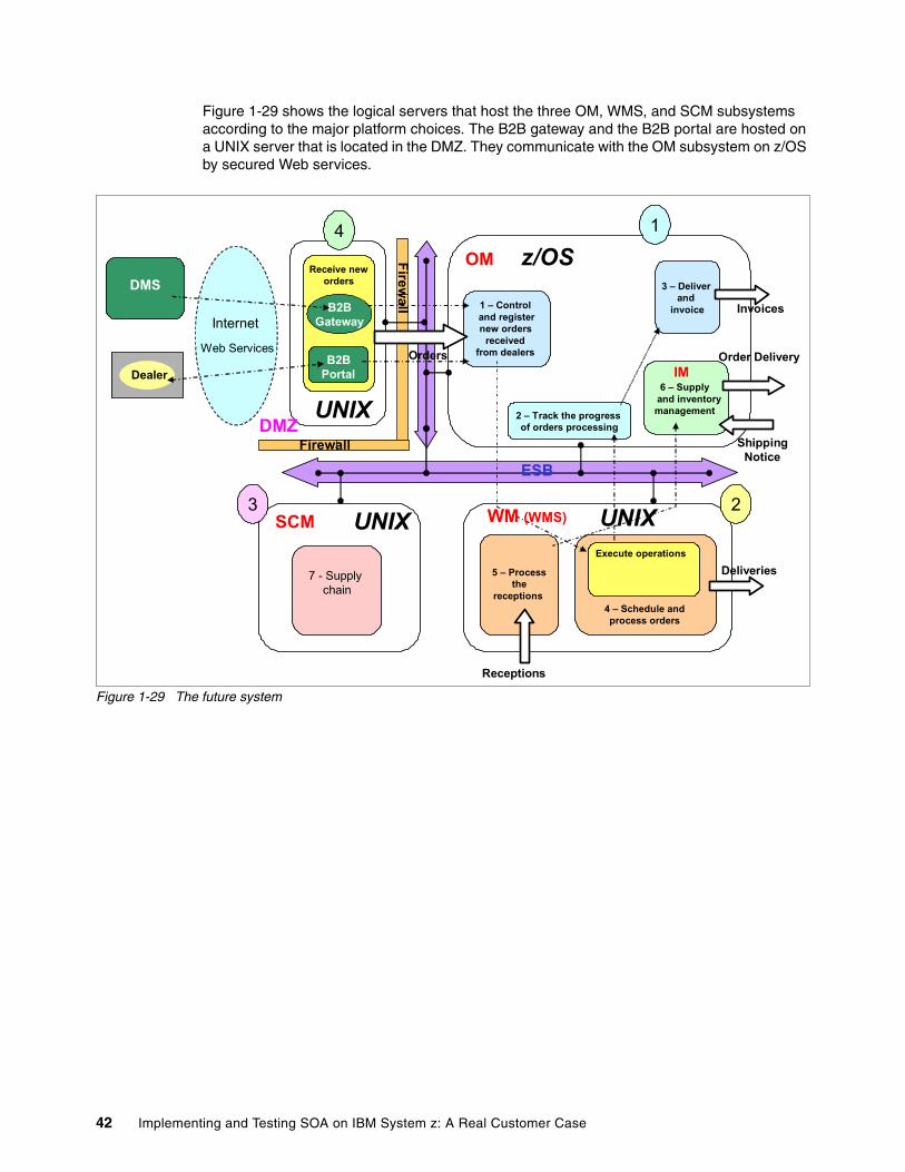
Figure 1-29 shows the logical servers that host the three OM, WMS, and SCM subsystems according to the major platform choices. The B2B gateway and the B2B portal are hosted on a UNIX server that is located in the DMZ. They communicate with the OM subsystem on z/OS by secured Web services.
Figure 1-29 The future system
Receive neworders
B2BGateway
B2BPortal
1 – Control and registernew orders
received from dealers
OM3 – Deliver
and invoice
4 – Schedule and process orders
Execute operations
5 – Processthe
receptions
7 - Supply chain
SCM
Dealer
DMS
2 – Track the progress of orders processing
1
3
Deliveries
Receptions
ShippingNotice
Firewall
Firewall
Orders
Invoices
6 – Supply and inventory management
IM
2
Order Delivery
UNIX UNIX
z/OS
UNIX
WM (WMS)
ESB
4
Internet
Web Services
DMZ
42 Implementing and Testing SOA on IBM System z: A Real Customer Case
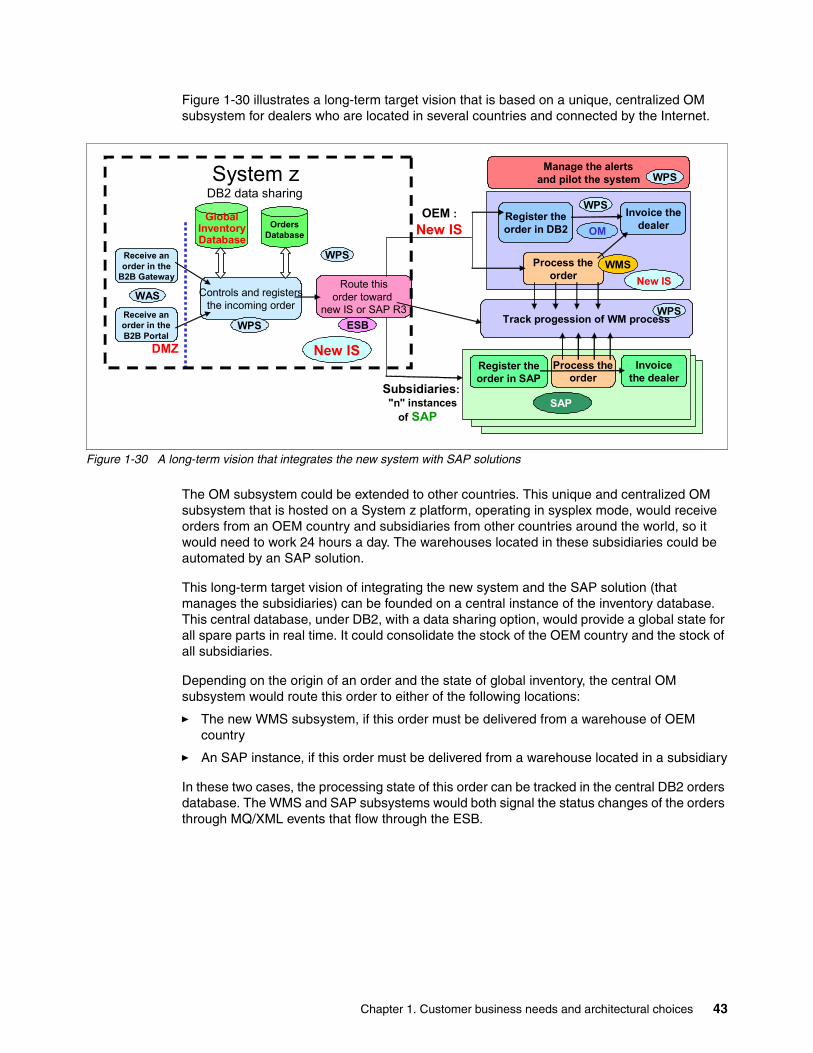
Figure 1-30 illustrates a long-term target vision that is based on a unique, centralized OM subsystem for dealers who are located in several countries and connected by the Internet.
Figure 1-30 A long-term vision that integrates the new system with SAP solutions
The OM subsystem could be extended to other countries. This unique and centralized OM subsystem that is hosted on a System z platform, operating in sysplex mode, would receive orders from an OEM country and subsidiaries from other countries around the world, so it would need to work 24 hours a day. The warehouses located in these subsidiaries could be automated by an SAP solution.
This long-term target vision of integrating the new system and the SAP solution (that manages the subsidiaries) can be founded on a central instance of the inventory database. This central database, under DB2, with a data sharing option, would provide a global state for all spare parts in real time. It could consolidate the stock of the OEM country and the stock of all subsidiaries.
Depending on the origin of an order and the state of global inventory, the central OM subsystem would route this order to either of the following locations:
� The new WMS subsystem, if this order must be delivered from a warehouse of OEM country
� An SAP instance, if this order must be delivered from a warehouse located in a subsidiary
In these two cases, the processing state of this order can be tracked in the central DB2 orders database. The WMS and SAP subsystems would both signal the status changes of the orders through MQ/XML events that flow through the ESB.
Controls and registers the incoming order
Process theorder
Invoice thedealer
Receive anorder in the
B2B Gateway
Track progession of WM process
Route thisorder toward
new IS or SAP R3Receive anorder in theB2B Portal
Manage the alertsand pilot the system
WAS
WMS
WPS
WPSWPS
Register theorder in DB2 OM
Process theorder
Invoicethe dealer
SAP
Register theorder in SAP
New IS
OEM :New IS
Subsidiaries:"n" instances
of SAP
New IS
OrdersDatabase
GlobalInventoryDatabase
ESB
DMZ
WPS
WPS
System zDB2 data sharing
Chapter 1. Customer business needs and architectural choices 43
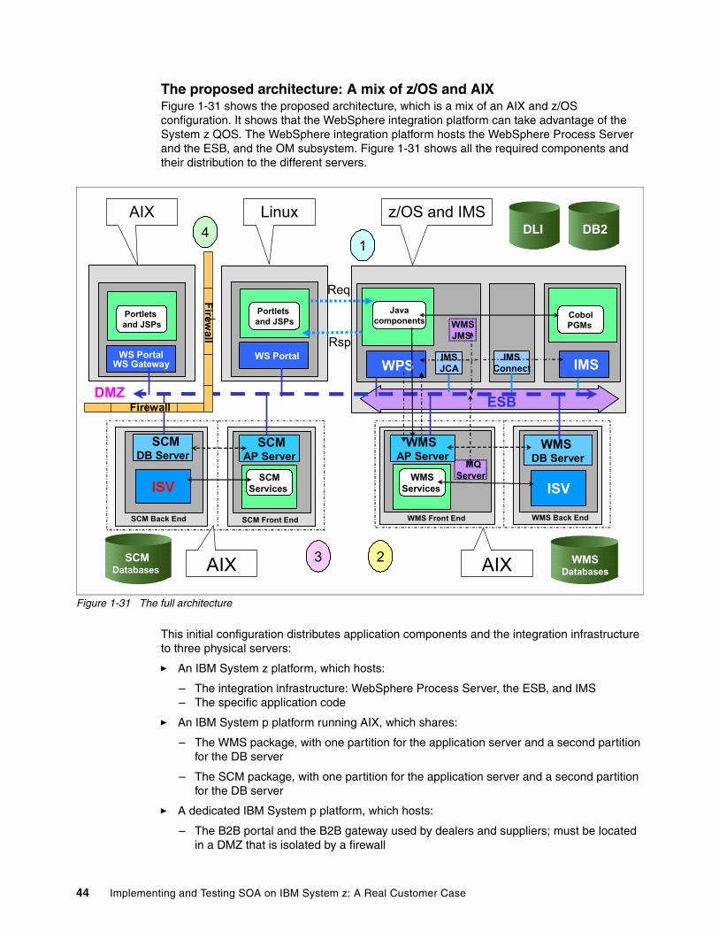
The proposed architecture: A mix of z/OS and AIX Figure 1-31 shows the proposed architecture, which is a mix of an AIX and z/OS configuration. It shows that the WebSphere integration platform can take advantage of the System z QOS. The WebSphere integration platform hosts the WebSphere Process Server and the ESB, and the OM subsystem. Figure 1-31 shows all the required components and their distribution to the different servers.
Figure 1-31 The full architecture
This initial configuration distributes application components and the integration infrastructure to three physical servers:
� An IBM System z platform, which hosts:
– The integration infrastructure: WebSphere Process Server, the ESB, and IMS – The specific application code
� An IBM System p platform running AIX, which shares:
– The WMS package, with one partition for the application server and a second partition for the DB server
– The SCM package, with one partition for the application server and a second partition for the DB server
� A dedicated IBM System p platform, which hosts:
– The B2B portal and the B2B gateway used by dealers and suppliers; must be located in a DMZ that is isolated by a firewall
WPS
DLI
ISV
IMS
DB2
WS Portal
Portletsand JSPs
WMSServices
WMSJMS
IMSConnect
IMSJCA
MQServer
CobolPGMs
Javacomponents
WMS DB Server
ISVSCM
Services
ESB
Rsp
Req
WMS Front End
SCMAP Server
WMSAP Server
SCM DB Server
SCM Back End WMS Back End SCM Front End
WS PortalWS Gateway
Portletsand JSPs
Firewall
DMZFirewall
3 2
41
AIX Linux z/OS and IMS
AIX AIXSCMDatabases
WMSDatabases
44 Implementing and Testing SOA on IBM System z: A Real Customer Case
The B2E portal, which is used to control the system, may be located in the intranet zone. It can be hosted by either one partition of the shared UNIX server or one z/Linux logical partition (LPAR) of the System z platform running Linux for z/OS.
The infrastructure and the application components are distributed as follows:
� On the System z platform:
– In a z/OS partition:
• The reused modules of the former system that is running with IMS and managing the former DL/I databases
• The WebSphere Process Server front end and the WebSphere back end that are managing the new DB2 databases: the BPEL or Java code that is implementing the logic of business processes (ABS) and the Java components that are implementing the services that support these processes (CBS)
• The ESB, which is comprised of the IBM WebSphere Enterprise Service Bus or IBM WebSphere Message Broker, the WebSphere Business Integration products adapters, and the J2EE or JCA connector
The ESB is hosted by z/OS to achieve most of the quality of services that are provided by Parallel Sysplex.
– In a Linux partition (this option is under investigation at the time of the writing):
• The WebSphere Portal Server, which implements the B2E portal
� On a shared UNIX server:
– The WMS package, with one partition for the application server and one instance of the ISV database server
– The SCM package, with one partition for the application server and one instance of the database server
– The WebSphere Portal Server, which implements the B2E portal (if the Linux on System z option is not confirmed)
� On a UNIX server that is located in the DMZ:
– The WebSphere Portal Server, which implements the B2B portal and the B2B gateway
Building the target System z platformTo achieve the most from the additional capabilities of the System z platform, such as using Linux, the sysplex architecture, or data sharing, requires additional expertise. Therefore, deployment of the target configuration is progressive. The three main steps are:
1. Install the WebSphere Process Server and the DB2 servers in a z/OS partition and then use Parallel Sysplex and data sharing.
2. Install the B2E portal under Linux on a System z platform using HiperSockets™ links.
3. Install a secured DMZ infrastructure, with an integrated firewall, on the System z platform and the B2B portal in a Linux partition on the System z platform using a HiperSockets connection.
Chapter 1. Customer business needs and architectural choices 45
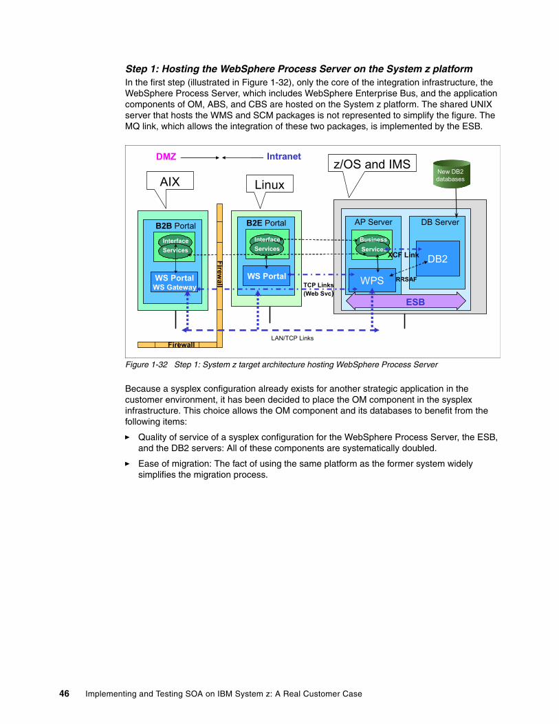
Step 1: Hosting the WebSphere Process Server on the System z platformIn the first step (illustrated in Figure 1-32), only the core of the integration infrastructure, the WebSphere Process Server, which includes WebSphere Enterprise Bus, and the application components of OM, ABS, and CBS are hosted on the System z platform. The shared UNIX server that hosts the WMS and SCM packages is not represented to simplify the figure. The MQ link, which allows the integration of these two packages, is implemented by the ESB.
Figure 1-32 Step 1: System z target architecture hosting WebSphere Process Server
Because a sysplex configuration already exists for another strategic application in the customer environment, it has been decided to place the OM component in the sysplex infrastructure. This choice allows the OM component and its databases to benefit from the following items:
� Quality of service of a sysplex configuration for the WebSphere Process Server, the ESB, and the DB2 servers: All of these components are systematically doubled.
� Ease of migration: The fact of using the same platform as the former system widely simplifies the migration process.
LAN/TCP Links
DB Server
DB2
BusinessServices
WPS
AP Server
XCF Link
RRSAF
B2B Portal B2E Portal
WS PortalWS Gateway
WS PortalTCP Links(Web Svc)
Firewall
Intranet
ESB
Firewall
DMZ
AIX Linuxz/OS and IMS
InterfaceServices
InterfaceServices
New DB2databases
46 Implementing and Testing SOA on IBM System z: A Real Customer Case
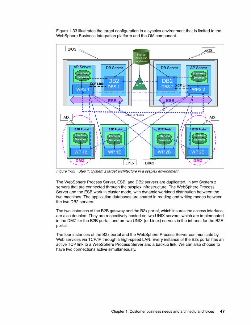
Figure 1-33 illustrates the target configuration in a sysplex environment that is limited to the WebSphere Business Integration platform and the OM component.
Figure 1-33 Step 1: System z target architecture in a sysplex environment
The WebSphere Process Server, ESB, and DB2 servers are duplicated, in two System z servers that are connected through the sysplex infrastructure. The WebSphere Process Server and the ESB work in cluster mode, with dynamic workload distribution between the two machines. The application databases are shared in reading and writing modes between the two DB2 servers.
The two instances of the B2B gateway and the B2x portal, which insures the access interface, are also doubled. They are respectively hosted on two UNIX servers, which are implemented in the DMZ for the B2B portal, and on two UNIX (or Linux) servers in the intranet for the B2E portal.
The four instances of the B2x portal and the WebSphere Process Server communicate by Web services via TCP/IP through a high-speed LAN. Every instance of the B2x portal has an active TCP link to a WebSphere Process Server and a backup link. We can also choose to have two connections active simultaneously.
Sharednew DB2
databases
BusinessServices
AP Server
WPS 2
DB Server
DB2DBS 1
DB Server
DB2DBS 2XCF
BusinessServices
AP Server
WPS 1
LAN/TCP Links
XCF LinkXCF Link
B2B Portal B2E Portal
WP 1B WP 1E
Linux Server
B2B PortalB2E Portal
WP 2EWP 2B
ESBESB
DMZ DMZ
AIX AIX
Linux Linux
z/OS z/OS
InterfaceServices
InterfaceServices
InterfaceServices
InterfaceServices
Chapter 1. Customer business needs and architectural choices 47
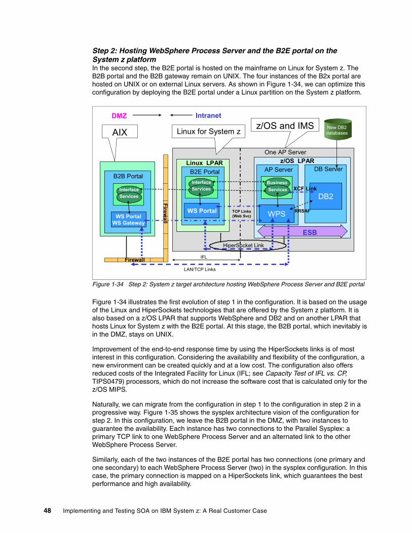
Step 2: Hosting WebSphere Process Server and the B2E portal on the System z platformIn the second step, the B2E portal is hosted on the mainframe on Linux for System z. The B2B portal and the B2B gateway remain on UNIX. The four instances of the B2x portal are hosted on UNIX or on external Linux servers. As shown in Figure 1-34, we can optimize this configuration by deploying the B2E portal under a Linux partition on the System z platform.
Figure 1-34 Step 2: System z target architecture hosting WebSphere Process Server and B2E portal
Figure 1-34 illustrates the first evolution of step 1 in the configuration. It is based on the usage of the Linux and HiperSockets technologies that are offered by the System z platform. It is also based on a z/OS LPAR that supports WebSphere and DB2 and on another LPAR that hosts Linux for System z with the B2E portal. At this stage, the B2B portal, which inevitably is in the DMZ, stays on UNIX.
Improvement of the end-to-end response time by using the HiperSockets links is of most interest in this configuration. Considering the availability and flexibility of the configuration, a new environment can be created quickly and at a low cost. The configuration also offers reduced costs of the Integrated Facility for Linux (IFL; see Capacity Test of IFL vs. CP, TIPS0479) processors, which do not increase the software cost that is calculated only for the z/OS MIPS.
Naturally, we can migrate from the configuration in step 1 to the configuration in step 2 in a progressive way. Figure 1-35 shows the sysplex architecture vision of the configuration for step 2. In this configuration, we leave the B2B portal in the DMZ, with two instances to guarantee the availability. Each instance has two connections to the Parallel Sysplex: a primary TCP link to one WebSphere Process Server and an alternated link to the other WebSphere Process Server.
Similarly, each of the two instances of the B2E portal has two connections (one primary and one secondary) to each WebSphere Process Server (two) in the sysplex configuration. In this case, the primary connection is mapped on a HiperSockets link, which guarantees the best performance and high availability.
DB Server
DB2
One AP Server
BusinessServices
WPS
AP Server
XCF Link
RRSAF
InterfaceServices
B2B PortalB2E Portal
WS PortalWS Gateway
WS Portal
HiperSocket Link
z/OS LPAR
Firewall
DMZ Intranet
ESB
LAN/TCP Links
Firewall IFL
Linux LPAR
AIX Linux for System z z/OS and IMS
InterfaceServices
New DB2databases
TCP Links(Web Svc)
48 Implementing and Testing SOA on IBM System z: A Real Customer Case
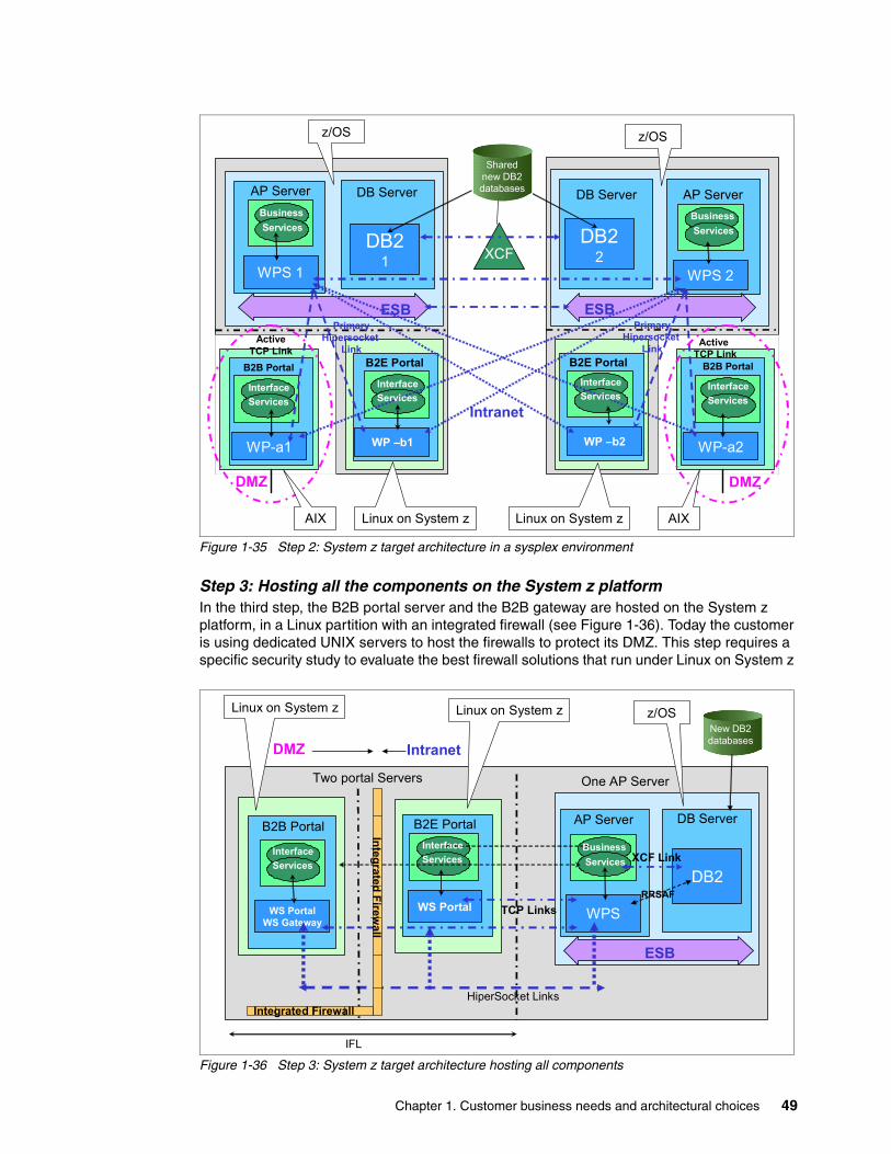
Figure 1-35 Step 2: System z target architecture in a sysplex environment
Step 3: Hosting all the components on the System z platformIn the third step, the B2B portal server and the B2B gateway are hosted on the System z platform, in a Linux partition with an integrated firewall (see Figure 1-36). Today the customer is using dedicated UNIX servers to host the firewalls to protect its DMZ. This step requires a specific security study to evaluate the best firewall solutions that run under Linux on System z
Figure 1-36 Step 3: System z target architecture hosting all components
DB Server
DB21
DB Server
DB22XCF
AP Server
WPS 1
AP Server
WPS 2
WP –b1
B2E Portal
WP –b2
B2E Portal
ESBESBPrimary
HipersocketLink
Linux Server
B2B Portal
WP-a2
PrimaryHipersocket
Link
B2B Portal
WP-a1
Active TCP Link
Active TCP Link
DMZ DMZ
Intranet
AIX AIXLinux on System z Linux on System z
z/OS z/OS
BusinessServices
BusinessServices
InterfaceServices
InterfaceServices
InterfaceServices
InterfaceServices
Sharednew DB2databases
DB Server
DB2
One AP Server
WPS
AP Server
XCF Link
TCP LinksRRSAF
B2B Portal B2E Portal
WS PortalWS Gateway
WS Portal
HiperSocket Links
IFL
Integrated Firewall
DMZ Intranet
ESB
Integrated Firewall
z/OSLinux on System z Linux on System z
InterfaceServices
InterfaceServices
BusinessServices
New DB2databases
Two portal Servers
Chapter 1. Customer business needs and architectural choices 49
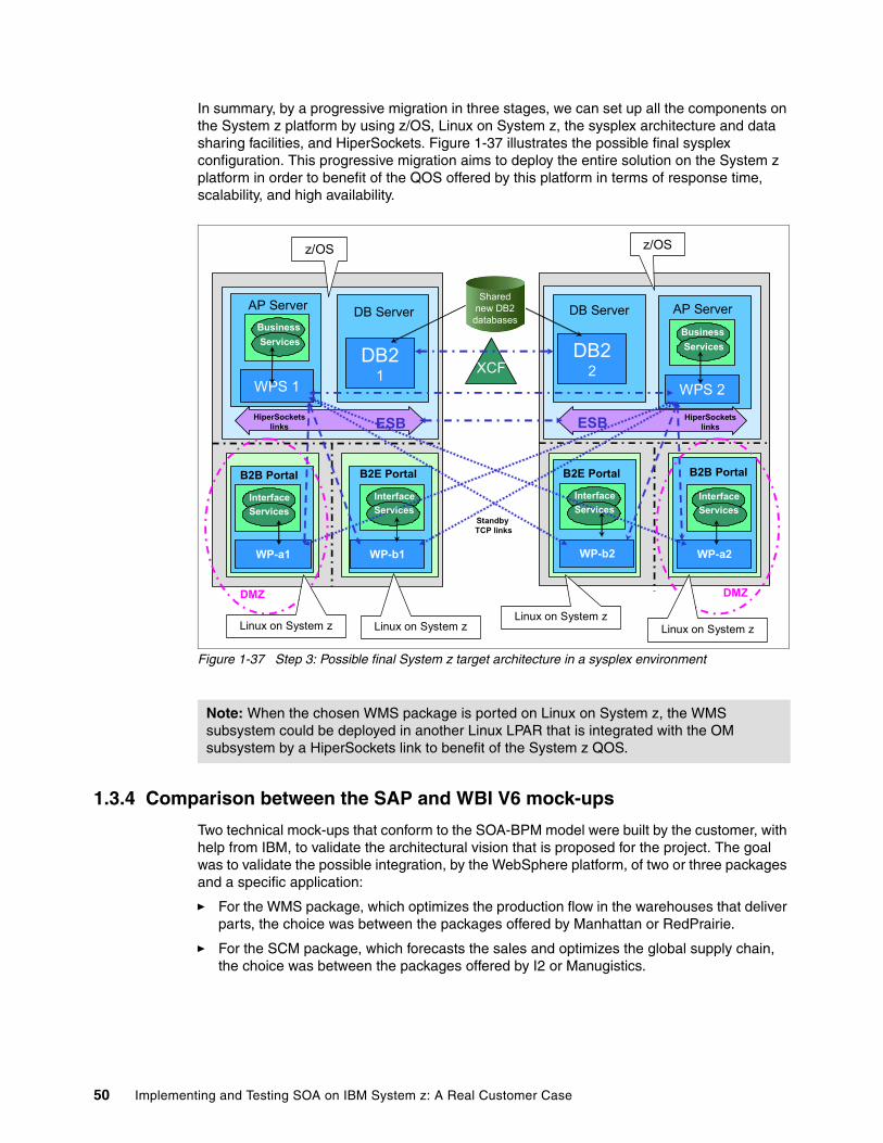
In summary, by a progressive migration in three stages, we can set up all the components on the System z platform by using z/OS, Linux on System z, the sysplex architecture and data sharing facilities, and HiperSockets. Figure 1-37 illustrates the possible final sysplex configuration. This progressive migration aims to deploy the entire solution on the System z platform in order to benefit of the QOS offered by this platform in terms of response time, scalability, and high availability.
Figure 1-37 Step 3: Possible final System z target architecture in a sysplex environment
1.3.4 Comparison between the SAP and WBI V6 mock-ups
Two technical mock-ups that conform to the SOA-BPM model were built by the customer, with help from IBM, to validate the architectural vision that is proposed for the project. The goal was to validate the possible integration, by the WebSphere platform, of two or three packages and a specific application:
� For the WMS package, which optimizes the production flow in the warehouses that deliver parts, the choice was between the packages offered by Manhattan or RedPrairie.
� For the SCM package, which forecasts the sales and optimizes the global supply chain, the choice was between the packages offered by I2 or Manugistics.
Note: When the chosen WMS package is ported on Linux on System z, the WMS subsystem could be deployed in another Linux LPAR that is integrated with the OM subsystem by a HiperSockets link to benefit of the System z QOS.
B2B Portal
WP-a2
DB Server
DB21
DB Server
DB22XCF
B2B Portal
WP-a1
AP Server
WPS 1
AP Server
WPS 2
WP-b1
Standby TCP links
B2E Portal
WP-b2
B2E Portal
ESB HiperSocketslinksESBHiperSockets
links
DMZDMZ
InterfaceServices
InterfaceServices
InterfaceServices
InterfaceServices
BusinessServices
BusinessServices
Sharednew DB2
databases
Linux on System z Linux on System zLinux on System z
Linux on System z
z/OSz/OS
50 Implementing and Testing SOA on IBM System z: A Real Customer Case
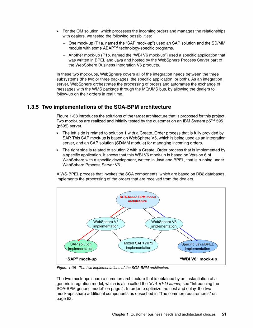
� For the OM solution, which processes the incoming orders and manages the relationships with dealers, we tested the following possibilities:
– One mock-up (P1a, named the “SAP mock-up”) used an SAP solution and the SD/MM module with some ABAP™ technology-specific programs.
– Another mock-up (P1b, named the “WBI V6 mock-up”) used a specific application that was written in BPEL and Java and hosted by the WebSphere Process Server part of the WebSphere Business Integration V6 products.
In these two mock-ups, WebSphere covers all of the integration needs between the three subsystems (the two or three packages, the specific application, or both). As an integration server, WebSphere orchestrates the processing of orders and automates the exchange of messages with the WMS package through the MQ/JMS bus, by allowing the dealers to follow-up on their orders in real time.
1.3.5 Two implementations of the SOA-BPM architecture
Figure 1-38 introduces the solutions of the target architecture that is proposed for this project. Two mock-ups are realized and initially tested by the customer on an IBM System p5™ 595 (p595) server.
� The left side is related to solution 1 with a Create_Order process that is fully provided by SAP. This SAP mock-up is based on WebSphere V5, which is being used as an integration server, and an SAP solution (SD/MM module) for managing incoming orders.
� The right side is related to solution 2 with a Create_Order process that is implemented by a specific application. It shows that this WBI V6 mock-up is based on Version 6 of WebSphere with a specific development, written in Java and BPEL, that is running under WebSphere Process Server V6.
A WS-BPEL process that invokes the SCA components, which are based on DB2 databases, implements the processing of the orders that are received from the dealers.
Figure 1-38 The two implementations of the SOA-BPM architecture
The two mock-ups share a common architecture that is obtained by an instantiation of a generic integration model, which is also called the SOA-BPM model; see “Introducing the SOA-BPM generic model” on page 4. In order to optimize the cost and delay, the two mock-ups share additional components as described in “The common requirements” on page 52.
Specific Java/BPELimplementation
SAP solutionimplementation
SOA-based BPM modelarchitecture
WebSphere V6implementation
WebSphere V5implementation
Mixed SAP+WPSimplementation
“SAP” mock-up “WBI V6” mock-up
Chapter 1. Customer business needs and architectural choices 51
This common architecture has the following characteristics:
� It matches the three studied solutions: SAP, specific, or mixed.� It makes the best usage of the WebSphere platform.� It provides the best compromise between resources and performances.� It fully conforms to the generic SOA-BPM model.
This book mainly describes the WBI V6 mock-up, based on WebSphere Process Server Version 6, to evaluate new technologies such as BPM and portal. To be complete, in the following section, we describe the principles of the SAP mock-up, in which WebSphere V5 is used mainly as an integration server.
Both the WBI V6 mock-up and the SAP mock-up follow the same requirements and implement the same type of architecture.
The common requirementsThe two mock-ups implement the same functionality and processes:
� The Receive_incoming_orders_from_the_dealers process
The new orders are injected into the prototypes by two types of injectors that work with the following protocols:
– MQ/JMS to simulate the orders that are received through the B2B gateway– Web services (SOAP over HTTP) for the orders that are entered in the B2B portal
� The Control_and_register_an_incoming_order process, by invoking the standard SAP Create_Order process (the case in the SAP mock-up) or a specific WS-BPEL process that is implemented under WebSphere Process Server and managing DB2 databases (the case in the WBI V6 mock-up)
� The Route_this_Order process to the component that simulates an actual WMS
In our mock-ups, this is a simulator that works under WebSphere Process Server.
� The simulation of the processing of the order in WMS and the tracking of its progression
The WebSphere Process Server WMS simulator signals the major events that occur in the process with outgoing MQ/XML messages.
� In SAP or DB2, records of the current state of the order in the respective warehouse
The MQ/XML messages sent by the WMS simulator activate an SAP or WebSphere Process Server process that records these changes of status into its orders database.
� Simulation of the queries that the dealers execute in order to visualize the progress report of their orders
These queries are injected by a J2EE simulator that activates the consultation of pending orders in the SAP or DB2 database.
� Simulation of the reception of parts that come from suppliers in order to update the SAP or the DB2 inventory database, with a simulator process running under the J2EE front end instead of the actual WMS package
52 Implementing and Testing SOA on IBM System z: A Real Customer Case
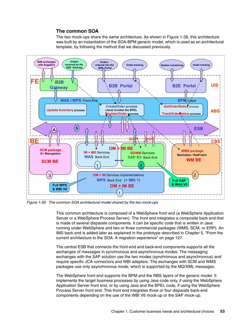
The common SOAThe two mock-ups share the same architecture. As shown in Figure 1-39, this architecture was built by an instantiation of the SOA-BPM generic model, which is used as an architectural template, by following the method that we discussed previously.
Figure 1-39 The common SOA architectural model shared by the two mock-ups
This common architecture is composed of a WebSphere front end (a WebSphere Application Server or a WebSphere Process Server). The front end integrates a composite back end that is made of several disparate components. It can be specific code that is written in Java running under WebSphere and two or three commercial packages (WMS, SCM, or ERP). An IMS back end is added later as explained in the prototype described in Chapter 5, “From the current architecture to the SOA: A migration experience” on page 127.
The central ESB that connects the front-end and back-end components supports all the exchanges of messages in synchronous and asynchronous modes. The messaging exchanges with the SAP solution use the two modes (synchronous and asynchronous) and require specific JCA connectors and WBI adapters. The exchanges with SCM and WMS packages use only asynchronous mode, which is supported by the MQ/XML messages.
The WebSphere front end supports the BPM and the RBS layers of the generic model. It implements the target business processes by using Java code only, if using the WebSphere Application Server front end, or by using Java and the BPEL code, if using the WebSphere Process Server front end. This front end integrates three or four disparate back-end components depending on the use of the WBI V6 mock-up or the SAP mock-up.
B2BGateway
ESB
FE
BE CBS
WAS / WPS Front End
SCM packageI2 / Manugistics
WMS packageManhattan / RedPrairie
ABS
A
B2B Portal
WM BE
2
SCM BE
3
S
UISB2E Portal
BPM Layer
CreateOrder process(Java) invokes the BPEL RegisterOrder process
GetOrderStatus process
TrackOrderStatus processUpdate Inventory process
IM + MD ServicesWAS Back End
1
OM + IM BESD/MM Services
SAP R3 Back End
IDOCBAPI
Order trackingSystem monitoringOrders
received by the B2B Gateway
Orders entered into the
B2B PortalOrder tracking
OM + IM Services implementationsWPS Back End (+ IMS ?)
1OM + IM BE
4
B2B exchangeswith Suppliers
Full SAP & WAS V5Full WPS
& WBI V6
Chapter 1. Customer business needs and architectural choices 53
A B2B gateway and a B2B portal allow the dealers to invoke the processes and services that are exposed by the WebSphere front end. Incoming orders are received in the B2B gateway or typed in the B2B portal. The B2B portal also supports order tracking.
A B2E portal allows the specialized operators that support the dealers’ relationships to monitor the application and follow-up on the status of the orders that are received from network.
The following major processes are implemented in the two mock-ups:
� The Create_Order process, which receives, controls, and registers an incoming order
� The Track_Order_Status process, which tracks the major status changes for orders that are processed by WMS
� The Get_Order_Status process, which displays the current state of pending orders to requesting dealers
� The Update_Inventory process, which updates the level of inventory after receiving parts from the suppliers
The main implementation rule of BPM, which advises to clearly separate the logic of a process from the services that are invoked by its automatic activities, is fully respected. Through the ESB, these common processes invoke well-defined services that are exposed by the RBS layer. These services are implemented by the back-end components.
In the two mock-ups, the WMS and SCM back ends are the same. They are implemented by two commercial packages that are connected to the ESB in asynchronous mode. The Re-supplying & Inventory Management (IM) function, which is not provided by the SCM package, must be implemented by specific code that is deployed in WebSphere.
The main difference between the full WebSphere architecture and the SAP solution alternative is in regard to the OM back end, which is also called “OM+IM back end” because it contains the inventory management functions as well.
� The OM+IM back end is composed of only specific Java code in the full WebSphere V6 solution.
� The OM+IM back end is a composite component that is made of two parts (an SAP back end and a WebSphere Application Server back end) with SD/MM modules (for SAP) that are completed by specific Java code (for WebSphere Application Server) in the SAP solution.
This OM+IM back end is connected to the ESB in both synchronous and asynchronous modes.
54 Implementing and Testing SOA on IBM System z: A Real Customer Case
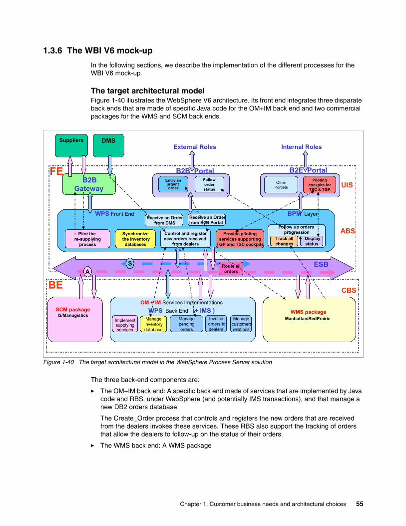
1.3.6 The WBI V6 mock-up
In the following sections, we describe the implementation of the different processes for the WBI V6 mock-up.
The target architectural modelFigure 1-40 illustrates the WebSphere V6 architecture. Its front end integrates three disparate back ends that are made of specific Java code for the OM+IM back end and two commercial packages for the WMS and SCM back ends.
Figure 1-40 The target architectural model in the WebSphere Process Server solution
The three back-end components are:
� The OM+IM back end: A specific back end made of services that are implemented by Java code and RBS, under WebSphere (and potentially IMS transactions), and that manage a new DB2 orders database
The Create_Order process that controls and registers the new orders that are received from the dealers invokes these services. These RBS also support the tracking of orders that allow the dealers to follow-up on the status of their orders.
� The WMS back end: A WMS package
DMSSuppliers
B2BGateway
ESB
Invoiceorders todealers
FE
BE
Implementsupplyingservices
CBS
Manageinventorydatabase
OM + IM Services implementationsWPS Back End (+ IMS )
Managecustomersrelations
Follow up orders progression
Displaystatus
Track allchanges
WPS Front End
Pilot the re-supplying
process
Provide pilotingservices supporting
TGP and TSC cockpits
SCM packageI2/Manugistics
WMS packageManhattan/RedPrairie
Synchronizethe inventorydatabases
ABS
Pilotingcockpits forTSC & TGP
OtherPortlets
Route allordersA
B2B PortalEntry anurgent order
Followorderstatus
S
UIS
Managependingorders
Control and registernew orders received
from dealers
Receive an Orderfrom DMS
Receive an Orderfrom B2B Portal
B2E Portal
BPM Layer
External Roles Internal Roles
Chapter 1. Customer business needs and architectural choices 55
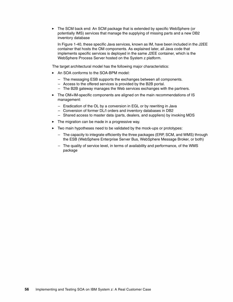
� The SCM back end: An SCM package that is extended by specific WebSphere (or potentially IMS) services that manage the supplying of missing parts and a new DB2 inventory database
In Figure 1-40, these specific Java services, known as IM, have been included in the J2EE container that hosts the OM components. As explained later, all Java code that implements specific services is deployed in the same J2EE container, which is the WebSphere Process Server hosted on the System z platform.
The target architectural model has the following major characteristics:
� An SOA conforms to the SOA-BPM model:
– The messaging ESB supports the exchanges between all components.– Access to the offered services is provided by the B2B portal.– The B2B gateway manages the Web services exchanges with the partners.
� The OM+IM-specific components are aligned on the main recommendations of IS management:
– Eradication of the OL by a conversion in EGL or by rewriting in Java– Conversion of former DL/I orders and inventory databases in DB2– Shared access to master data (parts, dealers, and suppliers) by invoking MDS
� The migration can be made in a progressive way.
� Two main hypotheses need to be validated by the mock-ups or prototypes:
– The capacity to integrate efficiently the three packages (ERP, SCM, and WMS) through the ESB (WebSphere Enterprise Server Bus, WebSphere Message Broker, or both)
– The quality of service level, in terms of availability and performance, of the WMS package
56 Implementing and Testing SOA on IBM System z: A Real Customer Case
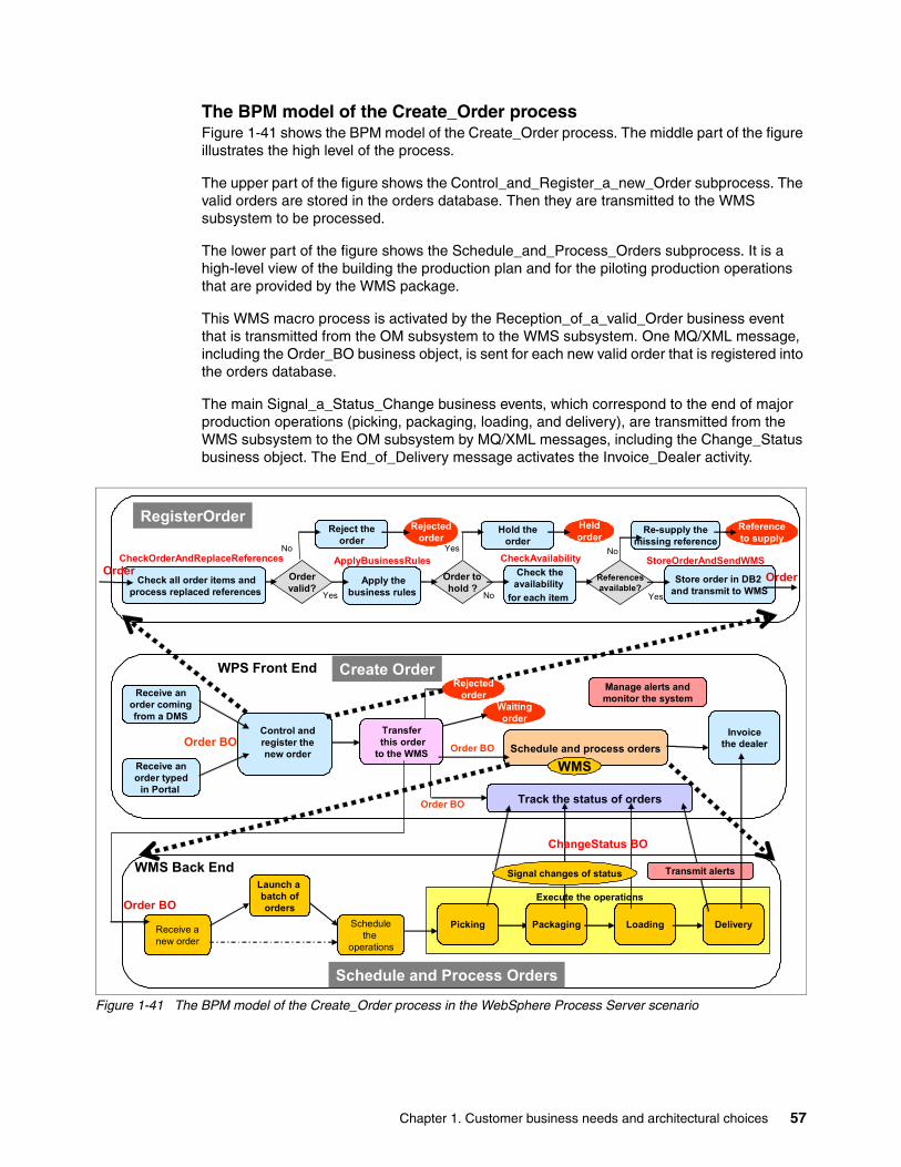
The BPM model of the Create_Order processFigure 1-41 shows the BPM model of the Create_Order process. The middle part of the figure illustrates the high level of the process.
The upper part of the figure shows the Control_and_Register_a_new_Order subprocess. The valid orders are stored in the orders database. Then they are transmitted to the WMS subsystem to be processed.
The lower part of the figure shows the Schedule_and_Process_Orders subprocess. It is a high-level view of the building the production plan and for the piloting production operations that are provided by the WMS package.
This WMS macro process is activated by the Reception_of_a_valid_Order business event that is transmitted from the OM subsystem to the WMS subsystem. One MQ/XML message, including the Order_BO business object, is sent for each new valid order that is registered into the orders database.
The main Signal_a_Status_Change business events, which correspond to the end of major production operations (picking, packaging, loading, and delivery), are transmitted from the WMS subsystem to the OM subsystem by MQ/XML messages, including the Change_Status business object. The End_of_Delivery message activates the Invoice_Dealer activity.
Figure 1-41 The BPM model of the Create_Order process in the WebSphere Process Server scenario
Schedule and process orders
Receive anew order
Launch a batch oforders
Schedulethe
operations
Schedule and Process Orders
Create Order
Order BO
Receive anorder comingfrom a DMS
Waitingorder
Execute the operations
Packaging Loading DeliveryPicking
WMS Back End
Track the status of orders
Transferthis order
to the WMS
WPS Front End
Transmit alerts
Order BO
Receive anorder typed
in Portal
Manage alerts andmonitor the system
WMS
Signal changes of status
Order BO
Referencesavailable?
Yes
No
Re-supply themissing reference
Reject theorder
Rejectedorder
No
Apply thebusiness rules Yes
CheckOrderAndReplaceReferences CheckAvailabilityApplyBusinessRules StoreOrderAndSendWMSOrdervalid?
Order tohold ?
Hold theorder
Heldorder
Yes
Referenceto supply
Check all order items andprocess replaced references
Check theavailability
for each item
Store order in DB2 and transmit to WMS
RegisterOrder
OrderOrder
No
Control andregister the new order
Order BOInvoice
the dealer
ChangeStatus BO
Rejectedorder
Chapter 1. Customer business needs and architectural choices 57
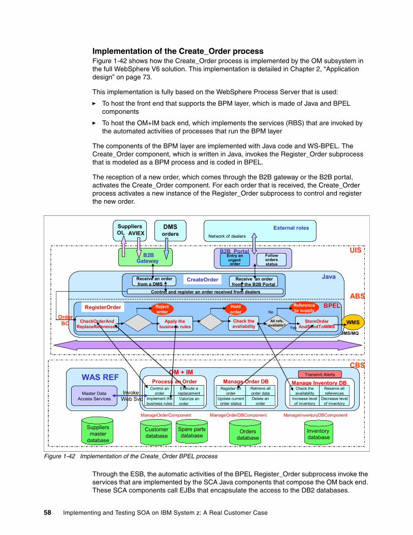
Implementation of the Create_Order processFigure 1-42 shows how the Create_Order process is implemented by the OM subsystem in the full WebSphere V6 solution. This implementation is detailed in Chapter 2, “Application design” on page 73.
This implementation is fully based on the WebSphere Process Server that is used:
� To host the front end that supports the BPM layer, which is made of Java and BPEL components
� To host the OM+IM back end, which implements the services (RBS) that are invoked by the automated activities of processes that run the BPM layer
The components of the BPM layer are implemented with Java code and WS-BPEL. The Create_Order component, which is written in Java, invokes the Register_Order subprocess that is modeled as a BPM process and is coded in BPEL.
The reception of a new order, which comes through the B2B gateway or the B2B portal, activates the Create_Order component. For each order that is received, the Create_Order process activates a new instance of the Register_Order subprocess to control and register the new order.
Figure 1-42 Implementation of the Create_Order BPEL process
Through the ESB, the automatic activities of the BPEL Register_Order subprocess invoke the services that are implemented by the SCA Java components that compose the OM back end. These SCA components call EJBs that encapsulate the access to the DB2 databases.
RegisterOrder Process
UIS
CBS
Inventory database
Manage Inventory DB
OM + IM Transmit Alerts
Increase levelof inventory
Check theavailability
Decrease levelof inventory
Reserve allreferences
Customerdatabase
Ordersdatabase
Manage Order DB
Update currentorder status
Register anorder
Delete anorder
Retrieve allorder data
Process an Order
Implement thebusiness rules
Control anorder
Execute areplacementValorize anorder
ManageOrderComponent ManageOrderDBComponent
Spare partsdatabase
Master DataAccess Services
WAS REF
JMS/MQ
CheckOrderAndReplaceReferences
Apply thebusiness rules
Check theavailability
StoreOrderAndSendToWMS
BPEL
All refs.available?
Rejectorder
Holdorder
Referenceto supplyNo
Yes
DMSorders
SuppliersOL AVIEX
B2BGateway
Network of dealers
B2B PortalEntry anurgent order
Followordersstatus
External roles
ABS
Receive an orderfrom a DMS
Receive an orderfrom the B2B Portal
Java
ManageInventoryDBComponent
Invoke Web Svc
OrderBO
Control and register an order received from dealers
WMS
CreateOrder
RegisterOrder
Suppliersmaster
database
58 Implementing and Testing SOA on IBM System z: A Real Customer Case
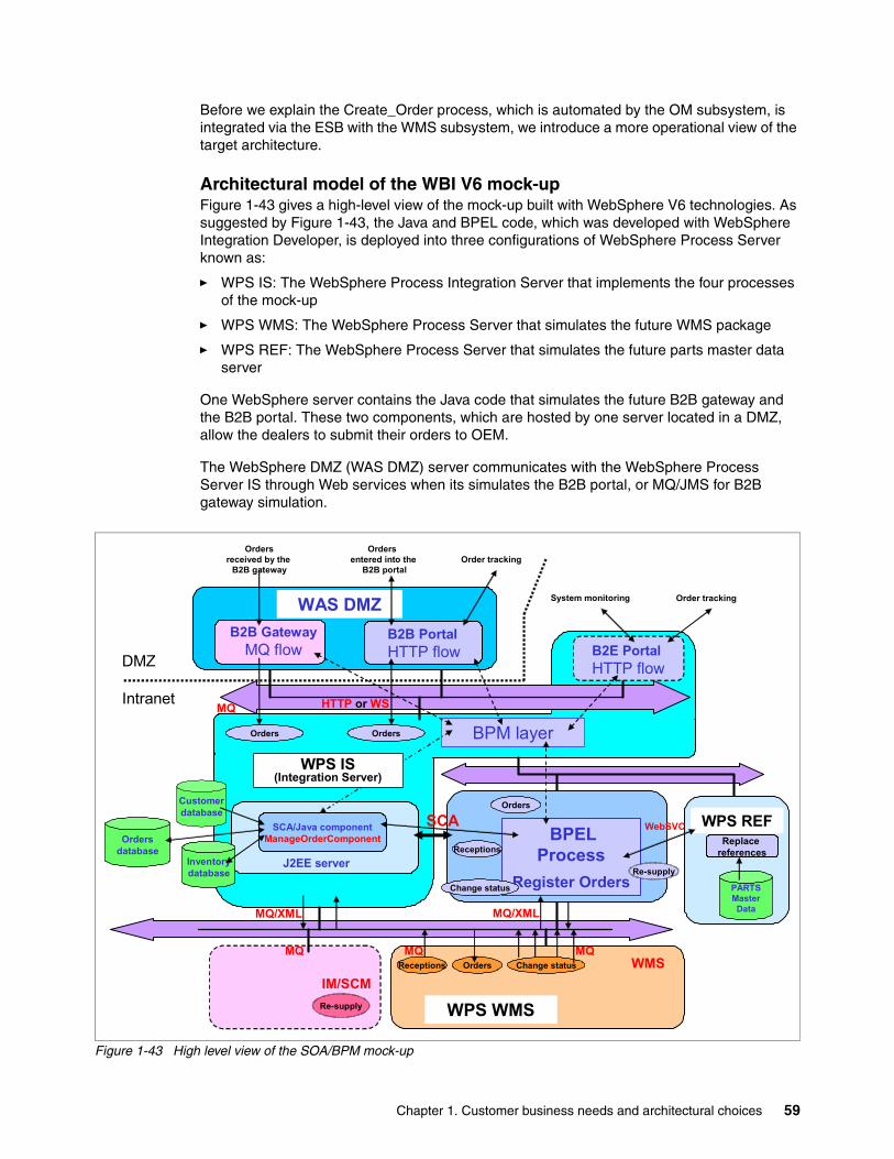
Before we explain the Create_Order process, which is automated by the OM subsystem, is integrated via the ESB with the WMS subsystem, we introduce a more operational view of the target architecture.
Architectural model of the WBI V6 mock-upFigure 1-43 gives a high-level view of the mock-up built with WebSphere V6 technologies. As suggested by Figure 1-43, the Java and BPEL code, which was developed with WebSphere Integration Developer, is deployed into three configurations of WebSphere Process Server known as:
� WPS IS: The WebSphere Process Integration Server that implements the four processes of the mock-up
� WPS WMS: The WebSphere Process Server that simulates the future WMS package
� WPS REF: The WebSphere Process Server that simulates the future parts master data server
One WebSphere server contains the Java code that simulates the future B2B gateway and the B2B portal. These two components, which are hosted by one server located in a DMZ, allow the dealers to submit their orders to OEM.
The WebSphere DMZ (WAS DMZ) server communicates with the WebSphere Process Server IS through Web services when its simulates the B2B portal, or MQ/JMS for B2B gateway simulation.
Figure 1-43 High level view of the SOA/BPM mock-up
Orders BPM layer
DMZ
Intranet
B2B PortalHTTP flow
B2B GatewayMQ flow
WAS DMZ
WMSIM/SCM
WPS WMSRe-supply
MQ/XML
MQ MQ
Orders
MQ HTTP or WS
Change statusOrdersReceptions
Ordersreceived by the
B2B gateway
Orders entered into the
B2B portal
Order tracking
Order tracking
MQ
WPS REFBPEL
ProcessRegister Orders PARTS
MasterData
Replace references
MQ/XML
WebSVC
Re-supply
Orders
Change status
ReceptionsInventorydatabase
Ordersdatabase
Customerdatabase
J2EE server
SCA/Java componentManageOrderComponent
SCA
WPS IS(Integration Server)
B2E PortalHTTP flow
System monitoring
Chapter 1. Customer business needs and architectural choices 59
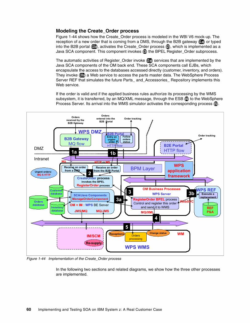
Modeling the Create_Order processFigure 1-44 shows how the Create_Order process is modeled in the WBI V6 mock-up. The reception of a new order that is coming from a DMS, through the B2B gateway (1a) or typed into the B2B portal (1b), activates the Create_Order process (2), which is implemented as a Java SCA component. This component invokes (3) the BPEL Register_Order subprocess.
The automatic activities of Register_Order invoke (3a) services that are implemented by the Java SCA components of the OM back end. These SCA components call EJBs, which encapsulate the access to the databases accessed directly (customer, inventory, and orders). They invoke (3b) a Web service to access the parts master data. The WebSphere Process Server REF that simulates the future Parts_ and_Accessories_ Repository implements this Web service.
If the order is valid and if the applied business rules authorize its processing by the WMS subsystem, it is transferred, by an MQ/XML message, through the ESB (4) to the WebSphere Process Server. Its arrival into the WMS simulator activates the corresponding process (5).
Figure 1-44 Implementation of the Create_Order process
In the following two sections and related diagrams, we show how the three other processes are implemented.
DMZ
Intranet
IM/SCM
WPS WMS
WPS REF
MQ/JMS
Change statusReceptions
RegisterOrder BPEL processControl and register this order
and send it to WMS
CreateOrder processinvokes the BPEL
RegisterOrder process
JMS/MQ
Ordersprocessing
OM Business ProcessesWPS Server 3b
WPS DMZ
Urgent orders: MQ & HTTP
REFP&A
Execute a replacement
4MQ/XML
HTTP or WSMQ
OM + IM : WPS BE Server
SCA/Java ComponentsManageOrderComponent
Inventorydatabase
Ordersdatabase
Customerdatabase
WebSVC
WM
Ordersreceived by the
B2B Gateway
Orders entered into the
B2B PortalOrder tracking
Entry anurgent order
Followordersstatus
B2E PortalHTTP flow
Order tracking
Receive an orderfrom a DMS
Receive an orderfrom the B2B Portal
B2B GatewayMQ flow
B2B Portal
HTTP flow
Re-supply
1a 1b
2
3a3b
4
3
5
WPS application framework
BPM Layer
60 Implementing and Testing SOA on IBM System z: A Real Customer Case
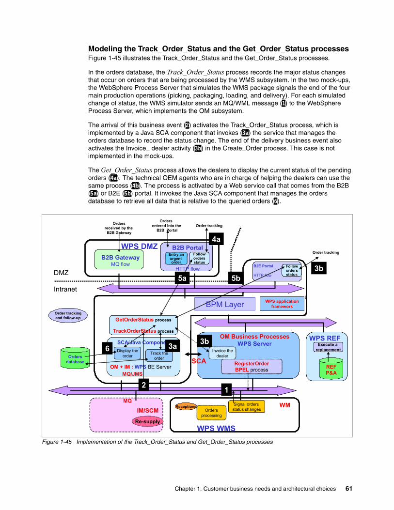
Modeling the Track_Order_Status and the Get_Order_Status processesFigure 1-45 illustrates the Track_Order_Status and the Get_Order_Status processes.
In the orders database, the Track_Order_Status process records the major status changes that occur on orders that are being processed by the WMS subsystem. In the two mock-ups, the WebSphere Process Server that simulates the WMS package signals the end of the four main production operations (picking, packaging, loading, and delivery). For each simulated change of status, the WMS simulator sends an MQ/WML message (1) to the WebSphere Process Server, which implements the OM subsystem.
The arrival of this business event (2) activates the Track_Order_Status process, which is implemented by a Java SCA component that invokes (3a) the service that manages the orders database to record the status change. The end of the delivery business event also activates the Invoice_ dealer activity (3b) in the Create_Order process. This case is not implemented in the mock-ups.
The Get_Order_Status process allows the dealers to display the current status of the pending orders (4a). The technical OEM agents who are in charge of helping the dealers can use the same process (4b). The process is activated by a Web service call that comes from the B2B (5a) or B2E (5b) portal. It invokes the Java SCA component that manages the orders database to retrieve all data that is relative to the queried orders (6).
Figure 1-45 Implementation of the Track_Order_Status and Get_Order_Status processes
BPM Layer
DMZ
Intranet
IM/SCM
WPS WMS
WPS REF
MQ/JMS
MQ
RegisterOrderBPEL process
GetOrderStatus process
TrackOrderStatus process
SCA
Ordersprocessing
OM Business ProcessesWPS Server
WPS DMZ
REFP&A
Execute a replacement
OM + IM : WPS BE Server
Ordersdatabase
WPS application framework
WM
Ordersreceived by the
B2B Gateway
Orders entered into the
B2B PortalOrder tracking
Followordersstatus
B2E Portal
HTTP flow
Order trackingB2B Gateway
MQ flow
B2B Portal
HTTP flow
Re-supply
Invoice thedealer
Signal orders status shanges
Track theorder
SCA/Java Components3a
Followordersstatus
5b
Receptions
Display theorder
Order trackingand follow-up
Entry anurgent order
12
3b3a
4a
3b5a 5b
6
Chapter 1. Customer business needs and architectural choices 61
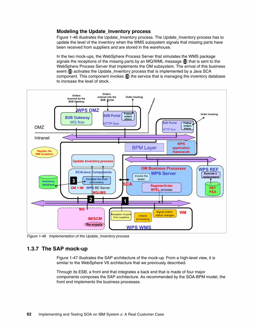
Modeling the Update_Inventory process Figure 1-46 illustrates the Update_Inventory process. The Update_Inventory process has to update the level of the inventory when the WMS subsystem signals that missing parts have been received from suppliers and are stored in the warehouse.
In the two mock-ups, the WebSphere Process Server that simulates the WMS package signals the receptions of the missing parts by an MQ/WML message (1) that is sent to the WebSphere Process Server that implements the OM subsystem. The arrival of this business event (2) activates the Update_Inventory process that is implemented by a Java SCA component. This component invokes (3) the service that is managing the inventory database to increase the level of stock.
Figure 1-46 Implementation of the Update_Inventory process
1.3.7 The SAP mock-up
Figure 1-47 illustrates the SAP architecture of the mock-up. From a high-level view, it is similar to the WebSphere V6 architecture that we previously described.
Through its ESB, a front end that integrates a back end that is made of four major components composes the SAP architecture. As recommended by the SOA-BPM model, the front end implements the business processes.
BPM Layer
DMZ
Intranet
IM/SCM
WPS WMS
WPS REF
MQ/JMS
MQ
RegisterOrderBPEL process
Update Inventory process
SCA
Ordersprocessing
OM Business ProcessesWPS Server
WPS DMZ
Register theWM receptions
REFP&A
Execute a replacement
OM + IM : WPS BE Server
Inventorydatabase
WPS application framework
WM
Ordersreceived by the
B2B Gateway
Orders entered into the
B2B PortalOrder tracking
Followordersstatus
B2E Portal
HTTP flow
Order trackingB2B Gateway
MQ flow
B2B Portal
HTTP flow
Re-supply
Invoice thedealer
Signal orders status changes
Increase the levelof inventory
SCA/Java Components
Followordersstatus
Reception of partsfrom suppliers
12
3
62 Implementing and Testing SOA on IBM System z: A Real Customer Case
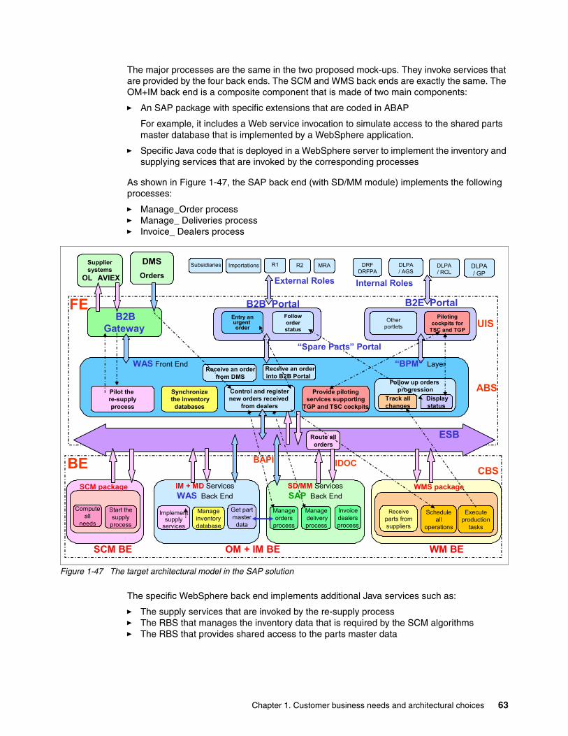
The major processes are the same in the two proposed mock-ups. They invoke services that are provided by the four back ends. The SCM and WMS back ends are exactly the same. The OM+IM back end is a composite component that is made of two main components:
� An SAP package with specific extensions that are coded in ABAP
For example, it includes a Web service invocation to simulate access to the shared parts master database that is implemented by a WebSphere application.
� Specific Java code that is deployed in a WebSphere server to implement the inventory and supplying services that are invoked by the corresponding processes
As shown in Figure 1-47, the SAP back end (with SD/MM module) implements the following processes:
� Manage_Order process� Manage_ Deliveries process� Invoice_ Dealers process
Figure 1-47 The target architectural model in the SAP solution
The specific WebSphere back end implements additional Java services such as:
� The supply services that are invoked by the re-supply process� The RBS that manages the inventory data that is required by the SCM algorithms � The RBS that provides shared access to the parts master data
DMSOrders
Suppliersystems
OL AVIEX
B2BGateway
DRFDRFPA
DLPA/ AGS
DLPA/ RCL
DLPA/ GP
ESB
Executeproduction
tasks
Scheduleall
operations
FE
BE
Implementsupply
services
CBS
Computeall
needs
Start thesupply
process
Receiveparts fromsuppliers
Manageinventorydatabase
IM + MD ServicesWAS Back End
Managedeliveryprocess
Follow up orders progression
Displaystatus
Track allchanges
WAS Front End
Pilot the re-supplyprocess
Provide pilotingservices supporting
TGP and TSC cockpits
SCM package WMS package
Synchronizethe inventory
databases
ABS
Pilotingcockpits for
TSC and TGP
Otherportlets
Route allorders
Subsidiaries Importations R1
B2B Portal
R2 MRA
Entry anurgent order
Followorderstatus
“Spare Parts” Portal
WM BESCM BE OM + IM BE
UIS
Manageorders
process
Control and registernew orders received
from dealers
Receive an orderfrom DMS
Receive an orderinto B2B Portal
B2E Portal
“BPM” Layer
External Roles Internal Roles
Get partmaster
data
Invoicedealersprocess
SD/MM ServicesSAP Back End
BAPI IDOC
Chapter 1. Customer business needs and architectural choices 63
The services or subprocesses that are implemented by SAP (SD/MM modules) are invoked from the BPM layer that is hosted in the front end through the ESB.
� The BAPI invocation (synchronous mode) requires the WebSphere SAP JCA connector.
� The IDOC message exchanges (asynchronous mode) require the WebSphere Business Integration Message Broker and the related SAP adapter.
These technical solutions are described in Connect WebSphere Service Oriented Middleware to SAP, SG24-7220.
Architectural model of the SAP solution and WebSphere V5 mock-upFigure 1-48 shows a high-level view of the SAP mock-up that is integrated with the WebSphere Version 5 technologies (WebSphere Application Server and WebSphere Business Integration Message Broker).
As suggested by its name, WebSphere Integration Server Version 5 provides all the integration functions that are requested by the SAP mock-up:
� The WebSphere Integration Server implements the four processes that build the prototype with Java code manually written. The previously described BPM technologies are not used in this prototype.
� The SAP server implements the standard SAP processes that manage orders and deliveries.
WebSphere Integration Server Version 5 hosts the BPM layer of the SOA-BPM model. The BPM model of the main processes that were previously described is still valid. However, these processes are implemented by Java components that are deployed as EJB or MDB.
These components invoke an SAP process (provided by the SDM/MM module) in synchronous mode by calling the related function as a standard or a specific BAPI. The synchronous BAPI invocations use the WebSphere SAP JCA connector.
The sending (or receiving) of asynchronous MQ/XML messages from WebSphere to (or from) SAP is done through the ESB and requires a conversion into or from IDOC, which is a specific EDI format used by SAP. The asynchronous IDOC interactions use the WebSphere Business Integration Message Broker and the related SAP adapter.
The SAP mock-up reuses the two WebSphere Process Server components that are developed for the WBI V6 prototype:
� The WebSphere Process Server that simulates the future WMS package (WPS WMS)� The WebSphere Process Server that simulates the future parts master data server (WPS
REF)
These two simulators have exactly the same functions in the two mock-ups. The WebSphere DMZ server simulates the reception of orders that are sent by the dealers.
This component is shared between the two mock-ups. It communicates with the WebSphere Integration Server using Web services, when it simulates the B2B portal, or using MQ/JMS, when it simulates the B2B gateway.
64 Implementing and Testing SOA on IBM System z: A Real Customer Case
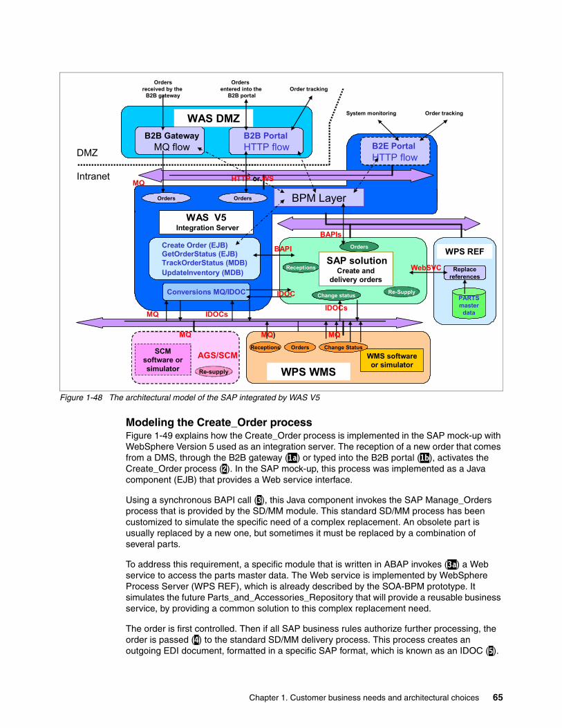
Figure 1-48 The architectural model of the SAP integrated by WAS V5
Modeling the Create_Order processFigure 1-49 explains how the Create_Order process is implemented in the SAP mock-up with WebSphere Version 5 used as an integration server. The reception of a new order that comes from a DMS, through the B2B gateway (1a) or typed into the B2B portal (1b), activates the Create_Order process (2). In the SAP mock-up, this process was implemented as a Java component (EJB) that provides a Web service interface.
Using a synchronous BAPI call (3), this Java component invokes the SAP Manage_Orders process that is provided by the SD/MM module. This standard SD/MM process has been customized to simulate the specific need of a complex replacement. An obsolete part is usually replaced by a new one, but sometimes it must be replaced by a combination of several parts.
To address this requirement, a specific module that is written in ABAP invokes (3a) a Web service to access the parts master data. The Web service is implemented by WebSphere Process Server (WPS REF), which is already described by the SOA-BPM prototype. It simulates the future Parts_and_Accessories_Repository that will provide a reusable business service, by providing a common solution to this complex replacement need.
The order is first controlled. Then if all SAP business rules authorize further processing, the order is passed (4) to the standard SD/MM delivery process. This process creates an outgoing EDI document, formatted in a specific SAP format, which is known as an IDOC (5).
Create Order (EJB)GetOrderStatus (EJB)TrackOrderStatus (MDB)UpdateInventory (MDB)
BAPIs
IDOCs
Orders
Re-Supply
Orders
Change status
Receptions
BPM Layer
DMZ
Intranet
SAP solutionCreate and
delivery orders
IDOCsMQ
Conversions MQ/IDOC
Orders
MQ HTTP or WS
WPS REF
PARTSmaster
data
Replacereferences
WebSVC
B2B PortalHTTP flow
B2B GatewayMQ flow
WAS DMZ
Ordersreceived by the
B2B gateway
Orders entered into the
B2B portal
Order tracking
Order tracking
B2E PortalHTTP flow
System monitoring
WAS V5Integration Server
AGS/SCMSCM software orsimulator Re-supply
MQ
WMS software or simulator
WPS WMS
Change StatusOrdersReceptions
MQMQ)
BAPI
IDOC
Chapter 1. Customer business needs and architectural choices 65
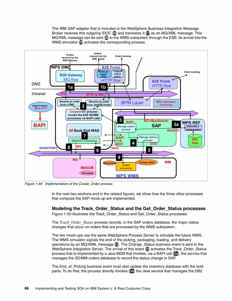
The WBI SAP adapter that is included in the WebSphere Business Integration Message Broker receives this outgoing IDOC (6) and translates it (7) as an MQ/XML message. This MQ/XML message can be sent (8) to the WMS subsystem through the ESB. Its arrival into the WMS simulator (9) activates the corresponding process.
Figure 1-49 Implementation of the Create_Order process
In the next two sections and in the related figures, we show how the three other processes that compose the SAP mock-up are implemented.
Modeling the Track_Order_Status and the Get_Order_Status processesFigure 1-50 illustrates the Track_Order_Status and Get_Order_Status processes.
The Track_Order_Status process records, in the SAP orders database, the major status changes that occur on orders that are processed by the WMS subsystem.
The two mock-ups use the same WebSphere Process Server to simulate the future WMS. The WMS simulator signals the end of the picking, packaging, loading, and delivery operations by an MQ/WML message (1). The Change_Status business event is sent to the WebSphere Integration Server. The arrival of this event (2) activates the Track_Order_Status process that is implemented by a Java MDB that invokes, via a BAPI call (3a), the service that manages the SD/MM orders database to record the status change in SAP.
The End_of_Picking business event must also update the inventory database with the sold parts. To do that, the process directly invokes (3b) the Java service that manages the DB2
BPM Layer
DMZ
Intranet
IM/SCM
WPS WMS
WPS REF
MQChange statusReceptions
CreateOrder processInvoke the SAP SD/MM
processes via BAPI calls
Ordersprocessing
2
WPS DMZ
Urgent orders: MQ & HTTP
REFP&A
Execute a replacement
HTTP or WSMQ
INVENTORY
WPS application framework
WM
Ordersreceived by the
B2B Gateway
Orders entered into the
B2B PortalOrder tracking
Entry anurgent order
Followordersstatus
B2E PortalHTTP flow
Order tracking
Receive an orderfrom a DMS
Receive an orderfrom theB2B Portal
B2B GatewayMQ flow
B2B Portal
HTTP flow
Re-supply
BAPI Manage ordersprocess
RC+Backbone:SAP 3a
BAPI
Manage deliveryprocess
IDOCMQ
JMSJMSMQ/IDOC conversions
IDOC
IM Back End WAS 7
IDOC
BAPI
WebSVC
1a 1b
2
3
456
7
8
9
3a
66 Implementing and Testing SOA on IBM System z: A Real Customer Case
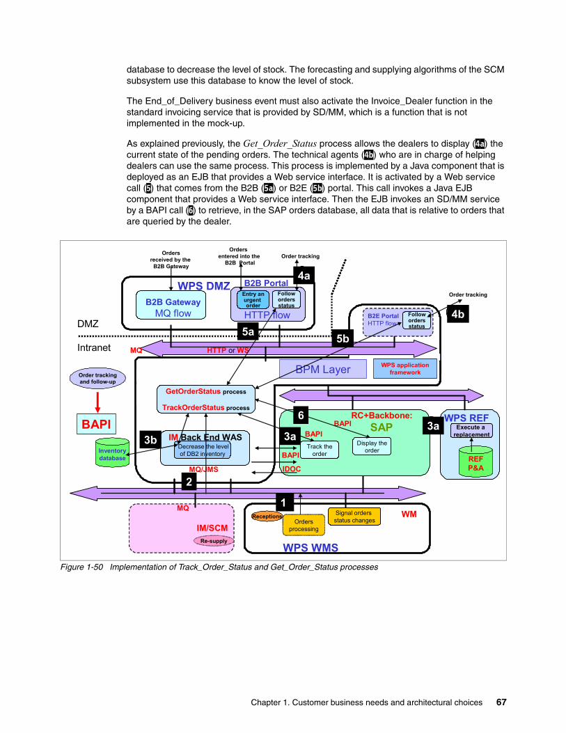
database to decrease the level of stock. The forecasting and supplying algorithms of the SCM subsystem use this database to know the level of stock.
The End_of_Delivery business event must also activate the Invoice_Dealer function in the standard invoicing service that is provided by SD/MM, which is a function that is not implemented in the mock-up.
As explained previously, the Get_Order_Status process allows the dealers to display (4a) the current state of the pending orders. The technical agents (4b) who are in charge of helping dealers can use the same process. This process is implemented by a Java component that is deployed as an EJB that provides a Web service interface. It is activated by a Web service call (5) that comes from the B2B (5a) or B2E (5b) portal. This call invokes a Java EJB component that provides a Web service interface. Then the EJB invokes an SD/MM service by a BAPI call (6) to retrieve, in the SAP orders database, all data that is relative to orders that are queried by the dealer.
Figure 1-50 Implementation of Track_Order_Status and Get_Order_Status processes
BPM Layer
DMZ
Intranet
IM/SCM
WPS WMS
WPS REF
MQ
WPS DMZ
REFP&A
Execute a replacement
HTTP or WS MQ
WPS application framework
WM
Ordersreceived by the
B2B Gateway
Orders entered into the
B2B PortalOrder tracking
Entry anurgent order
Followordersstatus
B2E PortalHTTP flow
Order trackingB2B Gateway
MQ flow
B2B Portal
HTTP flow
Re-supply
BAPIRC+Backbone:
SAP 3aBAPI
MQ/JMS IDOC
BAPITrack the
order
Display theorder
GetOrderStatus process
TrackOrderStatus process
Order trackingand follow-up
Followordersstatus
5b
4b
4a
BAPI
Ordersprocessing
Signal orders status changes
Receptions
Inventorydatabase
IM Back End WAS Decrease the levelof DB2 inventory
1
2
3a3b 3a
4b
4a
5a 5b
6
Chapter 1. Customer business needs and architectural choices 67
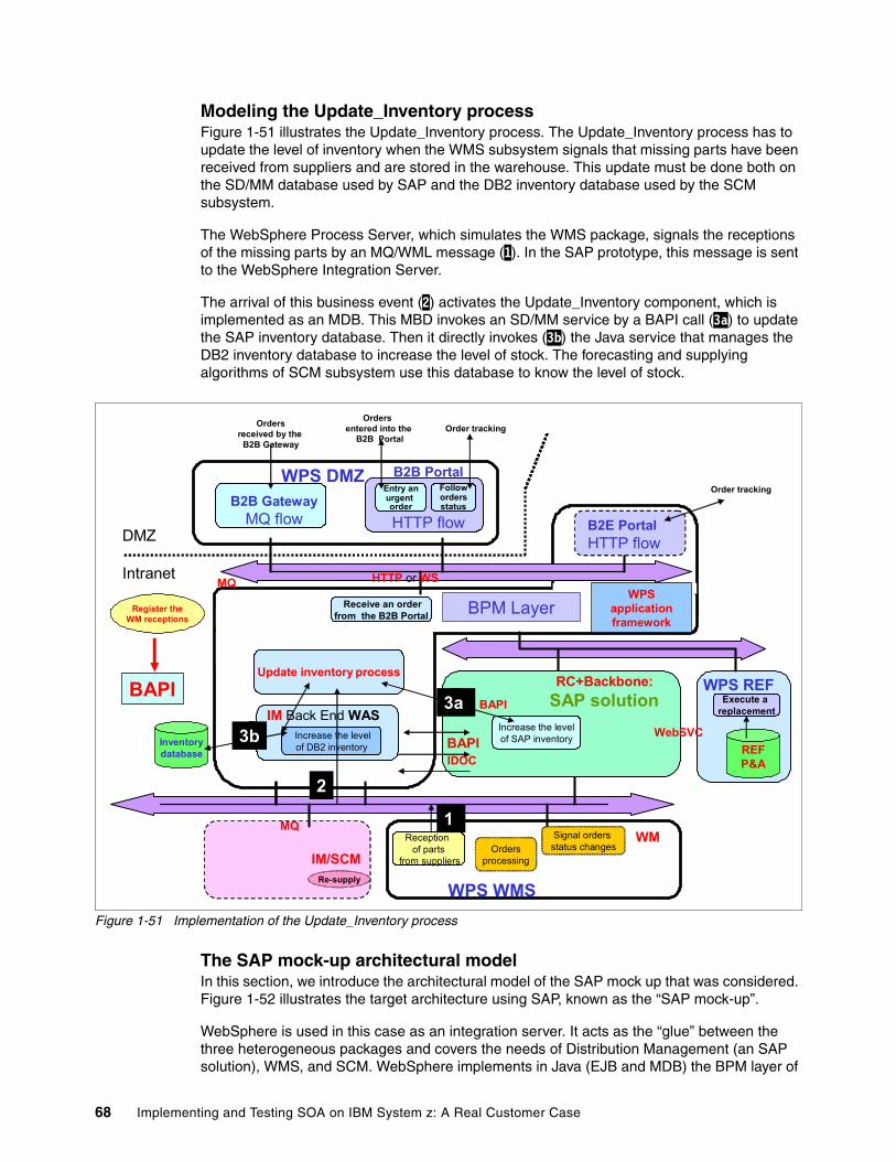
Modeling the Update_Inventory process Figure 1-51 illustrates the Update_Inventory process. The Update_Inventory process has to update the level of inventory when the WMS subsystem signals that missing parts have been received from suppliers and are stored in the warehouse. This update must be done both on the SD/MM database used by SAP and the DB2 inventory database used by the SCM subsystem.
The WebSphere Process Server, which simulates the WMS package, signals the receptions of the missing parts by an MQ/WML message (1). In the SAP prototype, this message is sent to the WebSphere Integration Server.
The arrival of this business event (2) activates the Update_Inventory component, which is implemented as an MDB. This MBD invokes an SD/MM service by a BAPI call (3a) to update the SAP inventory database. Then it directly invokes (3b) the Java service that manages the DB2 inventory database to increase the level of stock. The forecasting and supplying algorithms of SCM subsystem use this database to know the level of stock.
Figure 1-51 Implementation of the Update_Inventory process
The SAP mock-up architectural modelIn this section, we introduce the architectural model of the SAP mock up that was considered. Figure 1-52 illustrates the target architecture using SAP, known as the “SAP mock-up”.
WebSphere is used in this case as an integration server. It acts as the “glue” between the three heterogeneous packages and covers the needs of Distribution Management (an SAP solution), WMS, and SCM. WebSphere implements in Java (EJB and MDB) the BPM layer of
BPM Layer
DMZ
Intranet
IM/SCM
WPS WMS
WPS REF
MQ
WPS DMZ
REFP&A
Execute a replacement
HTTP or WS MQ
Inventorydatabase
WPS application framework
WM
Ordersreceived by the
B2B Gateway
Orders entered into the
B2B PortalOrder tracking
Entry anurgent order
Followordersstatus
B2E PortalHTTP flow
Order tracking
Receive an orderfrom the B2B Portal
B2B GatewayMQ flow
B2B Portal
HTTP flow
Re-supply
BAPI
Increase the levelof SAP inventory
RC+Backbone:SAP solution3a BAPI
IM Back End WAS
IDOC BAPI
Register theWM receptions
Ordersprocessing
Signal orders status changes
Reception of parts
from suppliers
Update inventory process
Increase the levelof DB2 inventory
3b
1
2
3a
3b WebSVC
68 Implementing and Testing SOA on IBM System z: A Real Customer Case
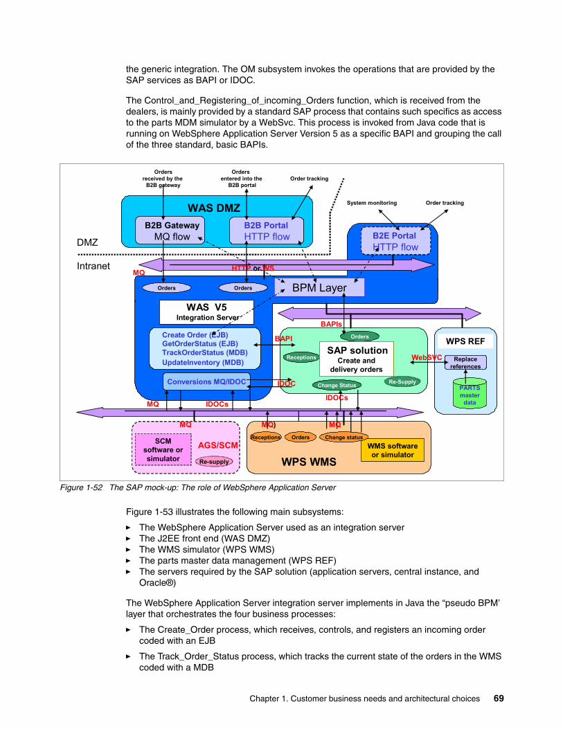
the generic integration. The OM subsystem invokes the operations that are provided by the SAP services as BAPI or IDOC.
The Control_and_Registering_of_incoming_Orders function, which is received from the dealers, is mainly provided by a standard SAP process that contains such specifics as access to the parts MDM simulator by a WebSvc. This process is invoked from Java code that is running on WebSphere Application Server Version 5 as a specific BAPI and grouping the call of the three standard, basic BAPIs.
Figure 1-52 The SAP mock-up: The role of WebSphere Application Server
Figure 1-53 illustrates the following main subsystems:
� The WebSphere Application Server used as an integration server � The J2EE front end (WAS DMZ)� The WMS simulator (WPS WMS)� The parts master data management (WPS REF)� The servers required by the SAP solution (application servers, central instance, and
Oracle®)
The WebSphere Application Server integration server implements in Java the “pseudo BPM’ layer that orchestrates the four business processes:
� The Create_Order process, which receives, controls, and registers an incoming order coded with an EJB
� The Track_Order_Status process, which tracks the current state of the orders in the WMS coded with a MDB
Create Order (EJB)GetOrderStatus (EJB)TrackOrderStatus (MDB)UpdateInventory (MDB)
BAPIs
IDOCs
Orders
Re-Supply
Orders
Change Status
Receptions
BPM Layer
DMZ
Intranet
SAP solutionCreate and
delivery orders
IDOCsMQ
Conversions MQ/IDOC
Orders
MQ HTTP or WS
WPS REF
PARTSmaster
data
Replacereferences
WebSVC
B2B PortalHTTP flow
B2B GatewayMQ flow
WAS DMZ
Ordersreceived by the
B2B gateway
Orders entered into the
B2B portal
Order tracking
Order tracking
B2E PortalHTTP flow
System monitoring
WAS V5Integration Server
AGS/SCMSCM software orsimulator Re-supply
MQ
WMS software or simulator
WPS WMS
Change statusOrdersReceptions
MQMQ)
BAPI
IDOC
Chapter 1. Customer business needs and architectural choices 69
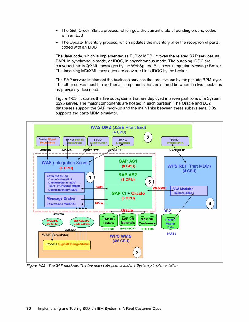
� The Get_Order_Status process, which gets the current state of pending orders, coded with an EJB
� The Update_Inventory process, which updates the inventory after the reception of parts, coded with an MDB
The Java code, which is implemented as EJB or MDB, invokes the related SAP services as BAPI, in synchronous mode, or IDOC, in asynchronous mode. The outgoing IDOC are converted into MQ/XML messages by the WebSphere Business Integration Message Broker. The incoming MQ/XML messages are converted into IDOC by the broker.
The SAP servers implement the business services that are invoked by the pseudo BPM layer. The other servers host the additional components that are shared between the two mock-ups as previously described.
Figure 1-53 illustrates the five subsystems that are deployed in seven partitions of a System p595 server. The major components are hosted in each partition. The Oracle and DB2 databases support the SAP mock-up and the main links between these subsystems. DB2 supports the parts MDM simulator.
Figure 1-53 The SAP mock-up: The five main subsystems and the System p implementation
WAS (Integration Server)(6 CPU)
JMS/MQ SOAP/HTTP
WPS REF (Part MDM)(4 CPU)
SAP DBMaterials
INVENTORY
SAP DBOrders
ORDERS
SAP DBCustomers
DEALERS
PARTSMasterData
PARTS
SOAP/HTTP
Process SignalChangeStatus
ServletSubmitOrder
ServletListOrders
ServletInvokeRefPA
Servlet SubmitOrderAsync
WAS DMZ (J2EE Front End)(4 CPU)
WMS Simulator WPS WMS(4/6 CPU)
JMS/MQ
JMS/MQ
SAP CI + Oracle(8 CPU)
Servlet SignalReceptions
Message BrokerConversions MQ/IDOC
Java modules• CreateOrders (EJB)• GetOrderStatus (EJB)• TrackOrderStatus (MDB)• UpdateInventory (MDB)
SAP AS1(8 CPU)
SAP AS2(8 CPU)
JMS/MQ SOAP/HTTP
SCA Modules• ReplaceOldRef
1
2
4
3
WebSVCBAPI
IDOC
Oracle DB2
5
MQ/XMLBO Order
MQ/XML:BO UpdateOrder
70 Implementing and Testing SOA on IBM System z: A Real Customer Case
1.4 Results and benefits
Through the setup of these mock-ups, the customer mainly wanted:
� To validate the architectural vision proposed for a business project:
– To prove the value of the generic integration model– To test the technical choices in terms of architecture, technologies, and tools– To build the foundation of the future system by implementing a methodology that is
founded on iterative development and reusable components
� For each scenario, SAP, specific WebSphere Process Server Version 6 application, or a mix of the two, to evaluate the required configuration, in terms of hardware and software, including:
– Measuring the response time and the consummation of resources– Defining the hardware and software configuration and estimating its cost
� To measure the complexity and estimate the cost of the future realization tasks, including:
– The development of the application code– The integration and interfaces – The migration scenarios
More generally speaking, the customer wanted to use this project to:
� Capitalize on a first successful SOA-BPM experience with the objective to widely share the acquired knowledge and the know-how required for large integration projects using:
– An SOA-BPM integration model
– WebSphere Version 6 technologies and tools (WebSphere Process Server, WebSphere Integration Developer, and WebSphere Business Modeling)
– A methodology using an iterative development and reusable business components
� Generalize this SOA approach with the objective to rationalize and modernize the major information systems written in a specific language (what we call OL in this chapter) that are no longer supported by application developers.
� Promote and generalize the SOA-BPM approach in order to realize:
– OL eradication in the critical or major IS– Modernization or renewal of value-added IS written in OL
� Share experiences and costs for developing synergies on:
– The SOA-BPM vision and the related generic integration model
– The WebSphere platform as an integration solution or as a framework for specific applications that provide a real value to the enterprise
For example, there are strong architectural and technical convergences between multiple customer projects.
� Measure the productivity gains provided by the new WebSphere V6 tools
Most importantly, the objective was to promote the SOA-BPM IBM approach as an efficient means to develop and modernize the strategic and major IS of this customer.
Chapter 1. Customer business needs and architectural choices 71

72 Implementing and Testing SOA on IBM System z: A Real Customer Case
Chapter 2. Application design
In this chapter, we discuss the following topics:
� The interfaces that need to be implemented between the application and the external business systems
� The subsystems that we used in our architecture
� The processes that need to be integrated to build the application
� The actual implementation on the System z platform
2
© Copyright IBM Corp. 2007. All rights reserved. 73
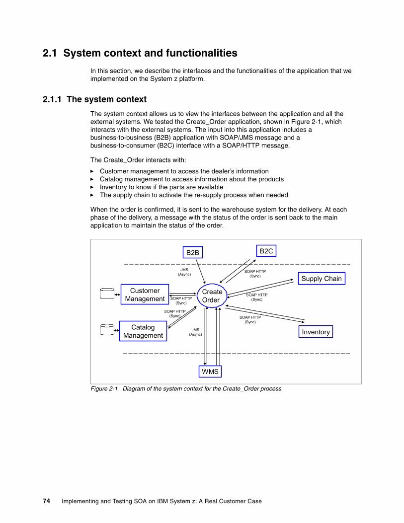
2.1 System context and functionalities
In this section, we describe the interfaces and the functionalities of the application that we implemented on the System z platform.
2.1.1 The system context
The system context allows us to view the interfaces between the application and all the external systems. We tested the Create_Order application, shown in Figure 2-1, which interacts with the external systems. The input into this application includes a business-to-business (B2B) application with SOAP/JMS message and a business-to-consumer (B2C) interface with a SOAP/HTTP message.
The Create_Order interacts with:
� Customer management to access the dealer’s information� Catalog management to access information about the products� Inventory to know if the parts are available� The supply chain to activate the re-supply process when needed
When the order is confirmed, it is sent to the warehouse system for the delivery. At each phase of the delivery, a message with the status of the order is sent back to the main application to maintain the status of the order.
Figure 2-1 Diagram of the system context for the Create_Order process
WMS
InventoryJMS(Async)
SOAP HTTP(Sync)
CatalogManagement
Supply ChainJMS
(Async)SOAP HTTP
(Sync)
B2B B2C
CustomerManagement SOAP HTTP
(Sync)
SOAP HTTP(Sync)
SOAP HTTP(Sync)
CreateOrder
74 Implementing and Testing SOA on IBM System z: A Real Customer Case
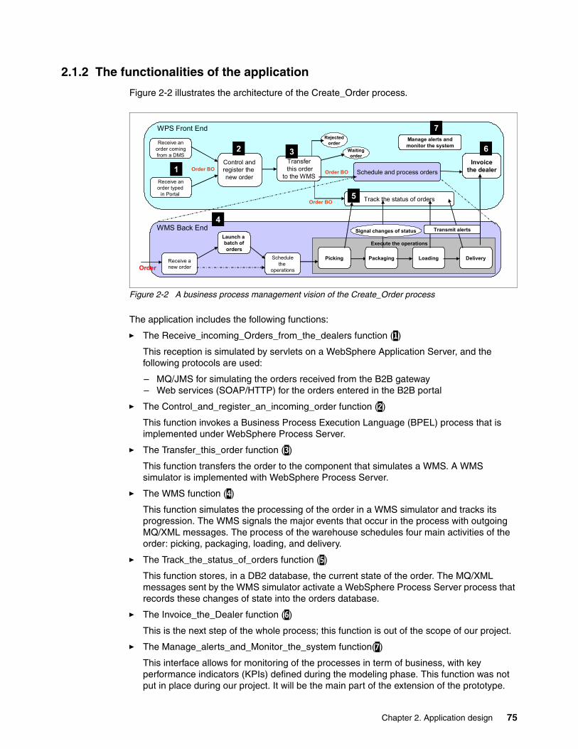
2.1.2 The functionalities of the application
Figure 2-2 illustrates the architecture of the Create_Order process.
Figure 2-2 A business process management vision of the Create_Order process
The application includes the following functions:
� The Receive_incoming_Orders_from_the_dealers function (1)
This reception is simulated by servlets on a WebSphere Application Server, and the following protocols are used:
– MQ/JMS for simulating the orders received from the B2B gateway– Web services (SOAP/HTTP) for the orders entered in the B2B portal
� The Control_and_register_an_incoming_order function (2)
This function invokes a Business Process Execution Language (BPEL) process that is implemented under WebSphere Process Server.
� The Transfer_this_order function (3)
This function transfers the order to the component that simulates a WMS. A WMS simulator is implemented with WebSphere Process Server.
� The WMS function (4)
This function simulates the processing of the order in a WMS simulator and tracks its progression. The WMS signals the major events that occur in the process with outgoing MQ/XML messages. The process of the warehouse schedules four main activities of the order: picking, packaging, loading, and delivery.
� The Track_the_status_of_orders function (5)
This function stores, in a DB2 database, the current state of the order. The MQ/XML messages sent by the WMS simulator activate a WebSphere Process Server process that records these changes of state into the orders database.
� The Invoice_the_Dealer function (6)
This is the next step of the whole process; this function is out of the scope of our project.
� The Manage_alerts_and_Monitor_the_system function(7)
This interface allows for monitoring of the processes in term of business, with key performance indicators (KPIs) defined during the modeling phase. This function was not put in place during our project. It will be the main part of the extension of the prototype.
Schedule and process orders
Receive anew order
Launch a batch oforders
Schedulethe
operationsOrder
Receive anorder comingfrom a DMS
Order BO
Rejectedorder
Waitingorder
Execute the operations
Packaging Loading DeliveryPicking
WMS Back End
Track the status of orders
Transferthis order
to the WMS
WPS Front End
Transmit alerts
Order BO
Receive anorder typed
in Portal
Manage alerts andmonitor the system
Signal changes of status
Order BO
Control andregister the new order
Invoicethe dealer1
2 3
4
5
6
7
Chapter 2. Application design 75
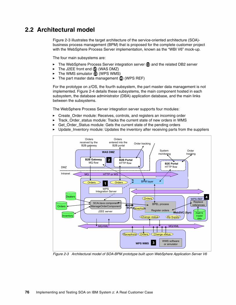
2.2 Architectural model
Figure 2-3 illustrates the target architecture of the service-oriented architecture (SOA)- business process management (BPM) that is proposed for the complete customer project with the WebSphere Process Server implementation, known as the “WBI V6” mock-up.
The four main subsystems are:
� The WebSphere Process Server integration server (1) and the related DB2 server� The J2EE front end (2) (WAS DMZ)� The WMS simulator (3) (WPS WMS)� The part master data management (4) (WPS REF)
For the prototype on z/OS, the fourth subsystem, the part master data management is not implemented. Figure 2-4 details these subsystems, the main component hosted in each subsystem, the database administrator (DBA) application database, and the main links between the subsystems.
The WebSphere Process Server integration server supports four modules:
� Create_Order module: Receives, controls, and registers an incoming order� Track_Order_status module: Tracks the current state of new orders in WMS� Get_Order_Status module: Gets the current state of the pending orders� Update_Inventory module: Updates the inventory after receiving parts from the suppliers
Figure 2-3 Architectural model of SOA-BPM prototype built upon WebSphere Application Server V6
Orders BPM layer
DMZ
Intranet
B2B PortalHTTP flow
B2B GatewayMQ flow
WAS DMZ
WMS software or simulatorWPS WMS
MQ/XML
Orders
MQ HTTP or WS
Change statusOrdersReceptions
Ordersreceived by the
B2B gateway
Orders entered into the
B2B portal
Ordertracking
Order tracking
WPS REF
BPEL process
Register ordersPARTSmaster
data
Replace references
MQ/XML
WebSVC (Syn)Re-Supply
Orders
Change status
Receptions
Inventory
Orders
Dealers
J2EE server
SCA/Java componentManageOrderComponent SCA
WPS Integration Server
B2E PortalHTTP flow
System monitoring
1
2
3
4
76 Implementing and Testing SOA on IBM System z: A Real Customer Case
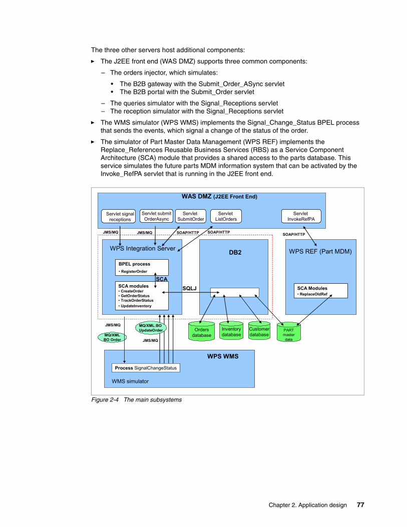
The three other servers host additional components:
� The J2EE front end (WAS DMZ) supports three common components:
– The orders injector, which simulates:
• The B2B gateway with the Submit_Order_ASync servlet• The B2B portal with the Submit_Order servlet
– The queries simulator with the Signal_Receptions servlet– The reception simulator with the Signal_Receptions servlet
� The WMS simulator (WPS WMS) implements the Signal_Change_Status BPEL process that sends the events, which signal a change of the status of the order.
� The simulator of Part Master Data Management (WPS REF) implements the Replace_References Reusable Business Services (RBS) as a Service Component Architecture (SCA) module that provides a shared access to the parts database. This service simulates the future parts MDM information system that can be activated by the Invoke_RefPA servlet that is running in the J2EE front end.
Figure 2-4 The main subsystems
WPS Integration Server
JMS/MQ SOAP/HTTP
WPS REF (Part MDM)
SOAP/HTTP
Process SignalChangeStatus
ServletSubmitOrder
ServletListOrders
ServletInvokeRefPA
Servlet submitOrderAsync
MQ/XMLBO Order
MQ/XML:BO UpdateOrder
WAS DMZ (J2EE Front End)
WPS WMS
JMS/MQ
JMS/MQ
DB2
Servlet signalreceptions
BPEL process• RegisterOrder
SCA modules• CreateOrder• GetOrderStatus• TrackOrderStatus• UpdateInventory
SCA Modules• ReplaceOldRef
Inventorydatabase
Ordersdatabase
Customerdatabase
PARTmasterdata
SQLJ
WMS simulator
JMS/MQ SOAP/HTTP
SCA
Chapter 2. Application design 77
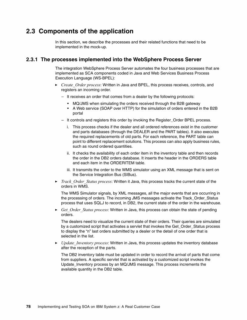
2.3 Components of the application
In this section, we describe the processes and their related functions that need to be implemented in the mock-up.
2.3.1 The processes implemented into the WebSphere Process Server
The integration WebSphere Process Server automates the four business processes that are implemented as SCA components coded in Java and Web Services Business Process Execution Language (WS-BPEL):
� Create_Order process: Written in Java and BPEL, this process receives, controls, and registers an incoming order.
– It receives an order that comes from a dealer by the following protocols:
• MQ/JMS when simulating the orders received through the B2B gateway• A Web service (SOAP over HTTP) for the simulation of orders entered in the B2B
portal
– It controls and registers this order by invoking the Register_Order BPEL process.
i. This process checks if the dealer and all ordered references exist in the customer and parts databases (through the DEALER and the PART tables). It also executes the required replacements of old parts. For each reference, the PART table can point to different replacement solutions. This process can also apply business rules, such as round ordered quantities.
ii. It checks the availability of each order item in the inventory table and then records the order in the DB2 orders database. It inserts the header in the ORDERS table and each item in the ORDERITEM table.
iii. It transmits the order to the WMS simulator using an XML message that is sent on the Service Integration Bus (SIBus).
� Track_Order_Status process: Written it Java, this process tracks the current state of the orders in WMS.
The WMS Simulator signals, by XML messages, all the major events that are occurring in the processing of orders. The incoming JMS messages activate the Track_Order_Status process that uses SQLJ to record, in DB2, the current state of the order in the warehouse.
� Get_Order_Status process: Written in Java, this process can obtain the state of pending orders.
The dealers need to visualize the current state of their orders. Their queries are simulated by a customized script that activates a servlet that invokes the Get_Order_Status process to display the “n” last orders submitted by a dealer or the detail of one order that is selected in the list.
� Update_Inventory process: Written in Java, this process updates the inventory database after the reception of the parts.
The DB2 inventory table must be updated in order to record the arrival of parts that come from suppliers. A specific servlet that is activated by a customized script invokes the Update_Inventory process by an MQ/JMS message. This process increments the available quantity in the DB2 table.
78 Implementing and Testing SOA on IBM System z: A Real Customer Case
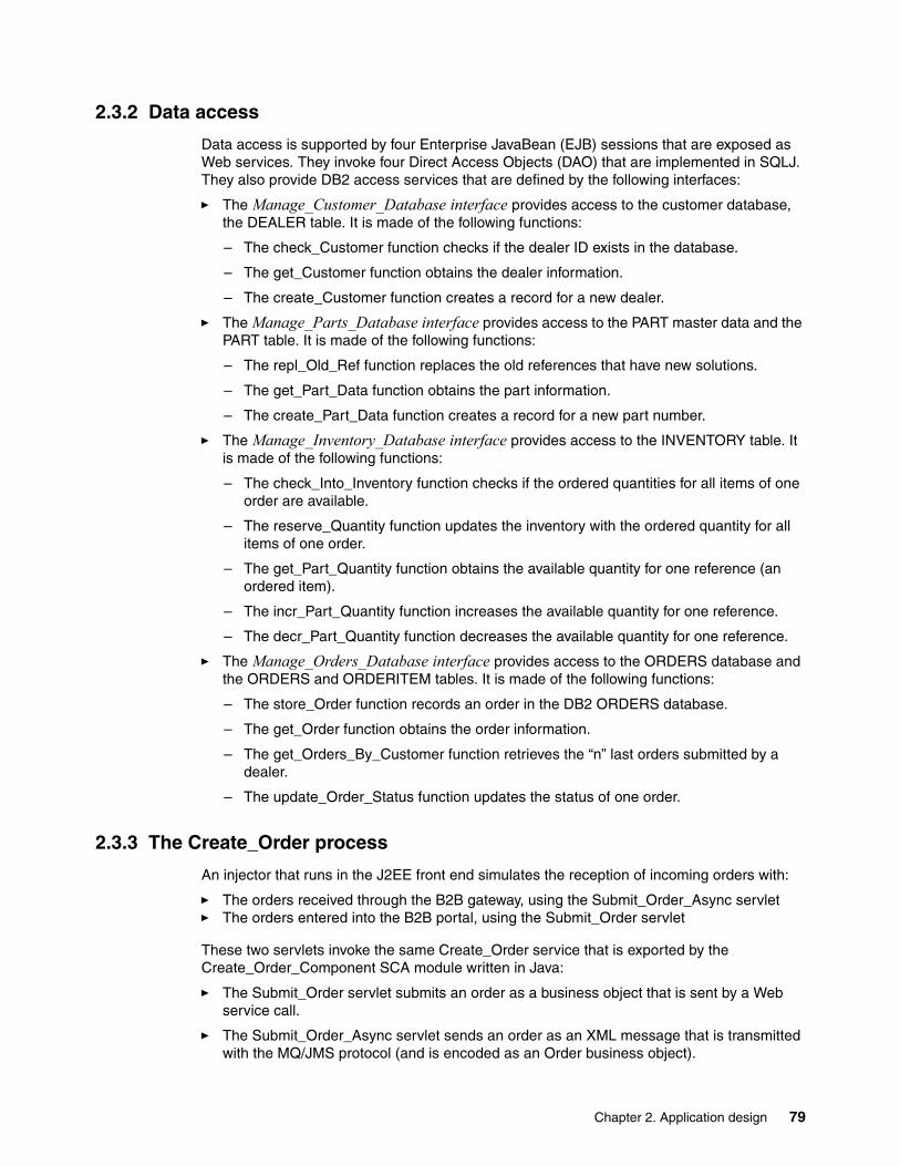
2.3.2 Data access
Data access is supported by four Enterprise JavaBean (EJB) sessions that are exposed as Web services. They invoke four Direct Access Objects (DAO) that are implemented in SQLJ. They also provide DB2 access services that are defined by the following interfaces:
� The Manage_Customer_Database interface provides access to the customer database, the DEALER table. It is made of the following functions:
– The check_Customer function checks if the dealer ID exists in the database.
– The get_Customer function obtains the dealer information.
– The create_Customer function creates a record for a new dealer.
� The Manage_Parts_Database interface provides access to the PART master data and the PART table. It is made of the following functions:
– The repl_Old_Ref function replaces the old references that have new solutions.
– The get_Part_Data function obtains the part information.
– The create_Part_Data function creates a record for a new part number.
� The Manage_Inventory_Database interface provides access to the INVENTORY table. It is made of the following functions:
– The check_Into_Inventory function checks if the ordered quantities for all items of one order are available.
– The reserve_Quantity function updates the inventory with the ordered quantity for all items of one order.
– The get_Part_Quantity function obtains the available quantity for one reference (an ordered item).
– The incr_Part_Quantity function increases the available quantity for one reference.
– The decr_Part_Quantity function decreases the available quantity for one reference.
� The Manage_Orders_Database interface provides access to the ORDERS database and the ORDERS and ORDERITEM tables. It is made of the following functions:
– The store_Order function records an order in the DB2 ORDERS database.
– The get_Order function obtains the order information.
– The get_Orders_By_Customer function retrieves the “n” last orders submitted by a dealer.
– The update_Order_Status function updates the status of one order.
2.3.3 The Create_Order process
An injector that runs in the J2EE front end simulates the reception of incoming orders with:
� The orders received through the B2B gateway, using the Submit_Order_Async servlet� The orders entered into the B2B portal, using the Submit_Order servlet
These two servlets invoke the same Create_Order service that is exported by the Create_Order_Component SCA module written in Java:
� The Submit_Order servlet submits an order as a business object that is sent by a Web service call.
� The Submit_Order_Async servlet sends an order as an XML message that is transmitted with the MQ/JMS protocol (and is encoded as an Order business object).
Chapter 2. Application design 79
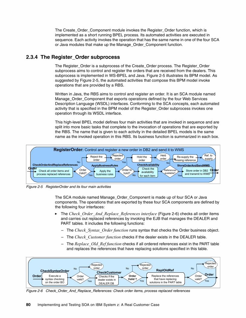
The Create_Order_Component module invokes the Register_Order function, which is implemented as a short running BPEL process. Its automated activities are executed in sequence. Each activity invokes the operation that has the same name in one of the four SCA or Java modules that make up the Manage_Order_Component function.
2.3.4 The Register_Order subprocess
The Register_Order is a subprocess of the Create_Order process. The Register_Order subprocess aims to control and register the orders that are received from the dealers. This subprocess is implemented in WS-BPEL and Java. Figure 2-5 illustrates its BPM model. As suggested by Figure 2-5, the automated activities that compose this BPM model invoke operations that are provided by a RBS.
Written in Java, the RBS aims to control and register an order. It is an SCA module named Manage_Order_Component that exports operations defined by the four Web Services Description Language (WSDL) interfaces. Conforming to the SCA concepts, each automated activity that is specified in the BPM model of the Register_Order subprocess invokes one operation through its WSDL interface.
This high-level BPEL model defines four main activities that are invoked in sequence and are split into more basic tasks that complete to the invocation of operations that are exported by the RBS. The name that is given to each activity in the detailed BPEL models is the same name as the invoked operation in this RBS. Its business function is summarized in each box.
Figure 2-5 RegisterOrder and its four main activities
The SCA module named Manage_Order_Component is made up of four SCA or Java components. The operations that are exported by these four SCA components are defined by the following four interfaces:
� The Check_Order_And_Replace_References interface (Figure 2-6) checks all order items and carries out replaced references by invoking the EJB that manages the DEALER and PART tables. It includes the following functions:
– The Check_Syntax_Order function runs syntax that checks the Order business object.
– The Check_Customer function checks if the dealer exists in the DEALER table.
– The Replace_Old_Ref function checks if all ordered references exist in the PART table and replaces the references that have replacing solutions specified in this table.
Figure 2-6 Check_Order_And_Replace_References: Check order items, process replaced references
Referencesavailable?
Yes
No
Re-supply themissing reference
Reject theorder
Rejectedorder
No
Apply thebusiness rules Yes
CheckOrderAndReplaceReferences CheckAvailabilityApplyBusinessRules StoreOrderAndSendWMSOrderValid?
Order tohold?
Hold theorder
Yes
Check all order items andprocess replaced references
Check theavailability
for each item
Store order in DB2 and transmit to WMS
RegisterOrder: Control and register a new order in DB2 and send it to WMS
OrderOrder
No
Heldorder
Ref. to supply
Replace the references that have replacing
solutions in the PART table
ReplOldRefOrderExecute a
syntax checkingon the order BO
CheckSyntaxOrderOrder Order
valid?Yes
No
OrderValid ?
Yes
No
CheckCustomerOrdervalid?
Yes
No
Checks if the dealer exists inDEALER DB
Rejectedorder
Rejectedorder
Rejectedorder
80 Implementing and Testing SOA on IBM System z: A Real Customer Case
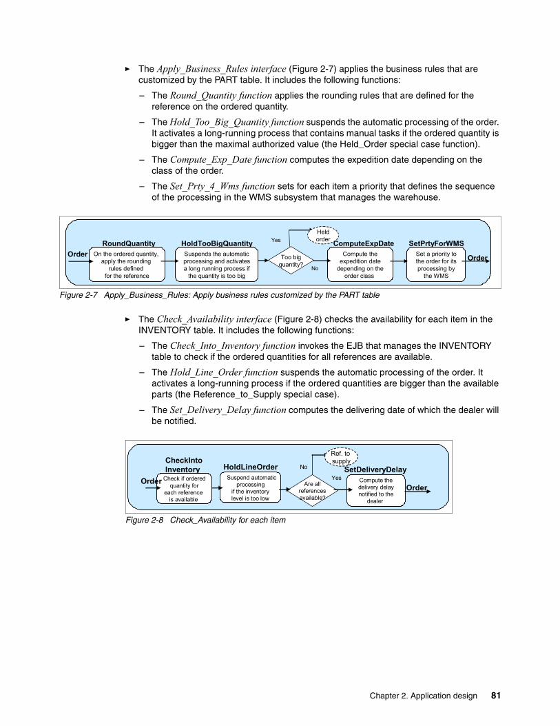
� The Apply_Business_Rules interface (Figure 2-7) applies the business rules that are customized by the PART table. It includes the following functions:
– The Round_Quantity function applies the rounding rules that are defined for the reference on the ordered quantity.
– The Hold_Too_Big_Quantity function suspends the automatic processing of the order. It activates a long-running process that contains manual tasks if the ordered quantity is bigger than the maximal authorized value (the Held_Order special case function).
– The Compute_Exp_Date function computes the expedition date depending on the class of the order.
– The Set_Prty_4_Wms function sets for each item a priority that defines the sequence of the processing in the WMS subsystem that manages the warehouse.
Figure 2-7 Apply_Business_Rules: Apply business rules customized by the PART table
� The Check_Availability interface (Figure 2-8) checks the availability for each item in the INVENTORY table. It includes the following functions:
– The Check_Into_Inventory function invokes the EJB that manages the INVENTORY table to check if the ordered quantities for all references are available.
– The Hold_Line_Order function suspends the automatic processing of the order. It activates a long-running process if the ordered quantities are bigger than the available parts (the Reference_to_Supply special case).
– The Set_Delivery_Delay function computes the delivering date of which the dealer will be notified.
Figure 2-8 Check_Availability for each item
On the ordered quantity, apply the rounding
rules defined for the reference
Suspends the automaticprocessing and activates a long running process if
the quantity is too big
Compute theexpedition date
depending on theorder class
RoundQuantityOrder Too big
quantity?No
YesHoldTooBigQuantity ComputeExpDate
OrderSet a priority tothe order for itsprocessing by
the WMS
SetPrtyForWMSHeldorder
Suspend automaticprocessing
if the inventorylevel is too low
Compute thedelivery delaynotified to the
dealer
Are allreferencesavailable?
Yes
NoHoldLineOrder SetDeliveryDelayCheck if ordered
quantity foreach reference
is available
CheckIntoInventory
OrderOrder
Ref. to supply
Chapter 2. Application design 81
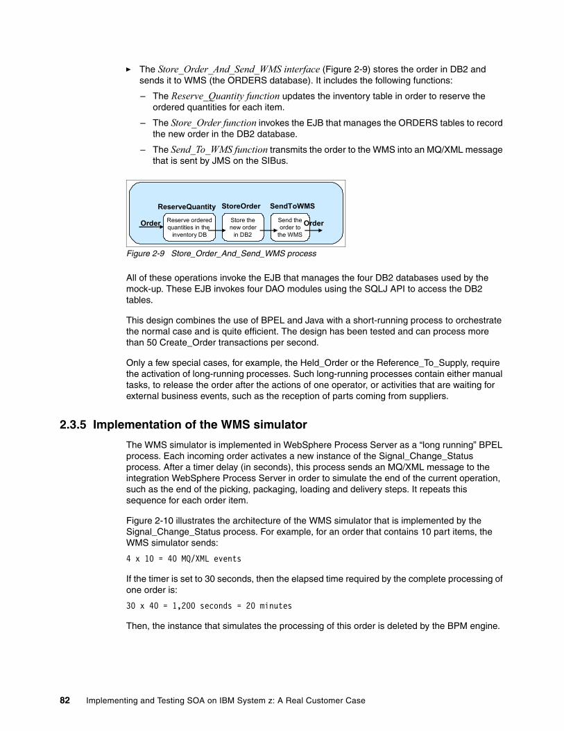
� The Store_Order_And_Send_WMS interface (Figure 2-9) stores the order in DB2 and sends it to WMS (the ORDERS database). It includes the following functions:
– The Reserve_Quantity function updates the inventory table in order to reserve the ordered quantities for each item.
– The Store_Order function invokes the EJB that manages the ORDERS tables to record the new order in the DB2 database.
– The Send_To_WMS function transmits the order to the WMS into an MQ/XML message that is sent by JMS on the SIBus.
Figure 2-9 Store_Order_And_Send_WMS process
All of these operations invoke the EJB that manages the four DB2 databases used by the mock-up. These EJB invokes four DAO modules using the SQLJ API to access the DB2 tables.
This design combines the use of BPEL and Java with a short-running process to orchestrate the normal case and is quite efficient. The design has been tested and can process more than 50 Create_Order transactions per second.
Only a few special cases, for example, the Held_Order or the Reference_To_Supply, require the activation of long-running processes. Such long-running processes contain either manual tasks, to release the order after the actions of one operator, or activities that are waiting for external business events, such as the reception of parts coming from suppliers.
2.3.5 Implementation of the WMS simulator
The WMS simulator is implemented in WebSphere Process Server as a “long running” BPEL process. Each incoming order activates a new instance of the Signal_Change_Status process. After a timer delay (in seconds), this process sends an MQ/XML message to the integration WebSphere Process Server in order to simulate the end of the current operation, such as the end of the picking, packaging, loading and delivery steps. It repeats this sequence for each order item.
Figure 2-10 illustrates the architecture of the WMS simulator that is implemented by the Signal_Change_Status process. For example, for an order that contains 10 part items, the WMS simulator sends:
4 x 10 = 40 MQ/XML events
If the timer is set to 30 seconds, then the elapsed time required by the complete processing of one order is:
30 x 40 = 1,200 seconds = 20 minutes
Then, the instance that simulates the processing of this order is deleted by the BPM engine.
ReserveQuantity
Reserve orderedquantities in the
inventory DB
Order Store thenew order
in DB2
Send theorder to
the WMS
StoreOrder SendToWMS
Order
82 Implementing and Testing SOA on IBM System z: A Real Customer Case
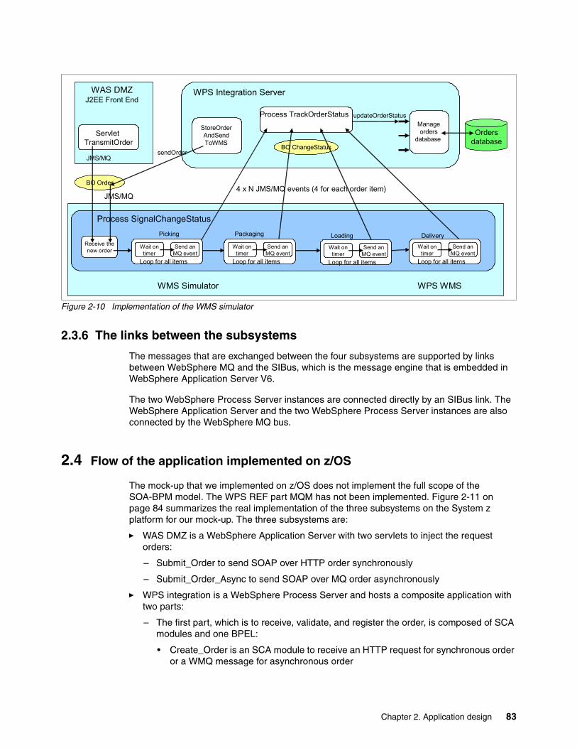
Figure 2-10 Implementation of the WMS simulator
2.3.6 The links between the subsystems
The messages that are exchanged between the four subsystems are supported by links between WebSphere MQ and the SIBus, which is the message engine that is embedded in WebSphere Application Server V6.
The two WebSphere Process Server instances are connected directly by an SIBus link. The WebSphere Application Server and the two WebSphere Process Server instances are also connected by the WebSphere MQ bus.
2.4 Flow of the application implemented on z/OS
The mock-up that we implemented on z/OS does not implement the full scope of the SOA-BPM model. The WPS REF part MQM has not been implemented. Figure 2-11 on page 84 summarizes the real implementation of the three subsystems on the System z platform for our mock-up. The three subsystems are:
� WAS DMZ is a WebSphere Application Server with two servlets to inject the request orders:
– Submit_Order to send SOAP over HTTP order synchronously
– Submit_Order_Async to send SOAP over MQ order asynchronously
� WPS integration is a WebSphere Process Server and hosts a composite application with two parts:
– The first part, which is to receive, validate, and register the order, is composed of SCA modules and one BPEL:
• Create_Order is an SCA module to receive an HTTP request for synchronous order or a WMQ message for asynchronous order
Ordersdatabase
BO Order
Manageorders
database
StoreOrderAndSendToWMS
Receive thenew order
WPS WMS
Process TrackOrderStatus
BO ChangeStatus
Packaging Loading DeliveryPicking
updateOrderStatus
sendOrder
JMS/MQ4 x N JMS/MQ events (4 for each order item)
JMS/MQ
ServletTransmitOrder
WAS DMZJ2EE Front End
WPS Integration Server
Process SignalChangeStatus
Wait ontimer
Send anMQ event
Loop for all items
WMS Simulator
Wait ontimer
Send anMQ event
Loop for all items
Wait ontimer
Send anMQ event
Loop for all items
Wait ontimer
Send anMQ event
Loop for all items
Chapter 2. Application design 83
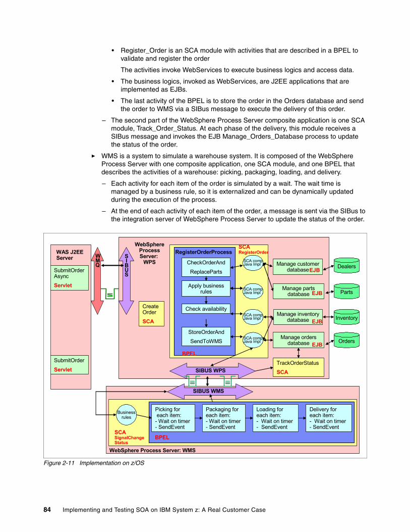
• Register_Order is an SCA module with activities that are described in a BPEL to validate and register the order
The activities invoke WebServices to execute business logics and access data.
• The business logics, invoked as WebServices, are J2EE applications that are implemented as EJBs.
• The last activity of the BPEL is to store the order in the Orders database and send the order to WMS via a SIBus message to execute the delivery of this order.
– The second part of the WebSphere Process Server composite application is one SCA module, Track_Order_Status. At each phase of the delivery, this module receives a SIBus message and invokes the EJB Manage_Orders_Database process to update the status of the order.
� WMS is a system to simulate a warehouse system. It is composed of the WebSphere Process Server with one composite application, one SCA module, and one BPEL that describes the activities of a warehouse: picking, packaging, loading, and delivery.
– Each activity for each item of the order is simulated by a wait. The wait time is managed by a business rule, so it is externalized and can be dynamically updated during the execution of the process.
– At the end of each activity of each item of the order, a message is sent via the SIBus to the integration server of WebSphere Process Server to update the status of the order.
Figure 2-11 Implementation on z/OS
WebSphereProcessServer:
WPS
CreateOrder
SCA
BPEL
RegisterOrderProcess
CheckOrderAnd
ReplaceParts
Apply business rules
Check availability
StoreOrderAnd
SendToWMS
Manage customerdatabase
Manage partsdatabase
Manage inventorydatabase
Manage ordersdatabase
EJB
EJB
EJB
EJB
SCA compJava Impl
SCA compJava Impl
SCA compJava Impl
SCA compJava Impl
SCARegisterOrder
WebSphere Process Server: WMS
Dealers
Parts
Inventory
Orders
WAS J2EEServer
SubmitOrderAsync
Servlet
SubmitOrder
Servlet
WMQ
SIBUS
SIBUS WPS
SIBUS WMS
TrackOrderStatus
SCA
SCASignalChangeStatus
BPEL
Businessrules
Packaging for each item:- Wait on timer - SendEvent
Loading for each item:- Wait on timer - SendEvent
Delivery for each item:- Wait on timer - SendEvent
Picking foreach item:
- Wait on timer - SendEvent
84 Implementing and Testing SOA on IBM System z: A Real Customer Case
Chapter 3. Implementation of the WebSphere Process Server V6 mock-up
In this chapter, we present an overview of the “WBI V6” mock-up that was implemented in the IBM European Design Center. The objective is to provide an overall solution that demonstrates the utilization of the WebSphere Process Server to host the Register_Order subprocess. This subprocess is responsible for the management of incoming orders for spare parts that are received from the dealers. In this publication, it is the Order Management (OM) subsystem.
The mock-up should include the process server itself as well as the main components with which it interacts to fulfill an order. For our mock-up, these components are:
� The component that encapsulates the business logic� The production Warehouse Management System (WMS)� A system that generates the order, either synchronously or asynchronously
In this chapter, we also describe the z/OS configuration that has been established. We emphasize two specific and important points:
� The WebSphere Process Server DB2 configuration� The interconnection between the different systems
3
© Copyright IBM Corp. 2007. All rights reserved. 85
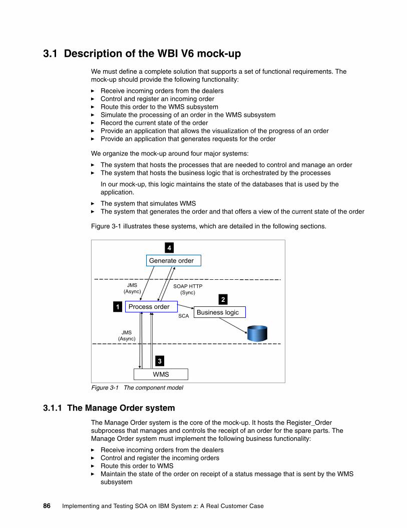
3.1 Description of the WBI V6 mock-up
We must define a complete solution that supports a set of functional requirements. The mock-up should provide the following functionality:
� Receive incoming orders from the dealers� Control and register an incoming order� Route this order to the WMS subsystem� Simulate the processing of an order in the WMS subsystem� Record the current state of the order� Provide an application that allows the visualization of the progress of an order� Provide an application that generates requests for the order
We organize the mock-up around four major systems:
� The system that hosts the processes that are needed to control and manage an order� The system that hosts the business logic that is orchestrated by the processes
In our mock-up, this logic maintains the state of the databases that is used by the application.
� The system that simulates WMS� The system that generates the order and that offers a view of the current state of the order
Figure 3-1 illustrates these systems, which are detailed in the following sections.
Figure 3-1 The component model
3.1.1 The Manage Order system
The Manage Order system is the core of the mock-up. It hosts the Register_Order subprocess that manages and controls the receipt of an order for the spare parts. The Manage Order system must implement the following business functionality:
� Receive incoming orders from the dealers� Control and register the incoming orders� Route this order to WMS� Maintain the state of the order on receipt of a status message that is sent by the WMS
subsystem
WMS
Process order
JMS(Async)
SOAP HTTP(Sync)
JMS(Async)
Generate order
Business logicSCA
12
3
4
86 Implementing and Testing SOA on IBM System z: A Real Customer Case
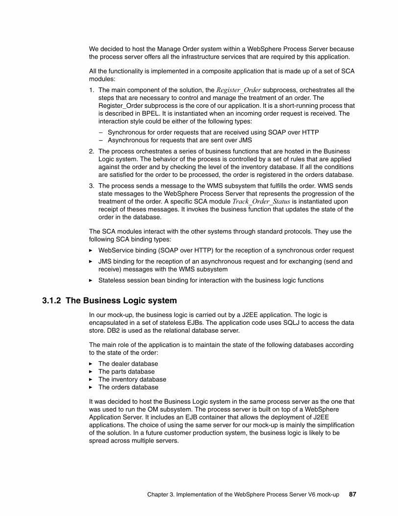
We decided to host the Manage Order system within a WebSphere Process Server because the process server offers all the infrastructure services that are required by this application.
All the functionality is implemented in a composite application that is made up of a set of SCA modules:
1. The main component of the solution, the Register_Order subprocess, orchestrates all the steps that are necessary to control and manage the treatment of an order. The Register_Order subprocess is the core of our application. It is a short-running process that is described in BPEL. It is instantiated when an incoming order request is received. The interaction style could be either of the following types:
– Synchronous for order requests that are received using SOAP over HTTP – Asynchronous for requests that are sent over JMS
2. The process orchestrates a series of business functions that are hosted in the Business Logic system. The behavior of the process is controlled by a set of rules that are applied against the order and by checking the level of the inventory database. If all the conditions are satisfied for the order to be processed, the order is registered in the orders database.
3. The process sends a message to the WMS subsystem that fulfills the order. WMS sends state messages to the WebSphere Process Server that represents the progression of the treatment of the order. A specific SCA module Track_Order_Status is instantiated upon receipt of theses messages. It invokes the business function that updates the state of the order in the database.
The SCA modules interact with the other systems through standard protocols. They use the following SCA binding types:
� WebService binding (SOAP over HTTP) for the reception of a synchronous order request
� JMS binding for the reception of an asynchronous request and for exchanging (send and receive) messages with the WMS subsystem
� Stateless session bean binding for interaction with the business logic functions
3.1.2 The Business Logic system
In our mock-up, the business logic is carried out by a J2EE application. The logic is encapsulated in a set of stateless EJBs. The application code uses SQLJ to access the data store. DB2 is used as the relational database server.
The main role of the application is to maintain the state of the following databases according to the state of the order:
� The dealer database� The parts database� The inventory database� The orders database
It was decided to host the Business Logic system in the same process server as the one that was used to run the OM subsystem. The process server is built on top of a WebSphere Application Server. It includes an EJB container that allows the deployment of J2EE applications. The choice of using the same server for our mock-up is mainly the simplification of the solution. In a future customer production system, the business logic is likely to be spread across multiple servers.
Chapter 3. Implementation of the WebSphere Process Server V6 mock-up 87
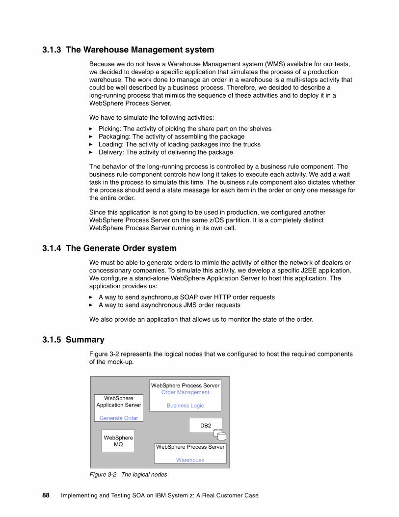
3.1.3 The Warehouse Management system
Because we do not have a Warehouse Management system (WMS) available for our tests, we decided to develop a specific application that simulates the process of a production warehouse. The work done to manage an order in a warehouse is a multi-steps activity that could be well described by a business process. Therefore, we decided to describe a long-running process that mimics the sequence of these activities and to deploy it in a WebSphere Process Server.
We have to simulate the following activities:
� Picking: The activity of picking the share part on the shelves� Packaging: The activity of assembling the package� Loading: The activity of loading packages into the trucks� Delivery: The activity of delivering the package
The behavior of the long-running process is controlled by a business rule component. The business rule component controls how long it takes to execute each activity. We add a wait task in the process to simulate this time. The business rule component also dictates whether the process should send a state message for each item in the order or only one message for the entire order.
Since this application is not going to be used in production, we configured another WebSphere Process Server on the same z/OS partition. It is a completely distinct WebSphere Process Server running in its own cell.
3.1.4 The Generate Order system
We must be able to generate orders to mimic the activity of either the network of dealers or concessionary companies. To simulate this activity, we develop a specific J2EE application. We configure a stand-alone WebSphere Application Server to host this application. The application provides us:
� A way to send synchronous SOAP over HTTP order requests� A way to send asynchronous JMS order requests
We also provide an application that allows us to monitor the state of the order.
3.1.5 Summary
Figure 3-2 represents the logical nodes that we configured to host the required components of the mock-up.
Figure 3-2 The logical nodes
WebSphereApplication Server
Generate Order
WebSphere Process ServerOrder Management
Business Logic
WebSphere Process Server
Warehouse
WebSphereMQ
DB2
88 Implementing and Testing SOA on IBM System z: A Real Customer Case
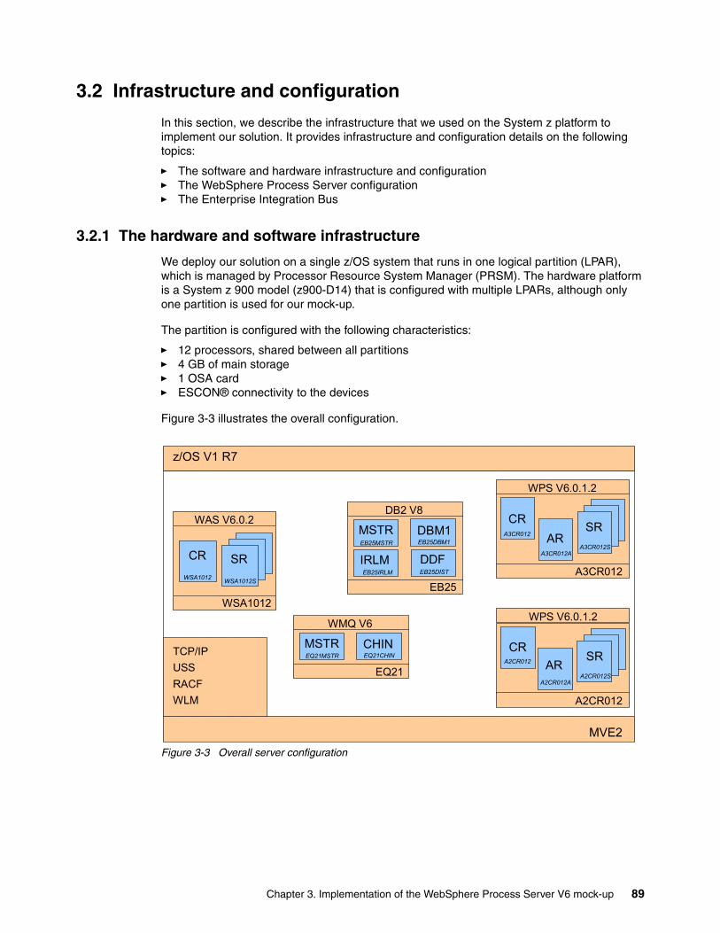
3.2 Infrastructure and configuration
In this section, we describe the infrastructure that we used on the System z platform to implement our solution. It provides infrastructure and configuration details on the following topics:
� The software and hardware infrastructure and configuration� The WebSphere Process Server configuration� The Enterprise Integration Bus
3.2.1 The hardware and software infrastructure
We deploy our solution on a single z/OS system that runs in one logical partition (LPAR), which is managed by Processor Resource System Manager (PRSM). The hardware platform is a System z 900 model (z900-D14) that is configured with multiple LPARs, although only one partition is used for our mock-up.
The partition is configured with the following characteristics:
� 12 processors, shared between all partitions� 4 GB of main storage� 1 OSA card� ESCON® connectivity to the devices
Figure 3-3 illustrates the overall configuration.
Figure 3-3 Overall server configuration
z/OS V1 R7
MVE2
WAS V6.0.2
WSA1012
CR SR
WMQ V6
EQ21
MSTR CHIN
WPS V6.0.1.2
A3CR012
CR SRDB2 V8
EB25
MSTR DBM1 AR
WPS V6.0.1.2
A2CR012
CRSR
AR
IRLM DDFA3CR012S
A3CR012A
A3CR012
A2CR012SA2CR012A
A2CR012
EB25MSTR EB25DBM1
EB25IRLM EB25DIST
EQ21MSTR EQ21CHIN
WSA1012 WSA1012S
TCP/IPUSSRACFWLM
Chapter 3. Implementation of the WebSphere Process Server V6 mock-up 89
Based on the logical nodes that are needed to run the overall solution, we installed the following subsystem on the partition:
� A DB2 Version 8 subsystem, which we used as both the enterprise database server and to configure the WebSphere Process Server
� A WebSphere MQ Version 6 subsystem, which we used as the JMS provider within the WebSphere Application Server
� A WebSphere Application Server Version 6.0.2, which we used to generate the order requests
� Two WebSphere Process Server Version 6.0.1, which we used to host the different business processes
Figure 3-4 illustrates the global infrastructure configuration.
Figure 3-4 Hardware infrastructure
3.2.2 The WebSphere Process Server configuration
In this section, we describe how the WebSphere Process Server was configured for our tests. In particular, we describe the DB2 aspects of the configuration.
The basic configuration
In this section, we provide information about how we installed and configured WebSphere Process Server on z/OS. We do not describe the entire installation process, but rather focus on the specific details of our configuration. Refer to z/OS Getting Started: WebSphere Process Server and WebSphere Enterprise Service Bus V6, SG24-7378, which provides the details about the entire installation.
LPAR 1Hardware12 CPS
4 GB Memory
Z900
PR/SM
MVE2Software
z/OS V1R7WAS V6.0.2WPS V6.0.1
WMQ V6DB2 V8
Restriction: The mock-up was implemented with a preliminary version of WebSphere Process Server Version 6 on z/OS. Some of our remarks may be different from the current version.
90 Implementing and Testing SOA on IBM System z: A Real Customer Case
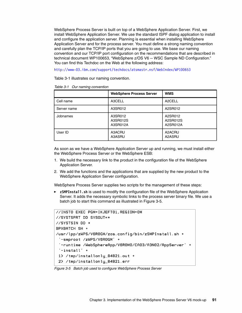
WebSphere Process Server is built on top of a WebSphere Application Server. First, we install WebSphere Application Server. We use the standard ISPF dialog application to install and configure the application server. Planning is essential when installing WebSphere Application Server and for the process server. You must define a strong naming convention and carefully plan the TCP/IP ports that you are going to use. We base our naming convention and our TCP/IP port configuration on the recommendations that are described in technical document WP100653, “WebSphere z/OS V6 -- WSC Sample ND Configuration.” You can find this Techdoc on the Web at the following address:
http://www-03.ibm.com/support/techdocs/atsmastr.nsf/WebIndex/WP100653
Table 3-1 illustrates our naming convention.
Table 3-1 Our naming convention
As soon as we have a WebSphere Application Server up and running, we must install either the WebSphere Process Server or the WebSphere ESB:
1. We build the necessary link to the product in the configuration file of the WebSphere Application Server.
2. We add the functions and the applications that are supplied by the new product to the WebSphere Application Server configuration.
WebSphere Process Server supplies two scripts for the management of these steps:
� zSMPInstall.sh is used to modify the configuration file of the WebSphere Application Server. It adds the necessary symbolic links to the process server binary file. We use a batch job to start this command as illustrated in Figure 3-5.
Figure 3-5 Batch job used to configure WebSphere Process Server
WebSphere Process Server WMS
Cell name A3CELL A2CELL
Server name A3SR012 A2SR012
Jobnames A3SR012A3SR012SA3SR012A
A2SR012A2SR012SA2SR012A
User ID A3ACRUA3ASRU
A2ACRUA2ASRU
Chapter 3. Implementation of the WebSphere Process Server V6 mock-up 91
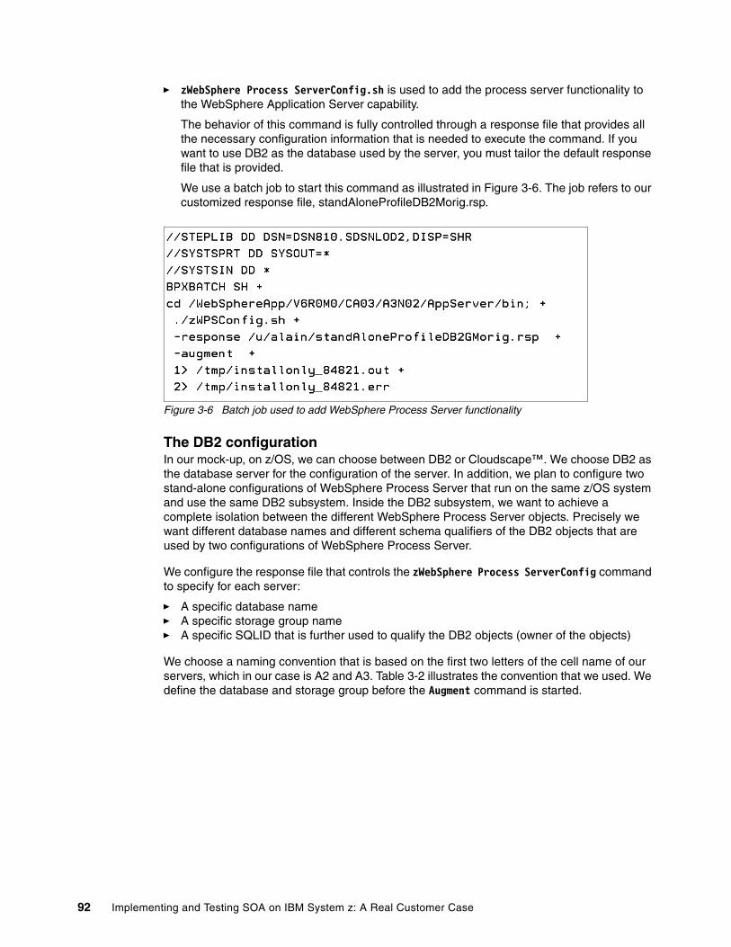
� zWebSphere Process ServerConfig.sh is used to add the process server functionality to the WebSphere Application Server capability.
The behavior of this command is fully controlled through a response file that provides all the necessary configuration information that is needed to execute the command. If you want to use DB2 as the database used by the server, you must tailor the default response file that is provided.
We use a batch job to start this command as illustrated in Figure 3-6. The job refers to our customized response file, standAloneProfileDB2Morig.rsp.
Figure 3-6 Batch job used to add WebSphere Process Server functionality
The DB2 configurationIn our mock-up, on z/OS, we can choose between DB2 or Cloudscape™. We choose DB2 as the database server for the configuration of the server. In addition, we plan to configure two stand-alone configurations of WebSphere Process Server that run on the same z/OS system and use the same DB2 subsystem. Inside the DB2 subsystem, we want to achieve a complete isolation between the different WebSphere Process Server objects. Precisely we want different database names and different schema qualifiers of the DB2 objects that are used by two configurations of WebSphere Process Server.
We configure the response file that controls the zWebSphere Process ServerConfig command to specify for each server:
� A specific database name� A specific storage group name� A specific SQLID that is further used to qualify the DB2 objects (owner of the objects)
We choose a naming convention that is based on the first two letters of the cell name of our servers, which in our case is A2 and A3. Table 3-2 illustrates the convention that we used. We define the database and storage group before the Augment command is started.
92 Implementing and Testing SOA on IBM System z: A Real Customer Case
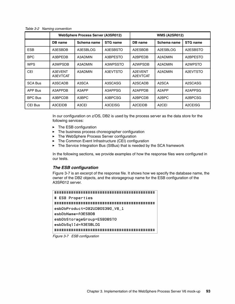
Table 3-2 Naming convention
In our configuration on z/OS, DB2 is used by the process server as the data store for the following services:
� The ESB configuration� The business process choreographer configuration� The WebSphere Process Server configuration� The Common Event Infrastructure (CEI) configuration� The Service Integration Bus (SIBus) that is needed by the SCA framework
In the following sections, we provide examples of how the response files were configured in our tests.
The ESB configurationFigure 3-7 is an excerpt of the response file. It shows how we specify the database name, the owner of the DB2 objects, and the storagegroup name for the ESB configuration of the A3SR012 server.
Figure 3-7 ESB configuration
WebSphere Process Server (A3SR012) WMS (A2SR012)
DB name Schema name STG name DB name Schema name STG name
ESB A3ESBDB A3ESBLOG A3ESBSTO A2ESBDB A2ESBLOG A2ESBSTO
BPC A3BPEDB A3ADMIN A3BPESTO A2BPEDB A2ADMIN A2BPESTO
WPS A3WPSDB A3ADMIN A3WPSSTO A2WPSDB A2ADMIN A2WPSTO
CEI A3EVENTA3EVTCAT
A3ADMIN A3EVTSTO A2EVENTA2EVTCAT
A2ADMIN A2EVTSTO
SCA Bus A3SCADB A3SCA A3SCASG A2SCADB A2SCA A2SCASG
APP Bus A3APPDB A3APP A3APPSG A2APPDB A2APP A2APPSG
BPC Bus A3BPCDB A3BPC A3BPCSG A2BPCDB A2BPC A2BPCSG
CEI Bus A3CEIDB A3CEI A3CEISG A2CEIDB A2CEI A2CEISG
Chapter 3. Implementation of the WebSphere Process Server V6 mock-up 93
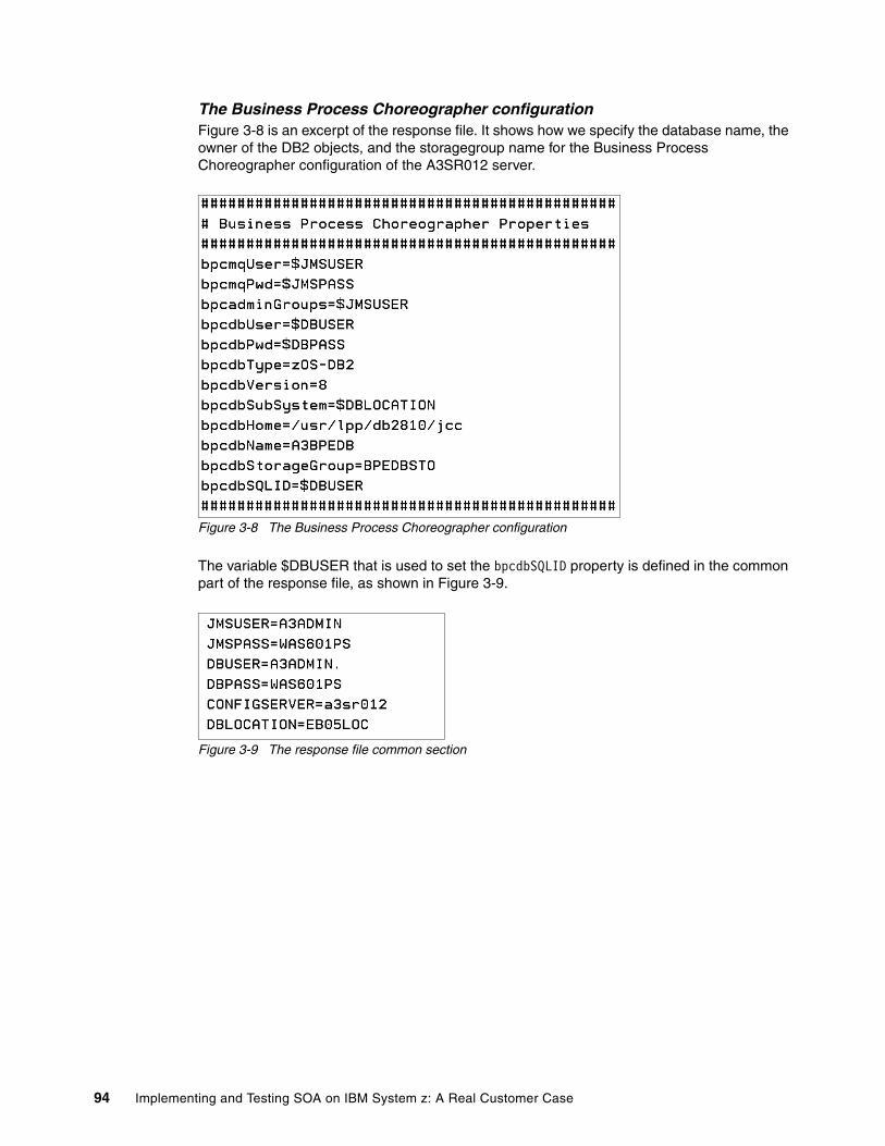
The Business Process Choreographer configurationFigure 3-8 is an excerpt of the response file. It shows how we specify the database name, the owner of the DB2 objects, and the storagegroup name for the Business Process Choreographer configuration of the A3SR012 server.
Figure 3-8 The Business Process Choreographer configuration
The variable $DBUSER that is used to set the bpcdbSQLID property is defined in the common part of the response file, as shown in Figure 3-9.
Figure 3-9 The response file common section
94 Implementing and Testing SOA on IBM System z: A Real Customer Case
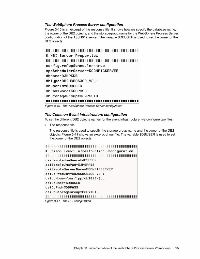
The WebSphere Process Server configurationFigure 3-10 is an excerpt of the response file. It shows how we specify the database name, the owner of the DB2 objects, and the storagegroup name for the WebSphere Process Server configuration of the A3SR012 server. The variable $DBUSER is used to set the owner of the DB2 objects.
Figure 3-10 The WebSphere Process Server configuration
The Common Event Infrastructure configurationTo set the different DB2 objects names for the event infrastructure, we configure two files:
� The response file
The response file is used to specify the storage group name and the owner of the DB2 objects. Figure 3-11 shows an excerpt of our file. The variable $DBUSER is used to set the owner of the DB2 objects.
Figure 3-11 The CEI configuration
Chapter 3. Implementation of the WebSphere Process Server V6 mock-up 95
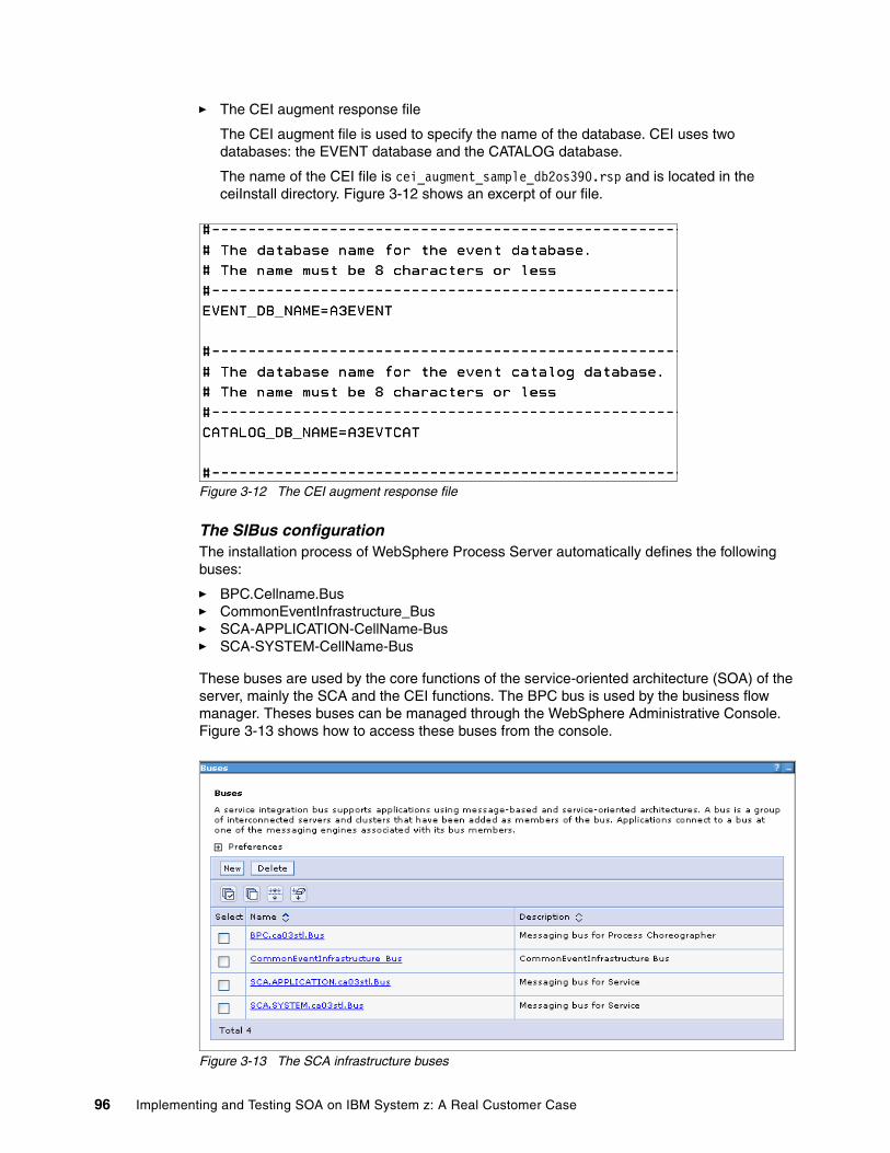
� The CEI augment response file
The CEI augment file is used to specify the name of the database. CEI uses two databases: the EVENT database and the CATALOG database.
The name of the CEI file is cei_augment_sample_db2os390.rsp and is located in the ceiInstall directory. Figure 3-12 shows an excerpt of our file.
Figure 3-12 The CEI augment response file
The SIBus configurationThe installation process of WebSphere Process Server automatically defines the following buses:
� BPC.Cellname.Bus� CommonEventInfrastructure_Bus� SCA-APPLICATION-CellName-Bus� SCA-SYSTEM-CellName-Bus
These buses are used by the core functions of the service-oriented architecture (SOA) of the server, mainly the SCA and the CEI functions. The BPC bus is used by the business flow manager. Theses buses can be managed through the WebSphere Administrative Console. Figure 3-13 shows how to access these buses from the console.
Figure 3-13 The SCA infrastructure buses
96 Implementing and Testing SOA on IBM System z: A Real Customer Case
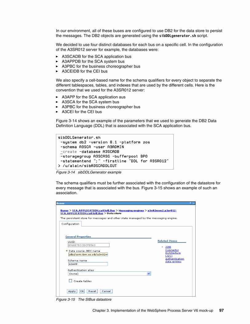
In our environment, all of these buses are configured to use DB2 for the data store to persist the messages. The DB2 objects are generated using the sibDDLgenerator.sh script.
We decided to use four distinct databases for each bus on a specific cell. In the configuration of the A3SR012 server for example, the databases were:
� A3SCADB for the SCA application bus� A3APPDB for the SCA system bus� A3PBC for the business choreographer bus� A3CEIDB for the CEI bus
We also specify a cell-based name for the schema qualifiers for every object to separate the different tablespaces, tables, and indexes that are used by the different cells. Here is the convention that we used for the A3SR012 server:
� A3APP for the SCA application aus� A3SCA for the SCA system bus� A3PBC for the business choreographer bus� A3CEI for the CEI bus
Figure 3-14 shows an example of the parameters that we used to generate the DB2 Data Definition Language (DDL) that is associated with the SCA application bus.
Figure 3-14 sibDDLGenerator example
The schema qualifiers must be further associated with the configuration of the datastore for every message that is associated with the bus. Figure 3-15 shows an example of such an association.
Figure 3-15 The SIBus datastore
Chapter 3. Implementation of the WebSphere Process Server V6 mock-up 97
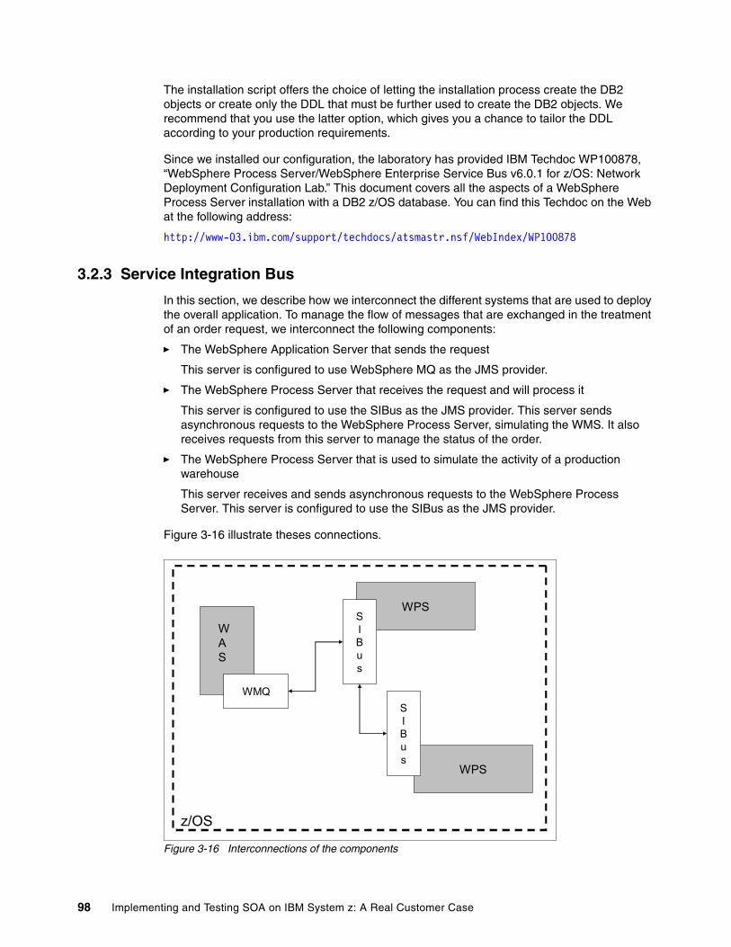
The installation script offers the choice of letting the installation process create the DB2 objects or create only the DDL that must be further used to create the DB2 objects. We recommend that you use the latter option, which gives you a chance to tailor the DDL according to your production requirements.
Since we installed our configuration, the laboratory has provided IBM Techdoc WP100878, “WebSphere Process Server/WebSphere Enterprise Service Bus v6.0.1 for z/OS: Network Deployment Configuration Lab.” This document covers all the aspects of a WebSphere Process Server installation with a DB2 z/OS database. You can find this Techdoc on the Web at the following address:
http://www-03.ibm.com/support/techdocs/atsmastr.nsf/WebIndex/WP100878
3.2.3 Service Integration Bus
In this section, we describe how we interconnect the different systems that are used to deploy the overall application. To manage the flow of messages that are exchanged in the treatment of an order request, we interconnect the following components:
� The WebSphere Application Server that sends the request
This server is configured to use WebSphere MQ as the JMS provider.
� The WebSphere Process Server that receives the request and will process it
This server is configured to use the SIBus as the JMS provider. This server sends asynchronous requests to the WebSphere Process Server, simulating the WMS. It also receives requests from this server to manage the status of the order.
� The WebSphere Process Server that is used to simulate the activity of a production warehouse
This server receives and sends asynchronous requests to the WebSphere Process Server. This server is configured to use the SIBus as the JMS provider.
Figure 3-16 illustrate theses connections.
Figure 3-16 Interconnections of the components
z/OS
WAS
WMQ
WPS
WPS
SIBus
SIBus
98 Implementing and Testing SOA on IBM System z: A Real Customer Case
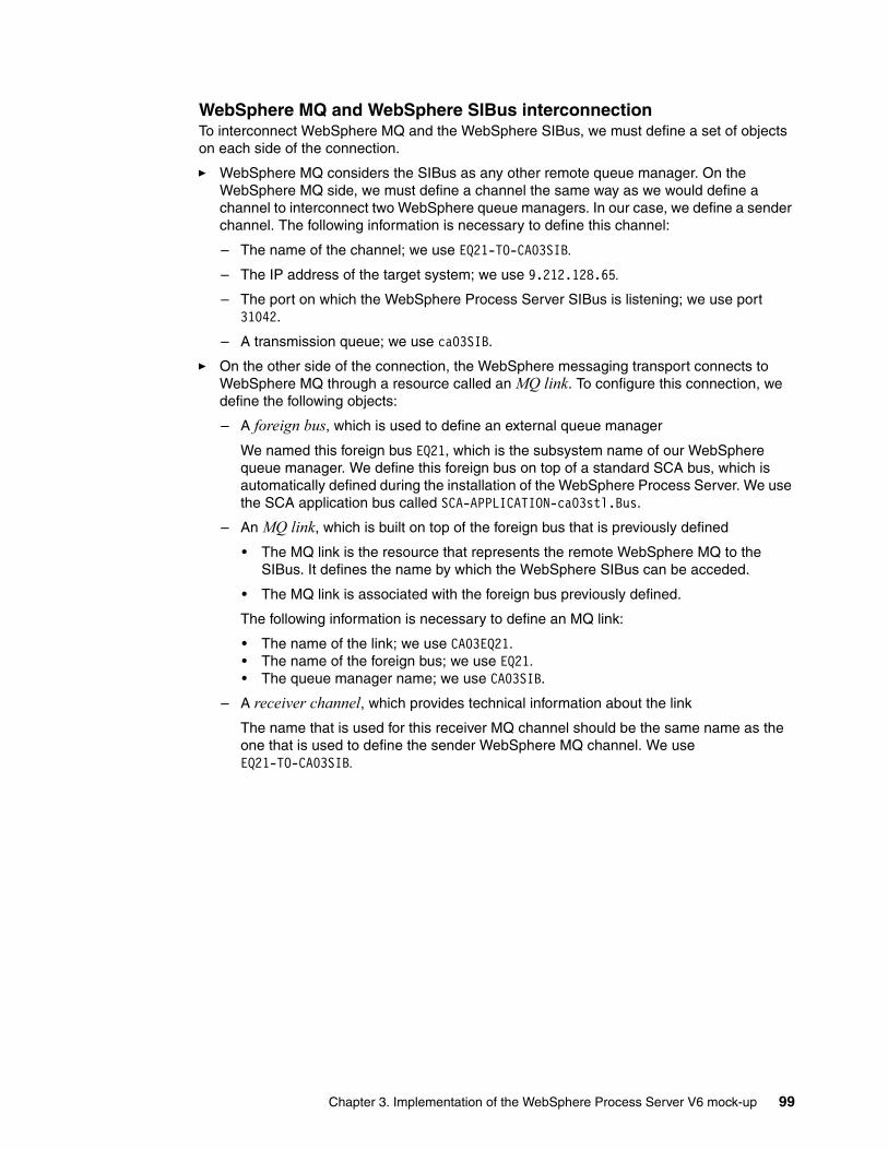
WebSphere MQ and WebSphere SIBus interconnectionTo interconnect WebSphere MQ and the WebSphere SIBus, we must define a set of objects on each side of the connection.
� WebSphere MQ considers the SIBus as any other remote queue manager. On the WebSphere MQ side, we must define a channel the same way as we would define a channel to interconnect two WebSphere queue managers. In our case, we define a sender channel. The following information is necessary to define this channel:
– The name of the channel; we use EQ21-TO-CA03SIB.– The IP address of the target system; we use 9.212.128.65.– The port on which the WebSphere Process Server SIBus is listening; we use port
31042.
– A transmission queue; we use ca03SIB.
� On the other side of the connection, the WebSphere messaging transport connects to WebSphere MQ through a resource called an MQ link. To configure this connection, we define the following objects:
– A foreign bus, which is used to define an external queue manager
We named this foreign bus EQ21, which is the subsystem name of our WebSphere queue manager. We define this foreign bus on top of a standard SCA bus, which is automatically defined during the installation of the WebSphere Process Server. We use the SCA application bus called SCA-APPLICATION-ca03stl.Bus.
– An MQ link, which is built on top of the foreign bus that is previously defined
• The MQ link is the resource that represents the remote WebSphere MQ to the SIBus. It defines the name by which the WebSphere SIBus can be acceded.
• The MQ link is associated with the foreign bus previously defined.
The following information is necessary to define an MQ link:
• The name of the link; we use CA03EQ21.• The name of the foreign bus; we use EQ21.• The queue manager name; we use CA03SIB.
– A receiver channel, which provides technical information about the link
The name that is used for this receiver MQ channel should be the same name as the one that is used to define the sender WebSphere MQ channel. We use EQ21-TO-CA03SIB.
Chapter 3. Implementation of the WebSphere Process Server V6 mock-up 99
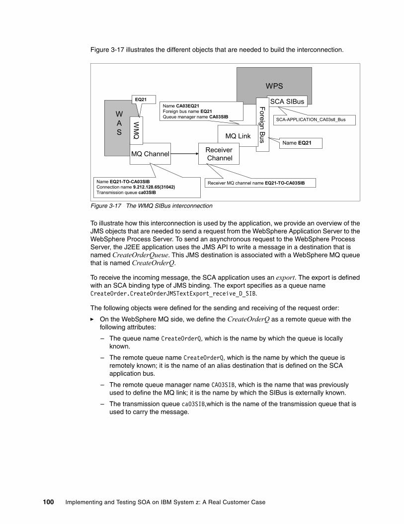
Figure 3-17 illustrates the different objects that are needed to build the interconnection.
Figure 3-17 The WMQ SIBus interconnection
To illustrate how this interconnection is used by the application, we provide an overview of the JMS objects that are needed to send a request from the WebSphere Application Server to the WebSphere Process Server. To send an asynchronous request to the WebSphere Process Server, the J2EE application uses the JMS API to write a message in a destination that is named CreateOrderQueue. This JMS destination is associated with a WebSphere MQ queue that is named CreateOrderQ.
To receive the incoming message, the SCA application uses an export. The export is defined with an SCA binding type of JMS binding. The export specifies as a queue name CreateOrder.CreateOrderJMSTextExport_receive_D_SIB.
The following objects were defined for the sending and receiving of the request order:
� On the WebSphere MQ side, we define the CreateOrderQ as a remote queue with the following attributes:
– The queue name CreateOrderQ, which is the name by which the queue is locally known.
– The remote queue name CreateOrderQ, which is the name by which the queue is remotely known; it is the name of an alias destination that is defined on the SCA application bus.
– The remote queue manager name CAO3SIB, which is the name that was previously used to define the MQ link; it is the name by which the SIBus is externally known.
– The transmission queue ca03SIB,which is the name of the transmission queue that is used to carry the message.
WAS
MQ Channel
WPS
SCA SIBusForeign BusMQ Link
ReceiverChannel
Name EQ21-TO-CA03SIBConnection name 9.212.128.65(31042)Transmission queue ca03SIB
Receiver MQ channel name EQ21-TO-CA03SIB
Name CA03EQ21Foreign bus name EQ21Queue manager name CA03SIB
Name EQ21
SCA-APPLICATION_CA03stl_BusWM
Q
EQ21
100 Implementing and Testing SOA on IBM System z: A Real Customer Case
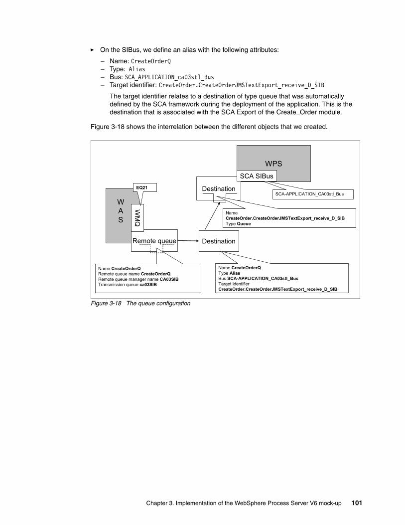
� On the SIBus, we define an alias with the following attributes:
– Name: CreateOrderQ– Type: Alias– Bus: SCA_APPLICATION_ca03stl_Bus– Target identifier: CreateOrder.CreateOrderJMSTextExport_receive_D_SIB
The target identifier relates to a destination of type queue that was automatically defined by the SCA framework during the deployment of the application. This is the destination that is associated with the SCA Export of the Create_Order module.
Figure 3-18 shows the interrelation between the different objects that we created.
Figure 3-18 The queue configuration
WAS
Remote queue
WPS
Destination
Name CreateOrderQRemote queue name CreateOrderQRemote queue manager name CA03SIBTransmission queue ca03SIB
SCA-APPLICATION_CA03stl_Bus
WM
Q
EQ21
Name CreateOrderQType AliasBus SCA-APPLICATION_CA03stl_BusTarget identifier CreateOrder.CreateOrderJMSTextExport_receive_D_SIB
Destination
Name CreateOrder.CreateOrderJMSTextExport_receive_D_SIBType Queue
SCA SIBus
Chapter 3. Implementation of the WebSphere Process Server V6 mock-up 101
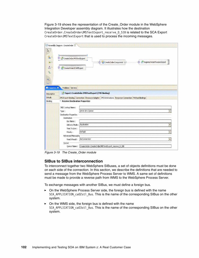
Figure 3-19 shows the representation of the Create_Order module in the WebSphere Integration Developer assembly diagram. It illustrates how the destination CreateOrder.CreateOrderJMSTextExport_receive_D_SIB is related to the SCA Export CreateOrderJMSTextExport that is used to process the incoming messages.
Figure 3-19 The Create_Order module
SIBus to SIBus interconnectionTo interconnect together two WebSphere SIBuses, a set of objects definitions must be done on each side of the connection. In this section, we describe the definitions that are needed to send a message from the WebSphere Process Server to WMS. A same set of definitions must be made to provide a reverse path from WMS to the WebSphere Process Server.
To exchange messages with another SIBus, we must define a foreign bus.
� On the WebSphere Process Server side, the foreign bus is defined with the name SCA_APPLICATION_ca02stl_Bus. This is the name of the corresponding SIBus on the other system.
� On the WMS side, the foreign bus is defined with the name SCA_APPLICATION_ca03stl_Bus. This is the name of the corresponding SIBus on the other system.
102 Implementing and Testing SOA on IBM System z: A Real Customer Case
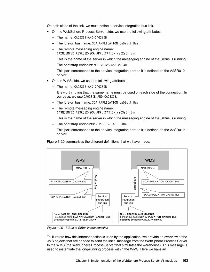
On both sides of the link, we must define a service integration bus link.
� On the WebSphere Process Server side, we use the following attributes:
– The name: CA02SIB-AND-CA03SIB
– The foreign bus name: SCA_APPLICATION_ca02stl_Bus
– The remote messaging engine name: CA2N02MVE2.A2SR012-SCA_APPLICATION_ca02stl_Bus
This is the name of the server in which the messaging engine of the SIBus is running.
– The bootstrap endpoint: 9.212.128.65: 21040
This port corresponds to the service integration port as it is defined on the A2SR012 server.
� On the WMS side, we use the following attributes:
– The name: CA02SIB-AND-CA03SIB
It is worth noting that the same name must be used on each side of the connection. In our case, we use CA02SIB-AND-CA03SIB.
– The foreign bus name: SCA_APPLICATION_ca03stl_Bus– The remote messaging engine name:
CA3N02MVE2.A3SR012-SCA_APPLICATION_ca03stl_Bus
This is the name of the server in which the messaging engine of the SIBus is running.
– The bootstrap endpoints: 9.212.128.65: 31040
This port corresponds to the service integration port as it is defined on the A3SR012 server.
Figure 3-20 summarizes the different definitions that we have made.
Figure 3-20 SIBus to SIBus interconnection
To illustrate how this interconnection is used by the application, we provide an overview of the JMS objects that are needed to send the initial message from the WebSphere Process Server to the WMS (the WebSphere Process Server that simulates the warehouse). This message is used to instantiate the long-running process within the WMS. Here we have an
WPS
SCA SIBus
Foreign Bus
SCA-APPLICATION_CA03stl_Bus
SCA-APPLICATION_CA02stl_Bus Service integration
bus link
Name CA02SIB_AND_CA03SIBForeign bus name SCA-APPLICATION_CA02stl_BusBootstrap endpoints 9.212.128.65:21040
WMS
SCA SIBus
Foreign Bus
SCA-APPLICATION_CA02stl_Bus
SCA-APPLICATION_CA03stl_Bus
Name CA02SIB_AND_CA03SIBForeign bus name SCA-APPLICATION_CA03stl_BusBootstrap endpoints 9.212.128.65:31040
Service integration
bus link
Chapter 3. Implementation of the WebSphere Process Server V6 mock-up 103
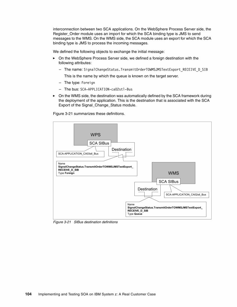
interconnection between two SCA applications. On the WebSphere Process Server side, the Register_Order module uses an import for which the SCA binding type is JMS to send messages to the WMS. On the WMS side, the SCA module uses an export for which the SCA binding type is JMS to process the incoming messages.
We defined the following objects to exchange the initial message:
� On the WebSphere Process Server side, we defined a foreign destination with the following attributes:
– The name: SignalChangeStatus.TransmitOrderTOWMSJMSTextExport_RECEIVE_D_SIB
This is the name by which the queue is known on the target server.
– The type: Foreign
– The bus: SCA-APPLICATION-ca02stl-Bus
� On the WMS side, the destination was automatically defined by the SCA framework during the deployment of the application. This is the destination that is associated with the SCA Export of the Signal_Change_Status module.
Figure 3-21 summarizes these definitions.
Figure 3-21 SIBus destination definitions
WPS
SCA-APPLICATION_CA03stl_BusDestination
Name SignalChangeStatus.TransmitOrderTOWMSJMSTextExport_RECEIVE_D_SIBType Foreign
SCA SIBus
WMS
SCA-APPLICATION_CA02stl_Bus
Destination
Name SignalChangeStatus.TransmitOrderTOWMSJMSTextExport_RECEIVE_D_SIBType Queue
SCA SIBus
104 Implementing and Testing SOA on IBM System z: A Real Customer Case
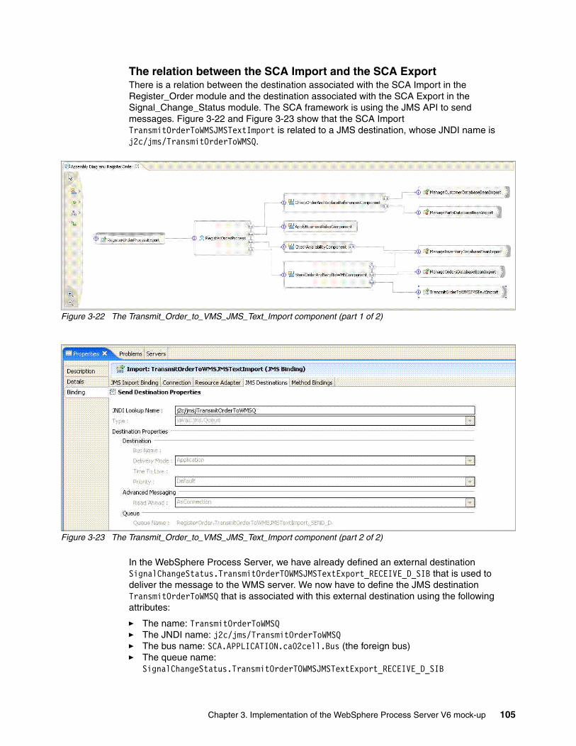
The relation between the SCA Import and the SCA ExportThere is a relation between the destination associated with the SCA Import in the Register_Order module and the destination associated with the SCA Export in the Signal_Change_Status module. The SCA framework is using the JMS API to send messages. Figure 3-22 and Figure 3-23 show that the SCA Import TransmitOrderToWMSJMSTextImport is related to a JMS destination, whose JNDI name is j2c/jms/TransmitOrderToWMSQ.
Figure 3-22 The Transmit_Order_to_VMS_JMS_Text_Import component (part 1 of 2)
Figure 3-23 The Transmit_Order_to_VMS_JMS_Text_Import component (part 2 of 2)
In the WebSphere Process Server, we have already defined an external destination SignalChangeStatus.TransmitOrderTOWMSJMSTextExport_RECEIVE_D_SIB that is used to deliver the message to the WMS server. We now have to define the JMS destination TransmitOrderToWMSQ that is associated with this external destination using the following attributes:
� The name: TransmitOrderToWMSQ� The JNDI name: j2c/jms/TransmitOrderToWMSQ� The bus name: SCA.APPLICATION.ca02cell.Bus (the foreign bus)� The queue name:
SignalChangeStatus.TransmitOrderTOWMSJMSTextExport_RECEIVE_D_SIB
Chapter 3. Implementation of the WebSphere Process Server V6 mock-up 105
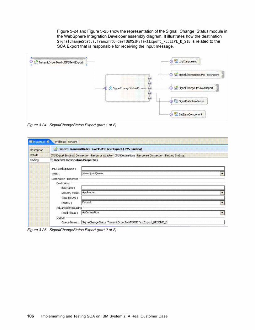
Figure 3-24 and Figure 3-25 show the representation of the Signal_Change_Status module in the WebSphere Integration Developer assembly diagram. It illustrates how the destination SignalChangeStatus.TransmitOrderTOWMSJMSTextExport_RECEIVE_D_SIB is related to the SCA Export that is responsible for receiving the input message.
Figure 3-24 SignalChangeStatus Export (part 1 of 2)
Figure 3-25 SignalChangeStatus Export (part 2 of 2)
106 Implementing and Testing SOA on IBM System z: A Real Customer Case
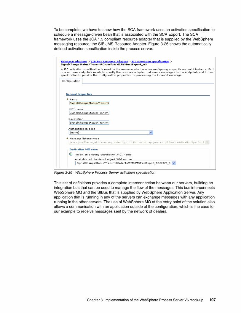
To be complete, we have to show how the SCA framework uses an activation specification to schedule a message-driven bean that is associated with the SCA Export. The SCA framework uses the JCA 1.5 compliant resource adapter that is supplied by the WebSphere messaging resource, the SIB JMS Resource Adapter. Figure 3-26 shows the automatically defined activation specification inside the process server.
Figure 3-26 WebSphere Process Server activation specification
This set of definitions provides a complete interconnection between our servers, building an integration bus that can be used to manage the flow of the messages. This bus interconnects WebSphere MQ and the SIBus that is supplied by WebSphere Application Server. Any application that is running in any of the servers can exchange messages with any application running in the other servers. The use of WebSphere MQ at the entry point of the solution also allows a communication with an application outside of the configuration, which is the case for our example to receive messages sent by the network of dealers.
Chapter 3. Implementation of the WebSphere Process Server V6 mock-up 107

108 Implementing and Testing SOA on IBM System z: A Real Customer Case
Chapter 4. Mock-up extensions
In order to capitalize on a first successful service-oriented architecture (SOA)-business process management (BPM) experience and with the objective to generalize this approach, extensions have been added to the initial SOA-BPM mock-up by Atos Origin. To learn more about Atos Origin, see the following Web address:
http://www.atosorigin.com/en-us/
These additions are related to the following functionality and emerging technologies:
1. Define long-running processes to manage the specific cases in the Create_Order process that has been implemented as a short-running process for performance and resource reasons. These long-running processes are:
– The Held_Order process, which contains one or more manual tasks that allow an operator to manually manage locked orders
This process is activated when a business rule returns a special condition (for example, a “too big quantity” condition) that interrupts the standard processing of an incoming order.
– The Reference_to_Supply process, which is started when the inventory is too low to serve the current order
The BPM model of this process contains an activity that is waiting for an external event that is sent by the Update_Inventory process. When the missing reference is received from the supplier, the inventory database is updated and all the waiting orders are reactivated by an incoming business event.
2. Replace the basic Web interface that is provided by the J2EE front end with a valued WebSphere Portal. WebSphere Portal will run both specific portlets that are written for the Order_Management application and standard portlets that are provided by the BPM engine in order to manage the “Work Items & To Do List” that is required by manual tasks.
The objective is to prove the business value that a well-designed portlet interface can add to an SOA application, based on the BPM engine of WebSphere integration platform V6.
4
© Copyright IBM Corp. 2007. All rights reserved. 109
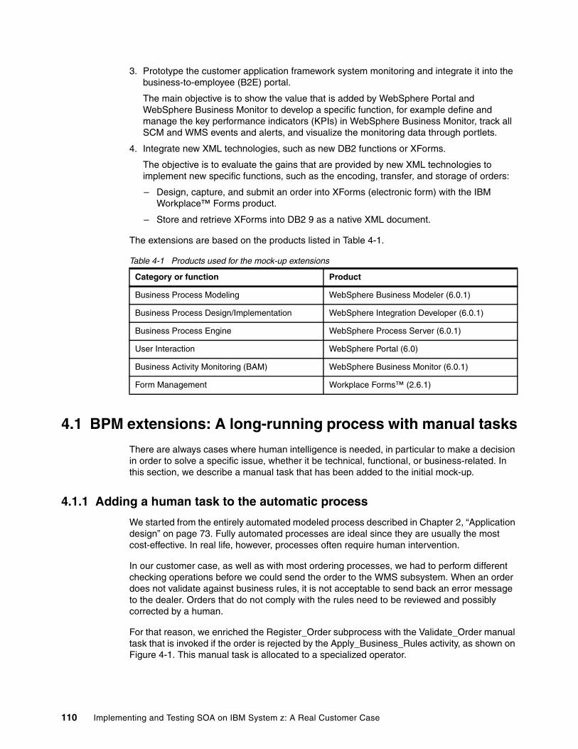
3. Prototype the customer application framework system monitoring and integrate it into the business-to-employee (B2E) portal.
The main objective is to show the value that is added by WebSphere Portal and WebSphere Business Monitor to develop a specific function, for example define and manage the key performance indicators (KPIs) in WebSphere Business Monitor, track all SCM and WMS events and alerts, and visualize the monitoring data through portlets.
4. Integrate new XML technologies, such as new DB2 functions or XForms.
The objective is to evaluate the gains that are provided by new XML technologies to implement new specific functions, such as the encoding, transfer, and storage of orders:
– Design, capture, and submit an order into XForms (electronic form) with the IBM Workplace™ Forms product.
– Store and retrieve XForms into DB2 9 as a native XML document.
The extensions are based on the products listed in Table 4-1.
Table 4-1 Products used for the mock-up extensions
4.1 BPM extensions: A long-running process with manual tasks
There are always cases where human intelligence is needed, in particular to make a decision in order to solve a specific issue, whether it be technical, functional, or business-related. In this section, we describe a manual task that has been added to the initial mock-up.
4.1.1 Adding a human task to the automatic process
We started from the entirely automated modeled process described in Chapter 2, “Application design” on page 73. Fully automated processes are ideal since they are usually the most cost-effective. In real life, however, processes often require human intervention.
In our customer case, as well as with most ordering processes, we had to perform different checking operations before we could send the order to the WMS subsystem. When an order does not validate against business rules, it is not acceptable to send back an error message to the dealer. Orders that do not comply with the rules need to be reviewed and possibly corrected by a human.
For that reason, we enriched the Register_Order subprocess with the Validate_Order manual task that is invoked if the order is rejected by the Apply_Business_Rules activity, as shown on Figure 4-1. This manual task is allocated to a specialized operator.
Category or function Product
Business Process Modeling WebSphere Business Modeler (6.0.1)
Business Process Design/Implementation WebSphere Integration Developer (6.0.1)
Business Process Engine WebSphere Process Server (6.0.1)
User Interaction WebSphere Portal (6.0)
Business Activity Monitoring (BAM) WebSphere Business Monitor (6.0.1)
Form Management Workplace Forms™ (2.6.1)
110 Implementing and Testing SOA on IBM System z: A Real Customer Case
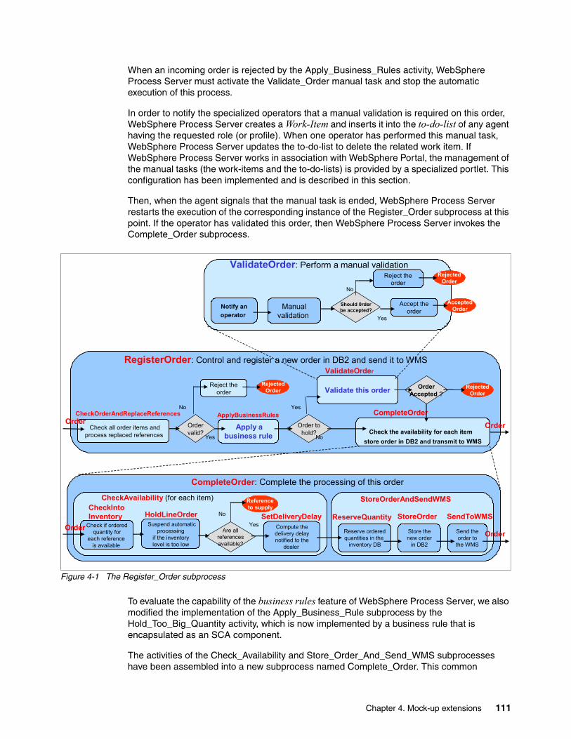
When an incoming order is rejected by the Apply_Business_Rules activity, WebSphere Process Server must activate the Validate_Order manual task and stop the automatic execution of this process.
In order to notify the specialized operators that a manual validation is required on this order, WebSphere Process Server creates a Work-Item and inserts it into the to-do-list of any agent having the requested role (or profile). When one operator has performed this manual task, WebSphere Process Server updates the to-do-list to delete the related work item. If WebSphere Process Server works in association with WebSphere Portal, the management of the manual tasks (the work-items and the to-do-lists) is provided by a specialized portlet. This configuration has been implemented and is described in this section.
Then, when the agent signals that the manual task is ended, WebSphere Process Server restarts the execution of the corresponding instance of the Register_Order subprocess at this point. If the operator has validated this order, then WebSphere Process Server invokes the Complete_Order subprocess.
Figure 4-1 The Register_Order subprocess
To evaluate the capability of the business rules feature of WebSphere Process Server, we also modified the implementation of the Apply_Business_Rule subprocess by the Hold_Too_Big_Quantity activity, which is now implemented by a business rule that is encapsulated as an SCA component.
The activities of the Check_Availability and Store_Order_And_Send_WMS subprocesses have been assembled into a new subprocess named Complete_Order. This common
Yes
No
Reject theorder
RejectedOrder
Apply abusiness rule
CheckOrderAndReplaceReferences ApplyBusinessRules CompleteOrder
Suspend automaticprocessing
if the inventorylevel is too low
Compute thedelivery delaynotified to the
dealer
Are allreferencesavailable?
Yes
No
Referenceto supply
HoldLineOrder SetDeliveryDelay
CheckAvailability (for each item)
Check if ordered quantity for
each reference is available
CheckIntoInventory
Ordervalid?
Order tohold?
Validate this order
Yes
ReserveQuantity
Reserve orderedquantities in the
inventory DB
Order
StoreOrderAndSendWMS
Store thenew order
in DB2
Send theorder to
the WMS
StoreOrder SendToWMS
Order
Check all order items andprocess replaced references Check the availability for each item
store order in DB2 and transmit to WMS
RegisterOrder: Control and register a new order in DB2 and send it to WMS
OrderOrder
No
Should 0rderbe accepted?
No
Yes
Manualvalidation
Notify anoperator
Reject theorder
RejectedOrder
OrderAccepted ?
RejectedOrder
Accept theorder
AcceptedOrder
ValidateOrder: Perform a manual validation
ValidateOrder
CompleteOrder: Complete the processing of this order
Chapter 4. Mock-up extensions 111
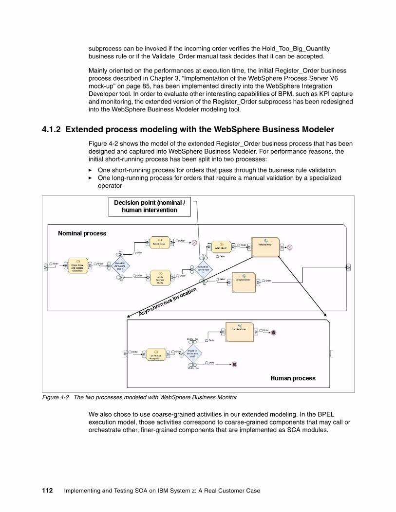
subprocess can be invoked if the incoming order verifies the Hold_Too_Big_Quantity business rule or if the Validate_Order manual task decides that it can be accepted.
Mainly oriented on the performances at execution time, the initial Register_Order business process described in Chapter 3, “Implementation of the WebSphere Process Server V6 mock-up” on page 85, has been implemented directly into the WebSphere Integration Developer tool. In order to evaluate other interesting capabilities of BPM, such as KPI capture and monitoring, the extended version of the Register_Order subprocess has been redesigned into the WebSphere Business Modeler modeling tool.
4.1.2 Extended process modeling with the WebSphere Business Modeler
Figure 4-2 shows the model of the extended Register_Order business process that has been designed and captured into WebSphere Business Modeler. For performance reasons, the initial short-running process has been split into two processes:
� One short-running process for orders that pass through the business rule validation� One long-running process for orders that require a manual validation by a specialized
operator
Figure 4-2 The two processes modeled with WebSphere Business Monitor
We also chose to use coarse-grained activities in our extended modeling. In the BPEL execution model, those activities correspond to coarse-grained components that may call or orchestrate other, finer-grained components that are implemented as SCA modules.
112 Implementing and Testing SOA on IBM System z: A Real Customer Case
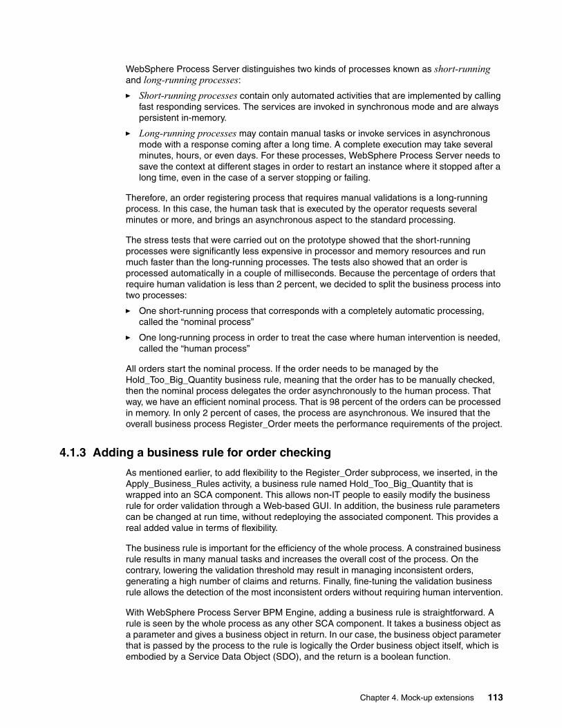
WebSphere Process Server distinguishes two kinds of processes known as short-running and long-running processes:
� Short-running processes contain only automated activities that are implemented by calling fast responding services. The services are invoked in synchronous mode and are always persistent in-memory.
� Long-running processes may contain manual tasks or invoke services in asynchronous mode with a response coming after a long time. A complete execution may take several minutes, hours, or even days. For these processes, WebSphere Process Server needs to save the context at different stages in order to restart an instance where it stopped after a long time, even in the case of a server stopping or failing.
Therefore, an order registering process that requires manual validations is a long-running process. In this case, the human task that is executed by the operator requests several minutes or more, and brings an asynchronous aspect to the standard processing.
The stress tests that were carried out on the prototype showed that the short-running processes were significantly less expensive in processor and memory resources and run much faster than the long-running processes. The tests also showed that an order is processed automatically in a couple of milliseconds. Because the percentage of orders that require human validation is less than 2 percent, we decided to split the business process into two processes:
� One short-running process that corresponds with a completely automatic processing, called the “nominal process”
� One long-running process in order to treat the case where human intervention is needed, called the “human process”
All orders start the nominal process. If the order needs to be managed by the Hold_Too_Big_Quantity business rule, meaning that the order has to be manually checked, then the nominal process delegates the order asynchronously to the human process. That way, we have an efficient nominal process. That is 98 percent of the orders can be processed in memory. In only 2 percent of cases, the process are asynchronous. We insured that the overall business process Register_Order meets the performance requirements of the project.
4.1.3 Adding a business rule for order checking
As mentioned earlier, to add flexibility to the Register_Order subprocess, we inserted, in the Apply_Business_Rules activity, a business rule named Hold_Too_Big_Quantity that is wrapped into an SCA component. This allows non-IT people to easily modify the business rule for order validation through a Web-based GUI. In addition, the business rule parameters can be changed at run time, without redeploying the associated component. This provides a real added value in terms of flexibility.
The business rule is important for the efficiency of the whole process. A constrained business rule results in many manual tasks and increases the overall cost of the process. On the contrary, lowering the validation threshold may result in managing inconsistent orders, generating a high number of claims and returns. Finally, fine-tuning the validation business rule allows the detection of the most inconsistent orders without requiring human intervention.
With WebSphere Process Server BPM Engine, adding a business rule is straightforward. A rule is seen by the whole process as any other SCA component. It takes a business object as a parameter and gives a business object in return. In our case, the business object parameter that is passed by the process to the rule is logically the Order business object itself, which is embodied by a Service Data Object (SDO), and the return is a boolean function.
Chapter 4. Mock-up extensions 113
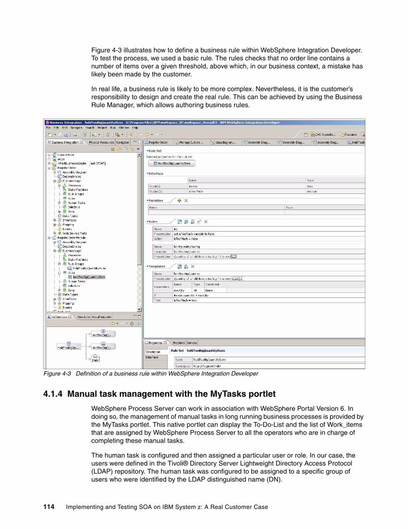
Figure 4-3 illustrates how to define a business rule within WebSphere Integration Developer. To test the process, we used a basic rule. The rules checks that no order line contains a number of items over a given threshold, above which, in our business context, a mistake has likely been made by the customer.
In real life, a business rule is likely to be more complex. Nevertheless, it is the customer’s responsibility to design and create the real rule. This can be achieved by using the Business Rule Manager, which allows authoring business rules.
Figure 4-3 Definition of a business rule within WebSphere Integration Developer
4.1.4 Manual task management with the MyTasks portlet
WebSphere Process Server can work in association with WebSphere Portal Version 6. In doing so, the management of manual tasks in long running business processes is provided by the MyTasks portlet. This native portlet can display the To-Do-List and the list of Work_items that are assigned by WebSphere Process Server to all the operators who are in charge of completing these manual tasks.
The human task is configured and then assigned a particular user or role. In our case, the users were defined in the Tivoli® Directory Server Lightweight Directory Access Protocol (LDAP) repository. The human task was configured to be assigned to a specific group of users who were identified by the LDAP distinguished name (DN).
114 Implementing and Testing SOA on IBM System z: A Real Customer Case
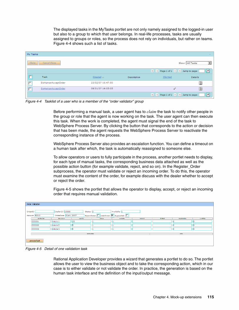
The displayed tasks in the MyTasks portlet are not only namely assigned to the logged-in user but also to a group to which that user belongs. In real-life processes, tasks are usually assigned to groups or roles, so the process does not rely on individuals, but rather on teams. Figure 4-4 shows such a list of tasks.
Figure 4-4 Tasklist of a user who is a member of the “order validator” group
Before performing a manual task, a user agent has to claim the task to notify other people in the group or role that the agent is now working on the task. The user agent can then execute this task. When the work is completed, the agent must signal the end of the task to WebSphere Process Server. By clicking the button that corresponds to the action or decision that has been made, the agent requests the WebSphere Process Server to reactivate the corresponding instance of the process.
WebSphere Process Server also provides an escalation function. You can define a timeout on a human task after which, the task is automatically reassigned to someone else.
To allow operators or users to fully participate in the process, another portlet needs to display, for each type of manual tasks, the corresponding business data attached as well as the possible action button (for example validate, reject, and so on). In the Register_Order subprocess, the operator must validate or reject an incoming order. To do this, the operator must examine the content of the order, for example discuss with the dealer whether to accept or reject the order.
Figure 4-5 shows the portlet that allows the operator to display, accept, or reject an incoming order that requires manual validation.
Figure 4-5 Detail of one validation task
Rational Application Developer provides a wizard that generates a portlet to do so. The portlet allows the user to view the business object and to take the corresponding action, which in our case is to either validate or not validate the order. In practice, the generation is based on the human task interface and the definition of the input/output message.
Chapter 4. Mock-up extensions 115
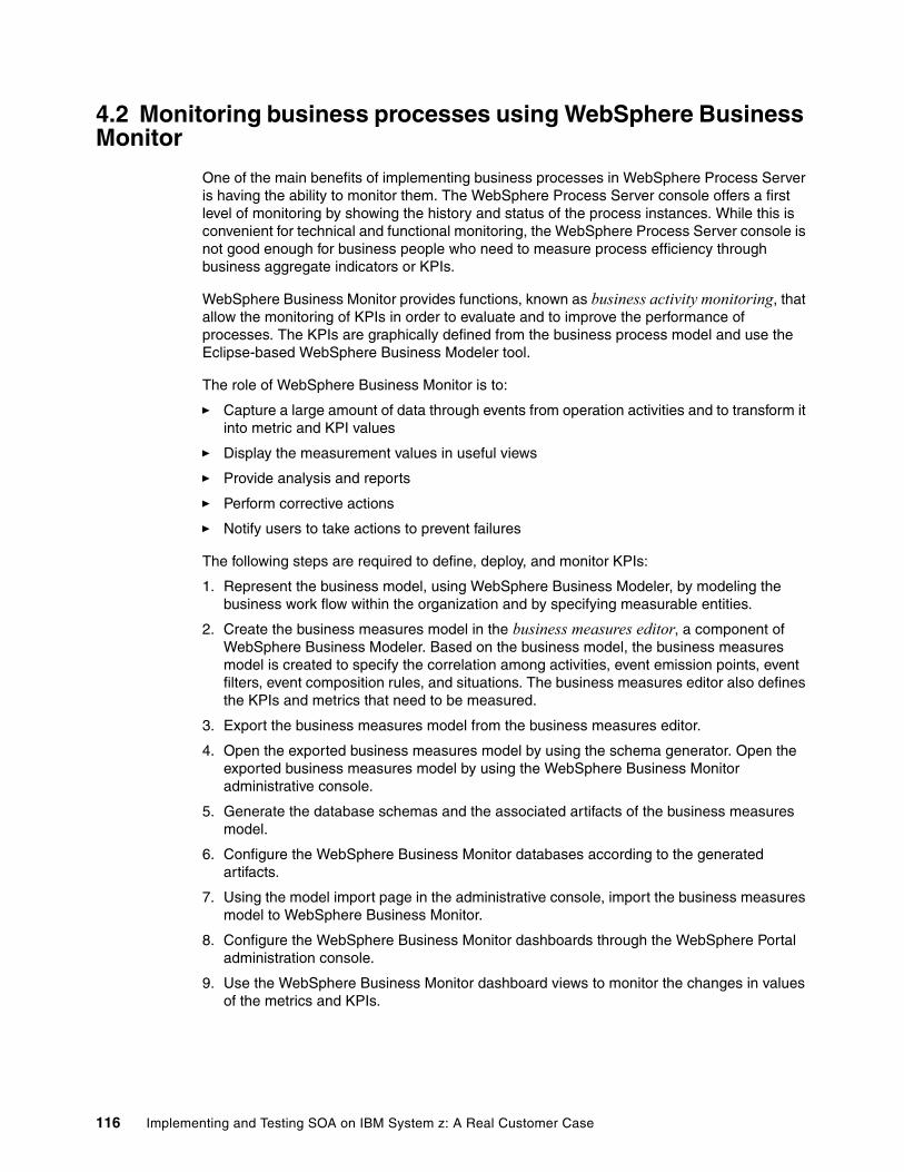
4.2 Monitoring business processes using WebSphere Business Monitor
One of the main benefits of implementing business processes in WebSphere Process Server is having the ability to monitor them. The WebSphere Process Server console offers a first level of monitoring by showing the history and status of the process instances. While this is convenient for technical and functional monitoring, the WebSphere Process Server console is not good enough for business people who need to measure process efficiency through business aggregate indicators or KPIs.
WebSphere Business Monitor provides functions, known as business activity monitoring, that allow the monitoring of KPIs in order to evaluate and to improve the performance of processes. The KPIs are graphically defined from the business process model and use the Eclipse-based WebSphere Business Modeler tool.
The role of WebSphere Business Monitor is to:
� Capture a large amount of data through events from operation activities and to transform it into metric and KPI values
� Display the measurement values in useful views
� Provide analysis and reports
� Perform corrective actions
� Notify users to take actions to prevent failures
The following steps are required to define, deploy, and monitor KPIs:
1. Represent the business model, using WebSphere Business Modeler, by modeling the business work flow within the organization and by specifying measurable entities.
2. Create the business measures model in the business measures editor, a component of WebSphere Business Modeler. Based on the business model, the business measures model is created to specify the correlation among activities, event emission points, event filters, event composition rules, and situations. The business measures editor also defines the KPIs and metrics that need to be measured.
3. Export the business measures model from the business measures editor.
4. Open the exported business measures model by using the schema generator. Open the exported business measures model by using the WebSphere Business Monitor administrative console.
5. Generate the database schemas and the associated artifacts of the business measures model.
6. Configure the WebSphere Business Monitor databases according to the generated artifacts.
7. Using the model import page in the administrative console, import the business measures model to WebSphere Business Monitor.
8. Configure the WebSphere Business Monitor dashboards through the WebSphere Portal administration console.
9. Use the WebSphere Business Monitor dashboard views to monitor the changes in values of the metrics and KPIs.
116 Implementing and Testing SOA on IBM System z: A Real Customer Case
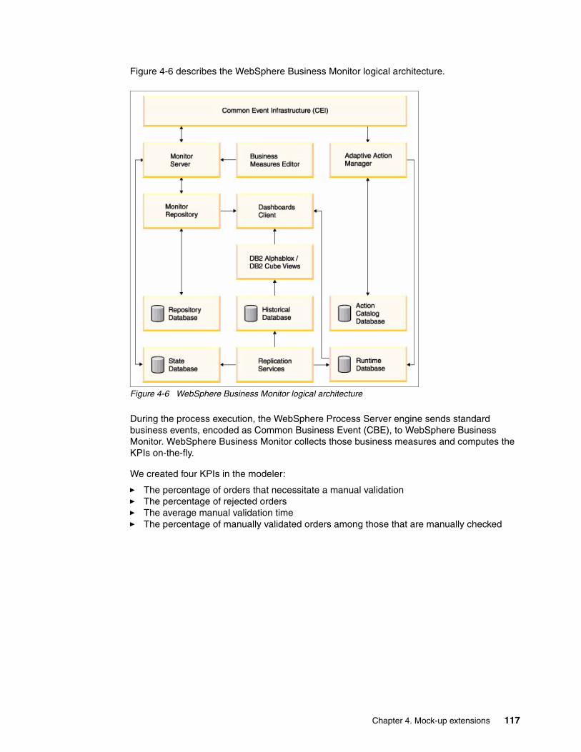
Figure 4-6 describes the WebSphere Business Monitor logical architecture.
Figure 4-6 WebSphere Business Monitor logical architecture
During the process execution, the WebSphere Process Server engine sends standard business events, encoded as Common Business Event (CBE), to WebSphere Business Monitor. WebSphere Business Monitor collects those business measures and computes the KPIs on-the-fly.
We created four KPIs in the modeler:
� The percentage of orders that necessitate a manual validation� The percentage of rejected orders� The average manual validation time� The percentage of manually validated orders among those that are manually checked
Chapter 4. Mock-up extensions 117
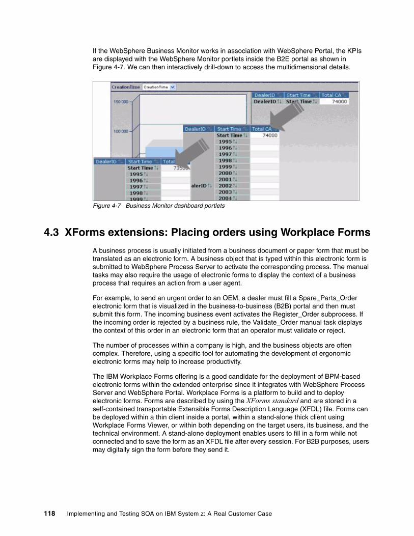
If the WebSphere Business Monitor works in association with WebSphere Portal, the KPIs are displayed with the WebSphere Monitor portlets inside the B2E portal as shown in Figure 4-7. We can then interactively drill-down to access the multidimensional details.
Figure 4-7 Business Monitor dashboard portlets
4.3 XForms extensions: Placing orders using Workplace Forms
A business process is usually initiated from a business document or paper form that must be translated as an electronic form. A business object that is typed within this electronic form is submitted to WebSphere Process Server to activate the corresponding process. The manual tasks may also require the usage of electronic forms to display the context of a business process that requires an action from a user agent.
For example, to send an urgent order to an OEM, a dealer must fill a Spare_Parts_Order electronic form that is visualized in the business-to-business (B2B) portal and then must submit this form. The incoming business event activates the Register_Order subprocess. If the incoming order is rejected by a business rule, the Validate_Order manual task displays the context of this order in an electronic form that an operator must validate or reject.
The number of processes within a company is high, and the business objects are often complex. Therefore, using a specific tool for automating the development of ergonomic electronic forms may help to increase productivity.
The IBM Workplace Forms offering is a good candidate for the deployment of BPM-based electronic forms within the extended enterprise since it integrates with WebSphere Process Server and WebSphere Portal. Workplace Forms is a platform to build and to deploy electronic forms. Forms are described by using the XForms standard and are stored in a self-contained transportable Extensible Forms Description Language (XFDL) file. Forms can be deployed within a thin client inside a portal, within a stand-alone thick client using Workplace Forms Viewer, or within both depending on the target users, its business, and the technical environment. A stand-alone deployment enables users to fill in a form while not connected and to save the form as an XFDL file after every session. For B2B purposes, users may digitally sign the form before they send it.
118 Implementing and Testing SOA on IBM System z: A Real Customer Case
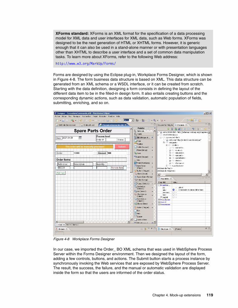
Forms are designed by using the Eclipse plug-in, Workplace Forms Designer, which is shown in Figure 4-8. The form business data structure is based on XML. This data structure can be generated from an XML schema or a WSDL interface, or it can be created from scratch. Starting with the data definition, designing a form consists in defining the layout of the different data item to be in the filled-in design form. It also entails creating buttons and the corresponding dynamic actions, such as data validation, automatic population of fields, submitting, enriching, and so on.
Figure 4-8 Workplace Forms Designer
In our case, we imported the Order_ BO XML schema that was used in WebSphere Process Server within the Forms Designer environment. Then we designed the layout of the form, adding a few controls, buttons, and actions. The Submit button starts a process instance by synchronously invoking the Web services that are exposed by WebSphere Process Server. The result, the success, the failure, and the manual or automatic validation are displayed inside the form so that the users are informed of the order status.
XForms standard: XForms is an XML format for the specification of a data processing model for XML data and user interfaces for XML data, such as Web forms. XForms was designed to be the next generation of HTML or XHTML forms. However, it is generic enough that it can also be used in a stand-alone manner or with presentation languages other than XHTML to describe a user interface and a set of common data manipulation tasks. To learn more about XForms, refer to the following Web address:
http://www.w3.org/MarkUp/Forms/
Chapter 4. Mock-up extensions 119
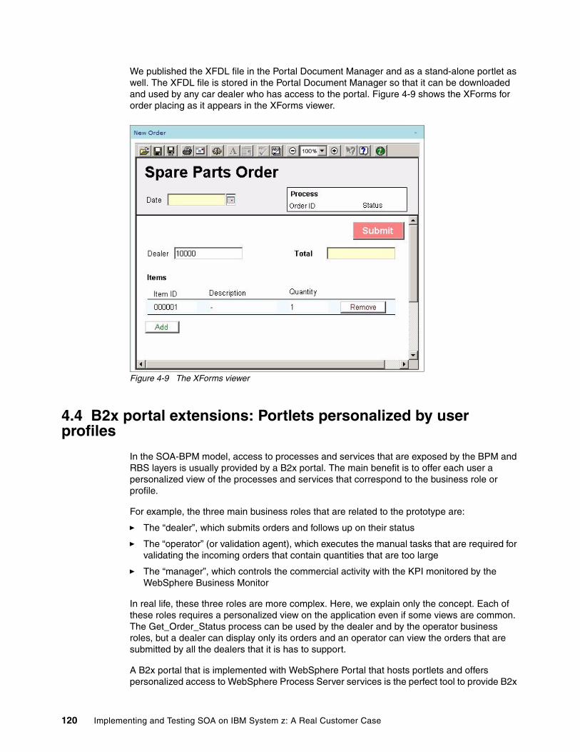
We published the XFDL file in the Portal Document Manager and as a stand-alone portlet as well. The XFDL file is stored in the Portal Document Manager so that it can be downloaded and used by any car dealer who has access to the portal. Figure 4-9 shows the XForms for order placing as it appears in the XForms viewer.
Figure 4-9 The XForms viewer
4.4 B2x portal extensions: Portlets personalized by user profiles
In the SOA-BPM model, access to processes and services that are exposed by the BPM and RBS layers is usually provided by a B2x portal. The main benefit is to offer each user a personalized view of the processes and services that correspond to the business role or profile.
For example, the three main business roles that are related to the prototype are:
� The “dealer”, which submits orders and follows up on their status
� The “operator” (or validation agent), which executes the manual tasks that are required for validating the incoming orders that contain quantities that are too large
� The “manager”, which controls the commercial activity with the KPI monitored by the WebSphere Business Monitor
In real life, these three roles are more complex. Here, we explain only the concept. Each of these roles requires a personalized view on the application even if some views are common. The Get_Order_Status process can be used by the dealer and by the operator business roles, but a dealer can display only its orders and an operator can view the orders that are submitted by all the dealers that it is has to support.
A B2x portal that is implemented with WebSphere Portal that hosts portlets and offers personalized access to WebSphere Process Server services is the perfect tool to provide B2x
120 Implementing and Testing SOA on IBM System z: A Real Customer Case
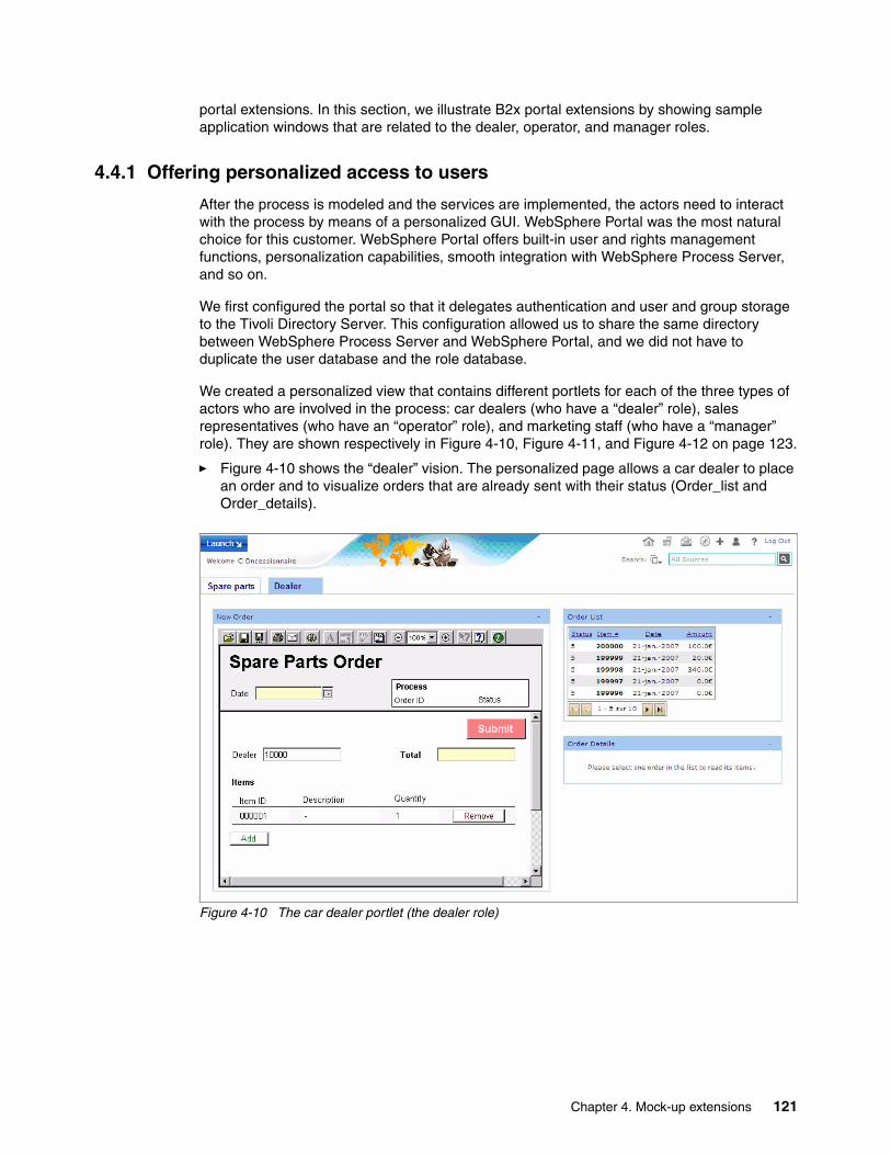
portal extensions. In this section, we illustrate B2x portal extensions by showing sample application windows that are related to the dealer, operator, and manager roles.
4.4.1 Offering personalized access to users
After the process is modeled and the services are implemented, the actors need to interact with the process by means of a personalized GUI. WebSphere Portal was the most natural choice for this customer. WebSphere Portal offers built-in user and rights management functions, personalization capabilities, smooth integration with WebSphere Process Server, and so on.
We first configured the portal so that it delegates authentication and user and group storage to the Tivoli Directory Server. This configuration allowed us to share the same directory between WebSphere Process Server and WebSphere Portal, and we did not have to duplicate the user database and the role database.
We created a personalized view that contains different portlets for each of the three types of actors who are involved in the process: car dealers (who have a “dealer” role), sales representatives (who have an “operator” role), and marketing staff (who have a “manager” role). They are shown respectively in Figure 4-10, Figure 4-11, and Figure 4-12 on page 123.
� Figure 4-10 shows the “dealer” vision. The personalized page allows a car dealer to place an order and to visualize orders that are already sent with their status (Order_list and Order_details).
Figure 4-10 The car dealer portlet (the dealer role)
Chapter 4. Mock-up extensions 121
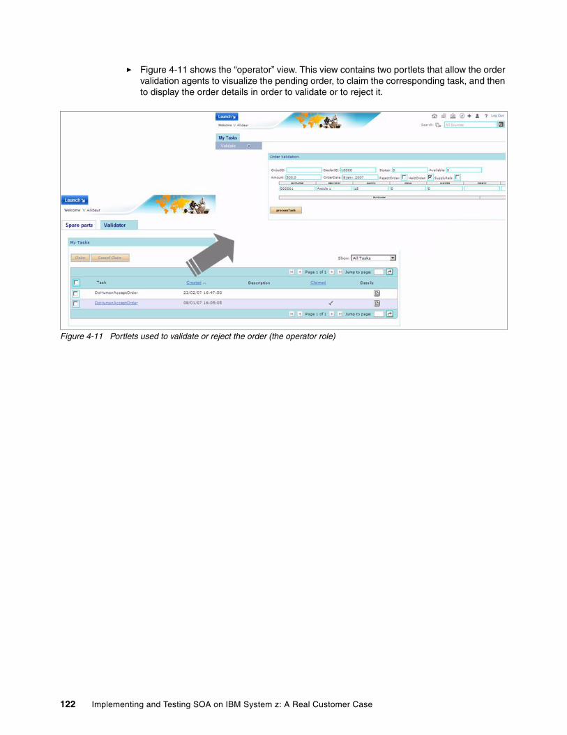
� Figure 4-11 shows the “operator” view. This view contains two portlets that allow the order validation agents to visualize the pending order, to claim the corresponding task, and then to display the order details in order to validate or to reject it.
Figure 4-11 Portlets used to validate or reject the order (the operator role)
122 Implementing and Testing SOA on IBM System z: A Real Customer Case
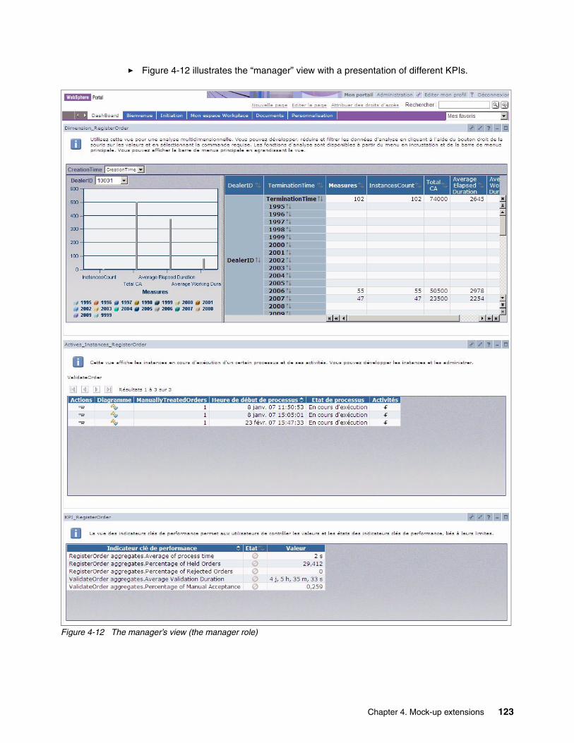
� Figure 4-12 illustrates the “manager” view with a presentation of different KPIs.
Figure 4-12 The manager’s view (the manager role)
Chapter 4. Mock-up extensions 123
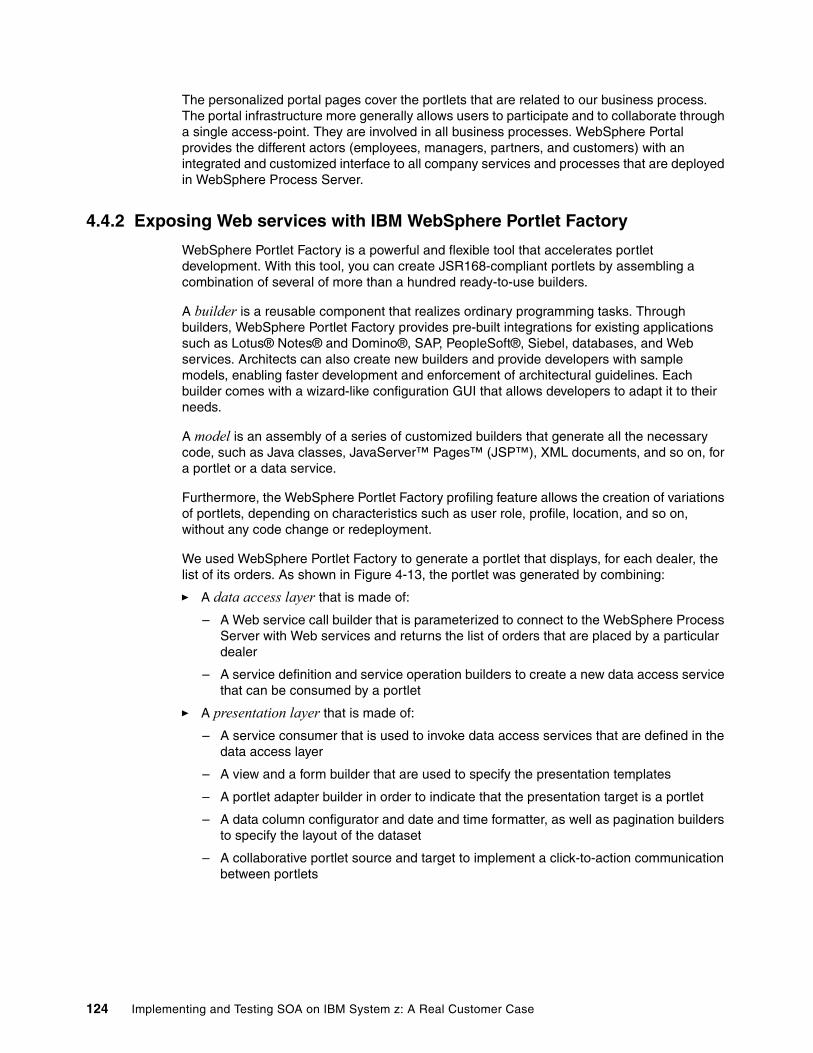
The personalized portal pages cover the portlets that are related to our business process. The portal infrastructure more generally allows users to participate and to collaborate through a single access-point. They are involved in all business processes. WebSphere Portal provides the different actors (employees, managers, partners, and customers) with an integrated and customized interface to all company services and processes that are deployed in WebSphere Process Server.
4.4.2 Exposing Web services with IBM WebSphere Portlet Factory
WebSphere Portlet Factory is a powerful and flexible tool that accelerates portlet development. With this tool, you can create JSR168-compliant portlets by assembling a combination of several of more than a hundred ready-to-use builders.
A builder is a reusable component that realizes ordinary programming tasks. Through builders, WebSphere Portlet Factory provides pre-built integrations for existing applications such as Lotus® Notes® and Domino®, SAP, PeopleSoft®, Siebel, databases, and Web services. Architects can also create new builders and provide developers with sample models, enabling faster development and enforcement of architectural guidelines. Each builder comes with a wizard-like configuration GUI that allows developers to adapt it to their needs.
A model is an assembly of a series of customized builders that generate all the necessary code, such as Java classes, JavaServer™ Pages™ (JSP™), XML documents, and so on, for a portlet or a data service.
Furthermore, the WebSphere Portlet Factory profiling feature allows the creation of variations of portlets, depending on characteristics such as user role, profile, location, and so on, without any code change or redeployment.
We used WebSphere Portlet Factory to generate a portlet that displays, for each dealer, the list of its orders. As shown in Figure 4-13, the portlet was generated by combining:
� A data access layer that is made of:
– A Web service call builder that is parameterized to connect to the WebSphere Process Server with Web services and returns the list of orders that are placed by a particular dealer
– A service definition and service operation builders to create a new data access service that can be consumed by a portlet
� A presentation layer that is made of:
– A service consumer that is used to invoke data access services that are defined in the data access layer
– A view and a form builder that are used to specify the presentation templates
– A portlet adapter builder in order to indicate that the presentation target is a portlet
– A data column configurator and date and time formatter, as well as pagination builders to specify the layout of the dataset
– A collaborative portlet source and target to implement a click-to-action communication between portlets
124 Implementing and Testing SOA on IBM System z: A Real Customer Case
Figure 4-13 A portlet generated with WebSphere Portlet Factory
More generally, WebSphere Portlet Factory enables fast development of portlets that interact with Web services. WebSphere Process Server and WebSphere Portlet Factory are therefore complementary. WebSphere Portlet Factory can invoke business services that are developed in WebSphere Process Server, in our case, for example Get_Order_By_Dealer, Get_Order_Status, Get_Number_Of_Order_By_Dealer, and so on.
To learn more about WebSphere Portlet Factory, refer to the WebSphere Portlet Factory product documentation Web page at the following address:
http://www-128.ibm.com/developerworks/websphere/zones/portal/portletfactory/proddoc.html
Chapter 4. Mock-up extensions 125

126 Implementing and Testing SOA on IBM System z: A Real Customer Case
Chapter 5. From the current architecture to the SOA: A migration experience
The estimations of the preliminary study have shown that a complete replacement of the old system at one time would be an expensive, risky, and long process. In order to reduce the costs, risks, and delays that are required to realize the new OM components, the existing IMS code of the former OM subsystem can be partially reused. Only the strategic functions that bring value to the business are rewritten in Java. The other functions remain under IMS after a conversion of the old obsolete language (OL) code into the Enterprise Generation Language (EGL).
To allow a smooth and easy migration, the new system under WebSphere Process Server must support a long cohabitation with the former system under IMS. In order to validate these major principles, it was decided to build a new prototype that will also be the foundation of the new system. Later this prototype may be upgraded with real application code to become the first production deliverable of the project.
In this chapter, we discuss the following items:
� A generic solution for OL eradication that is partially based on a conversion into the EGL
� The target architecture of the new system that integrates the existing IMS assets (EGL modules and DL/I databases) with the new WebSphere resources (Java components and DB2 databases)
� The architecture of the prototype, which aims to validate the target and migration process
� The additional technologies that are required by this target architecture, WebSphere Enterprise Service Bus (ESB) and IMS/JCA connector, and a DL/I/DB2 synchronization solution
5
Obsolete language: OL is a generic name for a specific customer programming language that was chosen for this book. The customer is using an internal name that we do not mention in this book.
Note: Tests for implementing the prototype will start in September 2007. Once the tests are complete, we may update this book with the results.
© Copyright IBM Corp. 2007. All rights reserved. 127
5.1 A generic solution to eradicate the obsolete language
The obsolete language is a specific internal tool that was developed by the customer in the 1970s to accelerate the writing of applications in an IBM OS/390® environment. This language was compiled on the fly, with the syntax of third-generation programming language (3GL) such as Cobol and PL/I. It is associated with a powerful development environment and and an equivalent language was not on the market during this time.
Over the period of more than 30 years since the tool was developed, the OL was supported and maintained as the result of two main forces:
� Excellent productivity of development
In particular, the OL offered efficient management of 3270 screens for IMS, CICS, and Time Sharing Options (TSO). It also eliminated the compilation and link-edit steps; we code and test immediately.
� A low requirement for hardware resources, similar to the Assembly language
Today however, the weaknesses that result from using such a specific internal tool have resulted in critical issues:
� Technical support has become difficult and risky because of the lack of skills.
As a result, continued use of the language may stop the evolution and implementation of the main operating systems and middleware, such as z/OS, IMS, or DB2. Or its use may result in complex bugs that require a long time to correct.
� Because of 3GL marginalization, the language has become isolated and less productive.
We must stress two important points:
� The OL is the technology base of major, complex systems. The OL accounts for the coding of 25 percent of automated functions and about 40 percent of the critical applications. The replacement of large systems is expensive and risky. Several projects were canceled at the end of a preliminary study because of the costs and risks with a “big bang” OL replacement.
� Rewriting the OL code in Cobol or PL/I would be a delicate and expensive operation. Such a task would entail an intense interleaving of the functions, understanding a logic that is specific to the OL, managing and redoing many screens, reviewing obsolete documentation, and so on. A complete translation would not resolve the problem of the old tool being obsolete. Nor would it simplify evolution to new systems or new business processes.
5.1.1 Enterprise Generation Language overview
EGL is a development environment and a structured programming language. IBM EGL is a procedural language that is used for the development of business application programs. The term enterprise, as in Enterprise Generation Language, indicates that EGL can satisfy the programming requirements across the entire enterprise.
For example, with EGL, we can deliver intranet, extranet, and Internet applications, including Web services. With EGL, we can develop business application programs with no user interface, text user interface, nor multi-tier graphical Web interface. EGL is not a product, per se, but rather a capability that is part of Rational Web Developer, Rational Application Developer, Rational Enterprise Developer, and so on. The EGL product capability is an optional, installable component.
128 Implementing and Testing SOA on IBM System z: A Real Customer Case
In this section, we describe the programming simplification that is provided by EGL as well as its benefits.
Empowered developmentEGL is a simplified high-level programming language that lets you write full-function applications quickly. It enables you to focus on business problems rather than complex underlying technologies. For example, EGL hides all the complexity of Java and J2EE coding, so you can deliver enterprise data to Web browsers with minimal Internet technology experience.
EGL is included into the IBM Rational Software Delivery Platform. It integrates several rapid development technologies within the Eclipse Open Source framework to offer a highly productive environment.
At the most basic level, EGL is a procedural language that can be used by business developers to implement new applications quickly. The word generation in the name implies that the business logic written in EGL will be transformed into Java or COBOL and runtime artifacts that can be deployed to a number of different target platforms.
In a broader and more comprehensive definition, EGL is not only a language but a highly productive development environment. Integrated into the Rational Software Delivery Platform, EGL improves productivity not only with language abstraction and simplicity but also by the integration of other key Internet technologies such as JavaServer Faces (JSF) or Web services.
EGL provides a simplified approach to application development based on the following principles:
� Simplifying the specification
EGL provides an easy-to-learn programming paradigm that abstracts the underlying technology. Developers are shielded from the complexities of runtime environments. This results in reduced training costs and a great improvement in productivity.
� Code generation
High productivity comes from the ability to transform technology-neutral logic into optimized code for the target runtime platform. This results in less code written by the developer and a reduced number of bugs in the application.
� Application flexibility
It supports service-oriented architecture (SOA), Web services, J2EE applications, and character-based green-screen IMS or CICS applications and batch or reporting applications.
� Data source independence
Access is available to a broad range of data sources including SQL DBMS via ODBC/JDBC technology, message queuing (WebSphere MQ), sequential and VSAM files, and hierarchical data structures (IMS or DL/I).
� EGL-based debugging
Source-level debugging is provided without generating the target platform code. This function enables complete, end-to-end isolation from the complexity of the underlying technology.
� Platform neutrality
Cross-platform application deployment or implementation is supported and includes the System z with IMS or CICS transactions and batch applications.
Chapter 5. From the current architecture to the SOA: A migration experience 129
Benefits of EGLMany companies have decided to adopt the J2EE and Web services standards because of the benefits of these technologies. However, the pool of available COBOL or 4GL developers cannot be simply retrained in Java and J2EE. The cost of such training is usually estimated by consultants to about USD$20,000 per developer. The time required to acquire good expertise in these object-oriented technologies may be incompatible with the business needs.
As a modern and powerful development environment, EGL can address this big challenge. Fully integrated into the Rational Software Delivery Platform, EGL is an enabling tool that helps your current COBOL developers to use the latest internet technologies with minimal costs and effort.
EGL empowers this broader class of professional developers with several key values:
� Ability to build Java/J2EE based applications without a deep knowledge of the underlying technology
� Delivery of new applications based on industry standards, such as J2EE and Web services, that interoperate with existing systems such as IMS or CICS applications
� Development of service-oriented applications and reusable business services without an extensive knowledge of SOA technologies
� Reduced training costs while leveraging existing business developer skills
� Achievement of a high level of productivity by leveraging the latest Internet technologies
� Reduced application errors through automation and code generation
� Automated deployment to all IBM platforms including the System z platform
5.1.2 Solutions to eradicate the obsolete language
The customer works around two generic solutions to secure its existing architecture:
� For the client or service applications, coded in OL/Cobol under IMS or CICS with a WebSphere front end (the more recent systems), a direct conversion in Cobol is conceivable. The process is simple. We compile the OL code of the client or service applications with the standard Cobol compiler. Then we correct the errors and test the resulting transactions.
This may be the solution to retain for a few recent strategic systems that mix each Java or WebSphere front end with an IMS/OL/Cobol (or CICS/OL/Cobol) back end.
� For the OL/3270 applications that are coded in OL/Cobol or OL/PL/I, which are usually old systems, the customer works with IBM on the conversion of existing OL programs to EGL, to generate Cobol (or Java) code for IMS or CICS, with a 3270 interface (or Web GUI). Rather than do a direct conversion in Cobol, using EGL is a good solution because:
– It allows the customer to keep specific logic of the existing OL transactions.– It offers management of 3270 screens that is equivalent to OL maps.
5.1.3 Automating the conversion to EGL
With the help of IBM, the customer converted the first OL/PLI program, which contained approximately 1,000 lines of code, into EGL. After this successful, manual transposition, which maintains the structure and the maps that define the 3270 screens, the customer is already working to automate the conversion. The customer works using an Open Source tool that is capable of parsing the OL code and translating it into EGL.
130 Implementing and Testing SOA on IBM System z: A Real Customer Case
By the time this book was written, a dozen of OL or PL/I programs were automatically converted. The results of the conversion of the OL code and 3270 maps have been satisfactory. Now a first application needs to be tested to verify that the generated code works well and to estimate the workload of a complete conversion. Next the customer must define the future industrial process that will allow the realization of successful massive conversions.
Even if the transposition of OL code into EGL can be partially automated, it remains an expensive solution. In every case, the tests and acceptance of the resulting code constitute an important workload. It is necessary to revise, and sometimes rewrite, the documentation. In addition, for old systems, it may be necessary to review the specifications.
Furthermore, a conversion in EGL brings no business value, except for secure code. Therefore, this solution will not be implemented for all of the applications that are coded in OL.
5.1.4 Combining conversion and rewriting
A massive and partially automated conversion to EGL is only one part of a potential answer; it cannot be a universal solution. For old complex systems, such as the spare part distribution application that is described in this document, replacement is risky. In addition, the costs of a massive conversion into EGL are not worth the results:
� This solution does not solve the problems due to the obsolescence. We keep the data models with their limitation, for example old DL/I databases, as well as strong functional gaps, unused functions, and expensive redundancy.
� This solution does not facilitate the evolution that is requested by the business.
� This solution does not decrease the cost of maintenance.
A good solution is often a renovation or progressive renewal that combines conversion and rewriting within the framework of the WebSphere integration platform. A partial conversion of OL to EGL allows secure non-strategic functions and therefore, reduces the costs, delays, and risks, compared to a complete replacement of the old system.
To optimize the investment required to eradicate OL, the main idea is to:
1. Rewrite the most strategic functions (in Java under WebSphere) to bring business value.
2. Convert the other functions in EGL, by keeping them under IMS, to limit the costs, delays, and risks.
5.1.5 Three classes of applications
In a combined technical study, the customer and IBM have classified the OL applications into three categories:
� Category 1: Do nothing, which means freeze the technical and application environment for the old applications that will be withdrawn or replaced in the next five years.
� Category 2: Engage in a complete transposition of the existing OL code to either of the languages:
– Cobol for the recent client/service systems that are coded in OL/Cobol– EGL for the old OL/3270 applications that globally meet the business needs
� Category 3: Gradually renew the application for the old systems that must be modernized; this renewal is made according to the SOA target vision, with a reuse, after a conversion into EGL, of the nonstrategic functions to optimize the investment.
Chapter 5. From the current architecture to the SOA: A migration experience 131
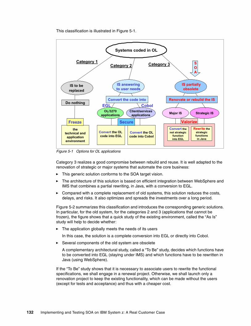
This classification is illustrated in Figure 5-1.
Figure 5-1 Options for OL applications
Category 3 realizes a good compromise between rebuild and reuse. It is well adapted to the renovation of strategic or major systems that automate the core business:
� This generic solution conforms to the SOA target vision.
� The architecture of this solution is based on efficient integration between WebSphere and IMS that combines a partial rewriting, in Java, with a conversion to EGL.
� Compared with a complete replacement of old systems, this solution reduces the costs, delays, and risks. It also optimizes and spreads the investments over a long period.
Figure 5-2 summarizes this classification and introduces the corresponding generic solutions. In particular, for the old system, for the categories 2 and 3 (applications that cannot be frozen), the figure shows that a quick study of the existing environment, called the “As Is” study will help to decide whether:
� The application globally meets the needs of its users
In this case, the solution is a complete conversion into EGL or directly into Cobol.
� Several components of the old system are obsolete
A complementary architectural study, called a “To Be” study, decides which functions have to be converted into EGL (staying under IMS) and which functions have to be rewritten in Java (using WebSphere).
If the “To Be” study shows that it is necessary to associate users to rewrite the functional specifications, we shall engage in a renewal project. Otherwise, we shall launch only a renovation project to keep the existing functionality, which can be made without the users (except for tests and acceptance) and thus with a cheaper cost.
Systems coded in OL
IS to be replaced
IS partiallyobsolete
Major IS Strategic IS
IS answeringto user needs
OL/3270applications
Client/servicesapplications
Convert thenot strategic
functioninto EGL
Convert the OLcode into Cobol
Convert the OL code into EGL
thetechnical and
applicationenvironment
Renovate or rebuild the ISConvert the code intoDo nothing
EGL Cobol
Category 1Category 2 Category 3
Rewrite thestrategicfunctionsin Java
SOA
Secure ValorizeFreeze
132 Implementing and Testing SOA on IBM System z: A Real Customer Case
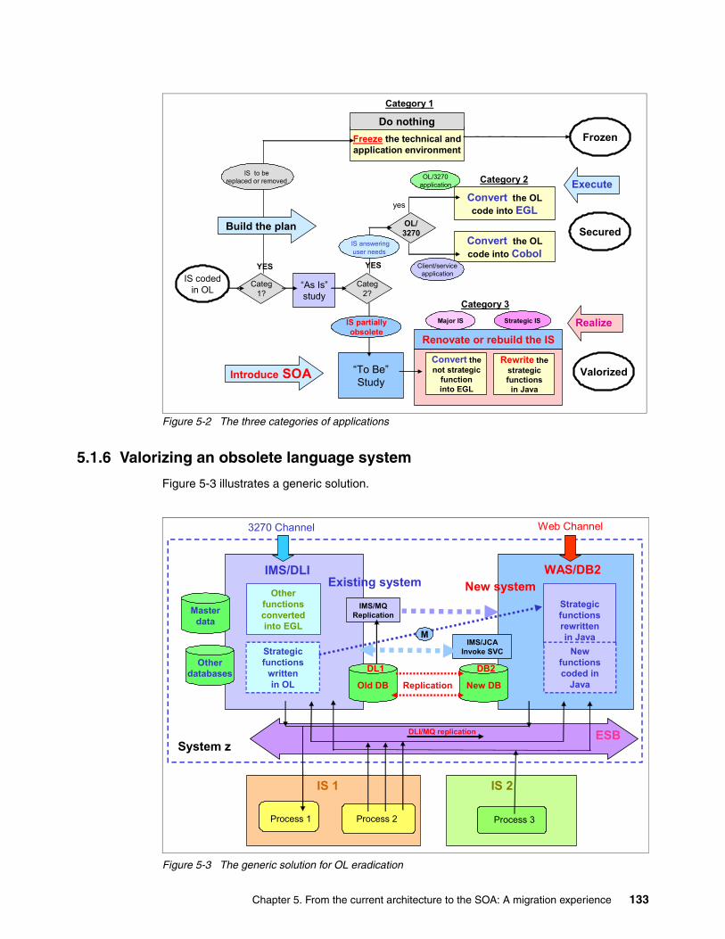
Figure 5-2 The three categories of applications
5.1.6 Valorizing an obsolete language system
Figure 5-3 illustrates a generic solution.
Figure 5-3 The generic solution for OL eradication
IS codedin OL
Frozen
Categ1?
Categ2?
Freeze the technical andapplication environment
Convert the OLcode into EGL
OL/3270
Convert the OLcode into Cobol
Renovate or rebuild the IS
Secured
Valorized“To Be”Study
“As Is”study
Do nothing
IS to bereplaced or removed
IS answeringuser needs
IS partiallyobsolete
Client/serviceapplication
OL/3270application
Major IS Strategic IS
Category 1
YES YES
yes
Introduce SOA
Realize
Execute Category 2
Category 3
Convert thenot strategic
functioninto EGL
Rewrite thestrategicfunctions
in Java
Build the plan
WAS/DB2
Process 2
IS 1
IMS/DLI
Process 3
Old DB
Masterdata
Otherdatabases
New DB
DL1 DB2
Process 1
IMS/JCAInvoke SVC
DLI/MQ replication
IMS/MQ Replication
Strategicfunctionsrewrittenin Java
Otherfunctionsconvertedinto EGL
Existing system New system
System z
Strategicfunctions
writtenin OL
3270 Channel Web Channel
M
ESB
IS 2
New functionscoded in
JavaReplication
Chapter 5. From the current architecture to the SOA: A migration experience 133
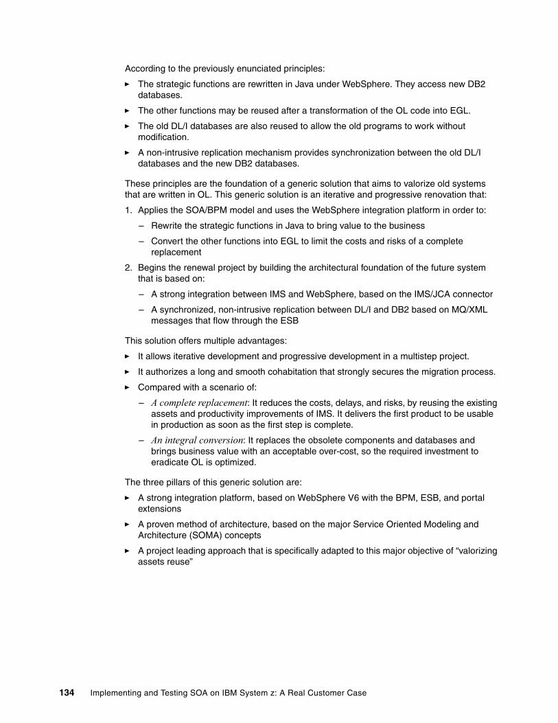
According to the previously enunciated principles:
� The strategic functions are rewritten in Java under WebSphere. They access new DB2 databases.
� The other functions may be reused after a transformation of the OL code into EGL.
� The old DL/I databases are also reused to allow the old programs to work without modification.
� A non-intrusive replication mechanism provides synchronization between the old DL/I databases and the new DB2 databases.
These principles are the foundation of a generic solution that aims to valorize old systems that are written in OL. This generic solution is an iterative and progressive renovation that:
1. Applies the SOA/BPM model and uses the WebSphere integration platform in order to:
– Rewrite the strategic functions in Java to bring value to the business
– Convert the other functions into EGL to limit the costs and risks of a complete replacement
2. Begins the renewal project by building the architectural foundation of the future system that is based on:
– A strong integration between IMS and WebSphere, based on the IMS/JCA connector
– A synchronized, non-intrusive replication between DL/I and DB2 based on MQ/XML messages that flow through the ESB
This solution offers multiple advantages:
� It allows iterative development and progressive development in a multistep project.
� It authorizes a long and smooth cohabitation that strongly secures the migration process.
� Compared with a scenario of:
– A complete replacement: It reduces the costs, delays, and risks, by reusing the existing assets and productivity improvements of IMS. It delivers the first product to be usable in production as soon as the first step is complete.
– An integral conversion: It replaces the obsolete components and databases and brings business value with an acceptable over-cost, so the required investment to eradicate OL is optimized.
The three pillars of this generic solution are:
� A strong integration platform, based on WebSphere V6 with the BPM, ESB, and portal extensions
� A proven method of architecture, based on the major Service Oriented Modeling and Architecture (SOMA) concepts
� A project leading approach that is specifically adapted to this major objective of “valorizing assets reuse”
134 Implementing and Testing SOA on IBM System z: A Real Customer Case
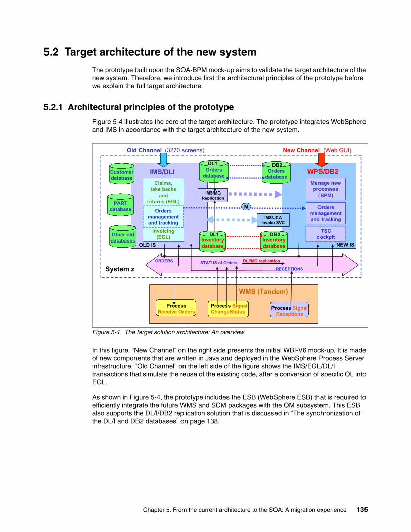
5.2 Target architecture of the new system
The prototype built upon the SOA-BPM mock-up aims to validate the target architecture of the new system. Therefore, we introduce first the architectural principles of the prototype before we explain the full target architecture.
5.2.1 Architectural principles of the prototype
Figure 5-4 illustrates the core of the target architecture. The prototype integrates WebSphere and IMS in accordance with the target architecture of the new system.
Figure 5-4 The target solution architecture: An overview
In this figure, “New Channel” on the right side presents the initial WBI-V6 mock-up. It is made of new components that are written in Java and deployed in the WebSphere Process Server infrastructure. “Old Channel” on the left side of the figure shows the IMS/EGL/DL/I transactions that simulate the reuse of the existing code, after a conversion of specific OL into EGL.
As shown in Figure 5-4, the prototype includes the ESB (WebSphere ESB) that is required to efficiently integrate the future WMS and SCM packages with the OM subsystem. This ESB also supports the DL/I/DB2 replication solution that is discussed in “The synchronization of the DL/I and DB2 databases” on page 138.
WPS/DB2
Process SignalChangeStatus
WMS (Tandem)
IMS/DLI
Process SignalReceptions
Inventorydatabase
Ordersdatabase
Customerdatabase
Ordersdatabase
PARTdatabase
Other olddatabases Inventory
database
DB2DL1
DL1 DB2
ProcessReceive Orders
IMS/JCAInvoke SVC
DLI/MQ replication
IMS/MQ Replication
ORDERS STATUS of OrdersRECEPTIONS
Manage new processes
(BPM)
Ordersmanagementand tracking
TSCcockpit
Claims,take backs
andreturns (EGL)
Invoicing(EGL)
System z
Ordersmanagementand tracking
Old Channel (3270 screens) New Channel (Web GUI)
M
OLD IS NEW IS
Chapter 5. From the current architecture to the SOA: A migration experience 135
The prototype builds the foundation of the new system by integration between WebSphere Process Server and IMS with the following main objectives:
� Secure the OM component of the old system, as soon as possible, by using an efficient mix between the build and the reuse options:
– Rewrite in BPEL and Java the Register_Orders_and_Tracking function and bring added value to the business. In the meantime, the solution benefits from the BPM solutions that are proven by the mock-up.
– Convert into EGL the Claims_TakeBack_and_Returns and Dealers_Invoicing functions. Reuse of these existing OL modules, which makes up about 65 percent of the code, allows reduced costs and limited risks.
� Allow for a long cohabitation and investment distributed over a long period of time.
This solution allows the customer to:
� Secure the Create_Order process, which is one of the more strategic functions of the OM subsystem
� Extend the architectural model that was previously validated by the SOA-BPM mock-up
� Integrate the old IMS/EGL application with the new WebSphere or Java system
� Run on a sysplex that provides the QOS required by the future system
This solution is efficient, fast responding, scalable, and fully secured. It can be extended to a worldly network of dealers through a business-oriented business-to-business (B2B) portal and a Web-service B2B gateway that is located in a secured firewall.
Therefore, this prototype creates a reference implementation:
� It proves the generic approach aiming to valorize the major OL applications.
� Compared to the first scenarios studied by the project team:
– A complete rewriting in Java: It reduces the costs, delays, and risks of a full replacement.
– An integral conversion into EGL: It brings business value and optimizes the investment that is required to eradicate OL in a complex system.
Claims_TakeBack_and_Returns function: The Claims_TakeBacks_and_Returns function allows dealers to take back useless parts to OEM. If their claims are accepted, they can return these parts to the warehouse.
136 Implementing and Testing SOA on IBM System z: A Real Customer Case
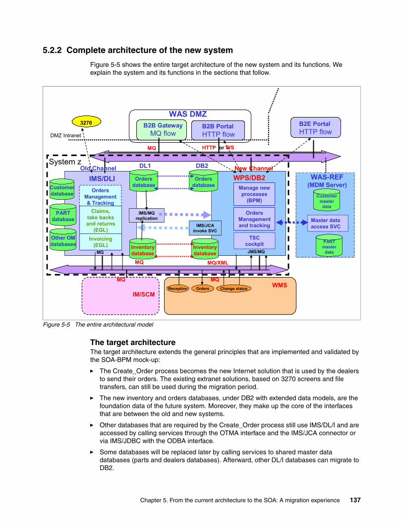
5.2.2 Complete architecture of the new system
Figure 5-5 shows the entire target architecture of the new system and its functions. We explain the system and its functions in the sections that follow.
Figure 5-5 The entire architectural model
The target architectureThe target architecture extends the general principles that are implemented and validated by the SOA-BPM mock-up:
� The Create_Order process becomes the new Internet solution that is used by the dealers to send their orders. The existing extranet solutions, based on 3270 screens and file transfers, can still be used during the migration period.
� The new inventory and orders databases, under DB2 with extended data models, are the foundation data of the future system. Moreover, they make up the core of the interfaces that are between the old and new systems.
� Other databases that are required by the Create_Order process still use IMS/DL/I and are accessed by calling services through the OTMA interface and the IMS/JCA connector or via IMS/JDBC with the ODBA interface.
� Some databases will be replaced later by calling services to shared master data databases (parts and dealers databases). Afterward, other DL/I databases can migrate to DB2.
DMZ Intranet
B2B PortalHTTP flow
B2B GatewayMQ flow
WAS DMZ
WMSIM/SCM
MQ
MQ HTTP or WS
Change statusOrdersReception
B2E PortalHTTP flow
WPS/DB2 WAS-REF (MDM Server)
IMS/DLI
Master dataaccess SVC
Inventorydatabase
OrdersdatabaseCustomer
database
PARTmaster
data
Ordersdatabase
PARTdatabase
Other OMdatabases Inventory
database
DB2DL1
JMS/MQMQ
IMS/JCAinvoke SVC
IMS/MQ replication
Customermaster
data
MQ MQ/XML
MQ
3270
OrdersManagement& Tracking
Claims,take backs and returns
(EGL)Invoicing
(EGL)
Manage new processes
(BPM)
OrdersManagement and tracking
TSCcockpit
Old Channel New ChannelSystem z
Chapter 5. From the current architecture to the SOA: A migration experience 137
� The valid orders that are received by the new channel are pushed into the old system. The urgent orders are also transmitted, via MQ/XML messages, to the WM subsystem.
� The updates of the two copies of the inventory and orders databases, the old DL/I/IMS and the new DB2, are synchronized by transactions that are activated via MQ/XML messages. This solution must be validated in the prototype.
� The management of the Claims_TakeBack_and_Returns process is unchanged and uses EGL/3270 IMS transactions. The screens that are used by the dealers are translated into Web pages and must be integrated into the B2B portal.
� Invoicing is always provided by the old system, even after a conversion into EGL.
� The Get_Order_Status process allows the dealers to follow up on their orders in real time. The orders database is updated via MQ by the Track_Order_Status process.
The synchronization of the DL/I and DB2 databasesTo answer to the business needs, several existing data models of the old system must be improved. For example, new data models for the inventory database need to be added and implemented under DB2. However, to reuse IMS transactions without any code modification, the existing DL/I databases must be kept. Therefore, the target architecture integrates two copies of the orders and inventory databases:
� The old IMS/DL/I databases, used by existing EGL programs� The new DB2 databases, used by new Java components
The technical solutions that are used to synchronize these two copies of the same data are generic and are based on the following mechanisms:
� The IMS/JCA connector, which is used by the Java components that invoke the IMS transactions, with the two phase-commit option
� The IMS/DL/I MQ replication function, which allows the interception of all the updates that are made on DL/I databases and provide MQ/XML messages that contain the modified data
One objective of the prototype is to evaluate these replication solutions.
138 Implementing and Testing SOA on IBM System z: A Real Customer Case
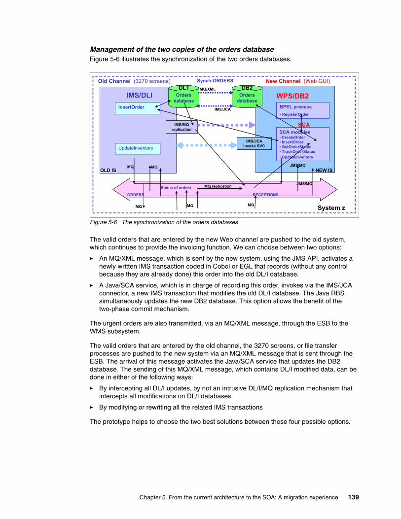
Management of the two copies of the orders database Figure 5-6 illustrates the synchronization of the two orders databases.
Figure 5-6 The synchronization of the orders databases
The valid orders that are entered by the new Web channel are pushed to the old system, which continues to provide the invoicing function. We can choose between two options:
� An MQ/XML message, which is sent by the new system, using the JMS API, activates a newly written IMS transaction coded in Cobol or EGL that records (without any control because they are already done) this order into the old DL/I database.
� A Java/SCA service, which is in charge of recording this order, invokes via the IMS/JCA connector, a new IMS transaction that modifies the old DL/I database. The Java RBS simultaneously updates the new DB2 database. This option allows the benefit of the two-phase commit mechanism.
The urgent orders are also transmitted, via an MQ/XML message, through the ESB to the WMS subsystem.
The valid orders that are entered by the old channel, the 3270 screens, or file transfer processes are pushed to the new system via an MQ/XML message that is sent through the ESB. The arrival of this message activates the Java/SCA service that updates the DB2 database. The sending of this MQ/XML message, which contains DL/I modified data, can be done in either of the following ways:
� By intercepting all DL/I updates, by not an intrusive DL/I/MQ replication mechanism that intercepts all modifications on DL/I databases
� By modifying or rewriting all the related IMS transactions
The prototype helps to choose the two best solutions between these four possible options.
WPS/DB2
MQ MQ
IMS/DLIBPEL process• RegisterOrder
SCA modules• CreateOrder• InsertOrder• GetOrderStatus• TrackOrderStatus• UpdateInventory
Ordersdatabase
MQ
SCA
Ordersdatabase
InsertOrder
UpdateInventory
DB2DL1
JMS/MQ
MQMQ
IMS/JCAinvoke SVC
MQ replication
IMS/MQ replication
ORDERS
Status of orders
RECEPTIONS
Synch-ORDERSMQ/XML
IMS/JCA
System z
JMS/MQ
Old Channel (3270 screens) New Channel (Web GUI)
OLD IS NEW IS
Chapter 5. From the current architecture to the SOA: A migration experience 139
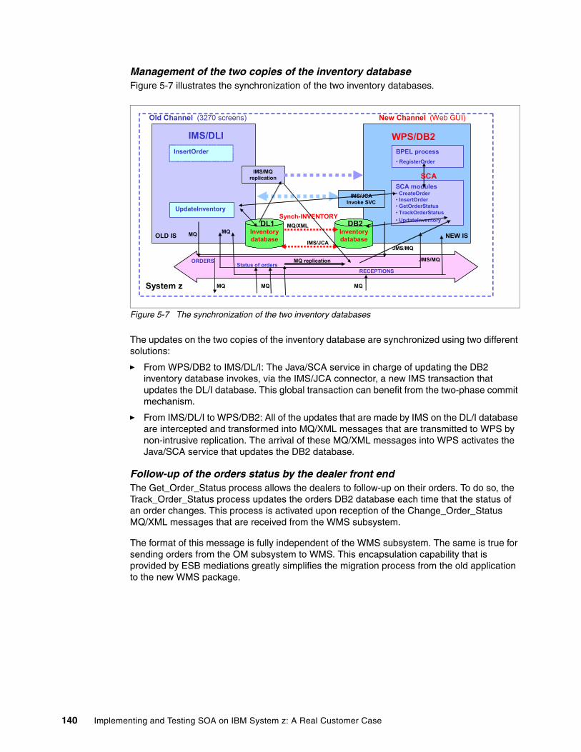
Management of the two copies of the inventory database Figure 5-7 illustrates the synchronization of the two inventory databases.
Figure 5-7 The synchronization of the two inventory databases
The updates on the two copies of the inventory database are synchronized using two different solutions:
� From WPS/DB2 to IMS/DL/I: The Java/SCA service in charge of updating the DB2 inventory database invokes, via the IMS/JCA connector, a new IMS transaction that updates the DL/I database. This global transaction can benefit from the two-phase commit mechanism.
� From IMS/DL/I to WPS/DB2: All of the updates that are made by IMS on the DL/I database are intercepted and transformed into MQ/XML messages that are transmitted to WPS by non-intrusive replication. The arrival of these MQ/XML messages into WPS activates the Java/SCA service that updates the DB2 database.
Follow-up of the orders status by the dealer front endThe Get_Order_Status process allows the dealers to follow-up on their orders. To do so, the Track_Order_Status process updates the orders DB2 database each time that the status of an order changes. This process is activated upon reception of the Change_Order_Status MQ/XML messages that are received from the WMS subsystem.
The format of this message is fully independent of the WMS subsystem. The same is true for sending orders from the OM subsystem to WMS. This encapsulation capability that is provided by ESB mediations greatly simplifies the migration process from the old application to the new WMS package.
WPS/DB2
MQ MQ
IMS/DLIBPEL process• RegisterOrder
SCA modules• CreateOrder• InsertOrder• GetOrderStatus• TrackOrderStatus• UpdateInventory
Inventorydatabase
Synch-INVENTORY
MQ
SCA
Inventorydatabase
InsertOrder
UpdateInventory
DL1 DB2MQ/XML
IMS/JCA
JMS/MQ
MQMQ
IMS/JCAInvoke SVC
MQ replication
IMS/MQ replication
ORDERSStatus of orders
RECEPTIONS
System z
JMS/MQ
Old Channel (3270 screens) New Channel (Web GUI)
OLD IS NEW IS
140 Implementing and Testing SOA on IBM System z: A Real Customer Case

Implementation of the main interfacesAll the interfaces between the new and the old systems are provided by exchanging messages through the WebSphere ESB:
� The synchronous exchanges (from the new system to the former system) use the IMS/JCA connector and therefore, benefit from the two-phase commit option.
� The asynchronous exchanges (from the former system to the new system) are made in MQ/JMS mode by XML messages.
� All exchanges between the OM and WMS subsystems are made in asynchronous mode, via MQ/JMS/XML messages.
Figure 5-8 illustrates the main exchanges from the new IS to the former IS.
Figure 5-8 The new IS to old IS major interfaces
The following interfaces need to be implemented:
� From the new OM subsystem to the former OM subsystem
The orders are received by the new system via JMS/MQ (B2B gateway) or Web-SVC (B2B portal). The update of the IMS/DL/I inventory database is made by a service call, using the IMS/JCA connector. The valid orders are also pushed into the old system by a service call, using IMS/JCA.
� From the new OM subsystem to the WMS subsystem
The urgent orders are transmitted from the OM subsystem to the WMS subsystem via an MQ/XML message. The status changes are signaled by the WMS subsystem, via an MQ/XML message that is sent to the OM subsystem. The receptions from the suppliers
WPS/DB2
Inventorydatabase
Synch-INVENTORY
Ordersdatabase
Customerdatabase Orders
database
PARTdatabase
Other RCdatabases
Inventorydatabase
DB2DL1
DL1 DB2
JMS/MQ
MQ JMS/MQMQ
IMS/JCAInvoke SVC
IMS/MQ Replication
ORDERSStatus of orders
RECEPTIONS
ORDERS
Ordersreceived by the
B2B gateway
Orders entered into the
B2B portal
Order tracking
System monitoring
Ordersreceived by CFT
Ordersreceived by the
3270 IHM
Synch-ORDERS
DLI/MQ Replication
System z
Manage new processes
(BPM)
Ordersmanagementand tracking
TSCcockpit
IMS/DLIOrders
managementand tracking
Claims,take backs and returns (EGL)
Invoicing(EGL)
OLD ISNEW IS
Chapter 5. From the current architecture to the SOA: A migration experience 141
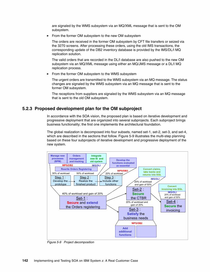
are signaled by the WMS subsystem via an MQ/XML message that is sent to the OM subsystem.
� From the former OM subsystem to the new OM subsystem
The orders are received in the former OM subsystem by CFT file transfers or seized via the 3270 screens. After processing these orders, using the old IMS transactions, the corresponding update of the DB2 inventory database is provided by the IMS/DL/I MQ replication solution.
The valid orders that are recorded in the DL/I database are also pushed to the new OM subsystem via an MQ/XML message using either an MQ/JMS message or a DL/I MQ replication process.
� From the former OM subsystem to the WMS subsystem
The urgent orders are transmitted to the WMS subsystem via an MQ message. The status changes are signaled by the WMS subsystem via an MQ message that is sent to the former OM subsystem.
The receptions from suppliers are signaled by the WMS subsystem via an MQ message that is sent to the old OM subsystem.
5.2.3 Proposed development plan for the OM subproject
In accordance with the SOA vision, the proposed plan is based on iterative development and progressive deployment that are organized into several subprojects. Each subproject brings business functionality; the first one implements the architectural foundation.
The global realization is decomposed into four subsets, named set-1, set-2, set-3, and set-4, which are described in the sections that follow. Figure 5-9 illustrates the multi-step planning based on these four subprojects of iterative development and progressive deployment of the new system.
Figure 5-9 Project decomposition
Set-1 : Secure and extend
the Orders registering
Set-2 : Secure
the CTBR
Set-3 : Satisfy the
business needs
Set-4 : Secure the
invoicing
Step 1 : Develop the
prototype
Step 2 : Realize the
finished product
Step 3 : Include other
functions
Integratenew IS and old system
Addadditionalfunctions
Develop thefunctions evaluated
as essentialRewrite Orders Registering
IMS/DLI
WPS/DB2
WPS/DB2
20% of workloadand gain of 50%
30% of workload
Convert claims,take backs and
returns into EGL
IMS/DLI
Convertinvoicing into EGL
IMS/DLI20% of workloadand gain of 50%
50% of workload 20% of workload
20% of workload and gain of 20%
40% of workload and gain of 20%
Manage new processes
(BPM)
Ordersmanagementand tracking
WPS/DB2
142 Implementing and Testing SOA on IBM System z: A Real Customer Case
The four subprojects are explained as follows:
1. Set-1 secures and completes the Order_Registering function. It offers dealers an ergonomic Web interface that is usable for the Orders_Registering and follow-up functions, as well as for the Claims_TakeBack_and_Returns function from the dealer’s side.
2. Set-2 secures the Claims_TakeBack_and_Returns component by conversion of the OL code to EGL. The transformation of the old 3270 screens to a Web-based interface is an option that still needs to be validated at this stage.
3. Set-3 implements new databases or extends existing ones. It also realizes modifications of the processes and services that are required to implement the functional extensions that are requested by the business.
The modification of the processes is made at the BPEL level or by new business rules. The modification of the services that are called by these processes requires modification or rewriting of some components, for example Java services or IMS/EGL transactions. The cockpit that is used by the TSC agents to pilot the new system is realized in this stage and is included in the B2E portal.
4. Set-4 converts the Dealers_Invoicing OL code to EGL, making the required adaptations.
Parallel working teams may realize set-2 and set-3 independently.
Initial development of a prototypeThe objective of set-1 is to secure the Orders_Registering function and to set up the architectural foundation that is required for the whole project. Within set-1, the realization of the Order_Registering components is made in accordance with the same principles and is divided into three steps.
� The first step builds the prototype as an extension of the SOA-BPM WBI V6 mock-up. We first develop the prototype that implements all the architectural elements of the target but with a limited functional scope. It deliberately simplifies the processes, the business rules, and the complexity of the code that are required to implement the services.
� The second and third steps enrich this prototype to produce the first production deliverable of the project that aims to secure and extend the Orders_Registering function, which is the strategic function of the OM subsystem.
The result of set-1 can be used in production as a new Internet channel for orders entry and follow-up. The coding of the prototype can start as soon as its specifications are written. As soon the development is ended, the prototype is integrated with the former system. The tests and the integration within the acceptance system begin immediately after the end of the development phase.
Enrichment of the initial developmentThe Secure_and_Extend_Orders_Registering deliverable product is produced by functional enrichment of the prototype that was previously realized.
The specifications of the target Order_Registering components are written during the coding and testing of the prototype. The coding of new components that correspond to business specifications is made in parallel. As soon as a component is specified, the coding begins. When the component works, we integrate it into the prototype.
The WS-BPEL specifications of the Create_Order process and the components that implement the services in the prototype are gradually replaced by the final components. At each delivery, the new subsystem is completely revalidated.
Chapter 5. From the current architecture to the SOA: A migration experience 143
By the end of the coding and test phase, the new components have been widely tested in their context of deployment. Because integration with the former system has already been partially tested with the prototype, the final integration tests are noticeably shortened.
Principles of migrationThe fundamental principle is to allow for a progressive migration, with a smooth cohabitation between the new and former system during a possible long period of time. This migration can begin at the end of set-1. The resulting product provides an additional Internet channel for the orders entry and their follow-up, although the dealers can send orders either in the former system or in the new one, providing a progressive migration path.
At first and during an indefinite period of time, the new system insures only the entry of the orders and the follow-up of their status by the dealers. The two other functions, the Claims_TakeBack_and_Returns and the Dealer_ Invoicing, stay in the former system. The new system can be seen as an Internet channel that has been added to the old system.
Except for the initial load of the new inventory and orders DB2 databases, there is no need for additional mechanisms for master data loading. The interfaces with the other information systems stay in the former system. The SCM subsystem can directly use the new DB2 inventory database, for example, to know the availability of remaining parts.
For the realization of set-2 and set-4, the same principles are used for progressive migration between the former and new systems. For example, the conversion of the OL code into EGL for the Claims_TakeBack_and_Returns function will preserve the old DL/I databases as well as the 3270 existing interfaces. The only exception is for the screens that are used by dealers that must be converted into a Web interface.
For the first objective of set-2, which is the eradication of OL, the 3270 screens that are used only by OEM agents are transformed into Web pages later (both Web and 3270 interfaces coexist in the same subsystem). If necessary, other DL/I databases will be migrated under DB2, with a synchronization mechanism if this one is required by the old, existing code.
This progressive migration, which allows simultaneous operations in the old and new systems, is a major advantage of the proposed development plan.
144 Implementing and Testing SOA on IBM System z: A Real Customer Case
Appendix A. Performance tests
In this appendix, we provide performance numbers that we obtained from tests that were performed early in the definition of the architecture. These tests were done on an IBM System p environment on AIX to give us a basic understanding about resource consumption. The numbers that we obtained confirmed that the use of the WebSphere environment was good compared to the use of an integration package. It was then decided that we should develop the WebSphere approach.
In this appendix, we provide a few performance indicators. Different architectures and different platforms were tested. The results demonstrated that good performances were obtained with the SOA-BPM architecture as described in Figure A-1.
The heavy loading of the WMS simulator partition is due to the design that we chose for the Signal_Change_Status process. As explained in 2.3.5, “Implementation of the WMS simulator” on page 82, the process is implemented as a long-running Business Process Execution Language (BPEL) process. This design was chosen because it allows for quick development of the simulator. This component has been coded only for the performance tests and has no value for the project. Nevertheless this measure is interesting because it shows that a long-running process, which saves its context at each interrupt, is more expensive than a short-running process, which saves nothing.
In this test environment, 6,780 Create_Order transactions were simulated. They were injected by 60 users during one hour. Therefore, the workload was a simulation of two transactions per second. The response time of the transaction given by the injector is 0.12 seconds.
A
Important: The numbers that are provided in this appendix are specific to our environment. Therefore they cannot be used as a basis for an interpolation for other environments. It is important to remember to consider the performance aspects in an architecture project.
© Copyright IBM Corp. 2007. All rights reserved. 145
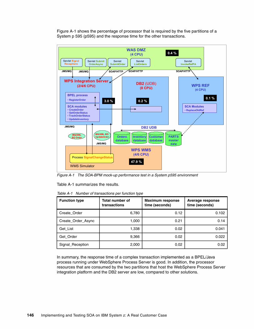
Figure A-1 shows the percentage of processor that is required by the five partitions of a System p 595 (p595) and the response time for the other transactions.
Figure A-1 The SOA-BPM mock-up performance test in a System p595 environment
Table A-1 summarizes the results.
Table A-1 Number of transactions per function type
In summary, the response time of a complex transaction implemented as a BPEL/Java process running under WebSphere Process Server is good. In addition, the processor resources that are consumed by the two partitions that host the WebSphere Process Server integration platform and the DB2 server are low, compared to other solutions.
Function type Total number of transactions
Maximum response time (seconds)
Average response time (seconds)
Create_Order 6,780 0.12 0.102
Create_Order_Async 1,000 0.21 0.14
Get_List 1,338 0.02 0.041
Get_Order 9,366 0.02 0.022
Signal_Reception 2,000 0.02 0.02
JMS/MQ SOAP/HTTP
WPS REF(4 CPU)
SOAP/HTTP
Process SignalChangeStatus
ServletSubmitOrder
ServletListOrders
ServletInvokeRefPA
Servlet SubmitOrderAsync
MQ/XMLBO Order
MQ/XML:BO UpdateOrder
WAS DMZ(4 CPU)
WPS WMS(4/6 CPU)
JMS/MQ
JMS/MQ
Servlet SignalReceptions
BPEL process• RegisterOrder
SCA modules• CreateOrder• GetOrderStatus• TrackOrderStatus• UpdateInventory
SCA Modules• ReplaceOldRef
0.4 %
3.0 % 0.2 %
47.9 %
0.1 %
WMS Simulator
WPS Integration Server(2/4/6 CPU) DB2 (UDB)
(8 CPU)
Inventorydatabase
Ordersdatabase
Customerdatabase
PARTSmaster
data
DB2 UDB
JMS/MQ SOAP/HTTP
146 Implementing and Testing SOA on IBM System z: A Real Customer Case
Other tests that were done with a heavier charge have confirmed good scalability and stability of the architecture. Table A-2 shows the results of three additional tests in which only the Create_Order BPEL/Java process is invoked.
Table A-2 Number of Create_Order processes, function of transactions per second
Table A-3 provides the processor consumption per partition, depending on the number of transactions.
Table A-3 Processor consumption per partition and function of number of transactions
From these tests, we see that:
� The response time is excellent, lower than 0.2 seconds.
� The processor resource that is consumed by the System p595 partition, which hosts the WebSphere Process Server, remains low.
� The proposed solution is highly scalable.
Additional tests were done to measure the effect of the number of processors that were allocated to the WebSphere Process Server partition. These test showed that a small configuration can support 30 transactions per second with a response time of 0.8 sec. with two processors, and 50 transactions per second with a response time of 0.27 sec. with four processors. Another test, simulating 50 transactions per second, showed that 500 part items can be processed in one second.
Even if the real Create_Order process implemented by the future customer system is more complex than the BPEL and Java transaction described by the mock-up, all these results prove that the proposed integration architecture responds to the quality of services that are required by the future customer application framework. The SOA-BPM mock-up testing demonstrated that the full WebSphere solution requires a relatively light configuration.
Transactions per second
Number of users
Elapsed time Number of Create_Order processes
Maximum response time (seconds)
Average response time (seconds)
10 100 23 mn 35 sec. 12,000 0.16 0.109
20 100 13 mn 38 sec. 12,000 0.15 0.107
50 250 14 mn 38 sec. 30,000 0.20 0.128
Transactions per second
P1: WAS DMZ P2: WPS integration server
P3: DB2 P4: WPS REF P5: WMS simulator
10 0.4 2.8 0.1 0.1 32.2
20 1.2 9.0 0.1 0.1 27.2
50 2.9 19 0.6 0.1 43.2
Appendix A. Performance tests 147

148 Implementing and Testing SOA on IBM System z: A Real Customer Case
ronyms
3GL Third-generation Programming Language
4GL Fourth-generation programming Language
ABAP Advanced Business Application Programming
ABS Application Business Services
AIX Advanced Interactive eXecutive
API application programming interface
B2B business to business
B2C business to consumers
B2E business to employee
BAPI Business Application Programming Interface
BPEL Business Process Execution Language
BPM business process management
CBE Common Business Event
CBS Core Business Services
CEI Common Event Infrastructure
DAO Data Access Object
DL/I Data Language/I
DMS Dealer Management System
DMZ demilitarized zone
EA enterprise architecture
EBS Existing Business Services
EDI Electronic Data Interchange
EGL Enterprise Generation Language
EJB Enterprise JavaBean
ERP Enterprise Resource Planning
ESB Enterprise Service Bus
ESCON Enterprise Systems Connection
ETL Extract Transfer and Load
GUI graphical user interface
HTTP Hypertext Transfer Protocol
IBM International Business Machines Corporation
IDOC Intermediate Document
IFL Integrated Facilities for Linux
IM Inventory Management
IMS information management system
ISV independent software vendor
Abbreviations and ac
© Copyright IBM Corp. 2007. All rights reserved.
IT information technology
ITSO International Technical Support Organization
J2EE Java 2 Platform, Enterprise Edition
JDBC Java Database Connectivity
JMS Java Message Service
JSF Java Server Faces
JSP JavaServer Page
KPI key performance indicator
LAN local area network
LDAP Lightweight Directory Access Protocol
LPAR logical partition
MDB message-driven bean
MDM Master Data Management
MDS Master Data Services
MM Material Management
MQ Message Queue
ODBC Open Database Connectivity
OEM Original Equipment Manufacturer
OL obsolete language
OM Orders Management
OSA Open Systems Adapter
PL/I Programming Language/I
PR/SM™ Processor Resource/Systems Manager™
PSSC Products and Solutions Support Center
QOS quality of service
RBS Reusable Business Services
SC Supply Chain
SCA Service Component Architecture
SCM Supply Chain Management
SD Sales and Distribution
SDO Service Data Object
SDP Software Delivery Platform
SOA service-oriented architecture
SOAP Originally stood for Simple Object Access Protocol, and lately Service Oriented-Architecture Protocol
SOMA Service-Oriented Modeling and Architecture
149
SQL Structured Query Language
SQLJ Structured Query Language for Java
TCP/IP Transmission Control Protocol/Internet Protocol
TSO Time Sharing Options
VSAM Virtual Storage Access Method
WESB WebSphere Enterprise Service Bus
WM Warehouse Management
WMS Warehouse Management Subsystem
WS-BPEL Web Services Business process Execution Language
WSDL Web Services Description Language
XFDL Extensible Forms Description Language
XML Extensible Markup Language
zAAP IBM System z Application Assist Processor
150 Implementing and Testing SOA on IBM System z: A Real Customer Case
Related publications
The publications listed in this section are considered particularly suitable for a more detailed discussion of the topics covered in this book.
IBM RedbooksFor information about ordering these publications, see “How to get IBM Redbooks” on page 152. Note that some of the documents that are referenced here may be available in softcopy only.
� Building Composite Applications, SG24-7367
� Connect WebSphere Service Oriented Middleware to SAP, SG24-7220
� Patterns: SOA Design using WebSphere Message Broker and WebSphere ESB, SG24-7369
� Patterns: SOA Foundation - Business Process Management Scenario, SG24-7234
� Patterns: SOA Foundation Service Creation Scenario, SG24-7240
� Production Topologies for WebSphere Process Server and WebSphere ESB V6, SG24-7413
� SOA Transition Scenarios for the IBM z/OS Platform, SG24-7331
� The Role of IBM System z In the Design of a Service Oriented Architecture, REDP-4190
� The Value of the IBM System z and z/OS in Service-Oriented Architecture, REDP-4152
� z/OS Getting Started: WebSphere Process Server and WebSphere Enterprise Service Bus V6, SG24-7378
� z/OS Technical Overview: WebSphere Process Server and WebSphere Enterprise Service Bus, REDP-4196
Online resourcesThese Web sites are also relevant as further information sources:
� Atos Origin
http://www.atosorigin.com/en-us/
� Exploring key facts about business process management with IBM WebSphere software
ftp://ftp.software.ibm.com/software/websphere/pdf/NEW_BPM_WhitePaper_WSW11279-USEN-00.pdf
� IBM Design Centers
http://www-03.ibm.com/systems/services/designcenter/
� IBM developerWorks document regarding the Service Component Architecture
http://www-128.ibm.com/developerworks/webservices/library/specification/ws-sca/
� IBM PSSC Customer Center
http://www-5.ibm.com/fr/events/centers/montpellier/index_en.html
© Copyright IBM Corp. 2007. All rights reserved. 151
� IBM Service Oriented Modeling and Architecture methodology (SOMA)
http://www-128.ibm.com/developerworks/library/ws-soa-design1/
� Techdoc WP100653, “WebSphere z/OS V6 -- WSC Sample ND Configuration”
http://www-03.ibm.com/support/techdocs/atsmastr.nsf/WebIndex/WP100653
� Techdoc WP100878, “WebSphere Process Server/WebSphere Enterprise Service Bus v6.0.1 for z/OS: Network Deployment Configuration Lab”
http://www-03.ibm.com/support/techdocs/atsmastr.nsf/WebIndex/WP100878
� System z Application Assist Processor (zAAP)
http://www-03.ibm.com/systems/z/zaap/
How to get IBM RedbooksYou can search for, view, or download IBM Redbooks, Redpapers, Hints and Tips, draft publications and Additional materials, as well as order hardcopy Redbooks or CD-ROMs, at this Web site:
ibm.com/redbooks
Help from IBMIBM Support and downloads
ibm.com/support
IBM Global Services
ibm.com/services
152 Implementing and Testing SOA on IBM System z: A Real Customer Case
Index
AABS (Application Business Service) 5, 45API 39, 82, 100, 105, 139application
components 78composite 2design 73model 2silos model 2transversal 2vertical 2
Application Business Service (ABS) 5, 45Apply_Business_Rules 81, 110architectural model 12architecture 11, 25, 55, 59, 68, 76
BBAPI 14, 30, 64, 69BPEL (Business Process Execution Language) 9, 35, 75, 112BPM (business process management) 3, 16, 26–27, 33, 80, 134builder 124bus
BPC.Cellname.Bus 96business choreographer bus 97CEI bus 97CommonEventInfrastructure_Bus 96SCA application bus 97SCA system bus 97SCA-APPLICATION-CellName-Bus 96SCA-SYSTEM-CellName-Bus 96
Business Activity Monitoring 110, 116business measures editor 116business object 113business process 2
choreography 5Business Process Choreographer 94Business Process Design 110Business Process Engine 110Business Process Execution Language (BPEL) 9, 35, 75, 112business process management (BPM) 3, 16, 26–27, 80, 134
engine 33Business Process Modeling 110Business Rule Manager 114business rules 12, 111
CCBE (Common Business Event) 117CBS (Core Business Services) 5CEI 93, 95–96
© Copyright IBM Corp. 2007. All rights reserved.
augment file 96CFT files transfer 142choreographer 93CICS 9, 32, 128Claims_TakeBack_and_Returns function 136COBOL 129cohabitation 16, 28, 127, 144command
Augment 92zWebSphere Process ServerConfig 92
Common Business Event (CBE) 117Complete_Order process 111Control_and_register process 75Core Business Services (CBS) 5Create_Order BPM model 30Create_Order module 76Create_Order process 18, 30, 51, 57, 65, 74, 79, 102
DDAO (Direct Access Object) 9, 79DB2 12, 24, 39, 66, 90, 92, 110, 127, 138, 146Direct Access Object (DAO) 9, 79DL/I 12, 23, 35, 45, 56, 127, 134
EEA (enterprise architecture) 6EBS (Existing Business Services) 14Eclipse Open Source 129EGL (Enterprise Generation Language) 14, 127EGL-based debugging 129EJB (Enterprise JavaBean) 9, 38, 65, 68, 79enterprise architecture (EA) 6Enterprise Generation Language (EGL) 14, 127Enterprise JavaBean (EJB) 9, 38, 65, 68, 79Enterprise Service Bus (ESB) 3, 9, 16, 33–34, 53, 134ESB (Enterprise Service Bus) 3, 9, 16, 33–34, 53, 134ETL (Extract Transfer and Load) 3Existing Business Services (EBS) 14Extensible Forms Description Language (XFDL) 118Extensible Markup Language (XML) 7Extract Transfer and Load (ETL) 3
Ggateway 5Get_Order_Status module 76Get_Order_Status process 120graphical user interface (GUI) 3, 113, 121, 124GUI (graphical user interface) 3, 113, 121, 124
HHiperSockets 45, 48
153
IIBM Rational Software Delivery Platform 129IDOC 69IFL (Integrated Facility for Linux) 48IMS 9, 13, 23, 29, 44, 53, 127IMS/JCA connector 127, 134Integrated Facility for Linux (IFL) 48
JJ2EE 6, 17, 33, 69, 77, 84, 87, 100, 109, 129J2EE simulator 52Java 9, 78, 124, 129, 146JavaServer Faces (JSF) 129JavaServer Pages (JSP) 124JDBC 39, 129, 137JMS 39, 52, 87, 90
API 105binding 100SCA binding 87
JSF (JavaServer Faces) 129JSP (JavaServer Pages) 124JSR168-compliant portlets 124
Kkey performance indicator (KPI) 112, 116KPI (key performance indicator) 112, 116
LLDAP 38, 114Linux 48long-running process 113
MManage_Order_Component process 80Master Data Manager (MDM) 3, 69, 77Master Data Services (MDS) 3MDB (message-driven bean) 38, 68MDM (Master Data Manager) 3, 69, 77MDS (Master Data Services) 3message-driven bean (MDB) 38, 68Microsoft.NET 6mock-up 12model 124modeling
bottom-up 8top-down 8
MQ link 99
Nnaming convention 91–92, 97
Oobsolete language (OL) 23ODBA 137ODBC 129OL (obsolete language) 23
OM (Orders Management) 17, 51Orders Management (OM) 17, 51OTMA interface 137
Ppattern 4, 26portal 3, 15–16, 33, 120, 134Portal Document Manager 120portlet 111, 115, 118, 120
development 124Mytasks 114
prototype 12
QQOS 17, 40, 50, 136queue manager 99
RRational 128Rational Application Developer 115RBS (Reusable Business Services) 3, 8, 27, 38Receive_incoming_Orders process 75receiver channel 99Redbooks Web site 152
Contact us ixreference implementation 136Register_Order process 80, 86, 105, 110response file 92, 95Reusable Business Services (RBS) 3, 8, 27, 38role 38, 111, 115, 120
SSAP 14, 26, 51, 62
BAPI 14IDOC 14
SCA (Service Component Architecture) 9, 34–35, 51, 87, 100, 111schema generator 116SCM (Supply Chain Management) 17, 21, 50SDO 34, 36Service Component Architecture (SCA) 9, 34–35, 51, 87, 111
binding 100Service Oriented Modeling and Architecture (SOMA) 9, 16, 26, 134service-oriented architecture (SOA) 6short-running process 113sibDDLgenerator script 97SIBus 78, 83, 93, 96, 98, 102Signal_Change_Status process 105silos problematic 2SOA (service-oriented architecture) 6SOA-BPM model 51SOAP 87SOMA (Service Oriented Modeling and Architecture) 9, 16, 26, 134SQLJ 39, 79, 87stateless session bean, SCA binding 87
154 Implementing and Testing SOA on IBM System z: A Real Customer Case
Supply Chain 21Supply Chain Management (SCM) 17, 21, 50Supplying and Inventory Management 21System z platform 40, 89
TTCP/IP ports 91to-do-list 111, 114Track_Order_status module 76Track_the_status_of_orders process 75Transfer_this_order process 75transversal applications 2
UUNIX 48Update_Inventory module 76
VValidate_Order process 110vertical applications 2
WWarehouse Management (WMS) 17, 50, 88Web service 52
SCA binding 87Web Services Business Process Execution Language (WS-BPEL) 6, 13, 33, 38, 51, 80, 143Web Services Description Language (WSDL) 6, 9, 27, 36, 38, 80, 119WebSphere Application Server 27, 33, 53, 64, 75, 83, 88, 91WebSphere Business Integration 47WebSphere Business Modeler 34, 110, 112WebSphere Business Monitor 34, 110WebSphere ESB 91, 127, 135WebSphere Integration Developer 34, 106, 110, 114WebSphere MQ 129WebSphere MQ Version 6 90WebSphere Portal 110, 114, 116, 118, 120WebSphere Portlet Factory 124WebSphere Process integration server 59WebSphere Process Server 90, 110
BPM Engine 113integration server 76
Web-SVC 69, 141WMS (Warehouse Management) 17, 50, 88Work_items 111, 114Workplace Forms 110, 118
Designer 119Viewer 118
WS-BPEL (Web Services Business Process Execution Language) 6, 13, 33, 38, 51, 80, 143WSDL (Web Services Description Language) 6, 9, 27, 38, 80, 119
Port Type 36
XXFDL (Extensible Forms Description Language) 118XForms extension 118XForms standard 118–119XML (Extensible Markup Language) 7, 38, 119, 134
Zz/OS 83, 89zAAP 41zSMPInstall script 91zWebSphere Process ServerConfig script 92
Index 155

156 Implementing and Testing SOA on IBM System z: A Real Customer Case

(0.2”spine)0.17”<
->0.473”
90<->
249 pages
Implem
enting and Testing SOA on IBM System
z: A Real Customer Case
Implem
enting and Testing SOA on IBM
System z: A Real Custom
er Case
Implem
enting and Testing SOA on IBM
System z: A Real Custom
er Case
Implem
enting and Testing SOA on IBM System
z: A Real Customer Case

Implem
enting and Testing SOA on IBM
System z: A Real Custom
er Case
Implem
enting and Testing SOA on IBM
System z: A Real Custom
er Case

®
SG24-7502-00 ISBN 0738488755
INTERNATIONAL TECHNICALSUPPORTORGANIZATION
BUILDING TECHNICAL INFORMATION BASED ON PRACTICAL EXPERIENCE
IBM Redbooks are developed by the IBM International Technical Support Organization. Experts from IBM, Customers and Partners from around the world create timely technical information based on realistic scenarios. Specific recommendations are provided to help you implement IT solutions more effectively in your environment.
For more information:ibm.com/redbooks
®
Implementing and Testing SOA on IBM System zA Real Customer Case
Using SOA to add business value to existing systems
Rejuvenating old applications for a modernized infrastructure
Understanding the cohabitation and migration process
Service-oriented architecture (SOA) is one of the most important topics on the agenda of any IT person. SOA involves a new vision of how to design, develop, and manage applications. It also has new requirements when building an architecture for the underlying infrastructure.
This IBM Redbooks publication is the result of a project managed in the IBM European Design Center, based in Montpellier, France. The scope of the project involved helping a major worldwide customer in the automotive industry to validate and justify an SOA implementation. In particular, the customer wanted to add new business values to work with its partners, by adding new data models. It also wanted to modernize an infrastructure, by adding new Internet interfaces. The customer faced the need to eradicate an obsolete programming language. Furthermore, it wanted to build a smooth migration path, with as few risks and costs as possible.
The thought, planning, and architecture of the new system, which included integration of the SOA concepts, was built by the customer with the participation of Atos Origin, a leading international IT services provider. The existing customer IT infrastructure was already built around UNIX systems, IBM System z, non-IBM clusters, SAP solutions, 3270 screens, IMS-DL/I databases, and specific code. SOA was the right solution to connect this existing environment to new components using Java, Web services, and DB2 in particular.
This book explores the business needs and the architectural choices that were faced by the customer. It describes the mock-ups and prototypes, provides performance numbers that were used to validate the decisions, and explains how they were implemented. It also suggests a generic and riskless solution to eradicate the obsolete programming language.
Back cover