from map to model: the development of an urban information system
TRANSCRIPT

From map to model: the development of an urban information system
Alan Day, Centre for Advanced Studies in Architecture, University of
Bath, Bath BA2 7AY, UK
The use of three-dimensional computer models for urban planning and design is discussed with particular reference to a recently completed model
of the City of Bath. Problems in making such models generally available are identified and a solution, which is particularly appropriate for
nonexpert users, is proposed.
Keywords: planning, computer-aided design, urban models
1 Enlot, d The City in Maps: Urban Mapping to 1900, The Brit- ish Library, London (1987)
1 The utility of maps
T he characteristics of the contemporary map are so familiar that
they can easily be taken for granted. The map is a symbolic
representation of the world drawn to an accurate scale, using a set
of uniform symbols. A high degree of abstraction is employed in order to
reduce the amount of information to manageable proportions and this is
then presented in a structured way which allows the map to be read easily.
However, maps, and in particular urban maps, were not always presented
in this way. Early maps, particularly during the medieval period, were
aerial views which showed the geometric form and appearance of the city
as well as its street layout (Figure 1). Accuracy was often sacrificed in
order to ensure that all the finest buildings and monuments were shown
and the artistic and symbolic qualities of the work were at least as
important as its objective status 1. The introduction of improved surveying
techniques in the Renaissance facilitated the production of increasingly
accurate maps and these new maps, which presented the city as a plan
projection, superseded the aerial views. As they were increasingly used
for military purposes and to record land transactions, accuracy became
366 0142-694X/94/030366-19 © 1994 Butterworth-Heinemann Ltd

"r .
I
Urban information system 367

critical and by 1739 the move to accurate plans of cities was so well
advanced that Louis Bretez's stunning plan of Paris, covering 20 sheets,
(Figure 2) was not particularly well received by the Parisian press 2.
Although aerial views continued to be fairly common in Europe through-
out the 18th century their use was restricted to recording picturesque
towns or presenting new developments, as in Baumeister 's views of
Karlsruhe in 1739.
Accurate surveying, standardized sets of symbols, and, from the late 19th
century, cheap offset lithographic printing resulted in the 2D map
becoming the standard way of representing cities. There is no denying the
usefulness of these maps, be it for navigation, planning new develop-
ments, or mapping spatially related data, but the paradigm of the map is
now so powerful that it tends to blind us to other forms of representation.
The map is a product of the printing press and its cheapness and
portability have been central to its success.
With the advent of computers, new technology has been brought to bear
on the map and the resulting geographic information systems (GIS) have
taken the map and added analytic tools. These systems accept the existing
paradigm and have linked it with database technology in order to give the
map intelligence. Sophisticated though these systems are they have simply
accepted the map as the way of representing urban form without fully
considering its strengths and weaknesses. Accuracy, consistency and
portability are all strengths but consistency has been achieved by reducing
the complexities of the real world through the exclusion of information,
and in particular by eliminating three-dimensional form. Contours have
been developed to overcome this problem when representing landscape,
but there is no equivalent in the urban context.
2 Ibid. p 56
This 18th century trade-off between accuracy and representation is no
longer relevant as it is now possible to have the best of both worlds
through the use of three-dimensional computer modelling. This preserves
the accuracy of an original survey while representing land and building
form realistically. Over the past 30 years computer-aided design (CAD)
systems have been developed which allow the user to create three-
dimensional models of buildings which can be as accurate as necessary
and, once created, can be viewed from any position. As hardware and
software have become increasingly powerful the scale of these 3D models
has increased, from individual buildings to urban blocks and now to whole
cities. There are clearly advantages in bringing GIS and CAD technology
together in order to shift GIS from being map-based to being model-
based. The map was the result of a need married to a particular
368 Design Studies Voi 15 No 3 July 1994
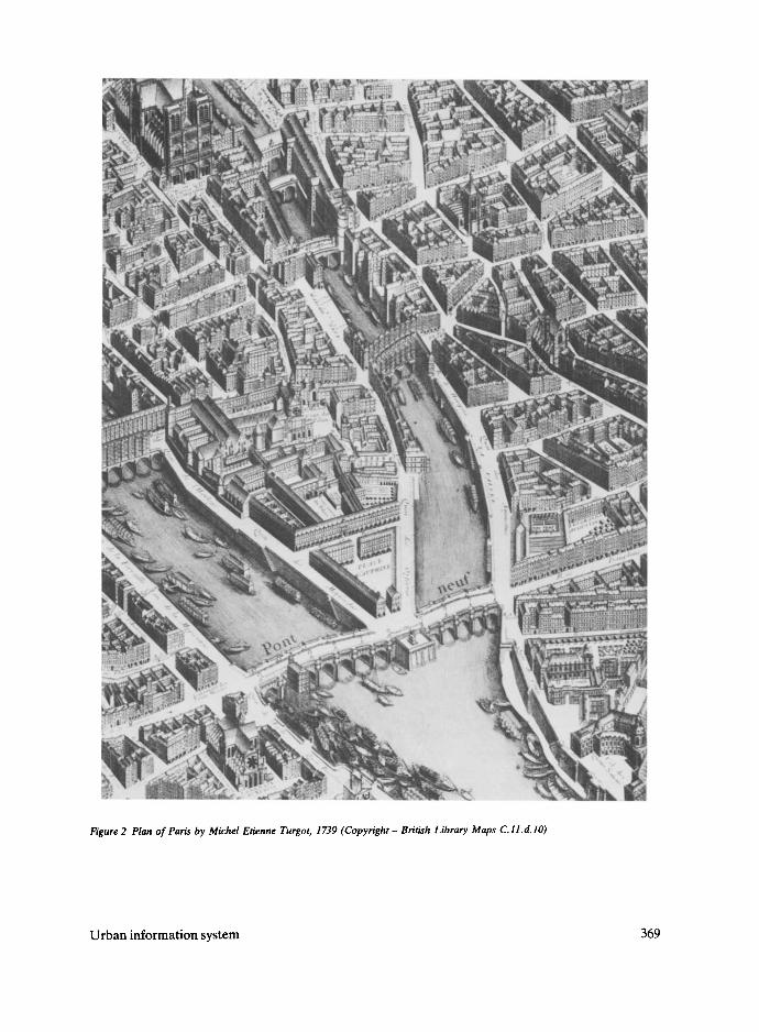
Figure 2 Plan of Paris by Michel Etienne Turgot, 1739 (Copyright - British Library Maps C.11.d.lO)
Urban information system 369
technology; now that the technology has changed the map can take its
place as just one level of representation within a much richer environ-
ment.
2 Existing urban models Early examples, such as the Skidmore Owings and Merrill model of
Chicago, 3 were just an assembly of simple blocks but increasingly
sophisticated urban models have been built since. The Architecture and
Building Aids Computer Unit at Strathclyde University (ABACUS) have
two, an extensive model of Glasgow and a smaller, more detailed model
of Edinburgh Old Town. This is intended to assist the Old Town Trust
with the conservation and economic regeneration of the historic core of
the city, while the Glasgow model is designed to provide GIS functionality and offer a way of integrating various types of urban information 4.
The most direct use for urban models is as part of the planning process.
Hall 5 reports on tests carried out on the use of computer visualization in
development control where three projects were modelled and the results
used for discussions between the applicant and planners. He comments on
the advantages to lay people of this kind of visualization and on its
usefulness to professionals engaged in the design process. The objective
status of the computer material was thought to be particularly advan-
tageous. As Hall puts it, 'It is suggested that a central component of the
argument for the use of computer visualisation in planning control is that
it can be seen to be independent of the positions of all the negotiating parties '6.
3 Mitchell, W J Computer-Aided Architectural Design Van Nos- trand Reinhold, New York (1977) pp 264-265 4 Grant, M 'Urban GIS - The application of the information technologies to urban manage- ment', in J A Pov~ll and R Day (ads) Informing Technologies for Construction, Civil engineering and Transport Brunel/SERC, Ux- bridge, UK, (1993) 10P 195-199 5 Hall, A C 'The use of computer visualisetion in planning control' Town Planning Review, Vo164 No 2 (1993) 193-211 6 Ibid. p 206 7 Merchant, A N 'Expert sys- tem: a design methodology' Computers, Environment and Urban Systems Vo116 No 1 (1992) 21-41
By combining computer modelling with expert systems new kinds of
design tools can be created. Merchant 7 discusses the development of an
Urban Design Expert System which was created to provide advice on the
design of a public space. The system initially offers the designer assistance
by offering a range of appropriate visual precedents and, when the scheme
is complete, the system can be used for evaluation with evaluation criteria
themselves being varied by the designer. The scheme design is carried out within a CAD package and the geometrical information it contains
provides much of the data .for analysis by the expert system. At the moment such systems are fairly primitive and work best with constrained
problems, but they indicate a way in which intelligence can be added to
urban models which is complementary to the kind of analytical tools that GIS systems provide for maps.
The issues involved in the creation and use of large 3D representations of
370 Design Studies Vol 15 No 3 July 1994
urban areas have been investigated over the past two years in Bath where
a model of the entire Georgian city has recently been completed.
Experience has been gained on the effectiveness of various ways of
constructing such models and on the opportunities and constraints
inherent in their use.
3 Development and conservation in Bath In most historic towns, including Bath, there is particular concern about
how new should relate to old. The strongest feelings often have to do with
the appearance of modern buildings and, in particular, how they relate to
existing buildings within a historic setting. When new buildings are
proposed there are often difficulties in understanding what is intended
and in assessing the impact of the proposal on its surroundings. There is a
desire for public debate, but that debate can very easily be stifled by
difficulties in understanding what is proposed because of problems in
reading traditional architectural drawings. Bitter experience has shown
that slick draughtsmanship and a carefully contrived perspective view can
all too easily fool a planning committee into thinking that a proposal is
appropriate only to find, when the building is complete, that it intrudes on
its surroundings in ways that were never anticipated. In order to address
this problem two things are required, an accurate and easily understood
representation of the proposal, and a presentation technique that is
objective and not completely under the control of the applicant.
4 Visualizing change In order to address this problem, some 25 years ago Bath Preservation
Trust commissioned a wooden model of the city as a vehicle for
considering the implications of new developments. The intention was to
alter the model in order to show change, but the expense and difficulty of
doing this meant that it was never used in this way. However, had it been
used, its scale of 1:500 would have meant that it would only have been
useful for considering change at an urban scale and would not have been
particularly appropriate for detailed consideration of the small-scale
changes that constitute the bulk of planning applications.
A computer model, on the other hand, is inherently flexible and so change
can be accommodated and detail added in order to visualize even very
minor alterations. As computers are being used increasingly for
architectural design it is not unusual for a planning application to be accompanied by drawings derived from a CAD model. However, such
presentations can be as deceptive as their hand-drawn counterparts as the
views are carefully selected and the surroundings may not have been modelled particularly accurately. The Bath computer model is designed to
Urban information system 371
address this problem. When planning permission for a new building is
sought the design can be included in the urban model thus providing an
accurate context and allowing views to be set up from any position, and by
any party. Also, parts of the model can be supplied to architects who are
working on sites in the city, thus giving them immediate access to an
accurate representation of their buiiding's immediate context.
4.1 The construction of the Bath computer model The 3D computer model includes the whole of the Georgian city, most
commercial and business activities and a considerable portion of the city's
residential fabric (Figure 3). The model was constructed using aerial
photogrammetry, a technique which uses pairs of photographs which are
viewed in stereo, allowing the operator to see the subject in three
dimensions. A photogrammetric plotter connected to a personal compu-
ter is used, and when the operator digitizes a point on a building its x, y
and z co-ordinates are entered directly into a CAD package running on
the PC. In Bath, survey photographs taken by Ordnance Survey in 1991
were used with any buildings constructed since that date being entered
manually from the architects' drawings. One of the great benefits of
employing aerial photogrammetry is that fieldwork can be kept to a
minimum thus allowing the construction of the model to proceed rapidly.
Also, as the photographs are taken looking vertically downwards, build-
ings that are difficult to get to, or are on private land, can easily be
surveyed. The external form of any building can be determined accurately
and the roof geometry and details, such as parapets and chimney stacks,
fully represented. The result is a model which is particularly convincing
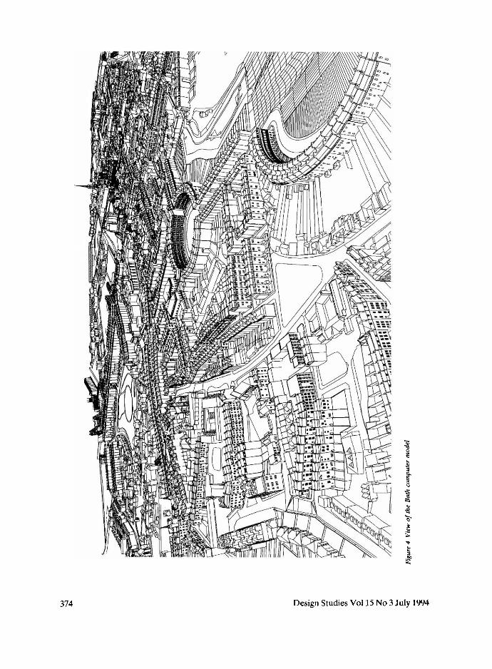
from above and which accurately represents the grain of the city (Figure
4). The weakness of the system is the capital cost of the equipment,
upwards of £30 000 for a basic stereo plotter, and the paucity of
elevational information, something that is inevitable when the photo-
graphs are taken from above. However, this deficiency can easily be
rectified by taking additional photographs where more detail is required,
either as single images, or as stereo pairs to facilitate the modelling of a
facade in depth.
In order to introduce a precise scale when constructing a photogrammetric
model actual dimensions between known points on the photograph are
required. These control points can be surveyed conventionally but, as this
is expensive and time-consuming, spot heights on 1:1250 Ordnance
Survey maps were used. Each city block was treated as a separate CAD
model and these were located relative to one another using their National
Grid co-ordinates. Depending on size and complexity, each block took
between three and ten days for a skilled operator to construct and no
372 Design Studies Vol 15 No 3 July 1994

, . .', . .~
Figure 3 Plan showing the extent o f the Bath computer model
significant inaccuracies were experienced when the blocks were assembled
into the complete urban model. The whole model comprises some 150
urban blocks, occupies 60 Mb of disk space in Au toCAD .dwg format.
and cost about £100 000 to produce over an 18 month period. A 3D
terrain model was also constructed to show the countryside for 10 km
around Bath to ensure that any views taken from the city centre include
the rural skyline which is so important to Bath's setting. As it was
important for architects' CAD models to be incorporated into the urban
Urban information system 373
~t
374 Design Studies Vol 15 No 3 July 1994

model it was decided to use industry-standard CAD software with well
developed data exchange procedures and so Au toCAD Release 12
running on 486-based personal computers was used to construct the urban
blocks with the renderings and animation sequences being carded out in
Autodesk 3D Studio running on a PC, or in Wavefront Advanced
Visualiser running on a Silicon Graphics workstation.
4 . 2 Using the model To date, the main use of the model has been for development control. In
one example a school wanted to build a new sports hall on a sensitive
sloping site in front of one of Bath's most elegant crescents. Planning
permission had been refused previously and the city council planners
recommended that the model be used by newly appointed architects to
test a number of different strategies on the site. Three different schemes
were modelled and a series of views and animations set up for each. In
Bath the planning committee is especially concerned about the impact of
new developments on long distance views and so views of the site were set
up from precise locations on the other side of the valley for each of the
proposed schemes.
Two meetings, each lasting about 90 minutes, were held with the planners
and client's architects to consider the results of the computer visualiza-
tion. All parties agreed how helpful the technique was and it emerged that
the long distance views were deemed to be of little importance when
compared with close-up views and the impact of the new building on its
immediate neighbours. The result of the meetings was that all those
present agreed that one of the solutions showed particular promise and
this was then developed to a full planning application.
4.3 Issues in use At the moment the Bath model comprises some 150 submodels which can
each be accessed separately or combined as required. This process is
carried out via a reference drawing which shows the outline of each block
as a single polyline with the Au toCAD drawing name indicated. Indi-
vidual urban blocks can be loaded by clicking on the area within the
appropriate polyline, or the whole model assembled automatically.
Currently, when the model is being used for development control and a
view or animation sequence is required, the planners have to contact the
university and ask for the proposed building to be modelled and the
images created. Although this system works well enough it constrains the
use of the model by placing it at one remove from the end-user.
The reasons for this are both economic and technical. The quantity of data
Urban information system 375

contained in an urban model is large and a considerable amount of
computer power is required for its manipulation. This is expensive for an
organization where computer-aided design is a luxury rather than an
essential working tool and where staff lack training and experience in its
use. Even a planner with considerable enthusiasm for computing would
find it difficult to gain sufficient experience in the range of CAD and
visualization software that is used to create views of the Bath model. If
one wants the end-user to have access to the system then their needs have
to be addressed directly and, assuming that the model is going to be
maintained and updated by experts, these needs are relatively simple.
They want to be able to navigate around the model, set up views and
animation sequences, print out the results, and import and export urban
blocks for use by designers. To be economic such a facility should be
capable of being delivered on a standard personal computer using a
graphical user interface, such as Microsoft Windows.
5 Theproblem ofsize With a model of the size being discussed here, such simple requirements
can be problematic. Even navigation around the Bath model is difficult.
In Au toCAD, with the whole model loaded, it takes about 20 minutes to
regenerate the screen after moving the viewing position, and rendering a
single view of the entire city in 3D Studio can take over 50 hours. Even
using Wavefront Advanced Visualiser on a powerful Silicon Graphics
workstation a single view can take several hours to render. There are, of
course, strategies that can be adopted to reduce the amount of data that
has to be manipulated, for example, by excluding all the information that
is outside the view and structuring the data so that the level of detail
present in any part of the model is related to its distance from the viewing
position. For fast rendering it also makes sense to reduce the number of
faces in the model and increase the amount of texture mapping, but such a
strategy results in a model that is unsatisfactory for design purposes. The
Bath model is intended to be used as a design aid and therefore must be
accurate and have sufficient geometric detail to be realistic. A simple
rectangular prism with scanned photographs applied to its faces to
represent a building may be quite satisfactory for an interactive computer
demonstration but is of limited use as a design tool, particularly when
dealing with the intricacies of a historic city.
Although the power of computers is increasing rapidly in relation to cost,
the amount of information that makes up an urban model also tends to
increase as detail is added over time. So, it is unlikely that it will be
practical to ' run' a large urban model with anything approaching interac-
tive navigation on a personal computer within the next five years at least.
376 Design Studies Vol 15 No 3 July 1994
8 The terms hypertext and hypermedia were coined by Ted Nelson in the 1970s and refer to a new media form in which material from a variety of sources is linked together in a flexible and open- ended way. One of the first hyperlext applications, was Ap- ple's Hypercard.
If one simplifies the model, for example by having a number of different
versions of each urban block, then one can navigate by using the simplest
level of detail and only switch to the more complex level when the viewing
position is established. In the Bath model there are currently three levels
of detail: the outline polyline, a simple block model and the fully detailed
geometric model. Although such a strategy works well enough, it is a
device to overcome a technical deficiency and can be awkward for the
user. What they want is to have the full model presented on the computer
screen and to be able to move around it interactively. Clearly this is very
difficult to achieve while maintaining realistic modelling and rendering
and, even if one adopts strategies such as automatic scene culling and
level-of-detail selection, interactive navigation will only be possible on the
most powerful computers.
However, by being selective in terms of what one renders one can bring
rendering times down to minutes rather than hours and it is therefore
possible to build up multiple views of the model in a relatively short time.
If sufficient views are rendered, from known positions then one can move
between these views quite quickly and thus simulate a form of interactive
navigation. Although there are constraints to this approach, if sufficient
views are rendered a reasonable degree of interaction can be achieved
without the need to switch between various levels of detail. The disadvan-
tage of using views of the model, in the form of bitmapped pictures, is that
the pictures lose all the intelligence that is available in the CAD model
where attribute data can be assigned to any object. This allows the user to
select an object on the screen and, as the system knows what it is, a link
can be made to an external application, such as a database. This is a core
feature of geographic information systems, and if one can bring this kind
of intelligence back into bitmapped pictures then both navigation and
object selection can be achieved through the pictures without the need to
run the CAD model at all. With the Bath model this has been achieved by
programming Au toCAD to export a data file along with each bitmapped
picture which identifies each object in the view by specifying the area it
occupies in the picture. When this area, or 'button' , is selected on the
picture a link can be made to another picture, or to an external
application, thus re-introducing some of the intelligence that existed in the
original model.
The urban model should not be thought of as a single entity but rather a
collection of computer files which need to be browsed and selected
according to the needs of the user. As one has pictures with object buttons
already identified there are advantages in using a hypermedia system 8 to
make the necessary links as the very essence of hypermedia is the ability
Urban information system 377
9 Davis, H C, Hall, W, Heath, I, Hill, G and Wilklns, R 'Towards an integrated information en- vironment with open hypermedia systems' in D Lucarella, J Nanard, M Nanard, and P Paoli- nl (eds) The Proceedir~gs of the ACM Conference on Hypertext ECHT '92, ACM, Milano (1992) pp 181-190
to move between various kinds of data in a seamless and interactive way.
In order to achieve this, use is being made of some recently developed
software, Microcosm, from the Department of Electronics and Computer
Science at the University of Southampton.
6 Microcosm Microcosm 9 is designed to allow the user to browse through large bodies
of multimedia material by following links from one place to another. It
consists of an open message passing system combined with a number of
viewers and filters. Viewers are programs that can display various formats
of documents, including pictures, sound and video, and they communicate
with the filters to establish what active areas exist in a particular
document. When a selection is made, for example by clicking on a
building in one of the pictures, the user activates a link which may be of a
number of types. Some go directly to another piece of information, such
as a picture or document, while others offers choices, perhaps based on a
keyword search made through a range of documents.
When linked to a palette of simple tools, this allows the user to navigate
around the model by moving quickly from picture to picture and to set up
views or animation sequences for subsequent rendering. As the system
knows the co-ordinates of each object in three-dimensional space one can
select a camera and viewing position simply by clicking on two points in a
picture, or indeed across a range of pictures. These pictures need not be
limited to views of the model as maps and drawings can also be included in
order to aid object selection.
As Microcosm offers a way of linking objects in the model with other
kinds of information it opens up the possibility of using the model as a way
of organizing large amounts of information about the city in order to
create an urban information system in parallel with the visualization
model. This could range from text and photographs recording a building's
history, through social statistics derived from the census, to data gener-
ated by an energy modelling package. Microcosm was originally designed
to handle links between text document but it has now been developed to
handle all digital media, including sound and video. It offers a number of
advantages over other hypermedia systems which may be summarized as
follows:
No mark-up required in documents All the information concerning
links is held in a linkbase and not in the document itself. This means
that documents that are held on read-only media, such as a CD-ROM,
can still be marked up.
378 Design Studies Vol 15 No 3 July 1994

• Connectivity to other applications It is possible to make links that
dispatch other programs with a given dataset as a Microcosm viewer.
This means that a user can access a document that was created by
another application, such as a word processor or spreadsheet, and
work on it within that application. For example, one could have a link
that would launch Au toCAD, read in a drawing, and allow the user to
edit it directly.
• Wide range of link types In most hypermedia systems links have
specific source and destination anchors. Microcosm supports such
specific links, but also supports more general links. Links can have a
fixed end point, but may be followed from any point where a given
object (such as a specific text string) occurs within a document or
specified set of documents. This means that it is possible to create a
single link to a piece of reference material, which may then be
followed wherever the specified source selection occurs without
having to re-make the link at every possible source point. This results
in a considerable reduction in authoring effort compared to traditional
hypermedia systems.
• Open architecture Microcosm consists of a number of independent
processes which communicate using an open message format 1°. Mak-
ing a viewer is simply a matter of programming an application to send
these messages to the system, something which can be done with a few
lines of code. Microcosm's architecture and message system are open
so it is possible to distribute Microcosm functionality across different
machines on a network, even where the machines themselves have
differing architectures.
10 Fountain, AM, Hall, W, Heath, I and Davis, HC 'MICROCOSM: an open model for hypermedie with dynamic link- ing', in A Rlzk, N Streltz and J Andre (eds) Hypertext: Con- cepts, Systems and Applications. The Proceedings of The Euro- pean Conference on Hypertext, Cambridge University Press (1990) 11 u, z, Davis, H C and Hall, W 'Hypermedia links end in- formation retrievaJ' Proceedings of the 14th British Computer Society Research Colloquium on Information Retrieval, Lancaster University (1992)
It is important to stress that Microcosm is not a database, it is a link
service and multimedia navigation system n. Microcosm does not hold
documents, these are simply computer files which remain in their original
form. Microcosm holds attributes for these documents, and links between
documents. Users may navigate by making queries from the document
management system in a similar way that an SQL query is made from a
relational database, but there is a much larger range of navigational
techniques available. Microcosm does not make any requirement for data
to be structured or formatted in any particular way, nor does it dictate the
attributes that must be held for any link or document. These may be user
defined in every instance. The result is a system with much greater
flexibility and greater ease of navigation than is available from most
hypermedia or database systems.
7 Developing the Bath method Urban models of the kind discussed here are usually constructed on
Urban information system 379
powerful computers but have to be delivered on more basic machines to
users who may have limited computing experience. These machines, even
if they are well-specified 486 PCs, will not be able to cope with the full
urban model and therefore a strategy is being devised to use a networked
solution where all the intensive graphics processing is carried out on a
central machine with the results exported to the delivery machines for
viewing.
The software being developed to achieve this is based on Microcosm
running under both Unix and Microsoft Windows. The expensive CAD
and rendering software need only run on one machine with the client
machines using delivery software which can be made available at low cost.
This has the advantage of allowing an interface to be designed specifically
for the unskilled user independently of the CAD software that created the
model. As the model will reside on one machine it can be maintained and
updated by a single skilled operator thus ensuring a high degree of data
integrity. The set of pictures used for navigating the model, along with
their associated Microcosm buttons, can be automatically re-rendered
each week thus ensuring that users are always presented with an up-to-
date representation of the model.
8 The planning information system Currently under development is a computer-based planning information
system which will take the visualization capabilities that have already been
developed and link them to a series of databases. One will give specific
guidance to prospective planning applicants on matters which should be
considered when submitting a planning application, including illustrations
of current best practice selected by the development control officers. A
second database will contain a comprehensive record, in text and pictures,
of previous planning decisions which illustrate why particular decisions
were reached, This will be useful to the public and to development control
officers who aim at achieving consistency in their decision making. Built
into the system will be a feedback mechanism which will allow the public
to browse through current planning applications, see critical ones visual-
ized in the urban model, and offer their comments for entry into the database. This will widen the range of views that are received by the
officers and committee members.
9 Conclusions Large 3D computer models are becoming increasingly popular for urban planning and design. They provide a level of realism that can open up the
planning process to public scrutiny and allow strategies for the future to be
380 Design Studies Vol 15 No 3 July 1994
judged more effectively. Also, once created, such models can be used in
other ways as their legibility makes them ideal for accessing a database of
information about a city and for co-ordinating information that is
currently held separately. By linking visualization models to applications
which model other kinds of data, such as social statistics, energy-use
patterns or traffic flows, they can be used to present this information in
ways which make it more easily communicated and hence understood.
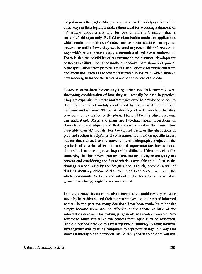
There is also the possibility of reconstructing the historical development
of the city as illustrated in the model of medieval Bath shown in Figure 5.
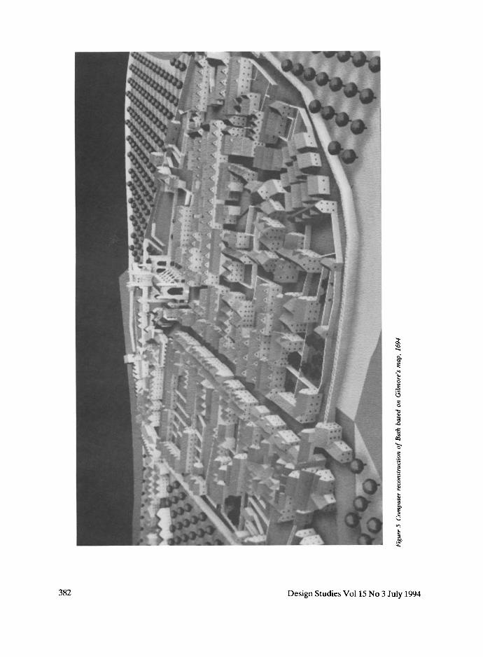
More speculative urban proposals may also be offered for public comment
and discussion, such as the scheme illustrated in Figure 6, which shows a
new mooring basin for the River Avon in the centre of the city.
However, enthusiasm for creating large urban models is currently over-
shadowing consideration of how they will actually be used in practice.
They are expensive to create and strategies must be developed to ensure
that their use is not unduly constrained by the current limitations of
hardware and software. The great advantage of such models is that they
provide a representation of the physical form of the city which everyone
can understand. Maps and plans are two-dimensional projections of
three-dimensional objects and that abstraction makes them much less
accessible than 3D models. For the trained designer the abstraction of
plan and section is helpful as it concentrates the mind on specific issues,
but for those unused to the conventions of orthographic projection the
synthesis of a series of two-dimensional representations into a three-
dimensional form can prove impossibly difficult. Urban models offer
something that has never been available before, a way of analysing the
present and considering the future which is available to all. Just as the
drawing is a tool used by the designer and, as such, becomes a way of
thinking about a problem, so the urban model can become a way for the
whole community to focus and articulate its thoughts on how urban
growth and change might be accommodated.
In a democracy the decisions about how a city should develop must be
made by its residents, and their representatives, on the basis of informed
choice. In the past too many decisions have been made by minorities
simply because there was no effective public debate as little of the
information necessary for making judgements was readily available. Any technique which can make this process more open is to be welcomed. Those described here do this by using new technology to bring informa-
tion together and by using computers to represent change in a way that
makes it intelligible to nonspecialists. Although such techniques will not,
Urban information system 381
~5
382 Design Studies Vol 15 No 3 July 1994
td
Urban information system 383

of themselves, guarantee that the cities of the future will be better than
those we have today they will at least ensure that the information required
to facilitate a more open debate is widely available.
384 Design Studies Vol 15 No 3 July 1994