from intro pages
TRANSCRIPT
1
1. INTRODUCTION
1.1 TITLE:
“Study of parameter affecting variation in diameter of driven plate of clutch”
1.2 EXPLAINATION OF TITLE:
During the manufacturing of driven plate, there is some variation occurs in produced driven
plate. The cause of this variation are parameters that are subject to study. Variation comes
in dimensions of driven plate. Variations like changing in outer diameter of driven plate,
distance between two holes of driven plate, burred surface and etc. During manufacturing
process, they inspects the product after every operation to check the dimension of product,
that should come in the range of designed dimension and also met to the given clearances
or allowances. If inspected driven plate not meet the real designed dimensions, than the
product is scrap. That raw material, labour work, input time- all are failed.
1.3 OBJECTIVES:
Objective of doing this bunch of work on this problem is following,
To reduce the occurrence of variation in production.
To reduce the rejection of lot and reduction in scrap.
To increase the quality of product by producing direct finish product without any variations
in dimensions.
To reduce the cost of inspection and also reduce the wastage of labour work.
Our other objective is to increase our skills and knowledge. By taking the part in industry
to solve their problem and want to experience the environment of industry, aware to
industry work plans, ultimately our objective is to get exposure to industrial management,
their environment and at last want to get exposure of industry.
1.4 AIM:
Our ultimate goal is to reduce variation in outer diameter (OD) after blanking and piercing
operation of driven plate during manufacturing.
2
2. INTRODUCTION OF INDUSTRY
SETCO AUTOMOTIVE LTD
Vadodara Godhra highway, KALOL – 388 330
They at SETCO Automotive place their customer’s need for exceptional service and
responsiveness at the top of their service agenda. Through an ever-expanding network, they
assist and provide support to their customers with a focus on total customer satisfaction.
They conduct training programs for vehicle manufacturers, their dealers and distributors,
on the mechanics of their clutch settings and maintenance. They recently initiated Service
Meets to garner critical customer feedback, assimilate best service practices and stay
updated on current market trends in the field.
Growth and change are a constant in any organization. As SETCO strive to become bigger
they would like to emphasize on excellence and tradition in the organization and build a
synergistic work ethic. Harnessing the passion of an employee is critical towards value
addition. Employee satisfaction through training and investments in better facilities is a
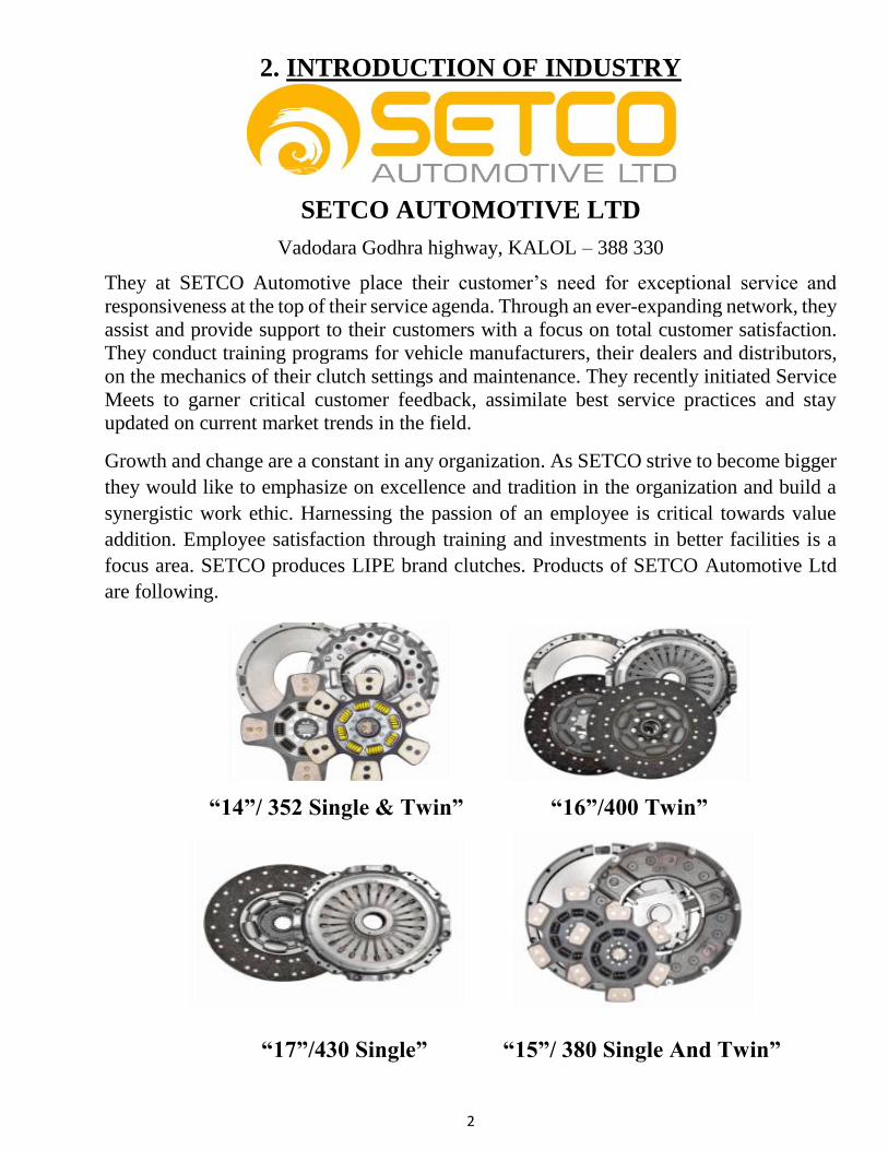
focus area. SETCO produces LIPE brand clutches. Products of SETCO Automotive Ltd
are following.
“14”/ 352 Single & Twin” “16”/400 Twin”
“17”/430 Single” “15”/ 380 Single And Twin”
3
3. DETAILED DISCRIPTION OF PROBLEM
We worked to solve the problem of outer diameter variation in DRIVEN PLATE. This
driven plate is assembled in “14”/ 352 Single & Twin” Clutch. There is biggest problem
occurred in assembly of clutch production.
Following is the total detail of driven plate design and manufacturing process.
3.1 DESIGN:
Part No: C019-L1739l
Part Name: Automatic Clutch Ceramic 14” Driven Plate
Material: 80C6 (IS 2507)
MS02 CRCA HRC 26±2
Thickness: 2.5 mm
Process: Parts blanks to be cold flattening and stress relieved to maintain 22 HRC
minimum.
Outer Diameter of driven plate: 352 mm
Surface Treatment: Phosphating (after complete operations)
3.2 Material properties:
Properties of C80 grade cold rolled annealed steel strips Chemical composition by weight:
Chemical Content (%)
Carbon 0.75 - 0.85%
Manganese 0.60 - 0.90%
Silicon 0.0-0.35%
Sulfur 0.025%
Phosphorous 0.025%
This grade is similar to 80c6 of IS2507 of 1975 & C1080.
3.3 Physical properties:
Hardness is annealed condition 200Hv Max
Yield strength 290 N/MM2
Elongation 25% Minimum
Tensile strength 640N/mm2
Surface bright and free from any detrimental surface defect
Edges Clean slit
This material is cold rolling closed annealing (CRCA) processed.
4
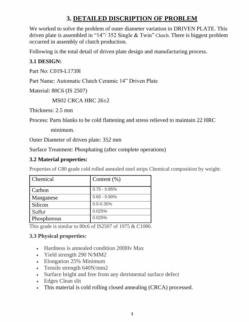
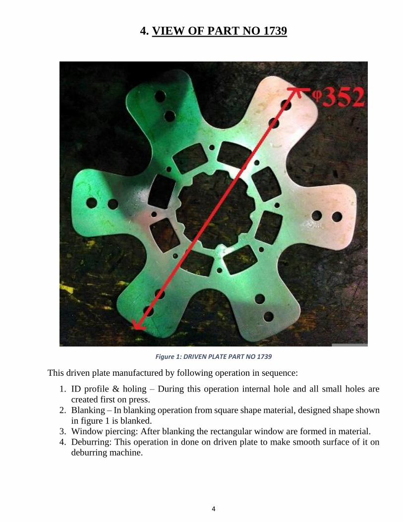
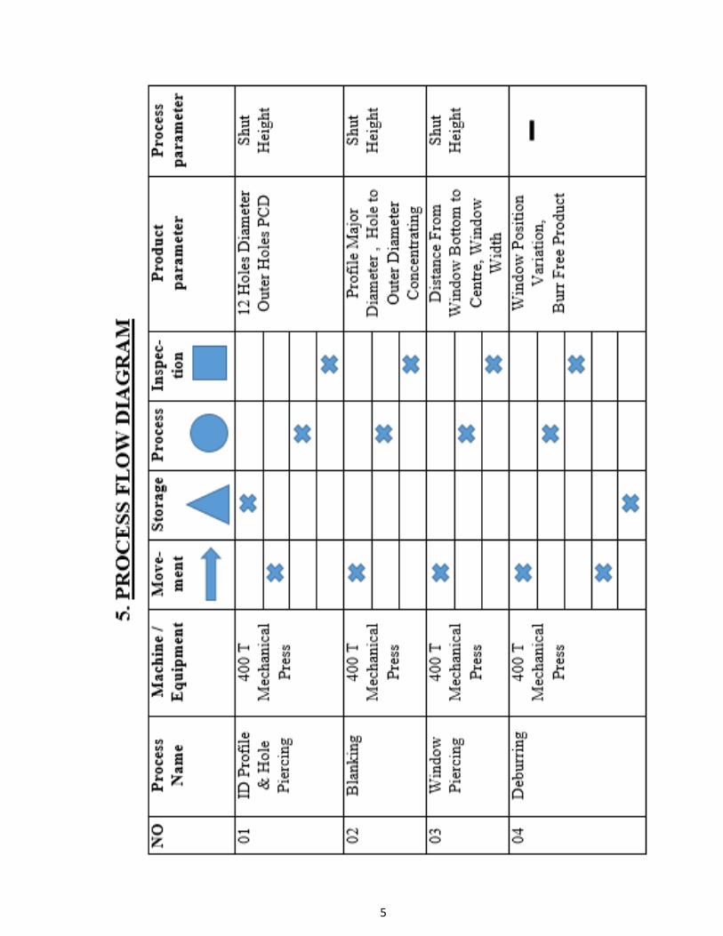
4. VIEW OF PART NO 1739
Figure 1: DRIVEN PLATE PART NO 1739
This driven plate manufactured by following operation in sequence:
1. ID profile & holing – During this operation internal hole and all small holes are
created first on press.
2. Blanking – In blanking operation from square shape material, designed shape shown
in figure 1 is blanked.
3. Window piercing: After blanking the rectangular window are formed in material.
4. Deburring: This operation in done on driven plate to make smooth surface of it on
deburring machine.
5
6
6. Literature Review
6.1 Sheet Metal Forming:
Sheet metal forming, involves operation such as cutting, drawing, spinning etc on sheets.
Sheet metal forming involves predominantly tensile forces, compared to bulk forming,
which involve compressive forces. Due to tensile stress, sheets may undergo localized
deformation followed by cracking. Sheets are rolled products, which have thickness less
than 6mm. Sheet metal operations involve work pieces with large surface area to thickness
ratio. Blanks are cut from sheets. These blanks are subsequently subjected to one or more
sheet forming operations in order to get the finished component. Sheet metal forming is
widely used for producing wide range of products starting from household vessels to
aerospace parts, to automobile or aircraft bodies. Final shape is obtained by applying
tensile, shear or combination of forces and stretching or shrinking the sheet metal blanks.
Part No-1739 Automatic Clutch Ceramic 14” Driven Plate is manufacture by sheet metal
forming processes like blanking, window piercing, holing, punching, shearing etc on
mechanical press.
6.2 Shearing:
Shearing is the process of cutting off of sheets using die & punch. Applying shear stress
along the thickness of the sheet. Shearing happens by severe plastic deformation locally
followed by fracture which propagates deeper into the thickness of the blank. The clearance
between the die and punch is an important parameter which decides the shape of the
sheared edge. Large clearance leads to rounded edge. The edge has distortion and has burr.
The shearing load is also higher for large clearance for harder material and larger sheet
thickness larger clearance is required. Generally, clearance can vary between 2% to 8% of
the sheet thickness. Shear zone width depends on the speed of punch motion. Larger speed
leads to narrow shear zone, with smooth shear surface and vice versa. Shearing a blank
involves plastic deformation due to shear stress. Therefore, the force required for shearing
is theoretically equal to the shear strength of blank material. Due to friction between blank
and tool, the actual force required is always greater than the shear strength. Variation of
punch force during shearing process is shown below. The maximum force required on the
punch for shearing can be empirically given as:
F max = 0.7tL
Where, ‘t’ is blank thickness and ‘L’ is the length of the sheared edge.
7
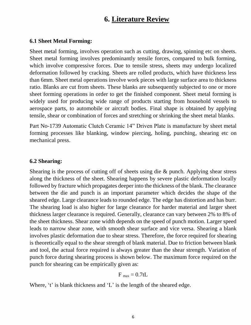
6.2.1 Shearing Zone Geometry:
Figure 2: Stages of shearing operation
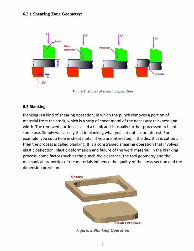
6.3 Blanking:
Blanking is a kind of shearing operation, in which the punch removes a portion of
material from the stock, which is a strip of sheet metal of the necessary thickness and
width. The removed portion is called a blank and is usually further processed to be of
some use. Simply we can say that in blanking what you cut out is our interest. For
example: you cut a hole in sheet metal, if you are interested in the disc that is cut out,
then the process is called blanking. It is a constrained shearing operation that involves
elastic deflection, plastic deformation and failure of the work material. In the blanking
process, some factors such as the punch-die clearance, the tool geometry and the
mechanical properties of the materials influence the quality of the cross-section and the
dimension precision.
Figure: 3 Blanking Operation
8
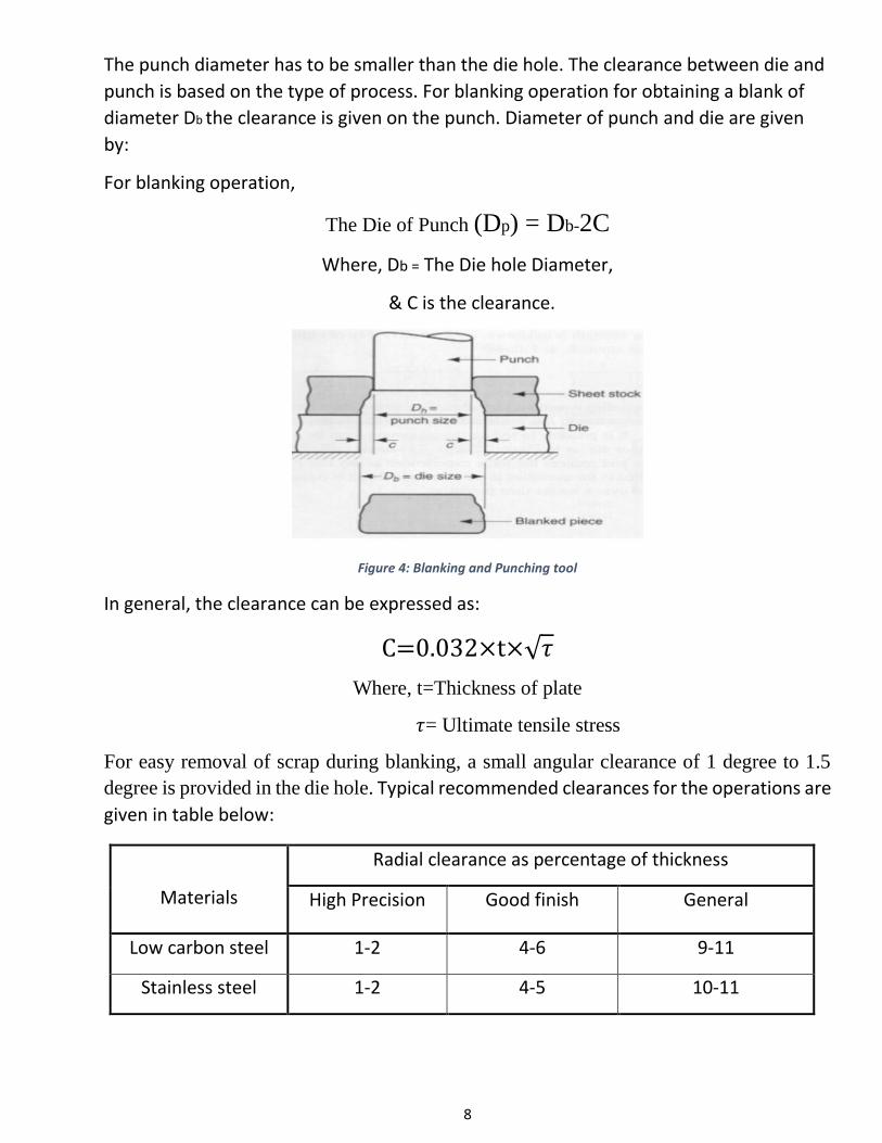
The punch diameter has to be smaller than the die hole. The clearance between die and
punch is based on the type of process. For blanking operation for obtaining a blank of
diameter Db the clearance is given on the punch. Diameter of punch and die are given
by:
For blanking operation,
The Die of Punch (Dp) = Db-2C
Where, Db = The Die hole Diameter,
& C is the clearance.
Figure 4: Blanking and Punching tool
In general, the clearance can be expressed as:
C=0.032×t×√𝜏
Where, t=Thickness of plate
𝜏= Ultimate tensile stress
For easy removal of scrap during blanking, a small angular clearance of 1 degree to 1.5
degree is provided in the die hole. Typical recommended clearances for the operations are
given in table below:
Materials
Radial clearance as percentage of thickness
High Precision Good finish General
Low carbon steel 1-2 4-6 9-11
Stainless steel 1-2 4-5 10-11
9
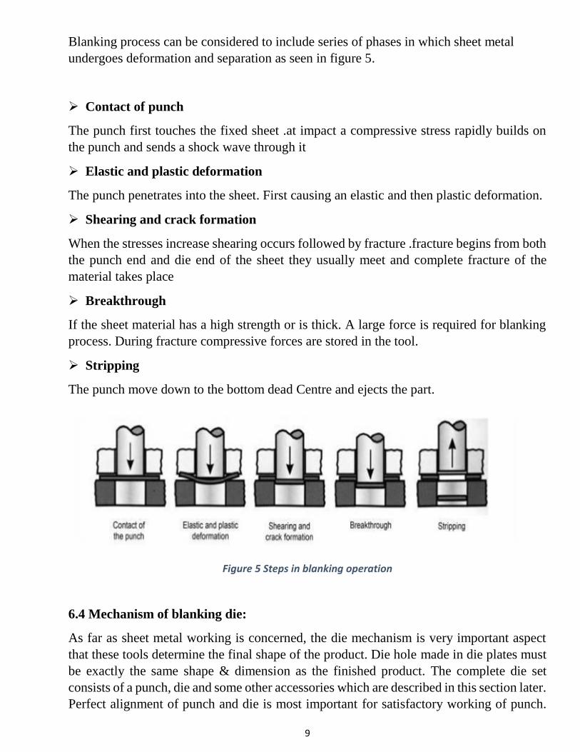
Blanking process can be considered to include series of phases in which sheet metal
undergoes deformation and separation as seen in figure 5.
Contact of punch
The punch first touches the fixed sheet .at impact a compressive stress rapidly builds on
the punch and sends a shock wave through it
Elastic and plastic deformation
The punch penetrates into the sheet. First causing an elastic and then plastic deformation.
Shearing and crack formation
When the stresses increase shearing occurs followed by fracture .fracture begins from both
the punch end and die end of the sheet they usually meet and complete fracture of the
material takes place
Breakthrough
If the sheet material has a high strength or is thick. A large force is required for blanking
process. During fracture compressive forces are stored in the tool.
Stripping
The punch move down to the bottom dead Centre and ejects the part.
Figure 5 Steps in blanking operation
6.4 Mechanism of blanking die:
As far as sheet metal working is concerned, the die mechanism is very important aspect
that these tools determine the final shape of the product. Die hole made in die plates must
be exactly the same shape & dimension as the finished product. The complete die set
consists of a punch, die and some other accessories which are described in this section later.
Perfect alignment of punch and die is most important for satisfactory working of punch.
10
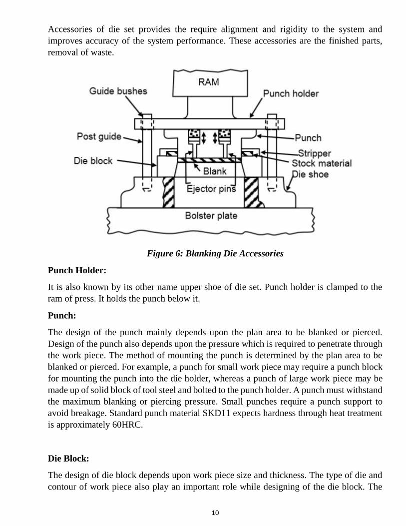
Accessories of die set provides the require alignment and rigidity to the system and
improves accuracy of the system performance. These accessories are the finished parts,
removal of waste.
Figure 6: Blanking Die Accessories
Punch Holder:
It is also known by its other name upper shoe of die set. Punch holder is clamped to the
ram of press. It holds the punch below it.
Punch:
The design of the punch mainly depends upon the plan area to be blanked or pierced.
Design of the punch also depends upon the pressure which is required to penetrate through
the work piece. The method of mounting the punch is determined by the plan area to be
blanked or pierced. For example, a punch for small work piece may require a punch block
for mounting the punch into the die holder, whereas a punch of large work piece may be
made up of solid block of tool steel and bolted to the punch holder. A punch must withstand
the maximum blanking or piercing pressure. Small punches require a punch support to
avoid breakage. Standard punch material SKD11 expects hardness through heat treatment
is approximately 60HRC.
Die Block:
The design of die block depends upon work piece size and thickness. The type of die and
contour of work piece also play an important role while designing of the die block. The
11
selection of size of the die block also depends upon the experience. Sectional components
may be screwed and doweled to a die holder with sections butting against each other. This
arrangement reduces the cutting forces.
Die Holder:
It is also called die shoe. Its work as a support for the die block and it is rigidly fastened to
the balster plate of the press.
Punch plate:
Punch plate is also known as punch retainer. This is fixed to the punch holder. Punch plate
serves as a guide way to hold the punch in right position and properly aligned. This makes
the replacement of punch quick and correct.
Backing plate:
Backing plate is used to distribute pressure uniformly over the whole area (maintains
uniform stress), it prevents the stress concentration on any portion of punch holder. This is
generally made of hardened steel inserted between the punch and punch holder.
Pilots:
Pilot is used for correct location of blank when it is fed by mechanical means. The pilot
enters into the previously pierced hole and moves the blank to the correct position to be
finally spaced by the stops. Normally pilots are fitted to the punch holders.
Guide Posts:
Accurate alignment between die opening and punch movement is very important. Guide
posts are used for correct alignment of punch and die shoe.
Strippers:
The main purpose of stripper is to remove the stock from the punch after blanking or
piercing operation. Stripper acting as a pressure pad and withstanding against the work
piece. The stock does not make contact with the stripper. Best method for guiding the strip
is the use of guide rails.
Stock stops and Automatic stops:
The device by which the strip has to be advanced correct distance after each blanking is
called stock stops. After each stroke of the press, an edge of previously blanked hole is
pushed against a dowel pin. To release the strip from the pin, enough clearance is provided
in a strip channel to allow the stock to be lifted above the pin during upward stroke of the
press. Skilled operator is required for such type of operation.
12
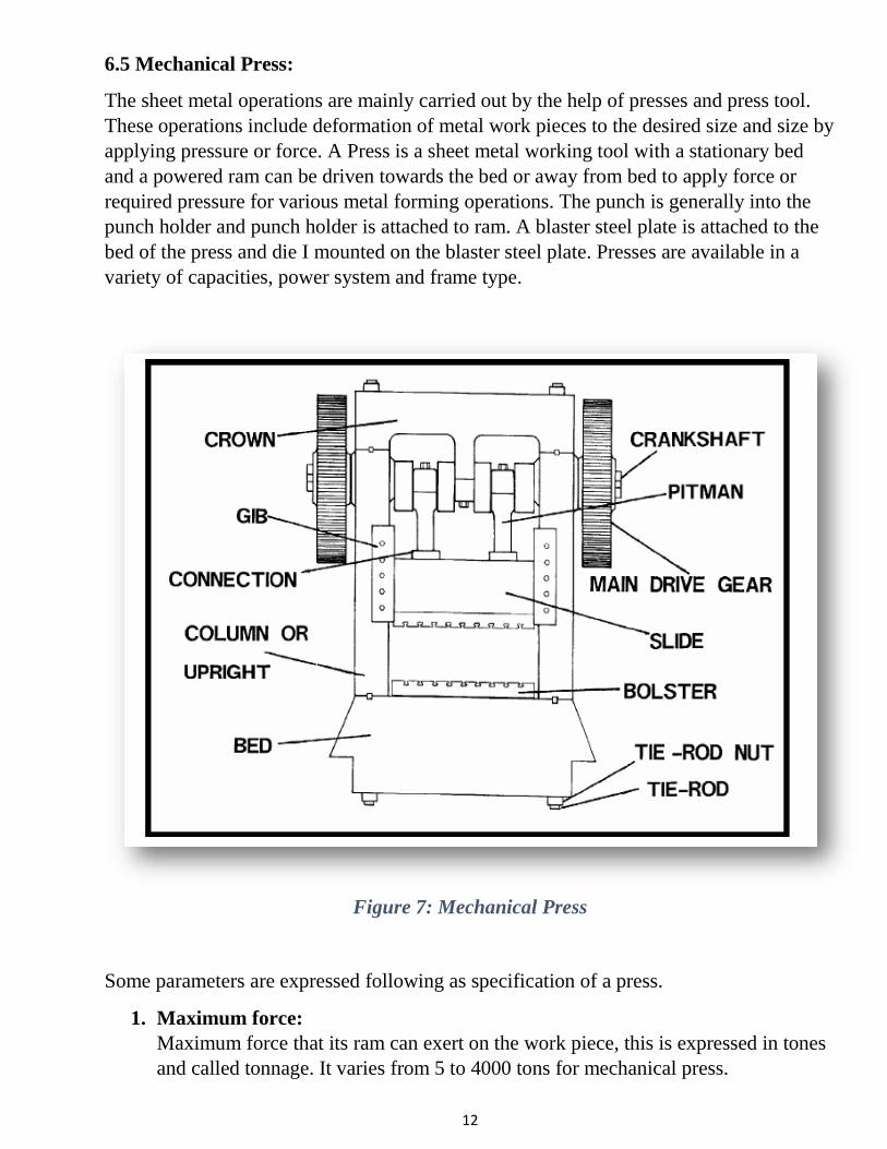
6.5 Mechanical Press:
The sheet metal operations are mainly carried out by the help of presses and press tool.
These operations include deformation of metal work pieces to the desired size and size by
applying pressure or force. A Press is a sheet metal working tool with a stationary bed
and a powered ram can be driven towards the bed or away from bed to apply force or
required pressure for various metal forming operations. The punch is generally into the
punch holder and punch holder is attached to ram. A blaster steel plate is attached to the
bed of the press and die I mounted on the blaster steel plate. Presses are available in a
variety of capacities, power system and frame type.
Figure 7: Mechanical Press
Some parameters are expressed following as specification of a press.
1. Maximum force:
Maximum force that its ram can exert on the work piece, this is expressed in tones
and called tonnage. It varies from 5 to 4000 tons for mechanical press.
13
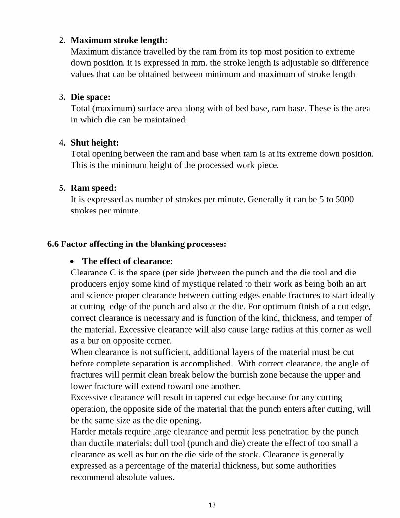
2. Maximum stroke length:
Maximum distance travelled by the ram from its top most position to extreme
down position. it is expressed in mm. the stroke length is adjustable so difference
values that can be obtained between minimum and maximum of stroke length
3. Die space:
Total (maximum) surface area along with of bed base, ram base. These is the area
in which die can be maintained.
4. Shut height:
Total opening between the ram and base when ram is at its extreme down position.
This is the minimum height of the processed work piece.
5. Ram speed:
It is expressed as number of strokes per minute. Generally it can be 5 to 5000
strokes per minute.
6.6 Factor affecting in the blanking processes:
The effect of clearance:
Clearance C is the space (per side )between the punch and the die tool and die
producers enjoy some kind of mystique related to their work as being both an art
and science proper clearance between cutting edges enable fractures to start ideally
at cutting edge of the punch and also at the die. For optimum finish of a cut edge,
correct clearance is necessary and is function of the kind, thickness, and temper of
the material. Excessive clearance will also cause large radius at this corner as well
as a bur on opposite corner.
When clearance is not sufficient, additional layers of the material must be cut
before complete separation is accomplished. With correct clearance, the angle of
fractures will permit clean break below the burnish zone because the upper and
lower fracture will extend toward one another.
Excessive clearance will result in tapered cut edge because for any cutting
operation, the opposite side of the material that the punch enters after cutting, will
be the same size as the die opening.
Harder metals require large clearance and permit less penetration by the punch
than ductile materials; dull tool (punch and die) create the effect of too small a
clearance as well as bur on the die side of the stock. Clearance is generally
expressed as a percentage of the material thickness, but some authorities
recommend absolute values.
14
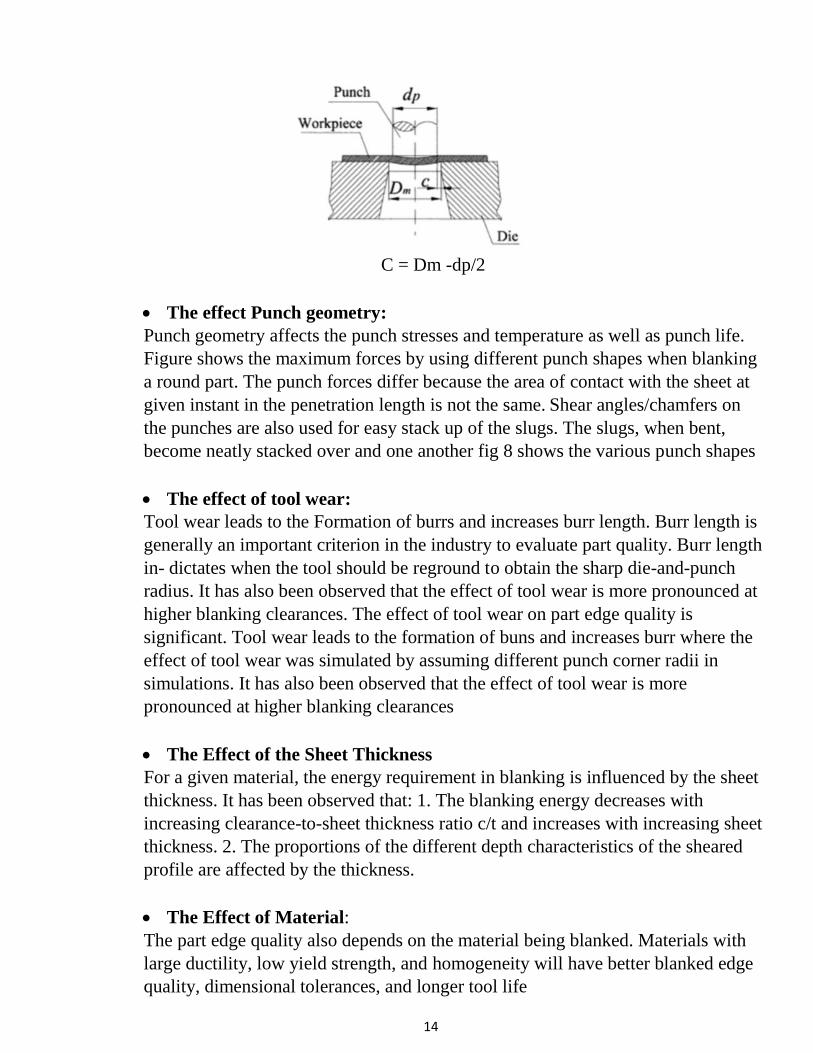
C = Dm -dp/2
The effect Punch geometry:
Punch geometry affects the punch stresses and temperature as well as punch life.
Figure shows the maximum forces by using different punch shapes when blanking
a round part. The punch forces differ because the area of contact with the sheet at
given instant in the penetration length is not the same. Shear angles/chamfers on
the punches are also used for easy stack up of the slugs. The slugs, when bent,
become neatly stacked over and one another fig 8 shows the various punch shapes
The effect of tool wear:
Tool wear leads to the Formation of burrs and increases burr length. Burr length is
generally an important criterion in the industry to evaluate part quality. Burr length
in- dictates when the tool should be reground to obtain the sharp die-and-punch
radius. It has also been observed that the effect of tool wear is more pronounced at
higher blanking clearances. The effect of tool wear on part edge quality is
significant. Tool wear leads to the formation of buns and increases burr where the
effect of tool wear was simulated by assuming different punch corner radii in
simulations. It has also been observed that the effect of tool wear is more
pronounced at higher blanking clearances
The Effect of the Sheet Thickness
For a given material, the energy requirement in blanking is influenced by the sheet
thickness. It has been observed that: 1. The blanking energy decreases with
increasing clearance-to-sheet thickness ratio c/t and increases with increasing sheet
thickness. 2. The proportions of the different depth characteristics of the sheared
profile are affected by the thickness.
The Effect of Material:
The part edge quality also depends on the material being blanked. Materials with
large ductility, low yield strength, and homogeneity will have better blanked edge
quality, dimensional tolerances, and longer tool life
15
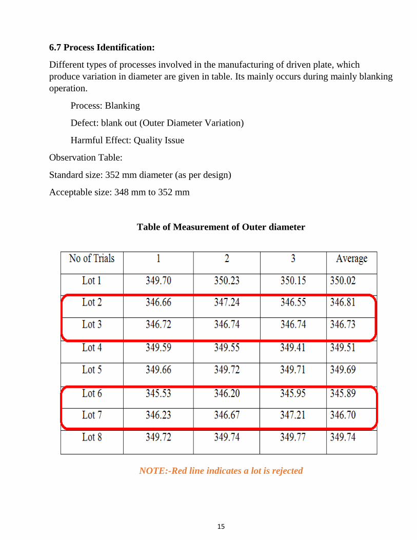
6.7 Process Identification:
Different types of processes involved in the manufacturing of driven plate, which
produce variation in diameter are given in table. Its mainly occurs during mainly blanking
operation.
Process: Blanking
Defect: blank out (Outer Diameter Variation)
Harmful Effect: Quality Issue
Observation Table:
Standard size: 352 mm diameter (as per design)
Acceptable size: 348 mm to 352 mm
Table of Measurement of Outer diameter
NOTE:-Red line indicates a lot is rejected
16
7. SOLUTION TO OVERCOME AFECTING FACTORS
7.1 Defect Understanding:
Following data was observed in industry with the help of design data book of driven plate
which shows the how important is to control the variation in diameter, a defect, which has
a major difficulty in assembly of clutch.
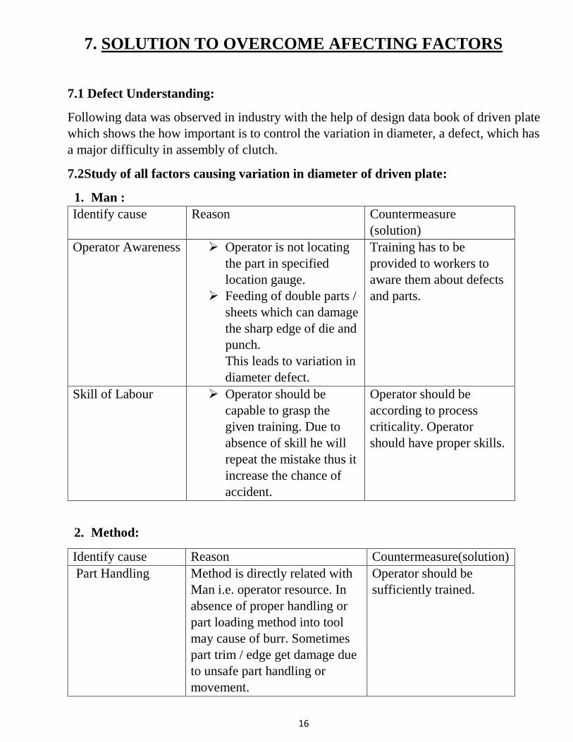
7.2Study of all factors causing variation in diameter of driven plate:
1. Man :
Identify cause Reason Countermeasure
(solution)
Operator Awareness Operator is not locating
the part in specified
location gauge.
Feeding of double parts /
sheets which can damage
the sharp edge of die and
punch.
This leads to variation in
diameter defect.
Training has to be
provided to workers to
aware them about defects
and parts.
Skill of Labour Operator should be
capable to grasp the
given training. Due to
absence of skill he will
repeat the mistake thus it
increase the chance of
accident.
Operator should be
according to process
criticality. Operator
should have proper skills.
2. Method:
Identify cause Reason Countermeasure(solution)
Part Handling Method is directly related with
Man i.e. operator resource. In
absence of proper handling or
part loading method into tool
may cause of burr. Sometimes
part trim / edge get damage due
to unsafe part handling or
movement.
Operator should be
sufficiently trained.
17
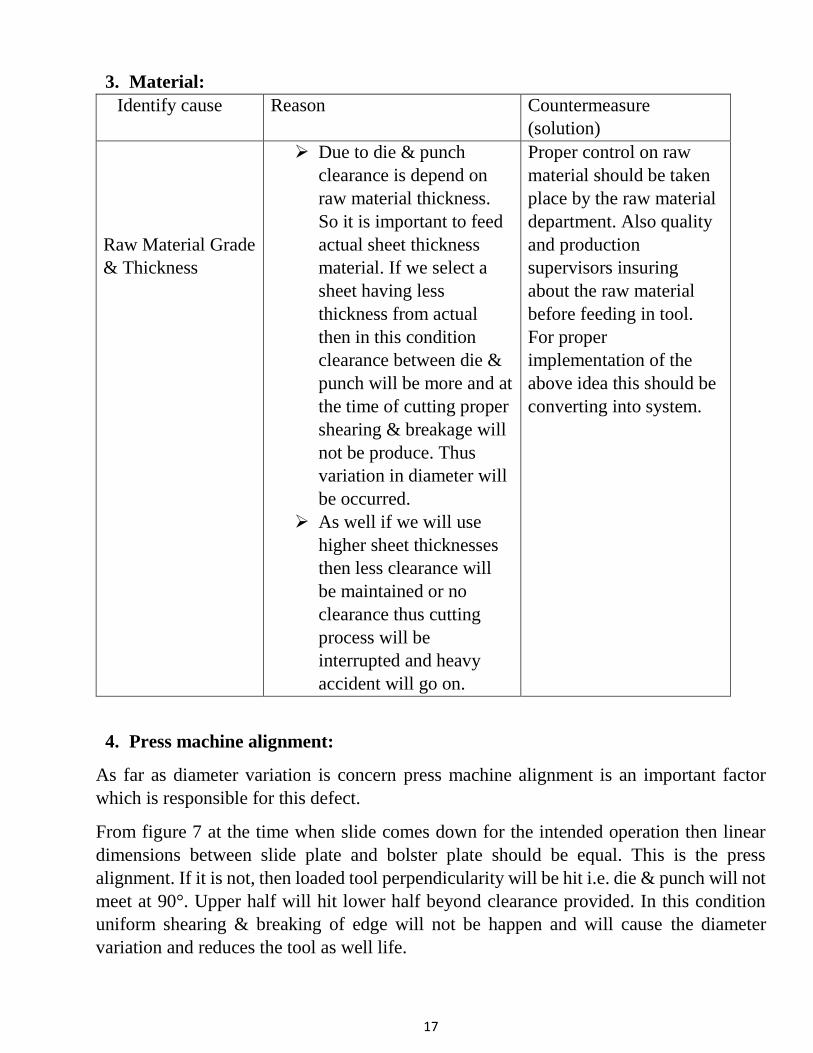
3. Material:
Identify cause Reason Countermeasure
(solution)
Raw Material Grade
& Thickness
Due to die & punch
clearance is depend on
raw material thickness.
So it is important to feed
actual sheet thickness
material. If we select a
sheet having less
thickness from actual
then in this condition
clearance between die &
punch will be more and at
the time of cutting proper
shearing & breakage will
not be produce. Thus
variation in diameter will
be occurred.
As well if we will use
higher sheet thicknesses
then less clearance will
be maintained or no
clearance thus cutting
process will be
interrupted and heavy
accident will go on.
Proper control on raw
material should be taken
place by the raw material
department. Also quality
and production
supervisors insuring
about the raw material
before feeding in tool.
For proper
implementation of the
above idea this should be
converting into system.
4. Press machine alignment:
As far as diameter variation is concern press machine alignment is an important factor
which is responsible for this defect.
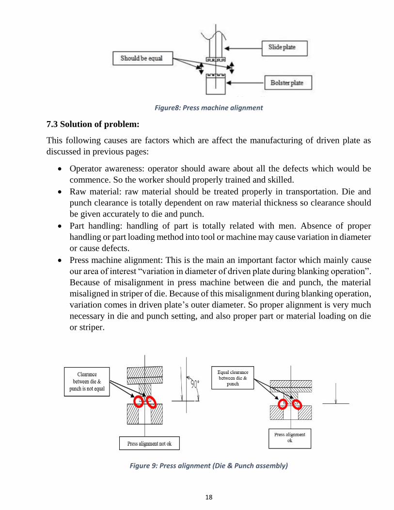
From figure 7 at the time when slide comes down for the intended operation then linear
dimensions between slide plate and bolster plate should be equal. This is the press
alignment. If it is not, then loaded tool perpendicularity will be hit i.e. die & punch will not
meet at 90°. Upper half will hit lower half beyond clearance provided. In this condition
uniform shearing & breaking of edge will not be happen and will cause the diameter
variation and reduces the tool as well life.
18
Figure8: Press machine alignment
7.3 Solution of problem:
This following causes are factors which are affect the manufacturing of driven plate as
discussed in previous pages:
Operator awareness: operator should aware about all the defects which would be
commence. So the worker should properly trained and skilled.
Raw material: raw material should be treated properly in transportation. Die and
punch clearance is totally dependent on raw material thickness so clearance should
be given accurately to die and punch.
Part handling: handling of part is totally related with men. Absence of proper
handling or part loading method into tool or machine may cause variation in diameter
or cause defects.
Press machine alignment: This is the main an important factor which mainly cause
our area of interest “variation in diameter of driven plate during blanking operation”.
Because of misalignment in press machine between die and punch, the material
misaligned in striper of die. Because of this misalignment during blanking operation,
variation comes in driven plate’s outer diameter. So proper alignment is very much
necessary in die and punch setting, and also proper part or material loading on die
or striper.
Figure 9: Press alignment (Die & Punch assembly)
19
8. CONCLUSION
In conclusion, after carried out comprehensive literature, there are few observation and
expected outcomes that can be made:
Most of studies are preferring experiment investigation as their methodology.
Furthermore, die & punch clearance and material properties are the most influential
process/design parameters that may cause variation in diameter of driven plate
during blanking operation.
Raw material should be of proper grade and thickness, so worker can adopt all
necessary operations on the material.
Material should properly loaded on striper of die, which die should properly aligned
with punch of mechanical press. Die setter should skilled and aware about all factors
that affects the dimensions of driven plate.
Skilled worker employed for manufacturing.
20
9. REFERENCE
1. Manufacturing science by Amitabh Ghosh & Kumar Malik.
2. Manufacturing Technology by P.N. Rao.
3. Sheet metal operations - Cutting and related processes, NPTEL material.
4. Mechanical Press types and nomenclature, Mechanical Press Types and
Nomenclature © 1993-2005 C02.doc C02.PDF David Alkire Smith, 530
Hollywood Drive, Monroe, Michigan 48162-2943 Rev August 19, 2005.
5. Causes & Preventation of Defects (Burr) In Sheet Metal Component by Pawan
Kumar Rai, Dr. Aas Mohammad, Hasan Zakir Jafri / International Journal of
Engineering Research and Applications (IJERA) ISSN: 2248-9622
www.ijera.com Vol. 3, Issue 4, Jul-Aug 2013, pp. 511-515
6. Geometrical Defect in Precision Blanking/Punching: A Comprehensive Review on
Burr Formation by H.Y. Chan and A.B. Abdullah School of Mechanical
Engineering, University Sains Malaysia, Engineering Campus, 14300 Nibong Tebal,
Penang, Malaysia.
7. An Overview Of Factors Affecting In Blanking Processes by Amol Totre, Rahul
Nishad, Sagar Bodke, International Journal of Emerging Technology and Advanced
Engineering Website: www.ijetae.com (ISSN 2250-2459, ISO 9001:2008 Certified
Journal, Volume 3, Issue 3, March 2013).
8. Application of fine piercing process for roller chain link plate to increase breaking
load of roller chain By Patil R.A., Prof. Gaikwad B.D., and Swapnil Kulkarni.

21

22

23