fretting fatigue of uncoated ti-6a1i4v general electric ... · common fretting wear between sliding...
TRANSCRIPT
AD-753 412
INI
Wear Resistant Coatingsfor Titanium Alloysfretting fatigue of uncoated Ti-6A1I4V
General Electric Company
prepared for
Air Force Materials Laboratory
NOVEMBER 1971
Distributed By:
National Technical Information ServiceIU. S. DEPARTMENT OF COMMERCE
AFML-TR-71-212
WEAR RESISTANT COATINGS FOR IiANIUM ALLOYS:FRETTING FATIGUE OF UNCOATED Ti-6AI-4V
R.K. Betts"General Electric Company
Is• Technical Report AFML-TR-71-212
1971 November
Approved .for public release;distribution unlimited
Reprodujced by
NATIONAL TECHNICALINFORMATION SERVICE
Springfield VA 22151 1973U S Deporiment of Commerce jf7Air Force Materials LaboratoryAir Force Systems Conudand .
Wright-Patterson Air Force Base, Ohio 45433
S '%
AFML-TR-71-212
WEAR RESISTANT COATINGS FOR TITANIUM ALLOYS:FRETTING FATIGUE OF UNCOATED Ti-6AI-4V
R.K. Betts
Approved for public release;distribution unlimited
1,\
.4i
FOREWORD
This Final Report was prepared for the United States Air Force MaterialsLaboratory, Contract F33615-70-C-1537, "Development and Evaldation of Coatingsfor Alleviating the Effect of Fretting on the Fatigue Life of Titanium Alloys,"performed during the period 1970 July 1 through 1971 August 31. The report wassubmitted by the author on 1971 September 15.
The contract was performed by the Materials and Process Technology Labora-tories, Aircraft Engine Group, General Electric Company under Air Force MaterialsLaboratory Project 7312, 'Metal Surface Deterioration and Protection", Task No.731201, "Metal Surface Prot-ction". It was accomplished under the technicaldirection of Mr. J. Jay Crosby of the Metals Branch (LLP), Metals and CeramicsDivision, Air Force Materials Laboratory, Wright-Patterson Air Force Base, Ohio.
Dr. I.I. Bessen, Manager, Coatings Technology Suboperation, General Electric,was tý'e program manager; and, Mr. R.K. Betts was in charge of tne tecanical effort.This technical effort has been reviewed and is approved.
I. PerlmutterChief, Metals BranchMetals and Cera.mics Division
ii
ABSTRACT
Classic fretting fatigue p3rformed in an in-situ manner between surfacesof shot-peened, forged Ti-6A1-4V was found not to affect the run-out stresscapability compared to nonfretted specimens in tests at room temperature.However, at 4000 F, a slight decrease in the run-out stress was oboerved,and at 6500 F a decrease of 30o resulted from severe surface interactiois,
At overstress levels of 10,000 psi above the nonfretted run-out Stress,fretting reduced the cyclic life capability by two orders of magnitude atroom temperature, and 21 orders at the elevated temperatures.
At overstress conditions, a narrow threshold of inexorable fretting fa-tigue damage occurred between l10 and 5 X l04 cycles. Fluorescent penetrantinspection was capable of revealing cracks in specimens interrupted from fret-ting after the threshold had been exceeded, which specimens were subsequentlytested to ft.tigue failure with no additional fretting.
Contact pressure from 5,000 to 75,000 psi in these in-situ frettingfatigue tests produced fretting damage. Very low pressure of 500 psi reducedfrettizig fatigue propensity at room temperature.
Common fretting wear between sliding surfaces of shot-peened Ti-6A1-4Vwas found not to affect the subsequent high cycle and low cycle fatigue prop-erties of Ti below certaln contact pressures and sliding displacements. Wearat a contact pressure of J.0,000 psi with 0.5 mil and 2.5 mils displacement for1000 strokes did not reduce the high cycle fatigue strength, nor did wear at1,000 psi with as much as 10 mils displacement for 1000 strokes affect thestrength. But, damage incurred at 10,000 and 50,000 psi with 5 mils dis-placement for 1,000 strokes did affect the high cycle and low cycle fatigueproperties.
iii
TABLE OF CONTENTS
Section Page
I INTRODUCTION 1
II SUMMARY AND RESULTS 3
1. Task 1 - Strain Fretting Fatigue 32. Task 2 - Sliding Wear Fatigue 5
III CONCLUSIONS 11
1. Task 1 - Strain Fretting Fatigue 112. Task 2 - Sliding Wear Fatigue 11
IV TECHNICAL PROGRAM 13
1. Background 13
2. Discussion of Wear Phenomena 13a. General Wear Processes 13b. Friction and Wear 14c. Forms of Wear 14d. Results of Wear 15
3. Wear and Fatigue Test Methods 15
a. Requirements 15b. High Cycle, Strain-Fretting Fatigue 16
c. Sliding Wear and Fatigue 164. Contractual Work Statement 20
a. Abstract 20b. Detailed Description 20
(1) Task 1 - Strain-Fretting Fatigue 20(2) Task 2 - Sliding Wear/Fatigue 21(3) Task 2 - Amendment 22
V EXPERIMENTAL WORK AND RESULTS 23
1. Specimen Preparation 23
2. Task 1 - Strain-Fretting Fatigue Tests 23a. High Cycle Fatigue Apparatus Calibration 23b. High Cycle Fatigue Test Results - Room Temperature 29c. Interrupted Fretting Fatigue 39d. Elevated Temperature Tests 45
3. Task 2 - Sliding Wear/Fatigue 49a. High Cycle Fatigue Effects from Sliding Wear 49
(1) 10,000 PSI Contact Pressure, 5-Mil Stroke 56(2) 10,000 PSI Contact Pressure, 0.5 - 1-Mil Stroke 61(3) 1000 PSI Contact Pressure, 5-Mil Stroke 61
Preceding page blank
TABLE OF CONTENTS (Concluded)
Section Page
(4) 10,000 PSI C-atact Pressure, 2.5-Mil Stroke 66"(5) 1000 PSI Contact Pressure, 10-Mil Stroke 66
b. Low Cycle Fatigue Effects from Sliding Wear 66
VI REFERENCES 71
vi
LIST OF ILLUSTRATIONS
Figure Page
1. Effect of In-Situ Fretting During High Cycle Fatigue ofShot-Peened T1-6A1-4V at Room Temperature, 4000 F, and6500 F. 4
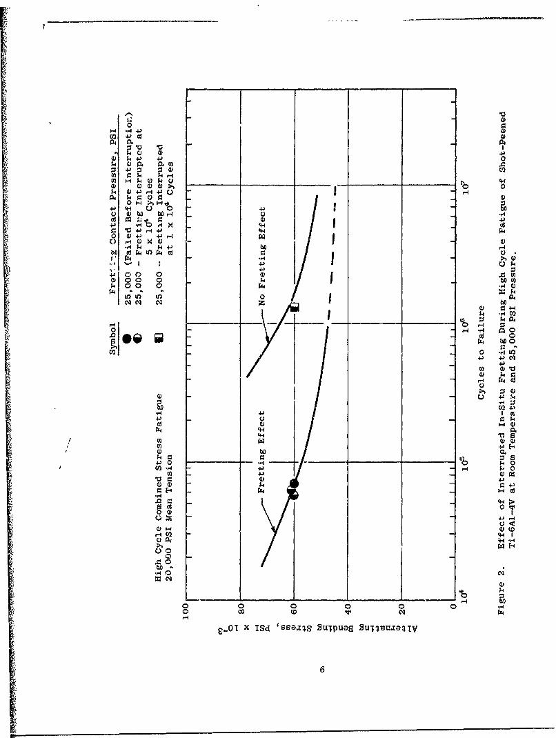
2. Effect of Interrupted In-Situ Fretting During High CycleFatigue of Shot-Peened Ti-6A1-4V at Room Temperature and25,000 PSI Pressure. 6
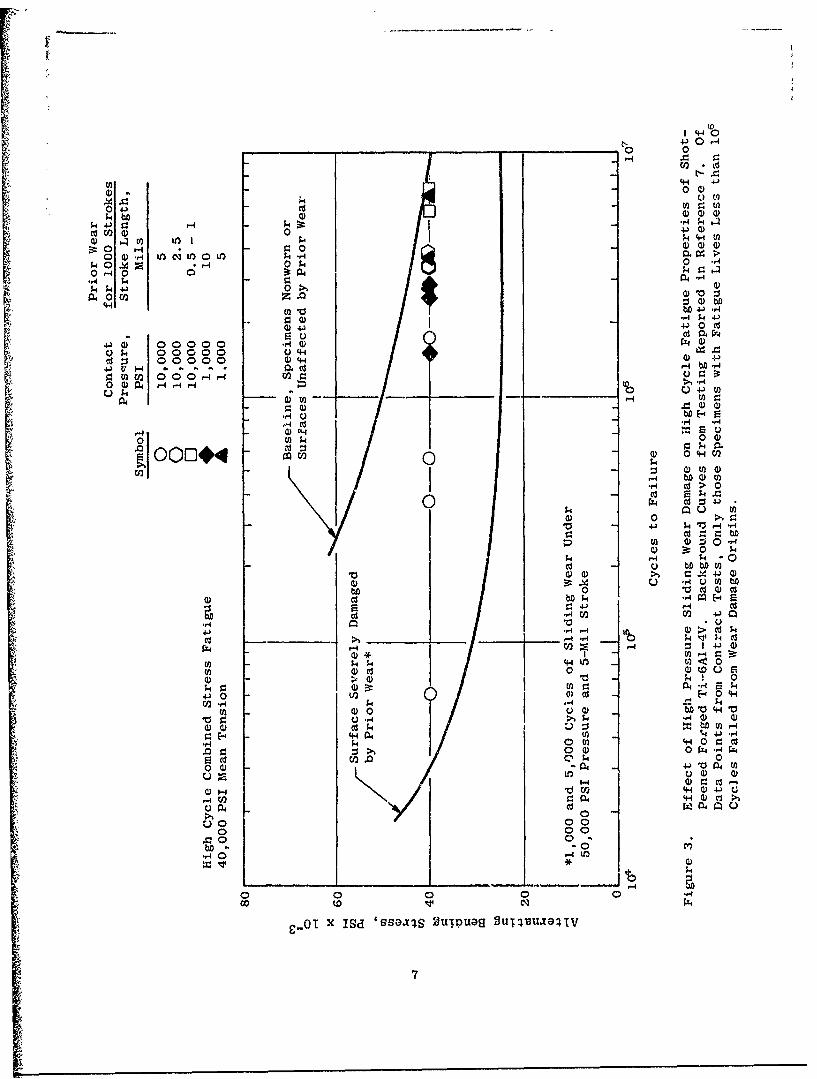
3. Effect of High Pressure Sliding Wear Damage on High CycleFatigue Properties of Shot-Peened, Forged Ti-6A1-4V.Background Curves from Testing Reported in Reference 7.Of Data Points from Contract Tests, Only those Specimenswith Fatigue Lives Less than 106 Cycles Failed from WearDamage Origins. 7
4. Summary of Wear Test Conditions for 1000 Strokes, Indicatingthe Effect on High Cycle Fatigue Properties of Shot-PeenedTi-6AI- 4V. 9
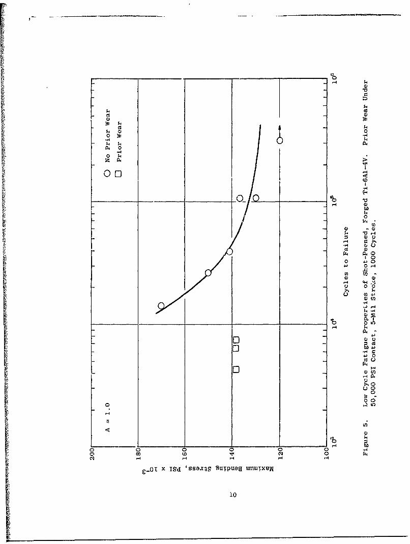
5. Low Cycle Fatigue Properties of Shot-Peened, Forged
Ti-6A1-4V. Prior Wear Under 50,000 PSI Contact, 5-MilStrcke, 1000 Cycles. 10
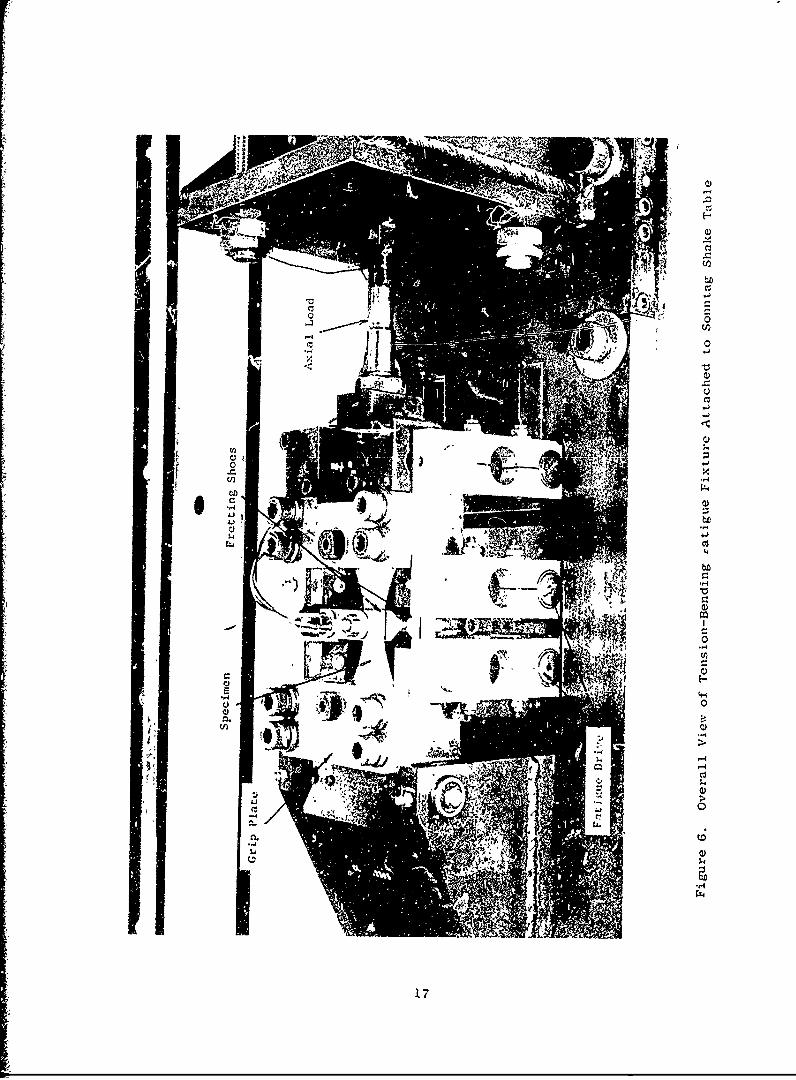
6. Overall View of Tension-Bending Fatigue Fixture Attached toSonntag Shake Table. 17
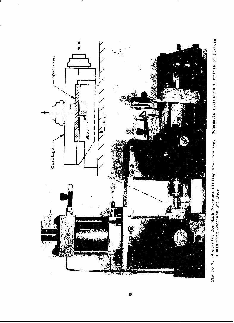
7. Apparatus for High Pressure Sliding Wear Testing. SchematicIllustrates Details of Fixture Containing Specimen and Shoe. 18
8. End View of Apparatus for High Pressure Sliding Wear Testing. 19
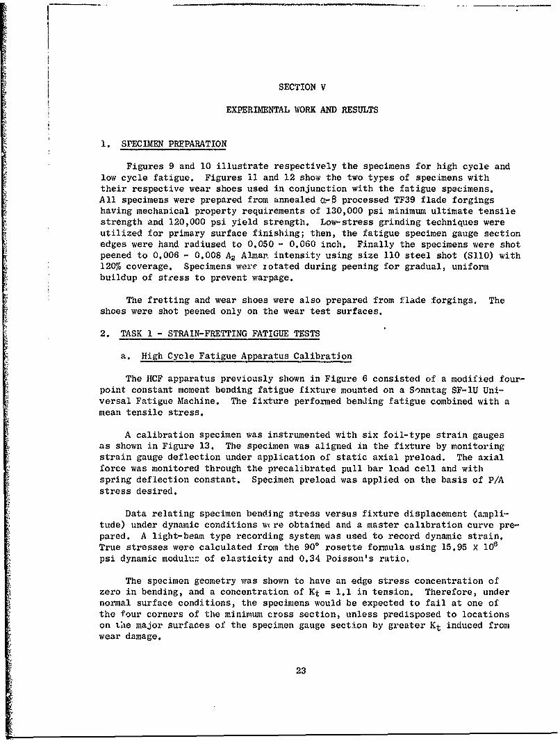
9. Configuration of High Cycle Fatigue Specimen. 24
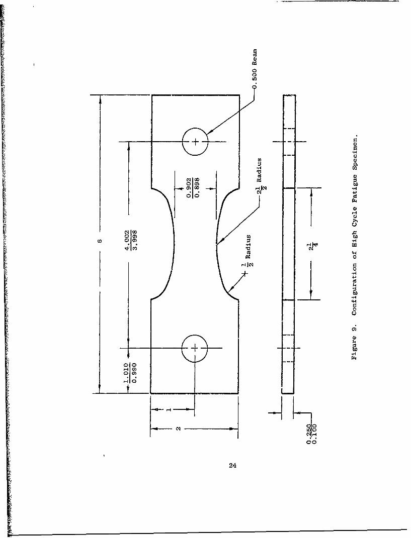
10. Configuration of Low Cycle Fatigue Specimen. 25
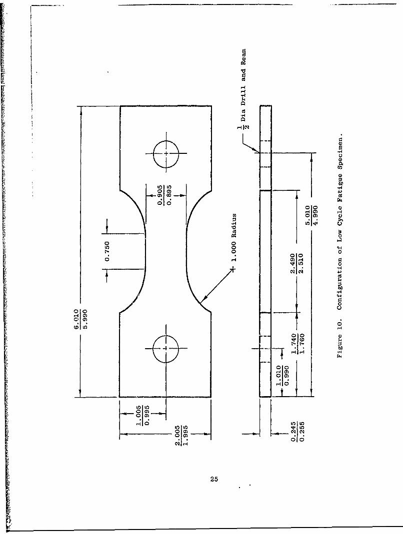
11. High Cycle Fretting Fatigue Specimen, Wear Shoes, and ClampingBolts. Specimen Shows Strain Gauge Instrumentation forBending Stress Measurement at Edges of Shoe Contact Area.Bolts Show Instrumentation Leads from Internal Strain Gauges. 26
12. Specimen and Shoe Combination for High Pressure Sliding WearTest. 27
13. Calibration Specimen Illustrating Placement of Strain Gaugeson Specimen Surfaces. 28
vii
LIST OF ILLUSTRATIONS (Continued)
Figure Page
14. View of the Fretting Fatigue Test Fixture Illustrating theMethod of Shoe Assembly ior Low Contact Pressure (500 PSI).The Springs Were Precalibrated to Provide Approximately 90Lbs of Contact Force. 30
15. Effect of In-Situ Fretting During High Cycle Fatigue ofShot-Peened Ti-6AI-4V at Room Temperature. 32
16. Fretting Fatigue Specimen 56 Tested Under 500 PSI ShoeContact Pressure at 20,000 PSI Mean Tension and 60,000 PSIAlternating Bending Stress to 6 X 10⁵ Cycles. The Shoe
Contact Area Shows Fretting Debris Along the Edges and Pitsat the Ends. The Failure Initiated from a Single Origin
Visible on the Fracture Face, Corresponding to FrettingDamage Along the Edge of the Shoe Contact Area. 33
17. Fretting Fatigue Specimen 48 Tested Under 5000 PSI ShoeContact Pressure at 20,000 PSI Mean Tension and 60,000 PSIAlternating Bending Stress to 9.4 X 10⁴ Cycles. Upper
Photograph Illustrates the Fretted Area where the Shoe Wasin Contact. Origins Visible in the Lower Photograph Showthe initiation of Failure from Surface Damage at the Edge of
the Shoe Contact Area (6W). 34
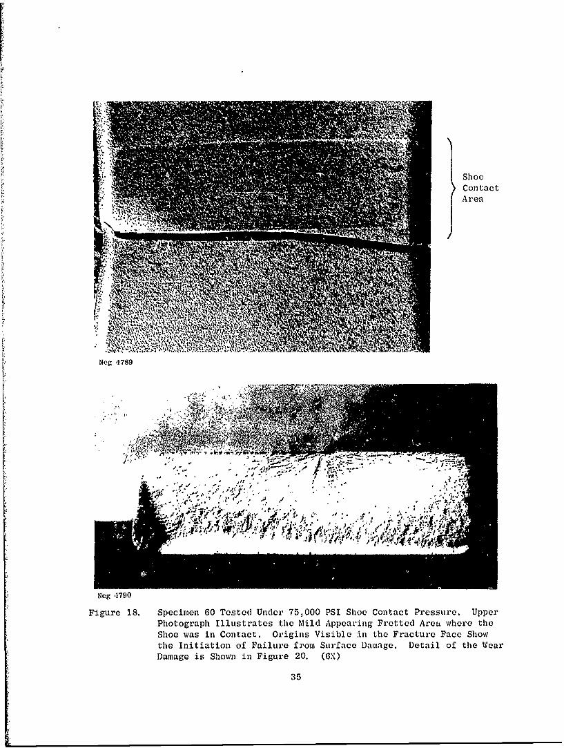
18. Specimen 60 Tested Under 75,000 PSI Shoe Contact Pressure.Upper Photograph Illustrates the Mild Appearing Fretted Areawhere the Shoe Was in Contact. Origins Visible in the FractureFace Show the Initiation of Failure from Surface Damage.Detail of the Wear Damage is Shown in Figure 20. 35
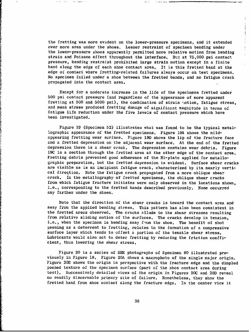
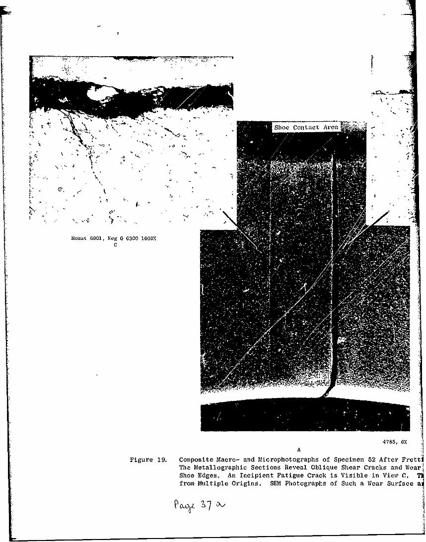
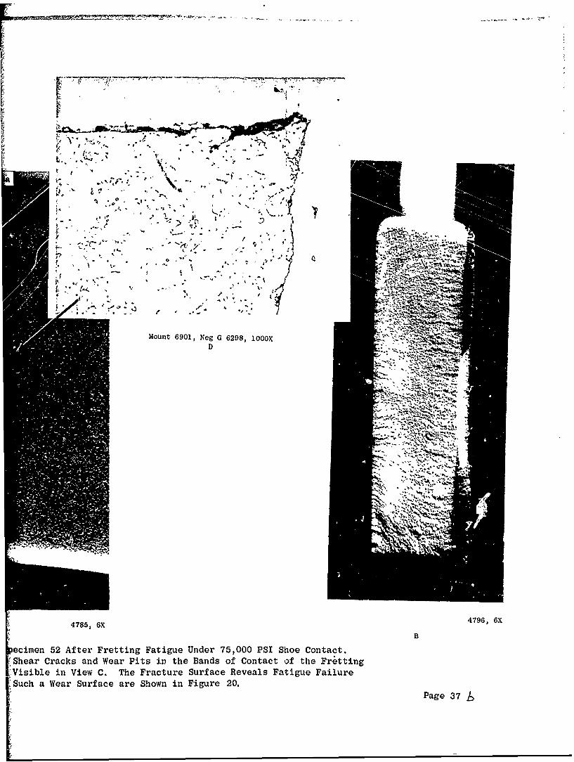
19. Composite Macro- and Microphotographs of Specimen 52 afterFretting Fatigue Under 75,000 PSI Shoe Contact. The Metallo-graphic Sections Reveal Oblique Shear Cracks and Wear Pits inthe Bands of Contact of the Fretting Shoe Edges. An IncipientFatigue Crack is Visible in View C. The Fracture Surface Re-veals Fatigue Failure from Multiple Origins. SKM Photographsof Such a Wear Surface are Shown in Figure 20. 37
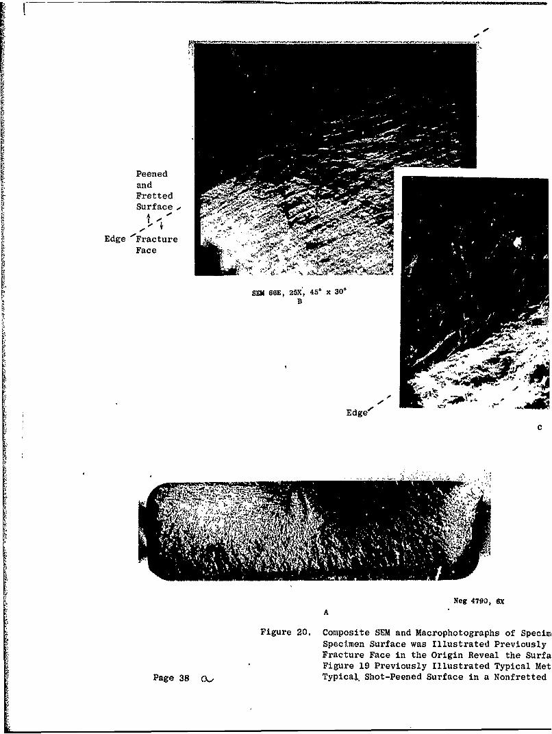
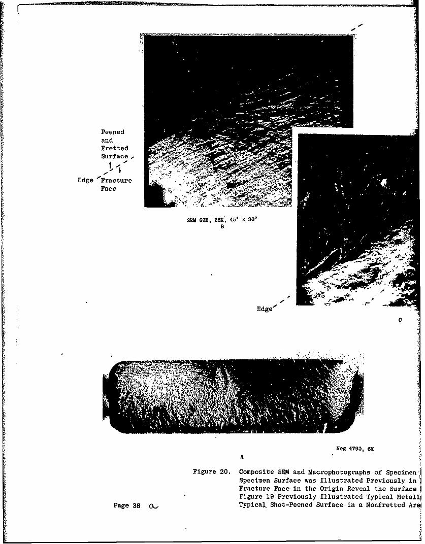
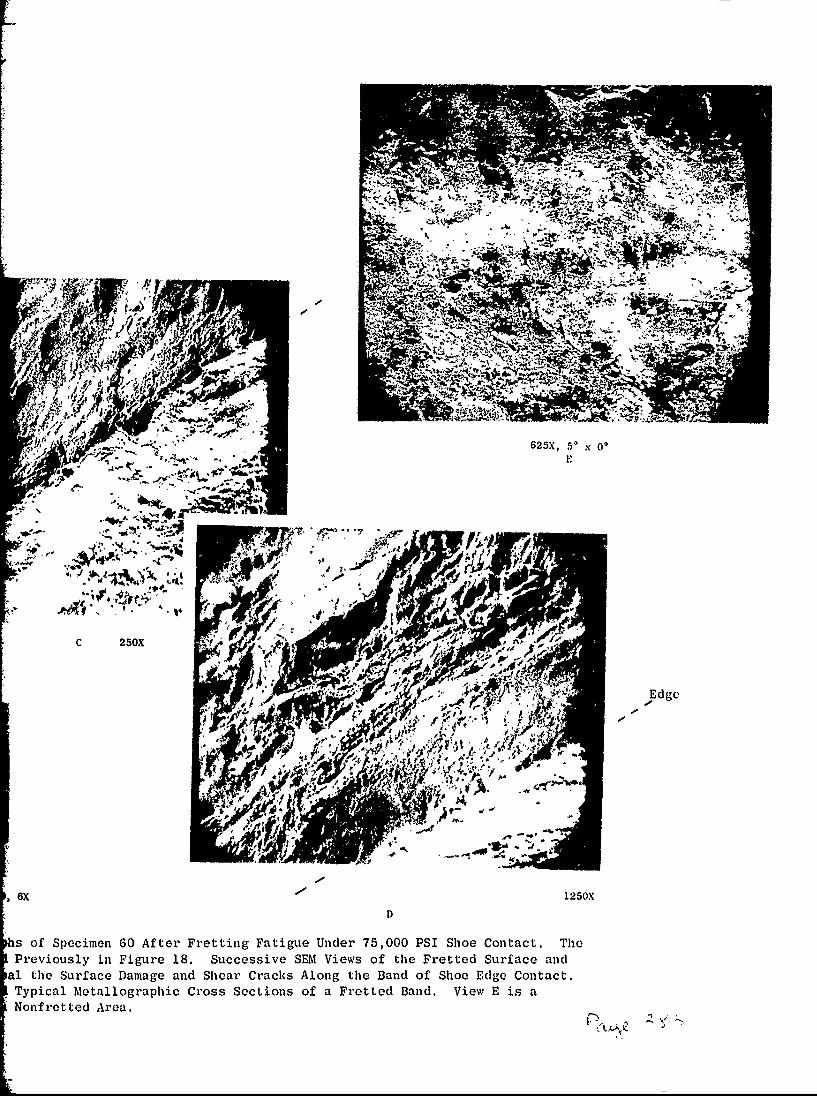
20. Composite SEM and Macrophotographs of Specimen 60 after Fret-ting Fatigue Under 75,000 PSI Shoe Contact. The SpecimenSurface Was illustrated Previously in Figure 18. SuccensiveSEM Views of the Fretted Surface and Fracture Face in theOrigin Reveal the Surface Damage and Shear Cracks Along theBand of Shoe Edge Contact. Figure 19 Previously IllustratedTypical hietallographic Cross Sections of a Fretted Band.View E Is a Typical Shot-Peened Surface in a Nonfretted Area. 38
viii
LIST OF ILLUSTRATIONS (Continued)
Figure Page
21. Autoradiograph Exposures of Kryptonized Fretted Specimens.The Pressure Bands were Effectively Outlined by the Method,but Crack Detection was Difficult. (industrial Nucleonics) 40
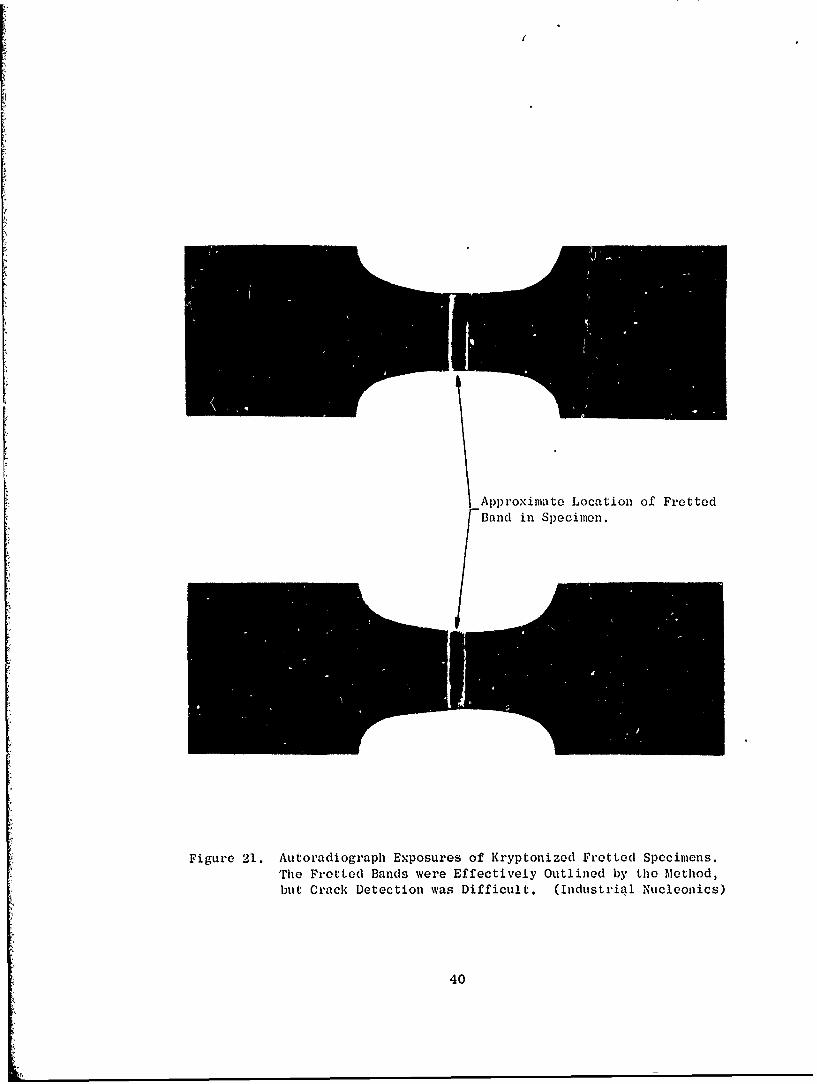
22. Fretting Fatigue Specimen 61 Photographed Under UltravioletLight, Revealing Fluorescent Penetrant in the Fretted Bandsof the Shoe Contact Areas. The Specimen Was Fretted Under25,000 PSI Shoe Contact Pressure at 20,000 PSI Mean Tensionand 60,000 PSI Alternating Bending Stress, InterruptedAfter 5 X 10⁴ Cycles for Inspection. The Right-Hand Bandin Each View Shows Bright Fluorescence Corresponding toCracks where the Specimen Eventually Failed (See Figure 23)(Neg 4771, 4772, 3.5X) 42
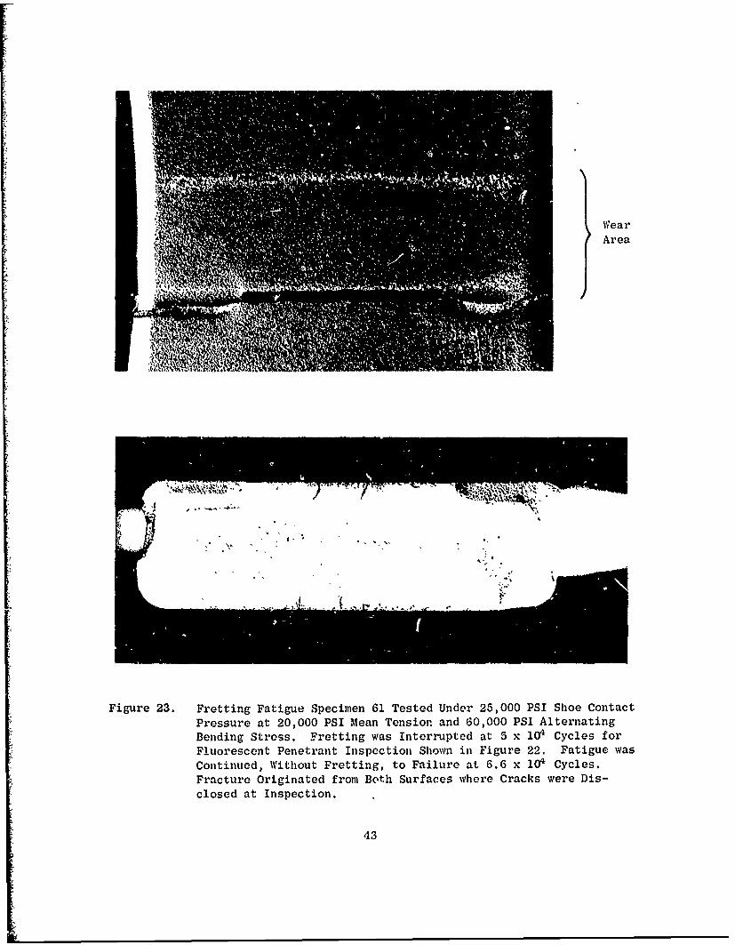
23. Fretting Fatigue Specimen 61 Tested Under 25,000 PSI ShoeContact Pressure at 20,000 PSI Mean Tension and 60,000 PSIAlternating Bending Stress. Fretting Was Interrupted at5 X 104 Cycles for Fluorescent Penetrant Inspection Shownin Figure 22. Fatigue Was Continued, without Fretting, toFailure at 6.6 X 10 Cycles. Fracture Originated from BothSurfaces where Cracks Were Disclosed at Inspection. 43
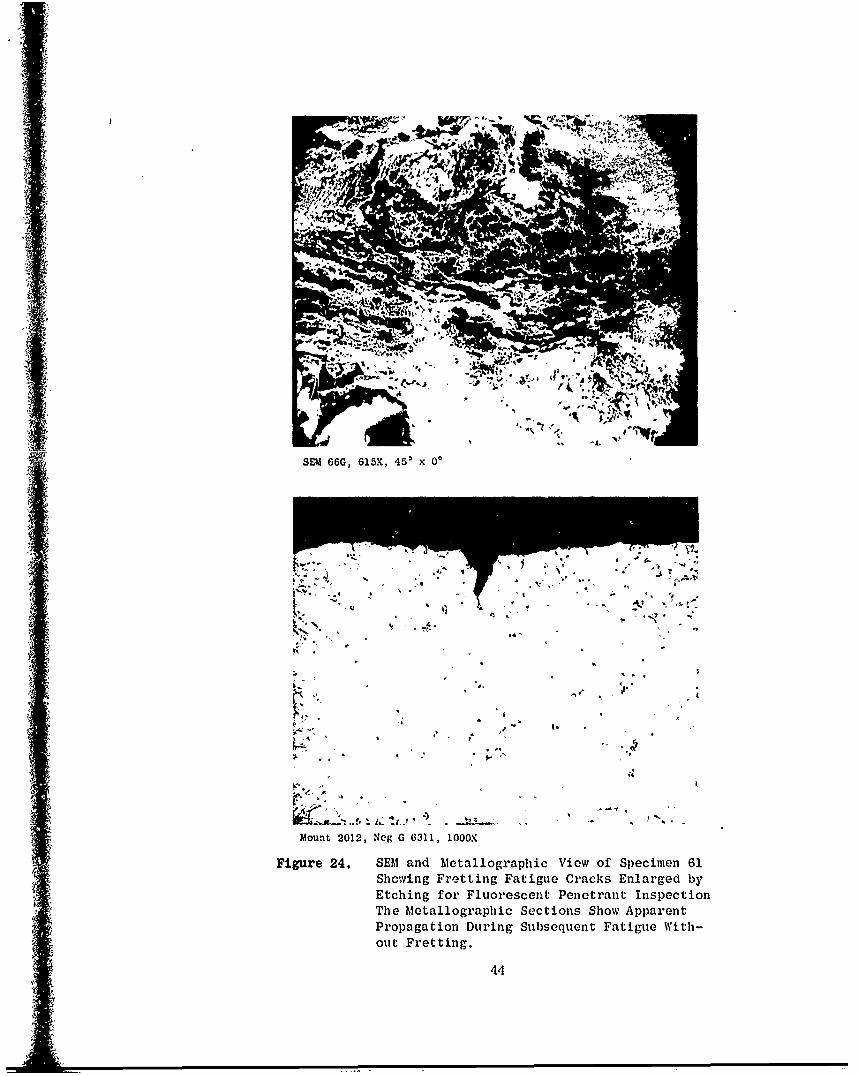
24. SEM and Metallographic Views of Specimen 61 Showing FrettingFatigue Cracks Enlarged by Etching for Fluorescent PenetrantInspection. The Metallographic Sections Show Apparent Pro-pagation During Subsequent Fatigue without Fretting. 44
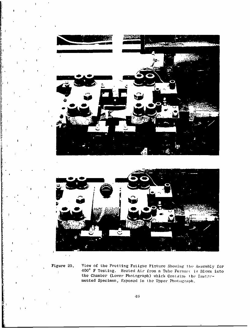
25. View of the Fretting Fatigue Fixture Showing the Assemblyfnr 4000 F Testing. Heated Air from a Tube Furnace is Blown
into the Chamber (Lower Photograph) which Contains the In-strumented Specimen, Exposed in the Upper Photograph. 46
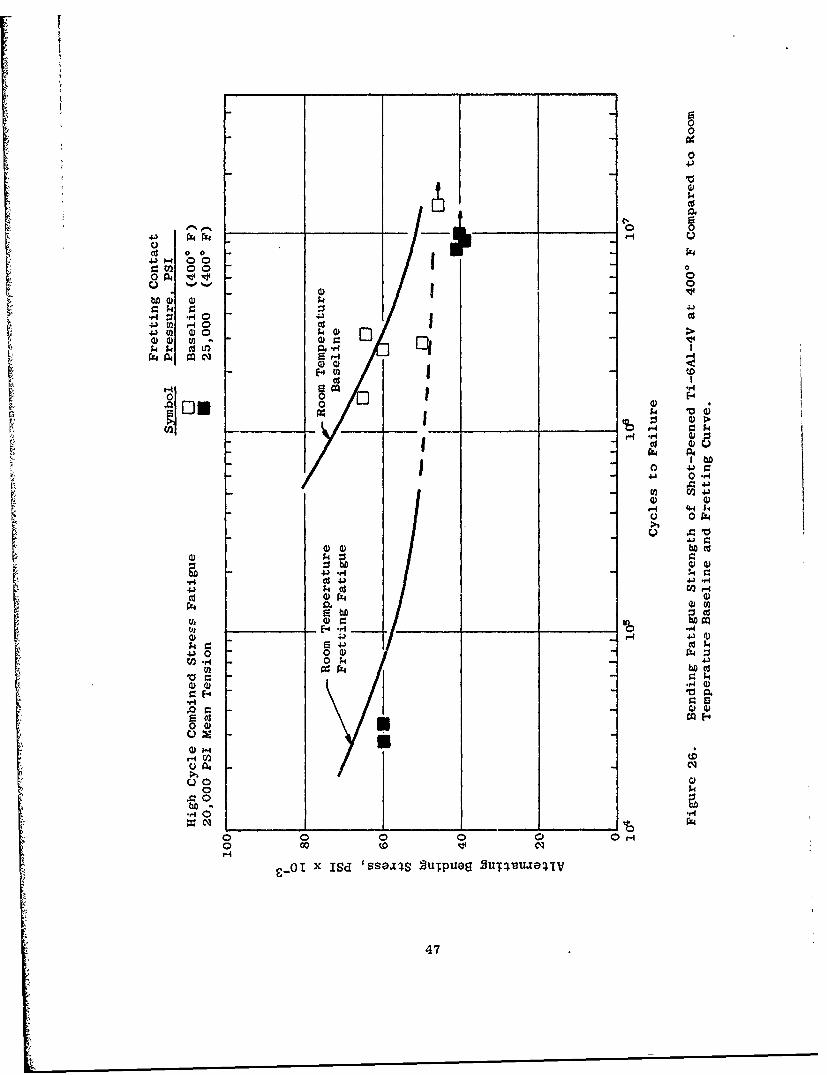
26. Bending Fatigue Strength of Shot-Peened Ti-6A1-4V at 400' FCompared to Room Temperature Baseline and Fretting FatigueCurves from Figure 1. Only the Specimens with Lives Lessthan 106 Cycles Failed Due to Fretting. 47
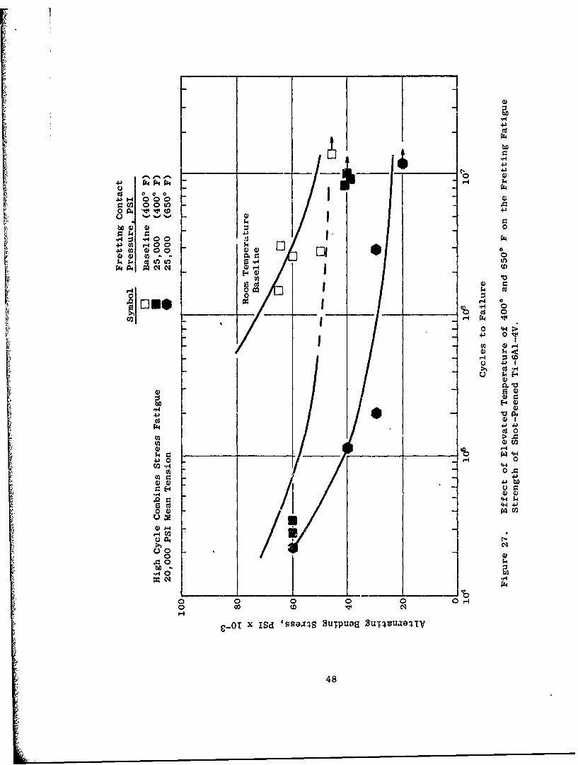
27. Effect of Elevated Temperatures of 4000 and 6500 F on theFretting Fatigue Strength of Shot-Peened Ti-6AI-4V. 48
ix
LIST OF ILLUSTRATIONS (Continued)
Figure Page
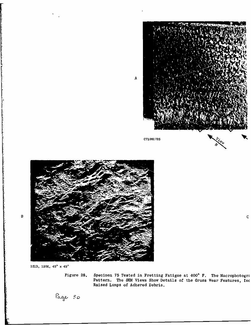
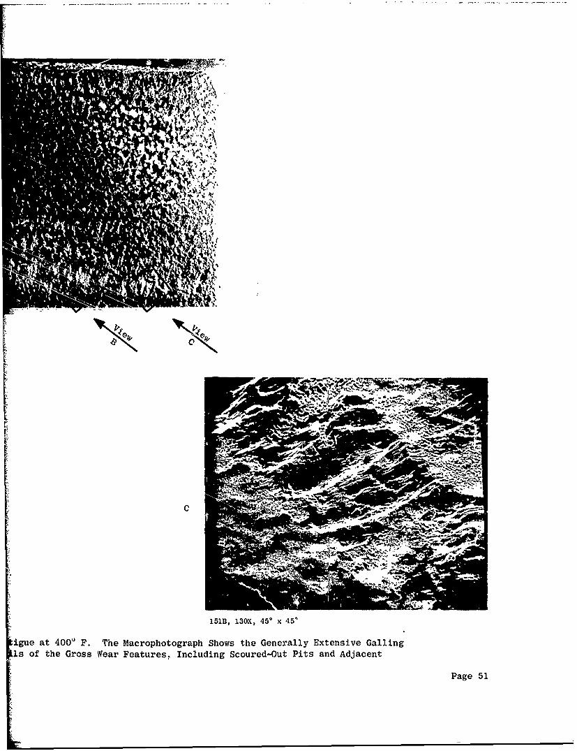
28. Specimen 75 Tested in Fretting Fatigue at 4000 F. TheMacrophotograph Shows the Generally Extensive GallingPattern. The SEM Views Show Details of the Gross WearFeatures, Including Scoured-Out Pits and Adjacent Raised
Lumps of Adhered Debris. 51
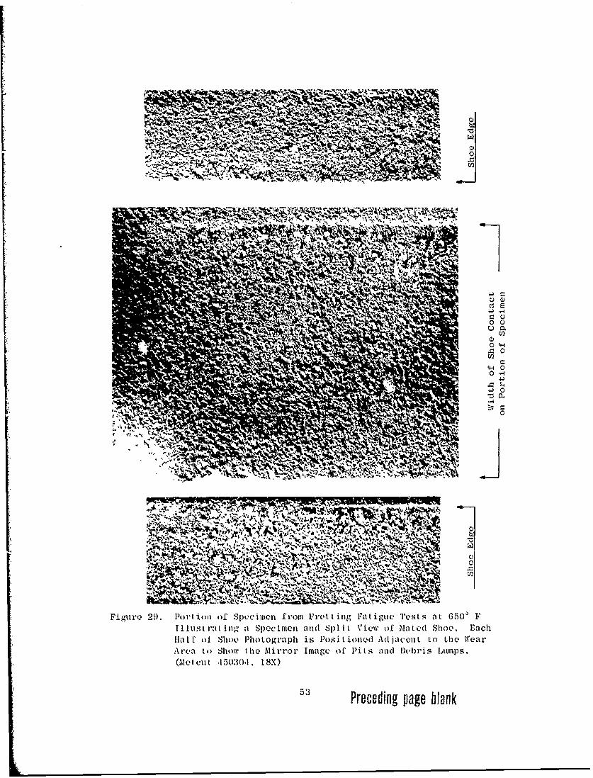
29. Portion of Specimen from Fretting Fatigue Tests at 650' F
Illustrating a Specimen and Split View of Mated Shoe. EachHalf of Shoe Photograph is Positioned Adjacent to the WearArea to Show the Mirror Image of Pits and Debris Lumps.
(Metcut 450304, 18X) 53
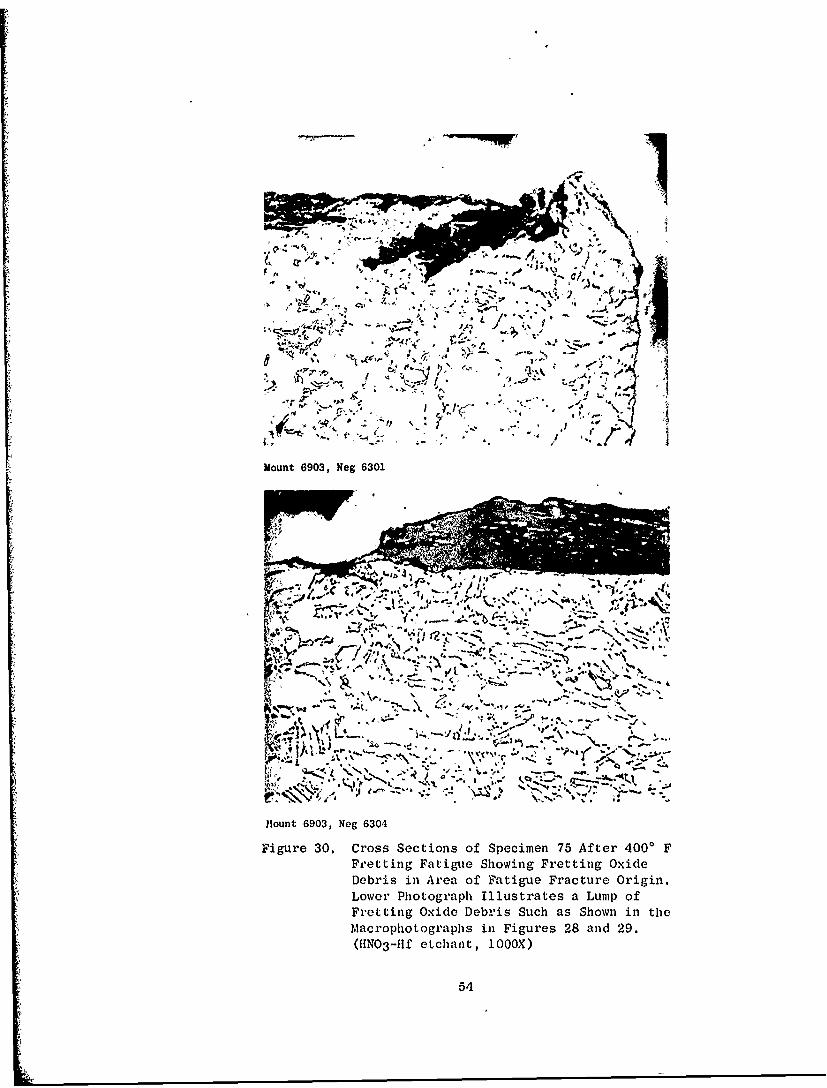
30. Cross Sections of Specimen 75 after 4000 F FreLting Fatigue
Showing Fretting Oxide Debris in Area of Fatigue FractureOrigin. Lower Photograph Illustrates a Lump of FrettingOxide Such as Shown in the Macrophotographs in Figures 28and 29. (HNO 3 -Hf Etchant, 1000X) 54
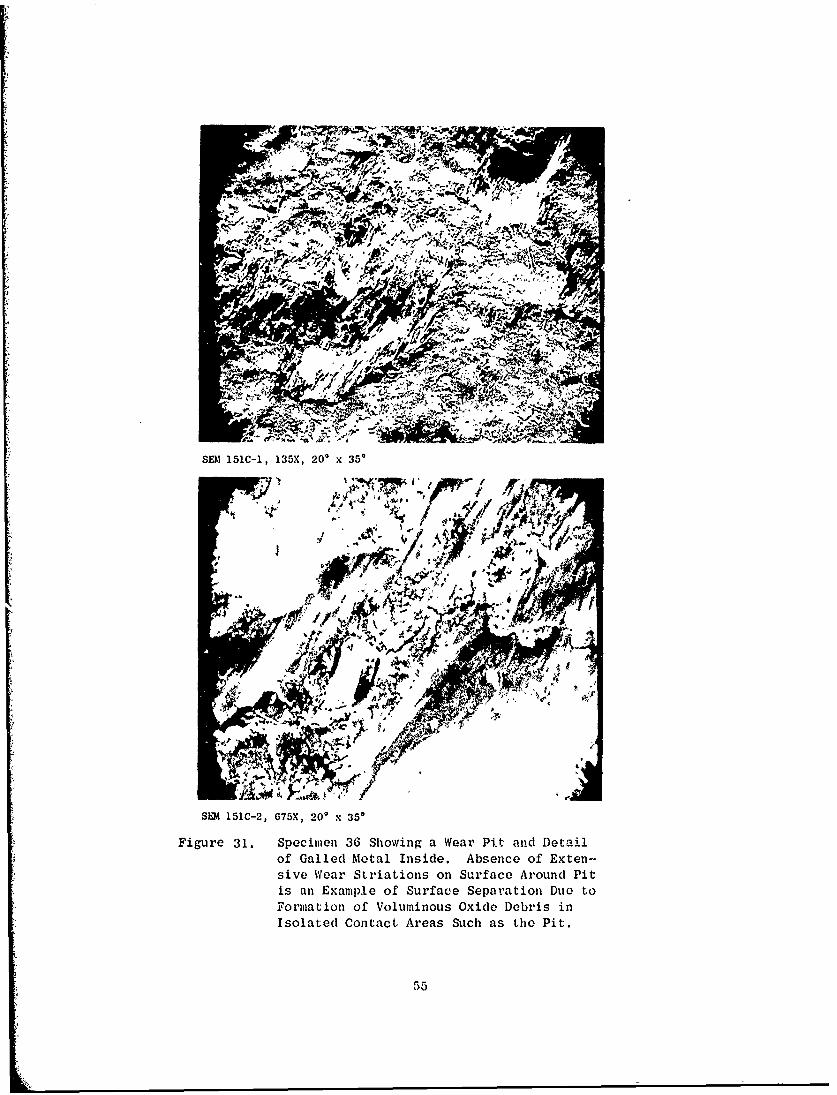
31. Specimen 36 Showing a Wear Pit and Detail of Galled MetalInside. Absence of Extensive Wear Striations on SurfaceAround Pit Is an Example of Surface Separation Due to Form-
ation of Voluminous Oxide Debris in Isolated Contact AreasSuch as the Pit. 55
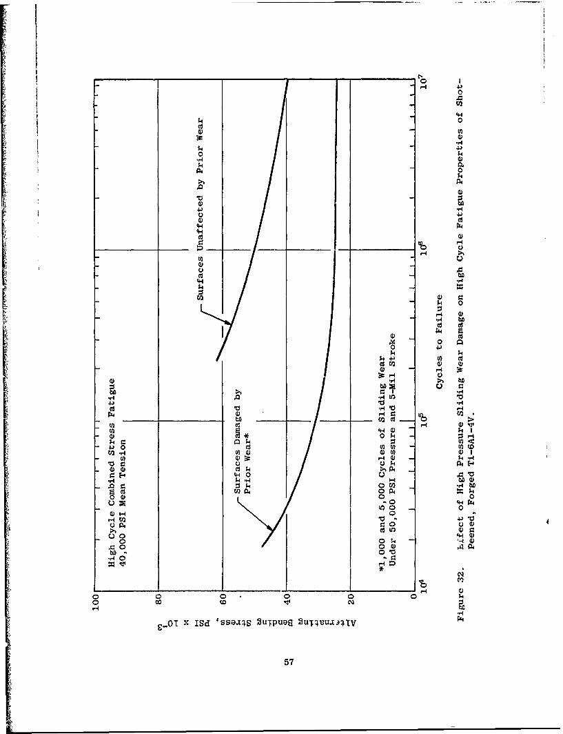
32. Effect of High Pressure Sliding Wear Damage on High CycleFatigue Properties of Shot-Peened, Forged Ti-6A1-4V. DataCuves from Background Tests Reported in Reference 7. 57
33. Specimen 38 Illustrating the Galling Wear and Fatigue FracturePattern after Testing under 10,000 PSI Contact Pressure with a5-Mil Stroke. (Metcut, 6X) 59
34. Specimen 39 Showing Detail of Galled Surface after Wear under10,000 PSI Contact Pressure with a 5-Mil Stroke. (C71081728,13X) 60
35. Specimen 38 Showing Wear Striations and Detail of DebrisLayer after Galling Wear under 10,000 PSI Contact Pressureand a 5-Mil Stroke. 62
36. Metallographic Section of Specimen 38 Showing Wear DebrisLayer in Substrate Pit. (Mount 1917, Neg G6305, 100OX) 63
x
LISn Or' ILLUSTIIA'TIONS (Conc luded)
Figure Page
37. Specimen 41 Illustrating Very Mild Wear Pattern onShoe and Specimen after Wear Test under 10,000 PSIContact Pressure and 0.5 - 1-Mil Stroke. (Metcut,6X) 64
38. Specimen 45 Illustrating Wear Pattern on Shoe and
Specimen after Testing under 1000 PSI Pressure anda 5-Mil Stroke. (Metcut, 6X) 65
39. Specimen 27 Showing Wear and Fracture Pattern afterLow Cycle Fatigue Wear Testing under 50,000 PSI
Contact Pressure and a 5-Mil Stroke. (Metcut, 6X) 67
40. Specimen 27 Showing Wear Debris of Shoe (Upper Photo-graph) and Galled Metal Flakes on Specimen (LowerPhotograph) after Testing under 50,000 PSI Contact
Pressure and a 5-Mil Stroke. 68
41. Specimen 27 Showing Metallographic Sction of WearShoe and ol SpLcim.en Fracture Edge in the Vicinityof a Failure Origin. (1000X) 69
xi
SECTION I
INTRODUCTION
Titanium and its alloys present one of the most critical challenges inmaterials engineering for modern gas turbine engines and aircraft structures.While it offers excellent strength-to-weight advantages and other favorableproperties, its fatigue life is extremely sensitive to surface conditions,particularly to damage from wear.
The purpose of the work performed under this Contract was to define andestablish conditions of fretting wear on uncoated, shot-peened Ti-6A1-4V underwhich conditions fatigue e4!fects may be expected in aircraft gas turbine enginecompressor applicazions. The r3sults were expected to identify conditions ofengine design under whizh the fatigue effects of wear may be avoided and toestablish appropriate test conditions for subsequent evaluation of fretting-preventive coatings. The test techniques used were based on studies of wearand protective materials conducted by and for the Material and Process Tech-nology Laboratories of the General Electric Company, Aircraft Engine Group.The test methods had been developed in collaboration with Metcut ResealchAssociates, Inc., where specimen manufacture, wear, and fatigue testing wereperformed for this contract.
The study was divided into two tasks, each concerning a specific wearphenomenon and resulting fatigue effects. Task 1 involved classic frettingfatigue between bol'-d surfaces relating to aircraft compressor disc assemblies.Wear was generated by the fretting action of alternating strain at the surfaceof fatigue specimens 4o which were bolted pairs of wear shoes. Variations inshoe contact pressure were evaluated for their influence on the severity offretting as a function of changes in fatigue life at room and elevated tem-perature. Task 1 also included a study of interrupted fretting, for thepurpose of nondestructive inspection for early detection of fretting damage.
Task 2 involved studies of wear simulating that between surfaces ofdovetails, in which ccntact pressure and displacement are related to dynamicloads. Tests were conducted in two steps where the fatigue specimens werefirst subjected to sliding wear under varied conditions of contact pressureand stroke length. Worn specimens were then tested in high cycle and lowcycle fatigue to evaluate the severity of wear damage.
In both Tasks the visual appearance of vcrD surfaces was assessed forpossible correlation with fatigue effects. Specimens wer', also evaluated byconventional me'callography ana 'y Scanning Electron Microscopy.
SECTION II
SUMMARY AND RESULTS
1. TASK I - STRAIN FRETTING FATIGUE
The purpose of this Task was to further the study of the effects of contactpressure and specimen temperature on the fretting fatigue properties of forged,shot-peened Ti-6AI-4V. The test procedure utilized flat, reduced-section speci-mens subjected to high cycle fatigue (HCF) in bending under a mean tensilestress. Ti wear shoes were clamped to the upper and lower gauge surfaces. The
4 fatigue bending stresses produced minute alternating strain motion of the Tispecimen against the contacting wear shoes, under cer.ain conditions causingin-situ fretting fatigue damage. The severity of fretting, as influenced bythe varied shoe contact pressure and metal temperature, was measured by thechange in fatigue life compared to nonfretted specimens.
The levels of contact pressure studied under this Task were 500, 5000, and75,000 psi. These results were compared with previous Company-sponsored testsat 25,000 and 50,000 psi.
A series of tests was also performed with specimens heated to 4000 F,under 25,000 psi shoe contact pressure. These results were compared with pre-vious Company-sponsored tests at 6500 F. Thus, data at five levels of contactpressure and three conditions of temperature were compared under constantfatigue conditions.
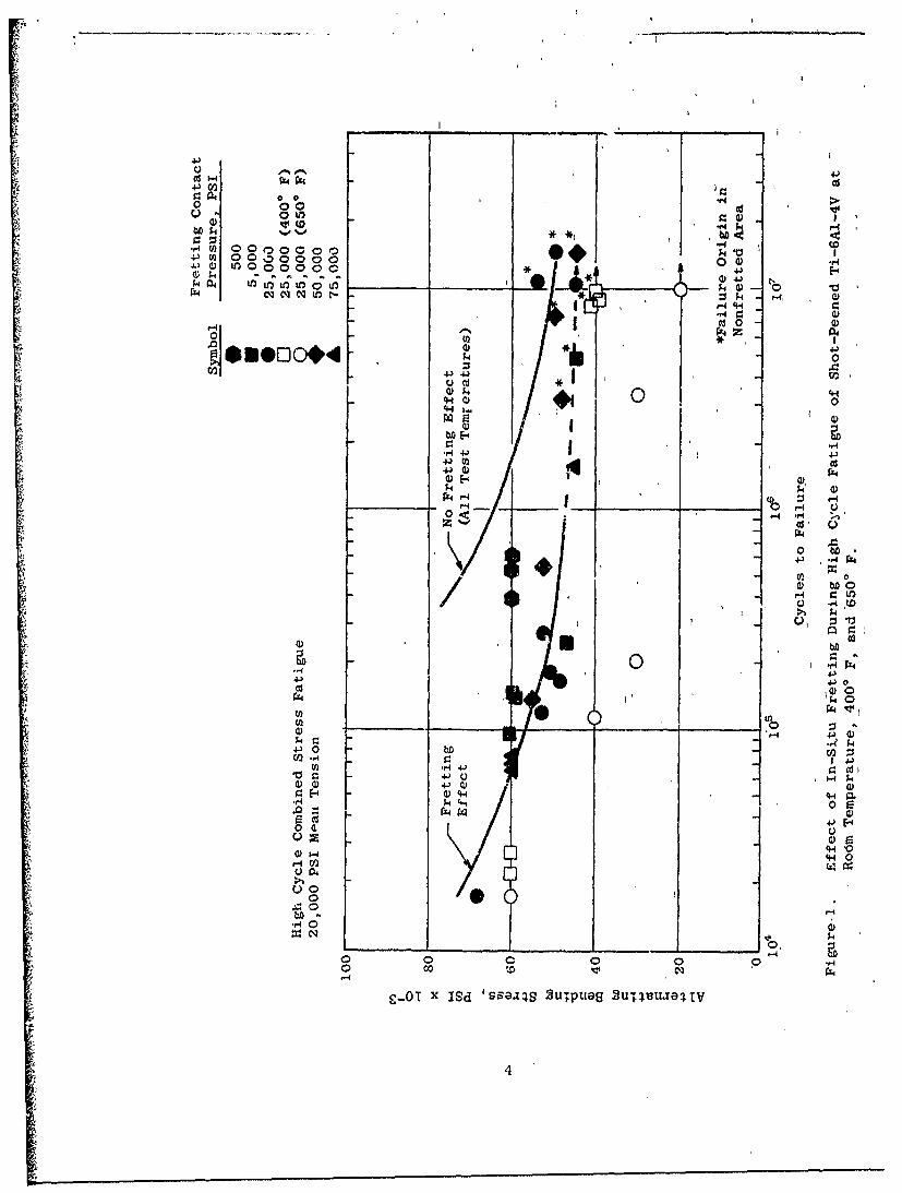
Figure I presents a summary of the results. These data indicate the fol-lowing effects (at room temperature, unless noted):
1. There was no degradation of fatigue life of the specimens at the non-fretted run-out stress levels of 40,000-50,000 psi (plus 20,000 psimean tension).
"2. There was a loss in fatigue life of nearly l1 orders of magnitude at60,000 psi bending stress (overs" ess region) due to fretting at5000 psi to 75,000 psi contact pressure, compared to nonfretteddata.
3. There was a loss of about i order of magnitude at 500 psi contactpressure in the overstress region.
4. At 4000 F fretting reduced the runout stress by 5000-10,000 psi;furthermore, the fatigue life in the overstress region was reducedby nearly 2 orders of magnitude, compared to nonfretted data.
S. At 6500 F the specimen life at overstress conditions was similarlyreduced; but, more importantly, the run-out stress was reduced by20,000 psi.
3 Preceding page blank
000 co0 00 0
.0z
.,.4 U) 0000000 0 C) 04 C
4j U) 00..DOOo0 10
0 a)
a) 00) 00 o04$4 (P "0
44 nW J~v Uq 0k 9U)t -, Q
Cd 0
4'4 )
0)0
'4-) Y) __
0 Q
V U .)
0 bD/) 0a) 0k 0
rP4 a0
0 ,0
4C0 0 0CV2..
U, 0
414
40 s-HCI~ '4-4
0 4
4.) 0-
C 0
00
C-0 xISd 'SesaiS 2u~pluaq 2u;~vujqIv
4 4
A series of interrupted fretting fatigue tests were performed at 25,000psi shoe-contact pressure and 60,000 psi fatigue stress (overstress region).Specimens were subjected to fretting fatigue for preselected numbers of cyclesprior t6 expected failure, inspected, then continued to failure after removalof the fretting shoes. The purpose was to determine at what cyclic life ter-minal fretting damage was incurred and whether the damage could be assessedby nondestructive fluorescent penetrant inspection. The fattgue results areshown in Figure 2, compared to the general data curves. They indicate a narrowthreshold between 104 and 5 X 10⁴ fretting fatigue cycles within which inexor-able fatigue damage developed. Fluorescent penetrant revealed cracks in theshort-lived specimens (none in the unaffected specimen) before each was sub-sequently tested to failure with no additional fretting.
2. TASK 2 - SLIDING WEAR FATIGUE
The purpose of this Task was to further the study of the effects of contactpressure and sliding wear displacement, using a two-step test in which the weartest was independent of the subsequent fatigue test. Shot-peened, forgedTi-6A1-4V fatigue specimens were first rubbed by Ti wear shoes under controlledlevels of contact pressure and stroke length at a rate of one fully reversedstroke cycle per second. Worn specimens were ther. subjected to high cyclebending fatigue under constant mean tension or to low cycle bending fatigueat A = 1 in both series. All tests in this Task were at room temperature.
The levels of contact pressure studied were 1000 and 10,000 psi in com-bination with stroke lengths of 0.5-1, 2.5, 5, and 10 mils (stroke length givenis one-half *he stroke cycle or the displacement in one direction of travel).The number of strokes of prior wear was 1000 for all tests. These results werecompared with previous Company-sponsored tests at 50,000 psi and a 5-mil stroke.
Figure 3 presents a summary of the high cycle fatigue test results againstthe background data curves. Under these high cycle fatigue test conditions, ithad been shown previously that wear at 50,000 psi pressure with a 5-mil strokedrastically reduced the high cycle fatigue life of the Ti at the nonworn run-outs~ress level of 40,000 psi (plus 40,000 psi mean tension). Furthermore, itdepressed the run-out stress level about 307. It was shown in Task 2 that:
1. Reducing the contact pressure (from the 50,000 psi of backgroundtests) to 10,000 psi with a 5-mil stroke produced scattered results
from severe to no effect, relative to fatigue life at 40,000 psialternating stress.
2. With a stroke length of 5 mils, the 10,000 psi contact pressure ap-peared to be a threshold level for wear damage, because at 1000 psicontact, 5 mils of stroke produced no fatigue loss.
3. Furthermore, at a contact pressure of 10,000 psi, it was shown thata 2.5-mil stroke did not cause damaging wear.
4. Finally, under a constant pressure of 1000 psi, stroke lengths up to
10 mils could be tolerated.
5
00
0 -;-4 Q A. . .0
4) a)~ 4)4 h1 0
0 H >10 d)4 U 3 N0cdi CQ .;46 . Q)4
S4- ) H lCHtr. 10 4)H 4. - Z0 (D 0 0. 40
Cd t 0 r 4,3 cd r.U
4J 0 0 04)
W 04. 0 3 IHO 0 0 0 P404C
I~r Fz4/244.P4
+30 04 0 0~
Cd 0
0 -r
4Ji *4-P 0
Cd 0
b. .4l
rn4 .14 -J .Ea~i -4i'4-4 >
S cd 0~i
00
.00c
*- 0 ,
6
14J0-40
U 4-4 4-
C) U
aco4)0 000laH)4L I k 4- U. )
CU- ) 0 r 0 4) )0)0 4.1) -n ) C.9 I0 o n 1 1 4 >)
k 0 H4 z C;rI0 k000 0. 0 BI: 04~it
k0 4*.4>OHO 0 V)~ z
(4-1 1 4
4) .9.4 ;-f 4.J
4-3 4.) 0 Cl~
41 a0 0 00 00 a 40 k 00000 04-11.1 : 00000 co 4-40 4-)
0 CD- ý4 1 H r~.v4
~U)CU) r.O
A____ C . '4~
11000*4 0 ;.
".4d C> 0E4
W0 0'4-4 r.
U (Dz0 r4".4 ý4 -0
0 10 Cd(D (1Hd bD 4 r=
F0 9: C.) *-4 .U)d
4--) H>
Q) (nC1 -4) 4 :0
rZ4 H4 k) H1 <4 0
W) OC 0 Q -V No . 41 0
4.) 0) - V)C 0)-' 0 4-
M- .'4 $4 ' U)1
00 C$.4 L): bblU(n"- -441 ti '4 4 .)
0c EI2. 04 0r.l0t QW 0 04- x
0 Cd m 0 0 ,4
0H 0) .. -4 '0 0,CEnO~e cU
-00C 9
".0 H00
0 0 0 0 0 '-4
01I X ISd 'ssaj4S 2u1puaa2 uT~j4Uj8~V
7
I~.
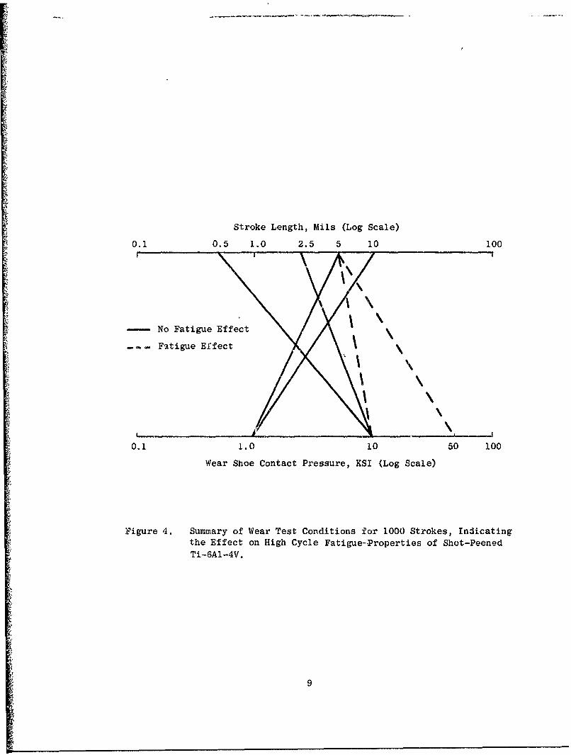
Figure 4 summarized these results in a nomograph form. Connecting lines depictthe specific test conditions of contact pressure and stroke length for whichfatigue-affecting wear damage did or did not occur within 1000 wear strokes.
Low cycle fatigue tests in bending at A = 1 were performed on specimenssubjected to wear under 50,000 psi and a 5-mil stroke. The results are shownin Figure 5. The imposed wear damage reduced the fatigue life by about 1 orderof magnitude at the bending stress level equivalent to 10 cycles for nonwornspecimens.
Stroke Length, Mils (Log Scale)
0.1 0.5 1.0 2.5 5 10 100
-- No Fatigue Effect
Fatigue Ef.fect
\
\.
0.1 1.0 10 50 100
Wear Shoe Contact Pressure, KSI (Log Scale)
Figure 4. Summary of Wear Test Conditions for 1000 Strokes, Indicatingthe Effect on High Cycle Fatigue-Properties of Shot-PeenedTi-6A1-4V.
9
f
'-4
C-1I
Cd
0~ ~P4 0
0 kzg
s-bDL 0a a)
"a4 0)
104-0
0~ 0,-
4) rA
0 00
54j
rx)1-4
,.D V-
4-)
00
00 (D c00
100
SECTION III
CONCLUSIONS
1. TASK 1 - STRAIN FRETTING FATIGUE
Shot-peened, forged Ti-6AI-4V subjected to fretting fatigue against itselfshould not be affected during operations at normal design stresses and below4000 F. At 4000 F a slight fretting effect should be expected, and at 6500 Fthe effect should be as much as 30% decrease in stress capability under thetest conditions of this contractual study. A substantial reduction in fatiguelife should be expected due to fretting during overstress conditions.
Increasing the interface contact pressure should not be expected to inhibitfretting during overstress fatigue conditions. In these cases fretting appearsto persist at the edge of the contact area between the static member and thedynamic member regardless of the nominal interface contact pressure.
Decreasing the interface contact pressure to 500 psi may diminish theeffect of fretting, but this pressure may be too low for normal componentassembly practice.
Surface appearance of fretting damage may be misleading and should not berelied upon for assessing the severity; however', fluorescent penetrant in-spection should be effective in detecting fretting fatigue cracks which pre-clude fatigue failure under continued overstress fatigue conditions.
2. TASK 2 SLIDING WEAR FATIGUE
Surface damage from sliding wear after 1000 strokes at contact pressureof 10,000 psi and 50,000 psi with wear displacement of at least 5 mils shouldbe expected to degrade by 407o the high cycle fatigue strength of shot-peened,forged Ti-6AI-4V. Severe, visible surface damage should he apparent.
Sliding wear at 10,000 psi pressure with 2.5 mils or less displacement
should not be expected t-) affect the high cycle fatigue strength. Only mildsurface effect shculd be tpparent.
At 1000 psi contact pressure, no fatigue effect should be expected withSwear displacement up to 10 mils for 1000 strokes, although substantiated visi-ble wear effects may be apparent.
The low cycle fatigue life at bending stress equivalent to 5 X 10⁵ cyclesshould be expected to be reduced by one order of magnitude due to wear damageat a conb.ct pressure of 50,000 psi with 5 mils strike.
11
SECTION 11
TECHNICAL PiOGRAY
1. BACKGROUND
Modern aircraft gas turbine engines represent an extensive commitment toTi alloys, whereby their effective performance depends on methods to protectthe metal from wear damage. The technical program plan for this contract isbased on a background of continuing studies at the General Electric Company,concerning wear phenomena and the development of protection methods for struc-tural materials such as Ti alloys (References 1 through 8). The subject ofTi wear has been extensively treated in the scientific journals, and severalcomprehensive binliographies are referenced (9 through 14). Very little ofthe published information deals directly with aircraft turbomachinery. How-
ever, there are basic wear processes common to all machinery. These are dis-cussed in the following section, with particular emphasis on fretting fatigue.
2. DISCUSSION OF WEAR PHENOMENA
a. General Wear Processes
Wear has been defined as the progressive loss of material from rubbingsurfaces. The -ate and effect of this removal depend upon the characteristicsof the materials involved and the environmental conditions. For purposes oflurthering this definition, four main types of wear are commonly recognized.
* Adhesive Wear - the most common and difficult to control. It resultsfrom the welding or adhesion and subsequent rupturing of contactingasperities on a surface. It is particularly severe between slidingpairs of metals which are chemically similar and/or mutually soluble.Adhesive wear is closely related to surface friction in such a waythat an incriase in frictional forces generally causes a large in-crease in resulting wear.
• Abrasive Wear - caused by the cutti.;g or plowing of one surface by aharder surface. The harder material may simply be a harder alloy orit may also be an oxide, carbide, work-hardened particle, or otherforeign material. Erosion may be considered a form of abrasive wear.
* Fatigue Wear or Surface Fatigue Wear - commonly encountered 4ia rollingor sliding contact, where high localized forces are cyclically imposedon a small contact area. Thi.s type of wear occurs most commonly ingears and bearings.
Preceding page blank
13
9 Corrosive Wear - results from some type of chemical reaction with theenvironment. It may be due to general oxidation, chemical fumes,humidity or combustion products, and may also be inadvertently causedby ingredients in lubricants. Corrosive wear usually exists in combi-
nation with one of the types of mechanical wear noted above, encour-aged by frictional heating and the continuous removal of natural
protective oxide.
b. Friction and Wear
Friction is not a form of wear. Furthermore the frictional forces andcalculated friction coefficients (p) of sliding surfaces have not been shownto have a consistent relationship to wear processes or rates. In some situa-tions high p relates to the occurrence of adhesive wear or other interference
to sliding caused by accumulation of debris. Ti is such a case. Tungsten car-bide, on the other hand, slides with high L but usually has a very low wear rate.Lubrication produces low friction generally, but this relates to wear only inthe sense that the wet or dry film separates the two surfaces, thereby prohi-biting wear. Friction may increase when wear is in progress, but, in general,the absolute value of • does not relate to the wear process or its severity.
c. Forms of Wear
The forms of wear are those names given in practice to describe the ap-pearance of a particular worn surface. There are several common forms includ-ing fretting, sliding, galling, and others. Fretting is the term most oftenused to characterize the form of wear observed in Ti components. It describesthe cosmetic result of wear caused by and limited to the smaller amplitudes of
cyclic displacement of contacting surfaces. This differentiates it from large-* displacement oscillatory or undirectional sliding wear. There are two definite
forms of fretting wear associated with aircraft engine components. They are:
a Classic Fretting - the form of wear limited to contacting surfacesnot intended to have relative motions (e.g., bolted compressor di~cflanges). The displacement therein is extremely minute, resultingmainly from alternation of mechanical strain in one or both surfacessubjected to operational vibratory stresses. Classic fretting isoften termed fretting corrosion because tee wear mechanism is chieflythe conversion of basis metal to an oxide. With Ti, the rutilespecie of Ti oxide is produced. This reaction is fostered by the
high temperatures that asperities attain when subjected to friction.Pits acting as fatigue stress raisers are formed as the result ofcorrosion. Adhesion is an additional factor, and abrasion from thedebris trapped in the interface promotes further wear in manymaterials. The corrosion product may compound the stress situationdue to the volume increase associated with the phase change. Classicfretting is insidious by reason of its covert existence and may pro-duce unexpected fretting fatigue in components operating withinnormally safe design stress limits.
14
* Common Fretting - a form of wear charoterized by less restrictedsurface motion than classic fretting, a motion that can includeperiodic separation. Debris and foreign matter may contribute toabrasive wear but are not necessarily entrapped. Blade dovetailsand disc groove pressure faces are specific areas of occurrence.The mechanism of common fretting is usually more mechanical thanchemical and may produce galling. Fatigue failures may result fromthe stress concentrations produced by fretting damage in applicationswhere only moderate vibratory stresses are present. In other appli-cations, loss of dimensional fit may be the critical result.
d. Results o.f Wear
While the mechanisms and forms of wear are important in understandingthe phenomenon (and there are many other factors including material properties,states of stress, and ei.virenmental conditions), it is the final results ofwear that are of immediate concern. The principal result of wear is loss ofmechanical functionality by:
"* Dimensional changes
"* Fatigue failure
The gross result of fretting is normally fatigue failure brought about by sur-face damage in conjunction with normal or transient high stresses in a compo-nent. Visual assessment of fretting mildness or severity is at present incon-clusive by itself, in that the presence of more cr less fretting debris on amacroscopic examination is not necessarily relevant to the loss of surfaceintegrity. It is the state of stress acting in conjunction with stress raisers(pits, tears, cracks) which may be microscopic, that determines the actualfatigue propensity.
This program was based on a study of the fretting wear r~gime where fatiguelife was the absolute measure of wear severity, but where evaluations includednondestructive examination of surfaces for clues to severity other than visualassessment. Fatigue loss being the major concern, two specillized tests havebeen used for evaluation of fretting and the merits of surface protectionmethods. The methods were developed to evaluate classic fretting and commonfretting as separate entities under conditions closely simulating engine service.Each is ultimately a fatigue test with the fretting produced in the classic form(in situ) or by prior fretting independent of the subsequent fatigue test.
3. WEAR AND FATIGUE TEST METHODS
a. Requirements
Utilizing meaningful test procedures is of prime importance in aircraftengine application because past experience has shown that generalized friction
15
and wear testing do not adequately simulate the complexities of engine operation.Furthermore, a key factor in the test technique is the means by which wear ismeasured. While the quantitative measurement of surface effects and materialloss can be obtained by several techni*ues ranging from visual assessment ofdamage to holographic comparison of dimensional changes (and may include pro-filometric tracing, area and volume measurement, weight change, radioactivetraces, friction changes, and others), the primary objective in wear studiesmust be to assess wear qualitatively by measuring its effect on tangible pro-perties, mechanical or physical, which most seriously affect the functiona]ityof a particular engine component. Flange and dovetail fretting both consti-tute fatigue-limiting situations, so that the paramount measure of wear is itseffect on fatigue life.
b. High Cycle Strain-Fretting Fatigue
This test technique was developed for evaluating the fatigue of Ti-6AI-4Vin the presence of fretting around the flange bý,lt holes of compressor discs.The state of stress existent in a bolted rotor jLint consists principally of(1) a mean hoop stress, (2) high cycle bending stress, and (3) contact stress.
The test is performed in a modified four-point bending fixture, in con-junction with a mechanical fatigue shake table, as shown in Figure 6. Acharacteristic of the fixture is that it provides a constant bending momentacross the specimen gauge section, allowing natural stress concentracion tobe effective. The horizontal load spring applies the mean tensile stress,while the alternating strain is induced by high cycle fatigue bending. Thethird stress component, from zhe bolted shoes, is monitored by the use ofstrain-gauged bolts.
In the test, the fatigue benaing stresses produce minute alternatingstrain motion of the Ti specimen against a mating wear shoe. This causesfretting, the severity of which is measured by the change in fatigue life ofthe specimen.
c. Sliding Wear and Fatigue
Centrifugal forces in fan and compressor discs, combined with the contactstress on the dovetail pressure faces, produce a low cycle weur and fatiguesituation related to engine power excursions. Two major changes in enginepower which occur during a normal mission are takeoff and thrust reverse.Wilh each increase in engine rotational velocity, hoop stresses cause thediuc to enlarge circumferentially. The resultant spreading of the slots a!-lows the blades to slip outward in response to centrifugal force, creatingcyclic sliding wear under high contact loads in the dovetail pressure faces.
A test to simulate this condition is a two-step method involving (1)the wear of a fatigue specimen under high contact pressure, followed by (2)fatigue of the worn specimen. The wear apparatus is showr in Figures 7 and 8.
16
K % -1
I C)
C;)
414
ANV
ri)
17'-
4'-1
-4
a)0
C4 .)
a)0
FIFF I, ý l Kl,ý!;("e!V.)
18
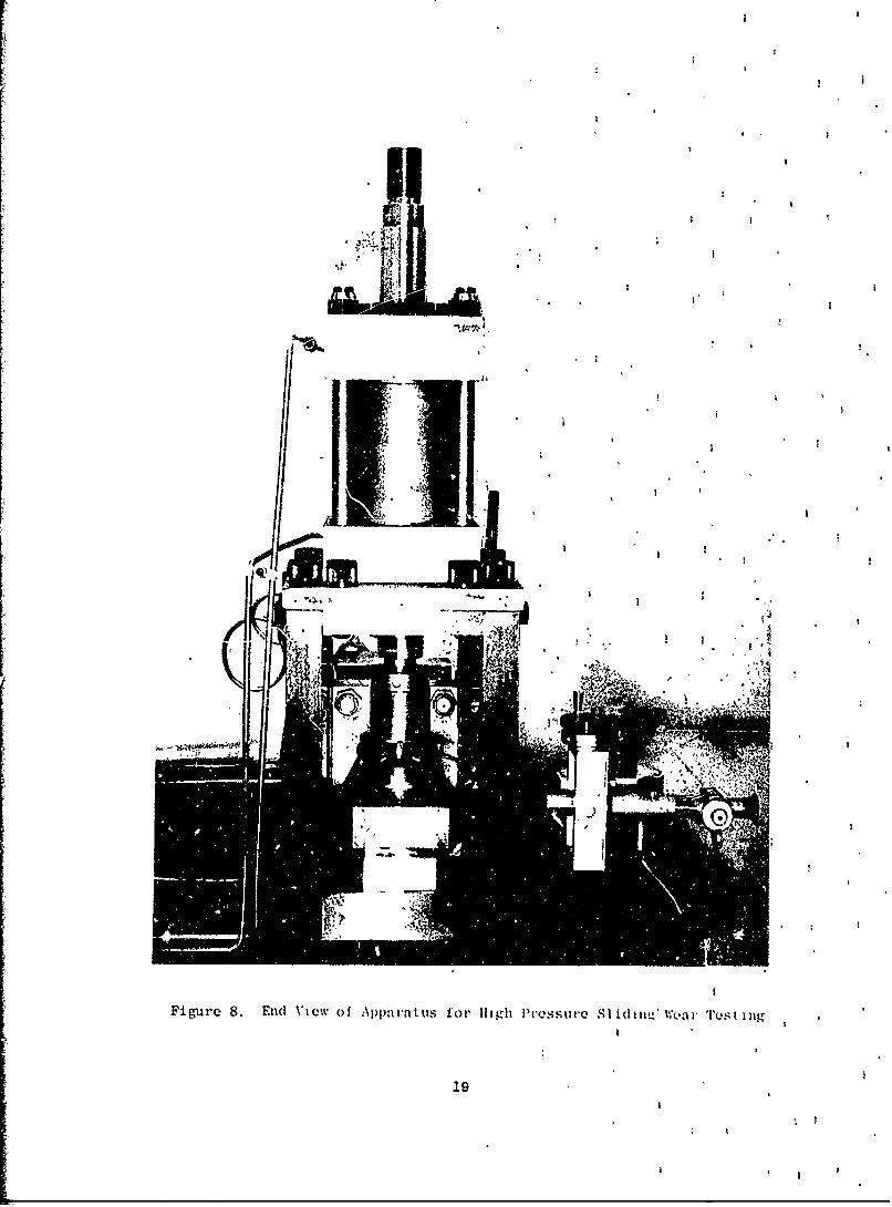
Figure 8. End Vieow of Apparatuhs I'ol' 111911 Pressureo SI hidi %VeWa r Tlus i i ng
The test specimen is mounted in the carriage fixture which is hydrauli-cally actuated. The shoe is held in the fixed base block of the apparatus.Pressures to 80,000 psi on a 1/4 X 1-inch contact area are possible. Thesubsequent fatigue test is four-point bending in either the HCF or LCF mode.
4. CONTRACTUAL WORK STATEMENT
a. Abstract
The contractor shall establish conditions which produce fretting fatigue
damage of titanium alloys in AGT engines.
b. Detailed Description
1. Purpose - The purpose of this effort is to define and establishconditions under which fretting fatigue of titanium alloys should
be expected in aircraft gas turbine engine compressor applications,in order to permit establishment of appropriate test conditionsfor subsequent evraluation of fretting-preventive coatings for
titanium.
2. §s - The contractor shall conduct the investigation discussedbelow for the purpose of defining and establishing a range ofenvironmental conditions that produce fretting-fatigue damage intitanium engine applications and define appropriate levels ofthe variables involved. Appropriate tests for evaluating fretting-preventive coatings shall be recommended and verified.
3. Effort - The forms of fretting associated with engine componentsare (l) classic fretting, limited to contact surfaces not intendedto have relative motion, e.g., bolted compressor disc flanges; and(2) common fretting, generally found on less restricted surfacesthat may undergo periodic separation, e.g., blade and disc dove-tail pressure faces. Appropriate fretting fatigue methods forevaluating classic and common fretting are strain-fretting fatigueand sliding wear/fatigue, respectively. Therefore, the effort
shall be organized into two appropriate tasks, with all testsemploying uncoated, shot-peened, forged Ti-6A1-4V alloy specimens.
(1) Task I - Strain-Fretting Fatigue
The parameters of contact pressure, tensile load, relative motion, andmetal temperature shall be evaluated in strain-fretting fatigue. The followingcontact pressures shall be applied, using strain-gauged shoe assembly bolts:
20
1. 75,000 psi shoe contact pressure at room temperature
2. 5000 psi shoe contact pressure at room temperature
3. Spring-loaded shoe contacting the specimen er, a 1-pound load,
at room temperature
4. 25,000 psi shoe contact pressure at 4000 F
The specimens shall be subjected to tension-bending fatigue at 20,000
psi mean tensile stress and 60,000 psi alternating stress, with relativemotion calculated from strain relationships.
Rating of visual and metallographic appearance shall be recorded to estab-lish any correlation of visually observable fretting effects with absolute
effect on fatigue. Radioactive Krypton methods and other techniques as appro-
priate may be employed to aid inspection and correlation.
The scope of these tests may be extended to include other temperaturesand stress levels as appropriate, if indicated by results above and within the
limits of time and funds available, upon approval by the AFML Project Engineerand AF Contracting Officer.
(2) Task 2 - Sliding Wear/Fatigue
This task shall include a two-step test method, evaluating the effects
of contact pressure and relative-motion wear on subsequent bending fatigue,
under the following conditions of wear:
1. First, employing a 0.005-inch stroke under 10,000 psi contactpressure for 1000 wear cycles, followed by high cycle bending fatigue
tests, then:
2a. If fatigue loss is observed in 1., less severe conditions including:
Wi) 0.0005-inch stroke under 10,000 psi contact pressure for1000 wear cycles, and
(ii) 0.005-inch stroke under 1000 psi contact pressure for 1000
wear cycles, followed by high cycle fatigue tests; or
2b. If no fatigue loss occurs in 1., more severe conditions including:
(i) 0.005-inch stroke under 20,000 contact pressure for 1000wear cycles, and
(ii) 0.0005-inch stroke under 20,000 psi contact pressure for 1000
wear cycles, followed by high cycle fatigue tests
3. In addition, the effect of a 0.005-inch stroke under 50,000 psi con-tact pressure for 1000 wear cycles shall be evaluated by subsequent
low cycle bending fatigue. (It will be necessary to first establish
a baseline of low cycle fatigue.)
21
Items 1 and 2 above shall be conducted in high cycle bending fatigue under40,000 psi mean tensile stress at 40,000 psi alternating stress. Item 3 shallinclude baseline low cycle bending fatigue test data to be determined atA = 1.0, then evaluation of fretted specimens at an appropriately selectedstress level. Surface and metallographic appearance of fretting shall berated for comparison with fatigue results.
(3) Task 2 - Amendment
Additional tests under Task 2 shall be conducted as follows:
1. Employing a 0.002- to 0.003-inch stroke under 10,000 psi contactpressure wear cycles, followed by high cycle bending fatigue
2. Employing a 0.008- to 0.010-inch stroke under 1000 psi contact pres-sure for 1000 strokes, followed by high cycle bending fatigue
22
SECTION V
EXPERIMENTAL WORK AND RESULTS
1. SPECIMEN PREPARATION
Figures 9 and 10 illustrate respectively the specimens for high cycle andlow cycle fatigue. Figures 11 and 12 show the two types of specimens withtheir respective wear shoes used in conjunction with the fatigue specimens.All specimens were prepared from annealed a-S processed TF39 flade forgingshaving mechanical property requirements of 130,000 psi minimum ultimate tensilestrength and 120,000 psi yield strength. Low-stress grinding techniques wereutilized for primary surface finishing; then, the fatigue specimen gauge sectionedges were hand radiused to 0.050 - 0.060 inch. Finally the specimens were shotpeened to 0.006 - 0.008 A2 Alman intensity using size 110 steel shot (S110) with120% coverage. Specimens were rotated during peening for gradual, uniformbuildup of stress to prevent warpage.
The fretting and wear shoes were also prepared from flade forgings. The
shoes were shot peened only on the wear test surfaces.
2. TASK 1 - STRAIN-FRETTING FATIGUE TESTS
a. High Cycle Fatigue Apparatus Calibration
The HCF apparatus previously shown in Figure 6 consisted of a modified four-point constant moment bending fatigue fixture mounted on a S'nntag SF-lU Uni-versal Fatigue Machine. The fixture performed bending fatigue combined with amean tensile stress.
A calibration specimen was instrumented with six foil-type strain gaugesas shown in Figure 13. The specimen was aligned in the fixture by monitoringstrain gauge deflection under application of static axial preload. The axialforce was monitored through the precalibrated pull bar load cell and withspring deflection constant. Specimen preload was applied on the basis of P/Astress desired.
Data relating specimen bending stress versus fixture displacement (ampli-tude) under dynamic conditions wire obtained and a master calLbration curve pre-pared. A light-beam type recording system was used to record dynamic strain.True stresses were calculated from the 900 rosette formula using 15.95 X 10⁶psi dynamic modul= of elasticity and 0.34 Poisson's ratio.
The specimen geometry was shown to have an edge stress concentration ofzero in bending, and a concentration of Kt = 1.1 in tension. Therefore, undernormal surface conditions, the specimens would be expected to fail at one of
the four corners of the minimum cross section, unless predisposed to locationson the major surfaces of the specimen gauge section by greater Kt induced fromwear damage.
23
0)
0
00 b0
00 0
CDo
CU 0)
Cd
r44
0)
04-
000
24-
44
-cq
ci)
A Cd
>1)
~oto 0G
000O 04-
0000 H 0) r~4
. t3If 0*e-4
Cd
r.r
0
H0 0
*I. 00
F-J
cq Nc
00)0
HO
r 25
Cd- 0 0
0 -q
0 tA
-H cd U)
- 0) )
Cr2
0riU) 4J
- ~ p4.)4
-- r
4.) r-4- Cd0)
;4 4.)
cI1m0)
it f0
26'.0
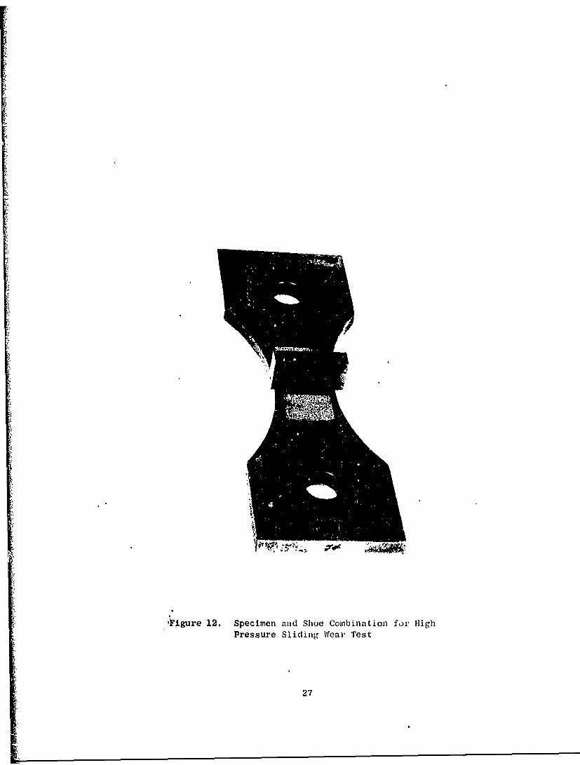
lFigure 12. Specimen and Shoe Combination for HighPressure Sliding Wear Test
27
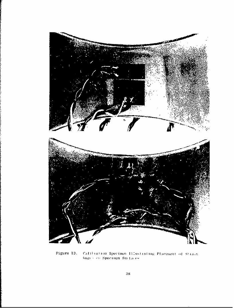
Figure 13. C.01,1, IlU oll SptecinlivnIIimiIi alPwm~i ' ~(zag ! Spuce iIune Szi Iatk
28
b. High Cycle Fatigue Test Results - Room Temperature
In this test, the fatigue bending stresses produce minute alternating
strain motion of the Ti specimen surface against the mating wear shoes. Thisresults in classic fretting, the severity of which is measured by the changein fatigue life of the specimen. The variable in this test series is theshoe contact pressure which might be expected to influence the severity offretting under (1) very high surface contact pressure therby restricting thebending and resultant strain motion at the interface, or (2) such low surface
pressure that significant fretting might not occur. Figure 11 illustrated aninstrumented specimen, a set of wear shoes, and the pair of internally strain-
gauged clamping bolts. Specimen strain gauges were attached withir 1/32 inchof the shoe contact edge where reported bending stress was monitored. Thefretting fatigue apparatus containing a specimen with bolted-on wear shoes forhigh contact force was shown in Figure 6. Figure 14 illustrates the specimenassembly with precalibrated springs holding the wear shoes for 500 psi contactpressure.
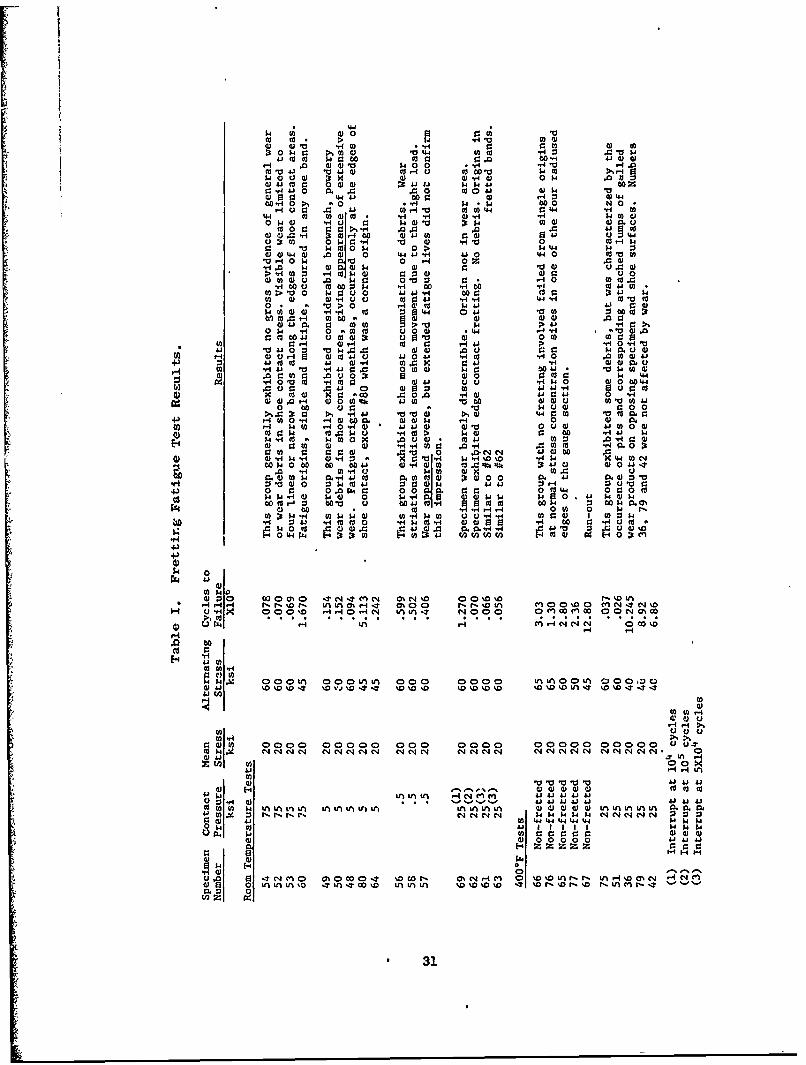
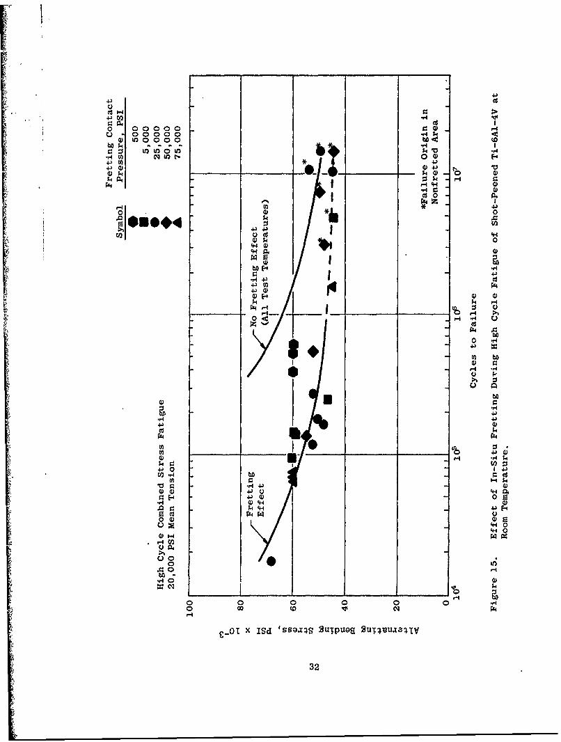
Tests under 75,000, 5000, and 500 psi shoe contact pressure were performed.The results are compiled in Table I and plotted in Figure 15. The S-N curvesare presented in conjunction with baseline nonfretting and fretting fatiguedata for 50,000 and 25,000 psi shoe pressures from background tests conductedby the General Electric Company.
Several effects are evident from these data. Specimens tested with nofretting define a 107 cycles run-out stress of 50,000 psi alternating (70,000psi total including the mean tensile stress). Specimens with fretting shoesclamped at 25,000 and 50,000 psi nominal surface contact pressure, and testedat stresses in the vicinity of the baseline run'out stress, showed no loss incyclic life capability. Fretting wear was apparent in the contact area, butfailures occurred adjacent to the fretting bands. Failure always occurred out-
side the area of contact, and 8-15 mils subsurface, presumably below the ef-fective shot-peened surface layer.
However, at slightly higher alternating stresses represeating possibleoverstress conditions, a substantial loss in cyclic life capability occurreddue to fretting. The effect was clearly fretting fatigue in that all specimensfailed within the narrow fretting band found at the edge of the shoe contactarea. All such failures originated at the surface in the area damaged byfretting.
In the original Company-sponsored studies, there was no significant differ-ence observed as the result of varying the shoe contact pressure from 25,000to 50,000 psi. The current tests under 5000 and 75,000 psi shoe contact pres-
sure likewise produced no difference. The fretting fatigue loss wis dependentupon the magnitude of relative strain motion at the specimen/shoe interface andindependvnt of the nominal interface contact pressure in the range studied.
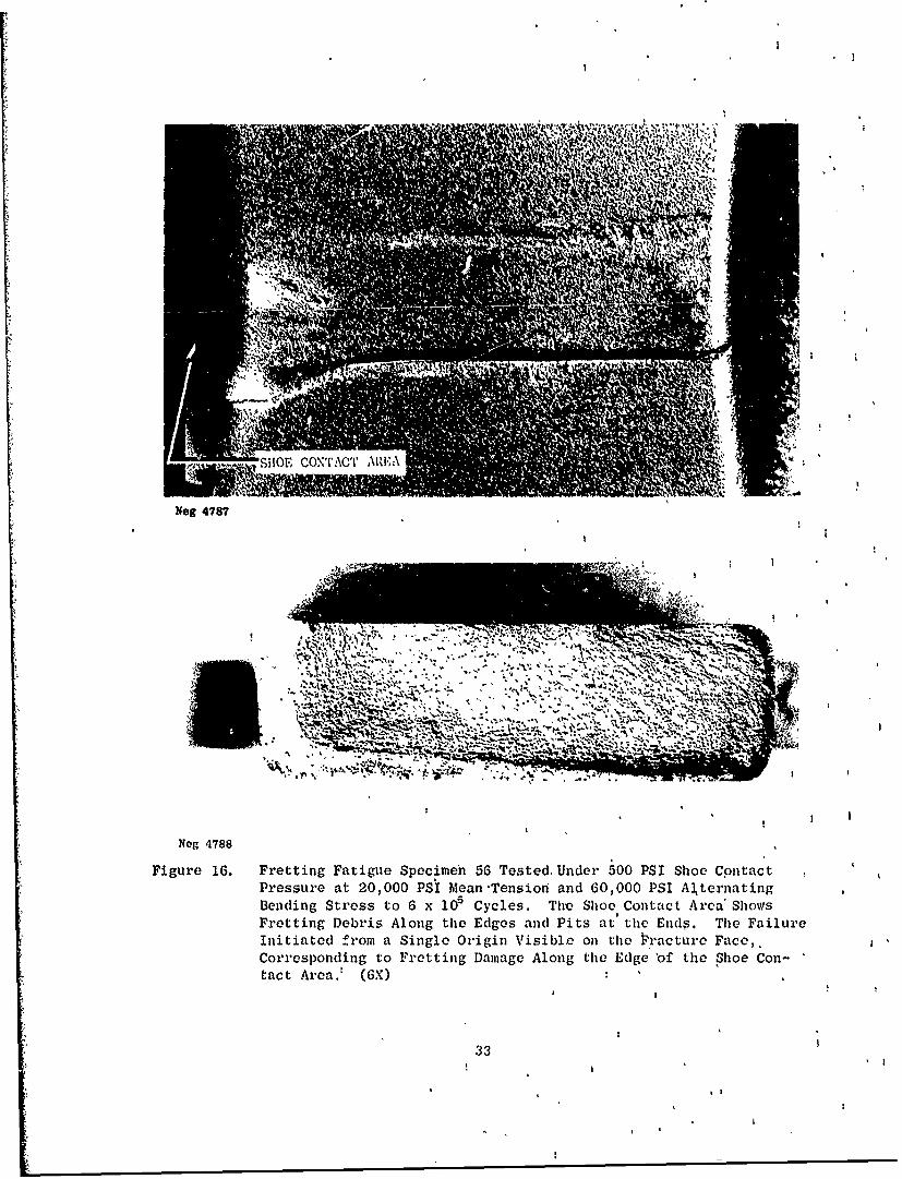
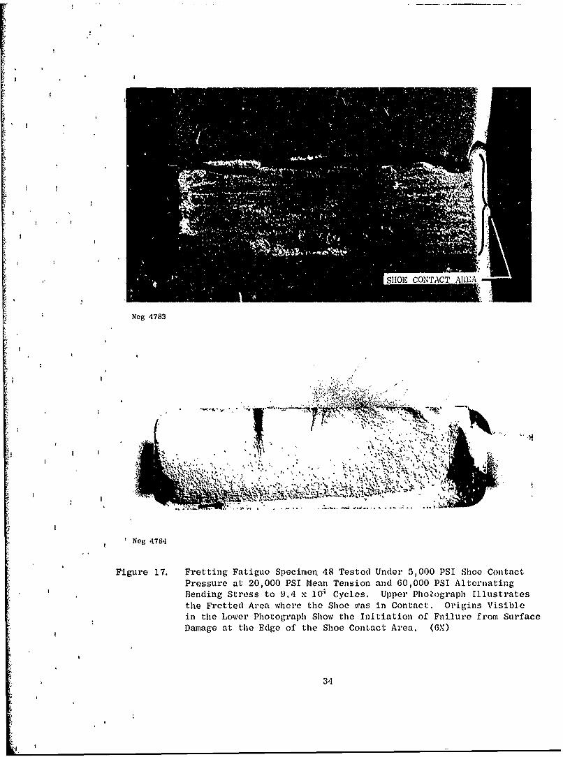
Figures 16, 17, and 18 illustrate the typical surface appearance of frettingfatigue specimens tested under 500, 5000, and 75,000 psi, respectively. Visually
29
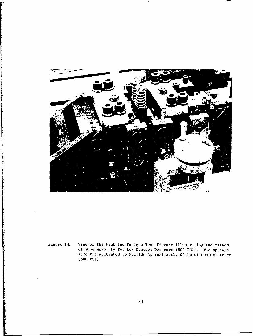
FigiVre 14. View of tile Fretting Fatigue Test Fixture Illustrating thle Methodof Shoe Assembly for Low Contact Pressure (500 PSI). The Springswere Precalibrated to Provide Approximately 90 Lb of Contact Force(500 PSI).
30
P..
0 p0. a .. .:3 C03 c c bo .40 r.- .0 W001 0) a)
.'4-0 0) .) 0 W.00 004- 10 HW300 4.1 coo -H .- 0 0344.40 "0.0k 0 W*a)4* kjk 000 W O.
= 40410 .m 4 %3I03 0034-4 04)-4 4a)4 0z 93 31 44 ..1 r. 0 0d (V 544to 0i0 1 0I-H $4 .04 b0 .0N0
H330. u 0 co.SO 04V to 003W 0 4.4 ~ .04 Cd 0) 0)to - - .4 1.4 to0003$440 W 00 0H u.4J4 4 0 40 .03 d) ) 9 t
to 0k r. gC 1- 0 .- 4 C ~ 4.003
" "0l. W 03 0 p 03 0 W30 04.004)03404 -0kW 00 0 4404310 0 0 0
V303030 W0 a 1 0 0 - * 0-S 030.
0.so 0 u 4 W 0100 .. o 14 0 totv .m > 0 0 W0u k O 04-.41 000W :1 ~ 4. $.403l 0) 0) - u00 t 0 4.i .14y4 44 -H ca a00 o0V>0.r- (V co~ .4 4. 41 00$4 -H0 .4..4 co 0134.4 0 4J 10 0 :3 o o
to.0- 630 003 W3 00W .0 0;3.0 0 030 > 5. 4 41 -0C>.
0Ok - 9, U- 3 0003 .44 .- 4r . 4).000000W4J 140)3 u~ 13 03 0 0300
41o0 4o 04.' .40 U 4rs0 W M U0)1 4.JO 4.' 03..vi U4 0 a.0HK 04. 030W0.0
1-4 03 . 0 r. .4J0 0 0l303 0O 04.~ 003k430H3 .010 0 .0H 0 m V.004 uW0 0. 0 4bo
u 4 0 400 041-H u0000tr 000 4 41 9: 41 0 H
0 0o 0 5400 000
4-)3~. 1-403000 m 03054 .-4 003 .i-S 503 ý -0 .140 * 4.24) 40 4) 0003 0) Ato0300m0Wk 0.0a40 .0) M0 V 00 :2 qC:
E- . 3s 4 - 440t0 C: .00 3 v4- 03 m0 :9~00
(a 0k.. r3. 90 10 0 0 J>N03A00 b05 4 000 00 00 4- 0) 4400 0) o i.9 4% . Dt41 4) 0 41 11
.0 034U) 5.H0 Q0WW 03.0u4) m W M0 0541-a 04 o0o3k 1 ) 4.4. 0 0o10) 5
4.5 0 0 0$&0 00 0. 00 0 amC30 144 0r.000oW03- i 00 V4 a . .4)-4.-W 4 0W 0 1. 4 0)
60 to .- lW bo0 0 k0.-S 0 4 a m 0 W4 :3. 5003kQP40~ d) 00 0 d -HJ0. H00 0 0 0 0k0N
03 k...4 0H3? W5W03 H$ 0 u u 03 00 -H-- 03003W 1 054.- 4 0 Cd a)W g.40 .4J 0. 0330-. 0 0 V4 * a a 9
0 W CX4 :9 Dt ( 003 0n .0003%
$4S 0!P'4 Ai4
0 1 0 H q o ý o -t-t.5 O'c.' 00'.MI0oo' ý Di c % l)NI C4%U- .4 x 0' No H H C0.-SN usus4n T NO 0( Cn IDM00 C)0 N0%00
>ý. to . .. . .
60
$4 00OLfn 000'f5'r 000 0000 n IAOLA co0:~W341 % %.D' %0 * %0 T %0%0%0 1O'0 %0 %D D OU5.4 ýo% T-rI
03 000000000 o 00 000 -
W t . i 0 NC'J N' 4c'J Ne' N '4eq5 e C14 04 N N C4~'N C-4N e 0'4 N 14-.7 0034.4 .7 n -4
4-i -~4-51 t0cc
00- 3. . I ý ý 414.34.5A.3 4. 4.3 4.003MW0 1 kn nL n L ML LA4LL f5t in n n n n fcIJ 033303 WA5. 0.0.0.n n A4J m3± N I5ý N C-4N k- k W5W 54W C-C4 N N C4 0q 0 0a0 toJ 4.4 44 4.4.44 4 54k k05 01 4 4.5 1 1 11 1 141400. kut :C :V 03000) 0300W3 03 020 000 0414.
54) C-4U 0.0N 0 0.c-cb o'00o0-T %D COt- . C-e4 14 M 0 '%D%0 Lnt-f N f5&-SH00De' i-S NC*4
00 0
* 31
4.)
CU1d
0 00000 ~0. 00000
4-)Cf 4.)
P44
054 0
0 0I
4. 4.)CCU
P4
CU
o r4
C)
4J0 U110 r. -H44.
4.) 0F4 4- - r41
0 ~ ~ P W -4 .. 4
40 a).
CH 000
00 02 r
0 10 P
C-01x Is Issl~sBu~pes 2T~vua ~H
320
Neg 4787
1-IT-
Neg 4788
Figure 16. Fretting Fatigue Specimen 56 Tested. Under 500 PSI Shoe ContactPressure at 20,000 PSi Mean Tensioii and 60,000 PSI Al~ternatingBending Stress to 6 x 10ý Cycles. The Shoe Contact Area' ShowsFretting Debris Along the Edges and Pits at the Ends. The FailureInitiated from a Single Origin Visible on the P * acture Face,.Corresponding to Fretting Damage Along the Edge 'of the Shoe Con-tact Area.' MG)
33
SHOE CONTACT AREA
Neg 4783
4Neg 4784
Figure 17. Fretting Fatigue Specimen, 48 Tested Under 5,000 PSI Shoe Contact
Pressure at 20,000 PSI tMean Tension and 60,000 PSI Alternating
Bending Stress to 9.4 x 0"I Cycles. Upper Phot'ograph Illustratesthe Fretted Area where the Shoe was in Contact. Origins Visible
in the Lower Photograph Show the Initiation of Failure from Surface
Damage at the Edge of the Shoe Contact Area. (6X)
34
ShoeContactArea
Neg 4789
I.
,*j. , ..- q.....Vv,;
Neg 1790
Figure 18. Specimen 60 Tested Under 75,000 PSI Shoe Contact Pressure. UpperPhotograph Illustrates the Mild Appearing Fretted Area where the
Shoe was in Contact. Origins Visible in the Fracture Face Show
the Initiation of Failure from Surface Damage. Detail of the Wear
Damage is Shown in Figure 20. (6X)
35
the fretting was more evident on the lower-pressure specimens, and it extendedover more area under the shoes. Lesser restraint of specimen bending underthe lower-pressure shoes apparently permitted more relative motion from bendingstrain and Poisson effect throughout the interface. Butz at 75,000 psi contactpressure, bending restraint prohibited large strain motion except in a finiteband along the edge of each shoe contact area. It is this fretted band at theedge of contact where fretting-related failures always occur on test specimens.No specimen failed under a shoe between the fretted bands, and no fatigue crackpropagated into the contact area.
Except for a moderate increase in the life of the specimens fretted under500 psi contact pressure (and regardless of the appearance of more apparentfretting at 500 and 5000 psi), the combination of strain -:otion, fatigue stress,and mean stress produced fretting damage of significant magnitude in terms offatigue life reduction under the five levels of contact pressure which havebeen investigated.
Figure 19 (Specimen 52) illustrates what was found to be the typical metal-lographic appearance of the fretted specimens. Figure 19A shows the mild-appearing fretting wear surface. Figure 19D shows the lip of the fracture faceand a fretted depression on the adjacent wear surface. At the end of the fretteddepression there is a shear crack. The depression contains wear debris. Figure19C is a section through the fretted area at the other edge of the contact area.Fretting debris prevented good adherence of the Ni-plate applied for metallo-graphic preparation, but the fretted depression is evident. Surface shear cracksare visible as is an incipient fatigue crack, characterized by its nearly verti-cal direction. Note the fatigue crack propagated from a more oblique shearcrack. In the metallography of fretted specimens, the oblique shear cracksfrom which fatigue fracture initiates were only observed in the locations shown,i.e., corresponding to the fretted bands described previously. None occurredany farther under the shoes.
Note that the direction of the shear cracks is toward the contact area andaway from the applied bending stress. This pattern has also been consistent inthe fretted areas observed. The cracks allude to the shear stresses resultingfrom relative sliding motion of the surfaces. The cracks develop in tension,i.e., when the specimen is bending away from the shoe. The benefit of shotpeening as a deterrent to fretting, relates to the formation of a compressivesurface layer which tends to offset a portion of the tensile shear stress.Lubricants would also act to deter fretting by reducing the friction coeffi-cient, thus lowering the shear stress.
Figure 20 is a series of SEM photographs of Specimen 60 illustrated pre-viously in Figure 18. Figure 20A shows a macrophoto of the single major origin.Figure 20B shows the origin in perspective with the fracture edge and the dimpledpeened texture of the specimen surface (part of the shoe contact area duringtest). Successively detailed views of the origin in Figures 20C and 20D revealno readily discernable primary site of failure. Nonetheless, they show thefretted band from shoe contact along the fracture edge. In the center view it
36
' ,, .,,,• * Shoe Contact Area
Ix
Mtount 6901, Neg G 6300 1000XC
4785, 6X
A
Figure 19. Composite M~acro- and M~icrophotographs of Specimen 52 After FrettlThe Metallographic Sections Reveal Oblique Shear Cracks and WeariShoe Edges. An Incipient Fatigue Crack is Visible in View (1,1from Multiple Origins. SEM Photograph~s of Such a Wear Surface a
1W -
Mon 691 Ne -28 OO
.-. -D
4785,6X 485, X 476, 6
.~ 0 B
fterFret ecmen52 fterFretin FatgueUndr 75000PSIShoeConact
and ~ ~ ~ ~ ~ ~ ~ ~ ) Wea Shear CrcsadWa isi*h anso otc fteFtFiew~~~ ~ ~~~~~~~ (I Viil nVe .TeFatr ufc eel aiu alr
Surface ~ ~ a. SuhaWa ufc r hw nFgr 0
Pag 3
_ -~ -T,
\4
Mon 6901,- .e 28 OO
~D
4785, 6X4796, 6
* -~ B
ecimn 5 Aftr Fettig Ftigu Uner 7,00 PSISho Conact
Sha CrcsadWa isi-h anso otc fteF~tn
Nisblein iewC. he ratur Sufac Reeal Ftigu Falr
Such ~ ~ ~ ~ ' a erSraeaeShw nFgr 0
~ Page 37
Peened
Fretted ,
Surface
Edge '*Fracture ~Face
SEM 66E, 25X', 450 x 308B
Edge-:i
C
Neg 4790, 6X
Figure 20. Composite SEM and Macrophotographs of SpecisiSpecimen Surface was Illustrated PreviouslyFracture Face in the Origin Reveal the SurfaFigure 19 Previously Illustrated Typical Met
Page 38 ~,Typical. Shot-Peened Surface in a Nonfretted
Peened
FrettedSurface
-ag ......
Face
SEX 66E, 25X') 450 x 300B
V4,
V - A
Neg 4790, 6X
Figure 20. Composite SEM and Macrophotographs of Specimen JSpecimen Surface was Illustrated Previously inl'Fracture Face in the Origin Reveal the Surface).Figure 19 Previously Illustrated Typical Metallj
Page 38 0,ý Typical. Shot-Peened Surface in a Nonfretted Arpi
lo, "4
-r Mr "
z"~
625X 50 o
VA-
C< 25OX
P/~4. S 65X
6X 00 125O
Nofete Area. A
is seen that severe fretting is confined to a narrow surface area along the edge.The undulating shot-peened surface is visible in the background.
The detail at 1250X (Figure 20D) shows several basic features typical ofthe fretted specimens examined during this program. In the upper field of viewis a plateau of original peened surface. The escarpment was formed by theshearing away of metal flakes such as seen at the nose or promontory of theplateau. On each side are flakes of fretted metal scraped back from the fret-ting band area in the foreground, The wear mechanism of adhesion and abrasionmay be clearly imagined from this view. The plateau was protected from wear byperhaps being lower than the general original topography or having been keptseparated by accumulated debris in the shoe interface.
The fretted band appears to be free of debris but exhibits a pattern of in-terconnecting cracks and shear lips. A metallurgical cross section would appearlike that for Specimen 52 shown previously in Figure 19. Similar failure mecha-nisws have been reported in fretting studies for brass and aluminum(18) Nosingle site of failure origination was discernable. It is apparent that themany cracks in the damaged surface combined to form the visible macro-origin.
Figure 20E is an SEM view of the shot-peened surface of Specimen 60 in anarea beyond the shoe contact zone. Metallographic sections of many specimensexamined showed that peened surfaces were not faultless, but included occasionalflaky overlays of surface metal amid the general undulations from peening. Thereason is evident in the SEM view, where it is seen that the surface does indeedcontain many overlaps and seams. As surface integrity features, they areminutely shallow and their detriment, if any, is unknown. However, they aresuspected as possible sites for the initiation of fretting fatigue cracks.
c. Interrupted Fretting Fatigue
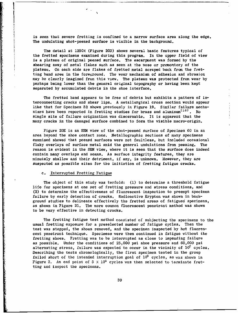
The object of this study was twofold: (1) to determine a threshold fatiguelife for specimens at one set of fretting pressure and stress conditions, and(2) to determine the effectiveness of fluorescent inspection to preempt specimenfailure by early detection of cracks. Radioactive Krypton was shown in back-ground studies to delineate effectively the fretted areas of fatigued specimens,as shown in Figure 21. The more common fluorescent penetrant method was shownto be very effective in detecting cracks.
The fretting fatigue test method consisted of subjecting the specimens to theusual fretting exposure for a preselected number of fatigue cycles. Then thetest was stopped, the shoes removed, and the specimen inspected by hot fluores-cent penetrant technique. Specimens were then continued in fatigue without thefretting shoes. Fretting was to be interrupted as close to impending failureas possible. Under the conditions of 25,000 psi shoe pressure and 60,000 psialternating stress, failure was expected to occur in the vicinity of 105 cycles.Describing the tests chronologically, the first specimen tested in the groupfailed short of the intended interruption goal of 105 cycles, as was shown inFigure 2. An end point of 5 X 10⁴ cycles was then selected to terminate fret-ting and inspect the specimens.
39
(
Approximate Location of Fretted
Band in Specimen.
Figure 21. Autoradiograph Exposures of Kryptonized Fretted Specimens.The Fretted Bands were Effectively Outlined by the Method,but Crack Detection was Difficult. (Industrial Nucleonics)
40
The next test was interrupted at 5 X 10 4 cycles, and fatigue testing con-tinued to failure without the fretting shoes. This specimen was not removedfrom the fixture (no axial load cycle) nor was it given the penetrant inspec-tion, to be certain that such operations did not affect the remaining fatiguelife. The specimen failed after an additional 6000 fatigue cycles in theabsence of continued fretting.
The next specimen was removed from-the fixture after 5 X 100 frettingfatigue cycles and processed through a hot penetrant inspection. The treatmentincluded first a mild etching in dilute HNQ3 -HF and then immersion while heatedto 1800 F into the penetra,-t solution. Fluorescent inspection distinctly re-vealed the fretting pattern along the edges of shoe contact on tho top andbottom surfaces, as illustrated by the "black light" photograph in Figure 22.In addition, cracks were in evidence along the center one-third of each of thefour fretting lines. (These'cracks were also clearly visible at lOX stero-magnification without the penetrant inspection.) The specimen, returned tofatigue testing without shoes, failed in 16,000 additional cycles. Figure 23illustrates the specimen after failure, photographed under normal lighting,showing the origins to have been present on both'fretted surfaces.
Because the previous specimens were terminally damaged by fretting beforethey had accumulated 5 X 10⁴ cycles, the final specimen of the series was in-terrupted at 1 X 10⁴ cycles. Neither visual nor fluorescent penetrant inspec-tion revealed any cracking, although a slight fretting condition was visiblealong the edges of the shoe-contact areas. This specimen was then tested with-out shoes to a total endurance of 1.27 X 10⁶ cycles. The specimen life wasequal to nonfretted baseline conditions; and, confirming this, it failed out-side the fretting bands.
Figure 24 shows an SEM view of Specimen 61, interrupted from fretting,then fatigued to early failure. Both photographs illustrate fretting fatiguecracks which were enlarged and blunted by the HNOj-HF chemical cleaning priorto penetrant inspection. Figure 24 also shows a metallographic cross sectionof such a crack. Acid pitting of the general surface is also evident in theSEM photographs. The upper Photograph illustrates the f,.etted band at theedge of fracture.
The results of these tests showed that under the conditions where fret-ting failure can be expected there was a narrow threshold between 104 and5 X 104 cycles where irrevocable iretting damage was done. Those specimensfretted for 5 X 10⁴ cycles failed in a few thousand additional fatiguecycles after fretting shoes were removed. Furthermore, under the test condi-tions used the incipient failure was clearly evidenced by cracks, highlightedby fluorescent penetrant, but visible at 10 - 15X unaided by the treatment.Similar tests were reported in(18) for brass having such a short crack propaga-tion time that cracks could not be detected, whereas they were easily seen inan Al alloy.
41
IIN
Figue 2. Fettig Ftige Spcimn 6 Phtogrphe Unei~ ltrvioet ight
Revealing~~~~~~ Floecnoeern nteFetdBnSo the' shLýýContact~~~~~~~~~~~~I Ara.Te k'ie a rtedUdr2,0 S heCntact~~~~ PrssN at2,0IS 1a eso ad6 ()PIA entn
Bendng Sres, InerrptedAftr 5 1OCycls ii~ Isei, io6The ~ ~ ~ ~ ~ ~ ~ ~ ~ ~ ~~~g Rih-ad adi ac iwSow Niht loecnc ors
a onin toCavaheeteSei tn;, nual alei SeFgr"23) (Ng471A7,I.X
42M~t
WearArea
Figure 23. Fretting Fatigue Specimen 61 Tested Under 25,000 PSI Shoe ContactPressure at 20,000 PSI MIean Tension and 60,000 PSI AlternatingBending Stress. Fretting was Interrupted at 5 x lO01 Cycles forFluorescent Penetrant Inspection Shown in Figure 22. Fatigue wasContinued, Without Fretting, to Failure at 6.6 x 10a Cycles.Fracture Originated from Bo'th Surfaces where Cracks were Dis-closed at Inspection.
43
SE 66,65,4'x0
Mon 02 Ag 31 0O
Fiue2. SM n ltlogahcVe o pcmn6
444

The test also revealed that if fretting were interrupted before the thres-hold, no cracks were detected in the fretted bands, nor was the specimen lifeshortened. Relative to this, it has been observed in previous~tests arid, inthis program that "run-out" specimens have not exhibited cracks in metallographicsections of the fretted bands., This'not only i6, further evidence, of a narrowthreshold to failure, but also may indicate a futility in attempts :toward pre-ventive inspection for cracks to forestall problems undgr suspected severe,fretting conditions.
d. Elevated.Temperature Tests
The same test fixture and specimen design used fQr room temperature highcycle fatigue was modified for 4000 F' combined stress testing. Dynamic stress.calibration was performed at 4000 F using theisame procedure used for room tem-perature calibration. A new calibration specimenwas instrumented with high-temperature strain gauges and a stress-versus-amplitude curve developed dt400 0 F.
Figure 25 illustrates theltest fixture fitted with r. heat chamber'that waspurged with preheated airas a heat source. Hoi air was chosen because of the,limited space around the specimen in the fixture and the better temperatureuniformity provided by a dynamic heat source versus radiation heat. This isespecially beneficial when heating the irregulai masses that are encounteredwith the large fretting shoes clamped to the flat fatigue specimens. In.Figure 25, the temperature calibration specimen is visible with thermocouplesattached to the sides of the gauge section along the neutral axis. Temperaturecalibration was performed with four 28-gauge chromel-alumel thermocouples weldedto a dunmy test specimen. Temperature distribution around the test section was± 50 F. The fatigue test specimens were instrumented with two thermocoupleswelded on the neutral bending axis on both sides of thd spedimený !One thermo-couple was for control, the other for continuous recording during test. The,specimen was allowed to stabilize'4t temperature fdr a minimum of 1/2 hourprior to testing.
The results of tests conducted at 4000 F are compiled in Table I.' Frettingfatigue test results at 4000 F are shown iniFigure 26. The spedimens tested-at40 ksi included one run-out and two long-lived results. The two failed speci-mens had corner origins indicating no fretting effect. HoweVer specimenstested at 60 ksi failed in short times and exhibitedifretting-related fatigueorigins.
The results are compared in Figure 27 with General E~ectric Company testresults at 6500 F. The tests at 65C° P at the higher stress levels resultedin the same substantial reduction in fatigue life as occurred at 4000 F andat room temperature. However, thbre wps a significant difference in the effectof temperature in tests at lower stresses., Figure 27 shows that at 6500 Fthere was greater loss of fatigue life due to fretting at the run-out stzesslevel. This effect appeared to be related to m6re severe damage incurred bythe specimens, damage as severe as that occasioned by galling during slidingwear tests to be discussed in Task 2.
45 I
1W 4W
(I _____________________________
Figure 25. View of the Fretting Fatigue Fixture Showing Ithe Assembly for
4 000 F Testing. Hfeated Air from a Tube Pur Pac( is; Blown intothe Chamber (Lower Photograph) wvhich Contain.-, thc Jinst ri'-mented Specimen, Exposed in the Upper Phot ogradph.
16
J0
0
0
4)4C
0b.0 0)0)
4-)i- 0 )0 k IC3:NC 0 0 m01
0d 0
00 N
cd CUOP400
F4 I cd k~
CU d4) Q4 r4 ()
&~4
0 00
0C 00to4l
O-OT ~ ~ ~ ~ ~ ~ .x .l'sa~ u~uaVT~uqT
47C
*r.
4.)
0 c 0 0 L
4-) M H 04-3 0)0 0 W 04)- 000 t týr.0
004 M cq C4 to)
UC C:~'-
00 00
4.)) 00 0 'H 000 UH 0
E440
30 4-00
4J4
0d
00.4.4))
U4)
004
~~04
000
0 00 C11
C-O xisc Isais UTptW8 2UT~Uaq;Iv
48
Figure 28A is a macrophotograph of 4000 F Specimen 75 prepared for SFMviewing. Note the presence of deeply scoured wear pits and of raised, attacheddebris. This gross pitting and adhesive buildup of debris was characteristicof the elevated temperature tests and was more severe at 6500 F. Figures 28Band C are SEM views of Specimen 75, respectively, illustrating areas of galledTi buildup and scoured pits in a portion of the wear band.
Pits corresponding tq specimen lumps, and vice versa were present on thewear shoe surfaces. This is clearly illustrated in Figure 29. There thecenter photograph is a portion of the specimen surface at one end of the shoecontact area. The fracture surface extends along the lower edge of the photo-graph, having originated in that fretted band. The corresr-:nding photographof the gauge section of the fretting shoe has been cut in half and the halvesplaced adjacent to the corresponding fretted band of the specimen as mirrorimages. Surface illumination was from below and slightly left for each view.Study of the surface relief shows the matching patterns of pits and attachedlumps of debris.
Figure 30 illustrates a lump of debris on Specimen 75. Like the roomtemperature tests the debris is largely titanium oxide with bits of unoxidizedmetal. Other investigations have identified the debris as rutile, the tetra-gonal form of TiO2 . The wear mechanism of fretting corrosion which producesoxide debris even at room temperature testing is no doubt favored by higherlocal Jpecimen temperature as evidenced by the greater accumulations noted.
Figure 30 also illustrates the oxidation of a shear crack in Specimen 75.The fretted band adjacent to the fracture lip displays the same oblique shearcracks as at room temperature, but they were extensively oxidized. The fret-ting corrosion pits observed did not exhibit cracks, being located generallyfarther into the shoe contact area where bending fatigue stresses are minimal.
Figure 31 is a SEM photograph of two pits and a detail of the largershowing the scoured metal and some debris. Note that around these pits thereis only slight indication of wear striations. This is evidence that the conver-sion of metal to lower-density oxide creates debris which is more voluminousthan the metal particles which it replaces. Accumulation of this wear productcauses the metal surfaces to separate. Wear then intensifies at the remainingareas of contact forming the observed pits and contributes to locally severesurface damage.
3. TASK 2 - SLIDING WEAR/FATIGUE
a. High Cycle Fatigue Effects from Sliding Wear
Task 2 studies were conducted under a two-step test method with specimensfirst subjected to high pressure sliding wear and then tested in high or lowcycle fatigue. The wear test apparatus was shown previously in Figures !ý and3 and the specimen in Figure 7. As for Task 1, all specimens and shoes were
49
AA
WAA
15B 12X -5
Figure~~~~~~~~~~~~ 28. Spcie 75Tse nFetn aiu a 00F h arpoo
Pater. heSE Vew SowDeais f heGrssWer8eaursIn
Raisd Lmps f Ahere Deris
pa-y' F
A A
No,
151B, 130X, 45o x 45'
igue at 4000 F. The Macrophotograph Shows the Generally Extensive Gallingl~s of the Gross Wear Features. Including Scoured-Out Pits and Adjacent
Page 51
~VIOL
0 ýRN0
-WR4
'4- -
0
4 0C~~~~~~~
r-1N''~t~ -. ~j~~
A ,,
Figure 29. Port ion of Sp'c imen from Fretting Fat igue 'Tests at 650" F11 Iust i'a Iiingy a Speclimen a nd(3) SpitI View of Mlated Shoe. Ea chIHalf I of Shoo Photograph is Positioned Adjacent to the WearA rea (4) Show thle Mirror Image of P'itIs aInd Debris Lumps.(Met cut 4-50304l. I 8x)
53 Preceding page blank
jWI
",. ,,.' "' , '*."1/- " " • •,• " " "
., - 3 , -: "~ ,, '.. .,I
Mount 6903, Neg 6301
Figr 30 Cof A-
Debri in Are of Faiu rcueOii.i
.•. • , .,.4
M3ount 6903, Neg 6304
54-Figure 30. Cross Sections of Specimen 75 After 4000 F
F'et ting Fatigue Showing Fretting OxideDebris in Area of Fatigue Fracture Origin.Lower Photograph Illustrates a Lump ofFretting Oxide Debris Such as Shown in thieMacrophotographls in Figures 28 and 29.(thNO 3 .-Hf etchagt, 1000X)
54
SEM1 151C-1, 135X, 200 35'
~ ~ At
'Ile '
SE 11C2,67X,20 x35Figur 31 Spcmn3 hwnqWa iadDti
554
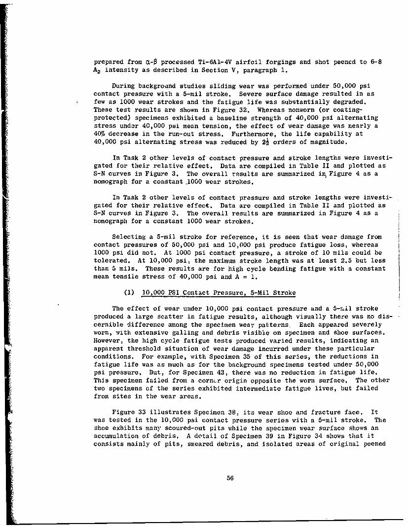
prepared from a-0 processed Ti-6A1-4V airfoil forgings and shot peened to 6-8A2 intensity as described in Section V, paragraph 1.
During backgroand studies sliding wear was performed under 50,000 psicontact pressure with a 5-mil stroke. Severe surface damage resulted in asfew as 1000 wear strokes and the fatigue life was substantially degraded.These test results are shown in Figure 32. Whereas nonworn (or coating-protected) specimens exhibited a baseline strength of 40,000 psi alternatingstress under 40,000 psi mean tension, the effect of wear damage was nearly a40% decrease in the run-out stress. Furthermore, the life capability at40,000 psi alternating stress was reduced by 2j orders of magnitude.
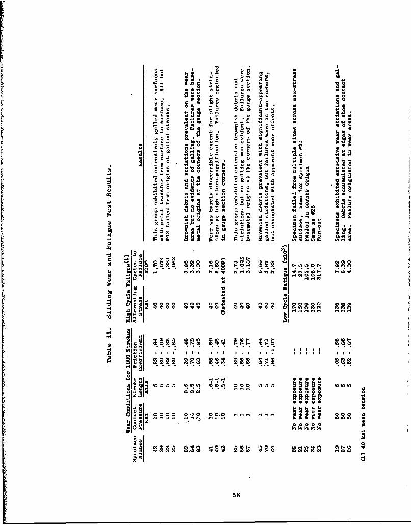
In Task 2 other levels of contact pressure and stroke lengths were investi-gated for their relative effect. Data are compiled in Table II and plotted asS-N curves in Figure 3. The overall results are summarized in Figure 4 as anomograph for a constant .1000 wear strokes.
In Task 2 other levels of contact pressure and stroke lengths were investi-gated for their relative effect. Data are compiled in Table II and plotted asS-N curves in Figure 3. The overall results are summarized in Figure 4 as anomograph for a constant 1000 wear strokes.
Selecting a 5-mil stroke for reference, it is seen that wear damage fromcontact pressures of 50,000 psi and 10,000 psi produce fatigue loss, whereas1000 psi did not. At 1000 psi contact pressure, a stroke of 10 mils could betolerated. At 10,000 psi, the maximum stroke length was at least 2.5 but lessthan 5 mils. These results are for high cycle bending fatigue with a constantmean tensile stress of 40,000 psi and A = 1.
(1) 10,000 PSI Contact Pressure, 5-Mil Stroke
The effect of wear under 10,000 psi contact pressure and a 5-mil strokeproduced a large scatter in fatigue results, although visually there was no dis-cernible difference among the specimen wear patterns. Each appeared severelyworn, with extensive galling and debris visible on specimen and shoe surfaces.However, the high cycle fatigue tests produced varied results, indicating anapparent threshold situation of wear damage incurred under these particularconditions. For example, with Specimen 35 of this series, the reductions infatigue life was as much as for the background specimens tested under 50,000psi pressure. But, for Specimen 43, there was no reduction in fatigue life.This specimen failed from a corncr origin opposite the worn surface. The othertwo specimens of the series exhibited intermediate fatigue lives, but failedfrom sites in the wear areas.
4 Figure 33 illustrates Specimen 38, its wear shoe and fracture face. Itwas tested in the 10,000 psi contact pressure series with a 5-mil stroke. Theshoe exhibits many scoured-out pits while the specimen wear surface shows anaccumulation of debris. A detail of Specimen 39 in Figure 34 shows that itconsists mainly of pits, smeared debris, and isolated areas of original peened
56
'4.)
0k0, Q
0
$4-$4)
4-1 4
00
Cd u
'4-1
k 0
000 .4-)
'4-II
*v4w bxo>00
r14
U) 4.1
4.)40 ) M (0to2 ) 1
r. H 4- l0 co -H N
0) 0 4
= ý0~ 4). 0
0 4- 44~
U) 0
00
(0 C) H)Q 0$ PE
00 $
bD0(*rb
00 0 0
004 (D wN
C-01X I~ 'ssa4S2uT~9S ST~vu.41
(.20 57
021 42 402 t20(a0 140 13 140 b. 02 m b
0.0 020 ;A0 24J -A0 N E4(4.4.4 p.002 k. a r 0 :402) 4-3V
1440 4J b 0200 020 0) 0202 c02 224 (A2)4 020 02) 4 43 04
A2 304 4- 0 02) 0. Z244)02 4002 ed-4 02 00
;40 02 02 (A2 .040 Isr 0r. 0 to .4)4 .02H202 1302 * 0 4)02
to04 m2 02 43) 0020202 0 r4 .0MrA+ 4 ý 02 a)2 a4 $402C
.40204 .44 - Nh .4 4J4 44 "4 02 + %43(4ca20 0 ?A >-N02 a40 k2. .4.4 U 0
4b 024020v144 ( V~02 06 t 020 A00 02 02 m4 ca q b t
r- i 4 002A .4 V00H02 r.. 0 20 X K4J 02 0) .0 0k w2
4be.40 02. m 20 )420 " 4; 4 02f 02ý 4.4 .4)4 0.40 M U , 0 9: 9:4 0430
4) 4) 'NO 0 .aa J b 4)C 4 4.) 0002 42020 .4 *220 0.M k2.
W 0.42" 4)a 4ý 3 4) : a4214. 0 0 92t0200 02 0 H 2 4.04 4 .
43 2) 0 24 .4) 4a $3 r- 4 *4 m4 4 .0 0 3.4(440 020 02 2 . 0 2o.2 4 ( 4 4 0) 4
0 .02 43 10 .002 4 2J 'e4 '10.4020 002020 .40 12 V 2 0
$4) 140 k430 2020 .4 k00V234 . 4) -A 0) .004 g .0 40
.0.4 W02 .002 00 4.) 444 A .5v4 0202 to .4 022. 4.0 M 02-
4) 4.)0 .40 9: t W43 . 4' 2 Cc~0 0 0 2
0z 00M as 4r 04 0 0.4c t b u )Nr
C-4 14 r4c . o'
0 -M A 00 00. -M 4.4 WW4 t'u4,)t 1 A 0
t-us a N O c44C C00c bb .
04 0 4 1 a0 4 4 r02 024$ 0- J1 1 10C
.4 02e.
* 024J4
E4[,04 )00' H.'. go~. 1t.-C- (0 00r41 040 -M OD4
V4 kg
0.
P4 4
o : E32I FA 00 00 0 0 00k42.~ W....4 v V 0+ 0 ) f o c o 0 00
43 014 t:2 20 0 o)02DO v r D t) ot
0434 o3
C)20. 000 0 M'0 00. go 4. .4. 0202020202t000 to
k204) 0000 000 o Mt o 1 vm wWf 2(
00
1+4201 0.010 r-4 r.4 1(1 0'I0 020 00U) 4)
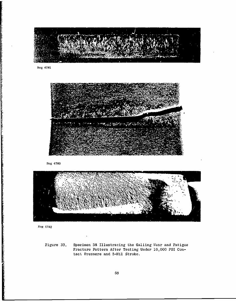
Neg 4781
Neg 4780
~ ~ *INA
Neg 4782
Figure 33. Specimen 38 Illustrating the Galling Wear and FatigueFracture Pattern After Testing Under 10,000 PSI Con-tact Pressure and 5-Mil Stroke.
59
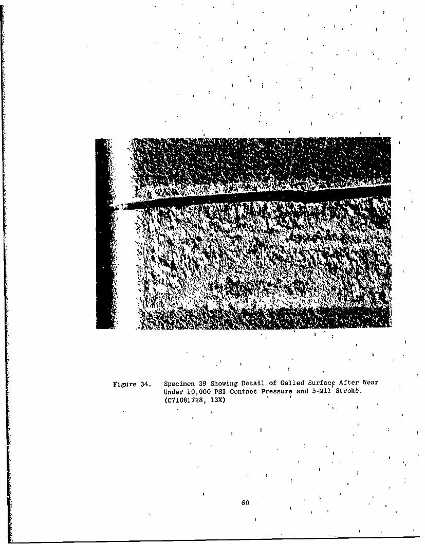
Figure 34. Specimen 39 Showing Detail of Galled Surf acp After WearUnder 10,000 PSI Contact Pressure and 5-Mul Strokb.(M7081728, 13X)
60
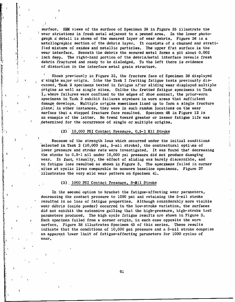
surface. SEM views of the surface of Specimen 38 in Figure 35 illustrate thewear striations in fresh metal adjacent to a peened area. In the lower photo-graph d detail is shown of the smeared layer of wear debris. Figure 36 is ametallographic section of the debris layer. It consists of a churned and strati-fied mixture of oxides and metallic particles. The upper flat surface is thewear interface. Beneath the debris the scoured metal forms a pit about 0.002inch deep. The right-hand portion of the debris/metal interface reveals freshdebris fractured and ready to be dislodged. To the left there is evidenceof distortion in the interface metal grain structure.
SShowh previously in Figure 33, the fracture face of Specimen 38 displayed
a' single major origin. Like the Task I fretting fatigue tests previously dis-cussed, Task 2 specimens tested in fatigue after sliding wear displayed multipledrigins as well as single sites. Unlike the fretted fatigue specimens in Task
I,1where failures were confined to the edges of shoe contact, the prior-wornspecimens in Task 2 exhibit failures anywhere in worn areas that sufficientdamage develops. Multiple origins sometimes lined up to form a single fractureplane; in other instances, they were in such random locations on the wearsurface that a stepped fracture face resulted. Specimen 48 in Figure 12 isan example of the latter. No trend toward greater or lesser fatigue life wasdetermined for the occurrence of single or multiple origins.
(2) 10,000 PSI Contact Pressure, 0.5-1 Mil Stroke
Because of the strength loss which occurred under the initial conditionsselected in Task 2 (10,000 psi, 5-mil stroke), the contractural optiins oflower pressure and stroke rate were investigated. It was found thal decreasing
the stroke to 0.5-1 mil under 10,000 psi pressure did not produce damagingwear. In fact, visually, the effect of sliding was barely discernible, andno fatigue loss resulted as shown in Figure 3. The specimens failed in cornersites at cyclic lives comparable to nonworn baseline specimens. Figure 37illustrates the very mild wear pattern on Specimen 41.
(3) 1000 PSI Contact Pressure, 5-Mil Stroke
In the second option to bracket the fatigue-affecting wear parameters,decreasing the contact pressure to 1000 psi and retaining the 5-mil strokeresulted in no loss of fatigue properties. Although considerably more visiblewear debris (oxide powder) occurred in the low-stroke variation, the surfacesdid not exhibit the extensive galling that the high-pressure, high-stroke testparameters produced. The high cycle fatigue results are shown in Figure 3.Each specimen failed from a corner origin, in each case opposite the wornsurface. Figure 38 illustrates Specimen 45 of this series. These resultsindicate that the conditions of 10,000 psi pressure and a 5-mil stroke comprisean apparent lower limit of fatigue-affecting parameters for 1000 cycles ofwear.
61
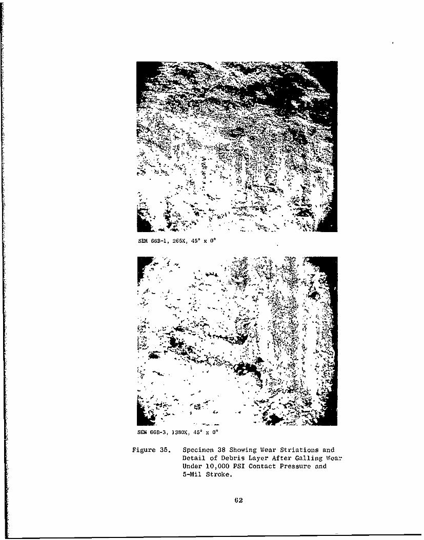
:;t
SEM 66B-1, 265X, 450 x 00
~t
Arr
.~ 45
* ~ ; ' ~.n
itf A~k-tM
SEJA 66B-3, 1380X, 450 x00)
Figure 35. Specimen 38 Showing Wear Striations andDetail of Debris Layer After Galling Wear.Under 10,000 PSI Contact Pressure and5-Mil Stroke.
02
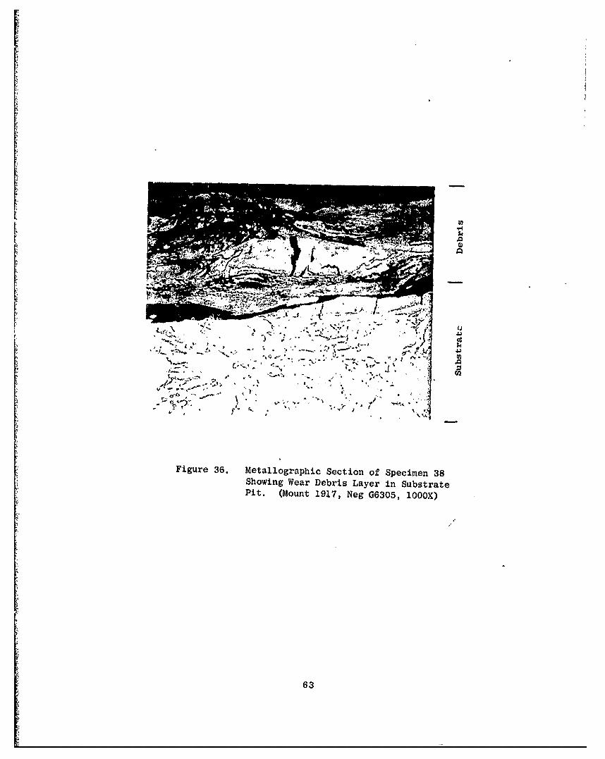
Figure 36. Metallographic Section of Specimen 38Showing Wear Debris Layer in SubstratePit. (Mount 1917, Neg G6305, 1000X)
63
Shioe 11i 1774
~ ;~; ~Wealrlr~ A k
v'P.:. (M C -
'VA "I t*09ý I
fk, N'lpi
v1"N/
41f i
, -:
In T4j 'k- #I~j I :'
Figure :37. Spciuu 1 llu- 1tit ~i tilg, Very Mijld weati Patt Iern on Shoe andSpecimen Aito iL Veav r Tet Under 10,000 PSil Cont~act Pressurean~d 0. 3- 14) 1 -Mii St roy, . (Me tcu I., 6X)
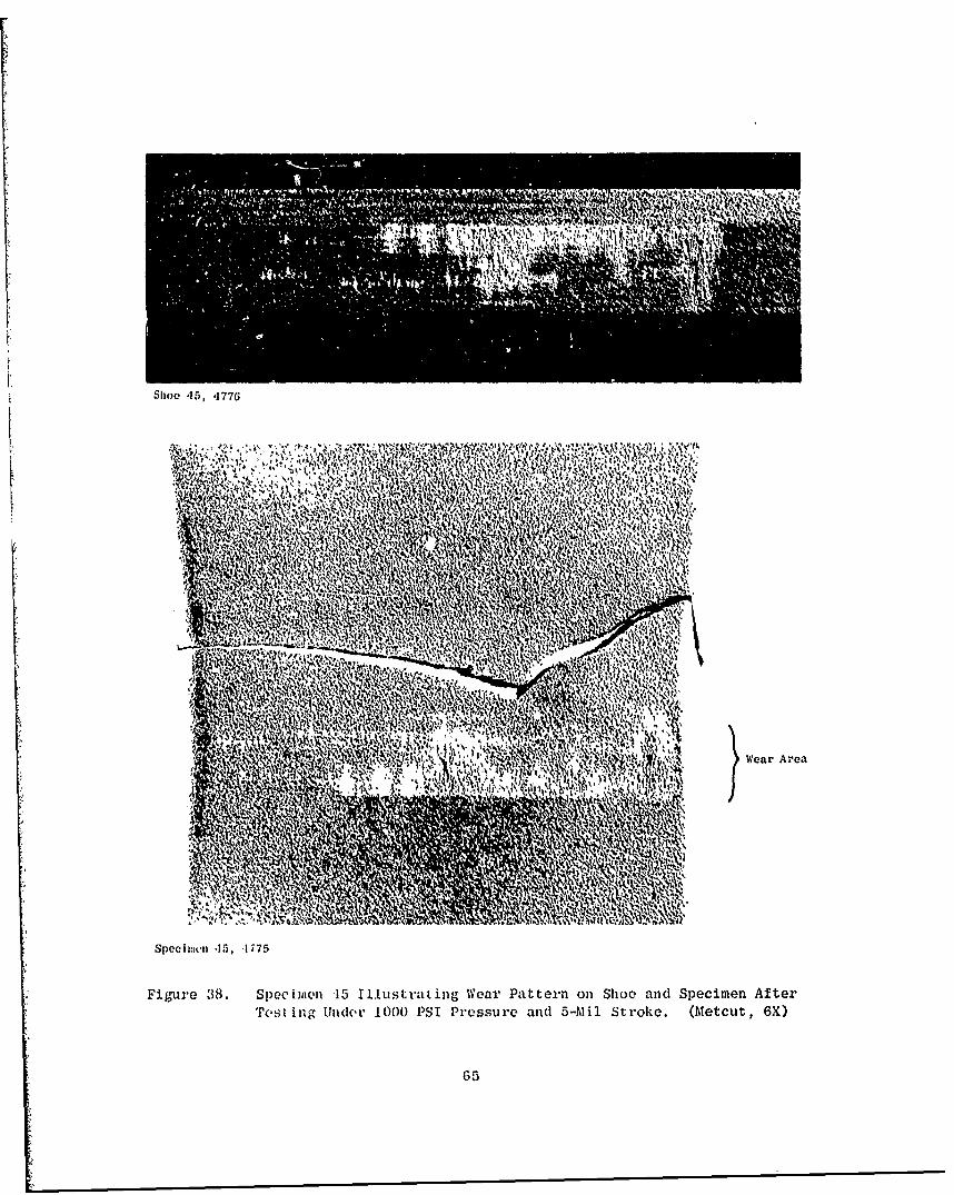
Sh100 45, '1776
.pv.
Oil~~ Wea Area:r o
Spoci~~vI~ 1, 177
Figure~~~~~~~~~" R3. pciiIN 1 lutat erPter nSo n Seie fe
Ml es'A LnMRA'lO)PI rsuead5M trk. (~ect X
MM5
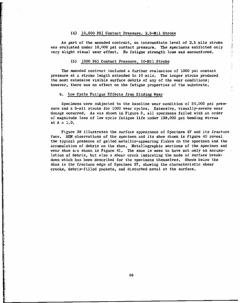
(4) 10 000 PSI Contact Pressure, 2.5-Mil Stroke
As part of the amended contract, an intermediate level of 2.5 mils strokewas evaluated under 10,000 psi contact pressure. The specimens exhibited onlyvery slight visual wear effect. No fatigue strength loss was encountered.
(5) 1000 PSI Contact Pressure, 10-Mil Stroke
The amended contract included a further evaluation of 1000 psi contactpressure at a stroke length extended to 10 mils. The longer stroke producedthe most extensive visible surface debris of any of the wear conditions;however, there was no effect on the fatigue properties of the substrate.
b. Low Cycle Fatigue Effects from Sliding Wear
Specimens were subjected to the baseline wear condition of 50,000 psi pres-sure and a 5-mil stroke for 1000 wear cycles. Extensive, visually-severe weardamage occurred. As was shown in Figure 5, all specimens failed with an orderof magnitude loss of low cycle fatigue life under 138,000 psi bending stressat A = 1.0.
Figure 39 illustrates the surface appearance of Specimen 27 and its fractureface. SEM observations of the specimen and its shoe shown in Figure 40 revealthe typical presence of galled metallic-appearing flakes on the specimen and theaccumulation of debris on the shoe. Metallographic sections of the specimen andwear shoe ae shown in Figure 41. The shoe is seen to have not only an accumu-lation of debris, but also a shear crack indicating the mode of surface break-down which has been described for the specimens themselves. Shown below theshoe is the fracture edge of Specimen 27, showing the characteristic shearcracks, debris-filled pockets, and disturbed metal at the surface.
66
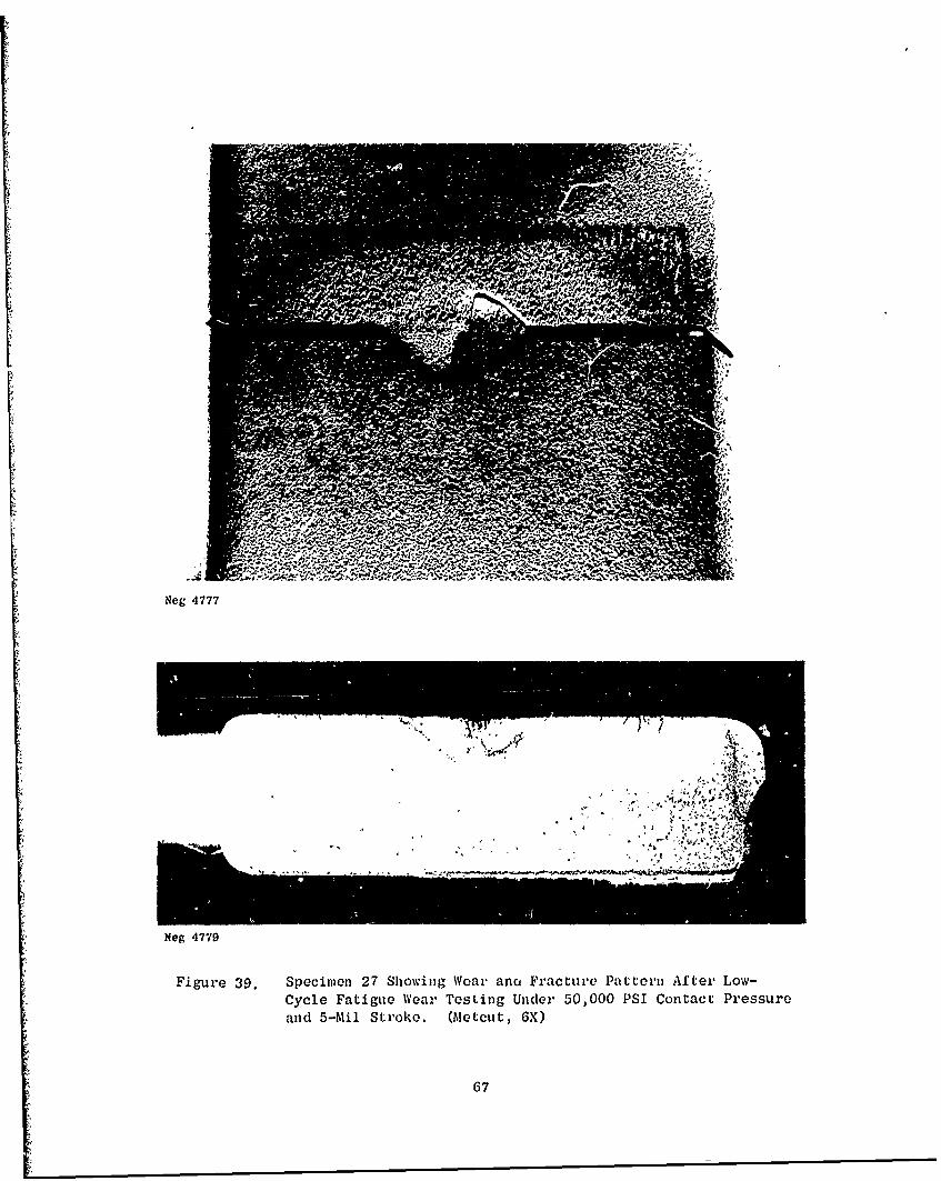
Neg 4777
Neg 4779
Figure 39. Specimen 27 Showing Wear anct Fracture Pattern After Low-Cycle Fatigue Weal' Testing Under 50,000 PSI Contact Pressureand 5-Mil Stroke. (Aletcut, GX)
67
v A.AA
~' ~ %
AA 'Q4
SEM 66A, 590X, 45' o*0
y
f I V
SEM 356F, 9J0\ IS -1* 0'
Figure 40. Specimen 27 Showing Wear D~ebris of Shoe(Upper Photograph) and Galled Mletal Flakeson Specimen (Lower' Photograph) After Test-ing Under 50,000 PSI Contact Pressure and5-Mul Stroke.
68
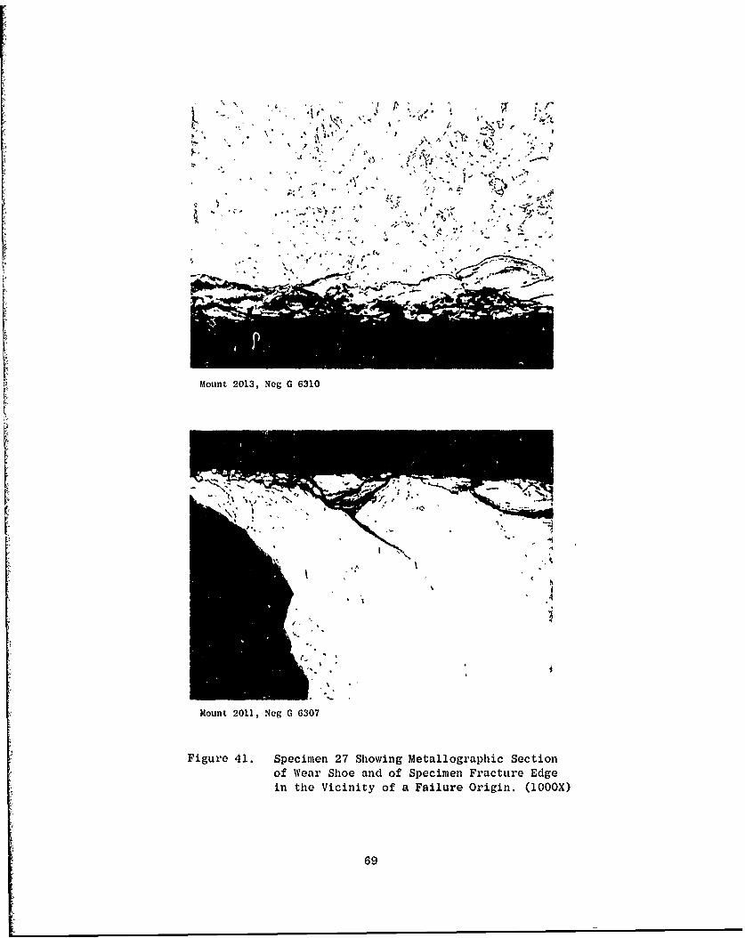
Mon 2013 Ne G 6310 *
Mount2011 Neg 630
Figur 41 pcmn2£hwn Mtlorp eto
of WerSo n fSeie rcueEg
in th iiiyo alr rgn 10X
69
I
SEC TION VI
REFERENCES
1. B.L. Koff, Titanium Fatigue Investigation, GE Technical Report, R67FPD252(1967).
2. R.K. Betts, W.P. Koster and W.J. Stross, Fretting Fatigue of ForgedTi-6A1-4V Related to J-79 Compressor Disc Application, G.E. TechnicalReport No. TM67-773, (1967).
3. R.K. Betts, W.L. Starkey, R.T. Hagon, Final Report - Investigation ofFretting - Fatigue Damage of Titanium Alloy Ti-6A1-4V in Fretting Contactwith 4340 Steel and Ti-6A1-4V Collars, General Electric Company, TM68-388,June, 1968.
4. R.K. Betts, W.P. Koster, W.J. Stross, Fretting Fatigue of Forged Inconel718 Relative to J-97 Compressor Disc Application, General Electric CompanyTM68-404, June, 1968.
5. R.K. Betts, AEG Wear Programs, Status Report No. 1, General Electric Com-pany, TM68-319, May, 1968.
6. V.J. Erdeman, R.D. Radcliffe, Effects of Shot Peening on the Cyclic Lifeof Thermally Exposed and Non-Exposed Ti-6A1-4V and Ti-6A1-2Sn-4Zr-2Mo,General Electric Company, R69AEG166, April, 1969.
7. R.K. Betts, High Cycle Fatigue Effect of Sliding Wear and Prevention byCuNiIn/MoS2 Coating on Ti-6AI-4V, General Electric Company, TM70-82,March, 1970,
8. R.K. Betts, Titanium Dovetail Wear Coatings - Wear/Fatigue Comparison ofCuNiIn, CuNi and NiAl, also MoS 9 and Graphite Lubrication, General ElectricCompany, TM70-633, August, 1970.
9. E. Rabinowicz, Friction and Wear of Materials, Wiley & Sons, (1965).
10. F.P. Bowden and D. Tabor, The Friction and Lubrication of Solids, Part II,Oxford Press (1964).
11. R.A. Wood, Surfact Treatment of Titanium, DMIC Technical Note, BattelleMemorial Institute, March, 1965.
12. N.J. Finch, J.E. Bowers, Surface Treatment of Titanium Alloys: A Rev Awof Published Information, British Non-Ferrous Metals Research Assocfation,Report No. A 1536 (DDC AD439954) May, 1965,
71 Preceding page blank
REFERENCES (concluded)
13. M.W. Mallett, Surface Treatments for Titanium Alloys, NASA TechnicalMemorandum X-53429, October, 1965,
14. R.C. Bowers and C.M. Murphy, Status of Research on Lubricants, Friction,and Wear, Naval Research Laboratory, NRL Report 6466 (1967).
15. R.K. Betts, Effect of Edge Radius and WC-Co Coating on the High CycleBending Fatigue Strength of Ti-6A1-4V Relative to Blade Interlock Geometry,General Electric Company, TY71-214, May, 1971.,
16. R.K. Betts, Low Cycle Fatigue Effects of Wear, General Electric Company,TM71-215, August, 1971.
17. R.K. Betts, Dovetail Wear Coating Evaluation, General Electric Company,TM71-216, April, 1971.
18. R.B. Waterhouse, The Effect of Clamping Stress Distribution on theFretting Fatigue of Alpha Brass and Al-Mg-Zn Alloy, American Society ofLubrication Engineers Transactions 11, 1-5, 1968.
19. M. Cocks, Interaction of Sliding Metal Surfaces, Journal of Applied Physics,Volume 33, No. 7, July 1962.
20. Eugene F. Finkin, What Happens When Parts Wear, Machine Design, March 19,1970.
72