frequency inverters 8200 9300-vector catalog lenze en
TRANSCRIPT

Global DriveFrequency inverters8200/9300 vector 0.37 … 90 kW
490 826 Lenze
Lenze Drive Systems GmbH, Postfach 1013 52, D-31763 HamelnSite: Hans-Lenze-Straße 1, D-31855 Aerzen, Tel. ++49 (0) 5154 82-0, Fax ++49 (0) 5154 82-21 11 E-mail: [email protected] · Internet: http://www.Lenze.comSubject to technical modifications · Printed in Germany 05/04 by ME / LHM · 02/12 en
Lenze2
This catalog will help you to select and order the AC driveyou need quickly and easily.
It features:• Static frequency inverters for controlling three-phase
AC motors• Accessories for assembling and connecting the inverters• Application examples• Order forms
Product selection and orders
Lenze3
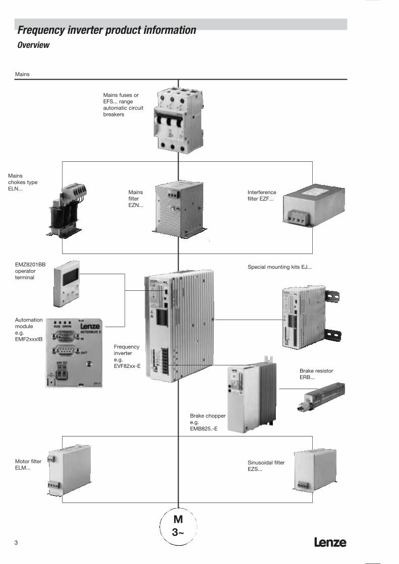
Frequency inverter product informationOverview
M3~
Mains fuses orEFS... rangeautomatic circuitbreakers
Mainschokes typeELN...
Mains
MainsfilterEZN...
Interferencefilter EZF...
Special mounting kits EJ...EMZ8201BBoperatorterminal
Frequencyinvertere.g.EVF82xx-E
Automationmodule e.g.EMF2xxxIB
Brake choppere.g.EMB825.-E
Brake resistorERB...
Motor filterELM...
Sinusoidal filterEZS...

Application intelligence is the feature which sets the GlobalDrive controller apart. When used in machines, it offersdesigners enormous potential for reducing costs.
Starting with the Global Drive 8200 frequency inverters foruse in standard applications or HVAC and pump drives, frequently used additional automation features (e.g. PIDcontroller) have been integrated into the device.
The freely connectable internal control structure of theservo inverters, servo register control, servo cam and 9300 servo position controller eliminates the need for numerousexternal I/O devices. For example, complete positioncontrol has been integrated into the 9300 servo positioncontroller via the software. Each device type providestechnology functions which are able, for example, toexecute subprocesses. The additional switching elementsin the system can be evaluated via the control inputs andoutputs or via the system bus.
There’s only one name for intelligent drives: Global Drive.
An introduction to Lenze
Intelligent drives in automation

Lenze6
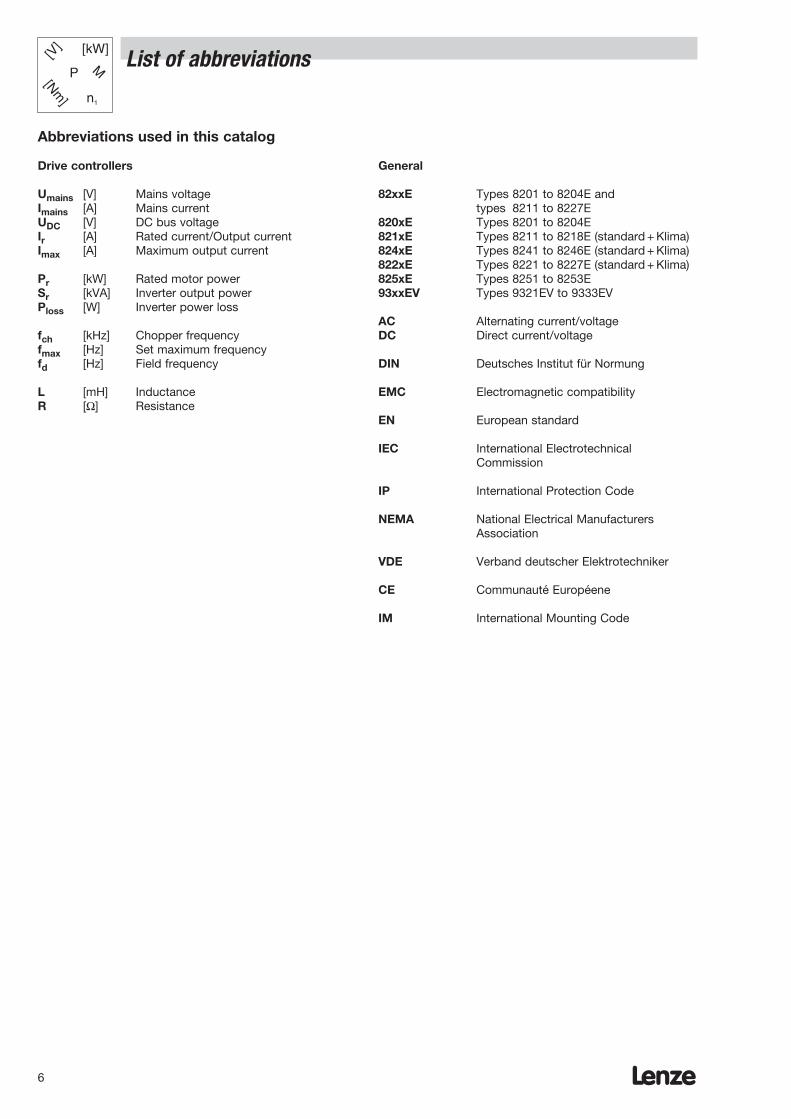
List of abbreviations
Abbreviations used in this catalog
Drive controllers
Umains [V] Mains voltageImains [A] Mains current UDC [V] DC bus voltageIr [A] Rated current/Output currentImax [A] Maximum output current
Pr [kW] Rated motor powerSr [kVA] Inverter output powerPloss [W] Inverter power loss
fch [kHz] Chopper frequencyfmax [Hz] Set maximum frequencyfd [Hz] Field frequency
L [mH] InductanceR [Ω] Resistance
General
82xxE Types 8201 to 8204E andtypes 8211 to 8227E
820xE Types 8201 to 8204E 821xE Types 8211 to 8218E (standard + Klima)824xE Types 8241 to 8246E (standard + Klima)822xE Types 8221 to 8227E (standard + Klima)825xE Types 8251 to 8253E 93xxEV Types 9321EV to 9333EV
AC Alternating current/voltageDC Direct current/voltage
DIN Deutsches Institut für Normung
EMC Electromagnetic compatibility
EN European standard
IEC International Electrotechnical Commission
IP International Protection Code
NEMA National Electrical Manufacturers Association
VDE Verband deutscher Elektrotechniker
CE Communauté Européene
IM International Mounting Code
Lenze 7
Product information 8200___________________________ 8tProduct information - 9300 vector __________________ 10Design - 8200 and 9300 vector _____________________ 13
Frequency inverters ________________________________________________________ 9
Selecting a drive system __________________________ 14
Overview of the 8200 frequency inverter_____________ 16Overview of the 8200 klima frequency inverter _____ 17
General data _____________________________________ 188200 range ratings______________________________ 198210 range ratings______________________________ 208240 range ratings______________________________ 24 8220 range ratings______________________________ 28
Design - 8200 and 9300 vector Overview of the 9300 vector _____________________32General data____________________________________33Ratings ________________________________________34
Mechanical installation ____________________________ 43 General information _____________________________ 43Assembly with fixing rails ________________________ 44Mounting on DIN rails ___________________________ 47Assembly with thermal separation ________________ 48Flat horizontal assembly _________________________ 50Mounting on a swivel bracket ____________________ 50
Line-side electrical installation _____________________ 51 Line protection _________________________________ 51 CE-typical installation ___________________________ 56Mains chokes __________________________________ 58 Interference suppression to EN 55011 limiting value __class A _______________________________________ 62Interference suppression to EN 55011 limiting value __class B _______________________________________ 62 Mains filter A for 8200 and 9300 vector ___________ 66 Mains filter B for 8200 and 9300 vector ___________ 70Subassembly mains filters limiting value class A and B(15 kW … 90 kW) ________________________________73
Motor-side electrical installation ____________________ 75 Output filters ___________________________________ 75Motor filters____________________________________ 76 Sinusoidal filters ________________________________ 78
Braking__________________________________________ 80 Options________________________________________ 80Brake modules _________________________________ 81 Brake choppers ________________________________ 84Brake resistors _________________________________ 86
Supply and regenerative feedback modules _________ 88 General data ___________________________________ 88Mains filter A __________________________________ 90
Design - 82xx
Ordering data
Product information
Contents
DC fuses _______________________________________ 91DC fuses for DC-bus operation andDC power supply________________________________91
8201BB operating module _________________________ 949371BC operating module _________________________ 95
Plug-in modules for 8200 inverters _________________ 96System bus components for 9300 vector ___________ 98
Additional accessories ___________________________ 100Setpoint potentiometer _________________________ 100 Digital display _________________________________ 101
Communication with a host system________________ 102
Overview of accessories for the 8200 inverter_______ 104Accessories for8201 - 8204 frequency inverters_________________ 105Accessories for8211 - 8218 frequency inverters_________________ 106 Accessories for8241 - 8246 frequency inverters_________________ 108Accessories for8221 - 8227 frequency inverters_________________ 110Accessories forsupply and regenerative feedback modules _______111
Overview of accessories for the 9300 vector _______ 112Accessories for9321 - 9333 frequency inverters_________________ 114
Connecting diagrams _____________________________ 118 8200 range power connection___________________ 1188210/8240/8220 range power connection ________ 119 Connection of control terminalsfor the 8200 and 8210 ranges ___________________ 120Connection of control terminals for the 8240/8220 ranges _______________________________________ 1219300 vector range power connection ____________ 123Connecting diagrams for 9300 vector frequency inverters ____________________________ 124
Applications ____________________________________ 125DC-bus operation _____________________________ 125Pump application______________________________ 127Air conditioning system ________________________ 128 Level control __________________________________ 129Step control __________________________________ 130 Traversing control _____________________________ 131Pilot frequency - Slave _________________________ 132Dancer positioning control ______________________ 133
________________________________________________ 136
________________________________________________ 144
Application examples
Order forms
Lenze worldwide

Lenze8
Product information 8200
A complete programme– Frequency inverters for single-phase and three-
phase mains connection– Line-side and motor-side accessories– Accessories for braking– Accessories for networking with host system– Device variants for special applications
User-friendlinessAn attachable operating module with an LCDdisplay makes it easy to set parameters for and configure your drive system. The operating modulealso displays the status of the drive and is used for troubleshooting as well as for transferring parametersto other devices.
Ready for immediate operationThe frequency inverters are preset for standardoperation, e.g. with Lenze geared motors. The preset parameters include:– Maximum torque at low frequencies– Safe start with maximum load– Controlled acceleration and deceleration due to
current limiting control– Assignment of standard functions to inputs
and outputs
Communication optionsThe frequency inverters communicate with a higher-level host system via attachable communication modules:
– LECOM-AB: Networking via the RS232/485interface
– LECOM-LI: Networking via optical fibres
– INTERBUS-S: Remote bus link withDRIVECOM profile 21
– System bus Link to I/O terminals,(CAN): as well as links between
a number of inverters– PROFIBUS: Serial coupling to
PROFIBUS-DP
HVAC versionThe following features are amongst those required inHVAC and pump drive applications:
– PID controller– Manual-remote changeover– Belt monitoring
The 8200 HVAC and pump drive inverter meets theserequirements.
CE conformityThe 8200 range frequency inverters meet the requirements of the following EU guidelines:– CE conformance according to the Low-Voltage
Directive– CE conformance with the EU’s EMC directive for
generic drive configurations with frequency inverters
Overload capacityFlux Torque Control (FTC) can make available up to180% rated torque. This significantly increases thedrive’s torque and dynamics.
Operational reliabilityAn adjustable slip compensation functioncompensates load-dependent speed deviations without complex speed feedback. The maximumcurrent limitation ensures stable operation at all times with static and dynamic loads.
AdaptabilityThe selectable form of the V/f characteristic enables the frequency inverter to be adapted to loads with constant or square-law torque. The integrated flying restart circuit enables the machine to be restarted even if the shaft is still rotating.
Optimised performanceThe performance of the devices can be optimised byapplying 150% or 120% overload:– 150% overload for example for transportation
systems, packaging machines, etc.– 120% overload for example for pumps,
air conditioning systems, etc.
i
Lenze 9
Product information 8200
VersatilityMany different types of three-phase AC motors can be controlled:– Three-phase asynchronous motors– Three-phase reluctance motors– Motors for use in hazardous areas
(pressure-enclosed)– Medium-frequency motors up to max. 480 Hz
The correct setpoint source for every application:– Via setpoint potentiometer on the control
terminals– Via master reference voltage or master reference
current on the control terminals– Via the operating module on the frequency
inverter– Via a networking module directly from a
host system
Energy-savingThe power is adapted to the drive requirements, i.e. the momentary torque and current requirements.
Space in the control cabinetThe frequency inverters are particularly compactas they can be mounted directly side by side,without the need for any clearance in between. Thanks to an extensive range of fixing accessories, they can be used in a variety of mounting positions.
Ease of controller connectionThe plug-in terminal system means that all control connections can be accessed easily from outside the unit.
A Lenze geared motor – Your ideal partnerIn terms of technology, Lenze geared motors are perfectly compatible with 8200 frequency inverters. Commissioning could not be easier, as the frequencyinverter is configured for the motor data. There is no need to set motor data parameters.(You can find more information about Lenze geared motors in the corresponding catalog.)
Special applications? No problem.Device variants mean that the ranges can be adapted for use in any application:– Convection-cooled version 4.0 kW upwards
Please contact us should you require more information.
i
Lenze10
Product information - 9300 vector
A complete programme– Frequency inverter for three-phase mains
connection– Line-side and motor-side accessories– Accessories for braking– Accessories for networking with host systems– Device variants for special applications
User-friendlinessAn attachable operating module with an LCDdisplay makes it easy to set parameters for and configure your drive system. The operating modulealso displays the status of the drive and is used fortroubleshooting as well as for transferring parametersto other devices.
Ready for immediate operationThe frequency inverters are preset for standard operation, e.g. with Lenze geared motors. The preset parameters include:– V / f characteristic control with adjusted slip
compensation– Controlled acceleration and deceleration due to
preset current limiting control– Assignment of standard functions to inputs and
outputs
Communication optionsThe frequency inverters communicate with a higher-level host system via attachable communication modules:
– LECOM-AB: Networking via the RS232/485interface
– LECOM-LI: Networking via optical fibres
– INTERBUS-S: Remote bus link with DRIVECOM profile 21
– System bus Link to I/O terminals,(CAN): as well as links between
a number of inverters (integrated)– PROFIBUS: Serial coupling to
PROFIBUS-DP
CE conformity9300 range frequency inverters meet the requirements of the following EU guidelines:– CE conformance with the Low-Voltage Directive– CE conformance with the EU’s EMC directive for
generic drive configurations with frequency inverters
Overload capacityVector Control can make available up to twice therated torque. This significantly increases the drive’s torque anddynamics.
Operational reliabilityConfigurable slip compensation can be employed tocompensate load-dependent fluctuations in speedwithout having to apply complex speed feedback.The maximum current limiting function ensures stable operation at every operating point for bothstatic and dynamic loads.
AdaptabilityThe selectable form of the V/f characteristic enablesthe frequency inverter to be adapted to loads withconstant or square-law torque. The integrated flyingrestart circuit enables the machine to be restartedeven if the shaft is still rotating.
Optimised performanceThe performance of the devices can be optimised byapplying 150% or 120% overload:– 150% overload for example for transportation
systems, packaging machines, etc.– 120% overload for example for pumps,
air conditioning systems, etc.
i
Lenze 11
Product information - 9300 vector
VersatilityMany different types of three-phase AC motors can be controlled:– Three-phase asynchronous motors– Three-phase synchronous motors– Three-phase reluctance motors– Motors for use in hazardous areas
(pressure-enclosed)– Medium-frequency motors up to max. 600 Hz
The correct setpoint source for every application:– Via setpoint potentiometer on the control
current on the control terminals– Via master reference voltage or master reference
current on the control terminals– Via the operating module on the frequency
inverter– Via a networking module directly from a
host system
Energy-savingThe power is adapted to the drive requirements, i.e. the momentary torque and current requirements.
Space in the control cabinetThe frequency inverters are particularly compactas they can be mounted directly side by side,without the need for any clearance in between. Thanks to an extensive range of fixing accessories, they can be used in a variety of mounting positions.
Increased functionality makes control significantly easier:– Pilot frequency for synchronous operation using
simple connectors– Vector Control for maximum dynamics and high
starting torque– Modular, freely configurable control/function
blocks which can be linked incredibly easily– Process controller and arithmetic blocks for
closed-loop and open-loop control tasks– Integrated system bus for linking a number of
controllers
Regenerative feedback modulesFor energy-saving interconnected and multi-axisapplications.
Ease of controller connectionThe plug-in terminal system means that all controlcurrent terminals can be accessed easily from outside the unit.
A Lenze geared motor – Your ideal partnerIn terms of technology, Lenze geared motors are perfectly compatible with 93xx frequency inverters. Commissioning could not be easier, as the frequencyinverter is configured for the motor data. There is no need to set motor data parameters.(You can find more information about Lenze geared motors in the corresponding catalog.)
Please contact us should you require more information.
i
Lenze12
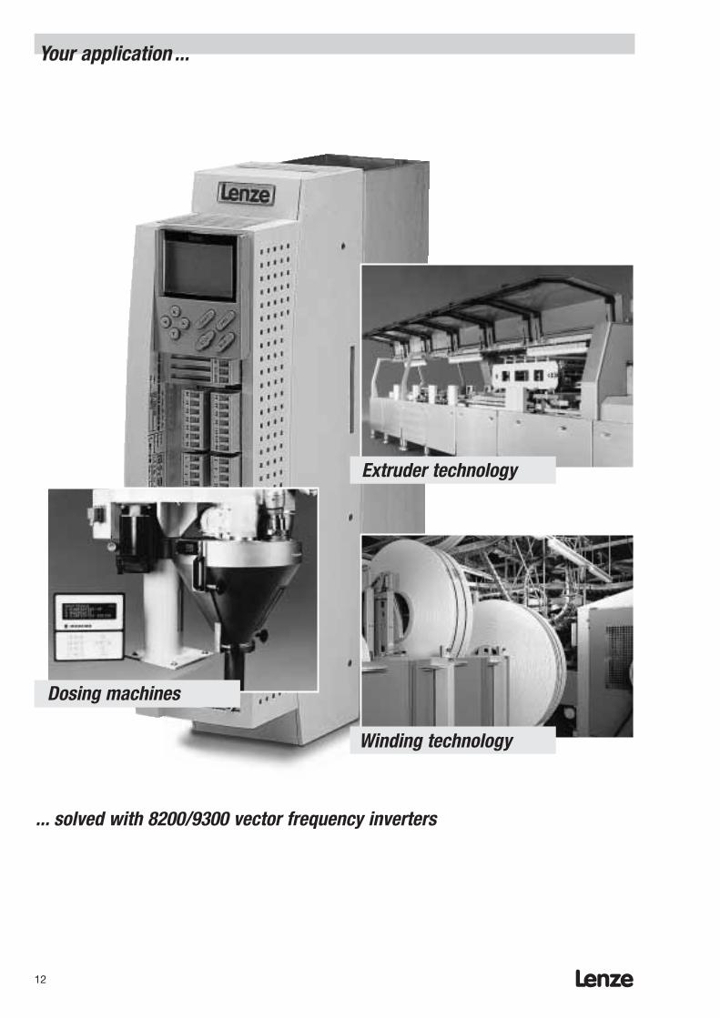
Dosing machines
Winding technology
Extruder technology
Your application ...
... solved with 8200/9300 vector frequency inverters

Lenze 13
Design - 8200 and 9300 vector Inverters for your application
i
Your application Transport and Flow Miniature handling Extruders,conveyor drives drives, equipment, dosing machines,
pumps, beverage and wood processing,air conditioning systems snack warehousing,
dispensers etc.
Task/ Few Industrial Small-scale ComplexApplication technology applications applications
functions
Single-phase 8201-8204 8201-8204 with –0.37 – 2.2 kW Plug-in modules
0.37 – 2.2 kW
Three-phase 8211-8218 8211-8218 V020 8211-8218 9321-93338221-8227 8221-8227 V020 with Vector8241-8246 8241-8246 V020 plug-in modules 0.37 – 110 kW0.37 – 110 kW 0.37 – 110 kW 0.37 – 11 kW
Compact design
Short circuit protected
FTC process
Vector Control
Flying restart circuit
Bipolar setpoint
Motor potentiometer
Freely assignableinputs/outputs
Elapsed timemeter
Fault indication output
DCbraking
Slipcompensation
Skip frequencies
PID controller
Manual/remote
Belt monitoring
4 parameter sets
Mainsmonitoring
Pilot frequency input
Sensorlessrotational speed control
Modularfunction blocks
Integrated system bus
Design - 8200 and 9300 vector Selecting a drive system
Lenze14
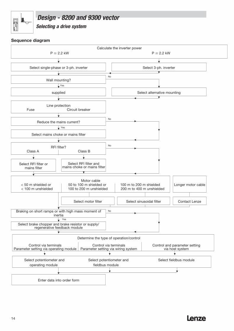
Sequence diagram
Wall mounting?
supplied
RFI filter?Class A Class B
Select RFI filter or mains filter
Motor cable< 50 m shielded or 50 to 100 m shielded or 100 m to 200 m shielded < 100 m unshielded 100 to 200 m unshielded 200 m to 400 m unshielded
Select RFI filter and mains choke or mains filter
Select 3-ph. inverter
Calculate the inverter powerP 2.2 kW P 2.2 kW
Select motor filter Select sinusoidal filter Contact Lenze
Longer motor cable
Braking on short ramps or with high mass moment of inertia
Select brake chopper and brake resistor or supply/regenerative feedback module
Determine the type of operation/control
Control via terminals Control via terminals Control and parameter setting Parameter setting via operating module Parameter setting via wiring system via host system
Select potentiometer and Select potentiometer and Select fieldbus moduleoperating module fieldbus module
Enter data into order form
Select single-phase or 3-ph. inverter
Select alternative mounting
Line protectionFuse Circuit breaker
Reduce the mains current?
Select mains choke or mains filter
No
No
No
No
Yes
Yes
Yes

Lenze 15
The following sections of this catalog will assist you in finding a tailor-made frequency inverter for your machines.Enter your selection in the order form.
Å This section provides extensive information Example:
1. Select the 82XX-E device type • Inverter drive for 7.5 kW motor with 150% (Å Design, Technical data) overload capacitySelect the drive controller to control the speedof the three-phase AC motor. The type of device will EVF8217-Edepend on the motor power required.
2. Select how the device is to be installed • As the heat sink is installed separately, a smaller (Å Design, Mechanical installation) controlcabinet can be used.Select the accessories for installing your frequency inverter. Frame for thermal separation EJ0004
3. Select the line-side accessories • Drive location:(Å Design, Line-side electrical installation) On an industrial networkSelect the appropriate fuses and the accessoriesto ensure conformance with the limiting value classes • Radio interference suppression:specified if the applicable European legislation. The environmental conditions require limiting
value class A to EN 55011
RFI filter EZF3-025A001
4. Select the motor-side accessories • Motor cable:(Å Design, Motor-side electrical installation) Length 210 m, unshieldedSpecial measures may be required for motor cableslonger than 50m: Select your simple and cost-effective solution withcompact motor filters or sinusoidal filters. Sinusoidal filter EZS3-025A
5. Select additional accessories for • For analog setpoint selection via mastercontrolling the device voltage or master current:(Å Design, Additional accessories)Select useful accessories for controlling Setpoint potentiometer ERPD0001k0001Wthe device: Scale for potentiometer ERZ0001- Operating module Rotary button for potentiometer ERZ0002- Automation accessories- Setpoint potentiometer. • If you need a quick and easy device for
changing the factory settings:
Operating module EMZ8201BB
Ordering data - 8200 and 9300 vector
A step-by-step guide to ordering your drive
i
Our example is based on the 82xx-E frequency inverter. Follow the same procedure for the 9300 vector frequency inverter.
Lenze16
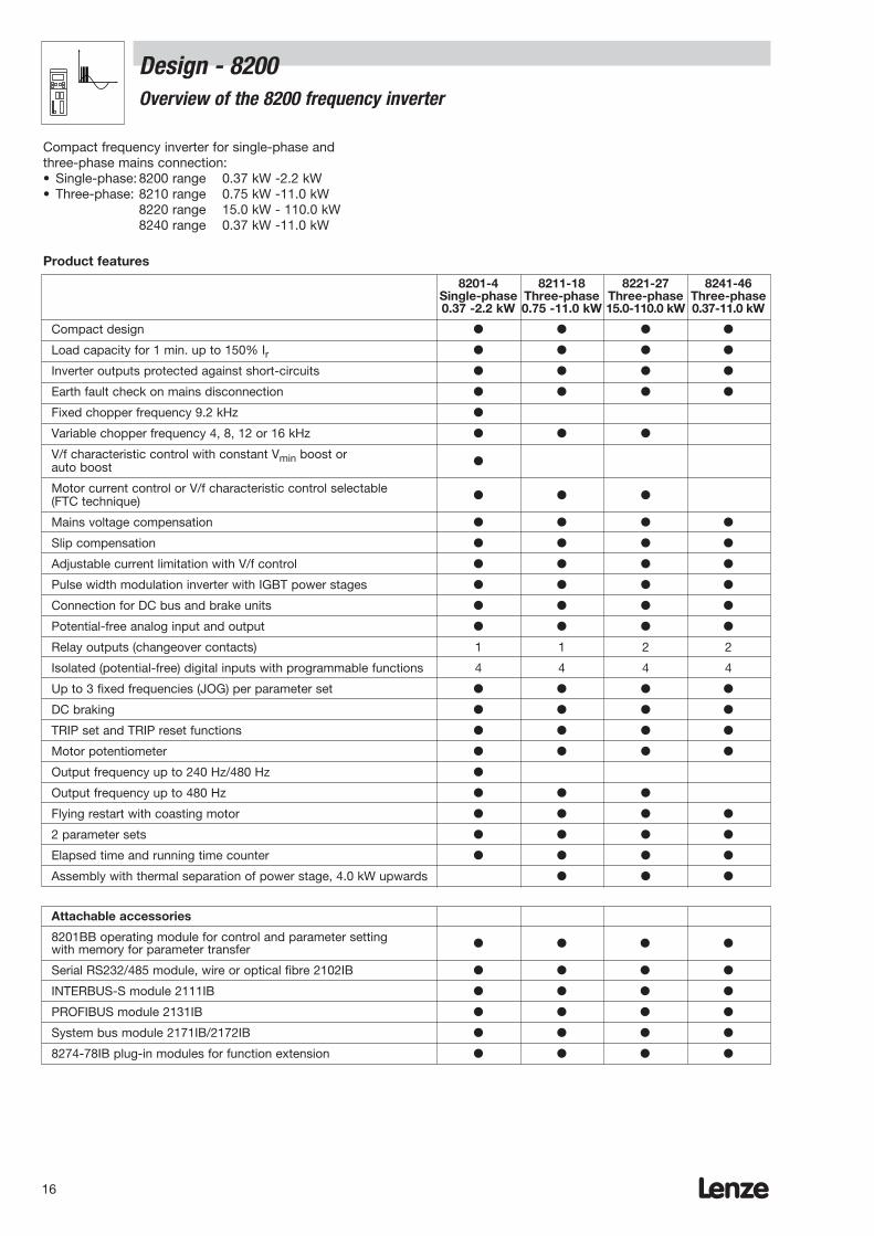
Attachable accessories
8201BB operating module for control and parameter settingwith memory for parameter transfer
Serial RS232/485 module, wire or optical fibre 2102IB
INTERBUS-S module 2111IB
PROFIBUS module 2131IB
System bus module 2171IB/2172IB
8274-78IB plug-in modules for function extension
8201-4 8211-18 8221-27 8241-46Single-phase Three-phase Three-phase Three-phase0.37 -2.2 kW 0.75 -11.0 kW 15.0-110.0 kW 0.37-11.0 kW
Compact design
Load capacity for 1 min. up to 150% Ir
Inverter outputs protected against short-circuits
Earth fault check on mains disconnection
Fixed chopper frequency 9.2 kHz
Variable chopper frequency 4, 8, 12 or 16 kHz
V/f characteristic control with constant Vmin boost or auto boost
Motor current control or V/f characteristic control selectable(FTC technique)
Mains voltage compensation
Slip compensation
Adjustable current limitation with V/f control
Pulse width modulation inverter with IGBT power stages
Connection for DC bus and brake units
Potential-free analog input and output
Relay outputs (changeover contacts) 1 1 2 2
Isolated (potential-free) digital inputs with programmable functions 4 4 4 4
Up to 3 fixed frequencies (JOG) per parameter set
DC braking
TRIP set and TRIP reset functions
Motor potentiometer
Output frequency up to 240 Hz/480 Hz
Output frequency up to 480 Hz
Flying restart with coasting motor
2 parameter sets
Elapsed time and running time counter
Assembly with thermal separation of power stage, 4.0 kW upwards
Design - 8200Overview of the 8200 frequency inverter
Compact frequency inverter for single-phase andthree-phase mains connection:• Single-phase: 8200 range 0.37 kW -2.2 kW• Three-phase: 8210 range 0.75 kW -11.0 kW
8220 range 15.0 kW - 110.0 kW8240 range 0.37 kW -11.0 kW
Product features
Lenze 17
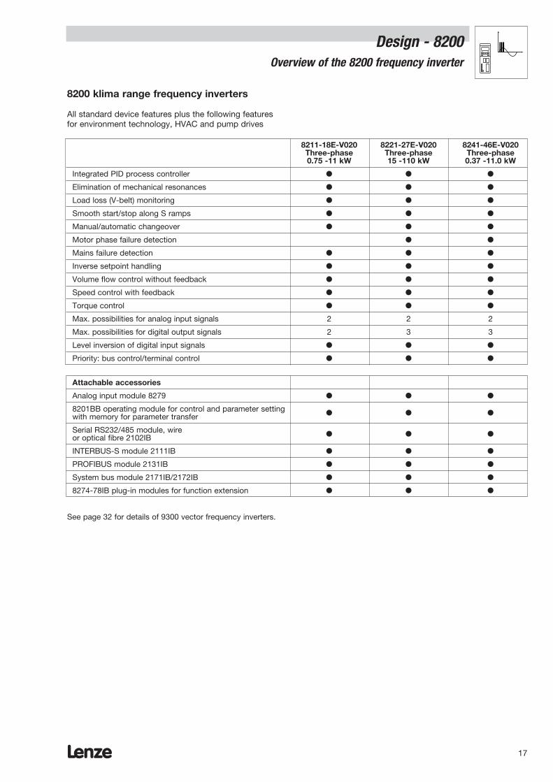
8211-18E-V020 8221-27E-V020 8241-46E-V020Three-phase Three-phase Three-phase0.75 -11 kW 15 -110 kW 0.37 -11.0 kW
Integrated PID process controller
Elimination of mechanical resonances
Load loss (V-belt) monitoring
Smooth start/stop along S ramps
Manual/automatic changeover
Motor phase failure detection
Mains failure detection
Inverse setpoint handling
Volume flow control without feedback
Speed control with feedback
Torque control
Max. possibilities for analog input signals 2 2 2
Max. possibilities for digital output signals 2 3 3
Level inversion of digital input signals
Priority: bus control/terminal control
Design - 8200Overview of the 8200 frequency inverter
8200 klima range frequency inverters
All standard device features plus the following featuresfor environment technology, HVAC and pump drives
Attachable accessories
Analog input module 8279
8201BB operating module for control and parameter settingwith memory for parameter transfer
Serial RS232/485 module, wire or optical fibre 2102IB
INTERBUS-S module 2111IB
PROFIBUS module 2131IB
System bus module 2171IB/2172IB
8274-78IB plug-in modules for function extension
See page 32 for details of 9300 vector frequency inverters.
Lenze18
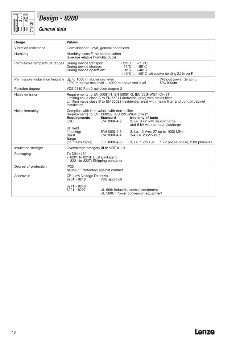
Design - 8200General data
Range Values
Vibration resistance Germanischer Lloyd, general conditions
Humidity Humidity class F, no condensation (average relative humidity 85%)
Permissible temperature ranges During device transport: - 25°C ... +7 0°CDuring device storage: - 25°C ... +55°CDuring device operation: 0°C ... +40°C
+40°C ... +50°C with power derating 2.5% per K
Permissible installation height h Up to 1000 m above sea level Without power derating1000 m above sea level ... 4000 m above sea level 5%/1000m
Pollution degree VDE 0110 Part 2 pollution degree 2
Noise emission Requirements to EN 50081-1, EN 50081-2, IEC 22G-WG4 (Cv) 21Limiting value class A to EN 55011 (industrial area) with mains filterLimiting value class B to EN 55022 (residential area) with mains filter and control cabinetinstallation
Noise immunity Complies with limit values with mains filterRequirements to EN 50082-2, IEC 22G-WG4 (Cv) 21Requirements Standard Intensity of testsESD EN61000-4-2 3, i.e. 8 kV with air discharge
and 6 kV with contact dischargeHF field(housing) EN61000-4-3 3, i.e. 10 V/m; 27 up to 1000 MHzBurst EN61000-4-4 3/4, i.e. 2 kV/5 kHzSurge(on mains cable) IEC 1000-4-5 3, i.e. 1.2/50 µs 1 kV phase-phase, 2 kV phase-PE
Insulation strength Overvoltage category III to VDE 0110
Packaging To DIN 4180- 8201 to 8218: Dust packaging- 8221 to 8227: Shipping container
Degree of protection IP20NEMA 1: Protection against contact
Approvals CE: Low-Voltage Directive8201 - 8218: VDE approval
8241 - 8246,8221 - 8227: UL 508: Industrial control equipment
UL 508C: Power conversion equipment

Type 8201 8202 8203 8204
Order ref. EVF8201-E EVF8202-E EVF8203-E EVF8204-E
Order ref. EVF8202-Ecompact device -V002
Mains voltage UM [V] 1 / N / PE / AC / 230V / 50 Hz / 60 Hzpermissible range 190...260 V ± 0% / 45...65 Hz ± 0%
Alternative DC supply UDC [V] 270 V...360 V ± 0%
Output voltage1) 3 / PE / AC / 0...Umains / 0...50 Hz , up to 240 Hz as an option
Data for operation on mains: 1 AC / 230 V / 50 Hz / 60 Hz
Motor power 4-pole ASM kW 0.37 0.75 1.50 2.20
Output current A 2.6 4.0 7.0 9.5
Max. output current 60 s A 3.9 6.0 10.5 14.2
Output power kVA 1.0 1.5 2.7 3.6
Mains r.m.s. current2)
Without mains choke/filter A 5.0 9.0 15.0 –With mains choke/filter 4.2 7.5 12.5 17.0
Power loss W 30 50 70 100
Chopper frequency Up to 9.2 kHz
Field frequency Resolution 50 mHz absoluteAccuracyDigital setpoint preselection ± 0.05 HzAnalog setpoint preselection- Linearity ± 0.5% max. selected- Temperature sensitivity 0...40°C + 0.4% signal level - Offset ± 0.3% 5 V or 10 V
Dimensionsa mm 64 64 83 83b 180 180 250 250e 158 198 (158) 211 211
Weight kg 1.0 1.3 2.2 2.2Weight (compact device) 1.0
1) With mains choke/filter: Max. output voltage = approx. 96% of mains voltage2) Take the N-conductor load into account if the mains power is being distributed symmetrically on a number of inverters!
Lenze 19
Design - 8200Ratings
Frequency inverter for single-phase mains connection
ae
b
Lenze20
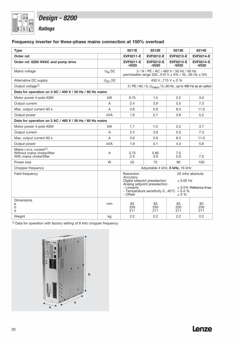
Design - 8200Ratings
Type 8211E 8212E 8213E 8214E
Order ref. EVF8211-E EVF8212-E EVF8213-E EVF8214-E
Order ref. 8200 HVAC and pump drive EVF8211-E EVF8212-E EVF8213-E EVF8214-E-V020 -V020 -V020 -V020
Mains voltage UM [V] 3 / N / PE / AC / 460 V / 50 Hz / 60 Hzpermissible range 320...510 V ± 0% / 45...65 Hz ± 0%
Alternative DC supply UDC [V] 450 V...715 V ± 0 %
Output voltage1) 3 / PE / AC / 0...Umains / 0...50 Hz , up to 480 Hz as an option
Data for operation on 3 AC / 400 V / 50 Hz / 60 Hz mains
Motor power 4-pole ASM kW 0.75 1.5 2.2 3.0
Output current A 2.4 3.9 5.5 7.3
Max. output current 60 s A 3.6 5.9 8.3 11.0
Output power kVA 1.6 2.7 3.8 5.2
Data for operation on 3 AC / 460 V / 50 Hz / 60 Hz mains
Motor power 4-pole ASM kW 1.1 1.5 2.2 3.7
Output current A 2.4 3.9 5.5 7.3
Max. output current 60 s A 3.6 5.9 8.3 11.0
Output power kVA 1.9 3.1 4.3 5.8
Mains r.m.s. current1)
Without mains choke/filter A 3.75 5.85 7.5 -With mains choke/filter 2.5 3.9 5.0 7.0
Power loss W 55 75 90 100
Chopper frequency Adjustable 4 kHz, 8 kHz, 16 kHz
Field frequency Resolution 20 mHz absoluteAccuracyDigital setpoint preselection ± 0.05 HzAnalog setpoint preselection- Linearity ± 0.5% Reference fmax- Temperature sensitivity 0...40°C + 0.4 % - Offset ± 0 %
Dimensionsa mm 83 83 83 83b 250 250 250 250e 211 211 211 211
Weight kg 2.2 2.2 2.2 2.2
1) Data for operation with factory setting of 8 kHz chopper frequency
ae
b
Frequency inverter for three-phase mains connection at 150% overload
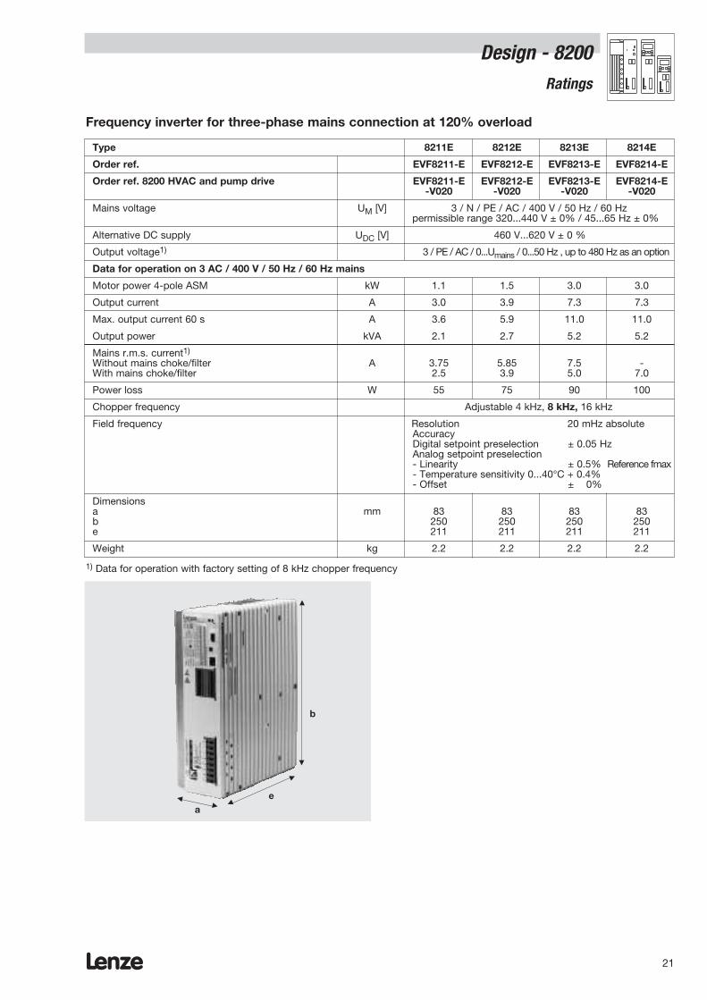
Type 8211E 8212E 8213E 8214E
Order ref. EVF8211-E EVF8212-E EVF8213-E EVF8214-E
Order ref. 8200 HVAC and pump drive EVF8211-E EVF8212-E EVF8213-E EVF8214-E-V020 -V020 -V020 -V020
Mains voltage UM [V] 3 / N / PE / AC / 400 V / 50 Hz / 60 Hzpermissible range 320...440 V ± 0% / 45...65 Hz ± 0%
Alternative DC supply UDC [V] 460 V...620 V ± 0 %
Output voltage1) 3 / PE / AC / 0...Umains / 0...50 Hz , up to 480 Hz as an option
Data for operation on 3 AC / 400 V / 50 Hz / 60 Hz mains
Motor power 4-pole ASM kW 1.1 1.5 3.0 3.0
Output current A 3.0 3.9 7.3 7.3
Max. output current 60 s A 3.6 5.9 11.0 11.0
Output power kVA 2.1 2.7 5.2 5.2
Mains r.m.s. current1)
Without mains choke/filter A 3.75 5.85 7.5 -With mains choke/filter 2.5 3.9 5.0 7.0
Power loss W 55 75 90 100
Chopper frequency Adjustable 4 kHz, 8 kHz, 16 kHz
Field frequency Resolution 20 mHz absoluteAccuracyDigital setpoint preselection ± 0.05 HzAnalog setpoint preselection- Linearity ± 0.5% Reference fmax- Temperature sensitivity 0...40°C + 0.4% - Offset ± 0%
Dimensionsa mm 83 83 83 83b 250 250 250 250e 211 211 211 211
Weight kg 2.2 2.2 2.2 2.2
1) Data for operation with factory setting of 8 kHz chopper frequency
Lenze 21
ae
b
Frequency inverter for three-phase mains connection at 120% overload
Design - 8200Ratings
Lenze22
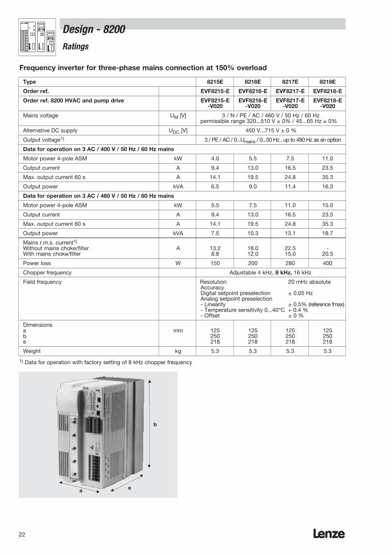
Design - 8200Ratings
Type 8215E 8216E 8217E 8218E
Order ref. EVF8215-E EVF8216-E EVF8217-E EVF8218-E
Order ref. 8200 HVAC and pump drive EVF8215-E EVF8216-E EVF8217-E EVF8218-E-V020 -V020 -V020 -V020
Mains voltage UM [V] 3 / N / PE / AC / 460 V / 50 Hz / 60 Hzpermissible range 320...510 V ± 0% / 45...65 Hz ± 0%
Alternative DC supply UDC [V] 450 V...715 V ± 0 %
Output voltage1) 3 / PE / AC / 0...Umains / 0...50 Hz , up to 480 Hz as an option
Data for operation on 3 AC / 400 V / 50 Hz / 60 Hz mains
Motor power 4-pole ASM kW 4.0 5.5 7.5 11.0
Output current A 9.4 13.0 16.5 23.5
Max. output current 60 s A 14.1 19.5 24.8 35.3
Output power kVA 6.5 9.0 11.4 16.3
Data for operation on 3 AC / 460 V / 50 Hz / 60 Hz mains
Motor power 4-pole ASM kW 5.5 7.5 11.0 15.0
Output current A 9.4 13.0 16.5 23.5
Max. output current 60 s A 14.1 19.5 24.8 35.3
Output power kVA 7.5 10.3 13.1 18.7
Mains r.m.s. current1)
Without mains choke/filter A 13.2 18.0 22.5 -With mains choke/filter 8.8 12.0 15.0 20.5
Power loss W 150 200 280 400
Chopper frequency Adjustable 4 kHz, 8 kHz, 16 kHz
Field frequency Resolution 20 mHz absoluteAccuracyDigital setpoint preselection ± 0.05 HzAnalog setpoint preselection - Linearity ± 0.5% (reference fmax)- Temperature sensitivity 0...40°C + 0.4 % - Offset ± 0 %
Dimensionsa mm 125 125 125 125b 250 250 250 250e 218 218 218 218
Weight kg 5.3 5.3 5.3 5.3
1) Data for operation with factory setting of 8 kHz chopper frequency
a e
b
Frequency inverter for three-phase mains connection at 150% overload
Lenze 23
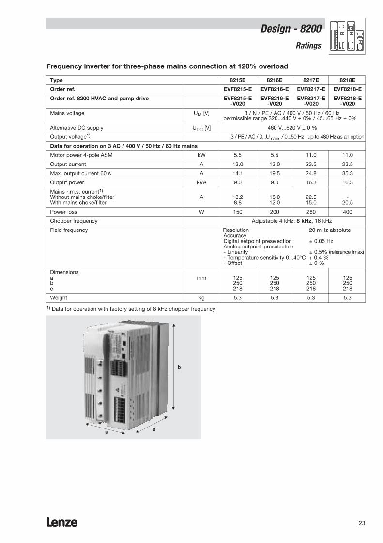
Type 8215E 8216E 8217E 8218E
Order ref. EVF8215-E EVF8216-E EVF8217-E EVF8218-E
Order ref. 8200 HVAC and pump drive EVF8215-E EVF8216-E EVF8217-E EVF8218-E-V020 -V020 -V020 -V020
Mains voltage UM [V] 3 / N / PE / AC / 400 V / 50 Hz / 60 Hzpermissible range 320...440 V ± 0% / 45...65 Hz ± 0%
Alternative DC supply UDC [V] 460 V...620 V ± 0 %
Output voltage1) 3 / PE / AC / 0...Umains / 0...50 Hz , up to 480 Hz as an option
Data for operation on 3 AC / 400 V / 50 Hz / 60 Hz mains
Motor power 4-pole ASM kW 5.5 5.5 11.0 11.0
Output current A 13.0 13.0 23.5 23.5
Max. output current 60 s A 14.1 19.5 24.8 35.3
Output power kVA 9.0 9.0 16.3 16.3
Mains r.m.s. current1)
Without mains choke/filter A 13.2 18.0 22.5 -With mains choke/filter 8.8 12.0 15.0 20.5
Power loss W 150 200 280 400
Chopper frequency Adjustable 4 kHz, 8 kHz, 16 kHz
Field frequency Resolution 20 mHz absoluteAccuracyDigital setpoint preselection ± 0.05 HzAnalog setpoint preselection- Linearity ± 0.5% (reference fmax)- Temperature sensitivity 0...40°C + 0.4 % - Offset ± 0 %
Dimensionsa mm 125 125 125 125b 250 250 250 250e 218 218 218 218
Weight kg 5.3 5.3 5.3 5.3
1) Data for operation with factory setting of 8 kHz chopper frequency
a e
b
Frequency inverter for three-phase mains connection at 120% overload
Design - 8200Ratings

Lenze24
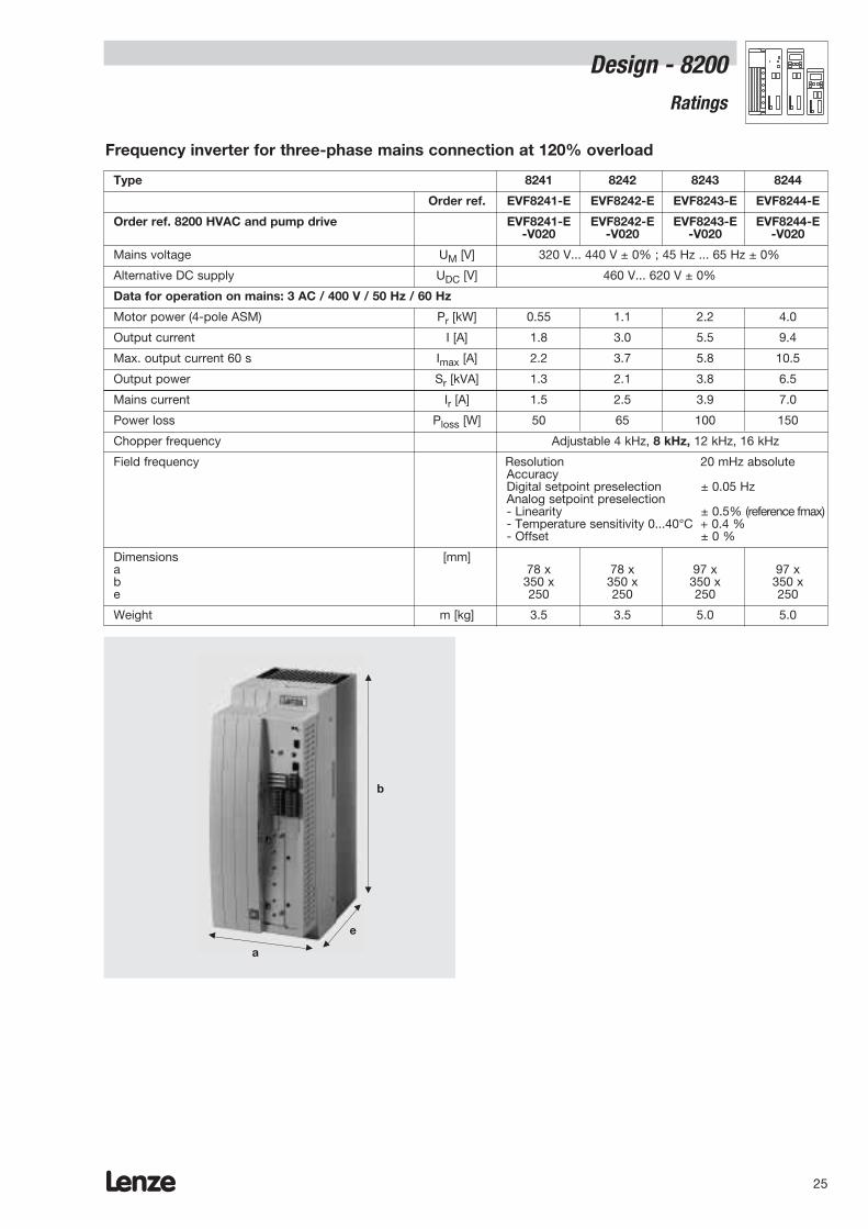
Type 8241 8242 8243 8244
Order ref. EVF8241-E EVF8242-E EVF8243-E EVF8244-E
Order ref. 8200 HVAC and pump drive EVF8241-E EVF8242-E EVF8243-E EVF8244-E-V020 -V020 -V020 -V020
Mains voltage UM [V] 320 V... 528 V ± 0% ; 45 Hz ... 65 Hz ± 0%
Alternative DC supply UDC [V] 460 V... 740 V ± 0%
Data for operation on mains: 3 AC / 400 V / 50 Hz / 60 Hz
Motor power (4-pole ASM) Pr [kW] 0.37 0.75 1.5 3.0
Output current I [A] 1.5 2.5 3.9 7.0
Max. output current 60 s Imax [A] 2.2 3.7 5.8 10.5
Output power Sr [kVA] 1.0 1.7 2.7 4.8
Data for operation on mains: 3 AC / 480 V / 50 Hz / 60 Hz
Motor power (4-pole ASM) Pr [kW] 0.37 0.75 1.5 3.0
Output current I [A] 1.5 2.5 3.9 7.0
Max. output current 60 s Imax [A] 2.25 3.75 5.85 10.5
Output power Sr [kVA] 1.2 2.1 3.2 5.8
Mains current Ir [A] 1.5 2.5 3.9 7.0
Power loss Ploss [W] 50 65 100 150
Chopper frequency Adjustable 4 kHz, 8 kHz, 12 kHz, 16 kHz
Field frequency Resolution 20 mHz absoluteAccuracyDigital setpoint preselection ± 0.05 HzAnalog setpoint preselection- Linearity ± 0.5% (reference fmax)- Temperature sensitivity 0...40°C + 0.4 % - Offset ± 0 %
Dimensions [mm]a 78 x 78 x 97 x 97 xb 350 x 350 x 350 x 350 xe 250 250 250 250
Weight m [kg] 3.5 3.5 5.0 5.0
a
e
b
Frequency inverter for three-phase mains connection at 150% overload
Design - 8200Ratings
Lenze 25
Type 8241 8242 8243 8244
Order ref. EVF8241-E EVF8242-E EVF8243-E EVF8244-E
Order ref. 8200 HVAC and pump drive EVF8241-E EVF8242-E EVF8243-E EVF8244-E-V020 -V020 -V020 -V020
Mains voltage UM [V] 320 V... 440 V ± 0% ; 45 Hz ... 65 Hz ± 0%
Alternative DC supply UDC [V] 460 V... 620 V ± 0%
Data for operation on mains: 3 AC / 400 V / 50 Hz / 60 Hz
Motor power (4-pole ASM) Pr [kW] 0.55 1.1 2.2 4.0
Output current I [A] 1.8 3.0 5.5 9.4
Max. output current 60 s Imax [A] 2.2 3.7 5.8 10.5
Output power Sr [kVA] 1.3 2.1 3.8 6.5
Mains current Ir [A] 1.5 2.5 3.9 7.0
Power loss Ploss [W] 50 65 100 150
Chopper frequency Adjustable 4 kHz, 8 kHz, 12 kHz, 16 kHz
Field frequency Resolution 20 mHz absoluteAccuracyDigital setpoint preselection ± 0.05 HzAnalog setpoint preselection- Linearity ± 0.5% (reference fmax)- Temperature sensitivity 0...40°C + 0.4 % - Offset ± 0 %
Dimensions [mm]a 78 x 78 x 97 x 97 xb 350 x 350 x 350 x 350 xe 250 250 250 250
Weight m [kg] 3.5 3.5 5.0 5.0
a
e
b
Frequency inverter for three-phase mains connection at 120% overload
Design - 8200Ratings
Lenze26
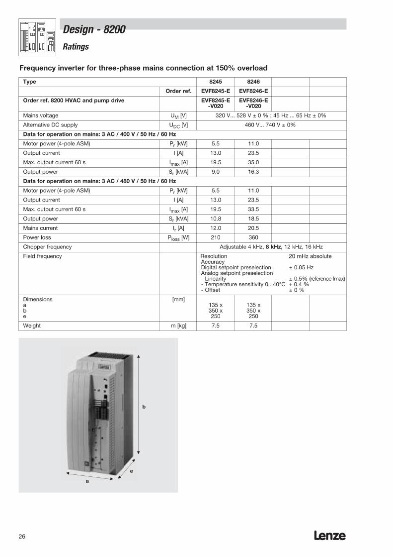
Type 8245 8246
Order ref. EVF8245-E EVF8246-E
Order ref. 8200 HVAC and pump drive EVF8245-E EVF8246-E-V020 -V020
Mains voltage UM [V] 320 V... 528 V ± 0 % ; 45 Hz ... 65 Hz ± 0%
Alternative DC supply UDC [V] 460 V... 740 V ± 0%
Data for operation on mains: 3 AC / 400 V / 50 Hz / 60 Hz
Motor power (4-pole ASM) Pr [kW] 5.5 11.0
Output current I [A] 13.0 23.5
Max. output current 60 s Imax [A] 19.5 35.0
Output power Sr [kVA] 9.0 16.3
Data for operation on mains: 3 AC / 480 V / 50 Hz / 60 Hz
Motor power (4-pole ASM) Pr [kW] 5.5 11.0
Output current I [A] 13.0 23.5
Max. output current 60 s Imax [A] 19.5 33.5
Output power Sr [kVA] 10.8 18.5
Mains current Ir [A] 12.0 20.5
Power loss Ploss [W] 210 360
Chopper frequency Adjustable 4 kHz, 8 kHz, 12 kHz, 16 kHz
Field frequency Resolution 20 mHz absoluteAccuracyDigital setpoint preselection ± 0.05 HzAnalog setpoint preselection- Linearity ± 0.5% (reference fmax)- Temperature sensitivity 0...40°C + 0.4 % - Offset ± 0 %
Dimensions [mm]a 135 x 135 xb 350 x 350 xe 250 250
Weight m [kg] 7.5 7.5
Frequency inverter for three-phase mains connection at 150% overload
a
e
b
Design - 8200Ratings
Lenze 27
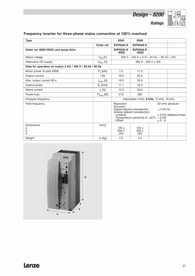
Type 8245 8246
Order ref. EVF8245-E EVF8246-E
Order ref. 8200 HVAC and pump drive EVF8245-E EVF8246-E-V020 -V020
Mains voltage UM [V] 320 V... 440 V ± 0 % ; 45 Hz ... 65 Hz ± 0%
Alternative DC supply UDC [V] 460 V... 620 V ± 0%
Data for operation on mains: 3 AC / 400 V / 50 Hz / 60 Hz
Motor power (4-pole ASM) Pr [kW] 7.5 11.0
Output current I [A] 16.0 23.5
Max. output current 60 s Imax [A] 19.5 35.0
Output power Sr [kVA] 11.1 16.3
Mains current Ir [A] 12.0 20.5
Power loss Ploss [W] 210 360
Chopper frequency Adjustable 4 kHz, 8 kHz, 12 kHz, 16 kHz
Field frequency Resolution 20 mHz absoluteAccuracy Digital setpoint preselection ± 0.05 HzAnalog setpoint preselection- Linearity ± 0.5% (reference fmax)- Temperature sensitivity 0...40°C + 0.4% - Offset ± 0 %
Dimensions [mm]a 135 x 135 xb 350 x 350 xe 250 250
Weight m [kg] 7.5 7.5
Frequency inverter for three-phase mains connection at 120% overload
a
e
b
Design - 8200Ratings
Lenze28
Design - 8200Ratings
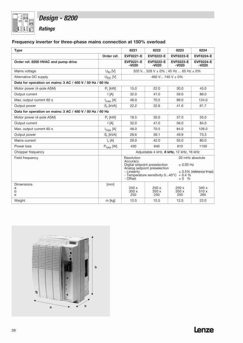
Type 8221 8222 8223 8224
Order ref. EVF8221-E EVF8222-E EVF8223-E EVF8224-E
Order ref. 8200 HVAC and pump drive EVF8221-E EVF8222-E EVF8223-E EVF8224-E-V020 -V020 -V020 -V020
Mains voltage UM [V] 320 V... 528 V ± 0% ; 45 Hz ... 65 Hz ± 0%
Alternative DC supply UDC [V] 460 V... 740 V ± 0%
Data for operation on mains: 3 AC / 400 V / 50 Hz / 60 Hz
Motor power (4-pole ASM) Pr [kW] 15.0 22.0 30.0 45.0
Output current I [A] 32.0 47.0 59.0 89.0
Max. output current 60 s Imax [A] 48.0 70.5 89.0 134.0
Output power Sr [kVA] 22.2 32.6 41.6 61.7
Data for operation on mains: 3 AC / 480 V / 50 Hz / 60 Hz
Motor power (4-pole ASM) Pr [kW] 18.5 30.0 37.0 55.0
Output current I [A] 32.0 47.0 56.0 84.0
Max. output current 60 s Imax [A] 48.0 70.5 84.0 126.0
Output power Sr [kVA] 26.6 39.1 49.9 73.3
Mains current Ir [A] 29.0 42.0 55.0 80.0
Power loss Ploss [W] 430 640 810 1100
Chopper frequency Adjustable 4 kHz, 8 kHz, 12 kHz, 16 kHz
Field frequency Resolution 20 mHz absoluteAccuracyDigital setpoint preselection ± 0.05 HzAnalog setpoint preselection- Linearity ± 0.5% (reference fmax)- Temperature sensitivity 0...40°C + 0.4 % - Offset ± 0 %
Dimensions [mm]a 250 x 250 x 250 x 340 xb 350 x 350 x 350 x 510 xe 250 250 250 285
Weight m [kg] 12.5 12.5 12.5 22.0
Frequency inverter for three-phase mains connection at 150% overload
a e
b

Lenze 29
Type 8221 8222 8223 8224
Order ref. EVF8221-E EVF8222-E EVF8223-E EVF8224-E
Order ref. 8200 HVAC and pump drive EVF8221-E EVF8222-E EVF8223-E EVF8224-E-V020 -V020 -V020 -V020
Mains voltage UM [V] 320 V... 440 V ± 0% ; 45 Hz ... 65 Hz ± 0%
Alternative DC supply UDC [V] 460 V... 620 V ± 0%
Data for operation on mains: 3 AC / 400 V / 50 Hz / 60 Hz
Motor power (4-pole ASM) Pr [kW] 22.0 30.0 37.5 55.0
Output current I [A] 43.0 56.0 66.0 100.0
Max. output current 60 s Imax [A] 48.0 70.5 89.0 134.0
Output power Sr [kVA] 29.8 39.5 46.4 74.8
Mains current Ir [A] 29.0 42.0 55.0 80.0
Power loss Ploss [W] 430 640 810 1100
Chopper frequency Adjustable 4 kHz, 8 kHz, 12 kHz, 16 kHz
Field frequency Resolution 20 mHz absoluteAccuracyDigital setpoint preselection ± 0.05 HzAnalog setpoint preselection- Linearity ± 0.5% (reference fmax)- Temperature sensitivity 0...40°C + 0.4 % - Offset ± 0 %
Dimensions [mm]a 250 x 250 x 250 x 340 xb 350 x 350 x 350 x 510 xe 250 250 250 285
Weight m [kg] 12.5 12.5 12.5 22.0
Frequency inverter for three-phase mains connection at 120% overload
a e
b
Design - 8200Ratings
Lenze30
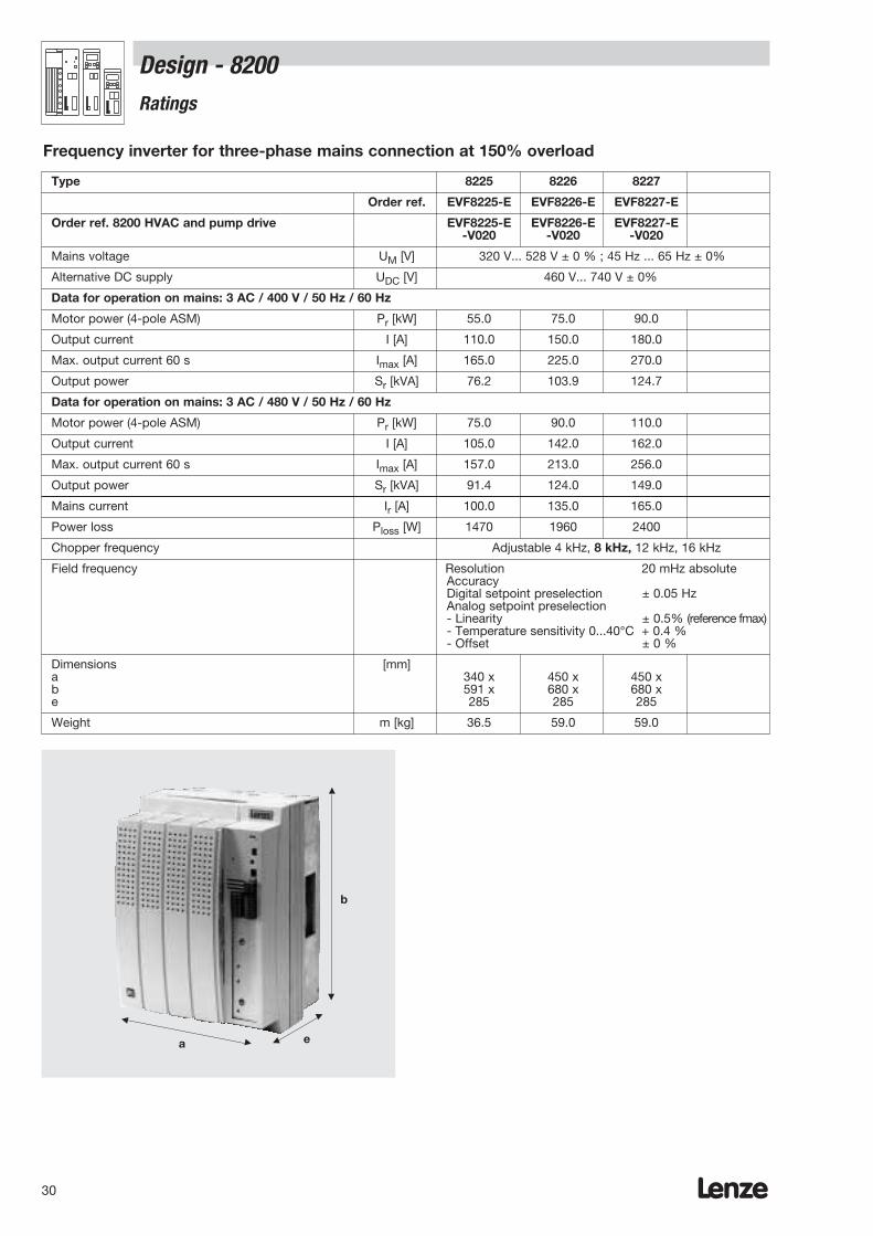
Type 8225 8226 8227
Order ref. EVF8225-E EVF8226-E EVF8227-E
Order ref. 8200 HVAC and pump drive EVF8225-E EVF8226-E EVF8227-E -V020 -V020 -V020
Mains voltage UM [V] 320 V... 528 V ± 0 % ; 45 Hz ... 65 Hz ± 0%
Alternative DC supply UDC [V] 460 V... 740 V ± 0%
Data for operation on mains: 3 AC / 400 V / 50 Hz / 60 Hz
Motor power (4-pole ASM) Pr [kW] 55.0 75.0 90.0
Output current I [A] 110.0 150.0 180.0
Max. output current 60 s Imax [A] 165.0 225.0 270.0
Output power Sr [kVA] 76.2 103.9 124.7
Data for operation on mains: 3 AC / 480 V / 50 Hz / 60 Hz
Motor power (4-pole ASM) Pr [kW] 75.0 90.0 110.0
Output current I [A] 105.0 142.0 162.0
Max. output current 60 s Imax [A] 157.0 213.0 256.0
Output power Sr [kVA] 91.4 124.0 149.0
Mains current Ir [A] 100.0 135.0 165.0
Power loss Ploss [W] 1470 1960 2400
Chopper frequency Adjustable 4 kHz, 8 kHz, 12 kHz, 16 kHz
Field frequency Resolution 20 mHz absoluteAccuracyDigital setpoint preselection ± 0.05 HzAnalog setpoint preselection- Linearity ± 0.5% (reference fmax)- Temperature sensitivity 0...40°C + 0.4 % - Offset ± 0 %
Dimensions [mm]a 340 x 450 x 450 xb 591 x 680 x 680 xe 285 285 285
Weight m [kg] 36.5 59.0 59.0
Frequency inverter for three-phase mains connection at 150% overload
a e
b
Design - 8200Ratings
Lenze 31
Design - 8200Ratings
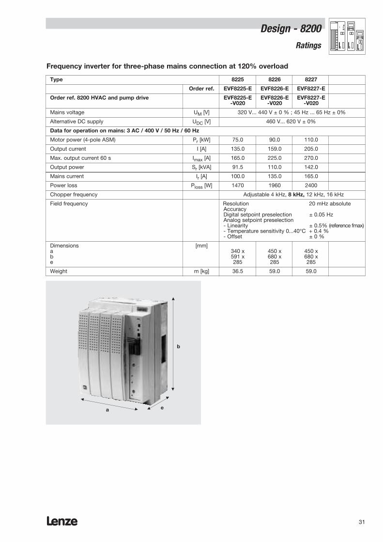
Frequency inverter for three-phase mains connection at 120% overload
a e
b
Type 8225 8226 8227
Order ref. EVF8225-E EVF8226-E EVF8227-E
Order ref. 8200 HVAC and pump drive EVF8225-E EVF8226-E EVF8227-E -V020 -V020 -V020
Mains voltage UM [V] 320 V... 440 V ± 0 % ; 45 Hz ... 65 Hz ± 0%
Alternative DC supply UDC [V] 460 V... 620 V ± 0%
Data for operation on mains: 3 AC / 400 V / 50 Hz / 60 Hz
Motor power (4-pole ASM) Pr [kW] 75.0 90.0 110.0
Output current I [A] 135.0 159.0 205.0
Max. output current 60 s Imax [A] 165.0 225.0 270.0
Output power Sr [kVA] 91.5 110.0 142.0
Mains current Ir [A] 100.0 135.0 165.0
Power loss Ploss [W] 1470 1960 2400
Chopper frequency Adjustable 4 kHz, 8 kHz, 12 kHz, 16 kHz
Field frequency Resolution 20 mHz absoluteAccuracyDigital setpoint preselection ± 0.05 HzAnalog setpoint preselection- Linearity ± 0.5% (reference fmax)- Temperature sensitivity 0...40°C + 0.4 % - Offset ± 0 %
Dimensions [mm]a 340 x 450 x 450 xb 591 x 680 x 680 xe 285 285 285
Weight m [kg] 36.5 59.0 59.0
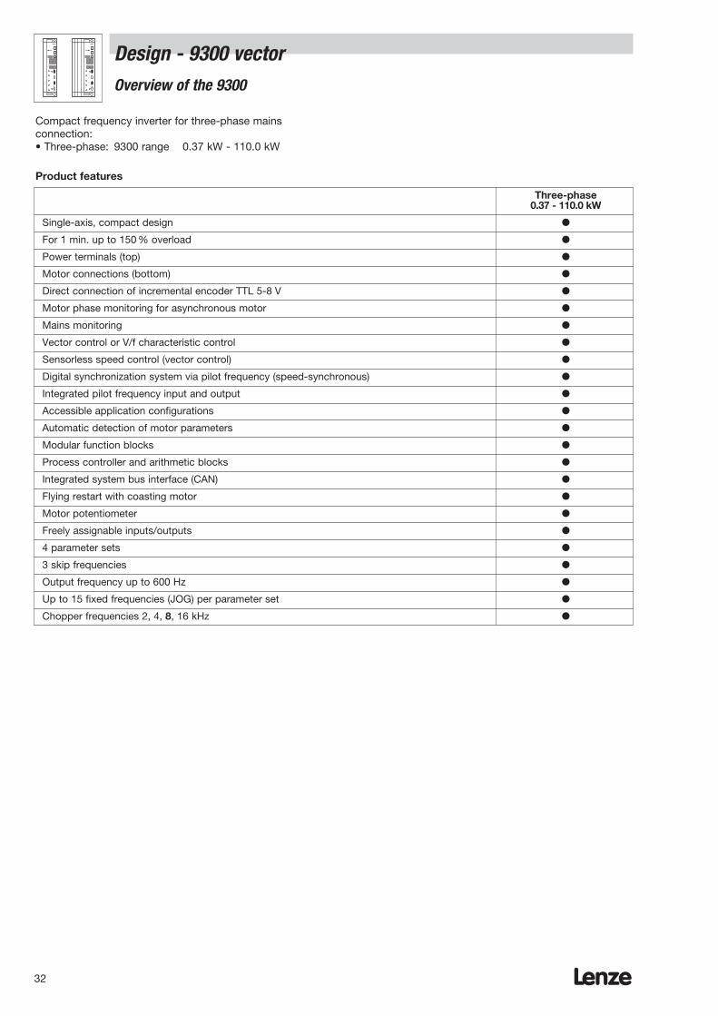
Lenze32
Three-phase0.37 - 110.0 kW
Single-axis, compact design
For 1 min. up to 150 % overload
Power terminals (top)
Motor connections (bottom)
Direct connection of incremental encoder TTL 5-8 V
Motor phase monitoring for asynchronous motor
Mains monitoring
Vector control or V/f characteristic control
Sensorless speed control (vector control)
Digital synchronization system via pilot frequency (speed-synchronous)
Integrated pilot frequency input and output
Accessible application configurations
Automatic detection of motor parameters
Modular function blocks
Process controller and arithmetic blocks
Integrated system bus interface (CAN)
Flying restart with coasting motor
Motor potentiometer
Freely assignable inputs/outputs
4 parameter sets
3 skip frequencies
Output frequency up to 600 Hz
Up to 15 fixed frequencies (JOG) per parameter set
Chopper frequencies 2, 4, 8, 16 kHz
Compact frequency inverter for three-phase mainsconnection:• Three-phase: 9300 range 0.37 kW - 110.0 kW
Product features
Design - 9300 vector Overview of the 9300

Lenze 33
Design - 9300 vector General data
Range Values
Vibration resistance Germanischer Lloyd, general conditions
Humidity Humidity class F, no condensation (average relative humidity 85%)
Permissible temperature ranges During device transport: -25 ° C + 7 0 ° CDuring device storage: -25 °C ... + 55 °CDuring device operation: 0 ° C ... + 40 °C
+40 ° C ... + 50 ° C with power derating 2.5% per K
Permissible installation height h Up to 1000 m above sea level Without power derating1000 m above sea level ... 4000 m above sea level 5%/1000m
Pollution degree VDE 0110 Part 2 pollution degree 2
Noise emission Requirements to EN 50081-1, EN 50081-2, IEC 22G-WG4 (Cv) 21Limiting value class A to EN 55011 (industrial area) with mains filterLimiting value class B to EN 55022 (residential area) withmains filter and control cabinet installation
Noise immunity Complies with limit values with mains filterRequirements to EN 50082-2, IEC 22G-WG4 (Cv) 21Requirements Standard Intensity of testsESD EN61000-4-2 3, i.e. 8 kV with air discharge
and 6 kV with contact dischargeHF field(housing) EN61000-4-3 3, i.e. 10 V/m; 27 up to 1000 MHzBurst EN61000-4-4 3/4, i.e. 2 kV/5 kHzSurge(on mains cable) IEC 1000-4-5 3, i.e. 1.2/50 µs 1 kV phase-phase, 2 kV phase-PE
Insulation strength Overvoltage category III to VDE 0110
Packaging To DIN 4180- 9321 to 9333EV: Shipping container
Degree of protection IP20NEMA 1: Protection against contact
Approvals CE: Low voltage directiveUL508: Industrial Control EquipmentUL508C: Power Conversion Equipment
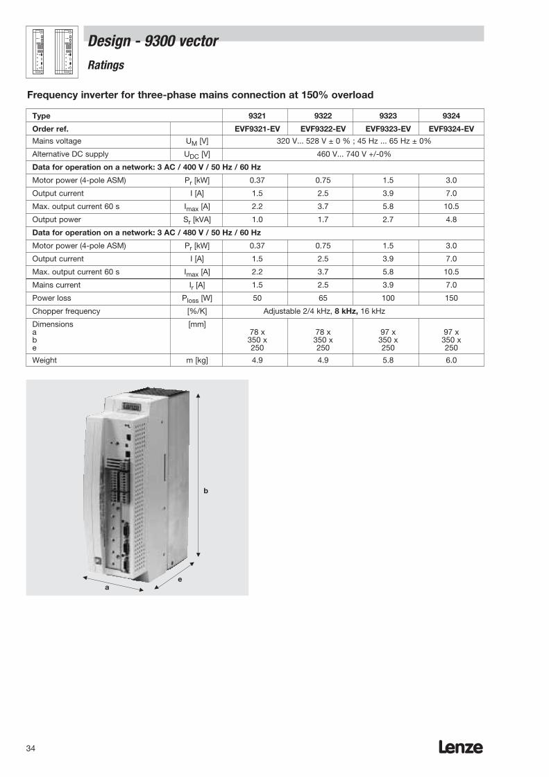
Lenze34
Type 9321 9322 9323 9324
Order ref. EVF9321-EV EVF9322-EV EVF9323-EV EVF9324-EV
Mains voltage UM [V] 320 V... 528 V ± 0 % ; 45 Hz ... 65 Hz ± 0%
Alternative DC supply UDC [V] 460 V... 740 V +/-0%
Data for operation on a network: 3 AC / 400 V / 50 Hz / 60 Hz
Motor power (4-pole ASM) Pr [kW] 0.37 0.75 1.5 3.0
Output current I [A] 1.5 2.5 3.9 7.0
Max. output current 60 s Imax [A] 2.2 3.7 5.8 10.5
Output power Sr [kVA] 1.0 1.7 2.7 4.8
Data for operation on a network: 3 AC / 480 V / 50 Hz / 60 Hz
Motor power (4-pole ASM) Pr [kW] 0.37 0.75 1.5 3.0
Output current I [A] 1.5 2.5 3.9 7.0
Max. output current 60 s Imax [A] 2.2 3.7 5.8 10.5
Mains current Ir [A] 1.5 2.5 3.9 7.0
Power loss Ploss [W] 50 65 100 150
Chopper frequency [%/K] Adjustable 2/4 kHz, 8 kHz, 16 kHz
Dimensions [mm]a 78 x 78 x 97 x 97 xb 350 x 350 x 350 x 350 xe 250 250 250 250
Weight m [kg] 4.9 4.9 5.8 6.0
Frequency inverter for three-phase mains connection at 150% overload
Design - 9300 vector Ratings
ae
b

Lenze 35
Type 9321 9322 9323 9324
Order ref. EVF9321-EV EVF9322-EV EVF9323-EV EVF9324-EV
Mains voltage UM [V] 320 V... 528 V ± 0% ; 45 Hz ... 65 Hz ± 0%
Alternative DC supply UDC [V] 460 V... 620 V ± 0%
Data for operation on mains: 3 AC / 400 V / 50 Hz / 60 Hz
Motor power (4-pole ASM) Pr [kW] 0.55 1.1 2.2 4.0
Output current I [A] 1.8 3.0 5.5 9.2
Max. output current 60 s Imax [A] 2.2 3.7 5.8 10.5
Output power Sr [kVA] 1.3 2.1 3.8 6.5
Mains current Ir [A] 1.5 2.5 3.9 7.0
Power loss Ploss [W] 50 65 100 150
Chopper frequency Adjustable 2/4 kHz, 8 kHz, 16 kHz
Dimensions [mm]a 78 x 78 x 97 x 97 xb 350 x 350 x 350 x 350 xe 250 250 250 250
Weight m [kg] 4.9 4.9 5.8 6.0
Frequency inverter for three-phase mains connection at 120% overload
Design - 9300 vector Ratings
ae
b

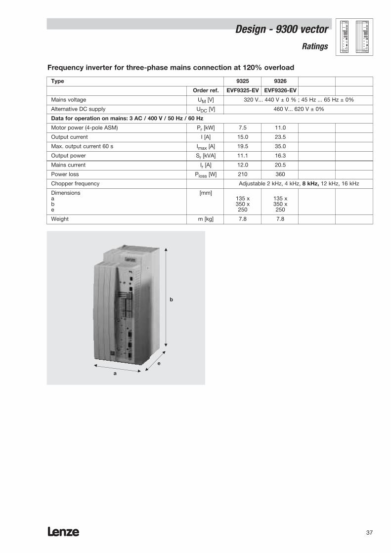
Lenze36
Design - 9300 vectorRatings
Type 9325 9326
Order ref. EVF9325-EV EVF9326-EV
Mains voltage UM [V] 320 V... 528 V ± 0 % ; 45 Hz ... 65 Hz ± 0%
Alternative DC supply UDC [V] 460 V... 740 V ± 0%
Data for operation on mains: 3 AC / 400 V / 50 Hz / 60 Hz
Motor power (4-pole ASM) Pr [kW] 5.5 11.0
Output current I [A] 13.0 23.5
Max. output current 60 s Imax [A] 19.5 35.0
Output power Sr [kVA] 9.0 16.3
Data for operation on mains: 3 AC / 480 V / 50 Hz / 60 Hz
Motor power (4-pole ASM) Pr [kW] 5.5 11.0
Output current I [A] 13.0 22.3
Max. output current 60 s Imax [A] 19.5 33.5
Output power Sr [kVA] 10.8 18.5
Mains current Ir [A] 12.0 20.5
Power loss Ploss [W] 210 360
Chopper frequency Adjustable 4 kHz, 8 kHz, 16 kHz
Dimensions [mm]a 135 x 135 xb 350 x 350 xe 250 250
Weight m [kg] 7.8 7.8
Frequency inverter for three-phase mains connection at 150% overload
a
e
b
Lenze 37
Type 9325 9326
Order ref. EVF9325-EV EVF9326-EV
Mains voltage UM [V] 320 V... 440 V ± 0 % ; 45 Hz ... 65 Hz ± 0%
Alternative DC supply UDC [V] 460 V... 620 V ± 0%
Data for operation on mains: 3 AC / 400 V / 50 Hz / 60 Hz
Motor power (4-pole ASM) Pr [kW] 7.5 11.0
Output current I [A] 15.0 23.5
Max. output current 60 s Imax [A] 19.5 35.0
Output power Sr [kVA] 11.1 16.3
Mains current Ir [A] 12.0 20.5
Power loss Ploss [W] 210 360
Chopper frequency Adjustable 2 kHz, 4 kHz, 8 kHz, 12 kHz, 16 kHz
Dimensions [mm]a 135 x 135 xb 350 x 350 xe 250 250
Weight m [kg] 7.8 7.8
Frequency inverter for three-phase mains connection at 120% overload
a
e
b
Design - 9300 vector Ratings
Lenze38
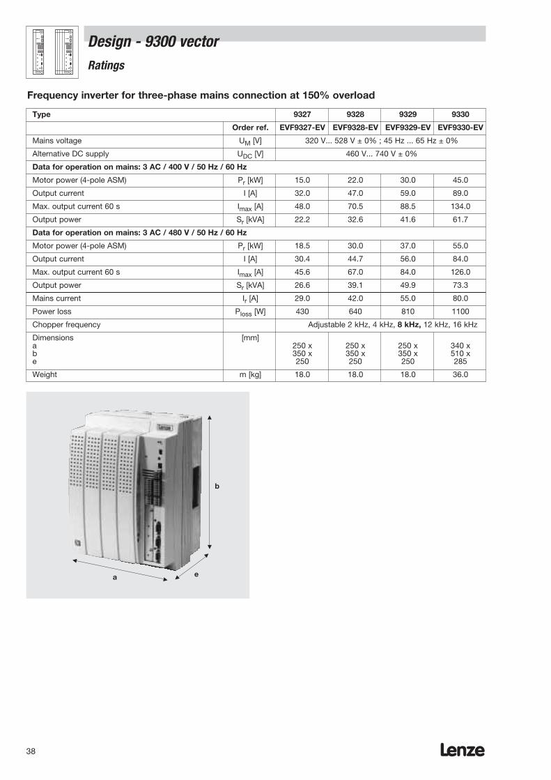
Design - 9300 vectorRatings
Type 9327 9328 9329 9330
Order ref. EVF9327-EV EVF9328-EV EVF9329-EV EVF9330-EV
Mains voltage UM [V] 320 V... 528 V ± 0% ; 45 Hz ... 65 Hz ± 0%
Alternative DC supply UDC [V] 460 V... 740 V ± 0%
Data for operation on mains: 3 AC / 400 V / 50 Hz / 60 Hz
Motor power (4-pole ASM) Pr [kW] 15.0 22.0 30.0 45.0
Output current I [A] 32.0 47.0 59.0 89.0
Max. output current 60 s Imax [A] 48.0 70.5 88.5 134.0
Output power Sr [kVA] 22.2 32.6 41.6 61.7
Data for operation on mains: 3 AC / 480 V / 50 Hz / 60 Hz
Motor power (4-pole ASM) Pr [kW] 18.5 30.0 37.0 55.0
Output current I [A] 30.4 44.7 56.0 84.0
Max. output current 60 s Imax [A] 45.6 67.0 84.0 126.0
Output power Sr [kVA] 26.6 39.1 49.9 73.3
Mains current Ir [A] 29.0 42.0 55.0 80.0
Power loss Ploss [W] 430 640 810 1100
Chopper frequency Adjustable 2 kHz, 4 kHz, 8 kHz, 12 kHz, 16 kHz
Dimensions [mm]a 250 x 250 x 250 x 340 xb 350 x 350 x 350 x 510 xe 250 250 250 285
Weight m [kg] 18.0 18.0 18.0 36.0
Frequency inverter for three-phase mains connection at 150% overload
a e
b

Lenze 39
Design - 9300 vector Ratings
Type 9327 9328 9329 9330
Order ref. EVF9327-EV EVF9328-EV EVF9329-EV EVF9330-EV
Mains voltage UM [V] 320 V... 440 V ± 0% ; 45 Hz ... 65 Hz ± 0%
Alternative DC supply UDC [V] 460 V... 620 V ± 0%
Data for operation on mains: 3 AC / 400 V / 50 Hz / 60 Hz
Motor power (4-pole ASM) Pr [kW] 22.0 30.0 37.5 55.0
Output current I [A] 43.0 56.0 66.0 100
Max. output current 60 s Imax [A] 48.0 70.5 88.5 134.0
Output power Sr [kVA] 29.8 39.5 46.4 74.8
Mains current Ir [A] 29.0 42.0 55.0 80.0
Power loss Ploss [W] 430 640 810 1100
Chopper frequency Adjustable 2 kHz, 4 kHz, 8 kHz, 16 kHz
Dimensions [mm]a 250 x 250 x 250 x 340 xb 350 x 350 x 350 x 510 xe 250 250 250 285
Weight m [kg] 18.0 18.0 18.0 36.0
Frequency inverter for three-phase mains connection at 120% overload
a e
b
Lenze40
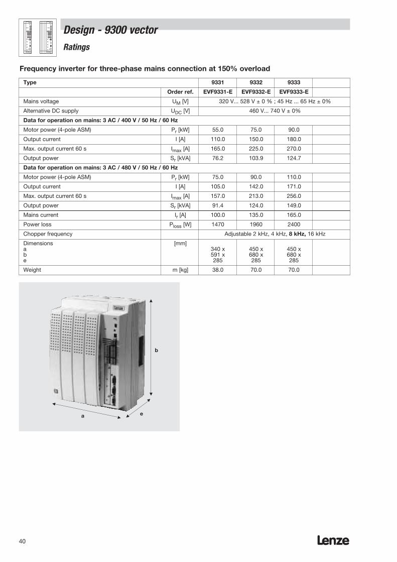
Design - 9300 vectorRatings
Type 9331 9332 9333
Order ref. EVF9331-E EVF9332-E EVF9333-E
Mains voltage UM [V] 320 V... 528 V ± 0 % ; 45 Hz ... 65 Hz ± 0%
Alternative DC supply UDC [V] 460 V... 740 V ± 0%
Data for operation on mains: 3 AC / 400 V / 50 Hz / 60 Hz
Motor power (4-pole ASM) Pr [kW] 55.0 75.0 90.0
Output current I [A] 110.0 150.0 180.0
Max. output current 60 s Imax [A] 165.0 225.0 270.0
Output power Sr [kVA] 76.2 103.9 124.7
Data for operation on mains: 3 AC / 480 V / 50 Hz / 60 Hz
Motor power (4-pole ASM) Pr [kW] 75.0 90.0 110.0
Output current I [A] 105.0 142.0 171.0
Max. output current 60 s Imax [A] 157.0 213.0 256.0
Output power Sr [kVA] 91.4 124.0 149.0
Mains current Ir [A] 100.0 135.0 165.0
Power loss Ploss [W] 1470 1960 2400
Chopper frequency Adjustable 2 kHz, 4 kHz, 8 kHz, 16 kHz
Dimensions [mm]a 340 x 450 x 450 xb 591 x 680 x 680 xe 285 285 285
Weight m [kg] 38.0 70.0 70.0
Frequency inverter for three-phase mains connection at 150% overload
a e
b
Lenze 41
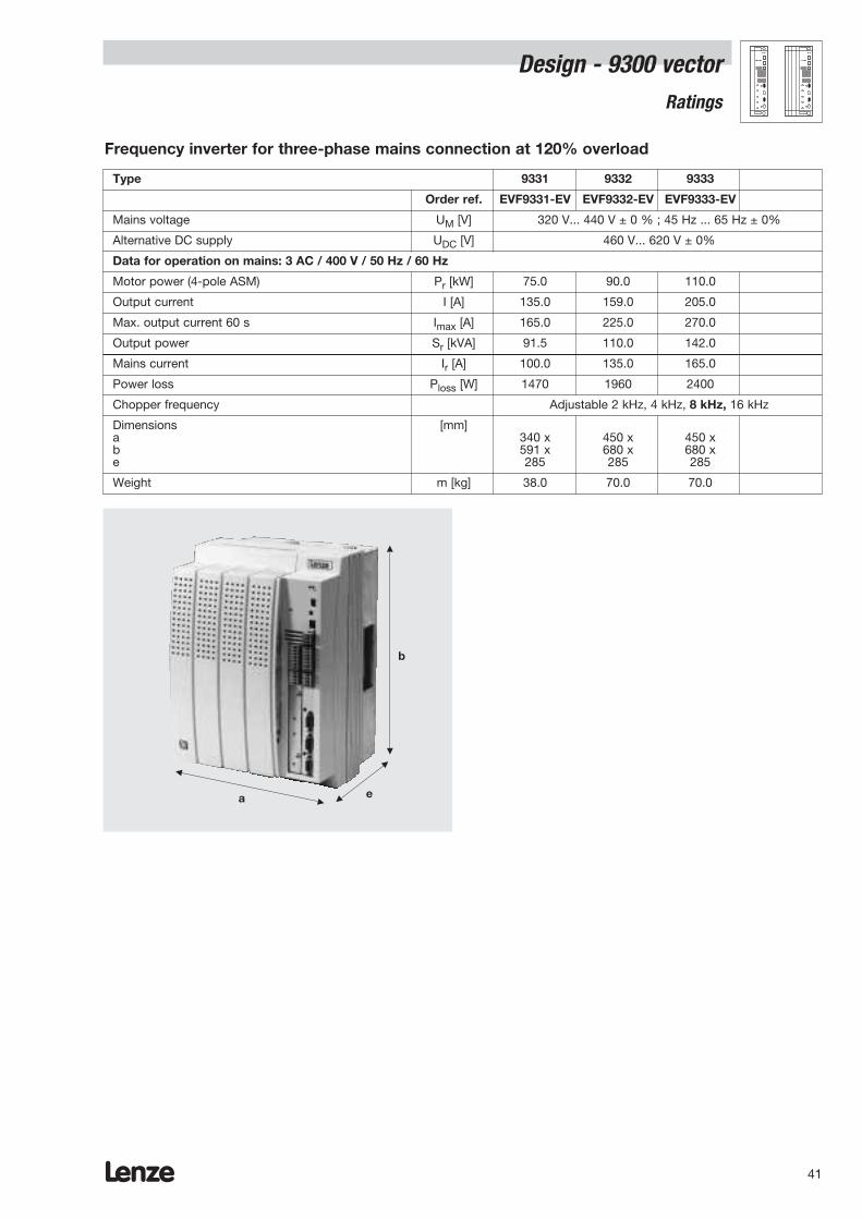
Design - 9300 vector Ratings
Type 9331 9332 9333
Order ref. EVF9331-EV EVF9332-EV EVF9333-EV
Mains voltage UM [V] 320 V... 440 V ± 0 % ; 45 Hz ... 65 Hz ± 0%
Alternative DC supply UDC [V] 460 V... 620 V ± 0%
Data for operation on mains: 3 AC / 400 V / 50 Hz / 60 Hz
Motor power (4-pole ASM) Pr [kW] 75.0 90.0 110.0
Output current I [A] 135.0 159.0 205.0
Max. output current 60 s Imax [A] 165.0 225.0 270.0
Output power Sr [kVA] 91.5 110.0 142.0
Mains current Ir [A] 100.0 135.0 165.0
Power loss Ploss [W] 1470 1960 2400
Chopper frequency Adjustable 2 kHz, 4 kHz, 8 kHz, 16 kHz
Dimensions [mm]a 340 x 450 x 450 xb 591 x 680 x 680 xe 285 285 285
Weight m [kg] 38.0 70.0 70.0
Frequency inverter for three-phase mains connection at 120% overload
a e
b

Lenze42
Lenze 43
Design - 8200 and 9300 vector Mechanical installation
General information
– 8200 vector frequency inverters must only be used asbuilt-in units.
– If the exhaust air contains pollutants (dust, lint, grease,aggressive gases) then appropriate counter-measuresmust be in place (e.g. installation of filters, regularcleaning etc.).
– Ensure there is enough mounting space.Several units can be mounted directly adjacent to oneanother without clearance.Ensure that there is free access for cooling air andthat the outlet for used air is not blocked.Ensure clearance of 100 mm above and below.
– In the event of continuous oscillations or vibrations,check the use of vibration dampers.
The frequency inverters can be fitted as follows into acontrol cabinet:
With the fixing rails included in the scope of supplyWith a DIN rail mounting up to 3.0 kWWith thermal separation from 4.0 kW upwardsWith special fixing devices
Lenze44
Design - 8200 and 9300 vectorAssembly with fixing rail
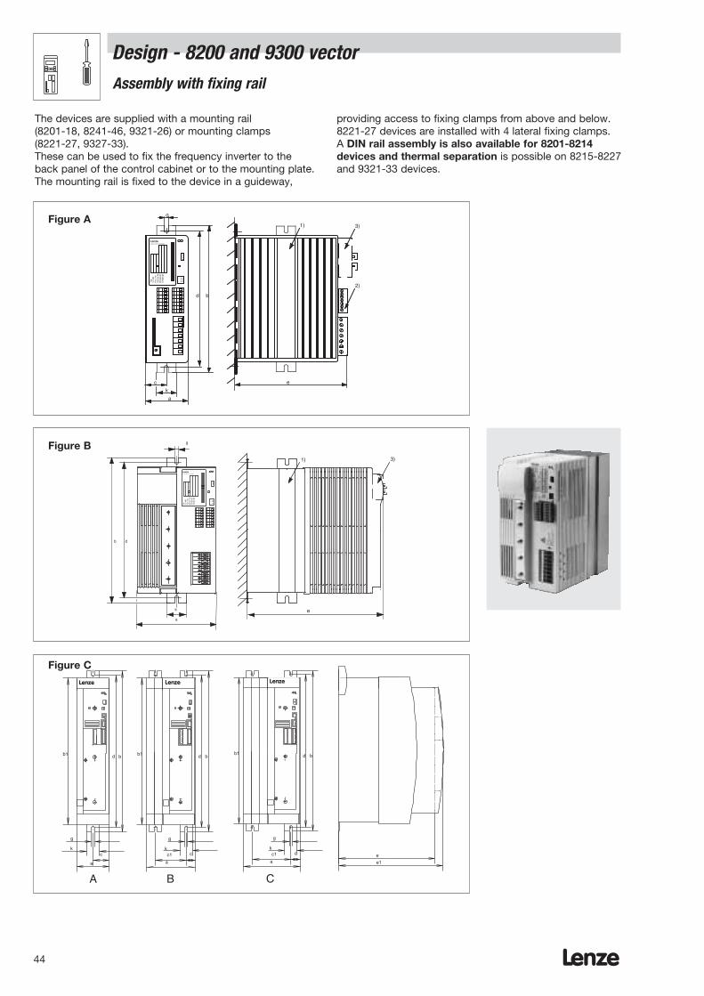
The devices are supplied with a mounting rail (8201-18, 8241-46, 9321-26) or mounting clamps (8221-27, 9327-33). These can be used to fix the frequency inverter to theback panel of the control cabinet or to the mounting plate.The mounting rail is fixed to the device in a guideway,
providing access to fixing clamps from above and below.8221-27 devices are installed with 4 lateral fixing clamps.A DIN rail assembly is also available for 8201-8214devices and thermal separation is possible on 8215-8227and 9321-33 devices.
g
Typ
Id.-
NR
Fer
t.-N
rS
erie
n-N
r.E
inga
ng1
Ein
gang
2
LenzePostfach 101352 ,31763 HAMELN
c
k
a
e
d b
1)
2)
3)
Typ
Id.-
NR
Fer
t.-N
rS
erie
n-N
r.E
inga
ng1
Ein
gang
2
LenzePostfach 101352 ,31763 HAMELN
k
a
g
b d
e
1) 3)
e1
e
b1 b1bd bd
g
k
a
c
g
k
a
cc1
b1 bd
g
k
a
cc1
Lenze
A B C
Lenze Lenze
Figure A
Figure B
Figure CLenze Lenze Lenze

Lenze 45
Design - 8200 and 9300 vector Assembly with fixing rail
Device Figure a b b1 c c1 d d1 e g k m[mm] [mm] [mm] [mm] [mm] [mm] [mm] [mm] [mm] [mm] [mm]
8201E A 64 210 – 29 – 190 – 158 6.5 30 –
8202E A 64 210 – 29 – 190 – 198 6.5 30 –
8202E-V002 A 64 210 – 29 – 190 – 158 6.5 30 –
8203E A 83 283 – 38 – 263 – 211 6.5 30 –
8204E A 83 283 – 38 – 263 – 211 6.5 30 –
8211E A 83 283 – 38 – 263 – 211 6.5 30 –
8212E A 83 283 – 38 – 263 – 211 6.5 30 –
8213E A 83 283 – 38 – 263 – 211 6.5 30 –
8214E A 83 283 – 38 – 263 – 211 6.5 30 –
8215E B 125 283 – – – 263 – 218 6.5 30 –
8216E B 125 283 – – – 263 – 218 6.5 30 –
8217E B 125 283 – – – 263 – 218 6.5 30 –
8218E B 125 283 – – – 263 – 218 6.5 30 –
8241E/9321EV C 78 384 350 39 – 365 – 250 6.5 30 –
8242E/9322EV C 78 384 350 39 – 365 – 250 6.5 30 –
8243E/9323EV C 97 384 350 48.5 – 365 – 250 6.5 30 –
8244E/9324EV C 97 384 350 48.5 – 365 – 250 6.5 30 –
8245E/9325EV C 135 384 350 21.5 92 365 – 250 6.5 30 –
8246E/9326EV C 135 384 350 21.5 92 365 – 250 6.5 30 –
8221E/9327EV D 250 402 350 22 205 370 24 250 6.5 – 11.0
8222E/9328EV D 250 402 350 22 205 370 24 250 6.5 – 11.0
8223E/9329EV D 250 402 350 22 205 370 24 250 6.5 – 11.0
8224E/9330EV D 340 580 510 28 284 532 38 285 11.0 – 18.0
8225E/9331EV D 340 672 591 28 284 624 38 285 11.0 – 18.0
8226E/9332EV D 450 750 680 30.5 395 702 38 285 11.0 – 18.0
8227E/9333EV D 450 750 680 30.5 395 702 38 285 11.0 – 18.0
a
b
e
b1
gm
c
d1
c1
d
(x)
Lenze
Figure D

Lenze46

Lenze 47
Design - 8200 and 9300 vector Mounting with DIN rail assembly
A special bracket can be used to fix 8201-8214 devices totwo DIN rails (H1, H2).
8201/02 devices can also be fixed with one DIN rail (H3).Alternatively, the controller can be installed using a fixing rail.
Device a b c d e f[mm] [mm] [mm] [mm] [mm] [mm]
8201E 64 180 16 125 173 98
8202E 64 180 16 125 213 98
8203E 83 250 16 125 237 –
8204E 83 250 16 125 237 –
8211E 83 250 16 125 226 –
8212E 83 250 16 125 226 –
8213E 83 250 16 125 226 –
8214E 83 250 16 125 226 –
H1
H3
H2
Lenze48
Design - 8200 and 9300 vectorAssembly with thermal separation (push-through technology)
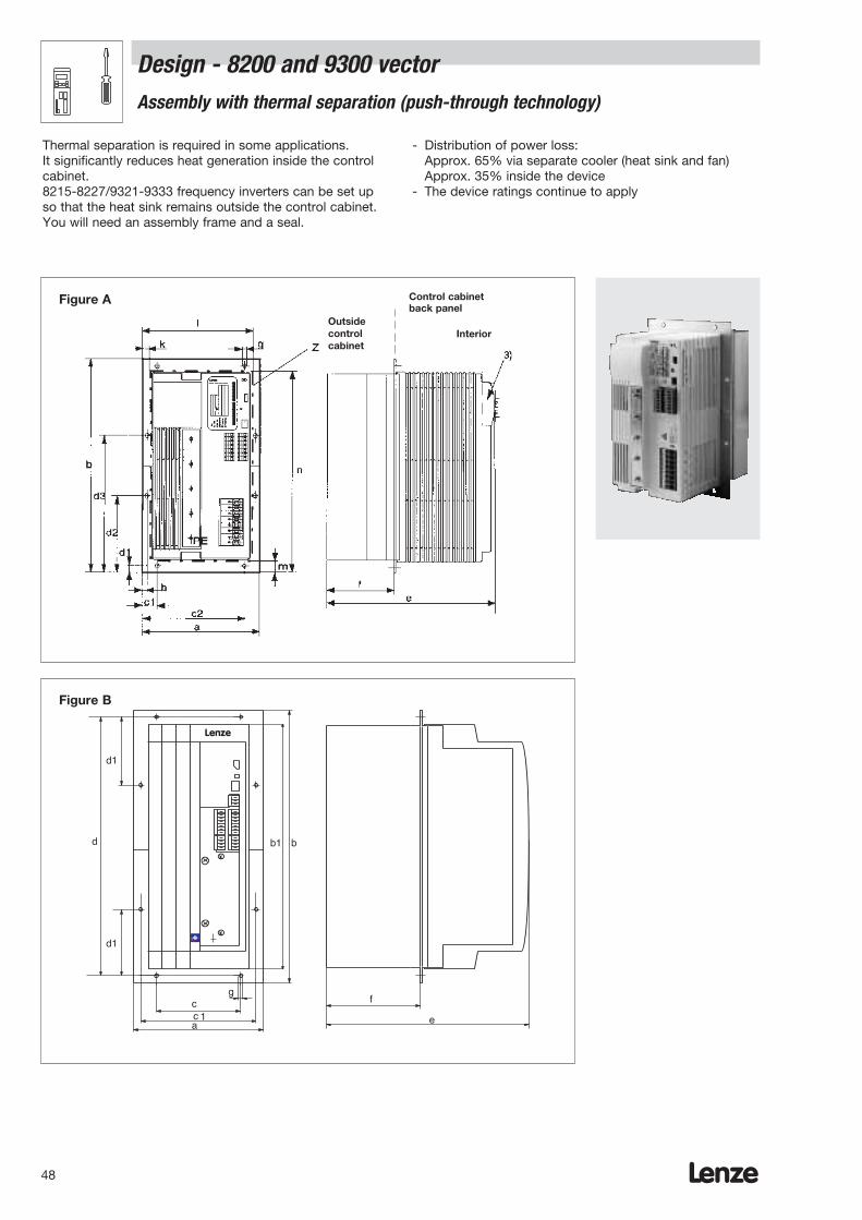
Thermal separation is required in some applications. It significantly reduces heat generation inside the controlcabinet. 8215-8227/9321-9333 frequency inverters can be set upso that the heat sink remains outside the control cabinet.You will need an assembly frame and a seal.
- Distribution of power loss:Approx. 65% via separate cooler (heat sink and fan)Approx. 35% inside the device
- The device ratings continue to apply
c
bd
e
g
L
ca
1
d1
d1
f
b1
Control cabinetback panel
Figure A
Figure B
Outsidecontrolcabinet
Interior
Lenze
Lenze 49
Design - 8200 and 9300 vector Assembly with thermal separation (push-through technology)
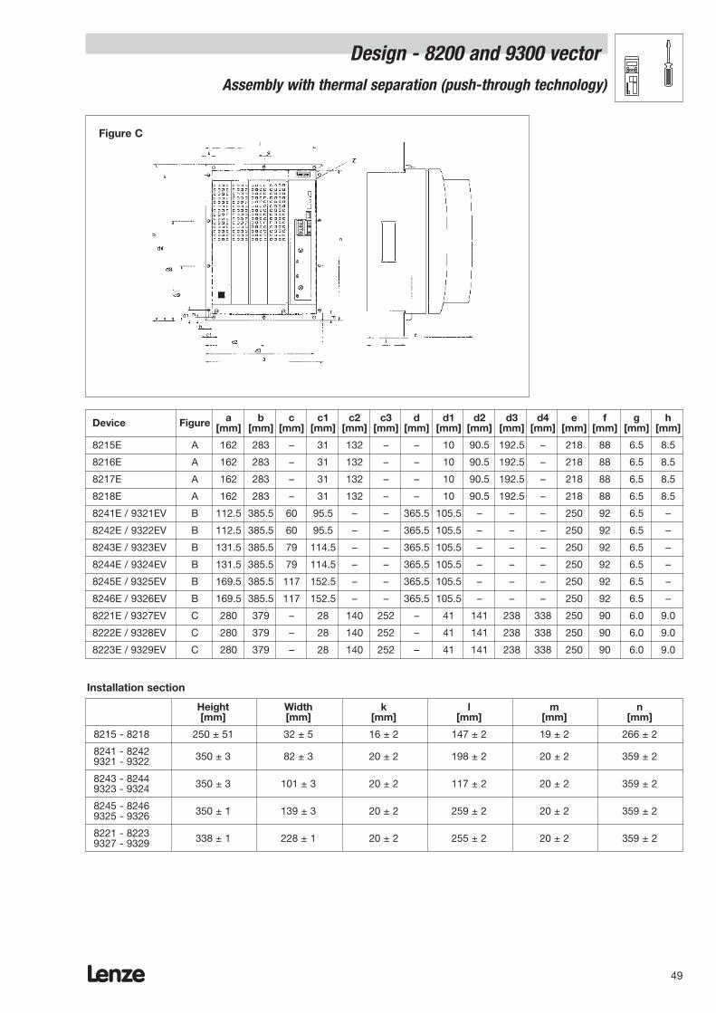
Height Width k l m n[mm] [mm] [mm] [mm] [mm] [mm]
8215 - 8218 250 ± 51 32 ± 5 16 ± 2 147 ± 2 19 ± 2 266 ± 2
8241 - 8242 350 ± 3 82 ± 3 20 ± 2 198 ± 2 20 ± 2 359 ± 29321 - 9322
8243 - 8244 350 ± 3 101 ± 3 20 ± 2 117 ± 2 20 ± 2 359 ± 29323 - 9324
8245 - 8246 350 ± 1 139 ± 3 20 ± 2 259 ± 2 20 ± 2 359 ± 29325 - 9326
8221 - 8223 338 ± 1 228 ± 1 20 ± 2 255 ± 2 20 ± 2 359 ± 29327 - 9329
Installation section
Figure C
Device Figure a b c c1 c2 c3 d d1 d2 d3 d4 e f g h[mm] [mm] [mm] [mm] [mm] [mm] [mm] [mm] [mm] [mm] [mm] [mm] [mm] [mm] [mm]
8215E A 162 283 – 31 132 – – 10 90.5 192.5 – 218 88 6.5 8.5
8216E A 162 283 – 31 132 – – 10 90.5 192.5 – 218 88 6.5 8.5
8217E A 162 283 – 31 132 – – 10 90.5 192.5 – 218 88 6.5 8.5
8218E A 162 283 – 31 132 – – 10 90.5 192.5 – 218 88 6.5 8.5
8241E / 9321EV B 112.5 385.5 60 95.5 – – 365.5 105.5 – – – 250 92 6.5 –
8242E / 9322EV B 112.5 385.5 60 95.5 – – 365.5 105.5 – – – 250 92 6.5 –
8243E / 9323EV B 131.5 385.5 79 114.5 – – 365.5 105.5 – – – 250 92 6.5 –
8244E / 9324EV B 131.5 385.5 79 114.5 – – 365.5 105.5 – – – 250 92 6.5 –
8245E / 9325EV B 169.5 385.5 117 152.5 – – 365.5 105.5 – – – 250 92 6.5 –
8246E / 9326EV B 169.5 385.5 117 152.5 – – 365.5 105.5 – – – 250 92 6.5 –
8221E / 9327EV C 280 379 – 28 140 252 – 41 141 238 338 250 90 6.0 9.0
8222E / 9328EV C 280 379 – 28 140 252 – 41 141 238 338 250 90 6.0 9.0
8223E / 9329EV C 280 379 – 28 140 252 – 41 141 238 338 250 90 6.0 9.0
Lenze50
Design - 8200 and 9300 vectorAssembly with other types of fixing
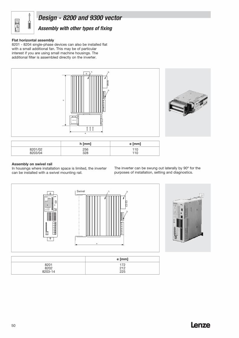
Flat horizontal assembly8201 - 8204 single-phase devices can also be installed flatwith a small additional fan. This may be of particularinterest if you are using small machine housings. Theadditional filter is assembled directly on the inverter.
1)
2)
3)
1 x 220V
Lüftermotor
e
h
Typ
Id.-
NR
Fert
.-N
rS
erie
n-N
r.E
inga
ng1
Ein
gang
2
LenzePostfach 101352 ,31763 HAMELN
e
1)
2)
3)Drehpunkt
Assembly on swivel railIn housings where installation space is limited, the invertercan be installed with a swivel mounting rail.
The inverter can be swung out laterally by 90º for thepurposes of installation, setting and diagnostics.
h [mm] e [mm]
8201/02 256 1108203/04 328 110
e [mm]
8201 1728202 212
8203-14 225
Swivel
Device Rated current Device Rated currentProtection device Protection device
8201 10 A 8203 20 A
8202 15 (16) A 8204 20 A
8211 / 8241 / 8242 / 9321 / 9322EV 6 A 8221 / 9327EV 50 A
8212 / 8243 / 9323EV 10 A 8222 / 9328EV 63 A
8213 10 A 8223 / 9329EV 80 A
8214 / 8244 / 9324EV 10 A 8224 / 9330EV 100 A
8215 16 (13) A 8225 / 9331EV 125 A
8216 / 8245 / 9325EV 20 A 8226 / 9332EV 160 A
8217 25 A 8227 / 9333EV 200 A
8218 / 8246 / 9326EV 32 A
( ) Automatic circuit breakersThe values provided are valid for operation with mains choke/mains filter
Lenze 51
Design - 8200 and 9300 vector Overview of cable protection
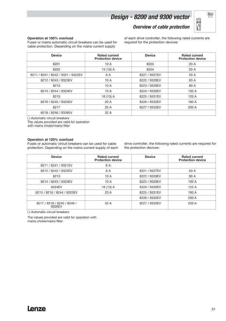
Operation at 150% overloadFuses or mains automatic circuit breakers can be used forcable protection. Depending on the mains current supply
of each drive controller, the following rated currents arerequired for the protection devices:
Operation at 120% overloadFuses or automatic circuit breakers can be used for cableprotection. Depending on the mains current supply of each
drive controller, the following rated currents are required forthe protection devices:
Device Rated current Device Rated currentProtection device Protection device
8211 / 8241 / 9321EV 6 A
8212 / 8242 / 9322EV 6 A 8221 / 9327EV 63 A
8213 10 A 8222 / 9328EV 80 A
8214 / 8243 / 9323EV 10 A 8223 / 9329EV 100 A
9324EV 16 (13) A 8224 / 9330EV 125 A
8215 / 8216 / 8244 / 9325EV 20 A 8225 / 9331EV 160 A
8226 / 9332EV 200 A
8217 / 8218 / 8245 / 8246 / 32 A 8227 / 9333EV 250 A9326EV
( ) Automatic circuit breakers
The values provided are valid for operation withmains choke/mains filter
Fuse Fuse holder
Device Rated Size Order ref. Required Order ref. Requiredcurrent number number
8201 M10A 6.3 x 32 EFSM-0100ASB 1 EFH30001 1
8202 M10A 6.3 x 32 EFSM-0100ASB 1 EFH30001 1
8203 M15A 6.3 x 32 EFSM-0150ASC 1 EFH30001 1
8204 M20A 6.3 x 32 EFSM-0200ASC 1 EFH30001 1
8211 / 8241 / 8242 M 6A 10 x 38 EFSM-0060AWE 3 EFH10001 39321 / 9322
8212 / 8243 / 9323EV M10A 10 x 38 EFSM-0100AWE 3 EFH10001 3
8213 M10A 10 x 38 EFSM-0100AWE 3 EFH10001 3
8214 / 8244 / 9324EV M10A 10 x 38 EFSM-0100AWE 3 EFH10001 3
8215 M16A 10 x 38 EFSM-0160AWE 3 EFH10001 3
8216 / 8245 / 9325EV M20A 10 x 38 EFSM-0200AWE 3 EFH10001 3
8217 M25A 14 x 51 EFSM-0250AXH 3 EFH10002 3
8218 / 8246 / 9326EV M32A 14 x 51 EFSM-0320AWH 3 EFH10002 3
8221*/9327EV* T50A – – 3 – –
8222* / 9328EV* T63A – – 3 – –
8223* / 9329EV* T80A – – 3 – –
8224* / 9330EV* T100A – – 3 – –
8225* / 9331EV* T125A – – 3 – –
8226* / 9332EV* T160A – – 3 – –
8227* / 9333EV* T200A – – 3 – –
* Recommended for standard fuses
Type a [mm] b [mm] e [mm] Fuse dimensions
EFH10001 17,5 81 68 10 x 38
EFH10002 26 81 68 14 x 51
EFH30001** 15 63 52 6.3 x 32
** Fixing: Bolt-on
Lenze52
Design - 8200 and 9300 vector Overview of line protection fuses
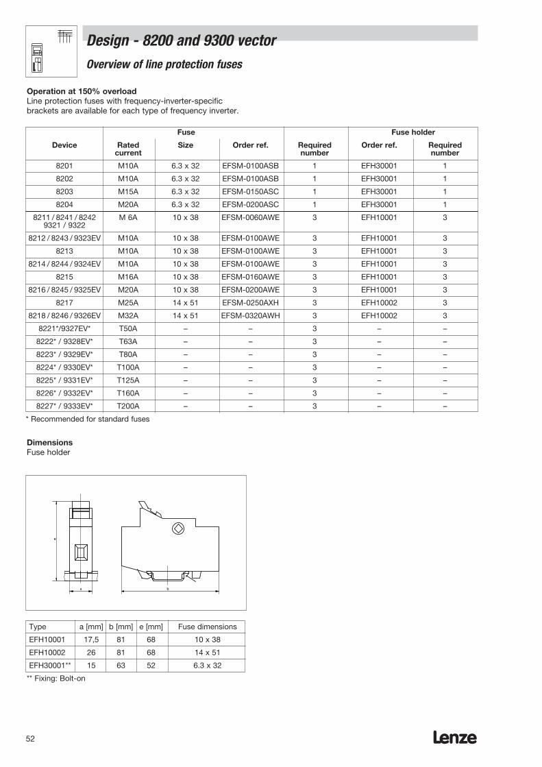
Operation at 150% overloadLine protection fuses with frequency-inverter-specificbrackets are available for each type of frequency inverter.
Dimensions Fuse holder
a b
e

Type a [mm] b [mm] e [mm] Fuse dimensions
EFH10001 17.5 81 68 10 x 38
EFH10002 26 81 68 14 x 51
Lenze 53
Operation at 120% overloadLine protection fuses with frequency-inverter-specificbrackets are available for each type of frequency inverter.
Fuse Fuse holder
Device Rated Size Order ref. Required Order ref. Requiredcurrent number number
8211 / 8241 / 9321EV M 6A 10 x 38 EFSM-0060AWE 3 EFH10001 3
8212 / 8242 / 9322EV M 6A 10 x 38 EFSM-0060AWE 3 EFH10001 3
8213 / 8214 / 8243 / M10A 10 x 38 EFSM-0100AWE 3 EFH10001 39323EV
8244 / 9324EV M16A 10 x 38 EFSM-0160AWE 3 EFH10001 3
8215 / 8216 / 9325EV M20A 10 x 38 EFSM-0200AWE 3 EFH10001 3
8217 / 82188245 / 8246 M32A 14 x 51 EFSM-0320AWH 3 EFH10002 3
9326EV
8221*/9327EV* T63A – – 3 – –
8222* / 9328EV* T80A – – 3 – –
8223* / 9329EV* T100A – – 3 – –
8224* / 9330EV* T125A – – 3 – –
8225* / 9331EV* T160A – – 3 – –
8226* / 9332EV* T200A – – 3 – –
8227* / 9333EV* T250A – – 3 – –
* Recommended for standard fuses
Dimensions Fuse holder
a b
e
Design - 8200 and 9300 vector Overview of line protection fuses
Lenze54
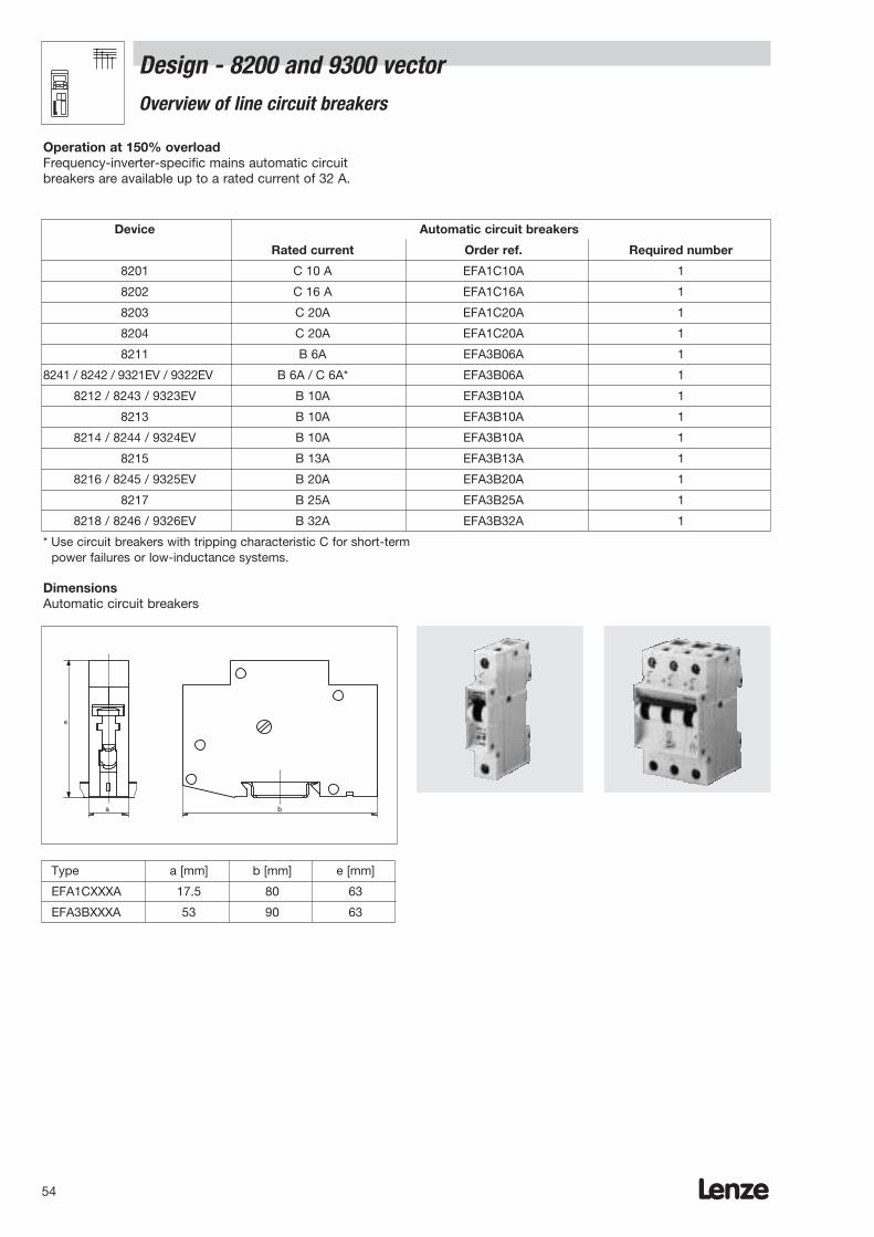
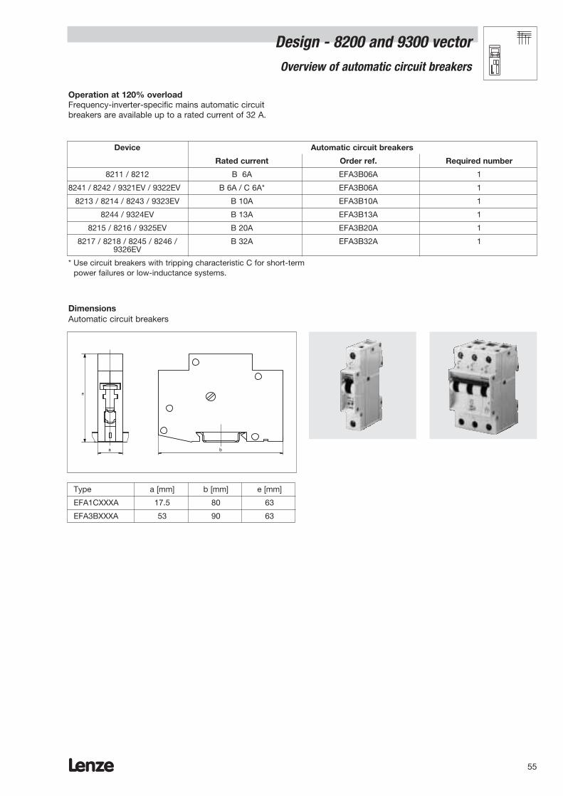
Operation at 150% overloadFrequency-inverter-specific mains automatic circuitbreakers are available up to a rated current of 32 A.
Device Automatic circuit breakers
Rated current Order ref. Required number
8201 C 10 A EFA1C10A 1
8202 C 16 A EFA1C16A 1
8203 C 20A EFA1C20A 1
8204 C 20A EFA1C20A 1
8211 B 6A EFA3B06A 1
8241 / 8242 / 9321EV / 9322EV B 6A / C 6A* EFA3B06A 1
8212 / 8243 / 9323EV B 10A EFA3B10A 1
8213 B 10A EFA3B10A 1
8214 / 8244 / 9324EV B 10A EFA3B10A 1
8215 B 13A EFA3B13A 1
8216 / 8245 / 9325EV B 20A EFA3B20A 1
8217 B 25A EFA3B25A 1
8218 / 8246 / 9326EV B 32A EFA3B32A 1
* Use circuit breakers with tripping characteristic C for short-termpower failures or low-inductance systems.
DimensionsAutomatic circuit breakers
e
ba
Type a [mm] b [mm] e [mm]
EFA1CXXXA 17.5 80 63
EFA3BXXXA 53 90 63
Design - 8200 and 9300 vector Overview of line circuit breakers
Lenze 55
Design - 8200 and 9300 vector Overview of automatic circuit breakers
Operation at 120% overloadFrequency-inverter-specific mains automatic circuitbreakers are available up to a rated current of 32 A.
Device Automatic circuit breakers
Rated current Order ref. Required number
8211 / 8212 B 6A EFA3B06A 1
8241 / 8242 / 9321EV / 9322EV B 6A / C 6A* EFA3B06A 1
8213 / 8214 / 8243 / 9323EV B 10A EFA3B10A 1
8244 / 9324EV B 13A EFA3B13A 1
8215 / 8216 / 9325EV B 20A EFA3B20A 1
8217 / 8218 / 8245 / 8246 / B 32A EFA3B32A 19326EV
* Use circuit breakers with tripping characteristic C for short-termpower failures or low-inductance systems.
DimensionsAutomatic circuit breakers
e
ba
Type a [mm] b [mm] e [mm]
EFA1CXXXA 17.5 80 63
EFA3BXXXA 53 90 63
Lenze56
Design - 8200 and 9300 vectorCE-typical installation
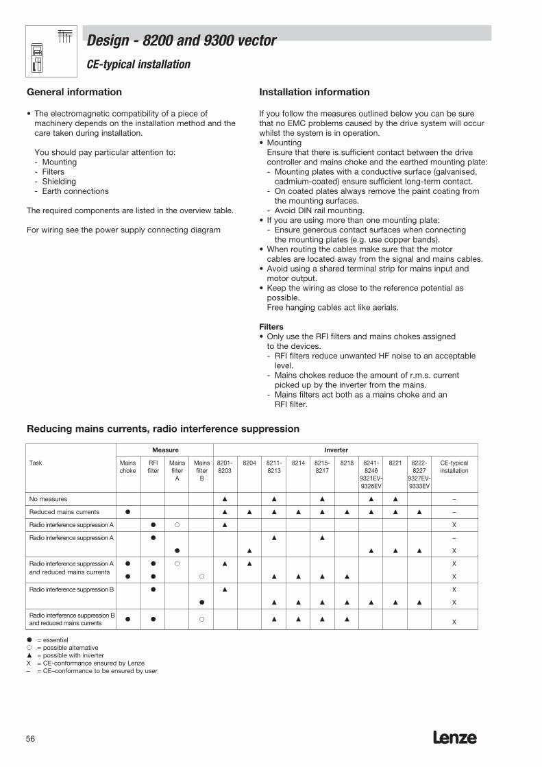
General information
• The electromagnetic compatibility of a piece ofmachinery depends on the installation method and thecare taken during installation.
You should pay particular attention to:- Mounting- Filters- Shielding- Earth connections
The required components are listed in the overview table.
For wiring see the power supply connecting diagram
Installation information
If you follow the measures outlined below you can be surethat no EMC problems caused by the drive system will occurwhilst the system is in operation.• Mounting
Ensure that there is sufficient contact between the drivecontroller and mains choke and the earthed mounting plate:- Mounting plates with a conductive surface (galvanised,
cadmium-coated) ensure sufficient long-term contact.- On coated plates always remove the paint coating from
the mounting surfaces.- Avoid DIN rail mounting.
• If you are using more than one mounting plate:- Ensure generous contact surfaces when connecting
the mounting plates (e.g. use copper bands).• When routing the cables make sure that the motor
cables are located away from the signal and mains cables.• Avoid using a shared terminal strip for mains input and
motor output.• Keep the wiring as close to the reference potential as
possible.Free hanging cables act like aerials.
Filters• Only use the RFI filters and mains chokes assigned
to the devices. - RFI filters reduce unwanted HF noise to an acceptable
level.- Mains chokes reduce the amount of r.m.s. current
picked up by the inverter from the mains.- Mains filters act both as a mains choke and an
RFI filter.
Measure Inverter
Task Mains RFI Mains Mains 8201- 8204 8211- 8214 8215- 8218 8241- 8221 8222- CE-typicalchoke filter filter filter 8203 8213 8217 8246 8227 installation
A B 9321EV- 9327EV-9326EV 9333EV
No measures –
Reduced mains currents –
Radio interference suppression A X
Radio interference suppression A –
X
Radio interference suppression A Xand reduced mains currents
X
Radio interference suppression B X
X
Radio interference suppression B Xand reduced mains currents
= essential = possible alternative = possible with inverterX = CE-conformance ensured by Lenze– = CE–conformance to be ensured by user
Reducing mains currents, radio interference suppression
Lenze 57
Design - 8200 and 9300 vector CE-typical installation
Shielding• Connect the motor cable shield with the drive controller
shield connection.• If contactors, motor protection switches or terminals
are located on the motor cable:- Connect the shields of the cables connected there
and ensure sufficient contact with the mounting plate.• In the terminal box of the motor, connect the shield
with PE:- Metal screw connections for the cables at the motor
terminal box ensure sufficient contact between theshield and the housing of the motor.
• If the mains cable between the mains filter and thedrive controller is longer than 300 mm:- Shield the mains cable.- Connect the shield of the mains cable directly with
the drive controller and mains filter and ensure sufficient contact with the mounting plate.
• If you are using a brake chopper:- Connect the shield of the brake resistor cable directly
with the brake copper and brake resistor and ensure sufficient contact with the mounting plate.
- Connect the shield of the cable between the inverter and the brake chopper directly to the inverter and ensure sufficient contact between the brake chopper and the mounting plate.
• If you are operating the devices on a DC bus:- Shield the cables between the inverter (+UG/-UG) and
the star point of the DC bus.- Ensure that there is sufficient contact on both sides
between the shield and the mounting plate.
• Shield the control cables:- Shield both ends of the digital control cables.- Shield one end of the analog control cables.- Use the shortest route possible to connect the shields
of the control cables with the designated shieldconnectors on the drive controller.
• If you are using the devices in residential areas:- Provide additional shield attenuation (= 10 dB) to limit
radiated interference. The usual way of doing this is toinstall the devices in standard enclosedmetallic and grounded control cabinets or boxes.
Ground connections• Use appropriate cables from a central grounding point
(PE rail) to ground all components (drive controller, mains filter, motor filter).
• You must observe the minimum cross sections definedin the safety regulations:- However, in terms of EMC it is not the cable cross
sectionbut the cable area and thecontact area which are of key importance, i.e.use the largest possible cross sections (large area).
Lenze58
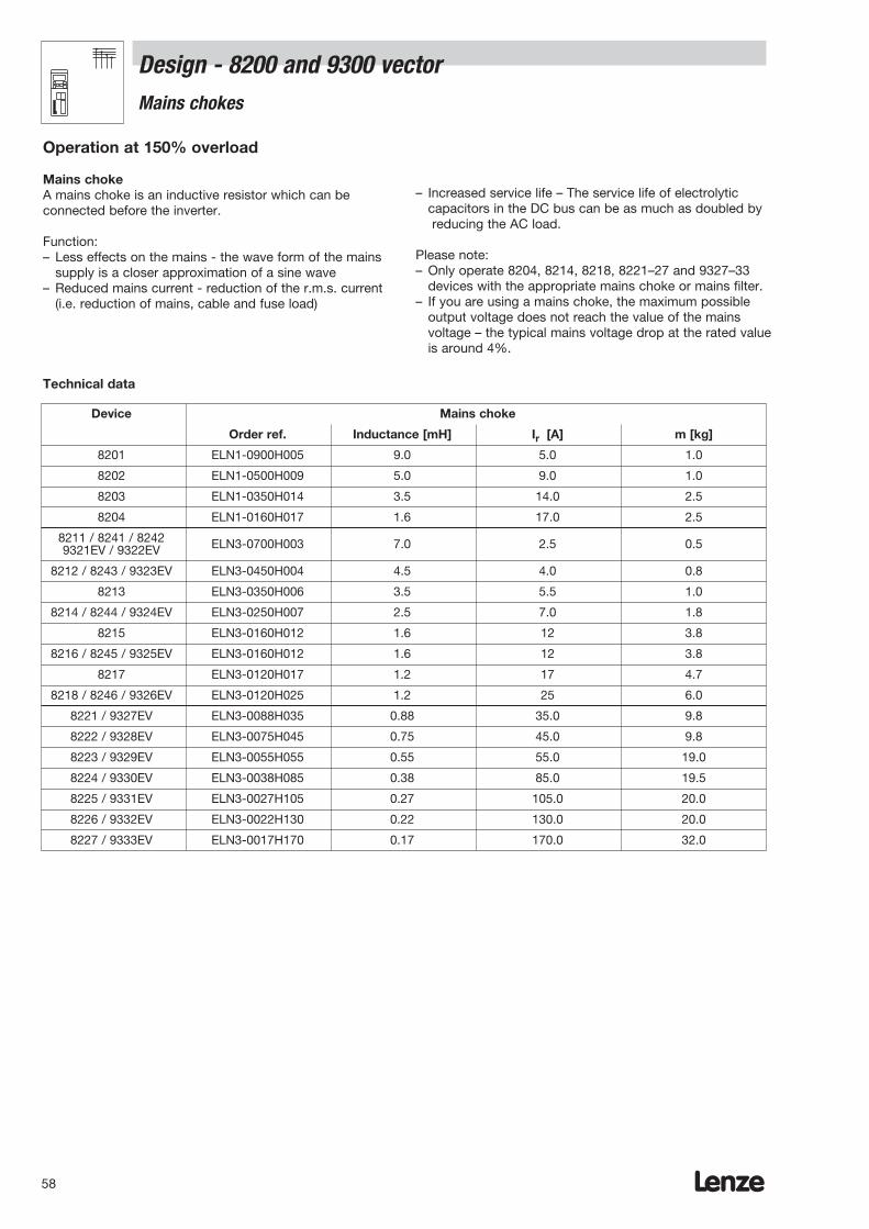
Design - 8200 and 9300 vector Mains chokes
Operation at 150% overload
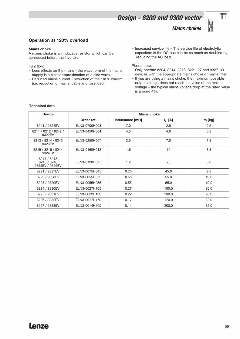
Mains chokeA mains choke is an inductive resistor which can beconnected before the inverter.
Function:– Less effects on the mains - the wave form of the mains
supply is a closer approximation of a sine wave– Reduced mains current - reduction of the r.m.s. current
(i.e. reduction of mains, cable and fuse load)
– Increased service life – The service life of electrolyticcapacitors in the DC bus can be as much as doubled byreducing the AC load.
Please note:– Only operate 8204, 8214, 8218, 8221–27 and 9327–33
devices with the appropriate mains choke or mains filter.– If you are using a mains choke, the maximum possible
output voltage does not reach the value of the mainsvoltage – the typical mains voltage drop at the rated valueis around 4%.
Device Mains choke
Order ref. Inductance [mH] Ir [A] m [kg]
8201 ELN1-0900H005 9.0 5.0 1.0
8202 ELN1-0500H009 5.0 9.0 1.0
8203 ELN1-0350H014 3.5 14.0 2.5
8204 ELN1-0160H017 1.6 17.0 2.5
8211 / 8241 / 8242 ELN3-0700H003 7.0 2.5 0.59321EV / 9322EV
8212 / 8243 / 9323EV ELN3-0450H004 4.5 4.0 0.8
8213 ELN3-0350H006 3.5 5.5 1.0
8214 / 8244 / 9324EV ELN3-0250H007 2.5 7.0 1.8
8215 ELN3-0160H012 1.6 12 3.8
8216 / 8245 / 9325EV ELN3-0160H012 1.6 12 3.8
8217 ELN3-0120H017 1.2 17 4.7
8218 / 8246 / 9326EV ELN3-0120H025 1.2 25 6.0
8221 / 9327EV ELN3-0088H035 0.88 35.0 9.8
8222 / 9328EV ELN3-0075H045 0.75 45.0 9.8
8223 / 9329EV ELN3-0055H055 0.55 55.0 19.0
8224 / 9330EV ELN3-0038H085 0.38 85.0 19.5
8225 / 9331EV ELN3-0027H105 0.27 105.0 20.0
8226 / 9332EV ELN3-0022H130 0.22 130.0 20.0
8227 / 9333EV ELN3-0017H170 0.17 170.0 32.0
Technical data
Lenze 59
Operation at 120% overload
Mains chokeA mains choke is an inductive resistor which can beconnected before the inverter.
Function:– Less effects on the mains - the wave form of the mains
supply is a closer approximation of a sine wave.– Reduced mains current - reduction of the r.m.s. current
(i.e. reduction of mains, cable and fuse load)
– Increased service life – The service life of electrolyticcapacitors in the DC bus can be as much as doubled byreducing the AC load.
Please note:– Only operate 8204, 8214, 8218, 8221–27 and 9327–33
devices with the appropriate mains choke or mains filter.– If you are using a mains choke, the maximum possible
output voltage does not reach the value of the mainsvoltage – the typical mains voltage drop at the rated valueis around 4%.
Device Mains choke
Order ref. Inductance [mH] Ir [A] m [kg]
8241 / 9321EV ELN3-0700H003 7.0 2.5 0.5
8211 / 8212 / 8242 / ELN3-0450H004 4.5 4.0 0.89322EV
8213 / 8214 / 8243 ELN3-0250H007 2.5 7.0 1.89323EV
8215 / 8216 / 8244 ELN3-0160H012 1.6 12 3.89324EV
8217 / 82188245 / 8246 ELN3-0120H025 1.2 25 6.0
9325EV / 9326EV
8221 / 9327EV ELN3-0075H045 0.75 45.0 9.8
8222 / 9328EV ELN3-0055H055 0.55 55.0 19.0
8223 / 9329EV ELN3-0055H055 0.55 55.0 19.0
8224 / 9330EV ELN3-0027H105 0.27 105.0 20.0
8225 / 9331EV ELN3-0022H130 0.22 130.0 20.0
8226 / 9332EV ELN3-0017H170 0.17 170.0 32.0
8227 / 9333EV ELN3-0014H200 0.14 200.0 32.0
Technical data
Design - 8200 and 9300 vectorMains chokes
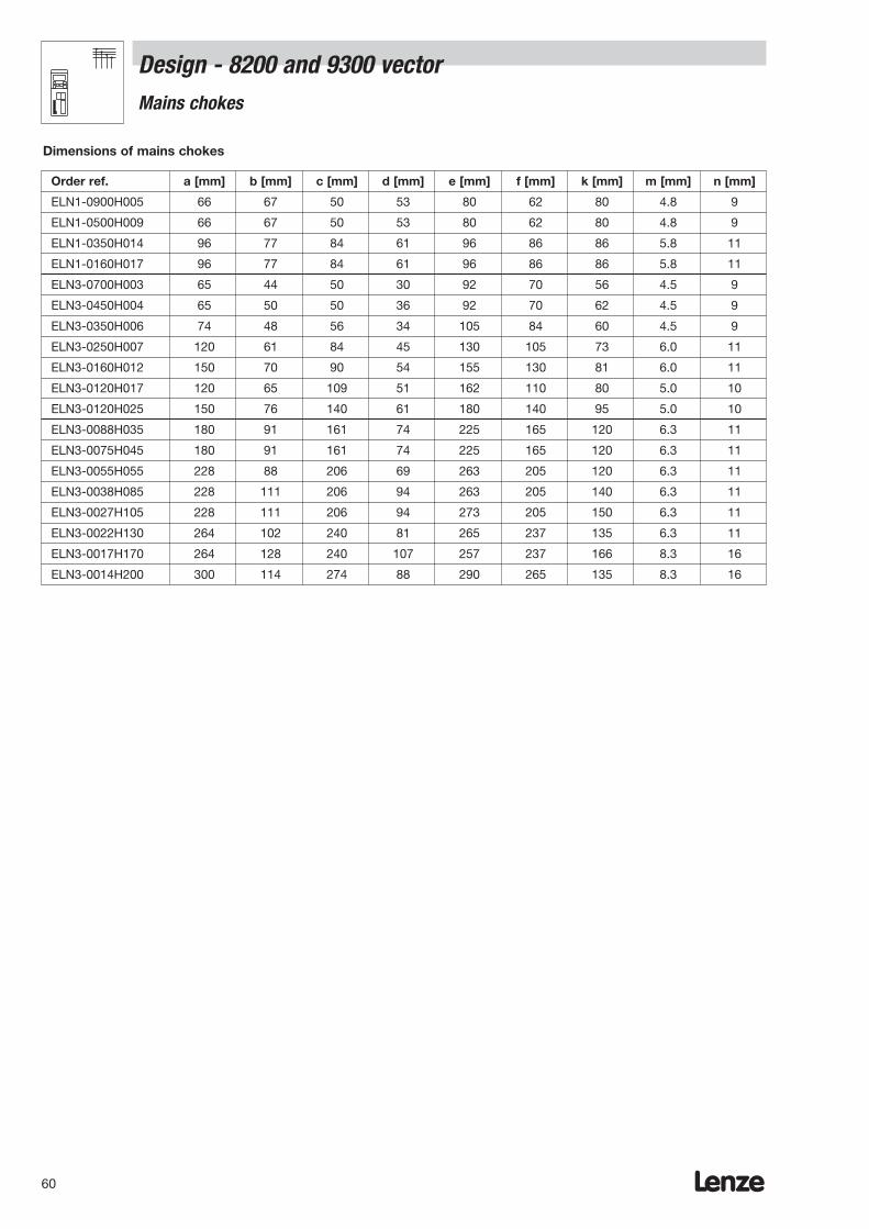
Lenze60
Dimensions of mains chokes
Order ref. a [mm] b [mm] c [mm] d [mm] e [mm] f [mm] k [mm] m [mm] n [mm]
ELN1-0900H005 66 67 50 53 80 62 80 4.8 9
ELN1-0500H009 66 67 50 53 80 62 80 4.8 9
ELN1-0350H014 96 77 84 61 96 86 86 5.8 11
ELN1-0160H017 96 77 84 61 96 86 86 5.8 11
ELN3-0700H003 65 44 50 30 92 70 56 4.5 9
ELN3-0450H004 65 50 50 36 92 70 62 4.5 9
ELN3-0350H006 74 48 56 34 105 84 60 4.5 9
ELN3-0250H007 120 61 84 45 130 105 73 6.0 11
ELN3-0160H012 150 70 90 54 155 130 81 6.0 11
ELN3-0120H017 120 65 109 51 162 110 80 5.0 10
ELN3-0120H025 150 76 140 61 180 140 95 5.0 10
ELN3-0088H035 180 91 161 74 225 165 120 6.3 11
ELN3-0075H045 180 91 161 74 225 165 120 6.3 11
ELN3-0055H055 228 88 206 69 263 205 120 6.3 11
ELN3-0038H085 228 111 206 94 263 205 140 6.3 11
ELN3-0027H105 228 111 206 94 273 205 150 6.3 11
ELN3-0022H130 264 102 240 81 265 237 135 6.3 11
ELN3-0017H170 264 128 240 107 257 237 166 8.3 16
ELN3-0014H200 300 114 274 88 290 265 135 8.3 16
Design - 8200 and 9300 vector Mains chokes

Lenze 61
m
c
a
n
d
bf
e
k
f
mca
db
n
e
k
ELN1-...
ELN3-...
Design - 8200 and 9300 vector Mains chokes
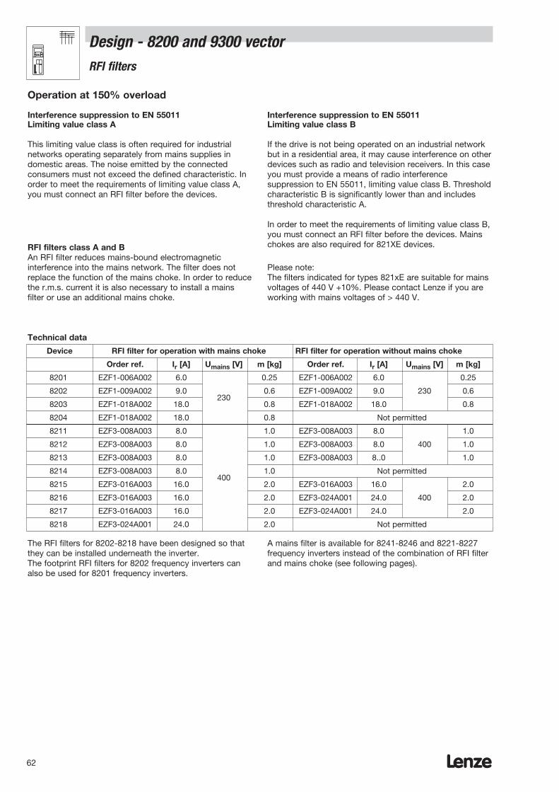
Lenze62
This limiting value class is often required for industrialnetworks operating separately from mains supplies indomestic areas. The noise emitted by the connectedconsumers must not exceed the defined characteristic. Inorder to meet the requirements of limiting value class A,you must connect an RFI filter before the devices.
RFI filters class A and BAn RFI filter reduces mains-bound electromagneticinterference into the mains network. The filter does notreplace the function of the mains choke. In order to reducethe r.m.s. current it is also necessary to install a mainsfilter or use an additional mains choke.
Operation at 150% overload
Interference suppression to EN 55011Limiting value class A
Interference suppression to EN 55011Limiting value class B
Technical data
Device RFI filter for operation with mains choke RFI filter for operation without mains choke
Order ref. Ir [A] Umains [V] m [kg] Order ref. Ir [A] Umains [V] m [kg]
8201 EZF1-006A002 6.0 0.25 EZF1-006A002 6.0 0.25
8202 EZF1-009A002 9.0230
0.6 EZF1-009A002 9.0 230 0.6
8203 EZF1-018A002 18.0 0.8 EZF1-018A002 18.0 0.8
8204 EZF1-018A002 18.0 0.8 Not permitted
8211 EZF3-008A003 8.0 1.0 EZF3-008A003 8.0 1.0
8212 EZF3-008A003 8.0 1.0 EZF3-008A003 8.0 400 1.0
8213 EZF3-008A003 8.0 1.0 EZF3-008A003 8..0 1.0
8214 EZF3-008A003 8.0400
1.0 Not permitted
8215 EZF3-016A003 16.0 2.0 EZF3-016A003 16.0 2.0
8216 EZF3-016A003 16.0 2.0 EZF3-024A001 24.0 400 2.0
8217 EZF3-016A003 16.0 2.0 EZF3-024A001 24.0 2.0
8218 EZF3-024A001 24.0 2.0 Not permitted
If the drive is not being operated on an industrial networkbut in a residential area, it may cause interference on otherdevices such as radio and television receivers. In this caseyou must provide a means of radio interferencesuppression to EN 55011, limiting value class B. Thresholdcharacteristic B is significantly lower than and includesthreshold characteristic A.
In order to meet the requirements of limiting value class B,you must connect an RFI filter before the devices. Mainschokes are also required for 821XE devices.
Please note:The filters indicated for types 821xE are suitable for mainsvoltages of 440 V +10%. Please contact Lenze if you areworking with mains voltages of > 440 V.
The RFI filters for 8202-8218 have been designed so thatthey can be installed underneath the inverter.The footprint RFI filters for 8202 frequency inverters canalso be used for 8201 frequency inverters.
A mains filter is available for 8241-8246 and 8221-8227frequency inverters instead of the combination of RFI filterand mains choke (see following pages).
Design - 8200 and 9300 vector RFI filters
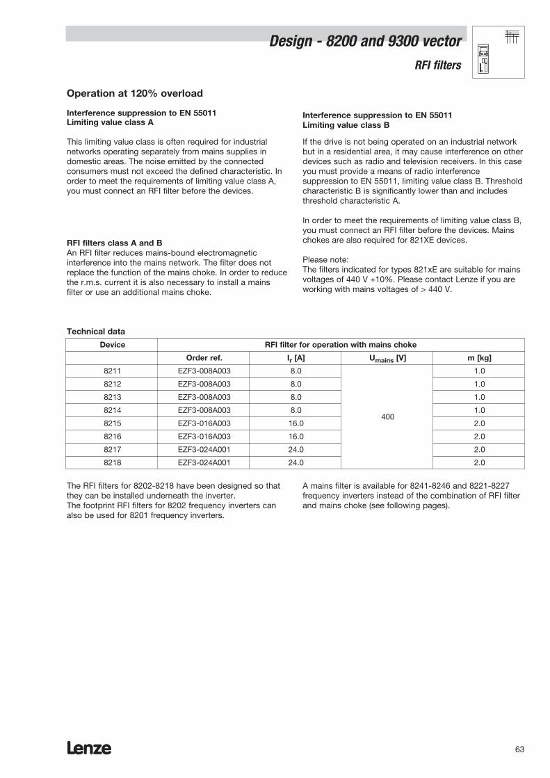
Lenze 63
Design - 8200 and 9300 vectorRFI filters
This limiting value class is often required for industrialnetworks operating separately from mains supplies indomestic areas. The noise emitted by the connectedconsumers must not exceed the defined characteristic. Inorder to meet the requirements of limiting value class A,you must connect an RFI filter before the devices.
RFI filters class A and BAn RFI filter reduces mains-bound electromagneticinterference into the mains network. The filter does notreplace the function of the mains choke. In order to reducethe r.m.s. current it is also necessary to install a mainsfilter or use an additional mains choke.
Operation at 120% overload
Interference suppression to EN 55011 Limiting value class A
Interference suppression to EN 55011 Limiting value class B
Technical data
Device RFI filter for operation with mains choke
Order ref. Ir [A] Umains [V] m [kg]
8211 EZF3-008A003 8.0 1.0
8212 EZF3-008A003 8.0 1.0
8213 EZF3-008A003 8.0 1.0
8214 EZF3-008A003 8.0400
1.0
8215 EZF3-016A003 16.0 2.0
8216 EZF3-016A003 16.0 2.0
8217 EZF3-024A001 24.0 2.0
8218 EZF3-024A001 24.0 2.0
If the drive is not being operated on an industrial networkbut in a residential area, it may cause interference on otherdevices such as radio and television receivers. In this caseyou must provide a means of radio interferencesuppression to EN 55011, limiting value class B. Thresholdcharacteristic B is significantly lower than and includesthreshold characteristic A.
In order to meet the requirements of limiting value class B,you must connect an RFI filter before the devices. Mainschokes are also required for 821XE devices.
Please note:The filters indicated for types 821xE are suitable for mainsvoltages of 440 V +10%. Please contact Lenze if you areworking with mains voltages of > 440 V.
The RFI filters for 8202-8218 have been designed so thatthey can be installed underneath the inverter.The footprint RFI filters for 8202 frequency inverters canalso be used for 8201 frequency inverters.
A mains filter is available for 8241-8246 and 8221-8227frequency inverters instead of the combination of RFI filterand mains choke (see following pages).

Lenze64
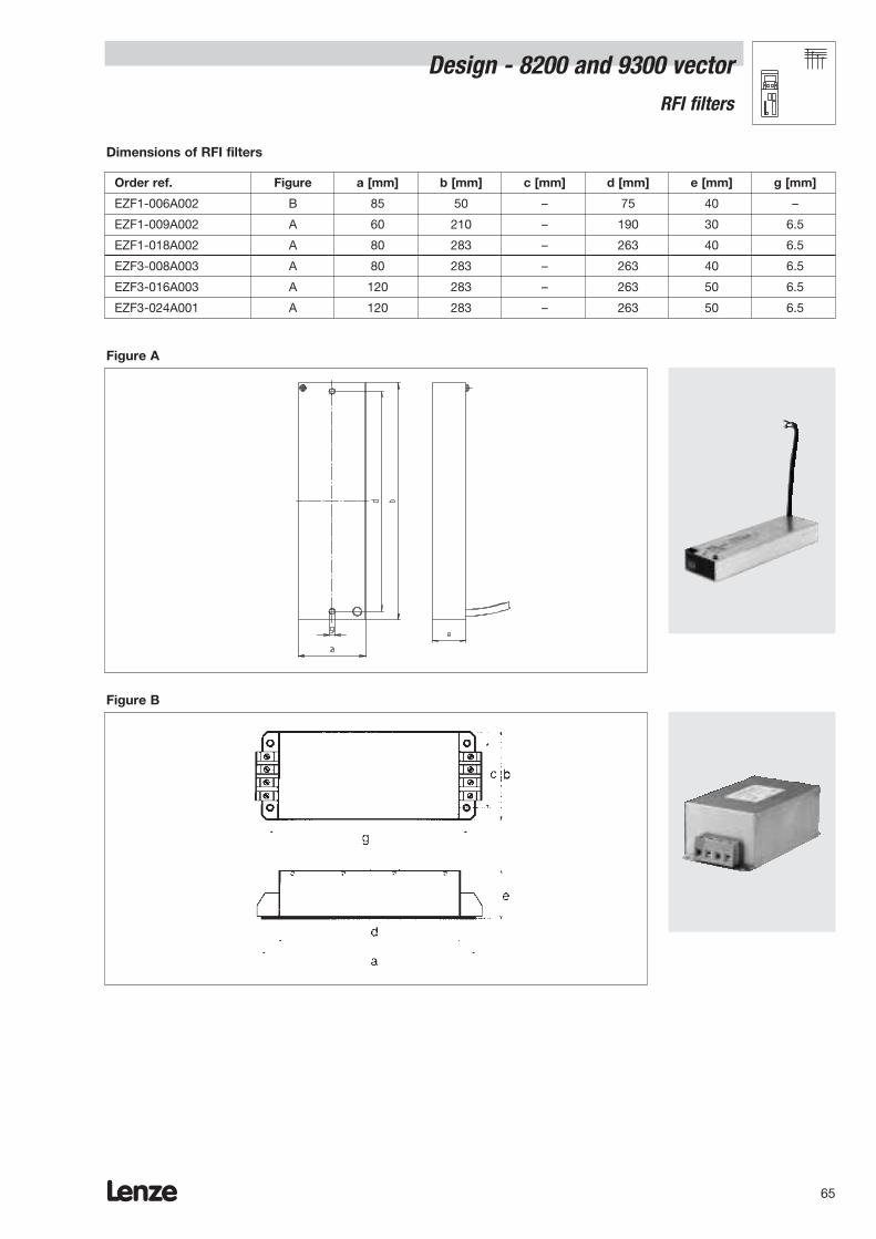
Lenze 65
Dimensions of RFI filters
Order ref. Figure a [mm] b [mm] c [mm] d [mm] e [mm] g [mm]
EZF1-006A002 B 85 50 – 75 40 –
EZF1-009A002 A 60 210 – 190 30 6.5
EZF1-018A002 A 80 283 – 263 40 6.5
EZF3-008A003 A 80 283 – 263 40 6.5
EZF3-016A003 A 120 283 – 263 50 6.5
EZF3-024A001 A 120 283 – 263 50 6.5
Figure A
Figure B
Design - 8200 and 9300 vectorRFI filters
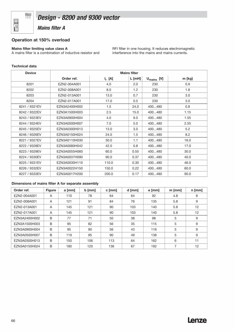
Design - 8200 and 9300 vectorMains filter A
Dimensions of mains filter A for separate assembly
Order ref. Figure a [mm] b [mm] c [mm] d [mm] e [mm] m [mm] n [mm]
EZN2-004A001 A 110 78 64 64 92 4.8 8
EZN2-008A001 A 121 91 84 76 135 5.8 9
EZN2-013A001 A 145 121 90 103 140 5.8 12
EZN2-017A001 A 145 121 90 103 140 5.8 12
EZN3A2400H002 B 77 71 50 38 98 5 9
EZN3A1500H003 B 95 82 56 35 115 5 9
EZN3A0900H004 B 95 90 56 43 116 5 9
EZN3A0500H007 B 119 95 90 49 138 5 9
EZN3A0300H013 B 150 106 113 64 162 6 11
EZN3A0150H024 B 180 120 136 67 192 7 12
Operation at 150% overload
Mains filter limiting value class A A mains filter is a combination of inductive resistor and
RFI filter in one housing. It reduces electromagneticinterference into the mains and mains currents.
Device Mains filter
Order ref. Ir [A] L [mH] Umains [V] m [kg]
8201 EZN2-004A001 4.0 2.0 230 0.9
8202 EZN2-008A001 8.0 1.2 230 1.8
8203 EZN2-013A001 13.0 0.7 230 3.0
8204 EZN2-017A001 17.0 0.5 230 3.0
8241 / 9321EV EZN3A2400H002 1.5 24.0 400...480 0.8
8242 / 9322EV EZN3A1500H003 2.5 15.0 400...480 1.15
8243 / 9323EV EZN3A0900H004 4.0 9.0 400...480 1.55
8244 / 9324EV EZN3A0500H007 7.0 5.0 400...480 2.55
8245 / 9325EV EZN3A0300H013 13.0 3.0 400...480 5.2
8246 / 9326EV EZN3A0150H024 24.0 1.5 400...480 8.2
8221 / 9327EV EZN3A0110H030 30.0 1.1 400...480 16.0
8222 / 9328EV EZN3A0080H042 42.0 0.8 400...480 17.0
8223 / 9329EV EZN3A0055H060 60.0 0.55 400...480 30.0
8224 / 9330EV EZN3A0037H090 90.0 0.37 400...480 40.0
8225 / 9331EV EZN3A0030H110 110.0 0.30 400...480 46.0
8226 / 9332EV EZN3A0022H150 150.0 0.22 400...480 60.0
8227 / 9333EV EZN3A0017H200 200.0 0.17 400...480 90.0
Technical data
Lenze66

Lenze 67
Operation at 120% overload
Mains filter limiting value class AA mains filter is a combination of inductive resistor and
RFI filter in one housing. It reduces electromagneticinterference into the mains and mains currents.
Dimensions of mains filter A for separate assembly
Order ref. Figure a [mm] b [mm] c [mm] d [mm] e [mm] m [mm] n [mm]
EZN3A2400H002 B 77 71 50 38 98 5 9
EZN3A1500H003 B 95 82 56 35 115 5 9
EZN3A0750H005 B 100 53 90 39 135 5 9
EZN3A0400H009 B 125 67 113 49 156 6 11
EZN3A0300H013 B 150 106 113 64 162 6 11
Device Mains filter
Order ref. Ir [A] L [mH] Umains [V] m [kg]
8241 / 9321EV EZN3A2400H002 1.5 24.0 400...480 0.8
8242 / 9322EV EZN3A1500H003 2.5 15.0 400...480 11.5
8243 / 9323EV EZN3A0750H005 5.0 7.5 400...480
8244 / 9324EV EZN3A0400H009 9.0 4.0 400...480
8245 / 9325EV EZN3A0300H013 13.0 3.0 400...480 5.2
8246 / 9326EV EZN3A0150H024 24.0 1.5 400...480
8221 / 9327EV EZN3A0080H042 42.0 0.8 400...480 15.0
8222 / 9328EV EZN3A0060H054 60.0 0.55 400...480 22.0
8223 / 9329EV EZN3A0055H060 60.0 0.55 400...480 30.0
8224 / 8225 EZN3A0030H110 110.0 0.30 400...480 45.09330 / 9331EV
8226 / 9332EV EZN3A0022H150 150.0 0.22 400...480 60.0
8227 / 9333EV EZN3A0017H200 200.0 0.17 400...480 90.0
Technical data
Design - 8200 and 9300 vector Mains filter A
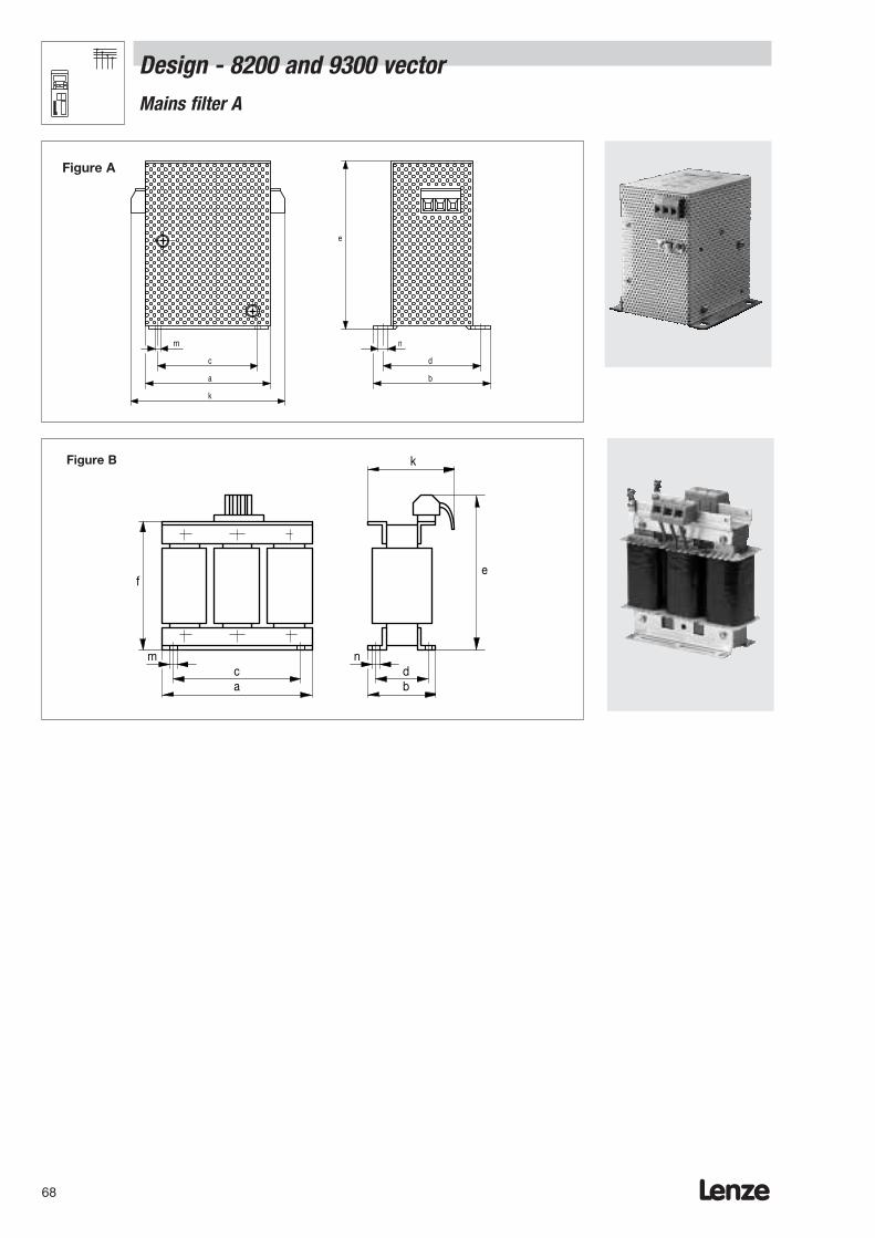
Lenze68
Design - 8200 and 9300 vectorMains filter A
c
a
m n
e
d
b
k
Figure A
Figure B
f
mca
db
n
e
k

Lenze 69
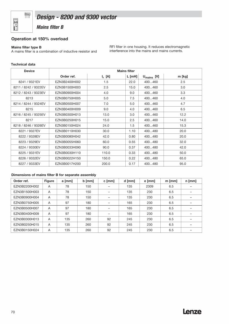
Lenze70
Design - 8200 and 9300 vector Mains filter B
Order ref. Figure a [mm] b [mm] c [mm] d [mm] e [mm] m [mm] n [mm]
EZN3B2200H002 A 78 150 – 135 2309 6.5 –
EZN3B1500H003 A 78 150 – 135 230 6.5 –
EZN3B0900H004 A 78 150 – 135 230 6.5 –
EZN3B0750H005 A 97 180 – 165 230 6.5 –
EZN3B0500H007 A 97 180 – 165 230 6.5 –
EZN3B0400H009 A 97 180 – 165 230 6.5 –
EZN3B0300H013 A 135 260 92 245 230 6.5 –
EZN3B0250H015 A 135 260 92 245 230 6.5 –
EZN3B0150H024 A 135 260 92 245 230 6.5 –
Dimensions of mains filter B for separate assembly
Operation at 150% overload
Mains filter type BA mains filter is a combination of inductive resistor and
RFI filter in one housing. It reduces electromagneticinterference into the mains and mains currents.
Device Mains filter
Order ref. Ir [A] L [mH] Umains [V] m [kg]
8241 / 9321EV EZN3B2400H002 1.5 22.0 400...460 2.5
8211 / 8242 / 9322EV EZN3B1500H003 2.5 15.0 400...460 3.0
8212 / 8243 / 9323EV EZN3B0900H004 4.0 9.0 400...460 3.3
8213 EZN3B0750H005 5.0 7.5 400...460 4.0
8214 / 8244 / 9324EV EZN3B0500H007 7.0 5.0 400...460 4.7
8215 EZN3B0400H009 9.0 4.0 400...460 6.5
8216 / 8245 / 9325EV EZN3B0300H013 13.0 3.0 400...460 12.2
8217 EZN3B0250H015 15.0 2.5 400...460 14.0
8218 / 8246 / 9326EV EZN3B0150H024 24.0 1.5 400...460 15.3
8221 / 9327EV EZN3B0110H030 30.0 1.10 400...480 20.0
8222 / 9328EV EZN3B0080H042 42.0 0.80 400...480 20.0
8223 / 9329EV EZN3B0055H060 60.0 0.55 400...480 32.0
8224 / 9330EV EZN3B0033H090 90.0 0.37 400...480 42.0
8225 / 9331EV EZN3B0030H110 110.0 0.33 400...480 50.0
8226 / 9332EV EZN3B0022H150 150.0 0.22 400...480 65.0
8227 / 9333EV EZN3B0017H200 200.0 0.17 400...480 95.0
Technical data
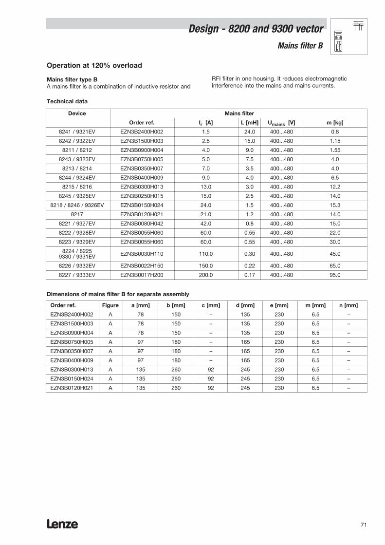
Lenze 71
Order ref. Figure a [mm] b [mm] c [mm] d [mm] e [mm] m [mm] n [mm]
EZN3B2400H002 A 78 150 – 135 230 6.5 –
EZN3B1500H003 A 78 150 – 135 230 6.5 –
EZN3B0900H004 A 78 150 – 135 230 6.5 –
EZN3B0750H005 A 97 180 – 165 230 6.5 –
EZN3B0350H007 A 97 180 – 165 230 6.5 –
EZN3B0400H009 A 97 180 – 165 230 6.5 –
EZN3B0300H013 A 135 260 92 245 230 6.5 –
EZN3B0150H024 A 135 260 92 245 230 6.5 –
EZN3B0120H021 A 135 260 92 245 230 6.5 –
Dimensions of mains filter B for separate assembly
Device Mains filter
Order ref. Ir [A] L [mH] Umains [V] m [kg]
8241 / 9321EV EZN3B2400H002 1.5 24.0 400...480 0.8
8242 / 9322EV EZN3B1500H003 2.5 15.0 400...480 1.15
8211 / 8212 EZN3B0900H004 4.0 9.0 400...480 1.55
8243 / 9323EV EZN3B0750H005 5.0 7.5 400...480 4.0
8213 / 8214 EZN3B0350H007 7.0 3.5 400...480 4.0
8244 / 9324EV EZN3B0400H009 9.0 4.0 400...480 6.5
8215 / 8216 EZN3B0300H013 13.0 3.0 400...480 12.2
8245 / 9325EV EZN3B0250H015 15.0 2.5 400...480 14.0
8218 / 8246 / 9326EV EZN3B0150H024 24.0 1.5 400...480 15.3
8217 EZN3B0120H021 21.0 1.2 400...480 14.0
8221 / 9327EV EZN3B0080H042 42.0 0.8 400...480 15.0
8222 / 9328EV EZN3B0055H060 60.0 0.55 400...480 22.0
8223 / 9329EV EZN3B0055H060 60.0 0.55 400...480 30.0
8224 / 8225 EZN3B0030H110 110.0 0.30 400...480 45.09330 / 9331EV
8226 / 9332EV EZN3B0022H150 150.0 0.22 400...480 65.0
8227 / 9333EV EZN3B0017H200 200.0 0.17 400...480 95.0
Technical data
Operation at 120% overload
Mains filter type BA mains filter is a combination of inductive resistor and
RFI filter in one housing. It reduces electromagneticinterference into the mains and mains currents.
Design - 8200 and 9300 vectorMains filter B
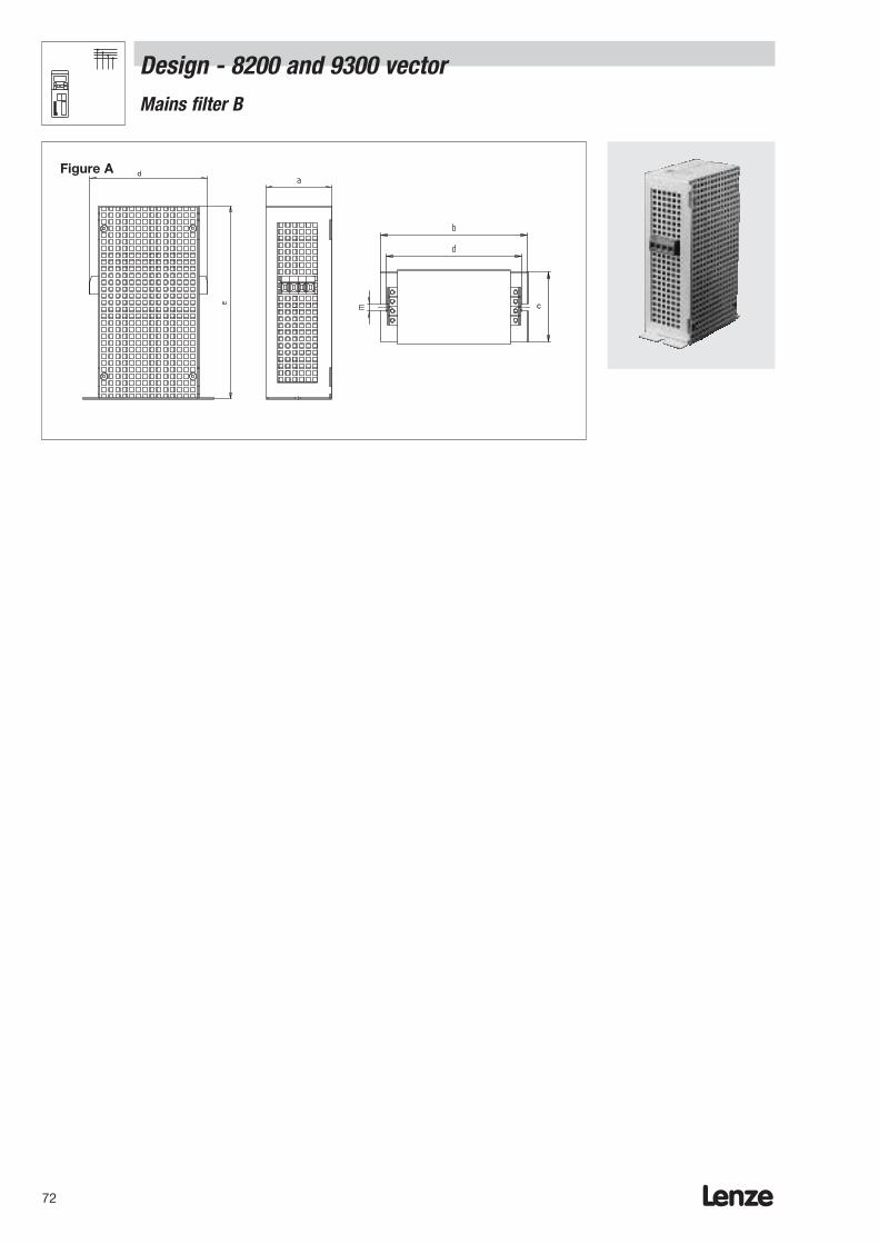
Lenze72
Design - 8200 and 9300 vectorMains filter B
dFigure A
c
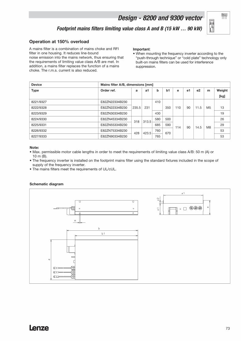
Lenze 73
Operation at 150% overload
Design - 8200 and 9300 vector Footprint mains filters limiting value class A and B (15 kW … 90 kW)
Device Mains filter A/B, dimensions [mm]
Type Order ref. a a1 b b1 e e1 e2 m Weight
[kg]
8221/9327 E82ZN22334B230 410
8222/9328 E82ZN22334B230 235.5 231 350 110 90 11.5 M5 13
8223/9329 E82ZN30334B230 430 19
8224/9330 E82ZN45334B230318 313.5
580 500 26
8225/9331 E82ZN55334B230 685 590114 90 14.5 M8
29
8226/9332 E82ZN75334B230428 423.5
760670
53
8227/9333 E82ZN90334B230 765 53
A mains filter is a combination of mains choke and RFIfilter in one housing. It reduces line-bound noise emission into the mains network, thus ensuring thatthe requirements of limiting value class A/B are met. Inaddition, a mains filter replaces the function of a mainschoke. The r.m.s. current is also reduced.
Important:• When mounting the frequency inverter according to the
“push-through technique” or “cold plate” technology onlybuilt-on mains filters can be used for interferencesuppression.
Note:• Max. permissible motor cable lengths in order to meet the requirements of limiting value class A/B: 50 m (A) or
10 m (B).• The frequency inverter is installed on the footprint mains filter using the standard fixtures included in the scope of
supply of the frequency inverter. • The mains filters meet the requirements of UL/cUL.
Schematic diagram

Lenze74
Operating at 120% overload
8200 and 9300 vector rangesSubassembly mains filter limiting value class A and B (15 kW ... 90 kW)
Device Mains filter A/B, dimensions [mm]
Type Order ref. a a1 b b1 e e1 e2 m Weight
[kg]
8221/9327 E82ZN22334B230 410 13
8222/9328 E82ZN30334B230235.5 231
430350 110 90 11.5 M5
19
8224/9330 E82ZN55334B230 318 313.5 685 590114 90 14.5 M8
29
8226/9332 E82ZN90334B230 428 423.5 765 670 53
A mains filter is a mains choke and RFI filter combined inone housing. It reduces line-bound noise emission into themains network, thus ensuring that limiting value class A/Bis satisfied. In addition, a mains filter performs the functionof a mains choke. This also means that the mains current’sr.m.s. value is reduced.
Important:• When mounting the frequency inverter using the
“push-through technique” or “cold plate” technology onlyintegrated mains filters can be used for interferencesuppression.
Note:• Max. permitted motor cable lengths in compliance with limiting value class A or B: 50 m (A) or 10 m (B).• The frequency inverter is installed on the subassembly mains filter using the standard fixtures included in the
frequency inverter’s scope of supply. • The mains filters meet the requirements of UL/cUL.
Schematic diagram
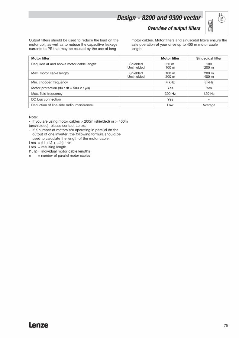
Lenze 75
Design - 8200 and 9300 vector M3~
Overview of output filters
Output filters should be used to reduce the load on themotor coil, as well as to reduce the capacitive leakagecurrents to PE that may be caused by the use of long
motor cables. Motor filters and sinusoidal filters ensure thesafe operation of your drive up to 400 m motor cablelength.
Motor filter Motor filter Sinusoidal filter
Required at and above motor cable length Shielded 50 m 100Unshielded 100 m 200 m
Max. motor cable length Shielded 100 m 200 mUnshielded 200 m 400 m
Min. chopper frequency 4 kHz 8 kHz
Motor protection (du / dt = 500 V / s) Yes Yes
Max. field frequency 300 Hz 120 Hz
DC bus connection Yes -
Reduction of line-side radio interference Low Average
Note:- If you are using motor cables > 200m (shielded) or > 400m (unshielded), please contact Lenze.- If a number of motors are operating in parallel on the
output of one inverter, the following formula should be used to calculate the length of the motor cable:
l res = (l1 + l2 + ...ln) * √n l res = resulting lengthl1, l2 = individual motor cable lengthsn = number of parallel motor cables

Lenze76
Design - 8200 and 9300 vectorMotor filter
M3~
A motor filter is required:– For long motor cables
> 50 m (shielded) or > 100 m (unshielded)– If motors are used with an insulation system not suited
for inverter operation. Lenze motors feature insulationwith a high thermal reserve.
Please note:– The frequency inverter is also loaded with approx. 12%
of the motor filter rated current.– Shielded motor cables are required for a CE-typical
installation
– The typical mains voltage drop via the motor filter at ratedcurrent and rated frequency is 2 -3% of the outputvoltage
– The filters indicated are suitable for a mains voltage of upto 3 x 460 V ± 10%
– The +UG and –UG terminals must be connected with thesame cable cross-section as the motor cable.
Device Motor filter
Order ref. Inductance [mH] Ir [A] Umains [V] m [kg]
8201 ELM3-030H003 3.0 2.5 3 x 230 4.0
8202 ELM3-020H004 2.0 4.0 3 x 230 4.0
8203 ELM3-010H010 1.0 10.0 3 x 230 7.0
8204 ELM3-014H010 1.4 10.0 3 x 230 7.0
8211/ 8241/ 8242 / 9321EV / 9322EV ELM3-030H004 3.0 4.0 3 x 460 4.0
8212 / 8243 / 9323EV ELM3-030H004 3.0 4.0 3 x 460 4.0
8213 ELM3-014H010 1.4 10.0 3 x 460 7.0
8214 / 8244 / 9324EV ELM3-014H010 1.4 10.0 3 x 460 7.0
8215 ELM3-014H010 1.4 10.0 3 x 460 7.0
8216 / 8245 / 9325EV ELM3-007H025 0.7 25.0 3 x 460 14.0
8217 ELM3-007H025 0.7 25.0 3 x 460 14.0
8218 / 8246 / 9326EV ELM3-007H025 0.7 25.0 3 x 460 14.0
8221-8222 / 9327-28EV ELM3-004H055 0.4 55.0 3 x 460 40.0
8223-8227 / 9329-33EV on request
Technical data for 150% overload
Device Motor filter
Order ref. Inductance [mH] Ir [A] Umains [V] m [kg]
8211 / 8241 / 9321EV ELM3-030H004 3.0 4.0 3 x 460 4.0
8212 / 8242 / 9322EV ELM3-030H004 3.0 4.0 3 x 460 4.0
8213 / 8214 / 8243 / 9323EV ELM3-014H010 1.4 10.0 3 x 460 7.0
8215 / 8216 / 8244 / 9324EV ELM3-007H025 0.7 25.0 3 x 460 14.0
8217 / 8245 / 9325EV ELM3-007H025 0.7 25.0 3 x 460 14.0
8218 / 8246 / 9326EV ELM3-007H025 0.7 25.0 3 x 460 14.0
8221 / 9327EV ELM3-004H055 0.4 55.0 3 x 460 40.0
8222-8227 / 9328EV-9333EV on request
Technical data for 120% overload

Lenze 77
c
e
b
d
a
Type a [mm] b [mm] c [mm] d [mm] e [mm]
ELM3-030H003 210 60 140 197 35
ELM3-020H004 210 60 140 197 35
ELM3-010H010 280 92 135 267 65
ELM3-030H004 210 75 160 197 50
ELM3-014H010 280 92 175 267 65
ELM3-007H025 280 130 256 267 100
ELM3-004H055 500 235 185 400 220
Dimensions of motor filters
Design - 8200 and 9300 vector Motor filters
M3~
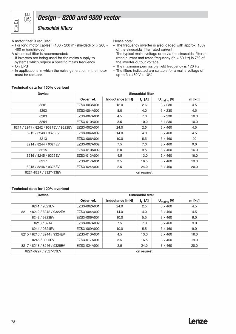
Lenze78
Design - 8200 and 9300 vector M3~
Sinusoidal filters
A motor filter is required:– For long motor cables > 100 - 200 m (shielded) or > 200 -
400 m (unshielded)A sinusoidal filter is recommended:– If inverters are being used for the mains supply to
systems which require a specific mains frequency– On UPS– In applications in which the noise generation in the motor
must be reduced
Please note:– The frequency inverter is also loaded with approx. 10%
of the sinusoidal filter rated current– The typical mains voltage drop via the sinusoidal filter at
rated current and rated frequency (fn = 50 Hz) is 7% ofthe inverter output voltage
– The maximum permissible field frequency is 120 Hz– The filters indicated are suitable for a mains voltage of
up to 3 x 460 V ± 10%
Device Sinusoidal filter
Order ref. Inductance [mH] Ir [A] Umains [V] m [kg]
8201 EZS3-003A001 12.0 2.6 3 x 230 4.5
8202 EZS3-004A002 8.0 4.0 3 x 230 4.5
8203 EZS3-007A001 4.5 7.0 3 x 230 10.0
8204 EZS3-010A001 3.5 10.0 3 x 230 10.0
8211 / 8241 / 8242 / 9321EV / 9322EV EZS3-002A001 24.0 2.5 3 x 460 4.5
8212 / 8243 / 9323EV EZS3-004A002 14.0 4.0 3 x 460 4.5
8213 EZS3-006A001 10.0 5.5 3 x 460 90
8214 / 8244 / 9324EV EZS3-007A002 7.5 7.0 3 x 460 9.0
8215 EZS3-010A002 6.0 9.5 3 x 460 16.0
8216 / 8245 / 9325EV EZS3-013A001 4.5 13.0 3 x 460 16.0
8217 EZS3-017A001 3.5 16.5 3 x 460 19.0
8218 / 8246 / 9326EV EZS3-024A001 2.5 24.0 3 x 460 20.0
8221-8227 / 9327-33EV on request
Technical data for 150% overload
Device Sinusoidal filter
Order ref. Inductance [mH] Ir [A] Umains [V] m [kg]
8241 / 9321EV EZS3-002A001 24.0 2.5 3 x 460 4.5
8211 / 8212 / 8242 / 9322EV EZS3-004A002 14.0 4.0 3 x 460 4.5
8243 / 9323EV EZS3-006A001 10.0 5.5 3 x 460 9.0
8213 / 8214 EZS3-007A002 7.5 7.0 3 x 460 9.0
8244 / 9324EV EZS3-009A002 10.0 5.5 3 x 460 9.0
8215 / 8216 / 8244 / 9324EV EZS3-013A001 4.5 13.0 3 x 460 16.0
8245 / 9325EV EZS3-017A001 3.5 16.5 3 x 460 19.0
8217 / 8218 / 8246 / 9326EV EZS3-024A001 2.5 24.0 3 x 460 20.0
8221-8227 / 9327-33EV on request
Technical data for 120% overload

Lenze 79
Design - 8200 and 9300 vector M3~
Sinusoidal filters
d
a
c
e
b
Dimensions of sinusoidal filters
a
d
g
b
c
e
Dimensions of sinusoidal filters
Order ref. a [mm] b [mm] c [mm] d [mm] e [mm]
EZS3-003A001 210 75 120 200 50
EZS3-004A002 210 75 120 200 50
EZS3-007A001 280 92 135 270 65
EZS3-010A001 280 92 135 270 65
EZS3-002A001 210 75 160 200 50
EZS3-004A002 210 75 160 200 50
EZS3-006A001 280 92 175 270 65
EZS3-007A002 280 92 175 270 65
EZS3-009A002 280 92 175 270 65
EZS3-010A002 280 130 256 267 100
EZS3-013A001 280 130 256 267 100
EZS3-017A001 280 130 256 267 100
EZS3-024A001 325 200 170 260 185
Larger filters are available on request

Lenze80
Design - 8200 and 9300 vectorn
t
Braking
Options
Braking with brake unitIf a motor is braked quickly by the frequency inverter, themotor will operate in generative mode and feed backenergy to the frequency inverter. The DC bus voltage ofthe frequency inverter increases. If the voltage is too high,the frequency inverter will lock the power stages and themotor will coast to a stop. By using a brake unitcomprising a brake module with integrated resistor orbrake chopper with external resistor, the feedback energycan be dissipated via the brake resistor and converted intoheat. The drive can be braked under controlled conditions.
Feedback modeA supply and feedback module can also be used as analternative, in particular on multi-axis and interconnecteddrives. These components help to reduce energyconsumption and costs.
Selecting brake resistorsBrake resistors are selected according to the continuousenergy loss exhibited and the energy to be braked. The following formula is used to calculate the rated powerof the brake resistors:
The maximum kinetic energy to be suppressed iscalculated on the basis of the peak brake power and themaximum duty time of the brake chopper.
Wmax = Pmax · t0max
Pmax: Brake power during braking
tBr: Braking time
tcyc: Time between two braking cycles
Wkin: Kinetic energy to be braked
t0max: Maximum duty time of brake chopper
As the frequency change is also applied in the brakingphase via the setpoint integrator on the inverter, the “Tif”value set on the inverter can also be used for the brakingtime tBr.
PN ≥tBr x Pmax ; Pmax =
1 Wkintzyk 2 tBr
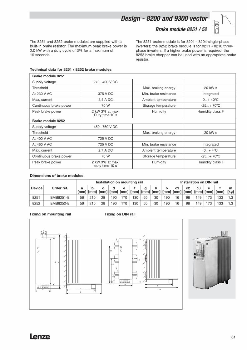
Lenze 81
Design - 8200 and 9300 vectorBrake module 8251 / 52
n
t
The 8251 and 8252 brake modules are supplied with abuilt-in brake resistor. The maximum peak brake power is2.0 kW with a duty cycle of 3% for a maximum of10 seconds.
The 8251 brake module is for 8201 - 8204 single-phaseinverters; the 8252 brake module is for 8211 - 8218 three-phase inverters. If a higher brake power is required, the 8253 brake chopper can be used with an appropriate brakeresistor.
Brake module 8251
Supply voltage 270...400 V DC
Threshold Max. braking energy 20 kW s
At 230 V AC 375 V DC Min. brake resistance Integrated
Max. current 5.4 A DC Ambient temperature 0...+ 40ºC
Continuous brake power 70 W Storage temperature -25...+ 70ºC
Peak brake power 2 kW 3% at max. Humidity Humidity class FDuty time 10 s
Brake module 8252
Supply voltage 450...750 V DC
Threshold Max. braking energy 20 kW s
At 400 V AC 725 V DC
At 460 V AC 725 V DC Min. brake resistance Integrated
Max. current 2.7 A DC Ambient temperature 0...+ 4ºC
Continuous brake power 70 W Storage temperature -25...+ 70ºC
Peak brake power 2 kW 3% at max. Humidity Humidity class Fduty time 10 s
Technical data for 8251 / 8252 brake modules
Dimensions of brake modules
Installation on mounting rail Installation on DIN rail
Device Order ref. a b c d e f g k b c1 c2 c3 e f m[mm] [mm] [mm] [mm] [mm] [mm] [mm] [mm] [mm] [mm] [mm] [mm] [mm] [mm] [kg]
8251 EMB8251-E 56 210 28 190 170 130 65 30 190 16 98 149 173 133 1.3
8252 EMB8252-E 56 210 28 190 170 130 65 30 190 16 98 149 173 133 1.3
Fixing on mounting rail Fixing on DIN rail
1)
1)
-UG +UG RB1 RB2 PE(T1) (T2)
a
e
b
c1
c2
c3
f-UG +UG RB1 RB2 PE (T1) (T2)
a e
b
f
d
gk

Lenze82
Design - 8200 and 9300 vectorBrake module 9351
n
t
The 9351 brake module is supplied with a built-in brakeresistor. This brake resistor has a resistance of 47 ohms.The maximum peak brake power is 12 kW at a threshold of765 V DC. At a pulse/break ratio of 1:250, the maximumduty time is 2 seconds. Depending on the brake powerrequired, the brake module can be used with all
8241-8246, 8221-27 and 9321-33 devices. If a higher brakepower is required, the 9352 brake chopper can be used withan appropriate external brake resistor.
Supply voltage 270 ... 780 V DC
Threshold at 400 V AC 630 V DC Max. braking energy 50 kWS
Threshold at 460 V AC 725 V DC Min. brake resistance Integrated
Threshold at 480 V AC 765 V DC
Max. current 16 A DC Ambient temperature 0 ... 40ºC
Continuous brake power 100 W Storage temperature -20 ... 70ºC
Peak brake power 12 kW at Humidity Humidity class F1% max. duty time 4 s
Technical data for the 9351 brake module
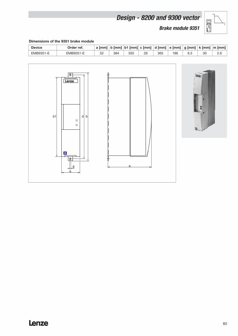
Lenze 83
Design - 8200 and 9300 vectorBrake module 9351
n
t
Dimensions of the 9351 brake module
Device Order ref. a [mm] b [mm] b1 [mm] c [mm] d [mm] e [mm] g [mm] k [mm] m [mm]
EMB9351-E EMB9351-E 52 384 350 26 365 186 6.5 30 2.6
a
bd
eg
Lenze
b1

Lenze84
Design - 8200 and 9300 vectorn
t
Brake chopper 8253 / 9352
8253 and 9352 brake choppers can be optimised for therequired brake power. For this purpose, the brakechoppers are operated with an external brake resistor. Theminimum brake resistance is 47 ohms on the 8253 and18 ohms on the 9352.
The brake chopper can be mounted directly adjacent tothree-phase 8200 frequency inverters (8253 for 8211-18, 9352 for 8241-46, 8221-27 and9321-33EV). If a lower brake power is required, a brakemodule with an integrated brake resistor can be used.
Brake chopper 8253
Supply voltage 450...750 V DC
Threshold at 400 V AC 725 V DC Max. braking energy According to brake resistance
Threshold at 460 V AC 725 V DC Min. brake resistance 47 ohms
Max. current 15 A DC Ambient temperature 0...+ 40ºC
Continuous brake power 5.6 kW Storage temperature -25...+ 70ºC
Peak brake power 11.2 kW 50 % at max. Humidity Humidity class Fduty time 60 s
Brake chopper 9352
Supply voltage 270...780 V DC
Threshold at 400 V 630 V DC Max. braking energy According to brake resistance
Threshold at 460 V 725 V DC Min. brake resistance 18 ohms internal
Threshold at 480 V 765 V DC
Max. current 42 A DC Ambient temperature 0...40ºC
Continuous braking power 19 kW Storage temperature -20...70ºC
Peak braking power 32.0 kW 50 % at max. Humidity Humidity class Fduty time 60 s
Technical data for the 8253 / 9352 brake choppers
Assignment of brake resistor/brake chopper to frequency inverter (example for standard application)
Device Brake chopper Brake resistor
Order ref. Minimum Order ref. Resis- Peak Perm. Thermal mResistance tance power power capacity
[ohm] [ohm] [kW] [W] [kWs] [kg]
8211 EMB8253-E 47 ERBM470R100W 470 1.0 100 15 0.6
8212 EMB8253-E 47 ERBM370R150W 370 1.5 150 22.5 1.0
8213 EMB8253-E 47 ERBM240R200W 240 2.0 200 30 1.3
8214 EMB8253-E 47 ERBD180R300W 180 3.0 300 45 2.0
8215 EMB8253-E 47 ERBD100R600W 100 5.5 600 90 3.1
8216 EMB8253-E 47 ERBD082R600W 82 6.5 600 90 4.1
8217 EMB8253-E 47 ERBD068R800W 68 8.0 800 120 4.1
8218 EMB8253-E 47 ERBD047R01k2 47 12.0 1200 180 4.9
8241 / 9321EV EMB9352-E 18 ERBM470R050W 470 1.0 100 15.0 0.6
8242 / 9322EV EMB9352-E 18 ERBM470R100W 470 1.0 100 15.0 0.6
8243 / 9323EV EMB9352-E 18 ERBM370R150W 370 1.5 300 22.5 1.0
8244 / 9324EV EMB9352-E 18 ERBD180R300W 180 3.0 300 45.0 2.0
8245 / 9325EV EMB9352-E 18 ERBD100R600W 100 5.5 600 90.0 3.1
8246 / 9326EV EMB9352-E 18 ERBD047R01k2 47 12.0 1200 180.0 4.9
8221 / 9327EV EMB9352-E 18 ERBD033R02k0 33 17.0 2000 300 7.1
8222 / 9328EV EMB9352-E 18 ERBD022R03k0 22 26.5 3000 450 10.6
8223 / 9329EV EMB9352-E 18 ERBD018R03k0 18 32.5 3000 450 10.6
8224 / 9330EV EMB9352-E (2 x) 18 ERBD022R03k0 (2 x) 22 26.5 3000 450 10.6
8225 / 9331EV EMB9352-E (2 x) 18 ERBD018R03k0 (2 x) 18 26.5 3000 450 10.6
8226 / 9332EV EMB9352-E (3 x) 18 ERBD022R03k0 (3 x) 22 26.5 3000 450 10.6
8227 / 9333EV EMB9352-E (3 x) 18 ERBD018R03k0 (3 x) 18 32.5 3000 450 10.6

Installation on mounting rail Installation on DIN rail
Device Order a b b1 c d e f g k b c1 c2 c3 e f mref. [mm] [mm] [mm] [mm] [mm] [mm] [mm] [mm] [mm] [mm] [mm] [mm] [mm] [mm] [mm] [kg]
8253 EMB8253-E 56 210 – 28 190 170 130 65 30 190 16 98 149 173 133 1.3
9352 EMB9352-E 52 384 350 26 365 186 – 6.5 30 – – – – – – 2.2
Lenze 85
Design - 8200 and 9300 vector Brake chopper 8253 / 9352
n
t
Brake units– Please note:
– The assignments listed in the table for the externalbrake resistors permit a maximum braking time of upto 15 seconds
– The relative duty time of 10% for a maximum of15 seconds
– The reference variable for the assignment is the setpermanent power of the device.
– Although a higher brake power can be achieved byusing other resistors or by connecting a number ofresistors in parallel or series, the resistance value mustnot fall below the minimum specified.
– All brake resistors listed have integrated temperaturemonitoring with potential-free alarm contact forswitching off the mains contactor.
-UG +UG RB1 RB2 PE (T1) (T2)
a e
b
f
d
gk
Connection example with brake module
K10
K10
L3N
PE
L1L2
U V W
M3˜PE
K10
F1...F3
8211 - 8214
+UG-UG
825228 E1 20PE Z1
X1
Z2
K10
OFF
ON
RFR
RB
T1 T2
...
L1 L2 L3 +UG-UG
Z3
PE
PE PE
Dimensions of brake choppers
a
bd
eg
Lenze
b1
8253
9352

Lenze86
Design - 8200 and 9300 vectorn
t
Brake resistors for the 8253 brake chopper
c
a
dbg
e
k
Dimensions of ERBM module brake resistors
Brake resistor a [mm] b [mm] c [mm] d [mm] e [mm] g [mm] k [mm]
ERBM470R100W 60 240 50 225 60 5 7.5
ERBM470R100W 70 240 50 225 60 5 7.5
ERBM370R150W 80 240 70 225 95 5 7.5
ERBM240R200W 80 340 70 325 70 5 7.5
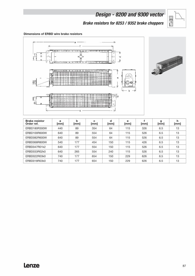
Lenze 87
Design - 8200 and 9300 vector Brake resistors for 8253 / 9352 brake choppers
n
t
Dimensions of ERBD wire brake resistors
Brake resistor a b c d e f g hOrder ref. [mm] [mm] [mm] [mm] [mm] [mm] [mm] [mm]
ERBD180R300W 440 89 354 64 115 326 6.5 13
ERBD100R600W 640 89 554 64 115 526 6.5 13
ERBD082R600W 640 89 554 64 115 526 6.5 13
ERBD068R800W 540 177 454 150 115 426 6.5 13
ERBD047R01k2 640 177 554 150 115 526 6.5 13
ERBD033R02k0 640 265 554 240 115 526 6.5 13
ERBD022R03k0 740 177 654 150 229 626 6.5 13
ERBD018R03k0 740 177 654 150 229 626 6.5 13
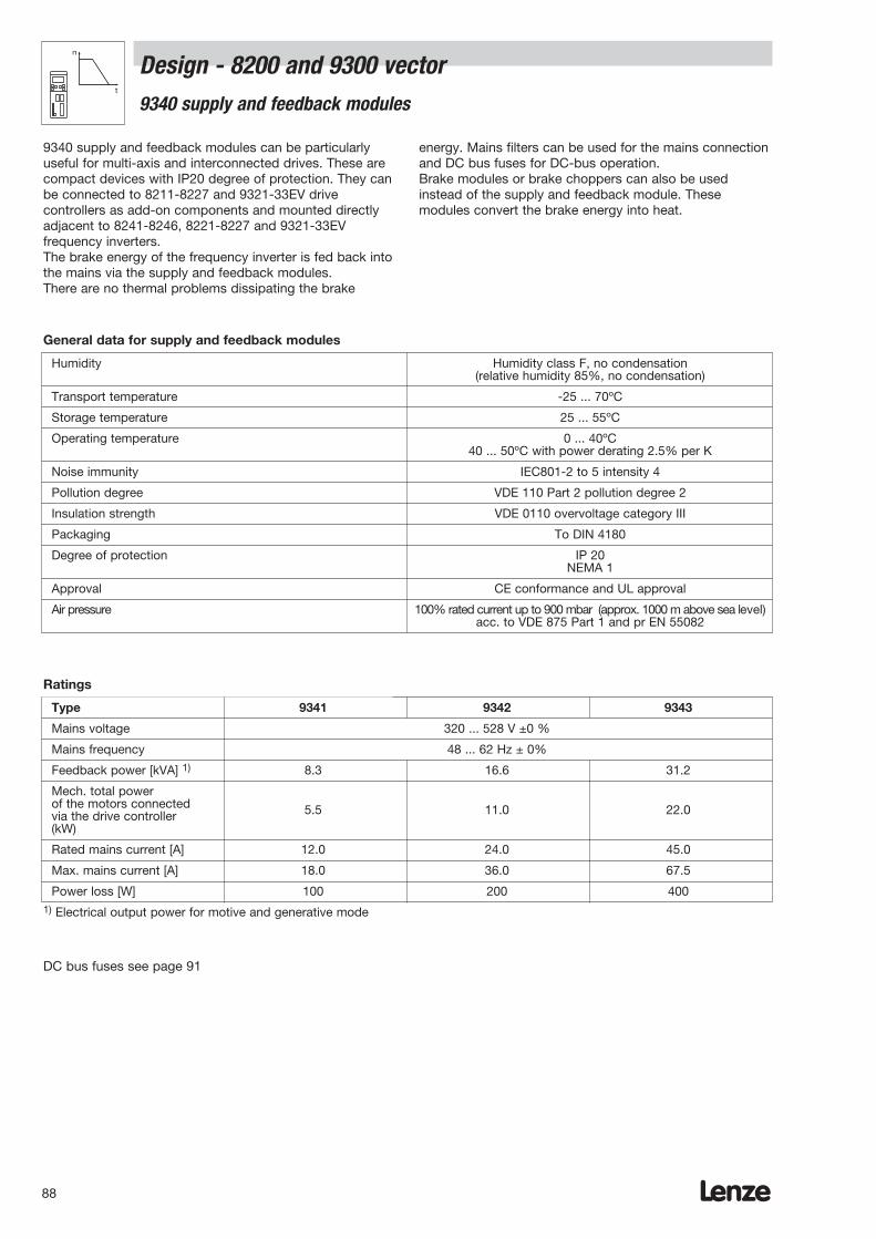
Lenze88
Design - 8200 and 9300 vectorn
t
9340 supply and feedback modules
9340 supply and feedback modules can be particularlyuseful for multi-axis and interconnected drives. These arecompact devices with IP20 degree of protection. They canbe connected to 8211-8227 and 9321-33EV drivecontrollers as add-on components and mounted directlyadjacent to 8241-8246, 8221-8227 and 9321-33EVfrequency inverters.The brake energy of the frequency inverter is fed back intothe mains via the supply and feedback modules.There are no thermal problems dissipating the brake
energy. Mains filters can be used for the mains connectionand DC bus fuses for DC-bus operation.Brake modules or brake choppers can also be usedinstead of the supply and feedback module. Thesemodules convert the brake energy into heat.
Humidity Humidity class F, no condensation (relative humidity 85%, no condensation)
Transport temperature -25 ... 70ºC
Storage temperature 25 ... 55ºC
Operating temperature 0 ... 40ºC40 ... 50ºC with power derating 2.5% per K
Noise immunity IEC801-2 to 5 intensity 4
Pollution degree VDE 110 Part 2 pollution degree 2
Insulation strength VDE 0110 overvoltage category III
Packaging To DIN 4180
Degree of protection IP 20NEMA 1
Approval CE conformance and UL approval
Air pressure 100% rated current up to 900 mbar (approx. 1000 m above sea level)acc. to VDE 875 Part 1 and pr EN 55082
General data for supply and feedback modules
Ratings
Type 9341 9342 9343
Mains voltage 320 ... 528 V ±0 %
Mains frequency 48 ... 62 Hz ± 0%
Feedback power [kVA] 1) 8.3 16.6 31.2
Mech. total powerof the motors connectedvia the drive controller 5.5 11.0 22.0
(kW)
Rated mains current [A] 12.0 24.0 45.0
Max. mains current [A] 18.0 36.0 67.5
Power loss [W] 100 200 4001) Electrical output power for motive and generative mode
DC bus fuses see page 91
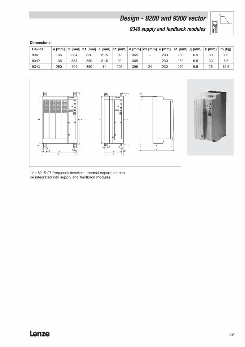
Lenze 89
Design - 8200 and 9300 vector n
t
9340 supply and feedback modules
Dimensions
Device a [mm] b [mm] b1 [mm] c [mm] c1 [mm] d [mm] d1 [mm] e [mm] e1 [mm] g [mm] k [mm] m [kg]
9341 135 384 350 21.5 92 365 – 230 250 6.5 30 7.5
9342 135 384 350 21.5 92 365 – 230 250 6.5 30 7.5
9343 250 404 350 14 205 396 24 230 250 6.5 25 12.5
c1a
bd
e1g
b1
Lenze
c1a
bd
m
b1
Lenze
d1k
g
e
c
k
c
Like 8215-27 frequency inverters, thermal separation canbe integrated into supply and feedback modules.
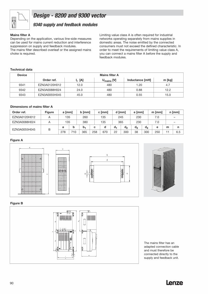
Lenze90
Design - 8200 and 9300 vector n
t
9340 supply and feedback modules
Mains filter ADepending on the application, various line-side measurescan be used for mains current reduction and interferencesuppression on supply and feedback modules.The mains filter described overleaf or the assigned mainschoke is required.
Limiting value class A is often required for industrialnetworks operating separately from mains supplies indomestic areas. The noise emitted by the connectedconsumers must not exceed the defined characteristic. Inorder to meet the requirements of limiting value class A,you can connect a mains filter A before the supply andfeedback modules.
Device Mains filter A
Order ref. Ir [A] Umains [V] Inductance [mH] m [kg]
9341 EZN3A0120H012 12.0 480 1.20 4.7
9342 EZN3A0088H024 24.0 480 0.88 12.2
9343 EZN3A0055H045 45.0 480 0.55 15.0
Technical data
Dimensions of mains filter A
Order ref. Figure a [mm] b [mm] c [mm] d [mm] e [mm] m [mm] n [mm]
EZN3A0120H012 A 135 260 135 245 230 7.0 –
EZN3A0088H024 A 135 380 135 365 230 7.0 –
EZN3A0055H045 Ba b b1 c d d1 d2 d3 d4 e m n
278 710 365 258 670 22 300 38 300 250 11 6.5
d
Figure A
Figure B
c
The mains filter has anadapted connection cableand must therefore beconnected directly to thesupply and feedback unit.
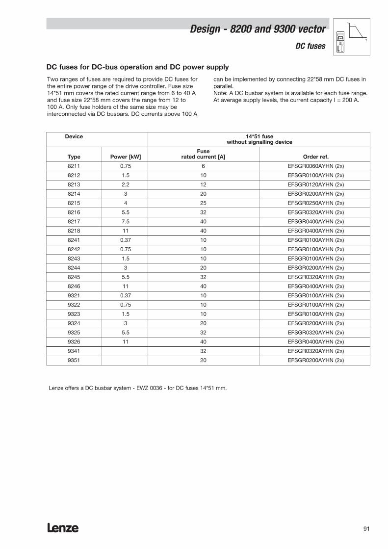
Lenze 91
Design - 8200 and 9300 vectorn
t
DC fuses
Two ranges of fuses are required to provide DC fuses forthe entire power range of the drive controller. Fuse size14*51 mm covers the rated current range from 6 to 40 Aand fuse size 22*58 mm covers the range from 12 to100 A. Only fuse holders of the same size may beinterconnected via DC busbars. DC currents above 100 A
can be implemented by connecting 22*58 mm DC fuses inparallel.Note: A DC busbar system is available for each fuse range.At average supply levels, the current capacity I = 200 A.
Lenze offers a DC busbar system - EWZ 0036 - for DC fuses 14*51 mm.
DC fuses for DC-bus operation and DC power supply
Device 14*51 fusewithout signalling device
FuseType Power [kW] rated current [A] Order ref.
8211 0.75 6 EFSGR0060AYHN (2x)
8212 1.5 10 EFSGR0100AYHN (2x)
8213 2.2 12 EFSGR0120AYHN (2x)
8214 3 20 EFSGR0200AYHN (2x)
8215 4 25 EFSGR0250AYHN (2x)
8216 5.5 32 EFSGR0320AYHN (2x)
8217 7.5 40 EFSGR0400AYHN (2x)
8218 11 40 EFSGR0400AYHN (2x)
8241 0.37 10 EFSGR0100AYHN (2x)
8242 0.75 10 EFSGR0100AYHN (2x)
8243 1.5 10 EFSGR0100AYHN (2x)
8244 3 20 EFSGR0200AYHN (2x)
8245 5.5 32 EFSGR0320AYHN (2x)
8246 11 40 EFSGR0400AYHN (2x)
9321 0.37 10 EFSGR0100AYHN (2x)
9322 0.75 10 EFSGR0100AYHN (2x)
9323 1.5 10 EFSGR0100AYHN (2x)
9324 3 20 EFSGR0200AYHN (2x)
9325 5.5 32 EFSGR0320AYHN (2x)
9326 11 40 EFSGR0400AYHN (2x)
9341 32 EFSGR0320AYHN (2x)
9351 20 EFSGR0200AYHN (2x)
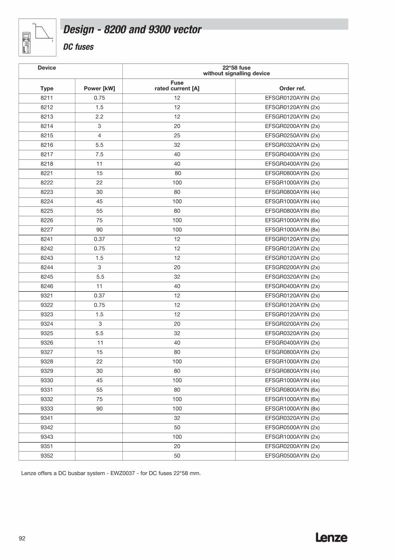
Lenze92
Design - 8200 and 9300 vector n
t
DC fuses
Lenze offers a DC busbar system - EWZ0037 - for DC fuses 22*58 mm.
Device 22*58 fusewithout signalling device
FuseType Power [kW] rated current [A] Order ref.
8211 0.75 12 EFSGR0120AYIN (2x)
8212 1.5 12 EFSGR0120AYIN (2x)
8213 2.2 12 EFSGR0120AYIN (2x)
8214 3 20 EFSGR0200AYIN (2x)
8215 4 25 EFSGR0250AYIN (2x)
8216 5.5 32 EFSGR0320AYIN (2x)
8217 7.5 40 EFSGR0400AYIN (2x)
8218 11 40 EFSGR0400AYIN (2x)
8221 15 80 EFSGR0800AYIN (2x)
8222 22 100 EFSGR1000AYIN (2x)
8223 30 80 EFSGR0800AYIN (4x)
8224 45 100 EFSGR1000AYIN (4x)
8225 55 80 EFSGR0800AYIN (6x)
8226 75 100 EFSGR1000AYIN (6x)
8227 90 100 EFSGR1000AYIN (8x)
8241 0.37 12 EFSGR0120AYIN (2x)
8242 0.75 12 EFSGR0120AYIN (2x)
8243 1.5 12 EFSGR0120AYIN (2x)
8244 3 20 EFSGR0200AYIN (2x)
8245 5.5 32 EFSGR0320AYIN (2x)
8246 11 40 EFSGR0400AYIN (2x)
9321 0.37 12 EFSGR0120AYIN (2x)
9322 0.75 12 EFSGR0120AYIN (2x)
9323 1.5 12 EFSGR0120AYIN (2x)
9324 3 20 EFSGR0200AYIN (2x)
9325 5.5 32 EFSGR0320AYIN (2x)
9326 11 40 EFSGR0400AYIN (2x)
9327 15 80 EFSGR0800AYIN (2x)
9328 22 100 EFSGR1000AYIN (2x)
9329 30 80 EFSGR0800AYIN (4x)
9330 45 100 EFSGR1000AYIN (4x)
9331 55 80 EFSGR0800AYIN (6x)
9332 75 100 EFSGR1000AYIN (6x)
9333 90 100 EFSGR1000AYIN (8x)
9341 32 EFSGR0320AYIN (2x)
9342 50 EFSGR0500AYIN (2x)
9343 100 EFSGR1000AYIN (2x)
9351 20 EFSGR0200AYIN (2x)
9352 50 EFSGR0500AYIN (2x)
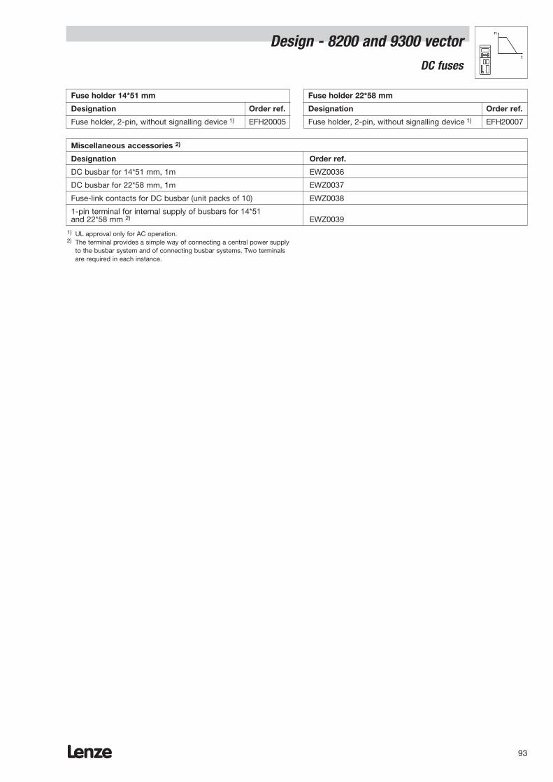
Lenze 93
Design - 8200 and 9300 vectorn
t
DC fuses
Fuse holder 14*51 mm
Designation Order ref.
Fuse holder, 2-pin, without signalling device 1) EFH20005
Fuse holder 22*58 mm
Designation Order ref.
Fuse holder, 2-pin, without signalling device 1) EFH20007
Miscellaneous accessories 2)
Designation Order ref.
DC busbar for 14*51 mm, 1m EWZ0036
DC busbar for 22*58 mm, 1m EWZ0037
Fuse-link contacts for DC busbar (unit packs of 10) EWZ0038
1-pin terminal for internal supply of busbars for 14*51and 22*58 mm 2) EWZ0039
1) UL approval only for AC operation.2) The terminal provides a simple way of connecting a central power supply
to the busbar system and of connecting busbar systems. Two terminalsare required in each instance.
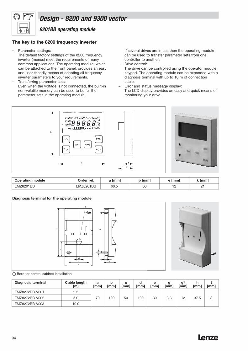
Lenze94
– Parameter settings:The default factory settings of the 8200 frequencyinverter (menus) meet the requirements of manycommon applications. The operating module, whichcan be attached to the front panel, provides an easyand user-friendly means of adapting all frequencyinverter parameters to your requirements.
– Transferring parameter sets:Even when the voltage is not connected, the built-innon-volatile memory can be used to buffer theparameter sets in the operating module.
c
a
b
g
e
d
t
h
g1
¬
If several drives are in use then the operating modulecan be used to transfer parameter sets from onecontroller to another.
– Drive control: The drive can be controlled using the operator modulekeypad. The operating module can be expanded with adiagnosis terminal with up to 10 m of connectioncable.
– Error and status message display:The LCD display provides an easy and quick means ofmonitoring your drive.
The key to the 8200 frequency inverter
Operating module Order ref. a [mm] b [mm] e [mm] k [mm]
EMZ8201BB EMZ8201BB 60.5 60 12 21
Diagnosis terminal for the operating module
Diagnosis terminal Cable length a b c d e g g1 h t[m] [mm] [mm] [mm] [mm] [mm] [mm] [mm] [mm] [mm]
EMZ8272BB-V001 2.5
EMZ8272BB-V002 5.0 70 120 50 100 30 3.8 12 37.5 8
EMZ8272BB-V003 10.0
Bore for control cabinet installation
Design - 8200 and 9300 vector8201BB operating module

Lenze 95
Design - 8200 and 9300 vector 9371BC operating module
– Parameter settings: The default factory settings of the 9300 frequencyinverter (menus) meet the requirements of manycommon applications. The operating module, whichcan be attached to the front panel, provides an easyand user-friendly means of adapting all servo inverterparameters to your requirements.
– Transferring parameter sets:Even when the voltage is not connected, the built-innon-volatile memory can be used to buffer a parameterset in the operating module.
SHIFT
RUN
STOP
Global DRIVEPRG
Par 2SH PRG
Para
1250 rpm0051
MCTRL-N-ACT
RDY IMP Imax Mmax Fail
If several drives are in use then the operating modulecan be used to transfer parameter sets from onecontroller to another.
– Drive control: The drive can be controlled using the operator modulekeypad.
– Error and status message display:The LCD display provides an easy and quick means ofmonitoring your drive.
The key to the 9300 vector frequency inverter
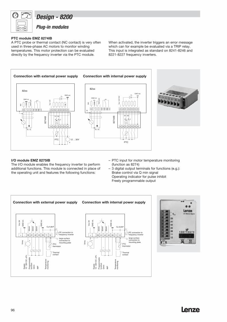
Lenze96
Design - 8200Plug-in modules
PTC module EMZ 8274IBA PTC probe or thermal contact (NC contact) is very oftenused in three-phase AC motors to monitor windingtemperatures. This motor protection can be evaluateddirectly by the frequency inverter via the PTC module.
When activated, the inverter triggers an error messagewhich can for example be evaluated via a TRIP relay. This input is integrated as standard on 8241-8246 and8221-8227 frequency inverters.
I/O module EMZ 8275IBThe I/O module enables the frequency inverter to performadditional functions. This module is connected in place ofthe operating unit and features the following functions:
– PTC input for motor temperature monitoring(function as 8274)
– 3 digital output terminals for functions (e.g.):Brake control via Q min signal Operating indicator for pulse inhibitFreely programmable output
62 7 8 9 K11 K12K14 20 28 E1 E2 E3 E4 39
82xx
20 28 E1 E2 E3 E4 39
PTC 12 ... 30V
-
+
GND int.
GND ext.
3k3
Ure
f 5,2
V
> 1
00k
Vcc
12V
3k
K1
R > 1k
S1 S2
1A
8274
AB
+ - 59 A1 42 45 39 11 12
PTCthermistor
Thermalcontact
+
- -
50m
A
Sup
ply
15 -
30V
DC
±0%
Qm
in
IMP
Tem
pera
ture
mon
itorin
g
50m
A
Pro
gram
mab
lefu
nctio
n
GN
D in
t.
50m
A GN
D in
t.
Vcc
24
Cy 6,8nF
Vrm
s
PE connection tofrequency inverter
large-surfaceconnection tomounting plate
62 7 8 9 K11 K12K14 20 28 E1 E2 E3 E4 39
20 28 E1 E2 E3 E4 39
PTC
S1 S2
1A
82xx
GND int.
GND ext.
K1
R > 1k
8274
AB
3k3
<10
0k
Vre
f 5,2
V
Vcc
12V
/15V
Connection with external power supply Connection with internal power supply
+ - 59 A1 42 45 39 11 12
PTCthermistor
Thermalcontact
+
- -
50m
A
Sup
ply
15 -
30V
DC
±0%
Qm
in
IMP
Tem
pera
ture
mon
itorin
g
50m
A
Pro
gram
mab
lefu
nctio
n
GN
D in
t.
50m
A GN
D in
t.
Vcc
24
Cy 6,8nF
Vrm
s
PE connection tofrequency inverter
large-surfaceconnection tomounting plate
Connection with external power supply Connection with internal power supply

Lenze 97
Design - 8200Plug-in modules
EMZ 8276IB monitor moduleAs standard, the 8200 frequency inverter has a 0 - 6 Vanalog output. If this output is not used as an indicator butis required in another controller, a 0 - 10 V voltage is oftenrequired.
The output voltage is converted as necessaryby the monitor module.
EMZ 8278IB bipolar input moduleIn some applications, the setpoint and direction of rotationare preset via a bipolar voltage ± 10 V. The bipolar analogmodule can be used to connect this voltage directly.
This enables a direct connection to be establishedbetween the open-loop control and the controller. Thissolution can be particularly useful in transportation andmaterial handling applications.
62 7 8 9 K11 K12K14 20 28 E1 E2 E3 E4 39
82xx
12...30 V
-
+
GND 1
GND 2
3k3 Vre
f 5,2
V
> 1
00k
Vcc
12V
/ 15
V
3k
K1
R > 1k
8276
IB
0...10 V2 or5 mA
Ctrl
. ena
ble
JOG
1
JOG
2
DC
bra
ke
CC
W r
otat
ion
62 7 8 9 K11 K12K14
62 7 8 9 K11 K12 K14 20 28 E1 E2 E3 E4 39
3k3
<10
0k
Vre
f 5,2
V
Vcc
12V
/ 15
V
3k
C007 = -14-...-22-
Ctr
l. en
able
CW
/CC
Wro
tatio
n
62 7 R L
8 7 - +
Master voltage
Master current
12...30 Vexternal supply
+ +
- -
+
-
8278IB
82xx
GND int. K1
GND ext.
PE PE
62 7 8 9 K11 K12K14 20 28 E1 E2 E3 E4 39
R > 1k
8276
IB
3k3
<10
0k
Vre
f 5,2
V
Vcc
12V
/ 15
V
3k
62 7 8 9 K11 K12K14
0...10 V2 or5 mA
Ctr
l. en
able
JOG
1JO
G2
DC
bra
ke
CC
W r
otat
ion
82xx
K1
GND 2
GND 1
PE
Connection with external power supply Connection with internal power supply
62 7 8 9 K11 K12K14 20 28 E1 E2 E3 E4 39
GND 1
GND 2
3k3
<10
0k
Vre
f 5,2
V
Vcc
12V
/ 15
V
3k
C007 = -0-...-13-
Ctr
l. en
able
CC
W/C
W r
otat
ion
62 7 R L
8 7 - +
Setpoint inversion
Master voltage
Master current
12...30 Vexternal supply
+ +
- -
+
-
8278IB
82xx
K1
PE PE
R/L connection on two terminals(fail-safe)
R/L connection on one terminal
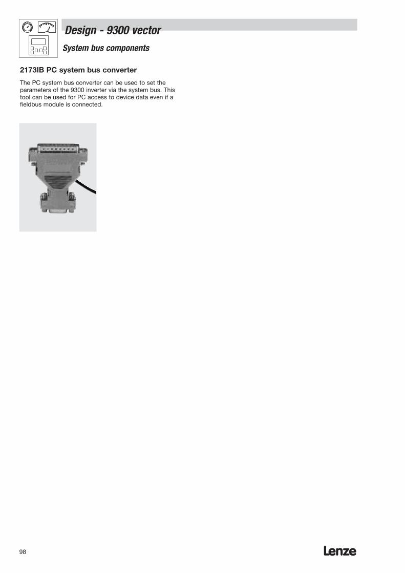
Lenze98
Design - 9300 vectorSystem bus components
The PC system bus converter can be used to set theparameters of the 9300 inverter via the system bus. This tool can be used for PC access to device data even if afieldbus module is connected.
2173IB PC system bus converter

Lenze 99
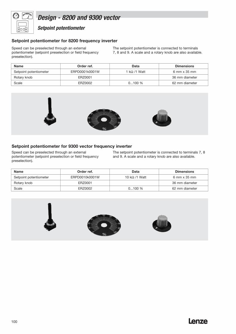
Lenze100
Design - 8200 and 9300 vector Setpoint potentiometer
Speed can be preselected through an externalpotentiometer (setpoint preselection or field frequencypreselection).
The setpoint potentiometer is connected to terminals 7, 8 and 9. A scale and a rotary knob are also available.
Setpoint potentiometer for 8200 frequency inverter
Name Order ref. Data Dimensions
Setpoint potentiometer ERPD0001k0001W 1 kΩ /1 Watt 6 mm x 35 mm
Rotary knob ERZ0001 36 mm diameter
Scale ERZ0002 0...100 % 62 mm diameter
Speed can be preselected through an externalpotentiometer (setpoint preselection or field frequencypreselection).
The setpoint potentiometer is connected to terminals 7, 8and 9. A scale and a rotary knob are also available.
Setpoint potentiometer for 9300 vector frequency inverter
Name Order ref. Data Dimensions
Setpoint potentiometer ERPD0010k0001W 10 kΩ /1 Watt 6 mm x 35 mm
Rotary knob ERZ0001 36 mm diameter
Scale ERZ0002 0...100 % 62 mm diameter
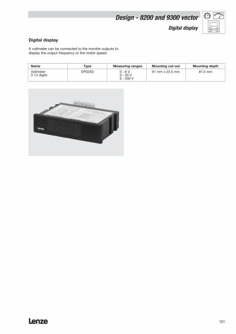
Lenze 101
Design - 8200 and 9300 vector Digital display
Digital display
A voltmeter can be connected to the monitor outputs todisplay the output frequency or the motor speed.
Name Type Measuring ranges Mounting cut-out Mounting depth
Voltmeter EPD203 0 - 6 V000 91 mm x 22.5 mm 81.5 mm3 1/2 digits 0 - 20 V00
0 - 200 V0

Lenze102
Design - 8200Communication with a host system
Networking via the RS 232/485 interface
Attachable modules provide an easy way of networking82XX frequency inverters e.g. with an RS 232 or RS 485interface on a host system (PLC or PC). The modules areattached in place of the operating module. Three versionsare available:
– 2102IBV001: RS 232/485 interface– 2102IBV002: RS 485 interface
The RS 232 and RS 485 interfaces have been designedas 9-pin SUB-D connectors. On the RS 485 interface,there is an additional screw terminal for connectingthrough to the next drive.
– 2102IBV003: Optical fibresNetworking via optical fibres (using a plastic core) iscompletely noise-free and very economical. The opticalfibre can be easily adapted through an optical fibresocket at the module. For the host system we offersimple 2125IB plug-on optical fibre adapters which areattached to the interface of the communication moduleon your PLC.
All three interfaces communicate using the Lenze LECOMprotocol. The LECOM protocol is completely open for yourown applications. It is however also already integrated invarious systems (e.g. Simatic S5), offering a simple optionfor integration into a control system. Lenze Global DriveControl 1 software can be used for parameter setting.
Networking via a system bus (CAN)
The 2171IB and 2172IB system bus modules are slavemodules with the communication module to CIA DS 301.These modules can be used to preselect and read out allof the parameters of the drive. Process data can betransmitted directly in conjunction with a small controlsystem.The 2172IB system bus module can be used topreset the data transmission speed and the addressing(via program switches) for the drive controller. This moduleis particularly useful for servicing applications.
Networking via host systems with high processingspeeds– InterBus-S module 2111IB
The InterBus-S link via the 2111 module is connecteddirectly to the remote bus. The DRIVECOM profile 21 issupported for this connection. A 9-pin SUB-Dconnector is used for this extremely user-friendly wayof networking a drive controller. A 15 V connection foran external power supply to the remote bus is alsoavailable on the module.
– Profibus module 2131IBThe PROFIBUS-DP function module is a slaveconnection module with the PROFIBUS-DPcommunication profile. This module can simply beattached in the same way as the other fieldbus module.It is an interesting way of connecting to a process withaverage process dynamics.
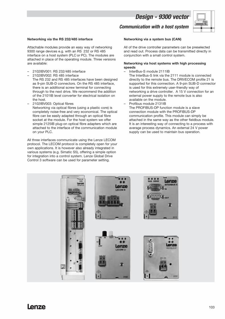
Lenze 103
Design - 9300 vector Communication with a host system
Networking via the RS 232/485 interface
Attachable modules provide an easy way of networking9300 range devices e.g. with an RS 232 or RS 485interface on a host system (PLC or PC). The modules areattached in place of the operating module. Three versionsare available:
– 2102IBV001: RS 232/485 interface– 2102IBV002: RS 485 interface
The RS 232 and RS 485 interfaces have been designedas 9-pin SUB-D connectors. On the RS 485 interface, there is an additional screw terminal for connectingthrough to the next drive. We recommend the additionof the 2101IB level converter for electrical isolation onthe host.
– 2102IBV003: Optical fibresNetworking via optical fibres (using a plastic core) iscompletely noise-free and very economical. The opticalfibre can be easily adapted through an optical fibresocket at the module. For the host system we offersimple 2125IB plug-on optical fibre adapters which areattached to the interface of the communication moduleon your PLC.
All three interfaces communicate using the Lenze LECOMprotocol. The LECOM protocol is completely open for yourown applications. It is however also already integrated invarious systems (e.g. Simatic S5), offering a simple optionfor integration into a control system. Lenze Global DriveControl 3 software can be used for parameter setting.
Networking via a system bus (CAN)
All of the drive controller parameters can be preselectedand read out. Process data can be transmitted directly inconjunction with a small control system.
Networking via host systems with high processingspeeds– InterBus-S module 2111IB
The InterBus-S link via the 2111 module is connecteddirectly to the remote bus. The DRIVECOM profile 21 issupported for this connection. A 9-pin SUB-D connectoris used for this extremely user-friendly way ofnetworking a drive controller. A 15 V connection for anexternal power supply to the remote bus is alsoavailable on the module.
– Profibus module 2131IBThe PROFIBUS-DP function module is a slaveconnection module with the PROFIBUS-DPcommunication profile. This module can simply beattached in the same way as the other fieldbus module.It is an interesting way of connecting to a process withaverage process dynamics. An external 24 V powersupply can be used to maintain bus operation.
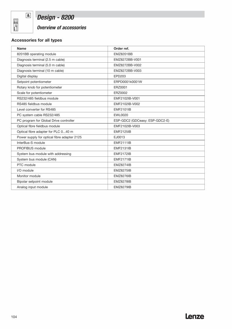
Lenze104
Design - 8200Overview of accessories
&
Name Order ref.
8201BB operating module EMZ8201BB
Diagnosis terminal (2.5 m cable) EMZ8272BB-V001
Diagnosis terminal (5.0 m cable) EMZ8272BB-V002
Diagnosis terminal (10 m cable) EMZ8272BB-V003
Digital display EPD203
Setpoint potentiometer ERPD0001k0001W
Rotary knob for potentiometer ERZ0001
Scale for potentiometer ERZ0002
RS232/485 fieldbus module EMF2102IB-V001
RS485 fieldbus module EMF2102IB-V002
Level converter for RS485 EMF2101IB
PC system cable RS232/485 EWL0020
PC program for Global Drive controller ESP-GDC2 (GDCeasy: ESP-GDC2-E)
Optical fibre fieldbus module EMF2102IB-V003
Optical fibre adapter for PLC 0...40 m EMF2125IB
Power supply for optical fibre adapter 2125 EJ0013
InterBus-S module EMF2111IB
PROFIBUS module EMF2131IB
System bus module with addressing EMF2172IB
System bus module (CAN) EMF2171IB
PTC module EMZ8274IB
I/O module EMZ8275IB
Monitor module EMZ8276IB
Bipolar setpoint module EMZ8278IB
Analog input module EMZ8279IB
Accessories for all types

Lenze 105
Name Order ref.
Device 8201 8202 8203 8204
Automatic circuit-breaker EFA1C10A EFA1C16A EFA1C20A EFA1C20A
Fuse EFSM-0100ASB EFSM-0150ASB EFSM-0200ASC EFSM-0200ASC
Fuse holder EFH30001 EFH30001 EFH30001 EFH30001
Mains filter type “A” EZN2-004A001 EZN2-008A001 EZN2-013A001 EZN2-017A001
Mains choke ELN1-0900H005 ELN1-0500H009 ELN1-0350H014 ELN1-0160H017
RFI filter for operation with mains choke EZF1-006A002 EZF1-009A002 EZF1-018A002 EZF1-018A002without mains choke EZF1-006A002 EZF1-009A002 EZF1-018A002 Not permitted
Motor filter ELM3-030H003 ELM3-020H004 ELM3-010H010 ELM3-014H010
Sinusoidal filter EZS3-003A001 EZS3-004A002 EZS3-007A001 EZS3-010A001
Brake module EMB8251-E EMB8251-E EMB8251-E EMB8251-E
Swivel wall EJ0001 EJ0001 EJ0001 EJ0002fastening
DIN rail EJ0002 EJ0002 EJ0002 EJ0002mounting
Fan for surface EJ0003 EJ0003 EJ0003 EJ0003mounting
Current limitingmodule EMZ8201AB EMZ8201AB EMZ8203AB EMZ8203AB
Type-specific accessories 8201 to 8204
Overview of accessories
Design - 8200 &
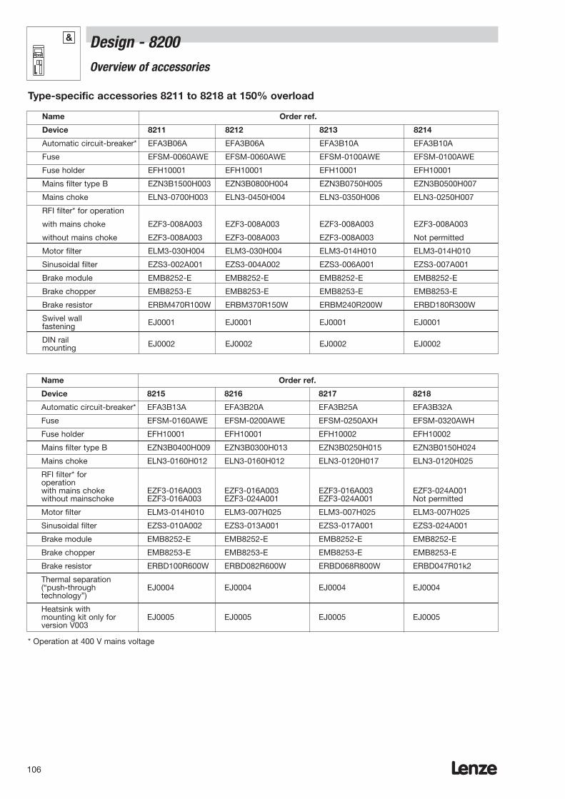
Lenze106
Name Order ref.
Device 8211 8212 8213 8214
Automatic circuit-breaker* EFA3B06A EFA3B06A EFA3B10A EFA3B10A
Fuse EFSM-0060AWE EFSM-0060AWE EFSM-0100AWE EFSM-0100AWE
Fuse holder EFH10001 EFH10001 EFH10001 EFH10001
Mains filter type B EZN3B1500H003 EZN3B0800H004 EZN3B0750H005 EZN3B0500H007
Mains choke ELN3-0700H003 ELN3-0450H004 ELN3-0350H006 ELN3-0250H007
RFI filter* for operation
with mains choke EZF3-008A003 EZF3-008A003 EZF3-008A003 EZF3-008A003
without mains choke EZF3-008A003 EZF3-008A003 EZF3-008A003 Not permitted
Motor filter ELM3-030H004 ELM3-030H004 ELM3-014H010 ELM3-014H010
Sinusoidal filter EZS3-002A001 EZS3-004A002 EZS3-006A001 EZS3-007A001
Brake module EMB8252-E EMB8252-E EMB8252-E EMB8252-E
Brake chopper EMB8253-E EMB8253-E EMB8253-E EMB8253-E
Brake resistor ERBM470R100W ERBM370R150W ERBM240R200W ERBD180R300W
Swivel wall fastening EJ0001 EJ0001 EJ0001 EJ0001
DIN rail mounting EJ0002 EJ0002 EJ0002 EJ0002
Type-specific accessories 8211 to 8218 at 150% overload
Name Order ref.
Device 8215 8216 8217 8218
Automatic circuit-breaker* EFA3B13A EFA3B20A EFA3B25A EFA3B32A
Fuse EFSM-0160AWE EFSM-0200AWE EFSM-0250AXH EFSM-0320AWH
Fuse holder EFH10001 EFH10001 EFH10002 EFH10002
Mains filter type B EZN3B0400H009 EZN3B0300H013 EZN3B0250H015 EZN3B0150H024
Mains choke ELN3-0160H012 ELN3-0160H012 ELN3-0120H017 ELN3-0120H025
RFI filter* for operationwith mains choke EZF3-016A003 EZF3-016A003 EZF3-016A003 EZF3-024A001without mainschoke EZF3-016A003 EZF3-024A001 EZF3-024A001 Not permitted
Motor filter ELM3-014H010 ELM3-007H025 ELM3-007H025 ELM3-007H025
Sinusoidal filter EZS3-010A002 EZS3-013A001 EZS3-017A001 EZS3-024A001
Brake module EMB8252-E EMB8252-E EMB8252-E EMB8252-E
Brake chopper EMB8253-E EMB8253-E EMB8253-E EMB8253-E
Brake resistor ERBD100R600W ERBD082R600W ERBD068R800W ERBD047R01k2
Thermal separation(“push-through EJ0004 EJ0004 EJ0004 EJ0004technology”)
Heatsink with mounting kit only for EJ0005 EJ0005 EJ0005 EJ0005version V003
* Operation at 400 V mains voltage
Design - 8200Overview of accessories
&
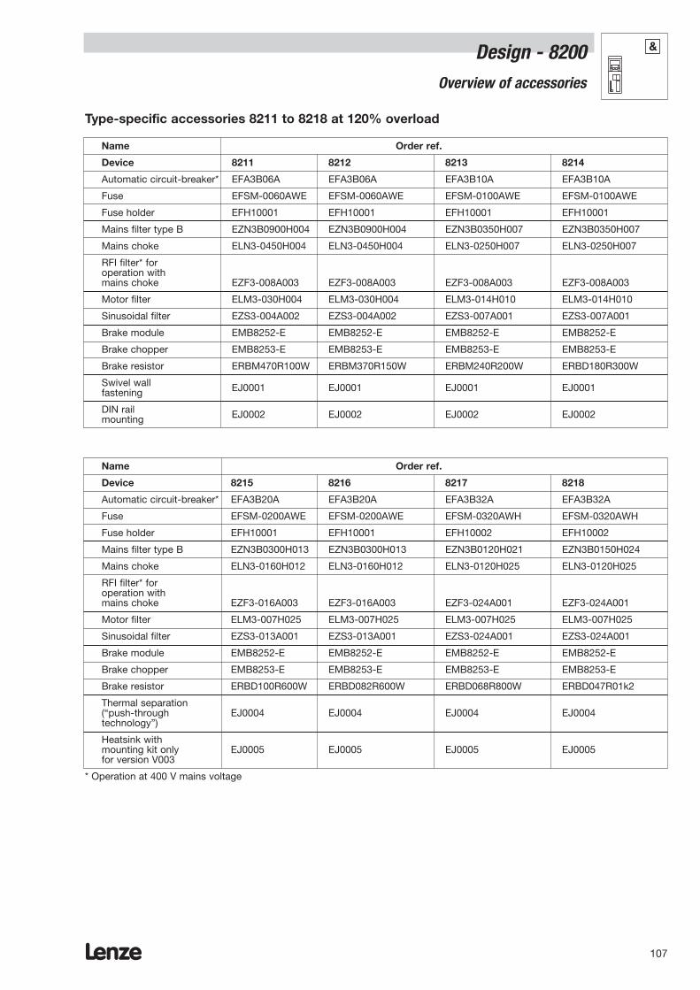
Lenze 107
Design - 8200Overview of accessories
&
Name Order ref.
Device 8211 8212 8213 8214
Automatic circuit-breaker* EFA3B06A EFA3B06A EFA3B10A EFA3B10A
Fuse EFSM-0060AWE EFSM-0060AWE EFSM-0100AWE EFSM-0100AWE
Fuse holder EFH10001 EFH10001 EFH10001 EFH10001
Mains filter type B EZN3B0900H004 EZN3B0900H004 EZN3B0350H007 EZN3B0350H007
Mains choke ELN3-0450H004 ELN3-0450H004 ELN3-0250H007 ELN3-0250H007
RFI filter* for operation withmains choke EZF3-008A003 EZF3-008A003 EZF3-008A003 EZF3-008A003
Motor filter ELM3-030H004 ELM3-030H004 ELM3-014H010 ELM3-014H010
Sinusoidal filter EZS3-004A002 EZS3-004A002 EZS3-007A001 EZS3-007A001
Brake module EMB8252-E EMB8252-E EMB8252-E EMB8252-E
Brake chopper EMB8253-E EMB8253-E EMB8253-E EMB8253-E
Brake resistor ERBM470R100W ERBM370R150W ERBM240R200W ERBD180R300W
Swivel wall fastening EJ0001 EJ0001 EJ0001 EJ0001
DIN railmounting EJ0002 EJ0002 EJ0002 EJ0002
Type-specific accessories 8211 to 8218 at 120% overload
Name Order ref.
Device 8215 8216 8217 8218
Automatic circuit-breaker* EFA3B20A EFA3B20A EFA3B32A EFA3B32A
Fuse EFSM-0200AWE EFSM-0200AWE EFSM-0320AWH EFSM-0320AWH
Fuse holder EFH10001 EFH10001 EFH10002 EFH10002
Mains filter type B EZN3B0300H013 EZN3B0300H013 EZN3B0120H021 EZN3B0150H024
Mains choke ELN3-0160H012 ELN3-0160H012 ELN3-0120H025 ELN3-0120H025
RFI filter* for operation withmains choke EZF3-016A003 EZF3-016A003 EZF3-024A001 EZF3-024A001
Motor filter ELM3-007H025 ELM3-007H025 ELM3-007H025 ELM3-007H025
Sinusoidal filter EZS3-013A001 EZS3-013A001 EZS3-024A001 EZS3-024A001
Brake module EMB8252-E EMB8252-E EMB8252-E EMB8252-E
Brake chopper EMB8253-E EMB8253-E EMB8253-E EMB8253-E
Brake resistor ERBD100R600W ERBD082R600W ERBD068R800W ERBD047R01k2
Thermal separation(“push-through EJ0004 EJ0004 EJ0004 EJ0004technology”)
Heatsink with mounting kit only EJ0005 EJ0005 EJ0005 EJ0005for version V003
* Operation at 400 V mains voltage
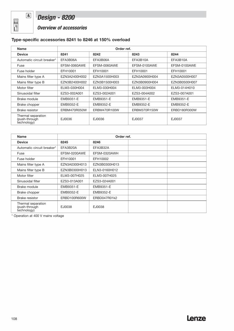
Lenze108
Design - 8200Overview of accessories
&
Name Order ref.
Device 8241 8242 8243 8244
Automatic circuit breaker* EFA3B06A EFA3B06A EFA3B10A EFA3B10A
Fuse EFSM-0060AWE EFSM-0060AWE EFSM-0100AWE EFSM-0100AWE
Fuse holder EFH10001 EFH10001 EFH10001 EFH10001
Mains filter type A EZN3A2400H002 EZN3A1500H003 EZN3A0900H004 EZN3A0500H007
Mains filter type B EZN3B2400H002 EZN3B1500H003 EZN3B0900H004 EZN3B0500H007
Motor filter ELM3-030H004 ELM3-030H004 ELM3-003H004 ELM3-014H010
Sinusoidal filter EZS3-002A001 EZS3-002A001 EZS3-004A002 EZS3-007A001
Brake module EMB9351-E EMB9351-E EMB9351-E EMB9351-E
Brake chopper EMB9352-E EMB9352-E EMB9352-E EMB9352-E
Brake resistor ERBM470R050W ERBM470R100W ERBM370R150W ERBD180R300W
Thermal separation(push-through EJ0036 EJ0036 EJ0037 EJ0037technology)
Type-specific accessories 8241 to 8246 at 150% overload
Name Order ref.
Device 8245 8246
Automatic circuit breaker* EFA3B20A EFA3B32A
Fuse EFSM-0200AWE EFSM-0320AWH
Fuse holder EFH10001 EFH10002
Mains filter type A EZN3A0300H013 EZN3B0300H013
Mains filter type B EZN3B0300H013 ELN3-0160H012
Motor filter ELM3-007H025 ELM3-007H025
Sinusoidal filter EZS3-013A001 EZS3-024A001
Brake module EMB9351-E EMB9351-E
Brake chopper EMB9352-E EMB9352-E
Brake resistor ERBD100R600W ERBD047R01k2
Thermal separation(push-through EJ0038 EJ0038technology)
* Operation at 400 V mains voltage
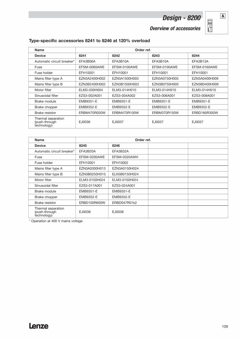
Lenze 109
Name Order ref.
Device 8241 8242 8243 8244
Automatic circuit breaker* EFA3B06A EFA3B10A EFA3B10A EFA3B13A
Fuse EFSM-0060AWE EFSM-0100AWE EFSM-0100AWE EFSM-0160AWE
Fuse holder EFH10001 EFH10001 EFH10001 EFH10001
Mains filter type A EZN3A2400H002 EZN3A1500H003 EZN3A0750H005 EZN3A0400H009
Mains filter type B EZN3B2400H002 EZN3B1500H003 EZN3B0750H005 EZN3B0400H009
Motor filter ELM3-030H004 ELM3-014H010 ELM3-014H010 ELM3-014H010
Sinusoidal filter EZS3-002A001 EZS3-004A002 EZS3-006A001 EZS3-008A001
Brake module EMB9351-E EMB9351-E EMB9351-E EMB9351-E
Brake chopper EMB9352-E EMB9352-E EMB9352-E EMB9352-E
Brake resistor ERBM470R050W ERBM470R100W ERBM370R150W ERBD180R300W
Thermal separation(push-through EJ0036 EJ0037 EJ0037 EJ0037technology)
Type-specific accessories 8241 to 8246 at 120% overload
Name Order ref.
Device 8245 8246
Automatic circuit breaker* EFA3B20A EFA3B32A
Fuse EFSM-0200AWE EFSM-0320AWH
Fuse holder EFH10001 EFH10002
Mains filter type A EZN3A0300H013 EZN3A0150H024
Mains filter type B EZN3B0250H015 ELN3B0150H024
Motor filter ELM3-0150H024 ELM3-0150H024
Sinusoidal filter EZS3-017A001 EZS3-024A001
Brake module EMB9351-E EMB9351-E
Brake chopper EMB9352-E EMB9352-E
Brake resistor ERBD100R600W ERBD047R01k2
Thermal separation(push-through EJ0038 EJ0038technology)
* Operation at 400 V mains voltage
Design - 8200Overview of accessories
&
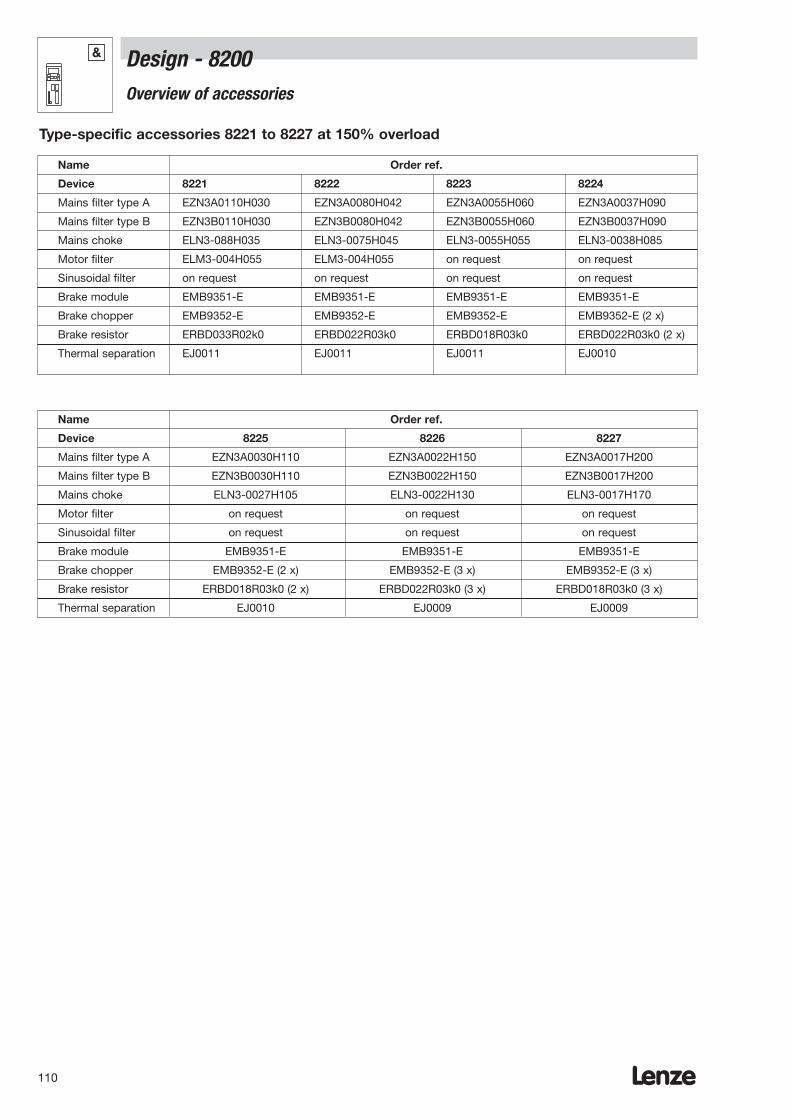
Lenze110
Name Order ref.
Device 8225 8226 8227
Mains filter type A EZN3A0030H110 EZN3A0022H150 EZN3A0017H200
Mains filter type B EZN3B0030H110 EZN3B0022H150 EZN3B0017H200
Mains choke ELN3-0027H105 ELN3-0022H130 ELN3-0017H170
Motor filter on request on request on request
Sinusoidal filter on request on request on request
Brake module EMB9351-E EMB9351-E EMB9351-E
Brake chopper EMB9352-E (2 x) EMB9352-E (3 x) EMB9352-E (3 x)
Brake resistor ERBD018R03k0 (2 x) ERBD022R03k0 (3 x) ERBD018R03k0 (3 x)
Thermal separation EJ0010 EJ0009 EJ0009
Name Order ref.
Device 8221 8222 8223 8224
Mains filter type A EZN3A0110H030 EZN3A0080H042 EZN3A0055H060 EZN3A0037H090
Mains filter type B EZN3B0110H030 EZN3B0080H042 EZN3B0055H060 EZN3B0037H090
Mains choke ELN3-088H035 ELN3-0075H045 ELN3-0055H055 ELN3-0038H085
Motor filter ELM3-004H055 ELM3-004H055 on request on request
Sinusoidal filter on request on request on request on request
Brake module EMB9351-E EMB9351-E EMB9351-E EMB9351-E
Brake chopper EMB9352-E EMB9352-E EMB9352-E EMB9352-E (2 x)
Brake resistor ERBD033R02k0 ERBD022R03k0 ERBD018R03k0 ERBD022R03k0 (2 x)
Thermal separation EJ0011 EJ0011 EJ0011 EJ0010
Type-specific accessories 8221 to 8227 at 150% overload
Design - 8200Overview of accessories
&
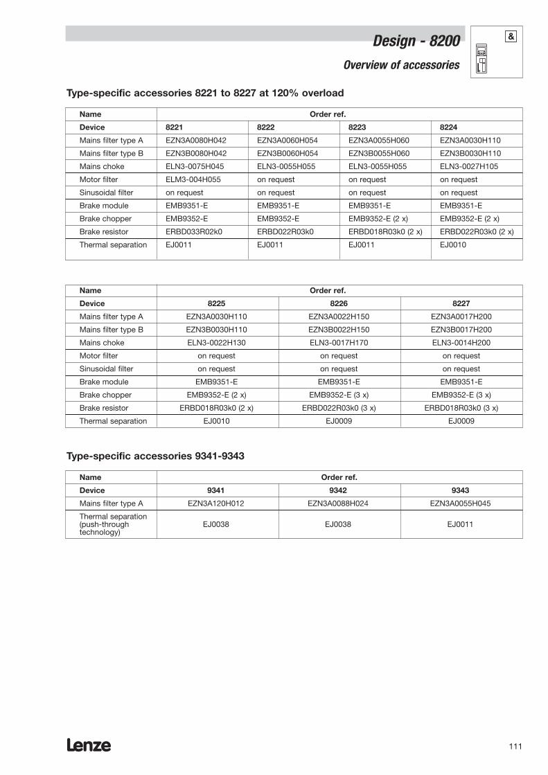
Lenze 111
Design - 8200Overview of accessories
&
Name Order ref.
Device 8225 8226 8227
Mains filter type A EZN3A0030H110 EZN3A0022H150 EZN3A0017H200
Mains filter type B EZN3B0030H110 EZN3B0022H150 EZN3B0017H200
Mains choke ELN3-0022H130 ELN3-0017H170 ELN3-0014H200
Motor filter on request on request on request
Sinusoidal filter on request on request on request
Brake module EMB9351-E EMB9351-E EMB9351-E
Brake chopper EMB9352-E (2 x) EMB9352-E (3 x) EMB9352-E (3 x)
Brake resistor ERBD018R03k0 (2 x) ERBD022R03k0 (3 x) ERBD018R03k0 (3 x)
Thermal separation EJ0010 EJ0009 EJ0009
Name Order ref.
Device 8221 8222 8223 8224
Mains filter type A EZN3A0080H042 EZN3A0060H054 EZN3A0055H060 EZN3A0030H110
Mains filter type B EZN3B0080H042 EZN3B0060H054 EZN3B0055H060 EZN3B0030H110
Mains choke ELN3-0075H045 ELN3-0055H055 ELN3-0055H055 ELN3-0027H105
Motor filter ELM3-004H055 on request on request on request
Sinusoidal filter on request on request on request on request
Brake module EMB9351-E EMB9351-E EMB9351-E EMB9351-E
Brake chopper EMB9352-E EMB9352-E EMB9352-E (2 x) EMB9352-E (2 x)
Brake resistor ERBD033R02k0 ERBD022R03k0 ERBD018R03k0 (2 x) ERBD022R03k0 (2 x)
Thermal separation EJ0011 EJ0011 EJ0011 EJ0010
Type-specific accessories 8221 to 8227 at 120% overload
Name Order ref.
Device 9341 9342 9343
Mains filter type A EZN3A120H012 EZN3A0088H024 EZN3A0055H045
Thermal separation(push-through EJ0038 EJ0038 EJ0011technology)
Type-specific accessories 9341-9343
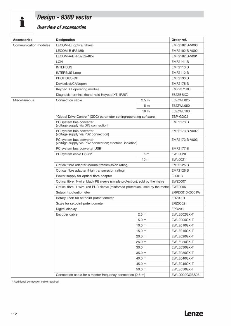
Lenze112
Accessories Designation Order ref.
Communication modules LECOM-LI (optical fibres) EMF2102IB-V003
LECOM-B (RS485) EMF2102IB-V002
LECOM-A/B (RS232/485) EMF2102IB-V001
LON EMF2141IB
INTERBUS EMF2113IB
INTERBUS Loop EMF2112IB
PROFIBUS-DP EMF2133IB
DeviceNet/CANopen EMF2175IB
Keypad XT operating module EMZ9371BC
Diagnosis terminal (hand-held Keypad XT, IP201) E82ZBBXC
Miscellaneous Connection cable 2.5 m E82ZWL025
5 m E82ZWL050
10 m E82ZWL100
“Global Drive Control” (GDC) parameter setting/operating software ESP-GDC2
PC system bus converter EMF2173IB(voltage supply via DIN connection)
PC system bus converter EMF2173IB-V002(voltage supply via PS2 connection)
PC system bus converter EMF2173IB-V003(voltage supply via PS2 connection; electrical isolation)
PC system bus converter USB EMF2177IB
PC system cable RS232 5 m EWL0020
10 m EWL0021
Optical fibre adapter (normal transmission rating) EMF2125IB
Optical fibre adapter (high transmission rating) EMF2126IB
Power supply for optical fibre adapter EJ0013
Optical fibre, 1-wire, black PE sleeve (simple protection), sold by the metre EWZ0007
Optical fibre, 1-wire, red PUR sleeve (reinforced protection), sold by the metre EWZ0006
Setpoint potentiometer ERPD0010K0001W
Rotary knob for setpoint potentiometer ERZ0001
Scale for setpoint potentiometer ERZ0002
Digital display EPD203
Encoder cable 2.5 m EWLE002GX-T
5.0 m EWLE005GX-T
10.0 m EWLE010GX-T
15.0 m EWLE015GX-T
20.0 m EWLE020GX-T
25.0 m EWLE025GX-T
30.0 m EWLE030GX-T
35.0 m EWLE035GX-T
40.0 m EWLE040GX-T
45.0 m EWLE045GX-T
50.0 m EWLE050GX-T
Connection cable for a master frequency connection (2.5 m) EWLD002GGBS93
1) Additional connection cable required
Design - 9300 vectorOverview of accessories
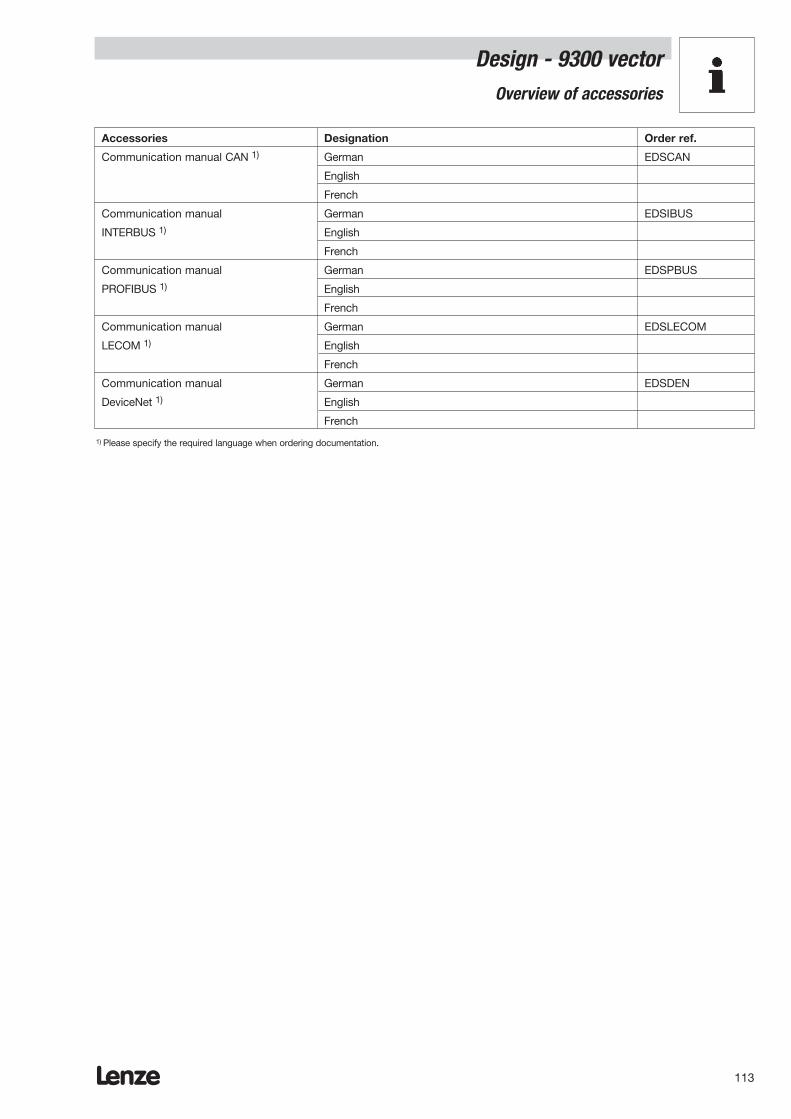
Lenze 113
Design - 9300 vector Overview of accessories
Accessories Designation Order ref.
Communication manual CAN 1) German EDSCAN
English
French
Communication manual German EDSIBUS
INTERBUS 1) English
French
Communication manual German EDSPBUS
PROFIBUS 1) English
French
Communication manual German EDSLECOM
LECOM 1) English
French
Communication manual German EDSDEN
DeviceNet 1) English
French
1) Please specify the required language when ordering documentation.

Lenze114
Design - 9300 vector Overview of accessories
Name Order ref.
Device EVF9321EV EVF9322EV EVF9323EV EVF9324EV
Automatic circuit breaker* EFA3B06A EFA3B06A EFA3B10A EFA3B13A
Fuse EFSM-0060AWE EFSM-0060AWE EFSM-0100AWE EFSM-0160AWE
Fuse holder EFH10001 EFH10001 EFH10001 EFH10001
Mains filter type A EZN3A2400H002 EZN3A1500H003 EZN3A0750H005 EZN3A0400H009
Mains filter type B EZN3B2400H002 EZN3B1500H003 EZN3B0750H005 EZN3B0400H009
Motor filter ELM3-030H004 ELM3-030H004 ELM3-014H010 ELM3-007H025
Sinusoidal filter EZS3-002A001 EZS3-004A002 EZS3-006A001 EZS3-009A002
Brake module EMB9351-E EMB9351-E EMB9351-E EMB9351-E
Brake chopper EMB9352-E EMB9352-E EMB9352-E EMB9352-E
Brake resistor ERBM470R050W ERBM470R100W ERBM370R150W ERBD180R300W
Thermal separation(push-through EJ0036 EJ0037 EJ0037 EJ0037technology)
Type-specific accessories 9321EV to 9326EV at 120% overload
Name Order ref.
Device EVF9325EV EVF9326EV
Automatic circuit breaker* EFA3B20A EFA3B32A
Fuse EFSM-0200AWE EFSM-0320AWH
Fuse holder EFH10001 EFH10002
Mains filter type A EZN3A0300H013 EZN3A0150H024
Mains filter type B EZN3B0250H015 EZN3B0150H024
Motor filter ELM3-007H025 ELM3-007H025
Sinusoidal filter EZS3-017A001 EZS3-024A001
Brake module EMB9351-E EMB9351-E
Brake chopper EMB9352-E EMB9352-E
Brake resistor ERBD100R600W ERBD047R01k2
Thermal separation(push-through EJ0038 EJ0038technology)
* Operation at 400 V mains voltage
&
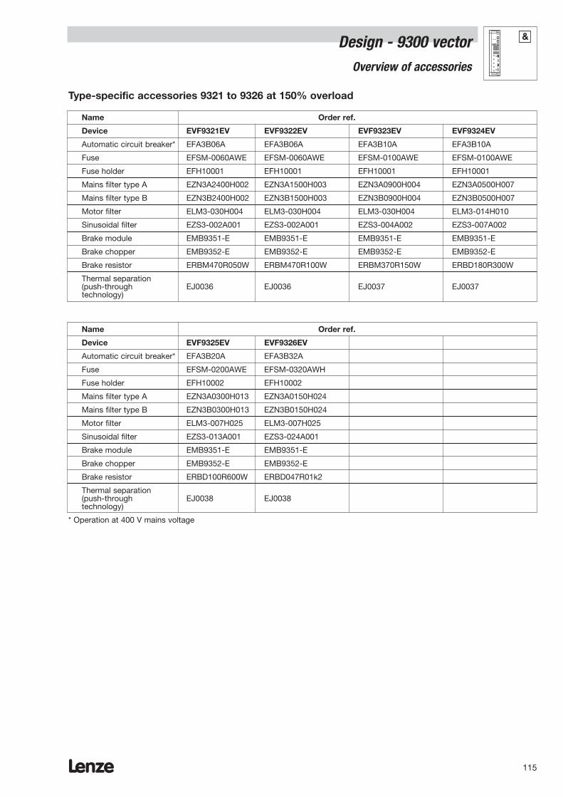
Lenze 115
Design - 9300 vector Overview of accessories
Name Order ref.
Device EVF9321EV EVF9322EV EVF9323EV EVF9324EV
Automatic circuit breaker* EFA3B06A EFA3B06A EFA3B10A EFA3B10A
Fuse EFSM-0060AWE EFSM-0060AWE EFSM-0100AWE EFSM-0100AWE
Fuse holder EFH10001 EFH10001 EFH10001 EFH10001
Mains filter type A EZN3A2400H002 EZN3A1500H003 EZN3A0900H004 EZN3A0500H007
Mains filter type B EZN3B2400H002 EZN3B1500H003 EZN3B0900H004 EZN3B0500H007
Motor filter ELM3-030H004 ELM3-030H004 ELM3-030H004 ELM3-014H010
Sinusoidal filter EZS3-002A001 EZS3-002A001 EZS3-004A002 EZS3-007A002
Brake module EMB9351-E EMB9351-E EMB9351-E EMB9351-E
Brake chopper EMB9352-E EMB9352-E EMB9352-E EMB9352-E
Brake resistor ERBM470R050W ERBM470R100W ERBM370R150W ERBD180R300W
Thermal separation(push-through EJ0036 EJ0036 EJ0037 EJ0037technology)
Type-specific accessories 9321 to 9326 at 150% overload
Name Order ref.
Device EVF9325EV EVF9326EV
Automatic circuit breaker* EFA3B20A EFA3B32A
Fuse EFSM-0200AWE EFSM-0320AWH
Fuse holder EFH10002 EFH10002
Mains filter type A EZN3A0300H013 EZN3A0150H024
Mains filter type B EZN3B0300H013 EZN3B0150H024
Motor filter ELM3-007H025 ELM3-007H025
Sinusoidal filter EZS3-013A001 EZS3-024A001
Brake module EMB9351-E EMB9351-E
Brake chopper EMB9352-E EMB9352-E
Brake resistor ERBD100R600W ERBD047R01k2
Thermal separation(push-through EJ0038 EJ0038technology)
* Operation at 400 V mains voltage
&

Lenze116
Design - 9300 vector Overview of accessories
Name Order ref.
Device EVF9331EV EVF9332EV EVF9333EV
Mains filter type A EZN3A0030H110 EZN3A0022H150 EZN3A0017H200
Mains filter type B EZN3B0030H110 EZN3B0022H150 EZN3B0017H200
Mains choke ELN3-0027H105 ELN3-0022H130 ELN3-0017H170
Motor filter on request on request on request
Sinusoidal filter on request on request on request
Brake module EMB9351-E EMB9351-E EMB9351-E
Brake chopper EMB9352-E (2 x) EMB9352-E (3 x) EMB9352-E (3 x)
Brake resistor ERBD018R03k0 (2 x) ERBD022R03k0 (3 x) ERBD018R03k0 (3 x)
Thermal separation EJ0010 EJ0009 EJ0009
Name Order ref.
Device EVF9327EV EVF9328EV EVF9329EV EVF9330EV
Mains filter type A EZN3A0110H030 EZN3A0080H042 EZN3A0055H060 EZN3A0037H090
Mains filter type B EZN3B0110H030 EZN3B0080H042 EZN3B0055H060 EZN3B0037H090
Mains choke ELN3-0088H035 ELN3-0075H045 ELN3-0055H055 ELN3-0038H085
Motor filter ELM3-004H055 ELM3-004H055 on request on request
Sinusoidal filter on request on request on request on request
Brake module EMB9351-E EMB9351-E EMB9351-E EMB9351-E
Brake chopper EMB9352-E EMB9352-E EMB9352-E EMB9352-E (2 x)
Brake resistor ERBD033R02k0 ERBD022R03k0 ERBD018R03k0 ERBD022R03k0 (2 x)
Thermal separation EJ0011 EJ0011 EJ0011 EJ0010
Type-specific accessories 9327EV to 9333EV at 150% overload
&
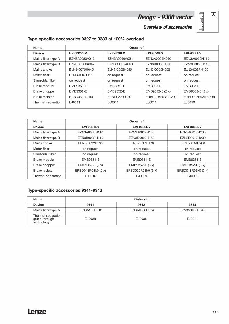
Lenze 117
Design - 9300 vector Overview of accessories
Name Order ref.
Device EVF9331EV EVF9332EV EVF9333EV
Mains filter type A EZN3A0030H110 EZN3A0022H150 EZN3A0017H200
Mains filter type B EZN3B0030H110 EZN3B0022H150 EZN3B0017H200
Mains choke ELN3-0022H130 ELN3-0017H170 ELN3-0014H200
Motor filter on request on request on request
Sinusoidal filter on request on request on request
Brake module EMB9351-E EMB9351-E EMB9351-E
Brake chopper EMB9352-E (2 x) EMB9352-E (3 x) EMB9352-E (3 x)
Brake resistor ERBD018R03k0 (2 x) ERBD022R03k0 (3 x) ERBD018R03k0 (3 x)
Thermal separation EJ0010 EJ0009 EJ0009
Name Order ref.
Device EVF9327EV EVF9328EV EVF9329EV EVF9330EV
Mains filter type A EZN3A0080A042 EZN3A0060A054 EZN3A0055H060 EZN3A0030H110
Mains filter type B EZN3B0080A042 EZN3B0055A060 EZN3B0055H060 EZN3B0030H110
Mains choke ELN3-0075H045 ELN3-0055H055 ELN3-0055H055 ELN3-0027H105
Motor filter ELM3-004H055 on request on request on request
Sinusoidal filter on request on request on request on request
Brake module EMB9351-E EMB9351-E EMB9351-E EMB9351-E
Brake chopper EMB9352-E EMB9352-E EMB9352-E (2 x) EMB9352-E (2 x)
Brake resistor ERBD033R02k0 ERBD022R03k0 ERBD018R03k0 (2 x) ERBD022R03k0 (2 x)
Thermal separation EJ0011 EJ0011 EJ0011 EJ0010
Type-specific accessories 9327 to 9333 at 120% overload
Name Order ref.
Device 9341 9342 9343
Mains filter type A EZN3A120H012 EZN3A0088H024 EZN3A0055H045
Thermal separation(push-through EJ0038 EJ0038 EJ0011technology)
Type-specific accessories 9341-9343
&
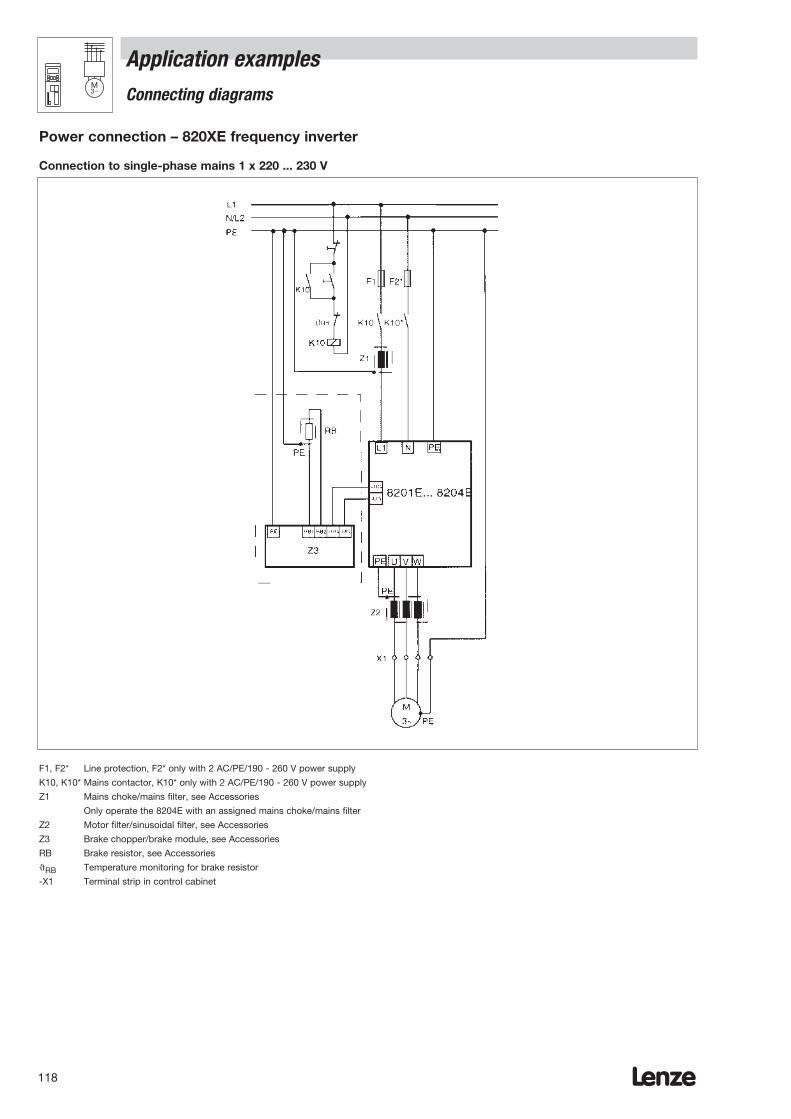
Lenze118
Power connection – 820XE frequency inverter
Connection to single-phase mains 1 x 220 ... 230 V
F1, F2* Line protection, F2* only with 2 AC/PE/190 - 260 V power supply
K10, K10* Mains contactor, K10* only with 2 AC/PE/190 - 260 V power supply
Z1 Mains choke/mains filter, see Accessories
Only operate the 8204E with an assigned mains choke/mains filter
Z2 Motor filter/sinusoidal filter, see Accessories
Z3 Brake chopper/brake module, see Accessories
RB Brake resistor, see Accessories
RB Temperature monitoring for brake resistor
-X1 Terminal strip in control cabinet
Connecting diagrams
Application examplesM3~

Lenze 119
Power connection - 821X, 824X and 822X frequency inverters
Connection to three-phase mains 3 x 400 ... 460 V/480 V
F1, F2, F3 Line protection
K10 Mains contactor
Z1 Mains choke/mains filter, see Accessories
Only operate the 8214E and 8221 to 8227 with an assigned
mains choke/mains filter
Z2 Motor filter/sinusoidal filter, see Accessories
Z3 Brake chopper/brake module, see Accessories
RB Brake resistor, see Accessories
RB Temperature monitoring for brake resistor
-X1 Terminal strip in control cabinet
Application examplesConnecting diagrams
M3~
8221...27
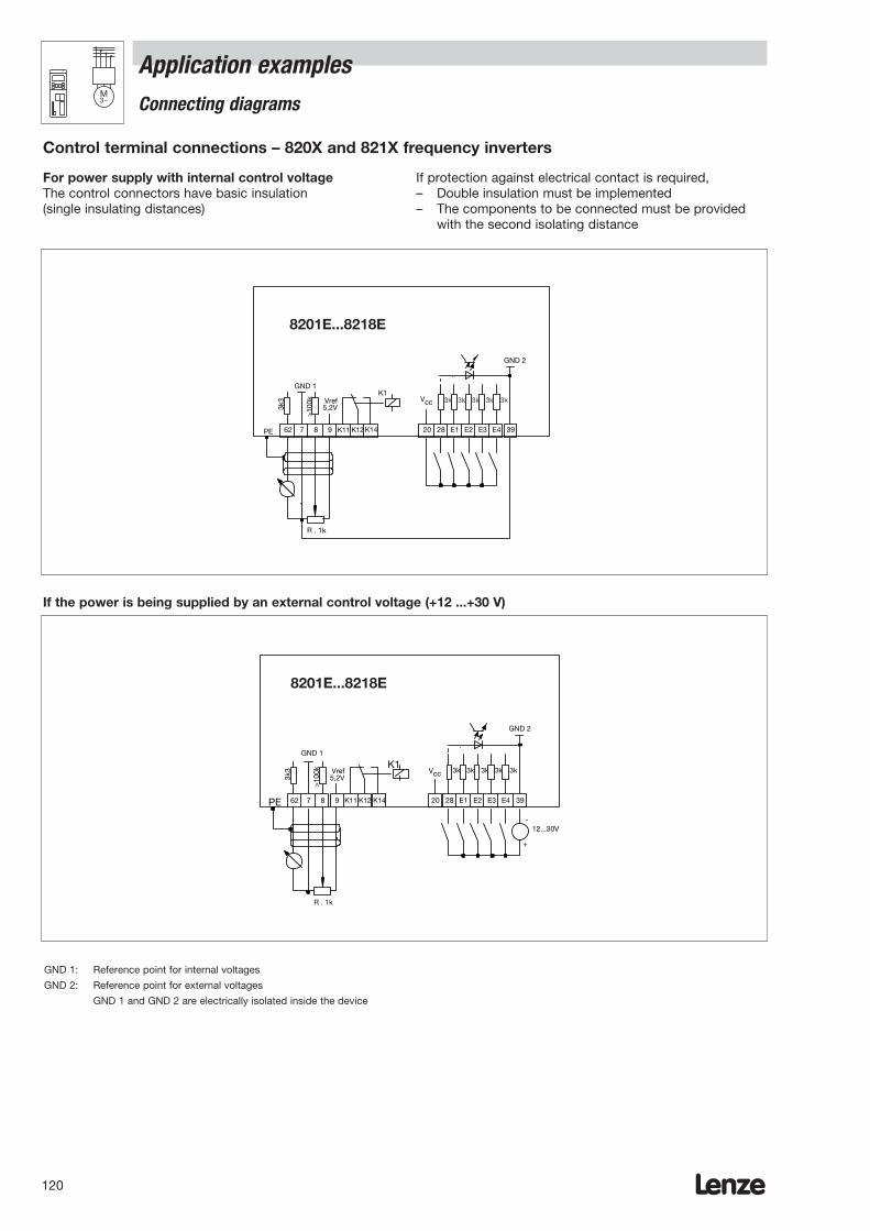
Lenze120
For power supply with internal control voltageThe control connectors have basic insulation (single insulating distances)
GND 1: Reference point for internal voltages
GND 2: Reference point for external voltages
GND 1 and GND 2 are electrically isolated inside the device
If the power is being supplied by an external control voltage (+12 ...+30 V)
If protection against electrical contact is required,– Double insulation must be implemented– The components to be connected must be provided
with the second isolating distance
3k 3k3k3k3k
62 7 8 9 K11 K12 K14
GND 2
K1GND 1
5,2VVref
3k3
>10
0k
R . 1k
20 28 E1 E2 E3 E4 39PE
82XX
Vcc
62 7 8 9 K11 K12 K14
3k 3k3k3k3k
GND 2
GND 1
5,2VVref
3k3
>10
0k
12...30V
R . 1k
+
-
20 28 E1 E2 E3 E4 39PE
K1
82XX
Vcc
Connecting diagrams
Application examplesM3~
Control terminal connections – 820X and 821X frequency inverters
8201E...8218E
8201E...8218E

Lenze 121
GND 1: Reference point for internal voltages
GND 2: Reference point for external voltages
GND 1 and GND 2 are electrically isolated inside the device
If the power is being supplied by an external control voltage (+12 ... +30 V)
62 7 8 9 K11 K12 K14
GND 1
5,2VVref
3k3
>10
0k824XE, 822XE
R ≥ 1k
PE K21K22 K24
3k 3k3k3k3kVcc15V
GND 2
20 28 E1 E2 E3 E4 39 +PTC -PTC
PTC
Sx
K2K1
62 7 8 9 K11 K12 K14
K1GND 1
5,2VVref
3k3
>10
0k
824XE, 822XE
R ≥ 1k
PE K21 K22 K24
K23k 3k3k3k3k
Vcc15V
GND 2
20 28 E1 E2 E3 E4 39
12...30V+
-
+PTC -PTC
PTC
Sx
Application examplesConnecting diagrams
M3~
For power supply with internal control voltageThe control current terminals have dual basic insulation.
Control terminal connections – 824X and 822X frequency inverters

Lenze122

Lenze 123
Power connection - 9300 vector frequency inverters
Connection to three-phase mains 3 x 400 ... 460 V/480 V
F1, F2, F3 Line protection
K10 Mains contactor
Z1 Mains choke/mains filter, see Accessories
Only operate 9327-9333 inverters with
an assigned mains choke/mains filter
Z2 Motor filter/sinusoidal filter, see Accessories
Z3 Brake chopper/brake module, see Accessories
RB Brake resistor, see Accessories
RB Temperature monitoring for brake resistor
-X1 Terminal strip in control cabinet
Application examplesConnecting diagrams
M3~
EVF93XX

Lenze124
Notes about control cablesThe frequency inverters have a number of digital andanalog inputs and outputs. An internal or external controlvoltage can be used to supply them with power. The control current terminals have basic insulation. If protection against electrical contact is required,– Double insulation must be implemented– The components to be connected must be providedwith the second isolating distanceThe following connecting diagrams should be used for thepurposes of wiring:
With internal control voltage With external control voltage
Digital inputs and outputs Digital inputs and outputsAnalog inputs and outputs Analog inputs and outputs
Notes about wiringConnect the control cables to screw terminals X5 and X6on the front of the drive controller. Torque: 0.5 -0.6 NmShielding the control cables:– The PE connection is made via the shield sheet shown
(included in the assembly kit). Do not use it for the purposes of strain relief!
– Using a screw, connect the shield sheet on the drive controller with PE.
A328 E1 E2 E3 E4 E5 A1 A2 59
_
39
22k 10R
R L
GND 2
+
QSP
JOG TRIP- Set/Reset
TRIP
RDY|nist| < nx
Mmax
3k 3k 3k 3k 3k 3k 3k
50m
A
50m
A
50m
A
50m
A
A4
RFR
X5
+_=
=
24V
24V
Prozessor-board
93XX
GND 2
Application examplesConnecting diagrams
M3~
External control voltage
Internal control voltage
Example: Assignment of input and output terminals
A328 E1 E2 E3 E4 E5 A1 A2 5939
22k 10R
R L
GND 2
QSP TRIP- Set/Reset
RDY|nist| < nx
FIXED1
3k 3k 3k 3k 3k 3k 3k
A4
RFR
X5
50m
A
50m
A
50m
A
50m
A+_
24V
=
Prozessor-board
JOG
93XX
Mmax
GND 2
Connecting diagrams for 9300 vector frequency inverters
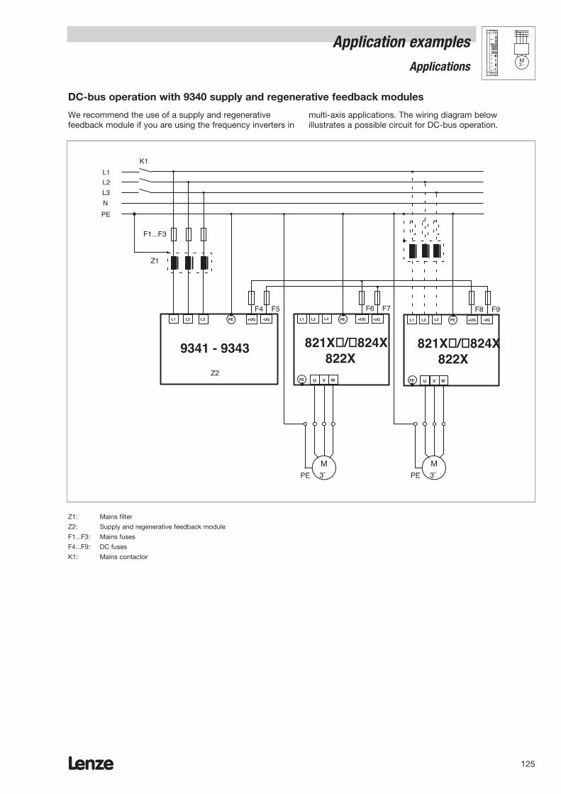
Lenze 125
Application examplesApplications
M3~
We recommend the use of a supply and regenerativefeedback module if you are using the frequency inverters in
multi-axis applications. The wiring diagram below illustrates a possible circuit for DC-bus operation.
DC-bus operation with 9340 supply and regenerative feedback modules
L3
N
PE
L1
L2
L1 L2 L3
F1...F3
9341 - 9343
PE +UG -UG
Z1
K1
U V W
M3˜PE
L1 L2 L3
821X/824X822X
PE +UG -UG
PE
U V W
M3˜PE
L1 L2 L3
821X/824X822X
PE +UG -UG
PE
F4 F5 F6 F7 F8 F9
Z2
Z1: Mains filter
Z2: Supply and regenerative feedback module
F1...F3: Mains fuses
F4...F9: DC fuses
K1: Mains contactor
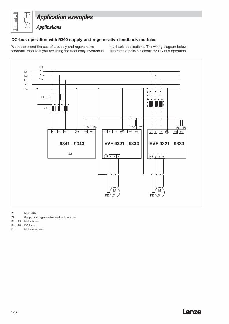
Lenze126
Application examplesApplications
M3~
We recommend the use of a supply and regenerativefeedback module if you are using the frequency inverters in
multi-axis applications. The wiring diagram belowillustrates a possible circuit for DC-bus operation.
DC-bus operation with 9340 supply and regenerative feedback modules
L3
N
PE
L1
L2
L1 L2 L3
F1...F3
9341 - 9343
PE +UG -UG
Z1
K1
U V W
M3˜PE
L1 L2 L3
EVF 9321 - 9333
PE +UG -UG
PE
U V W
M3˜PE
L1 L2 L3
EVF 9321 - 9333
PE +UG -UG
PE
F4 F5 F6 F7 F8 F9
Z2
Z1 Mains filter
Z2 Supply and regenerative feedback module
F1. . .F3: Mains fuses
F4. . .F9: DC fuses
K1: Mains contactor
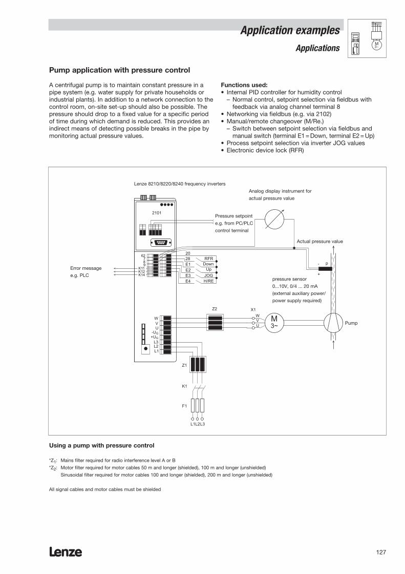
Lenze 127
Application examplesApplications
M3~
A centrifugal pump is to maintain constant pressure in apipe system (e.g. water supply for private households orindustrial plants). In addition to a network connection to thecontrol room, on-site set-up should also be possible. Thepressure should drop to a fixed value for a specific periodof time during which demand is reduced. This provides anindirect means of detecting possible breaks in the pipe bymonitoring actual pressure values.
Functions used:• Internal PID controller for humidity control
– Normal control, setpoint selection via fieldbus with feedback via analog channel terminal 8
• Networking via fieldbus (e.g. via 2102)• Manual/remote changeover (M/Re.)
– Switch between setpoint selection via fieldbus andmanual switch (terminal E1 = Down, terminal E2 = Up)
• Process setpoint selection via inverter JOG values• Electronic device lock (RFR)
Pump application with pressure control
Using a pump with pressure control
*Z1: Mains filter required for radio interference level A or B
*Z2: Motor filter required for motor cables 50 m and longer (shielded), 100 m and longer (unshielded)
Sinusoidal filter required for motor cables 100 and longer (shielded), 200 m and longer (unshielded)
All signal cables and motor cables must be shielded
K14K12K11
RFRDown
JOG
M3~
Frequenzumrichter 8210/8220/8240
Druck-Sollwertz. B. von PC/SPSBedienterminal
Störungsmeldungz. B. SPS
analoges Anzeigeinstrumentfür Druck-Istwert
Druck-Istwert
-
+
p
Drucksensor0 ... 10V, 0/4 ... 20mA(externe Hilfsenergie/
Versorgung erforderlich)
Pumpe
WVU
Z1
K1
F1
Z2
L1L2L3
Up
H/RE
28E1
E3E2
E4
2062
789
X1
2101
WVUG-UG+U
L1L2L3
Lenze 8210/8220/8240 frequency inverters
Analog display instrument for
actual pressure value
Actual pressure value
Error message
e.g. PLCpressure sensor
0...10V, 0/4 ... 20 mA
(external auxiliary power/
power supply required)
Pump
Pressure setpoint
e.g. from PC/PLC
control terminal
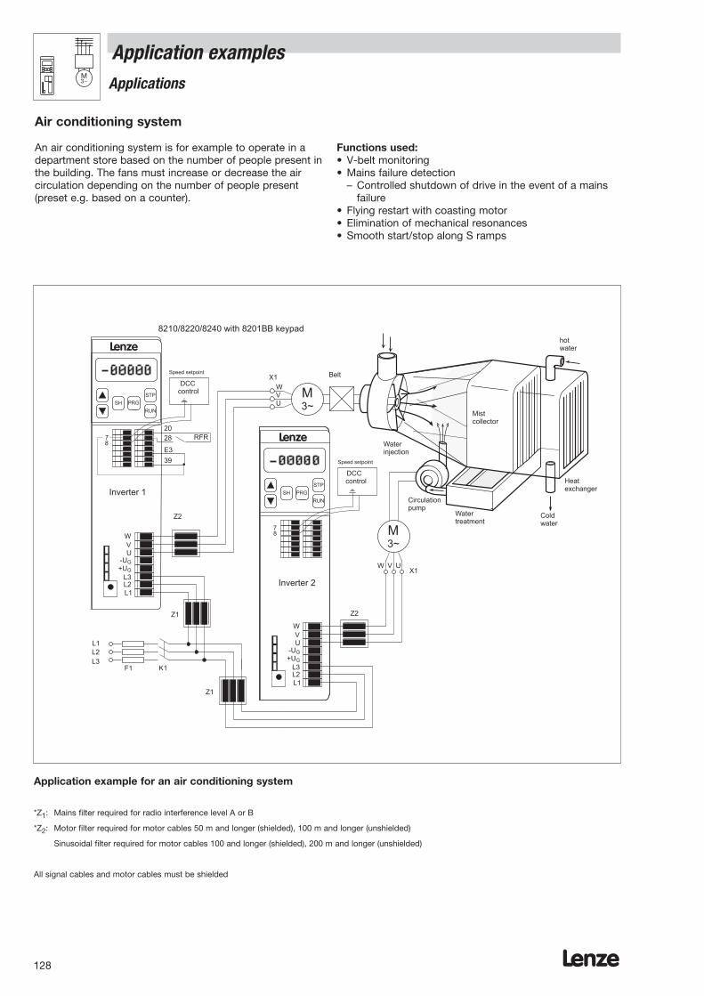
Lenze128
Application examplesApplications
M3~
An air conditioning system is for example to operate in adepartment store based on the number of people present inthe building. The fans must increase or decrease the aircirculation depending on the number of people present(preset e.g. based on a counter).
Functions used:• V-belt monitoring• Mains failure detection
– Controlled shutdown of drive in the event of a mains failure
• Flying restart with coasting motor• Elimination of mechanical resonances• Smooth start/stop along S ramps
Air conditioning system
Application example for an air conditioning system
*Z1: Mains filter required for radio interference level A or B
*Z2: Motor filter required for motor cables 50 m and longer (shielded), 100 m and longer (unshielded)
Sinusoidal filter required for motor cables 100 and longer (shielded), 200 m and longer (unshielded)
All signal cables and motor cables must be shielded
M3~
M3~
W
W
V
V
U
UX1
X1
Z1
WVUG-UG+U
Z1
Z2
78
DCCcontrol
DCCcontrol
Z2
78
RUN
PRG
STP
SH
RUN
PRG
STP
SH
K1F1
L1
L1
L2
L2
L3
L3
WVUG-UG+U
L1L2L3
E3
20RFR
39
28
Belt
Mistcollector
Circulationpump
-
Watertreatment
-
Heatexchanger
Coldwater
hotwater
Waterinjection
Speed setpoint
Speed setpoint
8210/8220/8240 with 8201BB keypad
Inverter 1
Inverter 2
Lenze
Lenze

Lenze 129
Application examplesApplications
M3~
The water level in a water tank must remain constant.Depending on the amount of water drained, the feedpumps must adjust the speed and refill the tank with water.
Functions used:• Internal PID controller for level control
– Normal control, analog setpoint selection via terminal8 with feedback via analog channel E1 with plug-inmodule 8279
Pump application with level control
Using a pump with level control
*Z1: Mains filter required for radio interference level A or B
*Z2: Motor filter required for motor cables 50 m and longer (shielded), 100 m and longer (unshielded)
Sinusoidal filter required for motor cables 100 and longer (shielded), 200 m and longer (unshielded)
All signal cables and motor cables must be shielded
M3~
Füllstands-Sollwert0 ... 10V, 0/4 ... 20mA
Förderpumpe
WVU
Z1
K1
F1
Z2
L1 L2 L3
78
+
-39
E1
20
28 RFR
8279
Zufluß
Abfluß
Wasserbehälter
X1
RUN
PRG
STP
SH
Lenze
Drucksensor0 ... 10V, 0/4 ... 20mA(externe Hilfsenergie/Versorgung erforderlich)
WVUG-UG+U
L1L2L3
Level setpoint
0 ... 10 V, 0/4 ... 20 mA
Pressure sensor
0 ...10 V, 0/4 ... 20 mA (external
auxiliary power/power supply
required)
Feed pump
Inlet
Outlet
Water tank

Lenze130
Application examplesApplications
M3~
Applications in which the drive should repeatedly turn aspecific number of revolutions. This type of application isused for example to move unit loads on a conveyor beltsequentially or for dosing specific amounts repeatedly onworm conveyors.The conveyor speed and path or dosing speed and amountare controlled independently of one another via the twoanalog inputs.
The execution of a step is started via a digital input.
Functions used:– Optimum acceleration ramp generation– Speed measurement– Brake control
Step control
Dosierantrieb
Förderantrieb
Basic structure of a step controller for a bulk material filling station
9300 vector frequency inverter
Conveyor drive
Dosing drive
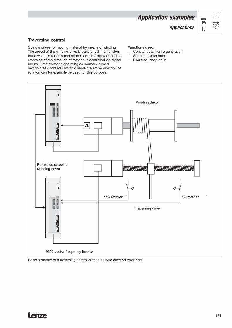
Lenze 131
Application examplesApplications
M3~
Spindle drives for moving material by means of winding.The speed of the winding drive is transferred in an analoginput which is used to control the speed of the winder. Thereversing of the direction of rotation is controlled via digitalinputs. Limit switches operating as normally closedswitch/break contacts which disable the active direction ofrotation can for example be used for this purpose.
Functions used:– Constant path ramp generation– Speed measurement– Pilot frequency input
Traversing control
Basic structure of a traversing controller for a spindle drive on rewinders
Wickelantrieb
Führungssollwert(Wickelantrieb)
RechtslaufLinkslauf
Verlegeantrieb
9300 vector frequency inverter
Winding drive
Reference setpoint(winding drive)
ccw rotation cw rotation
Traversing drive

Lenze132
Application examplesApplications
M3~
Integrating the drive controller into a drive system.The drive is controlled by reading in the pilot frequencysetpoint via input X9. This value is then evaluated and thespeed of the drive is adapted to the process based on theresult of the evaluation.An internal additional setpoint can also be activated viadigital input E3.Unlike in the pilot frequency slave configuration (bus), theevaluated control setpoint is forwarded via pilot frequency
output X10. This means that changes in the evaluationalso affect subsequent drives.
Functions used:– Pilot frequency input– Analysis of gearbox ratio– Analog/digital gearbox ratio trimming– Pilot frequency ramp function generator
Pilot frequency - Slave (cascade)
M
HauptantriebLeitfrequenz - Master
Hauptsollwert
M
Rohmaterial
M MM
Aufheizen Aufrauhen der Oberfläche
FolgeantriebeLeitfrequenz - Slave (Schiene/Kaskade)
Leitfrequenz
Basic structure of a pilot frequency network for textile machinery
9300 vector frequency inverter
Warm-up Napping
Pilot frequency
Main setpoint
Raw material
Slave drivePilot frequency-slave (rail/cascade)
Main drivePilot frequency-master

Lenze 133
Application examplesApplications
M3~
Winding drives with dancer position control. Unlike thedancer position control configuration with external diameterdetection, in this type of application, the diameter iscalculated internally.A pilot frequency signal is sent for pilot control of the drivewith the system/material speed. On the basis of the actualposition of the dancing roller, the dancer position controllergenerates a correction signal which is added to the pilotcontrol signal. This results in a circumferential speedsetpoint which, when multiplied by 1/D, provides the speedsetpoint.
The reel diameter is calculated using the signals for theline speed and the winding speed. Each time the reelchanges, the new initial diameter can be loaded.
Functions used:– Pilot frequency input– Dancer position control– Diameter calculation
Dancer position control (internal diameter calculator)
Basic structure of a dancer position controller with calculation of diameter via the internal diameter calculator
M
M
AufwicklerTänzerVLinie
R-Lauf
L-Lauf
Liniengeschwindigkeit
Tänzerlage
Anfangs-durchmesser
Durchmesser-Preset
9300 vector frequency inverter
DancerV Line Winder
cw rot.
ccw rot.
Dancer position
Line speed
Diameterpre-set
Initial diameter
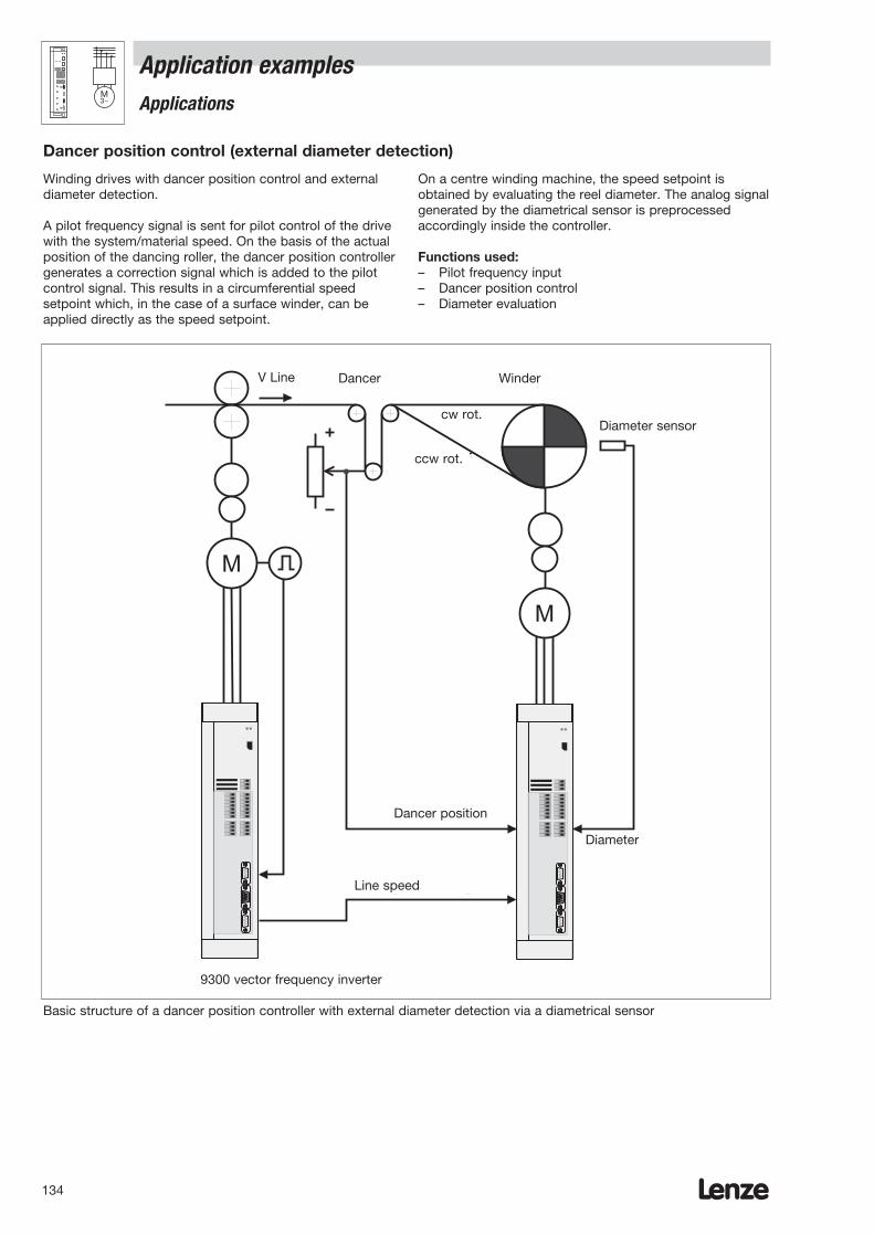
Lenze134
Application examplesApplications
M3~
Winding drives with dancer position control and externaldiameter detection.
A pilot frequency signal is sent for pilot control of the drivewith the system/material speed. On the basis of the actualposition of the dancing roller, the dancer position controllergenerates a correction signal which is added to the pilotcontrol signal. This results in a circumferential speedsetpoint which, in the case of a surface winder, can beapplied directly as the speed setpoint.
On a centre winding machine, the speed setpoint isobtained by evaluating the reel diameter. The analog signalgenerated by the diametrical sensor is preprocessedaccordingly inside the controller.
Functions used:– Pilot frequency input– Dancer position control– Diameter evaluation
Dancer position control (external diameter detection)
M
M
AufwicklerTänzerVLinie
Durchmesser-sensor
R-Lauf
L-Lauf
Liniengeschwindigkeit
Tänzerlage
Durchmesser
Basic structure of a dancer position controller with external diameter detection via a diametrical sensor
9300 vector frequency inverter
DancerV Line Winder
cw rot.
ccw rot.
Dancer position
Line speed
Diameter
Diameter sensor

Lenze 135

To: LenzeBranch/International agency
City/Postcode:
Fax number:
Lenze136
From
Company Customer no.
Street Order ref.
City/Postcode Drawer
Delivery address* Tel.
Fax
Invoice to* Delivery date
* To be completed if different from above. Date Signature
Order form
820X frequency inverter with accessories
Name Type Quantity Price Type Quantity Price
Inverter EVF820__-E EVF820__-E
Automatic circuit breaker
Fuse
Fuse holder
Mains filter
Mains choke
RFI filter
Motor filter
Sinusoidal filter
Brake module
Name Type Quantity Price
Swivel wall fastening EJ0001
DIN rail mounting EJ0002
Fan for surface mounting EJ0003
Setpoint potentiometer ERP0001k0001W
Rotary knob for potentiometer ERZ0001
Scale for potentiometer ERZ0002
8201BB operating module EMZ8201BB
Diagnosis terminal with 2.5 m cable EMZ8272BB-V001
Diagnosis terminal with 5.0 m cable EMZ8272BB-V002
Diagnosis terminal with 10 m cable EMZ8272BB-V003
LECOM A/B module EMF2102IB-V001
LECOM B module EMF2102IB-V002
Level converter for LECOM B EMF2101IB
PC system cable LECOM A/B EWL0001
LECOM LI module EMF2102IB-V003
Optical fibre adapter for PLC 0...40m EMF2125IB
Power supply for 2125 EJ0013
InterBus-S module EMF2111IB
System bus module EMF2171IB

To: LenzeBranch/International agency
City/Postcode:
Fax number:
Lenze 137
Order form
From
Company Customer no.
Street Order ref.
City/Postcode Drawer
Delivery address* Tel.
Fax
Invoice to* Delivery date
* To be completed if different from above. Date Signature
821X frequency inverter with accessories
Name Type Quantity Price Type Quantity Price
Inverter EVF821__-E EVF821__-E
Automatic circuit breaker
Fuse
Fuse holder
Mains choke
RFI filter
Motor filter
Sinusoidal filter
Brake module
Brake chopper
Brake resistor
Name Type Quantity Price
Swivel wall fastening EJ0001
DIN rail mounting EJ0002
Thermal separation EJ0003
Setpoint potentiometer ERPD0001k0001W
Rotary knob for potentiometer ERZ0001
Scale for potentiometer ERZ0002
8201BB operating module EMZ8201BB
Diagnosis terminal with 2.5 m cable EMZ8272BB-V001
Diagnosis terminal with 5.0 m cable EMZ8272BB-V002
Diagnosis terminal with 10 m cable EMZ8272BB-V003
LECOM A/B module EMF2102IB-V001
LECOM B module EMF2102IB-V002
Level converter for LECOM B EMF2101IB
PC system cable LECOM A/B EWL0001
LECOM LI module EMF2102IB.V003
Optical fibre adapter for PLC 0...40 m EMF2125IB
Power supply for 2125 EJ0013
InterBus-S module EMF2111IB
System bus module EMF2171IB

Lenze138
To:: LenzeBranch/International agency
City/Postcode:
Fax number:
Order form
From
Company Customer no.
Street Order ref.
City/Postcode Drawer
Delivery address* Tel.
Fax
Invoice to* Delivery date
* To be completed if different from above. Date Signature
824X, 822X frequency inverter with accessories
Name Type Quantity Price Type Quantity Price
Inverter EVF82__-E EVF822__-E
Automatic circuit breaker
Fuse
Fuse holder
Mains filter A
Mains filter B
Motor filter
Sinusoidal filter
Brake chopper
Brake resistor
Brake module
Thermal separation
Name Type Quantity Price
Setpoint potentiometer ERPD0001k0001W
Rotary knob for potentiometer ERZ0001
Scale for potentiometer ERZ0002
8201BB operating module EMZ8201BB
Diagnosis terminal with 2.5 m cable EMZ8272BB-V001
Diagnosis terminal with 5.0 m cable EMZ8272BB-V002
Diagnosis terminal with 10 m cable EMZ8272BB-V003
LECOM A/B module EMF2102IB-V001
LECOM B module EMF2102IB-V002
Level converter for LECOM B EMF2101IB
PC system cable LECOM A/B EWL0001
LECOM LI module EMF2102IB-V003
Optical fibre adapter for PLC 0...40 m EMF2125IB
Power supply for 2125 EJ0013
InterBus-S module EMF2111IB
System bus module EMF2171IB
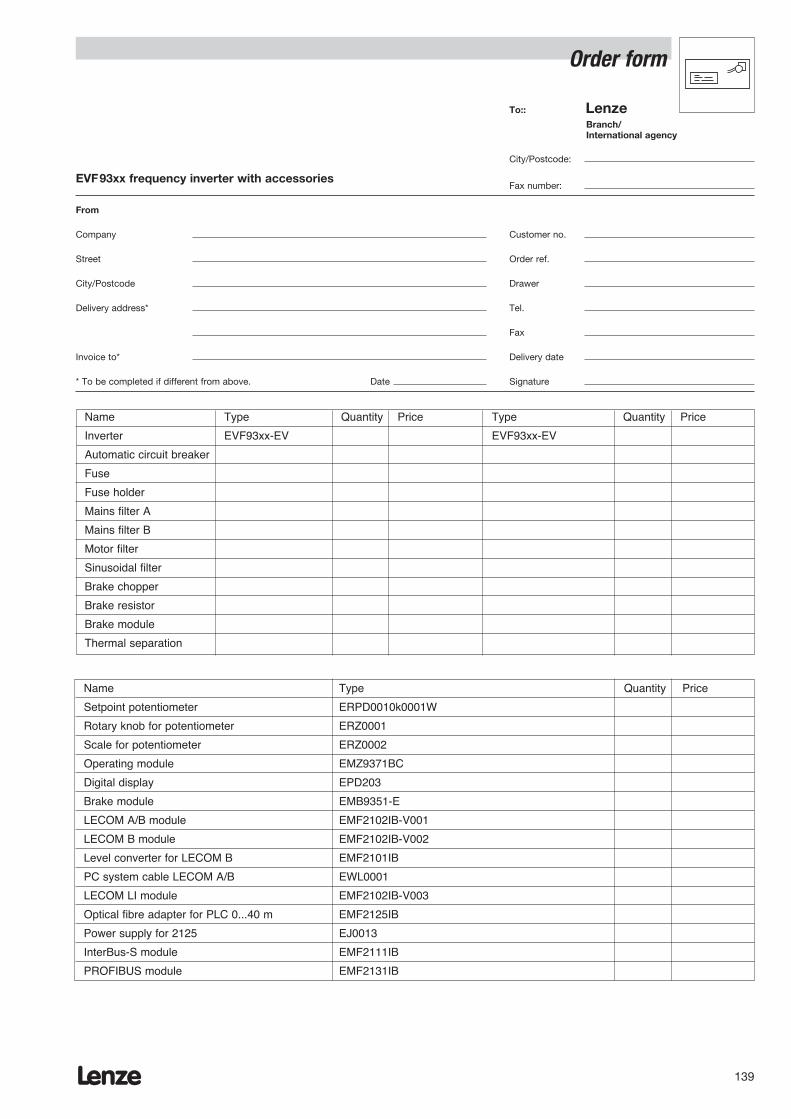
Lenze 139
Order form
To:: LenzeBranch/International agency
City/Postcode:
Fax number:
From
Company Customer no.
Street Order ref.
City/Postcode Drawer
Delivery address* Tel.
Fax
Invoice to* Delivery date
* To be completed if different from above. Date Signature
EVF93xx frequency inverter with accessories
Name Type Quantity Price Type Quantity Price
Inverter EVF93xx-EV EVF93xx-EV
Automatic circuit breaker
Fuse
Fuse holder
Mains filter A
Mains filter B
Motor filter
Sinusoidal filter
Brake chopper
Brake resistor
Brake module
Thermal separation
Name Type Quantity Price
Setpoint potentiometer ERPD0010k0001W
Rotary knob for potentiometer ERZ0001
Scale for potentiometer ERZ0002
Operating module EMZ9371BC
Digital display EPD203
Brake module EMB9351-E
LECOM A/B module EMF2102IB-V001
LECOM B module EMF2102IB-V002
Level converter for LECOM B EMF2101IB
PC system cable LECOM A/B EWL0001
LECOM LI module EMF2102IB-V003
Optical fibre adapter for PLC 0...40 m EMF2125IB
Power supply for 2125 EJ0013
InterBus-S module EMF2111IB
PROFIBUS module EMF2131IB

To: LenzeBranch/International agency
City/Postcode:
Fax number:
Lenze140
Order form
From
Company Customer no.
Street Order ref.
City/Postcode Drawer
Delivery address* Tel.
Fax
Invoice to* Delivery date
* To be completed if different from above. Date Signature
934XE supply/feedback module
Name Type Quantity Price Type Quantity Price
S/F module EMB934__-E EMB934__-E
Fuse
Fuse holder
Mains filter A
Thermal separation

Lenze 141


Lenze 143