framestart fsm reference manualchapter 0preface about this manual this reference guide for the...
TRANSCRIPT
i
FrameStart™ FSMMay 200234-00299.E
Copyright Notice Copyright © 2002 Verilink Corporation. All rights reserved. No part of this publication may bereproduced, transmitted, transcribed, stored in a retrieval system, or translated into any languagein any form by any means without the written permission of Verilink.
Manual Reorder # 34-00299.E
May 2002
Trademarks Verilink® is a registered trademark Verilink Corporation. FrameStart™ and ServiceAware™are both trademarks of Verilink Corporation.
All other brand and product names used herein are trademarks or registered trademarks of theirrespective manufacturers.
Documentation Disclaimer
This document does not create any express or implied warranty about Verilink or about its prod-ucts or services. Verilink’s sole warranty is contained in its product warranty. The end-user doc-umentation is shipped with Verilink’s products and constitutes the sole specifications referred toin the product warranty. Verilink has made reasonable efforts to verify that the information con-tained herein is accurate, but Verilink assumes no responsibility for its use or for any infringe-ment of patents or other rights of third parties that may result. The customer is solelyresponsible for verifying the suitability of Verilink’s products for its use. Specifications are sub-ject to change without notice.
Warranty Verilink's product warranty is included at the back of this document.
FCC Requirements This equipment has been tested and found to comply with the limits for a Class A digital device,pursuant to Part 15 of FCC Rules. These limits are designed to provide reasonable protectionagainst harmful interference when the equipment is operated in a commercial environment. Thisequipment generates, uses, and can radiate radio frequency energy and if not installed and usedin accordance with the instruction manual, may cause harmful interference to radio communica-tions. Operation of this equipment in a residential area is likely to cause harmful interference inwhich case the user is required to correct the interference at his own expense. This device mustalso accept any interference received, including interference that may cause undesired operation.
WARNING: For use only with a certified Class 2 power supply. See Power Source in Appendix A, Specifications.
WARNING: Changes or modifications to this unit not expressly approved by the party responsible for compliance could void the user’s authority to operate the equipment.
This equipment complies with Part 68 of the FCC Rules. On the rear or bottom of the unit is alabel that contains the FCC registration number and other information. If requested, provide thisinformation to the telephone company.
1 All direct connections to the network lines must be made using standard plugs and jacks (compliant with Part 68). The table below presents a list of applicable registration jack USOCs, facility interface codes (FICs), and service order codes (SOCs). These are required when ordering service from the telco.
2 If the unit appears to be malfunctioning, it should be disconnected from the network lines until the source of trouble is determined to be your equipment or the telephone line. If your equipment needs repair, it should not be reconnected until it is repaired.
Port ID REN/SOC FIC USOC
1.544 Mbps SF1.544 Mbps SF, B8ZS1.544 Mbps ANSI ESF1.544 Mbps ANSI ESF, B8ZS
6.0F 04DU9-BN 04DU9-DN 04DU9-1KN04DU9-1SN
RJ-48C jack
ii F r a m e S t a r t F S M
3 The unit has been designed to prevent harm to the network. If the telephone company finds that the equipment is exceeding tolerable parameters, it can temporarily disconnect service. In this case, the telephone company will give you advance notice, if possible.
4 No customer is authorized to repair this equipment, regardless of warranty status.
5 If the telephone company alters its equipment in a manner that will affect the use of this device, it must give you warning so that you have the opportunity for uninterrupted service. You will be advised of your right to file a complaint with the FCC.
6 If the equipment malfunctions, all repairs should be performed by our company or an authorized agent. It is the responsibility of users requiring service to report the need for service to our company or to one of our authorized agents.
Canadian Emissions Requirements
This digital apparatus does not exceed the Class A limits for radio noise emissions from digitalapparatus set out in the Radio Interference Regulations of the Canadian Department of Commu-nications.
Le présent appareil numérique n’émet pas de bruits radioélectriques dépassant les limites appli-cables aux appareils numériques (de la class A) prescrites dans le Règlement sur le brouillageradioélectrique edicté par le ministère des Communications du Canada.
Safety Precautions When handling this equipment, follow these basic safety precautions to reduce the risk of elec-tric shock and injury:
• Follow all warnings and instructions marked on the product and in the manual.
• Unplug the hardware from the wall outlet before cleaning. Do not use liquid cleaners or aerosol clean-ers. Use a slightly damp cloth for cleaning.
• Do not place this product on an unstable cart, stand, or table. It may fall, causing serious damage tothe product.
• Slots in the unit are provided for ventilation to protect it from overheating. These openings must notbe blocked or covered. Never place this product near a radiator or heat register.
• This product should be operated only from the type of power source indicated on the marking labeland manual. If you are unsure of the type of power supply you are using, consult your dealer or localpower company.
• Do not allow anything to rest on the power cord. Do not locate this product where the cord interfereswith the free movement of people.
• Do not overload wall outlets and extension cords, as this can result in fire or electric shock.
• Never push objects of any kind into the unit. They may touch dangerous voltage points or short outparts that could result in fire or electric shock. Never spill liquid of any kind on this equipment.
• Unplug the equipment from the wall outlet and refer servicing to qualified service personnel under thefollowing conditions:
• When the power supply cord or plug is damaged or frayed.
• If liquid has been spilled into the product.
• If the product has been exposed to rain or water.
• If the product has been dropped or if the housing has been damaged.
iii

iv F r a m e S t a r t F S M
Table of Contents
PrefaceAbout this Manual ................................................................................................................................ ix
Manual Organization ...................................................................................................................... ixTypographic Conventions ................................................................................................................x
Customer Service and Technical Support ...............................................................................................xSupport from Your Network Supplier ..............................................................................................xSupport from Verilink ......................................................................................................................x
Telephone ..................................................................................................................................xE-mail ...................................................................................................................................... xiInternet ..................................................................................................................................... xi
Returning a Unit to Verilink ................................................................................................................. xi
Chapter 1 About the FrameStart FSMAbout FrameStart Technology ........................................................................................................... 1-1
FSM Overview and Advantages ......................................................................................................... 1-2
Features Summary .............................................................................................................................. 1-2
Front Panel .......................................................................................................................................... 1-3
Rear Panel Connections ...................................................................................................................... 1-5Supervisory Port ........................................................................................................................... 1-510/100 Ethernet ............................................................................................................................ 1-6
Ethernet LED Indicators ........................................................................................................ 1-6Serial Interface ............................................................................................................................. 1-6Network Interface ......................................................................................................................... 1-6Power Connection ........................................................................................................................ 1-7
Power Failure ......................................................................................................................... 1-8
Chapter 2 InstallationUnpacking and Inspection .................................................................................................................. 2-1
Supplied Materials .............................................................................................................................. 2-1
Installation Wizard .............................................................................................................................. 2-2
Chapter 3 Web Server InterfaceWeb Server Interface Access .............................................................................................................. 3-1
Layout of Interface Screens ......................................................................................................... 3-2
Unit Screen ......................................................................................................................................... 3-2
Interfaces ............................................................................................................................................. 3-4
v
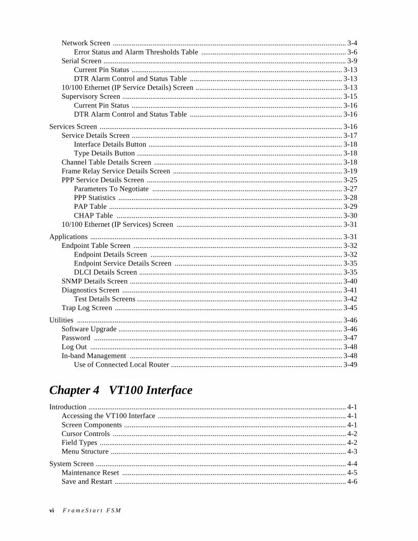
Network Screen ............................................................................................................................ 3-4Error Status and Alarm Thresholds Table ............................................................................. 3-6
Serial Screen ................................................................................................................................. 3-9Current Pin Status ................................................................................................................ 3-13DTR Alarm Control and Status Table ................................................................................. 3-13
10/100 Ethernet (IP Service Details) Screen .............................................................................. 3-13Supervisory Screen ..................................................................................................................... 3-15
Current Pin Status ................................................................................................................ 3-16DTR Alarm Control and Status Table ................................................................................. 3-16
Services Screen ................................................................................................................................. 3-16Service Details Screen ................................................................................................................ 3-17
Interface Details Button ....................................................................................................... 3-18Type Details Button ............................................................................................................. 3-18
Channel Table Details Screen .................................................................................................... 3-18Frame Relay Service Details Screen .......................................................................................... 3-19PPP Service Details Screen ........................................................................................................ 3-25
Parameters To Negotiate ..................................................................................................... 3-27PPP Statistics ....................................................................................................................... 3-28PAP Table ............................................................................................................................ 3-29CHAP Table ........................................................................................................................ 3-30
10/100 Ethernet (IP Services) Screen ........................................................................................ 3-31
Applications ...................................................................................................................................... 3-31Endpoint Table Screen ............................................................................................................... 3-32
Endpoint Details Screen ...................................................................................................... 3-32Endpoint Service Details Screen ......................................................................................... 3-35DLCI Details Screen ............................................................................................................ 3-35
SNMP Details Screen ................................................................................................................. 3-40Diagnostics Screen ..................................................................................................................... 3-41
Test Details Screens ............................................................................................................. 3-42Trap Log Screen ......................................................................................................................... 3-45
Utilities ............................................................................................................................................. 3-46Software Upgrade ....................................................................................................................... 3-46Password .................................................................................................................................... 3-47Log Out ...................................................................................................................................... 3-48In-band Management ................................................................................................................. 3-48
Use of Connected Local Router ........................................................................................... 3-49
Chapter 4 VT100 InterfaceIntroduction ......................................................................................................................................... 4-1
Accessing the VT100 Interface .................................................................................................... 4-1Screen Components ...................................................................................................................... 4-1Cursor Controls ............................................................................................................................ 4-2Field Types ................................................................................................................................... 4-2Menu Structure ............................................................................................................................. 4-3
System Screen ..................................................................................................................................... 4-4Maintenance Reset ....................................................................................................................... 4-5Save and Restart ........................................................................................................................... 4-6
vi F r a m e S t a r t F S M

Interfaces Screen ................................................................................................................................. 4-6Network Config Screen ................................................................................................................ 4-7
Error Status and Alarm Thresholds Table ............................................................................. 4-8Performance Screens ........................................................................................................... 4-10
Serial Screen ............................................................................................................................... 4-11Current Pin Status ................................................................................................................ 4-15
Ethernet (IP Details) Screen ....................................................................................................... 4-15Supervisory Configuration Screen ............................................................................................. 4-16
Current Pin Status ................................................................................................................ 4-17
Service Table Screen ........................................................................................................................ 4-17Channel Table Details Screen .................................................................................................... 4-18Frame Relay Service Details Screen .......................................................................................... 4-19PPP Service Details Screen ........................................................................................................ 4-24
Parameters to Negotiate ....................................................................................................... 4-26PPP Statistics ....................................................................................................................... 4-27PAP Table ............................................................................................................................ 4-28CHAP Table and Details Screens ........................................................................................ 4-29
IP Service Details Screen ........................................................................................................... 4-29
Applications ...................................................................................................................................... 4-29Endpoint Table Screen ............................................................................................................... 4-29
Endpoint Details Screen ...................................................................................................... 4-30Endpoint Service Details Screen ......................................................................................... 4-32DLCI Details Screen ............................................................................................................ 4-32DLCI Table Screen .............................................................................................................. 4-37
SNMP Details Screen ................................................................................................................. 4-37Diagnostics Screen ..................................................................................................................... 4-38
Test Details Screens ............................................................................................................. 4-39Trap Log Screen ......................................................................................................................... 4-43
Chapter 5 Front Panel LCD InterfaceIntroduction ......................................................................................................................................... 5-1
Description of Front Panel ........................................................................................................... 5-1
LCD Front Panel Operation ................................................................................................................ 5-3Password ...................................................................................................................................... 5-3Interface Conventions .................................................................................................................. 5-4
Menu Title ............................................................................................................................. 5-4Menu Element ........................................................................................................................ 5-4Information Element .............................................................................................................. 5-4Cursor .................................................................................................................................... 5-5
Main Menu .......................................................................................................................................... 5-5Alarms Menu ................................................................................................................................ 5-5
Network Alarm Status Menu ................................................................................................. 5-6Performance Menu ....................................................................................................................... 5-7Maintenance Menu ....................................................................................................................... 5-8
Network Maintenance Menu ................................................................................................. 5-9Serial Maintenance Menu .................................................................................................... 5-10
Configuration Menu ................................................................................................................... 5-11
vii
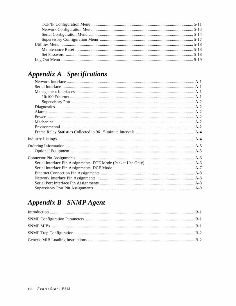
TCP/IP Configuration Menu ............................................................................................... 5-11Network Configuration Menu ............................................................................................. 5-13Serial Configuration Menu .................................................................................................. 5-14Supervisory Configuration Menu ........................................................................................ 5-17
Utilities Menu ............................................................................................................................. 5-18Maintenance Reset ............................................................................................................... 5-18Set Password ........................................................................................................................ 5-18
Log Out Menu ............................................................................................................................ 5-19
Appendix A SpecificationsNetwork Interface ........................................................................................................................ A-1Serial Interface ............................................................................................................................ A-1Management Interfaces ............................................................................................................... A-1
10/100 Ethernet ..................................................................................................................... A-1Supervisory Port ................................................................................................................... A-2
Diagnostics .................................................................................................................................. A-2Alarms ......................................................................................................................................... A-2Power ........................................................................................................................................... A-2Mechanical .................................................................................................................................. A-2Environmental ............................................................................................................................. A-2Frame Relay Statistics Collected in 96 15-minute Intervals ....................................................... A-4
Industry Listings ................................................................................................................................ A-4
Ordering Information ......................................................................................................................... A-5Optional Equipment .................................................................................................................... A-5
Connector Pin Assignments ............................................................................................................... A-6Serial Interface Pin Assignments, DTE Mode (Packet Use Only) ............................................. A-6Serial Interface Pin Assignments, DCE Mode ........................................................................... A-7Ethernet Connection Pin Assignments ........................................................................................ A-8Network Interface Pin Assignments ............................................................................................ A-8Serial Port Interface Pin Assignments ......................................................................................... A-8Supervisory Port Pin Assignments .............................................................................................. A-9
Appendix B SNMP AgentIntroduction .........................................................................................................................................B-1
SNMP Configuration Parameters .......................................................................................................B-1
SNMP MIBs .......................................................................................................................................B-1
SNMP Trap Configuration .................................................................................................................B-2
Generic MIB Loading Instructions .....................................................................................................B-2
viii F r a m e S t a r t F S M
CHAPTER 0PREFACE
About this ManualThis reference guide for the Verilink FrameStart FSM integrated access device (I2AD) describes unit features and specifications, configuration, and cabling. It is not a users guide containing step-by-step procedures. This manual is designed to be used as a reference regarding commands, interface ports, configuration parameters, and other information specific to your FSM unit.
Manual Organization
The chapters and appendices in this manual are arranged for quick reference when you need it. You do not have to read previous chapters to understand the subsequent chapters. Appendices are designed to complement the main chapters.
• Chapter 1, “About the FrameStart FSM” – This chapter describes product features and capabilities.
• Chapter 2, “Installation”– This chapter describes unit port connections and powering information.
• Chapter 3, “Web Server Interface” – This chapter describes the menu screens and configuration parameters accessed through the Web Server interface.
• Chapter 4, “VT100 Interface” − This chapter describes the menu screens and configuration parameters accessed through the VT100 interface.
• Chapter 5, “Front Panel LCD Interface” − This chapter describes how to configure your unit using the front panel.
• Appendix A, “Specifications”– This appendix defines the specifications for the FrameStart FSM. In addition, this section provides ordering information and all the connector pin assignments for the interfaces on the back of the FSM unit.
• Appendix B, “SNMP Agent”− This appendix defines which MIBs (Management Information Base files) are supported by the FrameStart FSM SNMP agent. In addition, instructions are provided for loading these MIB files into most SNMP management stations.
P r e f a c e ix
Typographic Conventions
The following table lists the conventions that are used throughout this guide.
Customer Service and Technical SupportVerilink provides easy access to customer support information through a variety of services. This section describes these services.
Support from Your Network Supplier
If assistance is required, contact your network supplier. Many suppliers are authorized Verilink service partners who are qualified to provide a variety of services, including network planning, installation, hardware maintenance, application training, and support services. When you contact your network supplier for assistance, have the following information ready:
• Diagnostic error messages
• A list of system hardware and software, including revision levels
• Details about recent configuration changes, if applicable
Support from Verilink
If you are unable to receive support from your network supplier or want to contact us directly, Verilink offers worldwide customer support by telephone, e-mail, and through Verilink’s Internet Web site.
Telephone
Customer support is available by telephone 24 hours a day, 7 days a week. To speak directly with a Verilink customer service representative, you may dial one of the following numbers:
•Sales and Marketing: 800-VERILINK (837-4546)
•Technical Support: 800-285-2755 (toll-free)256-327-2255 (local)
Convention Description
A Notice calls attentions to important features or instructions.
A Caution alerts you to serious risk of data loss or other results that may cause you or the unit trouble if the warning is not heeded.
A Warning alerts you to the risk of serious damage to the unit or injury and possible death to the end user.
x F r a m e S t a r t F S M
You can request sales and marketing information or pose a technical support question about your Verilink product by contacting us at the e-mail addresses provided below. Verilink will respond to e-mailed requests for support during regular business hours (8–5 CST, Monday–Friday).
•Sales and Marketing: [email protected]
•Technical Support: [email protected]
Internet
Visit Verilink’s Web site to access the latest Verilink product information, technical publications, news releases, contact information, and more:
http://www.verilink.com
If this reference manual is revised to reflect code changes or other updates, the most recent version will be posted to the Verilink Web site.
Returning a Unit to VerilinkIf for any reason you must return your Verilink product, it must be returned with the shipping prepaid, and packaged to the best commercial standard for electronic equipment. Verilink will pay shipping charges for delivery on return. You are responsible for mode and cost of shipment to Verilink.
You must have a Return Material Authorization (RMA) number marked on the shipping package. To obtain an RMA number, call Customer Service at 800-926-0085, extension 2282 or 2232. Products sent to Verilink without RMA numbers will be returned to the sender unopened, at the sender’s expense.
When calling Verilink for an RMA number, please have the following information available:
• Model number and serial number for each unit
• Reason for return and symptoms of problem
• Purchase order number to cover charges for out-of-warranty items
• Name and phone number of person we can contact if we have questions about the unit(s)
The address for you to use when returning a unit to Verilink will be provided when the RMA is issued. The standard delivery method for return shipments is Standard Ground for domestic returns and International Economy for international returns (unless otherwise specified).
P r e f a c e xi

xii F r a m e S t a r t F S M
C H A P T E R
1CHAPTER 1ABOUT THE FRAMESTART FSMFrame relay's low-cost, high connectivity, and efficient throughput advantages can be realized only when networks are installed and performing properly. Verilink's FrameStart™ FSM® is a full-featured, SNMP-managed T1 DSU/CSU that targets customer premise applications using public frame relay or private line services over a T1 facility. The FrameStart FSM operates at fractional T1 rates up to full T1 carrier service. In addition, the FSM operates as a traditional DSU/CSU over T1/FT1 facilities.
About FrameStart TechnologyThe FSM’s FrameStart technology ensures that frame relay service is operational prior to installation and connection to other equipment. FrameStart’s integral frame relay circuit installation and diagnostic tools help reduce equipment and installation costs, simplify configuration setup, and alleviate frame relay connection uncertainties − all in one unit.
Verilink’s FSM supports both FrameStart Install mode and FrameStart Monitor mode as well as Layer 2 statistics gathering and diagnostic capabilities that maximize network availability and manage the growth of the network.
FrameStart Install enables step-by-step validation of network operations and requires no data terminal equipment such as routers or FRADs. If a DTE device is connected, operation is halted to perform installation diagnostics. With FrameStart Install, you have the power to perform advanced tests that include the following:
• Local Management Interface (LMI) Sourcing
• End-to-end Integrity
• PVC Delay Testing
• Network Receive Level
FrameStart Monitor complements FrameStart Install to monitor real-time network conditions nonintrusively when connected to real-world applications. FrameStart Monitor diagnostics maintain and manage the activity of the frame
A b o u t t h e F r a m e S t a r t F S M 1-1
relay network from the host FrameStart unit. FrameStart Monitor also performs the following:
• LMI Monitoring
• LMI Auto-Sourcing
• SOS Mode
• New Circuit Installation
FSM Overview and AdvantagesManaged FrameStart is an innovative, highly intelligent, software-based WAN access device optimized for frame relay access. The FSM provides network managers with all the tools necessary to monitor and troubleshoot frame relay transport systems. In addition, FSM products deliver valuable tools for the following:
• Measuring and reporting performance
• Verifying Service Level Agreements (SLAs)
• Managing network resources to ensure optimum performance
• Analyzing trends to aid in network planning
• Managing Web browser and/or in-band/out-of-band SNMP
FSM advantages include the following:
• Controls recurring frame relay access costs − FSM products quickly pay for themselves by allowing enterprises and service providers to optimize the use of valuable bandwidth
• Ensures a higher level of service − FSM acts as an expert frame relay Service Level Advisor for service providers and users.
• Introduces new value-added offerings − FSM is a stepping stone to a new series of access services.
• Lowers facility costs − FSM's easy installation and configuration cut down on maintenance and sparing costs.
The FSM can be deployed with the Verilink’s FST and FSD products to offer the lowest cost circuit management solution in the market. FrameStart reduces the time required to install and configure PVCs, and monitors the reliability of virtual circuits in a frame-relay network. The FSM can also be deployed with FSMs at all sites to provide SLA monitoring and real-time delay measurements across a frame relay network.
Features SummaryThe FrameStart FSM is a single, standards-based frame relay monitoring solution that provides the following features:
1-2 F r a m e S t a r t F S M
• A Powerful Core Architecture:
• 10/100Base-T Ethernet port for Management
• Software-configurable Serial port for RS 232, EIA 530, or V.35
• PowerPC™ platform with 16 MBytes RAM
• Asynchronous Supervisory port for local management via VT100
• A Suite of Performance Monitoring Tools:
• Monitoring capability for up to 128 virtual circuits (Data Link Connection Identifiers, or DLCIs)
• T1 performance monitoring, including complete diagnostic capabilities and test modes
• Service Level Agreement (SLA) monitoring and management
• Committed Information Rate (CIR) enforcement per DLCI
• Programmable alarm thresholds
• Management Interfaces:
• WANsight − an innovative, embedded Web-based user interface for remote configuration and real-time reporting via Web browser (Verilink recommends Microsoft Internet Explorer 5.0 or higher) that decreases installation and configuration time for service employees, simplifies troubleshooting and fault isolation of network problems, and optimizes management of both TDM and frame-based services
• VT100 or TELNET
• Local Supervisory port
• Ethernet port for Management
• Liquid crystal display (LCD)
• Frame Relay Aware:
• Supports leased-line and frame relay services
• Layer 2 end-to-end visibility and control
Front Panel The front panel of the FrameStart FSM provides three user-activated input control buttons, four LED status indicators, and a 2-line, 16-character LCD that provides access to unit configuration, diagnostics, and utilities.
A b o u t t h e F r a m e S t a r t F S M 1-3
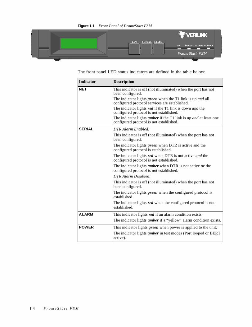
Figure 1.1 Front Panel of FrameStart FSM
The front panel LED status indicators are defined in the table below:
Indicator Description
NET This indicator is off (not illuminated) when the port has not been configured. The indicator lights green when the T1 link is up and all configured protocol services are established.The indicator lights red if the T1 link is down and the configured protocol is not established. The indicator lights amber if the T1 link is up and at least one configured protocol is not established.
SERIAL DTR Alarm Enabled:
This indicator is off (not illuminated) when the port has not been configured.
The indicator lights green when DTR is active and the configured protocol is established.
The indicator lights red when DTR is not active and the configured protocol is not established.
The indicator lights amber when DTR is not active or the configured protocol is not established.
DTR Alarm Disabled:
This indicator is off (not illuminated) when the port has not been configured.
The indicator lights green when the configured protocol is established.
The indicator lights red when the configured protocol is not established.
ALARM This indicator lights red if an alarm condition exists
The indicator lights amber if a “yellow” alarm condition exists.
POWER This indicator lights green when power is applied to the unit.
The indicator lights amber in test modes (Port looped or BERT active).
1-4 F r a m e S t a r t F S M
The user-activated input control buttons used to access and set configuration and control options from the LCD menus are defined in the table below:
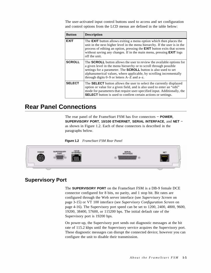
Rear Panel ConnectionsThe rear panel of the FrameStart FSM has five connectors − POWER, SUPERVISORY PORT, 10/100 ETHERNET, SERIAL INTERFACE, and NET − as shown in Figure 1.2. Each of these connectors is described in the paragraphs below.
Supervisory Port
The SUPERVISORY PORT on the FrameStart FSM is a DB-9 female DCE connector configured for 8 bits, no parity, and 1 stop bit. Bit rates are configured through the Web server interface (see Supervisory Screen on page 3-15) or VT 100 interface (see Supervisory Configuration Screen on page 4-16). The Supervisory port speed can be set to 1200, 2400, 4800, 9600, 19200, 38400, 57600, or 115200 bps. The initial default rate of the Supervisory port is 19200 bps.
On power-up, the Supervisory port sends out diagnostic messages at the bit rate of 115.2 kbps until the Supervisory service acquires the Supervisory port. These diagnostic messages can disrupt the connected device; however you can configure the unit to disable their transmission.
Button Description
EXIT The EXIT button allows exiting a menu option which then places the unit in the next higher level in the menu hierarchy. If the user is in the process of editing an option, pressing the EXIT button exits that screen without saving any changes. If in the main menu, pressing EXIT logs off the unit.
SCROLL The SCROLL button allows the user to review the available options for a given level in the menu hierarchy or to scroll through possible settings for a parameter. The SCROLL button is also used to set alphanumerical values, where applicable, by scrolling incrementally through digits 0–9 or letters A–Z and a–z.
SELECT The SELECT button allows the user to select the currently displayed option or value for a given field, and is also used to enter an “edit” mode for parameters that require user-specified input. Additionally, the SELECT button is used to confirm certain actions or settings.
Figure 1.2 FrameStart FSM Rear Panel
A b o u t t h e F r a m e S t a r t F S M 1-5
NOTICE: For information on pinout assignments for this connector, refer to Supervisory Port Pin Assignments on page A-9. See Ordering Information on page A-5 for information on cables for this connector.
10/100 Ethernet
The FrameStart FSM provides one 10/100 ETHERNET interface. This interface is an eight-pin modular jack that complies with standard twisted-pair, 10/100Base-T requirements. The 10/100Base-T cable is supplied by the end user. Refer to Ethernet Connection Pin Assignments on page A-8 for pin assignments and cable descriptions.
Ethernet LED Indicators
There are two unlabeled indicator LEDs on either side of the 10/100 ETHERNET jack. The LED on the left side of the jack pulses amber to indicate data activity (either transmit or receive). The LED on the right side of the jack lights green to indicate that the link layer is operational.
Serial Interface
The SERIAL INTERFACE located on the rear of the unit is a multi-protocol interface presented physically as a DB-25 connection. The protocols supported by this interface are RS-232, EIA-530, and V.35. Cables that adapt the DB-25 interface to the 34-pin V.35 interface are available. These cables are optional equipment and their part numbers are listed in Optional Equipment on page A-5. There are also DB-25 to DB-25 cables available if your installation needs require them. See Ordering Information on page A-5 for details. Pin assignments for the Serial interface are listed in Serial Port Interface Pin Assignments on page A-8.
CAUTION: FCC rules require that interconnecting cables carrying high-speed data be shielded appropriately to minimize radio frequency interference.
Network Interface
Labeled on the rear panel of the FrameStart FSM as NET, this interface connection is a standard RJ-48C, 8-pin modular jack that contains an automatic line build out (ALBO) allowing the unit to be located a substantial distance away from the telco network interface with a receive signal level to −27 dB. To view the pinout assignments for this connection, refer to Network Interface Pin Assignments on page A-8.
The Network interface transmit LBO level should be set as instructed under Line Build-Out (Long Haul) on page 3-5. Maximum suggested cable lengths for the connection from the unit to the network are listed in the table below.
1-6 F r a m e S t a r t F S M
Calculations are based on a cable temperature of 70 °F, 0.083 µF/mile capacitance, a 27-dB loss, and a 100-Ω, non-loaded, twisted-pair cable.
CAUTION: In accordance with FCC Rules, Part 68.218(b), you must notify the telephone company prior to disconnecting this product.
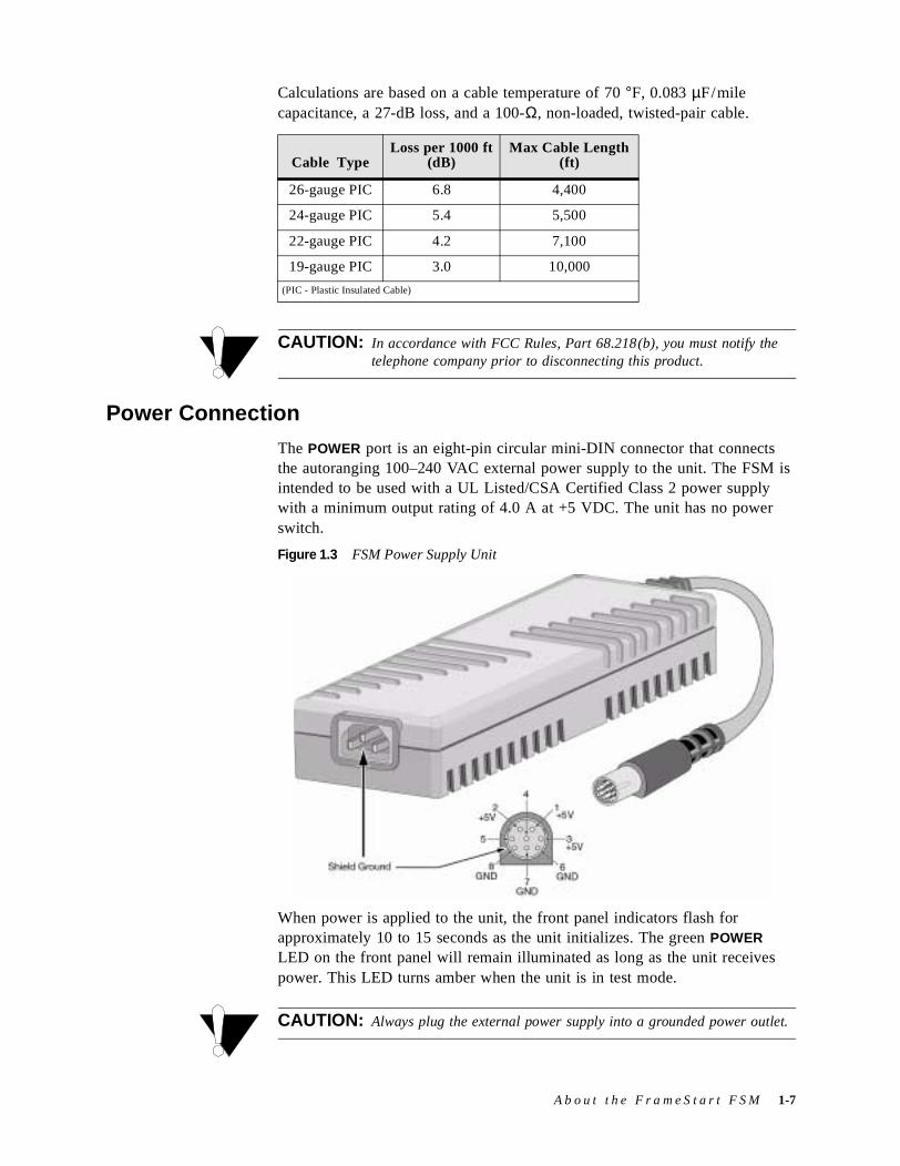
Power Connection
The POWER port is an eight-pin circular mini-DIN connector that connects the autoranging 100–240 VAC external power supply to the unit. The FSM is intended to be used with a UL Listed/CSA Certified Class 2 power supply with a minimum output rating of 4.0 A at +5 VDC. The unit has no power switch.
Figure 1.3 FSM Power Supply Unit
When power is applied to the unit, the front panel indicators flash for approximately 10 to 15 seconds as the unit initializes. The green POWER LED on the front panel will remain illuminated as long as the unit receives power. This LED turns amber when the unit is in test mode.
CAUTION: Always plug the external power supply into a grounded power outlet.
Cable TypeLoss per 1000 ft
(dB)Max Cable Length
(ft)
26-gauge PIC 6.8 4,400
24-gauge PIC 5.4 5,500
22-gauge PIC 4.2 7,100
19-gauge PIC 3.0 10,000
(PIC - Plastic Insulated Cable)
A b o u t t h e F r a m e S t a r t F S M 1-7
NOTICE: Per UL 1950 and CSA 950 Clause 1.7.2, if the power supply cord is intended to serve as a disconnect device, an easily accessible socket must be installed near the equipment.
Power Failure
If the indicator does not illuminate, check the power connections and the primary AC circuit breaker.
The FrameStart FSM provides non-volatile memory retention of the unit configuration in case of a power failure. This feature allows the unit to automatically restore normal service following a power loss and retain pre-existing time and date information.
NOTICE: Configuration parameters have not been stored into non-volatile memory until the Mode LED is green.
1-8 F r a m e S t a r t F S M

C H A P T E R
2CHAPTER 2INSTALLATION
This chapter describes the contents of your FSM shipment and provides information on connecting and installing the unit.
The FSM uses an “Installation Wizard” to help you automatically install the unit quickly and accurately. Procedures for using this Installation Wizard are also described in this chapter.
Unpacking and InspectionThe FrameStart FSM is shipped in cardboard cartons with foam inserts for shock and vibration protection. When your shipment arrives, inspect the shipping container and contents, and compare all items with those listed on the packing list.
If the contents of the shipment are incomplete or if there is mechanical damage or defect, notify Verilink Customer Service (see page x). If the shipping container or cushioning material is damaged, notify the carrier and Verilink immediately and make a notation on the delivery receipt that the container was damaged. (If possible, obtain the signature and name of the person making delivery.) Retain the packaging material until the contents of the shipment have been checked for completeness and the unit has been checked both mechanically and electrically.
Supplied MaterialsThe FrameStart FSM unit ships with the following standard items:
• External power supply
• T1 network cable
• Serial (Supervisory) cable
• Verilink Documentation CD
I n s t a l l a t i o n 2-1
For specific applications, see Optional Equipment on page A-5 for additional cables and adapters. Contact Technical Support (see page x) for further assistance.
Installation WizardThe FSM can be configured and monitored through the Web Server interface, the VT100 interface, or the Front Panel interface, but the unit must first be configured with an IP address. You can configure the unit’s IP address using either the LCD on the front panel (refer to the TCP/IP Configuration Menu on page 5-11) or the Verilink Configuration Wizard, which is included on your documentation CD.
NOTICE: You may also access the Verilink Configuration Wizard on Verilink’s Web site: www.verilink.com.
To configure the IP Address using the Verilink Configuration Wizard, perform the steps listed below:
1 Using the supplied cable, connect the unit’s DB-9 Supervisory port to a COM port on your PC. (Take note of which COM port is connected.)
2 Insert the Verilink CD-ROM disc (provided with the FSM) into your PC’s CD-ROM drive.
3 Use Windows “Explore” to view the contents of the CD and select the folder labeled “Utilities.” In this folder will be a file named ipwiz.exe; this executable file is the Verilink Configuration Wizard application. Double-click on this file to launch the program. After the program is fully launched, you will see the following screen:
4 Using the Tab key to move from field to field, move the cursor to the “COM Port” field. Using the Spacebar, toggle between the available options until the correct COM port is shown (COM1, COM2, COM3 or COM4). Be sure to choose the same COM port as the port to which the unit is connected.
2-2 F r a m e S t a r t F S M
5 By default, the “Baud Rate” field will display 115200 (bits per second). For the purpose of this installation, do not change the displayed baud rate from its default. Proceed directly to the next step.
6 Using the Tab key again, move the cursor to the “IP Address” field and enter the appropriate IP Address for the unit (xxx.xxx.xxx.xxx). If necessary, repeat this process for the “Subnet Mask” and “Gateway Address” fields.
7 Next, move the cursor to the “Write To Unit” field and press the Enter key. The program will prompt you to reset the unit.
8 To reset the unit, press the Reset button on the front of the FSM. The Configuration Wizard will then automatically download the configuration information to the unit.
9 Note the status messages displayed at the bottom of the Configuration Wizard screen. When the download is complete, your PC will beep and the status message bar will display “Finished.”
10 Finally, move the cursor to the Exit prompt and press Enter. The Configuration Wizard program will close.
I n s t a l l a t i o n 2-3

2-4 F r a m e S t a r t F S M
C H A P T E R
3CHAPTER 3WEB SERVER INTERFACE
The FSM has an innovative, embedded Web-based user interface (WANsight) for remote configuration and real-time reporting via Microsoft Internet Explorer 5.0 or higher. Access to the Web server interface and how the interface is used to configure the FSM0 unit are described in detail below.
NOTICE: Verilink recommends the use of Microsoft’s Internet Explorer 5.0 or higher because if you use other Internet browsers to access the Web server interface, screen elements will not display as described in this manual.
NOTICE: The material presented in this chapter follows the order listed in the navigation bar on the left side of the Web Server interface screen. However, because the parameters you specify in the Service Table attach protocols to interfaces, you must configure the Service Table first. (See Services Screen on page 3-16.) You will not be able to allocate channels (see Channel Table Details Screen on page 3-18) until the Service Table has been configured.
Configuration through the VT100 interface is covered in Chapter 4, and configuration through the Front Panel interface is covered in Chapter 5.
Web Server Interface AccessYou can access the Web server interface by connecting to its IP address. This connection can be directly through the 10/100 Ethernet port, in-band via PPP over any port, or in-band via encapsulated IP traffic on the Frame Relay circuit.
NOTICE: Any changes to the unit’s configuration MUST be followed by a “Submit” if there is a “Submit” key on the menu. If you change the Service Table, you must perform a “Save and Restart.”
W e b S e r v e r I n t e r f a c e 3-1
To access the Web Server interface, type the unit’s IP address in the browser’s Address (or Location) field and press the “Enter” key.
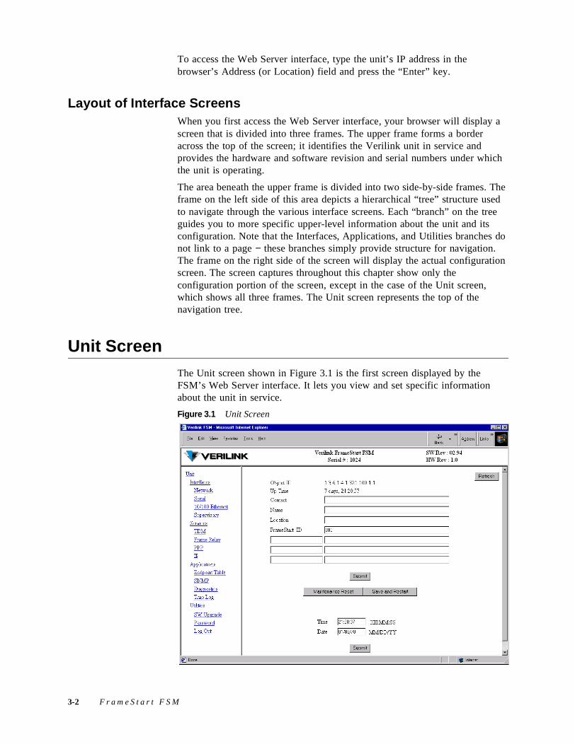
Layout of Interface Screens When you first access the Web Server interface, your browser will display a screen that is divided into three frames. The upper frame forms a border across the top of the screen; it identifies the Verilink unit in service and provides the hardware and software revision and serial numbers under which the unit is operating.
The area beneath the upper frame is divided into two side-by-side frames. The frame on the left side of this area depicts a hierarchical “tree” structure used to navigate through the various interface screens. Each “branch” on the tree guides you to more specific upper-level information about the unit and its configuration. Note that the Interfaces, Applications, and Utilities branches do not link to a page − these branches simply provide structure for navigation. The frame on the right side of the screen will display the actual configuration screen. The screen captures throughout this chapter show only the configuration portion of the screen, except in the case of the Unit screen, which shows all three frames. The Unit screen represents the top of the navigation tree.
Unit ScreenThe Unit screen shown in Figure 3.1 is the first screen displayed by the FSM’s Web Server interface. It lets you view and set specific information about the unit in service.
Figure 3.1 Unit Screen
3-2 F r a m e S t a r t F S M
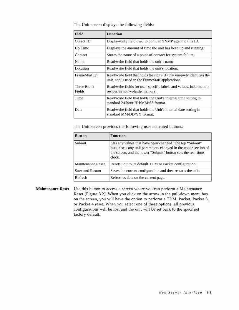
The Unit screen displays the following fields:
The Unit screen provides the following user-activated buttons:
Maintenance Reset Use this button to access a screen where you can perform a Maintenance Reset (Figure 3.2). When you click on the arrow in the pull-down menu box on the screen, you will have the option to perform a TDM, Packet, Packet 3, or Packet 4 reset. When you select one of these options, all previous configurations will be lost and the unit will be set back to the specified factory default.
Field Function
Object ID Display-only field used to point an SNMP agent to this ID.
Up Time Displays the amount of time the unit has been up and running.
Contact Stores the name of a point-of-contact for system failure.
Name Read/write field that holds the unit’s name.
Location Read/write field that holds the unit's location.
FrameStart ID Read/write field that holds the unit's ID that uniquely identifies the unit, and is used in the FrameStart applications.
Three Blank Fields
Read/write fields for user-specific labels and values. Information resides in non-volatile memory.
Time Read/write field that holds the Unit's internal time setting in standard 24-hour HH:MM:SS format.
Date Read/write field that holds the Unit's internal date setting in standard MM/DD/YY format.
Button Function
Submit Sets any values that have been changed. The top “Submit” button sets any unit parameters changed in the upper section of the screen, and the lower “Submit” button sets the real-time clock.
Maintenance Reset Resets unit to its default TDM or Packet configuration.
Save and Restart Saves the current configuration and then restarts the unit.
Refresh Refreshes data on the current page.
W e b S e r v e r I n t e r f a c e 3-3
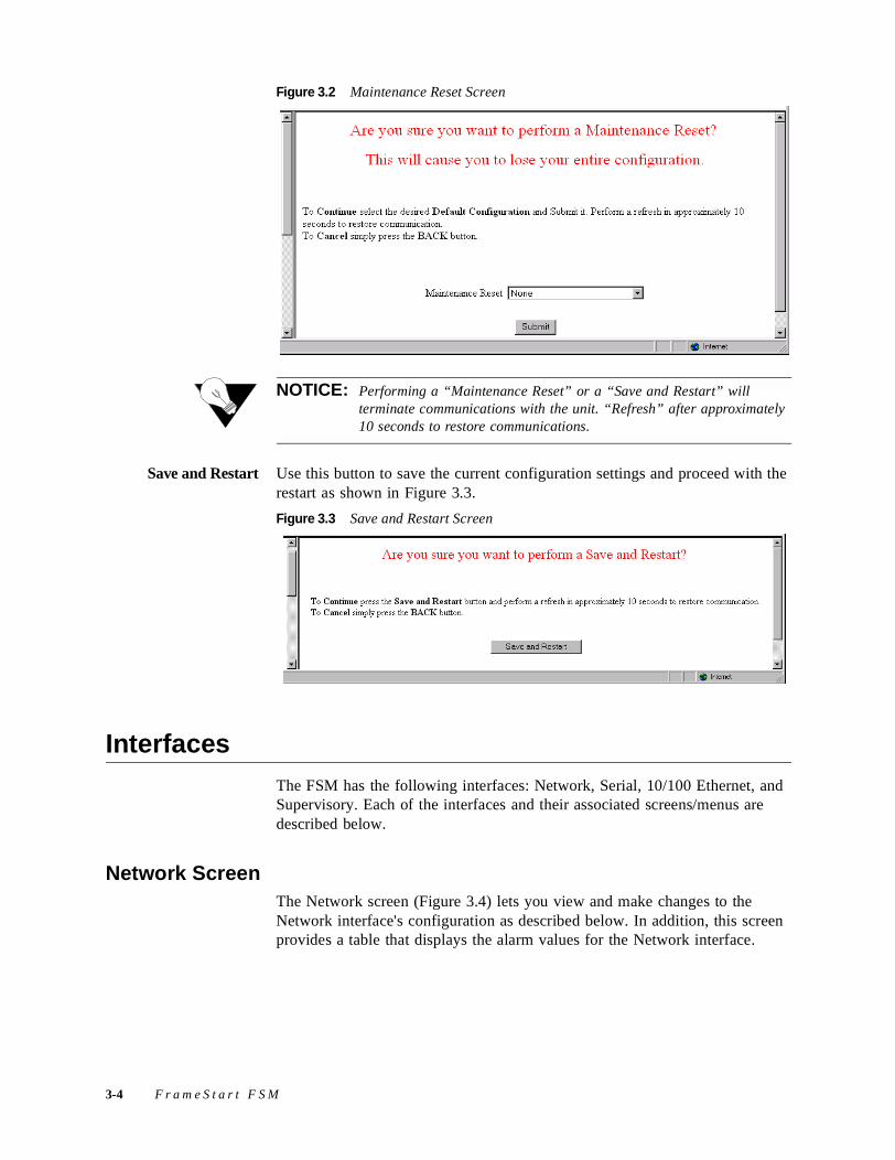
Figure 3.2 Maintenance Reset Screen
NOTICE: Performing a “Maintenance Reset” or a “Save and Restart” will terminate communications with the unit. “Refresh” after approximately 10 seconds to restore communications.
Save and Restart Use this button to save the current configuration settings and proceed with the restart as shown in Figure 3.3.
Figure 3.3 Save and Restart Screen
InterfacesThe FSM has the following interfaces: Network, Serial, 10/100 Ethernet, and Supervisory. Each of the interfaces and their associated screens/menus are described below.
Network ScreenThe Network screen (Figure 3.4) lets you view and make changes to the Network interface's configuration as described below. In addition, this screen provides a table that displays the alarm values for the Network interface.
3-4 F r a m e S t a r t F S M
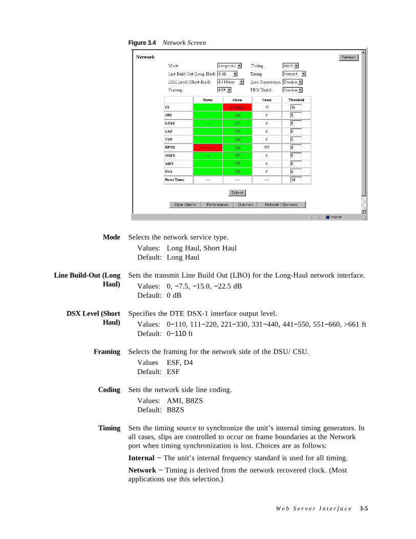
Figure 3.4 Network Screen
Mode Selects the network service type.
Values: Long Haul, Short HaulDefault: Long Haul
Line Build-Out (LongHaul)
Sets the transmit Line Build Out (LBO) for the Long-Haul network interface.
Values: 0, −7.5, −15.0, −22.5 dBDefault: 0 dB
DSX Level (ShortHaul)
Specifies the DTE DSX-1 interface output level.
Values: 0−110, 111−220, 221−330, 331−440, 441−550, 551−660, >661 ftDefault: 0−110 ft
Framing Selects the framing for the network side of the DSU/ CSU.
Values ESF, D4Default: ESF
Coding Sets the network side line coding.
Values: AMI, B8ZSDefault: B8ZS
Timing Sets the timing source to synchronize the unit’s internal timing generators. In all cases, slips are controlled to occur on frame boundaries at the Network port when timing synchronization is lost. Choices are as follows:
Internal − The unit’s internal frequency standard is used for all timing.
Network − Timing is derived from the network recovered clock. (Most applications use this selection.)
W e b S e r v e r I n t e r f a c e 3-5
Serial – Timing is derived from the Serial port recovered clock.
Zero Suppression Determines whether ones density insertion is activated after 15 zeros. This parameter is ignored if the Coding parameter is set to “B8ZS.”
Values: Disable, EnableDefault: Disable
PRM Enable Lets you establish which performance messaging standard will be employed to initiate Performance Report Message (PRM) functions. Setting this field to “Enable” instructs the unit to use ANSI T1.403, which sends a PRM once every second. Setting this field to “Disable” instructs the unit to use AT&T TR54016, which provides performance reporting on request only.
Values: Disable, EnableDefault: Disable
Error Status and Alarm Thresholds Table
The unit can be programmed to generate an alarm condition based on a specific level of performance degradation. The Network screen presents a table that provides current error status and alarm threshold information.
Acceptable alarm thresholds are set for periods of 15 minutes (900 seconds) and are sampled every second. The error types listed in the following paragraphs can be preset to a value between 0 and 900 seconds. Setting a field to “0” (zero) disables the alarm on that statistic. To effectively disable alarm reporting, set all fields to “0” (zero).
The 15-minute time frame is a time window based on the accumulated counts over the previous fifteen 1-minute intervals. In all cases, if the number of actual network errored seconds in the previous 15 minutes reaches the preset threshold for the specified error type, an alarm condition is declared.
The four sections of the status table are:
The Network Error Status table provides information on the following error parameters:
ES Sets the Errored Seconds (ES) threshold. An ES is a 1-second period in which at least one logic error occurred. The default value is 45 seconds.
SES Sets the Severely Errored Seconds (SES) threshold. An SES is a 1-second period in which at least 320 CRC errors or one Out-of-Frame (OOF) error occurred. The default value is 5 seconds.
• Status Displays the current status of the network port.
• Alarm Displays the alarm value of the network port. The unit declares an alarm as soon as the count exceeds the threshold set.
• Count Displays the number of events or occurrences of this statistic that have been detected.
• Threshold Read/write field that can be set to a desirable threshold.
3-6 F r a m e S t a r t F S M
LOSS Sets the Loss of Signal Seconds (LOSS) threshold. A LOSS is a 1-second period in which the T1 received signal is interrupted. The default value is 5 seconds.
UAS Sets the Unavailable Seconds (UAS) threshold. A UAS is a 1-second period in which consecutive severely errored seconds cause an unavailable state. The default is 0 (zero) seconds (Disabled).
CSS Sets the Controlled Slip Seconds (CSS) threshold. The default is 0 (zero) seconds (Disabled).
BPVS Sets the Bipolar Violation Errored Seconds (BPVS) threshold. A BPVS is a 1-second period in which at least one bipolar violation occurred. The default is 0 (zero) seconds (Disabled).
OOFS Sets the Out of Frame Seconds (OOFS) threshold. An OOFS is a 1-second period in which a frame sync loss occurred. The default value is 5 (five) seconds.
AISS Sets the Alarm Indication Signal Seconds (AISS) threshold. An AIS is a 1-second period when unframed all ones are received. The default is 0 (zero) seconds (Disabled).
RAS Sets the Remote Alarm Seconds (RAS) threshold. A RAS is generated by the terminal equipment when an improper signal is received from the facility (or upon receipt of unframed all ones). The default is 0 (zero) seconds (Disabled).
Reset Timer Sets the Reset Timer threshold. This field is the contiguous number of seconds that an alarm parameter must be clear before the alarm is reset. Applicable values range from 000 through 900. A value of “000” means that the alarm will never be reset.
The Network screen provides the following user-activated buttons:
CAUTION: Performance data will be lost upon power cycle or after performing a Maintenance Reset or a Save and Restart.
Button Function
Submit Sets any values that have been changed.
Clear Alarms Resets the alarm conditions and counts to zero.
Performance Displays a Performance/Summary screen (Figure 3.5) that shows a current count of the number of error events that have occurred over the past 24 hours and the past 30 days.
Channels Displays the Channel Table Details Screen on page 3-19, showing each channel by index number. Each channel’s rate and service (by number) are displayed and can be changed through user input.
Network Services Displays the Services screen for the Network interface.
Refresh Refreshes data on the current page.
W e b S e r v e r I n t e r f a c e 3-7
Figure 3.5 Performance/Summary Screen
In addition to the error parameters found in the Error Status and Alarm Thresholds Table on page 3-6, the following error parameters are included on the Network Performance/Summary table:
BES Sets the Bursty Error Seconds (BES) threshold. A BES is a 1-second period during which at least more than one but fewer than 320 CRC6 errors occurred.
LOFC The Loss of Frame Count (LOFC) represents the number of time a loss of frame is declared. A loss of frame is declared after 2.5 seconds of continuous loss of signal or OOF.
CRCES Sets the Cyclic Redundancy Check Errored Seconds (CRCES) threshold. A CRC is a method of confirming the integrity of received data.
Beneath the Performance/Summary table are two buttons: “Performance 24 Hour” and “Performance 30 Day.” Clicking on either of these will display a detailed summary of error events that have occurred during each 15-minute interval of the past 24 hours (Figure 3.6) or during each 24-hour interval of the past 30 days (Figure 3.7). The error parameters are the same as those found on the Performance/Summary table. Representations of these screens are provided below.
3-8 F r a m e S t a r t F S M
Figure 3.6 Network Performance 24 Hour Screen
Figure 3.7 Network Performance 30 Day Screen
Serial ScreenThe Serial screen (Figure 3.8) lets you view and make changes to the Serial interface's configuration as described below.
W e b S e r v e r I n t e r f a c e 3-9
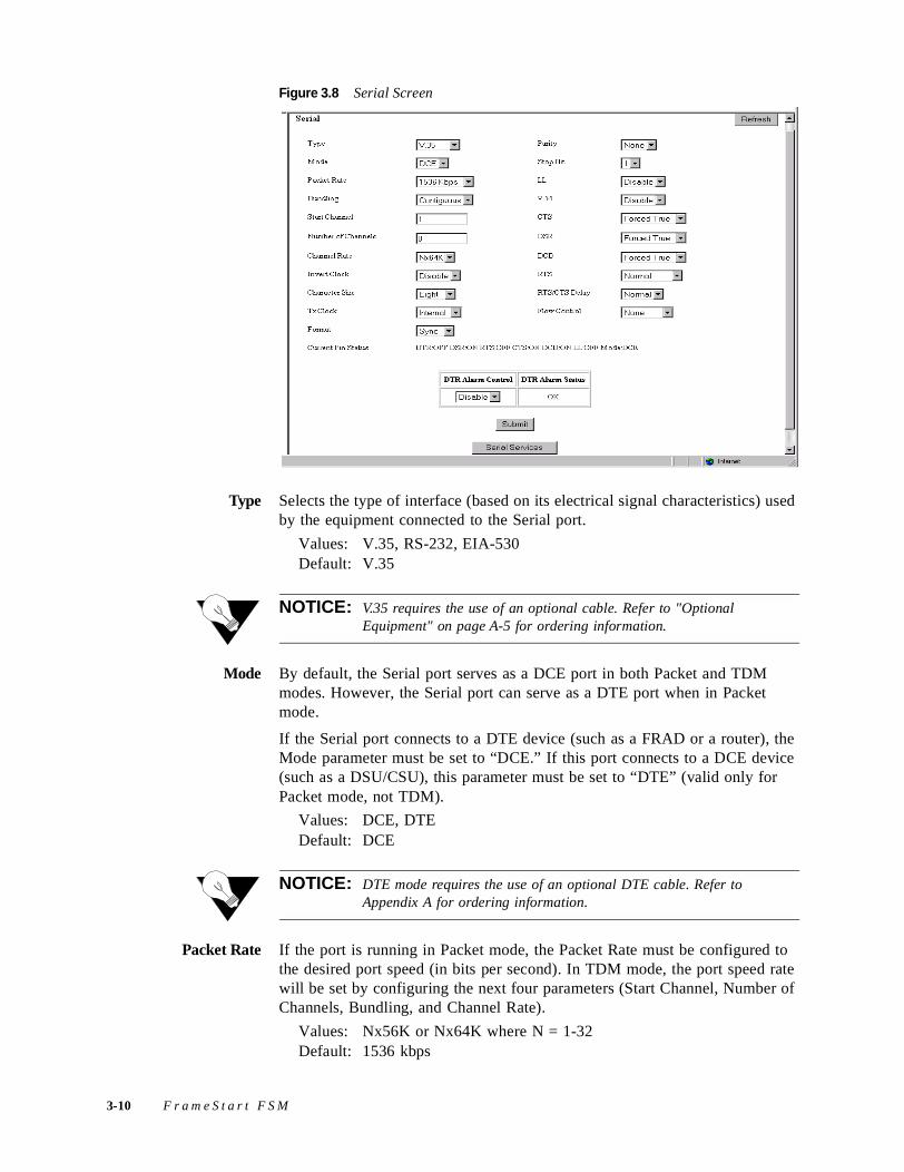
Figure 3.8 Serial Screen
Type Selects the type of interface (based on its electrical signal characteristics) used by the equipment connected to the Serial port.
Values: V.35, RS-232, EIA-530Default: V.35
NOTICE: V.35 requires the use of an optional cable. Refer to "Optional Equipment" on page A-5 for ordering information.
Mode By default, the Serial port serves as a DCE port in both Packet and TDM modes. However, the Serial port can serve as a DTE port when in Packet mode.
If the Serial port connects to a DTE device (such as a FRAD or a router), the Mode parameter must be set to “DCE.” If this port connects to a DCE device (such as a DSU/CSU), this parameter must be set to “DTE” (valid only for Packet mode, not TDM).
Values: DCE, DTEDefault: DCE
NOTICE: DTE mode requires the use of an optional DTE cable. Refer to Appendix A for ordering information.
Packet Rate If the port is running in Packet mode, the Packet Rate must be configured to the desired port speed (in bits per second). In TDM mode, the port speed rate will be set by configuring the next four parameters (Start Channel, Number of Channels, Bundling, and Channel Rate).
Values: Nx56K or Nx64K where N = 1-32Default: 1536 kbps
3-10 F r a m e S t a r t F S M
Bundling Selects whether the DTE channel assignment is made as a “Contiguous” group or as “Alternate” channels. Selecting “Alternate” ensures ones density. Because the unit allows individual channels to be configured for a service, a value of “Arbitrary” will be returned for this parameter if the current channel allocation is not contiguous or Alternate. The “Arbitrary” value can only be supplied by the unit − it cannot be set by the user.
Values: Contiguous, Alternate, ArbitraryDefault: Contiguous
NOTICE: Because “Alternate” Bundling assigns every other channel, only half the channels are available.
Start Channel Selects the starting channel in the 24-channel DS1 bit stream. Starting with the specified channel, the unit automatically assigns the channels that follow.
Values: 1 through 24Default: 1
Number of Channels Shows the number of channels to be passed through to the DTE.
Values: 0 through 24Default: 24
Channel Rate The unit can operate at any data rate that is a multiple of 56 or 64 kbps. If “Νx64K” is selected, the ones density requirements of the T1 network line must be ensured. If “Νx56K” is selected, ones density for the selected DS0 channel is maintained.
Values: Nx56K, Nx64KDefault: Nx64K
NOTICE: Start Channel, Number of Channels, and Channel Rate cannot be changed if Bundling is not also changed from “Arbitrary.”
Invert Clock In DTE Packet mode, this parameter changes the clock edge of the transmitted data. The Invert Clock parameter is only available for use in DTE mode.
Values: Disable, EnableDefault: Disable
Character Size Selects the number of bits required to make up one asynchronous character.
Values: Five, Six, Seven, EightDefault: Eight
Tx Clock Selects the clock the unit uses to sample the data transmitted from the DTE. When set to “Internal,” the data is sampled directly with the transmit data clock that is also supplied to the DTE as Transmit Clock. The “External” option uses the external clock from the DTE.
Values: Internal, ExternalDefault: Internal
W e b S e r v e r I n t e r f a c e 3-11
NOTICE: The “External” option is valid only in Packet mode.
Format Selects the port’s operating mode.
Values: Sync, AsyncDefault: Sync
Parity Sets the parity bit if the port is asynchronous.
Values: None, Odd, EvenDefault: None
Stop Bit Selects the number of bits required to end the character.
Values: 1, 2Default: 1
LL The Local Loopback parameter can be set to “Enable” or “Disable.” Selecting “Enable” allows the unit to go into Local Loop when the LL pin on the Serial 1 port goes high. The unit exits the loop when the LL pin goes low. If you select “Disable,” the unit ignores the LL pin on the Serial port.
Values: Disable, EnableDefault: Disable
V.54 Selecting “Enable” allows the unit to respond to in-band V.54 loop codes. If you select “Disable,” the unit ignores these codes.
Values: Disable, EnableDefault: Disable
CTS The Clear To Send parameter can be set to “Forced True,” “Forced False,” or “Internal.” If this parameter is set to “Internal,” the CTS control lead follows the RTS control lead from the DTE after a delay of a duration established by the RTS/CTS Delay parameter.
Values: Forced True, Forced False, InternalDefault: Forced True
DSR Data Set Ready can be set to “Forced True,” “Forced False,” or “Internal.” The “Internal” option sets DSR “On” if the port is enabled and “Off” if the port is disabled.
Values: Forced True, Forced False, InternalDefault: Forced True
DCD The Data Carrier Detect parameter can be set to “Forced True,” “Forced False,” or “Internal.” If set to “Internal,” DCD is “On” when network carrier is being received from the remote end, and is “Off” when network carrier is not being received from the far end.
Values: Forced True, Forced False, InternalDefault: Forced True
RTS The Request To Send parameter determines the source from which the unit reads the RTS signal status. If set to “Normal,” the unit gets RTS from the
3-12 F r a m e S t a r t F S M
DTE on the Serial interface. If set to “Forced True,” RTS is always perceived as “On.”
Values: Normal, Forced TrueDefault: Normal
RTS/CTS Delay The Request To Send/Clear To Send parameter determines how long the unit waits before it changes the level of CTS to match RTS when the CTS parameter is set to “Internal.”
Values: Normal (~30 ms delay), Long (~100 ms delay)Default: Normal
Flow Control Selects the type of flow control to be used if the port is asynchronous.
Values: None, Xon/Xoff, RTS/CTSDefault: None
Current Pin Status
The Current Pin Status, which shows the state of the RS-232 pins, is also displayed on the Serial interface screens.
DTR Alarm Control and Status Table
In addition to the configurable fields, the Serial screen displays a table that lets you set the Data Terminal Ready (DTR) Alarm Control parameters and view the current DTR Alarm Status.
Choices for DTR Alarm Control are “Enable” and “Disable”; the default setting is “Disable.” Setting DTR Alarm Control to “Enable” allows the unit to go into alarm on a loss of DTR, which occurs when the Serial port detects that the DTR signal is low. The DTR Status field indicates the current state of the DTR alarm.
10/100 Ethernet (IP Service Details) ScreenThe 10/100 Ethernet (IP Service Details) screen (Figure 3.9) lets you configure the IP parameters described below.
W e b S e r v e r I n t e r f a c e 3-13
Figure 3.9 10/100 Ethernet Screen (IP Service Details)
Unit IP Address A unique network address assigned to this unit.
Subnet Mask Defines the network portion of the unit’s IP address.
Gateway IP Address IP address of the default gateway (router) on the LAN side of the unit.
DHCP Client If DHCP Client is enabled at power-up, the unit will request its IP, Mask, and Gateway addresses from a DHCP server located on the LAN side of the unit, and the unit will use these addresses. If the DHCP request is unsuccessful, the unit will use the configured addresses shown on this screen.
NOTICE: Always verify that a DHCP server is available on the network before enabling DHCP Client. If, on power-up, a DHCP server is not found, a 60-second timeout will occur.
Client Identifier Displays a unique identifier for a specific IP address.
Physical Address Displays unique MAC address.
NOTICE: If you manually change the IP address, you must “Save and Restart.” (See Save and Restart on page 3-4.) The first three address parameters above can also be configured using the Installation Wizard on page 2-2.
To view details about the current condition of IP, ICMP (In and Out), TCP, and UDP parameters, click the “Ethernet Stats” button at the bottom of the screen. The Ethernet Stats screen (Figure 3.10) contains no user-selectable fields or options; it is simply a representation of the applicable MIB II parameters.
3-14 F r a m e S t a r t F S M
Figure 3.10 Ethernet Stats Screen
A “Refresh” button is available to update the displayed information.
Supervisory ScreenThe Supervisory screen (Figure 3.11) displays the current speed and type parameters of Supervisory port interface.
Figure 3.11 Supervisory Screen
A “Refresh” button is provided on this screen to update the displayed information. Click on the “Supervisory Services” button at the bottom of the screen to view service information for the Supervisory interface.
Speed Changes the Supervisory port speed (in bits per second).
Values: 1200, 2400, 4800, 9600, 19200, 38400, 57600, 115200Default: 19200
W e b S e r v e r I n t e r f a c e 3-15
Character Size Selects the number of bits required to make up one asynchronous character.
Values: Five, Six, Seven, EightDefault: Eight
Diagnostic Messages Enables the Supervisory port to send out diagnostic messages upon power-up.
Values: Enable, DisableDefault: Enable
Parity Sets the parity bit if the port is asynchronous.
Values: None, Odd, EvenDefault: None
Stop Bit Selects the number of bits required to end the character.
Values: 1, 2Default: 1
Current Pin Status
The Current Pin Status, which shows the state of the RS-232 pins, is also displayed on the Supervisory interface screen.
DTR Alarm Control and Status Table
In addition to the configurable fields, the Supervisory screen displays a table that lets you set the Data Terminal Ready (DTR) Alarm Control parameters and view the current DTR Alarm Status.
Choices for DTR Alarm Control are “Enable” and “Disable”; the default setting is “Disable.” Setting DTR Alarm Control to “Enable” allows the unit to go into alarm on a loss of DTR, which occurs when the Serial port detects that the DTR signal is low. The DTR Status field indicates the current state of the DTR alarm.
Services ScreenThe Services screen (Figure 3.12) displays the unit’s defined services and the Interface, Type, and Pair parameters for each service.
Figure 3.12 Services Screen
3-16 F r a m e S t a r t F S M
The table in the center of the screen displays the available services listed by index number. To view more detailed information about a service, click on the index number associated with the desired service on the above screen and then click on one of the user-activated “Details” buttons on the Service Details screen as described below. A “Refresh” button is also provided on the Services screen.
NOTICE: Any changes to settings in the Service Table require a “Save and Restart” for them to take effect.
Service Details ScreenClicking on an index number under the “Service Index” column on the Services screen will display a Service Details screen such as the one shown below (Figure 3.13) (In this example, the selected service type is Frame Relay.)
Figure 3.13 Service Details Screen
The Service Details screen lets you change the parameters below for each service:
* PPP is the only service that may be attached to the Virtual interface. You would choose the Virtual interface for PPP if you elected to run PPP over Frame Relay. When you attach PPP to the Virtual interface, you must supply an endpoint over which to send PPP encapsulated data, and that endpoint must be for a Frame Relay DLCI.
Parameter Options
Interface Unassigned, Supervisory, Network, Serial, 10/100 Ethernet, Virtual*
Type TDM, PPP, Frame Relay, IP, tty
Pair User-assigned integer field that specifies where to route the traffic from this Service. If the Service is terminated by the unit, set this value to “0” (zero).
W e b S e r v e r I n t e r f a c e 3-17
In addition, the Service Details screen provides the following buttons:
Interface Details Button
Clicking the “Interface Details” button on the Service Details screen lets you view interface parameters for the selected service. You will also see the interface parameters for the selected service if you click on the interface under the “Interface” column on the Services screen.
Type Details Button
Clicking the “Type Details” button on the Service Details screen lets you view (and, in some cases, change) interface parameters for the specified service. The details displayed depend on the type of service currently in effect for the selected service. You will see this same screen if you click on the service under the “Type” column on the Services screen. Type Details screens for the various services are presented below.
Channel Table Details ScreenTo access the Channel Table Details screen (Figure 3.14), click on “TDM” in the Type column on the Service Details screen. This screen displays a channel map for the Network interface, but for the Serial interface will display the message, “There are no configurable parameters for this TDM Service.”
Button Function
Submit Sets any values that have been changed.
Interface Details Opens the Details screen for the Interface of the currently selected service.
Type Details Opens the Details screen for the Type of the currently selected service.
Refresh Refreshes data on the current page.
3-18 F r a m e S t a r t F S M
Figure 3.14 Channel Table Details Screen
The Channel Table Details screen lets you establish the Rate, Service, and Idle Pattern parameters for any available channel. The screen parameters are described below.
Rate The unit can operate at any data rate that is a multiple of 56 or 64 kbps.
Values: 56K, 64KDefault: 64K
Service Specifies the service to which this channel is allocated. Refer to the Service Table to see how the current services are configured.
Idle Pattern Selects the DS0 idle pattern sent by the unit and lets the unit determine if the DS0 idle pattern has been sent by the other end.
Values: 0−255Default: 127
NOTICE: Any changes to settings in the channel map require a “Save and Restart” for them to take effect.
Frame Relay Service Details ScreenClick on “Frame Relay” under the “Type” column on the Services screen to access the Frame Relay Service Details screen (Figure 3.15). This screen lets you access the configuration parameters described in the paragraphs below.
W e b S e r v e r I n t e r f a c e 3-19
Figure 3.15 Frame Relay Service Details Screen
Interface Type If this service is connected to a Frame Relay network, the Interface Type should be set to “UNI” as it is the user side of a User-to-Network interface. If connected to a FRAD/Router, the Interface Type should be set to “NI” as it is the network side of a User-to-Network interface. If it is connected to an equipment set for Network-to-Network interface, the Interface Type should be set to “NNI.”
Values: UNI, NI, NNIDefault: UNI if interface is Network, NI if interface is Serial
Link Management This parameter should be set to the link management used by the equipment connected to it. If set to “Auto,” the unit will learn the link management type and display it on the status portion of this screen.
Once it discovers the link management type, the unit should be set to the discovered value so that subsequent unit or network re-initialization will be faster.
Values: Auto, ANSI, CCITT, LMI, NoneDefault: ANSI
Max Frame Size If Auto Diagnostic is set to “Yes,” the unit will discard received frames that are larger than the maximum frame size. If Auto Diagnostic is set to “No,” these large received frames will be sent, but will be counted in the Rx Invalid statistics.
Values: 64–4096Default: 2500
3-20 F r a m e S t a r t F S M
N1 This counter indicates the number of “keep alive” status enquiries that are sent between full status requests.
Values: 5–255Default: 5 if interface is Network (UNI), 6 if interface is Serial (NI).
N2 The N2 counter specifies the total number of link reliability errors and protocol errors that can occur during the sliding event monitor count defined by N3. If this count is exceeded, the port is declared inactive.
Values: 1–255Default: 3
N3 This counter represents a Monitored Events Count. For a network, a monitored event is the receipt of a status enquiry message or the expiration of the polling verification timer T2. For a FRAD, a monitored event is the transmission of a status enquiry message. This parameter defines the size of the sliding window used by the unit to determine whether a channel or user device is active.
Values: 5–255Default: 4
T1 This parameter specifies the number of seconds the unit waits between issuing status enquiry messages.
Values: 5–30Default: 10
RFC1315 Trap When this parameter is set to “Enable,” the unit will send the standard RFC1315 frame relay DTE circuit state change trap every time a DLCI changes state, provided at least one destination IP address for trap is configured in the SNMP configuration.
Values: Disable, EnableDefault: Disable
Default CIR (bps) This is the Committed Information Rate (in bits per second) provided by your frame relay service provider. The unit will apply this value to each DLCI learned from the network side to gather statistics and to perform CIR enforcement, if required. If a DLCI is configured with a CIR different from the default, the DLCI configuration will be used instead.
Values: 0–1536000 Default: 0
Default Excess BurstRate (bps)
This is the Excess Burst Rate (in bits per second) provided by your frame relay service provider. The unit will apply this value to each DLCI learned from the network side to gather statistics and to perform CIR enforcement, if required. If a DLCI is configured with an Excess Burst different from the default, the DLCI configuration will be used instead.
Values: 0–1536000Default: 0
W e b S e r v e r I n t e r f a c e 3-21
Enforce CIR and Be If this parameter is set to “Yes,” the unit will enforce CIR and Excess Burst according to the Link Injection Parameter.
Values: No, YesDefault: No
NOTICE: The Auto Diagnostic parameter must be set to “Yes” to enforce CIR and Be.
Management DLCI If this parameter is set to “0,” the unit will look for management traffic on any DLCI. If set to a number associated with a specific DLCI, the unit will look for management traffic on that DLCI only.
Management Auto IPDLCI
If this parameter is set to “Yes,” the unit will monitor the specified management DLCI for five pings over 5 seconds, after which the unit uses the destination address as its management IP address.
FrameStart AutoDiagnostic
When this parameter is set to “Yes,” the unit will always source LMI on both sides of the frame relay connection. The unit will dynamically learn the type of link management used on each side of the connection (Network and Serial).
When set to “No,” the unit will monitor LMI between the serial and the Network port. If one side of the connection goes down, it will source LMI until the connection goes back up, and will automatically go back to Monitor mode once both sides are up. In Monitor mode, the unit will switch all frames received between the network and the serial port, regardless of the number of DLCIs or frame size.
FrameStart Auto Diagnostic mode should be left set to “Yes” unless the frame relay connection has more that 128 DLCIs, or if there is a very high traffic rate on a constant basis.
Values: No, YesDefault: Yes
FrameStart AutoDiscovery
When this parameter is set to “Yes,” the unit will send FrameStart discovery and delay frames to each DLCI it learns as soon as the DLCIs are set active. This is required to calculate round trip delay as well as to discover remote FSM/FST/FSD units. This parameter should be set to “Yes” only on network services that have an FSM/FST/FSD at the far end of the frame relay connection. Also if set to “Yes,” the unit will gather SLA parameters such as frame and data delivery ratio as defined in the Frame Relay Forum Implementation, FRF.13. Those gathered statistics are then displayed on the DLCI Statistics screen as shown on page 3-39.
Values: No, YesDefault: No
Round Trip Delay Size Specifies the frame size (in bytes) of packets making the round-trip.
Round Trip Delay Rate Specifies the rate (in seconds) at which Round Trip Delay packets are sent.
3-22 F r a m e S t a r t F S M
Status and Alarms Table
The table displayed at the bottom of the Frame Relay Service Details screen reports on the status and condition of LMI parameters and on Receive/Transmit alarms and thresholds. Alarm threshold levels may be changed by entering a new threshold value in the appropriate field of the table and clicking the “Submit” button. Table fields are describe below.
Active Read-only field shows whether or not (No or Yes) an alarm is active.
LMI Type Read-only status indicates ANSI, CCITT, LMI rev. 1, or Unknown.
FrameStart Status Read-only status indicates Sourcing, Monitoring, or 0.
Rx Invalid Threshold Number of invalid frames received during a 15-minute interval after which an invalid alarm will be triggered. Default of “0” disables this alarm.
Rx Invalid Alarm Status of this alarm indicates OK or Alarmed.
Tx Threshold Number of bits per second sent during a 15-minute interval after which a Tx alarm will be triggered. Default of 0 disables this alarm.
Tx Alarm Status of this alarm indicates OK or Alarmed.
Rx Threshold Number of bits per second sent during a 15-minute interval after which an Rx alarm will be triggered. Default of 0 disables this alarm.
Rx Alarm Status of this alarm indicates OK or Alarmed.
The Frame Relay Details screen provides the following user-activated buttons:
NOTICE: When a “Submit” command is executed, the frame relay link will be re-initialized with the new parameters, causing a brief interruption in data transfer.
Button Function
Submit Sets any values that have been changed.
Frame Relay Statistics Opens the Frame Relay Port Statistics screen for the current Frame Relay service.
DLCI Table Opens the DLCI Table screen which displays all the DLCIs on the current service. Refer to DLCI Table Screen on page 3-40 for more information.
Clear Alarms Clears all Frame Relay alarms.
Pair Type Details Opens another Frame Relay Service Details screen that reverses the service and the pair so that you can view both sides of the pair.
Refresh Refreshes data on the current page.
W e b S e r v e r I n t e r f a c e 3-23

Clicking the “Frame Relay Statistics” button brings up a table (Figure 3.16) that reports on the status and condition of LMI parameters and on Receive/Transmit alarms and thresholds. Alarm threshold levels may be changed by entering a new threshold value in the appropriate field on the Frame Relay Service Details screen and clicking the “Submit” button.
Figure 3.16 Frame Relay Port Statistics Screen
Transmit
Frames Number of frames transmitted by the port.
Octets Number of octets transmitted by the port.
Mgmt Frames Number of management frames transmitted by the port.
Mgmt Octets Number of management octets transmitted by the port.
Stat Inquiries Number of octets transmitted in frame relay LMI status inquiries.
Stat Responses Number of octets transmitted in frame relay LMI status responses.
Receive
Frames Number of frames received by the port.
Octets Number of octets received by the port.
Mgmt Frames Number of management frames received by the port.
Mgmt Octets Number of management octets received by the port.
FECN Number of Forward Explicit Congestion Notification frames received.
BECN Number of Backward Explicit Congestion Notification frames received.
3-24 F r a m e S t a r t F S M
Invalids Number of invalid frames received.
Stat Inquiries Number of octets received in frame relay LMI status inquiries.
Stat Responses Number of octets received in frame relay LMI status responses.
Invalid LMIs Number of invalid Local Management Interface frames received.
Throughput (bits/sec)
Peak Peak bandwidth (in bps) as measured over a 10-second period.
Average Average bandwidth (in bps) used by the port.
Period Index Selects the interval (Current, Summary, or 1-96) to be viewed on the Frame Relay Port Statistics screen.
The Frame Relay Port Statistics screen provides the following user-activated buttons:
PPP Service Details ScreenClick on “PPP” under the “Type” column on the Services screen to view the PPP Service Details screen (Figure 3.17). This menu gives you access to the configuration parameters described in the paragraphs below.
Button Function
Submit Sets any values that have been changed.
All Frame Relay Intervals
Opens the Frame Relay Statistics screen that shows all statistics for all parameters.
Type Details Returns you to the Frame Relay Service Details screen.
Clear Stats Clears all Frame Relay statistics.
Refresh Refreshes data on the current page.
W e b S e r v e r I n t e r f a c e 3-25
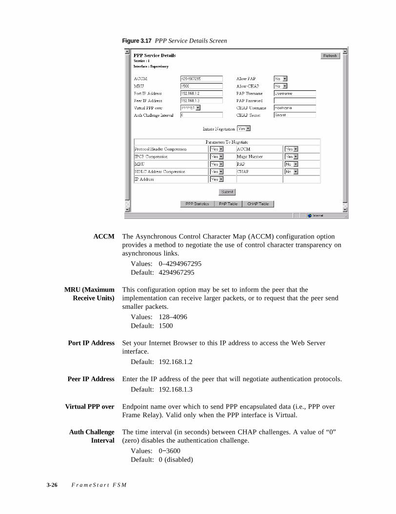
Figure 3.17 PPP Service Details Screen
ACCM The Asynchronous Control Character Map (ACCM) configuration option provides a method to negotiate the use of control character transparency on asynchronous links.
Values: 0–4294967295Default: 4294967295
MRU (MaximumReceive Units)
This configuration option may be set to inform the peer that the implementation can receive larger packets, or to request that the peer send smaller packets.
Values: 128–4096Default: 1500
Port IP Address Set your Internet Browser to this IP address to access the Web Server interface.
Default: 192.168.1.2
Peer IP Address Enter the IP address of the peer that will negotiate authentication protocols.
Default: 192.168.1.3
Virtual PPP over Endpoint name over which to send PPP encapsulated data (i.e., PPP over Frame Relay). Valid only when the PPP interface is Virtual.
Auth ChallengeInterval
The time interval (in seconds) between CHAP challenges. A value of “0” (zero) disables the authentication challenge.
Values: 0−3600Default: 0 (disabled)
3-26 F r a m e S t a r t F S M
Allow PAP This parameter is used to allow the peer to negotiate for PAP.
Values: No, YesDefault: No
Allow CHAP This parameter is used to allow the peer to negotiate for CHAP.
Values: No, YesDefault: No
PAP Username This field is used (along with the PAP Password) to log on to the peer. Type the appropriate PAP Username in this field.
Values: (user established)Default: Username
PAP Password This field is used to enter the password necessary to log on to the peer under a given PAP Username.
Values: (user established)Default: (none)
CHAP Username This field is used (along with the CHAP Secret) to challenge the peer. Type the appropriate CHAP Hostname in this field.
Values: (user established)Default: Hostname
CHAP Secret This field is used to enter the Secret (i.e., password) necessary to challenge the peer.
Values: (user established)Default: Secret
Initiate Negotiation Determines whether the port actively negotiates with the peer site or passively waits for negotiation requests.
Values: Yes, NoDefault: Yes
Parameters To Negotiate
The table displayed near the bottom of the PPP Service Details screen shows which parameters are set to be negotiated. You can specify which parameters should be negotiated by clicking on the pull-down menu next to each parameter and selecting the desired option. The table below describes the parameters that can be negotiated.
Parameter Description
Protocol Header Compression
Provides a method to compress PPP protocol headers.Default = Yes
IPCP (IP Control Protocol) Compression
Configures, enables, and disables the IP protocol modules on both ends of a point-to-point link. Default = Yes
W e b S e r v e r I n t e r f a c e 3-27
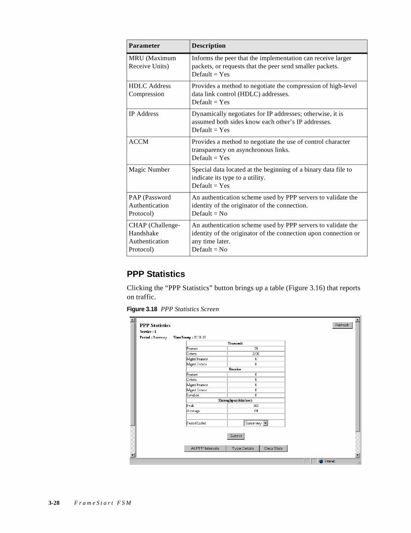
PPP Statistics
Clicking the “PPP Statistics” button brings up a table (Figure 3.16) that reports on traffic.
Figure 3.18 PPP Statistics Screen
MRU (Maximum Receive Units)
Informs the peer that the implementation can receive larger packets, or requests that the peer send smaller packets.Default = Yes
HDLC Address Compression
Provides a method to negotiate the compression of high-level data link control (HDLC) addresses.Default = Yes
IP Address Dynamically negotiates for IP addresses; otherwise, it is assumed both sides know each other’s IP addresses.Default = Yes
ACCM Provides a method to negotiate the use of control character transparency on asynchronous links. Default = Yes
Magic Number Special data located at the beginning of a binary data file to indicate its type to a utility.Default = Yes
PAP (Password Authentication Protocol)
An authentication scheme used by PPP servers to validate the identity of the originator of the connection. Default = No
CHAP (Challenge-Handshake Authentication Protocol)
An authentication scheme used by PPP servers to validate the identity of the originator of the connection upon connection or any time later.Default = No
Parameter Description
3-28 F r a m e S t a r t F S M
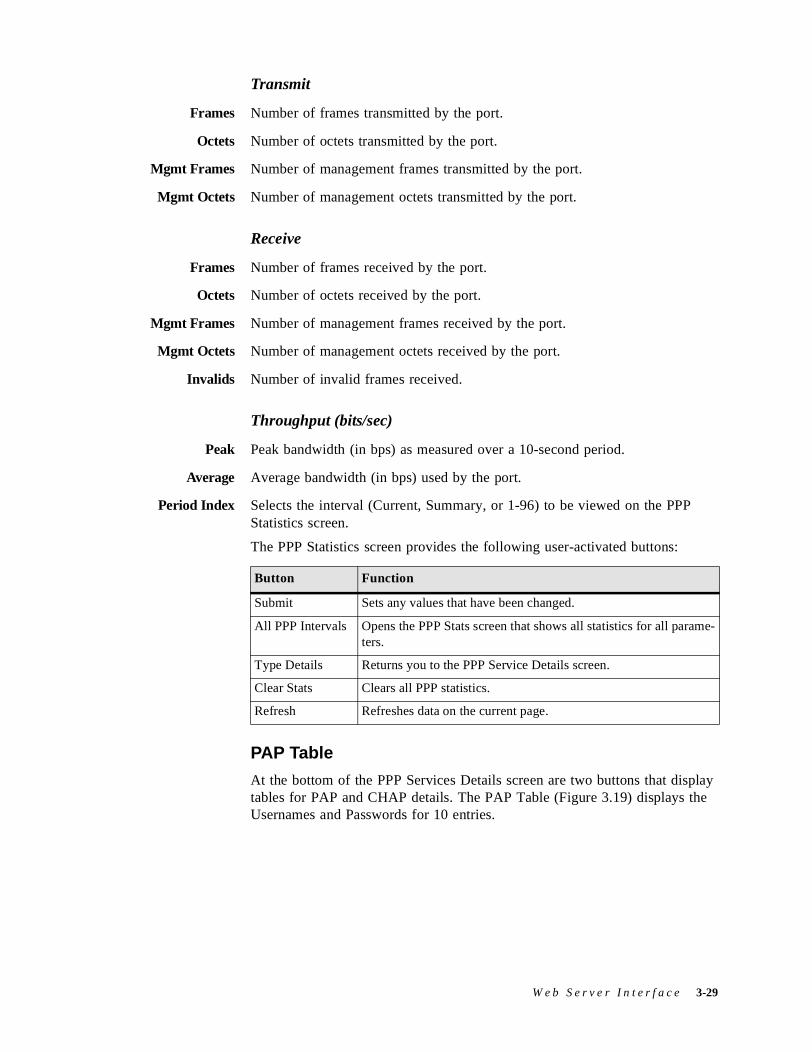
Transmit
Frames Number of frames transmitted by the port.
Octets Number of octets transmitted by the port.
Mgmt Frames Number of management frames transmitted by the port.
Mgmt Octets Number of management octets transmitted by the port.
Receive
Frames Number of frames received by the port.
Octets Number of octets received by the port.
Mgmt Frames Number of management frames received by the port.
Mgmt Octets Number of management octets received by the port.
Invalids Number of invalid frames received.
Throughput (bits/sec)
Peak Peak bandwidth (in bps) as measured over a 10-second period.
Average Average bandwidth (in bps) used by the port.
Period Index Selects the interval (Current, Summary, or 1-96) to be viewed on the PPP Statistics screen.
The PPP Statistics screen provides the following user-activated buttons:
PAP Table
At the bottom of the PPP Services Details screen are two buttons that display tables for PAP and CHAP details. The PAP Table (Figure 3.19) displays the Usernames and Passwords for 10 entries.
Button Function
Submit Sets any values that have been changed.
All PPP Intervals Opens the PPP Stats screen that shows all statistics for all parame-ters.
Type Details Returns you to the PPP Service Details screen.
Clear Stats Clears all PPP statistics.
Refresh Refreshes data on the current page.
W e b S e r v e r I n t e r f a c e 3-29
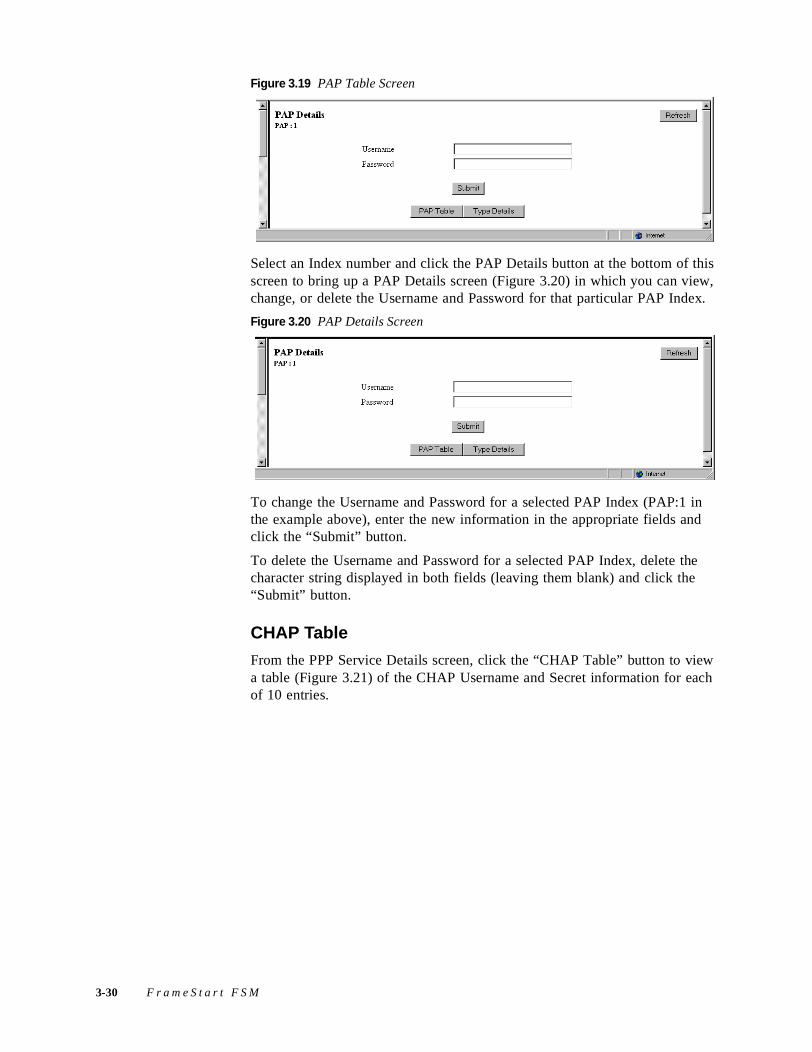
Figure 3.19 PAP Table Screen
Select an Index number and click the PAP Details button at the bottom of this screen to bring up a PAP Details screen (Figure 3.20) in which you can view, change, or delete the Username and Password for that particular PAP Index.
Figure 3.20 PAP Details Screen
To change the Username and Password for a selected PAP Index (PAP:1 in the example above), enter the new information in the appropriate fields and click the “Submit” button.
To delete the Username and Password for a selected PAP Index, delete the character string displayed in both fields (leaving them blank) and click the “Submit” button.
CHAP Table
From the PPP Service Details screen, click the “CHAP Table” button to view a table (Figure 3.21) of the CHAP Username and Secret information for each of 10 entries.
3-30 F r a m e S t a r t F S M
Figure 3.21 CHAP Table Screen
Select an Index number and click the “CHAP Details” button at the bottom of this screen to bring up a screen in which you can change the Username and Secret for that particular CHAP Index.
Figure 3.22 CHAP Details Screen
To change the Username and Secret for a selected CHAP Index, enter the new information in the appropriate fields and click the “Submit” button.
10/100 Ethernet (IP Services) ScreenThe IP Services screen and Ethernet Stats screens are described earlier in this chapter on page 3-13 and page 3-15, respectively.
ApplicationsThe Applications screens describe configuration tables and statistics that do not map to a specific service or interface.
W e b S e r v e r I n t e r f a c e 3-31
Endpoint Table ScreenThe Endpoint Table (Figure 3.23) describes all endpoints terminating in the unit; user-activated buttons are provided to view the Endpoint Details, Endpoint Service Details, and Endpoint DLCI Details screens. The unit will automatically learn all DLCIs from the Network side and relay that information on the Serial side with default values.
The Endpoint Table and its corresponding DLCIs will be saved in the configuration database only after at least one endpoint parameter has been changed and submitted in the Endpoint Details screen (page 3-33).
NOTICE: The Endpoint Table and its corresponding DLCIs will be saved in the configuration database only after at least one endpoint parameter has been changed and submitted in the Endpoint Details Screen on page 3-33.
NOTICE: Endpoint names of the form PPP-Sn are reserved by the system. These system-generated endpoints cannot be modified.
Figure 3.23 Endpoint Table Screen
For most applications, the Endpoint Table and DLCI Table will not have to be modified. Modification would be necessary, however, to configure remote in-band management. (See In Band management on page 3-36.)
Endpoint Details Screen
The Endpoint Details screen (Figure 3.24) provides you with access to the configuration parameters described in the paragraphs below.
3-32 F r a m e S t a r t F S M
Figure 3.24 Endpoint Details Screen
Name When the unit learns a new DLCI, it creates an endpoint entry and a DLCI entry if they are not already configured. The endpoint’s Name will automatically be assigned as “Dynamic”; however, this name can (and most likely should) be changed to reflect a remote location name. Submitting a changed Name parameter will cause the endpoint entry and its corresponding DLCI entry to be saved in the configuration database.
Value: A string of up to 11 characters Default: None
CAUTION: When configuring endpoints, the name you assign each endpoint in the Name parameter field must be unique within the unit.
Service The Service Index number (from the Service Table) on which this DLCI was found or configured.
Values: Displays the currently active Services (by index number) or the Service(s) on which the DLCI was discovered.
Default: 0
DLCI The DLCI number.
Values: 0–1023Default: 0
Forward Endpoint By default, each DLCI is switched to its pair service in the Service Table using the same DLCI number. If this endpoint has to be switched to a different DLCI or a different service, the endpoint index of the destination must be configured here.
For most applications, you will not need to set this parameter.
Values: 0–256Default: 0
W e b S e r v e r I n t e r f a c e 3-33
Backup Endpoint If this DLCI has an alternative endpoint to switch to in case this DLCI becomes inactive, you would configure the endpoint index of this alternative endpoint here.
For most applications, you will not need to set this parameter.
Values: 0–256Default: 0
SLP ReferenceEndpoint
This is the reference endpoint index to use for the Service Level Agreement parameters. As most applications have the same SLAs for all DLCIs, they need to be configured in only one DLCI entry. All SLA parameters can then be copied from the endpoint index of this configured DLCI. If no SLP reference endpoint is configured and the DLCI SLA parameters are not configured, the values in the Frame Relay Service Details will be used (default CIR, EB, enforcement).
Most applications do not need to set this parameter.
Values: 0–256Default: 0
Remote IP Address If this FSM unit is to be used to manage a remote FSM unit, the IP address of the remote FSM unit must be configured here. This DLCI can be used for management only, or for management and actual data.
If this parameter is set, a PC connected to the LAN interface of this FSM can reach a remote FSM through this DLCI. The remote IP address must be part of a different IP network from the local FSM, and the local FSM's IP address must be configured into the PC. This way, local and remote FSMs can be reached regardless of the availability of the routers connected at the back of the FSMs.
Values: IP addressDefault: 0.0.0.0
Remote IP Mask If the Remote IP Address is set, the Remote IP Mask must also be set.
Values: IP addressDefault: 0.0.0.0
Type If data received from this DLCI has to be switched to its corresponding destination port, the type must be set to “Switched.” The type should be set to “Local” for any DLCI that is used for management purposes only.
Values: Switched, LocalDefault: Switched
New DLCI This field is used to create a new DLCI if it is not already configured. To create a new DLCI, enter a valid DLCI number in the field and click the “Submit” button. The new DLCI number will be reflected in the DLCI field of the Endpoint Details screen.
3-34 F r a m e S t a r t F S M
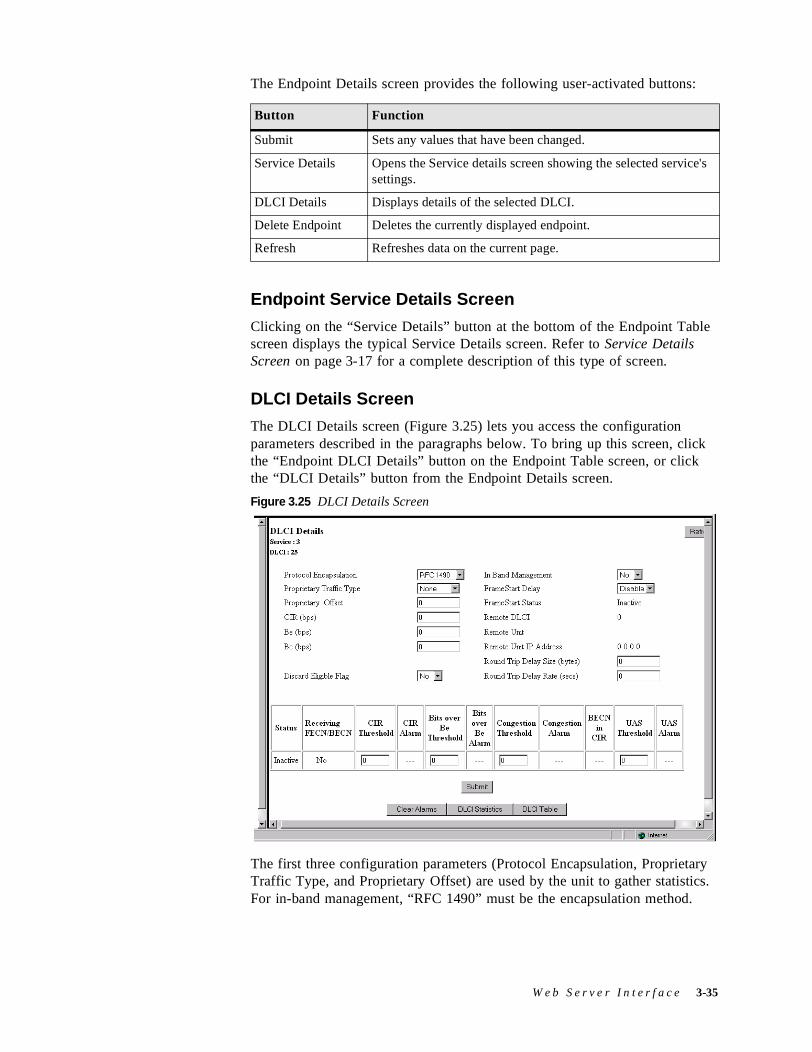
The Endpoint Details screen provides the following user-activated buttons:
Endpoint Service Details Screen
Clicking on the “Service Details” button at the bottom of the Endpoint Table screen displays the typical Service Details screen. Refer to Service Details Screen on page 3-17 for a complete description of this type of screen.
DLCI Details Screen
The DLCI Details screen (Figure 3.25) lets you access the configuration parameters described in the paragraphs below. To bring up this screen, click the “Endpoint DLCI Details” button on the Endpoint Table screen, or click the “DLCI Details” button from the Endpoint Details screen.
Figure 3.25 DLCI Details Screen
The first three configuration parameters (Protocol Encapsulation, Proprietary Traffic Type, and Proprietary Offset) are used by the unit to gather statistics. For in-band management, “RFC 1490” must be the encapsulation method.
Button Function
Submit Sets any values that have been changed.
Service Details Opens the Service details screen showing the selected service's settings.
DLCI Details Displays details of the selected DLCI.
Delete Endpoint Deletes the currently displayed endpoint.
Refresh Refreshes data on the current page.
W e b S e r v e r I n t e r f a c e 3-35
Protocol Encapsulation Type of encapsulation used by the FRAD/Router connected to the unit.
Values: RFC 1490, ProprietaryDefault: RFC 1490
Proprietary TrafficType
When Protocol Encapsulation is set for “Proprietary,” the Proprietary Traffic Type parameter defines which protocol is encapsulated.
Values: IP, IPX, Ethertype, NoneDefault: None
Proprietary Offset When Protocol Encapsulation is set for “Proprietary,” the Proprietary Offset parameter defines the number of octets after the frame relay header where the proprietary traffic type starts.
Values: 0–64Default: 0
CIR (bps) If a Committed Information Rate is configured here, its value will be used instead of the default CIR of the frame relay service.
Values: 0–1536000Default: 0
Be (bps) If an Excess Burst Rate is configured here, its value will be used instead of the default Be of the frame relay service.
Values: 0–1536000Default: 0
Bc (bps) If CIR enforcement is configured to “Yes,” the unit will throttle the Committed Burst down to this value when frames are received with the BECN bit set.
Values: 0–1536000Default: 0
Discard Eligible Flag If this parameter is set to “Yes” and CIR enforcement is also set to “Yes,” the unit will set the Discard Eligible (DE) bit for frames sent over CIR.
Values: Yes, NoDefault: No
In Band management If the unit is to be used as a gateway to reach a remote FSM through this DLCI, this parameter should be set to “Yes,” and the remote IP address and Mask should be configured in the corresponding endpoint.
Values: Yes, NoDefault: No
FrameStart Delay If this parameter is set to “Enable,” the unit will send FrameStart discovery and delay frames on this DLCI, and will report the state of the remote FSx unit. It will also send SOS frames when the FRAD/router connected to this unit goes inactive.
Values: Enable, DisableDefault: Enable if Auto Discovery is set to “Yes”; Disable otherwise
3-36 F r a m e S t a r t F S M
FrameStart Status If the remote unit is a Verilink FSx product and FrameStart Auto Discovery is enabled, the FrameStart Status field will show the status of the remote unit. The status is “Active” if both the local and remote DLCIs are active and the remote unit answers to the discovery frames sent by this unit. The status is “SOS” if the remote unit is active but the FRAD/Router connected to it is inactive. The status is “Inactive” in all other cases.
Values: Active, Inactive, SOSDefault: Inactive
Remote DLCI If the remote unit is a Verilink FSx product, and FrameStart Auto Discovery is enabled, this displays the DLCI number used on the remote end of this DLCI.
Values: 0−1023Default: 0
Remote Unit If the remote unit is a Verilink FSx product, and FrameStart Auto Discovery is enabled, this parameter gives the first three digits of the unit ID configured on the remote end of this DLCI.
Values: 000 - 999Default: 000
Round Trip Delay Size Specifies the frame size (in bytes) of packets making the round-trip. If the Round Trip Delay Size is not configured, the Frame Relay Details values will be used.
Round Trip Delay Rate Specifies the rate (in seconds) at which Round Trip Delay packets are sent. If the Round Trip Delay Rate is not configured, the Frame Relay Details values will be used.
DLCI Status TableThe bottom portion of the screen shows a table detailing the actual status of this DLCI and alarm threshold information as indicated below.
Status If this DLCI is up, the status will be “Active”; otherwise, the status will be “Inactive.”
Values: Active, InactiveDefault: Inactive
Receiving FECN/BECN
When a frame is received with congestion bit set, this parameter is set to “Yes.” It is set back to “No” when a frame is received without congestion bit set.
Values: Yes, NoDefault: No
CIR Threshold Sets the Tx over CIR alarm threshold. This threshold is the number of bits per second in excess of CIR during a 15-minute interval. Setting this field to “0” (zero) disables the alarm.
W e b S e r v e r I n t e r f a c e 3-37
CIR Alarm Reports if the Tx over CIR threshold has been exceeded.
Bits Over Be Threshold Sets the Tx over the excess burst alarm threshold. This threshold is the number of bits per second in excess of CIR + Be during a 15-minute interval. Setting this field to “0” (zero) disables the alarm.
Bits Over Be Alarm Reports if the Tx over Be threshold has been exceeded.
Congestion Threshold Sets the Rx Congestion alarm threshold. This threshold is the number of frames received with BECN/FECN. Setting this field to “0” (zero) disables the alarm.
Congestion Alarm Reports if the Rx Congestion threshold has been exceeded.
BECN with CIR Reports if Backward Explicit Congestion Notification (BECN) has been received within CIR.
UAS Threshold Sets the Unavailable Seconds (UAS) alarm threshold. This threshold is the number of seconds passed that the DLCI is unavailable. Setting this field to “0” (zero) disables the alarm.
UAS Alarm Reports if the UAS threshold has been exceeded.
The DLCI Details screen provides the user-activated buttons defined below.
DLCI Statistics Screen
Clicking the “DLCI Statistics” button on the Endpoint DLCI Details screen will display the following screen:
Button Function
Submit Sets and activates newly defined DLCI parameters.
Clear Alarms Clears all DLCI alarms.
DLCI Statistics Displays a table of the statistics for this DLCI.
DLCI Table Displays a table of all DLCIs on a specific frame relay service, with their state and alarm conditions.
Refresh Refreshes data on the current page.
3-38 F r a m e S t a r t F S M
Figure 3.26 DLCI Statistics Screen
There are 96 15-minute buckets (sampled every second) available for DLCI statistics. If the unit is powered on at 01:00 PM, the first interval will be completed at 01:15 PM; subsequent intervals would be completed at xx:30, xx:45, xx:00 and xx:15. Interval 1 is always the latest (most recent) interval, and interval 96 will always be the oldest.
The DLCI Statistics screen in the preceding figure shows a summary that includes all 96 buckets. You can choose to see the statistics for any given bucket by selecting the desired Period Index from the pull-down menu and clicking the “Submit” button. Alternatively, you can display all intervals at once by clicking the “All DLCI Intervals” button beneath the table. The MIB (ipadv2.mib) describes each available statistic. “FDR” on the screen above refers to Frame Delivery Ratio, which is the ration of successful frame receptions to attempted frame transmissions. “DDR” refers to Data Delivery Ratio or the ratio of successful payload bytes received to attempted payload bytes transmitted. “DE,” or Discard Eligible, refers to the data that is first eligible to be discarded when network congestion occurs.
DLCI Table Screen
Clicking the “DLCI Table” button on the Endpoint DLCI Details screen will display a table of all DLCIs on a specific frame relay service along with their state and alarm conditions.
W e b S e r v e r I n t e r f a c e 3-39
Figure 3.27 DLCI Table Screen
NOTICE: The DLCI Table and DLCI Details screens are available from the both the Endpoint Table and the Frame Relay Service Details screens.
SNMP Details ScreenThe unit detects and reports T1 network alarms and provides several options for reporting them, one of which is SNMP traps. When a network alarm occurs, the unit sends a trap message to as many as eight destinations on your network. The unit will report each alarm by transmitting an SNMP “trap” to each non-zero Trap IP address. The SNMP Details screen (Figure 3.28) lets you configure the SNMP parameters described in the paragraphs below.
Figure 3.28 SNMP Details Screen
Read Community Accepts a character string identifying the group authorized to perform read operations. The default setting is “Public.”
Write Community Accepts a character string identifying the group authorized to perform write operations. The default setting is “Private.”
Trap Community Accepts a character string, which is included in SNMP traps generated by the unit. The default setting is “Public.”
3-40 F r a m e S t a r t F S M
Trap IP Address Accepts the IP address of a network device where alarm reporting traps are to be sent.
The unit detects and reports T1 network alarms and provides several options for reporting them, one of which is SNMP traps. When a network alarm occurs, the unit sends a trap message to as many as eight destinations on the user’s network. The unit will report each alarm by transmitting an SNMP “trap” to each non-zero Trap IP address.
Diagnostics ScreenThe Diagnostics screen (Figure 3.29) provides a table for viewing the current settings for the test and maintenance functions performed on the available interfaces. This screen shows an upper-level view of all the interfaces so you can see if any port is under test, and if so, view the results. You may change Diagnostic parameters through the Test Details screen, which is accessed from a button on the Diagnostics screen. The properties of the Diagnostics table are described in the paragraphs below.
Figure 3.29 Diagnostics Screen
Description Describes the type of interface selected for testing.
Loop Type Describes the type of loop test (if any) performed on the selected interface.
Setting Displays the bandwidth on which you wish to perform the BERT.
Pattern Specifies the pattern to be transmitted during a test for the selected port.
Length Displays the length of time for which the test should run for the selected interface.
State Displays the current test state for the selected interface.
Elapsed Time Displays the time elapsed since a timed test began or, if completed, the total test time.
W e b S e r v e r I n t e r f a c e 3-41
BE Displays the total number of bit errors detected since the test began or since error statistics were last cleared.
ES (Errored Seconds) Displays the number of asynchronous errored seconds that have been detected since the test began or since error statistics were last cleared. This parameter includes bit error seconds and sync loss seconds.
%EFS Displays what percent of the total BERT time ran error free. This ratio is derived from the number of error-free seconds divided by the number of seconds accumulated in Elapsed Time.
Test Details Screens
The Test Details screens let you set some test parameters and view other read-only parameters. This screen is also used to initiate a BERT or Loop Test. The Network Interface Test Details screen is shown in Figure 3.30 and the Serial Interface Test Details screen is shown in Figure 3.31.
Figure 3.30 Network Interface Test Details Screen
BERT Table on Network Interface Test Details Screen
The BERT table lets you set the test parameters described below.
Setting Displays the bandwidth on which you wish to perform the BERT. The available values for this parameter depend on which interface is selected.
Values: Idle, Channels 1–24, Net, Use ServiceDefault: Net
Service Selects the channels with a service to BERT. (Refer to Figure 3.12 on page 3-16.) (This parameter only appears on Network screens.)
3-42 F r a m e S t a r t F S M
Channel Rate Sets the bit rate to BERT for each selected channel. If “Νx64K” is selected, the ones density requirements of the T1 network line must be ensured. If “Νx56K” is selected, ones density for the selected DS0 channel is maintained.
Values: Nx56K, Nx64KDefault: Nx64K
BERT Pattern Specifies the pattern to be transmitted during a test for the selected port.
Values: Marks, QRSS, 511, 2047, 215, SpacesDefault: QRSS
NOTICE: The 215 pattern is the ITU (European) version, not the ANSI version.
Test Duration Specifies the length of time for which the test should run for the selected port.
Values: 15 min, 30 min, 1 hour, 24 hours, ContinuousDefault: Continuous
You can also view the following read-only parameters from this screen:
Pattern Sync Displays the state of pattern sync during a test. If no test is in progress, “No Test” is displayed. If a test is active, but the receiver is not in pattern sync, “No Sync” is displayed. If the receiver is in pattern sync, “In Sync” is displayed.
Elapsed Time Displays the time elapsed since a timed test began or, if completed, the total test time.
Bit Errors Displays the total number of bit errors detected since the test began or since error statistics were cleared.
Errored Seconds Displays the number of asynchronous errored seconds that have been detected since the test began or since error statistics were last cleared.
%EFS Displays the percentage of time that the test ran error-free. This ratio is derived from the number of error-free seconds divided by the number of seconds accumulated in Elapsed Time.
Loop Table on Network Interface Test Details Screen
The types of tests available for you to choose from depend on the currently selected interface. For the Network interface, the Loop table provided near the bottom of the Test Details screen lets you specify the type of Loop test to be performed.
Values: No Test (Loop Down), payload loopback (PLB), line loopback (LLB), maintenance loopback (MLB), Far PLB, Far LLB
Default: No Test (Loop Down)
W e b S e r v e r I n t e r f a c e 3-43
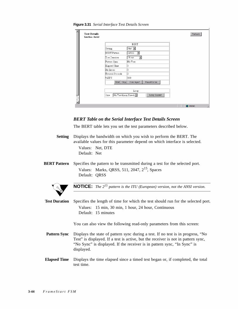
Figure 3.31 Serial Interface Test Details Screen
BERT Table on the Serial Interface Test Details Screen
The BERT table lets you set the test parameters described below.
Setting Displays the bandwidth on which you wish to perform the BERT. The available values for this parameter depend on which interface is selected.
Values: Net, DTEDefault: Net
BERT Pattern Specifies the pattern to be transmitted during a test for the selected port.
Values: Marks, QRSS, 511, 2047, 215, SpacesDefault: QRSS
NOTICE: The 215 pattern is the ITU (European) version, not the ANSI version.
Test Duration Specifies the length of time for which the test should run for the selected port.
Values: 15 min, 30 min, 1 hour, 24 hour, ContinuousDefault: 15 minutes
You can also view the following read-only parameters from this screen:
Pattern Sync Displays the state of pattern sync during a test. If no test is in progress, “No Test” is displayed. If a test is active, but the receiver is not in pattern sync, “No Sync” is displayed. If the receiver is in pattern sync, “In Sync” is displayed.
Elapsed Time Displays the time elapsed since a timed test began or, if completed, the total test time.
3-44 F r a m e S t a r t F S M
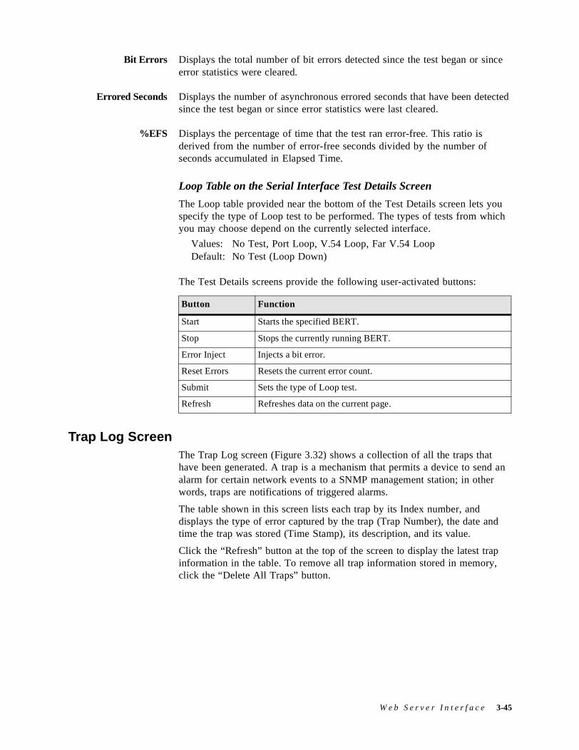
Bit Errors Displays the total number of bit errors detected since the test began or since error statistics were cleared.
Errored Seconds Displays the number of asynchronous errored seconds that have been detected since the test began or since error statistics were last cleared.
%EFS Displays the percentage of time that the test ran error-free. This ratio is derived from the number of error-free seconds divided by the number of seconds accumulated in Elapsed Time.
Loop Table on the Serial Interface Test Details Screen
The Loop table provided near the bottom of the Test Details screen lets you specify the type of Loop test to be performed. The types of tests from which you may choose depend on the currently selected interface.
Values: No Test, Port Loop, V.54 Loop, Far V.54 LoopDefault: No Test (Loop Down)
The Test Details screens provide the following user-activated buttons:
Trap Log ScreenThe Trap Log screen (Figure 3.32) shows a collection of all the traps that have been generated. A trap is a mechanism that permits a device to send an alarm for certain network events to a SNMP management station; in other words, traps are notifications of triggered alarms.
The table shown in this screen lists each trap by its Index number, and displays the type of error captured by the trap (Trap Number), the date and time the trap was stored (Time Stamp), its description, and its value.
Click the “Refresh” button at the top of the screen to display the latest trap information in the table. To remove all trap information stored in memory, click the “Delete All Traps” button.
Button Function
Start Starts the specified BERT.
Stop Stops the currently running BERT.
Error Inject Injects a bit error.
Reset Errors Resets the current error count.
Submit Sets the type of Loop test.
Refresh Refreshes data on the current page.
W e b S e r v e r I n t e r f a c e 3-45
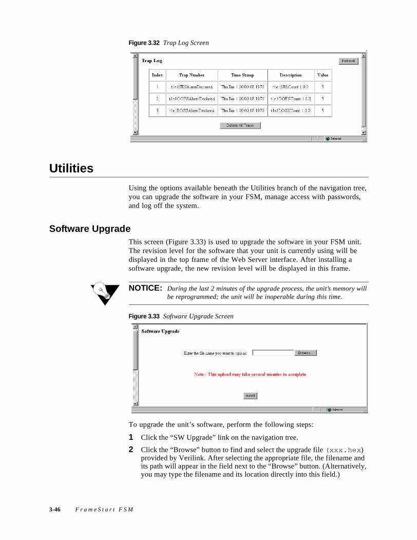
Figure 3.32 Trap Log Screen
UtilitiesUsing the options available beneath the Utilities branch of the navigation tree, you can upgrade the software in your FSM, manage access with passwords, and log off the system.
Software UpgradeThis screen (Figure 3.33) is used to upgrade the software in your FSM unit. The revision level for the software that your unit is currently using will be displayed in the top frame of the Web Server interface. After installing a software upgrade, the new revision level will be displayed in this frame.
NOTICE: During the last 2 minutes of the upgrade process, the unit’s memory will be reprogrammed; the unit will be inoperable during this time.
Figure 3.33 Software Upgrade Screen
To upgrade the unit’s software, perform the following steps:
1 Click the “SW Upgrade” link on the navigation tree.
2 Click the “Browse” button to find and select the upgrade file (xxx.hex) provided by Verilink. After selecting the appropriate file, the filename and its path will appear in the field next to the “Browse” button. (Alternatively, you may type the filename and its location directly into this field.)
3-46 F r a m e S t a r t F S M
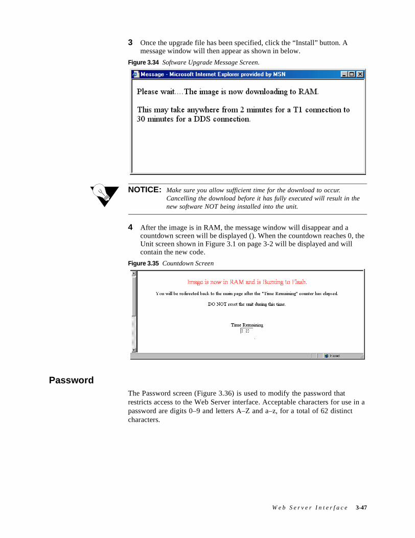
3 Once the upgrade file has been specified, click the “Install” button. A message window will then appear as shown in below.
Figure 3.34 Software Upgrade Message Screen.
NOTICE: Make sure you allow sufficient time for the download to occur. Cancelling the download before it has fully executed will result in the new software NOT being installed into the unit.
4 After the image is in RAM, the message window will disappear and a countdown screen will be displayed (). When the countdown reaches 0, the Unit screen shown in Figure 3.1 on page 3-2 will be displayed and will contain the new code.
Figure 3.35 Countdown Screen
PasswordThe Password screen (Figure 3.36) is used to modify the password that restricts access to the Web Server interface. Acceptable characters for use in a password are digits 0–9 and letters A–Z and a–z, for a total of 62 distinct characters.
W e b S e r v e r I n t e r f a c e 3-47
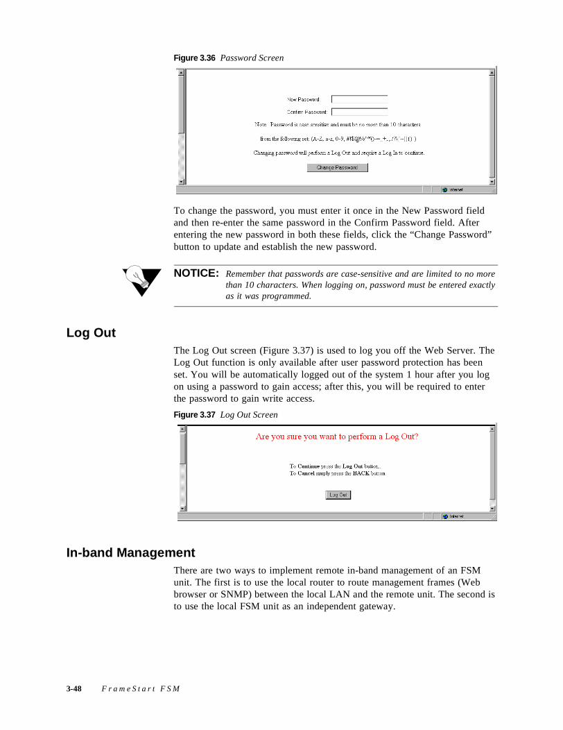
Figure 3.36 Password Screen
To change the password, you must enter it once in the New Password field and then re-enter the same password in the Confirm Password field. After entering the new password in both these fields, click the “Change Password” button to update and establish the new password.
NOTICE: Remember that passwords are case-sensitive and are limited to no more than 10 characters. When logging on, password must be entered exactly as it was programmed.
Log OutThe Log Out screen (Figure 3.37) is used to log you off the Web Server. The Log Out function is only available after user password protection has been set. You will be automatically logged out of the system 1 hour after you log on using a password to gain access; after this, you will be required to enter the password to gain write access.
Figure 3.37 Log Out Screen
In-band ManagementThere are two ways to implement remote in-band management of an FSM unit. The first is to use the local router to route management frames (Web browser or SNMP) between the local LAN and the remote unit. The second is to use the local FSM unit as an independent gateway.
3-48 F r a m e S t a r t F S M
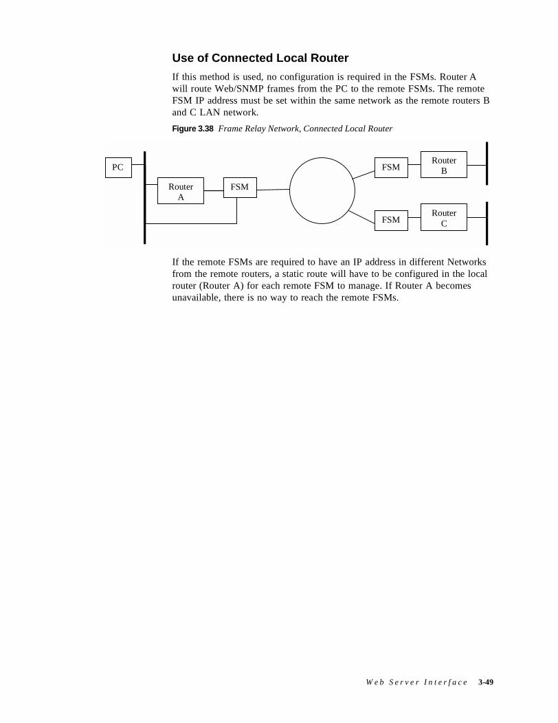
Use of Connected Local Router
If this method is used, no configuration is required in the FSMs. Router A will route Web/SNMP frames from the PC to the remote FSMs. The remote FSM IP address must be set within the same network as the remote routers B and C LAN network.
Figure 3.38 Frame Relay Network, Connected Local Router
If the remote FSMs are required to have an IP address in different Networks from the remote routers, a static route will have to be configured in the local router (Router A) for each remote FSM to manage. If Router A becomes unavailable, there is no way to reach the remote FSMs.
PC
RouterA
FSM
FSM
FSMRouter
C
RouterB
W e b S e r v e r I n t e r f a c e 3-49

3-50 F r a m e S t a r t F S M
C H A P T E R
4CHAPTER 4VT100 INTERFACE
IntroductionThis chapter describes the menus and options associated with the FrameStart FSM’s VT100 interface. The screens displayed throughout this chapter were accessed through a TELNET session.
NOTICE: The material presented in this chapter follows the order in which the screens are presented in the VT100 interface. However, because the parameters you specify in the Service Table attach protocols to interfaces, you must configure the Service Table first. (See Service Table Screen on page 4-17.) You will not be able to allocate channels (see Channel Table Details Screen on page 4-19) until the Service Table has been configured.
Accessing the VT100 InterfaceYou can access the VT100 interface locally via the Supervisory port or remotely through a TELNET session. To access the VT100 screens locally, verify the Supervisory type is “tty” and the Supervisory port speed matches the terminal emulation program that’s being used. (Port speeds supported include the following: 1200, 2400, 4800, 9600, 19200, 38400, 57600, and 115200 bps.) You can access the VT100 interface remotely by opening a TELNET session, entering the unit’s IP address, and connecting to the unit.
Screen ComponentsThe VT100 terminal screens have several components common to all screens (see below). These components include the device type, which is centered on the screen, the software and hardware revision numbers (upper left), the date and time (upper right), the menu title (“Main” in the figure below), and the serial number under which the unit is operating. Except for the Main screen shown in Figure 4.2, the screen captures throughout this chapter show only the configuration portion of the screen and not the screen components.
V T 1 0 0 I n t e r f a c e 4-1
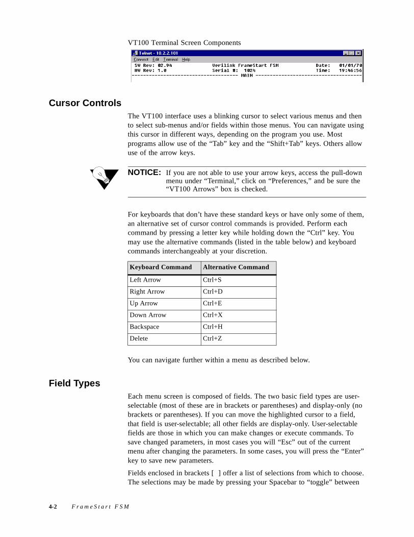
VT100 Terminal Screen Components
Cursor ControlsThe VT100 interface uses a blinking cursor to select various menus and then to select sub-menus and/or fields within those menus. You can navigate using this cursor in different ways, depending on the program you use. Most programs allow use of the “Tab” key and the “Shift+Tab” keys. Others allow use of the arrow keys.
NOTICE: If you are not able to use your arrow keys, access the pull-down menu under “Terminal,” click on “Preferences,” and be sure the “VT100 Arrows” box is checked.
For keyboards that don’t have these standard keys or have only some of them, an alternative set of cursor control commands is provided. Perform each command by pressing a letter key while holding down the “Ctrl” key. You may use the alternative commands (listed in the table below) and keyboard commands interchangeably at your discretion.
You can navigate further within a menu as described below.
Field TypesEach menu screen is composed of fields. The two basic field types are user-selectable (most of these are in brackets or parentheses) and display-only (no brackets or parentheses). If you can move the highlighted cursor to a field, that field is user-selectable; all other fields are display-only. User-selectable fields are those in which you can make changes or execute commands. To save changed parameters, in most cases you will “Esc” out of the current menu after changing the parameters. In some cases, you will press the “Enter” key to save new parameters.
Fields enclosed in brackets [ ] offer a list of selections from which to choose. The selections may be made by pressing your Spacebar to “toggle” between
Keyboard Command Alternative Command
Left Arrow Ctrl+S
Right Arrow Ctrl+D
Up Arrow Ctrl+E
Down Arrow Ctrl+X
Backspace Ctrl+H
Delete Ctrl+Z
4-2 F r a m e S t a r t F S M
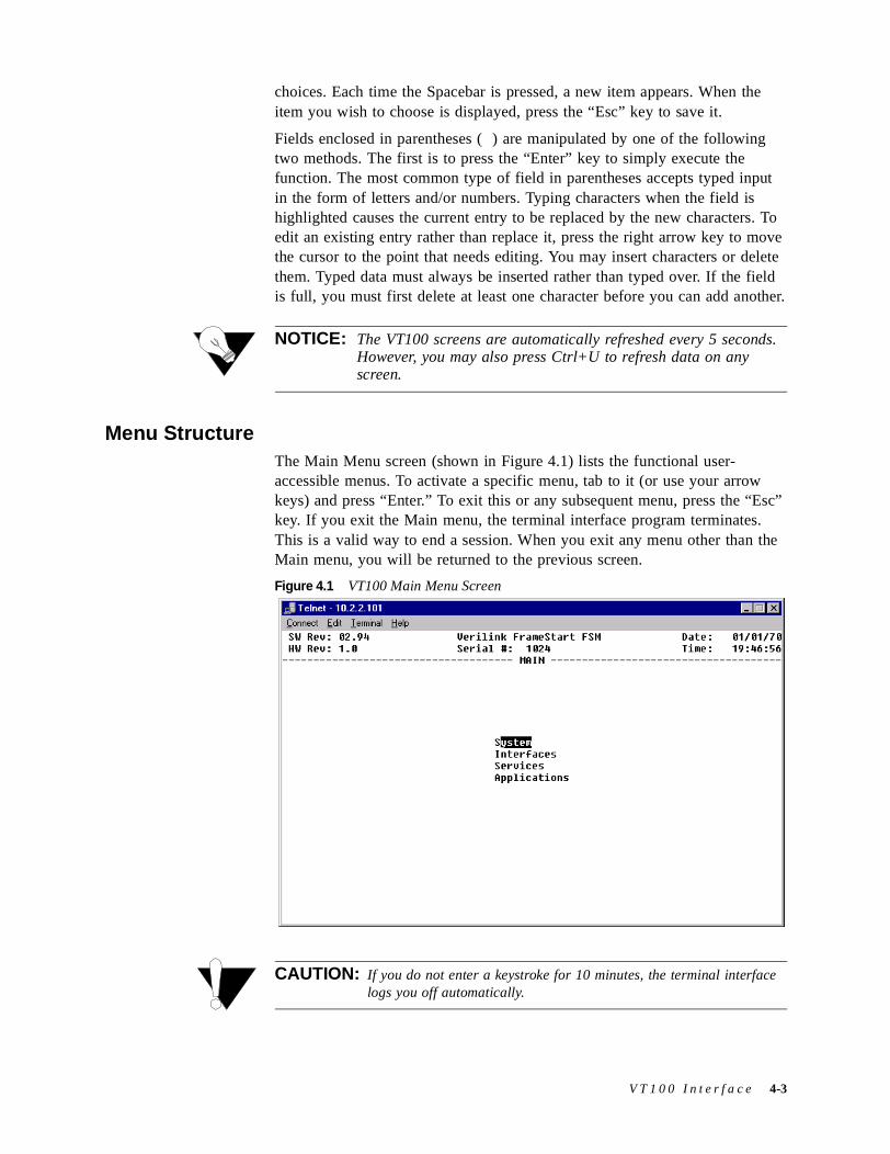
choices. Each time the Spacebar is pressed, a new item appears. When the item you wish to choose is displayed, press the “Esc” key to save it.
Fields enclosed in parentheses ( ) are manipulated by one of the following two methods. The first is to press the “Enter” key to simply execute the function. The most common type of field in parentheses accepts typed input in the form of letters and/or numbers. Typing characters when the field is highlighted causes the current entry to be replaced by the new characters. To edit an existing entry rather than replace it, press the right arrow key to move the cursor to the point that needs editing. You may insert characters or delete them. Typed data must always be inserted rather than typed over. If the field is full, you must first delete at least one character before you can add another.
NOTICE: The VT100 screens are automatically refreshed every 5 seconds. However, you may also press Ctrl+U to refresh data on any screen.
Menu StructureThe Main Menu screen (shown in Figure 4.1) lists the functional user-accessible menus. To activate a specific menu, tab to it (or use your arrow keys) and press “Enter.” To exit this or any subsequent menu, press the “Esc” key. If you exit the Main menu, the terminal interface program terminates. This is a valid way to end a session. When you exit any menu other than the Main menu, you will be returned to the previous screen.
Figure 4.1 VT100 Main Menu Screen
CAUTION: If you do not enter a keystroke for 10 minutes, the terminal interface logs you off automatically.
V T 1 0 0 I n t e r f a c e 4-3
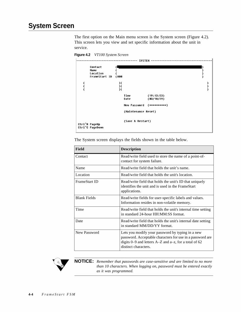
System ScreenThe first option on the Main menu screen is the System screen (Figure 4.2). This screen lets you view and set specific information about the unit in service.
Figure 4.2 VT100 System Screen
The System screen displays the fields shown in the table below.
NOTICE: Remember that passwords are case-sensitive and are limited to no more than 10 characters. When logging on, password must be entered exactly as it was programmed.
Field Description
Contact Read/write field used to store the name of a point-of-contact for system failure.
Name Read/write field that holds the unit’s name.
Location Read/write field that holds the unit's location.
FrameStart ID Read/write field that holds the unit's ID that uniquely identifies the unit and is used in the FrameStart applications.
Blank Fields Read/write fields for user-specific labels and values. Information resides in non-volatile memory.
Time Read/write field that holds the unit's internal time setting in standard 24-hour HH:MM:SS format.
Date Read/write field that holds the unit's internal date setting in standard MM/DD/YY format.
New Password Lets you modify your password by typing in a new password. Acceptable characters for use in a password are digits 0–9 and letters A–Z and a–z, for a total of 62 distinct characters.
4-4 F r a m e S t a r t F S M
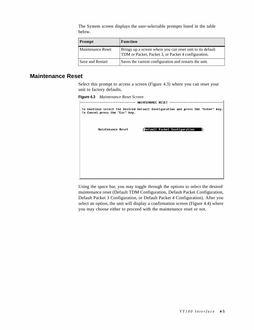
The System screen displays the user-selectable prompts listed in the table below.
Maintenance ResetSelect this prompt to access a screen (Figure 4.3) where you can reset your unit to factory defaults.
Figure 4.3 Maintenance Reset Screen
Using the space bar, you may toggle through the options to select the desired maintenance reset (Default TDM Configuration, Default Packet Configuration, Default Packet 3 Configuration, or Default Packet 4 Configuration). After you select an option, the unit will display a confirmation screen (Figure 4.4) where you may choose either to proceed with the maintenance reset or not.
Prompt Function
Maintenance Reset Brings up a screen where you can reset unit to its default TDM or Packet, Packet 3, or Packet 4 configuration.
Save and Restart Saves the current configuration and restarts the unit.
V T 1 0 0 I n t e r f a c e 4-5
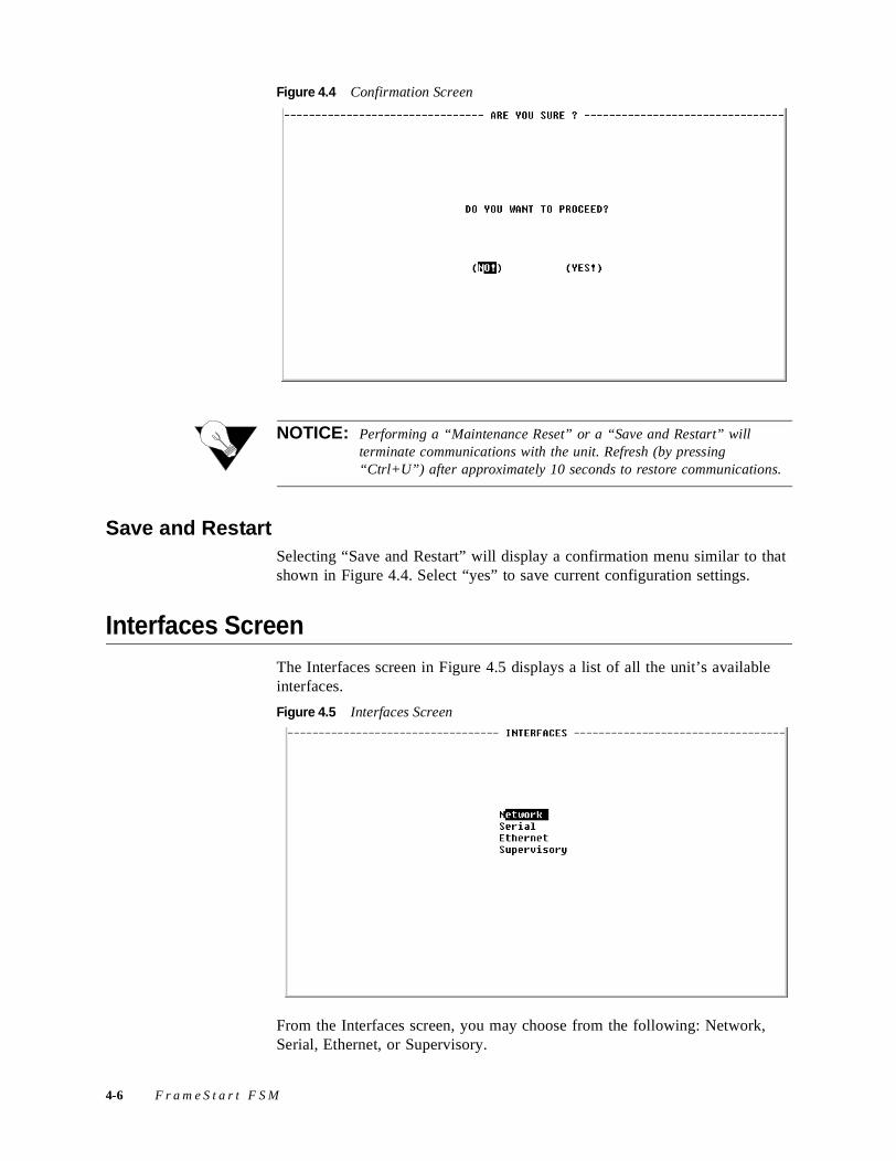
Figure 4.4 Confirmation Screen
NOTICE: Performing a “Maintenance Reset” or a “Save and Restart” will terminate communications with the unit. Refresh (by pressing “Ctrl+U”) after approximately 10 seconds to restore communications.
Save and RestartSelecting “Save and Restart” will display a confirmation menu similar to that shown in Figure 4.4. Select “yes” to save current configuration settings.
Interfaces ScreenThe Interfaces screen in Figure 4.5 displays a list of all the unit’s available interfaces.
Figure 4.5 Interfaces Screen
From the Interfaces screen, you may choose from the following: Network, Serial, Ethernet, or Supervisory.
4-6 F r a m e S t a r t F S M
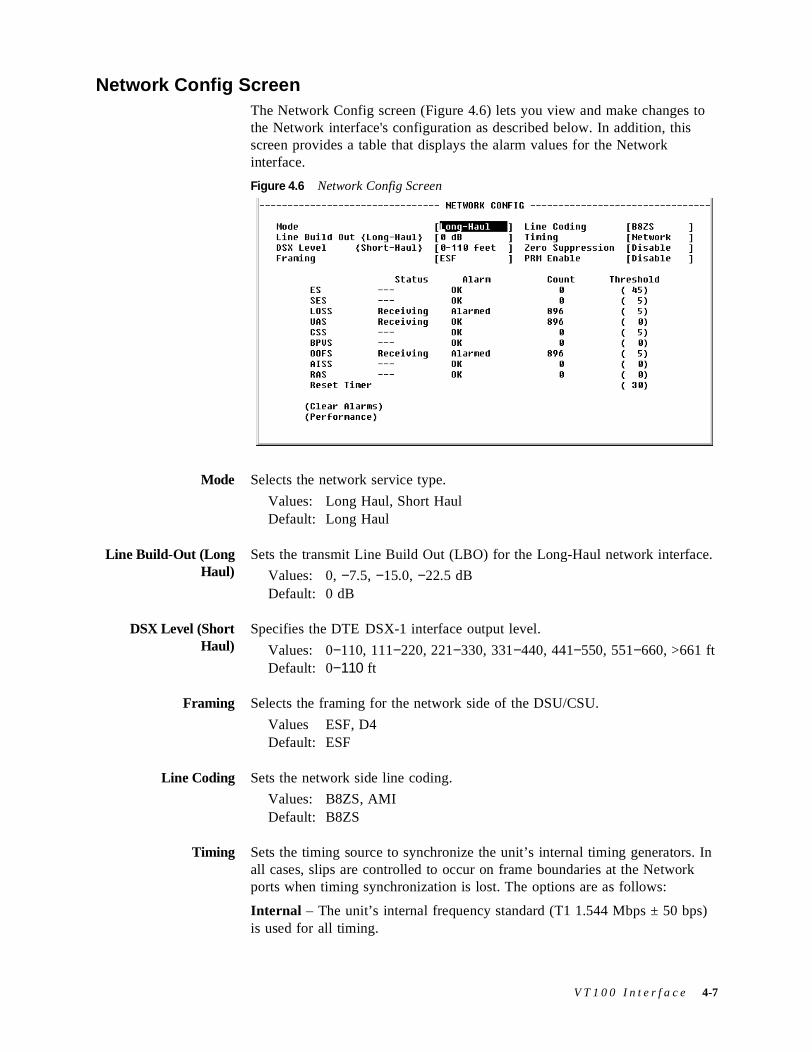
Network Config Screen The Network Config screen (Figure 4.6) lets you view and make changes to the Network interface's configuration as described below. In addition, this screen provides a table that displays the alarm values for the Network interface.
Figure 4.6 Network Config Screen
Mode Selects the network service type.
Values: Long Haul, Short HaulDefault: Long Haul
Line Build-Out (LongHaul)
Sets the transmit Line Build Out (LBO) for the Long-Haul network interface.
Values: 0, −7.5, −15.0, −22.5 dBDefault: 0 dB
DSX Level (ShortHaul)
Specifies the DTE DSX-1 interface output level.
Values: 0−110, 111−220, 221−330, 331−440, 441−550, 551−660, >661 ftDefault: 0−110 ft
Framing Selects the framing for the network side of the DSU/CSU.
Values ESF, D4Default: ESF
Line Coding Sets the network side line coding.
Values: B8ZS, AMIDefault: B8ZS
Timing Sets the timing source to synchronize the unit’s internal timing generators. In all cases, slips are controlled to occur on frame boundaries at the Network ports when timing synchronization is lost. The options are as follows:
Internal – The unit’s internal frequency standard (T1 1.544 Mbps ± 50 bps) is used for all timing.
V T 1 0 0 I n t e r f a c e 4-7
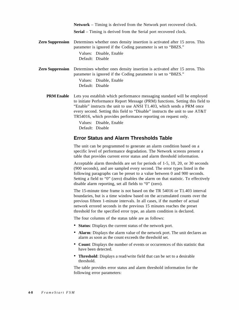
Network – Timing is derived from the Network port recovered clock.
Serial – Timing is derived from the Serial port recovered clock.
Zero Suppression Determines whether ones density insertion is activated after 15 zeros. This parameter is ignored if the Coding parameter is set to “B8ZS.”
Values: Disable, EnableDefault: Disable
Zero Suppression Determines whether ones density insertion is activated after 15 zeros. This parameter is ignored if the Coding parameter is set to “B8ZS.”
Values: Disable, EnableDefault: Disable
PRM Enable Lets you establish which performance messaging standard will be employed to initiate Performance Report Message (PRM) functions. Setting this field to “Enable” instructs the unit to use ANSI T1.403, which sends a PRM once every second. Setting this field to “Disable” instructs the unit to use AT&T TR54016, which provides performance reporting on request only.
Values: Disable, EnableDefault: Disable
Error Status and Alarm Thresholds Table
The unit can be programmed to generate an alarm condition based on a specific level of performance degradation. The Network screens present a table that provides current error status and alarm threshold information.
Acceptable alarm thresholds are set for periods of 1-5, 10, 20, or 30 seconds (900 seconds), and are sampled every second. The error types listed in the following paragraphs can be preset to a value between 0 and 900 seconds. Setting a field to “0” (zero) disables the alarm on that statistic. To effectively disable alarm reporting, set all fields to “0” (zero).
The 15-minute time frame is not based on the TR 54016 or T1.403 interval boundaries, but is a time window based on the accumulated counts over the previous fifteen 1-minute intervals. In all cases, if the number of actual network errored seconds in the previous 15 minutes reaches the preset threshold for the specified error type, an alarm condition is declared.
The four columns of the status table are as follows:
• Status: Displays the current status of the network port.
• Alarm: Displays the alarm value of the network port. The unit declares an alarm as soon as the count exceeds the threshold set.
• Count: Displays the number of events or occurrences of this statistic that have been detected.
• Threshold: Displays a read/write field that can be set to a desirable threshold.
The table provides error status and alarm threshold information for the following error parameters:
4-8 F r a m e S t a r t F S M
ES Sets the Errored Seconds (ES) threshold. An ES is a 1-second period in which at least one logic error occurred. The default value is 45 seconds.
SES Sets the Severely Errored Seconds (SES) threshold. An SES is a 1-second period in which at least 320 CRC errors or one Out-of-Frame (OOF) error occurred. The default value is 5 seconds.
LOSS Sets the Loss of Signal Seconds (LOSS) threshold. A LOSS is 1-second period in which the E1 received signal is interrupted. The default value is 5 seconds.
UAS Sets the Unavailable Seconds (UAS) threshold. A UAS is a 1-second period in which consecutive severely errored seconds cause an unavailable state. The default is 0 seconds (Disabled).
CSS Sets the Controlled Slip Seconds (CSS) threshold. The default is 0 seconds (Disabled).
BPVS Sets the Bipolar Violation Errored Seconds (BPVS) threshold. A BPVS is a 1-second period in which at least one bipolar violation occurred. The default is 0 seconds (Disabled).
OOFS Sets the Out of Frame Seconds (OOFS) threshold. An OOFS is a 1-second period in which a frame sync loss occurred. The default value is 5 seconds.
AISS Sets the Alarm Indication Signal Seconds (AISS) threshold. An AIS is a 1-second period when unframed all ones are received. The default is 0 seconds (Disabled).
RAS Sets the Remote Alarm Seconds (RAS) threshold. An RAS is generated by the terminal equipment when an improper signal is received from the facility (or upon receipt of unframed all ones). The default is 0 seconds (Disabled).
Reset Timer Sets the Reset Timer threshold. This read/write field is used to establish the contiguous number of seconds that an alarm parameter must be clear before the alarm is reset. Applicable values range from 000 through 900. A value of “000” means the alarm will never be reset.
The Network Config screen provides the user-selectable prompts described in the table below.
Prompt Function
Clear Alarms Resets the alarm conditions related to the Network and counts to zero.
V T 1 0 0 I n t e r f a c e 4-9
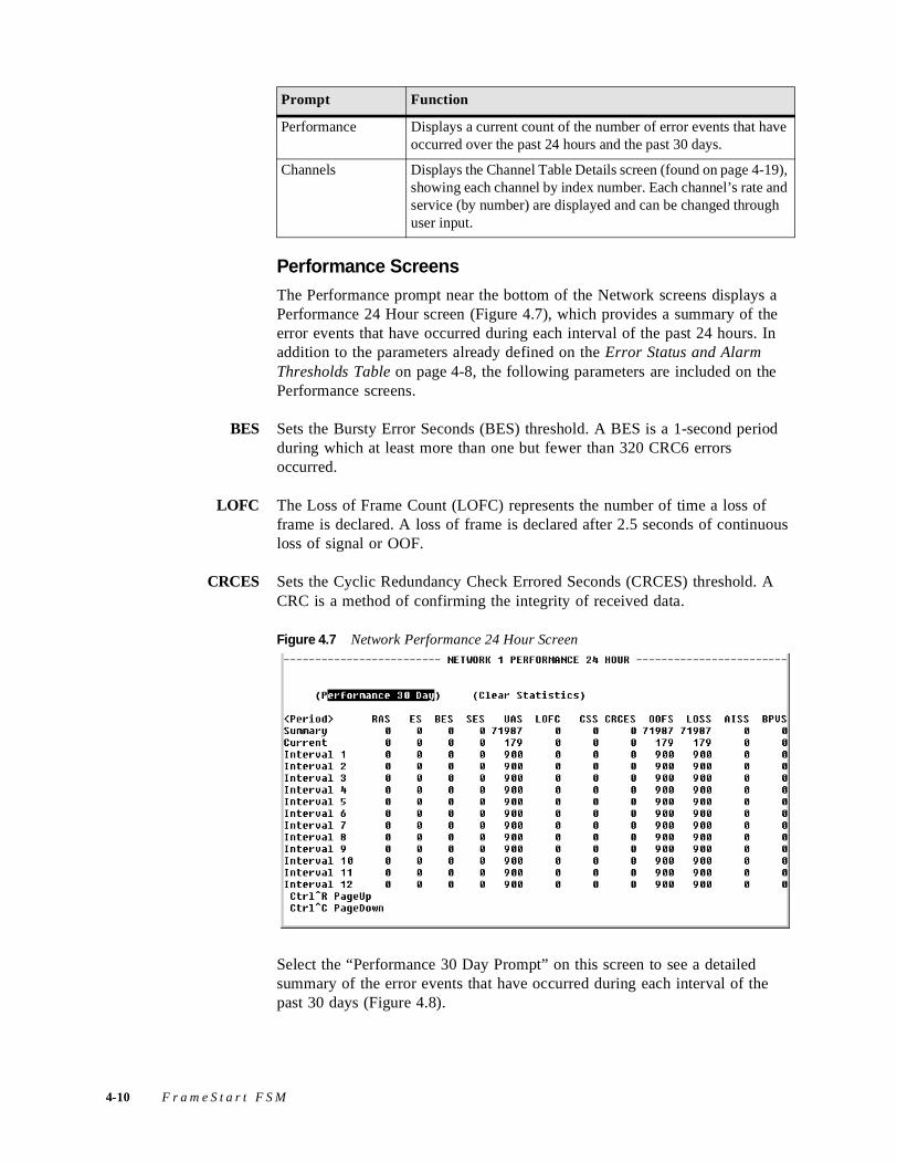
Performance ScreensThe Performance prompt near the bottom of the Network screens displays a Performance 24 Hour screen (Figure 4.7), which provides a summary of the error events that have occurred during each interval of the past 24 hours. In addition to the parameters already defined on the Error Status and Alarm Thresholds Table on page 4-8, the following parameters are included on the Performance screens.
BES Sets the Bursty Error Seconds (BES) threshold. A BES is a 1-second period during which at least more than one but fewer than 320 CRC6 errors occurred.
LOFC The Loss of Frame Count (LOFC) represents the number of time a loss of frame is declared. A loss of frame is declared after 2.5 seconds of continuous loss of signal or OOF.
CRCES Sets the Cyclic Redundancy Check Errored Seconds (CRCES) threshold. A CRC is a method of confirming the integrity of received data.
Figure 4.7 Network Performance 24 Hour Screen
Select the “Performance 30 Day Prompt” on this screen to see a detailed summary of the error events that have occurred during each interval of the past 30 days (Figure 4.8).
Performance Displays a current count of the number of error events that have occurred over the past 24 hours and the past 30 days.
Channels Displays the Channel Table Details screen (found on page 4-19), showing each channel by index number. Each channel’s rate and service (by number) are displayed and can be changed through user input.
Prompt Function
4-10 F r a m e S t a r t F S M
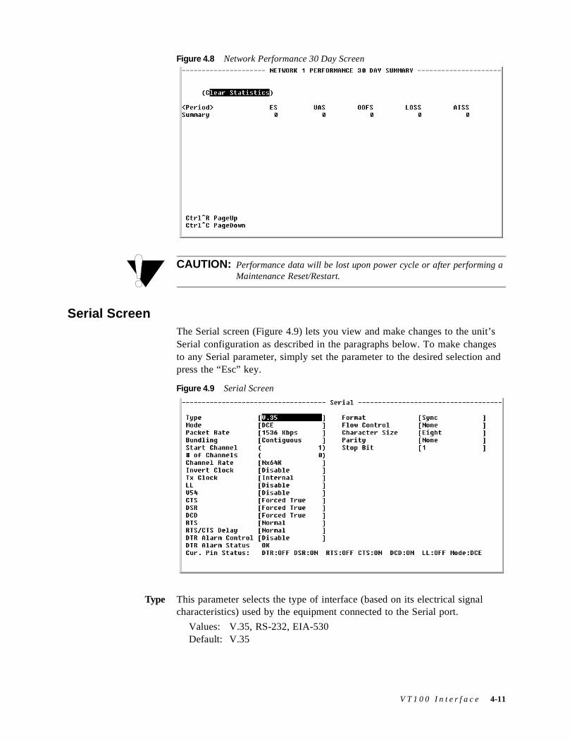
Figure 4.8 Network Performance 30 Day Screen
CAUTION: Performance data will be lost upon power cycle or after performing a Maintenance Reset/Restart.
Serial ScreenThe Serial screen (Figure 4.9) lets you view and make changes to the unit’s Serial configuration as described in the paragraphs below. To make changes to any Serial parameter, simply set the parameter to the desired selection and press the “Esc” key.
Figure 4.9 Serial Screen
Type This parameter selects the type of interface (based on its electrical signal characteristics) used by the equipment connected to the Serial port.
Values: V.35, RS-232, EIA-530Default: V.35
V T 1 0 0 I n t e r f a c e 4-11
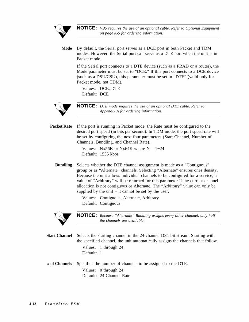
NOTICE: V.35 requires the use of an optional cable. Refer to Optional Equipment on page A-5 for ordering information.
Mode By default, the Serial port serves as a DCE port in both Packet and TDM modes. However, the Serial port can serve as a DTE port when the unit is in Packet mode.
If the Serial port connects to a DTE device (such as a FRAD or a router), the Mode parameter must be set to “DCE.” If this port connects to a DCE device (such as a DSU/CSU), this parameter must be set to “DTE” (valid only for Packet mode, not TDM).
Values: DCE, DTEDefault: DCE
NOTICE: DTE mode requires the use of an optional DTE cable. Refer to Appendix A for ordering information.
Packet Rate If the port is running in Packet mode, the Rate must be configured to the desired port speed (in bits per second). In TDM mode, the port speed rate will be set by configuring the next four parameters (Start Channel, Number of Channels, Bundling, and Channel Rate).
Values: Nx56K or Nx64K where N = 1−24Default: 1536 kbps
Bundling Selects whether the DTE channel assignment is made as a “Contiguous” group or as “Alternate” channels. Selecting “Alternate” ensures ones density. Because the unit allows individual channels to be configured for a service, a value of “Arbitrary” will be returned for this parameter if the current channel allocation is not contiguous or Alternate. The “Arbitrary” value can only be supplied by the unit − it cannot be set by the user.
Values: Contiguous, Alternate, ArbitraryDefault: Contiguous
NOTICE: Because “Alternate” Bundling assigns every other channel, only half the channels are available.
Start Channel Selects the starting channel in the 24-channel DS1 bit stream. Starting with the specified channel, the unit automatically assigns the channels that follow.
Values: 1 through 24Default: 1
# of Channels Specifies the number of channels to be assigned to the DTE.
Values: 0 through 24Default: 24 Channel Rate
4-12 F r a m e S t a r t F S M
Channel Rate The unit can operate at any data rate that is a multiple of 56 or 64 kbps. If “Νx64K” is selected, the ones density requirements of the T1 network line must be ensured. If “Νx56K” is selected, ones density for the selected DS0 channel is maintained.
Values: Nx56K, Nx64KDefault: Nx64K
NOTICE: Start Channel, Number of Channels, and Channel Rate cannot be changed if Bundling is not also changed from “Arbitrary.”
Invert Clock In DTE Packet mode, this parameter changes the clock edge of the transmitted data. The Invert Clock parameter is only available for use in DTE mode.
Values: Disable, EnableDefault: Disable
Tx Clock Selects the clock the unit uses to sample the data transmitted from the DTE. When set to “Internal,” the data is sampled directly with the transmit data clock that is also supplied to the DTE as Transmit Clock. The “External” option uses the external clock from the DTE.
Values: Internal, ExternalDefault: Internal
NOTICE: The “External” option is valid only in Packet mode.
LL The Local Loopback (LL) parameter can be set to “Enable” or “Disable.” Selecting “Enable” allows the unit to go into Local Loop when the LL pin on the Serial port goes high. The unit exits the loop when the LL pin goes low. If you select “Disable,” the unit ignores the LL pin on the Serial port.
Values: Disable, EnableDefault: Disable
NOTICE: For more information on pin assignments, refer to Network Interface Pin Assignments shown on page A-8.
V54 Selecting “Enable” allows the unit to respond to in-band V.54 loop codes. If you select “Disable,” the unit ignores these codes.
Values: Disable, EnableDefault: Disable
CTS The Clear to Send (CTS) parameter can be set to “Forced True,” “Forced False,” or “Internal.” If this parameter is set to “Internal,” the CTS control lead follows the RTS control lead from the DTE after a delay of a duration
V T 1 0 0 I n t e r f a c e 4-13

established by the RTS/CTS Delay parameter (see RTS/CTS Delay on page 4-14).
Values: Forced True, Forced False, InternalDefault: Forced True
DSR Data Set Ready (DSR) can be set to “Forced True,” “Forced False,” or “Internal.” The “Internal” option sets DSR “On” if the port is enabled and “Off” if the port is disabled.
Values: Forced True, Forced False, InternalDefault: Forced True
DCD The Data Carrier Detect (DCD) parameter can be set to “Forced True,” “Forced False,” or “Internal.” If set to “Internal,” DCD is “On” when network carrier is being received from the remote end, and is “Off” when network carrier is not being received from the far end.
Values: Forced True, Forced False, InternalDefault: Forced True
RTS The Request to Send (RTS) parameter determines the source from which the unit reads the RTS signal status. If set to “Normal,” the unit gets RTS from the DTE on the Serial interface. If set to “Forced True,” RTS is always perceived as “On.”
Values: Normal, Forced TrueDefault: Normal
RTS/CTS Delay The Request to Send/Clear to Send (RTS/CTS) parameter determines how long the unit waits before it changes the level of CTS to match RTS when the CTS parameter is set to “Internal.”
Values: Normal (~30 ms delay), Long (~100 ms delay)Default: Normal
DTR Alarm Control Lets you set DTR Alarm Control parameters.
Values: Enable, DisableDefault: Disable
DTR Alarm Status Lets you view the current DTR Alarm status.
Format Selects the port’s operating mode.
Values: Sync, AsyncDefault: Sync
Flow Control Selects the type of flow control to be used if the port is asynchronous.
Values: None, Xon/Xoff, RTS/CTSDefault: None
Character Size Selects the number of bits required to make up one asynchronous character.
Values: Five, Six, Seven, EightDefault: Eight
4-14 F r a m e S t a r t F S M
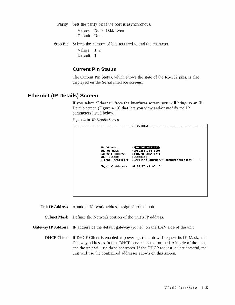
Parity Sets the parity bit if the port is asynchronous.
Values: None, Odd, EvenDefault: None
Stop Bit Selects the number of bits required to end the character.
Values: 1, 2Default: 1
Current Pin Status
The Current Pin Status, which shows the state of the RS-232 pins, is also displayed on the Serial interface screens.
Ethernet (IP Details) ScreenIf you select “Ethernet” from the Interfaces screen, you will bring up an IP Details screen (Figure 4.10) that lets you view and/or modify the IP parameters listed below.
Figure 4.10 IP Details Screen
Unit IP Address A unique Network address assigned to this unit.
Subnet Mask Defines the Network portion of the unit’s IP address.
Gateway IP Address IP address of the default gateway (router) on the LAN side of the unit.
DHCP Client If DHCP Client is enabled at power-up, the unit will request its IP, Mask, and Gateway addresses from a DHCP server located on the LAN side of the unit, and the unit will use these addresses. If the DHCP request is unsuccessful, the unit will use the configured addresses shown on this screen.
V T 1 0 0 I n t e r f a c e 4-15
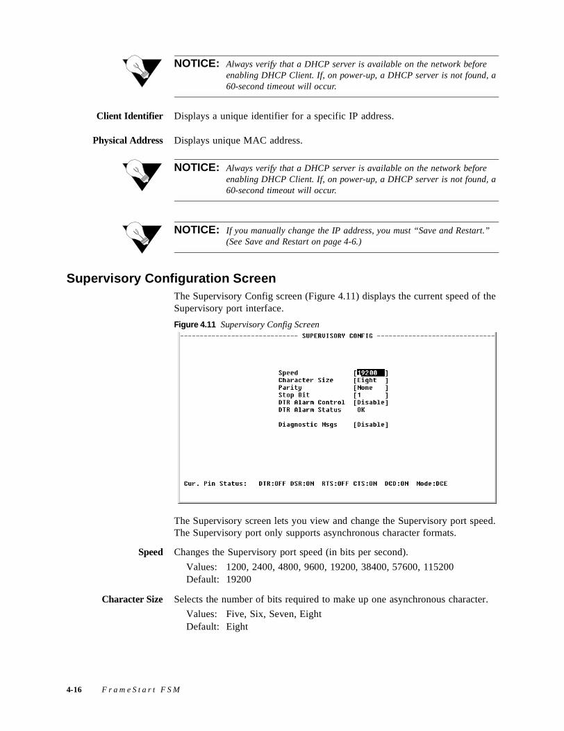
NOTICE: Always verify that a DHCP server is available on the network before enabling DHCP Client. If, on power-up, a DHCP server is not found, a 60-second timeout will occur.
Client Identifier Displays a unique identifier for a specific IP address.
Physical Address Displays unique MAC address.
NOTICE: Always verify that a DHCP server is available on the network before enabling DHCP Client. If, on power-up, a DHCP server is not found, a 60-second timeout will occur.
NOTICE: If you manually change the IP address, you must “Save and Restart.” (See Save and Restart on page 4-6.)
Supervisory Configuration ScreenThe Supervisory Config screen (Figure 4.11) displays the current speed of the Supervisory port interface.
Figure 4.11 Supervisory Config Screen
The Supervisory screen lets you view and change the Supervisory port speed. The Supervisory port only supports asynchronous character formats.
Speed Changes the Supervisory port speed (in bits per second).
Values: 1200, 2400, 4800, 9600, 19200, 38400, 57600, 115200Default: 19200
Character Size Selects the number of bits required to make up one asynchronous character.
Values: Five, Six, Seven, EightDefault: Eight
4-16 F r a m e S t a r t F S M
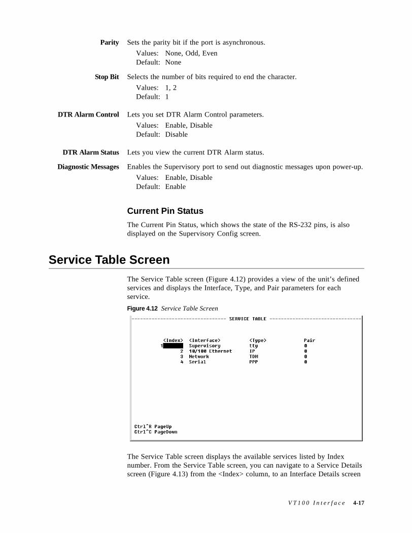
Parity Sets the parity bit if the port is asynchronous.
Values: None, Odd, EvenDefault: None
Stop Bit Selects the number of bits required to end the character.
Values: 1, 2Default: 1
DTR Alarm Control Lets you set DTR Alarm Control parameters.
Values: Enable, DisableDefault: Disable
DTR Alarm Status Lets you view the current DTR Alarm status.
Diagnostic Messages Enables the Supervisory port to send out diagnostic messages upon power-up.
Values: Enable, DisableDefault: Enable
Current Pin Status
The Current Pin Status, which shows the state of the RS-232 pins, is also displayed on the Supervisory Config screen.
Service Table ScreenThe Service Table screen (Figure 4.12) provides a view of the unit’s defined services and displays the Interface, Type, and Pair parameters for each service.
Figure 4.12 Service Table Screen
The Service Table screen displays the available services listed by Index number. From the Service Table screen, you can navigate to a Service Details screen (Figure 4.13) from the <Index> column, to an Interface Details screen
V T 1 0 0 I n t e r f a c e 4-17
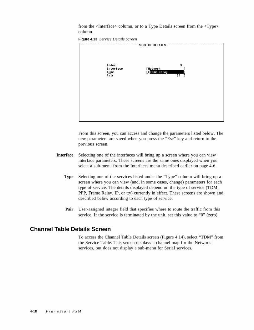
from the <Interface> column, or to a Type Details screen from the <Type> column.
Figure 4.13 Service Details Screen
From this screen, you can access and change the parameters listed below. The new parameters are saved when you press the “Esc” key and return to the previous screen.
Interface Selecting one of the interfaces will bring up a screen where you can view interface parameters. These screens are the same ones displayed when you select a sub-menu from the Interfaces menu described earlier on page 4-6.
Type Selecting one of the services listed under the “Type” column will bring up a screen where you can view (and, in some cases, change) parameters for each type of service. The details displayed depend on the type of service (TDM, PPP, Frame Relay, IP, or tty) currently in effect. These screens are shown and described below according to each type of service.
Pair User-assigned integer field that specifies where to route the traffic from this service. If the service is terminated by the unit, set this value to “0” (zero).
Channel Table Details ScreenTo access the Channel Table Details screen (Figure 4.14), select “TDM” from the Service Table. This screen displays a channel map for the Network services, but does not display a sub-menu for Serial services.
4-18 F r a m e S t a r t F S M
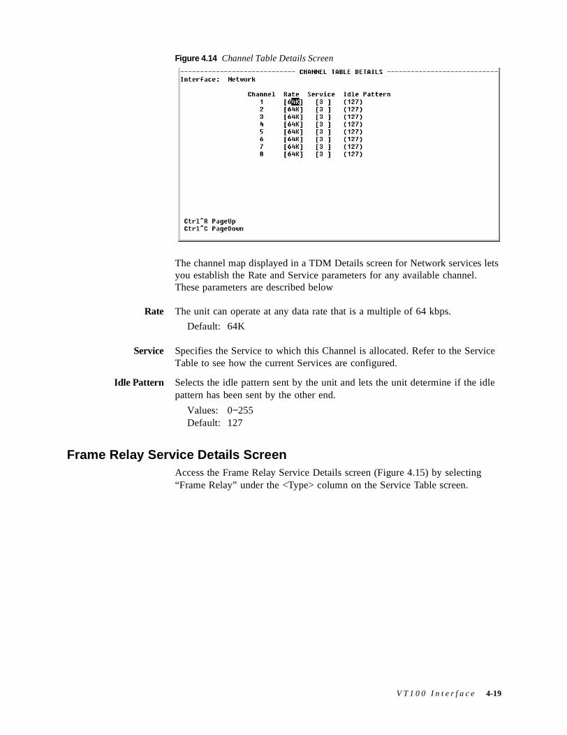
Figure 4.14 Channel Table Details Screen
The channel map displayed in a TDM Details screen for Network services lets you establish the Rate and Service parameters for any available channel. These parameters are described below
Rate The unit can operate at any data rate that is a multiple of 64 kbps.
Default: 64K
Service Specifies the Service to which this Channel is allocated. Refer to the Service Table to see how the current Services are configured.
Idle Pattern Selects the idle pattern sent by the unit and lets the unit determine if the idle pattern has been sent by the other end.
Values: 0−255Default: 127
Frame Relay Service Details ScreenAccess the Frame Relay Service Details screen (Figure 4.15) by selecting “Frame Relay” under the <Type> column on the Service Table screen.
V T 1 0 0 I n t e r f a c e 4-19
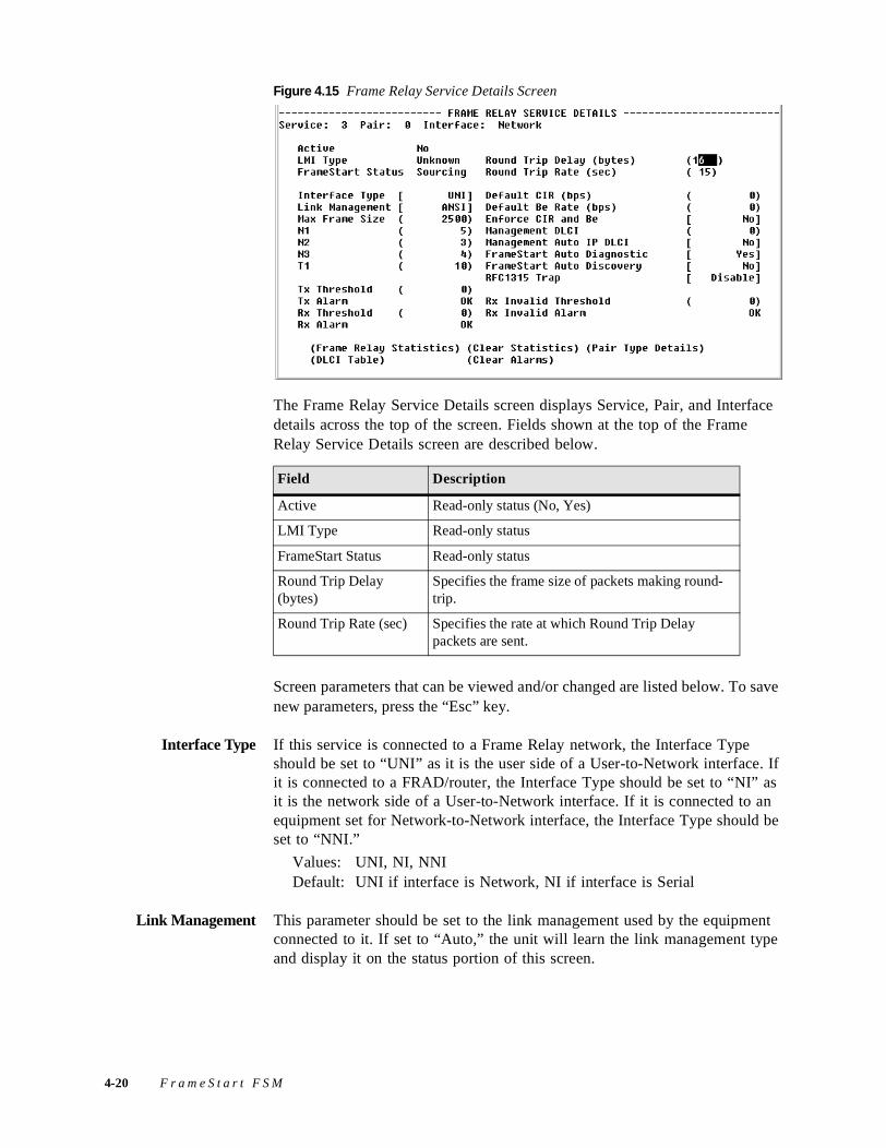
Figure 4.15 Frame Relay Service Details Screen
The Frame Relay Service Details screen displays Service, Pair, and Interface details across the top of the screen. Fields shown at the top of the Frame Relay Service Details screen are described below.
Screen parameters that can be viewed and/or changed are listed below. To save new parameters, press the “Esc” key.
Interface Type If this service is connected to a Frame Relay network, the Interface Type should be set to “UNI” as it is the user side of a User-to-Network interface. If it is connected to a FRAD/router, the Interface Type should be set to “NI” as it is the network side of a User-to-Network interface. If it is connected to an equipment set for Network-to-Network interface, the Interface Type should be set to “NNI.”
Values: UNI, NI, NNIDefault: UNI if interface is Network, NI if interface is Serial
Link Management This parameter should be set to the link management used by the equipment connected to it. If set to “Auto,” the unit will learn the link management type and display it on the status portion of this screen.
Field Description
Active Read-only status (No, Yes)
LMI Type Read-only status
FrameStart Status Read-only status
Round Trip Delay (bytes)
Specifies the frame size of packets making round-trip.
Round Trip Rate (sec) Specifies the rate at which Round Trip Delay packets are sent.
4-20 F r a m e S t a r t F S M
Once it discovers the link management type, the unit should be set to the discovered value so that subsequent unit or network re-initialization will be faster.
Values: Auto, CCITT, ANSI, LMI, NoneDefault: ANSI
Max Frame Size If Auto Diagnostic is set to “Yes,” the unit will discard received frames that are larger than the maximum frame size. If Auto Diagnostic is set to “No,” these large received frames will be sent, but will be counted in the Rx Invalid statistics.
Values: 64–4096Default: 2500
N1 Indicates the number of “keep alive” status inquiries that are sent between full status requests.
Values: 5–255Default: 5 if interface is Network (UNI), 6 if interface is Serial (NI).
N2 Specifies the total number of link reliability and protocol errors that can occur during the sliding event monitor count defined by N3. If this count is exceeded, the port is declared inactive.
Values: 1–255Default: 3
N3 Represents a Monitored Events Count. For a network, a monitored event is the receipt of a status inquiry message or the expiration of the polling verification timer T2. For a FRAD, a monitored event is the transmission of a status inquiry message. This parameter defines the size of the sliding window used by the unit to determine whether a channel or user device is active.
Values: 5–255Default: 4
T1 Specifies the number of seconds the unit waits between issuing status enquiry messages.
Values: 5–30Default: 10
Default CIR (bps) The Committed Information Rate (in bits per second) provided by your frame relay service provider. The unit will apply this value to each DLCI learned from the network side to gather statistics and to perform CIR enforcement, if required. If a DLCI is configured with a CIR different from the default, the DLCI configuration will be used instead.
Values: 0–1536000 Default: 0
Default Be Rate (bps) The Excess Burst Rate (in bits per second) provided by your frame relay service provider. The unit will apply this value to each DLCI learned from the network side to gather statistics and to perform CIR enforcement, if required.
V T 1 0 0 I n t e r f a c e 4-21
If a DLCI is configured with an Excess Burst different from the default, the DLCI configuration will be used instead.
Values: 0–1536000Default: 0
Enforce CIR and Be If this parameter is set to “Yes,” the unit will enforce Committed Information Rate and Excess Burst.
Values: No, YesDefault: No
NOTICE: The Auto Diagnostic parameter must be set to “Yes” to enforce CIR and Be.
Management DLCI If this parameter is set to “0,” the unit will look for management traffic on any DLCI. If set to a number associated with a specific DLCI, the unit will look for management traffic on that DLCI only.
Management Auto IPDLCI
If this parameter is set to “Yes,” the unit will monitor the specified DLCI for 5 pings over 5 seconds, after which the unit uses the destination address as its management IP address.
FrameStart AutoDiagnostic
When this parameter is set to “Yes,” the unit will always source LMI on both sides of the frame relay connection. The unit will dynamically learn the type of link management used on each side of the connection (Network and Serial).
When set to “No,” the unit will forward each LMI message to its service pair. If one side of the pair goes down, the other side will stop receiving LMI.
FrameStart Auto Diagnostic mode should be left set to “Yes” unless the frame relay connection has more that 128 DLCIs, or if there is a very high traffic rate on a constant basis.
Values: No, YesDefault: Yes
FrameStart AutoDiscovery
When this parameter is set to “Yes,” the unit will send FrameStart discovery and delay frames to each DLCI it learns as soon as the DLCIs are set active. This is required to calculate round-trip delay as well as to discover remote FrameStart FSM units. This parameter should be set to “Yes” only on network services that have an FSM at the far end of the frame relay connection.
Values: No, YesDefault: No
RFC1315 Trap When this parameter is set to “Enable,” the unit will send the standard RFC1315 frame relay DTE circuit state change trap every time a DLCI
4-22 F r a m e S t a r t F S M
changes state, provided at least one destination IP address for trap is configured in the SNMP configuration.
Values: Disable, EnableDefault: Disable
Tx Threshold Number of bits per second sent during a 15-minute interval after which a Tx alarm will be triggered. A value of “0” (zero) disables this trap.
Values: 0–4294967295Default: 0
Tx Alarm Status of this alarm (OK, Alarmed).
Rx Threshold Number of bits per second sent during a 15-minute interval after which an Rx alarm will be triggered. A value of “0” (zero) disables this trap.
Values: 0–4294967295Default: 0
Rx Alarm Status of this alarm (OK, Alarmed).
Rx Invalid Threshold Number of invalid frames received during a 15-minute interval after which an Rx invalid alarm will be triggered. A value of “0” (zero) disables this trap.
Values: 0–4294967295Default: 0
Rx Invalid Alarm Status of this alarm (OK, Alarmed).
User prompts at the bottom of the Frame Relay Services Details screen are described in the following table.
Select the “Frame Relay Statistics” prompt to bring up a table that reports on the status and condition of LMI parameters and on Receive/Transmit alarms and thresholds. Alarm threshold levels may be changed by entering a new threshold value in the appropriate field on the Frame Relay Service Details screen and pressing the “Esc” key.
Prompt Function
Frame Relay Statistics
Opens the Frame Relay Statistics screen for the current frame relay service.
DLCI Table Opens the DLCI Table screen, which displays all the DLCIs on the current service. Refer to DLCI Table Screen on page 4-37 for more information.
Clear Statistics Clears all Frame Relay statistics.
Clear Alarms Clears all Frame Relay alarms.
Pair Type Details Opens another Frame Relay Service Details screen that reverses the service and the pair so that you can view both sides of the pair.
V T 1 0 0 I n t e r f a c e 4-23
Figure 4.16 Frame Relay Statistics Screen
To view the Port Statistics (Figure 4.17) for a specific interval, select that interval from the Frame Relay Statistics <Period> column.
Figure 4.17 Frame Relay Port Statistics Screen
PPP Service Details ScreenThe PPP Service Details screen (Figure 4.18) gives you access to configuration parameters that can be viewed/changed as described in the following paragraphs. To save new parameters, press the “Esc” key.
4-24 F r a m e S t a r t F S M
Figure 4.18 PPP Service Details Screen
ACCM The Asynchronous Control Character Map (ACCM) configuration option provides a method to negotiate the use of control character transparency on asynchronous links.
Values: 0–4294967295Default: 4294967295
MRU The Maximum Receive Units (MRU) configuration option may be set to inform the peer that the implementation can receive larger packets, or to request that the peer send smaller packets.
Values: 128–4096Default: 1500
Port IP Address The IP Address of the Supervisory port. Set your Internet Browser to this IP address to access the Web Server interface using the Supervisory port.
Default: 192.168.1.2
Peer IP Address Enter the IP address of the peer that will negotiate authentication protocols.
Default: 192.168.1.3
Virtual PPP Over Endpoint name over which to send PPP encapsulated data (i.e., PPP over Frame Relay). Valid only when the PPP interface is Virtual.
Auth ChallengeInterval
The time interval (in seconds) between CHAP challenges. A value of “0” (zero) disables the periodic authentication challenge.
Values: 0−3600Default: 0 (disabled)
Allow PAP This parameter lets the peer negotiate for PAP.
Values: No, YesDefault: No
V T 1 0 0 I n t e r f a c e 4-25
Allow CHAP This parameter lets the peer negotiate for CHAP.
Values: No, YesDefault: No
PAP Username Type the appropriate PAP Username in this field to log on to the peer.
Values: (user established)Default: Username
PAP Password Enter the password necessary to log on to the peer under a given PAP Username.
Values: (user established)Default: (none)
CHAP Username Type the appropriate CHAP Hostname in this field to challenge the peer.
Values: (user established)Default: Hostname
CHAP Secret Enter the Secret (i.e., password) necessary to challenge the peer.
Values: (user established)Default: Secret
Initiate Negotiation Determines whether the port actively negotiates with the peer site or passively waits for negotiation requests.
Values: Yes, NoDefault: Yes
Parameters to NegotiateThe table displayed near the bottom of the PPP Service Details screen shows which parameters are set to be negotiated. You can specify which parameters should be negotiated by selecting the desired option. The table below describes the parameters that can be negotiated.
Parameter Description
Protocol Header Compression
Compresses PPP protocol headers.Default = Yes
IPCP Compression Compresses TCP headers using Van Jacobsen compression. Default = Yes
MRU Informs the peer that the implementation can receive larger packets, or requests that the peer send smaller packets.Default = Yes
HDLC Address Compression
Negotiates the compression of high-level data link control (HDLC) addresses.Default = Yes
IP Address Dynamically negotiates for IP addresses; otherwise, it is assumed both sides know each other’s IP addresses.Default = Yes
4-26 F r a m e S t a r t F S M
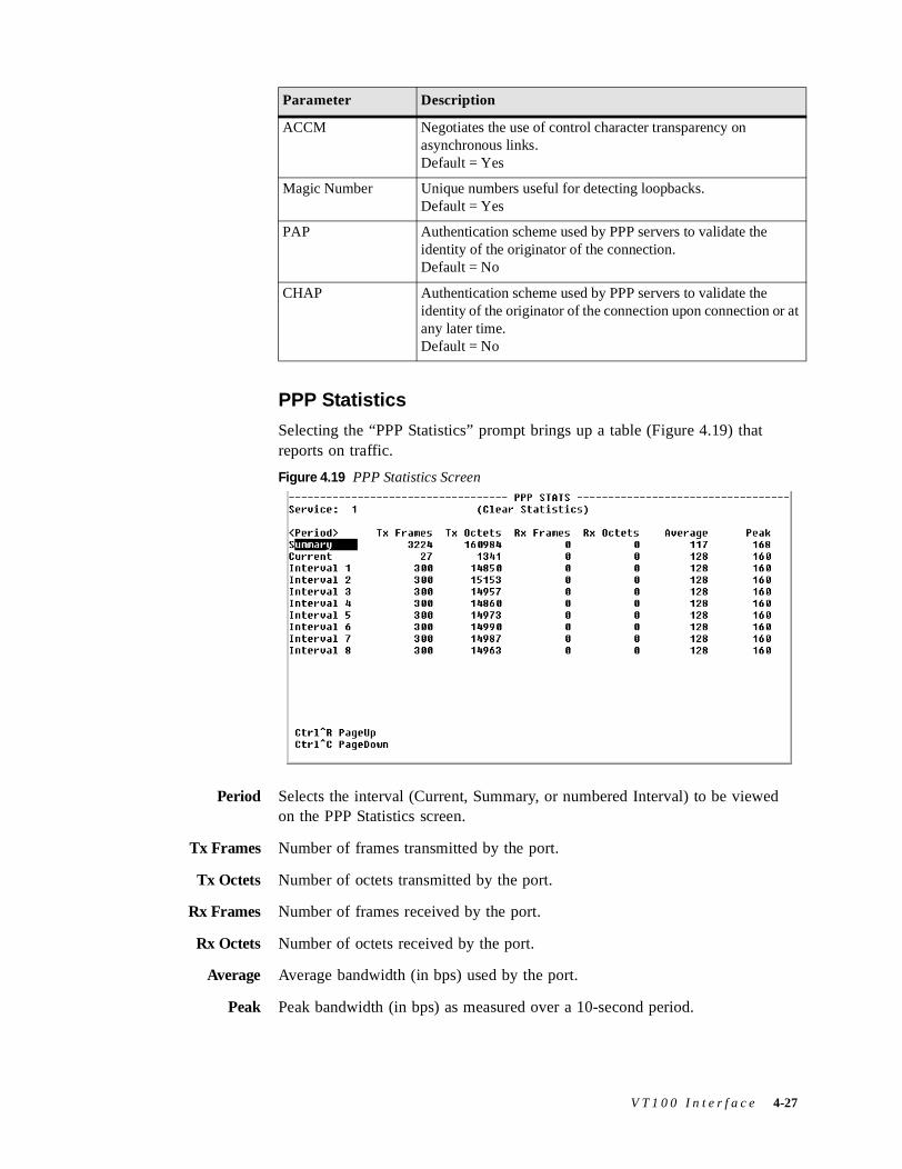
PPP Statistics
Selecting the “PPP Statistics” prompt brings up a table (Figure 4.19) that reports on traffic.
Figure 4.19 PPP Statistics Screen
Period Selects the interval (Current, Summary, or numbered Interval) to be viewed on the PPP Statistics screen.
Tx Frames Number of frames transmitted by the port.
Tx Octets Number of octets transmitted by the port.
Rx Frames Number of frames received by the port.
Rx Octets Number of octets received by the port.
Average Average bandwidth (in bps) used by the port.
Peak Peak bandwidth (in bps) as measured over a 10-second period.
ACCM Negotiates the use of control character transparency on asynchronous links. Default = Yes
Magic Number Unique numbers useful for detecting loopbacks.Default = Yes
PAP Authentication scheme used by PPP servers to validate the identity of the originator of the connection. Default = No
CHAP Authentication scheme used by PPP servers to validate the identity of the originator of the connection upon connection or at any later time.Default = No
Parameter Description
V T 1 0 0 I n t e r f a c e 4-27
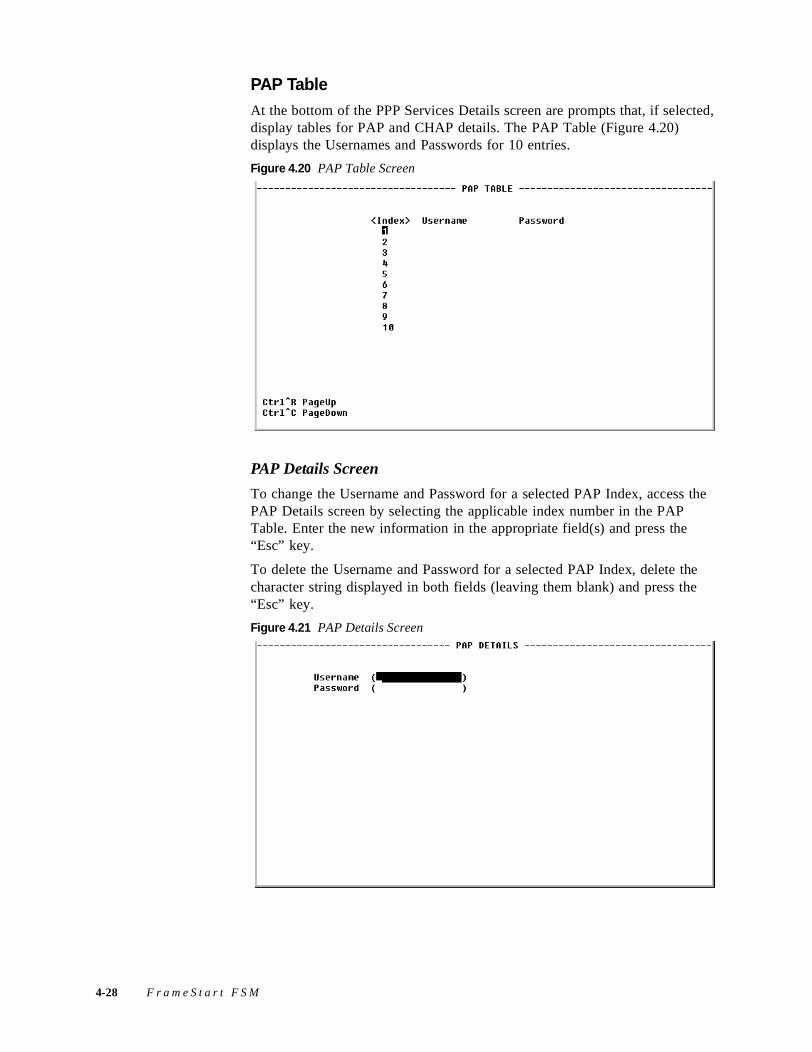
PAP TableAt the bottom of the PPP Services Details screen are prompts that, if selected, display tables for PAP and CHAP details. The PAP Table (Figure 4.20) displays the Usernames and Passwords for 10 entries.
Figure 4.20 PAP Table Screen
PAP Details Screen
To change the Username and Password for a selected PAP Index, access the PAP Details screen by selecting the applicable index number in the PAP Table. Enter the new information in the appropriate field(s) and press the “Esc” key.
To delete the Username and Password for a selected PAP Index, delete the character string displayed in both fields (leaving them blank) and press the “Esc” key.
Figure 4.21 PAP Details Screen
4-28 F r a m e S t a r t F S M
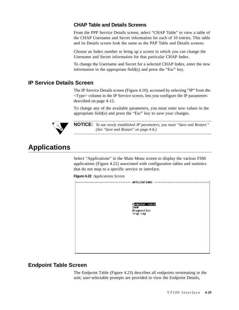
CHAP Table and Details ScreensFrom the PPP Service Details screen, select “CHAP Table” to view a table of the CHAP Username and Secret information for each of 10 entries. This table and its Details screen look the same as the PAP Table and Details screens.
Choose an Index number to bring up a screen in which you can change the Username and Secret information for that particular CHAP Index.
To change the Username and Secret for a selected CHAP Index, enter the new information in the appropriate field(s) and press the “Esc” key.
IP Service Details ScreenThe IP Service Details screen (Figure 4.10), accessed by selecting “IP” from the <Type> column in the IP Service screen, lets you configure the IP parameters described on page 4-15.
To change any of the available parameters, you must enter new values in the appropriate field(s) and press the “Esc” key to save your changes.
NOTICE: To use newly established IP parameters, you must “Save and Restart.” (See "Save and Restart" on page 4-6.)
ApplicationsSelect “Applications” in the Main Menu screen to display the various FSM applications (Figure 4.22) associated with configuration tables and statistics that do not map to a specific service or interface.
Figure 4.22 Applications Screen
Endpoint Table ScreenThe Endpoint Table (Figure 4.23) describes all endpoints terminating in the unit; user-selectable prompts are provided to view the Endpoint Details,
V T 1 0 0 I n t e r f a c e 4-29
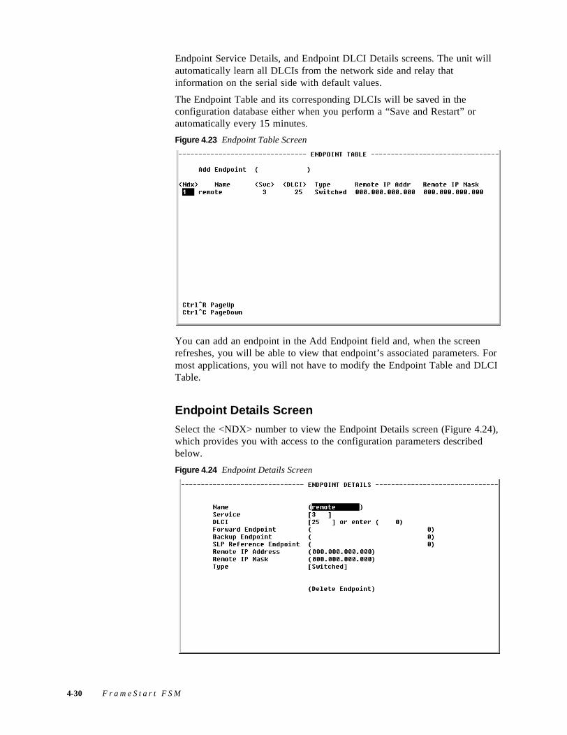
Endpoint Service Details, and Endpoint DLCI Details screens. The unit will automatically learn all DLCIs from the network side and relay that information on the serial side with default values.
The Endpoint Table and its corresponding DLCIs will be saved in the configuration database either when you perform a “Save and Restart” or automatically every 15 minutes.
Figure 4.23 Endpoint Table Screen
You can add an endpoint in the Add Endpoint field and, when the screen refreshes, you will be able to view that endpoint’s associated parameters. For most applications, you will not have to modify the Endpoint Table and DLCI Table.
Endpoint Details Screen
Select the <NDX> number to view the Endpoint Details screen (Figure 4.24), which provides you with access to the configuration parameters described below.
Figure 4.24 Endpoint Details Screen
4-30 F r a m e S t a r t F S M
Name When the unit learns a new DLCI, it creates an endpoint entry and a DLCI entry if they are not already configured. The endpoint’s Name will automatically be assigned as “Dynamic”; however, this name can (and most likely should) be changed to reflect a remote location name. Submitting a changed Name parameter will cause the endpoint entry and its corresponding DLCI entry to be saved in the configuration database.
Value: A string of up to 11 characters Default: None
CAUTION: When configuring endpoints, the name you assign each endpoint in the Name parameter field must be unique within the unit.
Service This is the Service Index number (from the Service Table) on which this DLCI was found or configured.
Values: Displays the currently active Services (by index number) or the Service(s) on which the DLCI was discovered.
Default: 0
DLCI This is the DLCI number.
Values: 16–1023Default: 0
Forward Endpoint By default, each DLCI is switched to its pair service in the Service Table using the same DLCI number. If this endpoint has to be switched to a different DLCI or a different service, the endpoint index of the destination must be configured here.
For most applications, you will not need to set this parameter.
Values: 0–256Default: 0
Backup Endpoint If this DLCI has an alternative endpoint to switch to in case this DLCI becomes inactive, you would configure the endpoint index of this alternate endpoint here.
For most applications, you will not need to set this parameter.
Values: 0–256Default: 0
SLP ReferenceEndpoint
Use this reference endpoint index for the SLA parameters. As most applications have the same SLAs for all DLCIs, they only need to be configured in one DLCI entry. You can then copy all SLA parameters from the endpoint index of this configured DLCI. If no SLP reference endpoint is configured and the DLCI SLA parameters are not configured, the values in the Frame Relay Service Details will be used (default CIR, Be, enforcement).
For most applications, you will not need to set this parameter.
Values: 0–256Default: 0
V T 1 0 0 I n t e r f a c e 4-31
Remote IP Address If this FrameStart FSM unit is to be used to manage a remote FSM unit, you must configure the IP address of the remote FSM unit here. This DLCI can be used for management only, or for management and actual data.
If this parameter is set, a PC connected to the LAN interface of this FrameStart FSM can reach a remote FSM through this DLCI. The remote IP address must be part of an IP network that is different from the local FSM, and the local FSM's IP address must be configured into the PC. This way, local and remote FSMs can be reached regardless of the availability of the routers connected at the back of the FSMs.
Values: IP addressDefault: 0.0.0.0
Remote IP Mask If the Remote IP Address is set, the Remote IP Mask must also be set.
Values: IP addressDefault: 0.0.0.0
Type If data received from this DLCI has to be switched to its corresponding destination port, you must set the type to “Switched.” Set the type to “Local” if this DLCI will be used for management purposes only.
Values: Switched, LocalDefault: Switched
Delete Endpoint You may delete any endpoint.
Endpoint Service Details Screen
Selecting from the <Svc> column on the Endpoint Table screen displays the typical Service Details screen (page 4-18) in which you can view, and in some cases change, parameters including Index, Interface, Type, and Pair. A “Delete Service” prompt is also included on this screen.
DLCI Details Screen
The DLCI Details screen (Figure 4.25) lets you access the configuration parameters described in the following paragraphs. To bring up this screen, select any DLCI from the <DLCI> column on the Endpoint Table screen.
4-32 F r a m e S t a r t F S M
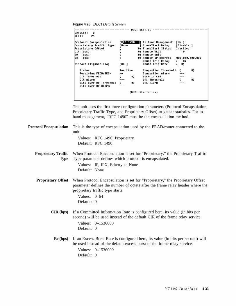
Figure 4.25 DLCI Details Screen
The unit uses the first three configuration parameters (Protocol Encapsulation, Proprietary Traffic Type, and Proprietary Offset) to gather statistics. For in-band management, “RFC 1490” must be the encapsulation method.
Protocol Encapsulation This is the type of encapsulation used by the FRAD/router connected to the unit.
Values: RFC 1490, ProprietaryDefault: RFC 1490
Proprietary TrafficType
When Protocol Encapsulation is set for “Proprietary,” the Proprietary Traffic Type parameter defines which protocol is encapsulated.
Values: IP, IPX, Ethertype, NoneDefault: None
Proprietary Offset When Protocol Encapsulation is set for “Proprietary,” the Proprietary Offset parameter defines the number of octets after the frame relay header where the proprietary traffic type starts.
Values: 0–64Default: 0
CIR (bps) If a Committed Information Rate is configured here, its value (in bits per second) will be used instead of the default CIR of the frame relay service.
Values: 0–1536000Default: 0
Be (bps) If an Excess Burst Rate is configured here, its value (in bits per second) will be used instead of the default excess burst of the frame relay service.
Values: 0–1536000Default: 0
V T 1 0 0 I n t e r f a c e 4-33

Bc (bps) If CIR enforcement is configured to “Yes,” the unit will throttle the Committed Burst down to this value (in bits per second) when frames are received with the BECN bit set.
Values: 0–1536000Default: 0
Discard Eligible Flag If this parameter is set to “Yes,” and CIR enforcement is also set to “Yes,” the unit will set the Discard Eligible (DE) bit for frames sent over CIR.
Values: Yes, NoDefault: No
In Band Management If the unit is to be used as a gateway to reach a remote FrameStart FSM through this DLCI, set this parameter to “Yes,” and configure the remote IP address and Mask in the corresponding endpoint.
Values: Yes, NoDefault: No
FrameStart Delay If this parameter is set to “Enable,” the unit will send FrameStart discovery and delay frames on this DLCI, and will report the state of the remote Verilink FSx unit. It will also send SOS frames when the FRAD/router connected to this unit goes inactive.
Values: Enable, DisableDefault: Enable if Auto Discovery is set to “Yes”; otherwise Disable
FrameStart Status If the remote unit is a Verilink FSx product and FrameStart Auto Discovery is enabled, the FrameStart Status field will show the status of the remote unit. The status is “Active” if both the local and remote DLCIs are active and the remote unit answers to the discovery frames sent by this unit. The status is “SOS” if the remote unit is active but the FRAD/router connected to it is inactive. The status is “Inactive” in all other cases.
Values: Active, Inactive, SOSDefault: Inactive
Remote DLCI If the remote unit is a Verilink FSx product, and FrameStart Auto Discovery is enabled, this field displays the DLCI number used on the remote end of this DLCI.
Values: 16−1023Default: 0
Remote Unit If the remote unit is a Verilink FSx product, and FrameStart Auto Discovery is enabled, this field displays the first three digits of the unit ID configured on the remote end of this DLCI.
Values: 000−999Default: 000
Round Trip Delay Specifies the frame size (in bytes) of packets making round-trip.
Round Trip Rate Specifies the rate (in seconds) at which Round Trip Delay packets are sent.
4-34 F r a m e S t a r t F S M
DLCI Status Table
The bottom portion of the screen shows a table detailing the actual status of this DLCI and alarm threshold information as follows:
Status If this DLCI is up, the status will be “Active”; otherwise, the status will be “Inactive.”
Values: Active, InactiveDefault: Inactive
Receiving FECN/BECN
When a frame is received with congestion bit set, this parameter is set to “Yes.” It is set back to “No” when a frame is received without congestion bit set.
Values: Yes, NoDefault: No
CIR Threshold Sets the Tx over CIR alarm threshold. This threshold is the number of bits per second in excess of CIR during a 15-minute interval. Setting this field to “0” (zero) disables the alarm.
CIR Alarm Reports if the Tx over CIR threshold has been exceeded.
Bits Over Be Threshold Sets the Tx over the excess burst (Be) alarm threshold. This threshold is the number of bits per second in excess of CIR + Be during a 15-minute interval. Setting this field to “0” (zero) disables the alarm.
Bits Over Be Alarm Reports if the Tx over Be threshold has been exceeded.
Congestion Threshold Sets the Rx Congestion alarm threshold. This threshold is the number of frames received with BECN/FECN. Setting this field to “0” (zero) disables the alarm.
Congestion Alarm Reports if the Rx Congestion threshold has been exceeded.
BECN in CIR Reports if Backward Explicit Congestion Notification (BECN) has been received within CIR.
UAS Threshold Sets the Unavailable Seconds (UAS) alarm threshold. This threshold is the number of seconds after which the DLCI is unavailable. Setting this field to “0” (zero) disables the alarm.
UAS Alarm Reports if the UAS threshold has been exceeded.
DLCI Statistics Screen
Selecting “DLCI Statistics” on the Endpoint DLCI Details screen will display the screen below.
V T 1 0 0 I n t e r f a c e 4-35
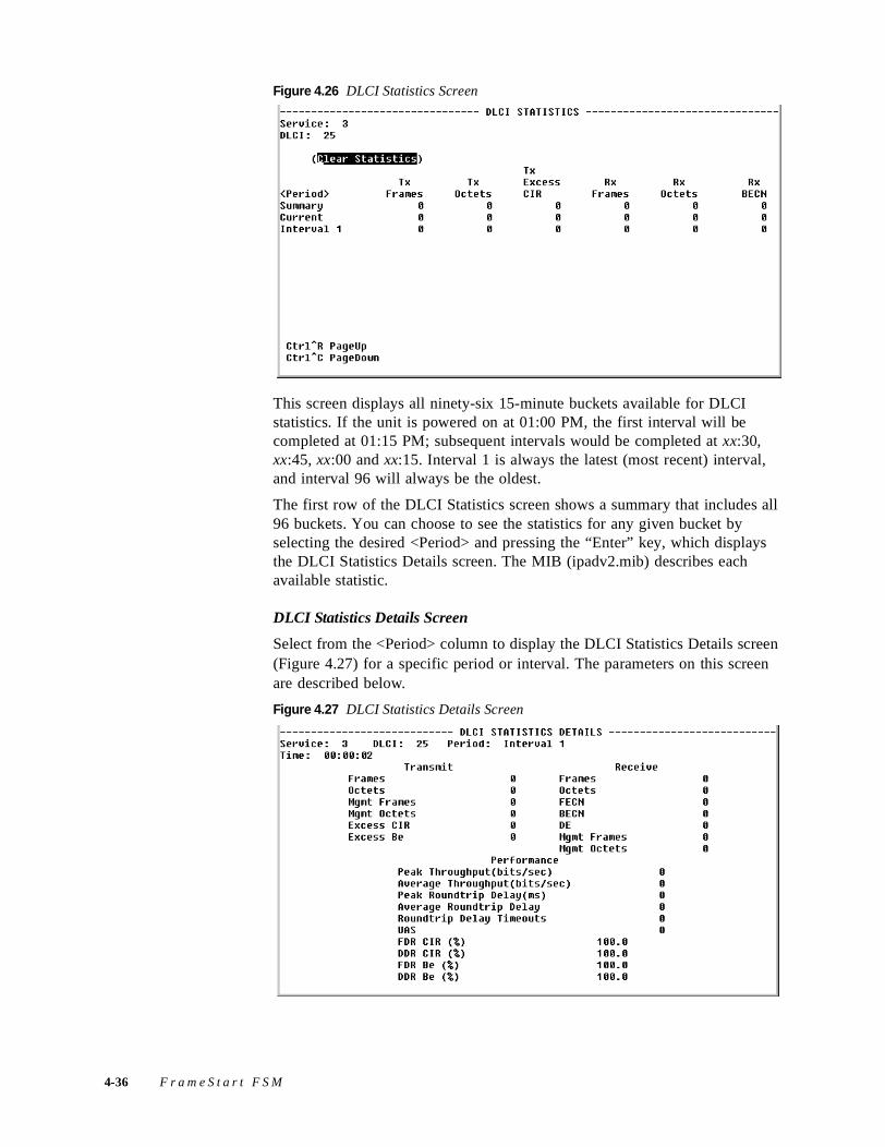
Figure 4.26 DLCI Statistics Screen
This screen displays all ninety-six 15-minute buckets available for DLCI statistics. If the unit is powered on at 01:00 PM, the first interval will be completed at 01:15 PM; subsequent intervals would be completed at xx:30, xx:45, xx:00 and xx:15. Interval 1 is always the latest (most recent) interval, and interval 96 will always be the oldest.
The first row of the DLCI Statistics screen shows a summary that includes all 96 buckets. You can choose to see the statistics for any given bucket by selecting the desired <Period> and pressing the “Enter” key, which displays the DLCI Statistics Details screen. The MIB (ipadv2.mib) describes each available statistic.
DLCI Statistics Details Screen
Select from the <Period> column to display the DLCI Statistics Details screen (Figure 4.27) for a specific period or interval. The parameters on this screen are described below.
Figure 4.27 DLCI Statistics Details Screen
4-36 F r a m e S t a r t F S M
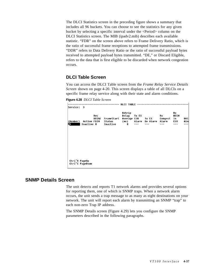
The DLCI Statistics screen in the preceding figure shows a summary that includes all 96 buckets. You can choose to see the statistics for any given bucket by selecting a specific interval under the <Period> column on the DLCI Statistics screen. The MIB (ipadv2.mib) describes each available statistic. “FDR” on the screen above refers to Frame Delivery Ratio, which is the ratio of successful frame receptions to attempted frame transmissions. “DDR” refers to Data Delivery Ratio or the ratio of successful payload bytes received to attempted payload bytes transmitted. “DE,” or Discard Eligible, refers to the data that is first eligible to be discarded when network congestion occurs.
DLCI Table Screen
You can access the DLCI Table screen from the Frame Relay Service Details Screen shown on page 4-20. This screen displays a table of all DLCIs on a specific frame relay service along with their state and alarm conditions.
Figure 4.28 DLCI Table Screen
SNMP Details ScreenThe unit detects and reports T1 network alarms and provides several options for reporting them, one of which is SNMP traps. When a network alarm occurs, the unit sends a trap message to as many as eight destinations on your network. The unit will report each alarm by transmitting an SNMP “trap” to each non-zero Trap IP address.
The SNMP Details screen (Figure 4.29) lets you configure the SNMP parameters described in the following paragraphs.
V T 1 0 0 I n t e r f a c e 4-37
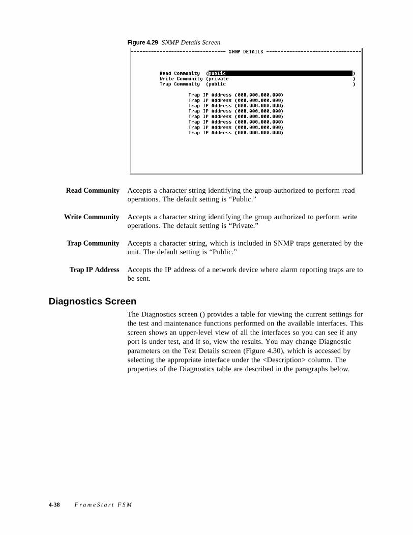
Figure 4.29 SNMP Details Screen
Read Community Accepts a character string identifying the group authorized to perform read operations. The default setting is “Public.”
Write Community Accepts a character string identifying the group authorized to perform write operations. The default setting is “Private.”
Trap Community Accepts a character string, which is included in SNMP traps generated by the unit. The default setting is “Public.”
Trap IP Address Accepts the IP address of a network device where alarm reporting traps are to be sent.
Diagnostics ScreenThe Diagnostics screen () provides a table for viewing the current settings for the test and maintenance functions performed on the available interfaces. This screen shows an upper-level view of all the interfaces so you can see if any port is under test, and if so, view the results. You may change Diagnostic parameters on the Test Details screen (Figure 4.30), which is accessed by selecting the appropriate interface under the <Description> column. The properties of the Diagnostics table are described in the paragraphs below.
4-38 F r a m e S t a r t F S M
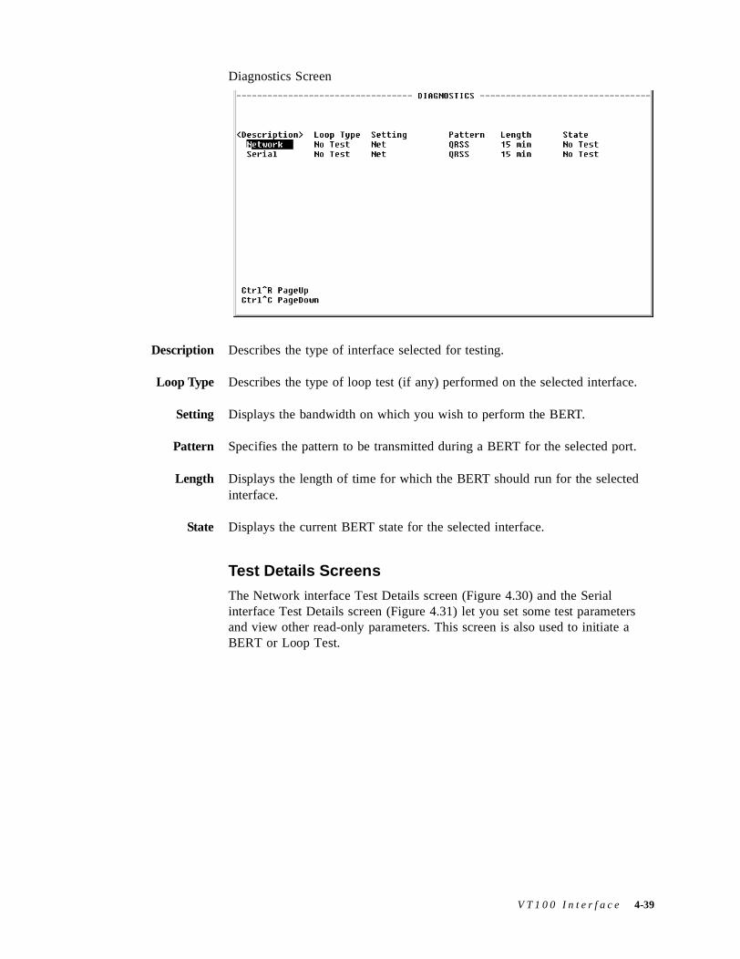
Diagnostics Screen
Description Describes the type of interface selected for testing.
Loop Type Describes the type of loop test (if any) performed on the selected interface.
Setting Displays the bandwidth on which you wish to perform the BERT.
Pattern Specifies the pattern to be transmitted during a BERT for the selected port.
Length Displays the length of time for which the BERT should run for the selected interface.
State Displays the current BERT state for the selected interface.
Test Details Screens
The Network interface Test Details screen (Figure 4.30) and the Serial interface Test Details screen (Figure 4.31) let you set some test parameters and view other read-only parameters. This screen is also used to initiate a BERT or Loop Test.
V T 1 0 0 I n t e r f a c e 4-39
Figure 4.30 Network Test Details Screen
BERT Table on Network Interface Test Details Screen
The BERT table provided on the Test Details screen lets you set the test parameters listed below.
Setting Displays the bandwidth on which you wish to perform the BERT. The available values for this parameter depend on which interface is selected.
Values: Net, Use Service, Idle, Channel 1...24, Default: Net
BERT Pattern Specifies the pattern to be transmitted during a test for the selected port.
Values: Marks, QRSS, 511, 2047, 215, SpacesDefault: QRSS
NOTICE: The 215 pattern is the ITU (European) version, not the ANSI version.
Test Duration Specifies the length of time for which the test should run for the selected port.
Values: 15 minutes, 30 minutes, 1 hour, 24 hours, ContinuousDefault: 15 minutes
From this screen, you can also view the following read-only parameters:
Service Index Selects the channels with a service to BERT. (Refer to the Service Table Screen shown on page 4-17.)
Rate Sets the bit rate to BERT for each selected channel. If “Νx64K” is selected, the ones density requirements of the T1 network line must be ensured. If “Νx56K” is selected, ones density for the selected DS0 channel is maintained.
Values: Nx56K, Nx64KDefault: Nx64K
4-40 F r a m e S t a r t F S M
Pattern Sync Displays the state of pattern sync during a test. If no test is in progress, “No Test” is displayed. If a test is active, but the receiver is not in pattern sync, “No Sync” is displayed. If the receiver is in pattern sync, “In Sync” is displayed.
Elapsed Time Displays the time elapsed since a timed test began or, if completed, the total test time.
Bit Errors Displays the total number of bit errors detected since the test began or since error statistics were cleared.
Errored Seconds Displays the number of asynchronous errored seconds that have been detected since the test began or since error statistics were last cleared.
%EFS Displays the percentage of time that the test ran error-free. This ratio is derived from the number of error-free seconds divided by the number of seconds accumulated in Elapsed Time
Loop Table on the Network Interface Test Details Screen
The Loop table lets you specify the type of Loop test to be performed.
Values: No Test (Loop Down), line loopback (LLB), maintenance loopback (MLB), Far PLB, Far LLB
Default: No Test (Loop Down)
Figure 4.31 Serial Interface Test Details Screen
BERT Table on the Serial Interface Test Details Screen
The BERT table lets you set the test parameters listed below.
Setting Displays the bandwidth on which you wish to perform the BERT. The available values for this parameter depend on which interface is selected.
Values: Net, DTEDefault: Net
V T 1 0 0 I n t e r f a c e 4-41
BERT Pattern Specifies the pattern to be transmitted during a test for the selected port.
Values: Marks, QRSS, 511, 2047, 215, SpacesDefault: QRSS
NOTICE: The 215 pattern is the ITU (European) version, not the ANSI version.
Test Duration Specifies the length of time for which the test should run for the selected port.
Values: 15 minutes, 30 minutes, 1 hour, 24 hours, ContinuousDefault: 15 minutes
You can also view the following read-only parameters from this screen:
Pattern Sync Displays the state of pattern sync during a test. If no test is in progress, “No Test” is displayed. If a test is active, but the receiver is not in pattern sync, “No Sync” is displayed. If the receiver is in pattern sync, “In Sync” is displayed.
Elapsed Time Displays the time elapsed since a timed test began or, if completed, the total test time.
Bit Errors Displays the total number of bit errors detected since the test began or since error statistics were cleared.
Errored Seconds Displays the number of asynchronous errored seconds that have been detected since the test began or since error statistics were last cleared.
%EFS Displays the percentage of time that the test ran error-free. This ratio is derived from the number of error-free seconds divided by the number of seconds accumulated in Elapsed Time.
Loop Table on the Serial Interface Test Details Screen
The Loop table lets you specify the type of Loop test to be performed. The types of tests available for you to choose from depend on the currently selected interface.
Values: No Test (Loop Down), Port Loop, V.54 Loop, Far V.54 LoopDefault: No Test (Loop Down)
The Test Details screens provide the following user-selectable prompts:
Prompt Function
Start BERT Starts the specified BERT.
Stop BERT Stops the currently running BERT.
Error Inject Injects a bit error.
Reset Errors Resets the current error count.
4-42 F r a m e S t a r t F S M
Trap Log ScreenThe Trap Log screen (Figure 4.32) shows a collection of all the traps that have been generated. A trap is a mechanism that permits a device to send an alarm for certain network events to an SNMP management station.
The table shown in this screen lists each trap by its Index number, and displays the type of error captured by the trap (Trap Number) and the date and time that the trap was stored (Time Stamp).
Figure 4.32 Trap Log Screen
V T 1 0 0 I n t e r f a c e 4-43

4-44 F r a m e S t a r t F S M

C H A P T E R
5CHAPTER 5FRONT PANEL LCD INTERFACE
IntroductionThis chapter describes the menus and options associated with the FrameStart FSM’s front panel LCD interface.
Description of Front Panel
The front panel of the FrameStart FSM unit has four LED status indicators, three user-activated input control buttons, and a 2-line, 16-character LCD screen that provides access to unit configuration, diagnostics, and utilities.
Figure 5.1 Verilink FrameStart FSM Front Panel
F r o n t P a n e l L C D I n t e r f a c e 5-1
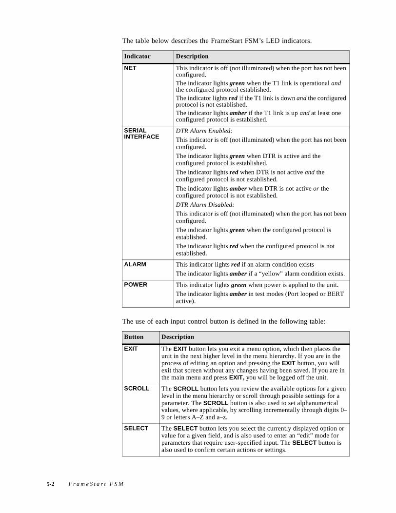
The table below describes the FrameStart FSM’s LED indicators.
The use of each input control button is defined in the following table:
Indicator Description
NET This indicator is off (not illuminated) when the port has not been configured. The indicator lights green when the T1 link is operational and the configured protocol established.The indicator lights red if the T1 link is down and the configured protocol is not established. The indicator lights amber if the T1 link is up and at least one configured protocol is established.
SERIAL INTERFACE
DTR Alarm Enabled:
This indicator is off (not illuminated) when the port has not been configured.
The indicator lights green when DTR is active and the configured protocol is established.
The indicator lights red when DTR is not active and the configured protocol is not established.
The indicator lights amber when DTR is not active or the configured protocol is not established.
DTR Alarm Disabled:
This indicator is off (not illuminated) when the port has not been configured.
The indicator lights green when the configured protocol is established.
The indicator lights red when the configured protocol is not established.
ALARM This indicator lights red if an alarm condition exists
The indicator lights amber if a “yellow” alarm condition exists.
POWER This indicator lights green when power is applied to the unit.
The indicator lights amber in test modes (Port looped or BERT active).
Button Description
EXIT The EXIT button lets you exit a menu option, which then places the unit in the next higher level in the menu hierarchy. If you are in the process of editing an option and pressing the EXIT button, you will exit that screen without any changes having been saved. If you are in the main menu and press EXIT, you will be logged off the unit.
SCROLL The SCROLL button lets you review the available options for a given level in the menu hierarchy or scroll through possible settings for a parameter. The SCROLL button is also used to set alphanumerical values, where applicable, by scrolling incrementally through digits 0–9 or letters A–Z and a–z.
SELECT The SELECT button lets you select the currently displayed option or value for a given field, and is also used to enter an “edit” mode for parameters that require user-specified input. The SELECT button is also used to confirm certain actions or settings.
5-2 F r a m e S t a r t F S M
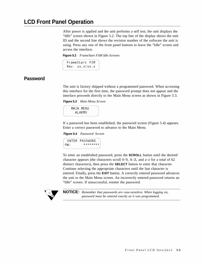
LCD Front Panel OperationAfter power is applied and the unit performs a self test, the unit displays the “Idle” screen shown in Figure 5.2. The top line of the display shows the unit ID and the second line shows the revision number of the software the unit is using. Press any one of the front panel buttons to leave the “Idle” screen and access the interface.
Password
The unit is factory shipped without a programmed password. When accessing this interface for the first time, the password prompt does not appear and the interface proceeds directly to the Main Menu screen as shown in Figure 5.3.
If a password has been established, the password screen (Figure 5.4) appears. Enter a correct password to advance to the Main Menu.
To enter an established password, press the SCROLL button until the desired character appears (the characters scroll 0–9, A–Z, and a–z for a total of 62 distinct characters), then press the SELECT button to enter that character. Continue selecting the appropriate characters until the last character is entered. Finally, press the EXIT button. A correctly entered password advances the unit to the Main Menu screen. An incorrectly entered password returns an “Idle” screen. If unsuccessful, reenter the password.
NOTICE: Remember that passwords are case-sensitive. When logging on, password must be entered exactly as it was programmed.
FrameStart FSM Rev. xx.x/xx.x
Figure 5.2 FrameStart FSM Idle Screens
MAIN MENUALARMS
Figure 5.3 Main Menu Screen
ENTER PASSWORD PW: ********
Figure 5.4 Password Screen
F r o n t P a n e l L C D I n t e r f a c e 5-3
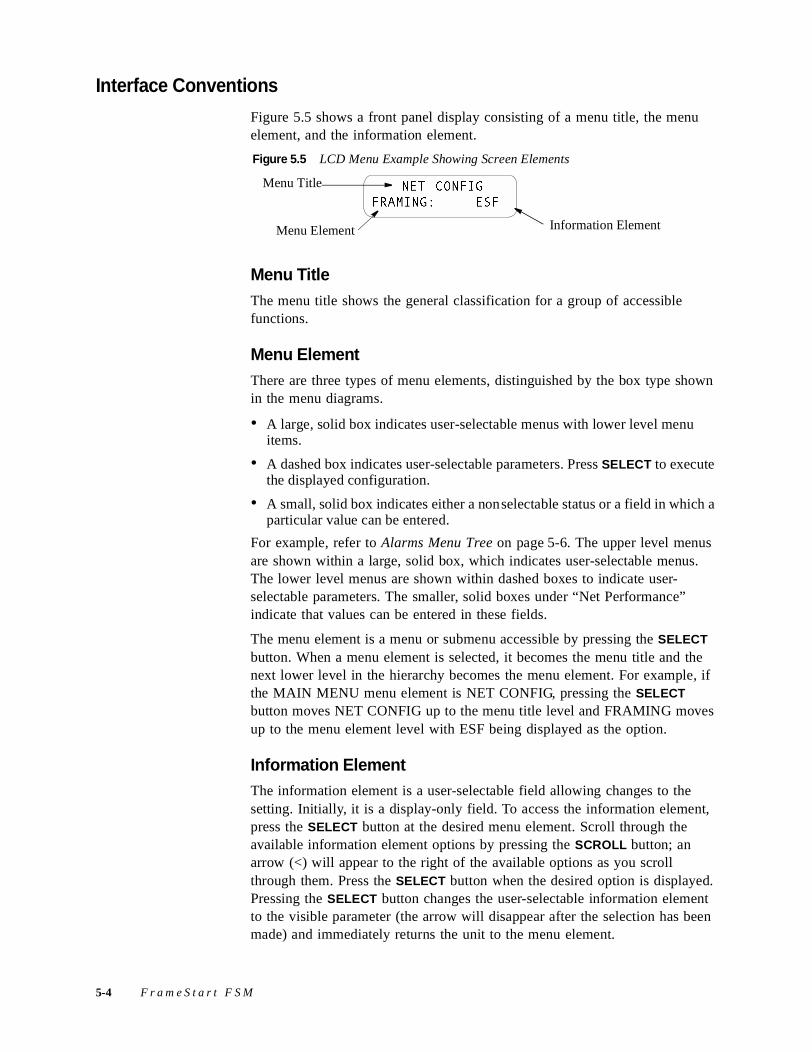
Interface Conventions
Figure 5.5 shows a front panel display consisting of a menu title, the menu element, and the information element.
Menu TitleThe menu title shows the general classification for a group of accessible functions.
Menu ElementThere are three types of menu elements, distinguished by the box type shown in the menu diagrams.
• A large, solid box indicates user-selectable menus with lower level menu items.
• A dashed box indicates user-selectable parameters. Press SELECT to execute the displayed configuration.
• A small, solid box indicates either a nonselectable status or a field in which a particular value can be entered.
For example, refer to Alarms Menu Tree on page 5-6. The upper level menus are shown within a large, solid box, which indicates user-selectable menus. The lower level menus are shown within dashed boxes to indicate user-selectable parameters. The smaller, solid boxes under “Net Performance” indicate that values can be entered in these fields.
The menu element is a menu or submenu accessible by pressing the SELECT button. When a menu element is selected, it becomes the menu title and the next lower level in the hierarchy becomes the menu element. For example, if the MAIN MENU menu element is NET CONFIG, pressing the SELECT button moves NET CONFIG up to the menu title level and FRAMING moves up to the menu element level with ESF being displayed as the option.
Information ElementThe information element is a user-selectable field allowing changes to the setting. Initially, it is a display-only field. To access the information element, press the SELECT button at the desired menu element. Scroll through the available information element options by pressing the SCROLL button; an arrow (<) will appear to the right of the available options as you scroll through them. Press the SELECT button when the desired option is displayed. Pressing the SELECT button changes the user-selectable information element to the visible parameter (the arrow will disappear after the selection has been made) and immediately returns the unit to the menu element.
Menu Element
NET CONFIGFRAMING: ESF
Menu Title
Information Element
Figure 5.5 LCD Menu Example Showing Screen Elements
5-4 F r a m e S t a r t F S M
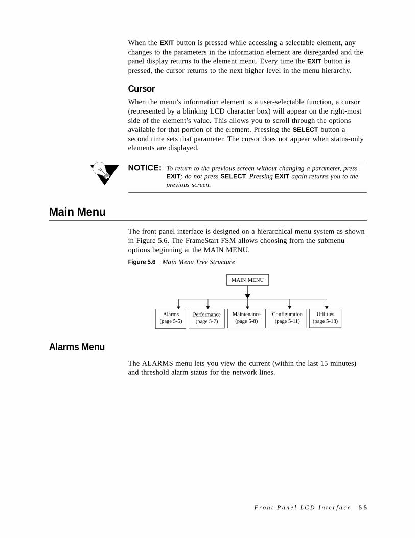
When the EXIT button is pressed while accessing a selectable element, any changes to the parameters in the information element are disregarded and the panel display returns to the element menu. Every time the EXIT button is pressed, the cursor returns to the next higher level in the menu hierarchy.
CursorWhen the menu’s information element is a user-selectable function, a cursor (represented by a blinking LCD character box) will appear on the right-most side of the element’s value. This allows you to scroll through the options available for that portion of the element. Pressing the SELECT button a second time sets that parameter. The cursor does not appear when status-only elements are displayed.
NOTICE: To return to the previous screen without changing a parameter, press EXIT; do not press SELECT. Pressing EXIT again returns you to the previous screen.
Main MenuThe front panel interface is designed on a hierarchical menu system as shown in Figure 5.6. The FrameStart FSM allows choosing from the submenu options beginning at the MAIN MENU.
Figure 5.6 Main Menu Tree Structure
Alarms Menu
The ALARMS menu lets you view the current (within the last 15 minutes) and threshold alarm status for the network lines.
Alarms(page 5-5)
MAIN MENU
Maintenance(page 5-8)
Utilities(page 5-18)
Performance(page 5-7)
Configuration(page 5-11)
F r o n t P a n e l L C D I n t e r f a c e 5-5
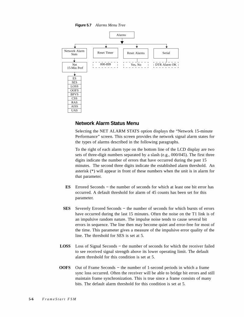
Figure 5.7 Alarms Menu Tree
Network Alarm Status MenuSelecting the NET ALARM STATS option displays the “Network 15-minute Performance” screen. This screen provides the network signal alarm states for the types of alarms described in the following paragraphs.
To the right of each alarm type on the bottom line of the LCD display are two sets of three-digit numbers separated by a slash (e.g., 000/045). The first three digits indicate the number of errors that have occurred during the past 15 minutes. The second three digits indicate the established alarm threshold. An asterisk (*) will appear in front of these numbers when the unit is in alarm for that parameter.
ES Errored Seconds − the number of seconds for which at least one bit error has occurred. A default threshold for alarm of 45 counts has been set for this parameter.
SES Severely Errored Seconds − the number of seconds for which bursts of errors have occurred during the last 15 minutes. Often the noise on the T1 link is of an impulsive random nature. The impulse noise tends to cause several bit errors in sequence. The line then may become quiet and error-free for most of the time. This parameter gives a measure of the impulsive error quality of the line. The threshold for SES is set at 5.
LOSS Loss of Signal Seconds − the number of seconds for which the receiver failed to see received signal strength above its lower operating limit. The default alarm threshold for this condition is set at 5.
OOFS Out of Frame Seconds − the number of 1-second periods in which a frame sync loss occurred. Often the receiver will be able to bridge bit errors and still maintain frame synchronization. This is true since a frame consists of many bits. The default alarm threshold for this condition is set at 5.
Network Alarm Stats
Alarms
SerialReset Alarms
Net 15-Min Perf
ESSES
LOSSOOFSBPVSCSSRASAISSUAS
DTR Alarm OKYes, No
Reset Timer
000-899
5-6 F r a m e S t a r t F S M
BPVS Bipolar Violation Seconds − the number of times the signal failed to observe the rules for changing the polarity of the logic “1” transmitted signal. The default alarm threshold for this condition is set at 0. This means that this alarm is initially turned off.
CSS Controlled Slip Seconds − indicates the number of seconds during which a timing correction was needed due to buffer under-run or overflow. The default alarm threshold for this condition is set at 5.
RAS Remote Alarm Seconds − the number of seconds the RAI/yellow alarm has been reported from the remote end of the T1 link. The default alarm threshold for this condition is set at 0. This means that this alarm is initially turned off.
AISS Alarm Indication Signal Seconds -- the number of seconds AIS has been received. The default alarm threshold for this condition is set at 0; this means that this alarm is initially turned off.
UAS Unavailable Seconds -- the number of seconds for which data was not available at the T1 port. The default alarm threshold for this condition is set at 0. This means that this alarm is initially off.
NOTICE: Alarm detection and generation are per the guidelines set forth in ANSI T1M1.3. Other relevant standards include ANSI T1.403-1989 and AT&T PUB 54016
DTR Alarm Read-only field that displays the current DTR Alarm status. This register shows “OK” when no alarms are detected, and shows “ALRMD” when the unit alarms a loss of DTR.
Reset Timer This field is the contiguous number of seconds that an alarm parameter must be clear before the alarm is reset. Applicable values range from 000 through 899. A value of “000” means that the alarm never resets. Press SELECT to change this threshold.
Reset Alarms This option clears the alarm counts. To reset the alarms, press the SCROLL button to bring up the “Yes” option, and then press the SELECT button.
Performance Menu
The PERFORMANCE menu displays a history of the network error parameters that are continuously monitored. This register lets you view the 24-hour performance totals from the unit.
F r o n t P a n e l L C D I n t e r f a c e 5-7
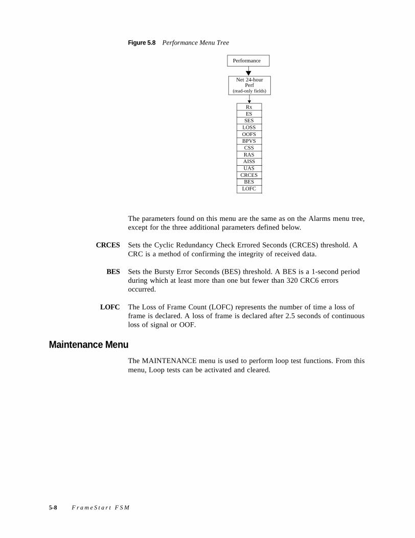
Figure 5.8 Performance Menu Tree
The parameters found on this menu are the same as on the Alarms menu tree, except for the three additional parameters defined below.
CRCES Sets the Cyclic Redundancy Check Errored Seconds (CRCES) threshold. A CRC is a method of confirming the integrity of received data.
BES Sets the Bursty Error Seconds (BES) threshold. A BES is a 1-second period during which at least more than one but fewer than 320 CRC6 errors occurred.
LOFC The Loss of Frame Count (LOFC) represents the number of time a loss of frame is declared. A loss of frame is declared after 2.5 seconds of continuous loss of signal or OOF.
Maintenance Menu
The MAINTENANCE menu is used to perform loop test functions. From this menu, Loop tests can be activated and cleared.
Net 24-hourPerf
(read-only fields)
Performance
RxES
SESLOSSOOFSBPVSCSSRASAISSUAS
CRCESBES
LOFC
5-8 F r a m e S t a r t F S M
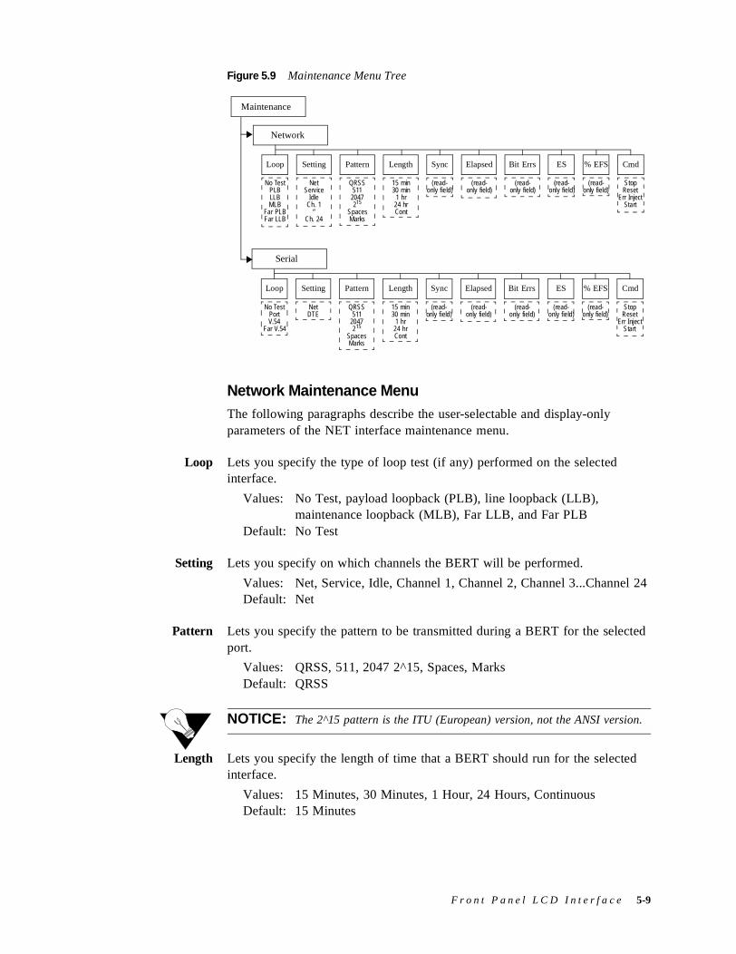
Figure 5.9 Maintenance Menu Tree
Network Maintenance MenuThe following paragraphs describe the user-selectable and display-only parameters of the NET interface maintenance menu.
Loop Lets you specify the type of loop test (if any) performed on the selected interface.
Values: No Test, payload loopback (PLB), line loopback (LLB), maintenance loopback (MLB), Far LLB, and Far PLB
Default: No Test
Setting Lets you specify on which channels the BERT will be performed.
Values: Net, Service, Idle, Channel 1, Channel 2, Channel 3...Channel 24 Default: Net
Pattern Lets you specify the pattern to be transmitted during a BERT for the selected port.
Values: QRSS, 511, 2047 2^15, Spaces, MarksDefault: QRSS
NOTICE: The 2^15 pattern is the ITU (European) version, not the ANSI version.
Length Lets you specify the length of time that a BERT should run for the selected interface.
Values: 15 Minutes, 30 Minutes, 1 Hour, 24 Hours, ContinuousDefault: 15 Minutes
Maintenance
Network
Serial
Loop Setting Pattern Length Sync Elapsed Bit Errs ES % EFS Cmd
No TestPLBLLBMLB
Far PLBFar LLB
NetService
IdleCh. 1
“Ch. 24
QRSS511
2047215
SpacesMarks
15 min30 min
1 hr24 hrCont
(read- only field)
(read- only field)
(read- only field)
(read- only field)
(read- only field)
StopReset
Err InjectStart
Loop Setting Pattern Length Sync Elapsed Bit Errs ES % EFS Cmd
No TestPortV.54
Far V.54
NetDTE
QRSS511
2047215
SpacesMarks
15 min30 min
1 hr24 hrCont
(read- only field)
(read- only field)
(read- only field)
(read- only field)
(read- only field)
StopReset
Err InjectStart
F r o n t P a n e l L C D I n t e r f a c e 5-9
Sync Display-only field shows the state of pattern sync during a BERT. If no BERT is in progress, “No Test” is displayed. If a BERT is active, but the receiver is not in pattern sync, “No Sync” is displayed. If the receiver is in pattern sync, “In Sync” is displayed.
Elapsed Display-only field shows the amount of time (in seconds) that has elapsed since a BERT began or, if completed, the total test time.
Bit Errors Display-only field shows the number of bit errors detected since the BERT began or since error statistics were last cleared.
ES Display-only field shows the number of asynchronous errored seconds that have been detected since the BERT began or since error statistics were last cleared. This parameter includes bit error seconds and sync loss seconds.
% EFS Display-only field shows what percent of the total test time ran error free. This ratio is derived from the number of error free seconds divided by the number of seconds accumulated in Elapsed Time.
Cmd Lets you control basic aspects of the BERT performed, including the injection of errors during test.
Values: Stop, Reset, Error Inject, StartDefault: Stop
Serial Maintenance MenuThe following paragraphs describe the user-selectable and display-only parameters of the SERIAL interface maintenance menu.
Loop Lets you specify the type of loop test (if any) performed on the selected serial interface.
Values: No Test, Port, V.54, Far.V.54Default: No Test
Setting Lets you specify the direction towards which the BERT pattern is sent.
Values: Net, DTE Default: Net
Pattern Lets you specify the pattern to be transmitted during a BERT for the selected port.
Values: QRSS, 511, 2047, 2^15, Spaces, MarksDefault: QRSS
NOTICE: The 2^15 pattern is the ITU (European) version, not the ANSI version.
5-10 F r a m e S t a r t F S M
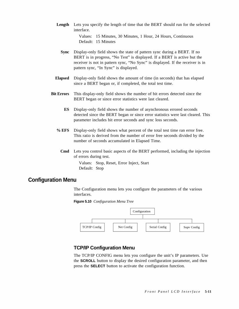
Length Lets you specify the length of time that the BERT should run for the selected interface.
Values: 15 Minutes, 30 Minutes, 1 Hour, 24 Hours, ContinuousDefault: 15 Minutes
Sync Display-only field shows the state of pattern sync during a BERT. If no BERT is in progress, “No Test” is displayed. If a BERT is active but the receiver is not in pattern sync, “No Sync” is displayed. If the receiver is in pattern sync, “In Sync” is displayed.
Elapsed Display-only field shows the amount of time (in seconds) that has elapsed since a BERT began or, if completed, the total test time.
Bit Errors This display-only field shows the number of bit errors detected since the BERT began or since error statistics were last cleared.
ES Display-only field shows the number of asynchronous errored seconds detected since the BERT began or since error statistics were last cleared. This parameter includes bit error seconds and sync loss seconds.
% EFS Display-only field shows what percent of the total test time ran error free. This ratio is derived from the number of error free seconds divided by the number of seconds accumulated in Elapsed Time.
Cmd Lets you control basic aspects of the BERT performed, including the injection of errors during test.
Values: Stop, Reset, Error Inject, StartDefault: Stop
Configuration Menu
The Configuration menu lets you configure the parameters of the various interfaces.
Figure 5.10 Configuration Menu Tree
TCP/IP Configuration MenuThe TCP/IP CONFIG menu lets you configure the unit’s IP parameters. Use the SCROLL button to display the desired configuration parameter, and then press the SELECT button to activate the configuration function.
Configuration
Serial ConfigNet ConfigTCP/IP Config Supv Config
F r o n t P a n e l L C D I n t e r f a c e 5-11
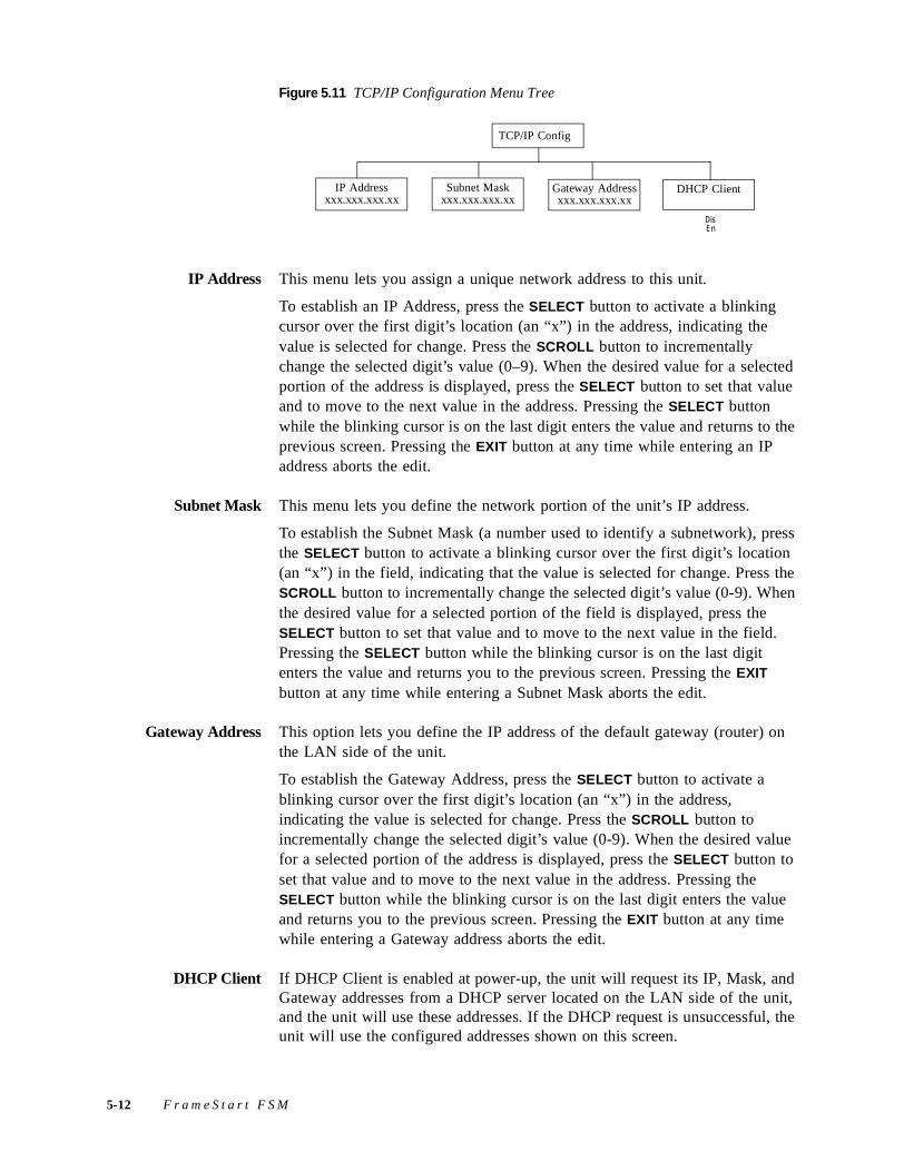
Figure 5.11 TCP/IP Configuration Menu Tree
IP Address This menu lets you assign a unique network address to this unit.
To establish an IP Address, press the SELECT button to activate a blinking cursor over the first digit’s location (an “x”) in the address, indicating the value is selected for change. Press the SCROLL button to incrementally change the selected digit’s value (0–9). When the desired value for a selected portion of the address is displayed, press the SELECT button to set that value and to move to the next value in the address. Pressing the SELECT button while the blinking cursor is on the last digit enters the value and returns to the previous screen. Pressing the EXIT button at any time while entering an IP address aborts the edit.
Subnet Mask This menu lets you define the network portion of the unit’s IP address.
To establish the Subnet Mask (a number used to identify a subnetwork), press the SELECT button to activate a blinking cursor over the first digit’s location (an “x”) in the field, indicating that the value is selected for change. Press the SCROLL button to incrementally change the selected digit’s value (0-9). When the desired value for a selected portion of the field is displayed, press the SELECT button to set that value and to move to the next value in the field. Pressing the SELECT button while the blinking cursor is on the last digit enters the value and returns you to the previous screen. Pressing the EXIT button at any time while entering a Subnet Mask aborts the edit.
Gateway Address This option lets you define the IP address of the default gateway (router) on the LAN side of the unit.
To establish the Gateway Address, press the SELECT button to activate a blinking cursor over the first digit’s location (an “x”) in the address, indicating the value is selected for change. Press the SCROLL button to incrementally change the selected digit’s value (0-9). When the desired value for a selected portion of the address is displayed, press the SELECT button to set that value and to move to the next value in the address. Pressing the SELECT button while the blinking cursor is on the last digit enters the value and returns you to the previous screen. Pressing the EXIT button at any time while entering a Gateway address aborts the edit.
DHCP Client If DHCP Client is enabled at power-up, the unit will request its IP, Mask, and Gateway addresses from a DHCP server located on the LAN side of the unit, and the unit will use these addresses. If the DHCP request is unsuccessful, the unit will use the configured addresses shown on this screen.
TCP/IP Config
Subnet Maskxxx.xxx.xxx.xx
IP Addressxxx.xxx.xxx.xx
Gateway Addressxxx.xxx.xxx.xx
DHCP Client
DisEn
5-12 F r a m e S t a r t F S M
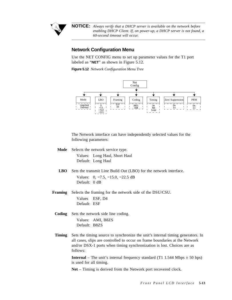
NOTICE: Always verify that a DHCP server is available on the network before enabling DHCP Client. If, on power-up, a DHCP server is not found, a 60-second timeout will occur.
Network Configuration MenuUse the NET CONFIG menu to set up parameter values for the T1 port labeled as “NET” as shown in Figure 5.12.
Figure 5.12 Network Configuration Menu Tree
The Network interface can have independently selected values for the following parameters:
Mode Selects the network service type.
Values: Long Haul, Short HaulDefault: Long Haul
LBO Sets the transmit Line Build Out (LBO) for the network interface.
Values: 0, −7.5, −15.0, −22.5 dBDefault: 0 dB
Framing Selects the framing for the network side of the DSU/CSU.
Values ESF, D4Default: ESF
Coding Sets the network side line coding.
Values: AMI, B8ZSDefault: B8ZS
Timing Sets the timing source to synchronize the unit’s internal timing generators. In all cases, slips are controlled to occur on frame boundaries at the Network and/or DSX-1 ports when timing synchronization is lost. Choices are as follows:
Internal – The unit’s internal frequency standard (T1 1.544 Mbps ± 50 bps) is used for all timing.
Net – Timing is derived from the Network port recovered clock.
NetConfig
Framing Coding TimingLBO
ESFD4 B8ZS
AMIIntNet
Serial
0−7.5−15.0−22.5
Zero Suppression
DisEn
PRM
DisEn
Mode
Long-HaulShrt-Haul
F r o n t P a n e l L C D I n t e r f a c e 5-13
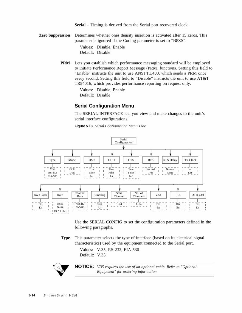
Serial – Timing is derived from the Serial port recovered clock.
Zero Suppression Determines whether ones density insertion is activated after 15 zeros. This parameter is ignored if the Coding parameter is set to “B8ZS”.
Values: Disable, EnableDefault: Disable
PRM Lets you establish which performance messaging standard will be employed to initiate Performance Report Message (PRM) functions. Setting this field to “Enable” instructs the unit to use ANSI T1.403, which sends a PRM once every second. Setting this field to “Disable” instructs the unit to use AT&T TR54016, which provides performance reporting on request only.
Values: Disable, EnableDefault: Disable
Serial Configuration MenuThe SERIAL INTERFACE lets you view and make changes to the unit’s serial interface configurations.
Figure 5.13 Serial Configuration Menu Tree
Use the SERIAL CONFIG to set the configuration parameters defined in the following paragraphs.
Type This parameter selects the type of interface (based on its electrical signal characteristics) used by the equipment connected to the Serial port.
Values: V.35, RS-232, EIA-530Default: V.35
NOTICE: V.35 requires the use of an optional cable. Refer to "Optional Equipment" for ordering information.
V.35RS-232EIA-530
Type Mode DSR DCD CTS RTS RTS Delay Tx Clock
DCEDTE
TrueFalseInt
TrueFalse
Int
TrueFalseIn*
NormalTrue
NormalLong
IntExt
Nx56Nx64
(N = 1–32)
Channel RateRateInv Clock Bundling
Start Channel
No. of Channels V.54 LL DTR Ctrl
Nx64KNx56K
ContAlt
1–24 1–24 DisEn
DisEn
DisEn
DisEn
SerialConfiguration
5-14 F r a m e S t a r t F S M
Mode By default, the Serial port serves as a DCE port in both Packet and TDM modes. However, the Serial port can serve as a DTE port when the unit is in Packet mode.
If the Serial port connects to a DTE device (such as a FRAD or a router), the Mode parameter must be set to “DCE.” If this port connects to a DCE device (such as a DSU/CSU), this parameter must be set to “DTE” (valid only for Packet mode, not TDM).
Values: DCE, DTEDefault: DCE
NOTICE: DTE mode requires the use of an optional DTE cable. Refer to Appendix A,"Specifications," for ordering information.
DSR Data Set Ready can be set to “True,” “False,” or “Internal.” The “Internal” option sets DSR “On” if the port is enabled and “Off” if the port is disabled.
Values: True, False, InternalDefault: True
DCD The Data Carrier Detect parameter can be set to “True,” “False,” or “Internal.” If set to “Internal,” DCD is “On” when network carrier is being received from the remote end, and is “Off” when network carrier is not being received from the far end.
Values: True, False, InternalDefault: True
CTS The Clear To Send parameter can be set to “True” or “False.” If this parameter is set to “Internal,” the CTS control lead follows the RTS control lead from the DTE after a delay of a duration established by the RTS Delay parameter.
Values: True, False, InternalDefault: True
RTS The Request To Send parameter determines where the unit reads the RTS signal status from. If set to “Normal,” the unit gets RTS from the Serial pin. If set to “True,” RTS is always perceived as “On.”
Values: Normal, TrueDefault: Normal
RTS Delay The RTS Delay parameter determines how long the unit waits before it changes the level of CTS to match RTS when the CTS parameter is set to “Internal.”
Values: Normal (~30 ms delay), Long (~100 ms delay)Default: Normal
F r o n t P a n e l L C D I n t e r f a c e 5-15
Tx Clock Used to select the clock that the unit uses to sample the data transmitted from the DTE. When set to “Internal,” the data is sampled directly with the transmit data clock that is also supplied to the DTE as Transmit Clock.
Values: Internal, ExternalDefault: Internal
Inv Clock For use in DTE Packet mode to change the clock edge of the transmitted data.
Values: Enable, DisableDefault: Disable
Rate If the port is running in Packet mode, the Rate must be configured to the desired port speed. In TDM mode, the port speed rate will be set by configuring the next four parameters (Start Channel, Number of Channels, Bundling, and Channel Rate). The menu displays the calculated rate in kilobits per second.
Values: Nx56K, Nx64K, where N = 1−32Default: 1536 kbps
Channel Rate The unit can operate at any data rate that is a multiple of 56 or 64 kbps. If “Νx64K” is selected, the ones density requirements of the T1 network line must be ensured. If “Νx56K” is selected, ones density for the selected DS0 channel is maintained. The menu displays the calculated rate in kilobits per second.
Values: Nx56K, Nx64KDefault: Nx64K
Bundling Selects whether the DTE channel assignment is made as a “Contiguous” group or as “Alternate” channels. Selecting “Alternate” ensures ones density. Because the unit allows individual channels to be configured for a service, a value of “Arbitrary” will be returned for this parameter if the current channel allocation is not contiguous or Alternate. The “Arbitrary” value can only be supplied by the unit − it cannot be set by the user.
Values: Contiguous, AlternateDefault: Contiguous
NOTICE: Because the “Alternate” Bundling option works by stuffing even channels with ones (1’s) and using odd channels for data, the available bandwidth is actually half of that selected.
Start Channel Selects the starting channel in the 24-channel DS1 bit stream. Starting with the specified channel, the unit automatically assigns the channels that follow.
Values: 1 through 24Default: 1
5-16 F r a m e S t a r t F S M
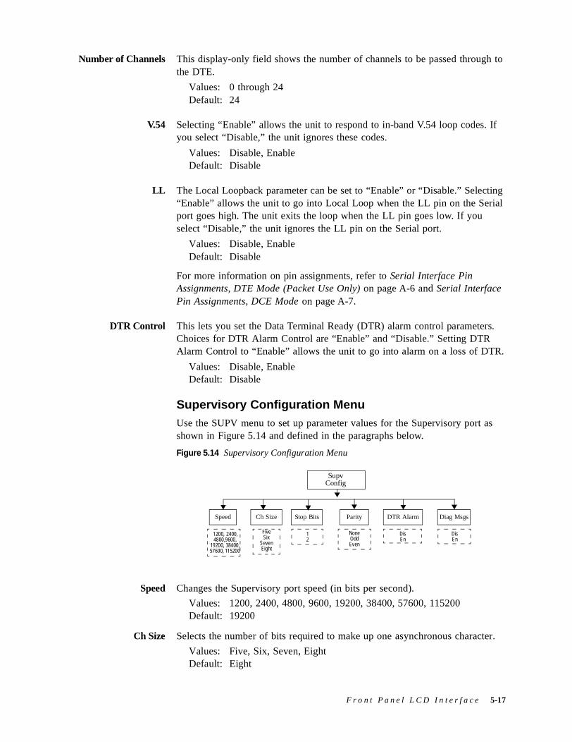
Number of Channels This display-only field shows the number of channels to be passed through to the DTE.
Values: 0 through 24Default: 24
V.54 Selecting “Enable” allows the unit to respond to in-band V.54 loop codes. If you select “Disable,” the unit ignores these codes.
Values: Disable, EnableDefault: Disable
LL The Local Loopback parameter can be set to “Enable” or “Disable.” Selecting “Enable” allows the unit to go into Local Loop when the LL pin on the Serial port goes high. The unit exits the loop when the LL pin goes low. If you select “Disable,” the unit ignores the LL pin on the Serial port.
Values: Disable, EnableDefault: Disable
For more information on pin assignments, refer to Serial Interface Pin Assignments, DTE Mode (Packet Use Only) on page A-6 and Serial Interface Pin Assignments, DCE Mode on page A-7.
DTR Control This lets you set the Data Terminal Ready (DTR) alarm control parameters. Choices for DTR Alarm Control are “Enable” and “Disable.” Setting DTR Alarm Control to “Enable” allows the unit to go into alarm on a loss of DTR.
Values: Disable, EnableDefault: Disable
Supervisory Configuration MenuUse the SUPV menu to set up parameter values for the Supervisory port as shown in Figure 5.14 and defined in the paragraphs below.
Figure 5.14 Supervisory Configuration Menu
Speed Changes the Supervisory port speed (in bits per second).
Values: 1200, 2400, 4800, 9600, 19200, 38400, 57600, 115200Default: 19200
Ch Size Selects the number of bits required to make up one asynchronous character.
Values: Five, Six, Seven, EightDefault: Eight
SupvConfig
Speed ParityStop Bits
1200, 2400, 4800,9600,
19200, 38400, 57600, 115200
NoneOddEven
12
DTR Alarm
DisEn
Diag Msgs
DisEn
FiveSix
SevenEight
Ch Size
F r o n t P a n e l L C D I n t e r f a c e 5-17
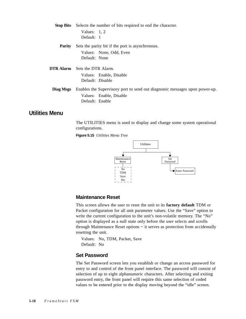
Stop Bits Selects the number of bits required to end the character.
Values: 1, 2Default: 1
Parity Sets the parity bit if the port is asynchronous.
Values: None, Odd, EvenDefault: None
DTR Alarm Sets the DTR Alarm.
Values: Enable, DisableDefault: Disable
Diag Msgs Enables the Supervisory port to send out diagnostic messages upon power-up.
Values: Enable, DisableDefault: Enable
Utilities Menu
The UTILITIES menu is used to display and change some system operational configurations.
Figure 5.15 Utilities Menu Tree
Maintenance ResetThis screen allows the user to reset the unit to its factory default TDM or Packet configuration for all unit parameter values. Use the “Save” option to write the current configuration to the unit’s non-volatile memory. The “No” option is displayed as a null state only before the user selects and scrolls through Maintenance Reset options − it serves as protection from accidentally resetting the unit.
Values: No, TDM, Packet, SaveDefault: No
Set PasswordThe Set Password screen lets you establish or change an access password for entry to and control of the front panel interface. The password will consist of selection of up to eight alphanumeric characters. After selecting and exiting password entry, the front panel will require this same selection of coded values to be entered prior to the display moving beyond the “idle” screen.
Maintenance Reset
Utilities
Set Password
NoTDMSavePkt
Enter Password
5-18 F r a m e S t a r t F S M
Select the Set Password option to open the ENTER PASSWORD screen; a blinking cursor appears over the first character or digit to be entered or modified. To establish a unit password, press the SCROLL button to increment the characters and digits (0–9, A–Z, a–z). Pressing the SELECT button accepts the value and moves the cursor to the right. After entering all the characters that define your password, press the SELECT button; the menu will then prompt you to “Verify” the password. Reenter the password exactly as before and again press SELECT. A correctly entered password advances the unit to the Main Menu screen. An incorrectly entered password returns you to an “Idle” screen. If unsuccessful, reenter the password.
To disable the password function, select the Set Password option and then, without pressing the SCROLL button, press the SELECT button until the cursor passes through all eight character spaces. The menu will then prompt you to “Verify” the password. Reenter the password exactly as before and again press SELECT.
Log Out Menu
If the unit is not programmed with a password, you can end the session with the computer and leave the menu system by pressing EXIT while in the Main Menu. If a password has been programmed, the unit prevents an inadvertent log out by requiring you to press SELECT in the Log Out menu.
F r o n t P a n e l L C D I n t e r f a c e 5-19

5-20 F r a m e S t a r t F S M
A P P E N D I X
AAPPENDIX ASPECIFICATIONS
Network InterfaceLine Rate: 1.544 Mbps (±50 ppm)
Line Framing: D4 or ESF
Line Code: AMI or B8ZS
Input Signal: DS1, +1 to −27 dB (ALBO)
Connection: RJ-48C jack, 100 Ω (±5%)
Output Signal: 3.0 V (±10%) base-peak into 100 Ω with protection
Mode: Long-haul, Short-haul
DSX-1 Level: 0-110, 111-220, 221-330, 331-440, 441-550, 551-660, >661 ft
Line Build Out: 0, −7.5, −15, −22.5 dB attenuation
Transient Voltage: 1000 V protection, fused input /output
Jitter Control: per TR 62411 and T1.403
Timing Source: Internal, Network, Serial
Ones Density: B8ZS, Nx56K bit stuffing, alternate fill; complies with TR 62411
Serial InterfaceConnection DB-25 female
DTE Ports: Selectable RS-530, RS-232, or V.35
Data Rate: Synchronous, nx56 kbps or nx64 kbps (where n = 1–32)
Clocking: Internal, External
Management Interfaces
10/100 EthernetConnection: 8-pin modular
Network Protocol: TCP/IP based networks
A-1
Data Rate: 10/100 Mbps
Compatibility: 10/100Base-T
Supervisory PortConnection: DB-9 femaleData Rates: 1200, 2400, 4800, 9600, 19200, 38400, 57600, 115200 bps
(default: 19.2 kbps)
DiagnosticsPerformance: 15-minute, 24-hr, and 30-day monitoring (sampled every
second)
Network Loops: Line loopback, payload loopback, or maintenance loopback
Fractional Loop: Generates and responds to in-band V.54 loop code
DTE Port Loops: V.54 and Local
BERT: Multiple test patterns toward network or DTE ports with error inject
AlarmsActivation: Programmable thresholds on all interfaces
Reporting: SNMP traps
Power100−240 VAC: 7 W maximum, 24 BTU maximum
MechanicalMounting: Standalone
Dimensions: Width 11.75 inches (29.845 cm)
Height 1.86 inches (4.724 cm)
Depth 8.75 inches (22.225 cm)
Weight: 2.13 pounds (0.97 kg)
EnvironmentalOperating Temp: 32 to 122 °F (0° to 50 °C)
Storage Temp: −4 to 149 °F (−20 to 65 °C)
Humidity: 95% maximum (non-condensing)
A-2 F r a m e S t a r t F S M
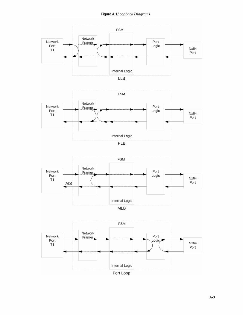
A-3
Figure A.1Loopback Diagrams
FSM
Internal Logic
NetworkPortT1
NetworkFramer Port
LogicNx64Port
LLB
FSM
Internal Logic
NetworkPortT1
NetworkFramer Port
LogicNx64Port
PLB
FSM
Internal Logic
NetworkPortT1
NetworkFramer Port
LogicNx64Port
MLB
AIS
FSM
Internal Logic
NetworkPortT1
NetworkFramer Port
LogicNx64Port
Port Loop

Frame Relay Statistics Collected in 96 15-minute IntervalsPer Port Tx/Rx frames
Tx/Rx octets
Tx/Rx Mgmt Frames
Tx/Rx Mgmt Octets
Rx frames with FECN
Rx frames with BECN
Rx invalid frames
Tx/Rx status inquiry frames
Tx/Rx status response frames
Rx invalid LMI frames
Peak/Average Throughput
Per DLCI Tx/Rx frames
Tx/Rx octets
Rx frames with FECN
Rx frames with BECN
Rx frames with DE bit set
Tx excess CIR
Tx excess Be
Tx/Rx Mgmt Frames
Tx/Rx Mgmt Octets
Peak/Average Throughput
Peak/Average Round-trip delay
Round-trip delay time-outs
UAS (unavailable seconds)
Industry ListingsFCC Compliance: Part 15 Class A, Subpart B, Part 68
U.S. Safety: UL 1950 3rd edition
Canadian Safety: CSA C22.2 No. 950-95
Industry Canada: CS-03, Issue 8 Standards
TR62411: December 1990
TR54016: September 1989
ANSI T1.403: 1995
TR54019A: April 1988
Ethernet: ISO/IEC 8802-3
Internet: RFC1907RFC1573RFC2863RFC2493
A-4 F r a m e S t a r t F S M
RFC2115RFC2495RFC2011RFC2012RFC2013RFC2096RFC2571ds8200tc.mibds8200v2.mibipadv2.mibipstart.mibrouter.mibhdsl2.mib|RFC1490
Ordering InformationEach FSM unit is supplied with the following standard equipment:
Optional EquipmentThe following optional equipment is available for use with the FSM:
Contact Verilink Technical Support (see page x) for more information.
Description
FrameStart FSM Unit
T1 Network Cable (RJ-48−RJ-48)
Power Supply
Cord for Power Supply
Serial (SUPV) Cable (DB-9 male to DB-9 female)
Verilink Documentation CD
Description
Serial (DCE) Cable (DB-25−DB25) (EIA530/RS232)
Serial (DCE) Cable (DB-25−Winchester 34-pin) (V.35), 5-foot
Serial (DCE) Cable (DB-25−Winchester 34-pin) (V.35), 10-foot
Serial (DTE) Cable (DB-25–DB25, M/M, crossed), 6-ft
Serial (DTE) Cable (DB-25–V.35, M/M, crossed), 5-ft
A-5
Connector Pin AssignmentsThe Serial Interface is a standard DB-25 jack.
Serial Interface Pin Assignments, DTE Mode (Packet Use Only)
*This refers to the DB-25 Serial interface connector on the back of the unit.
Function Abbrev. Direction
Pin #
DB-25* RS-232 V.35 EIA-530
Frame Ground FG n/a 1 1 A 1
Transmit Data TD Output 3 2 P 2
Receive Data RD Input 2 3 R 3
Request to Send RTS Output 5 4 C 4
Clear to Send CTS Input 4 5 D 5
Data Set Ready DSR Input 20 6 E 6
Signal Ground SG n/a 7 7 B 7
Data Carrier Detect DCD Input 8 8 F 8
Balanced Receiver Clock (B)RC Input 12 X 9
Balanced Data Carrier Detect (B)DCD Input 10 10
Balanced External Transmitter Clock (B)ETC
Balanced Transmitter Clock (B)TC Input 11 AA 12
Balanced Clear to Send (B)CTS Input 19 13
Balanced Transmit Data (B)TD Output 16 S 14
Transmitter Clock TC Input 24 15 Y 15
Balanced Receive Data (B)RD Input 14 T 16
Receiver Clock RC Input 15 17 V 17
Local Loopback Loop 3 Output 18 18 J 18
Balanced Request to Send (B)RTS Output 13 19
Data Terminal Ready DTR Output 6 20 H 20
(Not used) n/a 21 21 21
Balanced Data Set Ready (B)DSR Input 23 22
Balanced Data Terminal Ready (B)DTR Output 22 23
External Transmitter Clock ETC
(Not used) n/a 25 25 25
A-6 F r a m e S t a r t F S M
Serial Interface Pin Assignments, DCE Mode
*This refers to the DB-25 Serial interface connector on the back of the unit.
Function Abbrev. Direction
Pin #
DB-25* RS-232 V.35 EIA-530
Frame Ground FG n/a 1 1 A 1
Transmit Data TD Input 2 2 P 2
Receive Data RD Output 3 3 R 3
Request to Send RTS Input 4 4 C 4
Clear to Send CTS Output 5 5 D 5
Data Set Ready DSR Output 6 6 E 6
Signal Ground SG n/a 7 7 B 7
Data Carrier Detect DCD Output 8 8 F 8
Balanced Receiver Clock (B)RC Output 9 X 9
Balanced Data Carrier Detect (B)DCD Output 10 10
Balanced External Transmitter Clock (B)ETC Input 11 W 11
Balanced Transmitter Clock (B)TC Output 12 AA 12
Balanced Clear to Send (B)CTS Output 13 13
Balanced Transmit Data (B)TD Input 14 S 14
Transmitter Clock TC Output 15 15 Y 15
Balanced Receive Data (B)RD Output 16 T 16
Receiver Clock RC Output 17 17 V 17
Local Loopback Loop 3 Input 18 18 J 18
Balanced Request to Send (B)RTS Input 19 19
Data Terminal Ready DTR Input 20 20 H 20
(not used) n/a 21 21 21
Balanced Data Set Ready (B)DSR Output 22 22
Balanced Data Terminal Ready (B)DTR Input 23 23
External Transmitter Clock ETC Input 24 24 U 24
(Not Used) n/a 25 25 25
A-7
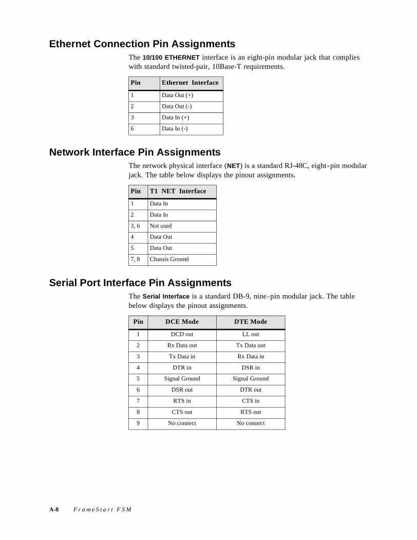
Ethernet Connection Pin AssignmentsThe 10/100 ETHERNET interface is an eight-pin modular jack that complies with standard twisted-pair, 10Base-T requirements.
Network Interface Pin AssignmentsThe network physical interface (NET) is a standard RJ-48C, eight-pin modular jack. The table below displays the pinout assignments.
Serial Port Interface Pin AssignmentsThe Serial Interface is a standard DB-9, nine-pin modular jack. The table below displays the pinout assignments.
Pin Ethernet Interface
1 Data Out (+)
2 Data Out (-)
3 Data In (+)
6 Data In (-)
Pin T1 NET Interface
1 Data In
2 Data In
3, 6 Not used
4 Data Out
5 Data Out
7, 8 Chassis Ground
Pin DCE Mode DTE Mode
1 DCD out LL out
2 Rx Data out Tx Data out
3 Tx Data in Rx Data in
4 DTR in DSR in
5 Signal Ground Signal Ground
6 DSR out DTR out
7 RTS in CTS in
8 CTS out RTS out
9 No connect No connect
A-8 F r a m e S t a r t F S M

Supervisory Port Pin Assignments
The SUPERVISORY PORT interface is a standard DB-9, 9-pin modular jack. The following table displays the pinout assignments.
Pin DCE Mode DTE Mode
1 DCD out LL out
2 Rx Data out Tx Data out
3 Tx Data in Rx Data in
4 DTR in DSR in
5 Signal Ground Signal Ground
6 DSR out DTR out
7 RTS in CTS in
8 CTS out RTS out
9 No connect No connect
A-9

A-10 F r a m e S t a r t F S M
A P P E N D I X
BAPPENDIX BSNMP AGENT
IntroductionThis chapter provides specific information for configuring and using the SNMP agent within the FSM.
The FSM incorporates an Ethernet card that provides connectivity for LAN-based management stations. The embedded TCP/IP Protocol Stack allows remote access from both private networks and the Internet.
SNMP Configuration ParametersTo access the SNMP agent, you must have an SNMP management application, such as HP’s OpenView or Sun’s NetManager. Access to the agent is controlled by three community strings: read-access, write-access, and trap-access (the community string sent with an SNMP trap). Configuration of these community strings within the FSM is accomplished via the HTTP (web browser) interface. Please refer to Chapter 3, Web Server Interface, for instructions on how this is performed.
The defaults for these strings are “public” for read-access, “private” for write-access, and “public” for trap-access. Ensure that your SNMP management application is configured for whatever access strings you use.
SNMP MIBsThe FrameStart FSM supports the following industry-standard MIB (management information base) files:
• rfc1907.mib − SNMPv2 entities (initial revision published as RFC 1450)
• rfc1573.mib − defines the IANAifType textual convention, and thus the enumerated values of the ifType object defined in MIB-II’s ifTable
B-1
• rfc2863.mib − describes generic objects for network interface sub-layers (This MIB is an updated version of MIB-II's ifTable, and incorporates the extensions defined in RFC 1229.)
• rfc2493.mib − provides textual conventions to be used by systems supporting 15-minute based performance history counts
• rfc2115.mib − describes the use of a Frame Relay interface by a DTE
• rfc2495.mib − describes DS1, E1, DS2 and E2 interfaces objects
• rfc2011.mib − for managing IP and ICMP implementations, but excluding their management of IP routes
• rfc2012.mib − for managing TCP implementations
• rfc2013.mib − for managing UDP implementations
• rfc2096.mib − for the display of CIDR multipath IP routes
• rfc2571.mib − the SNMP Management Architecture MIB
The FrameStart FSM supports the following Enterprise-specific MIBs:
• ds8200tc.mib − textual conventions used by DS8200 MIB
• ds8200v2.mib − provides T1 configuration and statistics information
• ipadv2.mib − provides Frame Relay and PPP configuration and statistics
• ipstart.mib − MIB module for synchronous PPP
These MIB files may be found on the Verilink Documentation CD included with the unit.
SNMP Trap ConfigurationThe FSM supports up to eight IP destinations for SNMP traps. These may be configured either through the Web interface or through an SNMP management application. For configuration of these destinations through an SNMP management application, use a MIB browser to access the table trapdest within ipadv2.mib and set the IP addresses of the host computer running the management application(s). Entering an IP address of 0.0.0.0 will disable the entry.
Generic MIB Loading InstructionsThe MIBs were written using the standard ASN.1 notation. Any standard SNMP manager should be able to compile the MIBs. Although the exact procedure for loading MIBs may vary from one platform to another, the following basic steps are the same.
1 The SNMP manager has a directory for MIBs. Copy the files ds8200tc.mib, ds8200v2.mib, ipadv2.mib, ipstart.mib, router.mib, and hds12.mib into this directory. The MIBs use a DOS format; therefore, a DOS2UNIX command may have to be used for UNIX workstations (typical directories are snmp_mibs for HP’s
B-2 F r a m e S t a r t F S M
OpenView, bin for Sun’s NetManager, and mibfiles for Castle Rock Computing’s SNMPc).
2 Start the SNMP manager if it is not already running. Select one of the menu selections (or selection subheadings) that contains the SNMP MIB operations (this is Options subheading for HP OpenView and Config subheading for SNMPc).
3 Choose the option for LOADING or COMPILING MIBs. You must specify which MIBs to load.
4 Once the manager has successfully loaded the MIBs, you are ready to manage the Verilink product. If you have any questions please call Verilink Product Support.
B-3

B-4 F r a m e S t a r t F S M

Five-Year Hardware Limited Warranty
I. Limited Warranty. Subject to the limitations and disclaimers set forth in this Hardware Limited Warranty, Verilink warrants to the original pur-chaser (“Buyer”) that the Verilink equipment and component parts (“Goods”) purchased by Buyer shall be free from defects in material and workmanship under normal use and service for a period of five years from the date of shipment of the Goods to Buyer (“Limited Warranty”). Verilink’s sole obligation and Buyer’s sole remedy under this Limited Warranty shall be to repair or replace any Verilink Goods that Verilink determines to be so defective. Any claim by Buyer under this Limited Warranty must be presented to Verilink in writing within five years and fifteen (15) days of the date of shipment of the Goods to Buyer, as evidenced by Verilink’s packing slip or similar shipment documentation from a Verilink authorized reseller. Any replacement Goods may be new or reconditioned. Verilink reserves the right to substitute equivalent Goods for defective Goods, in its sole discretion. As long as Verilink either so repairs or replaces the Goods, this Limited Warranty will not be found to have failed its essential purpose. If the defect has been caused by accident, misuse or abnormal operating conditions (including lightning dam-age) occurring after delivery to Buyer, repairs and/or replacement will be made at Buyer’s expense. In such event, an estimate of cost will be submitted to Buyer before repair work is started. The Limited Warranty will continue to apply to replaced or repaired Goods for whichever is longer: the 90-day period after the shipment of such Goods to Buyer or the remainder of the original Limited Warranty period.
II. EXCLUSION OF IMPLIED WARRANTIES OR OTHER REPRESENTATION. THE GOODS ARE SOLD BY VERILINK “AS IS” WITH-OUT ANY WARRANTY OR GUARANTEE OF ANY KIND OTHER THAN THE LIMITED WARRANTY SET FORTH ABOVE, WHICH IS MADE EXPRESSLY IN LIEU OF ALL OTHER WARRANTIES, EXPRESS, IMPLIED OR STATUTORY, AND VERILINK HEREBY DISCLAIMS ANY IMPLIED WARRANTIES OF MERCHANTABILITY, FITNESS FOR A PARTICULAR PURPOSE, NONINFRINGE-MENT, AND ALL OTHER IMPLIED WARRANTIES ON THE PART OF VERILINK. VERILINK DOES NOT WARRANT THAT THE BUYER'S USE OF THE GOODS WILL BE UNINTERRUPTED, SECURE, OR ERROR-FREE. Buyer agrees that no oral or written repre-sentation, advice, advertisement or other statement by Verilink, its reseller, agent, employee, or representative constitutes any warranty, guaran-tee or modification of the foregoing disclaimer and Limited Warranty, and Buyer acknowledges that no person, including resellers, agents, employees, or representatives of Verilink, is authorized to assume for Verilink any other liability on its behalf except as set forth in this para-graph.
III. LIMITATION ON LIABILITY. IN NO EVENT SHALL VERILINK, ITS OFFICERS, DIRECTORS, EMPLOYEES, OR SUPPLIERS BE LIABLE FOR SPECIAL, CONSEQUENTIAL, EXEMPLARY, INCIDENTAL, OR PUNITIVE DAMAGES (INCLUDING, WITHOUT LIM-ITATION, DAMAGES FOR LOSS OF PROFITS, BUSINESS INTERRUPTION, DATA LOSS, DAMAGE TO EQUIPMENT, OR THE LIKE), REGARDLESS OF WHETHER THE CLAIM IS BASED ON BREACH OF WARRANTY, BREACH OF CONTRACT, STRICT LIABILITY, OR OTHER LEGAL THEORY, EVEN IF VERILINK OR ITS AGENT WAS ADVISED OF THE POSSIBILITY OF SUCH DAMAGES. IN NO EVENT WILL VERILINK’S LIABILITY TO BUYER OR ANY SUCCESSOR TO BUYER EXCEED THE PRICE PAID FOR THE APPLICABLE GOODS.
IV. LIMITED WARRANTY CONDITIONS. The Limited Warranty shall be void (i) with respect to any Goods that have been repaired or altered outside Verilink’s factory, unless Verilink specifically authorized such repairs or alterations; (ii) in the event parts not made or recommended by Verilink are used by Buyer in the Goods; or (iii) if the Goods are used by Buyer other than in the manner intended by Verilink or other than in conformance with operating instructions and specifications provided by Verilink.
V. MODIFICATIONS BY VERILINK. Minor deviations from specifications that do not materially affect performance of the Goods covered hereby, as mutually agreed upon by Verilink and Buyer, shall not be deemed to constitute a breach of the Limited Warranty. Verilink also reserves the right to discontinue Goods and change specifications for Goods without notice, provided such changes do not adversely affect the performance of the Goods manufactured by Verilink or do not reduce performance below any applicable contract specifications between Ver-ilink and the Buyer. Verilink also reserves the right to make product improvements without incurring any obligations or liability to make the same changes in Goods previously manufactured or purchased. Non-payment of any invoice rendered within the stated payment terms automat-ically suspends the application of, but not the running of, the Limited Warranty for the duration of the non-payment.
VI. AMENDMENT OF WARRANTY TERMS. These terms and conditions of this Hardware Limited Warranty may be revised by Verilink from time to time in its sole discretion. The terms and conditions in effect at the time of purchase will apply to such Goods.
VII. RETURN OF GOODS. If for any reason the Buyer must return a Verilink product, it must be returned to the factory, shipping prepaid, and pack-aged to the best commercial standard for electronic equipment. Verilink will pay shipping charges for delivery on return. The Buyer is responsi-ble for mode and cost of shipment to Verilink. The Buyer must have a Return Material Authorization (RMA) number marked on the shipping package. Products sent to Verilink without RMA numbers will be returned to the sender, unopened, at the sender’s expense. A product sent directly to Verilink for repair must first be assigned an RMA number. The Buyer may obtain an RMA number by calling the Verilink Customer Service Center at 1.800.926.0085, extension 2282 or 2322. When calling Verilink for an RMA, the Buyer should have the following informa-tion available:
• Model number and serial number for each unit
• Reason for return and symptoms of problem
• Purchase order number to cover charges for out-of-warranty items
• Name and phone number of person to contact if Verilink has questions about the unit(s).
A return address will be provided at the time the RMA number is issued. The standard delivery method for return shipments is Standard Ground for domestic returns and International Economy for international returns (unless otherwise specified).
VIII. GOVERNING LAW. This Agreement is governed by the laws of the State of Alabama, U.S.A., without reference to its conflicts of law provi-sions. The provisions of the UN Convention on Contracts for the International Sale of Goods shall not apply.