fpga process flowchart backup. fpga configurability basis of configurability – nature of...
TRANSCRIPT
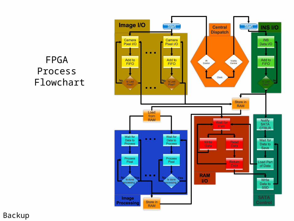
FPGA Process
Flowchart
Backup
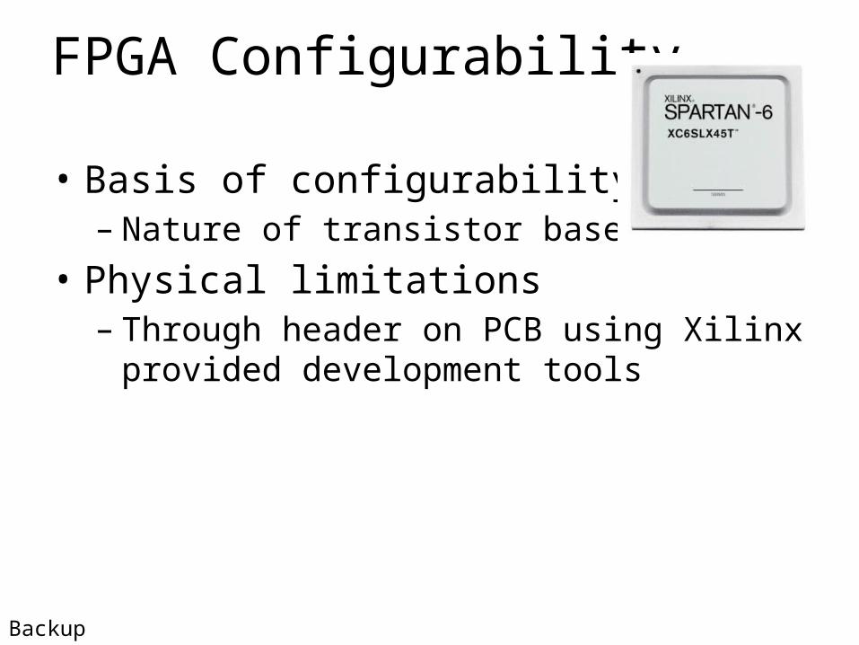
FPGA Configurability
• Basis of configurability– Nature of transistor based FPGA
• Physical limitations– Through header on PCB using Xilinx provided
development tools
Backup
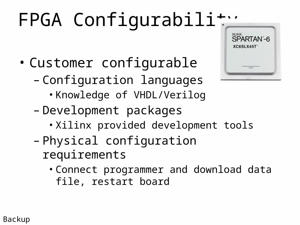
FPGA Configurability
• Customer configurable– Configuration languages• Knowledge of VHDL/Verilog
– Development packages• Xilinx provided development tools
– Physical configuration requirements• Connect programmer and download data file, restart
board
Backup
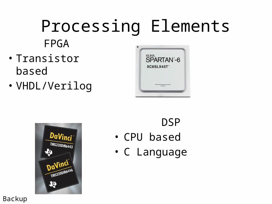
Processing Elements
DSP• CPU based• C Language
FPGA• Transistor based• VHDL/Verilog
Backup
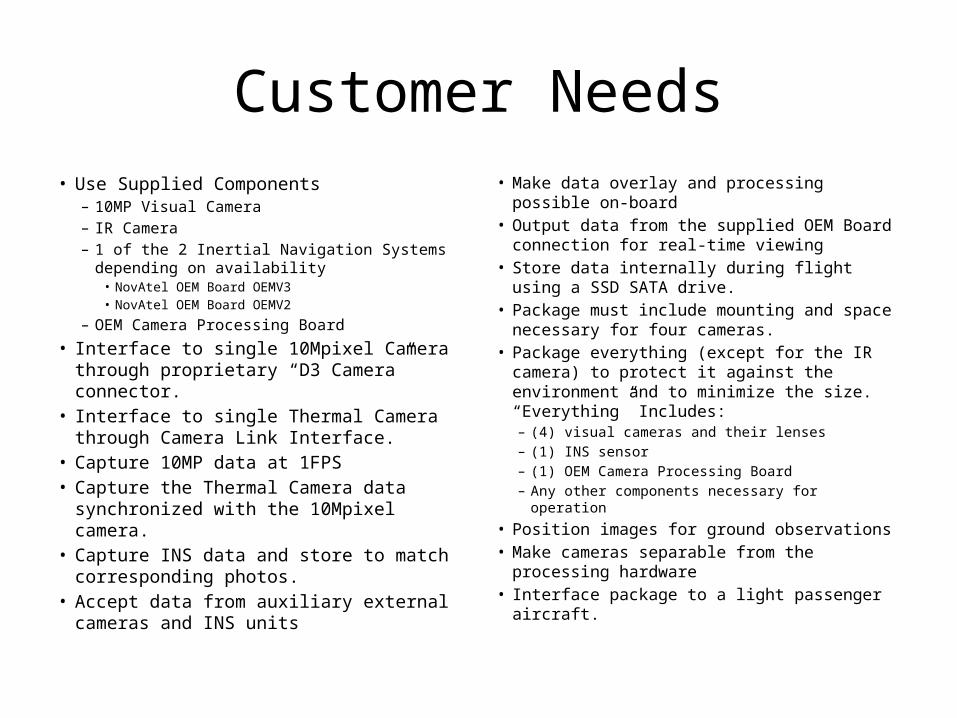
Customer Needs• Use Supplied Components
– 10MP Visual Camera– IR Camera– 1 of the 2 Inertial Navigation Systems
depending on availability • NovAtel OEM Board OEMV3• NovAtel OEM Board OEMV2
– OEM Camera Processing Board
• Interface to single 10Mpixel Camera through proprietary “D3 Camera” connector.
• Interface to single Thermal Camera through Camera Link Interface.
• Capture 10MP data at 1FPS• Capture the Thermal Camera data
synchronized with the 10Mpixel camera. • Capture INS data and store to match
corresponding photos. • Accept data from auxiliary external cameras
and INS units
• Make data overlay and processing possible on-board
• Output data from the supplied OEM Board connection for real-time viewing
• Store data internally during flight using a SSD SATA drive.
• Package must include mounting and space necessary for four cameras.
• Package everything (except for the IR camera) to protect it against the environment and to minimize the size. “Everything” Includes:– (4) visual cameras and their lenses– (1) INS sensor– (1) OEM Camera Processing Board– Any other components necessary for operation
• Position images for ground observations• Make cameras separable from the processing
hardware• Interface package to a light passenger aircraft.
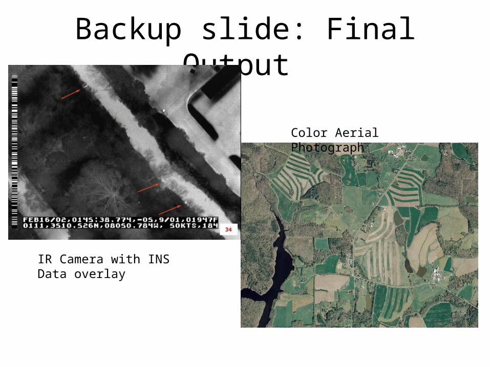
Backup slide: Final Output
IR Camera with INS Data overlay
Color Aerial Photograph
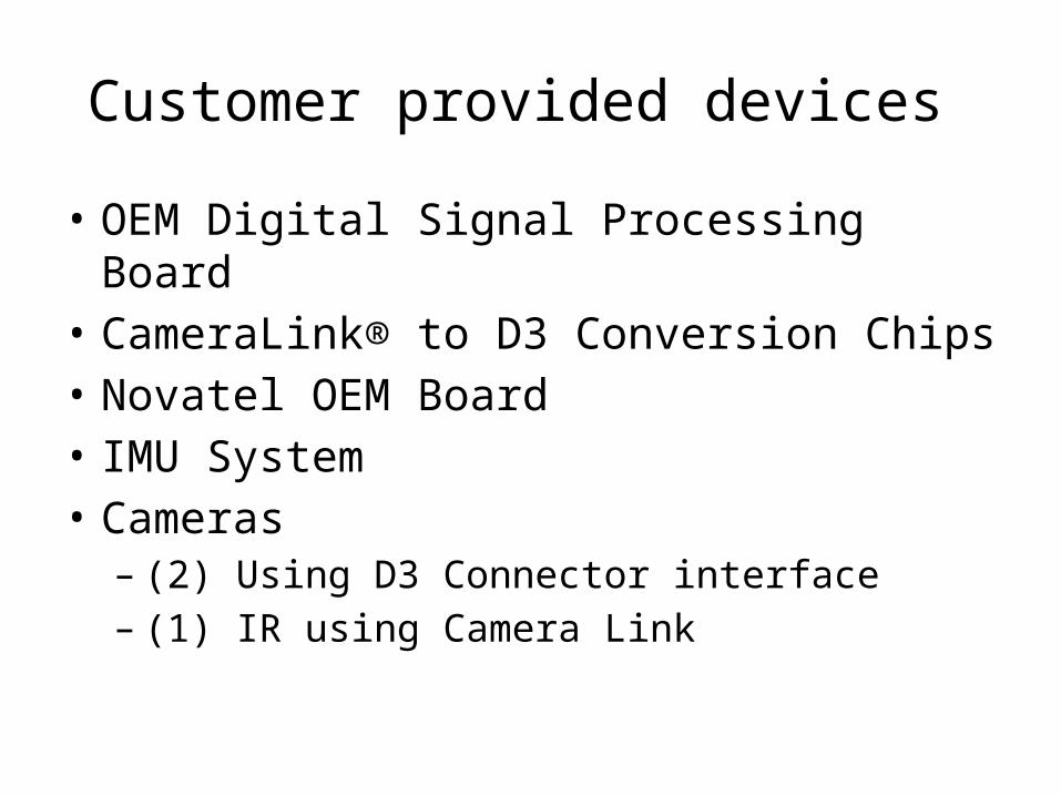
Customer provided devices
• OEM Digital Signal Processing Board• CameraLink® to D3 Conversion Chips• Novatel OEM Board• IMU System• Cameras – (2) Using D3 Connector interface– (1) IR using Camera Link
BACKUP SLIDE
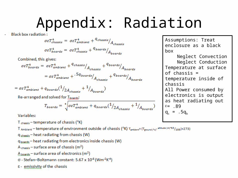
Appendix: RadiationAssumptions: Treat enclosure as a black box
Neglect ConvectionNeglect Conduction
Temperature at surface of chassis = temperature inside of chassisAll Power consumed by electronics is output as heat radiating oute= .89 qc = .5qb
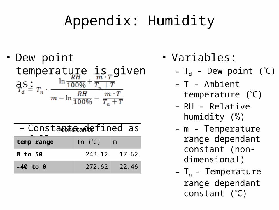
Appendix: Humidity
• Dew point temperature is given as:
– Constants defined as follows:
• Variables: – Td - Dew point (C)– T - Ambient temperature
(C)– RH - Relative humidity (%)– m - Temperature range
dependant constant (non-dimensional)
– Tn - Temperature range dependant constant (C)
constants
temp range Tn (°C) m
0 to 50 243.12 17.62
-40 to 0 272.62 22.46