form no. 3324–980 - toro
TRANSCRIPT

Parts Catalog
Ordering Replacement PartsTo order replacement parts, please supply: the partnumber, the quantity, and the description of eachpart desired.
Understanding Reference NumbersEach identified part in an illustration has a referencenumber. The reference number for a part also appears inthe parts list, along with other information about the part.
This catalog uses two special reference number formats,one to indicate parts in a service assembly and anotherto indicate the quantity of a given part in an illustration.
Service Assembly Reference NumbersParts in service assemblies have reference numbers inthe form a:b. The a represents the reference number ofthe entire service assembly and the b represents asequential number unique to each part within the serviceassembly.
For example, a wheel assembly might be identified byreference number 6, the tire by 6:1, the valve by 6:2,and the wheel by 6:3. When you order the assemblyidentified by reference number 6, you receive all partsidentified by reference numbers 6:1, 6:2, and 6:3.However, you may also order any part individually.
Reference numbers of this type appear in illustrationsand in part lists.
Reference Numbers Indicating QuantityIn an illustration, if a reference number indicates morethan one part, the reference number has the form nX y.The n represents the quantity of the part, the X is themultiplication symbol, and the y represents the referencenumber.
For example, in an illustration, the reference number2X 37 means that two of the parts identified by referencenumber 37 are indicated.
The TORO Company — 2000All Rights Reserved
Form No. 3324–980
Z255Z–Master � with 62” SFS Side Discharge MowerModel No. 74226—210000001 and Up

3324–980
2
ContentsDescription Page Description PageFront Frame Assembly 3. . . . . . . . . . . . . . . . . . . . . Caster and Wheel Assembly 4. . . . . . . . . . . . . . . . Rear Frame and Wheel Assembly 5. . . . . . . . . . . Brake and Wheel Hub Assembly 6. . . . . . . . . . . . Control Panel Assembly 7. . . . . . . . . . . . . . . . . . . . Hydraulic System Assembly 8. . . . . . . . . . . . . . . . Tank and Fuel Line Assembly 10. . . . . . . . . . . . . . . Shield and Clutch Assembly 11. . . . . . . . . . . . . . . . Idler Assembly 13. . . . . . . . . . . . . . . . . . . . . . . . . . . . Electrical System Assembly 14. . . . . . . . . . . . . . . . . Frame and Deck Assembly 15. . . . . . . . . . . . . . . . . Deck, Deflector and Roller Assembly 16. . . . . . . . . Spindle and Pulley Assembly 17. . . . . . . . . . . . . . .
Belts and Idler Arm Assembly 18. . . . . . . . . . . . . . . Stand Assembly 19. . . . . . . . . . . . . . . . . . . . . . . . . . . Crankshaft Assembly 20. . . . . . . . . . . . . . . . . . . . . . Crankcase Assembly 21. . . . . . . . . . . . . . . . . . . . . . Oil Pan/Lubrication Assembly 22. . . . . . . . . . . . . . . Head/Valve/Breather Assembly 23. . . . . . . . . . . . . . Ignition/Electrical Assembly 24. . . . . . . . . . . . . . . . . Blower Housing and Baffle 25. . . . . . . . . . . . . . . . . . Starting System Assembly 26. . . . . . . . . . . . . . . . . . Fuel System Assembly 27. . . . . . . . . . . . . . . . . . . . . Engine Controls Assembly 29. . . . . . . . . . . . . . . . . . Air Intake/Filtration Assembly 30. . . . . . . . . . . . . . . Exhaust Assembly 31. . . . . . . . . . . . . . . . . . . . . . . . .
AccessoriesDescription Model / Part No. Description Model / Part No.High Suspension Seat 74210. . . . . . . . . . . . . . . . . . . . . Foot Lift Assist 78473. . . . . . . . . . . . . . . . . . . . . . . . . . . . Roll Over Protection System Kit 78480. . . . . . . . . . . . .
Hitch Kit 99–8925. . . . . . . . . . . . . . . . . . . . . . . . . . . . . . . Atomic Blade Assembly 104–1303. . . . . . . . . . . . . . . . Stripping Kit 30163. . . . . . . . . . . . . . . . . . . . . . . . . . . . . .
Part Description AbbreviationsPart descriptions in this catalog may include the following abbreviations.
Abbreviation Meaning Abbreviation MeaningAR as required. . . . . . . . . . . . . . . . . ASM assembly. . . . . . . . . . . . . . . . CARR carriage. . . . . . . . . . . . . . DEG degrees. . . . . . . . . . . . . . . . FH flat head. . . . . . . . . . . . . . . . . GA gauge. . . . . . . . . . . . . . . . . HF hex flange. . . . . . . . . . . . . . . . . HH hex head. . . . . . . . . . . . . . . . . HHF hex head flange. . . . . . . . . . . . . . . . HLH hex lag head. . . . . . . . . . . . . . . . HJ hex jam. . . . . . . . . . . . . . . . . . HOC height-of-cut. . . . . . . . . . . . . . . . HS hex socket. . . . . . . . . . . . . . . . . HSBH hex socket button head. . . . . . . . . . . . . . HSFH hex socket flat head. . . . . . . . . . . . . . . HSH hex socket head. . . . . . . . . . . . . . . . HWH hex washer head. . . . . . . . . . . . . . . HWHTF hex washer head. . . . . . . . . . . . .
thread forming
INC incorporated. . . . . . . . . . . . . . . . . LH left hand. . . . . . . . . . . . . . . . . NI nylon insert. . . . . . . . . . . . . . . . . . PPH Phillips pan head. . . . . . . . . . . . . . . . PTH Phillips truss head. . . . . . . . . . . . . . . . PTO power take off. . . . . . . . . . . . . . . . RH right hand. . . . . . . . . . . . . . . . . SFH slotted fillister head. . . . . . . . . . . . . . . . SHH slotted hex head. . . . . . . . . . . . . . . . SQH square head. . . . . . . . . . . . . . . . SHWH slotted hex washer head. . . . . . . . . . . . . . SPH slotted pan head. . . . . . . . . . . . . . . . SRH slotted round head. . . . . . . . . . . . . . . . STD standard. . . . . . . . . . . . . . . . TAP self tapping. . . . . . . . . . . . . . . . TTH Torx truss head. . . . . . . . . . . . . . . . WH wing head. . . . . . . . . . . . . . . . .

3324–980
3
Sheet No.:2
1
1:3
1:2
37
15
3
10
2711
14
22
36
25
23
710
3:2
89
10
11
33
3:4
32
6
34
5
2422
1024
28
26
1213
1924
1716
2420
2930
3331
29
3:5
21
3:318
25
29
3029
1:4
Front Frame AssemblyDescriptionPart No. Qty.Ref. No. DescriptionPart No. Qty.Ref. No.
1 104–5132 1 Frame ASM1:2 1–633818 1 Decal–Warning1:3 1–811010 2 Plug1:4 302–19 5 Fitting–Grease
3 100–6509 1 Floorpan ASM3:2 1–633553 3 Pad–Antiskid3:3 1–633766 1 Decal–Check3:4 98–5954 1 Decal–Missing, Cover3:5 1–633737 1 Decal–Z–Master
5 1–632324–03 1 Lever–Lift6 1–633295 1 Grip–Lever, Lift7 1–632219–03 1 Arm–Lift, Deck8 1–633325 1 Spring–Compression9 3256–24 1 Washer–Flat
10 3296–39 5 Nut–Lock, NI11 32151–103 5 Ring–Snap12 1–633068 2 Arm–Lift, Deck13 3272–10 2 Pin–Cotter14 283–2 2 Pin–Clevis15 1–633889–01 1 Plate–Lift, Deck16 1–632899–01 1 Plate–Lift, Deck17 1–633082 1 Bushing–Lever, Lift18 1–633080 1 Bushing–Lever, Lift19 323–13 1 Screw–HH20 1–633097 1 Pin–Hitch w/Lanyard21 1–806005 1 Pin–Hair
22 323–9 2 Screw–HH23 98–5975 12 Washer–Belleville24 3290–357 15 Nut–Flange, Lock25 323–6 3 Screw–HH26 323–7 12 Screw–HH27 3256–29 4 Washer–Flat28 1–633096 2 Rod–Lift, Deck29 3217–11 8 Nut–Hex30 1–633441 4 Swivel–Deck Mount,
Rear31 3256–7 2 Washer–Flat32 1–633064 2 Spring–Support, Deck33 3218–6 4 Nut–Jam34 3256–7 2 Washer–Flat36 1–633706 1 Decal–Height, Deck37 1–633345 1 Decal–Height, Deck

3324–980
4
Sheet No.:3C–2973
11:6:211:6:3
11:6:1
11:6
11:411:1
11:3
22
21
11:5
1
2
3
4
5
5
4
7
8
11
Caster and Wheel AssemblyDescriptionPart No. Qty.Ref. No. DescriptionPart No. Qty.Ref. No.
1 1–543513 2 Cap–Grease2 3296–51 2 Nut–Lock, NI3 1–633508 6 Washer–Bellville4 254–94 4 Bearing–Taper/Cone5 254–72 4 Bearing–Taper/Cup7 1–543511 2 Seal–Grease8 1–642111–01 2 Caster
11 1–644251 2 Caster Wheel ASM11:1 1–633585 2 Bearing–Cone,
Tapered11:3 1–633959 1 Spacer–Caster, Front11:4 1–633580 2 Seal–Bearing11:5 1–633581 2 Spacer–Bearing11:6 2 Wheel & Tire ASM
11:6:1 1–523009 2 Tire11:6:2 1–633987 2 Wheel11:6:3 1–633584 4 Bearing–Cup
21 325–24 2 Screw–HH22 3296–45 2 Nut–Lock, NI

3324–980
5
Sheet No.:4C–2974
31
13:3
2:4
44
2
2824
27
2:3
11
25
3330
2:5
2:6
34
2:2
2:1
2:7
15
121
5
9
17
1421
20
2316
19
4
26
13
11:2
13:2
13:4
29
22
18
42
12
12:212:110
Rear Frame and Wheel AssemblyDescriptionPart No. Qty.Ref. No. DescriptionPart No. Qty.Ref. No.
1 1–633964–03 1 Stop–Brake, Park2 1–633705 1 Seat w/Tracks
2:1 103–0290 1 Cushion–Bottom, Seat2:2 104–7754 1 Cushion – Back, Seat2:3 1–633710 1 Cushion–Armrest, RH2:4 1–633711 1 Cushion–Armrest, LH2:5 1–543401 4 Spacer–Track2:6 1–643255 1 Track–Seat, 4”2:7 1–633859 1 Frame–Seat
4 322–3 6 Screw–HH5 323–6 2 Screw–HH9 1–633696 1 Cable–Throttle
10 1–603336 1 Control–Choke11 100–4261 1 Rear Frame ASM
11:2 103–0245 1 Decal–Console, Top12 1–633970 2 Wheel & Tire ASM
12:1 1–633993 1 Tire12:2 1–633992 1 Wheel
13 99–4623 1 Console ASM13:2 100–4311 1 Decal–Panel, Control13:3 103–0262 1 Decal–Valve, Fuel13:4 98–4387 1 Decal–Protection, Ear
14 1–632187–03 1 Frame – Seat15 242–50 8 Nut – Lug16 1–633293 1 Rod–Holdup, Seat17 322–5 1 Screw–HH
18 323–21 2 Screw–HH19 3296–2 2 Nut–Lock20 3296–29 1 Nut–Lock21 3296–39 4 Nut–Lock, NI22 1–807513 2 Bolt–CARR23 32128–20 4 Nut–HF24 1–513762 1 Clip–Loom25 1–303335 1 Tie–Plastic26 1–513592 1 Knob–Ball, Red27 321–4 1 Screw–HH28 32128–33 1 Nut–HF29 1–513658 2 Bumper–Catcher,
Grass30 2412–120 2 R–Clamp31 32104–76 2 Screw33 74–0720 1 Tube–Manual34 99–4693 1 Decal–Toro42 1–633736 1 Decal–Toro, Z25544 3256–23 6 Washer–Flat

3324–980
6
Sheet No.:5
1
2
3
3
4
5
10
11
1213
13
13
14
17
18
20
22
23
23
23
25
26
26
27
19
27
19
19
24
1
27
27
23
15:1
286
21
7
30
3129
9
15:2
15
Brake and Wheel Hub AssemblyDescriptionPart No. Qty.Ref. No. DescriptionPart No. Qty.Ref. No.
1 1–513140 2 Bearing–Control2 1–633454 2 Spring–Brake3 1–633477 3 Rod–Brake4 1–634500 1 Brake Lever/Grip ASM5 1–632217–03 1 Shaft–Brake6 103–0352–03 2 Bracket–Brake7 1–523157 2 Washer–Spacer9 103–0355 2 Band–Brake
10 1–633380 4 Spacer–Wheel, Short11 1–633382 4 Spacer–Wheel, Long12 1–633102 2 Bearing–Flange, Side13 1–633131 4 Yoke–Linkage, Brake14 1–633144 2 Pin–Trunion15 103–0590 2 Hub–Wheel w/Studs
15:1 103–0589 1 Hub–Wheel15:2 1–633926 4 Stud–Heel
17 1–633268 1 Grip–Lever, Brake18 323–4 4 Screw–HH19 1–808285 4 Pin–Clevis20 325–17 8 Screw–HH21 1481 2 Fitting–Grease22 103–0131 8 Nut–Square23 3219–3 8 Nut–HH24 3290–357 4 Nut–Flange, Lock25 3253–7 8 Washer–Lock26 3256–4 4 Washer–Flat
27 3272–10 7 Pin–Cotter28 1–806800 2 Pin–Cotter29 322–9 6 Screw–HH30 103–0384 6 Spacer31 103–0374 2 Retainer–Band, Brake

3324–980
7
Sheet No.:6
23
26
29
1 3334
32
3
13
30
34
30
17
3520
27
14
18
11
2615
2
11:1
8
204
25
22
34
2412
16
867
5
34
2826
34
83
34
21
Control Panel AssemblyDescriptionPart No. Qty.Ref. No. DescriptionPart No. Qty.Ref. No.
1 1–303105 2 Yoke–Adjustable2 98–5975 4 Washer–Belleville3 1–523027 2 Damper–Control4 1–543017 2 Balljoint–RH5 1–603735 2 Bushing–Flanged,
Nylon6 1–603737 2 Bolt–Return, Neutral7 1–603807 2 Spring–Return,
Neutral8 1–403180 4 Screw–HH
11 103–0632 1 RH Lever/Grip ASM11:1 1–633257 1 Grip–Control, Motion
12 1–632208–03 2 Arm–Control, Pump13 1–642319 1 Control–Motion, LH14 1–642320 1 Control–Motion, RH15 1–633153 2 Linkage–Pump/Lever16 1–633102 4 Bearing–Flange, Side17 1–633152 2 Balljoint–Thread, LH18 103–0407 2 Arm–Shaft, Control20 322–6 4 Screw–HH21 323–4 8 Screw–HH22 323–6 4 Screw–HH23 323–9 6 Screw–HH24 1–803022 2 Screw25 3296–39 6 Nut–Lock, NI26 3219–2 10 Nut–Hex
27 3220–20 2 Nut–Jam28 3220–2 2 Nut29 3256–2 2 Washer–Flat30 3256–3 4 Washer–Flat32 3272–5 2 Pin–Cotter33 1–808280 2 Pin–Clevis34 32128–20 16 Nut–HF35 3290–357 8 Nut–Flange, Lock
*37 103–0631 1 LH Lever/Grip ASM
* Not illustrated

3324–980
8
Sheet No.:7
11:1
3333:1
12
26
7
46
31
33:1
33:341
28
37
21
35
51
10
40
1
2220
40
4817
3
2:2
6
11:2
30
36 44
2
32
27
3929 45
19
17
25
10
1516
17 8
51
22
20
46
4713
17
2841
11
21
14
47
18
43
38
111
7
934
5 47
24
3216
16
Hydraulic System AssemblyDescriptionPart No. Qty.Ref. No. DescriptionPart No. Qty.Ref. No.
1 1–633774 2 Hose–Upper2 99–4625 1 Hydraulic Tank ASM
2:2 1–523552 1 Decal–Tank, Hydraulic3 1–513006 1 Filter–Head5 1–513167 1 Cap–Reservoir,
Hydraulic6 1–633750 1 Filter–Hydraulic6 1–633752 1 Filter–Winter,
Hydraulic7 1–513840 2 Fitting–90�8 1–522217 1 Low Pressure Hose
ASM9 1–523103 1 Gasket–Cap, Tank
10 1–633786 4 Fitting–90�11 1–523328 2 Motor–Wheel
11:1 1–809036 1 Nut–HH11:2 1–807020 1 Key–Woodruff
*11:99 1–000099 1 Kit–Seal*11:99 1–000139 1 Kit–Bearing
12 1–603384 1 Bushing–Pivot, Idler13 1–603413 1 Spring–Extension14 1–603721 1 Fitting–Tee, Hose15 1–603722 1 Fitting–Tee, Hose16 1–603826 3 Clamp–Hose17 1–603827 5 Clamp–Hose18 1–603987 1 Fitting–Elbow
19 1–603988 1 Fitting–Elbow20 1–603989 2 Fitting–Elbow21 1–603990 4 Fitting–Straight22 1–633775 2 Hose–Lower24 1–632281 1 Hose ASM25 1–632282 1 Hose ASM26 1–632285 1 Hose ASM27 1–632286 1 Hose ASM28 1–633568 2 Sheave29 1–633567 1 Sheave30 1–633749 1 Belt–Drive, Pump31 1–633167 1 Sheave–Idler32 1–633335 2 Hose–Pressure, Low33 1–634277 1 Bearing Arm ASM
33:1 1–513034 2 Sleeve–Bearing33:3 302–40 1 Fitting–Grease
34 321–4 2 Screw–HH35 323–8 1 Screw–HH36 323–9 1 Screw–HH37 1–800805 1 Screw–HH38 323–7 4 Screw–HH39 1–803022 2 Screw40 3242–6 2 Screw–Set, SQH41 3242–4 2 Screw–Set, SQH43 3256–3 1 Washer–Flat44 3256–4 1 Washer–Flat
* Not illustrated

3324–980
9
Sheet No.:7
11:1
3333:1
12
26
7
46
31
33:1
33:341
28
37
21
35
51
10
40
1
2220
40
4817
3
2:2
6
11:2
30
36 44
2
32
27
3929 45
19
17
25
10
1516
17 8
51
22
20
46
4713
17
2841
11
21
14
47
18
43
38
111
7
934
5 47
24
3216
16
Hydraulic System AssemblyDescriptionPart No. Qty.Ref. No. DescriptionPart No. Qty.Ref. No.
45 13–2840 1 Key–Square46 1–807272 2 Key–Machine47 3290–357 8 Nut–Flange, Lock48 32128–33 2 Nut–HF51 1–603841 2 Pump–Hydraulic, RH
*51 80–6130 1 Kit–Seal, Overhaul
* Not illustrated
3324–980
10
Sheet No.:8C–2975
18
3
15
4
17
6
8
3
1
15
18
13
121
1
1
8
UNIT FRONT
2019
16
9201417
11
10
5
22221
2423
5:3
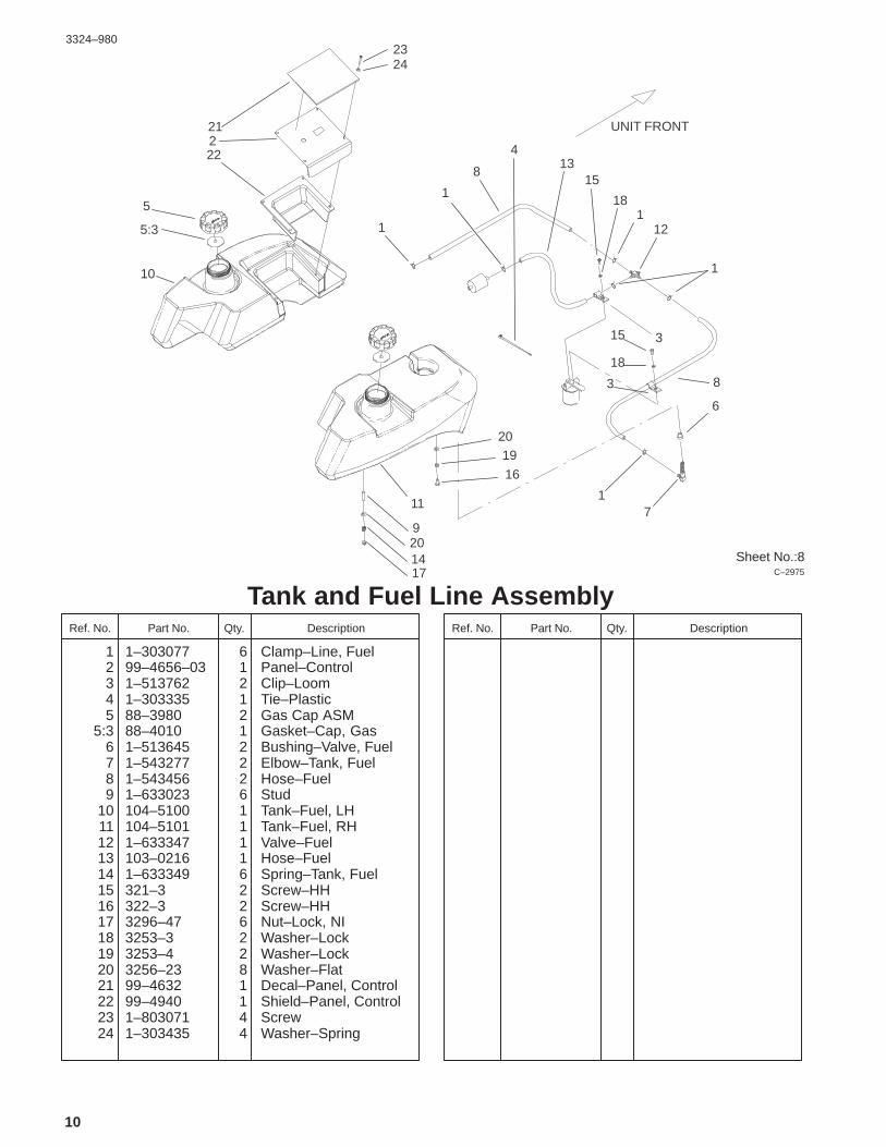
Tank and Fuel Line AssemblyDescriptionPart No. Qty.Ref. No. DescriptionPart No. Qty.Ref. No.
1 1–303077 6 Clamp–Line, Fuel2 99–4656–03 1 Panel–Control3 1–513762 2 Clip–Loom4 1–303335 1 Tie–Plastic5 88–3980 2 Gas Cap ASM
5:3 88–4010 1 Gasket–Cap, Gas6 1–513645 2 Bushing–Valve, Fuel7 1–543277 2 Elbow–Tank, Fuel8 1–543456 2 Hose–Fuel9 1–633023 6 Stud
10 104–5100 1 Tank–Fuel, LH11 104–5101 1 Tank–Fuel, RH12 1–633347 1 Valve–Fuel13 103–0216 1 Hose–Fuel14 1–633349 6 Spring–Tank, Fuel15 321–3 2 Screw–HH16 322–3 2 Screw–HH17 3296–47 6 Nut–Lock, NI18 3253–3 2 Washer–Lock19 3253–4 2 Washer–Lock20 3256–23 8 Washer–Flat21 99–4632 1 Decal–Panel, Control22 99–4940 1 Shield–Panel, Control23 1–803071 4 Screw24 1–303435 4 Washer–Spring
3324–980
11
Sheet No.:9C–2976
35
40
36
3717
2432
14:4
14:3
14:243:3
43:6
43:4
43:243
43:1
43:5
44
1213
42
24
227
6
39
14
14:1
9:1
384
5
34
14:5
301
31
32
20
25
9 10
22 29 22
33
411
81
33
1
3
27
2229
27
27
384
11:2:311:2:2
11:2:1
11:1
11:3
11:211
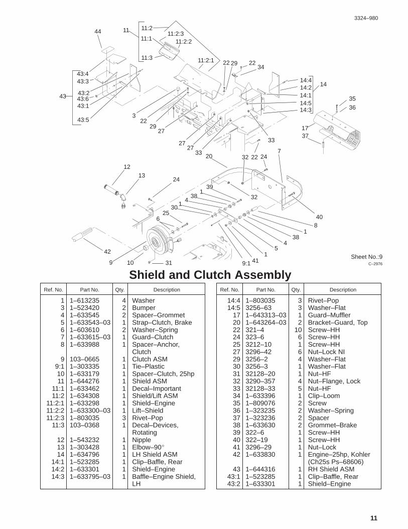
Shield and Clutch AssemblyDescriptionPart No. Qty.Ref. No. DescriptionPart No. Qty.Ref. No.
1 1–613235 4 Washer3 1–523420 2 Bumper4 1–633545 2 Spacer–Grommet5 1–633543–03 1 Strap–Clutch, Brake6 1–603610 2 Washer–Spring7 1–633615–03 1 Guard–Clutch8 1–633988 1 Spacer–Anchor,
Clutch9 103–0665 1 Clutch ASM
9:1 1–303335 1 Tie–Plastic10 1–633179 1 Spacer–Clutch, 25hp11 1–644276 1 Shield ASM
11:1 1–633462 1 Decal–Important11:2 1–634308 1 Shield/Lift ASM
11:2:1 1–633298 1 Shield–Engine11:2:2 1–633300–03 1 Lift–Shield11:2:3 1–803035 3 Rivet–Pop
11:3 103–0368 1 Decal–Devices,Rotating
12 1–543232 1 Nipple13 1–303428 1 Elbow–90�14 1–634796 1 LH Shield ASM
14:1 1–523285 1 Clip–Baffle, Rear14:2 1–633301 1 Shield–Engine14:3 1–633795–03 1 Baffle–Engine Shield,
LH
14:4 1–803035 3 Rivet–Pop14:5 3256–63 3 Washer–Flat
17 1–643313–03 1 Guard–Muffler20 1–643264–03 2 Bracket–Guard, Top22 321–4 10 Screw–HH24 323–6 6 Screw–HH25 3212–10 1 Screw–HH27 3296–42 6 Nut–Lock NI29 3256–2 4 Washer–Flat30 3256–3 1 Washer–Flat31 32128–20 1 Nut–HF32 3290–357 4 Nut–Flange, Lock33 32128–33 5 Nut–HF34 1–633396 1 Clip–Loom35 1–809076 2 Screw36 1–323235 2 Washer–Spring37 1–323236 2 Spacer38 1–633630 2 Grommet–Brake39 322–6 1 Screw–HH40 322–19 1 Screw–HH41 3296–29 1 Nut–Lock42 1–633830 1 Engine–25hp, Kohler
(Ch25s Ps–68606)43 1–644316 1 RH Shield ASM
43:1 1–523285 1 Clip–Baffle, Rear43:2 1–633301 1 Shield–Engine
3324–980
12
Sheet No.:9C–2976
35
40
36
3717
2432
14:4
14:3
14:243:3
43:6
43:4
43:243
43:1
43:5
44
1213
42
24
227
6
39
14
14:1
9:1
384
5
34
14:5
301
31
32
20
25
9 10
22 29 22
33
411
81
33
1
3
27
2229
27
27
384
11:2:311:2:2
11:2:1
11:1
11:3
11:211
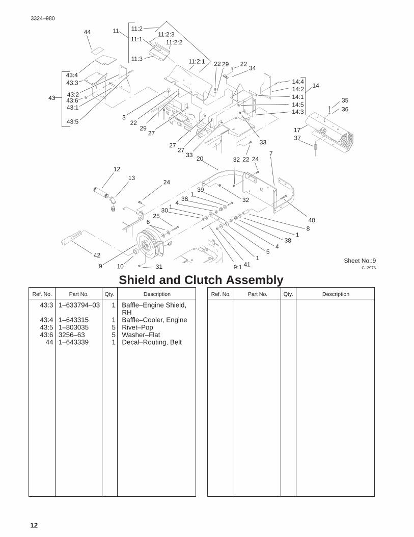
Shield and Clutch AssemblyDescriptionPart No. Qty.Ref. No. DescriptionPart No. Qty.Ref. No.
43:3 1–633794–03 1 Baffle–Engine Shield,RH
43:4 1–643315 1 Baffle–Cooler, Engine43:5 1–803035 5 Rivet–Pop43:6 3256–63 5 Washer–Flat
44 1–643339 1 Decal–Routing, Belt

3324–980
13
Sheet No.:10
14
7
18
24
21
21 14:1 1915
14:1
21
24
21
1123
117
2021
16
14:3
91021
6
24
16
1520
9 1
2012
21
Idler AssemblyDescriptionPart No. Qty.Ref. No. DescriptionPart No. Qty.Ref. No.
1 98–5975 5 Washer–Belleville6 1–603050 1 Spacer7 1–603384 1 Bushing–Pivot, Idler9 1–603496 2 Bushing–Idler
10 99–4638 1 Idler11 1–603402 1 Spring–Extension12 1–633166 1 V–Belt–Idler14 99–4677 1 Idler Arm ASM
14:1 1–513034 2 Sleeve–Bearing14:3 302–40 1 Fitting–Grease
15 323–11 2 Screw–HH16 323–9 5 Screw–HH17 323–13 1 Screw–HH18 1–800805 1 Screw–HH19 3296–39 1 Nut–Lock, NI20 3256–24 3 Washer–Flat21 3290–357 10 Nut–Flange, Lock23 1–603401 1 Spacer–Fender24 3256–4 3 Washer–Flat

3324–980
14
Sheet No.:11
28
21
28
21
21
12
12
30
11
11
26
26
26
33
34
3333
16
16
22 33
3231
29
27
24
20
20
18
17
17
12
17
1716
16
16
16
1615
14
12
11
11
109
8
8
7
6
5
4
3
3
2
1
13 2536
TO ENGINE
TO CLUTCH
19
23
23:123:2
32:2
Electrical System AssemblyDescriptionPart No. Qty.Ref. No. DescriptionPart No. Qty.Ref. No.
1 1–633652–03 1 Strap–Holddown,Battery
2 1–603479 1 Battery3 1–543792 2 Wingnut4 1–633307 1 Wire–Ground5 1–543391 1 Insulator–Battery6 1–800282 1 Screw–HH7 3256–2 2 Washer–Flat8 32128–20 2 Nut–HF9 1–523415 1 Spring–Switch, Seat
10 1–522424–03 1 Mount–Spring, Seat11 321–4 6 Screw–HH12 32128–33 6 Nut–HF13 63–8360 2 Key–Ignition14 1–513152 1 Switch–Closed,
Normally15 1–513180 1 Plate–Switch, Seat16 3290–500 14 Screw–PPH17 1–633181 4 Plate–Tapped18 1–816001 2 Fuse–Type, Blade19 1–633111 1 Switch20 1–513051 2 Switch–Open,
Normally21 1–303287 5 Tie–Plastic22 100–6186 1 Module–Delay, Seat23 88–9830 1 Switch–Ignition
23:1 3254–5 1 Washer–Lock, Internal23:2 218–461 1 Nut–HH
24 1–513374 1 Meter–Hours25 1–633673 1 Switch–Delta26 1–633396 3 Clip–Loom27 100–4340 1 Harness–Wire28 1–303335 2 Tie–Plastic29 1–523281 1 Wire–Starter30 1–543393 1 Insulator–Solenoid31 1–633651 2 Bolt–Holddown32 1–644427 1 Tilt Switch ASM
32:2 1–643401 1 Decal–Switch,Mercury
33 3296–2 6 Nut–Lock34 1–643275 2 Relay36 103–0499 1 Seal–Switch, Ignition

3324–980
15
Sheet No.:12
1
1
2
2
48
7
5
10
9
6
1
2
1
121113
1
1
2
3
1 1
Frame and Deck AssemblyDescriptionPart No. Qty.Ref. No. DescriptionPart No. Qty.Ref. No.
1 32128–37 16 Nut–HF2 324–6 8 Screw–HH3 1–633447 4 Chain–Lift, Deck4 302–19 4 Fitting–Grease5 3217–11 2 Nut–Hex6 3253–8 2 Washer–Lock7 327–11 2 Screw–HH8 1–633029 2 Balljoint–Spherical9 3219–6 2 Nut–Hex
10 103–1072–01 2 Strut–Deck11 1–632199–01 2 Pin–Strut, Deck12 322–3 2 Screw–HH13 3296–29 2 Nut–Lock

3324–980
16
Sheet No.:32
8 16
6
57 8
13
8
9
10
1
9:2
10:2
1:9
1:2
1:8
1:3
1:10
1:7
1:41:8 1:61:8
4
C–2977
Deck, Deflector and Roller AssemblyDescriptionPart No. Qty.Ref. No. DescriptionPart No. Qty.Ref. No.
1 104–7762 1 Deck ASM1:2 43–8480 1 Decal–Danger1:3 98–3798 1 Decal–Wheel, Gage1:4 66–1340 1 Decal–Danger1:6 99–4686 1 Decal–Routing, Belt1:7 99–4619 1 Decal–Sfs1:8 98–5954 3 Decal–Missing, Cover1:9 93–7818 1 Decal–Torque, Blade
1:10 99–4620 1 Decal–Deck4 323–4 4 Screw–HH5 68–2730 6 Gage–Wheel6 99–2842 6 Spacer–Wheel7 1–373034 6 Washer–Swivel8 3290–357 18 Nut–Flange, Lock9 98–5955 1 LH Cover ASM
9:2 67–5360 1 Decal–Danger10 98–5956 1 RH Cover ASM
10:2 67–5360 1 Decal–Danger13 323–2 2 Screw–HH16 98–5975 6 Washer–Belleville

3324–980
17
Sheet No.:33
3
77:2
426
8
11
14
13
22:122:222:3
22:4
23
9
10
5
22
21:221:921:10
21:8
21
22:722:5
22:6
22:722:822:9
22:10
22
17 18
21:6
21:7
21:4
21:621:5
21:1
17
15
21
19
2020
Spindle and Pulley AssemblyDescriptionPart No. Qty.Ref. No. DescriptionPart No. Qty.Ref. No.
3 322–50 1 Screw–Cap4 104–8554 1 Spring–Torsion5 99–8933 1 Guide–Belt7 104–7763 1 Deflector ASM
7:2 54–9220 1 Decal–Danger8 3296–29 1 Nut–Lock9 323–8 1 Screw–HH
10 3256–3 1 Washer–Flat11 32128–17 8 Nut–Lock, Flange13 3290–321 8 Screw–HWH14 249–21 4 Clamp–Slotted15 92–5816 2 Bolt–Blade17 1–513435 3 Washer–Spring18 44–6250 3 Blade19 3256–24 1 Washer–Flat20 32128–21 18 Nut–HF21 99–4640 2 Outer Spindle ASM
21:1 27–0920 1 Shaft–Spindle21:2 302–2 1 Fitting–Grease21:4 46–8530 1 Bearing ASM21:5 27–0950 1 Spacer–Bearing,
Spindle21:6 253–139 2 Seal–Oil21:7 61–4160 1 Housing–Spindle21:8 99–4614 1 Pulley & Hub21:9 32146–20 1 Nut–Jam
21:10 7–4150 1 Washer–Pinion22 99–4944 1 Middle Spindle ASM
22:1 302–2 1 Fitting–Grease22:2 32146–20 1 Nut–Jam22:3 92–5836 1 Washer–Axle22:4 99–4939 1 Pulley & Hub ASM22:5 61–4160 1 Housing–Spindle22:6 46–8530 1 Bearing ASM22:7 253–139 2 Seal–Oil22:8 27–0950 1 Spacer–Bearing,
Spindle22:9 51–3551 1 Shaft–Spindle
22:10 92–5816 1 Bolt–Blade23 3231–22 17 Screw–CARR26 104–8555 1 Spacer–Deflector,
Mounting

3324–980
18
Sheet No.:34
21
26
20
21 19 26
76
2
1
11
34
5
9
810
13
17
16
14
25
16
152318
22
24
9
21
12
5:2
Belt and Idler Arm AssemblyDescriptionPart No. Qty.Ref. No. DescriptionPart No. Qty.Ref. No.
1 65–5940 1 Pulley–Idler2 7–0081 1 Washer–Flat3 3296–71 1 Nut–Lock NI4 3256–27 1 Washer–Flat5 27–8580 1 Idler Socket & Bushing
ASM5:2 27–8490 1 Bushing–Rubber, Idler
6 65–5950 1 Bushing–Pulley7 3211–8 1 Screw–HH8 5–1077 1 Key–Square9 3290–357 3 Nut–Flange, Lock
10 44–6301 1 Plate–Idler, LH11 3296–5 1 Nut–Lock, NI12 44–6260 1 V–Belt13 99–4647 1 V–Belt–Drive, Deck14 99–4659 1 Spacer–Bracket15 1–653189 1 Plate–Guide, Belt16 98–5975 2 Washer–Belleville17 323–42 1 Screw–HH18 1–413099 1 Pulley–Idler19 99–2833–03 1 Baffle–Front, LH20 99–2834–03 1 Baffle–Front, RH21 32128–20 10 Nut–HF22 322–3 4 Screw–HH23 1–653190 1 Spacer24 99–4684–01 1 Bracket–Pulley
25 323–11 1 Screw–HH26 3230–18 6 Screw–CARR

3324–980
19
Sheet No.:51
12
1
2
3
4
5
6
10
78
13
9
11
14
15
Stand AssemblyDescriptionPart No. Qty.Ref. No. DescriptionPart No. Qty.Ref. No.
1 322–13 1 Screw–HH2 100–9699–01 1 Bracket–Cradle3 3296–29 1 Nut–Lock4 100–9695–01 1 Leg ASM5 283–55 1 Pin–Clevis6 100–9692–01 1 Pivot Pin ASM7 323–8 1 Screw–HH8 100–9686–01 1 Bracket–Latch9 3–6781 2 Washer–Thrust
10 283–71 1 Pin–Lynch11 3290–355 1 Pin–Hair12 104–7765 1 Cushion–Rubber13 3296–39 1 Nut–Lock, NI14 104–7758 1 Decal–Z Stand15 104–7759 1 Decal–warning

3324–980
20
�
�
Crankshaft Assembly(Engine: Kohler CH25S PS–68606)
DescriptionPart No. Qty.Ref. No. DescriptionPart No. Qty.Ref. No.
1 24 014 06 1 Crankshaft(Incl. Ref.# 2)
2 52 139 09 1 Plug–Cup
Obtain parts from Kohler
3324–980
21
�
�
�
�
�
�
�
��
��
��
��
��
��
��
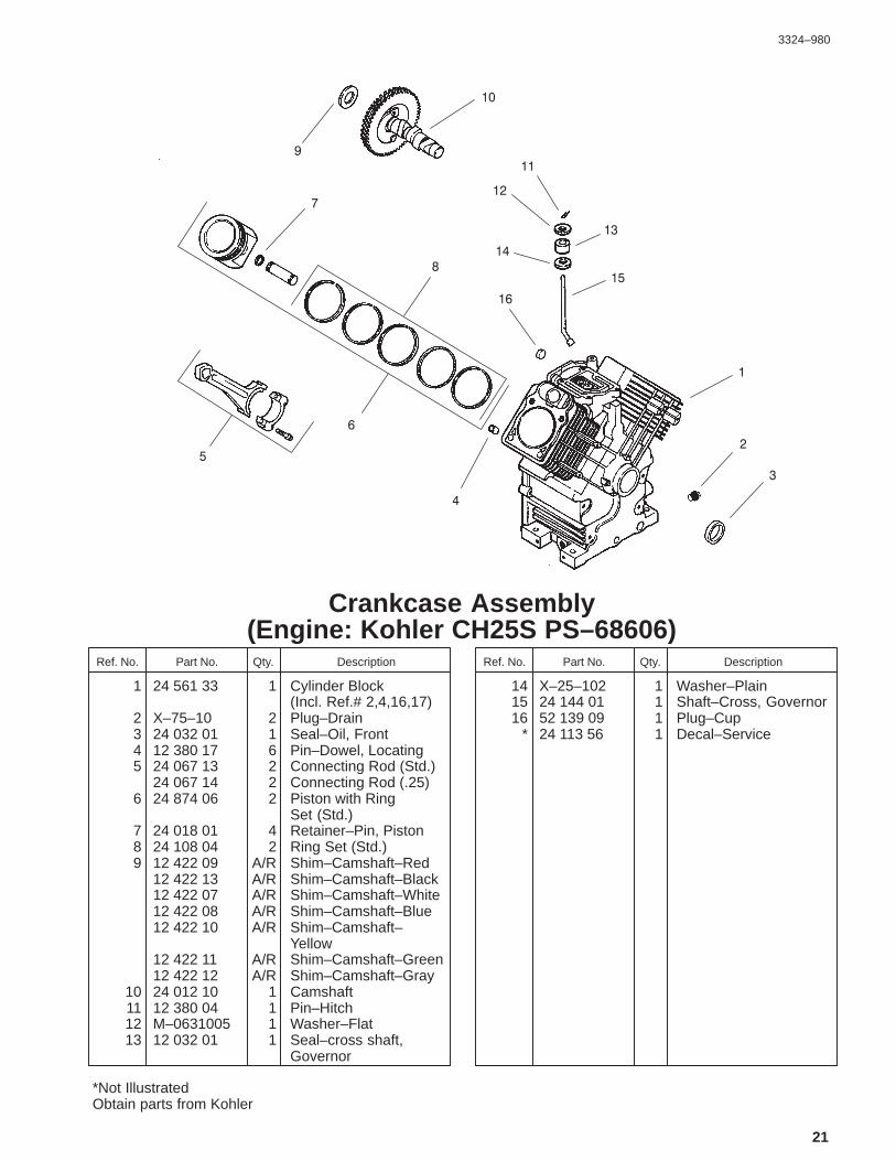
Crankcase Assembly(Engine: Kohler CH25S PS–68606)
DescriptionPart No. Qty.Ref. No. DescriptionPart No. Qty.Ref. No.
1 24 561 33 1 Cylinder Block (Incl. Ref.# 2,4,16,17)
2 X–75–10 2 Plug–Drain3 24 032 01 1 Seal–Oil, Front4 12 380 17 6 Pin–Dowel, Locating5 24 067 13 2 Connecting Rod (Std.)
24 067 14 2 Connecting Rod (.25)6 24 874 06 2 Piston with Ring
Set (Std.)7 24 018 01 4 Retainer–Pin, Piston8 24 108 04 2 Ring Set (Std.)9 12 422 09 A/R Shim–Camshaft–Red
12 422 13 A/R Shim–Camshaft–Black12 422 07 A/R Shim–Camshaft–White12 422 08 A/R Shim–Camshaft–Blue12 422 10 A/R Shim–Camshaft–
Yellow12 422 11 A/R Shim–Camshaft–Green12 422 12 A/R Shim–Camshaft–Gray
10 24 012 10 1 Camshaft11 12 380 04 1 Pin–Hitch12 M–0631005 1 Washer–Flat13 12 032 01 1 Seal–cross shaft,
Governor
14 X–25–102 1 Washer–Plain15 24 144 01 1 Shaft–Cross, Governor16 52 139 09 1 Plug–Cup
* 24 113 56 1 Decal–Service
*Not IllustratedObtain parts from Kohler

3324–980
22
��
��
����
�
�
��
��
��
����
�
�
�
�
�
�
��
��
��
��
��
��
�
Oil Pan/Lubrication Assembly(Engine: Kohler CH25S PS–68606)
DescriptionPart No. Qty.Ref. No. DescriptionPart No. Qty.Ref. No.
1 24 009 83 1 Closure Plate ASM(Incl. Ref.# 2–12)
2 24 038 06 1 Dipstick3 24 123 08 1 Tube–Dipstick4 24 043 12 1 Kit–Gear, Governor
(Incl. Ref.# 5)5 12 380 01 1 Pin–Regulating,
Governor6 52 448 02 1 Tab–Locking7 12 144 02 1 Shaft–Gear, Governor8 52 032 08 1 Seal–Oil (PTO end)9 X–75–23 2 Plug–Pipe, 1/8”
10 24 153 08 1 O–Ring11 24 393 10 1 Oil Pump ASM
(Incl. Ref.# 12,13)12 24 153 01 1 O–Ring–pick–up, Oil13 24 381 04 1 Pick–up–Oil14 M–0631005 2 Washer–Plain, 6mm15 M–0645025 2 Screw–HF16 54 755 14 1 Kit–Cooler, Oil
(Incl. Ref.# 17–21)17 24 253 17 1 O–Ring18 24 594 15 1 Cooler–Oil19 24 086 12 2 Screw–Hex
20 24 136 05 1 Nipple–Filter, Oil21 24 100 01 2 Nut–Plastic22 52 050 02 1 Filter–Oil23 25 155 02 1 Connector24 24 099 03 1 Switch–Pressure25 24 086 16 9 Screw–HF26 24 086 17 1 Screw–HF
* 24 113 25 1 Decal–Cooler, Oil
*Not IllustratedObtain parts from Kohler

3324–980
23
����
��
����
��
�
�
�
�
�
�
�
��
��
��
�
�
��
��
��
��
����
��
���
�
��
��
��
��
��
��
�
�
Head/Valve/Breather Assembly(Engine: Kohler CH25S PS–68606)
DescriptionPart No. Qty.Ref. No. DescriptionPart No. Qty.Ref. No.
1 24 755 74 1 Kit–Valve Cover, Plain(Incl. Ref.# 2, 3)
2 24 086 32 4 Screw–Shoulder3 24 153 16 1 O–Ring–Cover, Valve4 24 445 01 1 Strap–Lifting5 12 755 03 4 Kit–Retainer6 12 173 01 4 Cap–Spring, Valve7 24 089 02 4 Spring–Valve8 235011 4 Retainer–Spring9 24 032 05 2 Seal–Stem, Valve
10 24 318 13 1 #1 Cylinder Head ASM11 24 017 01 2 Valve–Intake ( Std.)
24 017 02 2 Valve–Intake (.25)12 24 016 01 2 Valve–Exhaust (Std.)
24 016 02 2 Valve–Exhaust (.25)13 24 755 66 1 Kit–Train, Valve
(Incl. Ref.# 15,18,19)14 12 351 02 4 Lifter–Valve15 24 411 05 4 Rod–Push16 24 041 37 2 Gasket–Head, Cylinder17 24 318 14 1 #2 Cylinder Head ASM18 25 186 01 4 Arm–Rocker19 24 599 01 4 Pivot–Arm, Rocker20 M–0640034 4 Screw–HF
21 24 086 44 8 Screw–HF
22 24 755 75 1 Kit–Valve Cover, Oil Fill(Incl. Ref.# 2, 3, 23)
23 24 153 09 1 O–Ring24 24 755 46 1 Kit–Cap, Oil Fill
(Incl. Ref.# 25)25 12 153 03 1 O–Ring–Cap, Oil Fill26 24 402 03 1 Reed–Breather27 12 018 01 1 Retainer–Reed,
Breather28 M–0545010 1 Screw–HF29 24 050 01 1 Filter–Breather30 24 033 01 1 Kit–Bbreather
(Incl. Ref.# 31–33)31 X–75–23 1 Plug–Pipe, Allen Head32 24 041 23 1 Gasket–Breather33 24 096 02 1 Cover–Breather34 M–0645020 4 Screw–HF35 X–426–9 1 Clamp–Breather36 24 326 06 1 Hose–Breather
Obtain parts from Kohler

3324–980
24
�
�
��
����
��
��
��
�
�
�
�
���
�
��
����
��
��
��
��
��
��
��
Ignition/Electrical Assembly(Engine: Kohler CH25S PS–68606)
DescriptionPart No. Qty.Ref. No. DescriptionPart No. Qty.Ref. No.
1 54 755 09 1 Kit–Stator, 15 amp(Incl. Ref.# 24 126 71)
2 M–0548025 2 Screw–Cap, Hex3 24 584 11 2 Module–Ignition4 M–0561025 4 Screw–HSH5 24 025 03 1 Flywheel6 X–42–15 1 Key7 12 468 03 1 Washer–Plain, 3/8”8 12 086 14 1 Screw–HF9 24 157 03 1 Fan
10 24 100 02 2 Nut–Plastic11 24 584 09 1 Module–Advance,
Spark12 24 086 41 2 Screw–Head, Phillips13 24 755 08 1 Kit–Drive Shaft, Front
(Incl. Ref.# 14)14 M–0839025 4 Screw–HF15 24 468 11 4 Washer–Spring, 10mm16 24 112 14 4 Spacer17 24 141 06 1 Ring–Support18 24 162 22 1 Screen–Grass19 X–25–53 4 Washer–Plain, 1/4”20 M–0603100 4 Screw–Hex21 24 086 18 2 Screw–Head, Phillips
22 X–25–92 2 Washer–Plain, 3/16”
23 25 403 03 1 Rectifier–Regulator15amp
24 236602 1 Connector25 12 132 06 2 Plug–Spark26 47 154 01 1 Clip–Cable27 X–25–63 1 Washer–Plain, 1/4”28 48 154 02 1 Clip–Cable
* 25 518 28 1 Lead–Black, 4”(18 gauge – insulatedgrip barrel eyeletterminals)
* 24 176 38 1 Harness–Wiring* 24 755 56 1 Kit–Wiring
(Includes Terminal#25 542 17 & TieX–468–1)
* 24 126 71 1 Bracket–Wire, Stator* X–22–11 1 Washer–Lock
*Not IllustratedObtain parts from Kohler

3324–980
25
��
��
��
��
��
�
� �
�
�
��
��
��
�
�
Blower Housing and Baffle(Engine: Kohler CH25S PS–68606)
DescriptionPart No. Qty.Ref. No. DescriptionPart No. Qty.Ref. No.
1 24 027 40 1 Housing–Blower(Incl. Ref.# 2–5)
2 24 100 02 2 Nut–Plastic3 25 139 16 1 Button–Plug4 25 086 43 1 Screw–Set5 24 100 01 2 Nut–Plastic6 M–0551016 1 Screw–HF7 M–0545016 5 Screw–HF8 M–0567020 2 Screw–HF9 24 146 11 1 Plate–Backing,
#2 side10 M–0645016 6 Screw–HF11 24 063 39 1 Baffle– Cylinder Barrel,
#2 side12 24 063 17 1 Baffle–Valley, #2 Side13 M–0545010 2 Screw–HF14 24 063 24 1 Baffle–Valley, #1 Side15 24 063 30 1 Baffle–Cylinder Barrel,
#1 Side16 24 146 08 1 Plate–Backing,
#1 Side* 24 113 69 1 Decal–HP
*Not IllustratedObtain parts from Kohler

3324–980
26
� �
�
�
�
�
�
��
��
��
�
��
��
����
��
Starting System Assembly(Engine: Kohler CH25S PS–68606)
DescriptionPart No. Qty.Ref. No. DescriptionPart No. Qty.Ref. No.
1 M–0841080 1 Nut–HF2 M–0839080 2 Screw–HF3 24 098 01 1 Starter Solenoid Shift
ASM (Incl. Ref.# 4–18)4 24 081 04 1 Drive–Cap, End5 52 100 10 2 Nut–Starter6 12 090 10 1 Lever–Drive, Starter7 24 755 84 1 Kit–Repair, Starter8 12 239 01 1 Drive–Pinion9 52 435 02 1 Solenoid
10 52 100 09 1 Nut–Starter11 12 170 04 1 Armature–Starter12 12 471 01 1 Frame13 52 221 01 1 Kit–Brush & Spring
(Incl. Ref. # 15)14 52 323 03 1 Holder–Brush15 52 089 09 4 Spring–Brush16 52 168 01 1 Insulator17 52 211 05 2 Bolt–Thru18 24 301 01 1 Commutator–Cap, End
Obtain parts from Kohler

3324–980
27
��
�
�
�
�
�
��
��
��
��
��
�
��
��
��
��
���� ��
��
�
��
��
��
��
��
��
��
��
�
��
��
��
�
�
�
��
��
�
�
��
��
�
�
��
��
Fuel System Assembly(Engine: Kohler CH25S PS–68606)
DescriptionPart No. Qty.Ref. No. DescriptionPart No. Qty.Ref. No.
1 25 353 10 2 Line–Fuel, 9”2 X–426–9 6 Clamp–Hose3 24 853 34 1 Kit–Carburetor
(Incl. Ref.# 4–6)4 24 041 06 1 Gasket–Base, Air
Cleaner{5 24 053 34 1 Carburetor ASM6 24 041 17 1 Gasket–Carburetor7 M–0651030 2 Screw–HF8 24 050 02 1 Filter–Fuel9 25 353 15 1 Line–Fuel
10 24 100 01 2 Nut–Plastic11 24 393 04 1 Pump–Fuel–Pulse12 24 086 12 2 Screw–Hex13 24 353 02 1 Line–Fuel, 15–1/2”14 M–0650012 1 Screw–HF15 47 154 01 1 Clip–Cable18 24 154 01 1 Clip–Needle Valve,
Inlet19 24 462 01 1 Valve–Needle, Inlet20 24 086 09 4 Screw21 24 041 09 1 Gasket–Body,
Carburetor22 24 153 02 1 O–Ring–Jet, Slow
23 24 337 29 1 Jet–Slow24 24 757 02 1 Kit–Repair, Float25 24 081 05 1 Housing–Pump26 24 757 08 1 Kit–Repair, Accelerator
Pump27 24 079 07 1 Linkage–Rod28 24 757 09 1 Kit Repair–Diagram,
Accelerator Pump29 24 090 16 1 Lever–Rod30 24 079 06 1 Linkage–Rod31 24 089 27 1 Spring–Linkage32 24 090 15 1 Lever–Linkage33 24 337 30 1 Jet–Main34 24 086 10 1 Screw–Adjustment,
Idle Speed35 24 089 10 1 Spring–Adjustment,
Idle Speed36 24 757 01 1 Solenoid ASM Kit
(Incl. Ref.# 37–42)37 24 153 06 1 O–Ring–Solenoid38 24 521 01 1 Seat–Solenoid39 24 153 05 1 O–Ring–Solenoid40 24 153 04 1 O–Ring–Solenoid41 24 435 01 1 Solenoid42 24 086 07 2 Screw
*Not IllustratedObtain parts from Kohler

3324–980
28
��
�
�
�
�
�
��
��
��
��
��
�
��
��
��
��
���� ��
��
�
��
��
��
��
��
��
��
��
�
��
��
��
�
�
�
��
��
�
�
��
��
�
�
��
��
Fuel System Assembly (Continued)(Engine: Kohler CH25S PS–68606)
DescriptionPart No. Qty.Ref. No. DescriptionPart No. Qty.Ref. No.
43 24 089 11 1 Spring–Adjustment,Idle
44 24 368 01 1 Needle–Adjustment,Idle
* 24 757 03 1 Kit–Repair, Carburetor* 24 757 07 1 Kit–Repair, Choke* (Incl. Ref.# 17)
24 173 02 1 Cap–Lever, Choke
*Not Illustrated�For Information Only–Not Available SeparatelyObtain Parts From Kohler

3324–980
29
�
�
�
�
�
��
��
��
�
�
��
��
��
��
��
��
��
��
��
�
�
��
��
Engine Controls Assembly(Engine: Kohler CH25S PS–68606)
DescriptionPart No. Qty.Ref. No. DescriptionPart No. Qty.Ref. No.
1 M–0547050 1 Nut–Lock, Hex2 24 089 03 1 Spring–Return, Choke3 M–0645016 4 Screw–HF4 24 126 56 1 Bracket–Control5 24 468 01 3 Washer–Plain6 24 090 07 1 Lever–Actuator,
Throttle7 12 237 01 2 Clamp–Cable8 M–0545016 2 Screw–HF9 24 090 03 1 Lever–Control, Throttle
10 M–0446030 1 Nut–Hex11 M–0401030 1 Screw–Hex, Cap12 24 079 02 1 Linkage–Choke13 24 090 05 1 Lever–Choke14 41 468 03 1 Washer–Spring15 M–0545020 1 Screw–HF16 24 089 38 1 Spring–Limiter, Throttle17 24 089 15 1 Spring–Governor18 SM–0642025 1 Screw–HF19 24 090 14 1 Lever–Governor20 M–0641060 1 Nut–HF21 25 158 11 1 Bushing–Retaining,
Linkage22 24 089 01 1 Spring–Linkage
23 25 158 08 1 Bushing–Retaiing,Linkage
24 24 079 01 1 Linkage–Throttle
Obtain parts from Kohler

3324–980
30
��
��
��
��
��
��
��
�
�
�
�
�
�
�
��
Air Intake/Filtration Assembly(Engine: Kohler CH25S PS–68606)
DescriptionPart No. Qty.Ref. No. DescriptionPart No. Qty.Ref. No.
1 24 753 05 1 Kit–Cleaner, Air(Incl. Ref.# 2–5, 12)
2 54 755 01 1 Kit–Knob, Air Cleaner(Incl. Ref.# 3, 4)
3 25 341 03 1 Knob–Cover4 24 153 15 1 O–Ring5 24 096 24 1 Cover–Cleaner, Air6 12 100 01 2 Wingnut7 24 096 01 1 Cover–Air Cleaner,
Inner8 230046 1 Seal–Air Cleaner, Inner9 24 083 05 1 Precleaner–Element
10 24 083 03 1 Element–Cleaner, Air11 M–0645016 3 Screw–HF12 24 126 43 1 Bracket–Base, Air
Cleaner13 24 094 11 1 Base–Cleaner, Air14 M–0651055 4 Screw–HF15 24 164 14 1 Manifold–Intake16 24 041 01 2 Gasket–Manifold,
Intake17 24 041 06 1 Gasket–Base, Air
Cleaner
Obtain parts from Kohler

3324–980
31
�
�
�
�
�
��
�
�
Exhaust Assembly(Engine: Kohler CH25S PS–68606)
DescriptionPart No. Qty.Ref. No. DescriptionPart No. Qty.Ref. No.
1 25 072 04 4 Stud2 24 041 02 2 Gasket–Exhaust3 M–0841080 4 Nut–HF4 M–0650012 4 Screw–HF5 M–0839020 2 Screw6 24 126 12 1 Bracket–Muffler7 24 068 17 1 Muffler–Canister,
Center Outlet8 24 314 04 1 Shield–Heat* 24 522 85 1 Block–Short* 24 782 01 1 Miniblock* 54 755 23 1 Set–Gasket
*Not IllustratedObtain parts from Kohler
