force/motion/stiffness transmissibility analyses of ... · force/motion/stiffness transmissibility...
TRANSCRIPT
The 14th IFToMM World Congress, Taipei, Taiwan, October 25-30, 2015 DOI Number: 10.6567/IFToMM.14TH.WC.OS13.013
Force/Motion/Stiffness Transmissibility Analyses of Redundantly Actuated and Overconstrained Parallel Manipulators
H. Liu T. Huang A. Kecskeméthy D. G. Chetwynd Tianjin University Tianjin University University of Duisburg-Essen The University of Warwick
Tianjin 300072, China Tianjin 300072, China Duisburg 47057, Germany Coventry CV4 7AL, UK [email protected] [email protected] [email protected] [email protected]
Abstract: Drawing mainly on linear algebra and screw theory, this paper presents a general and systematic approach for force/motion/stiffness transmissibility analyses of redundantly actuated and overconstrained parallel manipulators. A set of normalized transmission indices is proposed for representing the closeness to singularities as well as for dimensional optimization of the redundantly actuated and overconstrained parallel manipulators. Four examples evolved from a 3-PRS parallel manipulator are used to illustrate the effectiveness of this approach. It is observed that the overconstraints have little effect on the kinematic performance of such a system, whereas the actuation redundancy can significantly improve the kinematic performance and enlarge the singularity-free workspace.
Keywords: Redundantly actuated and overconstrained parallel mechanisms, Force/motion/stiffness transmissibility analyses
1. IntroductionA parallel manipulator is a closed-loop mechanism
having a fixed base and a moving platform connected by at least two serial limbs. Generally, the number and type of one degree of freedom (DOF) joints in all limbs provide the platform with proper constraints satisfying the Grübler-Kutzbach criterion. If some special geometric conditions of the joint axes are satisfied, these joints provide the platform with virtual constraints without affecting the mobility of the system, resulting in the overconstrained parallel manipulators [1-6]. Additionally, if a parallel manipulator has more actuators than are required for generating the desired motions, it is said to have actuation redundancy. A parallel manipulator with actuation redundancy can be realized by replacing passive joints with active ones (in-branch redundancy) or by introducing additional limbs to an existing system (branch redundancy) [7-13].
It is well known that finding suitable indices is of crucial importance to singularity analysis and dimensional optimization of parallel manipulators. Recognizing that the indices derived from the algebraic characteristics of the Jacobian may introduce a serious problem in the design of parallel manipulators having coupled translational and rotational movement capabilities [14], various versions of normalized transmission indices [15-23] have been proposed using the concept of the virtual coefficient [24], i.e. the virtual power delivered by a unit transmission wrench on the corresponding unit output twist of the target body. Furthermore, several interesting and pioneering attempts have been made towards finding suitable
transmission indices of the redundantly actuated and/or overconstrained parallel manipulators (ROPM) [25]. However, an overconstrained parallel manipulator is a statically indeterminate system in which the deflection compatibility conditions must be considered as a process in elastic mechanics. Furthermore, addition of a redundant actuator may also affect the wrench system of constraints. Therefore, finding a suitably effective approach for the transmissibility analysis of an ROPM remains an open issue to be investigated.
In consideration of this issue, this paper deals with the force/motion/stiffness transmissibility analyses of ROPM. The rest of this paper is organized as follows. Section 2 quickly reviews the mathematical foundation as the prerequisite for the theoretical development. Section 3 establishes the linear maps between the wrench/twist of the platform and the corresponding joint intensities/ amplitudes. Section 4 addresses the criteria to properly select six independent wrenches to span a basis of the wrench space. Then, the force/motion/stiffness transmissibility analyses are carried out, leading to a set of local dimensionless transmission indices and to the singularity criteria proposed in Section 5. Four examples evolved from a 3-PRS parallel manipulator are employed in Section 6 to illustrate the effectiveness of this approach before conclusions are drawn in Section 7.
2. Mathematical FoundationIn order to provide a mathematical foundation for
force/motion/stiffness transmissibility analyses of the ROPM, this section briefly reviews the definitions and properties of twist and wrench spaces and their subspaces of the output link of an f-DOF 6f kinematic chain.
It has been shown [26] that the entire set of the twists spans a 6-dimensional vector space T , known as the twist space, and the entire set of the wrenches spans a 6-dimensional vector space W , known as the wrench space. Let twists t$ be expressed by the Plücker axis
coordinates and wrenches w$ by the Plücker ray
coordinates. Then, if we visualize the inner product Tw t $ $ as a linear functional [27], W will be a dual
space of T and vice versa. Furthermore, T can be decomposed into a pair of complementary subspaces, i.e. an f dimensional subspace, a T T , spanned by the entire
set of the permitted (or theoretically accessible) twists, and
a 6 f dimensional subspace, c T T , spanned by the
entire set of the restricted (or theoretically inaccessible) twists. Correspondingly, W can also be decomposed into a pair of complementary subspaces, i.e. an f dimensional subspace, a W W , spanned by the entire set of the
actuation wrenches, and a 6 f dimensional subspace,
c W W , spanned by the entire set of the constraint
wrenches. aT ( cT ) and aW ( cW ) are known respectively
as the twist subspace of permissions (restrictions) and the wrench subspaces of actuations (constraints).
In the light of linear algebra, the definition of dual basis of a pair of dual spaces gives the following identity [26]
T Tw t t w B B B B Λ (1)
t ta tcB B B , ,1 ,ˆ ˆ
ta ta ta f B $ $
,1 ,6ˆ ˆ
tc tc tc f B $ $ , w wa wcB B B
,1 ,ˆ ˆ
wa wa wa f B $ $ , ,1 ,6
ˆ ˆwc wc wc f
B $ $
a
c
ΛΛ
Λ,
T,1 ,1 ,1
T, , ,
ˆ ˆ
ˆ ˆ
a wa ta
a
a f wa f ta f
λ
λ
Λ $ $
$ $
T,1 ,1 ,1
T,6 ,6 ,6
ˆ ˆ
ˆ ˆ
c wc tc
c
c f wc f tc f
λ
λ
Λ $ $
$ $
where tB is a basis of T , and taB ( tcB ) is a basis of aT
( cT ) with ,ˆ
ata j a$ T being the thaj unit twist of
permissions ( ,ˆ
ctc j c$ T being the thcj unit twist of
restrictions); wB is a basis of W , and waB ( wcB ) is a basis
of aW ( cW ) with ,ˆ
awa k a$ W being the thak unit wrench
of actuations ( ,ˆ
cwc k c$ W being the thck unit wrench of
constraints). For the detailed information about the physical interpretation of Eq. (1), please refer to [26].
3. Kinetostatic AnalysesIt is known that an ROPM is a statically indeterminate
system. Therefore, the deflection compatibility conditions must be considered as a prerequisite to the formulation of the motion/force/stiffness transmissibility analysis.
Without loss of generality, consider an f-DOF ( 6f )
ROPM composed of a af f n active limbs connecting
the platform with the base, where each limb contains 6in ( 1, , ai f ) 1-DOF joints with one of them
actuated. Here, there are an redundant actuations. If the
manipulator also contains an f-DOF properly constrained passive limb, let that limb be numbered by 1af . Hence,
the system under consideration may have 1a af l f
limbs in total. Meanwhile, the mobility criterion of the overconstrained parallel manipulators gives [3]
1
6l
i oi
f n l n
(2)
where l is the number of independent loops in the mechanism; on is the number of overconstraints.
Extending Hunt’s work for a serial kinematic chains [28] by adding the theoretically inaccessible instantaneous motions, the deflection twist (or twist for simplicity in later use) t$ of the platform can be represented by a linear
combination of the base elements of ,a iT and ,c iT of the
thi limb because all limbs share the same platform. 6
, , , , , , , ,1 1
ˆ ˆi i
a a c c
a c
n n
t ta j i ta j i tc j i tc j ij j
ρ ρ
$ $ $ , 1, ,i l (3)
where , ,ˆ
ata j i$ and , ,ata j iρ ( , ,ˆ
ctc j i$ and , ,cc j iρ ) are the thaj
( thcj ) unit twist of permissions (restrictions) and its
amplitude in the limb. Physically, the term ‘amplitude’ here can be understood as the infinitesimal linear or angular deflection along (about) the axis of the corresponding (virtual) joint.
Since Eq. (1) is valid for each limb, the following properties hold:
, ,T, , , ,
ˆ ˆ0
k
k a
a g k a k
wa g k ta j k
a k
λ j g
j g
$ $ , T, , , ,
ˆ ˆ 0k cwa g k tc j k $ $ (4)
1, ,a kj n , 1, ,6c kj n , 1, , ak f
, ,T, , , ,
ˆ ˆ0
c
c c
c k i c c
wc k i tc j i
c c
λ j k
j k
$ $ , T, , , ,
ˆ ˆ 0c awc k i ta j i $ $ (5)
1, ,a ij n , , 1, ,6c c ik j n , 1, ,i l
where , ,ˆ
kwa g k$ is the unit wrench of actuations associated
with the actuated joint numbered by kg in the thk limb,
and , ,ˆ
cwc k i$ is the thck unit wrench of constraints in the
thi limb. Taking inner products on both sides of Eq. (3)
with each of , ,ˆ
kwa g k$ and , ,ˆ
cwc k i$ , results in the linear map
between the twist of the platform and the joint deflections. Tw t tA Λρ$ (6)
w wa wcA A A , 1, ,1 , ,
ˆ ˆf aa
wa wa g wa g f A $ $
1,1,1 ,6 ,1 ,1, ,6 ,
1
ˆ ˆ ˆ ˆlwc wc wc n wc l wc n l
l
$ $ $ $
A
TT Tt ta tcρ ρ ρ , 1
T
, ,1 , ,f aata ta g ta g fρ ρρ
1
T
,1,1 ,6 ,1 ,1, ,6 ,
1
ltc tc tc n tc l tc n l
l
ρ ρ ρ ρ
ρ
a
c
ΛΛ
Λ,
,1
,
c
c
c l
Λ
ΛΛ

1 1 1
T, ,1 , ,1 , ,1
T, , , , , ,
ˆ ˆ
ˆ ˆf aa f a f aa a
a g wa g ta g
a
a g f wa g f ta g f
λ
λ
$ $
$ $ Λ
T,1, ,1, ,1,
,T
,6 , ,6 , ,6 ,
ˆ ˆ
=ˆ ˆ
i i i
c i wc i tc i
c i
c n i wc n i tc n i
λ
λ
$ $
$ $ Λ
where tρ is known as the deflection vector in the joint
space. It can be proved that , 6 ic i nΛ I as long as , ,ˆ
ctc k i$ is
assigned to be in one-to-one correspondence to that of
, ,ˆ
cwc k i$ with their axes coincident with each other [29].
Without considering gravitational, frictional, and inertial forces, an externally applied wrench w$ must be
statically equilibrated by all wrenches of actuations and constraints imposed by the limbs onto the platform. This argument gives
6
, , , , , , , ,1 1 1
ˆ ˆa i
k k c c
c
f nl
w wa g k wa g k wc k i wc k i w wk i k
ρ ρ
A ρ$ $ $ (7)
TT Tw wa wc ρ ρ ρ , 1
T
, ,1 , ,f aawa wa g wa g fρ ρ ρ
1
T
,1,1 ,6 ,1 ,1, ,6 ,
1
lwc wc wc n wc l wc n l
l
ρ ρ ρ ρ
ρ
where , ,kwa g kρ ( , ,cwc k iρ ) is the intensity of actuation
(constraint) wrench , ,kwa g k$ ( , ,cwc k i$ ) imposed by the thk
( thi ) limb on the platform. Taking inner products on both
sides of Eq.(6) with wρ and noting that T Tw t w t ρ ρ$ $ ,
results in the linear map between the externally applied wrench and the joint forces,
1w w w
A Λ ρ$ (8)
TT Tw wa wcρ ρ ρ , 1
T
, ,1 , ,f aawa wa g wa g fρ ρρ
1
T
,1,1 ,6 ,1 ,1, ,6 ,
1
lwc wc wc n wc l wc n l
l
ρ ρ ρ ρ
ρ
where wρ is known as the (generalized) force vector in the
joint space with , ,kwa g kρ ( , ,cwc k iρ ) being the actuation
(constraint) force/torque along/about the axis of the thkg
( thck ) actuated (virtual) joint in the thk ( thi ) limb.
4. Transmissibility AnalysisBecause an f-DOF ROPM is statically indeterminate,
analysis requires explicitly that (1) all the joint deflections must comply with the deflection compatibility conditions; (2) all the wrenches imposed upon the platform must be subject to the static equilibrium equations, and (3) the joint forces and deflections are related through Hooke’s law assuming the system to be linearly elastic in nature. To proceed, we choose the joint deflections associated with the corresponding base elements of W to be a subset of ‘master’ coordinates, identified by subscript ‘m’, and those
associated with other joints to be ‘slave’ coordinates, denoted by subscript ‘s’. Building on these basic arguments, the transmissibility analysis of an f-DOF ROPM can be carried out as follows.
In order to formulate the deflection compatibility conditions, we divide tρ into two subsets associated with
the master and slave coordinates and renumber the subscripts according to the coordinate identifiers
TT Tt tm tsρ ρ ρ (9)
TT Ttm tma tmcρ ρ ρ , T
,1 ,tma ta ta fρ ρρ
T
,1 ,6tmc tc tc fρ ρ ρ , TT Tts tsa tscρ ρ ρ
T
, 1 , atsa ta f ta fρ ρρ , T
,6 1 ,6 ctsc tc f tc fρ ρ ρ
where c of f n . Then, Eq. (6) can be rewritten as
Twm t m tmA Λ ρ$ (10)
Tws t s tsA Λ ρ$ (11)
where
wm wma wmcA A A , ,1 ,ˆ ˆ
wma wa wa f A $ $
,1 ,6ˆ ˆ
wmc wc wc f A $ $ , ws wsa wscA A A
, 1 ,ˆ ˆ
wsa wa f wa fa A $ $ , ,6 1 ,6
ˆ ˆwsc wc f wc fc
A $ $
mam
mc
ΛΛ
Λ, sa
ssc
ΛΛ
Λ, 6mc fΛ I ,
osc nΛ I
T,1 ,1 ,1
T, , ,
ˆ ˆ
ˆ ˆ
a wa ta
ma
a f wa f ta f
λ
λ
$ $
$ $ Λ
T, 1 , 1 , 1
T, , ,
ˆ ˆ
ˆ ˆa a a
a f wa f ta f
sa
a f wa f ta f
λ
λ
$ $
$ $ Λ
Here, nI denotes a n n unity matrix. By assuming that
wmA is nonsingular, t$ can explicitly be expressed in
terms of the master coordinates T
t wm m tm A Λ ρ$ (12)
Substituting Eq. (12) into Eq. (11) results in
ts tmρ Dρ , 1 T Ts ws wm m D Λ A A Λ (13)
By assuming that each individual component is linearly elastic, Hooke’s law gives
w tρ Kρ (14)
m
s
KK
K, ma
mmc
KK
K
,1
,
a
ma
a f
k
k
K , ,1
,6
c
mc
c f
k
k
K
sas
sc
KKK
,, 1
, a
a f
sa
a f
k
k
K , ,6 1
,6 c
c f
sc
c f
k
k
K
where maK ( mcK ) and saK ( scK ) are known as the
component stiffness matrices of actuations (constraints) associated with the master and slave coordinates, respectively. The diagonal elements in these matrices can be modeled by the structure matrix approach, finite element method, virtual spring method or a combination of the three, depending upon the complexity of the component geometry of the limb being considered. Moreover, it needs to be mentioned that in the present context, the leg architecture is assumed such that both twists and wrenches are elementary and constant with respect to the leg, where elementary means that the twist is associated with either a revolute or prismatic joint, while the wrench is either a pure force or pure couple. This condition corresponds to the cases described by the observation method in [4] and holds true for all standard architectures of parallel manipulators used in practice.
With the aid of Eqs. (13) and (14), Eq. (8) can be rewritten as
1 Tw wm m m s tm
A Λ K D K D ρ$ (15)
Note that Tm sK D K D is a 6 6 positive definite matrix
if saΛ is nonsingular. Thus, the following coordinate
transformation can be made to diagonalize Tm sK D K D
Tt tmρ U ρ , T
,1 ,6t t tρ ρρ (16)
where tρ is known as the principal deflection vector in the
joint space; U is a 6 6 orthogonal matrix composed of
the eigenvectors of Tm sK D K D as its column vectors. It
should be noted that TU can be interpreted as a unitary
transformation between tmρ and tρ , which keeps the
norm of a vector unchanged. Generally speaking, the transformation makes it impossible to partition tρ into
two subsets in terms of actuations and constraints because adding a redundant actuator may also affect the wrench system of constraints. As a result, Eq. (15) can be rewritten in a standard form readily usable for formulating the force/ motion/stiffness transmissibility.
1w w w
B Λ ρ $ (17)
1 1w wm m
B Λ A Λ U , w tρ K ρ , T Tm s K U K D K D U
,1 ,6ˆ ˆ
w w w B $ $ ,
1
6
λ
λ
Λ , T,1 ,6w w wρ ρρ
where wρ is known as the principal force vector in the
joint space; K is known as the principal componentstiffness matrix and is a diagonal matrix composed of the
eigenvalues of Tm sK D K D as its diagonal elements; jλ
is the reciprocal intensity of the wrench represented by the thj column of 1
wm mA Λ U for 1, ,6j . Meanwhile,
keeping in mind that T Tw t w t ρ ρ $ $ , t$ appearing in Eq. (12)
can also be rewritten as T
t w t B Λ ρ $ (18)
According to the definition of bi-dual space, T can be visualized as a dual space of W , i.e.
*** * *T =T T =W (19)
Thus, wB can readily be used as a basis of W , leading to a
basis of T according to the identity given in Eq. (1) * T *t w
B B Λ (20)
* * *,1 ,6
ˆ ˆt t t
B $ $ ,
T **,1 ,11*
* T *6 ,6 ,6
ˆ ˆ
ˆ ˆ
w t
w t
λ
λ
$ $
$ $ Λ
where *jλ is the reciprocal amplitude of the twist
represented by the thj column of TwB for 1, ,6j . As
a result, t$ can be expressed as a linear combination of the
base elements of T* * T * *
t t t w t B ρ B Λ ρ$ , T* * *
,1 ,6t t tρ ρρ (21)
where *tρ is known as the principal deflection vector in the
operation space. Again, the relationship T *T *w t w t ρ ρ$ $
yields
* 1 *w w w
B Λ ρ$ , T* * *,1 ,6w w wρ ρρ (22)
where *wρ is known as the principal force vector in the
operation space. Equating Eq. (17) with Eq. (22), and Eq. (18) with Eq.
(21) finally results in * 1 * w w ρ Λ Λ ρ , * * 1
t tρ Λ Λ ρ (23)
It is easy to see from Eq. (23) that the force/deflection map between the joint space and the operation space is now fully decoupled by this orthogonal transformation and the properties of the dual basis. So, expanding Eq. (23) gives
*, ,
* *, ,
t j w j jj
t j w j j
ρ ρ λη
ρ ρ λ
, 1, ,6j (24)
We can define jη as the thj motion transmissibility
because it represents the ratio of the thj principal
deflection in the operation space to that in the joint space. We may also call jη the thj force transmissibility as it
represents the ratio of the thj principal force in the joint
space to that in the operation space. The two definitions exactly match the facts that the motion is transmitted from an actuated (virtual) joint to the platform while so is the force via an inverse order. Hence, we give jη a combined
name, i.e. the force/motion transmissibility with respect to the thj principal coordinate.
In addition, the principle of virtual work also reveals the following relationship
T T *T * * Tt t t t t t t t K ρ Kρ ρ K ρ ρ Kρ $ $ (25)
1 1 Tw w
K A Λ KΛ A , * * 1 1 * K Λ Λ K Λ Λ
where K and K are the Cartesian stiffness matrix in the operation space and the component stiffness matrix in the
joint space; the diagonalized matrices, *K and K , are
known respectively as the principal stiffness matrix in the operation space and that in the joint space. Similar to
Eq.(23), it is easy to see that *K and K can fully be
decoupled in the sense of principal coordinates such that 22* *
1j jj
j jj
k λγ
η λk
, 1, ,6j (26)
This property allows jγ to be defined as the stiffness
transmissibility with respect to the thj principal
coordinate. It is obvious that the stiffness transmissibility is none other than the reciprocal square of the force/motion transmissibility.
Finally, it is worthwhile pointing out that the above derivations are general and also suited for parallel manipulators without actuation redundancy and/or overconstraints. So, simplifications can be made for either of two special cases as follows.
(1) The overconstrained parallel manipulators without actuation redundancy
In the case of af f , ws wscA A , os sc n Λ Λ I ,
ts tscρ ρ , and s scK K , D in Eq. (13) is reduced to
T Twsc wm m c
D A A Λ D0 (27)
such that
tsc c tmcρ D ρ (28)
This leads to
1 1 Tw wma ma ma tma wmc mc mc c sc c tmc
A Λ K ρ A Λ K D K D ρ$ (29)
It is easy to see that w$ can now be decomposed into two
components associated respectively with actuations and constraints. Consequently, the force/motion/stiffness transmissibility can be decoupled into two sets,
*, , ,
, * *, , ,
ta j wa j a ja j
ta j wa j a j
ρ ρ λη
ρ ρ λ
22* *,
,, ,
1j a ja j
a j a jj
k λγ
η λk
, 1, ,j f (30a)
*, , ,
, * *, , ,
tc j wc j c jc j
tc j wc j c j
ρ ρ λη
ρ ρ λ
22* *,
,, ,
1j c jc j
c j c jj
k λγ
η λk
, 1, ,6j f (30b)
(2) Non-redundantly actuated and non-overconstrained parallel manipulators
In the case of af f and 0on , Eqs. (23) and (25) are
of the forms * 1 *
w wρ ΛΛ ρ , * * 1 t t
ρ Λ Λρ , * * 1 1 * K Λ Λ KΛ Λ (31)
These results are exactly the same as we have previously obtained in [23].
5. Singularity Analysis and Transmission IndicesExamining Eq. (24), an f-DOF ROPM has two types of
singularities that can be identified by the force/motion transmissibilities.
(1) Serial singularity Observation of Eq. (10) shows that if any diagonal
element in maΛ approaches to zero, mΛ is rank deficient
since 6mc fΛ I . This means that the platform loses at
least one degree of freedom for a finite set of tmρ .
Therefore, the occurrence of a serial singularity can be identified by reordering the elements in aΛ (see Eq.(6))
such that ,1 , , aa a f a fλ λ λ and satisfying the
following criterion T
, , ,ˆ ˆ 0a f wa f ta fλ $ $ (32)
(2) Parallel singularity If * 0jλ , then *
jρ for a finite jρ . This means
that at least one degree of freedom associated with the theoretically accessible instantaneous motions belonging to aT is uncontrollable or the theoretically inaccessible
instantaneous motions belonging to cT are no longer
constrained. So, an ROPM is said to reach the parallel singularity when *
tB becomes rank deficient. This is
equivalent to
* * T *min , ,1, ,6
ˆ ˆ0 min 0t j w j t jjσ λ
B
$ $ (33)
where minσ denotes the minimum singular value of a
matrix. Note that *jλ is dependent upon a basis of W and
there are 6C Ca r c
f ff n nχ
candidate bases of W (see
Appendix) for a general ROPM, where Cnm denotes the
number of combinations of n out of m elements. So, if none of them is fully ranked, the parallel singularity will occur. Therefore, the criterion to identify the parallel singularity of a ROPM can be given by
*
1, ,61, ,max min 0
k
jjk χλ
, 6C C
a r c
f ff n nχ
(34)
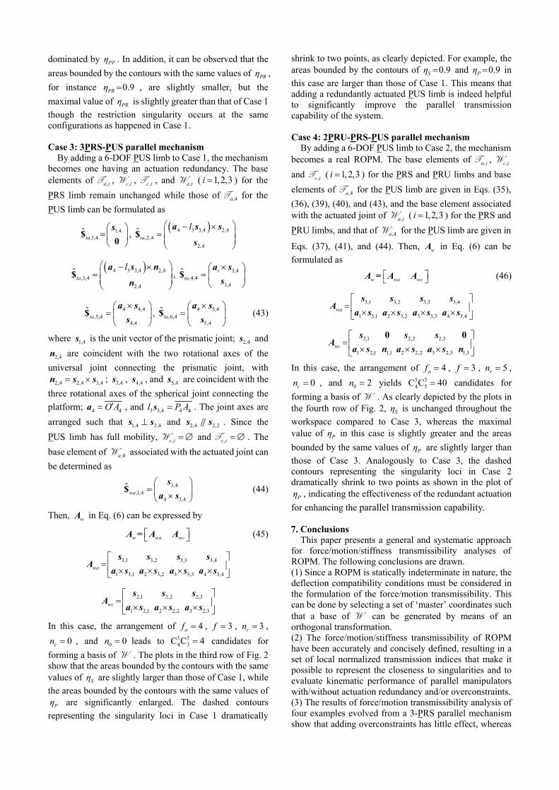
As for the two special cases given in Section 5, the criterion given in Eq. (34) can be split into two, one for identifying the permission singularity and the other for identifying the restriction singularity. Finally, a set of local normalized transmission indices are proposed and summarized in Table 1 for representing the closeness to singularities of parallel manipulators with or without actuation redundancy and/or overconstraints. Obviously, the larger a transmission index, the better the corresponding local kinematic performance.
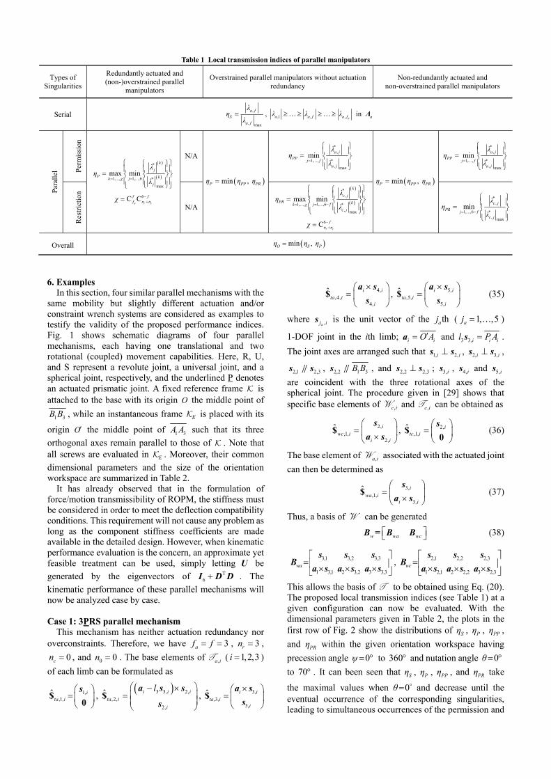
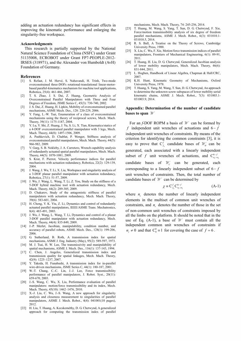
6. ExamplesIn this section, four similar parallel mechanisms with the
same mobility but slightly different actuation and/or constraint wrench systems are considered as examples to testify the validity of the proposed performance indices. Fig. 1 shows schematic diagrams of four parallel mechanisms, each having one translational and two rotational (coupled) movement capabilities. Here, R, U, and S represent a revolute joint, a universal joint, and a spherical joint, respectively, and the underlined P denotes an actuated prismatic joint. A fixed reference frame is attached to the base with its origin O the middle point of
1 3B B , while an instantaneous frame E is placed with its
origin O the middle point of 1 3A A such that its three
orthogonal axes remain parallel to those of . Note that all screws are evaluated in E . Moreover, their common
dimensional parameters and the size of the orientation workspace are summarized in Table 2.
It has already observed that in the formulation of force/motion transmissibility of ROPM, the stiffness must be considered in order to meet the deflection compatibility conditions. This requirement will not cause any problem as long as the component stiffness coefficients are made available in the detailed design. However, when kinematic performance evaluation is the concern, an approximate yet feasible treatment can be used, simply letting U be
generated by the eigenvectors of T6 I D D . The
kinematic performance of these parallel mechanisms will now be analyzed case by case.
Case 1: 3PRS parallel mechanism This mechanism has neither actuation redundancy nor
overconstraints. Therefore, we have 3af f , 3rn ,
0cn , and 0 0n . The base elements of ,a iT ( 1,2,3i )
of each limb can be formulated as
1,,1,
ˆ ita i
s$
0,
3 3, 2,
,2,
2,
ˆ i i i
ta i
i
l
a s s
s$ , 3,
,3,3,
ˆ i ita i
i
a s
s$
4,,4,
4,
ˆ i ita i
i
a s
s$ , 5,
,5,5,
ˆ i ita i
i
a s
s$ (35)
where ,aj is is the unit vector of the thaj ( 1, ,5aj )
1-DOF joint in the ith limb; i iO Aa and 3 3,i i il P As .
The joint axes are arranged such that 1, 2,i is s , 2, 3,i is s ,
2,1 2,3s s , 2,2 1 3B Bs , and 2,2 2,3s s ; 3,is , 4,is and 5,is
are coincident with the three rotational axes of the spherical joint. The procedure given in [29] shows that specific base elements of ,c iW and ,c iT can be obtained as
2,,1,
2,
ˆ iwc i
i i
s
a s$ , 2,
,1,ˆ i
tc i
s$
0 (36)
The base element of ,a iW associated with the actuated joint
can then be determined as
3,,1,
3,
ˆ iwa i
i i
s
a s$ (37)
Thus, a basis of W can be generated
w wa wc B B B= (38)
3,1 3,2 3,3
1 3,1 2 3,2 3 3,3wa
s s sB
a s a s a s, 2,1 2,2 2,3
1 2,1 2 2,2 3 2,3wc
s s sB
a s a s a s
This allows the basis of T to be obtained using Eq. (20). The proposed local transmission indices (see Table 1) at a given configuration can now be evaluated. With the dimensional parameters given in Table 2, the plots in the first row of Fig. 2 show the distributions of Sη , Pη , PPη ,
and PRη within the given orientation workspace having
precession angle 0ψ to 360 and nutation angle 0θ to 70 . It can been seen that Sη , Pη , PPη , and PRη take
the maximal values when 0θ and decrease until the eventual occurrence of the corresponding singularities, leading to simultaneous occurrences of the permission and
Table 1 Local transmission indices of parallel manipulators
Types of Singularities
Redundantly actuated and (non-)overstrained parallel
manipulators
Overstrained parallel manipulators without actuation redundancy
Non-redundantly actuated and non-overstrained parallel manipulators
Serial ,
, max
a f
S
a f
λη
λ , ,1 , , aa a f a fλ λ λ in aΛ
Par
alle
l Per
mis
sion
*
1, ,61, , *
max
max min
k
j
P kjk χj
λη
λ
6C Ca r c
f ff n nχ
N/A
min , P PP PRη η η
*,
1, , *, max
mina j
PP j fa j
λη
λ
min , P PP PRη η η
*,
1, , *, max
mina j
PP j fa j
λη
λ
Res
tric
tion
N/A
*,
1, ,61, , *, max
max min
k
c j
PR kj fk χc j
λη
λ
6Cr c
fn nχ
*,
1, ,6 *, max
minc j
PR j fc j
λη
λ
Overall min , O S Pη η η
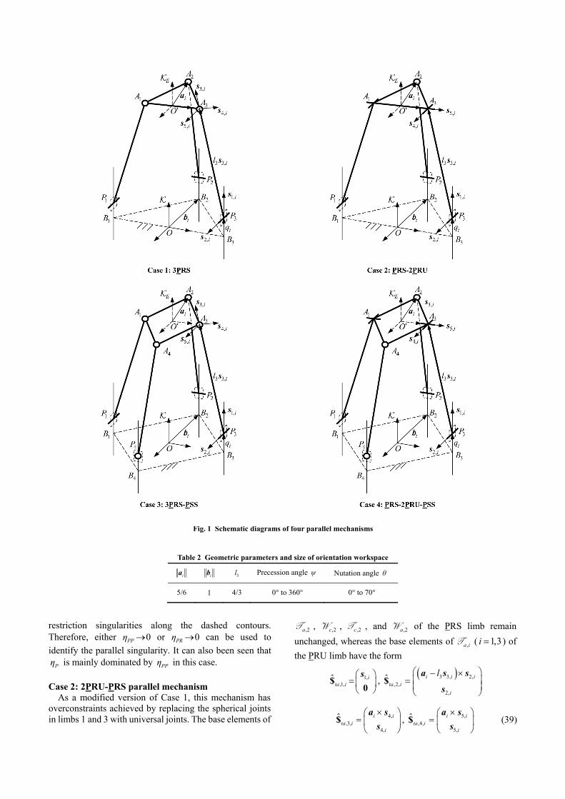
restriction singularities along the dashed contours. Therefore, either 0PPη or 0PRη can be used to
identify the parallel singularity. It can also been seen that
Pη is mainly dominated by PPη in this case.
Case 2: 2PRU-PRS parallel mechanism As a modified version of Case 1, this mechanism has
overconstraints achieved by replacing the spherical joints in limbs 1 and 3 with universal joints. The base elements of
,2aT , ,2cW , ,2cT , and ,2aW of the PRS limb remain
unchanged, whereas the base elements of ,a iT ( 1,3i ) of
the PRU limb have the form
1,,1,
ˆ ita i
s$
0,
3 3, 2,
,2,
2,
ˆ i i i
ta i
i
l
a s s
s$
4,,3,
4,
ˆ i ita i
i
a s
s$ , 5,
,4,5,
ˆ i ita i
i
a s
s$ (39)
Table 2 Geometric parameters and size of orientation workspace
ia ib 3l Precession angle ψ Nutation angle θ
5/6 1 4/3 0° to 360° 0° to 70°
Fig. 1 Schematic diagrams of four parallel mechanisms
where 4,is and 5,is are the unit vectors along the axes of
two 1-DOF revolute joints of the universal joint in the ith ( 1,3i ) limb, respectively, satisfying 4,i 2,is s , 4, 5,i is s ,
and 5,is is collinear with 1 3A A . Then, the specific base
elements of ,c iW and ,c iT ( 1,3i ) can be obtained as
2,,1,
2,
ˆ iwc i
i i
s
a s$ , ,2,
1,
ˆwc i
i
n
0$
2,,1,
ˆ itc i
s$
0, 1,
,2,1,
ˆ i itc i
i
a n
n$ (40)
where 1, 4, 5,i i i n s s . The base element of ,a iW ( 1,3i )
associated with the actuated joint can be determined as
3,,1,
3,
ˆ iwa i
i i
s
a s$ (41)
Thus, wA in Eq. (6) can be expressed as
w wa wc A A A= (42)
3,1 3,2 3,3
1 3,1 2 3,2 3 3,3wa
s s sA
a s a s a s
2,1 2,2 2,3
1 2,1 1,1 2 2,2 3 2,3 1,3wc
s s sA
a s n a s a s n
0 0
The arrangement of 3af f , 5rn , 0cn and
0 2n leads to 3 33 5C C 10 candidates for forming a basis
of W . With the same dimensional parameters, the plots in the second row of Fig. 2 achieved by exploring all the possible bases of W show that contours bounded by the same values of Sη and PPη remain the same throughout
the workspace as they are in Case 1, and Pη is mainly
Fig. 2 Distributions of performance indices within the given workspace cosx , siny θ ψ
dominated by PPη . In addition, it can be observed that the
areas bounded by the contours with the same values of PRη ,
for instance 0.9PRη , are slightly smaller, but the
maximal value of PRη is slightly greater than that of Case 1
though the restriction singularity occurs at the same configurations as happened in Case 1.
Case 3: 3PRS-PUS parallel mechanism By adding a 6-DOF PUS limb to Case 1, the mechanism
becomes one having an actuation redundancy. The base elements of ,a iT , ,c iW , ,c iT , and ,a iW ( 1,2,3i ) for the
PRS limb remain unchanged while those of ,4aT for the
PUS limb can be formulated as
1,4,1,4
ˆta
s$
0,
4 3 3,4 2,4
,2,4
2,4
ˆta
l
a s s
s$
4 3 3,4 2,4
,3,4
2,4
ˆta
l
a s n
n$ , 3,4
,4,43,4
ˆ ita
a s
s$
4 4,4,5,4
4,4
ˆta
a s
s$ , 4 5,4
,6,45,4
ˆta
a s
s$ (43)
where 1,4s is the unit vector of the prismatic joint; 2,4s and
2,4n are coincident with the two rotational axes of the
universal joint connecting the prismatic joint, with
2,4 2,4 3,4 n s s ; 3,4s , 4,4s , and 5,4s are coincident with the
three rotational axes of the spherical joint connecting the
platform; 4 4O Aa , and 3 3,4 4 4l P As . The joint axes are
arranged such that 1,4 2,4s s and 2,4 2,2s s . Since the
PUS limb has full mobility, ,c i W and ,c i T . The
base element of ,4aW associated with the actuated joint can
be determined as
3,4,1,4
4 3,4
ˆwa
s
a s$ (44)
Then, wA in Eq. (6) can be expressed by
w wa wc A A A= (45)
3,1 3,2 3,3 3,4
1 3,1 2 3,2 3 3,3 4 3,4wa
s s s sA
a s a s a s a s
2,1 2,2 2,3
1 2,1 2 2,2 3 2,3wc
s s sA
a s a s a s
In this case, the arrangement of 4af , 3f , 3rn ,
0cn , and 0 0n leads to 3 34 3C C 4 candidates for
forming a basis of W . The plots in the third row of Fig. 2 show that the areas bounded by the contours with the same values of Sη are slightly larger than those of Case 1, while
the areas bounded by the contours with the same values of
Pη are significantly enlarged. The dashed contours
representing the singularity loci in Case 1 dramatically
shrink to two points, as clearly depicted. For example, the areas bounded by the contours of 0.9Sη and 0.9Pη in
this case are larger than those of Case 1. This means that adding a redundantly actuated PUS limb is indeed helpful to significantly improve the parallel transmission capability of the system.
Case 4: 2PRU-PRS-PUS parallel mechanism By adding a 6-DOF PUS limb to Case 2, the mechanism
becomes a real ROPM. The base elements of ,a iT , ,c iW
and ,c iT ( 1,2,3i ) for the PRS and PRU limbs and base
elements of ,4aT for the PUS limb are given in Eqs. (35),
(36), (39), (40), and (43), and the base element associated with the actuated joint of ,a iW ( 1,2,3i ) for the PRS and
PRU limbs, and that of ,4aW for the PUS limb are given in
Eqs. (37), (41), and (44). Then, wA in Eq. (6) can be
formulated as
w wa wc A A A= (46)
3,1 3,2 3,3 3,4
1 3,1 2 3,2 3 3,3 4 3,4wa
s s s sA
a s a s a s a s
2,1 2,2 2,3
1 2,1 1,1 2 2,2 3 2,3 1,3wc
s s sA
a s n a s a s n
0 0
In this case, the arrangement of 4af , 3f , 5rn ,
0cn , and 0 2n yields 3 34 5C C 40 candidates for
forming a basis of W . As clearly depicted by the plots in the fourth row of Fig. 2, Sη is unchanged throughout the
workspace compared to Case 3, whereas the maximal value of Pη in this case is slightly greater and the areas
bounded by the same values of Pη are slightly larger than
those of Case 3. Analogously to Case 3, the dashed contours representing the singularity loci in Case 2 dramatically shrink to two points as shown in the plot of
Pη , indicating the effectiveness of the redundant actuation
for enhancing the parallel transmission capability.
7. ConclusionsThis paper presents a general and systematic approach
for force/motion/stiffness transmissibility analyses of ROPM. The following conclusions are drawn. (1) Since a ROPM is statically indeterminate in nature, the deflection compatibility conditions must be considered in the formulation of the force/motion transmissibility. This can be done by selecting a set of ‘master’ coordinates such that a base of W can be generated by means of an orthogonal transformation. (2) The force/motion/stiffness transmissibility of ROPM have been accurately and concisely defined, resulting in a set of local normalized transmission indices that make it possible to represent the closeness to singularities and to evaluate kinematic performance of parallel manipulators with/without actuation redundancy and/or overconstraints. (3) The results of force/motion transmissibility analysis of four examples evolved from a 3-PRS parallel mechanism show that adding overconstraints has little effect, whereas
adding an actuation redundancy has significant effects in improving the kinematic performance and enlarging the singularity-free workspace.
Acknowledgments This research is partially supported by the National
Natural Science Foundation of China (NSFC) under Grant 51135008, ECROBOT under Grant FP7-PEOPLE-2012- IRSES (318971), and the Alexander von Humboldt (AvH) Foundation of Germany.
References [1] S. Refaat, J. M. Hervé, S. Nahavandi, H. Trinh, Two-mode
overconstrained three-DOFs rotational-translational linear-motor- based parallel-kinematics mechanism for machine tool applications, Robotica, 25(4): 461-466, 2007.
[2] T. S. Zhao, J. S. Dai, Z. Huang, Geometric Analysis of Overconstrained Parallel Manipulators with Three and Four Degrees of Freedom, JSME Series C, 45(3): 730-740, 2002.
[3] J. S. Dai, Z. Huang, H. Lipkin, Mobility of overconstrained parallel mechanisms, ASME Mech. Des., 128: 220-229, 2006.
[4] Y. Fang, L.-W. Tsai, Enumeration of a class of overconstrained mechanisms using the theory of reciprocal screws, Mech. Mach. Theory, 39(11): 1175-1187, 2004.
[5] Y. Lu, Y. Shi, Z. Huang, J. Yu, S. Li, X. Tian, Kinematics/statics of a 4-DOF overconstrained parallel manipulator with 3 legs, Mech. Mach. Theory, 44(8): 1497-1506, 2009.
[6] A. Pashkevich, D. Chablat, P. Wenger, Stiffness analysis of overconstrained parallel manipulators, Mech. Mach. Theory, 44(5): 966-982, 2009.
[7] V. Garg, S. B. Nokleby, J. A. Carretero, Wrench capability analysis of redundantly actuated spatial parallel manipulators, Mech. Mach. Theory, 44(5): 1070-1081, 2009.
[8] S. Krut, F. Pierrot, Velocity performance indices for parallel mechanisms with actuation redundancy, Robotica, 22(2): 129-139, 2004.
[9] J. Wang, J. Wu, T. Li, X. Liu, Workspace and singularity analysis of a 3-DOF planar parallel manipulator with actuation redundancy, Robotica, 27(1): 51-57, 2009.
[10] J. Wu, J. Wang, L. Wang, T. Li, Z. You, Study on the stiffness of a 5-DOF hybrid machine tool with actuation redundancy, Mech. Mach. Theory, 44(2): 289-305, 2009.
[11] D. Chakarov, Study of the antagonistic stiffness of parallel manipulators with actuation redundancy, Mech. Mach. Theory, 39(6): 583-601, 2004.
[12] H. Cheng, Y. K. Yiu, Z. Li, Dynamics and control of redundantly actuated parallel manipulators, IEEE/ASME Trans. Mechatronics, 8(4): 483-491, 2003.
[13] J. Wu, J. Wang, L. Wang, T. Li, Dynamics and control of a planar 3-DOF parallel manipulator with actuation redundancy, Mech. Mach. Theory, 44(4): 835-849, 2009.
[14] J.-P. Merlet, Jacobian, manipulability, condition number, and accuracy of parallel robots, ASME Mech. Des., 128(1): 199-206, 2006.
[15] G. Sutherland, B. Roth, A transmission index for spatial mechanisms, ASME J. Eng. Industry (May), 95(2): 589-597, 1973.
[16] M. J. Tsai, H. W. Lee, The transmissivity and manipulability of spatial mechanisms, ASME J. Mech. Des., 116(1): 137-143, 1994.
[17] C. Chen, J. Angeles, Generalized transmission index and transmission quality for spatial linkages, Mech. Mach. Theory, 42(9): 1225–1237, 2007.
[18] Y. Takeda, H. Funabashi, A transmission index for in-parallel wire-driven mechanisms, JSME Series C, 44(1): 180-187, 2001.
[19] W.-T. Chang, C.-C. Lin, J.-J. Lee, Force transmissibility performance of parallel manipulators, J. Robot. Syst., 20(11): 659-670, 2003.
[20] J.-S. Wang, C. Wu, X. Liu, Performance evaluation of parallel manipulators: motion/force transmissibility and its index, Mech. Mach. Theory, 45(10): 1462–1476, 2010.
[21] X.-J. Liu, C. Wu, J.-S. Wang, A new approach for singularity analysis and closeness measurement to singularities of parallel manipulators, ASME J. Mech. Robot., 4(4): 041001(10 pages), 2012.
[22] H. Liu, T. Huang, A. Kecskeméthy, D. G. Chetwynd, A generalized approach for computing the transmission index of parallel
mechanisms, Mech. Mach. Theory, 74: 245-256, 2014. [23] T. Huang, M. Wang, S. Yang, T. Sun, D. G. Chetwynd, F. Xie,
Force/motion transmissibility analysis of six degree of freedom parallel mechanisms, ASME J. Mech. Robot., 6(3): 031010.1- 031010.5, 2014.
[24] R. S. Ball, A Treatise on the Theory of Screws, Cambridge University Press, 1900.
[25] X. Liu, C. Wu, F. Xie, Motion/force transmission indices of parallel manipulators, Frontiers of Mechanical Engineering, 6(1): 89-91, 2011.
[26] T. Huang, H. Liu, D. G. Chetwynd, Generalized Jacobian analysis of lower mobility manipulators, Mech. Mach. Theory, 46(6): 831-844, 2011.
[27] L. Hogben, Handbook of Linear Algebra, Chapman & Hall/CRC, 2007.
[28] K.H. Hunt, Kinematic Geometry of Mechanisms, Oxford University Press, 1978.
[29] T. Huang, S. Yang, M. Wang, T. Sun, D. G. Chetwynd, An approach to determine the unknown screw subspaces of lower mobility serial kinematic chains, ASME J. Mech. Robot., 7(3): 031003.1- 031003.9, 2014.
Appendix: Determination of the number of candidate bases to span W
For an f-DOF ROPM a basis of W can be formed by f independent unit wrenches of actuations and 6 f
independent unit wrenches of constraints. By means of the criterion for identifying the common constraints [3], it is easy to prove that C
a
ff candidate bases of aW can be
generated, each associated with a linearly independent subset of f unit wrenches of actuations, and 6C
r c
fn n
candidate bases of cW can be generated, each
corresponding to a linearly independent subset of 6 f
unit wrenches of constraints. Then, the total number of candidate bases of W can be determined by
6C Ca r c
f ff n nχ
(A-1)
where cn denotes the number of linearly independent
elements in the multiset of common unit wrenches of constraints, and rn denotes the number of those in the set
of non-common unit wrenches of constraints imposed by all the limbs on the platform. It should be noted that in the use of Eq. (A-1), a base of W must contain all the independent common unit wrenches of constraints if
0cn and that 00C 1 for covering the case of 6f .