for workpiece measurement - absolute machine...
TRANSCRIPT
FanucUser’s Manual
Touch Probe Cycles
for Workpiece Measurement
NC Software
0, 0i, 16, 18, 21, 30, 31, 32
English (en)
02/2014
Contents
2 Fanuc | User’s Manual Touch Probe Cycles for Fanuc NC Software | 02/2014
Contents
1 Fundamentals....................................................................................................................................15
2 Touch Probe Cycles: Automatically Measuring Workpieces.........................................................23
3 Touch Probe Cycles: Automatically Measuring Workpieces.........................................................37
4 Programming examples...................................................................................................................63
5 Special cycles....................................................................................................................................71
6 Calibrating a Touch Trigger Probe.................................................................................................. 77
7 Parameter tables...............................................................................................................................85
8 Software installation........................................................................................................................93
9 Fanuc GUI Installation................................................................................................................... 123
10 Error messages............................................................................................................................... 133

Fanuc | User’s Manual Touch Probe Cycles for Fanuc NC Software | 02/2014 3
Contents
4 Fanuc | User’s Manual Touch Probe Cycles for Fanuc NC Software | 02/2014
1 Fundamentals....................................................................................................................................15
1.1 Important notes......................................................................................................................................16
1.2 About this manual................................................................................................................................. 17
1.3 Fundamental software information......................................................................................................18
Program overview.................................................................................................................................... 18
Installation information............................................................................................................................. 19
1.4 Fundamentals of touch probe cycles...................................................................................................20
Available touch probe cycles....................................................................................................................20
Possibilities of use for touch probe cycles.............................................................................................. 20
1.5 Fundamentals of Correct Measuring....................................................................................................21
Fanuc | User’s Manual Touch Probe Cycles for Fanuc NC Software | 02/2014 5
2 Touch Probe Cycles: Automatically Measuring Workpieces.........................................................23
2.1 Fundamentals of automatic datum setting.........................................................................................24
2.2 Datum Setting in any axis.................................................................................................................... 25
2.3 Datum Setting a corner in two axes................................................................................................... 26
2.4 Datum Setting a corner in three axes................................................................................................. 27
2.5 Setting datum in the center of a bore hole (4 measured points)..................................................... 28
2.6 Setting datum in the center of a bore hole (3 measured points)..................................................... 29
2.7 Setting datum in the center of a stud (4 measured points)..............................................................31
2.8 Setting datum in the center of a stud (3 measured points)..............................................................32
2.9 Setting datum in the center of a slot..................................................................................................34
2.10 Setting datum in the center of a ridge................................................................................................35
2.11 Setting datum in the center of a bore hole or center of a slot, each with obstacle........................36
Contents
6 Fanuc | User’s Manual Touch Probe Cycles for Fanuc NC Software | 02/2014
3 Touch Probe Cycles: Automatically Measuring Workpieces.........................................................37
3.1 Fundamentals of automatic measuring...............................................................................................38
3.2 Measuring a Single Point in any Axis..................................................................................................40
3.3 Measuring a Corner in Two Axes......................................................................................................... 41
3.4 Measuring a Corner in Three Axes...................................................................................................... 43
3.5 Measuring a Bore Hole (4 Measured Points).......................................................................................45
3.6 Measuring a Bore Hole (3 Measured Points).......................................................................................47
3.7 Measuring a Stud (Outside Diameter, 4 Measured Points)................................................................49
3.8 Measuring a Stud (Outside Diameter, 3 Measured Points)................................................................51
3.9 Measuring a Slot....................................................................................................................................53
3.10 Measuring a Ridge................................................................................................................................. 55
3.11 Measuring Bore Hole or Slot, Each with Obstacle.............................................................................57
3.12 Measuring angle or distance................................................................................................................ 59
Measuring distance..................................................................................................................................60
Measuring angle.......................................................................................................................................61
Fanuc | User’s Manual Touch Probe Cycles for Fanuc NC Software | 02/2014 7
4 Programming examples...................................................................................................................63
4.1 Measuring sample components........................................................................................................... 64
Measuring a sample component (part 1).................................................................................................65
Measuring a sample component (part 2).................................................................................................66
Measuring a sample component (part 3).................................................................................................67
4.2 Distances on sample components....................................................................................................... 68
4.3 Measuring angles on sample components......................................................................................... 69
4.4 Testing tolerances.................................................................................................................................. 70
Contents
8 Fanuc | User’s Manual Touch Probe Cycles for Fanuc NC Software | 02/2014
5 Special cycles....................................................................................................................................71
5.1 Program 09703 PROTECTED MOVE: Protected move........................................................................ 72
5.2 Function G68: Measuring in a Rotated Coordinate System.............................................................. 73
5.3 Test component presence..................................................................................................................... 75
Fanuc | User’s Manual Touch Probe Cycles for Fanuc NC Software | 02/2014 9
6 Calibrating a Touch Trigger Probe.................................................................................................. 77
6.1 Calibrating a touch trigger probe.........................................................................................................78
Why calibrate?..........................................................................................................................................78
When to calibrate.....................................................................................................................................78
How to calibrate.......................................................................................................................................78
6.2 Measuring touch probe length with the ring gauge.......................................................................... 80
6.3 Measuring touch probe radius and center misalignment with the ring gauge................................81
6.4 Measuring touch probe radius and center misalignment with the calibration sphere................... 83
Contents
10 Fanuc | User’s Manual Touch Probe Cycles for Fanuc NC Software | 02/2014
7 Parameter tables...............................................................................................................................85
7.1 Call parameters...................................................................................................................................... 86
7.2 Result parameters.................................................................................................................................. 88
7.3 Calculating and result parameters Function D................................................................................... 89
7.4 Calibrating parameters.......................................................................................................................... 90
7.5 Internal parameters................................................................................................................................91
Fanuc | User’s Manual Touch Probe Cycles for Fanuc NC Software | 02/2014 11
8 Software installation........................................................................................................................93
8.1 Software installation..............................................................................................................................94
Program overview.................................................................................................................................... 94
Requirements for installation................................................................................................................... 94
Installing and testing software.................................................................................................................95
8.2 Program O9710 USERPARATAB: Setting parameters......................................................................... 96
Program O9710 USERPARATAB: Setting parameters..............................................................................96
Program O9706 SET WCS: Parameters #1 to #4..................................................................................103
Program O9706 SET TOOL: Parameters #5 to #8.................................................................................105
Oriented spindle stop.............................................................................................................................107
8.3 Program O9708 PROBE ON/OFF: Switching the touch probe on/off............................................. 108
Switching the touch probe on and off................................................................................................... 108
Program O9708 PROBE ON/OFF LEVEL...............................................................................................108
Program O9708 PROBE ON/OFF TS444...............................................................................................109
Program O9708 PROBE ON/OFF PULSE.............................................................................................. 111
Function clean measuring position........................................................................................................ 111
8.4 Program O9711 MESSAGES: Error output........................................................................................ 112
8.5 Program O9716 DPRNT: Data output.................................................................................................114
8.6 Modifying machine parameters..........................................................................................................115
8.7 Switching Units of Measurement (metric / inch)............................................................................. 119
8.8 Checking validity of the trigger..........................................................................................................120
Validity of Checking the trigger..............................................................................................................120
Autostart modefor touch probes with infrared transmission.................................................................120
8.9 Addresses of available inputs and outputs.......................................................................................121
Contents
12 Fanuc | User’s Manual Touch Probe Cycles for Fanuc NC Software | 02/2014
9 Fanuc GUI Installation................................................................................................................... 123
9.1 Fanuc GUI installation......................................................................................................................... 124
Fundamentals......................................................................................................................................... 124
Requirements for installation................................................................................................................. 124
Data backup............................................................................................................................................124
Installing data on the control................................................................................................................. 127
Modifying system parameters............................................................................................................... 130
9.2 Operating the graphical user interface.............................................................................................. 131
Selecting measurement cycles..............................................................................................................131
Entering parameters for measurement cycles...................................................................................... 132
Fanuc | User’s Manual Touch Probe Cycles for Fanuc NC Software | 02/2014 13
10 Error messages............................................................................................................................... 133
10.1 Error messages..................................................................................................................................... 134
10.2 Advanced error diagnosis....................................................................................................................136

1Fundamentals
Fundamentals 1.1 Important notes
1
16 Fanuc | User’s Manual Touch Probe Cycles for Fanuc NC Software | 02/2014
1.1 Important notes
Please read the programming instructions carefully and then
commission the touch probe and cycles.
The content of the data carrier and corresponding documentation
(summarized as "data") are protected by copyright. DR. JOHANNES
HEIDENHAIN GmbH retains all rights to the data or individual
parts thereof, in particular the right to copy, lease, modify, store
and process in CNC controls or other electronic systems (e.g.
PCs). Distribution as well as duplication of the data, or use of the
programs in more than one control is prohibited without the explicit
permission of DR. JOHANNES HEIDENHAIN GMBH.
Violation obligates compensation for damages.
All data has been carefully tested. Nevertheless, no warranty can
be assumed with respect to completeness and freedom from
errors.
The measurement cycles should be interpreted as examples for
solving measurement tasks and must be adapted by machine
manufacturers or users to the specific type of machine. Before
commissioning, determine whether the parameters used by
the measurement cycles are already being used. If this is the
case these cycles must be adapted, as the overwriting of used
parameters may cause unforeseeable damage to the machine.
When commissioning the measurement cycles the program must
be tested blockwise under observance of all safety measures
(especially block testing prior to execution, single block and
reduced feed rate). After completion of commissioning, parameters
used and executed machine-specific program adaptations must be
documented.
Furthermore, DR. JOHANNES HEIDENHAIN GmbH is excluded
from any liability inasmuch, for example, as it is not patently
responsible according to product liability law, due to intent, gross
negligence, due to bodily harm or harm to health, due to the
assumption of a guarantee for specific characteristics, due to
fraudulent concealment of a defect or due to the violation of
essential contractual obligations. Compensation for violation of
fundamental contractual obligations, however, is limited to typically
foreseeable damage, inasmuch as no intent or gross negligence
is involved. Specified legal disclaimers are deemed as accepted
following the installing of measurement cycles at the latest.
We reserve the right to technical modifications for product
improvements. Our General Sales Conditions apply.
© 2013 DR. JOHANNES HEIDENHAIN GmbH
About this manual 1.2
1
Fanuc | User’s Manual Touch Probe Cycles for Fanuc NC Software | 02/2014 17
1.2 About this manual
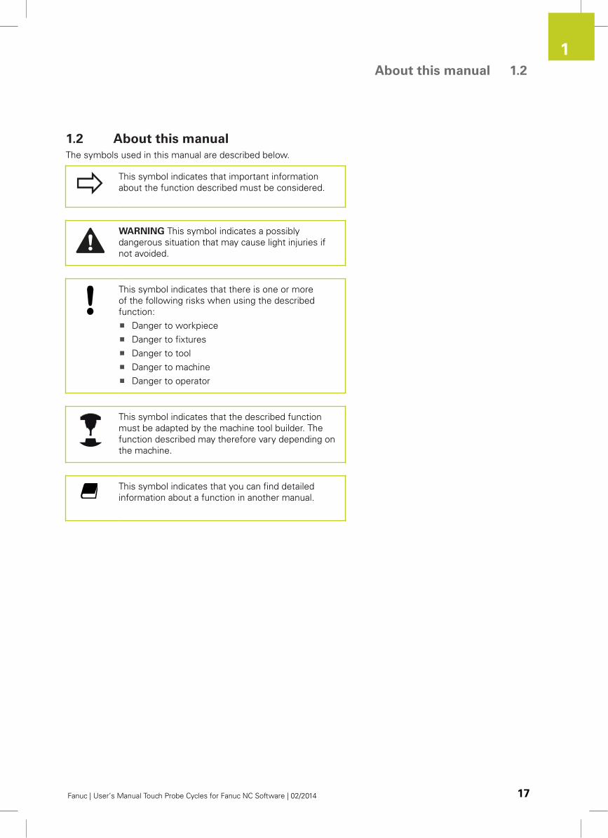
The symbols used in this manual are described below.
This symbol indicates that important information
about the function described must be considered.
WARNING This symbol indicates a possibly
dangerous situation that may cause light injuries if
not avoided.
This symbol indicates that there is one or more
of the following risks when using the described
function:
Danger to workpiece
Danger to fixtures
Danger to tool
Danger to machine
Danger to operator
This symbol indicates that the described function
must be adapted by the machine tool builder. The
function described may therefore vary depending on
the machine.
This symbol indicates that you can find detailed
information about a function in another manual.
Fundamentals 1.3 Fundamental software information
1
18 Fanuc | User’s Manual Touch Probe Cycles for Fanuc NC Software | 02/2014
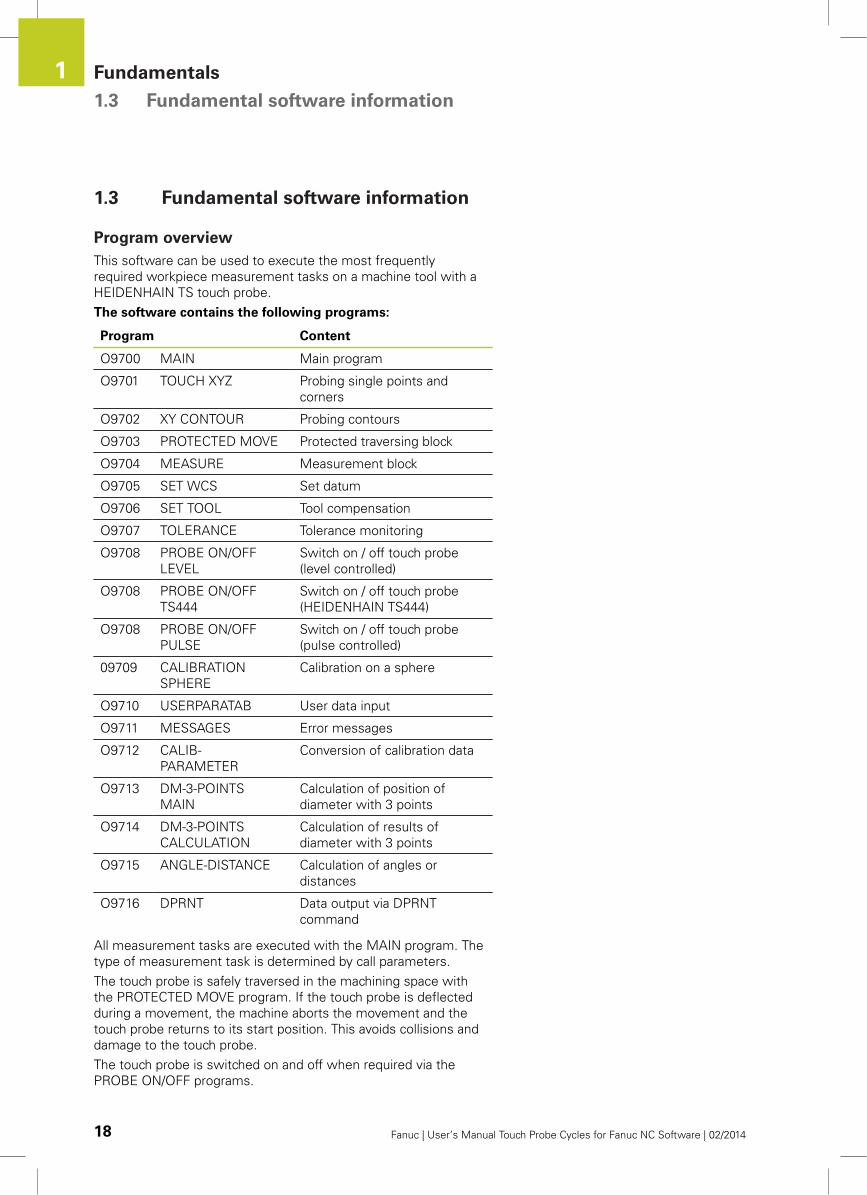
1.3 Fundamental software information
Program overview
This software can be used to execute the most frequently
required workpiece measurement tasks on a machine tool with a
HEIDENHAIN TS touch probe.
The software contains the following programs:
Program Content
O9700 MAIN Main program
O9701 TOUCH XYZ Probing single points and
corners
O9702 XY CONTOUR Probing contours
O9703 PROTECTED MOVE Protected traversing block
O9704 MEASURE Measurement block
O9705 SET WCS Set datum
O9706 SET TOOL Tool compensation
O9707 TOLERANCE Tolerance monitoring
O9708 PROBE ON/OFF
LEVEL
Switch on / off touch probe
(level controlled)
O9708 PROBE ON/OFF
TS444
Switch on / off touch probe
(HEIDENHAIN TS444)
O9708 PROBE ON/OFF
PULSE
Switch on / off touch probe
(pulse controlled)
09709 CALIBRATION
SPHERE
Calibration on a sphere
O9710 USERPARATAB User data input
O9711 MESSAGES Error messages
O9712 CALIB-
PARAMETER
Conversion of calibration data
O9713 DM-3-POINTS
MAIN
Calculation of position of
diameter with 3 points
O9714 DM-3-POINTS
CALCULATION
Calculation of results of
diameter with 3 points
O9715 ANGLE-DISTANCE Calculation of angles or
distances
O9716 DPRNT Data output via DPRNT
command
All measurement tasks are executed with the MAIN program. The
type of measurement task is determined by call parameters.
The touch probe is safely traversed in the machining space with
the PROTECTED MOVE program. If the touch probe is deflected
during a movement, the machine aborts the movement and the
touch probe returns to its start position. This avoids collisions and
damage to the touch probe.
The touch probe is switched on and off when required via the
PROBE ON/OFF programs.
Fundamental software information 1.3
1
Fanuc | User’s Manual Touch Probe Cycles for Fanuc NC Software | 02/2014 19
The software parameters are defined in the USERPARATAB
program.
All further programs are support programs used internally by the
software.
Installation information
Before working with the touch probe cycles you must carry out the
following:
Requirement for installation
See "Software installation", page 94
Mechanical installation
see the installation instructions of the
HEIDENHAIN touch probe used
Software installation
Installing the software: page 94
Set parameters in the 09710 USERPARATAB
program: page 96
Set parameters in the 09708 PROBE ON/OFF
program: page 111
Calibrating the touch probe
See "Calibrating a touch trigger probe",
page 78
Fundamentals 1.4 Fundamentals of touch probe cycles
1
20 Fanuc | User’s Manual Touch Probe Cycles for Fanuc NC Software | 02/2014
1.4 Fundamentals of touch probe cycles
Available touch probe cycles
Touch probe cycles are available for the following tasks:
Calibrating TS touch probes
See page 78
Automatically measuring workpieces
See page 24
Automatically measuring workpieces
See page 38
Special cycles
5.1 "Program 09703 PROTECTED MOVE:
Protected move", page 72
5.3 "Test component presence", page 75
5.2 "Function G68: Measuring in a Rotated
Coordinate System", page 73
Possibilities of use for touch probe cycles
Possible measuring tasks
Single probing in any axis (X/Y/Z)
Corner in two axes
Corner in three axes
Slot
Ridge
Inside diameter
Outside diameter
Distance measurement
Angle measurement
Possible measurement results
Determine workpiece position in an active WCS
Set datum
Test tolerances
Correct tool data
Determine distances and angles
Fundamentals of Correct Measuring 1.5
1
Fanuc | User’s Manual Touch Probe Cycles for Fanuc NC Software | 02/2014 21
1.5 Fundamentals of Correct Measuring
Measurement cycles should be interpreted as
examples for solving measurement tasks and must
be adapted by machine manufacturers or users to
the specific type of machine.
When commissioning the measurement cycles
the program must be tested blockwise under
observance of all safety measures (block testing prior
to execution, single block and reduced feed rate).
For safe, correct measurements:
Traverse the measurement position to a protected
traversing block (See page 72).
Use the same speed for measuring and
calibrating.
Observe the acceleration/brake ramp of the
machine.
Specify the (safety) clearance accordingly.
The machine must not be in the acceleration/
brake ramp during probing.
Firmly clamp the measurement object.
Specify the measurement position so that the
probed face is only reached with the probe tip.
Enter parameters with a point "." ("1." corresponds
to 1mm, "1" corresponds to 1 µm).

2Touch Probe
Cycles:Automatically
MeasuringWorkpieces
Touch Probe Cycles: Automatically Measuring Workpieces 2.1 Fundamentals of automatic datum setting
2
24 Fanuc | User’s Manual Touch Probe Cycles for Fanuc NC Software | 02/2014
2.1 Fundamentals of automatic datum
setting
This chapter specifies the functions for setting a datum on a newly
clamped workpiece.
Pre-positioning the touch probe is carried out either with the
handwheel or with the axis direction keys. You can alternatively pre-
position the touch probe with a "protected traversing block" (See
page 72).
Use the O9700 MAIN program to call all measurement functions.
Configuration of the parameters determines the method of datum
measurement.
The software supports the following processes:
Function Page
Datum Setting in any axis page 25
Datum Setting a corner in two axes page 26
Datum Setting a corner in three axes page 27
Setting datum in the center of a slot page 34
Setting datum in the center of a ridge page 35
Setting datum in the center of a bore hole (4
measured points)
page 28
Setting datum in the center of a bore hole (3
measured points)
page 29
Setting datum in the center of a stud (4 measured
points)
page 31
Setting datum in the center of a stud (3 measured
points)
page 32
Setting datum in the center of a bore hole or
center of a slot, each with obstacle
page 36
Observe that the function G68 (coordinate
rotation) is inactive during the execution of
probing cycles.
Detailed descriptions of optional parameters: See
"Call parameters", page 86.
Datum Setting in any axis 2.2
2
Fanuc | User’s Manual Touch Probe Cycles for Fanuc NC Software | 02/2014 25
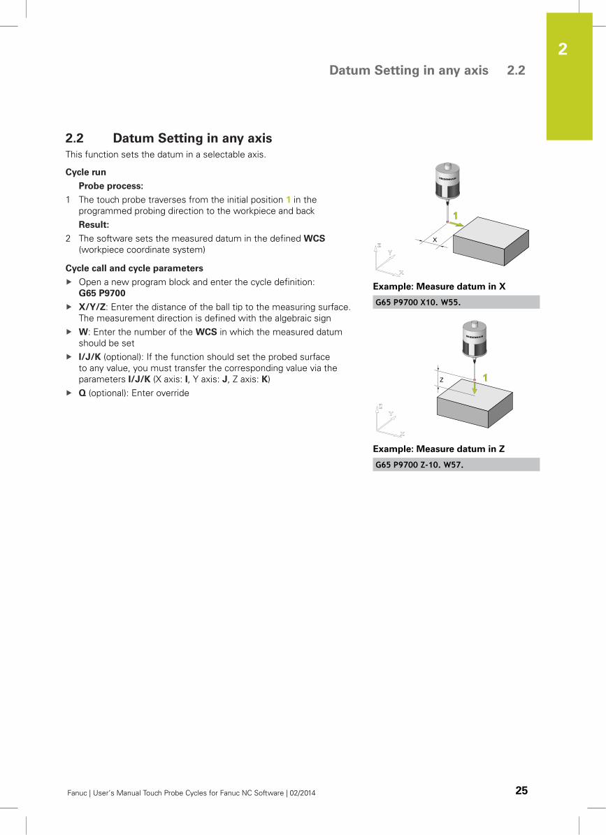
2.2 Datum Setting in any axis
This function sets the datum in a selectable axis.
Cycle run
Probe process:
1 The touch probe traverses from the initial position 1 in the
programmed probing direction to the workpiece and back
Result:
2 The software sets the measured datum in the defined WCS
(workpiece coordinate system)
Cycle call and cycle parameters
Open a new program block and enter the cycle definition:
G65 P9700
X/Y/Z: Enter the distance of the ball tip to the measuring surface.
The measurement direction is defined with the algebraic sign
W: Enter the number of the WCS in which the measured datum
should be set
I/J/K (optional): If the function should set the probed surface
to any value, you must transfer the corresponding value via the
parameters I/J/K (X axis: I, Y axis: J, Z axis: K)
Q (optional): Enter override
Example: Measure datum in X
G65 P9700 X10. W55.
Example: Measure datum in Z
G65 P9700 Z-10. W57.
Touch Probe Cycles: Automatically Measuring Workpieces 2.3 Datum Setting a corner in two axes
2
26 Fanuc | User’s Manual Touch Probe Cycles for Fanuc NC Software | 02/2014
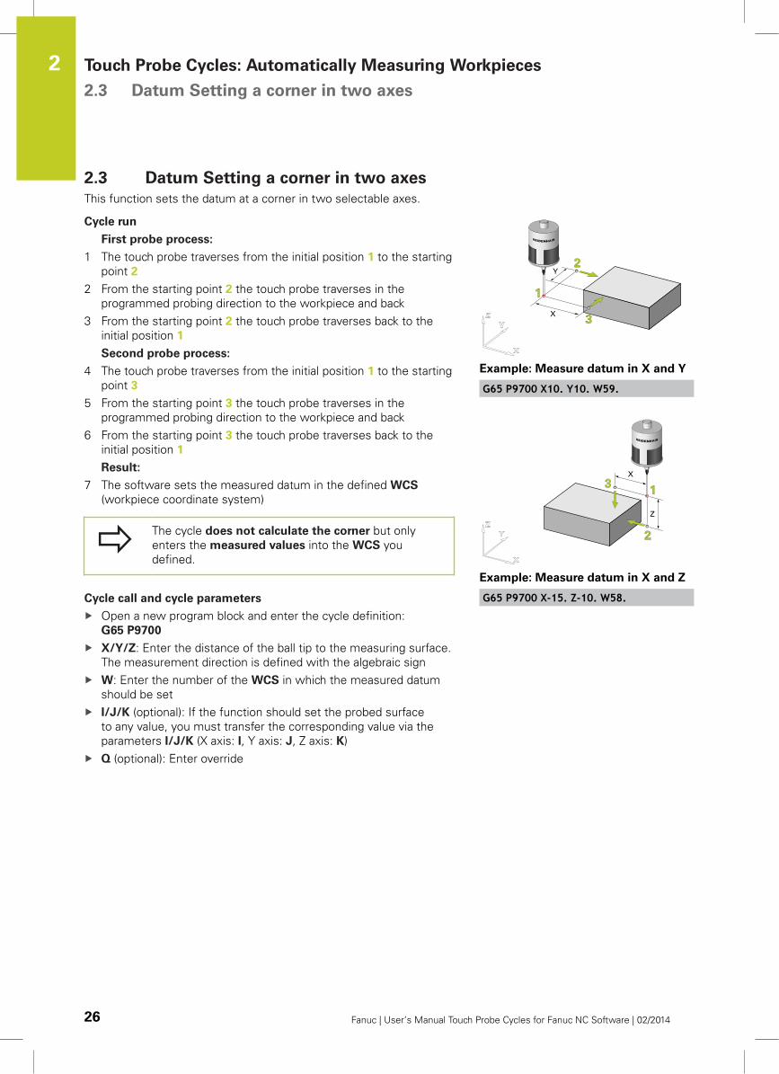
2.3 Datum Setting a corner in two axes
This function sets the datum at a corner in two selectable axes.
Cycle run
First probe process:
1 The touch probe traverses from the initial position 1 to the starting
point 2
2 From the starting point 2 the touch probe traverses in the
programmed probing direction to the workpiece and back
3 From the starting point 2 the touch probe traverses back to the
initial position 1
Second probe process:
4 The touch probe traverses from the initial position 1 to the starting
point 3
5 From the starting point 3 the touch probe traverses in the
programmed probing direction to the workpiece and back
6 From the starting point 3 the touch probe traverses back to the
initial position 1
Result:
7 The software sets the measured datum in the defined WCS
(workpiece coordinate system)
The cycle does not calculate the corner but only
enters the measured values into the WCS you
defined.
Cycle call and cycle parameters
Open a new program block and enter the cycle definition:
G65 P9700
X/Y/Z: Enter the distance of the ball tip to the measuring surface.
The measurement direction is defined with the algebraic sign
W: Enter the number of the WCS in which the measured datum
should be set
I/J/K (optional): If the function should set the probed surface
to any value, you must transfer the corresponding value via the
parameters I/J/K (X axis: I, Y axis: J, Z axis: K)
Q (optional): Enter override
Example: Measure datum in X and Y
G65 P9700 X10. Y10. W59.
Example: Measure datum in X and Z
G65 P9700 X-15. Z-10. W58.
Datum Setting a corner in three axes 2.4
2
Fanuc | User’s Manual Touch Probe Cycles for Fanuc NC Software | 02/2014 27
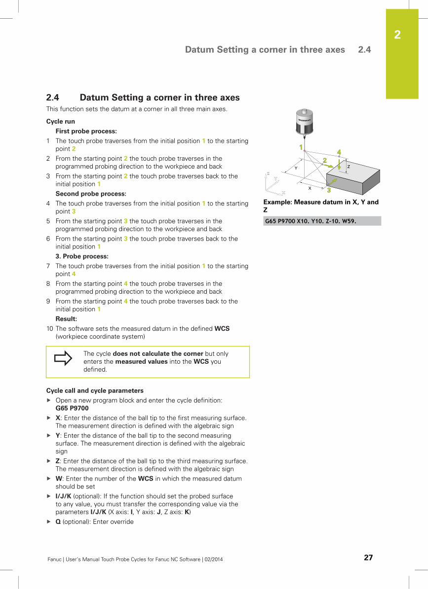
2.4 Datum Setting a corner in three axes
This function sets the datum at a corner in all three main axes.
Cycle run
First probe process:
1 The touch probe traverses from the initial position 1 to the starting
point 2
2 From the starting point 2 the touch probe traverses in the
programmed probing direction to the workpiece and back
3 From the starting point 2 the touch probe traverses back to the
initial position 1
Second probe process:
4 The touch probe traverses from the initial position 1 to the starting
point 3
5 From the starting point 3 the touch probe traverses in the
programmed probing direction to the workpiece and back
6 From the starting point 3 the touch probe traverses back to the
initial position 1
3. Probe process:
7 The touch probe traverses from the initial position 1 to the starting
point 4
8 From the starting point 4 the touch probe traverses in the
programmed probing direction to the workpiece and back
9 From the starting point 4 the touch probe traverses back to the
initial position 1
Result:
10 The software sets the measured datum in the defined WCS
(workpiece coordinate system)
The cycle does not calculate the corner but only
enters the measured values into the WCS you
defined.
Cycle call and cycle parameters
Open a new program block and enter the cycle definition:
G65 P9700
X: Enter the distance of the ball tip to the first measuring surface.
The measurement direction is defined with the algebraic sign
Y: Enter the distance of the ball tip to the second measuring
surface. The measurement direction is defined with the algebraic
sign
Z: Enter the distance of the ball tip to the third measuring surface.
The measurement direction is defined with the algebraic sign
W: Enter the number of the WCS in which the measured datum
should be set
I/J/K (optional): If the function should set the probed surface
to any value, you must transfer the corresponding value via the
parameters I/J/K (X axis: I, Y axis: J, Z axis: K)
Q (optional): Enter override
Example: Measure datum in X, Y and
Z
G65 P9700 X10. Y10. Z-10. W59.
Touch Probe Cycles: Automatically Measuring Workpieces 2.5 Setting datum in the center of a bore hole (4 measured points)
2
28 Fanuc | User’s Manual Touch Probe Cycles for Fanuc NC Software | 02/2014
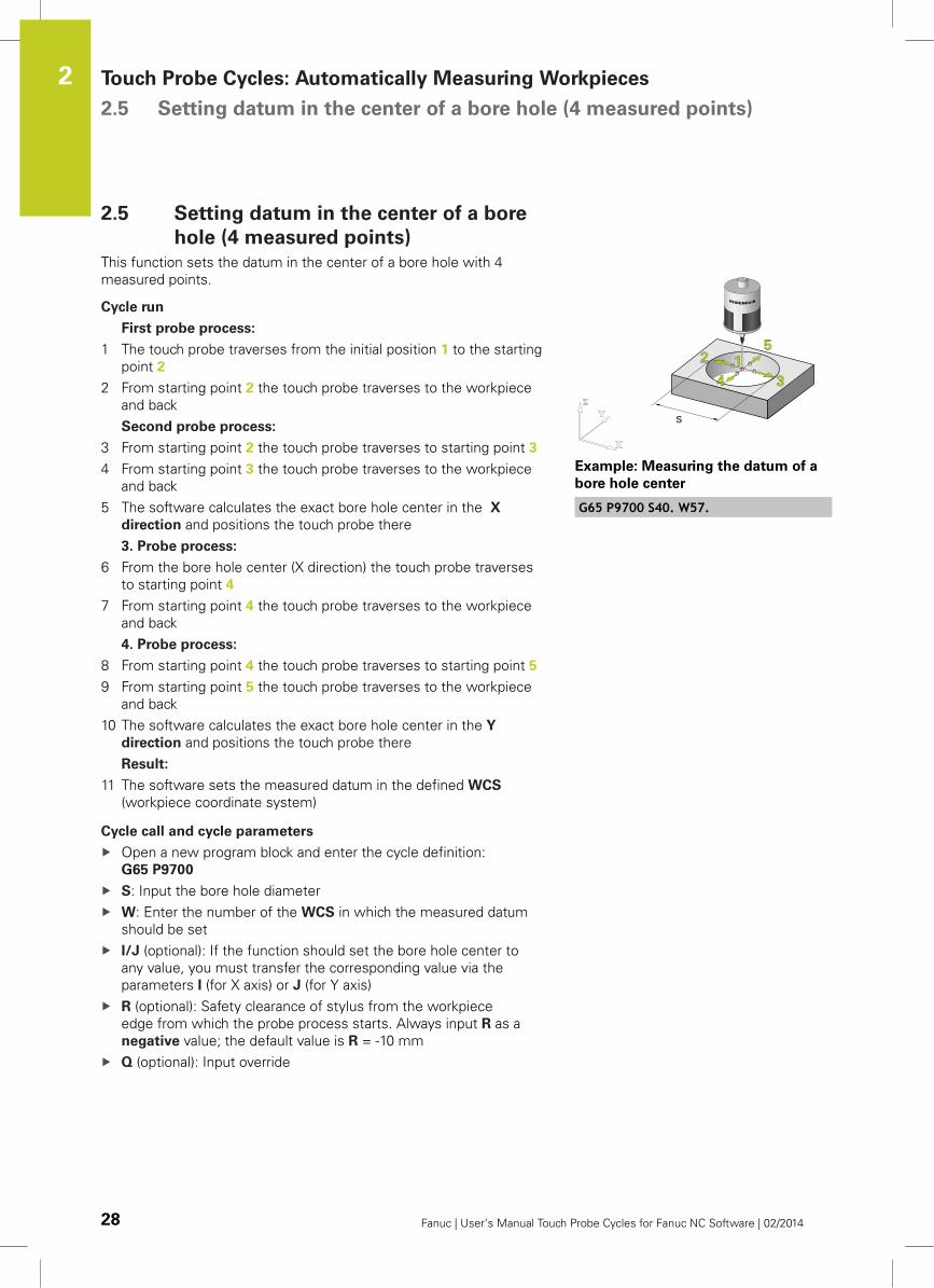
2.5 Setting datum in the center of a bore
hole (4 measured points)
This function sets the datum in the center of a bore hole with 4
measured points.
Cycle run
First probe process:
1 The touch probe traverses from the initial position 1 to the starting
point 2
2 From starting point 2 the touch probe traverses to the workpiece
and back
Second probe process:
3 From starting point 2 the touch probe traverses to starting point 3
4 From starting point 3 the touch probe traverses to the workpiece
and back
5 The software calculates the exact bore hole center in the X
direction and positions the touch probe there
3. Probe process:
6 From the bore hole center (X direction) the touch probe traverses
to starting point 4
7 From starting point 4 the touch probe traverses to the workpiece
and back
4. Probe process:
8 From starting point 4 the touch probe traverses to starting point 5
9 From starting point 5 the touch probe traverses to the workpiece
and back
10 The software calculates the exact bore hole center in the Y
direction and positions the touch probe there
Result:
11 The software sets the measured datum in the defined WCS
(workpiece coordinate system)
Cycle call and cycle parameters
Open a new program block and enter the cycle definition:
G65 P9700
S: Input the bore hole diameter
W: Enter the number of the WCS in which the measured datum
should be set
I/J (optional): If the function should set the bore hole center to
any value, you must transfer the corresponding value via the
parameters I (for X axis) or J (for Y axis)
R (optional): Safety clearance of stylus from the workpiece
edge from which the probe process starts. Always input R as a
negative value; the default value is R = -10 mm
Q (optional): Input override
Example: Measuring the datum of a
bore hole center
G65 P9700 S40. W57.
Setting datum in the center of a bore hole (3 measured points) 2.6
2
Fanuc | User’s Manual Touch Probe Cycles for Fanuc NC Software | 02/2014 29
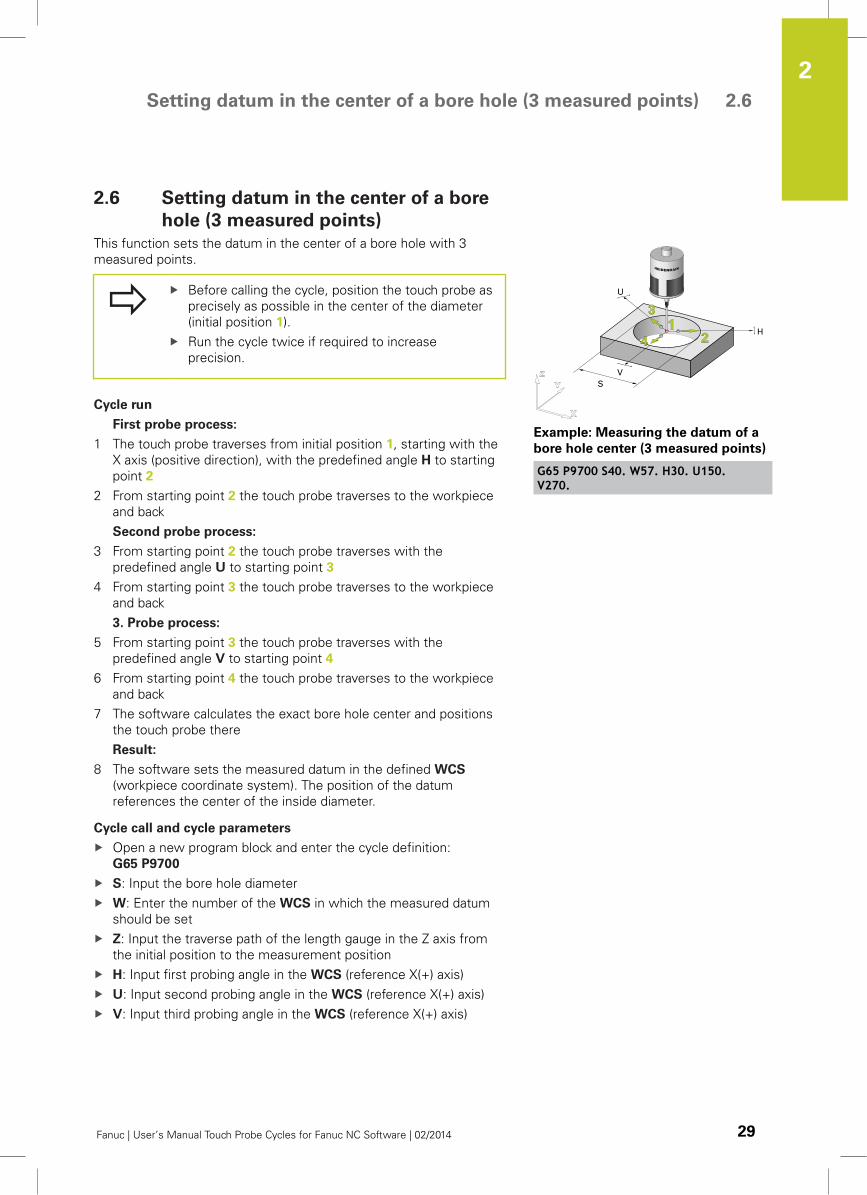
2.6 Setting datum in the center of a bore
hole (3 measured points)
This function sets the datum in the center of a bore hole with 3
measured points.
Before calling the cycle, position the touch probe as
precisely as possible in the center of the diameter
(initial position 1).
Run the cycle twice if required to increase
precision.
Cycle run
First probe process:
1 The touch probe traverses from initial position 1, starting with the
X axis (positive direction), with the predefined angle H to starting
point 2
2 From starting point 2 the touch probe traverses to the workpiece
and back
Second probe process:
3 From starting point 2 the touch probe traverses with the
predefined angle U to starting point 3
4 From starting point 3 the touch probe traverses to the workpiece
and back
3. Probe process:
5 From starting point 3 the touch probe traverses with the
predefined angle V to starting point 4
6 From starting point 4 the touch probe traverses to the workpiece
and back
7 The software calculates the exact bore hole center and positions
the touch probe there
Result:
8 The software sets the measured datum in the defined WCS
(workpiece coordinate system). The position of the datum
references the center of the inside diameter.
Cycle call and cycle parameters
Open a new program block and enter the cycle definition:
G65 P9700
S: Input the bore hole diameter
W: Enter the number of the WCS in which the measured datum
should be set
Z: Input the traverse path of the length gauge in the Z axis from
the initial position to the measurement position
H: Input first probing angle in the WCS (reference X(+) axis)
U: Input second probing angle in the WCS (reference X(+) axis)
V: Input third probing angle in the WCS (reference X(+) axis)
Example: Measuring the datum of a
bore hole center (3 measured points)
G65 P9700 S40. W57. H30. U150.V270.
Touch Probe Cycles: Automatically Measuring Workpieces 2.6 Setting datum in the center of a bore hole (3 measured points)
2
30 Fanuc | User’s Manual Touch Probe Cycles for Fanuc NC Software | 02/2014
Specify the three probing angles to divide the full
circle or circle segment in angle segments that
are as large as possible (e.g. 3 x 120°).
Reference is the X axis:
Example: 0° → + X axis, 90° → +Y axis.
I/J (optional): If the function should set the bore hole center to
any value, you must transfer the corresponding value via the
parameters I (for X axis) or J (for Y axis)
R (optional): Safety clearance of stylus from the workpiece
edge from which the probe process starts. Always input R as a
negative value; the nominal value is R = -10 mm
Q (optional): Input override
Setting datum in the center of a stud (4 measured points) 2.7
2
Fanuc | User’s Manual Touch Probe Cycles for Fanuc NC Software | 02/2014 31
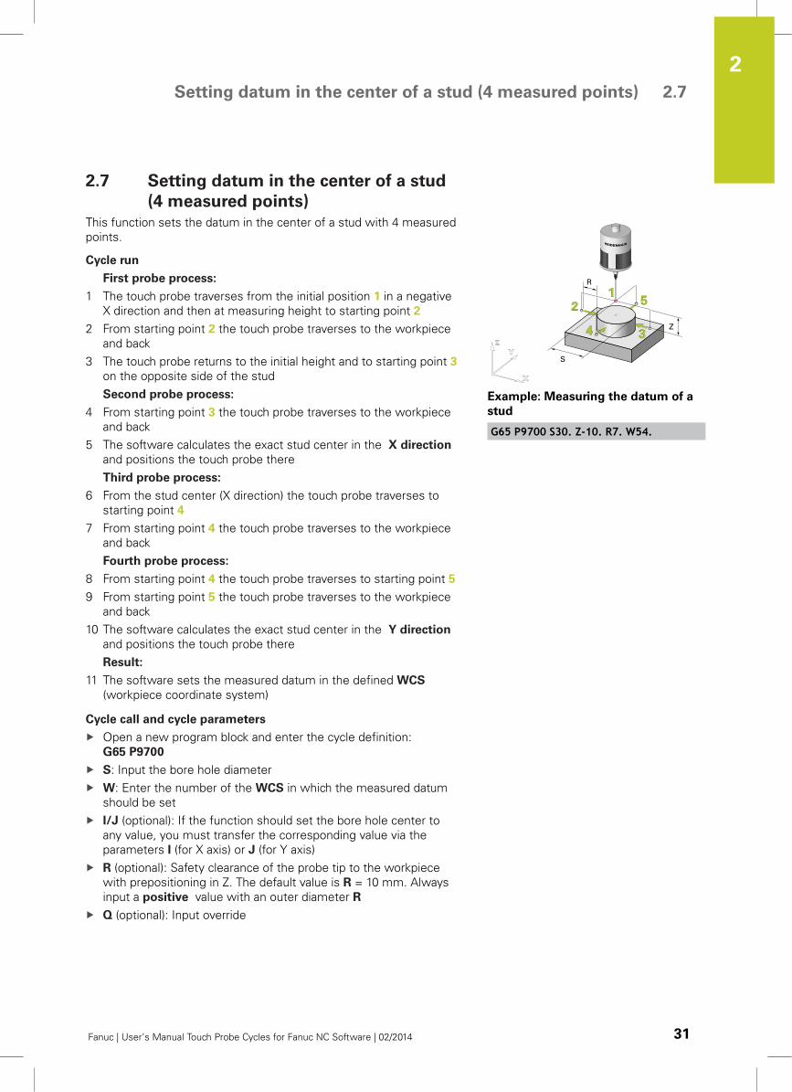
2.7 Setting datum in the center of a stud
(4 measured points)
This function sets the datum in the center of a stud with 4 measured
points.
Cycle run
First probe process:
1 The touch probe traverses from the initial position 1 in a negative
X direction and then at measuring height to starting point 2
2 From starting point 2 the touch probe traverses to the workpiece
and back
3 The touch probe returns to the initial height and to starting point 3
on the opposite side of the stud
Second probe process:
4 From starting point 3 the touch probe traverses to the workpiece
and back
5 The software calculates the exact stud center in the X direction
and positions the touch probe there
Third probe process:
6 From the stud center (X direction) the touch probe traverses to
starting point 4
7 From starting point 4 the touch probe traverses to the workpiece
and back
Fourth probe process:
8 From starting point 4 the touch probe traverses to starting point 5
9 From starting point 5 the touch probe traverses to the workpiece
and back
10 The software calculates the exact stud center in the Y direction
and positions the touch probe there
Result:
11 The software sets the measured datum in the defined WCS
(workpiece coordinate system)
Cycle call and cycle parameters
Open a new program block and enter the cycle definition:
G65 P9700
S: Input the bore hole diameter
W: Enter the number of the WCS in which the measured datum
should be set
I/J (optional): If the function should set the bore hole center to
any value, you must transfer the corresponding value via the
parameters I (for X axis) or J (for Y axis)
R (optional): Safety clearance of the probe tip to the workpiece
with prepositioning in Z. The default value is R = 10 mm. Always
input a positive value with an outer diameter R
Q (optional): Input override
Example: Measuring the datum of a
stud
G65 P9700 S30. Z-10. R7. W54.
Touch Probe Cycles: Automatically Measuring Workpieces 2.8 Setting datum in the center of a stud (3 measured points)
2
32 Fanuc | User’s Manual Touch Probe Cycles for Fanuc NC Software | 02/2014
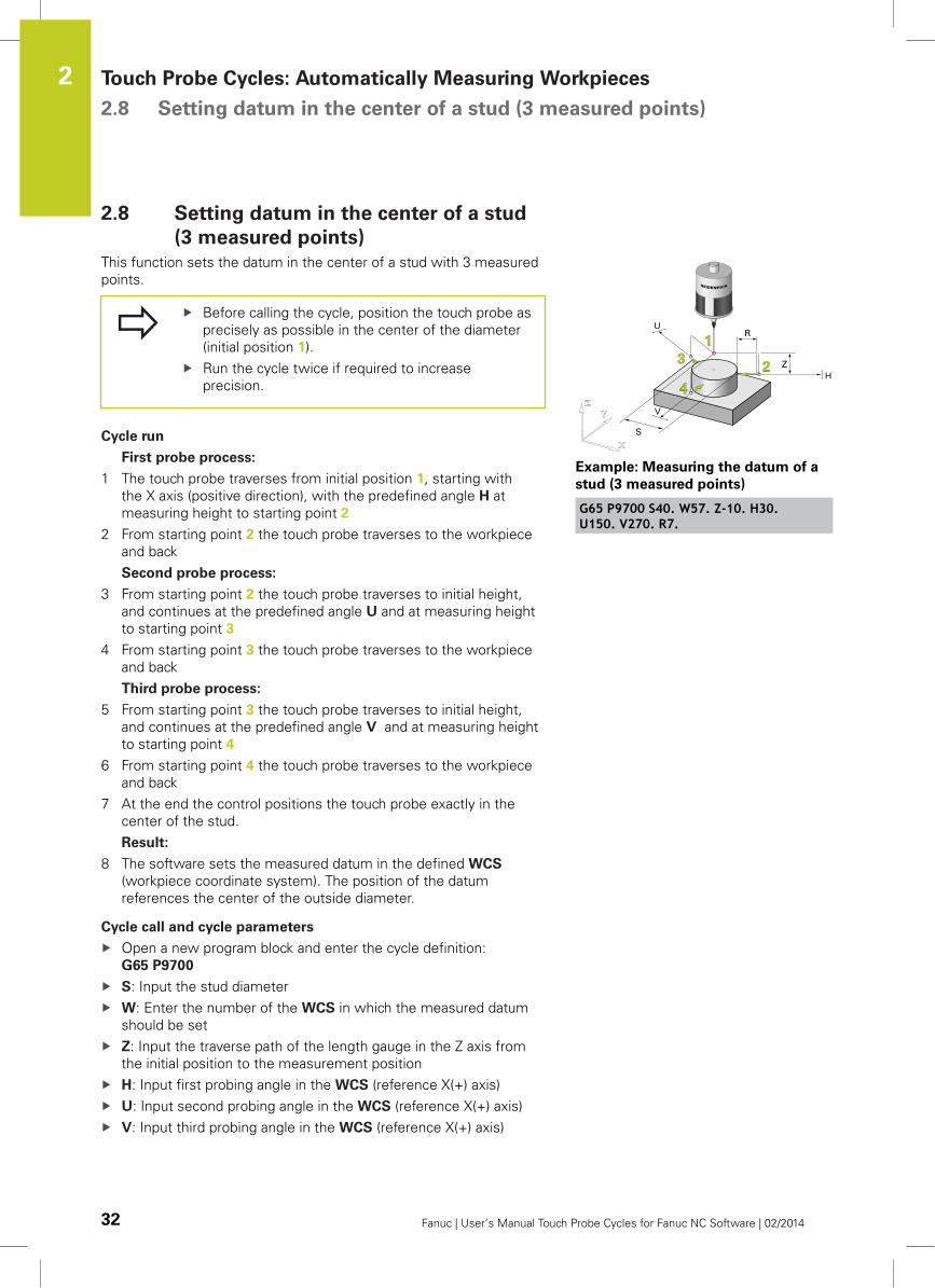
2.8 Setting datum in the center of a stud
(3 measured points)
This function sets the datum in the center of a stud with 3 measured
points.
Before calling the cycle, position the touch probe as
precisely as possible in the center of the diameter
(initial position 1).
Run the cycle twice if required to increase
precision.
Cycle run
First probe process:
1 The touch probe traverses from initial position 1, starting with
the X axis (positive direction), with the predefined angle H at
measuring height to starting point 2
2 From starting point 2 the touch probe traverses to the workpiece
and back
Second probe process:
3 From starting point 2 the touch probe traverses to initial height,
and continues at the predefined angle U and at measuring height
to starting point 3
4 From starting point 3 the touch probe traverses to the workpiece
and back
Third probe process:
5 From starting point 3 the touch probe traverses to initial height,
and continues at the predefined angle V and at measuring height
to starting point 4
6 From starting point 4 the touch probe traverses to the workpiece
and back
7 At the end the control positions the touch probe exactly in the
center of the stud.
Result:
8 The software sets the measured datum in the defined WCS
(workpiece coordinate system). The position of the datum
references the center of the outside diameter.
Cycle call and cycle parameters
Open a new program block and enter the cycle definition:
G65 P9700
S: Input the stud diameter
W: Enter the number of the WCS in which the measured datum
should be set
Z: Input the traverse path of the length gauge in the Z axis from
the initial position to the measurement position
H: Input first probing angle in the WCS (reference X(+) axis)
U: Input second probing angle in the WCS (reference X(+) axis)
V: Input third probing angle in the WCS (reference X(+) axis)
H
U
V
Example: Measuring the datum of a
stud (3 measured points)
G65 P9700 S40. W57. Z-10. H30.U150. V270. R7.
Setting datum in the center of a stud (3 measured points) 2.8
2
Fanuc | User’s Manual Touch Probe Cycles for Fanuc NC Software | 02/2014 33
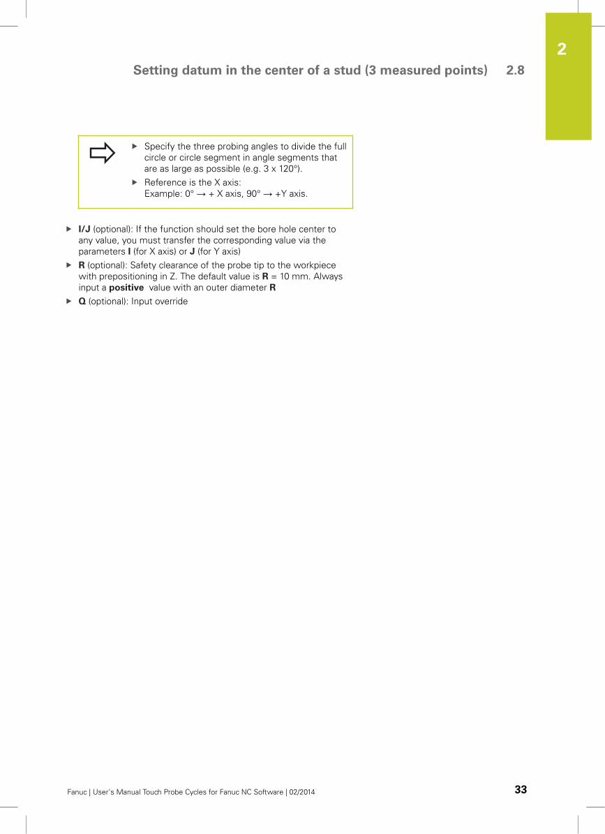
Specify the three probing angles to divide the full
circle or circle segment in angle segments that
are as large as possible (e.g. 3 x 120°).
Reference is the X axis:
Example: 0° → + X axis, 90° → +Y axis.
I/J (optional): If the function should set the bore hole center to
any value, you must transfer the corresponding value via the
parameters I (for X axis) or J (for Y axis)
R (optional): Safety clearance of the probe tip to the workpiece
with prepositioning in Z. The default value is R = 10 mm. Always
input a positive value with an outer diameter R
Q (optional): Input override
Touch Probe Cycles: Automatically Measuring Workpieces 2.9 Setting datum in the center of a slot
2
34 Fanuc | User’s Manual Touch Probe Cycles for Fanuc NC Software | 02/2014
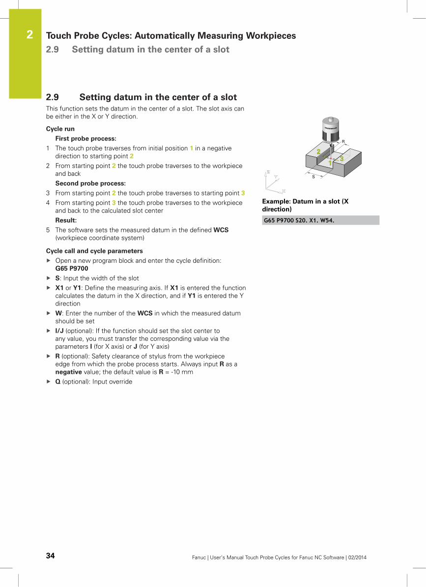
2.9 Setting datum in the center of a slot
This function sets the datum in the center of a slot. The slot axis can
be either in the X or Y direction.
Cycle run
First probe process:
1 The touch probe traverses from initial position 1 in a negative
direction to starting point 2
2 From starting point 2 the touch probe traverses to the workpiece
and back
Second probe process:
3 From starting point 2 the touch probe traverses to starting point 3
4 From starting point 3 the touch probe traverses to the workpiece
and back to the calculated slot center
Result:
5 The software sets the measured datum in the defined WCS
(workpiece coordinate system)
Cycle call and cycle parameters
Open a new program block and enter the cycle definition:
G65 P9700
S: Input the width of the slot
X1 or Y1: Define the measuring axis. If X1 is entered the function
calculates the datum in the X direction, and if Y1 is entered the Y
direction
W: Enter the number of the WCS in which the measured datum
should be set
I/J (optional): If the function should set the slot center to
any value, you must transfer the corresponding value via the
parameters I (for X axis) or J (for Y axis)
R (optional): Safety clearance of stylus from the workpiece
edge from which the probe process starts. Always input R as a
negative value; the default value is R = -10 mm
Q (optional): Input override
Example: Datum in a slot (X
direction)
G65 P9700 S20. X1. W54.
Setting datum in the center of a ridge 2.10
2
Fanuc | User’s Manual Touch Probe Cycles for Fanuc NC Software | 02/2014 35
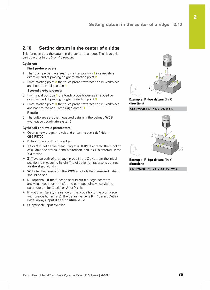
2.10 Setting datum in the center of a ridge
This function sets the datum in the center of a ridge. The ridge axis
can be either in the X or Y direction.
Cycle run
First probe process:
1 The touch probe traverses from initial position 1 in a negative
direction and at probing height to starting point 2
2 From starting point 2 the touch probe traverses to the workpiece
and back to initial position 1
Second probe process:
3 From initial position 1 the touch probe traverses in a positive
direction and at probing height to starting point 3
4 From starting point 3 the touch probe traverses to the workpiece
and back to the calculated ridge center 1
Result:
5 The software sets the measured datum in the defined WCS
(workpiece coordinate system)
Cycle call and cycle parameters
Open a new program block and enter the cycle definition:
G65 P9700
S: Input the width of the ridge
X1 or Y1: Define the measuring axis. If X1 is entered the function
calculates the datum in the X direction, and if Y1 is entered, in the
Y direction
Z: Traverse path of the touch probe in the Z axis from the initial
position to measuring height The direction of traverse is defined
via the algebraic sign
W: Enter the number of the WCS in which the measured datum
should be set
I/J (optional): If the function should set the ridge center to
any value, you must transfer the corresponding value via the
parameters I (for X axis) or J (for Y axis)
R (optional): Safety clearance of the probe tip to the workpiece
with prepositioning in Z. The default value is R = 10 mm. With a
ridge, always input R as a positive value
Q (optional): Input override
Example: Ridge datum (in X
direction)
G65 P9700 S20. X1. Z-20. W54.
Example: Ridge datum (in Y
direction)
G65 P9700 S20. Y1. Z-10. R7. W54.
Touch Probe Cycles: Automatically Measuring Workpieces 2.11 Setting datum in the center of a bore hole or center of a slot, each
with obstacle
2
36 Fanuc | User’s Manual Touch Probe Cycles for Fanuc NC Software | 02/2014
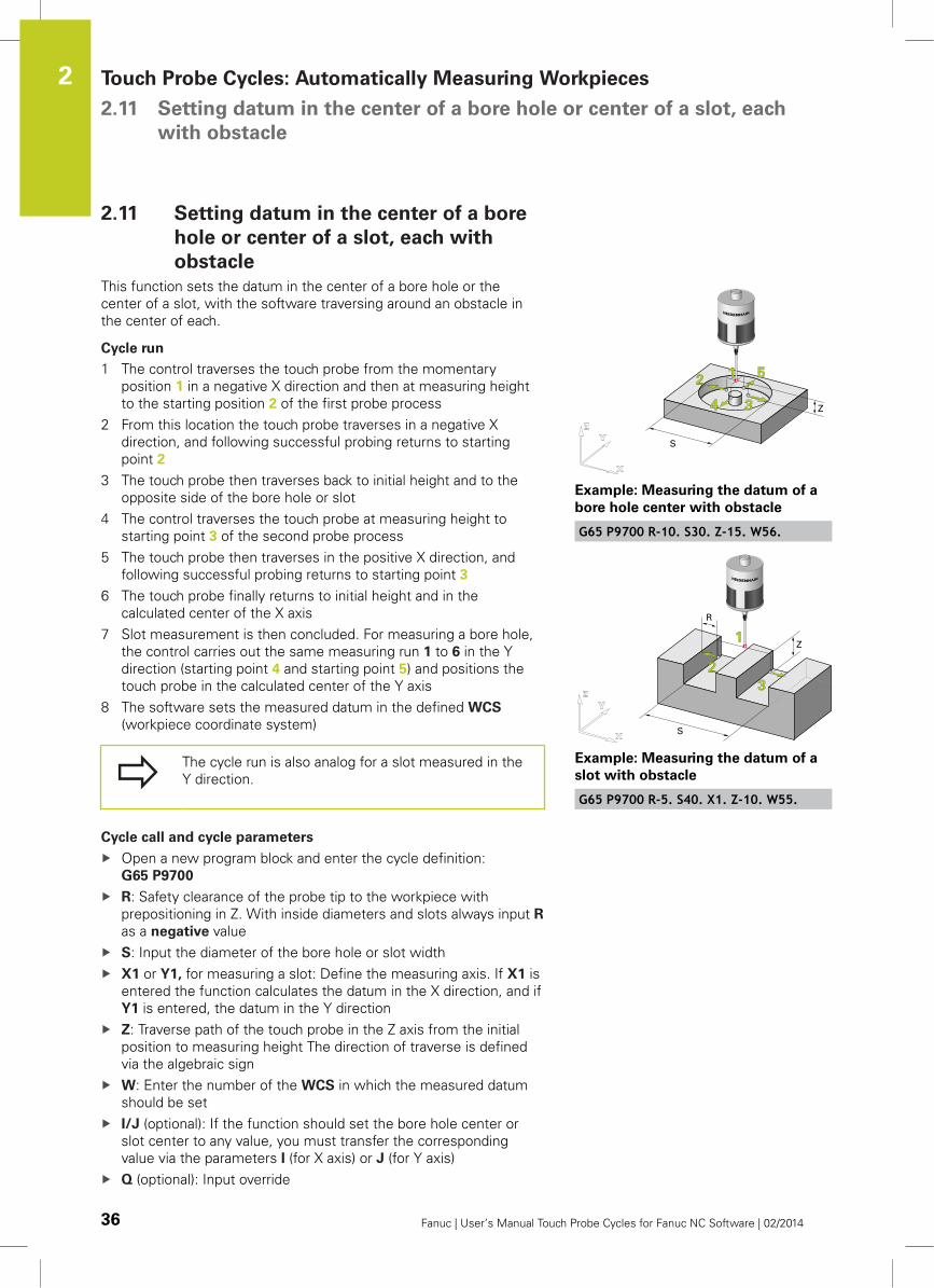
2.11 Setting datum in the center of a bore
hole or center of a slot, each with
obstacle
This function sets the datum in the center of a bore hole or the
center of a slot, with the software traversing around an obstacle in
the center of each.
Cycle run
1 The control traverses the touch probe from the momentary
position 1 in a negative X direction and then at measuring height
to the starting position 2 of the first probe process
2 From this location the touch probe traverses in a negative X
direction, and following successful probing returns to starting
point 2
3 The touch probe then traverses back to initial height and to the
opposite side of the bore hole or slot
4 The control traverses the touch probe at measuring height to
starting point 3 of the second probe process
5 The touch probe then traverses in the positive X direction, and
following successful probing returns to starting point 3
6 The touch probe finally returns to initial height and in the
calculated center of the X axis
7 Slot measurement is then concluded. For measuring a bore hole,
the control carries out the same measuring run 1 to 6 in the Y
direction (starting point 4 and starting point 5) and positions the
touch probe in the calculated center of the Y axis
8 The software sets the measured datum in the defined WCS
(workpiece coordinate system)
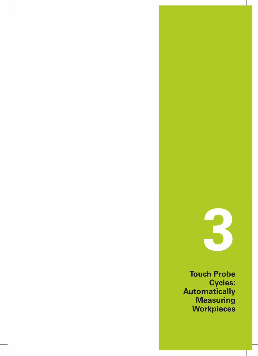
The cycle run is also analog for a slot measured in the
Y direction.
Cycle call and cycle parameters
Open a new program block and enter the cycle definition:
G65 P9700
R: Safety clearance of the probe tip to the workpiece with
prepositioning in Z. With inside diameters and slots always input R
as a negative value
S: Input the diameter of the bore hole or slot width
X1 or Y1, for measuring a slot: Define the measuring axis. If X1 is
entered the function calculates the datum in the X direction, and if
Y1 is entered, the datum in the Y direction
Z: Traverse path of the touch probe in the Z axis from the initial
position to measuring height The direction of traverse is defined
via the algebraic sign
W: Enter the number of the WCS in which the measured datum
should be set
I/J (optional): If the function should set the bore hole center or
slot center to any value, you must transfer the corresponding
value via the parameters I (for X axis) or J (for Y axis)
Q (optional): Input override
Example: Measuring the datum of a
bore hole center with obstacle
G65 P9700 R-10. S30. Z-15. W56.
Example: Measuring the datum of a
slot with obstacle
G65 P9700 R-5. S40. X1. Z-10. W55.
3Touch Probe
Cycles:Automatically
MeasuringWorkpieces
Touch Probe Cycles: Automatically Measuring Workpieces 3.1 Fundamentals of automatic measuring
3
38 Fanuc | User’s Manual Touch Probe Cycles for Fanuc NC Software | 02/2014
3.1 Fundamentals of automatic measuring
This chapter describes the functions for automatically measuring a
clamped workpiece.
The difference between probe cycles
for datum acquisition and for measuring:
For datum acquisition the dimensions in the program
call are relative to the workpiece, meaning the
distance from the probe tip to the workpiece is
entered.
With the measuring function, dimensions in the
program call are absolute to the workpiece, meaning
the program is given absolute coordinates about the
active WCS. This absolute dimensioning is identified
with the additional parameter A1. when calling the
program O9700 MAIN.
Pre-positioning the touch probe is implemented either with the
handwheel or the axis direction keys. You can alternatively pre-
position the touch probe with a "protected traversing block" (See
page 72).
Use the O9700 MAIN program to call all measurement functions.
The configuration of the parameters determines the type of
measurement position.
The software supports the following processes for measuring:
Function Page
Measuring a Single Point in any Axis page 40
Measuring a Corner in Two Axes page 41
Measuring a Corner in Three Axes page 43
Measuring a Slot page 53
Measuring a Ridge page 55
Measuring a Bore Hole (4 Measured Points) page 45
Measuring a Bore Hole (3 Measured Points) page 47
Measuring a Stud (Outside Diameter, 4 Measured
Points)
page 49
Measuring a Stud (Outside Diameter, 3 Measured
Points)
page 51
Measuring Bore Hole or Slot, Each with Obstacle page 57
Detailed descriptions of optional parameters: See
"Call parameters", page 86.
Fundamentals of automatic measuring 3.1
3
Fanuc | User’s Manual Touch Probe Cycles for Fanuc NC Software | 02/2014 39
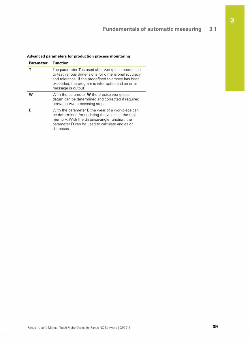
Advanced parameters for production process monitoring
Parameter Function
T The parameter T is used after workpiece production
to test various dimensions for dimensional accuracy
and tolerance. If the predefined tolerance has been
exceeded, the program is interrupted and an error
message is output.
W With the parameter W the precise workpiece
datum can be determined and corrected if required
between two processing steps.
E With the parameter E the wear of a workpiece can
be determined for updating the values in the tool
memory. With the distance-angle function, the
parameter D can be used to calculate angles or
distances.
Touch Probe Cycles: Automatically Measuring Workpieces 3.2 Measuring a Single Point in any Axis
3
40 Fanuc | User’s Manual Touch Probe Cycles for Fanuc NC Software | 02/2014
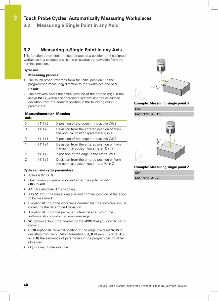
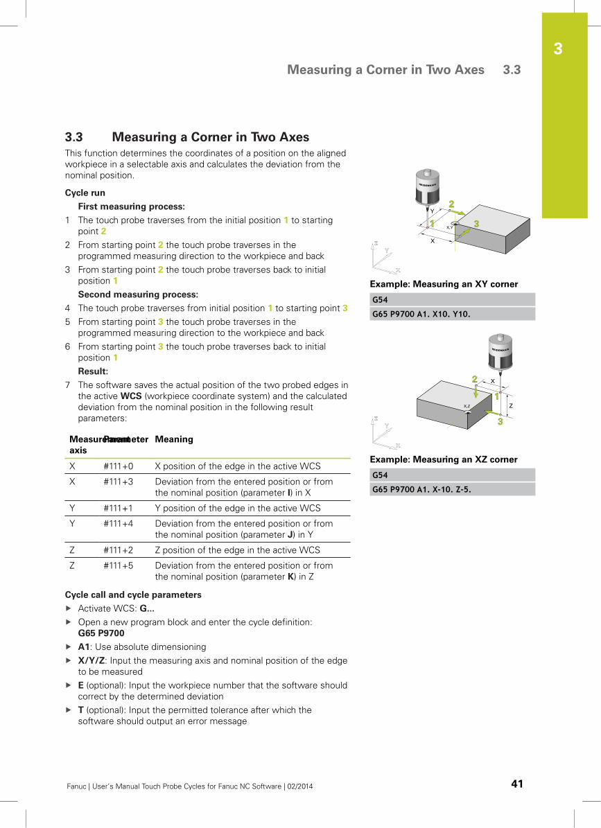
3.2 Measuring a Single Point in any Axis
This function determines the coordinates of a position on the aligned
workpiece in a selectable axis and calculates the deviation from the
nominal position.
Cycle run
Measuring process:
1 The touch probe traverses from the initial position 1 in the
programmed measuring direction to the workpiece and back
Result:
2 The software saves the actual position of the probed edge in the
active WCS (workpiece coordinate system) and the calculated
deviation from the nominal position in the following result
parameters:
Measurement
axis
Parameter Meaning
X #111+0 X position of the edge in the active WCS
X #111+3 Deviation from the entered position or from
the nominal position (parameter I) in X
Y #111+1 Y position of the edge in the active WCS
Y #111+4 Deviation from the entered position or from
the nominal position (parameter J) in Y
Z #111+2 Z position of the edge in the active WCS
Z #111+5 Deviation from the entered position or from
the nominal position (parameter K) in Z
Cycle call and cycle parameters
Activate WCS: G...
Open a new program block and enter the cycle definition:
G65 P9700
A1: Use absolute dimensioning
X/Y/Z: Input the measuring axis and nominal position of the edge
to be measured
E (optional): Input the workpiece number that the software should
correct by the determined deviation
T (optional): Input the permitted tolerance after which the
software should output an error message
W (optional): Input the number of the WCS that you wish to set or
correct
I/J/K (optional): Nominal position of the edge in a reset WCS if
deviating from zero. With parameters I, J, K (X axis: I, Y axis: J, Z
axis: K) the sequence of parameters in the program call must be
observed.
Q (optional): Enter override
Example: Measuring single point X
G54
G65 P9700 A1. X0.
Example: Measuring single point Z
G54
G65 P9700 A1. Z0.
Measuring a Corner in Two Axes 3.3
3
Fanuc | User’s Manual Touch Probe Cycles for Fanuc NC Software | 02/2014 41
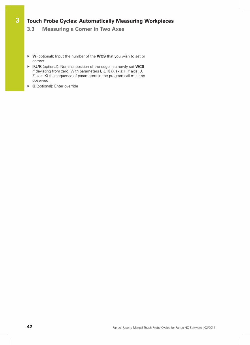
3.3 Measuring a Corner in Two Axes
This function determines the coordinates of a position on the aligned
workpiece in a selectable axis and calculates the deviation from the
nominal position.
Cycle run
First measuring process:
1 The touch probe traverses from the initial position 1 to starting
point 2
2 From starting point 2 the touch probe traverses in the
programmed measuring direction to the workpiece and back
3 From starting point 2 the touch probe traverses back to initial
position 1
Second measuring process:
4 The touch probe traverses from initial position 1 to starting point 3
5 From starting point 3 the touch probe traverses in the
programmed measuring direction to the workpiece and back
6 From starting point 3 the touch probe traverses back to initial
position 1
Result:
7 The software saves the actual position of the two probed edges in
the active WCS (workpiece coordinate system) and the calculated
deviation from the nominal position in the following result
parameters:
Measurement
axis
Parameter Meaning
X #111+0 X position of the edge in the active WCS
X #111+3 Deviation from the entered position or from
the nominal position (parameter I) in X
Y #111+1 Y position of the edge in the active WCS
Y #111+4 Deviation from the entered position or from
the nominal position (parameter J) in Y
Z #111+2 Z position of the edge in the active WCS
Z #111+5 Deviation from the entered position or from
the nominal position (parameter K) in Z
Cycle call and cycle parameters
Activate WCS: G...
Open a new program block and enter the cycle definition:
G65 P9700
A1: Use absolute dimensioning
X/Y/Z: Input the measuring axis and nominal position of the edge
to be measured
E (optional): Input the workpiece number that the software should
correct by the determined deviation
T (optional): Input the permitted tolerance after which the
software should output an error message
Example: Measuring an XY corner
G54
G65 P9700 A1. X10. Y10.
Example: Measuring an XZ corner
G54
G65 P9700 A1. X-10. Z-5.
Touch Probe Cycles: Automatically Measuring Workpieces 3.3 Measuring a Corner in Two Axes
3
42 Fanuc | User’s Manual Touch Probe Cycles for Fanuc NC Software | 02/2014
W (optional): Input the number of the WCS that you wish to set or
correct
I/J/K (optional): Nominal position of the edge in a newly set WCS
if deviating from zero. With parameters I, J, K (X axis: I, Y axis: J,
Z axis: K) the sequence of parameters in the program call must be
observed.
Q (optional): Enter override
Measuring a Corner in Three Axes 3.4
3
Fanuc | User’s Manual Touch Probe Cycles for Fanuc NC Software | 02/2014 43
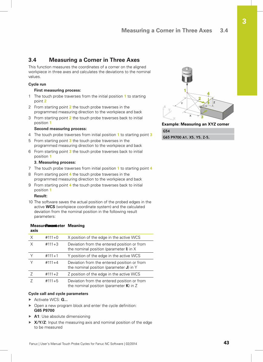
3.4 Measuring a Corner in Three Axes
This function measures the coordinates of a corner on the aligned
workpiece in three axes and calculates the deviations to the nominal
values.
Cycle run
First measuring process:
1 The touch probe traverses from the initial position 1 to starting
point 2
2 From starting point 2 the touch probe traverses in the
programmed measuring direction to the workpiece and back
3 From starting point 2 the touch probe traverses back to initial
position 1
Second measuring process:
4 The touch probe traverses from initial position 1 to starting point 3
5 From starting point 3 the touch probe traverses in the
programmed measuring direction to the workpiece and back
6 From starting point 3 the touch probe traverses back to initial
position 1
3. Measuring process:
7 The touch probe traverses from initial position 1 to starting point 4
8 From starting point 4 the touch probe traverses in the
programmed measuring direction to the workpiece and back
9 From starting point 4 the touch probe traverses back to initial
position 1
Result:
10 The software saves the actual position of the probed edges in the
active WCS (workpiece coordinate system) and the calculated
deviation from the nominal position in the following result
parameters:
Measurement
axis
Parameter Meaning
X #111+0 X position of the edge in the active WCS
X #111+3 Deviation from the entered position or from
the nominal position (parameter I) in X
Y #111+1 Y position of the edge in the active WCS
Y #111+4 Deviation from the entered position or from
the nominal position (parameter J) in Y
Z #111+2 Z position of the edge in the active WCS
Z #111+5 Deviation from the entered position or from
the nominal position (parameter K) in Z
Cycle call and cycle parameters
Activate WCS: G...
Open a new program block and enter the cycle definition:
G65 P9700
A1: Use absolute dimensioning
X/Y/Z: Input the measuring axis and nominal position of the edge
to be measured
Example: Measuring an XYZ corner
G54
G65 P9700 A1. X5. Y5. Z-5.
Touch Probe Cycles: Automatically Measuring Workpieces 3.4 Measuring a Corner in Three Axes
3
44 Fanuc | User’s Manual Touch Probe Cycles for Fanuc NC Software | 02/2014
E (optional): Input the workpiece number that the software should
correct by the determined deviation
T (optional): Input the permitted tolerance after which the
software should output an error message
W (optional): Input the number of the WCS that you wish to set or
correct
I/J/K (optional): Nominal position of the edge in a newly set WCS
if deviating from zero. With parameters I, J, K (X axis: I, Y axis: J,
Z axis: K) the sequence of parameters in the program call must be
observed.
Q (optional): Enter override
Measuring a Bore Hole (4 Measured Points) 3.5
3
Fanuc | User’s Manual Touch Probe Cycles for Fanuc NC Software | 02/2014 45
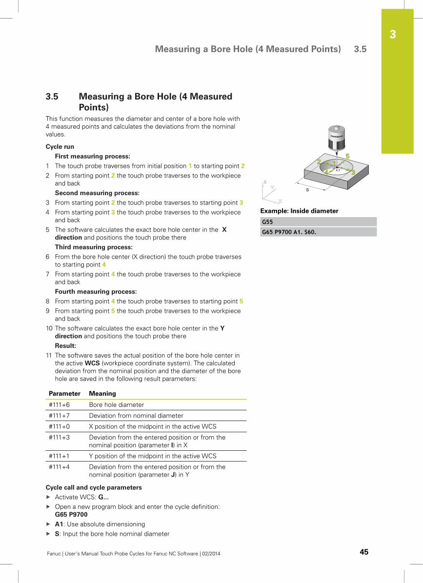
3.5 Measuring a Bore Hole (4 Measured
Points)
This function measures the diameter and center of a bore hole with
4 measured points and calculates the deviations from the nominal
values.
Cycle run
First measuring process:
1 The touch probe traverses from initial position 1 to starting point 2
2 From starting point 2 the touch probe traverses to the workpiece
and back
Second measuring process:
3 From starting point 2 the touch probe traverses to starting point 3
4 From starting point 3 the touch probe traverses to the workpiece
and back
5 The software calculates the exact bore hole center in the X
direction and positions the touch probe there
Third measuring process:
6 From the bore hole center (X direction) the touch probe traverses
to starting point 4
7 From starting point 4 the touch probe traverses to the workpiece
and back
Fourth measuring process:
8 From starting point 4 the touch probe traverses to starting point 5
9 From starting point 5 the touch probe traverses to the workpiece
and back
10 The software calculates the exact bore hole center in the Y
direction and positions the touch probe there
Result:
11 The software saves the actual position of the bore hole center in
the active WCS (workpiece coordinate system). The calculated
deviation from the nominal position and the diameter of the bore
hole are saved in the following result parameters:
Parameter Meaning
#111+6 Bore hole diameter
#111+7 Deviation from nominal diameter
#111+0 X position of the midpoint in the active WCS
#111+3 Deviation from the entered position or from the
nominal position (parameter I) in X
#111+1 Y position of the midpoint in the active WCS
#111+4 Deviation from the entered position or from the
nominal position (parameter J) in Y
Cycle call and cycle parameters
Activate WCS: G...
Open a new program block and enter the cycle definition:
G65 P9700
A1: Use absolute dimensioning
S: Input the bore hole nominal diameter
Example: Inside diameter
G55
G65 P9700 A1. S60.
Touch Probe Cycles: Automatically Measuring Workpieces 3.5 Measuring a Bore Hole (4 Measured Points)
3
46 Fanuc | User’s Manual Touch Probe Cycles for Fanuc NC Software | 02/2014
E (optional): Input the workpiece number that the software should
correct by the determined deviation
T (optional): Input the permitted tolerance after which the
software should output an error message
W (optional): Input the number of the WCS that you wish to set or
correct
I/J (optional): Nominal position of the edge in a newly set WCS if
deviating from zero. With parameters I, J (X axis: I, Y axis: J) the
sequence of parameters in the program call must be observed.
Q (optional): Enter override
Measuring a Bore Hole (3 Measured Points) 3.6
3
Fanuc | User’s Manual Touch Probe Cycles for Fanuc NC Software | 02/2014 47
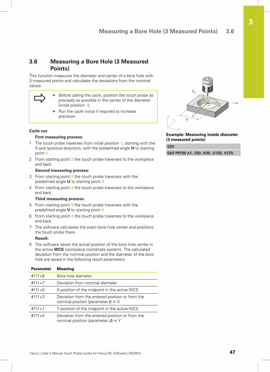
3.6 Measuring a Bore Hole (3 Measured
Points)
This function measures the diameter and center of a bore hole with
3 measured points and calculates the deviations from the nominal
values.
Before calling the cycle, position the touch probe as
precisely as possible in the center of the diameter
(initial position 1).
Run the cycle twice if required to increase
precision.
Cycle run
First measuring process:
1 The touch probe traverses from initial position 1, starting with the
X axis (positive direction), with the predefined angle H to starting
point 2
2 From starting point 2 the touch probe traverses to the workpiece
and back
Second measuring process:
3 From starting point 2 the touch probe traverses with the
predefined angle U to starting point 3
4 From starting point 3 the touch probe traverses to the workpiece
and back
Third measuring process:
5 From starting point 3 the touch probe traverses with the
predefined angle V to starting point 4
6 From starting point 4 the touch probe traverses to the workpiece
and back
7 The software calculates the exact bore hole center and positions
the touch probe there
Result:
8 The software saves the actual position of the bore hole center in
the active WCS (workpiece coordinate system). The calculated
deviation from the nominal position and the diameter of the bore
hole are saved in the following result parameters:
Parameter Meaning
#111+6 Bore hole diameter
#111+7 Deviation from nominal diameter
#111+0 X position of the midpoint in the active WCS
#111+3 Deviation from the entered position or from the
nominal position (parameter I) in X
#111+1 Y position of the midpoint in the active WCS
#111+4 Deviation from the entered position or from the
nominal position (parameter J) in Y
Example: Measuring inside diameter
(3 measured points)
G55
G65 P9700 A1. S50. H30. U150. V270.
Touch Probe Cycles: Automatically Measuring Workpieces 3.6 Measuring a Bore Hole (3 Measured Points)
3
48 Fanuc | User’s Manual Touch Probe Cycles for Fanuc NC Software | 02/2014
Cycle call and cycle parameters
Activate WCS: G...
Open a new program block and enter the cycle definition:
G65 P9700
A1.: Use absolute dimensioning
S: Input the bore hole nominal diameter
E (optional): Input the workpiece number that the software should
correct by the determined deviation
H: Input first probing angle in the WCS (reference X(+) axis)
U: Input second probing angle in the WCS (reference X(+) axis)
V: Input third probing angle in the WCS (reference X(+) axis)
Specify the three probing angles to divide the full
circle or circle segment in angle segments that
are as large as possible (e.g. 3 x 120°).
Reference is the X axis:
Example: 0° → + X axis, 90° → +Y axis.
T (optional): Input the permitted tolerance after which the
software should output an error message
W (optional): Input the number of the WCS that you wish to set or
correct
I/J (optional): Nominal position of the edge in a newly set WCS if
deviating from zero. With parameters I, J (X axis: I, Y axis: J) the
sequence of parameters in the program call must be observed.
Q (optional): Enter override
Measuring a Stud (Outside Diameter, 4 Measured Points) 3.7
3
Fanuc | User’s Manual Touch Probe Cycles for Fanuc NC Software | 02/2014 49
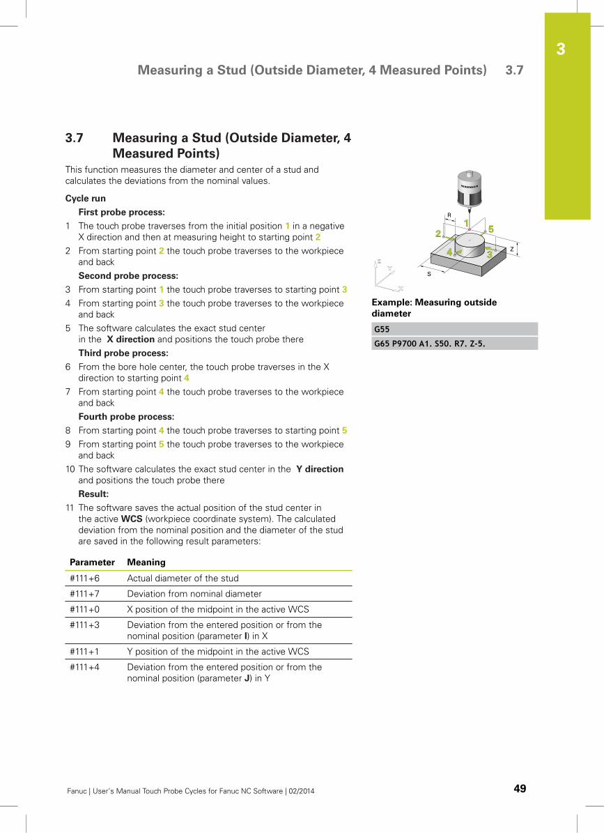
3.7 Measuring a Stud (Outside Diameter, 4
Measured Points)
This function measures the diameter and center of a stud and
calculates the deviations from the nominal values.
Cycle run
First probe process:
1 The touch probe traverses from the initial position 1 in a negative
X direction and then at measuring height to starting point 2
2 From starting point 2 the touch probe traverses to the workpiece
and back
Second probe process:
3 From starting point 1 the touch probe traverses to starting point 3
4 From starting point 3 the touch probe traverses to the workpiece
and back
5 The software calculates the exact stud center
in the X direction and positions the touch probe there
Third probe process:
6 From the bore hole center, the touch probe traverses in the X
direction to starting point 4
7 From starting point 4 the touch probe traverses to the workpiece
and back
Fourth probe process:
8 From starting point 4 the touch probe traverses to starting point 5
9 From starting point 5 the touch probe traverses to the workpiece
and back
10 The software calculates the exact stud center in the Y direction
and positions the touch probe there
Result:
11 The software saves the actual position of the stud center in
the active WCS (workpiece coordinate system). The calculated
deviation from the nominal position and the diameter of the stud
are saved in the following result parameters:
Parameter Meaning
#111+6 Actual diameter of the stud
#111+7 Deviation from nominal diameter
#111+0 X position of the midpoint in the active WCS
#111+3 Deviation from the entered position or from the
nominal position (parameter I) in X
#111+1 Y position of the midpoint in the active WCS
#111+4 Deviation from the entered position or from the
nominal position (parameter J) in Y
Example: Measuring outside
diameter
G55
G65 P9700 A1. S50. R7. Z-5.
Touch Probe Cycles: Automatically Measuring Workpieces 3.7 Measuring a Stud (Outside Diameter, 4 Measured Points)
3
50 Fanuc | User’s Manual Touch Probe Cycles for Fanuc NC Software | 02/2014
Cycle call and cycle parameters
Activate WCS: G...
Open a new program block and enter the cycle definition:
G65 P9700
A1.: Use absolute dimensioning
S: Input the bore hole diameter
Z: Measurement position in the Z axis in the active WCS. The
datum for positioning in Z is the ball tip center
E: Tool number of the tool to be corrected
T: Position tolerance of the midpoint (T negative), or tolerance of
the diameter (T positive)
W: Enter the number of the WCS in which the measured datum
should be set
I/J (optional): If the function should set the bore hole center to
any value, you must transfer the corresponding value via the
parameters I (for X axis) or J (for Y axis)
R (optional): Safety clearance of the probe tip to the workpiece
with prepositioning in Z. The default value is R = 10 mm. Always
input a positive value with an outer diameter R
Q (optional): Input override
Measuring a Stud (Outside Diameter, 3 Measured Points) 3.8
3
Fanuc | User’s Manual Touch Probe Cycles for Fanuc NC Software | 02/2014 51
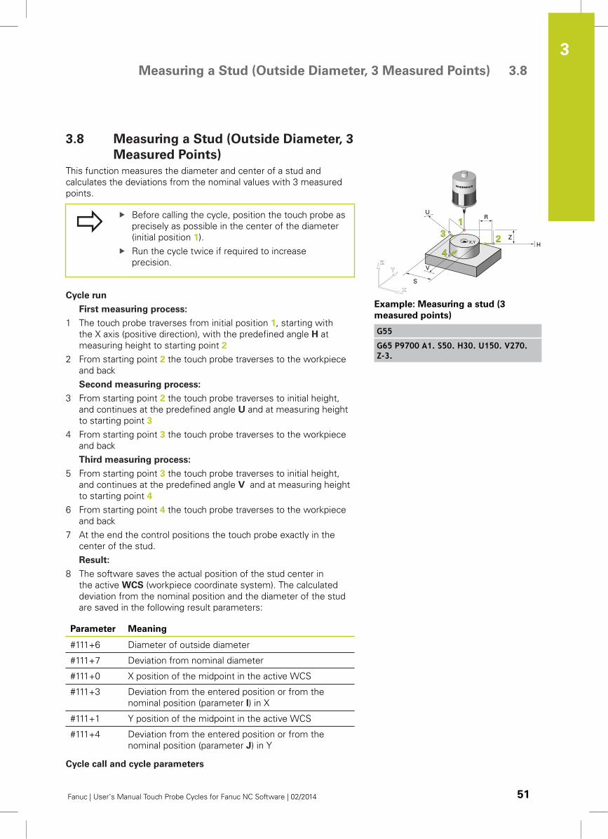
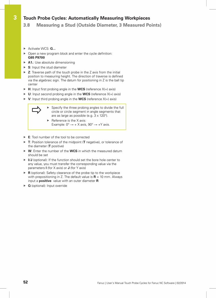
3.8 Measuring a Stud (Outside Diameter, 3
Measured Points)
This function measures the diameter and center of a stud and
calculates the deviations from the nominal values with 3 measured
points.
Before calling the cycle, position the touch probe as
precisely as possible in the center of the diameter
(initial position 1).
Run the cycle twice if required to increase
precision.
Cycle run
First measuring process:
1 The touch probe traverses from initial position 1, starting with
the X axis (positive direction), with the predefined angle H at
measuring height to starting point 2
2 From starting point 2 the touch probe traverses to the workpiece
and back
Second measuring process:
3 From starting point 2 the touch probe traverses to initial height,
and continues at the predefined angle U and at measuring height
to starting point 3
4 From starting point 3 the touch probe traverses to the workpiece
and back
Third measuring process:
5 From starting point 3 the touch probe traverses to initial height,
and continues at the predefined angle V and at measuring height
to starting point 4
6 From starting point 4 the touch probe traverses to the workpiece
and back
7 At the end the control positions the touch probe exactly in the
center of the stud.
Result:
8 The software saves the actual position of the stud center in
the active WCS (workpiece coordinate system). The calculated
deviation from the nominal position and the diameter of the stud
are saved in the following result parameters:
Parameter Meaning
#111+6 Diameter of outside diameter
#111+7 Deviation from nominal diameter
#111+0 X position of the midpoint in the active WCS
#111+3 Deviation from the entered position or from the
nominal position (parameter I) in X
#111+1 Y position of the midpoint in the active WCS
#111+4 Deviation from the entered position or from the
nominal position (parameter J) in Y
Cycle call and cycle parameters
Example: Measuring a stud (3
measured points)
G55
G65 P9700 A1. S50. H30. U150. V270.Z-3.
Touch Probe Cycles: Automatically Measuring Workpieces 3.8 Measuring a Stud (Outside Diameter, 3 Measured Points)
3
52 Fanuc | User’s Manual Touch Probe Cycles for Fanuc NC Software | 02/2014
Activate WCS: G...
Open a new program block and enter the cycle definition:
G65 P9700
A1.: Use absolute dimensioning
S: Input the stud diameter
Z: Traverse path of the touch probe in the Z axis from the initial
position to measuring height. The direction of traverse is defined
via the algebraic sign. The datum for positioning in Z is the ball tip
center
H: Input first probing angle in the WCS (reference X(+) axis)
U: Input second probing angle in the WCS (reference X(+) axis)
V: Input third probing angle in the WCS (reference X(+) axis)
Specify the three probing angles to divide the full
circle or circle segment in angle segments that
are as large as possible (e.g. 3 x 120°).
Reference is the X axis:
Example: 0° → + X axis, 90° → +Y axis.
E: Tool number of the tool to be corrected
T: Position tolerance of the midpoint (T negative), or tolerance of
the diameter (T positive)
W: Enter the number of the WCS in which the measured datum
should be set
I/J (optional): If the function should set the bore hole center to
any value, you must transfer the corresponding value via the
parameters I (for X axis) or J (for Y axis)
R (optional): Safety clearance of the probe tip to the workpiece
with prepositioning in Z. The default value is R = 10 mm. Always
input a positive value with an outer diameter R
Q (optional): Input override
Measuring a Slot 3.9
3
Fanuc | User’s Manual Touch Probe Cycles for Fanuc NC Software | 02/2014 53
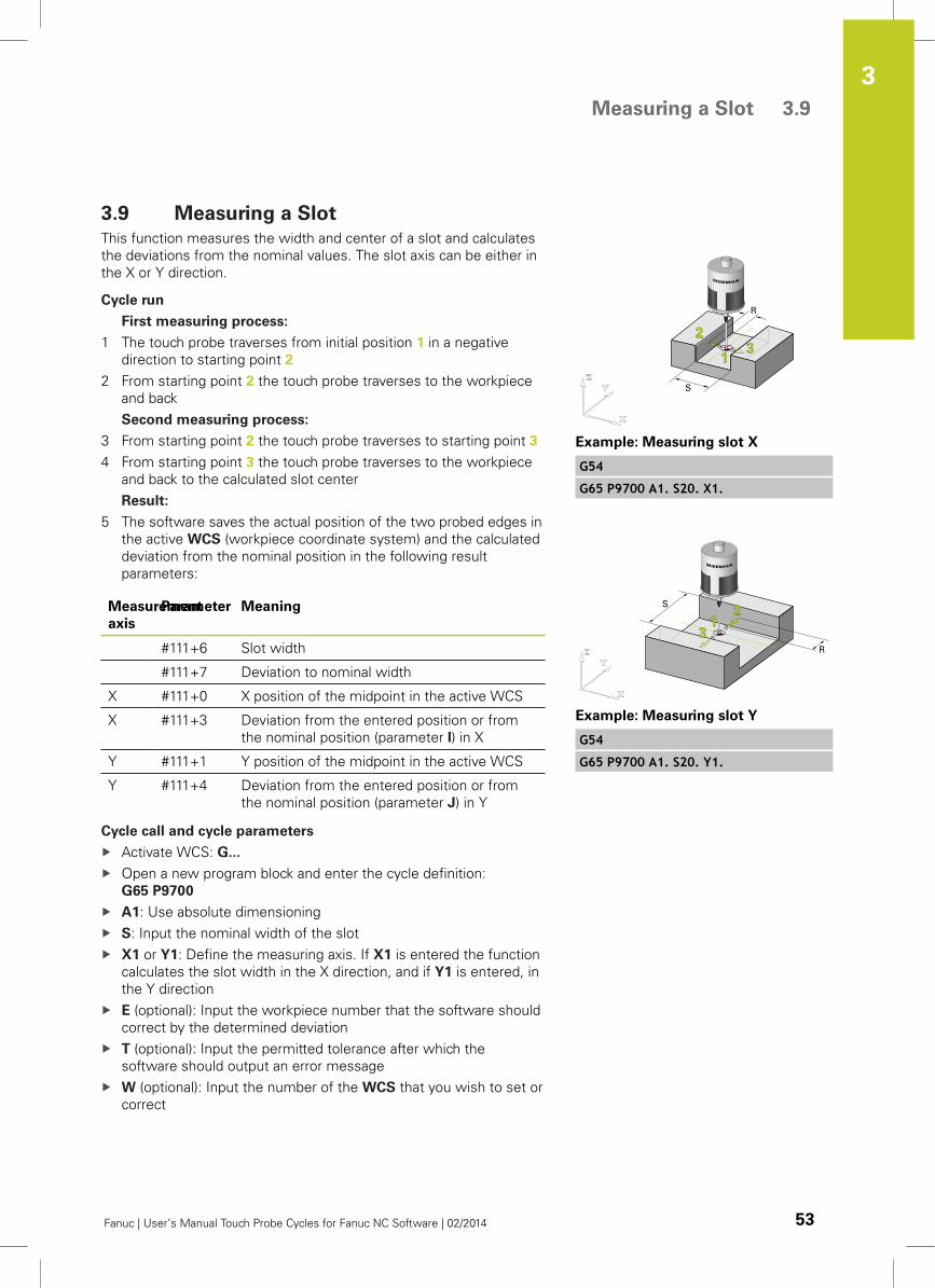
3.9 Measuring a Slot
This function measures the width and center of a slot and calculates
the deviations from the nominal values. The slot axis can be either in
the X or Y direction.
Cycle run
First measuring process:
1 The touch probe traverses from initial position 1 in a negative
direction to starting point 2
2 From starting point 2 the touch probe traverses to the workpiece
and back
Second measuring process:
3 From starting point 2 the touch probe traverses to starting point 3
4 From starting point 3 the touch probe traverses to the workpiece
and back to the calculated slot center
Result:
5 The software saves the actual position of the two probed edges in
the active WCS (workpiece coordinate system) and the calculated
deviation from the nominal position in the following result
parameters:
Measurement
axis
Parameter Meaning
#111+6 Slot width
#111+7 Deviation to nominal width
X #111+0 X position of the midpoint in the active WCS
X #111+3 Deviation from the entered position or from
the nominal position (parameter I) in X
Y #111+1 Y position of the midpoint in the active WCS
Y #111+4 Deviation from the entered position or from
the nominal position (parameter J) in Y
Cycle call and cycle parameters
Activate WCS: G...
Open a new program block and enter the cycle definition:
G65 P9700
A1: Use absolute dimensioning
S: Input the nominal width of the slot
X1 or Y1: Define the measuring axis. If X1 is entered the function
calculates the slot width in the X direction, and if Y1 is entered, in
the Y direction
E (optional): Input the workpiece number that the software should
correct by the determined deviation
T (optional): Input the permitted tolerance after which the
software should output an error message
W (optional): Input the number of the WCS that you wish to set or
correct
Example: Measuring slot X
G54
G65 P9700 A1. S20. X1.
Example: Measuring slot Y
G54
G65 P9700 A1. S20. Y1.
Touch Probe Cycles: Automatically Measuring Workpieces 3.9 Measuring a Slot
3
54 Fanuc | User’s Manual Touch Probe Cycles for Fanuc NC Software | 02/2014
I/J (optional): Nominal position of the edge in a newly set WCS if
deviating from zero. With parameters I, J (X axis: I, Y axis: J) the
sequence of parameters in the program call must be observed.
R (optional): Safety clearance of the stylus from the workpiece
edge from which the probe process starts. Always input R as a
negative value; the default value is R = -10mm
Q (optional): Enter override
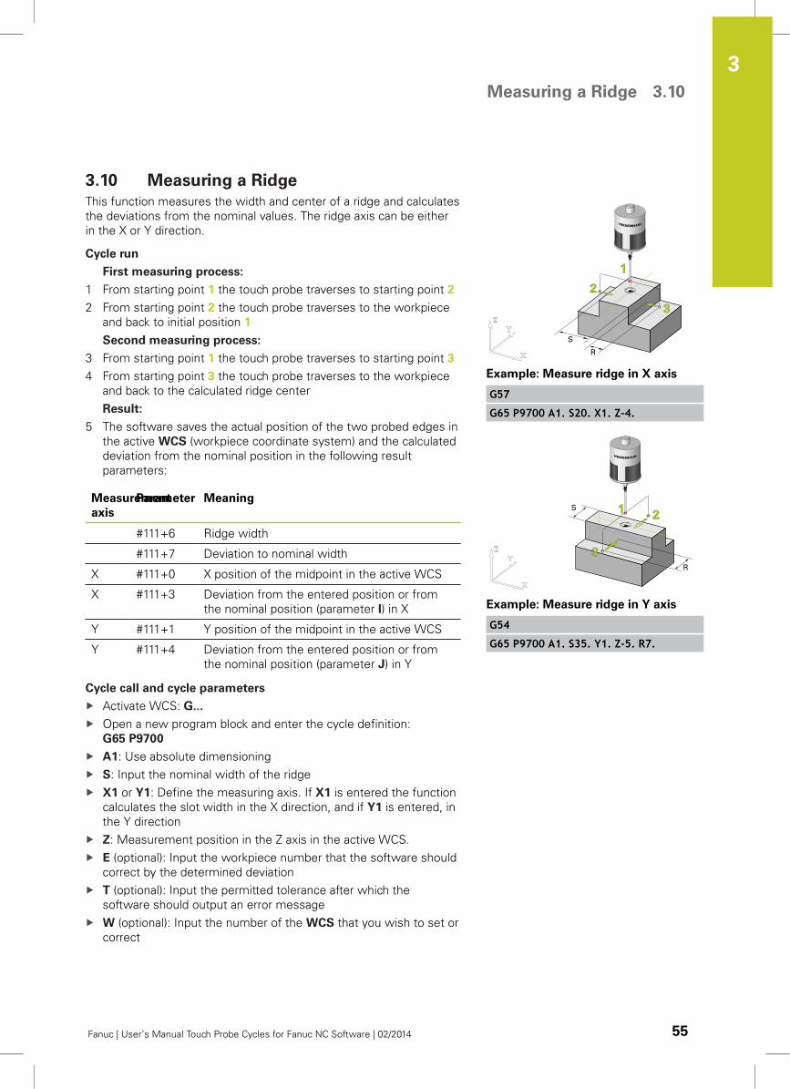
Measuring a Ridge 3.10
3
Fanuc | User’s Manual Touch Probe Cycles for Fanuc NC Software | 02/2014 55
3.10 Measuring a Ridge
This function measures the width and center of a ridge and calculates
the deviations from the nominal values. The ridge axis can be either
in the X or Y direction.
Cycle run
First measuring process:
1 From starting point 1 the touch probe traverses to starting point 2
2 From starting point 2 the touch probe traverses to the workpiece
and back to initial position 1
Second measuring process:
3 From starting point 1 the touch probe traverses to starting point 3
4 From starting point 3 the touch probe traverses to the workpiece
and back to the calculated ridge center
Result:
5 The software saves the actual position of the two probed edges in
the active WCS (workpiece coordinate system) and the calculated
deviation from the nominal position in the following result
parameters:
Measurement
axis
Parameter Meaning
#111+6 Ridge width
#111+7 Deviation to nominal width
X #111+0 X position of the midpoint in the active WCS
X #111+3 Deviation from the entered position or from
the nominal position (parameter I) in X
Y #111+1 Y position of the midpoint in the active WCS
Y #111+4 Deviation from the entered position or from
the nominal position (parameter J) in Y
Cycle call and cycle parameters
Activate WCS: G...
Open a new program block and enter the cycle definition:
G65 P9700
A1: Use absolute dimensioning
S: Input the nominal width of the ridge
X1 or Y1: Define the measuring axis. If X1 is entered the function
calculates the slot width in the X direction, and if Y1 is entered, in
the Y direction
Z: Measurement position in the Z axis in the active WCS.
E (optional): Input the workpiece number that the software should
correct by the determined deviation
T (optional): Input the permitted tolerance after which the
software should output an error message
W (optional): Input the number of the WCS that you wish to set or
correct
Example: Measure ridge in X axis
G57
G65 P9700 A1. S20. X1. Z-4.
Example: Measure ridge in Y axis
G54
G65 P9700 A1. S35. Y1. Z-5. R7.
Touch Probe Cycles: Automatically Measuring Workpieces 3.10 Measuring a Ridge
3
56 Fanuc | User’s Manual Touch Probe Cycles for Fanuc NC Software | 02/2014
I/J (optional): Nominal position of the edge in a newly set WCS if
deviating from zero. With parameters I, J (X axis: I, Y axis: J) the
sequence of parameters in the program call must be observed.
R (optional): Safety clearance of the probe tip to the workpiece
with prepositioning in Z. The default value is R = 10 mm. With a
ridge, always input R as a positive value
Q (optional): Enter override
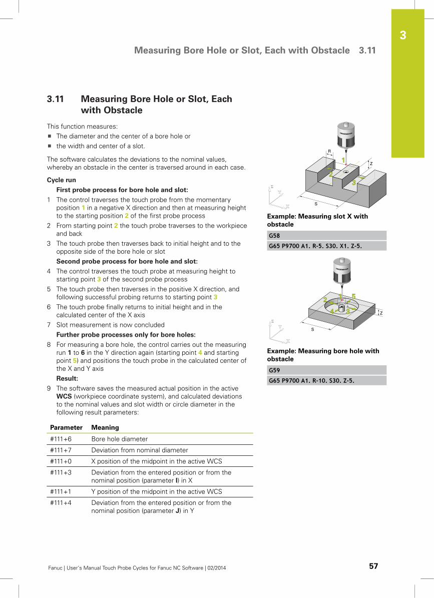
Measuring Bore Hole or Slot, Each with Obstacle 3.11
3
Fanuc | User’s Manual Touch Probe Cycles for Fanuc NC Software | 02/2014 57
3.11 Measuring Bore Hole or Slot, Each
with Obstacle
This function measures:
The diameter and the center of a bore hole or
the width and center of a slot.
The software calculates the deviations to the nominal values,
whereby an obstacle in the center is traversed around in each case.
Cycle run
First probe process for bore hole and slot:
1 The control traverses the touch probe from the momentary
position 1 in a negative X direction and then at measuring height
to the starting position 2 of the first probe process
2 From starting point 2 the touch probe traverses to the workpiece
and back
3 The touch probe then traverses back to initial height and to the
opposite side of the bore hole or slot
Second probe process for bore hole and slot:
4 The control traverses the touch probe at measuring height to
starting point 3 of the second probe process
5 The touch probe then traverses in the positive X direction, and
following successful probing returns to starting point 3
6 The touch probe finally returns to initial height and in the
calculated center of the X axis
7 Slot measurement is now concluded
Further probe processes only for bore holes:
8 For measuring a bore hole, the control carries out the measuring
run 1 to 6 in the Y direction again (starting point 4 and starting
point 5) and positions the touch probe in the calculated center of
the X and Y axis
Result:
9 The software saves the measured actual position in the active
WCS (workpiece coordinate system), and calculated deviations
to the nominal values and slot width or circle diameter in the
following result parameters:
Parameter Meaning
#111+6 Bore hole diameter
#111+7 Deviation from nominal diameter
#111+0 X position of the midpoint in the active WCS
#111+3 Deviation from the entered position or from the
nominal position (parameter I) in X
#111+1 Y position of the midpoint in the active WCS
#111+4 Deviation from the entered position or from the
nominal position (parameter J) in Y
Example: Measuring slot X with
obstacle
G58
G65 P9700 A1. R-5. S30. X1. Z-5.
Example: Measuring bore hole with
obstacle
G59
G65 P9700 A1. R-10. S30. Z-5.
Touch Probe Cycles: Automatically Measuring Workpieces 3.11 Measuring Bore Hole or Slot, Each with Obstacle
3
58 Fanuc | User’s Manual Touch Probe Cycles for Fanuc NC Software | 02/2014
The cycle run is also analog for a slot measured in the
Y direction.
Cycle call and cycle parameters
Activate WCS: G...
Open a new program block and enter the cycle definition:
G65 P9700
A1: Use absolute dimensioning
R: Safety clearance of the probe tip to the workpiece with
prepositioning in Z. With inside diameters and slots, always input
R as a negative value
S: Input the bore hole nominal diameter
X1 or Y1, if measuring a slot: Define the measuring axis. If X1 is
entered the function calculates the slot width in the X direction,
and if Y1 is entered, the slot width in the Y direction
Z: Measuring height in the Z axis in the active WCS
E (optional): Input the workpiece number that the software should
correct by the determined deviation
T (optional): Input the permitted tolerance after which the
software should output an error message
W (optional): Input the number of the WCS that you wish to set or
correct
I/J (optional): Nominal position of the edge in a newly set WCS if
deviating from zero. With parameters I, J (X axis: I, Y axis: J) the
sequence of parameters in the program call must be observed.
Q (optional): Enter override
Measuring angle or distance 3.12
3
Fanuc | User’s Manual Touch Probe Cycles for Fanuc NC Software | 02/2014 59
3.12 Measuring angle or distance
Activate the function with #137 in the program O9710
USERPARATAB: See page 96.
If you carry out two identical measurements consecutively then
the software, depending on the measuring task implemented, can
measure a distance or an angle.
Possible measuring tasks:
Angle of a slot
Angle of a ridge
Angle of a surface
Distance between two diameters
Distance between two corners
Height or width of a step
Avoiding measuring errors
For correct results, the active WCS must not
be modified between the first and second
measurement, and no other WCS should be
activated.
Measurements must be carried out consecutively.
For correct results the global parameters (#100 to
#149/#199) between both measurements must not
be deleted.
The setting parameters #110 to #149 must not be
used.
The result parameters as defined in #111 must not
be used.
Read the documentation
of the control manufacturer and
in these instructions the section: 8.2 "Program
O9710 USERPARATAB: Setting parameters",
page 96
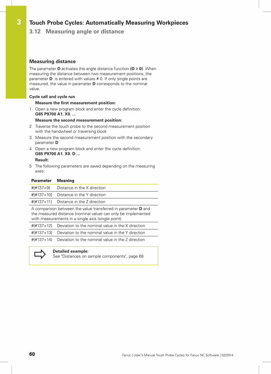
Touch Probe Cycles: Automatically Measuring Workpieces 3.12 Measuring angle or distance
3
60 Fanuc | User’s Manual Touch Probe Cycles for Fanuc NC Software | 02/2014
Measuring distance
The parameter D activates the angle distance function (D ≥ 0). When
measuring the distance between two measurement positions, the
parameter D is entered with values # 0. If only single points are
measured, the value in parameter D corresponds to the nominal
value.
Cycle call and cycle run
Measure the first measurement position:
1 Open a new program block and enter the cycle definition:
G65 P9700 A1. X0. ...
Measure the second measurement position:
2 Traverse the touch probe to the second measurement position
with the handwheel or traversing block
3 Measure the second measurement position with the secondary
parameter D
4 Open a new program block and enter the cycle definition:
G65 P9700 A1. X0. D ...
Result:
5 The following parameters are saved depending on the measuring
axes:
Parameter Meaning
#[#137+9] Distance in the X direction
#[#137+10] Distance in the Y direction
#[#137+11] Distance in the Z direction
A comparison between the value transferred in parameter D and
the measured distance (nominal value) can only be implemented
with measurements in a single axis (single point).
#[#137+12] Deviation to the nominal value in the X direction
#[#137+13] Deviation to the nominal value in the Y direction
#[#137+14] Deviation to the nominal value in the Z direction
Detailed example:
See "Distances on sample components", page 68
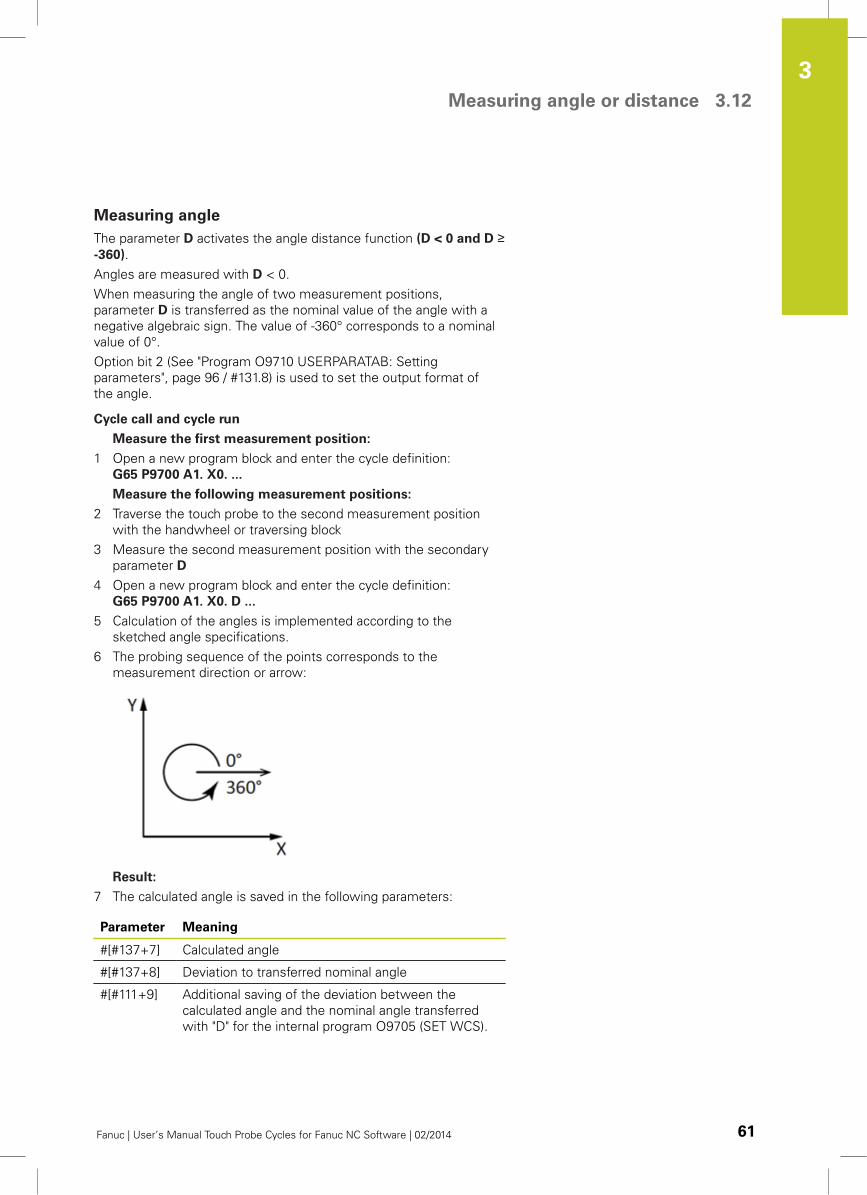
Measuring angle or distance 3.12
3
Fanuc | User’s Manual Touch Probe Cycles for Fanuc NC Software | 02/2014 61
Measuring angle
The parameter D activates the angle distance function (D < 0 and D ≥-360).
Angles are measured with D < 0.
When measuring the angle of two measurement positions,
parameter D is transferred as the nominal value of the angle with a
negative algebraic sign. The value of -360° corresponds to a nominal
value of 0°.
Option bit 2 (See "Program O9710 USERPARATAB: Setting
parameters", page 96 / #131.8) is used to set the output format of
the angle.
Cycle call and cycle run
Measure the first measurement position:
1 Open a new program block and enter the cycle definition:
G65 P9700 A1. X0. ...
Measure the following measurement positions:
2 Traverse the touch probe to the second measurement position
with the handwheel or traversing block
3 Measure the second measurement position with the secondary
parameter D
4 Open a new program block and enter the cycle definition:
G65 P9700 A1. X0. D ...
5 Calculation of the angles is implemented according to the
sketched angle specifications.
6 The probing sequence of the points corresponds to the
measurement direction or arrow:
Result:
7 The calculated angle is saved in the following parameters:
Parameter Meaning
#[#137+7] Calculated angle
#[#137+8] Deviation to transferred nominal angle
#[#111+9] Additional saving of the deviation between the
calculated angle and the nominal angle transferred
with "D" for the internal program O9705 (SET WCS).
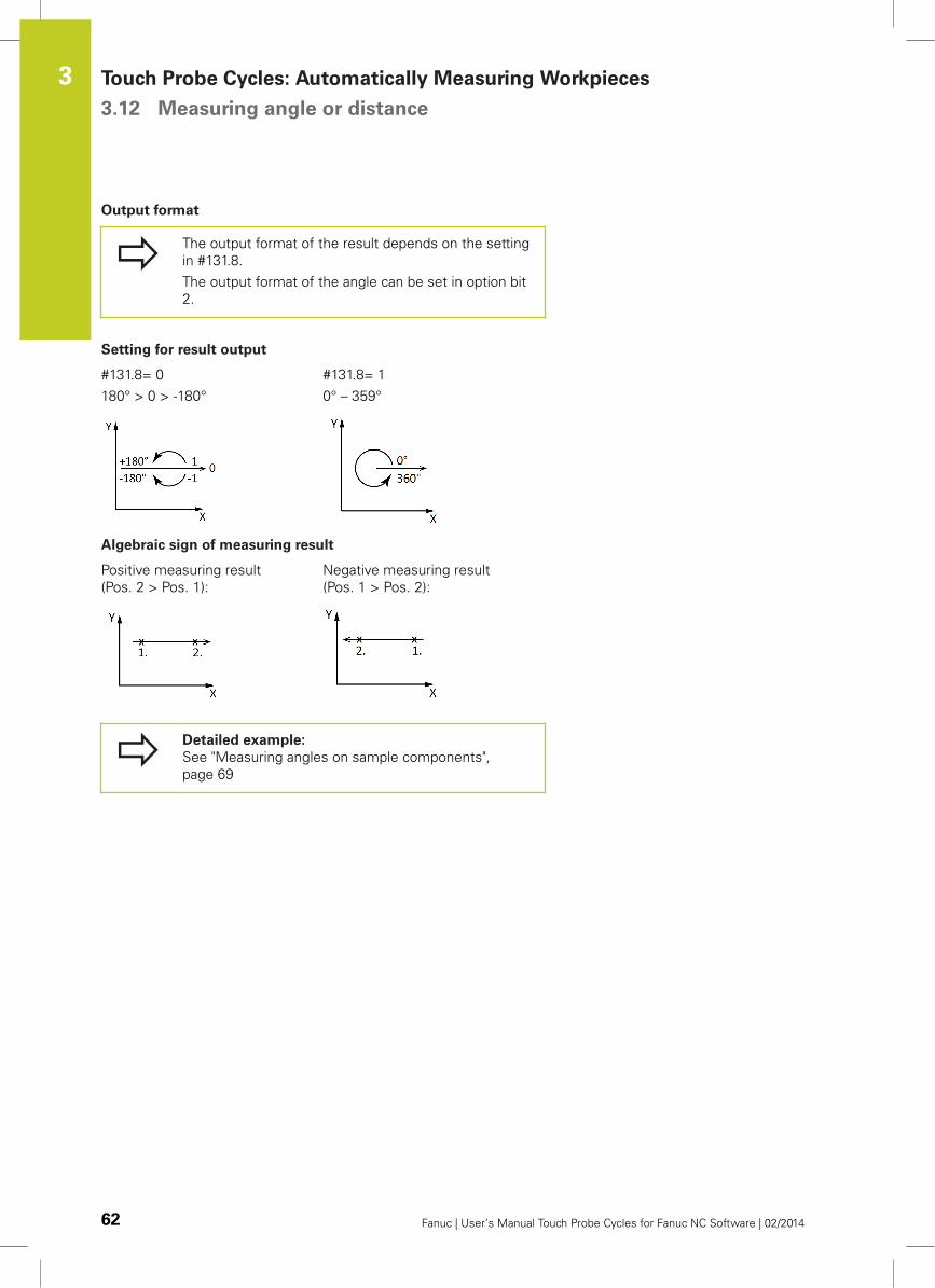
Touch Probe Cycles: Automatically Measuring Workpieces 3.12 Measuring angle or distance
3
62 Fanuc | User’s Manual Touch Probe Cycles for Fanuc NC Software | 02/2014
Output format
The output format of the result depends on the setting
in #131.8.
The output format of the angle can be set in option bit
2.
Setting for result output
#131.8= 0
180° > 0 > -180°
#131.8= 1
0° – 359°
Algebraic sign of measuring result
Positive measuring result
(Pos. 2 > Pos. 1):
Negative measuring result
(Pos. 1 > Pos. 2):
Detailed example:
See "Measuring angles on sample components",
page 69
4Programming
examples
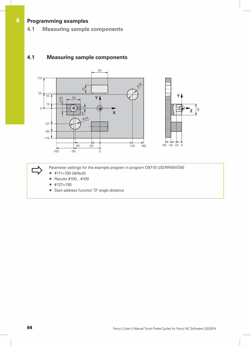
Programming examples 4.1 Measuring sample components
4
64 Fanuc | User’s Manual Touch Probe Cycles for Fanuc NC Software | 02/2014
4.1 Measuring sample components
Parameter settings for the example program in program O9710 USERPARATAB:
#111=100 (default)
Results #100…#109
#137=150
Start address function "D" angle distance
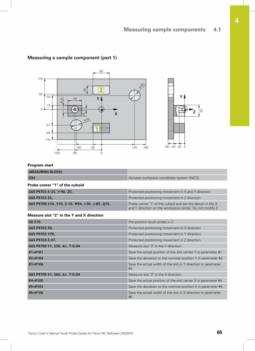
Measuring sample components 4.1
4
Fanuc | User’s Manual Touch Probe Cycles for Fanuc NC Software | 02/2014 65
Measuring a sample component (part 1)
Program start
(MEASURING BLOCK)
G54 Activate workpiece coordinate system (WCS)
Probe corner "1" of the cuboid
G65 P9703 X-35. Y-90. Z5. Protected positioning movement in X and Y direction
G65 P9703 Z5. Protected positioning movement in Z direction
G65 P9700 X10. Y10. Z-10. W54. I-30. J-85 .Q15. Probe corner "1" of the cuboid and set the datum in the X
and Y direction on the workpiece center. Do not modify Z
Measure slot "2" in the Y and X direction
G0 Z10. Pre-position touch probe in Z
G65 P9703 X0. Protected positioning movement in X direction
G65 P9703 Y70. Protected positioning movement in Y direction
G65 P9703 Z-47. Protected positioning movement in Z direction
G65 P9700 Y1. S30. A1. T-0.04 Measure slot "2" in the Y direction
#1=#101 Save the actual position of the slot center Y in parameter #1
#2=#104 Save the deviation to the nominal position Y in parameter #2
#3=#106 Save the actual width of the slot in Y direction in parameter
#3
G65 P9700 X1. S60. A1. T-0.04 Measure slot "2" in the X direction
#4=#100 Save the actual position of the slot center X in parameter #4
#5=#103 Save the deviation to the nominal position X in parameter #5
#6=#106 Save the actual width of the slot in X direction in parameter
#6
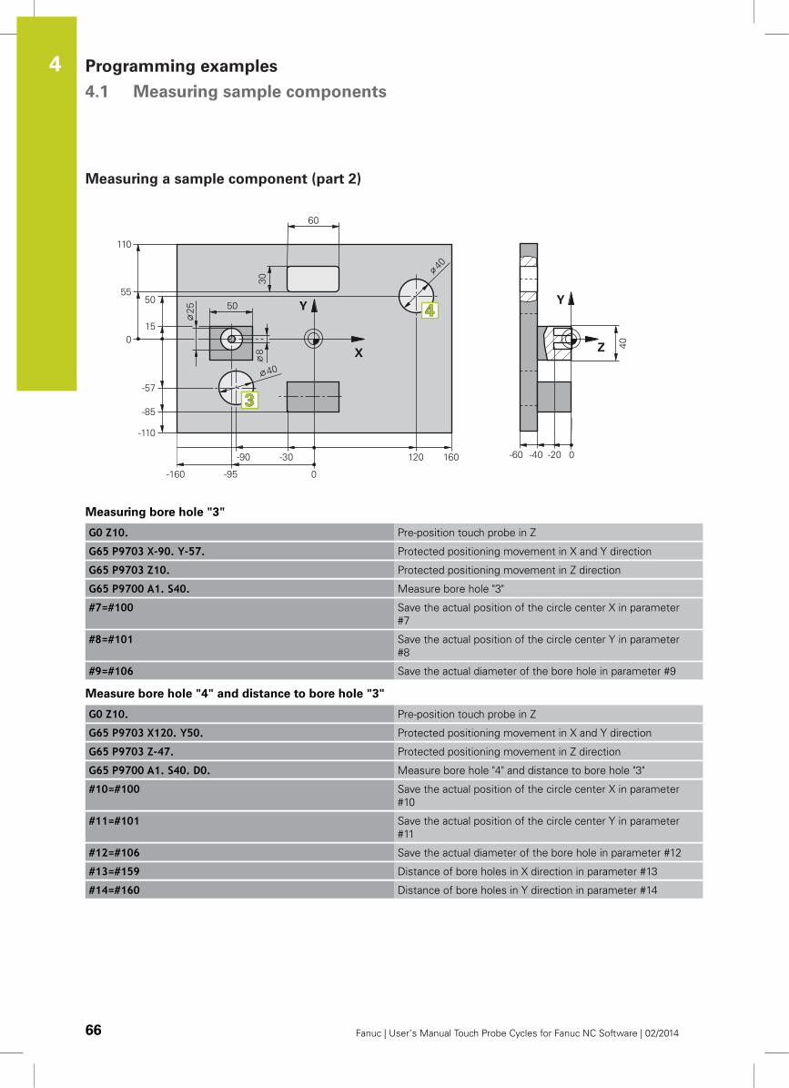
Programming examples 4.1 Measuring sample components
4
66 Fanuc | User’s Manual Touch Probe Cycles for Fanuc NC Software | 02/2014
Measuring a sample component (part 2)
Measuring bore hole "3"
G0 Z10. Pre-position touch probe in Z
G65 P9703 X-90. Y-57. Protected positioning movement in X and Y direction
G65 P9703 Z10. Protected positioning movement in Z direction
G65 P9700 A1. S40. Measure bore hole "3"
#7=#100 Save the actual position of the circle center X in parameter
#7
#8=#101 Save the actual position of the circle center Y in parameter
#8
#9=#106 Save the actual diameter of the bore hole in parameter #9
Measure bore hole "4" and distance to bore hole "3"
G0 Z10. Pre-position touch probe in Z
G65 P9703 X120. Y50. Protected positioning movement in X and Y direction
G65 P9703 Z-47. Protected positioning movement in Z direction
G65 P9700 A1. S40. D0. Measure bore hole "4" and distance to bore hole "3"
#10=#100 Save the actual position of the circle center X in parameter
#10
#11=#101 Save the actual position of the circle center Y in parameter
#11
#12=#106 Save the actual diameter of the bore hole in parameter #12
#13=#159 Distance of bore holes in X direction in parameter #13
#14=#160 Distance of bore holes in Y direction in parameter #14
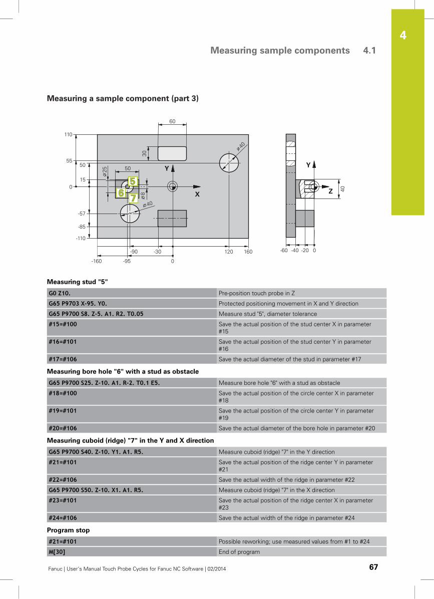
Measuring sample components 4.1
4
Fanuc | User’s Manual Touch Probe Cycles for Fanuc NC Software | 02/2014 67
Measuring a sample component (part 3)
Measuring stud "5"
G0 Z10. Pre-position touch probe in Z
G65 P9703 X-95. Y0. Protected positioning movement in X and Y direction
G65 P9700 S8. Z-5. A1. R2. T0.05 Measure stud "5", diameter tolerance
#15=#100 Save the actual position of the stud center X in parameter
#15
#16=#101 Save the actual position of the stud center Y in parameter
#16
#17=#106 Save the actual diameter of the stud in parameter #17
Measuring bore hole "6" with a stud as obstacle
G65 P9700 S25. Z-10. A1. R-2. T0.1 E5. Measure bore hole "6" with a stud as obstacle
#18=#100 Save the actual position of the circle center X in parameter
#18
#19=#101 Save the actual position of the circle center Y in parameter
#19
#20=#106 Save the actual diameter of the bore hole in parameter #20
Measuring cuboid (ridge) "7" in the Y and X direction
G65 P9700 S40. Z-10. Y1. A1. R5. Measure cuboid (ridge) "7" in the Y direction
#21=#101 Save the actual position of the ridge center Y in parameter
#21
#22=#106 Save the actual width of the ridge in parameter #22
G65 P9700 S50. Z-10. X1. A1. R5. Measure cuboid (ridge) "7" in the X direction
#23=#101 Save the actual position of the ridge center X in parameter
#23
#24=#106 Save the actual width of the ridge in parameter #24
Program stop
#21=#101 Possible reworking; use measured values from #1 to #24
M[30] End of program
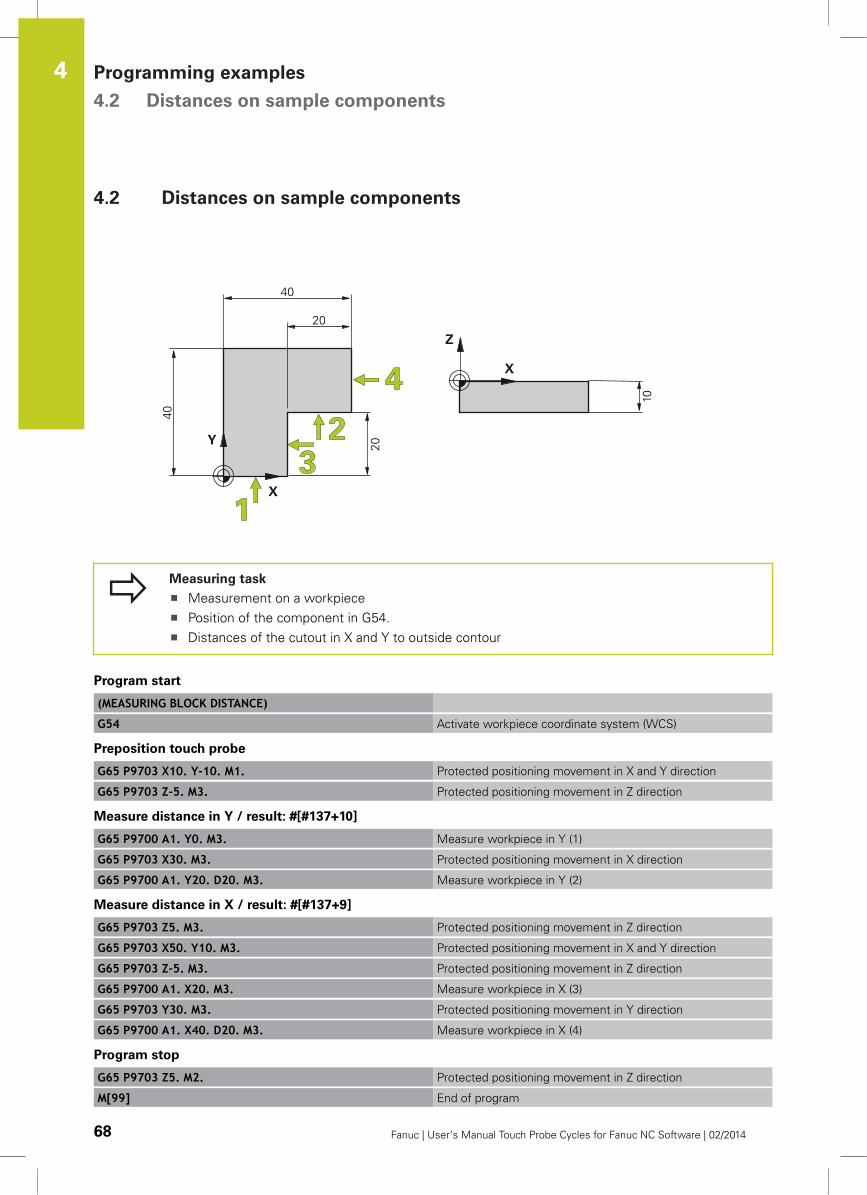
Programming examples 4.2 Distances on sample components
4
68 Fanuc | User’s Manual Touch Probe Cycles for Fanuc NC Software | 02/2014
4.2 Distances on sample components
Measuring task
Measurement on a workpiece
Position of the component in G54.
Distances of the cutout in X and Y to outside contour
Program start
(MEASURING BLOCK DISTANCE)
G54 Activate workpiece coordinate system (WCS)
Preposition touch probe
G65 P9703 X10. Y-10. M1. Protected positioning movement in X and Y direction
G65 P9703 Z-5. M3. Protected positioning movement in Z direction
Measure distance in Y / result: #[#137+10]
G65 P9700 A1. Y0. M3. Measure workpiece in Y (1)
G65 P9703 X30. M3. Protected positioning movement in X direction
G65 P9700 A1. Y20. D20. M3. Measure workpiece in Y (2)
Measure distance in X / result: #[#137+9]
G65 P9703 Z5. M3. Protected positioning movement in Z direction
G65 P9703 X50. Y10. M3. Protected positioning movement in X and Y direction
G65 P9703 Z-5. M3. Protected positioning movement in Z direction
G65 P9700 A1. X20. M3. Measure workpiece in X (3)
G65 P9703 Y30. M3. Protected positioning movement in Y direction
G65 P9700 A1. X40. D20. M3. Measure workpiece in X (4)
Program stop
G65 P9703 Z5. M2. Protected positioning movement in Z direction
M[99] End of program
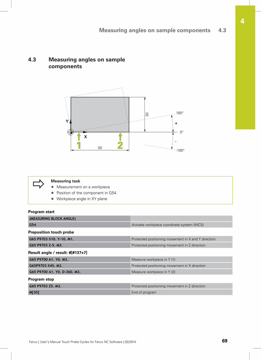
Measuring angles on sample components 4.3
4
Fanuc | User’s Manual Touch Probe Cycles for Fanuc NC Software | 02/2014 69
4.3 Measuring angles on sample
components
Measuring task
Measurement on a workpiece
Position of the component in G54.
Workpiece angle in XY plane
Program start
(MEASURING BLOCK ANGLE)
G54 Activate workpiece coordinate system (WCS)
Preposition touch probe
G65 P9703 X10. Y-10. M1. Protected positioning movement in X and Y direction
G65 P9703 Z-5. M3. Protected positioning movement in Z direction
Result angle / result: #[#137+7]
G65 P9700 A1. Y0. M3. Measure workpiece in Y (1)
G65P9703 X45. M3. Protected positioning movement in X direction
G65 P9700 A1. Y0. D-360. M3. Measure workpiece in Y (2)
Program stop
G65 P9703 Z5. M3. Protected positioning movement in Z direction
M[30] End of program
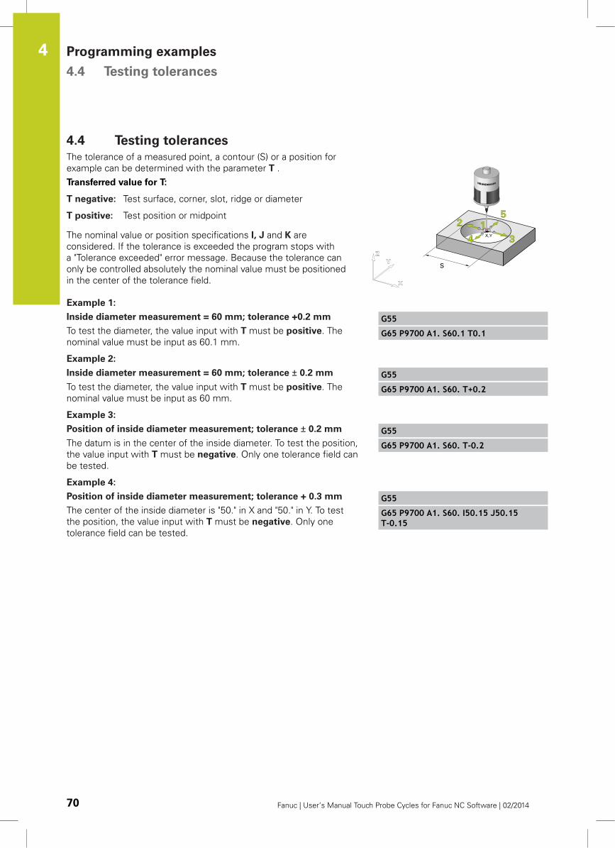
Programming examples 4.4 Testing tolerances
4
70 Fanuc | User’s Manual Touch Probe Cycles for Fanuc NC Software | 02/2014
4.4 Testing tolerances
The tolerance of a measured point, a contour (S) or a position for
example can be determined with the parameter T .
Transferred value for T:
T negative: Test surface, corner, slot, ridge or diameter
T positive: Test position or midpoint
The nominal value or position specifications I, J and K are
considered. If the tolerance is exceeded the program stops with
a "Tolerance exceeded" error message. Because the tolerance can
only be controlled absolutely the nominal value must be positioned
in the center of the tolerance field.
Example 1:
Inside diameter measurement = 60 mm; tolerance +0.2 mm
To test the diameter, the value input with T must be positive. The
nominal value must be input as 60.1 mm.
G55
G65 P9700 A1. S60.1 T0.1
Example 2:
Inside diameter measurement = 60 mm; tolerance ± 0.2 mm
To test the diameter, the value input with T must be positive. The
nominal value must be input as 60 mm.
G55
G65 P9700 A1. S60. T+0.2
Example 3:
Position of inside diameter measurement; tolerance ± 0.2 mm
The datum is in the center of the inside diameter. To test the position,
the value input with T must be negative. Only one tolerance field can
be tested.
G55
G65 P9700 A1. S60. T-0.2
Example 4:
Position of inside diameter measurement; tolerance + 0.3 mm
The center of the inside diameter is "50." in X and "50." in Y. To test
the position, the value input with T must be negative. Only one
tolerance field can be tested.
G55
G65 P9700 A1. S60. I50.15 J50.15T-0.15

5Special cycles
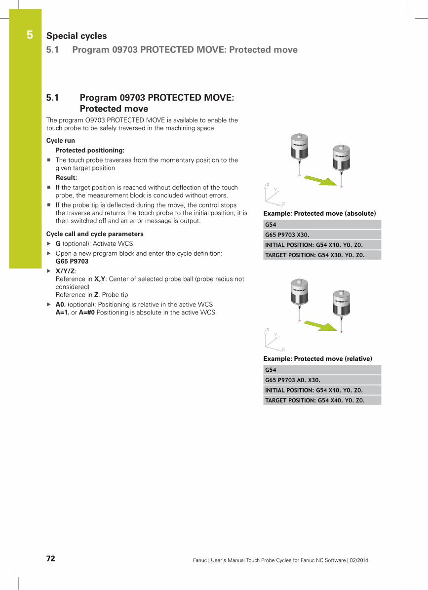
Special cycles 5.1 Program 09703 PROTECTED MOVE: Protected move
5
72 Fanuc | User’s Manual Touch Probe Cycles for Fanuc NC Software | 02/2014
5.1 Program 09703 PROTECTED MOVE:
Protected move
The program O9703 PROTECTED MOVE is available to enable the
touch probe to be safely traversed in the machining space.
Cycle run
Protected positioning:
The touch probe traverses from the momentary position to the
given target position
Result:
If the target position is reached without deflection of the touch
probe, the measurement block is concluded without errors.
If the probe tip is deflected during the move, the control stops
the traverse and returns the touch probe to the initial position; it is
then switched off and an error message is output.
Cycle call and cycle parameters
G (optional): Activate WCS
Open a new program block and enter the cycle definition:
G65 P9703
X/Y/Z:
Reference in X,Y: Center of selected probe ball (probe radius not
considered)
Reference in Z: Probe tip
A0. (optional): Positioning is relative in the active WCS
A=1. or A=#0 Positioning is absolute in the active WCS
Example: Protected move (absolute)
G54
G65 P9703 X30.
INITIAL POSITION: G54 X10. Y0. Z0.
TARGET POSITION: G54 X30. Y0. Z0.
Example: Protected move (relative)
G54
G65 P9703 A0. X30.
INITIAL POSITION: G54 X10. Y0. Z0.
TARGET POSITION: G54 X40. Y0. Z0.
Function G68: Measuring in a Rotated Coordinate System 5.2
5
Fanuc | User’s Manual Touch Probe Cycles for Fanuc NC Software | 02/2014 73
5.2 Function G68: Measuring in a Rotated
Coordinate System
Read the documentation of the control manufacturer.
The "G68" function enables measuring in a rotated coordinate
system, e.g. with small clamping errors of the workpiece in the XY
plane.
The approaches are transferred to the rotated coordinate system.
Skip positions and results are calculated by the software back to the
non-rotated plane.
Measurement precision
The G68 function of the software is intended for
correcting small angles to 5°.
Malfunction
With the G68 command, rotation must be
implemented around the active datum -> G68 X0. Y0.
R…
If coordinate conversion is considered by the control
(e.g. #5400.5 = 1 / LV3), the option bit "#131.1=0" has
to be set.
If the G68 command is active the WCS data cannot be
corrected.
Requirements for installation
The coordinate system rotation function is only available for the
following controls:
FANUC: 0iD, 30i, 31i, 32i, 300i, 310i, 320i
Parameter setting and installation in the program O9710
USERPARATAB
To use the G68 coordinate system rotation function, the option bit
#131.1 has to be set.
Parameter Description
#131.1 Option bit 2
BIT 1
(0): Function G68 not available
(2): Function G68 available
#140 Angle coordinate rotation
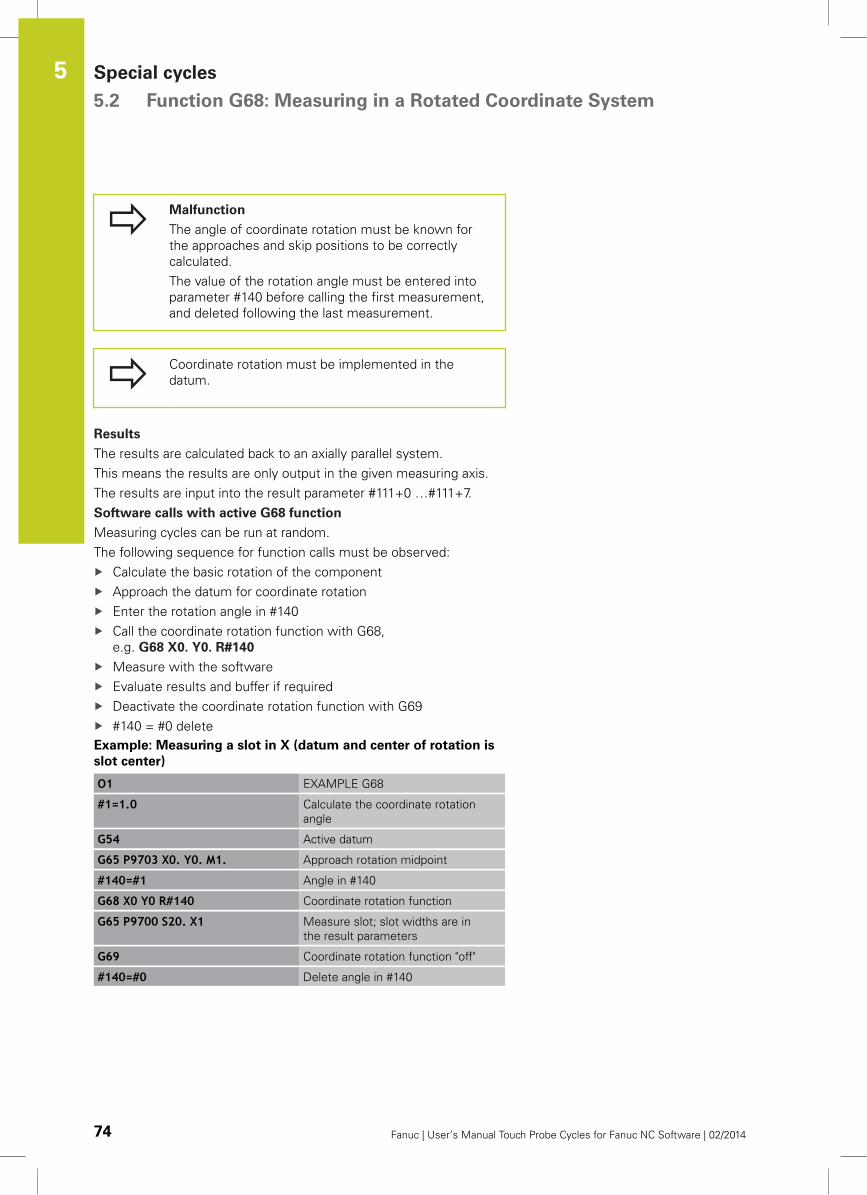
Special cycles 5.2 Function G68: Measuring in a Rotated Coordinate System
5
74 Fanuc | User’s Manual Touch Probe Cycles for Fanuc NC Software | 02/2014
Malfunction
The angle of coordinate rotation must be known for
the approaches and skip positions to be correctly
calculated.
The value of the rotation angle must be entered into
parameter #140 before calling the first measurement,
and deleted following the last measurement.
Coordinate rotation must be implemented in the
datum.
Results
The results are calculated back to an axially parallel system.
This means the results are only output in the given measuring axis.
The results are input into the result parameter #111+0 …#111+7.
Software calls with active G68 function
Measuring cycles can be run at random.
The following sequence for function calls must be observed:
Calculate the basic rotation of the component
Approach the datum for coordinate rotation
Enter the rotation angle in #140
Call the coordinate rotation function with G68,
e.g. G68 X0. Y0. R#140
Measure with the software
Evaluate results and buffer if required
Deactivate the coordinate rotation function with G69
#140 = #0 delete
Example: Measuring a slot in X (datum and center of rotation is
slot center)
O1 EXAMPLE G68
#1=1.0 Calculate the coordinate rotation
angle
G54 Active datum
G65 P9703 X0. Y0. M1. Approach rotation midpoint
#140=#1 Angle in #140
G68 X0 Y0 R#140 Coordinate rotation function
G65 P9700 S20. X1 Measure slot; slot widths are in
the result parameters
G69 Coordinate rotation function "off"
#140=#0 Delete angle in #140
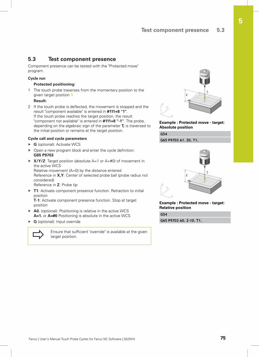
Test component presence 5.3
5
Fanuc | User’s Manual Touch Probe Cycles for Fanuc NC Software | 02/2014 75
5.3 Test component presence
Component presence can be tested with the "Protected move"
program.
Cycle run
Protected positioning:
1 The touch probe traverses from the momentary position to the
given target position 1
Result:
2 If the touch probe is deflected, the movement is stopped and the
result "component available" is entered in #111+8 "1".
If the touch probe reaches the target position, the result
"component not available" is entered in #111+8 "-1". The probe,
depending on the algebraic sign of the parameter T, is traversed to
the initial position or remains at the target position.
Cycle call and cycle parameters
G (optional): Activate WCS
Open a new program block and enter the cycle definition:
G65 P9703
X/Y/Z: Target position (absolute A=1 or A=#0) of movement in
the active WCS
Relative movement (A=0) by the distance entered
Reference in X,Y: Center of selected probe ball (probe radius not
considered)
Reference in Z: Probe tip
T1: Activate component presence function. Retraction to initial
position
T-1: Activate component presence function. Stop at target
position
A0. (optional): Positioning is relative in the active WCS
A=1. or A=#0 Positioning is absolute in the active WCS
Q (optional): Input override
Ensure that sufficient "override" is available at the given
target position.
Example : Protected move - target:
Absolute position
G54
G65 P9703 A1. Z0. T1.
Example : Protected move - target:
Relative position
G54
G65 P9703 A0. Z-10. T1.

6Calibrating aTouch Trigger
Probe
Calibrating a Touch Trigger Probe 6.1 Calibrating a touch trigger probe
6
78 Fanuc | User’s Manual Touch Probe Cycles for Fanuc NC Software | 02/2014
6.1 Calibrating a touch trigger probe
Why calibrate?
The stylus of the touch probe approaches the workpiece during
the probe process. As soon as the stylus is deflected by the
workpiece, the machine stops the movement and saves the
momentary spindle position in special control parameters. The
saves spindle position however does not precisely correspond to
the position of the measured workpiece edge.
Reasons for deviations:
Time delay of the control
Ball tip radius
Center misalignment of ball tip
When to calibrate
Always calibrate the touch probe with:
Commissioning
Stylus breakage
Stylus exchange
Modification of parameters for measurement speed (#126,
#127) in the program O9710 USERPARATAB
Irregularities caused, for example, when the machine heats up
Very precise measurements
Changing the unit of measurement from metric to inch
dimensions and vice versa
How to calibrate
To ensure that the control supplies precise measurement results,
the actual trigger of a touch probe must be determined by
calibration.
The control measures the following calibration values:
Function Calibration values Page
Measuring touch probe
length with the ring gauge
Calibration value
Z axis
page 80
Measuring touch probe
radius and center
misalignment with the
ring gauge
Calibration value
X axis / Y axis
Center
misalignment
X axis / Y axis
page 81
Measuring touch probe
radius and center
misalignment with the
calibration sphere
Calibration value
X axis / Y axis
Center
misalignment
X axis / Y axis
page 83
For calibration in Z, the software requires a surface in the XY
plane precisely known in the Z position.
For calibration in X and Y, a ring gauge or calibration sphere is
required with precisely defined diameter.
Calibrating a touch trigger probe 6.1
6
Fanuc | User’s Manual Touch Probe Cycles for Fanuc NC Software | 02/2014 79
The calibration is called via the program 09700 MAIN . Selecting
calibration is implemented by transferring the corresponding
parameters.
Calibrating the touch probe in the X and Y axes is
carried out separately from calibration of the Z axis.
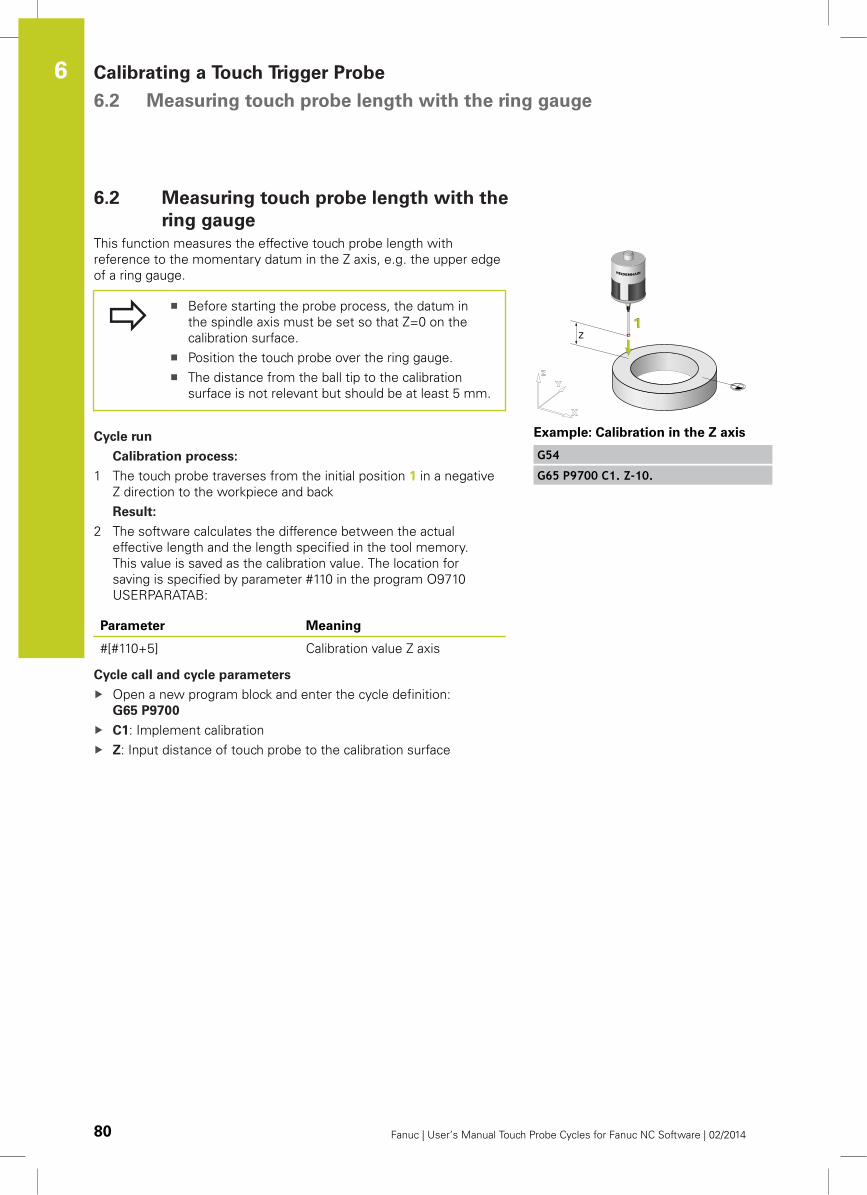
Calibrating a Touch Trigger Probe 6.2 Measuring touch probe length with the ring gauge
6
80 Fanuc | User’s Manual Touch Probe Cycles for Fanuc NC Software | 02/2014
6.2 Measuring touch probe length with the
ring gauge
This function measures the effective touch probe length with
reference to the momentary datum in the Z axis, e.g. the upper edge
of a ring gauge.
Before starting the probe process, the datum in
the spindle axis must be set so that Z=0 on the
calibration surface.
Position the touch probe over the ring gauge.
The distance from the ball tip to the calibration
surface is not relevant but should be at least 5 mm.
Cycle run
Calibration process:
1 The touch probe traverses from the initial position 1 in a negative
Z direction to the workpiece and back
Result:
2 The software calculates the difference between the actual
effective length and the length specified in the tool memory.
This value is saved as the calibration value. The location for
saving is specified by parameter #110 in the program O9710
USERPARATAB:
Parameter Meaning
#[#110+5] Calibration value Z axis
Cycle call and cycle parameters
Open a new program block and enter the cycle definition:
G65 P9700
C1: Implement calibration
Z: Input distance of touch probe to the calibration surface
Example: Calibration in the Z axis
G54
G65 P9700 C1. Z-10.
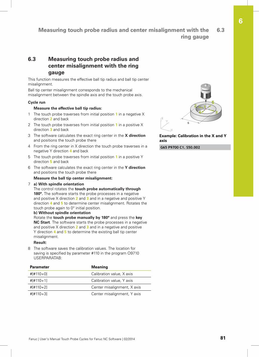
Measuring touch probe radius and center misalignment with the
ring gauge
6.3
6
Fanuc | User’s Manual Touch Probe Cycles for Fanuc NC Software | 02/2014 81
6.3 Measuring touch probe radius and
center misalignment with the ring
gauge
This function measures the effective ball tip radius and ball tip center
misalignment.
Ball tip center misalignment corresponds to the mechanical
misalignment between the spindle axis and the touch probe axis.
Cycle run
Measure the effective ball tip radius:
1 The touch probe traverses from initial position 1 in a negative X
direction 2 and back
2 The touch probe traverses from initial position 1 in a positive X
direction 3 and back
3 The software calculates the exact ring center in the X direction
and positions the touch probe there
4 From the ring center in X direction the touch probe traverses in a
negative Y direction 4 and back
5 The touch probe traverses from initial position 1 in a positive Y
direction 5 and back
6 The software calculates the exact ring center in the Y direction
and positions the touch probe there
Measure the ball tip center misalignment:
7 a) With spindle orientation
The control rotates the touch probe automatically through
180°. The software starts the probe processes in a negative
and positive X direction 2 and 3 and in a negative and positive Y
direction 4 and 5 to determine center misalignment. Rotates the
touch probe again to 0° initial position.
b) Without spindle orientation
Rotate the touch probe manually by 180° and press the key
NC Start. The software starts the probe processes in a negative
and positive X direction 2 and 3 and in a negative and positive
Y direction 4 and 5 to determine the existing ball tip center
misalignment.
Result:
8 The software saves the calibration values. The location for
saving is specified by parameter #110 in the program O9710
USERPARATAB:
Parameter Meaning
#[#110+0] Calibration value, X axis
#[#110+1] Calibration value, Y axis
#[#110+2] Center misalignment, X axis
#[#110+3] Center misalignment, Y axis
Example: Calibration in the X and Y
axis
G65 P9700 C1. S50.002
Calibrating a Touch Trigger Probe 6.3 Measuring touch probe radius and center misalignment with the
ring gauge
6
82 Fanuc | User’s Manual Touch Probe Cycles for Fanuc NC Software | 02/2014
During calibration the touch probe is oriented
automatically or manually depending on the settings
in option bit #130.
Calibration can also be carried out on an outside
diameter. The optional parameter Z is used for this.
Cycle call and cycle parameters
Open a new program block and enter the cycle definition:
G65 P9700
C1: Implement calibration
S: Input the exact diameter of the ring gauge
Z (optional): Input distance of touch probe to the calibration
surface
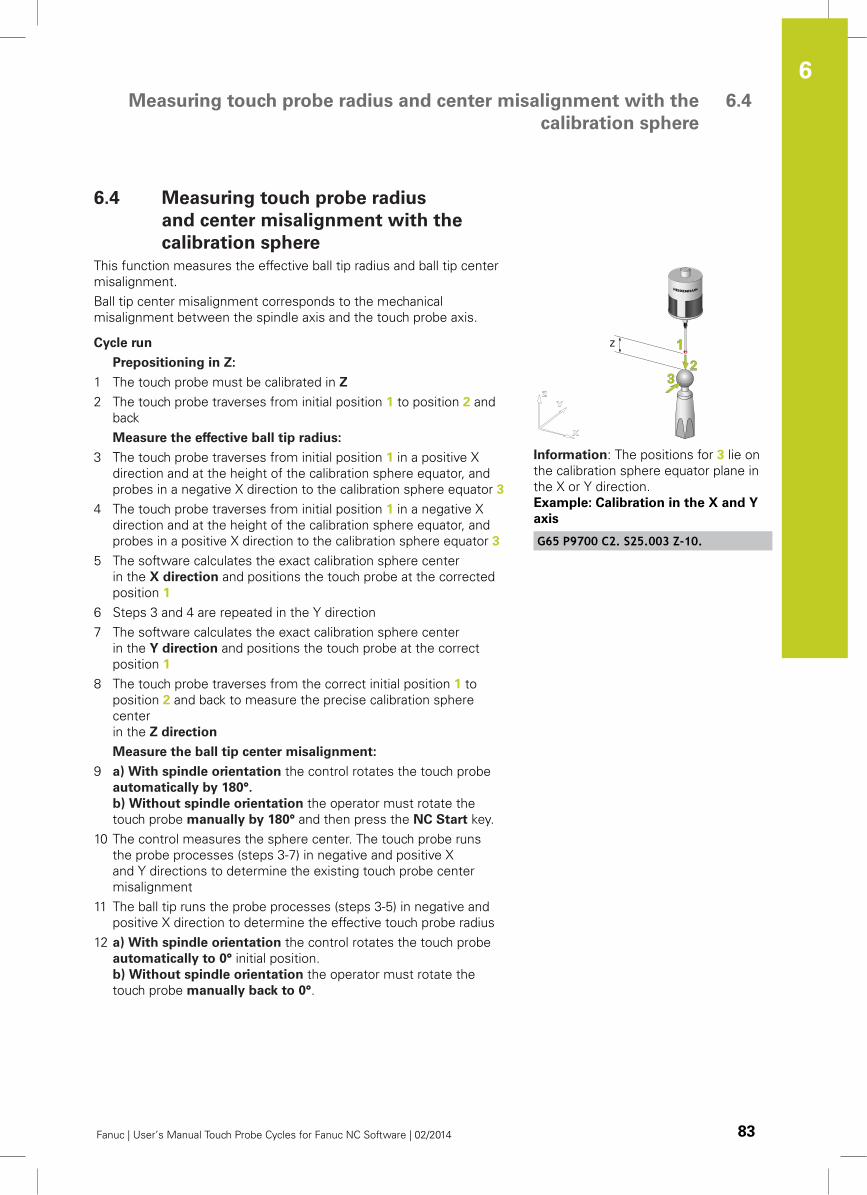
Measuring touch probe radius and center misalignment with the
calibration sphere
6.4
6
Fanuc | User’s Manual Touch Probe Cycles for Fanuc NC Software | 02/2014 83
6.4 Measuring touch probe radius
and center misalignment with the
calibration sphere
This function measures the effective ball tip radius and ball tip center
misalignment.
Ball tip center misalignment corresponds to the mechanical
misalignment between the spindle axis and the touch probe axis.
Cycle run
Prepositioning in Z:
1 The touch probe must be calibrated in Z
2 The touch probe traverses from initial position 1 to position 2 and
back
Measure the effective ball tip radius:
3 The touch probe traverses from initial position 1 in a positive X
direction and at the height of the calibration sphere equator, and
probes in a negative X direction to the calibration sphere equator 3
4 The touch probe traverses from initial position 1 in a negative X
direction and at the height of the calibration sphere equator, and
probes in a positive X direction to the calibration sphere equator 3
5 The software calculates the exact calibration sphere center
in the X direction and positions the touch probe at the corrected
position 1
6 Steps 3 and 4 are repeated in the Y direction
7 The software calculates the exact calibration sphere center
in the Y direction and positions the touch probe at the correct
position 1
8 The touch probe traverses from the correct initial position 1 to
position 2 and back to measure the precise calibration sphere
center
in the Z direction
Measure the ball tip center misalignment:
9 a) With spindle orientation the control rotates the touch probe
automatically by 180°.
b) Without spindle orientation the operator must rotate the
touch probe manually by 180° and then press the NC Start key.
10 The control measures the sphere center. The touch probe runs
the probe processes (steps 3-7) in negative and positive X
and Y directions to determine the existing touch probe center
misalignment
11 The ball tip runs the probe processes (steps 3-5) in negative and
positive X direction to determine the effective touch probe radius
12 a) With spindle orientation the control rotates the touch probe
automatically to 0° initial position.
b) Without spindle orientation the operator must rotate the
touch probe manually back to 0°.
Information: The positions for 3 lie on
the calibration sphere equator plane in
the X or Y direction.
Example: Calibration in the X and Y
axis
G65 P9700 C2. S25.003 Z-10.
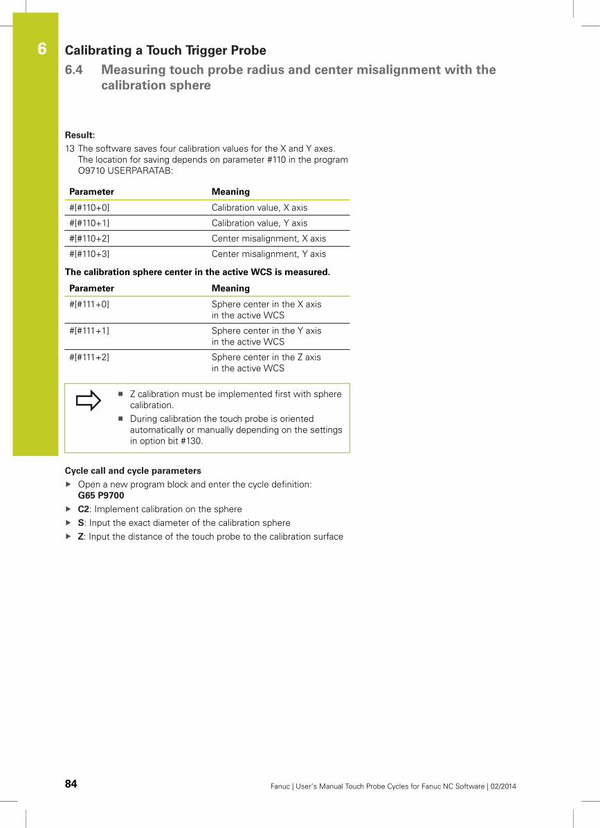
Calibrating a Touch Trigger Probe 6.4 Measuring touch probe radius and center misalignment with the
calibration sphere
6
84 Fanuc | User’s Manual Touch Probe Cycles for Fanuc NC Software | 02/2014
Result:
13 The software saves four calibration values for the X and Y axes.
The location for saving depends on parameter #110 in the program
O9710 USERPARATAB:
Parameter Meaning
#[#110+0] Calibration value, X axis
#[#110+1] Calibration value, Y axis
#[#110+2] Center misalignment, X axis
#[#110+3] Center misalignment, Y axis
The calibration sphere center in the active WCS is measured.
Parameter Meaning
#[#111+0] Sphere center in the X axis
in the active WCS
#[#111+1] Sphere center in the Y axis
in the active WCS
#[#111+2] Sphere center in the Z axis
in the active WCS
Z calibration must be implemented first with sphere
calibration.
During calibration the touch probe is oriented
automatically or manually depending on the settings
in option bit #130.
Cycle call and cycle parameters
Open a new program block and enter the cycle definition:
G65 P9700
C2: Implement calibration on the sphere
S: Input the exact diameter of the calibration sphere
Z: Input the distance of the touch probe to the calibration surface

7Parameter tables
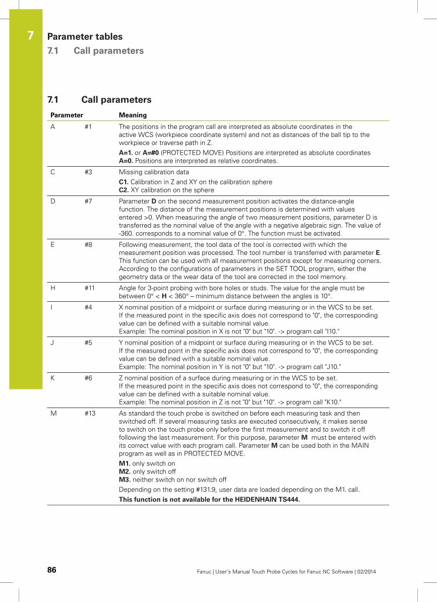
Parameter tables 7.1 Call parameters
7
86 Fanuc | User’s Manual Touch Probe Cycles for Fanuc NC Software | 02/2014
7.1 Call parameters
Parameter Meaning
A #1 The positions in the program call are interpreted as absolute coordinates in the
active WCS (workpiece coordinate system) and not as distances of the ball tip to the
workpiece or traverse path in Z.
A=1. or A=#0 (PROTECTED MOVE) Positions are interpreted as absolute coordinates
A=0. Positions are interpreted as relative coordinates.
C #3 Missing calibration data
C1. Calibration in Z and XY on the calibration sphere
C2. XY calibration on the sphere
D #7 Parameter D on the second measurement position activates the distance-angle
function. The distance of the measurement positions is determined with values
entered >0. When measuring the angle of two measurement positions, parameter D is
transferred as the nominal value of the angle with a negative algebraic sign. The value of
-360. corresponds to a nominal value of 0°. The function must be activated.
E #8 Following measurement, the tool data of the tool is corrected with which the
measurement position was processed. The tool number is transferred with parameter E.
This function can be used with all measurement positions except for measuring corners.
According to the configurations of parameters in the SET TOOL program, either the
geometry data or the wear data of the tool are corrected in the tool memory.
H #11 Angle for 3-point probing with bore holes or studs. The value for the angle must be
between 0° < H < 360° – minimum distance between the angles is 10°.
I #4 X nominal position of a midpoint or surface during measuring or in the WCS to be set.
If the measured point in the specific axis does not correspond to "0", the corresponding
value can be defined with a suitable nominal value.
Example: The nominal position in X is not "0" but "10". -> program call "I10."
J #5 Y nominal position of a midpoint or surface during measuring or in the WCS to be set.
If the measured point in the specific axis does not correspond to "0", the corresponding
value can be defined with a suitable nominal value.
Example: The nominal position in Y is not "0" but "10". -> program call "J10."
K #6 Z nominal position of a surface during measuring or in the WCS to be set.
If the measured point in the specific axis does not correspond to "0", the corresponding
value can be defined with a suitable nominal value.
Example: The nominal position in Z is not "0" but "10". -> program call "K10."
M #13 As standard the touch probe is switched on before each measuring task and then
switched off. If several measuring tasks are executed consecutively, it makes sense
to switch on the touch probe only before the first measurement and to switch it off
following the last measurement. For this purpose, parameter M must be entered with
its correct value with each program call. Parameter M can be used both in the MAIN
program as well as in PROTECTED MOVE.
M1. only switch on
M2. only switch off
M3. neither switch on nor switch off
Depending on the setting #131.9, user data are loaded depending on the M1. call.
This function is not available for the HEIDENHAIN TS444.
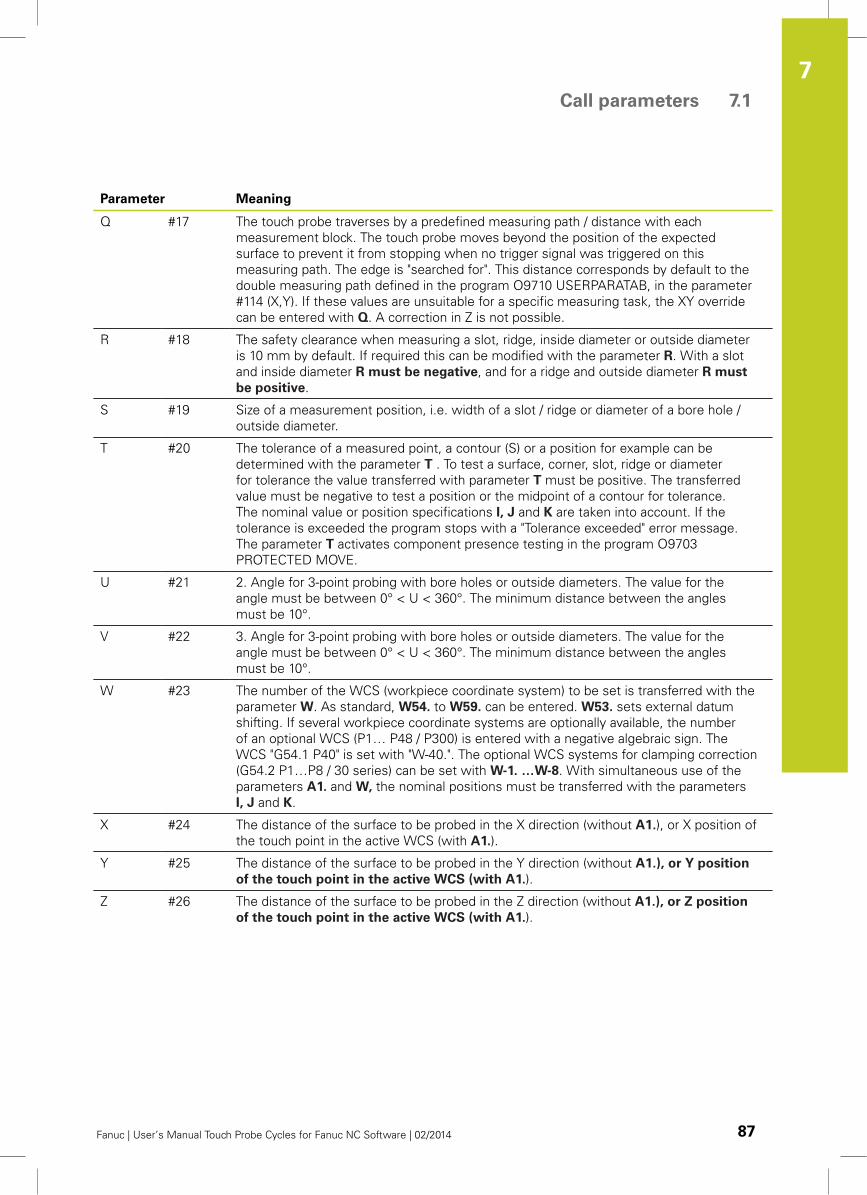
Call parameters 7.1
7
Fanuc | User’s Manual Touch Probe Cycles for Fanuc NC Software | 02/2014 87
Parameter Meaning
Q #17 The touch probe traverses by a predefined measuring path / distance with each
measurement block. The touch probe moves beyond the position of the expected
surface to prevent it from stopping when no trigger signal was triggered on this
measuring path. The edge is "searched for". This distance corresponds by default to the
double measuring path defined in the program O9710 USERPARATAB, in the parameter
#114 (X,Y). If these values are unsuitable for a specific measuring task, the XY override
can be entered with Q. A correction in Z is not possible.
R #18 The safety clearance when measuring a slot, ridge, inside diameter or outside diameter
is 10 mm by default. If required this can be modified with the parameter R. With a slot
and inside diameter R must be negative, and for a ridge and outside diameter R must
be positive.
S #19 Size of a measurement position, i.e. width of a slot / ridge or diameter of a bore hole /
outside diameter.
T #20 The tolerance of a measured point, a contour (S) or a position for example can be
determined with the parameter T . To test a surface, corner, slot, ridge or diameter
for tolerance the value transferred with parameter T must be positive. The transferred
value must be negative to test a position or the midpoint of a contour for tolerance.
The nominal value or position specifications I, J and K are taken into account. If the
tolerance is exceeded the program stops with a "Tolerance exceeded" error message.
The parameter T activates component presence testing in the program O9703
PROTECTED MOVE.
U #21 2. Angle for 3-point probing with bore holes or outside diameters. The value for the
angle must be between 0° < U < 360°. The minimum distance between the angles
must be 10°.
V #22 3. Angle for 3-point probing with bore holes or outside diameters. The value for the
angle must be between 0° < U < 360°. The minimum distance between the angles
must be 10°.
W #23 The number of the WCS (workpiece coordinate system) to be set is transferred with the
parameter W. As standard, W54. to W59. can be entered. W53. sets external datum
shifting. If several workpiece coordinate systems are optionally available, the number
of an optional WCS (P1… P48 / P300) is entered with a negative algebraic sign. The
WCS "G54.1 P40" is set with "W-40.". The optional WCS systems for clamping correction
(G54.2 P1…P8 / 30 series) can be set with W-1. …W-8. With simultaneous use of the
parameters A1. and W, the nominal positions must be transferred with the parameters
I, J and K.
X #24 The distance of the surface to be probed in the X direction (without A1.), or X position of
the touch point in the active WCS (with A1.).
Y #25 The distance of the surface to be probed in the Y direction (without A1.), or Y position
of the touch point in the active WCS (with A1.).
Z #26 The distance of the surface to be probed in the Z direction (without A1.), or Z position
of the touch point in the active WCS (with A1.).
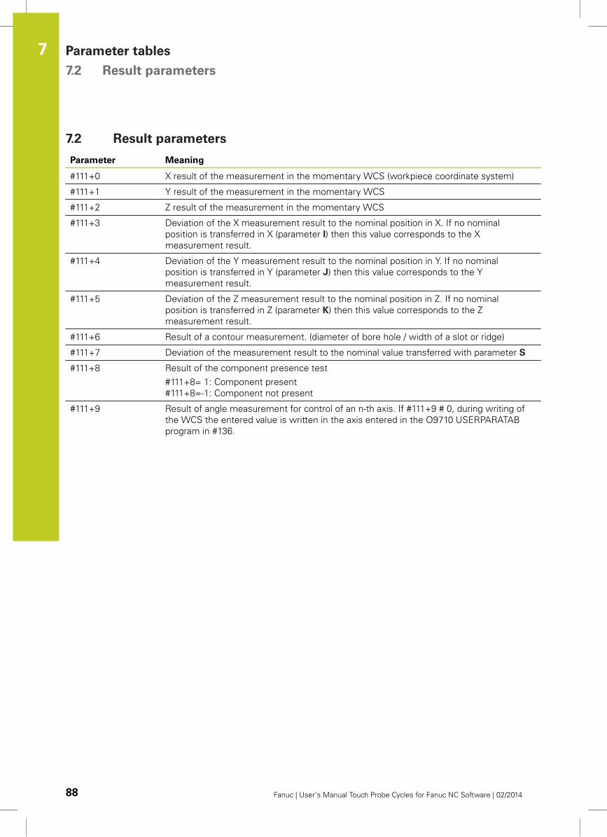
Parameter tables 7.2 Result parameters
7
88 Fanuc | User’s Manual Touch Probe Cycles for Fanuc NC Software | 02/2014
7.2 Result parameters
Parameter Meaning
#111+0 X result of the measurement in the momentary WCS (workpiece coordinate system)
#111+1 Y result of the measurement in the momentary WCS
#111+2 Z result of the measurement in the momentary WCS
#111+3 Deviation of the X measurement result to the nominal position in X. If no nominal
position is transferred in X (parameter I) then this value corresponds to the X
measurement result.
#111+4 Deviation of the Y measurement result to the nominal position in Y. If no nominal
position is transferred in Y (parameter J) then this value corresponds to the Y
measurement result.
#111+5 Deviation of the Z measurement result to the nominal position in Z. If no nominal
position is transferred in Z (parameter K) then this value corresponds to the Z
measurement result.
#111+6 Result of a contour measurement. (diameter of bore hole / width of a slot or ridge)
#111+7 Deviation of the measurement result to the nominal value transferred with parameter S
#111+8 Result of the component presence test
#111+8= 1: Component present
#111+8=-1: Component not present
#111+9 Result of angle measurement for control of an n-th axis. If #111+9 # 0, during writing of
the WCS the entered value is written in the axis entered in the O9710 USERPARATAB
program in #136.
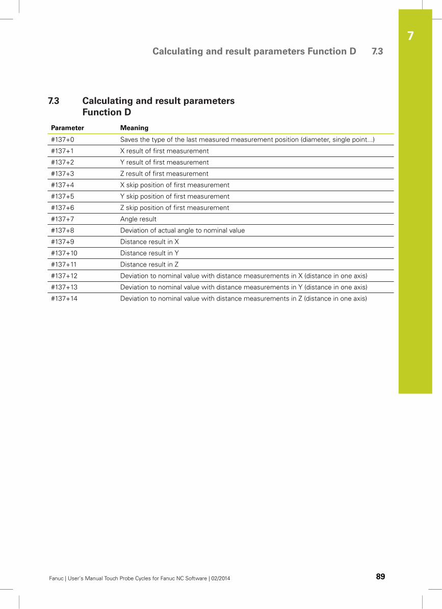
Calculating and result parameters Function D 7.3
7
Fanuc | User’s Manual Touch Probe Cycles for Fanuc NC Software | 02/2014 89
7.3 Calculating and result parameters
Function D
Parameter Meaning
#137+0 Saves the type of the last measured measurement position (diameter, single point...)
#137+1 X result of first measurement
#137+2 Y result of first measurement
#137+3 Z result of first measurement
#137+4 X skip position of first measurement
#137+5 Y skip position of first measurement
#137+6 Z skip position of first measurement
#137+7 Angle result
#137+8 Deviation of actual angle to nominal value
#137+9 Distance result in X
#137+10 Distance result in Y
#137+11 Distance result in Z
#137+12 Deviation to nominal value with distance measurements in X (distance in one axis)
#137+13 Deviation to nominal value with distance measurements in Y (distance in one axis)
#137+14 Deviation to nominal value with distance measurements in Z (distance in one axis)
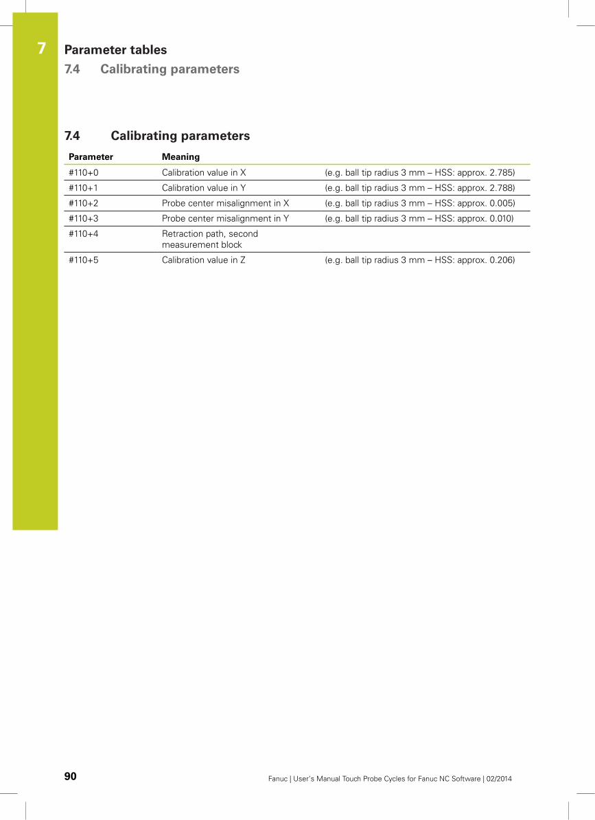
Parameter tables 7.4 Calibrating parameters
7
90 Fanuc | User’s Manual Touch Probe Cycles for Fanuc NC Software | 02/2014
7.4 Calibrating parameters
Parameter Meaning
#110+0 Calibration value in X (e.g. ball tip radius 3 mm – HSS: approx. 2.785)
#110+1 Calibration value in Y (e.g. ball tip radius 3 mm – HSS: approx. 2.788)
#110+2 Probe center misalignment in X (e.g. ball tip radius 3 mm – HSS: approx. 0.005)
#110+3 Probe center misalignment in Y (e.g. ball tip radius 3 mm – HSS: approx. 0.010)
#110+4 Retraction path, second
measurement block
#110+5 Calibration value in Z (e.g. ball tip radius 3 mm – HSS: approx. 0.206)
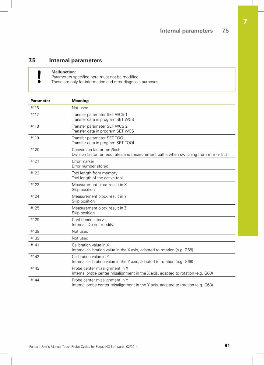
Internal parameters 7.5
7
Fanuc | User’s Manual Touch Probe Cycles for Fanuc NC Software | 02/2014 91
7.5 Internal parameters
Malfunction:
Parameters specified here must not be modified.
These are only for information and error diagnosis purposes.
Parameter Meaning
#116 Not used
#117 Transfer parameter SET WCS 1
Transfer data in program SET WCS
#118 Transfer parameter SET WCS 2
Transfer data in program SET WCS
#119 Transfer parameter SET TOOL
Transfer data in program SET TOOL
#120 Conversion factor mm/Inch
Division factor for feed rates and measurement paths when switching from mm -> Inch
#121 Error marker
Error number stored
#122 Tool length from memory
Tool length of the active tool
#123 Measurement block result in X
Skip position
#124 Measurement block result in Y
Skip position
#125 Measurement block result in Z
Skip position
#129 Confidence interval
Internal: Do not modify.
#138 Not used
#139 Not used
#141 Calibration value in X
Internal calibration value in the X axis, adapted to rotation (e.g. G68)
#142 Calibration value in Y
Internal calibration value in the Y axis, adapted to rotation (e.g. G68)
#143 Probe center misalignment in X
Internal probe center misalignment in the X axis, adapted to rotation (e.g. G68)
#144 Probe center misalignment in Y
Internal probe center misalignment in the Y axis, adapted to rotation (e.g. G68)

8Software
installation
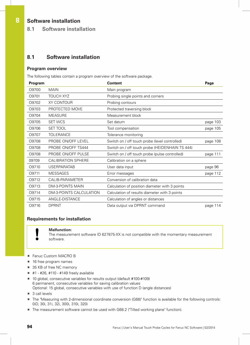
Software installation 8.1 Software installation
8
94 Fanuc | User’s Manual Touch Probe Cycles for Fanuc NC Software | 02/2014
8.1 Software installation
Program overview
The following tables contain a program overview of the software package.
Program Content Page
O9700 MAIN Main program
O9701 TOUCH XYZ Probing single points and corners
O9702 XY CONTOUR Probing contours
O9703 PROTECTED MOVE Protected traversing block
O9704 MEASURE Measurement block
O9705 SET WCS Set datum page 103
O9706 SET TOOL Tool compensation page 105
O9707 TOLERANCE Tolerance monitoring
O9708 PROBE ON/OFF LEVEL Switch on / off touch probe (level controlled) page 108
O9708 PROBE ON/OFF TS444 Switch on / off touch probe (HEIDENHAIN TS 444)
O9708 PROBE ON/OFF PULSE Switch on / off touch probe (pulse controlled) page 111
09709 CALIBRATION SPHERE Calibration on a sphere
O9710 USERPARATAB User data input page 96
O9711 MESSAGES Error messages page 112
O9712 CALIB-PARAMETER Conversion of calibration data
O9713 DM-3-POINTS MAIN Calculation of position diameter with 3 points
O9714 DM-3-POINTS CALCULATION Calculation of results diameter with 3 points
O9715 ANGLE-DISTANCE Calculation of angles or distances
O9716 DPRNT Data output via DPRNT command page 114
Requirements for installation
Malfunction:
The measurement software ID 627875-XX is not compatible with the momentary measurement
software.
Fanuc Custom MACRO B
16 free program names
35 KB of free NC memory
#1 - #26, #110 - #149 freely available
10 global, consecutive variables for results output (default #100-#109)
6 permanent, consecutive variables for saving calibration values
Optional: 15 global, consecutive variables with use of function D (angle distances)
3 call levels
The "Measuring with 2-dimensional coordinate conversion (G68)" function is available for the following controls:
0iD, 30i, 31i, 32i, 300i, 310i, 320i
The measurement software cannot be used with G68.2 ("Tilted working plane" function).
Software installation 8.1
8
Fanuc | User’s Manual Touch Probe Cycles for Fanuc NC Software | 02/2014 95
Recommended:
High speed skip
2 PLC inputs for error monitoring (readiness, battery warning)
Installing hardware
Read the installation instructions of the touch probe used.
Installing and testing software
Transfer all programs in the installation package to the control
FANUC measurement software:
Package with programs that cannot be modified by the user:
9700-9707, 9709, 9711-9716
User programs:
Programs that must be modified by the user:
9708, 9710
Modify program O9710 USERPARATAB (See page 96)
Modify program O9708 PROBE ON/OFF (See page 111)
Enter the precise touch probe length into the tool table of the machine.
Before commissioning
Before commissioning, check whether the used parameters and software areas are already being
used.
If this is the case, cycles must be adapted, as the overwriting of parameters and data used may
cause unforeseeable damage to the machine.
After completion of commissioning, parameters used and executed machine-specific program
modifications must be documented.
Testing measurement cycles
Measurement cycles should be interpreted as examples for solving measurement tasks and
must be modified by machine manufacturers or users to the specific type of machine.
When commissioning the measurement cycles the program must be tested blockwise under
observance of all safety measures (block testing prior to execution, single block and reduced feed
rate).
Write protection must be canceled to load and modify the measurement programs: Parameter
3202 bit 4 (NE9) = 0: Write protection for programs O9xxx inactive
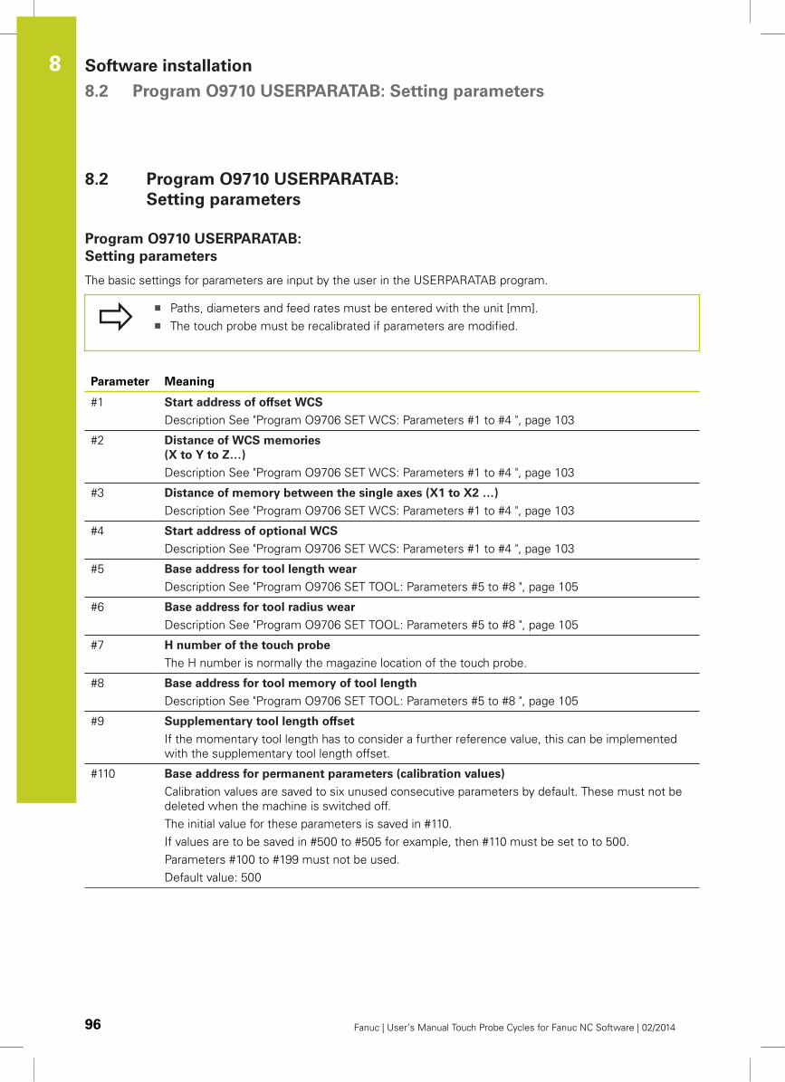
Software installation 8.2 Program O9710 USERPARATAB: Setting parameters
8
96 Fanuc | User’s Manual Touch Probe Cycles for Fanuc NC Software | 02/2014
8.2 Program O9710 USERPARATAB:
Setting parameters
Program O9710 USERPARATAB:
Setting parameters
The basic settings for parameters are input by the user in the USERPARATAB program.
Paths, diameters and feed rates must be entered with the unit [mm].
The touch probe must be recalibrated if parameters are modified.
Parameter Meaning
#1 Start address of offset WCS
Description See "Program O9706 SET WCS: Parameters #1 to #4 ", page 103
#2 Distance of WCS memories
(X to Y to Z…)
Description See "Program O9706 SET WCS: Parameters #1 to #4 ", page 103
#3 Distance of memory between the single axes (X1 to X2 …)
Description See "Program O9706 SET WCS: Parameters #1 to #4 ", page 103
#4 Start address of optional WCS
Description See "Program O9706 SET WCS: Parameters #1 to #4 ", page 103
#5 Base address for tool length wear
Description See "Program O9706 SET TOOL: Parameters #5 to #8 ", page 105
#6 Base address for tool radius wear
Description See "Program O9706 SET TOOL: Parameters #5 to #8 ", page 105
#7 H number of the touch probe
The H number is normally the magazine location of the touch probe.
#8 Base address for tool memory of tool length
Description See "Program O9706 SET TOOL: Parameters #5 to #8 ", page 105
#9 Supplementary tool length offset
If the momentary tool length has to consider a further reference value, this can be implemented
with the supplementary tool length offset.
#110 Base address for permanent parameters (calibration values)
Calibration values are saved to six unused consecutive parameters by default. These must not be
deleted when the machine is switched off.
The initial value for these parameters is saved in #110.
If values are to be saved in #500 to #505 for example, then #110 must be set to to 500.
Parameters #100 to #199 must not be used.
Default value: 500
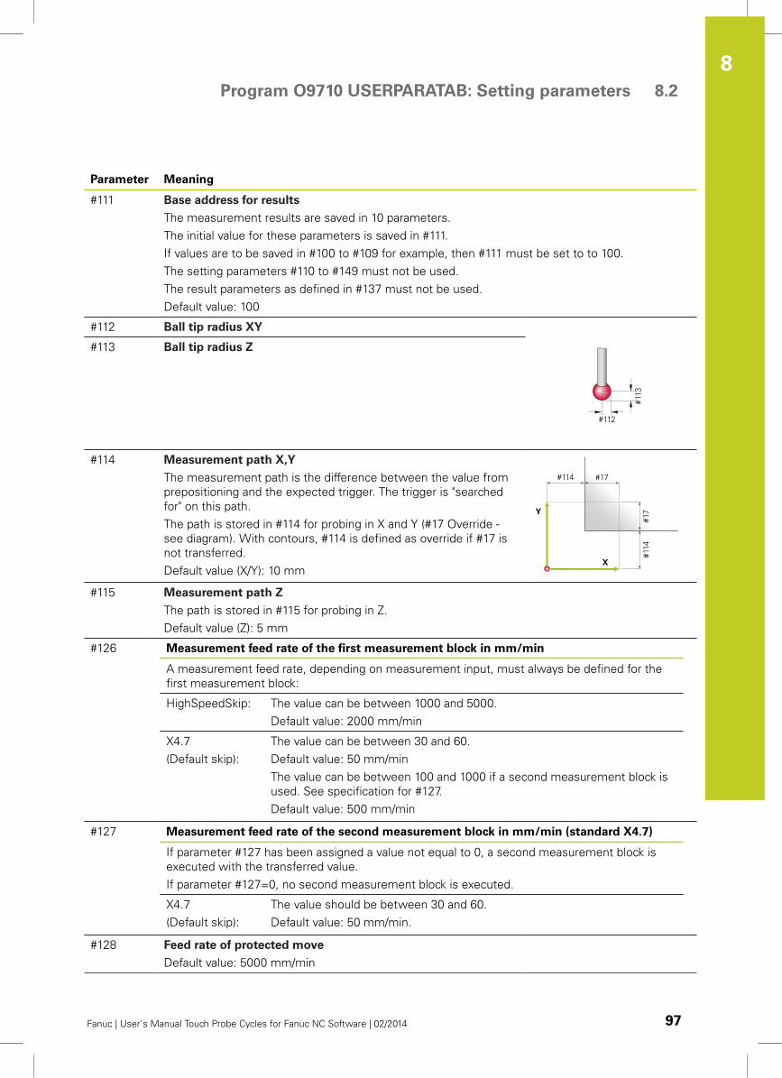
Program O9710 USERPARATAB: Setting parameters 8.2
8
Fanuc | User’s Manual Touch Probe Cycles for Fanuc NC Software | 02/2014 97
Parameter Meaning
#111 Base address for results
The measurement results are saved in 10 parameters.
The initial value for these parameters is saved in #111.
If values are to be saved in #100 to #109 for example, then #111 must be set to to 100.
The setting parameters #110 to #149 must not be used.
The result parameters as defined in #137 must not be used.
Default value: 100
#112 Ball tip radius XY
#113 Ball tip radius Z
#114 Measurement path X,Y
The measurement path is the difference between the value from
prepositioning and the expected trigger. The trigger is "searched
for" on this path.
The path is stored in #114 for probing in X and Y (#17 Override -
see diagram). With contours, #114 is defined as override if #17 is
not transferred.
Default value (X/Y): 10 mm
#115 Measurement path Z
The path is stored in #115 for probing in Z.
Default value (Z): 5 mm
#126 Measurement feed rate of the first measurement block in mm/min
A measurement feed rate, depending on measurement input, must always be defined for the
first measurement block:
HighSpeedSkip: The value can be between 1000 and 5000.
Default value: 2000 mm/min
X4.7
(Default skip):
The value can be between 30 and 60.
Default value: 50 mm/min
The value can be between 100 and 1000 if a second measurement block is
used. See specification for #127.
Default value: 500 mm/min
#127 Measurement feed rate of the second measurement block in mm/min (standard X4.7)
If parameter #127 has been assigned a value not equal to 0, a second measurement block is
executed with the transferred value.
If parameter #127=0, no second measurement block is executed.
X4.7
(Default skip):
The value should be between 30 and 60.
Default value: 50 mm/min.
#128 Feed rate of protected move
Default value: 5000 mm/min
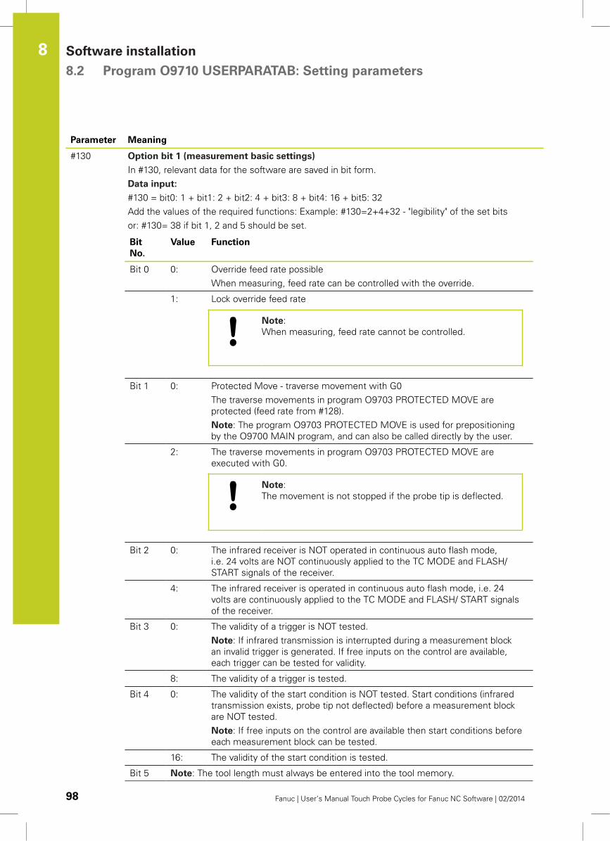
Software installation 8.2 Program O9710 USERPARATAB: Setting parameters
8
98 Fanuc | User’s Manual Touch Probe Cycles for Fanuc NC Software | 02/2014
Parameter Meaning
#130 Option bit 1 (measurement basic settings)
In #130, relevant data for the software are saved in bit form.
Data input:
#130 = bit0: 1 + bit1: 2 + bit2: 4 + bit3: 8 + bit4: 16 + bit5: 32
Add the values of the required functions: Example: #130=2+4+32 - "legibility" of the set bits
or: #130= 38 if bit 1, 2 and 5 should be set.
Bit
No.
Value Function
Bit 0 0: Override feed rate possible
When measuring, feed rate can be controlled with the override.
1: Lock override feed rate
Note:
When measuring, feed rate cannot be controlled.
Bit 1 0: Protected Move - traverse movement with G0
The traverse movements in program O9703 PROTECTED MOVE are
protected (feed rate from #128).
Note: The program O9703 PROTECTED MOVE is used for prepositioning
by the O9700 MAIN program, and can also be called directly by the user.
2: The traverse movements in program O9703 PROTECTED MOVE are
executed with G0.
Note:
The movement is not stopped if the probe tip is deflected.
Bit 2 0: The infrared receiver is NOT operated in continuous auto flash mode,
i.e. 24 volts are NOT continuously applied to the TC MODE and FLASH/
START signals of the receiver.
4: The infrared receiver is operated in continuous auto flash mode, i.e. 24
volts are continuously applied to the TC MODE and FLASH/ START signals
of the receiver.
Bit 3 0: The validity of a trigger is NOT tested.
Note: If infrared transmission is interrupted during a measurement block
an invalid trigger is generated. If free inputs on the control are available,
each trigger can be tested for validity.
8: The validity of a trigger is tested.
Bit 4 0: The validity of the start condition is NOT tested. Start conditions (infrared
transmission exists, probe tip not deflected) before a measurement block
are NOT tested.
Note: If free inputs on the control are available then start conditions before
each measurement block can be tested.
16: The validity of the start condition is tested.
Bit 5 Note: The tool length must always be entered into the tool memory.
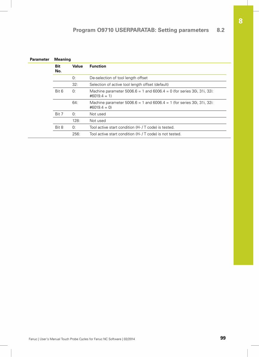
Program O9710 USERPARATAB: Setting parameters 8.2
8
Fanuc | User’s Manual Touch Probe Cycles for Fanuc NC Software | 02/2014 99
Parameter Meaning
Bit
No.
Value Function
0: De-selection of tool length offset
32: Selection of active tool length offset (default)
Bit 6 0: Machine parameter 5006.6 = 1 and 6006.4 = 0 (for series 30i, 31i, 32i:
#6019.4 = 1)
64: Machine parameter 5006.6 = 1 and 6006.4 = 1 (for series 30i, 31i, 32i:
#6019.4 = 0)
Bit 7 0: Not used
128: Not used
Bit 8 0: Tool active start condition (H- / T code) is tested.
256: Tool active start condition (H- / T code) is not tested.
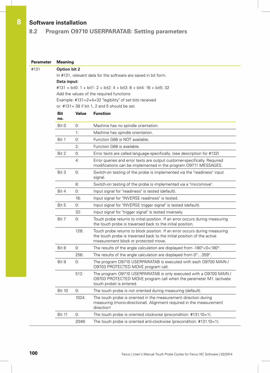
Software installation 8.2 Program O9710 USERPARATAB: Setting parameters
8
100 Fanuc | User’s Manual Touch Probe Cycles for Fanuc NC Software | 02/2014
Parameter Meaning
#131 Option bit 2
In #131, relevant data for the software are saved in bit form.
Data input:
#131 = bit0: 1 + bit1: 2 + bit2: 4 + bit3: 8 + bit4: 16 + bit5: 32
Add the values of the required functions
Example: #131=2+4+32 "legibility" of set bits received
or: #131= 38 if bit 1, 2 and 5 should be set.
Bit
no.
Value Function
Bit 0 0: Machine has no spindle orientation.
1: Machine has spindle orientation.
Bit 1 0: Function G68 is NOT available.
2: Function G68 is available.
Bit 2 0: Error texts are called language-specifically. (see description for #132)
4: Error queries and error texts are output customer-specifically. Required
modifications can be implemented in the program O9711 MESSAGES.
Bit 3 0: Switch-on testing of the probe is implemented via the "readiness" input
signal.
8: Switch-on testing of the probe is implemented via a "micromove".
Bit 4 0: Input signal for "readiness" is tested (default).
16: Input signal for "INVERSE readiness" is tested.
Bit 5 0: Input signal for "INVERSE trigger signal" is tested (default).
32: Input signal for "trigger signal" is tested inversely.
Bit 7 0: Touch probe returns to initial position. If an error occurs during measuring
the touch probe is traversed back to the initial position.
128: Touch probe returns to block position. If an error occurs during measuring
the touch probe is traversed back to the initial position of the active
measurement block or protected move.
Bit 8 0: The results of the angle calculation are displayed from -180°<0<180°.
256: The results of the angle calculation are displayed from 0°…359°.
Bit 9 0: The program O9710 USERPARATAB is executed with each O9700 MAIN /
O9703 PROTECTED MOVE program call.
512: The program O9710 USERPARATAB is only executed with a O9700 MAIN /
O9703 PROTECTED MOVE program call when the parameter M1. (activate
touch probe) is entered.
Bit 10 0: The touch probe is not oriented during measuring (default).
1024: The touch probe is oriented in the measurement direction during
measuring (mono-directional). Alignment required in the measurement
direction!
Bit 11 0: The touch probe is oriented clockwise (precondition: #131.10=1).
2048: The touch probe is oriented anti-clockwise (precondition: #131.10=1).
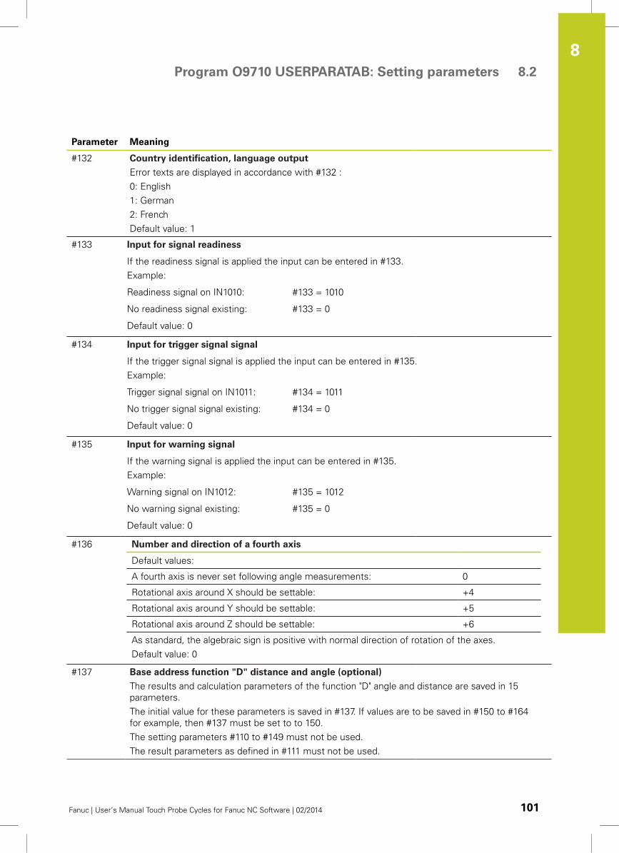
Program O9710 USERPARATAB: Setting parameters 8.2
8
Fanuc | User’s Manual Touch Probe Cycles for Fanuc NC Software | 02/2014 101
Parameter Meaning
#132 Country identification, language output
Error texts are displayed in accordance with #132 :
0: English
1: German
2: French
Default value: 1
#133 Input for signal readiness
If the readiness signal is applied the input can be entered in #133.
Example:
Readiness signal on IN1010: #133 = 1010
No readiness signal existing: #133 = 0
Default value: 0
#134 Input for trigger signal signal
If the trigger signal signal is applied the input can be entered in #135.
Example:
Trigger signal signal on IN1011: #134 = 1011
No trigger signal signal existing: #134 = 0
Default value: 0
#135 Input for warning signal
If the warning signal is applied the input can be entered in #135.
Example:
Warning signal on IN1012: #135 = 1012
No warning signal existing: #135 = 0
Default value: 0
#136 Number and direction of a fourth axis
Default values:
A fourth axis is never set following angle measurements: 0
Rotational axis around X should be settable: +4
Rotational axis around Y should be settable: +5
Rotational axis around Z should be settable: +6
As standard, the algebraic sign is positive with normal direction of rotation of the axes.
Default value: 0
#137 Base address function "D" distance and angle (optional)
The results and calculation parameters of the function "D" angle and distance are saved in 15
parameters.
The initial value for these parameters is saved in #137. If values are to be saved in #150 to #164
for example, then #137 must be set to to 150.
The setting parameters #110 to #149 must not be used.
The result parameters as defined in #111 must not be used.
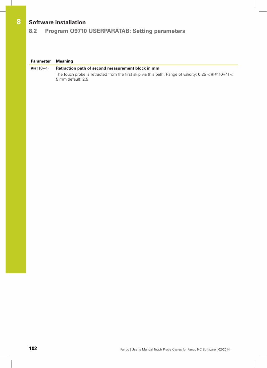
Software installation 8.2 Program O9710 USERPARATAB: Setting parameters
8
102 Fanuc | User’s Manual Touch Probe Cycles for Fanuc NC Software | 02/2014
Parameter Meaning
#(#110+4) Retraction path of second measurement block in mm
The touch probe is retracted from the first skip via this path. Range of validity: 0.25 < #[#110+4] <
5 mm default: 2.5
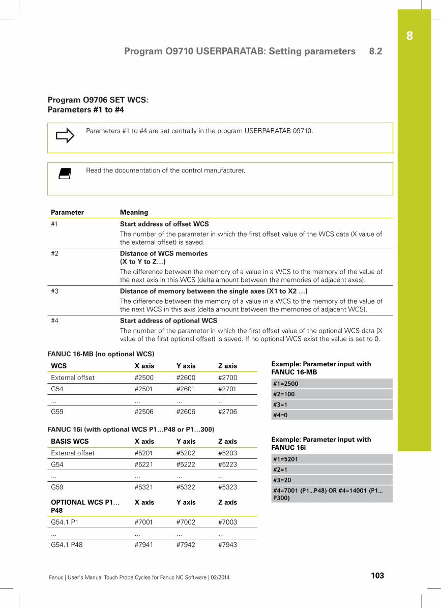
Program O9710 USERPARATAB: Setting parameters 8.2
8
Fanuc | User’s Manual Touch Probe Cycles for Fanuc NC Software | 02/2014 103
Program O9706 SET WCS:
Parameters #1 to #4
Parameters #1 to #4 are set centrally in the program USERPARATAB 09710.
Read the documentation of the control manufacturer.
Parameter Meaning
#1 Start address of offset WCS
The number of the parameter in which the first offset value of the WCS data (X value of
the external offset) is saved.
#2 Distance of WCS memories
(X to Y to Z…)
The difference between the memory of a value in a WCS to the memory of the value of
the next axis in this WCS (delta amount between the memories of adjacent axes).
#3 Distance of memory between the single axes (X1 to X2 …)
The difference between the memory of a value in a WCS to the memory of the value of
the next WCS in this axis (delta amount between the memories of adjacent WCS).
#4 Start address of optional WCS
The number of the parameter in which the first offset value of the optional WCS data (X
value of the first optional offset) is saved. If no optional WCS exist the value is set to 0.
FANUC 16-MB (no optional WCS)
WCS X axis Y axis Z axis
External offset #2500 #2600 #2700
G54 #2501 #2601 #2701
... ... ... ...
G59 #2506 #2606 #2706
Example: Parameter input with
FANUC 16-MB
#1=2500
#2=100
#3=1
#4=0
FANUC 16i (with optional WCS P1…P48 or P1…300)
BASIS WCS X axis Y axis Z axis
External offset #5201 #5202 #5203
G54 #5221 #5222 #5223
... ... ... ...
G59 #5321 #5322 #5323
OPTIONAL WCS P1…
P48
X axis Y axis Z axis
G54.1 P1 #7001 #7002 #7003
... ... ... ...
G54.1 P48 #7941 #7942 #7943
Example: Parameter input with
FANUC 16i
#1=5201
#2=1
#3=20
#4=7001 (P1…P48) OR #4=14001 (P1…P300)
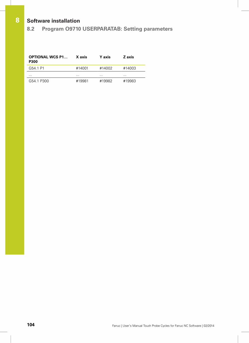
Software installation 8.2 Program O9710 USERPARATAB: Setting parameters
8
104 Fanuc | User’s Manual Touch Probe Cycles for Fanuc NC Software | 02/2014
OPTIONAL WCS P1…
P300
X axis Y axis Z axis
G54.1 P1 #14001 #14002 #14003
... ... ... ...
G54.1 P300 #19981 #19982 #19983
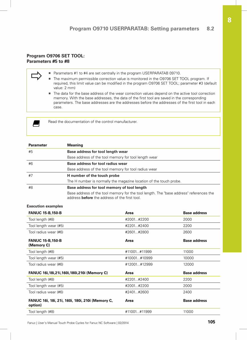
Program O9710 USERPARATAB: Setting parameters 8.2
8
Fanuc | User’s Manual Touch Probe Cycles for Fanuc NC Software | 02/2014 105
Program O9706 SET TOOL:
Parameters #5 to #8
Parameters #1 to #4 are set centrally in the program USERPARATAB 09710.
The maximum permissible correction value is monitored in the O9706 SET TOOL program. If
required, this limit value can be modified in the program O9706 SET TOOL; parameter #3 (default
value: 2 mm)
The data for the base address of the wear correction values depend on the active tool correction
memory. With the base addresses, the data of the first tool are saved in the corresponding
parameters. The base addresses are the addresses before the addresses of the first tool in each
case.
Read the documentation of the control manufacturer.
Parameter Meaning
#5 Base address for tool length wear
Base address of the tool memory for tool length wear
#6 Base address for tool radius wear
Base address of the tool memory for tool radius wear
#7 H number of the touch probe
The H number is normally the magazine location of the touch probe.
#8 Base address for tool memory of tool length
Base address of the tool memory for the tool length. The "base address" references the
address before the address of the first tool.
Execution examples
FANUC 15-B,150-B Area Base address
Tool length (#8) #2001...#2200 2000
Tool length wear (#5) #2201...#2400 2200
Tool radius wear (#6) #2601...#2800 2600
FANUC 15-B,150-B
(Memory C)
Area Base address
Tool length (#8) #11001...#11999 11000
Tool length wear (#5) #10001...#10999 10000
Tool radius wear (#6) #12001...#12999 12000
FANUC 16i,18i,21i,160i,180i,210i (Memory C) Area Base address
Tool length (#8) #2201...#2400 2200
Tool length wear (#5) #2001...#2200 2000
Tool radius wear (#6) #2401...#2600 2400
FANUC 16i, 18i, 21i, 160i, 180i, 210i (Memory C,
option)
Area Base address
Tool length (#8) #11001...#11999 11000
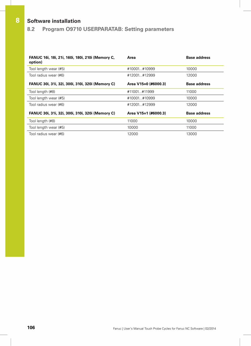
Software installation 8.2 Program O9710 USERPARATAB: Setting parameters
8
106 Fanuc | User’s Manual Touch Probe Cycles for Fanuc NC Software | 02/2014
FANUC 16i, 18i, 21i, 160i, 180i, 210i (Memory C,
option)
Area Base address
Tool length wear (#5) #10001...#10999 10000
Tool radius wear (#6) #12001...#12999 12000
FANUC 30i, 31i, 32i, 300i, 310i, 320i (Memory C) Area V15=0 (#6000.3) Base address
Tool length (#8) #11001...#11999 11000
Tool length wear (#5) #10001...#10999 10000
Tool radius wear (#6) #12001...#12999 12000
FANUC 30i, 31i, 32i, 300i, 310i, 320i (Memory C) Area V15=1 (#6000.3) Base address
Tool length (#8) 11000 10000
Tool length wear (#5) 10000 11000
Tool radius wear (#6) 12000 13000
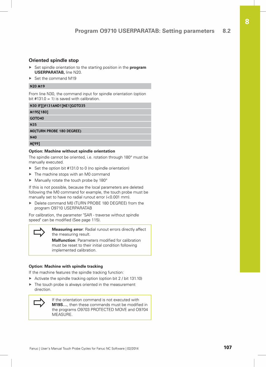
Program O9710 USERPARATAB: Setting parameters 8.2
8
Fanuc | User’s Manual Touch Probe Cycles for Fanuc NC Software | 02/2014 107
Oriented spindle stop
Set spindle orientation to the starting position in the program
USERPARATAB, line N20.
Set the command M19
N20 M19
From line N30, the command input for spindle orientation (option
bit #131.0 = 1) is saved with calibration.
N30 IF[[#131AND1]NE1]GOTO35
M19S[180]
GOTO40
N35
M0(TURN PROBE 180 DEGREE)
N40
M[99]
Option: Machine without spindle orientation
The spindle cannot be oriented, i.e. rotation through 180° must be
manually executed.
Set the option bit #131.0 to 0 (no spindle orientation)
The machine stops with an M0 command
Manually rotate the touch probe by 180°
If this is not possible, because the local parameters are deleted
following the M0 command for example, the touch probe must be
manually set to have no radial runout error (<0.001 mm).
Delete command M0 (TURN PROBE 180 DEGREE) from the
program O9710 USERPARATAB
For calibration, the parameter "SAR - traverse without spindle
speed" can be modified (See page 115).
Measuring error: Radial runout errors directly affect
the measuring result.
Malfunction: Parameters modified for calibration
must be reset to their initial condition following
implemented calibration.
Option: Machine with spindle tracking
If the machine features the spindle tracking function:
Activate the spindle tracking option (option bit 2 / bit 131.10)
The touch probe is always oriented in the measurement
direction.
If the orientation command is not executed with
M19S…, then these commands must be modified in
the programs O9703 PROTECTED MOVE and O9704
MEASURE.
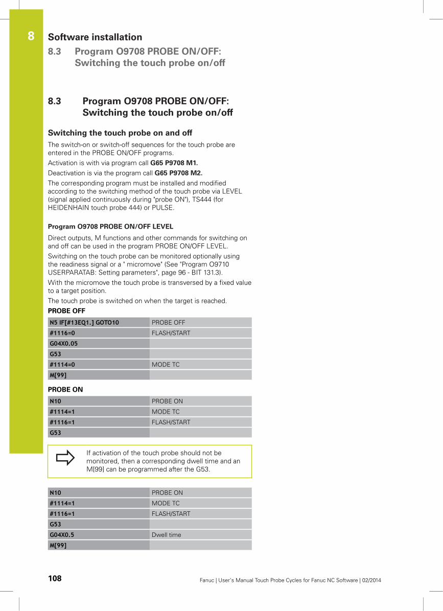
Software installation 8.3 Program O9708 PROBE ON/OFF:
Switching the touch probe on/off
8
108 Fanuc | User’s Manual Touch Probe Cycles for Fanuc NC Software | 02/2014
8.3 Program O9708 PROBE ON/OFF:
Switching the touch probe on/off
Switching the touch probe on and off
The switch-on or switch-off sequences for the touch probe are
entered in the PROBE ON/OFF programs.
Activation is with via program call G65 P9708 M1.
Deactivation is via the program call G65 P9708 M2.
The corresponding program must be installed and modified
according to the switching method of the touch probe via LEVEL
(signal applied continuously during "probe ON"), TS444 (for
HEIDENHAIN touch probe 444) or PULSE.
Program O9708 PROBE ON/OFF LEVEL
Direct outputs, M functions and other commands for switching on
and off can be used in the program PROBE ON/OFF LEVEL.
Switching on the touch probe can be monitored optionally using
the readiness signal or a " micromove" (See "Program O9710
USERPARATAB: Setting parameters", page 96 - BIT 131.3).
With the micromove the touch probe is transversed by a fixed value
to a target position.
The touch probe is switched on when the target is reached.
PROBE OFF
N5 IF[#13EQ1.] GOTO10 PROBE OFF
#1116=0 FLASH/START
G04X0.05
G53
#1114=0 MODE TC
M[99]
PROBE ON
N10 PROBE ON
#1114=1 MODE TC
#1116=1 FLASH/START
G53
If activation of the touch probe should not be
monitored, then a corresponding dwell time and an
M[99] can be programmed after the G53.
N10 PROBE ON
#1114=1 MODE TC
#1116=1 FLASH/START
G53
G04X0.5 Dwell time
M[99]
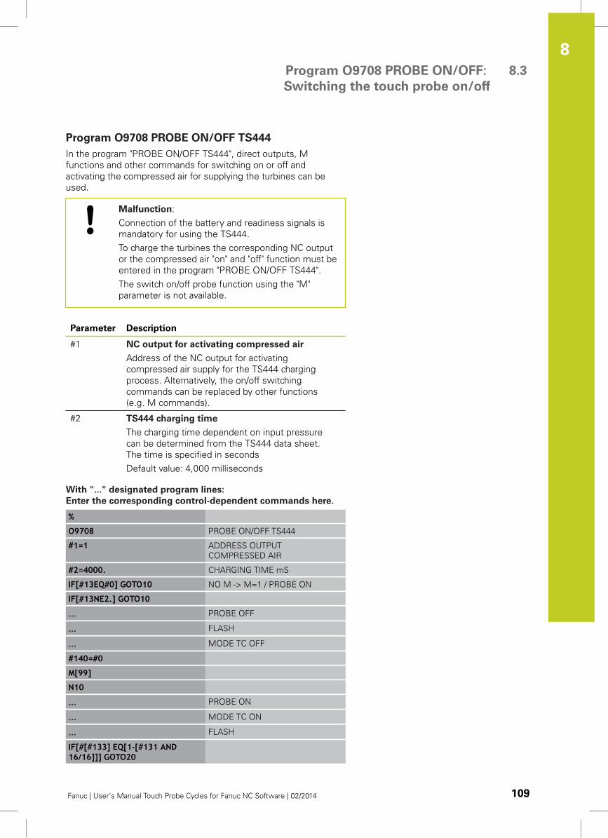
Program O9708 PROBE ON/OFF:
Switching the touch probe on/off
8.3
8
Fanuc | User’s Manual Touch Probe Cycles for Fanuc NC Software | 02/2014 109
Program O9708 PROBE ON/OFF TS444
In the program "PROBE ON/OFF TS444", direct outputs, M
functions and other commands for switching on or off and
activating the compressed air for supplying the turbines can be
used.
Malfunction:
Connection of the battery and readiness signals is
mandatory for using the TS444.
To charge the turbines the corresponding NC output
or the compressed air "on" and "off" function must be
entered in the program "PROBE ON/OFF TS444".
The switch on/off probe function using the "M"
parameter is not available.
Parameter Description
#1 NC output for activating compressed air
Address of the NC output for activating
compressed air supply for the TS444 charging
process. Alternatively, the on/off switching
commands can be replaced by other functions
(e.g. M commands).
#2 TS444 charging time
The charging time dependent on input pressure
can be determined from the TS444 data sheet.
The time is specified in seconds
Default value: 4,000 milliseconds
With "..." designated program lines:
Enter the corresponding control-dependent commands here.
%
O9708 PROBE ON/OFF TS444
#1=1 ADDRESS OUTPUT
COMPRESSED AIR
#2=4000. CHARGING TIME mS
IF[#13EQ#0] GOTO10 NO M -> M=1 / PROBE ON
IF[#13NE2.] GOTO10
... PROBE OFF
... FLASH
... MODE TC OFF
#140=#0
M[99]
N10
... PROBE ON
... MODE TC ON
... FLASH
IF[#[#133] EQ[1-[#131 AND16/16]]] GOTO20
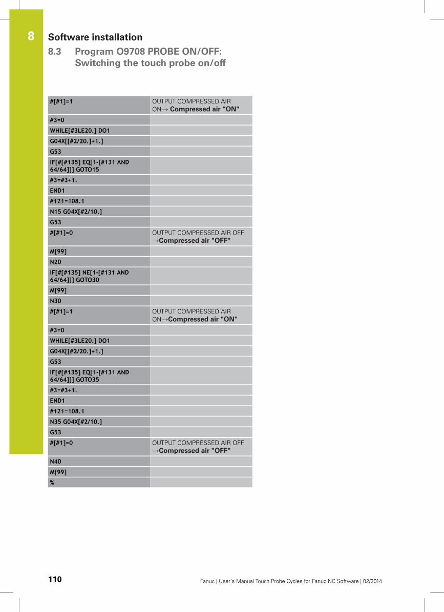
Software installation 8.3 Program O9708 PROBE ON/OFF:
Switching the touch probe on/off
8
110 Fanuc | User’s Manual Touch Probe Cycles for Fanuc NC Software | 02/2014
#[#1]=1 OUTPUT COMPRESSED AIR
ON→ Compressed air "ON"
#3=0
WHILE[#3LE20.] DO1
G04X[[#2/20.]+1.]
G53
IF[#[#135] EQ[1-[#131 AND64/64]]] GOTO15
#3=#3+1.
END1
#121=108.1
N15 G04X[#2/10.]
G53
#[#1]=0 OUTPUT COMPRESSED AIR OFF
→Compressed air "OFF"
M[99]
N20
IF[#[#135] NE[1-[#131 AND64/64]]] GOTO30
M[99]
N30
#[#1]=1 OUTPUT COMPRESSED AIR
ON→Compressed air "ON"
#3=0
WHILE[#3LE20.] DO1
G04X[[#2/20.]+1.]
G53
IF[#[#135] EQ[1-[#131 AND64/64]]] GOTO35
#3=#3+1.
END1
#121=108.1
N35 G04X[#2/10.]
G53
#[#1]=0 OUTPUT COMPRESSED AIR OFF
→Compressed air "OFF"
N40
M[99]
%
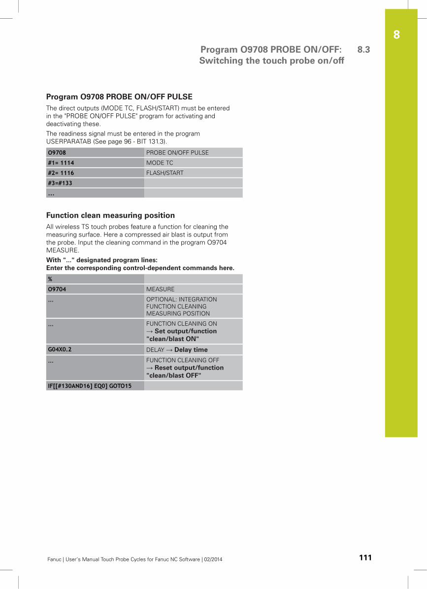
Program O9708 PROBE ON/OFF:
Switching the touch probe on/off
8.3
8
Fanuc | User’s Manual Touch Probe Cycles for Fanuc NC Software | 02/2014 111
Program O9708 PROBE ON/OFF PULSE
The direct outputs (MODE TC, FLASH/START) must be entered
in the "PROBE ON/OFF PULSE" program for activating and
deactivating these.
The readiness signal must be entered in the program
USERPARATAB (See page 96 - BIT 131.3).
O9708 PROBE ON/OFF PULSE
#1= 1114 MODE TC
#2= 1116 FLASH/START
#3=#133
...
Function clean measuring position
All wireless TS touch probes feature a function for cleaning the
measuring surface. Here a compressed air blast is output from
the probe. Input the cleaning command in the program O9704
MEASURE.
With "..." designated program lines:
Enter the corresponding control-dependent commands here.
%
O9704 MEASURE
... OPTIONAL: INTEGRATION
FUNCTION CLEANING
MEASURING POSITION
... FUNCTION CLEANING ON
→ Set output/function
"clean/blast ON"
G04X0.2 DELAY → Delay time
... FUNCTION CLEANING OFF
→ Reset output/function
"clean/blast OFF"
IF[[#130AND16] EQ0] GOTO15
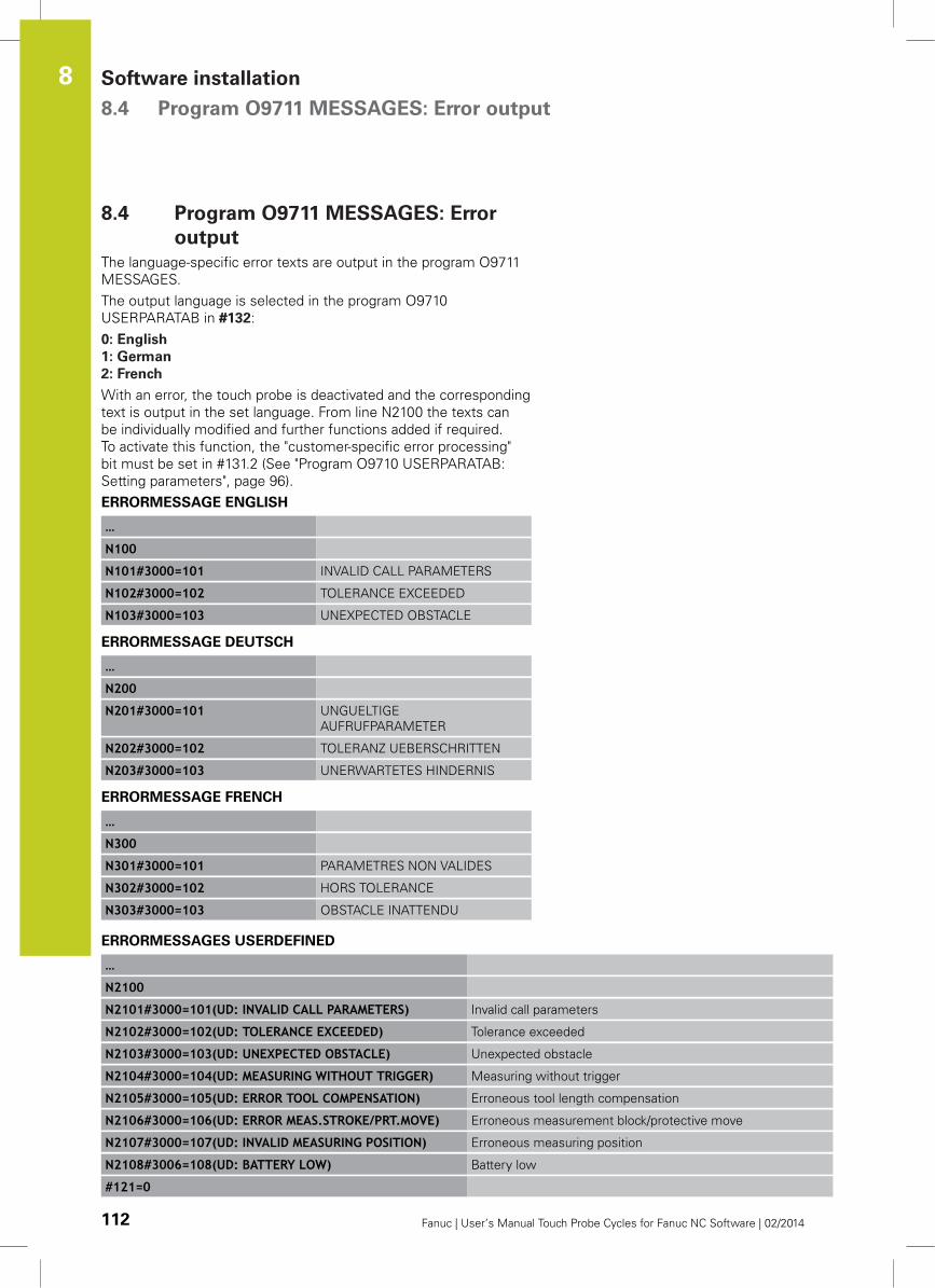
Software installation 8.4 Program O9711 MESSAGES: Error output
8
112 Fanuc | User’s Manual Touch Probe Cycles for Fanuc NC Software | 02/2014
8.4 Program O9711 MESSAGES: Error
output
The language-specific error texts are output in the program O9711
MESSAGES.
The output language is selected in the program O9710
USERPARATAB in #132:
0: English
1: German
2: French
With an error, the touch probe is deactivated and the corresponding
text is output in the set language. From line N2100 the texts can
be individually modified and further functions added if required.
To activate this function, the "customer-specific error processing"
bit must be set in #131.2 (See "Program O9710 USERPARATAB:
Setting parameters", page 96).
ERRORMESSAGE ENGLISH
…
N100
N101#3000=101 INVALID CALL PARAMETERS
N102#3000=102 TOLERANCE EXCEEDED
N103#3000=103 UNEXPECTED OBSTACLE
ERRORMESSAGE DEUTSCH
…
N200
N201#3000=101 UNGUELTIGE
AUFRUFPARAMETER
N202#3000=102 TOLERANZ UEBERSCHRITTEN
N203#3000=103 UNERWARTETES HINDERNIS
ERRORMESSAGE FRENCH
…
N300
N301#3000=101 PARAMETRES NON VALIDES
N302#3000=102 HORS TOLERANCE
N303#3000=103 OBSTACLE INATTENDU
ERRORMESSAGES USERDEFINED
…
N2100
N2101#3000=101(UD: INVALID CALL PARAMETERS) Invalid call parameters
N2102#3000=102(UD: TOLERANCE EXCEEDED) Tolerance exceeded
N2103#3000=103(UD: UNEXPECTED OBSTACLE) Unexpected obstacle
N2104#3000=104(UD: MEASURING WITHOUT TRIGGER) Measuring without trigger
N2105#3000=105(UD: ERROR TOOL COMPENSATION) Erroneous tool length compensation
N2106#3000=106(UD: ERROR MEAS.STROKE/PRT.MOVE) Erroneous measurement block/protective move
N2107#3000=107(UD: INVALID MEASURING POSITION) Erroneous measuring position
N2108#3006=108(UD: BATTERY LOW) Battery low
#121=0
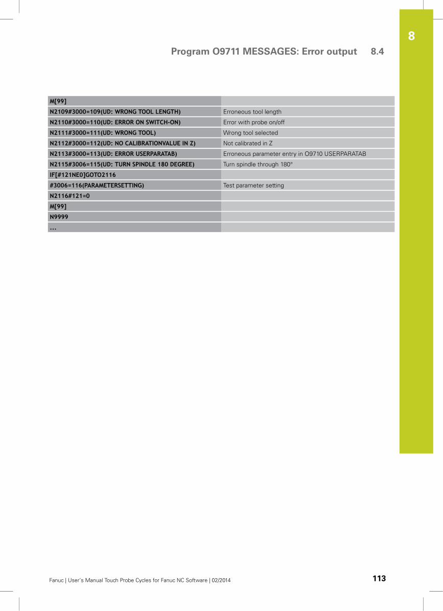
Program O9711 MESSAGES: Error output 8.4
8
Fanuc | User’s Manual Touch Probe Cycles for Fanuc NC Software | 02/2014 113
M[99]
N2109#3000=109(UD: WRONG TOOL LENGTH) Erroneous tool length
N2110#3000=110(UD: ERROR ON SWITCH-ON) Error with probe on/off
N2111#3000=111(UD: WRONG TOOL) Wrong tool selected
N2112#3000=112(UD: NO CALIBRATIONVALUE IN Z) Not calibrated in Z
N2113#3000=113(UD: ERROR USERPARATAB) Erroneous parameter entry in O9710 USERPARATAB
N2115#3006=115(UD: TURN SPINDLE 180 DEGREE) Turn spindle through 180°
IF[#121NE0]GOTO2116
#3006=116(PARAMETERSETTING) Test parameter setting
N2116#121=0
M[99]
N9999
...
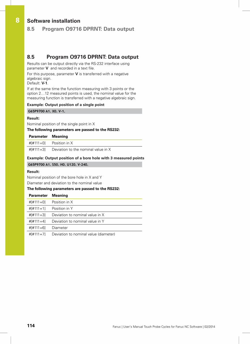
Software installation 8.5 Program O9716 DPRNT: Data output
8
114 Fanuc | User’s Manual Touch Probe Cycles for Fanuc NC Software | 02/2014
8.5 Program O9716 DPRNT: Data output
Results can be output directly via the RS-232 interface using
parameter V and recorded in a text file.
For this purpose, parameter V is transferred with a negative
algebraic sign.
Default: V-1.
If at the same time the function measuring with 3 points or the
option 2…12 measured points is used, the nominal value for the
measuring function is transferred with a negative algebraic sign.
Example: Output position of a single point
G65P9700 A1. X0. V-1.
Result:
Nominal position of the single point in X
The following parameters are passed to the RS232:
Parameter Meaning
#[#111+0] Position in X
#[#111+3] Deviation to the nominal value in X
Example: Output position of a bore hole with 3 measured points
G65P9700 A1. S50. H0. U120. V-240.
Result:
Nominal position of the bore hole in X and Y
Diameter and deviation to the nominal value
The following parameters are passed to the RS232:
Parameter Meaning
#[#111+0] Position in X
#[#111+1] Position in Y
#[#111+3] Deviation to nominal value in X
#[#111+4] Deviation to nominal value in Y
#[#111+6] Diameter
#[#111+7] Deviation to nominal value (diameter)
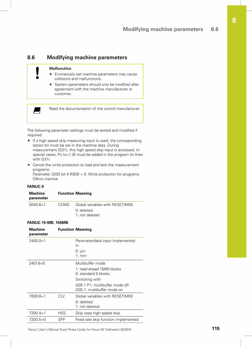
Modifying machine parameters 8.6
8
Fanuc | User’s Manual Touch Probe Cycles for Fanuc NC Software | 02/2014 115
8.6 Modifying machine parameters
Malfunction
Erroneously set machine parameters may cause
collisions and malfunctions.
System parameters should only be modified after
agreement with the machine manufacturer or
customer.
Read the documentation of the control manufacturer.
The following parameter settings must be tested and modified if
required.
If a high speed skip measuring input is used, the corresponding
option bit must be set in the machine data. During
measurement (G31), this high speed skip input is accessed. In
special cases, Px (x=1..8) must be added in the program (in lines
with G31).
Cancel the write protection to load and test the measurement
programs:
Parameter 3202 bit 4 (NE9) = 0: Write protection for programs
O9xxx inactive
FANUC 0
Machine
parameter
Function Meaning
0040.6=1 COMC Global variables with RESET/M00
0: deleted
1: not deleted
FANUC 15-MB, 150MB
Machine
parameter
Function Meaning
2400.0=1 Parameter/data input implemented
in
0: µm
1: mm
2401.6=0 Multibuffer mode
1: read ahead 15/60 blocks
0: standard 5 blocks
Switching with
G05.1 P1: multibuffer mode off
G05.1: multibuffer mode on
7000.6=1 CLV Global variables with RESET/M00
0: deleted
1: not deleted
7200.4=1 HSS Skip uses high speed skip
7200.5=0 SFP Feed rate skip function implemented
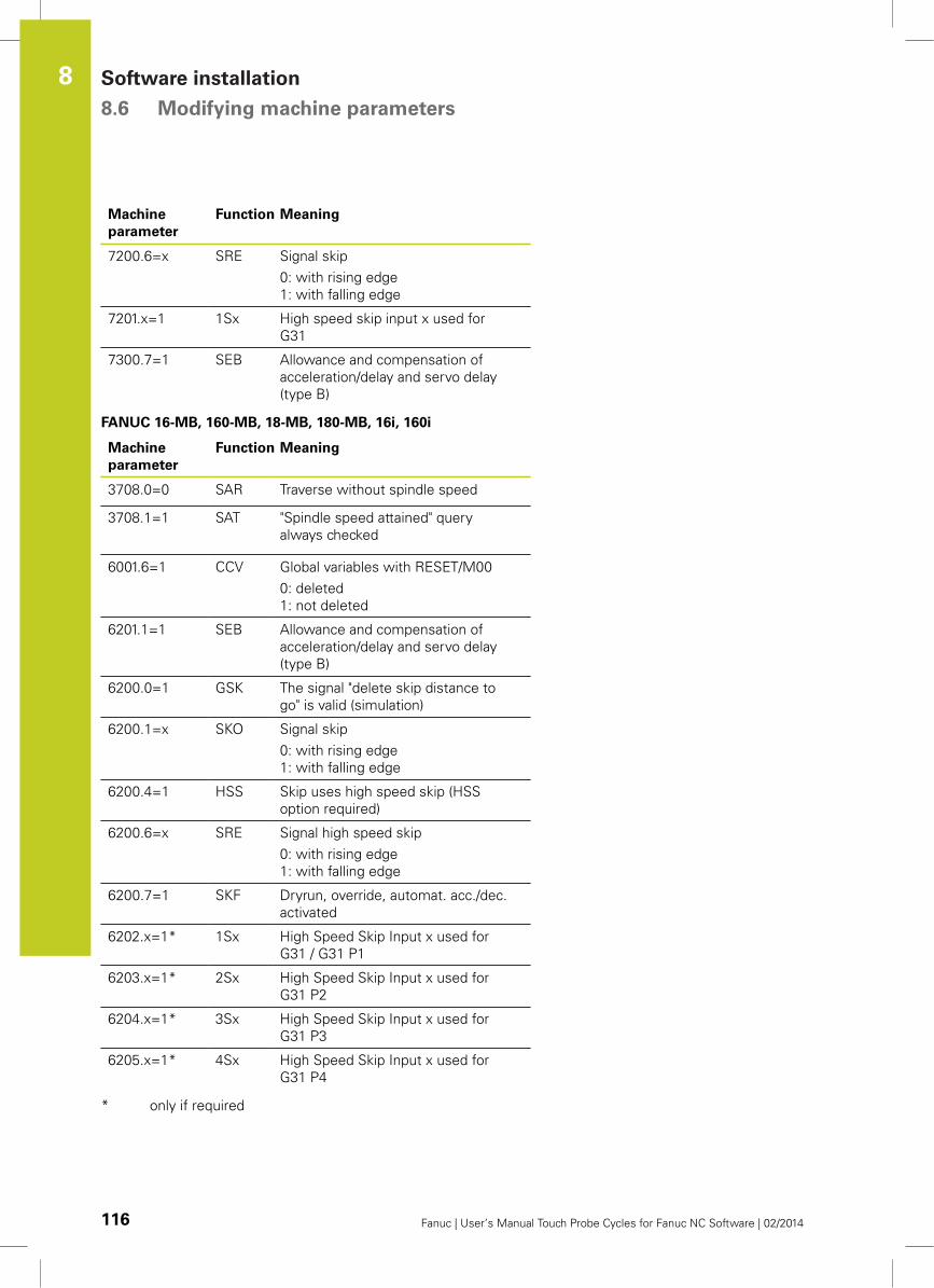
Software installation 8.6 Modifying machine parameters
8
116 Fanuc | User’s Manual Touch Probe Cycles for Fanuc NC Software | 02/2014
Machine
parameter
Function Meaning
7200.6=x SRE Signal skip
0: with rising edge
1: with falling edge
7201.x=1 1Sx High speed skip input x used for
G31
7300.7=1 SEB Allowance and compensation of
acceleration/delay and servo delay
(type B)
FANUC 16-MB, 160-MB, 18-MB, 180-MB, 16i, 160i
Machine
parameter
Function Meaning
3708.0=0 SAR Traverse without spindle speed
3708.1=1 SAT "Spindle speed attained" query
always checked
6001.6=1 CCV Global variables with RESET/M00
0: deleted
1: not deleted
6201.1=1 SEB Allowance and compensation of
acceleration/delay and servo delay
(type B)
6200.0=1 GSK The signal "delete skip distance to
go" is valid (simulation)
6200.1=x SKO Signal skip
0: with rising edge
1: with falling edge
6200.4=1 HSS Skip uses high speed skip (HSS
option required)
6200.6=x SRE Signal high speed skip
0: with rising edge
1: with falling edge
6200.7=1 SKF Dryrun, override, automat. acc./dec.
activated
6202.x=1* 1Sx High Speed Skip Input x used for
G31 / G31 P1
6203.x=1* 2Sx High Speed Skip Input x used for
G31 P2
6204.x=1* 3Sx High Speed Skip Input x used for
G31 P3
6205.x=1* 4Sx High Speed Skip Input x used for
G31 P4
* only if required
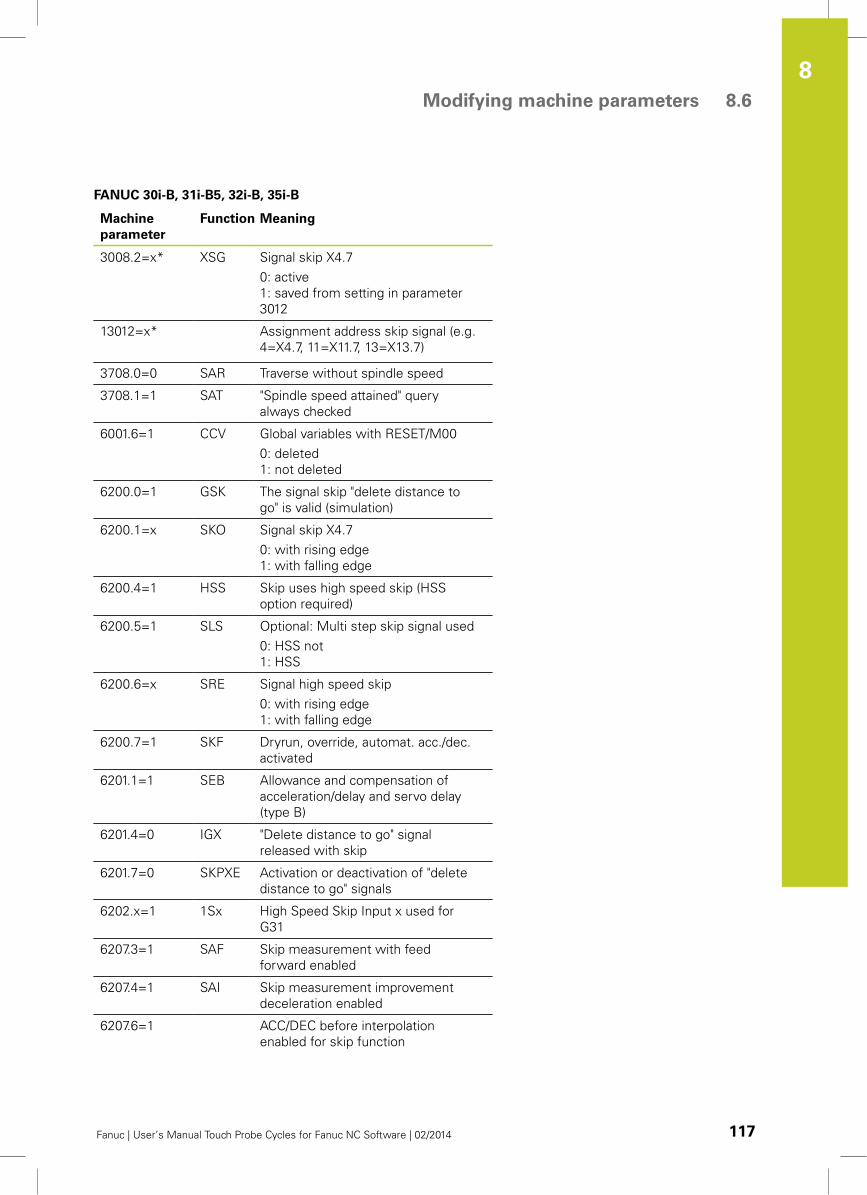
Modifying machine parameters 8.6
8
Fanuc | User’s Manual Touch Probe Cycles for Fanuc NC Software | 02/2014 117
FANUC 30i-B, 31i-B5, 32i-B, 35i-B
Machine
parameter
Function Meaning
3008.2=x* XSG Signal skip X4.7
0: active
1: saved from setting in parameter
3012
13012=x* Assignment address skip signal (e.g.
4=X4.7, 11=X11.7, 13=X13.7)
3708.0=0 SAR Traverse without spindle speed
3708.1=1 SAT "Spindle speed attained" query
always checked
6001.6=1 CCV Global variables with RESET/M00
0: deleted
1: not deleted
6200.0=1 GSK The signal skip "delete distance to
go" is valid (simulation)
6200.1=x SKO Signal skip X4.7
0: with rising edge
1: with falling edge
6200.4=1 HSS Skip uses high speed skip (HSS
option required)
6200.5=1 SLS Optional: Multi step skip signal used
0: HSS not
1: HSS
6200.6=x SRE Signal high speed skip
0: with rising edge
1: with falling edge
6200.7=1 SKF Dryrun, override, automat. acc./dec.
activated
6201.1=1 SEB Allowance and compensation of
acceleration/delay and servo delay
(type B)
6201.4=0 IGX "Delete distance to go" signal
released with skip
6201.7=0 SKPXE Activation or deactivation of "delete
distance to go" signals
6202.x=1 1Sx High Speed Skip Input x used for
G31
6207.3=1 SAF Skip measurement with feed
forward enabled
6207.4=1 SAI Skip measurement improvement
deceleration enabled
6207.6=1 ACC/DEC before interpolation
enabled for skip function
Software installation 8.6 Modifying machine parameters
8
118 Fanuc | User’s Manual Touch Probe Cycles for Fanuc NC Software | 02/2014
* only with use of skip X4.7.
These parameters must only be modified by the
machine manufacturer.
Switching Units of Measurement (metric / inch) 8.7
8
Fanuc | User’s Manual Touch Probe Cycles for Fanuc NC Software | 02/2014 119
8.7 Switching Units of Measurement
(metric / inch)
Read the documentation of the control manufacturer.
Measuring error: Recalibrate the system after
switching the unit of measurement from mm to
inches or vice versa.
Malfunction: The machine must be switched off and
then on again to activate the set parameters.
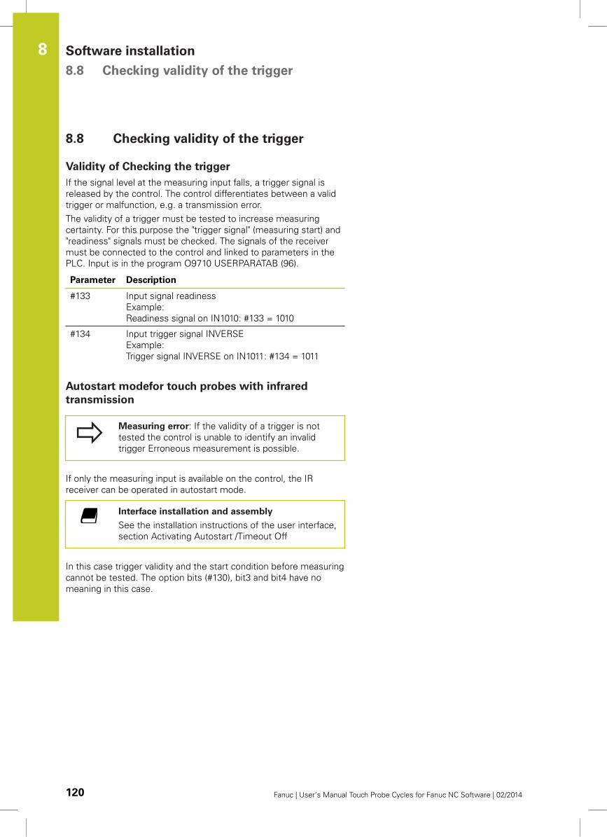
Software installation 8.8 Checking validity of the trigger
8
120 Fanuc | User’s Manual Touch Probe Cycles for Fanuc NC Software | 02/2014
8.8 Checking validity of the trigger
Validity of Checking the trigger
If the signal level at the measuring input falls, a trigger signal is
released by the control. The control differentiates between a valid
trigger or malfunction, e.g. a transmission error.
The validity of a trigger must be tested to increase measuring
certainty. For this purpose the "trigger signal" (measuring start) and
"readiness" signals must be checked. The signals of the receiver
must be connected to the control and linked to parameters in the
PLC. Input is in the program O9710 USERPARATAB (96).
Parameter Description
#133 Input signal readiness
Example:
Readiness signal on IN1010: #133 = 1010
#134 Input trigger signal INVERSE
Example:
Trigger signal INVERSE on IN1011: #134 = 1011
Autostart modefor touch probes with infrared
transmission
Measuring error: If the validity of a trigger is not
tested the control is unable to identify an invalid
trigger Erroneous measurement is possible.
If only the measuring input is available on the control, the IR
receiver can be operated in autostart mode.
Interface installation and assembly
See the installation instructions of the user interface,
section Activating Autostart /Timeout Off
In this case trigger validity and the start condition before measuring
cannot be tested. The option bits (#130), bit3 and bit4 have no
meaning in this case.
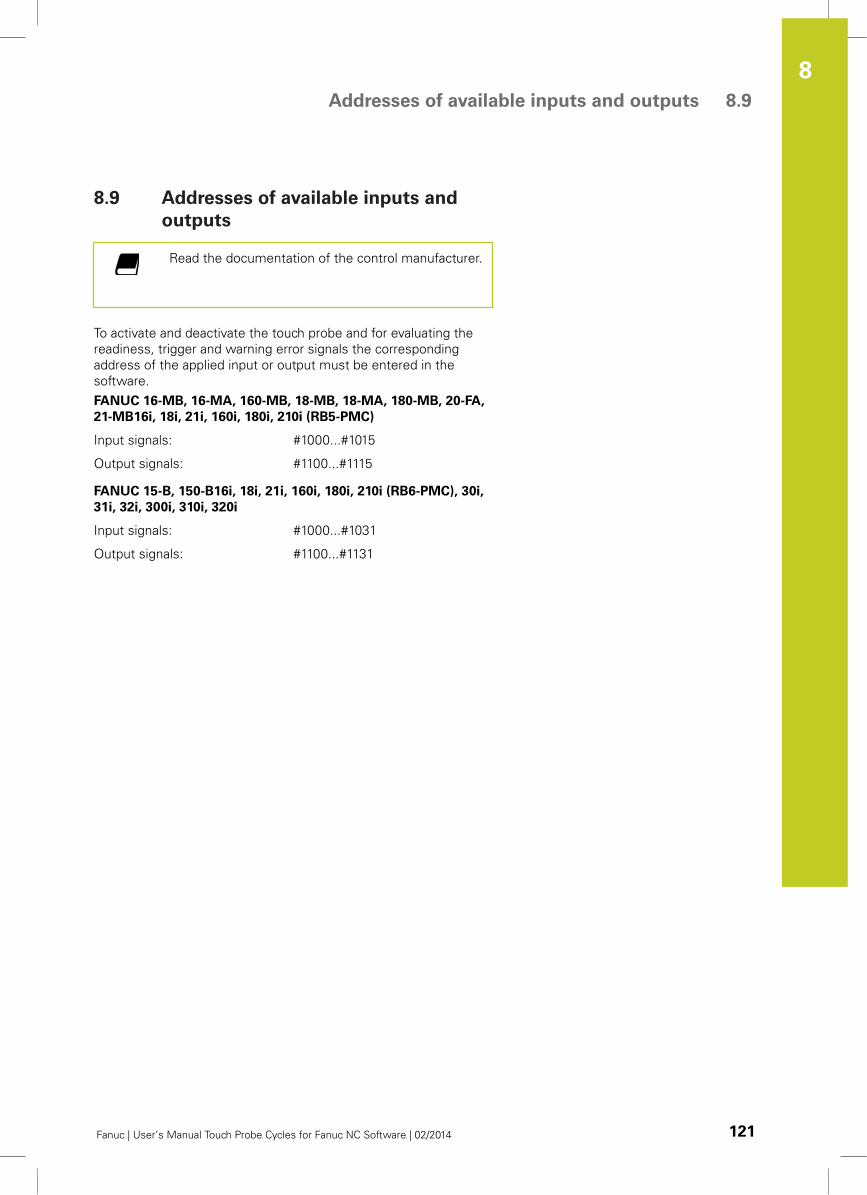
Addresses of available inputs and outputs 8.9
8
Fanuc | User’s Manual Touch Probe Cycles for Fanuc NC Software | 02/2014 121
8.9 Addresses of available inputs and
outputs
Read the documentation of the control manufacturer.
To activate and deactivate the touch probe and for evaluating the
readiness, trigger and warning error signals the corresponding
address of the applied input or output must be entered in the
software.
FANUC 16-MB, 16-MA, 160-MB, 18-MB, 18-MA, 180-MB, 20-FA,
21-MB16i, 18i, 21i, 160i, 180i, 210i (RB5-PMC)
Input signals: #1000...#1015
Output signals: #1100...#1115
FANUC 15-B, 150-B16i, 18i, 21i, 160i, 180i, 210i (RB6-PMC), 30i,
31i, 32i, 300i, 310i, 320i
Input signals: #1000...#1031
Output signals: #1100...#1131

9Fanuc
GUI Installation
Fanuc
GUI Installation 9.1 Fanuc GUI installation
9
124 Fanuc | User’s Manual Touch Probe Cycles for Fanuc NC Software | 02/2014
9.1 Fanuc GUI installation
Fundamentals
The graphical user interface (GUI: Graphical User Interface) is a
software component that supports the user with input masks,
images and texts when creating the cycle programs.
The Fanuc GUI supports the following encoders:
all HEIDENHAIN TS systems
all HEIDENHAIN TT systems
The existing software package contains the graphical user interface
for all specified encoders.
The individual interfaces are activated during installation with the
system parameter 8801.
Read and observe the documentation of the control
manufacturer before installing the software package.
The graphical user interface (GUI) has been designed
for the FANUC control with "Manual Guide i".
Requirements for installation
Malfunction possible via modifications to system
parameters and files
Installation should only be carried out by
authorized personnel
The files "CEX2DATU" and "CEX3DATU" from other
manufacturers must not be installed
The system parameter 8801 must not be
assigned
Requirements
GE FANUC control with "Manual Guide i"
Memory requirements: 700 KB
The HEIDENHAIN encoder used must be installed
and be completely operational
Data backup
Malfunction possible due to data loss
Backup existing data before installing the new
data.
Activate the CF card with the key "OFFSET/SETTING"
Press the "SETTINGS" soft key
Select parameter "4" in the "I/O channel" screen display line
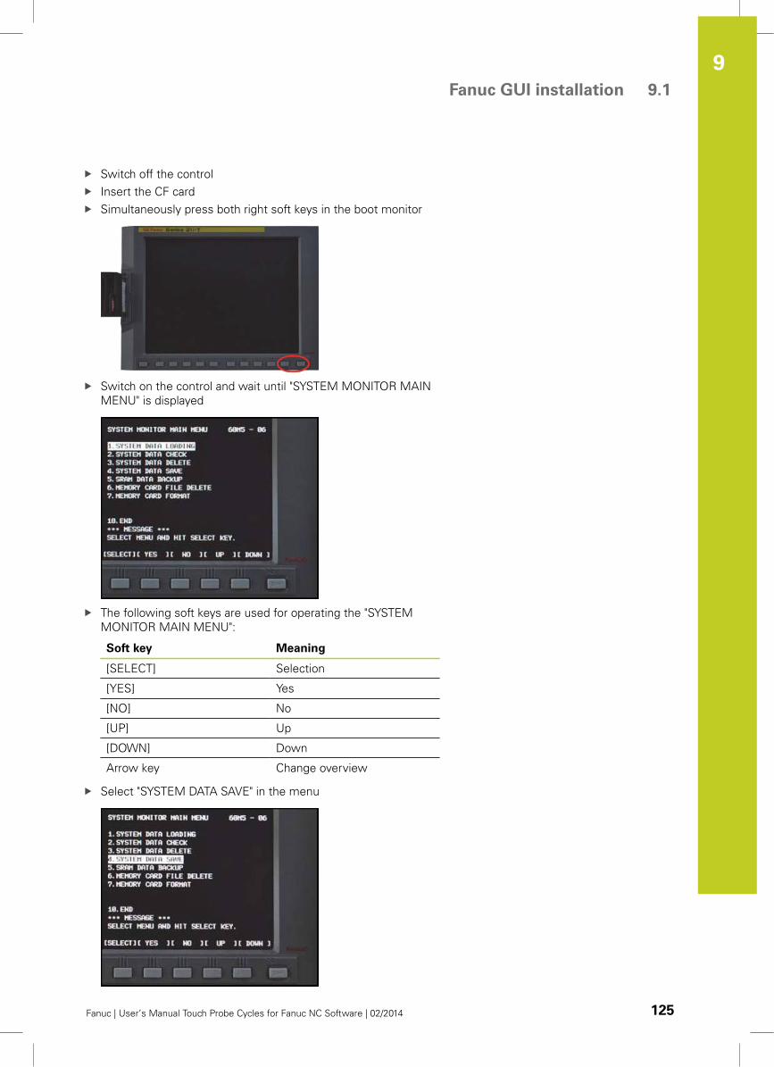
Fanuc GUI installation 9.1
9
Fanuc | User’s Manual Touch Probe Cycles for Fanuc NC Software | 02/2014 125
Switch off the control
Insert the CF card
Simultaneously press both right soft keys in the boot monitor
Switch on the control and wait until "SYSTEM MONITOR MAIN
MENU" is displayed
The following soft keys are used for operating the "SYSTEM
MONITOR MAIN MENU":
Soft key Meaning
[SELECT] Selection
[YES] Yes
[NO] No
[UP] Up
[DOWN] Down
Arrow key Change overview
Select "SYSTEM DATA SAVE" in the menu
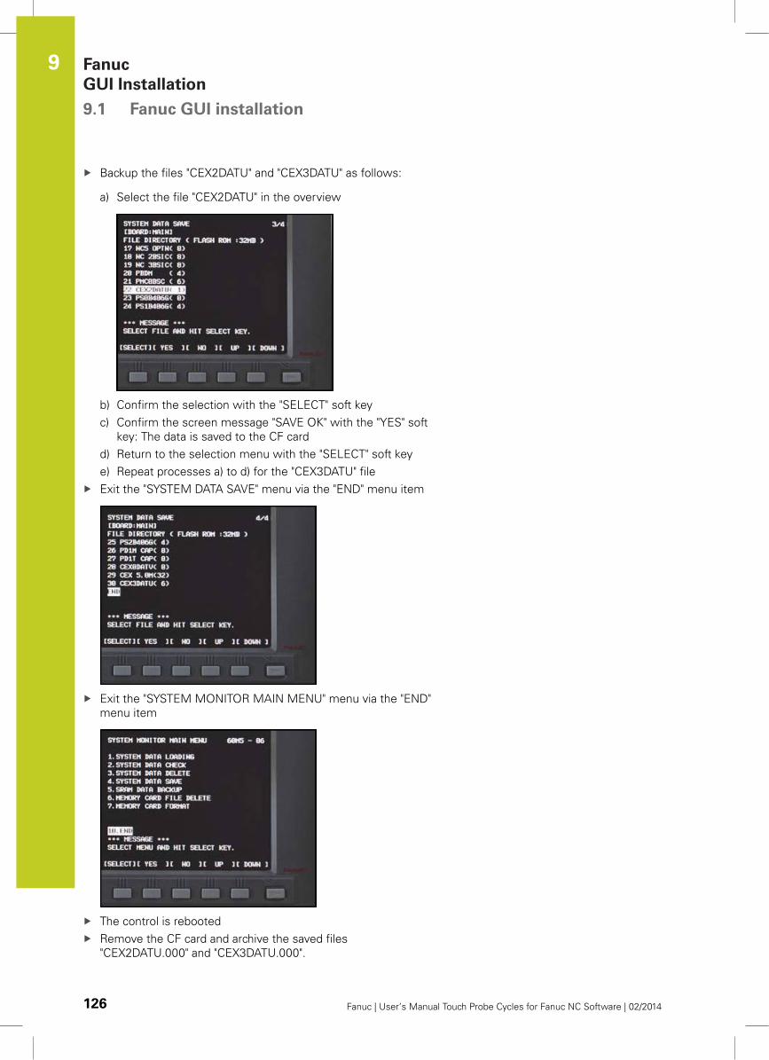
Fanuc
GUI Installation 9.1 Fanuc GUI installation
9
126 Fanuc | User’s Manual Touch Probe Cycles for Fanuc NC Software | 02/2014
Backup the files "CEX2DATU" and "CEX3DATU" as follows:
a) Select the file "CEX2DATU" in the overview
b) Confirm the selection with the "SELECT" soft key
c) Confirm the screen message "SAVE OK" with the "YES" soft
key: The data is saved to the CF card
d) Return to the selection menu with the "SELECT" soft key
e) Repeat processes a) to d) for the "CEX3DATU" file
Exit the "SYSTEM DATA SAVE" menu via the "END" menu item
Exit the "SYSTEM MONITOR MAIN MENU" menu via the "END"
menu item
The control is rebooted
Remove the CF card and archive the saved files
"CEX2DATU.000" and "CEX3DATU.000".
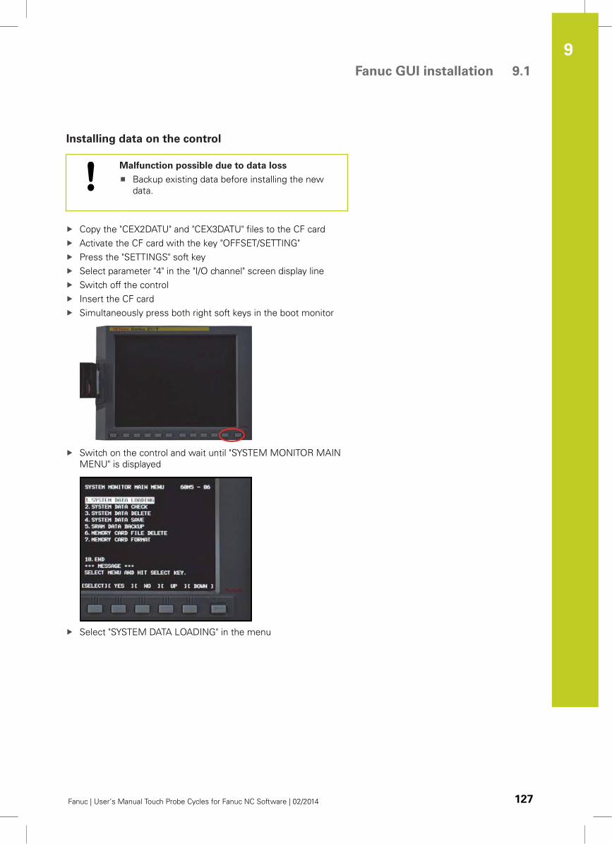
Fanuc GUI installation 9.1
9
Fanuc | User’s Manual Touch Probe Cycles for Fanuc NC Software | 02/2014 127
Installing data on the control
Malfunction possible due to data loss
Backup existing data before installing the new
data.
Copy the "CEX2DATU" and "CEX3DATU" files to the CF card
Activate the CF card with the key "OFFSET/SETTING"
Press the "SETTINGS" soft key
Select parameter "4" in the "I/O channel" screen display line
Switch off the control
Insert the CF card
Simultaneously press both right soft keys in the boot monitor
Switch on the control and wait until "SYSTEM MONITOR MAIN
MENU" is displayed
Select "SYSTEM DATA LOADING" in the menu
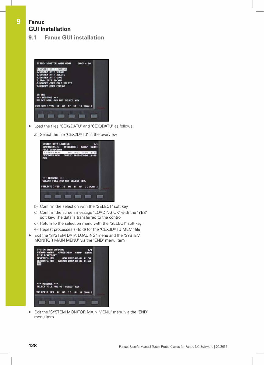
Fanuc
GUI Installation 9.1 Fanuc GUI installation
9
128 Fanuc | User’s Manual Touch Probe Cycles for Fanuc NC Software | 02/2014
Load the files "CEX2DATU" and "CEX3DATU" as follows:
a) Select the file "CEX2DATU" in the overview
b) Confirm the selection with the "SELECT" soft key
c) Confirm the screen message "LOADING OK" with the "YES"
soft key. The data is transferred to the control
d) Return to the selection menu with the "SELECT" soft key
e) Repeat processes a) to d) for the "CEX3DATU MEM" file
Exit the "SYSTEM DATA LOADING" menu and the "SYSTEM
MONITOR MAIN MENU" via the "END" menu item
Exit the "SYSTEM MONITOR MAIN MENU" menu via the "END"
menu item
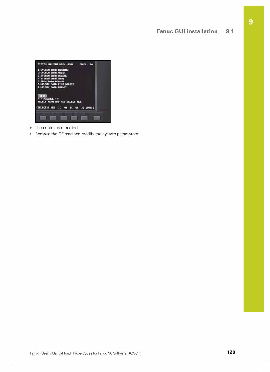
Fanuc GUI installation 9.1
9
Fanuc | User’s Manual Touch Probe Cycles for Fanuc NC Software | 02/2014 129
The control is rebooted
Remove the CF card and modify the system parameters
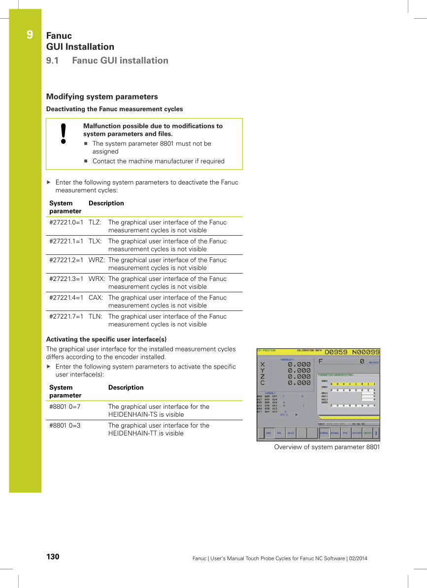
Fanuc
GUI Installation 9.1 Fanuc GUI installation
9
130 Fanuc | User’s Manual Touch Probe Cycles for Fanuc NC Software | 02/2014
Modifying system parameters
Deactivating the Fanuc measurement cycles
Malfunction possible due to modifications to
system parameters and files.
The system parameter 8801 must not be
assigned
Contact the machine manufacturer if required
Enter the following system parameters to deactivate the Fanuc
measurement cycles:
System
parameter
Description
#27221.0=1 TLZ: The graphical user interface of the Fanuc
measurement cycles is not visible
#27221.1=1 TLX: The graphical user interface of the Fanuc
measurement cycles is not visible
#27221.2=1 WRZ: The graphical user interface of the Fanuc
measurement cycles is not visible
#27221.3=1 WRX: The graphical user interface of the Fanuc
measurement cycles is not visible
#27221.4=1 CAX: The graphical user interface of the Fanuc
measurement cycles is not visible
#27221.7=1 TLN: The graphical user interface of the Fanuc
measurement cycles is not visible
Activating the specific user interface(s)
The graphical user interface for the installed measurement cycles
differs according to the encoder installed.
Enter the following system parameters to activate the specific
user interface(s):
System
parameter
Description
#8801 0=7 The graphical user interface for the
HEIDENHAIN-TS is visible
#8801 0=3 The graphical user interface for the
HEIDENHAIN-TT is visible
Overview of system parameter 8801
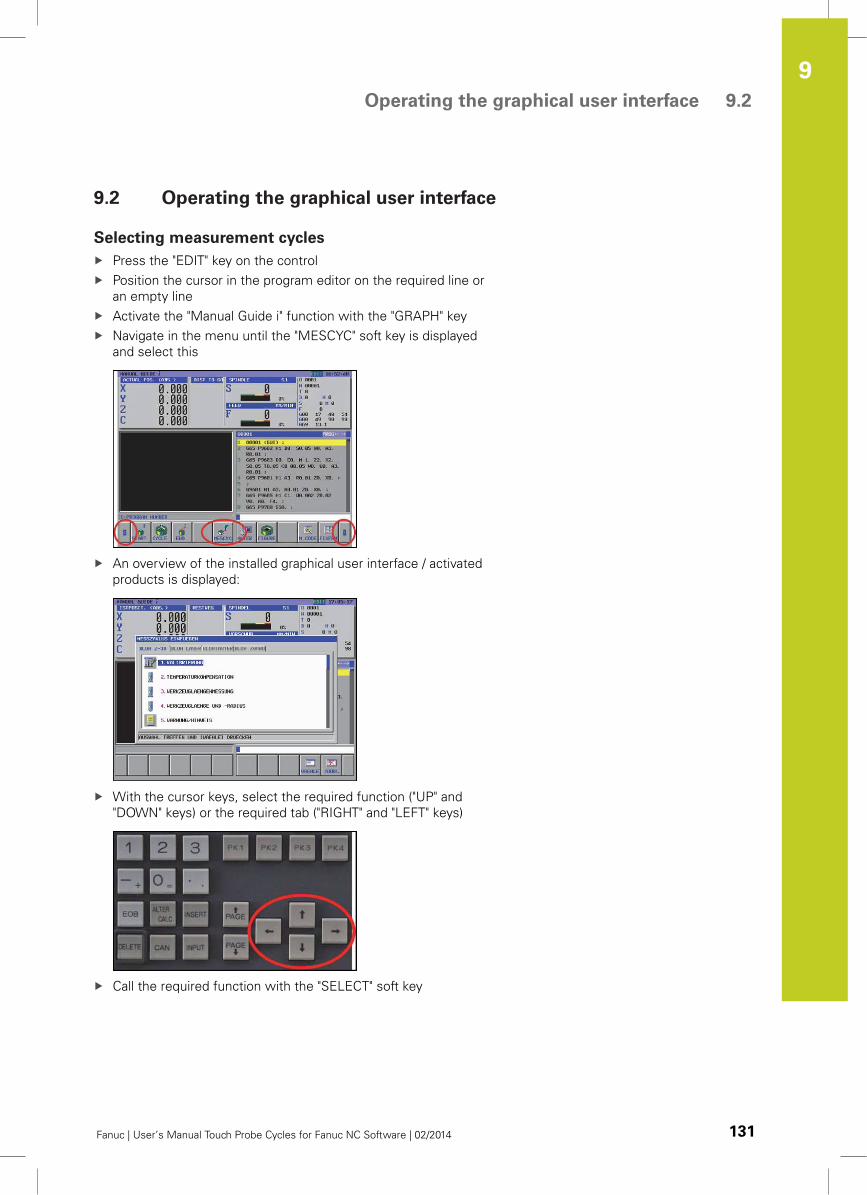
Operating the graphical user interface 9.2
9
Fanuc | User’s Manual Touch Probe Cycles for Fanuc NC Software | 02/2014 131
9.2 Operating the graphical user interface
Selecting measurement cycles
Press the "EDIT" key on the control
Position the cursor in the program editor on the required line or
an empty line
Activate the "Manual Guide i" function with the "GRAPH" key
Navigate in the menu until the "MESCYC" soft key is displayed
and select this
An overview of the installed graphical user interface / activated
products is displayed:
With the cursor keys, select the required function ("UP" and
"DOWN" keys) or the required tab ("RIGHT" and "LEFT" keys)
Call the required function with the "SELECT" soft key
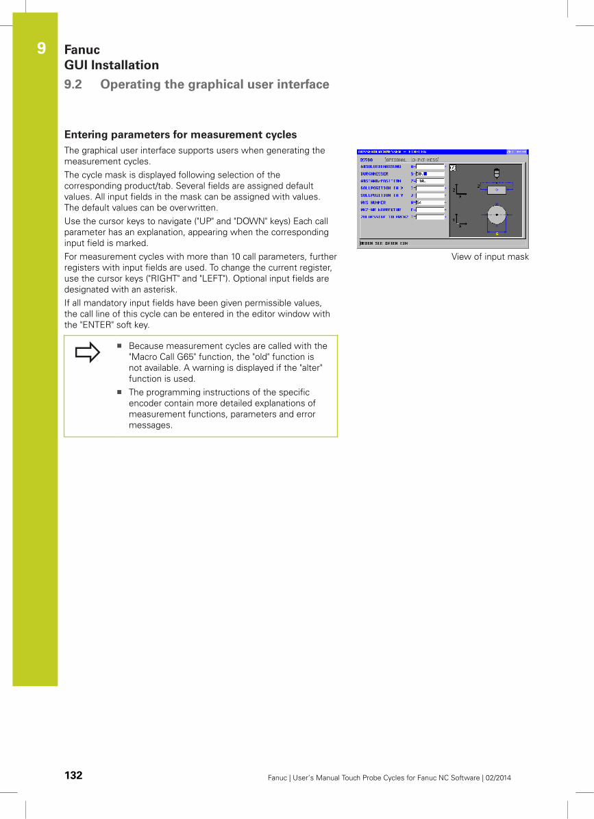
Fanuc
GUI Installation 9.2 Operating the graphical user interface
9
132 Fanuc | User’s Manual Touch Probe Cycles for Fanuc NC Software | 02/2014
Entering parameters for measurement cycles
The graphical user interface supports users when generating the
measurement cycles.
The cycle mask is displayed following selection of the
corresponding product/tab. Several fields are assigned default
values. All input fields in the mask can be assigned with values.
The default values can be overwritten.
Use the cursor keys to navigate ("UP" and "DOWN" keys) Each call
parameter has an explanation, appearing when the corresponding
input field is marked.
For measurement cycles with more than 10 call parameters, further
registers with input fields are used. To change the current register,
use the cursor keys ("RIGHT" and "LEFT"). Optional input fields are
designated with an asterisk.
If all mandatory input fields have been given permissible values,
the call line of this cycle can be entered in the editor window with
the "ENTER" soft key.
Because measurement cycles are called with the
"Macro Call G65" function, the "old" function is
not available. A warning is displayed if the "alter"
function is used.
The programming instructions of the specific
encoder contain more detailed explanations of
measurement functions, parameters and error
messages.
View of input mask
10Error messages
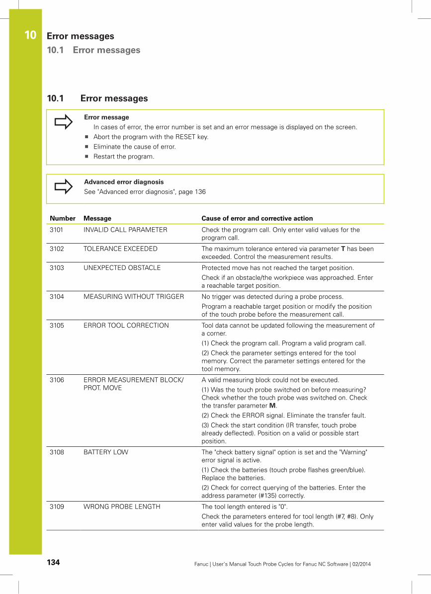
Error messages 10.1 Error messages
10
134 Fanuc | User’s Manual Touch Probe Cycles for Fanuc NC Software | 02/2014
10.1 Error messages
Error message
In cases of error, the error number is set and an error message is displayed on the screen.
Abort the program with the RESET key.
Eliminate the cause of error.
Restart the program.
Advanced error diagnosis
See "Advanced error diagnosis", page 136
Number Message Cause of error and corrective action
3101 INVALID CALL PARAMETER Check the program call. Only enter valid values for the
program call.
3102 TOLERANCE EXCEEDED The maximum tolerance entered via parameter T has been
exceeded. Control the measurement results.
3103 UNEXPECTED OBSTACLE Protected move has not reached the target position.
Check if an obstacle/the workpiece was approached. Enter
a reachable target position.
3104 MEASURING WITHOUT TRIGGER No trigger was detected during a probe process.
Program a reachable target position or modify the position
of the touch probe before the measurement call.
3105 ERROR TOOL CORRECTION Tool data cannot be updated following the measurement of
a corner.
(1) Check the program call. Program a valid program call.
(2) Check the parameter settings entered for the tool
memory. Correct the parameter settings entered for the
tool memory.
3106 ERROR MEASUREMENT BLOCK/
PROT. MOVE
A valid measuring block could not be executed.
(1) Was the touch probe switched on before measuring?
Check whether the touch probe was switched on. Check
the transfer parameter M.
(2) Check the ERROR signal. Eliminate the transfer fault.
(3) Check the start condition (IR transfer, touch probe
already deflected). Position on a valid or possible start
position.
3108 BATTERY LOW The "check battery signal" option is set and the "Warning"
error signal is active.
(1) Check the batteries (touch probe flashes green/blue).
Replace the batteries.
(2) Check for correct querying of the batteries. Enter the
address parameter (#135) correctly.
3109 WRONG PROBE LENGTH The tool length entered is "0".
Check the parameters entered for tool length (#7, #8). Only
enter valid values for the probe length.
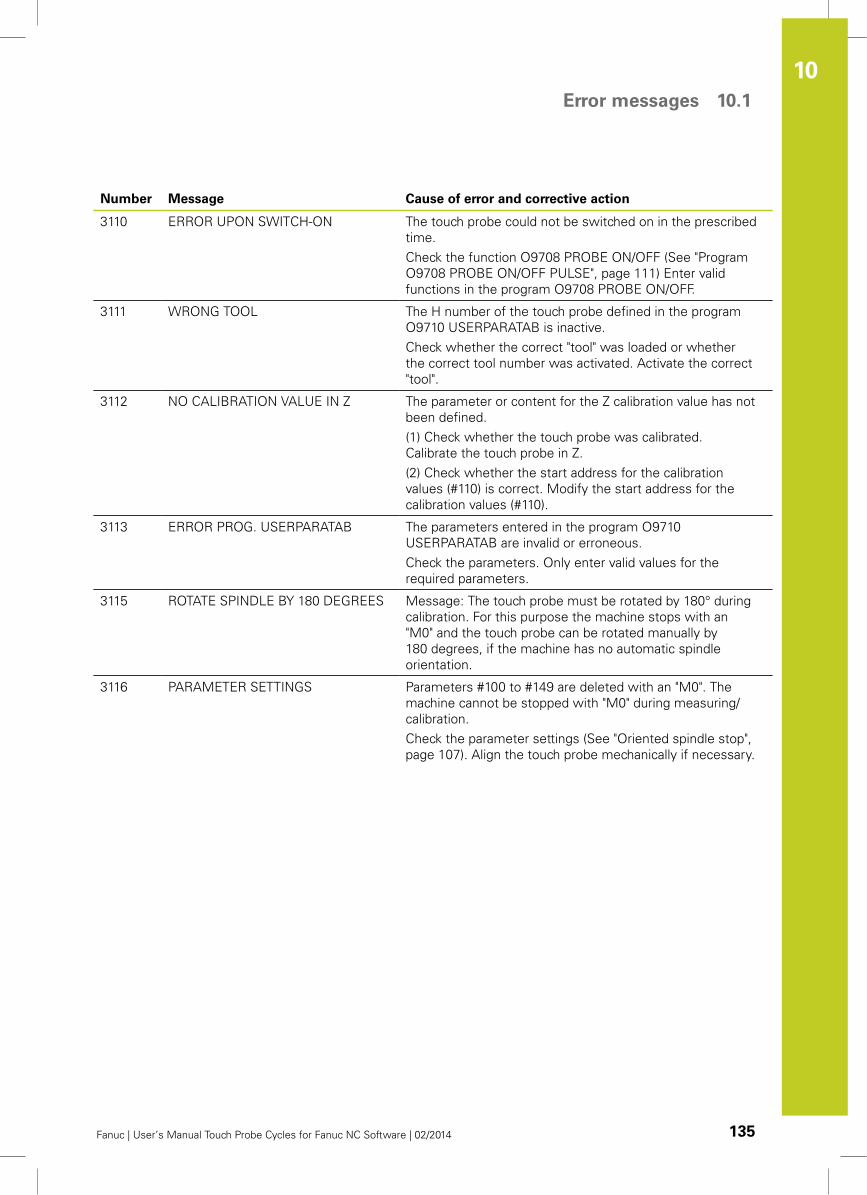
Error messages 10.1
10
Fanuc | User’s Manual Touch Probe Cycles for Fanuc NC Software | 02/2014 135
Number Message Cause of error and corrective action
3110 ERROR UPON SWITCH-ON The touch probe could not be switched on in the prescribed
time.
Check the function O9708 PROBE ON/OFF (See "Program
O9708 PROBE ON/OFF PULSE", page 111) Enter valid
functions in the program O9708 PROBE ON/OFF.
3111 WRONG TOOL The H number of the touch probe defined in the program
O9710 USERPARATAB is inactive.
Check whether the correct "tool" was loaded or whether
the correct tool number was activated. Activate the correct
"tool".
3112 NO CALIBRATION VALUE IN Z The parameter or content for the Z calibration value has not
been defined.
(1) Check whether the touch probe was calibrated.
Calibrate the touch probe in Z.
(2) Check whether the start address for the calibration
values (#110) is correct. Modify the start address for the
calibration values (#110).
3113 ERROR PROG. USERPARATAB The parameters entered in the program O9710
USERPARATAB are invalid or erroneous.
Check the parameters. Only enter valid values for the
required parameters.
3115 ROTATE SPINDLE BY 180 DEGREES Message: The touch probe must be rotated by 180° during
calibration. For this purpose the machine stops with an
"M0" and the touch probe can be rotated manually by
180 degrees, if the machine has no automatic spindle
orientation.
3116 PARAMETER SETTINGS Parameters #100 to #149 are deleted with an "M0". The
machine cannot be stopped with "M0" during measuring/
calibration.
Check the parameter settings (See "Oriented spindle stop",
page 107). Align the touch probe mechanically if necessary.
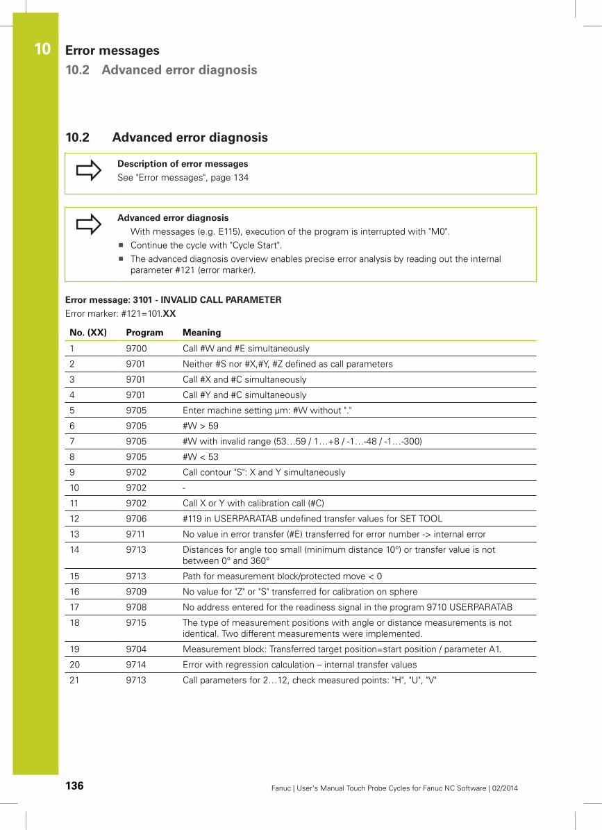
Error messages 10.2 Advanced error diagnosis
10
136 Fanuc | User’s Manual Touch Probe Cycles for Fanuc NC Software | 02/2014
10.2 Advanced error diagnosis
Description of error messages
See "Error messages", page 134
Advanced error diagnosis
With messages (e.g. E115), execution of the program is interrupted with "M0".
Continue the cycle with "Cycle Start".
The advanced diagnosis overview enables precise error analysis by reading out the internal
parameter #121 (error marker).
Error message: 3101 - INVALID CALL PARAMETER
Error marker: #121=101.XX
No. (XX) Program Meaning
1 9700 Call #W and #E simultaneously
2 9701 Neither #S nor #X,#Y, #Z defined as call parameters
3 9701 Call #X and #C simultaneously
4 9701 Call #Y and #C simultaneously
5 9705 Enter machine setting µm: #W without "."
6 9705 #W > 59
7 9705 #W with invalid range (53…59 / 1…+8 / -1…-48 / -1…-300)
8 9705 #W < 53
9 9702 Call contour "S": X and Y simultaneously
10 9702 -
11 9702 Call X or Y with calibration call (#C)
12 9706 #119 in USERPARATAB undefined transfer values for SET TOOL
13 9711 No value in error transfer (#E) transferred for error number -> internal error
14 9713 Distances for angle too small (minimum distance 10°) or transfer value is not
between 0° and 360°
15 9713 Path for measurement block/protected move < 0
16 9709 No value for "Z" or "S" transferred for calibration on sphere
17 9708 No address entered for the readiness signal in the program 9710 USERPARATAB
18 9715 The type of measurement positions with angle or distance measurements is not
identical. Two different measurements were implemented.
19 9704 Measurement block: Transferred target position=start position / parameter A1.
20 9714 Error with regression calculation – internal transfer values
21 9713 Call parameters for 2…12, check measured points: "H", "U", "V"
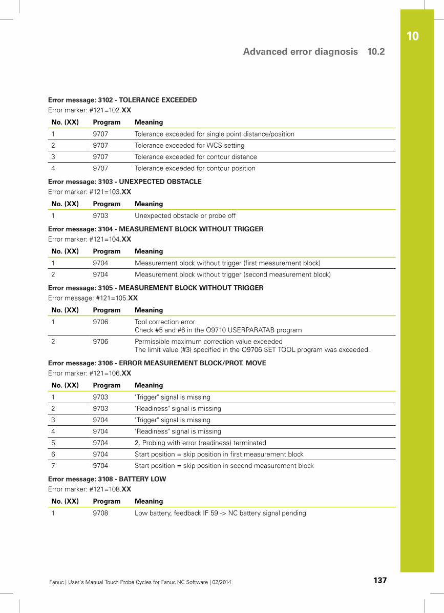
Advanced error diagnosis 10.2
10
Fanuc | User’s Manual Touch Probe Cycles for Fanuc NC Software | 02/2014 137
Error message: 3102 - TOLERANCE EXCEEDED
Error marker: #121=102.XX
No. (XX) Program Meaning
1 9707 Tolerance exceeded for single point distance/position
2 9707 Tolerance exceeded for WCS setting
3 9707 Tolerance exceeded for contour distance
4 9707 Tolerance exceeded for contour position
Error message: 3103 - UNEXPECTED OBSTACLE
Error marker: #121=103.XX
No. (XX) Program Meaning
1 9703 Unexpected obstacle or probe off
Error message: 3104 - MEASUREMENT BLOCK WITHOUT TRIGGER
Error marker: #121=104.XX
No. (XX) Program Meaning
1 9704 Measurement block without trigger (first measurement block)
2 9704 Measurement block without trigger (second measurement block)
Error message: 3105 - MEASUREMENT BLOCK WITHOUT TRIGGER
Error message: #121=105.XX
No. (XX) Program Meaning
1 9706 Tool correction error
Check #5 and #6 in the O9710 USERPARATAB program
2 9706 Permissible maximum correction value exceeded
The limit value (#3) specified in the O9706 SET TOOL program was exceeded.
Error message: 3106 - ERROR MEASUREMENT BLOCK/PROT. MOVE
Error marker: #121=106.XX
No. (XX) Program Meaning
1 9703 "Trigger" signal is missing
2 9703 "Readiness" signal is missing
3 9704 "Trigger" signal is missing
4 9704 "Readiness" signal is missing
5 9704 2. Probing with error (readiness) terminated
6 9704 Start position = skip position in first measurement block
7 9704 Start position = skip position in second measurement block
Error message: 3108 - BATTERY LOW
Error marker: #121=108.XX
No. (XX) Program Meaning
1 9708 Low battery, feedback IF 59 -> NC battery signal pending
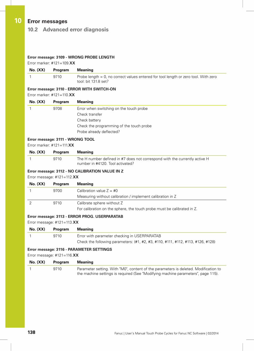
Error messages 10.2 Advanced error diagnosis
10
138 Fanuc | User’s Manual Touch Probe Cycles for Fanuc NC Software | 02/2014
Error message: 3109 - WRONG PROBE LENGTH
Error marker: #121=109.XX
No. (XX) Program Meaning
1 9710 Probe length = 0, no correct values entered for tool length or zero tool. With zero
tool: bit 131.8 set?
Error message: 3110 - ERROR WITH SWITCH-ON
Error marker: #121=110.XX
No. (XX) Program Meaning
1 9708 Error when switching on the touch probe
Check transfer
Check battery
Check the programming of the touch probe
Probe already deflected?
Error message: 3111 - WRONG TOOL
Error marker: #121=111.XX
No. (XX) Program Meaning
1 9710 The H number defined in #7 does not correspond with the currently active H
number in #4120. Tool activated?
Error message: 3112 - NO CALIBRATION VALUE IN Z
Error message: #121=112.XX
No. (XX) Program Meaning
1 9700 Calibration value Z = #0
Measuring without calibration / implement calibration in Z
2 9710 Calibrate sphere without Z
For calibration on the sphere, the touch probe must be calibrated in Z.
Error message: 3113 - ERROR PROG. USERPARATAB
Error message: #121=113.XX
No. (XX) Program Meaning
1 9710 Error with parameter checking in USERPARATAB
Check the following parameters: (#1, #2, #3, #110, #111, #112, #113, #126, #128)
Error message: 3116 - PARAMETER SETTINGS
Error message: #121=116.XX
No. (XX) Program Meaning
1 9710 Parameter setting. With "M0", content of the parameters is deleted. Modification to
the machine settings is required (See "Modifying machine parameters", page 115).
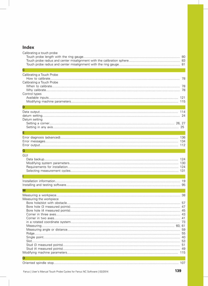
Fanuc | User’s Manual Touch Probe Cycles for Fanuc NC Software | 02/2014 139
Index
Calibrating a touch probe
Touch probe length with the ring gauge............................................................................................................. 80
Touch probe radius and center misalignment with the calibration sphere.......................................................... 83
Touch probe radius and center misalignment with the ring gauge..................................................................... 81
C
Calibrating a Touch Probe
How to calibrate.................................................................................................................................................. 78
Calibrating a Touch Probe
When to calibrate................................................................................................................................................ 78
Why calibrate....................................................................................................................................................... 78
Control types
Available inputs.................................................................................................................................................. 121
Modifying machine parameters......................................................................................................................... 115
D
Data output............................................................................................................................................................ 114
datum setting........................................................................................................................................................... 24
Datum setting
Setting a corner............................................................................................................................................. 26, 27
Setting in any axis.............................................................................................................................................. 25
E
Error diagnosis (advanced)..................................................................................................................................... 136
Error messages...................................................................................................................................................... 134
Error output............................................................................................................................................................ 112
G
GUI
Data backup....................................................................................................................................................... 124
Modifying system parameters........................................................................................................................... 130
Requirements for installation............................................................................................................................. 124
Selecting measurement cycles.......................................................................................................................... 131
I
Installation information............................................................................................................................................. 19
Installing and testing software................................................................................................................................. 95
M
Measuring a workpiece............................................................................................................................................ 38
Measuring the workpiece
Bore hole/slot with obstacle................................................................................................................................ 57
Bore hole (3 measured points)............................................................................................................................ 47
Bore hole (4 measured points)............................................................................................................................ 45
Corner in three axes............................................................................................................................................ 43
Corner in two axes.............................................................................................................................................. 41
in a rotated coordinate system........................................................................................................................... 73
Measuring...................................................................................................................................................... 60, 61
Measuring angle or distance............................................................................................................................... 59
Ridge.................................................................................................................................................................... 55
Single point.......................................................................................................................................................... 40
Slot....................................................................................................................................................................... 53
Stud (3 measured points).................................................................................................................................... 51
Stud (4 measured points).................................................................................................................................... 49
Modifying machine parameters............................................................................................................................. 115
O
Oriented spindle stop............................................................................................................................................. 107
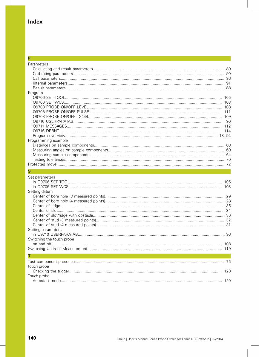
Index
140 Fanuc | User’s Manual Touch Probe Cycles for Fanuc NC Software | 02/2014
P
Parameters
Calculating and result parameters....................................................................................................................... 89
Calibrating parameters......................................................................................................................................... 90
Call parameters.................................................................................................................................................... 86
Internal parameters.............................................................................................................................................. 91
Result parameters................................................................................................................................................ 88
Program
O9706 SET TOOL.............................................................................................................................................. 105
O9706 SET WCS............................................................................................................................................... 103
O9708 PROBE ON/OFF LEVEL......................................................................................................................... 108
O9708 PROBE ON/OFF PULSE........................................................................................................................ 111
O9708 PROBE ON/OFF TS444......................................................................................................................... 109
O9710 USERPARATAB......................................................................................................................................... 96
O9711 MESSAGES............................................................................................................................................ 112
O9716 DPRNT................................................................................................................................................... 114
Program overview.......................................................................................................................................... 18, 94
Programming example
Distances on sample components...................................................................................................................... 68
Measuring angles on sample components......................................................................................................... 69
Measuring sample components.......................................................................................................................... 64
Testing tolerances................................................................................................................................................ 70
Protected move........................................................................................................................................................ 72
S
Set parameters
in O9706 SET TOOL.......................................................................................................................................... 105
in O9706 SET WCS........................................................................................................................................... 103
Setting datum
Center of bore hole (3 measured points)............................................................................................................ 29
Center of bore hole (4 measured points)............................................................................................................ 28
Center of ridge.................................................................................................................................................... 35
Center of slot....................................................................................................................................................... 34
Center of slot/ridge with obstacle....................................................................................................................... 36
Center of stud (3 measured points).................................................................................................................... 32
Center of stud (4 measured points).................................................................................................................... 31
Setting parameters
in O9710 USERPARATAB..................................................................................................................................... 96
Switching the touch probe
on and off.......................................................................................................................................................... 108
Switching Units of Measurement.......................................................................................................................... 119
T
Test component presence....................................................................................................................................... 75
touch probe
Checking the trigger.......................................................................................................................................... 120
Touch probe
Autostart mode.................................................................................................................................................. 120