for the national aero-space plane - nasa · for the national aero-space plane by ... research...
TRANSCRIPT

NASA Technical Memorandum 107728
//t/_ o 2..----_
n/3
AN OVERVIEW OF AEROELASTICITY STUDIESFOR THE NATIONAL AERO-SPACE PLANE
Rodney H. RickettsThomas E. NollWoodrow Whitlow Jr,Lawrence J. Huttsell
March 1993
(NASA-TM-I07728) AN OVERVIEW OF
_EROELASTICITY STUDIES FOR THE
NATIONAL AEROSPACE PLANE (NASA)
13 p
N93-23422
Unc1 as
G3/02 0158557
NASANational Aeronautics andSpace Administration
Langley I_searoh CenterHampton, Virginia 23665
https://ntrs.nasa.gov/search.jsp?R=19930014233 2018-08-20T23:14:54+00:00Z

ii
ii!
=

AN OVERVIEW OF AEROELASTICITY STUDIESFOR THE NATIONAL AERO-SPACE PLANE
byRodney H. Ricketts*, Thomas E. Noll**, Woodrow Whitlow, Jr. t
NASA Langley Research Center
Lawrence J. Huttsell tt
USAF Wright Laboratory
Abstract
The National Aero-Space Plane (NASP), or X-30, isa single-stage-to-orbit vehicle that is designed to takeoffand land on conventional runways. Research inaeroelasticity was conducted by the NASA LangleyResearch Center and the USA/: Wright Laboratory tosupport the design of a flight vehicle by the nationalcontractor team. This research includes the development ofnew computational codes for predicting unsteadyaerodynamic pressures. In addition, studies were conductedto determine the aerodynamic heating effects on vehicleaeroelasticity and to determine the effects of fuselageflexibility on the stability of the control systems. It alsoincludes the testing of scale models to better understand theaeroelastic behavior of the X-30 and to obtain data for codevalidation and correlation. This paper presents an overviewof the aeroelastie research which has been conducted tosupport the airframe design.
I. Introduction
The National Aero-Space Plane (NASP), or X-30, isa single-stage-to-orbit vehicle that is designed to takeoffand land on conventional runways. An artist concept of aNASP vehicle is shown in figure 1. A vehicle thataccomplishes the mission requires a minimum-weightstructure that is capable of withstanding large temperaturechanges. These requirements lead to a vehicle structurethat has inherent flexibilities and is susceptible to stiffnessreductions due to thermal loads and gradients. Thesestiffness reductions, in turn, may lead to a degradation inthe aeroelastic stability of the vehicle. Beginning in 1987some experimental and analytical studies were conducted toassess the aeroelastic characteristics of the NASP vehicleand to validate the computational tools that are used in itsdesign.
* Head, Configuration Aeroelasticity Branch,Structural Dynamics Division; Senior Member, AIAA
Head, Aeroservoelasticity Branch, Smacturai
D_namics Division; Associate Fellow, AIAAHead, Unsteady Aerodynamics Branch, Smactural
Dynamics Division; Senior Member,/dAAtT Aerospace Engineer, Aeroelastic Section,
Structures Division; Associate Fellow, AIAA
Initial studies in aeroelasticity of NASP-Iike vehicleswere performed under the Technology Maturation Plan(TMP) and mainly focused on three areas: increasing andvalidating unsteady aerodynamics and aeroelastic analysiscapabilities to meet NASP needs; expanding integratedanalysis methodology to include thermal effects and activecontrol technology; and, developing an experimental database for a better understanding of the aeroelastic responsecharacteristics of NASP-Iike vehicles. Selected resultsfrom efforts in these three areas are presented in figures 2-4and are described in reference 1.
Beginning in 1991 the research was restructuredaccording to Government Work Packages (GWP) and to beperformed by government agencies in direct support of thenational contractor team which is designing the NASP X-30 vehicle. The work that is reported herein wasaccomplished by the NASA Langley Research Center andthe USAF Wright Laboratory. It encompasses bothanalytical and experimental studies of the complete vehicle,as well as its components, such as lifting surfaces andfuselage panels, to determine and evaluate its fluttercharacteristics. Furthermore, the work involvesdevelopment and validation of advanced methods forpredicting unsteady aerodynamic forces andaeroservothermoelastic instabilities. An overview of the
efforts in each of these areas is presented in this paper.The purposes of the paper are to indicate the scope of thetechnical work which has been performed in these areas andto introduce the technical papers which present the detailsof the work in two special sessions on Aero-Space Planeaeroelasticity at the 34th/dAb. SDM Conference.
Figure I. Artist concept of NASP X-30 vehicle.

-New FPE finite-volume formulation completed
-FLOE method permits use of body-fitted grids
-2D method coded to demonstrate capability
NACA 0012 Airfoil at M=0.75, (x=2"
+!o°%7 o×/c
Figure 2. Full potential flow and Euler analysis ofNACA0012 airfoil.
II. Demonstrator VehiCle
The NASP X-30 vehicle which is shown in figure 1has a large fuselage with hydrogen-fuel internal tanks,clipped double-delta wings with trailing-edge elevons forroll and pitch control, and vertical fins for lateral stability.For purposes of the GWP studies, this vehicle wasmodified to include all-moveable clipped delta wings forpitch and roll control. Drawings of the planform and sideprofile of the modified vehicle, named the Demonstrator
Vehicle, are shown in figure 5. A NASTRAN structural
finite element model 2 of this vehicle was developed and
used in the studies. It is shown in figure 6. A typicalflight trajectory for this vehicle is shown in figure 7.
Vm'th_l Fin
F.nEouJatry IUP_OWMSVr
TO4
I 10 |m
q!
qt'--'_h0
0.0
Hm Clem¢l
"SN I.=sa _
_ .= op,_•
2 4
Figure 3. Ride quality and flutter suppression results of ageneric NASP design.
III. Analytical Studies
Major efforts have been undertaken to develop newand enhanced computational codes for accurate predictionsof unsteady aerodynamic loads and effects of thermal
heating on the structure. The research in these area aredescribed in this section.
FLUTTER AND DIVERGENCE OF ALL-MOVEABLEDELTA WING DETERMINED
MODEL IN TDT
F_exibie - =5_
",.,_, "6 MAC
FLUTTER BOUNDARY DIVERGENCEPtVOTA T 375 MAC PIVOT A T 6 MAC
LO0, _ . Unstabte 300FTesl n...." t-, " + -- r_";Tn_°',t
'n m,. 150. -+s +++_:-- -, ". 200o,.+ t o,°++{llpress,j_e. _OOtT` _Stable pressure. | _. I
0 .5 10 0 •Macl_ r_o
Figure 4. Experimental/analytical results of simple all-moveable wing tests in TDT.
Unsteady aerodynamics
The unsteady aerodynamics effort has the goal ofdeveloping computational methods for unsteadyaerodynamic and aeroelastic analyses of the NASP over itsflight envelope. This was accomplished by assessing thestate-of-the-art codes and by modifying three existingcomputational fluid dynamics (CFD) codes to allowaccurate analysis of NASP-Iike vehicles. The modified
codes are the CAP-TSD (Computational AeroelasticityProgram - Transonic Small Disturbance) aeroelasticanalysis code which uses transonic small disturbance
(TSD) potential aerodynamics and the CFL3D andENS3DAE codes which use Euler/Navier-Stokes
aerodynamics. The Euler/Navier-Stokes codes provideanalysis capabilities for all speed ranges, and CAP-TSD isused for transonic analysis. This section presents anassessment of state-of-the-art codes and a description of thenew analysis capabilities which were obtained bymodifying CAP-TSD and CFL3D to allow aeroelasticanalysis of a NASP-Iike vehicle. In addition some selected
results are presented.
All-Moveable Wing
Pivot
Figure 5. Prof'de and planform of Demonstrator Vehicle.

State-of-the-art codes. The NASP vehicle in its
ascent trajectory will be required to fly through anextraordinarily large range of Mach number conditions asindicated by the flight profile shown in figure 7.Therefore, a variety of existing computer codes associatedwith aeroelastic analyses were assessed. Codes associatedwith modeling the aerodynamic shape, calculating vehiclesurface temperature distributions, developing finite elementmodels with aerodynamic heating effects included,conducting steady, unsteady, and nonlinear aerodynamicanalyses, performing linear aeroelastic analyses, anddesigning and analyzing control systems were considered.These codes, with recommendations on their usefulness inmeeting the GWP objectives, are described in reference 3.A summary of the assessment of the aerodynamic codesfollows.
and a fuselage flexibility were required for aeroelasticanalysis of a Demonstrator Vehicle; such a vehicle has aflexible, lifting fuselage and flexible, swept, verticalsurfaces.
300,000
200,000
"- 100,000
00 10 20 30
Mach Number
Figure 6. Structural finite element model of NASPDemonstrator Vehicle.
Presendy, reliable and accurate linear lifting surfacetheories exist for predicting unsteady aerodynamic forcesand performing flutter analyses for general configurationsat subsonic Mach numbers up to about 0.95 and atsupersonic Mach numbers from 1.05 to about 3. ForMach numbers from about 3 to 10, simple linear methodssuch as Van Dyke's second-order piston theory andNewtonian impact theory can be used to predict theunsteady aerodynamic forces. However, for Mach numbersabove 10, the validity of using these simple methods isquestionable because of the presence of severe shockinteractions, unusual flow phenomena, and chemicallyreacting gases. The aerodynamic codes used in this studyand their range of applicability are summarized in figure 8.
CAP-TSD. The CAP-TSD code was developed at theNASA Langley Research Center and has been used to
predict wing flutter 4 accurately and to model nearly
complete aircraft configurations5, 6. It can be used foranalysis of flight vehicles with an arbitrary number ofhorizontal lifting surfaces, vertical surfaces, and bodies.The original code only could be used for analysis ofvehicles with rigid fuselages and vehicles with verticalsurfaces that were rigid and had rectangular planforrns. Theadditions of a flexible, swept, vertical surface capability
Figure 7. Representative ascent trajectory.
Calculations that demonstrate the capabilities of theCAP-TSD code are presented next. They includecalculations for the following configurations: the AGARDT-tail, a slender fuselage, and a NASP vehicle. Figure 9shows unsteady lifting pressures on the AGARD T-tail forthe vertical fin oscillating in twist at M = 0.8 and k = 1.5.(The T-tail configuration is shown at the upper left of thefigure.) Results are shown for three spanwise stations--oneon the vertical fin at 65-percent of semispan, one on thehorizontal stabilizer near the junction of the fin andstabilizer (five-percent semi-span), and one at 55-percentsemi-span of the stabilizer. The unsteady motion producessignificant interference effects on the horizontal stabilizer,especially near the fin-tail junction, as shown in the upperright of figure 9. The effects of the vertical fin leading-edge singularity on the solution also can be seen in thepressures at the fin-tail junction. Comparisons with thedoublet-lattice aerodynamic method 7 in the ISAC
(Interaction of Structures, Aerodynamics, and Controls) 8code show good agreement.
Doublet Lattice
f Transonic Region,,_m ,m,_ Harmonic Gradient (ZONA)
i van Dyke's 2nd-Order Piston Theory
i Nswtonlan Impact Theory
Blended Piston and Ne_onlan Impact Theories_ p
_ I I I I I I I I I5 10
Mach Number
Figure 8. Aerodynamic theories used for fluttercalculations.

Calculations of steady pressures on a slender fuselagewith circular cross sections are presented next. Figure 10shows a comparison of calculated and measured steady
surface pressure coefficients Cp along the top and bottomof the fuselage for M -- 0.99 and an angle of attack of 8.4 °.For this case a shock wave exists around the fuselage near
the 80-percent chord line. The pressures calculated usingCAP-TSD show very good agreement with theexperimental data from reference 9.
Figure 1 ! shows the calculated pressures along thetop and bottom centerlines of the NASP fuselage for M =0.9 and an angle of attack of 0 degrees. The pressuredistribution is relatively smooth along the top of thevehicle, but along the bottom, the pressure distributionshows rapid expansion at the engine inlet and at the aft end
of the engine assembly. Surface pressure contours for thiscase are shown in figure 12.
6° f3.0
ACp o.oI o ,.,o---3.0_--6.0_
0.0 lO oo lOx/c x/c
conforms to the aeroelastically deformed shape of thevehicle. Because the aeroelastic motions may be arbitrary,
a general mesh updating procedure is necessary. Thisprocedure which was incorporated into CFL3D is onewhich models the mesh as a network of springs and solvesthe static equilibrium equations for this network to
determine the new locations of the mesh grid points 11,12.
-Cp
0.2 /'-O.l O0 '4_ll _/y
0.0 )
-0.1
-0.2 _Experiment CAP-TSD
- 0.3 O Top[3 - - - Bottom
- 0.40.0 0.2 0.4 0.6 0.8 !.0
Figure 10. Steady pressure distributions along slendercircular fuselage.
The aeroelastic equations of motion which areincorporated within CFL3D are similar to those describedin references 4 and 12. The dynamic equations of motionare formulated in terms of generalized displacements. Afterexciting the vehicle structure, damping and frequencycharacteristics of the aeroelastic responses are estimatedfrom the response curves by using the modal identification
technique of Bennett and Desmarais 13. Damping estimatesare used to determine zero-damping values (fluuer points).
Figure 9. Unsteady pressure distributions on AGARDT-tail configuration.
3.0--
--Top Centerline-4_-Bottom Centerline
The comparisons of calculations with standard
analysis methods and experimental data show that theswept, flexible, vertical surface and flexible fuselagecapabilities were formulated and implemented correctly inthe CAP-TSD code. This indicates that the modified code
is suitable for unsteady aerodynamic and aeroelasticanalyses of NASP-like vehicles.
CF"L3D. CFL3D is a CF"D code that was developed
at the NASA Langley Research Center to solve the time-
dependent Euler and thin-layer Navier-Stokes equations. 10
Its original algorithm contained the necessary metric termsfor calculating unsteady flows that required only rigidlytranslating and rotating meshes that moved withoutdeforming. In time-marching aeroelastic calculations, themesh must be updated at every time level so that it
2.0
--1.0
Figure I 1. Steady pressures along the centerline of NASPfuselage.

Figure 12. Surface pressure contours on NASP vehicle.
Figure 13 shows the aerodynamic grid and steadypressure contours on a NASP wing calculated using theEuler equations for M = 5, (x = 2.2 °. Figure 14 shows thesurface pressure coefficients on the root chord section ofthe NASP wing undergoing a static aeroelastic pitchdeformation of 2.2 ° at M = 5. One calculation is for thewing rotated rigidly, and the other is for the wingdeforming in a mode that simulates rigid pitch. The goodagreement between the two calculations demonstrates thatthe deforming grid method, which is necessary foraeroelastic analysis, is working correctly.
The aeroelastic analysis capability of the CFL3D codewas demonstrated by calculating the flutter characteristics
of the AGARD Wing 445.6, which was tested 14 in theTransonic Dynamics Tunnel at the NASA LangleyResearch Center. Figure 15 shows a partial view of thecomputational grid on the wing surface and symmetryplane. Comparisons of measured and calculated flutterspeeds and frequencies are shown in figure 16 (reference15). The calculations show very good agreement with themeasured data for subsonic Mach numbers. At Machnumbers higher than that for which the minimum flutterspeed occurs, the calculated flutter speeds and frequenciesare significantly higher than the measured values. Thesecharacteristics are consistent with those of other inviscid-flow flutter analyses of the 445.6 wing. The calculationsverify the aeroelastic analysis capability of the modifiedCFL3D code which now can be used for analysis of NASPvehicles.
Additionally, a quasi-steady aerodynamic approach 16based on small perturbations about the static aeroelasticshape and the use of only steady CFD aerodynamics wasdeveloped for performing hypersonic flutter analyses. For
this study the CFL3D code 17 was used. The techniqueassumes that the vehicle velocity is very high such that thereduced frequency of important flexible vehicle motions iswithin the quasi-steady range of aerodynamics. Under theseconditions, time constants of the unsteady flow are sosmall that the aerodynamics acting on the vehicle can beassumed to have no memory. The real part of thepressures are obtained from Cb"D calculations where thegrid has been deformed into the structural mode shapes.The imaginary parts of the pressure modes are obtained by
simulating the small motions of the mode shapes throughthe a transpiration boundary condition on the surfaces ofthe vehicle. By the superposition assumption, thegeneralized aerodynamic forces computed from the pressuremodes can be used to perform linear flutter analyses andaeroservoelastic modeling.
Figure 13. Aerodynamic grid and pressure contours forNASP wing upper surface at M = 50ct = 2.2 deg.
5'YIi CL C13 eLI
-o.,,-7 e.tOd oa O.Ot:So.OOV' 0.0_0_0_
o.o
cp r x/c
0_-
0.4-
i
O.B-
Figure 14. Surface pressures along root chord of NASPwing at M -- 5, ct = 2.2 deg.
At hypersonic speeds, the quasi-steady aerodynamictechnique can be used to provide more accurate andpotentially less conservative flutter predictions than themore common linear unsteady methods. The quasi-steadytechnique includes the steady nonlinear aerodynamics

effects and should result in a more realistic flutter sizing ofhypersonic vehicles and, possibly, lighter structuralweights. And, of course, the technique is much cheaperand faster than using fully unsteady CFD aerodynamics foraeroelastic calculations.
Figure 15. Partial view of computational grid on AGARDwing and symmetry plane.
Aeroservothermoelasticity
Because aerodynamic heating during high-stx_ flightthrough the atmosphere can destiffen the structure throughchanges in structural material properties and throughmaterial stress level changes caused by thermal gradients inbuilt-up structural components, significant couplingsbetween the elastic and rigid-body modes can result inlower flutter speeds, more pronounced aeroelastic responsecharacteristics, and adverse aeroservoelastic (ASE)interactions. Work in aeroservothermoelasticity (ASTE)was initiated to achieve the following objectives: (1)enhance, develop, and apply codes for performingaeroservothermoelastic evaluations; (2) assess the effectsof aerodynamic heating on the structural dynamic
characteristics of a Demonstrator Vehicle and flighttrajectory representative of the X-30; (3) conductaeroelastic and ASE analyses using a representative flightcontrol system; and, (4) define active control concepts thatcould be used to alleviate undesirable structural response orprevent aeroelastic instabilities. The fh'st three tasks have
been completed and are briefly described in this paper.More detailed descriptions of these activities are availablein references 16 and 18.
Aeroelastic analyses. Aeroelastic characteristics of
the Demonstrator Vehicle were predicted for a variety ofconfigurations and flight conditions. Symmetric andantisymmetric aeroelastic equations of motion for the
unheated vehicle were developed. Matched point flutteranalyses were performed using conventional state-of-the-artsubsonic, supersonic, and hypersonic linear unsteadyaerodynamic theories which were described above. Results
of the flutter analyses for the unheated vehicle are presentedin references 2 and 18.
0 ExperimentA Estimoted
-EFComputed0.8-
0.6
FlutterSpeedindex
0.4
0.2
0.0 ¸ I I I
Freq.Rotio
0.8
0.6
0.4
0.2
0.0 I I I0.2 0.6 1.0 1.4
Moch Number
Figure 16. Flutter speed index and frequency ratio versusMach number for AGARD wing.
For the symmetric flutter analyses, three types ofinstabilities were predicted within the Mach range from 0to 25. The boundaries of these instabilities for the
unheated Demonstrator Vehicle are shown in figure 17 forMach numbers to 10. The first instability is an unstableshort period mode. The second instability is a body-freedom-flutter mode predicted to occur at high subsonicand supersonic speeds. This instability involves acoalescence of the vehicle short period and the wing pivotmodes. The third instability is a flutter mode which is thecoalescence of the wing pivot mode with the first fuselagebending mode. For the antisymmetric flutter analyses onthe unheated vehicle, similar types of instabilities werepredicted as found for the unheated symmetric case.Additional details of these analyses can be found inreference 18.
Thermal effects. The NASP vehicle is expected to
reach extremely high temperatures as a result of

aerodynamic heating. Because of the long duration of thesehigh temperature conditions during ascent or descenttrajectories, heat soaking of the primary structuralcomponents may be a problem. These temperatures are ofconcern for aeroelastic stability because load bearingcomponents may encounter substantial structural changes.There are large areas of the vehicle that are expected to havelittle or no thermal protection and may experience largethermal gradients in the structure that could translate intoadverse thermal loads. These loads may have an adverseimpact on the vehicle trim, flutter, and flight controlcharacteristics. Because of these considerations, an ASTEanalysis procedure was developed and applied to theDemonstrator Vehicle. The results of the study arepresented in reference 18.
i / /
g o0 ,5 10
Mach Humber
Figure 17. Symmetric aeroelastic stability characteristicsof unheated Demonstrator Vehicle.
The procedure basically involves four steps. First,the vehicle's surface temperatures are calculated at varioushypersonic flight conditions at the centers of the
aerodynamic panels using the APAS code 19. Next, aninterpolation procedure is used to map the temperatures tothe dynamics finite element model node locations andelement centers. An element property interpolator outputsmaterial properties for each element based on the elementaltemperatures and tables of material properties as functionsof temperature. For reasons described in reference 18, onlythe effects of material property changes were included indeveloping the stiffness matrices of the heated vehicle.The third step involves performing vibration analyses onthe heated structure to obtain the modified modalcharacteristics. With the heated equations of motionavailable, the last step involves conducting unsteadyaerodynamic, aeroelastic, and active control systemanalyses. The instability mechanisms of the analyses ofthe heated vehicle (not shown in figure 17) are similar tothose of the unheated vehicle. However, there is somedegradation in the stability margins. The details of theheated analyses are described in reference 18.
Control system effects. A first-order state-spacemodel of the vehicle was developed to study the interaction
between the flexible structure and a pitch rate flight controlsystem. To obtain the ASE model, the symmetric open-loop aeroelastic model was modified to include an all-moveable wing control mode. Eight pairs of accelerationand pitch rate gyros were selected as the sensing devices.These sensors were judiciously placed along the fuselagenear the nose, the pilot station, the vehicle center-of-gravity position, the wing pivot (spindle), and the tailstations, and near the wing root, mid span, and wing tipstations. A baseline pitch rate control system consistingof proportional and rate feedback was also included in thefirst-order ASE model. As described above, the vehicleflight dynamics are characterized by an unstable dead-beat(zero frequency) short period mode throughout most of theflight envelope; in terms of its aeroelastic characteristics,the structural modes were predicted to be stable within theflight envelope.
Closed-loop analyses were performed to assess theeffects of the baseline controller on the unheated and heated
ASE models at several points along the ascent trajectory.This controller was found to be very effective in stabilizingthe unstable short period mode when the vehicle wasassumed to be rigid. However, the baseline controller wasinherently unstable throughout the flight trajectory whenflexible modes were added. The controller-commandedmotion of the massive all-moveable wing imparts a"ringing" motion throughout the entire structure. Thistinging motion of the structure when improperly phased bythe controller is the cause of the instability. A design ofan LQG-based (linear quadratic regulator theory), reduced-order, flight control system was able to stabilize theunstable short period mode in the presence of flexibleaircraft modes.
It can be concluded that adverse ASE interactions arehighly probable if the design of flight control systems forNASP-like vehicles doesn't take into account the highlyflexible fuselage characteristics and if it is not sufficientlyrobust to account for changes in fuel usage and changes inslructural vibration modes due to aerodynamic heating.
IV. Ex_rimental Investigations
Several laboratory and wind-tunnel experiments wereplanned to determine and understand the aeroelasticbehavior of the Demonstrator Vehicle. Test data wereobtained for correlation and validation of the analyticalcodes and methods used during the design of the vehicle.Aeroelastic models of fuselage panels, lifting surfaces andcomplete vehicle designs were developed and tested. Theseexperiments are described in this section and selectedresults are presentett
Because of the requirement for a minimum weightstructure which must cope with severe thermalenvironments, prevention of panel flutter is anotherproblem designers must face. The objectives of this effortare to develop a test fixture for flutter assessment in the

supersonicspeedregimeandtoprovide experimental datafor analytical correlation. To accomplish these objectivesa splitter plate/fixture was designed and built for the NASALangley Unitary Plan Wind Tunnel 20. The test panelswere designed to flutter in Section 1 of this tunnel (Machnumber 1.46 to 2.86).
FLOW
48"
h
- 62"-------
i
I
I
Figure 18. Front view drawing of panel flutter model testfixture.
The test configuration consists of a splitterplate/fixture and test panel. Figure 18 shows the frontview (looking across the tunnel) of the model with theoverall dimensions. A circular piece, called the "yawtable," is shown in the figure. The yaw table holds thetest panels of dimensions 15 in by 30 in. The yaw tablecan be manually set at several different yaw angles to testdifferent flow angularities without affecting the panel edgeconditions. The test panel is mounted in a frame thatsimulates fixed edge conditions; however, these edgesupports can be adjusted (unclamped and reclamped) torelieve inplane stresses due to temperature changes. Thisclamping mechanism and a separate system for applyingin-plane loads are contained in the cavity behind the yawtable. The cavity also contains a pressure control systemfor changing the pressure across the panel.
To protect the panel during start-up and shutdown ofthe tunnel, a waffle-like support located in the cavity ispositioned against the test panel and a low pressure ismaintained in the cavity. This support system can be seenin the photograph in figure 19.
Three types of panels were fabricated and tested in thewind tunnel. The first panel is a "rigid" panelinstrumented to measure the static pressure distribution.The two flexible panels are instrumented withaccelerometers, thermocouples, and strain gauges. One ofthe flexible panels is a constant thickness (.05") aluminumpanel. The other flexible panel shown in figure 20 is anorthotropic or stiffened aluminum panel (.016" upper panelbonded to .050" slotted lower panel).
Figure 19. Photograph of test panel support system.
The flexible panels were modeled analyticallyusing the NASTRAN 21 and EAL 22 finite element code toobtain frequencies and mode shapes. For flutterpredictions, the panel flutter criteria described in references23 and 24 were used along with predictions from linearsupersonic and piston theory methods. In figure 21,predicted flutter boundaries are plotted on the wind tunneloperating envelope. These piston theory predictions are forthe orthotropic panel at 0° flow angularity (length/width =2.0) and for 90° (length/width = 0.5). This panel becomesmore flutter critical as the flow angularity increases.Additional analytical results and the associated test datawill be presented in a future paper.
Liftinu surface aemelasticily
Component models of the lifting surfaces on theDemonstrator Vehicle were developed to investigate theiraeroelastic behavior. They include all-moveable wings anda vertical fin with a relatively large rudder. The wingmodels were developed for testing at subsonic tohypersonic speeds. The fin model is being developed fortesting at subsonic and transonic speeds.
Slot (1.0 in)
in lower panel % /Upper panel
("""""""""""""'*"':"""""'"]- -r:L'_,__ \ \ -,,.=..\ \ \ \ \ \ _,_._\\ _ \ \ _ \ \ \ \\ \ \.)
t'_\ \\ \ \ _. \ \'N. \ _'_ \ \\\\ N.\ \_\'_\l
(_\\\\\\_\\\
_\\\\_\\\\\\\\\\\\\\\\_\__
15"
30"
Figure 20. Front view drawing of the orthotmpic panel.
8 ORIGJr_L PAC_ rS
OF POOR QUALITY

DynamicPressure
Ib/ft:
300O
25OO
2OO0
1500
1000
SO0
00
Tunnel /operatl.gBoundary
O°flow amgle
]_ ,1 2 3
Mach number
Figure 21. Predicted flutter boundaries for the orthotropicpanel model.
The all-moveable wing models are pictured in figure
22. These models were designed for testing in thefollowing wind-tunnels which are located at NASALangley Research Center: the Transonic Dynamics Tunnel(TDT), the supersonic Unitary Plan Wind Tunnel (UPWT)and the Hypersonic Helium Tunnel (I-IHT). The transonicand supersonic models are mounted on splitter plates whichare positioned outside of the tunnel sidewall boundarylayer. The hypersonic model is mounted on a body ofrevolution and strut which are injected into the tunnel afterthe starting shock has passed through the test section.
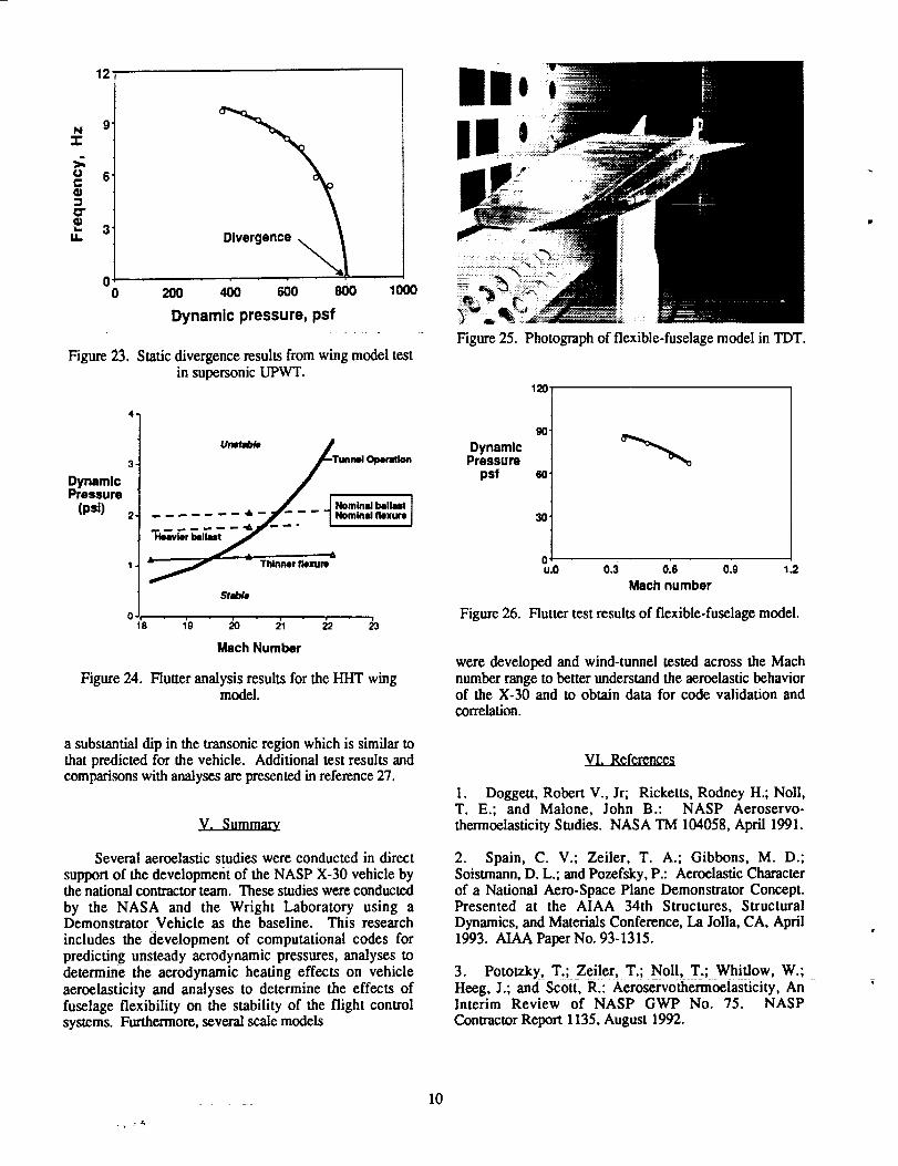
Typically the wing models experience a staticdivergence instability which is influenced by theflexibilities of the pitch actuator and the wing structureforward of the pitch axis. Some results of the supersonic
test 25 in the UPWT are shown figure 23. Subcritical
response data show that the wing pitch frequency decreasesas the dynamic pressure is increased. At the divergencecondition, this frequency is zero.
In addition to static divergence data, it is desirable toacquire flutter data for these all-moveable wings. For the
hypersonic wing test, a mass will be added to the trailing
edge of the model. Analytical pretest flutter predictions 26
for this model are shown in figure 24. The results showthat the addition of mass and the reduction of pivotstiffness both have adverse effects on the flutter stability.
Vehicle flutter
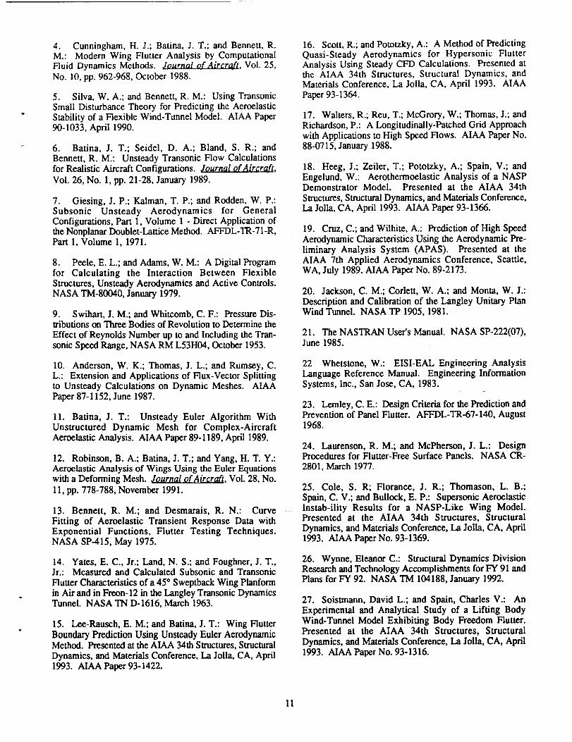
To investigate the transonic aeroelastic behavior ofthe complete vehicle, a full-span model of theDemonstrator Vehicle was developed for testing in the
TDT. The model is pictured in figure 25. The fuselage isapproximately 15 feet in length and is attached to apedestal support system which allows both pitching andplunging motions. The model has all-moveable wings (6-foot span) and twin vertical fins. The dynamiccharacteristics of the baseline model are similar to thoseof
the Demonstrator Vehicle. Model parameters which were
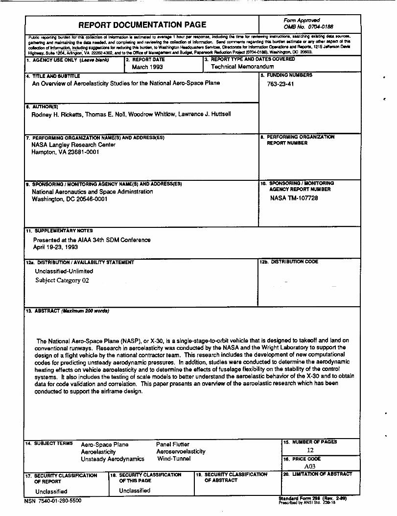
varied during the tests include wing pitch actuator stiffness,wing pitch axis location and fuselage shape. Some resultsfrom the tests 27 are shown in figure 26. The instability
shown here is a coupling of the wing pitch mode andfuselage bending mode. The boundary shows
!t
(a) Transonic model for TDT.
(b) Supersonic model for UPWT.
(c) Hypersonic model HI-rr.
Figure 22. All-moveable wing aeroelastic models.
ORIGINAL PAGE
8L,ACK AND WHITE PHOTOORAPt...I
12'
N 9'
-r
r. 6.
o-"¢ 3"u. Divergence
0 200 400 600 800 1000
Dynamic pressure, psf
Figure 23. Static divergence results from wing model testin supersonic UPWT.
4*
DynamicPressure
(psi)
Heavier kll_
O, ,18 1'9
Thinner flexure
Smb_
Mach Number
Figure 24. Flutter analysis results for the HHT wingmodel.
a substantial dip in the transonic region which is similar tothat predicted for the vehicle. Additional test results andcomparisons with analyses are presented in reference 27.
Several aeroelastic studies were conducted in direct
support of the developmerit of the NASP X-30 vehicle bythe national contractor team. These studies were conducted
by the NASA and the Wright Laboratory using aDemonstrator Vehicle as the baseline. This research
includes the development of computational codes forpredicting unsteady aerodynamic pressures, analyses todetermin_e the aerodynamic heating effects on vehicle
aeroelasticity and analyses to determine the effects offuselage flexibility on the stability of the flight controlsystems. Furthermore, several scale models
!
Figure 25. Photograph of flexible-fuselage model in TDT.
DynamicPressure
psf
12o.
gO"
60"
30
ou.o 0.3 0.6 o.9 1.2
Mach number
Figure 26. Flutter test results of flexible-fuselage model.
were developed and wind-tunnel tested across the Machnumber range to better understand the aeroelastic behaviorof the X-30 and to obtain data for code validation andcorrelation.
VI. References
1. Doggett, Robert V., Jr; Ricketts, Rodney H.; Noll,T. E.; and Malone, John B.: NASP Aeroservo-thermoelasticity Studies. NASA TM 104058, April 1991.
2. Spain, C. V.; Zeiler, T. A.; Gibbons, M. D.;Soistmann, D. L.; and Pozefsky, P.: Aeroelastic Characterof a National Aero-Space Plane Demonstrator Concept.Presented at the AIAA 34th Structures, Structural
Dynamics, and Materials Conference, La Jolla, CA, April1993. AIAA Paper No. 93-1315.
3. Pototzky, T.; Zeile!:_ T._; _N01!,__Tr; Whitlow, W.;Heeg, J.; and Scott, R.: Aeroservothermoelasticity, An _Interim Review of NASP GWP No. 75. NASP
Contractor Report 1135, August 1992.
10
4. Cunningham,H. J.;Batina,J.T.; andBennett,R.M.: ModernWingFlutterAnalysis by ComputationalFluid Dynamics Methods. Journal o.fAircrqft, Vol. 25,
No. 10, pp. 962-968, October 1988.
5. Silva, W. A.; and Bennett, R. M.: Using Transonic
Small Disturbance Theory for Predicting the AeroelasticStability of a Flexible Wind-Tunnel Model. AIAA Paper90-1033, April 1990.
6. Batina, J. T.; Seidel, D. A.; Bland, S. R.; and
Bennett, R. M.: Unsteady Transonic Flow Calculationsfor Realistic Aircraft Configurations. Journal of Aircraft,
Vol. 26, No. 1, pp. 21-28, January 1989.
7. Giesing, J. P.; Kalman, T. P.; and Rodden, W. P.:Subsonic Unsteady Aerodynamics for GeneralConfigurations, Part 1, Volume 1 - Direct Application ofthe Nonplanar Doublet-Lattice Method. _L-TR-7 l-R,Part 1, Volume 1, 1971.
8. Peele, E. L.; and Adams, W. M.: A Digital Programfor Calculating the Interaction Between FlexibleStructures, Unsteady Aerodynamics and Active Controls.NASA TM-80040, January 1979.
9. Swihart, J. M.; and Whitcomb, C. F.: Pressure Dis-tributions on Three Bodies of Revolution to Determine the
Effect of Reynolds Number up to and Including the Tran-sonic Speed Range, NASA RM L53H04, October 1953.
10. Anderson, W. K.; Thomas, J. L.; and Rumsey, C.L.: Extension and Applications of Flux-Vector Splittingto Unsteady Calculations on Dynamic Meshes. AIAAPaper 87-1152, June 1987.
11. Batina, J. T.: Unsteady Euler Algorithm WithUnstructured Dynamic Mesh for Complex-AircraftAeroelastic Analysis. /dAD, Paper 89-1189, April 1989.
12. Robinson, B. A.; Batina, J. T.; and Yang, H. T. Y.:Aeroelastic Analysis of Wings Using the Euler Equationswith a Deforming Mesh. Journal of Aircraft, Vol. 28, No.
11, pp. 778-788, November 1991.
13. Bennett, R. M.; and Desmarais, R.N.: Curve
Fitting of Aeroelastic Transient Response Data withExponential Functions, Flutter Testing Techniques.NASA SP-415, May 1975.
14. Yates, E. C., Jr.; Land, N. S.; and Foughner, J. T.,Jr.: Measured and Calculated Subsonic and Transonic
Flutter Characteristics of a 45 ° Sweptback Wing Planformin Air and in Freon-12 in the Langley Transonic DynamicsTunnel. NASA TN D-1616, March 1963.
15. Lee-Rausch, E. M.; and Batina, J. T.: Wing Flutter
Boundary Prediction Using Unsteady Euler AerodynamicMethod. Presented at the AIAA 34th Structures, Structural
Dynamics, and Materials Conference, La Jolla, CA, April1993. AIAA Paper 93-1422.
16. Scott, R.; and Pototzky, A.: A Method of PredictingQuasi-Steady Aerodynamics for Hypersonic FlutterAnalysis Using Steady CFD Calculations. Presented atthe AIAA 34th Structures, Structural Dynamics, andMaterials Conference, La Jolla, CA, April 1993. AIAA
Paper 93-1364.
17. Waiters, R.; Reu, T.; McGrory, W.; Thomas, J.; andRichardson, P.: A Longitudinally-Patched Grid Approachwith Applications to High Speed Flows. AIAA Paper No.88-0715, January 1988.
18. Heeg, J.; Zeiler, T.; Pototzky, A.; Spain, V.; andEngelund, W.: Aerothermoelastic Analysis of a NASPDemonstrator Model. Presented at the AIAA 34th
Structures, Structural Dynamics, and Materials Conference,La Jolla, CA, April 1993. AIAA Paper 93-1366.
19. Cruz, C.; and Wilhite, A.: Prediction of High Speed
Aerodynamic Characteristics Using the Aerodynamic Pre-liminary Analysis System (APAS). Presented at theAIAA 7th Applied Aerodynamics Conference, Seattle,WA, July 1989. AIAA Paper No. 89-2173.
20. Jackson, C. M.; Corlett, W. A.; and Monta, W. J.:Description and Calibration of the Langley Unitary PlanWind Tunnel. NASA TP 1905, 1981.
21. The NASTRAN User's Manual. NASA SP-222(07),June 1985.
22 Whetstone, W.: EISI-EAL Engineering AnalysisLanguage Reference Manual. Engineering Information
Systems, Inc., San Jose, CA, 1983.
23. Lemley, C. E.: Design Criteria for the Prediction andPrevention of Panel Flutter. AFFDL-TR-67-140, August1968.
24. Laurenson, R. M.; and McPherson, J. L.: DesignProcedures for Flutter-Free Surface Panels. NASA CR-
2801, March 1977.
25. Cole, S. R; Florance, J. R.; Thomason, L. B.;Spain, C. V.; and Bullock, E. P.: Supersonic Aeroelastic
............... Results for a NASP-Like Wing Model.Presented at the AIAA 34th Structures, Structural
Dynamics, and Materials Conference, La Jolla, CA, April1993. AIAA Paper No. 93-1369.
26. Wynne, Eleanor C.: Structural Dynamics DivisionResearch and Technology Accomplishments for FY 91 andPlans for FY 92. NASA TM 104188, January 1992.
27. Soistmann, David L.; and Spain, Charles V.: An
Experimental and Analytical Study of a Lifting BodyWind-Tunnel Model Exhibiting Body Freedom Flutter.Presented at the AIAA 34th Structures, Structural
Dynamics, and Materials Conference, Ida Jolla, CA, April1993. AIAA Paper No. 93-1316.
11
Form ApprovedREPORT DOCUMENTATION PAGE oae No. 0704-0188
Pu_ic reportlngburdenforthiscolk_liono4tnfcm_atlortisuttn'.atedtoa_v'a(le1 hourpermsponN,tndudingthetimeforrevkwvb_ginaructionl,=4torchingexbtt_ _ sour(_m,gathering_ maintainingthedataneeded,andcomplelJngandreviewingtheO0_K:ti¢_O(information.Send_ regardb2 thisburdenestimateor anyoihewa_ el thiscoledlonofInforrna_, includingSUggNtlOn=formdu(:t_thisburden,toWashingtonHeadquatlen=San,,t:xm.D_ector"41efor Iflforma_onOper=_lo¢1andFlepor_.1215Jefftq;onDavisHlght_y.Sule t204./vllngmn.VA 22202-43¢LandtotheOffio_ofManagementandBudget.Pm_m,orkRKlu=lonPn_ (0704-OtM),W=ahlngmn,DC 20503.
1. AGENCY USE ONLY (Leave b_nk) 2. REPORTDATE 3. REPORT TYPE AND DATES COVEREDMarch 1993 Technical Memorandum
4. TITLE AND SUBTITLE 6. FUNDING NUMBERS
An Overview of Aeroelasticity Studies for the National Aero-Space Plane 763-23-41
e. Au'rHO_B)
Rodney H. Ricketts, Thomas E. Nell, Woodrow Whitlow, Lawrence J. Huttsell
!7. PERFORMING ORGANIZATk_N NAME(B)AND ADDRESS(E5)
NASA Langley Reseamh Center
Hampton, VA 23681-0001
9. SPONSORING I MONITORING AGENCY NAME(S) AND ADDRESS(EB)
National Aeronautics and Space Adminstration
Washington, DC 20546-0001
8. PERFORMING ORGANIZATIONREPORT NUMBER
10. SPONSORING/MONITORINGAGENCY REPORT NUMBER
NASA TM- 107728
11. SUPPLEMENTARY NOTES
Presented at the AIAA 34th SDM Conference
April 19-23, 1993
121=.DISTRIBUTION CODE12L DISTRIBUTION / AVAILABILITY STATEMENT
Unclassifiad-Unlim ited
Subject Category 02
13. ABSTRACT (Maximum 200 word#)
The National Acre-Space Plane (NASP), or X-30, is a single-stage-to-orbit vehicle that is designed to takeoff and land on
conventional runways. Research in aeroelasticity was conducted by the NASA and the Wright Laboratory to support the
design of a flight vehicle by the national contractor team. This research includes the development of new computational
codes for predicting unsteady aerodynamic pressures. In addition, studies were conducted to determine the aerodynamic
heating effects on vehicle aemelasticity and to determine the effects of fuselage flexibility on the stability of the control
systems. It also includes the testing of scale models to better understand the aeroelastic behavior of the X-30 and to obtain
data for code validation and correlation. This paper presents an overview of the aemelastic research which has been
conducted to support the airframe design.
14. SUBJECT TERMS Acre-Space Plane
Aeroelasticity
Unsteady Aerodynamics
17. SECURITY CLASSIFICATIONOF REPORT
Unclassified
Panel Flutter
AemservoelasticityWind-Tunnel
lS. SECURITY CLASSIFICATIONOF THIS PAGE
Unclassified
19. SECURITY CLASSIFICATIONOF ABSTRACT
15. NUMBER OFPAGES
12
16. PRICE COOE
A03
20. uMrrATION OF ABS_rRACT
NSN 7540-01-280-5500 Standard Form 298ProscribedbyANSIStd._0-1"o24,1)