for help call 1.800.241
TRANSCRIPT

QUESTIONS? Ask the experts at POSMicro.com.
1.800.241.6264 Live Chat Now [email protected]
Monday - Friday 6 AM to 5 PM Pacific Time
BULk DISCOUNTS
FREE SHIPPING*
SE HaBLa ESpañOL
*Free ground shipping to the continental USa on orders over $100.
For Help Call 1.800.241.6264
Avery-Berkel UserManualMore information available at POSMicro.com

User’s Manual
Model6700Family
Model 6720
Model 6702
Model 6710
Point-of-SaleInterface Scales

Model 6700 Family User’s Manual2
Risk of electrical shock. Do not remove cover. No user serviceableparts inside. Refer servicing to qualified service personnel.
Weigh-Tronix reserves the right to changespecifications at any time.
CAUTION
03/12/02 6700_U.P65 PN 7424-14787E e1 Printed in USA
Model 6700 Family User’s Manual 3
Specifications ...................................................... 4
Initial Setup ......................................................... 7
Operation ............................................................ 8
Menu Structure .................................................. 11
Diagnostics Mode .............................................. 13
Configuration Mode ........................................... 17
Calibration Mode ............................................... 19
Review/Test Scale Settings ............................... 21
Communication ................................................. 22
Error Codes ....................................................... 24
Troubleshooting................................................. 25
Spare Parts Listing ............................................ 27
Table of Contents

Model 6700 Family User’s Manual4
SpecificationsDescription
Capacity/Resolution
Agency Certificates of Conformance
The NCI 6700 models are digital electronic benchscales specifically designed for point-of-saleapplications and are “Legal-for-Trade.” Thescales are easily interfaced with a cash register,computer or other POS terminal.
Important! Weights and Measures normallyrequires inspection of scale before scale isplaced into operation.
Model Capacity (lb) Capacity (kg)6702-7 15 x .005 7 x .0026702-15 30 x .01 15 x .0056710-7 15 x .005 7 x .0026710-15 30 x .01 15 x .0056720-7 15 x .005 7 x .0026720-15 30 x .01 15 x .0056720-30 60 x .02 30 x .016720-60 120 x .05 60 x .024740-15 30 x .01 15 x .005
Model 6702/6710/6720US and Canada Approved Legal for TradeUSA: NTEP COC# 95-070Canada: MOI# AM-5076
Model 4740US and Canada Approved Legal for TradeUSA: NTEP COC# 92-151Canada: MOI# AM-4778

Model 6700 Family User’s Manual 5
Model 6702: 10.4 x 6.4 x 2.5Model 6710: 10.4 x 10.4 x 2.5Model 6720: 14.1 x 12.6 x 4.1Model 4740: 14.0 x 10.0
UL/CSA approved power supply with 6’ line cord
6702/6710: Wallmount6720: In-line mounted below scale
Input: 120 VAC +10%-15%, Standard 3 wirew/ground
Output: 15 VDC @.3 Amps DC
50/60 Hz selectable
0.1 amp maximum
42ºF – 104ºF (5ºC – 40ºC)10% to 95% RH (non-condensing)
Models 6702/6710: Aluminum Base and LoadBridge with stainless steel weigh platter.Overload protection: Adjustable center and sidestops.
Model 6720: Die cast aluminum base with astainless steel weigh platter.Overload protection: Adjustable center stop, fixedcorner stops.
½" high, six-digit LCD.Key panel with ZERO and TEST keys.Remote display with 7 ft. cable. Standard onModels 6702 and 6710, optional on 6720.
Using the leveling bubble as a guide, adjust thefour adjustable feet to level the scale.
Initial automatic zero setting is ±10% of maxi-mum capacity—active at power up. Manual zerosetting range is ±2% of maximum capacity—active using the ZERO key.
Dimensions
Power Supply
Frequency
Power Requirements
Operating Temperature
Construction
Display
Scale Leveling
Zero Window

Model 6700 Family User’s Manual6
Under Capacity Limits
Over Capacity Limits
Sealing
Internal Counts
Dynamic Response
Communications
Under capacity indication will be given withdashes appearing on the bottom line of thedisplay whenever the display is below the initialzero value.
Over capacity indication will be given with dashesappearing in the upper line of the display when-ever the weighed item exceeds 9 divisions overthe rated capacity of the unit. The scale will usethe initial zero value for reference for overcapacity determination.
Access to the calibration switch can be securedwith a lead wire or pressure sensitive securityseal. The remote or primary indicators have nometrological features that require the use of asecurity seal.
The scale has 100,000 internal counts.
The time interval when weight is applied to thescale until a stable weight is displayed:
0–1000d,1.5 seconds1000d+, 2.0 seconds
maximum mean average
Factory default settings: 9600 baud, 7 data bits,even parity, 1 stop bit.
Specific cable requirements are determined byparticular POS terminal. A standard 9-pin passthrough RS-232 interface cable is necessary formost PC interfaces. Not a null modem.
RS-232 bidirectional, configurable 1200 to 19.2Kbaud. Transmits weight and scale status when-ever ASCII “W” <CR> is sent by the POS termi-nal. Standard ECR protocol is OPOS compatible.For Protocol details contact factory.

Model 6700 Family User’s Manual 7
Initial Setup1. Remove contents of the shipping container.
2. Inspect the scale for evidence of shippingdamage. Immediately report any damage tothe shipper.
1. Mount the scale on a stable, level surfacethat is free from air currents and vibration. Besure the scale platter does not touch anyadjacent surfaces.
2. To install the scale surface flush with acountertop, use the dimensions on thefollowing page to guide construction.
Scale Dimensions Min. Cut-Out DimensionsD 10.4 in. (26.4 cm) 11.1 in. (28.2 cm)W 6.4 in. (16.3 cm) 7.1 in. (18.0 cm)H 2.5 in. (6.35 cm)**Adjustable to 3.0 in. (7.6 cm)
Scale Dimensions Min. Cut-Out DimensionsD 10.4 in. (26.4 cm) 11.1 in. (28.2 cm)W 10.4 in. (26.4 cm) 11.1 in. (28.2 cm)H 2.5 in. (6.35 cm)**Adjustable to 3.0 in. (7.6 cm)
Scale Dimensions Min. Cut-Out DimensionsD 12.6 in. (32.0 cm) 13.25 in. (33.7 cm)W 14.1 in. (35.8 cm) 14.75 in. (37.5 cm)H 4.1 in. (10.4 cm)**Adjustable to 4.6 in. (11.7 cm)
Unpacking the Scale
Installing the Scale
Model 6702
Model 6710
Model 6720

Model 6700 Family User’s Manual8
OperationPower Up Test
Sequence
If RAM or ROM erroris reported, you mustpress the TEST key toacknowledge thecondition. See “ErrorCodes” section.
3. Loosen the collets or jam nuts on the levelingfeet. Level the scale by using the level bubbleunder the scale platter as a guide. Be sure allfour feet are in firm contact with the counter,then tighten all collets and jam nuts.
4. Make sure all power cords, remote displaycables, etc., are not touching the live weigh-ing surface.
5. Plug the unit into an appropriate voltageoutlet that is properly grounded.
6. The 6720 scale can support more than onedisplay; however, only one keypad is oper-able. Switch 3 selects internal or externaldisplay keypad operation.
Switch 3 SettingsClosed= internal display keys operationalOpen = external display keys operational
The normal setting for the 6720 with theinternal display is Switch 3=Closed. On 6720w/remote only or 6710 and 6702 scales,Switch 3=Open.
When the scale is first powered up, it will performa test sequence. During this sequence, thedisplay will show the following:
• The model number and the softwareversion/revision level.
• A numeric counting test for all segments ofthe display. During this test, a test ofRandom Access Memory (RAM) and a testof Read Only Memory (ROM) is performed.
If everything is OK, the display will show zeroweight and the scale is ready for use.
Model 6700 Family User’s Manual 9
1. With the scale powered on, make sure thescale platter is empty and the display is atzero. If it is not, press the ZERO key…
0.00 is displayed.
2. Place an item to be weighed on the scaleplatter…
The scale will display the gross weight.
3. Remove the item from the scale platter.
ZERO Key – The ZERO key will zero the scale ifweight is stable, and acts as the NO or SCROLLkey in the Menu mode.
TEST Key – The TEST key can be used toperform the initial power-up test sequence, recalldiagnostic routines, or to view the scale configu-ration information. This key also acts as YES orACCEPT in the Menu mode.
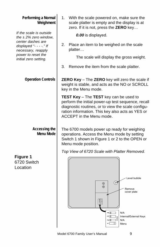
The 6700 models power up ready for weighingoperations. Access the Menu mode by settingSwitch 1 shown in Figure 1 or 2 to the OPEN orMenu mode position.
Top View of 6720 Scale with Platter Removed.
Performing a NormalWeighment
If the scale is outsidethe ± 2% zero window,center dashes aredisplayed “- - - -.” Ifnecessary, reapplypower to reset theinitial zero setting.
Operation Controls
Accessing theMenu Mode
Figure 16720 SwitchLocation

Model 6700 Family User’s Manual10
There are three modes available to you withSwitch 1 in the Menu mode or OPEN position.They are as follows:
DIAG (Diagnostic Mode) – To test areas ofthe scale’s function
CAL (Calibration Mode) – To calibrate thescale
CONF (Configuration Mode) – To configurethe scale for your application
The structure for these menus is shown in Figure3. Specific information about each mode followedby step-by-step instructions for accessing themare described in the following pages.
Figure 2Bottom view
Menu Mode
Bottom View of 6702 or 6710 Scale

Model 6700 Family User’s Manual 11
Figure 3Menu Structure

Model 6700 Family User’s Manual12
AlternateCalibration Points
Table 1AlternativeCalibration Points
Baud Rate andParity Options
Table 2Baud Rate andParity Options
The NCI 6700 bench scales allow calibrationusing less than full capacity weights. See Table 1for alternative weights that can be used tocalibrate your scale for its designated capacity.
AlternativeCapacity Calibration Weights9.995 lb 10 lb15 x .005 lb 10, 15 lb7 x .002 kg 7 kg9.995 kg 10 kg30 x .01 lb 10, 20, 30 lb15 x .005 kg 10, 15 kg60 x .02 lb 10, 30, 60 lb30 x .01 kg 10, 20, 30 kg99 x .05 lb 10, 50, 100 lb120 x .05 lb 10, 50, 100 lb60 x .02 kg 10, 30, 60 kg
Display Baud Parity12 E 1200 Even24 E 2400 Even48 E 4800 Even96 E* 9600 Even19.2 E 19.2K Even12 o 1200 Odd24 o 2400 Odd48 o 4800 Odd96 o 9600 Odd19.2 o 19.2K Odd12 n 1200 None24 n 2400 None48 n 4800 None96 n 9600 None19.2 n 19.2K None
*Default Factory Settings

Model 6700 Family User’s Manual 13
The Diagnostic (DIAG) mode menu allowstesting of specific areas of the scale’s functionand viewing current configuration settings. Thisincludes the following:
DISPLAY (DISP) – Shows the version andrevision of the software, followed by a displaysegment test.
RAM (RA) – Performs a nondestructive test ofRAM in the processor.
ROM (RO) – Performs a checksum of all loca-tions of ROM in the processor.
INPUT/OUTPUT (I/O) – Data is output by thescale and through the use of a loopback connec-tor. The data is immediately read back into thereceive channel and verified against what wassent. Requires a jumper (short) between transmitand receive data lines.
DIVISION TEST, w/AZT (DIV-A) – Weight datais normalized to 100,000 counts of displayedresolution. AZT (Auto Zero Tracking) is enabled.
DIVISION TEST, w/o AZT (DIV-N) – Weight datais normalized to 100,000 counts of displayedresolution. AZT is disabled.
Viewable configuration settings include:
LN FR Line frequencyFILT Filter settingPROT Serial protocolBAUD Baud rateCAP Scale capacityUNITS Unit of measure
Diagnostics ModeDiagnostic (DIAG) Mode
Tip: Easy access tothe diagnostic mode isavailable directly fromthe front panel withoutopening the scale toaccess the Menumode switches. SeeSetup Review/Testsection.

Model 6700 Family User’s Manual14
If you encounter anyfailure in these tests,contact your localWeigh-Tronix dealer.
Press the ZERO key toscroll through lists ofselections.
Press the TEST key tomake a selection.
To skip a test, pressthe ZERO key to scrollto the next test.
Follow these steps to access the tests in theDIAG menu.
1. From normal weighing mode, move Switch 1to the Menu mode or OPEN position. (SeeFigure 1 or 2).
DIAG is displayed.
2. Press the TEST key. . .
DISP is displayed. This stands fordisplay.
3. Press the TEST key to perform the displaytest described earlier…
Display test is performed and the displayshows DISP after the test is completed.
4. Press the ZERO key…
RA is displayed. This stands for the RAMtest.
5. Press the TEST key to perform the RAMtest…
PASS or FAIL is displayed briefly; thenRA.
6. Press the ZERO key…
RO is displayed. This stands for theROM test.
7. Press the TEST key to perform the ROMtest . . .
PASS or FAIL is displayed briefly; thenRO.
8. Press the ZERO key…
I/O is displayed. This stands for theINPUT/OUTPUT test.

Model 6700 Family User’s Manual 15
9. With a loopback connector in place, pressthe TEST key to perform the I/O test…
PASS or FAIL is displayed briefly, thenI/O. This test is only valid on 9-pin or15-pin models configured as “RS” units.
10. Press the ZERO key . . .
DIV-A is displayed. This stands for thehigh resolution DIVISION TEST W/AZTenabled. See note at left.
11. Press the TEST key to perform this test…
The display shows the weight on thescale at a resolution of 100,000 counts.
12. Press the TEST key to stop the test…
DIV-A is displayed.
13. Press the ZERO key…
DIV-N is displayed. This stands for thehigh resolution DIVISION TEST w/o AZTenabled.
14. Press the TEST key to perform this test…
The display shows the weight on thescale at a resolution of 100,000 counts.
15. Press the TEST key to stop the test…
DIV-N is displayed.
16. Press the ZERO key…
LN FR is displayed. This stands for linefrequency.
17. Press the TEST key...
The current line frequency (50 or 60) isdisplayed.
DIAG will flash every15 seconds during thehigh resolution test asa reminder that youare doing a test andnot seeing normalweight readings.
The remainingselections are forviewing currentsettings only. You canscroll through themenu to verify thesettings, but to makechanges, you mustenter configuration orcalibration.
9-Pin RS-232 models:
On 15-Pin “RS” units,jumper from Pin 1 to 2.

Model 6700 Family User’s Manual16
18. Press the ZERO key…
FILT is displayed. This stands for filter-ing.
19. Press the TEST key…
The current filter setting, FAST or SLO,is displayed.
18. Press the ZERO key…
PROT is displayed. This stands forprotocol.
19. Press the TEST key…
The current serial protocol selection isdisplayed.
20. Press the ZERO key…
BAUD is displayed. This stands for baudrate.
21. Press the TEST key…
The current baud rate and parity selec-tion is displayed.
22. Press the ZERO key…
CAP is displayed. This stands for capac-ity.
23. Press the TEST key…
The current capacity/resolution selectionis displayed.
24. Press the ZERO key…
UNITS is displayed. This stands for unit-of-measure.
25. Press the TEST key.
The current unit-of-measure LBS (forpounds) or 1000G (for kilograms), isdisplayed.

Model 6700 Family User’s Manual 17
The Configuration (CONF) Mode menu allowsscale configuration for your specific applicationneeds. The items you can configure are asfollows:
FILTERING (FILT) – Choose between FAST andSLO filtering. SLO should be chosen in areassusceptible to vibration. Choose FAST filteringfor more stable conditions.
Baud (BAUD) – Choose a baud and parity fromTable 2.
Protocol (PROT) – Select the RS-232 communi-cation protocol.
NCI – NCI standardECR – Cash register compatible8213 – 8213 compatible (Sharp)2250 – 2250 compatible (Swintec)34-F – 34-MF compatible (Sweda-Mexico)ATT – AT&T compatibleo4000 – Olympia Cash Register compatible
Access the Menu mode as shown in Figure 3.
1. From the DIAG display, press the ZERO keyuntil CONF is displayed, or from the normalweighing mode, move Switch 1 to the Menumode or the OPEN position; then press theZERO key until CONF is displayed.
Configuration Mode
26. When you are finished, press the ZERO key,until DONE is displayed, then press theTEST key to return to the top menu level…
DIAG is displayed. Or close Switch 1 toreturn to normal weighing mode.

Model 6700 Family User’s Manual18
2. Press the TEST key…
FILT is displayed.
3. Press the TEST key…
The current setting, FAST or SLO,is displayed.
4. Use the ZERO key to toggle between the twochoices. Press the TEST key when thechoice you want is displayed. The choice isaccepted and the display shows the FILTitem.
5. Press the ZERO key…
BAUD is displayed.
6. Press the TEST key…
The current baud and parity choice isdisplayed.
7. Use the ZERO key to scroll the choicesfound in Table 2. When the choice you wantis displayed, press the TEST key. The choiceis accepted, and the display shows the BAUDitem.
8. Press the ZERO key until…
PROT is displayed.
9. Press the TEST key…
The current RS-232 communicationprotocol is displayed.
10. Press the ZERO key to scroll through thechoices. When the choice you want isdisplayed, press the TEST key. The choice isaccepted and the display shows the PROTitem.

Model 6700 Family User’s Manual 19
The Calibration (CAL) Mode menu lets youcalibrate your scale. The items in the calibrationmenu are as follows:
POUNDS/KILOGRAMS (LBS or 1000 Gr) –Selects the unit of measure of your calibrationtest weights (lb or kg).
CAPACITY (9.995, 15.005, 30.01, 60.02 etc.) –Select the capacity of the scale.
Follow these steps to calibrate the scale. Refer toFigure 3.
1. From the DIAG display, press the ZERO keyuntil CAL is displayed, or from the normalweighing mode, move Switch 1 to the Menumode or OPEN position. Press the ZEROkey until CAL is displayed.
2. Press the TEST key…
50 H or 60 H is displayed. This is the ACline frequency.
3. Press the ZERO key to toggle between thechoices. When the choice you want isdisplayed, press the TEST key…
That choice is accepted and LB or KILOis displayed.
4. Press the ZERO key to toggle between thechoices. When the choice you want isdisplayed, press the TEST key…
The scale capacity is displayed.
(Example: 9.995)
If a different capacity selection is desired,press the ZERO key to scroll through thechoices.
Calibration Mode
Step-by-StepInstructions
for CAL Mode
Model 6700 Family User’s Manual20
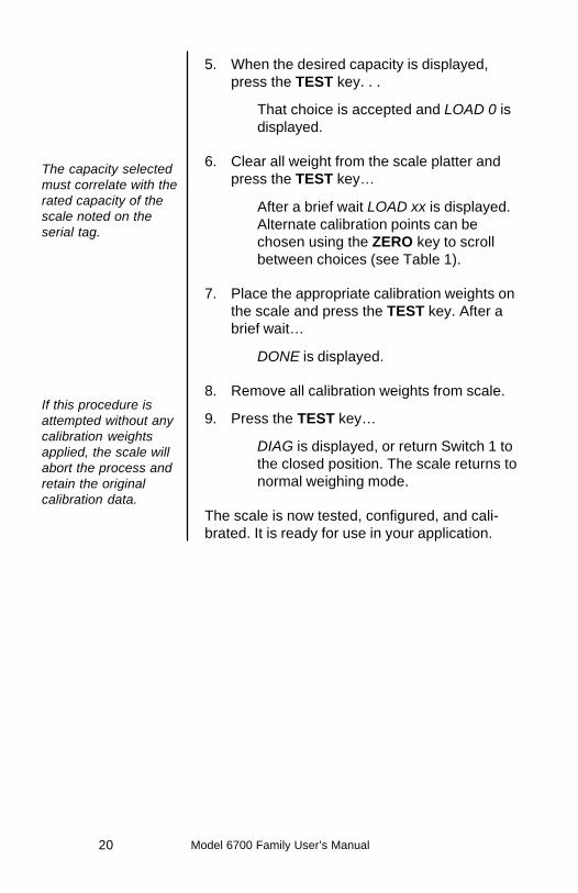
5. When the desired capacity is displayed,press the TEST key. . .
That choice is accepted and LOAD 0 isdisplayed.
6. Clear all weight from the scale platter andpress the TEST key…
After a brief wait LOAD xx is displayed.Alternate calibration points can bechosen using the ZERO key to scrollbetween choices (see Table 1).
7. Place the appropriate calibration weights onthe scale and press the TEST key. After abrief wait…
DONE is displayed.
8. Remove all calibration weights from scale.
9. Press the TEST key…
DIAG is displayed, or return Switch 1 tothe closed position. The scale returns tonormal weighing mode.
The scale is now tested, configured, and cali-brated. It is ready for use in your application.
The capacity selectedmust correlate with therated capacity of thescale noted on theserial tag.
If this procedure isattempted without anycalibration weightsapplied, the scale willabort the process andretain the originalcalibration data.

Model 6700 Family User’s Manual 21
The TEST key located on the front panel lets youperform some basic system diagnostics, as wellas review the current system settings withouthaving to access switches inside the scale.
Review/Test Scale Settings
IMPORTANT: If youpress and release theTEST key, the displaywill show the scalesmodel number,version-revision, andperforms a displaytest.To review the currentsystem settings, pressand hold the TESTuntil the display showsdashes“_ _ _ _.” Release theTEST key and thedisplay will promptDISP andthe scale is now in theReview/Test Mode.
Press the ZERO key tomove to the next itemin the menu
Press the TEST key toselect the displayeditem to run or view.
When finished running tests or viewing thesettings, press the ZERO key until DONE isdisplayed. Then press the TEST key to return tonormal (i.e., weighing) mode of operation.
IMPORTANT: Internalrocker switches will beignored until you exitthis special mode orpower reset the scale.

Model 6700 Family User’s Manual22
Communication
CommunicationsEnabled
Serial DataTransmission
Modem control lineswill not be supportedfor RS-232
4-Bit ParallelECR Interface
The 6700 is capable of interfacing with an EIAStandard RS-232, full duplex, asynchronous,smart device, or 4-bit parallel interface foroutput of weight data to an ECR device. The6700 15 pin style is normally configured as a 4-bit Parallel standard from the factory. The 67009-pin style is capable of RS-232 communicationonly.
Serial commands will be responded to onlywhen the scale is in the ‘normal’ operatingmode and Switch 1 on the main board is in theCLOSED position.
Baud Rates:1200, 2400, 4800, 9600, or 19.2K
Word Length: 10 Bits1 Start, 7 Data, 1 Parity, 1 StopParity: Even, Odd, or None
The scale is DTE.
The 15 pin version of the 6700 is normallyshipped configured to function as a 4-bitparallel interface device.
Follow these steps to configure the scale toserial RS-232 interface operation.
1. Locate the dip shunt jumper at JMP2 on themain PC board.
2. Place the jumper so the shorting pins arelocated away from the DE-15 connector atend of the PC board. See Figure 4 below.

Model 6700 Family User’s Manual 23
The scale end of the interface cable plug is a DA15 pin socket. The other end is as required byyour application.
Below is a pin and signal list for the DA 15 pininterface cable.
Pin RS-232 4-Bit Parallel
1 RXD Data 12 TXD Data 23 Sig Gnd Sig Gnd4 Data 4 Data 45 Data 8 Data 86 DSR Over Capacity7 DTR NC8 BHZ BHZ9 /In Motion /In Motion10 Sig Gnd Sig Gnd11 /Enable /Enable12 Sig Gnd Sig Gnd13 Clock Clock14 Sig Gnd Sig Gnd15 Sig Gnd Sig Gnd
Figure 4Partial View of the4-Bit ParallelMain PC Board

Model 6700 Family User’s Manual24
Error Codes
The 9-pin version of the 6700 has DE typefemale connector accessible at the rear of theunit. The functional pinout of this connector iscompatible with a standard PC with a pass-through cable.
DE-9 Female Scale DE-9 Male HostPin Name Direction Pin Name Direction1. JMP 1 - 1. DCD IN2. TXD OUT 2. RXD IN3. RXD IN 3. TXD OUT4. JMP 1 - 4. DTR OUT5. SG - 5. GRD -6. JMP 1 - 6. DSR IN7. JMP 2 - 7. RTS OUT8. JMP 2 - 8. CTS IN9. NC - 9. RI IN
Any system errors detected by the scale will bedisplayed as the letter E followed by a two-digiterror code. Press the TEST key to continueoperation. If a calibration error occurs, the onlyway to clear it is by recalibrating the scale.
The error codes are broken down into twohexadecimal numbers, with each bit defining asingle error condition. The error codes aredefined as follows:
RS-232 Interface
* Jmp1 and Jmp2 pinsare connectedinternally on the scalePCB connector.

Model 6700 Family User’s Manual 25
Perform the following steps in the order pre-sented until the described problem is corrected.
No Power (Display is Blank)1. Check that the primary side of the cord is
plugged into the AC outlet, and the second-ary side is properly connected to the powerjack on the back of the scale.
2. Replace the power supply.3. Replace the display board.4. Replace the main board.
Missing or extra segments on display1. Replace the display board.2. Replace the main board.
Scale will not return to zero, or incorrectweight is displayed1. Press the ZERO key.2. Check for interference of weighing platform.3. Power down, remove all items from the
platter, and then power up the scale.4. Recalibrate the scale.5. Replace the load cell.6. Replace the main board.
Troubleshooting
If an E-02 ROM erroror E-04 RAM erroroccurs, power thescale off and thenback on. If it occursagain contact yourWeigh-Tronix scaleservice provider.
Model 6700 Family User’s Manual26
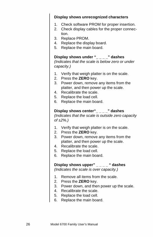
Display shows unrecognized characters
1. Check software PROM for proper insertion.2. Check display cables for the proper connec-
tion.3. Replace PROM.4. Replace the display board.5. Replace the main board.
Display shows under “_ _ _ _” dashes(Indicates that the scale is below zero or undercapacity.)
1. Verify that weigh platter is on the scale.2. Press the ZERO key.3. Power down, remove any items from the
platter, and then power up the scale.4. Recalibrate the scale.5. Replace the load cell.6. Replace the main board.
Display shows center“_ _ _ _” dashes(Indicates that the scale is outside zero capacityof ±2%.)
1. Verify that weigh platter is on the scale.2. Press the ZERO key.3. Power down, remove any items from the
platter, and then power up the scale.4. Recalibrate the scale.5. Replace the load cell.6. Replace the main board.
Display shows upper” _ _ _ _ “ dashes(Indicates the scale is over capacity.)
1. Remove all items from the scale.2. Press the ZERO key.3. Power down, and then power up the scale.4. Recalibrate the scale.5. Replace the load cell.6. Replace the main board.

Model 6700 Family User’s Manual 27
Scale is not transmitting data to the hostdevice
1. Check cable connection at both the rearof the scale and the host device.
2. Check communication setting and baud rateon both scale and software.
3. Perform I/O loopback test.4. Replace the cable.5. Replace the main board.
The ZERO key and the TEST key do notfunction
1. Open display enclosure and verify that thekeypad cable is still installed correctly.
2. Replace the display panel.3. Replace the display PCB.4. Replace the display cable.5. Replace the main PCB.
DESCRIPTION PART NUMBERKeyboard Panel 1163-13205Display PCB 7405-15465RS-232 PCB 7405-14704-24 Bit Parallel PCB 7405-14653-240 Bit Serial PCB 7405-14864-2Power Supply - 6702/6710 1148-15535Power Supply - 6720 1148-15536RS-232 Cable - PC 1140-138426700-7 Kg Loadcell 7154-16323-076700-15 Kg Loadcell 7154-16323-156700-30 Kg Loadcell 7154-16323-306700-60 Kg Loadcell 7154-16323-50Remote Display Kit 7300-16577-01Remote Pole Kit 7200-14837Remote Pole/Displ Kit 7’ 7300-16864-01Remote Pole/Displ Kit 14’ 7300-16864-026702/6710 Fr/Rear Mt. Bkt.7200-148296700 Feet 7075-102566702/6710 Frt Mt. Bkt. 1062-17061
Spare Parts Listing

Model 6700 Family User’s Manual28
Notes

Model 6700 Family User’s Manual 29

Model 6700 Family User’s Manual30

Model 6700 Family User’s Manual 31

1000 Armstrong DriveFairmont, MN 56031Telephone: 507-238-4461Facsimile: 507-238-4195E-Mail: [email protected]