for air monitoring automation and remote control project · pdf fileair monitoring automation...
TRANSCRIPT
SOLICITATION FOR
AIR MONITORING AUTOMATION AND REMOTE CONTROL PROJECT
Submittal: Proposals must be received at the address below on or before
Wednesday, November 2, 2011, 5:30 PM
Proposals received after the date and time stated above will not be accepted.
Submissions must include: Five (5) printed copies and one (1) electronic copy (CD-ROM) of all
submittal documents in Word or PDF format. Address Submissions to: Nathan Trevino, Supervising Air Quality Instrument Technician San Joaquin Valley Unified Air Pollution Control District 1990 East Gettysburg Avenue Fresno, CA 93726-0244 Mark Envelope: “SOLICITATION: Air Monitoring Automation and Remote Control
Project” RFP Issuance Date: September 19, 2011 Contact: Nathan Trevino, (559) 230-6000, [email protected]

Solicitation - Air Monitoring Automation and Remote Control Project
2 | P a g e
TABLE OF CONTENTS
1.0 INTRODUCTION ...................................................................... 7
1.1 Background ............................................................................................ 7
1.2 Key Decision Criteria .............................................................................. 8
1.3 Purchaser Profile .................................................................................... 9
1.3.1 Existing System ............................................................................... 10
1.3.1.1 Monitoring Equipment ............................................................... 10
1.3.1.2 Data Acquisition System (DAS) ................................................ 11
1.3.1.3 Air Quality Data Management System (AQDMS) ..................... 11
1.3.1.4 Remote Control System ............................................................ 11
1.3.1.5 Communication Links ............................................................... 12
1.4 Project Schedule .................................................................................. 13
1.5 Proposal Format ................................................................................... 13
2.0 PERFORMANCE REQUIREMENTS & TECHNICAL SPECIFICATIONS .......................................................................... 15
2.1 Vendor Questionnaire ........................................................................... 15
2.1.1 Vendor Profile ................................................................................. 15
2.1.2 Programming or Integration ............................................................. 15
2.1.3 Other Manufactures......................................................................... 16
2.1.4 Installer ............................................................................................ 16
2.1.5 Maintenance .................................................................................... 16
2.1.6 Support Center ................................................................................ 16
2.1.7 On-site Assistance .......................................................................... 16
2.1.8 Investment Protection ...................................................................... 16
2.1.9 Customer Participation .................................................................... 16
2.1.10 References ...................................................................................... 16
2.1.11 Insurance ........................................................................................ 17
2.2 General System Design ........................................................................ 17
2.2.1 General Requirements & Specification ............................................ 17
2.2.2 Server Architecture and Design ...................................................... 17
2.2.2.1 Server Hardware ....................................................................... 17
2.2.2.2 Network Operating System ....................................................... 17
2.2.2.3 Database Management System................................................ 17
2.2.3 Network Infrastructure ..................................................................... 18
Solicitation - Air Monitoring Automation and Remote Control Project
3 | P a g e
2.2.4 Client Architecture ........................................................................... 18
2.2.5 Communication Services ................................................................. 18
2.2.6 Disaster Recovery ........................................................................... 18
2.3 Data Conversion ................................................................................... 18
2.3.1 General Requirements & Specifications .......................................... 18
2.4 Application Software ............................................................................. 19
2.4.1 Global Requirements ....................................................................... 19
2.4.1.1 User Interface ........................................................................... 19
2.4.1.2 File Structures........................................................................... 19
2.4.2 Automation, Remote Communications and Remote Control Programs ..................................................................................................... 20
2.4.2.1 Polling/Retrieval ........................................................................ 20
2.4.2.2 Polling/Retrieval Compatibility .................................................. 21
2.4.2.3 Remote Control of Data Acquisition System (DAS) .................. 21
2.4.2.4 Power Cycling of Data Acquisition System (DAS) .................... 21
2.4.2.5 Flagging of Raw Data ............................................................... 21
2.4.2.6 Remote Actuation of Calibration Sequences ............................ 21
2.4.2.7 Remote Actuation of Manual Calibrations ................................. 22
2.4.2.8 Remote Real-Time Display and Control of Strip Charts ............ 22
2.4.2.9 Retrieval of Logbook Notes ...................................................... 22
2.4.2.10 Retrieval of Quality Assurance Information ............................... 22
2.4.2.11 Retrieval of Power Failure Logs ................................................ 23
2.4.2.12 Retrieval of Strip Chart Data ..................................................... 23
2.4.2.13 Retrieval of Hourly Averages .................................................... 23
2.4.2.14 Retrieval of Checklist Data ....................................................... 23
2.4.2.15 Retrieval of Calibration Data ..................................................... 23
2.4.2.16 Time Synchronization ............................................................... 23
2.4.2.17 Periodic Maintenance Activities ................................................ 24
2.4.2.17.1 Interaction with Air Monitoring Analyzers and Equipment ... 24
2.4.2.17.2 In-line Sampling Filters ........................................................ 24
2.4.2.17.3 Introduction of Zero Air ........................................................ 24
2.4.2.17.4 Leak and Pressure Checks ................................................. 24
2.4.3 Data Editor Program........................................................................ 24
2.4.3.1 Editing Individual Hourly Values ............................................... 25
2.4.3.1.1 Linear Interpolation ............................................................... 25
Solicitation - Air Monitoring Automation and Remote Control Project
4 | P a g e
2.4.3.1.2 Slope and Intercept ............................................................... 25
2.4.3.1.3 Constant Offsets ................................................................... 25
2.4.3.1.4 Percent Differences .............................................................. 25
2.4.3.1.5 Editing Data Flags ................................................................ 25
2.4.3.2 Printing Data Files .................................................................... 26
2.4.3.2.1 Format of Printed Data.......................................................... 26
2.4.3.2.2 Printout or Display of Results ................................................ 26
2.4.3.3 Note System ............................................................................. 26
2.4.4 Edit Trail Program ........................................................................... 27
2.4.4.1 Summary of All Edits Done to Data File .................................... 27
2.4.4.1.1 Edit Session .......................................................................... 27
2.4.4.1.2 Edit Date and Time ............................................................... 27
2.4.4.1.3 Editor’s Name ....................................................................... 27
2.4.4.1.4 Edit Activity ........................................................................... 27
2.4.4.1.5 Starting and Ending Day and Hour ....................................... 27
2.4.4.1.6 Starting Value ....................................................................... 28
2.4.4.1.7 Ending of Final Edited Value ................................................. 28
2.4.4.1.8 Flags ..................................................................................... 28
2.4.4.1.9 Display of User Editing Notes ............................................... 28
2.4.4.1.10 Restoration to Previously Edited or Unedited State ............ 28
2.4.4.1.11 Printing Edit Trail Summary ................................................ 28
2.4.5 Quality Assurance Program ............................................................ 28
2.4.5.1 Data Screening Program .......................................................... 28
2.4.5.2 Preventative Maintenance Schedule Program .......................... 29
2.4.5.3 Calibration Summary Reports ................................................... 29
2.4.5.3.1 Standard Reports .................................................................. 29
2.4.5.3.2 Calibration Summary Report ................................................. 29
2.4.5.3.3 Theoretical vs. Actual Calibration Data Report ..................... 30
2.4.5.4 Precision Statistics Report ........................................................ 30
2.4.5.4.1 Station Name and Pollutant .................................................. 30
2.4.5.4.2 Number and Date of Precision Calibrations .......................... 30
2.4.5.4.3 Baseline Zero ........................................................................ 30
2.4.5.4.4 Net Data Logger Response After Corrections ....................... 30
2.4.5.4.5 Net Data Logger Response with No Corrections .................. 30
Solicitation - Air Monitoring Automation and Remote Control Project
5 | P a g e
2.4.5.4.6 True Concentration ............................................................... 30
2.4.5.4.7 Net Data Logger Percent Difference ..................................... 31
2.4.5.4.8 Average Percent Difference .................................................. 31
2.4.5.4.9 Standard Deviation ............................................................... 31
2.4.5.4.10 Lower and Upper Probability Limit ...................................... 31
2.4.5.5 X Bar R Control Charts ............................................................. 31
2.4.5.6 Power Failure Summary Reports .............................................. 31
2.4.5.7 Data Statistics Summary Report ............................................... 32
2.4.5.8 Air Quality Values Relative to Standards .................................. 32
2.4.5.9 Data Completeness Report ...................................................... 32
2.4.6 Strip Chart Program ........................................................................ 33
2.4.6.1 User Interface ........................................................................... 33
2.4.6.2 Vertical or Horizontal Display .................................................... 33
2.4.7 Rose Plots ....................................................................................... 33
2.4.8 Frequency Distributions ................................................................... 33
2.4.9 Standard Reports ............................................................................ 33
2.4.10 AIR Quality system (AQS) Generation Program ............................. 34
2.4.11 Precision and Accuracy Reporting System (PARS) Generation Program ....................................................................................................... 34
2.4.12 System Security .............................................................................. 34
2.4.13 Alarm System .................................................................................. 34
2.4.13.1 Alarm Threshold Tables ............................................................ 35
2.4.14 Fixed Asset Tracking Program ........................................................ 35
3.0 DELIVERY AND INSTALLATION ......................................... 35
3.1 Project Management ............................................................................ 35
3.1.1 Project Plan ..................................................................................... 35
3.1.2 Responsibility Matrix/Schedule ....................................................... 35
3.2 Installation Requirements ..................................................................... 35
3.2.1 Responsibility .................................................................................. 35
3.2.2 Initial Work ...................................................................................... 35
3.2.3 Charges ........................................................................................... 36
3.3 Facility Requirements ........................................................................... 36
3.3.1 Power .............................................................................................. 36
3.3.2 Heat, Temperature, and Humidity ................................................... 36
Solicitation - Air Monitoring Automation and Remote Control Project
6 | P a g e
3.3.3 Floor Loading .................................................................................. 36
3.4 Cable Requirements ............................................................................. 36
3.5 Training ................................................................................................. 36
3.5.1 Training Requirements .................................................................... 36
3.5.2 Training Plan ................................................................................... 36
3.5.3 Training Description ........................................................................ 37
3.5.4 Materials .......................................................................................... 37
3.6 System Administration .......................................................................... 37
4.0 VENDOR SERVICE ............................................................... 37
4.1 Maintenance and Warranty ................................................................... 37
4.1.1 One Year Warranty ......................................................................... 37
4.1.2 Defective Parts ................................................................................ 37
4.1.3 Maintenance Personnel ................................................................... 37
4.2 Logistical Support ................................................................................. 38
4.3 Repair Response .................................................................................. 38
4.3.1 System Monitoring........................................................................... 38
4.3.2 Remote Monitoring Capabilities ...................................................... 38
4.3.3 Local Monitoring Capabilities .......................................................... 38
4.3.4 Repair Commitment ........................................................................ 38
4.3.5 48-Hour Response .......................................................................... 38
4.3.6 Major/Minor Problems ..................................................................... 38
4.3.7 Outsourcing Services ...................................................................... 38
4.3.8 Planning .......................................................................................... 39
4.3.8.1 Preventative Maintenance ........................................................ 39
4.3.8.2 Spare Parts Availability ............................................................. 39
4.3.8.3 Replacement Time .................................................................... 39
4.3.8.4 Emergency Installation ............................................................. 39
4.3.9 Implementation ................................................................................ 39
4.3.9.1 Recovery Plan .......................................................................... 39
4.3.9.2 Replacement Options ............................................................... 39
5.0 CONFIGURATION/PRICING ................................................. 39
6.0 FINANCIAL REQUIREMENTS .............................................. 40
6.1 Payment Schedule ............................................................................... 40
6.2 Terms and Conditions........................................................................... 40
Solicitation - Air Monitoring Automation and Remote Control Project
7 | P a g e
1.0 INTRODUCTION
1.1 Background
The San Joaquin Valley Air Pollution Control District (District) was formed in 1991 to assume general responsibility for air pollution control in the San Joaquin Valley Air Basin. This air basin consists of the seven counties of Fresno, Kings, Madera, Merced, San Joaquin, Stanislaus, and Tulare – plus the Valley portion of Kern County. The District currently operates a comprehensive ambient air monitoring network throughout the San Joaquin Valley Air Basin. The monitoring equipment operates continuously and must be maintained to meet strict federal and state performance criteria. The proper operation of air monitoring equipment is critical as robust air quality data is necessary to determine the District’s progress toward achieving state and federal air quality standards, document air quality trends, assess the benefits of emission control strategies, develop air quality attainment plans, and forecast daily air quality. Recently, the District decided to explore modernizing its station-level data acquisition system (DAS) and it network-level air quality data management system (AQDMS). The intent of this modernization effort is to streamline operations, enhance automation of tasks, and increase the level of remote control of air monitoring station operations. The District believes that efforts to automate air monitoring tasks and allow remote connection to, and control of, air monitoring stations are essential to ensure that new air monitoring mandates and monitoring data needs can be efficiently met. Specific areas of concern include, but are not limited to, the labor intensive analysis of monitoring data for quality assurance (QA) and quality control (QC) purposes, the labor and travel intensive periodic maintenance of air quality monitoring devices and auxiliary equipment, and the labor and travel intensive calibration of air quality monitoring devices and auxiliary equipment. In order to evaluate the potential for automation and remote connection/control of air monitoring activities and tasks, the District has decided to conduct a pilot project at its Air Monitoring Automation and Remote Control Laboratory. The purpose of this document is to solicit proposals from parties interested in providing a complete and operational system for the pilot project, including labor, materials, transportation, equipment, miscellaneous services, etc. required to accomplish this result. The “system” must include an AQDMS, DAS, and all other equipment and parts necessary to accomplish the automation and remote connection/control objectives. Anything that may be reasonably construed as a necessary part of the system and its complete installation must be included, whether or not specifically shown or mentioned. All work must be done by the contractor and materials supplied by the contractor must conform to the latest codes and ordinances.
Solicitation - Air Monitoring Automation and Remote Control Project
8 | P a g e
Throughout the text of this document the words ‘may’, ‘should’, and ‘must’ will be used. They are hereby defined as follows:
• May is defined as an element which can be included in the proposal at the choice of the responding vendor. Failure to include will not penalize the responder.
• Should is defined as an element that the District prefers be included in the proposal. Failure to include will negatively impact the rating of the proposal, but will not result in disqualification.
• Must is defined as a mandatory element to be included in the proposal. Failure to include will result in disqualification of the response.
This document is intended to provide a standard for evaluating alternatives and to allow the vendor flexibility in providing the most appropriate and cost-effective system. The receipt of proposals does not obligate the District to purchase any system. Selection of the successful responding vendor will be based on the District’s judgment of the proposal most nearly meeting District needs. The lowest cost response may not necessarily be chosen. After selection of the successful response, if any, and prior to signing a contract for implementation, the District may modify, by mutual agreement, the system requirements by adding or deleting specific equipment or optional features. Preferences will be given to the vendor providing a comprehensive, cost-effective solution for current specifications, future capacity requirements, and ongoing service and support needs.
1.2 Key Decision Criteria The following, as defined, are the basis for evaluating proposals:
• Increased efficiencies at the desktop: air quality data collection and analysis tools that help individual employees work more productively at the desktop. Easy-to-use applications must be available, providing features that automate or shorten repetitive tasks, and give District employees fast access to the information needed to perform their jobs. Easy transfer of displays (i.e., graphs, charts, etc.) to Microsoft Word and Excel.
• Automation and Remote Connection/Control: automation and/or remote control of tasks including, but not limited to, analysis/review of monitoring data for quality QA/QC purposes, periodic maintenance of air quality monitoring devices and auxiliary equipment, and the calibration of air quality monitoring devices and auxiliary equipment.
Solicitation - Air Monitoring Automation and Remote Control Project
9 | P a g e
• Service capabilities: remote serviceability, technical support of the entire air quality data management system and applications, and vendor reputation. Service must be provided through a single point of contact.
• Asset protection: the ability to provide a platform that accommodates future technologies and allow a smooth, cost-effective migration path. The system should have an open architecture and adhere to industry standards. There must be modular, cost-effective growth for the servers and applications. Application capabilities and processing power must be able to be added as needed.
• Efficient data collection and warehousing through distributed architecture: furnishing processing power where and when it is needed, through application servers designed for specific purposes.
• Client/Server DBMS System: demonstrably decreased costs, through more efficient use of personnel, data management, and reporting; demonstrably improved system control through comprehensive management of critical information.
• System administration: maximum flexibility for rapid, efficient, and cost-effective configuration changes.
• System security: provide a highly robust approach to system access based on job function and access levels (restrictive to non-restrictive) through the use of username/passwords.
• Meet United States Environmental Protection Agency (USEPA) data timeliness guidelines: improve data review through a visual data view of multiple parameters; decrease paperwork by using visual displays of QC data; improve public notification capabilities through real-time adjusted data display; provide remote control of station operations; automate processing of QA/QC data; Air Quality System (AQS)/ Precision and Accuracy Reporting System (PARS) compatibility.
Using these criteria, each vendor is invited to design a system meeting the District’s objectives.
1.3 Purchaser Profile The District’s Air Monitoring Automation and Remote Control Laboratory is located in its Fresno Office at 1990 E. Gettysburg Avenue, Fresno, CA 93726. The laboratory is currently equipped with the District’s standard allotment of monitoring equipment as outlined in the sections below. Since 2000, the District has utilized EMC System Manager and Station Manager as its AQDMS and DAS, respectively.
Solicitation - Air Monitoring Automation and Remote Control Project
10 | P a g e
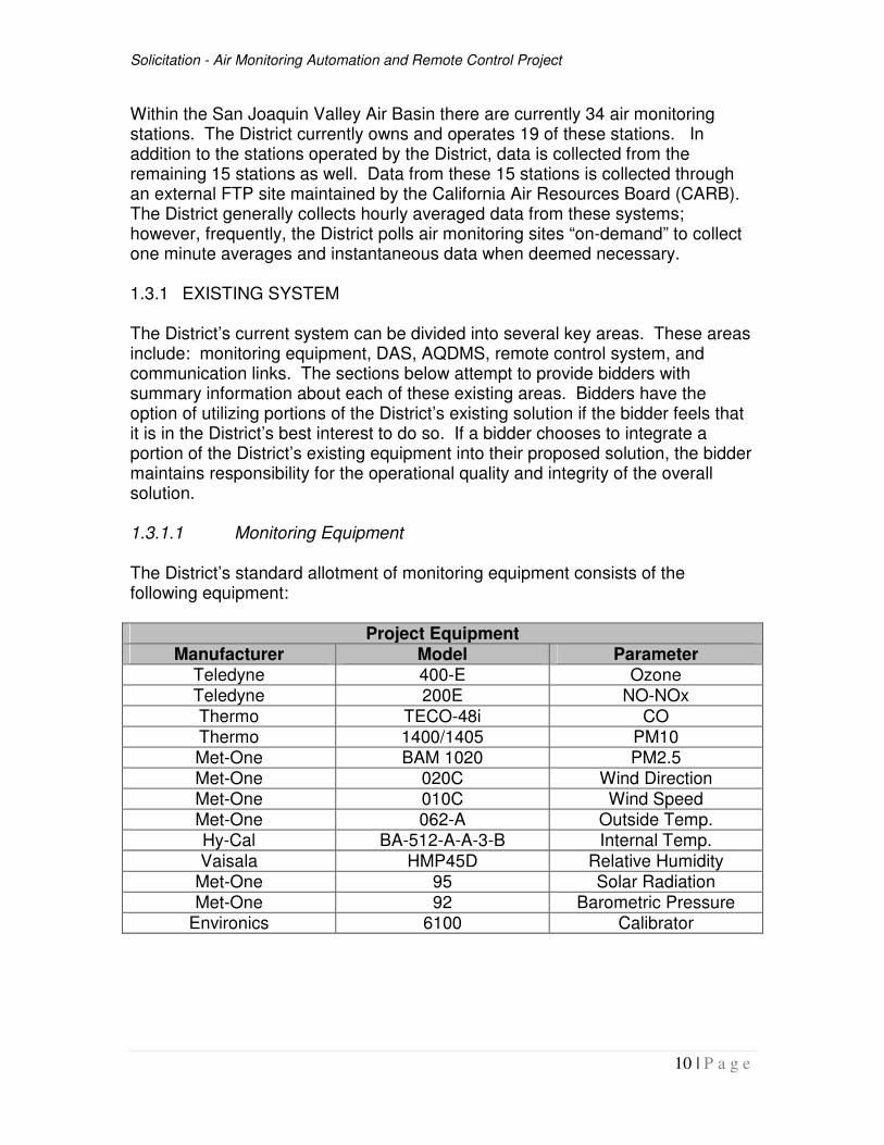
Within the San Joaquin Valley Air Basin there are currently 34 air monitoring stations. The District currently owns and operates 19 of these stations. In addition to the stations operated by the District, data is collected from the remaining 15 stations as well. Data from these 15 stations is collected through an external FTP site maintained by the California Air Resources Board (CARB). The District generally collects hourly averaged data from these systems; however, frequently, the District polls air monitoring sites “on-demand” to collect one minute averages and instantaneous data when deemed necessary. 1.3.1 EXISTING SYSTEM The District’s current system can be divided into several key areas. These areas include: monitoring equipment, DAS, AQDMS, remote control system, and communication links. The sections below attempt to provide bidders with summary information about each of these existing areas. Bidders have the option of utilizing portions of the District’s existing solution if the bidder feels that it is in the District’s best interest to do so. If a bidder chooses to integrate a portion of the District’s existing equipment into their proposed solution, the bidder maintains responsibility for the operational quality and integrity of the overall solution. 1.3.1.1 Monitoring Equipment The District’s standard allotment of monitoring equipment consists of the following equipment:
Project Equipment Manufacturer Model Parameter
Teledyne 400-E Ozone Teledyne 200E NO-NOx
Thermo TECO-48i CO Thermo 1400/1405 PM10 Met-One BAM 1020 PM2.5 Met-One 020C Wind Direction Met-One 010C Wind Speed Met-One 062-A Outside Temp. Hy-Cal BA-512-A-A-3-B Internal Temp.
Vaisala HMP45D Relative Humidity Met-One 95 Solar Radiation Met-One 92 Barometric Pressure
Environics 6100 Calibrator
Solicitation - Air Monitoring Automation and Remote Control Project
11 | P a g e
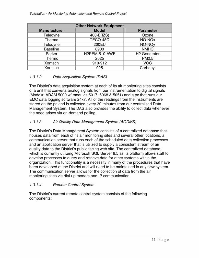
Other Network Equipment Manufacturer Model Parameter
Teledyne 400-E(IZS) Ozone
Thermo TECO-48C NO-NOx Teledyne 200EU NO-NOy Baseline 8900 NMHC Parker H2PEM-510-AWF H2 Generator Thermo 2025 PM2.5 Xontech 910-912 VOC
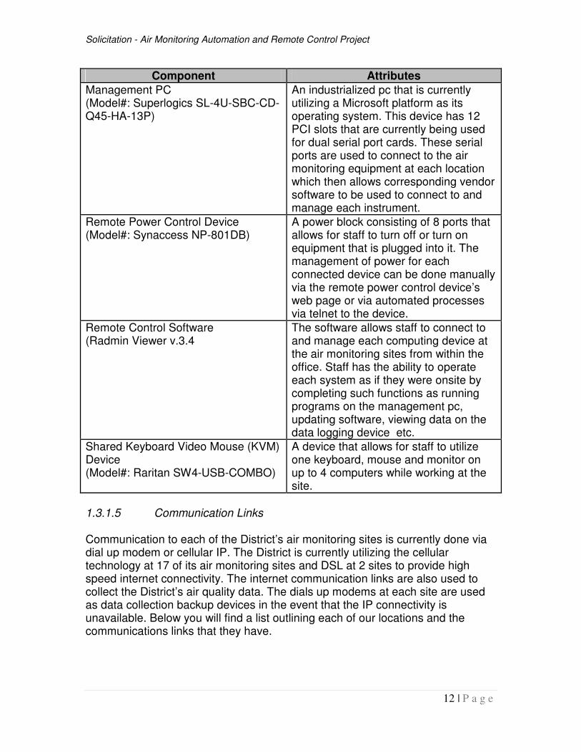
Xontech 925 Carbonyl 1.3.1.2 Data Acquisition System (DAS) The District’s data acquisition system at each of its air monitoring sites consists of a unit that converts analog signals from our instrumentation to digital signals (Model#: ADAM 5000 w/ modules 5017, 5068 & 5051) and a pc that runs our EMC data logging software 24x7. All of the readings from the instruments are stored on the pc and is collected every 30 minutes from our centralized Data Management System. The DAS also provides the ability to collect data whenever the need arises via on-demand polling. 1.3.1.3 Air Quality Data Management System (AQDMS) The District’s Data Management System consists of a centralized database that houses data from each of its air monitoring sites and several other locations, a communication server that runs each of the scheduled data collection processes and an application server that is utilized to supply a consistent stream of air quality data to the District’s public facing web site. The centralized database; which is currently utilizing Microsoft SQL Server 6.5 as its platform allows staff to develop processes to query and retrieve data for other systems within the organization. This functionality is a necessity in many of the procedures that have been developed at the District and will need to be maintained in any new system. The communication server allows for the collection of data from the air monitoring sites via dial-up modem and IP communication. 1.3.1.4 Remote Control System The District’s current remote control system consists of the following components:
Solicitation - Air Monitoring Automation and Remote Control Project
12 | P a g e
Component Attributes
Management PC (Model#: Superlogics SL-4U-SBC-CD-Q45-HA-13P)
An industrialized pc that is currently utilizing a Microsoft platform as its operating system. This device has 12 PCI slots that are currently being used for dual serial port cards. These serial ports are used to connect to the air monitoring equipment at each location which then allows corresponding vendor software to be used to connect to and manage each instrument.
Remote Power Control Device (Model#: Synaccess NP-801DB)
A power block consisting of 8 ports that allows for staff to turn off or turn on equipment that is plugged into it. The management of power for each connected device can be done manually via the remote power control device’s web page or via automated processes via telnet to the device.
Remote Control Software (Radmin Viewer v.3.4
The software allows staff to connect to and manage each computing device at the air monitoring sites from within the office. Staff has the ability to operate each system as if they were onsite by completing such functions as running programs on the management pc, updating software, viewing data on the data logging device etc.
Shared Keyboard Video Mouse (KVM) Device (Model#: Raritan SW4-USB-COMBO)
A device that allows for staff to utilize one keyboard, mouse and monitor on up to 4 computers while working at the site.
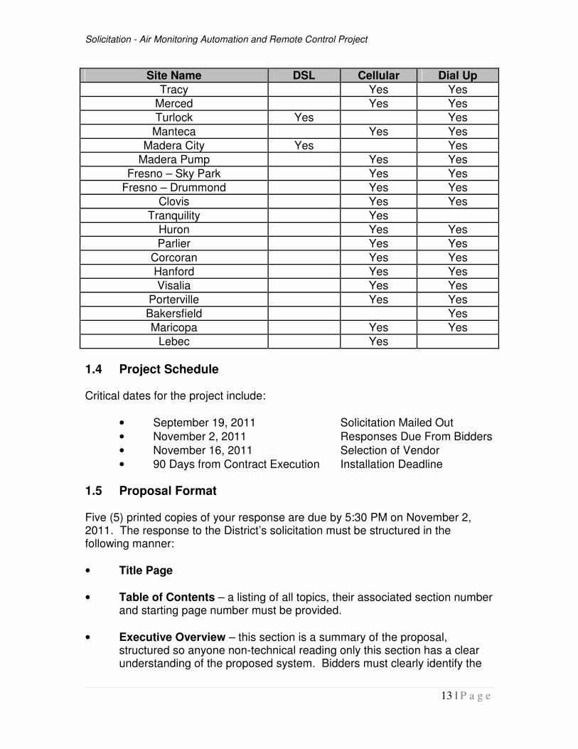
1.3.1.5 Communication Links Communication to each of the District’s air monitoring sites is currently done via dial up modem or cellular IP. The District is currently utilizing the cellular technology at 17 of its air monitoring sites and DSL at 2 sites to provide high speed internet connectivity. The internet communication links are also used to collect the District’s air quality data. The dials up modems at each site are used as data collection backup devices in the event that the IP connectivity is unavailable. Below you will find a list outlining each of our locations and the communications links that they have.
Solicitation - Air Monitoring Automation and Remote Control Project
13 | P a g e
Site Name DSL Cellular Dial Up
Tracy Yes Yes
Merced Yes Yes
Turlock Yes Yes
Manteca Yes Yes
Madera City Yes Yes
Madera Pump Yes Yes
Fresno – Sky Park Yes Yes
Fresno – Drummond Yes Yes
Clovis Yes Yes
Tranquility Yes
Huron Yes Yes
Parlier Yes Yes
Corcoran Yes Yes
Hanford Yes Yes
Visalia Yes Yes
Porterville Yes Yes
Bakersfield Yes
Maricopa Yes Yes
Lebec Yes
1.4 Project Schedule Critical dates for the project include:
• September 19, 2011 Solicitation Mailed Out
• November 2, 2011 Responses Due From Bidders
• November 16, 2011 Selection of Vendor
• 90 Days from Contract Execution Installation Deadline
1.5 Proposal Format Five (5) printed copies of your response are due by 5:30 PM on November 2, 2011. The response to the District’s solicitation must be structured in the following manner:
• Title Page
• Table of Contents – a listing of all topics, their associated section number and starting page number must be provided.
• Executive Overview – this section is a summary of the proposal, structured so anyone non-technical reading only this section has a clear understanding of the proposed system. Bidders must clearly identify the
Solicitation - Air Monitoring Automation and Remote Control Project
14 | P a g e
benefits afforded the District through the installation of the proposed system.
NOTE: The following must be included in the format presented in Section 2.0 and beyond. Each proposal should include the stated question and then present the answer immediately following the question. All proposals and responses should be typewritten. Photocopied and handwritten responses will not be accepted. An electronic version of the solicitation has been posted on the District website at http://www.valleyair.org/RFPs/RFP.htm.
• Vendor Questionnaire – this section presents a series of questions about the bidder, subcontractors, manufacturers, and maintainers of the proposed system. This section also contains reference and insurance information.
• Technical Specifications – the purpose of this section is to provide the proposal evaluation team sufficient information to assess the proposed system. Standard and optional features must be clearly delineated. Bidders must indicate compliance or noncompliance with all requirements. Answers must follow immediately behind the questions.
• Delivery and Installation – this section identifies the tasks and timeframes necessary for successful completion of this project. Task responsibilities must be clearly delineated; necessary timeframes for all tasks must be included. These items will become part of the final contract. The presented project plan must agree with the District’s overall project schedule included in this solicitation.
• Vendor Service – this section describes the maintenance and service options available to the District.
• Configuration/Pricing – this section identifies the all-inclusive fee to be charged for this project, with specific materials, labor, and other expenses contained within the all-inclusive fee. A detailed bill of materials (containing manufacturer, part numbers, product description, quantity, unit price, and price extension) should be included. This section should be divided by functional area (client/server DBMS system (back-end), application software (front-end), modem communication services, desktop clients, etc., remote connection/control (controllers, valves, manifolds, etc.)), because the District may wish to implement a subset of the entire proposal.
• Financial Requirements – this section provides the bidder’s proposed arrangements for system procurement.
Solicitation - Air Monitoring Automation and Remote Control Project
15 | P a g e
• Appendix – bidders should use this section for any system or network diagrams.
• A separate binder should be used for associated product brochures, product evaluation or testimonial reports, published articles, catalogs, etc.
2.0 PERFORMANCE REQUIREMENTS & TECHNICAL SPECIFICATIONS The following sections detail the vendor, hardware, software, and wiring requirements of the new system. All responses must state the extent to which the quoted system meets, exceeds, or fails to meet the stated requirements. Please address all items. If an item is not applicable to your proposal, respond with “N/A”.
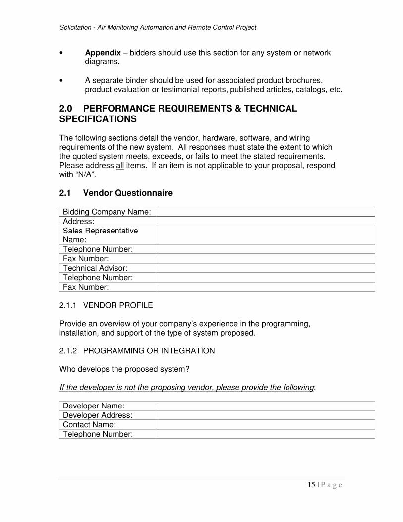
2.1 Vendor Questionnaire Bidding Company Name:
Address: Sales Representative Name:
Telephone Number: Fax Number: Technical Advisor: Telephone Number: Fax Number:
2.1.1 VENDOR PROFILE Provide an overview of your company’s experience in the programming, installation, and support of the type of system proposed. 2.1.2 PROGRAMMING OR INTEGRATION Who develops the proposed system? If the developer is not the proposing vendor, please provide the following: Developer Name: Developer Address: Contact Name: Telephone Number:
Solicitation - Air Monitoring Automation and Remote Control Project
16 | P a g e
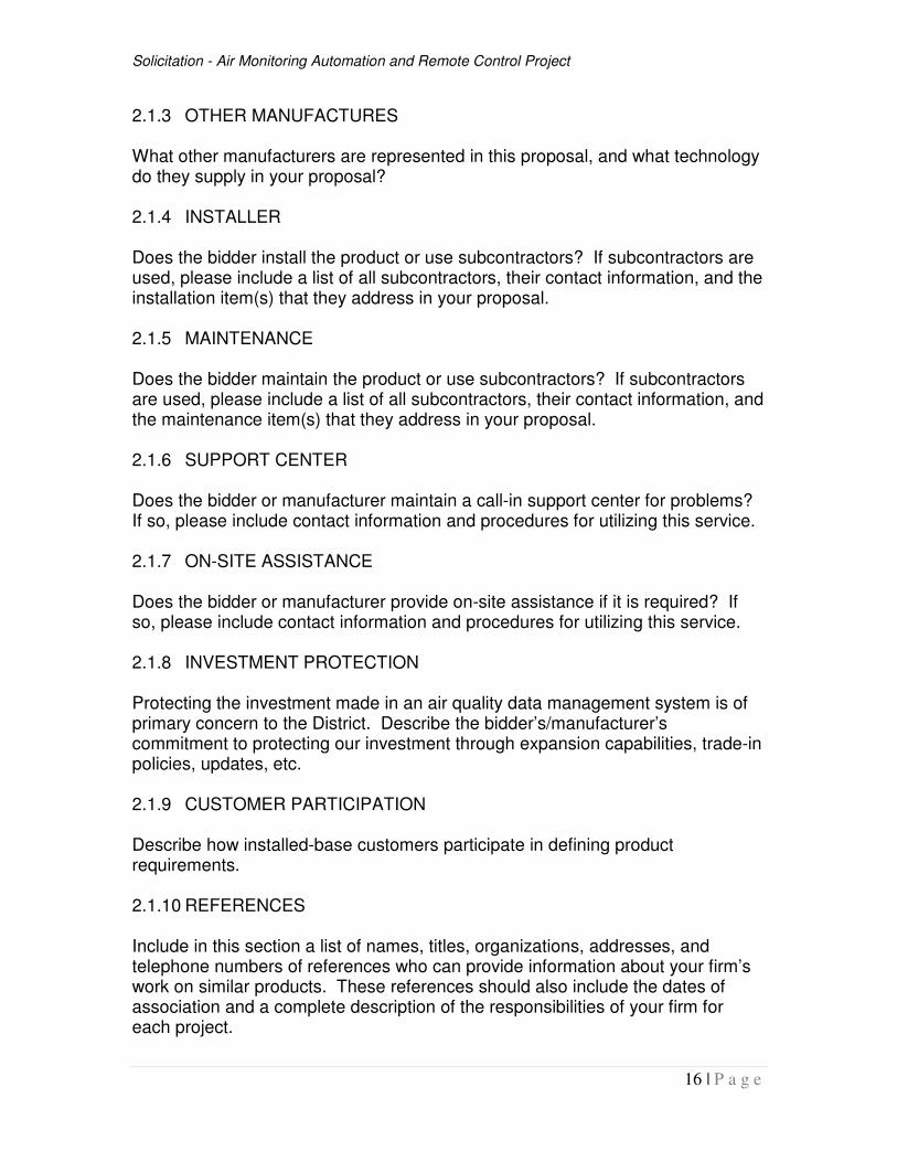
2.1.3 OTHER MANUFACTURES What other manufacturers are represented in this proposal, and what technology do they supply in your proposal? 2.1.4 INSTALLER Does the bidder install the product or use subcontractors? If subcontractors are used, please include a list of all subcontractors, their contact information, and the installation item(s) that they address in your proposal. 2.1.5 MAINTENANCE Does the bidder maintain the product or use subcontractors? If subcontractors are used, please include a list of all subcontractors, their contact information, and the maintenance item(s) that they address in your proposal. 2.1.6 SUPPORT CENTER Does the bidder or manufacturer maintain a call-in support center for problems? If so, please include contact information and procedures for utilizing this service.
2.1.7 ON-SITE ASSISTANCE Does the bidder or manufacturer provide on-site assistance if it is required? If so, please include contact information and procedures for utilizing this service. 2.1.8 INVESTMENT PROTECTION Protecting the investment made in an air quality data management system is of primary concern to the District. Describe the bidder’s/manufacturer’s commitment to protecting our investment through expansion capabilities, trade-in policies, updates, etc. 2.1.9 CUSTOMER PARTICIPATION Describe how installed-base customers participate in defining product requirements. 2.1.10 REFERENCES Include in this section a list of names, titles, organizations, addresses, and telephone numbers of references who can provide information about your firm’s work on similar products. These references should also include the dates of association and a complete description of the responsibilities of your firm for each project.
Solicitation - Air Monitoring Automation and Remote Control Project
17 | P a g e
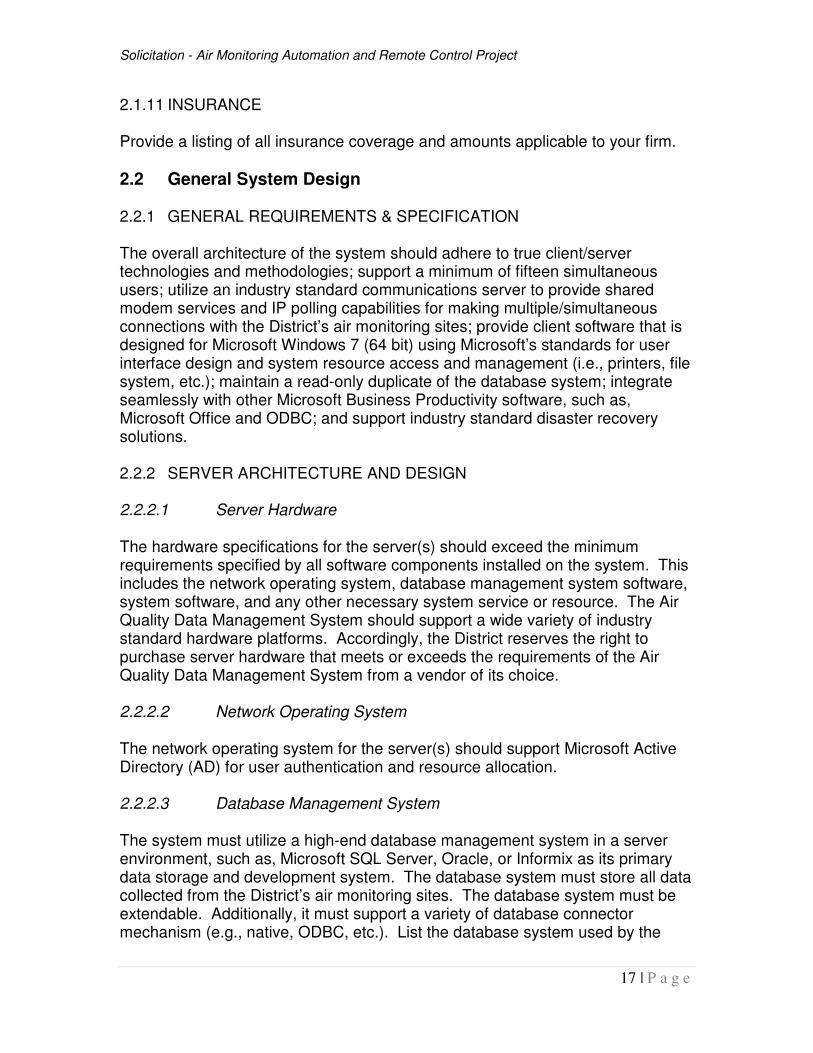
2.1.11 INSURANCE Provide a listing of all insurance coverage and amounts applicable to your firm.
2.2 General System Design 2.2.1 GENERAL REQUIREMENTS & SPECIFICATION The overall architecture of the system should adhere to true client/server technologies and methodologies; support a minimum of fifteen simultaneous users; utilize an industry standard communications server to provide shared modem services and IP polling capabilities for making multiple/simultaneous connections with the District’s air monitoring sites; provide client software that is designed for Microsoft Windows 7 (64 bit) using Microsoft’s standards for user interface design and system resource access and management (i.e., printers, file system, etc.); maintain a read-only duplicate of the database system; integrate seamlessly with other Microsoft Business Productivity software, such as, Microsoft Office and ODBC; and support industry standard disaster recovery solutions. 2.2.2 SERVER ARCHITECTURE AND DESIGN 2.2.2.1 Server Hardware The hardware specifications for the server(s) should exceed the minimum requirements specified by all software components installed on the system. This includes the network operating system, database management system software, system software, and any other necessary system service or resource. The Air Quality Data Management System should support a wide variety of industry standard hardware platforms. Accordingly, the District reserves the right to purchase server hardware that meets or exceeds the requirements of the Air Quality Data Management System from a vendor of its choice. 2.2.2.2 Network Operating System The network operating system for the server(s) should support Microsoft Active Directory (AD) for user authentication and resource allocation. 2.2.2.3 Database Management System The system must utilize a high-end database management system in a server environment, such as, Microsoft SQL Server, Oracle, or Informix as its primary data storage and development system. The database system must store all data collected from the District’s air monitoring sites. The database system must be extendable. Additionally, it must support a variety of database connector mechanism (e.g., native, ODBC, etc.). List the database system used by the
Solicitation - Air Monitoring Automation and Remote Control Project
18 | P a g e
proposed system and the different methods in which a client system could access the database. 2.2.3 NETWORK INFRASTRUCTURE All components of the system that requires a network connection must integrate seamlessly with the District’s network infrastructure. The District’s network infrastructure is 100MB ethernet using TCP/IP protocols running over category 5 unshielded twisted pair wiring. 2.2.4 CLIENT ARCHITECTURE
The client software must integrate seamlessly with Windows 7. It must establish an appropriate connection with the server(s) according to the software configured access levels. Other Microsoft Business Productivity tools (e.g., Microsoft Office, Visual Basic, etc.) must have the capability to access the data stored on the server(s) via supported connector mechanisms (i.e., native, ODBC, etc.).
2.2.5 COMMUNICATION SERVICES The communication services component of the system must have the capability to simultaneously connect, collect, and store data from the different air monitoring sites overseen by the District. This feature must support scheduled connections (software controlled) and manual connections (user controlled). The number of simultaneous connections supported by the communications server should exceed eight connections and must support a minimum of two connections. 2.2.6 DISASTER RECOVERY The system must be compatible with industry standard backup systems for its database system, operating system, and any other system component not mentioned in this solicitation. The system should integrate with the District’s overall backup strategy. The District has standardized on Symantec Backup Exec software for all of its computer systems to establish a unified backup strategy. The system must support Symantec Backup Exec agents for its different software components (i.e., Network Operating System, SQL database, etc.) to incorporate within the District’s overall backup strategy.
2.3 Data Conversion 2.3.1 GENERAL REQUIREMENTS & SPECIFICATIONS The selected vendor must have provisions available to convert existing air quality data from various file formats (i.e., AQS, legacy Aerometric Information Retrieval System (AIRS), Storage and Retrieval of Aerometric Data (SAROAD), text,
Solicitation - Air Monitoring Automation and Remote Control Project
19 | P a g e
Microsoft Access, EMC, etc.). The District prefers AQS file format so that AQS codes are not lost. During the migration process, it is expected that the vendor tests the conversion of data and provides the District with conversion results.
2.4 Application Software The following sections detail the technical requirements and specifications for the software programs which represent the required functional elements of the systems. Air Monitoring and Modeling staff from the Compliance Department and Strategies and Incentives Department will use the AQDMS as described in the following sections. The vendor must perform the administration of the AQDMS and for the purposes of this document, shall be referred to as System Administrator. Authorized staff with the District that will grant security and menu rights and establish/schedule tasks perform shall be referred to as Administers. Authorized staff within the Departments will perform routine operating activities and data related administration, and for the purposes of this document, shall be referred to as Users. 2.4.1 GLOBAL REQUIREMENTS The District has standardized on Microsoft Windows 7 (64 bit) as the desktop operating system. The proposed application software must be designed for the Microsoft Windows environment. The AQDMS must adhere to software development methodologies imposed by Microsoft Windows. The system must take advantage of Microsoft Windows code where possible – examples include Microsoft’s print system, file system, user interface, and desktop management (colors, background, etc.). This list may not be all-inclusive, and therefore, it is up to the vendor to ensure full compatibility with Microsoft Windows 7 (64 bit). 2.4.1.1 User Interface The overall design of the system must be well organized, intuitive, and easy for a user to navigate and use. At a minimum, the system must incorporate a logically organized menu system, clutter free input screens, appropriate field lookup tables, and mouse/keyboard controls. List and describe the major user interface design features inherent within the proposed system (i.e., menu system, button bar, status line, drop down list boxes, radio buttons, check boxes, buttons, etc.). 2.4.1.2 File Structures The primary file structure for storing air quality monitoring data, all calibration data and all text data on the system must be in standard database format, such as SQL Server, Oracle, Informix, etc. The vendor must document and deliver detailed descriptions of the application’s file system. The system must import and export legacy AIRS, AQS file formats, “new” AQS file formats, and ASCII text files.

Solicitation - Air Monitoring Automation and Remote Control Project
20 | P a g e
In addition to normal access methods built into the proposed system, District staff requires direct access to all stored data from other Microsoft Windows based application programs. These include spreadsheet programs, word processors, and database management programs. The file structure provided by the vendor should permit fast, easy, and compatible access by District staff whenever other Microsoft Windows programs are used. Describe the different types of documentation your firm would provide that would detail the overall database layout. Additionally, describe the different ways a client workstation would access the database file system. Lastly, describe how your firm would migrate the District’s existing data over to the proposed system. 2.4.2 AUTOMATION, REMOTE COMMUNICATIONS AND REMOTE CONTROL PROGRAMS The program should include all of the automation, remote connection and remote control capabilities that the District requires. These include, but are not limited to, polling (or otherwise retrieving) data from remote monitoring stations, remote actuation of calibration activities at remote monitoring stations, full remote control and operation of the DAS at a remote monitoring station, retrieval of many types of test files and data, and should include remote viewing of electronic strip chart data from a remote monitoring station. Remote retrieval must be a transparent activity to the users of the program, and must not require direct user intervention, other than setting up a scheduling program that sets the date, time, and type of automatic retrieval activity. Conversely, the system should permit a user to manually contact or interact with a remote monitoring station. After initial setup and configuration, the system should keep track of specific data logger configurations. The system should store a raw copy of collected data that is not modifiable by users. Additionally, the system should have an option to print an unmodified copy of the data being transmitted by the data logger, especially when retrieving data. 2.4.2.1 Polling/Retrieval Polling/retrieval must be divided into two activities. The first is automatic retrieval of one or more of the following: hourly averages, selectable interval averages (1 minute, 5 minute, etc.), and calibration data. The system must allow a user to set up schedules for retrieval all types of data. The second activity is manual retrieval of the same data and information. Manual retrieval must be similar to automatic polling except the user initiates the retrieval on demand and configures extra retrieval intervals (i.e., instantaneous, 1 sec, etc.). The user should be able to initiate retrieval at one site or any combination of sites for one or more specified parameters on one or more specified dates.
Solicitation - Air Monitoring Automation and Remote Control Project
21 | P a g e
2.4.2.2 Polling/Retrieval Compatibility The polling program must have the capability to retrieve data from various data loggers including, but not limited to, data logger models from EMC, ESC, SUMX, Dasibi, and ETC. The program must retrieve hourly averages and calibration data. The data retrieved from all types of loggers should be converted to the system’s standard format. All data must be accessible by the data editor program and all report generating programs. 2.4.2.3 Remote Control of Data Acquisition System (DAS) One of the main features of the remote communications component of the system must be the ability to remotely connect with and fully operate a remote monitoring station’s DAS. This should include full control of all calibration activities, and ability to edit setup/configuration files. 2.4.2.4 Power Cycling of Data Acquisition System (DAS) The system must be able to power cycle the DAS and associated equipment should certain events (like a DAS lock-up) occur. Furthermore, the system must permit the user to manually power cycle the DAS and associated equipment as well. 2.4.2.5 Flagging of Raw Data The system must be able to automatically flag raw air monitoring data in response to calibration events, operating parameters (QA data) from the analyzers being outside of user-defined set-points/thresholds, and air monitoring data values being outside of user-defined set-points/thresholds. Furthermore, the system must automatically flag data based on user entries in the electronic station logbook. 2.4.2.6 Remote Actuation of Calibration Sequences The system must permit the user to schedule, initiate, and control both manual and automatic calibration activities (zero, span and precision) for gaseous analyzers that occur at any remote monitoring station. This includes the calibration of all analyzers at once or any one single analyzer while still collecting ambient data from the other analyzers. This includes daily, quarterly, semi-annual and annual calibrations. The calibrations performed in this manner must meet all applicable USEPA and CARB requirements.
Solicitation - Air Monitoring Automation and Remote Control Project
22 | P a g e
The system may permit the user to schedule, initiate, and control both manual and automatic calibration activities for real-time particulate analyzers and meteorological sensors that occur at any remote monitoring station. The system should permit the user to schedule, initiate, and control both manual and automatic calibration activities for analog-to-digital conversion units (i.e., units similar to the District’s ADAM 5000 units) if such units are a necessary component of the proposed system. 2.4.2.7 Remote Actuation of Manual Calibrations A user of the system must have the capability to manually initiate all calibration activities as described in the previous section. 2.4.2.8 Remote Real-Time Display and Control of Strip Charts The District intends to abandon the use of paper-based strip charts; therefore, the system must have the capacity for electronic strip charts. Furthermore, a user must be able to view electronic strip charts for stored historical data and real-time data once a connection is made with an air monitoring station. The electronic strip chart system must be capable of producing results of the current manual method. 2.4.2.9 Retrieval of Logbook Notes The system must have an electronic station logbook for each station and must have the capability to automatically retrieve logbook files from remote monitoring stations. Logbooks are defined as electronic data files used by air monitoring technicians to record all activities completed while working at a given site. The configuration for this process should allow the administrator to schedule when this process occurs – appropriate fields for scheduling include site name, date, time, and filename. 2.4.2.10 Retrieval of Quality Assurance Information The system must have the capability to automatically retrieve quality assurance information from remote monitoring stations equipped with analyzers that support this feature. Quality Assurance Information is defined as resulting data that indicates an analyzer’s performance and stability from week to week. The configuration for this process should allow an administrator to schedule when this process occurs – appropriate fields for scheduling include site name, date, time and file name.
Solicitation - Air Monitoring Automation and Remote Control Project
23 | P a g e
2.4.2.11 Retrieval of Power Failure Logs The system must log power failures and the capability to automatically retrieve power failure logs from the DAS. The configuration for this process should allow an administrator to schedule when this process occurs – appropriate fields for scheduling include site name, date, time and file name. 2.4.2.12 Retrieval of Strip Chart Data The system must have the capability to automatically retrieve strip chart data from remote monitoring stations. Strip chart information includes channel setup information, direct chart annotations and air monitoring data. The configuration for this process should allow an administrator to schedule when this process occurs – appropriate fields for scheduling include site name, date and/or time range. 2.4.2.13 Retrieval of Hourly Averages The system must have the capability to automatically retrieve hourly average data from remote monitoring stations. The configuration for this process should allow a user to schedule when this process occurs. Appropriate fields for scheduling include site name, date and/or time range. 2.4.2.14 Retrieval of Checklist Data The system may have an electronic monthly checklist for each station and have the capability to automatically retrieve monthly checklist data from remote monitoring stations. Monthly Checklist Data is defined as data that represents a task list of maintenance duties performed by air monitoring technicians during the course of maintaining a site’s equipment. The configuration for this process should allow a user to schedule when this process occurs. Appropriate fields for scheduling include site name, date and/or time range. 2.4.2.15 Retrieval of Calibration Data The system must have the capability to automatically retrieve calibration data from remote monitoring stations. The configuration for this process should allow an administrator to schedule when this process occurs. Appropriate fields for scheduling include site name, date, parameter name, and quantity of calibration data. 2.4.2.16 Time Synchronization The system must be able to automatically synchronize the time clocks for components of the system (AQDMS, DAS, PC, etc.) and the air monitoring equipment (analyzers, calibrators, etc.).
Solicitation - Air Monitoring Automation and Remote Control Project
24 | P a g e
2.4.2.17 Periodic Maintenance Activities
2.4.2.17.1 Interaction with Air Monitoring Analyzers and Equipment The system must be able to connect to and control air monitoring equipment, if allowed by the equipment model, to allow for changes to configuration settings, to download both air monitoring and operational data, and to check for system errors.
2.4.2.17.2 In-line Sampling Filters Currently, staff is required to visit remote stations on a bi-weekly basis to manually change in-line sampling filters for gaseous pollutant analyzers. The system should allow for the automation of in-line sampling filter change outs and should include all necessary equipment (valves, filter holders, tubing, actuators, etc.). At a minimum, this system should handle 3 filters per analyzer. The system must be designed such that all back-pressure and flow requirements established in the USEPA and CARB quality assurance manuals can be met. Furthermore, the system should allow for manual actuation of the filter change in addition to the scheduled changes.
2.4.2.17.3 Introduction of Zero Air
The system should be able to allow a user to remotely introduce zero air to the air monitoring analyzers to check and record operating parameters as needed for maintenance purposes.
2.4.2.17.4 Leak and Pressure Checks
The system should be able to allow a user to remotely perform leak and pressure checks on analyzers. The system should include all necessary equipment (valves, filter holders, tubing, actuators, sensors, etc.). The system must be designed such that all back-pressure and flow requirements established in the USEPA and CARB quality assurance manuals can be met.
2.4.3 DATA EDITOR PROGRAM The system must have a data editor program that is used to review, revise, and validate air monitoring data stored by the system. This section outlines the different required features that must be part of a data editor program. In general, a user must be able to apply a correction factor (addition, subtraction, multiplication, and division) to a specified block of data. Null data codes should not be altered by the application of a correction factor. For each subsection, please indicate whether or not the proposed system fully implements the desired feature.
Solicitation - Air Monitoring Automation and Remote Control Project
25 | P a g e
2.4.3.1 Editing Individual Hourly Values The editor itself should support all editing features found in Microsoft Windows based systems (e.g., cut and paste, field selection using a mouse, etc.). For example, a user should be able to select consecutive and non-consecutive field ranges, row ranges, and column ranges for data replacement.
2.4.3.1.1 Linear Interpolation A user should be able to apply zero and span response corrections to data as a linear interpolated value by inputting a beginning zero or span response value, and an ending zero or span response value. Afterward, the system completes the editing session by applying a linearity interpolated increment to each hourly average between the beginning and ending hours of the data string.
2.4.3.1.2 Slope and Intercept A user must be able to apply slope and intercept corrections to data blocks. This should work in the same manner as the linear interpolation feature with one exception – instead of inputting zero and span responses, the user would input beginning slope and intercept values and ending slope and intercept values. Afterward, the system completes the editing session by applying a linearity incremented factor to each hourly average between the beginning and ending hours of the data string.
2.4.3.1.3 Constant Offsets A user must be able to apply constant offsets to data strings. This also would work in the same manner as the slope and intercept feature with one exception – instead of inputting slope and intercept values, the user would input a constant value. Afterward, the system completes the editing session by adding or subtracting the constant value from all hourly average values in the selected data string.
2.4.3.1.4 Percent Differences A user must be able to apply percent differences to data blocks. This also should work in the same manner as the constant offset feature with one exception – instead of inputting a constant value the user would input a single percent difference. Afterward, the system completes the editing session by factoring this percent difference and applying it to all data values in the selected data string.
2.4.3.1.5 Editing Data Flags A user must be able to apply data flags (i.e., calibration, power failure, etc.) to data blocks. This also should work in the same manner as the percent difference
Solicitation - Air Monitoring Automation and Remote Control Project
26 | P a g e
feature with one exception – instead of inputting a percent difference the user would input a data flag. Afterward, the system completes the editing session by applying the data flag to the selected data block. The system should support more than one data flag because the AQS format allows multiple flags per data point. 2.4.3.2 Printing Data Files The Data Editor must incorporate Microsoft’s print system for the purposes of printing monthly data files displayed by the editor. Printouts must be on numbered sheets with appropriate titles and continuation markers.
2.4.3.2.1 Format of Printed Data When printing monthly diurnal data reports, the printed output should be arranged in a matrix of 24 hours by 31 days. The printout should have appropriate identification information that includes parameter, month, year, station, plus any other standard identification information the District uses for other printouts. Report header information should include AQS site and parameter names and codes. Each row should represent a day’s hourly averages. On the right side of the matrix there should be a 25th column that prints a user selectable item for the row (max, min, USEPA defined averages and sums). This item should disregard any null code values present on that row. Underneath the matrix should be three rows listing statistics for each of the columns above (average, number of valid data points, and max), again disregarding any null code values. In the bottom right of the matrix, aligned with the three rows and the 25th column should be three monthly statistics: monthly average, total valid data points, and max hour. Underneath the three rows should be a single row indicating two items: the day, hour and value of the max hour, plus the day, hour and value of the minimum hour. Reports should include an indication as to whether the data is has been edited/finalized.
2.4.3.2.2 Printout or Display of Results The results may be formatted into a standardized quality assurance review and screening summary report and printed via Microsoft’s print system. It should contain all occurrences of values exceeding the criteria list, their date and hour, and it should also list the appropriate screening criteria. 2.4.3.3 Note System The Data Editor should have a note system that gives the user the ability to document editing activities that were performed during any editing session on each monthly data file. This note system should be a simple note taking system which would store the note and would tag it with the date and time. Other related
Solicitation - Air Monitoring Automation and Remote Control Project
27 | P a g e
data processing programs, such as the “edit trail” program should be able to access these notes to assist in documenting changes during any edit session. 2.4.4 EDIT TRAIL PROGRAM The system must maintain an “edit trail” of all changes made to data. A user must be able to view and print a summary of all edits done to a data file, display user editing notes, and restore data files to their previously edited or unedited state. For each subsection, please indicate whether or not the proposed system fully implements the desired feature. 2.4.4.1 Summary of All Edits Done to Data File The edit trail must display appropriate information (i.e., data file name, month, year, parameter, date changed, etc.) so a user can easily select, review, and back-out changes as necessary. Additionally, the edit trail summary view should have sorting options by date/time, editor’s name, types of edit activity, and edit flags. The edit trail summary view should display the items list below.
2.4.4.1.1 Edit Session The edit trail summary view should display all edit sessions for a given data file, and each edit session should reflect all changes made to the monthly data file.
2.4.4.1.2 Edit Date and Time The edit trail summary view should display a list of all edit sessions for a given data file sorted in either descending or ascending order by the date and time each edit was made.
2.4.4.1.3 Editor’s Name The edit trail summary view should display the name of the person who made the edit(s) associated with the edit session.
2.4.4.1.4 Edit Activity The edit trail summary view should describe the type of edit that was made during each edit session.
2.4.4.1.5 Starting and Ending Day and Hour The edit trail summary view should indicate the starting and ending day and hour covered by the edit.
Solicitation - Air Monitoring Automation and Remote Control Project
28 | P a g e
2.4.4.1.6 Starting Value The edit trail summary view should indicate the initial or starting value applied during the edit. This would be appropriate when an edit was made to a string of hourly average values.
2.4.4.1.7 Ending of Final Edited Value The edit trail summary view should indicate the ending or final edited value applied during each edit session.
2.4.4.1.8 Flags The edit trail summary view should indicate the presence of any flag associated with the edited value or time interval.
2.4.4.1.9 Display of User Editing Notes The edit trail summary view should indicate the presence or absence of editor notes.
2.4.4.1.10 Restoration to Previously Edited or Unedited State A qualified user should be able to restore a monthly data file to any previously edited or unedited state. Like all other editing sessions, this action would be recorded in the edit trail summary log.
2.4.4.1.11 Printing Edit Trail Summary The user should be able to print the edit trail summary to any system printer. 2.4.5 QUALITY ASSURANCE PROGRAM The system should include a full featured quality assurance program that enables a user to electronically maintain historical information regarding the performance and stability as well as the current and historical location of the different analyzers installed and maintained by the District. For each subsection, please indicate whether or not the proposed system fully implements the desired feature. 2.4.5.1 Data Screening Program The system should incorporate a comprehensive quality assurance data-screening program. It must perform a complete quality assurance screening and review of all monthly data files residing on the system. The quality assurance
Solicitation - Air Monitoring Automation and Remote Control Project
29 | P a g e
program should perform at least twelve different types of data review and screening functions. At a minimum, it should review and screen for:
• Data values over a specified setting/value
• Data values under a specified setting/value
• Data values which do not change for X number of hours
• Data values exceeding the rate of change criteria set by the data logger at the remote monitoring station
• A parameter that is greater than a second parameter for any hour in the month
• A parameter that is less than a second parameter for any hour in the month
• Data values exceeding the full-scale range of the data logger at a remote monitoring station
• District representativeness criteria The quality assurance program should have the capability to print reports summarizing the results of the screening process. The print functions should integrate with Microsoft Windows print system. 2.4.5.2 Preventative Maintenance Schedule Program The system should have a comprehensive preventative maintenance scheduling program. This program may keep track of a wide range of preventative maintenance schedules and tasks and alert staff when maintenance is due at any given air monitoring station. The preventative maintenance program should sort tasks and schedules by site, assigned technician, date, and activity type. A user may be able to view and print a maintenance worksheet that is used to log all maintenance activities. 2.4.5.3 Calibration Summary Reports The system should have a program that retrieves (automatic or manual) calibration data from data loggers at the remote monitoring stations. The system should include pre-defined standard reports. Additionally, the system should include a report writer so a user is able to create custom reports.
2.4.5.3.1 Standard Reports There should be a standard report that users print.
2.4.5.3.2 Calibration Summary Report There should be a multipoint calibration summary report that users print.
Solicitation - Air Monitoring Automation and Remote Control Project
30 | P a g e
2.4.5.3.3 Theoretical vs. Actual Calibration Data Report The system should include a report that compares actual versus theoretical values for calibration data (zeros, precisions, and high spans). The report format should include fields for site name, date, parameter, zero value, precision value (both actual and theoretical), offset for precision correction, and its percent error. 2.4.5.4 Precision Statistics Report The system should have the capability to generate and print precision statistics reports. The calibration data used to generate this report must be stored by the system. Normally, calibration data results would be retrieved daily according to a schedule established by an administrator and/or system user. At a minimum, the precision statistics report should contain the following information.
2.4.5.4.1 Station Name and Pollutant The precision statistics report must display the name of the station where the precision calibrations were obtained and the pollutant associated with each precision calibration.
2.4.5.4.2 Number and Date of Precision Calibrations The precision statistics report must display the number of precision calibrations performed during the quarter for each pollutant at the site. The report may also display the date each precision check was performed.
2.4.5.4.3 Baseline Zero The precision statistics report must indicate if a zero offset was applied to the calibration data. If a zero offset was applied, the zero offset value must be listed in the report.
2.4.5.4.4 Net Data Logger Response After Corrections The precision statistics report must indicate the net data logger response after zero and/or span corrections that had been applied to the calibration data.
2.4.5.4.5 Net Data Logger Response with No Corrections If no corrections were applied to the calibration data, the net data logger response with no corrections must be listed on the report.
2.4.5.4.6 True Concentration
Solicitation - Air Monitoring Automation and Remote Control Project
31 | P a g e
The precision statistics report should indicate the true concentration of the precision calibration.
2.4.5.4.7 Net Data Logger Percent Difference The precision statistics report should indicate the net data logger percent difference for the precision calibration.
2.4.5.4.8 Average Percent Difference The precision statistics report must have the ability to calculate the average percent difference of all precision calibrations performed on a specific pollutant throughout a quarter. The quarterly precision statistics report must also display the average percent difference with the format of the report.
2.4.5.4.9 Standard Deviation The precision statistics report must have the ability to calculate the standard deviation of the average percent difference of all precision calibrations performed on a specific pollutant throughout a quarter. The quarterly precision statistics report must also display the standard deviation with the format of the report.
2.4.5.4.10 Lower and Upper Probability Limit The precision statistics report must have the ability to calculate the lower and upper probability limits of the average percent difference of all precision calibrations performed on a specific pollutant throughout a quarter. The quarterly precision statistics report must also display the lower and upper probability limits within the format of the report. 2.4.5.5 X Bar R Control Charts The system must have the ability to generate X Bar R control charts for tracking calibration statistics data. A user must be able to create, display, and print standard control charts that calculate upper and lower control limits using different time intervals (i.e., weekly, monthly, or annually) for calibration data based on any combination of parameters and sites. 2.4.5.6 Power Failure Summary Reports The system must contain a power failure tracking system that tracks occurrences and duration of power failures. From this information, a user must be able to create, view and print detailed and summary reports. Report examples include:
• Annual power failure summary report that lists each power failure and its duration.
Solicitation - Air Monitoring Automation and Remote Control Project
32 | P a g e
• Detailed power failure report that lists the details of each power failure, such as, start/end date and time, duration in minutes, and quantity (in minutes or hours) of data flagged invalid.
2.4.5.7 Data Statistics Summary Report The system should create a Data Statistics Summary report. This report should summarize the daily and monthly downtime hours for each parameter at a given station. The Data Statistics Summary report should contain the following information:
• Station identification
• Report creation date
• By pollutant and list the hours
• Total downtime per parameter for each day
• Total downtime per parameter for each month
• Monthly recovery rate percentage for each parameter 2.4.5.8 Air Quality Values Relative to Standards The system may create an Air Quality Value Relative to Standards Summary Report. This report must summarize up to the five highest values during a month for all parameters at any given site, which are subject to state of federal standards (i.e., CFR part 40). The Air Quality Value Relative to Standards Summary Report must contain but not be limited to the following information:
• Identifying Information: station name, District station number, and AQS number
• Report creation date
• The X highest values (X to be determined by the user) for each parameter per site based on 1, 2, 3, 8, and 24 hour USEPA defined averages
• State, federal primary and federal secondary standards for each parameter
• Optionally, state health advisory and alert levels
• Total count of exceedances per parameter according to state, federal primary and federal secondary standards.
2.4.5.9 Data Completeness Report The system must create a report to evaluate USEPA data completeness requirements.
Solicitation - Air Monitoring Automation and Remote Control Project
33 | P a g e
2.4.6 STRIP CHART PROGRAM The system must incorporate a full-featured electronic strip chart program that has similar features to a hardware based strip chart printer. The data used to generate the chart must be the original, unmodified data collected from the DAS. The strip chart program must allow a user to view historical or real-time strip chart data formatted to display one-minute averages. For each subsection, please indicate whether or not the proposed system fully implements the desired feature. 2.4.6.1 User Interface The strip chart displays should be realistic in nature, similar to a conventional electro-mechanical strip chart recorder. It must display sub-minute air monitoring data for a range of one to eight parameters. A user must be able to adjust the scaling (i.e., no averaging, one-minute averages, five-minute averages, etc.) and line colors for the strip chart displays. The strip chart program must provide strip chart editing features (i.e., chart annotation). All annotations must be stored along with the chart itself for later retrieval. 2.4.6.2 Vertical or Horizontal Display The strip chart display program must have an option for viewing strip charts in vertical or horizontal attitude. Each strip chart display must contain a legend describing each displayed parameter and its zero and full-scale range in engineering units, and the engineering units themselves. Each strip chart must display a PST (Pacific Standard Time) based time baseline. 2.4.7 ROSE PLOTS The system must create, display, and print rose plots. The system must prepare rose plots for wind direction versus wind speed, and wind direction versus any other aerometric data stored on the system. 2.4.8 FREQUENCY DISTRIBUTIONS The system should create, display and print frequency distribution data for both wind direction versus wind speed, and wind direction versus any other aerometric data stored on the system. 2.4.9 STANDARD REPORTS
Solicitation - Air Monitoring Automation and Remote Control Project
34 | P a g e
The system must display and print Standard Data Summary reports in the following formats – Diurnal Report and the Vendor’s Standard Data Matrix Report form. 2.4.10 AIR QUALITY SYSTEM (AQS) GENERATION PROGRAM The system must have the capability to import and export legacy AIRS and AQS data files as required by the USEPA. A user must be able to configure an AQS export process to include standard AQS identification information. The method for creating an AQS export file must be flexible enough in that it allows a user to select any combination of parameters and/or stations for inclusion in the AQS file. 2.4.11 PRECISION AND ACCURACY REPORTING SYSTEM (PARS)
GENERATION PROGRAM The system must have the capability to generate PARS data files as required by the USEPA. A user must be able to configure a PARS data file to include standard PARS identification information. The method for creating a PARS data file must be flexible enough to allow a user to select any combination of parameters and/or stations on a day-to-day basis for inclusion in the PARS file. 2.4.12 SYSTEM SECURITY The system must contain a multi-level security system in order to prevent unauthorized access to the system, sub-menus, screens and its components. An administrator must have the ability to assign users of the system any combination of access rights (i.e., view, modify, delete, etc.) to the various functions available throughout the system. The security system should support the following features:
• Administrative UserID and Password with full access to system
• User accounts names of any length with associated fields for account expiration date, force periodic password changes after a certain period, grace logins, disable account flag, and access rights
• Group names of any length with the same associated fields as user account names, plus an additional field for member names
• All modifications to data by an end-user must be tracked by the system 2.4.13 ALARM SYSTEM The system must have a comprehensive alarm reporting and notification system. The alarm system should automatically warn via email designated users when specific pollutants reach pre-determined levels (based on alarm thresholds) or analyzer quality assurance data vary from established ranges at remote
Solicitation - Air Monitoring Automation and Remote Control Project
35 | P a g e
monitoring stations. Please indicate whether or not the proposed system fully implements the desired feature listed in this section. 2.4.13.1 Alarm Threshold Tables The administrator or designated user must be able to set and establish thresholds, and afterward the system should compare data collected from the sites against the thresholds and alert system users when an alarm condition has occurred. 2.4.14 FIXED ASSET TRACKING PROGRAM The system should allow the tracking of the current and historical location of fixed assets installed, operated and maintained by the District as part of its air monitoring network. Fixed Assets are defined as analyzers, monitors, sensors, computers, etc. which are operated at each air monitoring station. This program should also include an electronic log to document asset specific comments and be integrated into the electronic station log.
3.0 DELIVERY AND INSTALLATION
3.1 Project Management 3.1.1 PROJECT PLAN Vendors are required to supply a proposed schedule for system implementation, along with a complete description of the key teams responsible for the installation of the system. The proposed schedule must agree with the District’s project schedule listed in section 1.4 of this solicitation. 3.1.2 RESPONSIBILITY MATRIX/SCHEDULE A master project schedule must be included, along with a work responsibility matrix, identifying the tasks the vendor and/or their sub-contractors will perform and the tasks that the District is expected to perform to successfully install the new system.
3.2 Installation Requirements 3.2.1 RESPONSIBILITY The selected vendor is responsible for the complete engineering of the new system and interconnecting facilities. 3.2.2 INITIAL WORK
Solicitation - Air Monitoring Automation and Remote Control Project
36 | P a g e
Vendor will perform system preparation and original system initializations. 3.2.3 CHARGES Charges must be itemized for initial installation and for any and all maintenance agreements.
3.3 Facility Requirements Vendors must furnish all space, power, and environmental requirements for the proposed system. 3.3.1 POWER Specify all power requirements, including any special conditioning or grounding requirements. 3.3.2 HEAT, TEMPERATURE, AND HUMIDITY Vendor must provide heat dissipation for the proposed system, and the recommended safe operating temperature and humidity range for the proposed system. 3.3.3 FLOOR LOADING Vendor must provide complete floor loading requirements.
3.4 Cable Requirements Vendor must provide cables and wiring for all proposed system connections.
3.5 Training 3.5.1 TRAINING REQUIREMENTS The selected vendor must conduct end-user training on District premises, tailored specifically to the District’s particular requirements (e.g., application setup/maintenance, SQL database administration, communication services administration, etc.). 3.5.2 TRAINING PLAN Vendor must also provide an intensive training program and training materials for District personnel who will train future employees.
Solicitation - Air Monitoring Automation and Remote Control Project
37 | P a g e
3.5.3 TRAINING DESCRIPTION For each product application proposed, provide a detailed description of the training the vendor will provide. Specify the cost of this training. 3.5.4 MATERIALS Reference copies of the training materials may be included as part of the bidder’s response to this solicitation.
3.6 System Administration The vendor must provide a complete description of the proposed system’s customer administration capabilities. Include in your response any items outside the administration capabilities of District technical staff.
4.0 VENDOR SERVICE
4.1 Maintenance and Warranty A complete maintenance and warranty agreement must be included as part of the proposal, including all options available for extended coverage and full pricing details for each level of coverage. 4.1.1 ONE YEAR WARRANTY The system and all associated equipment in the proposal must be warranted by the vendor and by the manufacturer to be free of defects in equipment, software, and workmanship for a period of at least one year following system cutover at no additional cost to the District. 4.1.2 DEFECTIVE PARTS During the warranty period and any subsequent maintenance agreement, any defective components shall be repaired or replaced at no cost to the District. 4.1.3 MAINTENANCE PERSONNEL All system maintenance during the warranty period and under any maintenance agreements shall be performed by the successful vendor using personnel employed or subcontracted by the bidder and at no additional cost to the District (other than those charges stipulated to maintain the warranty or maintenance agreement).
Solicitation - Air Monitoring Automation and Remote Control Project
38 | P a g e
4.2 Logistical Support Vendor should identify the contact information for the vendor’s local service centers and the number of service personnel trained on the proposed system. Include in this section any other support levels in the local area available to the District for the maintenance of the proposed system.
4.3 Repair Response 4.3.1 SYSTEM MONITORING The selected vendor should provide routine system monitoring to assure the continued operation of all system components. 4.3.2 REMOTE MONITORING CAPABILITIES The proposal must include a complete description of the vendor’s remote monitoring capabilities, remote diagnostics, and remote repair. 4.3.3 LOCAL MONITORING CAPABILITIES The proposal must include a complete description of the vendor’s local monitoring capabilities, local diagnostics and local repair. 4.3.4 REPAIR COMMITMENT The vendor must include a description of the repair commitment from the time that the trouble is reported to the vendor through the time the trouble is cleared. 4.3.5 48-HOUR RESPONSE During the warranty period, the vendor must supply no more than a 48-hour on-site response to major problems, 24 hours a day, 7 days a week. 4.3.6 MAJOR/MINOR PROBLEMS Vendors must describe their definitions of major and minor problems. 4.3.7 OUTSOURCING SERVICES Describe the outsourcing services the vendor offers customers to administer, manage, and support the system.
Solicitation - Air Monitoring Automation and Remote Control Project
39 | P a g e
4.3.8 PLANNING 4.3.8.1 Preventative Maintenance Explain any services the vendor offers that would assist in disaster avoidance and recovery planning for the proposed system. 4.3.8.2 Spare Parts Availability Describe the availability of spare parts maintained in the local area for critical hardware and software. Include in your response a list of items considered critical. 4.3.8.3 Replacement Time Describe the process and amount of time required for full replacement of the central operating hardware/software of the system, assuming a suitable site exists for locating the replacement components. 4.3.8.4 Emergency Installation How long does it take trained personnel to install and load operating system software and database software if a major disaster destroys the principal node of the system? Explain for remote nodes as well. 4.3.9 IMPLEMENTATION 4.3.9.1 Recovery Plan Explain the available services provided by the vendor to allow for a high level of recovery from disasters (e.g., within 2 hours, 4 hours). Include any associated costs in your response. 4.3.9.2 Replacement Options Describe the options available to the District if a system node is destroyed (e.g., replacement with the next machine on the assembly line, replacement systems available locally, etc.).
5.0 CONFIGURATION/PRICING This section identifies the all-inclusive fee to be charged for this project, with specific materials, labor, and other expenses contained within the all-inclusive fee. A detailed bill of materials (containing manufacturer, part numbers, product description, quantity, unit price, and price extension) should be included. This section should be divided by functional area (client/server DBMS system (back-
Solicitation - Air Monitoring Automation and Remote Control Project
40 | P a g e
end), application software (front-end), modem communication services, desktop clients, etc., remote connection/control (controllers, valves, manifolds, etc.)), because the District may wish to implement a subset of the entire proposal. Vendor must itemize all charges for individually identifiable components of the proposed system, including all associated installation, programming, and cabling. Vendor must include charges for all components required to connect all applications, all design charges, and training charges (application and database administrator, communications administrator, etc.). The vendor should include a discussion of the representativeness of the pricing for this project (on a per station basis) should the pilot be successful and the District wish to move forward with implementation of the proposed system across the District’s entire air monitoring network.
6.0 FINANCIAL REQUIREMENTS
6.1 Payment Schedule Vendor must include payment schedules available with the proposed system.
6.2 Terms and Conditions Vendor must include a copy of standard terms and conditions as part of the system proposal.