focus mechanism for kepler mission - esmats.euesmats.eu/amspapers/pastpapers/pdfs/2008/koski.pdf ·...
TRANSCRIPT
Focus Mechanism for Kepler Mission
Kraig Koski*
Abstract The Focus Mechanism built for the primary mirror on the Kepler mission provides a method for adjustment of the mirror position for the duration of the mission. The Focus Mechanism also provides structural support for the 87 kg primary mirror. The Kepler mission requirements provided some interesting and difficult design tasks for the Focus Mechanism. This paper will describe the development, design, function and testing of the Focus Mechanism.
Introduction The goal of the Kepler mission is to survey our region of the Milky Way Galaxy to detect and characterize hundreds of earth-size and smaller planets near the habitable zone. The habitable zone encompasses the distances from a star where liquid water can exist on a planet’s surface. The transit method will be used for detecting extrasolar planets. A transit is when a planet crosses in front of its star as viewed by an observer, resulting in a small change in the star’s brightness for a repeatable amount of time. Once detected, the planet’s orbital size and mass can be calculated using Kepler’s Third Law of planetary motion (T
2 = R
3). The size of the planet is found from the depth of the transit (how much the brightness of
the star drops) along with the size of the planet’s star. From this information, the planet’s characteristic temperature can be calculated.
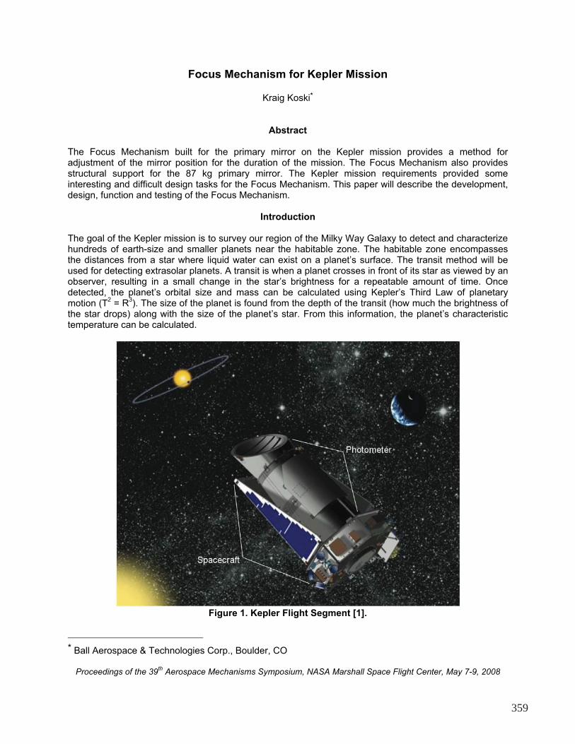
Figure 1. Kepler Flight Segment [1].
* Ball Aerospace & Technologies Corp., Boulder, CO
Proceedings of the 39th Aerospace Mechanisms Symposium, NASA Marshall Space Flight Center, May 7-9, 2008
359
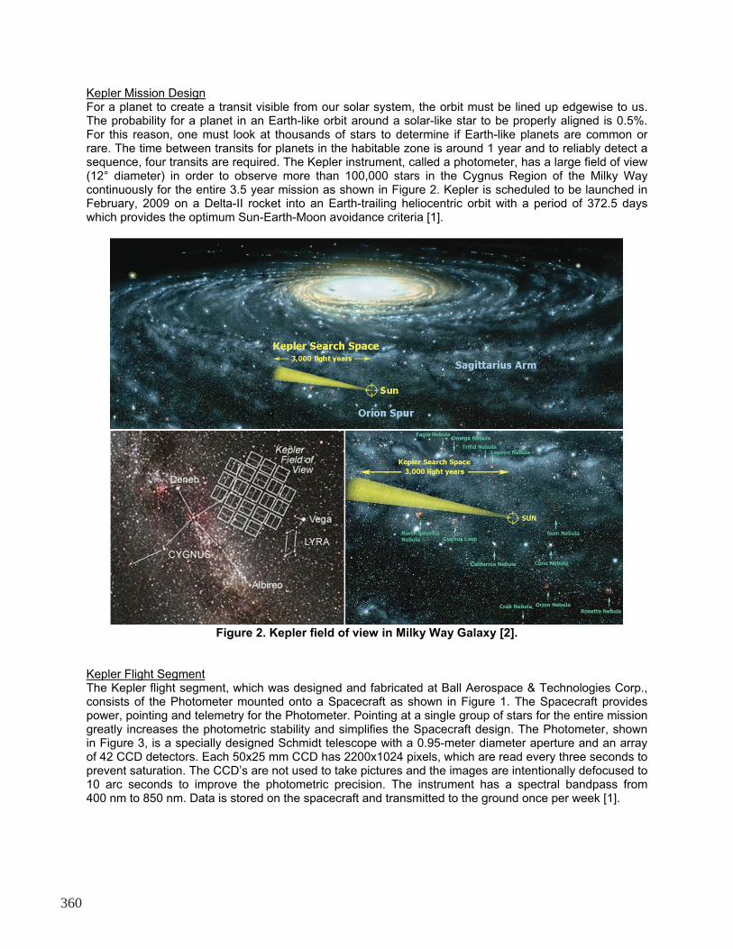
Kepler Mission Design For a planet to create a transit visible from our solar system, the orbit must be lined up edgewise to us. The probability for a planet in an Earth-like orbit around a solar-like star to be properly aligned is 0.5%. For this reason, one must look at thousands of stars to determine if Earth-like planets are common or rare. The time between transits for planets in the habitable zone is around 1 year and to reliably detect a sequence, four transits are required. The Kepler instrument, called a photometer, has a large field of view (12° diameter) in order to observe more than 100,000 stars in the Cygnus Region of the Milky Way continuously for the entire 3.5 year mission as shown in Figure 2. Kepler is scheduled to be launched in February, 2009 on a Delta-II rocket into an Earth-trailing heliocentric orbit with a period of 372.5 days which provides the optimum Sun-Earth-Moon avoidance criteria [1].
Figure 2. Kepler field of view in Milky Way Galaxy [2].
Kepler Flight Segment The Kepler flight segment, which was designed and fabricated at Ball Aerospace & Technologies Corp., consists of the Photometer mounted onto a Spacecraft as shown in Figure 1. The Spacecraft provides power, pointing and telemetry for the Photometer. Pointing at a single group of stars for the entire mission greatly increases the photometric stability and simplifies the Spacecraft design. The Photometer, shown in Figure 3, is a specially designed Schmidt telescope with a 0.95-meter diameter aperture and an array of 42 CCD detectors. Each 50x25 mm CCD has 2200x1024 pixels, which are read every three seconds to prevent saturation. The CCD’s are not used to take pictures and the images are intentionally defocused to 10 arc seconds to improve the photometric precision. The instrument has a spectral bandpass from 400 nm to 850 nm. Data is stored on the spacecraft and transmitted to the ground once per week [1].
360
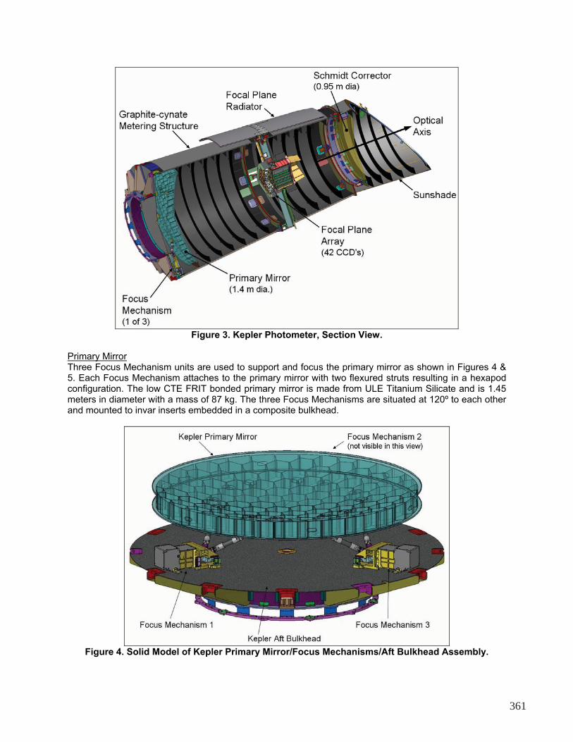
Figure 3. Kepler Photometer, Section View.
Primary Mirror Three Focus Mechanism units are used to support and focus the primary mirror as shown in Figures 4 & 5. Each Focus Mechanism attaches to the primary mirror with two flexured struts resulting in a hexapod configuration. The low CTE FRIT bonded primary mirror is made from ULE Titanium Silicate and is 1.45 meters in diameter with a mass of 87 kg. The three Focus Mechanisms are situated at 120º to each other and mounted to invar inserts embedded in a composite bulkhead.
Figure 4. Solid Model of Kepler Primary Mirror/Focus Mechanisms/Aft Bulkhead Assembly.
361
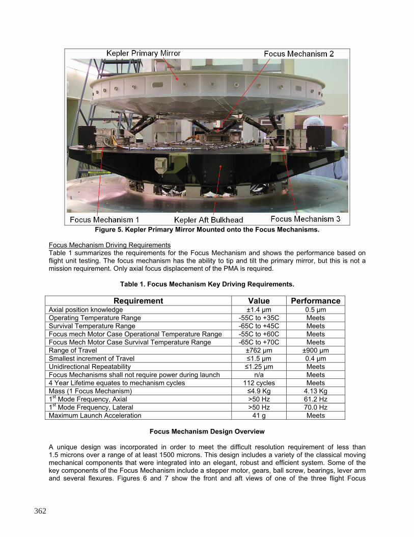
Figure 5. Kepler Primary Mirror Mounted onto the Focus Mechanisms.
Focus Mechanism Driving Requirements Table 1 summarizes the requirements for the Focus Mechanism and shows the performance based on flight unit testing. The focus mechanism has the ability to tip and tilt the primary mirror, but this is not a mission requirement. Only axial focus displacement of the PMA is required.
Table 1. Focus Mechanism Key Driving Requirements.
Requirement Value PerformanceAxial position knowledge ±1.4 μm 0.5 μm Operating Temperature Range -55C to +35C Meets Survival Temperature Range -65C to +45C Meets Focus mech Motor Case Operational Temperature Range -55C to +60C Meets Focus Mech Motor Case Survival Temperature Range -65C to +70C Meets Range of Travel ±762 μm ±900 μm Smallest increment of Travel �1.5 μm 0.4 μm Unidirectional Repeatability �1.25 μm Meets Focus Mechanisms shall not require power during launch n/a Meets 4 Year Lifetime equates to mechanism cycles 112 cycles Meets Mass (1 Focus Mechanism) �4.9 Kg 4.13 Kg 1
st Mode Frequency, Axial >50 Hz 61.2 Hz
1st Mode Frequency, Lateral >50 Hz 70.0 Hz
Maximum Launch Acceleration 41 g Meets
Focus Mechanism Design Overview A unique design was incorporated in order to meet the difficult resolution requirement of less than 1.5 microns over a range of at least 1500 microns. This design includes a variety of the classical moving mechanical components that were integrated into an elegant, robust and efficient system. Some of the key components of the Focus Mechanism include a stepper motor, gears, ball screw, bearings, lever arm and several flexures. Figures 6 and 7 show the front and aft views of one of the three flight Focus
362
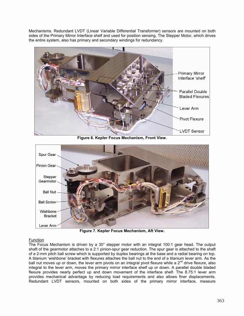
Mechanisms. Redundant LVDT (Linear Variable Differential Transformer) sensors are mounted on both sides of the Primary Mirror Interface shelf and used for position sensing. The Stepper Motor, which drives the entire system, also has primary and secondary windings for redundancy.
Figure 6. Kepler Focus Mechanism, Front View.
Figure 7. Kepler Focus Mechanism, Aft View. Function The Focus Mechanism is driven by a 30° stepper motor with an integral 100:1 gear head. The output shaft of the gearmotor attaches to a 2:1 pinion-spur gear reduction. The spur gear is attached to the shaft of a 2-mm pitch ball screw which is supported by duplex bearings at the base and a radial bearing on top. A titanium ‘wishbone’ bracket with flexures attaches the ball nut to the end of a titanium lever arm. As the ball nut moves up or down, the lever arm pivots on an integral pivot flexure while a 2
nd drive flexure, also
integral to the lever arm, moves the primary mirror interface shelf up or down. A parallel double bladed flexure provides nearly perfect up and down movement of the interface shelf. The 8.75:1 lever arm provides mechanical advantage by reducing load requirements and also allows finer displacements. Redundant LVDT sensors, mounted on both sides of the primary mirror interface, measure
363
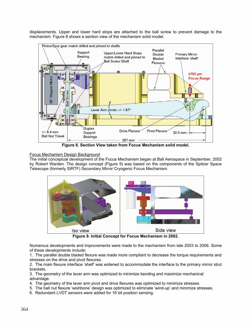
displacements. Upper and lower hard stops are attached to the ball screw to prevent damage to the mechanism. Figure 8 shows a section view of the mechanism solid model.
Figure 8. Section View taken from Focus Mechanism solid model.
Focus Mechanism Design Background The initial conceptual development of the Focus Mechanism began at Ball Aerospace in September, 2002 by Robert Warden. The design concept (Figure 9) was based on the components of the Spitzer Space Telescope (formerly SIRTF) Secondary Mirror Cryogenic Focus Mechanism.
Figure 9. Initial Concept for Focus Mechanism in 2002.
Numerous developments and improvements were made to the mechanism from late 2003 to 2006. Some of these developments include: 1. The parallel double bladed flexure was made more compliant to decrease the torque requirements and stresses on the drive and pivot flexures. 2. The main flexure interface ‘shelf’ was widened to accommodate the interface to the primary mirror strut brackets. 3. The geometry of the lever arm was optimized to minimize bending and maximize mechanical advantage. 4. The geometry of the lever arm pivot and drive flexures was optimized to minimize stresses. 5. The ball nut flexure ‘wishbone’ design was optimized to eliminate ‘wind-up’ and minimize stresses. 6. Redundant LVDT sensors were added for 16 bit position sensing.
364
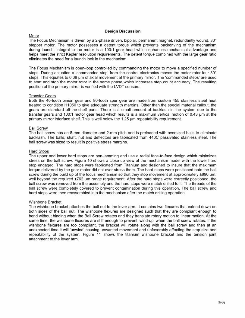
Design Discussion Motor The Focus Mechanism is driven by a 2-phase driven, bipolar, permanent magnet, redundantly wound, 30° stepper motor. The motor possesses a detent torque which prevents backdriving of the mechanism during launch. Integral to the motor is a 100:1 gear head which enhances mechanical advantage and helps meet the strict Kepler resolution requirements. The detent torque combined with the large gear ratio eliminates the need for a launch lock in the mechanism. The Focus Mechanism is open-loop controlled by commanding the motor to move a specified number of steps. During actuation a ‘commanded step’ from the control electronics moves the motor rotor four 30° steps. This equates to 0.38 μm of axial movement at the primary mirror. The ‘commanded steps’ are used to start and stop the motor rotor in the same phase which increases step count accuracy. The resulting position of the primary mirror is verified with the LVDT sensors. Transfer Gears Both the 40-tooth pinion gear and 80-tooth spur gear are made from custom 455 stainless steel heat treated to condition H1050 to give adequate strength margins. Other than the special material callout, the gears are standard off-the-shelf parts. There is a small amount of backlash in the system due to the transfer gears and 100:1 motor gear head which results is a maximum vertical motion of 0.43 μm at the primary mirror interface shelf. This is well below the 1.25 μm repeatability requirement. Ball Screw The ball screw has an 8-mm diameter and 2-mm pitch and is preloaded with oversized balls to eliminate backlash. The balls, shaft, nut and deflectors are fabricated from 440C passivated stainless steel. The ball screw was sized to result in positive stress margins. Hard Stops The upper and lower hard stops are non-jamming and use a radial face-to-face design which minimizes stress on the ball screw. Figure 10 shows a close up view of the mechanism model with the lower hard stop engaged. The hard stops were fabricated from Titanium and designed to insure that the maximum torque delivered by the gear motor did not over stress them. The hard stops were positioned onto the ball screw during the build up of the focus mechanism so that they stop movement at approximately ±890 μm, well beyond the required ±762 μm range requirement. After the hard stops were correctly positioned, the ball screw was removed from the assembly and the hard stops were match drilled to it. The threads of the ball screw were completely covered to prevent contamination during this operation. The ball screw and hard stops were then reassembled into the mechanism after the match drilling operation. Wishbone Bracket The wishbone bracket attaches the ball nut to the lever arm. It contains two flexures that extend down on both sides of the ball nut. The wishbone flexures are designed such that they are compliant enough to bend without binding when the Ball Screw rotates and they translate rotary motion to linear motion. At the same time, the wishbone flexures are stiff enough to prevent ‘wind-up’ when the ball screw rotates. If the wishbone flexures are too compliant, the bracket will rotate along with the ball screw and then at an unexpected time it will ‘unwind’ causing unwanted movement and unfavorably affecting the step size and repeatability of the system. Figure 11 shows the titanium wishbone bracket and the tension joint attachment to the lever arm.
365
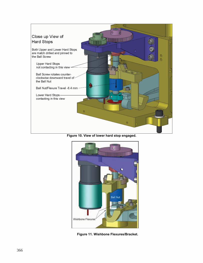
Figure 10. View of lower hard stop engaged.
Figure 11. Wishbone Flexures/Bracket.
366
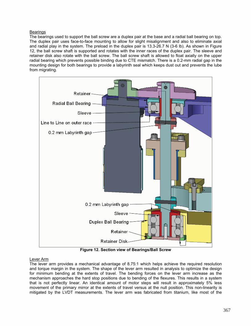
Bearings The bearings used to support the ball screw are a duplex pair at the base and a radial ball bearing on top. The duplex pair uses face-to-face mounting to allow for slight misalignment and also to eliminate axial and radial play in the system. The preload in the duplex pair is 13.3-26.7 N (3-6 lb). As shown in Figure 12, the ball screw shaft is supported and rotates with the inner races of the duplex pair. The sleeve and retainer disk also rotate with the ball screw. The ball screw shaft is allowed to float axially on the upper radial bearing which prevents possible binding due to CTE mismatch. There is a 0.2-mm radial gap in the mounting design for both bearings to provide a labyrinth seal which keeps dust out and prevents the lube from migrating.
Figure 12. Section view of Bearings/Ball Screw
Lever Arm The lever arm provides a mechanical advantage of 8.75:1 which helps achieve the required resolution and torque margin in the system. The shape of the lever arm resulted in analysis to optimize the design for minimum bending at the extents of travel. The bending forces on the lever arm increase as the mechanism approaches the hard stop positions due to bending of the flexures. This results in a system that is not perfectly linear. An identical amount of motor steps will result in approximately 5% less movement of the primary mirror at the extents of travel versus at the null position. This non-linearity is mitigated by the LVDT measurements. The lever arm was fabricated from titanium, like most of the
367
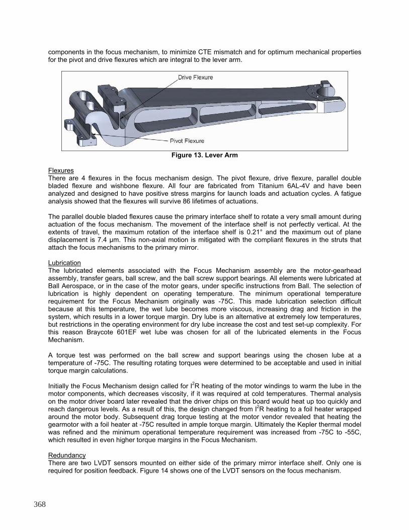
components in the focus mechanism, to minimize CTE mismatch and for optimum mechanical properties for the pivot and drive flexures which are integral to the lever arm.
Figure 13. Lever Arm
Flexures There are 4 flexures in the focus mechanism design. The pivot flexure, drive flexure, parallel double bladed flexure and wishbone flexure. All four are fabricated from Titanium 6AL-4V and have been analyzed and designed to have positive stress margins for launch loads and actuation cycles. A fatigue analysis showed that the flexures will survive 86 lifetimes of actuations. The parallel double bladed flexures cause the primary interface shelf to rotate a very small amount during actuation of the focus mechanism. The movement of the interface shelf is not perfectly vertical. At the extents of travel, the maximum rotation of the interface shelf is 0.21° and the maximum out of plane displacement is 7.4 μm. This non-axial motion is mitigated with the compliant flexures in the struts that attach the focus mechanisms to the primary mirror. Lubrication The lubricated elements associated with the Focus Mechanism assembly are the motor-gearhead assembly, transfer gears, ball screw, and the ball screw support bearings. All elements were lubricated at Ball Aerospace, or in the case of the motor gears, under specific instructions from Ball. The selection of lubrication is highly dependent on operating temperature. The minimum operational temperature requirement for the Focus Mechanism originally was -75C. This made lubrication selection difficult because at this temperature, the wet lube becomes more viscous, increasing drag and friction in the system, which results in a lower torque margin. Dry lube is an alternative at extremely low temperatures, but restrictions in the operating environment for dry lube increase the cost and test set-up complexity. For this reason Braycote 601EF wet lube was chosen for all of the lubricated elements in the Focus Mechanism. A torque test was performed on the ball screw and support bearings using the chosen lube at a temperature of -75C. The resulting rotating torques were determined to be acceptable and used in initial torque margin calculations. Initially the Focus Mechanism design called for I
2R heating of the motor windings to warm the lube in the
motor components, which decreases viscosity, if it was required at cold temperatures. Thermal analysis on the motor driver board later revealed that the driver chips on this board would heat up too quickly and reach dangerous levels. As a result of this, the design changed from I
2R heating to a foil heater wrapped
around the motor body. Subsequent drag torque testing at the motor vendor revealed that heating the gearmotor with a foil heater at -75C resulted in ample torque margin. Ultimately the Kepler thermal model was refined and the minimum operational temperature requirement was increased from -75C to -55C, which resulted in even higher torque margins in the Focus Mechanism. Redundancy There are two LVDT sensors mounted on either side of the primary mirror interface shelf. Only one is required for position feedback. Figure 14 shows one of the LVDT sensors on the focus mechanism.
368
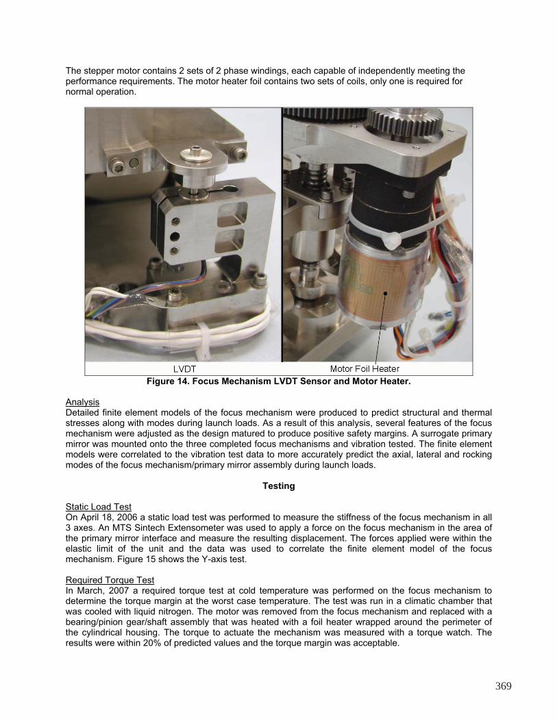
The stepper motor contains 2 sets of 2 phase windings, each capable of independently meeting the performance requirements. The motor heater foil contains two sets of coils, only one is required for normal operation.
Figure 14. Focus Mechanism LVDT Sensor and Motor Heater.
Analysis Detailed finite element models of the focus mechanism were produced to predict structural and thermal stresses along with modes during launch loads. As a result of this analysis, several features of the focus mechanism were adjusted as the design matured to produce positive safety margins. A surrogate primary mirror was mounted onto the three completed focus mechanisms and vibration tested. The finite element models were correlated to the vibration test data to more accurately predict the axial, lateral and rocking modes of the focus mechanism/primary mirror assembly during launch loads.
Testing Static Load Test On April 18, 2006 a static load test was performed to measure the stiffness of the focus mechanism in all 3 axes. An MTS Sintech Extensometer was used to apply a force on the focus mechanism in the area of the primary mirror interface and measure the resulting displacement. The forces applied were within the elastic limit of the unit and the data was used to correlate the finite element model of the focus mechanism. Figure 15 shows the Y-axis test. Required Torque Test In March, 2007 a required torque test at cold temperature was performed on the focus mechanism to determine the torque margin at the worst case temperature. The test was run in a climatic chamber that was cooled with liquid nitrogen. The motor was removed from the focus mechanism and replaced with a bearing/pinion gear/shaft assembly that was heated with a foil heater wrapped around the perimeter of the cylindrical housing. The torque to actuate the mechanism was measured with a torque watch. The results were within 20% of predicted values and the torque margin was acceptable.
369
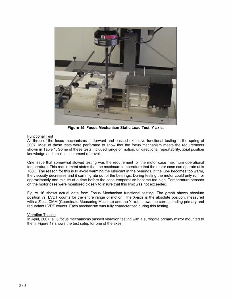
Figure 15. Focus Mechanism Static Load Test, Y-axis.
Functional Test All three of the focus mechanisms underwent and passed extensive functional testing in the spring of 2007. Most of these tests were performed to show that the focus mechanism meets the requirements shown in Table 1. Some of these tests included range of motion, unidirectional repeatability, axial position knowledge and smallest increment of travel. One issue that somewhat slowed testing was the requirement for the motor case maximum operational temperature. This requirement states that the maximum temperature that the motor case can operate at is +60C. The reason for this is to avoid warming the lubricant in the bearings. If the lube becomes too warm, the viscosity decreases and it can migrate out of the bearings. During testing the motor could only run for approximately one minute at a time before the case temperature became too high. Temperature sensors on the motor case were monitored closely to insure that this limit was not exceeded. Figure 16 shows actual data from Focus Mechanism functional testing. The graph shows absolute position vs. LVDT counts for the entire range of motion. The X-axis is the absolute position, measured with a Ziess CMM (Coordinate Measuring Machine) and the Y-axis shows the corresponding primary and redundant LVDT counts. Each mechanism was fully characterized during this testing. Vibration Testing In April, 2007, all 3 focus mechanisms passed vibration testing with a surrogate primary mirror mounted to them. Figure 17 shows the test setup for one of the axes.
370
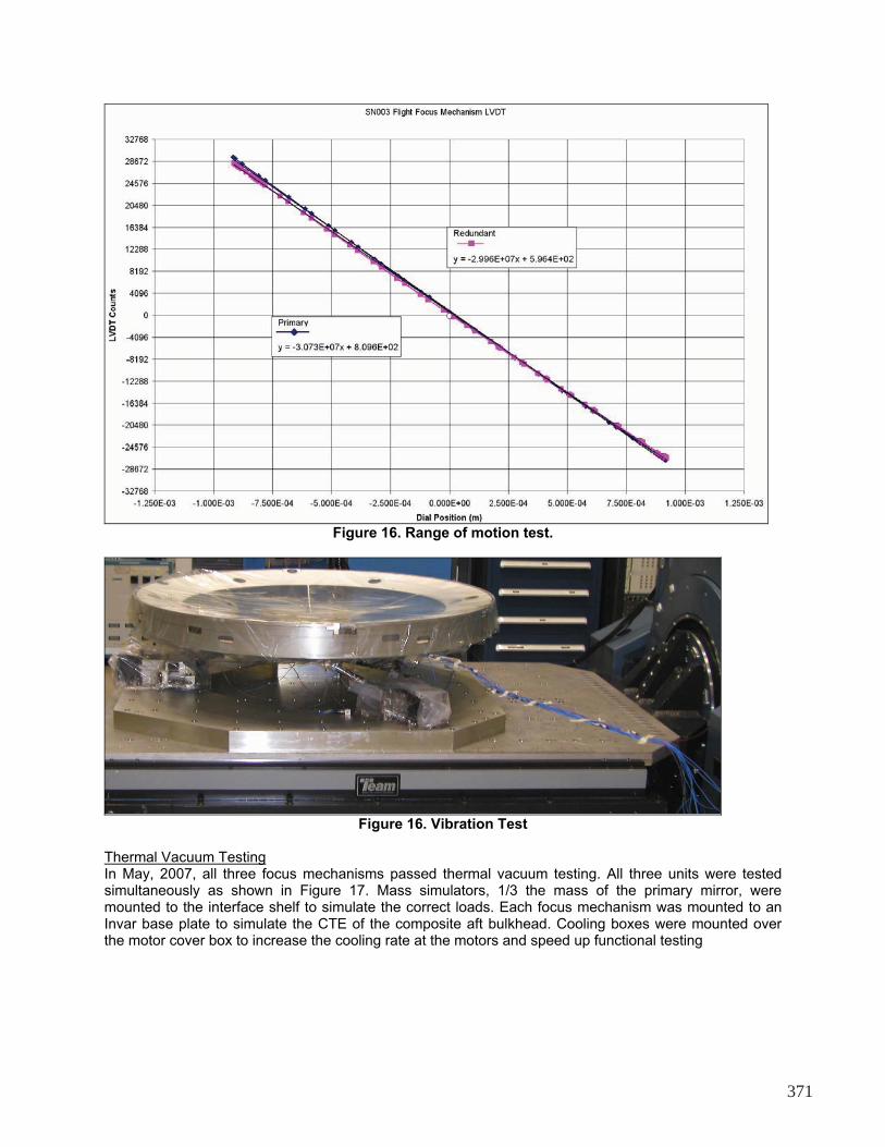
Figure 16. Range of motion test.
Figure 16. Vibration Test
Thermal Vacuum Testing In May, 2007, all three focus mechanisms passed thermal vacuum testing. All three units were tested simultaneously as shown in Figure 17. Mass simulators, 1/3 the mass of the primary mirror, were mounted to the interface shelf to simulate the correct loads. Each focus mechanism was mounted to an Invar base plate to simulate the CTE of the composite aft bulkhead. Cooling boxes were mounted over the motor cover box to increase the cooling rate at the motors and speed up functional testing
371
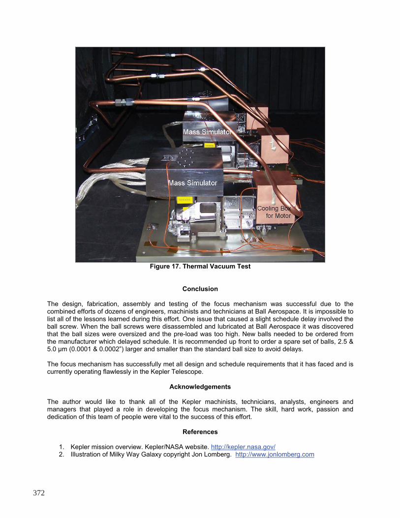
Figure 17. Thermal Vacuum Test
Conclusion
The design, fabrication, assembly and testing of the focus mechanism was successful due to the combined efforts of dozens of engineers, machinists and technicians at Ball Aerospace. It is impossible to list all of the lessons learned during this effort. One issue that caused a slight schedule delay involved the ball screw. When the ball screws were disassembled and lubricated at Ball Aerospace it was discovered that the ball sizes were oversized and the pre-load was too high. New balls needed to be ordered from the manufacturer which delayed schedule. It is recommended up front to order a spare set of balls, 2.5 & 5.0 �m (0.0001 & 0.0002”) larger and smaller than the standard ball size to avoid delays. The focus mechanism has successfully met all design and schedule requirements that it has faced and is currently operating flawlessly in the Kepler Telescope.
Acknowledgements
The author would like to thank all of the Kepler machinists, technicians, analysts, engineers and managers that played a role in developing the focus mechanism. The skill, hard work, passion and dedication of this team of people were vital to the success of this effort.
References
1. Kepler mission overview. Kepler/NASA website. http://kepler.nasa.gov/ 2. Illustration of Milky Way Galaxy copyright Jon Lomberg. http://www.jonlomberg.com
372