fnh usa scar 16s and 17s
TRANSCRIPT

FNH USA
AUtoloAdiNg riFle oWNer'S MANUAl
SCAr 16S ANd 17S

1
11. Ammunition .......................................17
12. Magazine Capacity ............................18
13. Loading ..............................................19
13.1. Loading the Magazine .............19
13.2. Loading the Chamber from the Magazine ...................20
14. Firing .................................................21 14.1. Firing Procedures .....................22 14.2. Malfunctions ............................24
15. Unloading ...........................................25
15.1. Unloading the Rifle ..................25
15.2. Unloading the Magazine ..........2616. Mounting Accessories ........................26
17. Buttstock Module ...............................26
17.1. Folding the Buttstock Module .....................27
17.2. Unfolding the Buttstock Module .....................28
17.3. Adjusting Length of Pull ..........28
17.4. Adjusting the Cheek Rest Height ...................2918. Sights .................................................29 18.1. Explanation of the SCAR 16S Sight System ............................29 18.2. Zeroing .....................................3019. Disassembly .......................................33 19.1. Removal of the Trigger Module .........................34
19.2. Removal of the Buttstock Module .....................35 19.3. Removal of the Moving Parts Assembly ...........35 19.4. Disassembly of the Moving Parts Assembly ...........36 19.5. Removal of the Gas Regulator and Gas Piston.........................38
20. Cleaning and Lubrication ..................39
20.1. Cleaning Procedures ................40 20.2. Cleaning the Trigger Module .........................42 20.3. Cleaning the Magazine ............4321. Assembly ............................................43 21.1. Installation of the Gas Piston and Gas Regulator ...................43 21.2. Assembling the Moving Parts Assembly ...........44 21.3. Installation of the Moving Parts Assembly ...........45 21.4 Installation of the Buttstock Module .....................46 21.5 Installation of the Trigger Module .........................46 21.6. Function Check ........................48
22. Taking Care of the Rifle .....................48
23. Service Policy .....................................49
24. Warranty or Service ............................49
25. Technical Specifications ....................50
Important operating instructions for:
FNH USA SCAr AUtoloAdiNg riFleSIf you have any questions or comments regarding your new firearm, please contact us.
FNH USA, LLC, (703) 288-1292, extension 122 fnhusa.com
Please use the space below to record information about your new firearm.
Model ________________________________________________
Serial Number___________________________________________
Purchased From _________________________________________
Date of Purchase _________________________________________
1. Foreword ...............................................2
2. Contents of the Storage Case .............2
3. Safety and Warranty Notes ..................3
4. Firearm Safety Information..................4
5. Description and Operation.................11
5.1. Description ...............................11
5.2. Operation ..................................14
6. Nomenclature .....................................14
7. Serial Number ....................................14
8. Initial Cleaning ..................................15
9. Operation of the “Safety” Selector ....15
10. Bolt Release .......................................16
10.1. Bolt Release Function ..............17
10.2. Bolt Lock Function ...................17
CoNteNtS

2 3
3. SAFety ANd WArrANty NoteS
like All FireArMS iF HANdled iN A CAreleSS or reCkleSS MANNer tHe SCAr CAN be very dANgeroUS. FAilUre to FolloW tHe iNForMAtioN iN tHiS oWNer’S MANUAl CoUld reSUlt iN SerioUS iNjUry or deAtH.
For that reason, the rifle has been sold under the express understanding that FNH USA declines any responsibility and invalidates any guarantee and liability claims for incidental or consequential damages, injuries, loss of use of property, commercial loss, loss of earnings and profits, resulting in whole or partly from:
• the use of reloaded ammunition • a discharge with criminal intent or through negligence • improper or careless handling • unauthorized servicing • the modification or alteration of the basic rifle design • the use of non-original parts • the modification or alteration of the “safety” devices • the use of incorrect “arms and ammunition” combinations • the use of defective or unsafe ammunition • inadequate care of the rifle (e.g. corrosion, damage.) • disregard of malfunctions • resale in contradiction to legislation • other circumstances beyond our direct and immediate control
Notice! FNH USA reServeS tHe rigHt to reFUSe ServiCiNg A riFle WHiCH HAS beeN ModiFied by reMovAl oF MetAl FroM tHe bArrel, ModiFiCAtioNS oF tHe FiriNg MeCHANiSM ANd/or otHer pArtS, ANd Will, iN SUCH A CASe, AlWAyS reCoMMeNd reStoriNg tHe riFle to itS origiNAl SpeCiFiCAtioNS. pArtS ANd lAbor reqUired For SUCH A reStorAtioN Are pAyAble by tHe oWNer oF tHe riFle.
1. ForeWordWe are pleased that you have chosen a FNH USA SCAR autoloading rifle. The SCAR combines the latest in autoloading rifle design, manufacture and testing methods to create a rifle worthy of the operators of the U.S. Military’s Special Operations Forces. The SCAR represents the highest levels of reliable function, consistent accuracy, comfortable ergonomics and the operating precision and safety expected from an FNH USA firearm.
Unique and simple in design, the rifle is very easy to maintain. With a reasonable amount of care, your SCAR rifle should give you many years of dependable, enjoyable service.
In order to take maximum advantage of the many features of your SCAR rifle, regularly review this owner’s manual.
Please contact us if you have any observations or questions regarding the performance or the operation of your rifle.
Thank you.
2. CoNteNtS oF tHe StorAge CASeThe rifle and its accessories are supplied in a military-style shipping container. The contents of the container include:
• Rifle
• Locking device and two keys (Use the locking device when storing and transporting the rifle. Always keep the keys in a safe place.)
• SCAR 16S: One 30-round magazine (One 10-round magazine where required by law)
SCAR 17S: One 20-round magazine (One 10-round magazine where required by law)
• Owner’s manual

4 5
your firearm’s muzzle in an unsafe direction. See Section 9 for instructions on the operation of this firearm’s “safety.”
Remember, safe gun handling does not stop with your firearm’s mechanical “safety” devices, it starts there. Always treat this firearm with the respect due a loaded, ready-to-fire firearm.
Some firearms do not have a mechanical safety. Many target firearms, lever-action firearms and rifles do not have manual “safety” mechanisms. Therefore it is critical to read and understand the owner’s manual for every firearm which explains the safe operation of the firearm.
While it is a good idea to “test” your firearm’s mechanical “safety” periodically for proper function, never test the “safety” while your firearm is loaded or pointed in an unsafe direction.
3 WHeNever yoU HANdle ANy FireArM, or HANd it to SoMeoNe, AlWAyS opeN tHe ACtioN iMMediAtely ANd viSUAlly CHeCk tHe FireArM’S CHAMber ANd MAgAZiNe to MAke CertAiN tHAt tHe FireArM iS CoMpletely UNloAded. Make certain the firearm does not inadvertently contain any ammunition. Always keep the chamber empty and the “safety” in the on safe position unless shooting is imminent.
If your firearm is equipped with a detachable magazine, be aware that removing the magazine does not mean your firearm is completely unloaded, a cartridge could be in the chamber. Always remove the magazine, open the action and visually inspect the chamber to make certain the firearm is completely unloaded.
4 AlWAyS WeAr eye ANd HeAriNg proteCtioN WHeN SHootiNg. Unprotected, repeated exposure to gunfire can cause hearing damage. Wear ear protectors (shooting earplugs or muffs) to guard against such damage.
4. FireArM SAFety iNForMAtioN
FAilUre to FolloW ANy oF tHe FolloWiNg WArNiNgS CoUld reSUlt iN SerioUS iNjUry or deAtH.
As a firearm owner, you accept a set of demanding responsibilities. How seriously you take these responsibilities can be the difference between life and death.
There is no excuse for careless or abusive handling of any firearm. At all times handle this firearm and all other firearms with intense respect for their power and potential danger.
Please read and understand all of the cautions, warnings, notices, proper handling procedures and instructions outlined in this owner’s manual before using your new firearm.
1 AlWAyS keep tHe MUZZle oF yoUr FireArM poiNted iN A SAFe direCtioN eveN tHoUgH yoU Are CertAiN it iS UNloAded. Never point any firearm at anything you do not intend to shoot. Be extremely alert and aware of all persons and property within the range of your ammunition.
2 Never rely totAlly oN yoUr FireArM’S MeCHANiCAl “SAFety” deviCeS. like ANy MeCHANiCAl deviCe, A “SAFety” CAN SoMetiMeS FAil; it CAN be jArred or iNAdverteNtly MANipUlAted iNto AN UNSAFe CoNditioN.The word “safety” describes a firearm’s trigger block mechanism, sear block mechanism, hammer block mechanism or firing pin block mechanism. Mechanical “safeties” are designed to place your firearm in a safer status, and no guarantee can be made that the firearm will not fire even if the “safety” is in the on safe position. Mechanical “safeties” merely aid safe gun handling and are no excuse for pointing

6 7
8 Store yoUr FireArM ANd AMMUNitioN SepArAtely, Well beyoNd tHe reACH oF CHildreN. Take prudent safeguards to ensure your firearm does not become available to untrained, inexperienced or unwelcome hands. Store all firearms in secure, locked cases or a gun safe. Keep your firearm unloaded when not in use. At all times, comply with local and state laws.
For law enforcement and military personnel, refer to the procedures of your department on storing your firearm.
9 beWAre oF bArrel obStrUCtioNS. Mud, snow and an infinite variety of other objects may inadvertently lodge in a barrel bore. It only takes a small obstruction to cause dangerously increased pressures that can damage your firearm and cause serious injury to yourself and others. beFore CHeCkiNg For A bArrel obStrUCtioN, be CertAiN yoUr FireArM iS CoMpletely UNloAded, tHere iS Not A live CArtridge iN tHe CHAMber ANd tHe “SAFety” iS iN tHe oN SAFe poSitioN. Completely unload the firearm as described in Section 15.1. After assuring yourself that the firearm is completely unloaded, open the breech or action and look through the barrel to be sure it is clear of obstructions. If an obstruction is seen, no matter how small it may be, clean the bore with a cleaning rod and patch as described in Section 20.1. of this owner’s manual.
10 be Alert to tHe SigNS oF AMMUNitioN MAlFUNCtioN. iF yoU deteCt AN oFF SoUNd or ligHt reCoil WHeN A CArtridge iS Fired, do Not loAd ANotHer CArtridge iNto tHe CHAMber. If your firearm fails to fire, keep the muzzle pointed in a safe direction for a minimum of 30 seconds. Carefully open the action and remove the cartridge from the chamber, and completely unload the firearm as described in Section 15.1. If the primer is indented, the defective cartridge should be disposed of in a way that cannot cause harm.
Wear shooting glasses to protect your eyes from flying particles. Allow proper distance (eye relief) between a scope and your eye when firing a scoped rifle or shotgun. Do not use unorthodox shooting methods that could cause the rearward travel of the slide or bolt of a firearm to contact your eyes, face or hands. Always keep a safe distance between the muzzle of your firearm and any persons nearby, as muzzle blast, debris and ejecting shells could inflict serious injury.
Always wear eye protection when disassembling and cleaning your rifle to prevent the possibility of springs, spring-tensioned parts, solvents or other agents from contacting your eyes.
5 keep All FireArMS UNloAded dUriNg trANSport, eveN WHeN Stored iN A HolSter, gUN CASe, SCAbbArd or otHer CoNtAiNer. For law enforcement and military personnel, refer to the procedures of your department on carrying a loaded firearm.
6 droppiNg or jArriNg A loAded FireArM CAN CAUSe AN ACCideNtAl diSCHArge. This can occur even with the “safety” in the on safe position or the hammer in the decocked position. Be extremely careful while hunting or during any shooting activity, to avoid dropping any firearm.
7 SHootiNg FroM elevAted SUrFACeS iS dANgeroUS.Doing so may increase the risk of mishandling a firearm. The following rules should always be observed. Always make certain that the surface being used is safe and stable. Always make certain that your firearm is unloaded when it is being taken up and down from the surface. Always make certain that your firearm is not dropped from the surface, or dropped while it is being taken up or down from the surface. Remember, a loaded firearm may discharge when dropped, even with the “safety” in the on safe position.
8 9
14 MAke SUre oF AdeqUAte veNtilAtioN iN tHe AreA tHAt yoU diSCHArge A FireArM. leAd expoSUre CAN oCCUr FroM diSCHArgiNg FireArMS iN poorly veNtilAted AreAS, CleANiNg FireArMS or HANdliNg AMMUNitioN.Lead is a substance that has been known to cause birth defects, reproductive harm and other serious injury. Wash hands thoroughly after exposure to ammunition or after cleaning a firearm.
15 do Not SNAp tHe FiriNg piN oN AN eMpty CHAMber: tHe CHAMber MAy Not be eMpty!Treat every firearm with the respect due to a loaded firearm, even though you are certain the firearm is unloaded.
16 keep yoUr FiNgerS AWAy FroM tHe trigger At All tiMeS UNtil SHootiNg iS iMMiNeNt.
17 be SUre oF yoUr tArget ANd bACkStop, pArtiCUlArly dUriNg loW ligHt periodS. Know the range of your ammunition. Never shoot at water or hard objects.
18 AlWAyS UNloAd yoUr FireArM’S CHAMber beFore CroSSiNg A FeNCe, CliMbiNg A tree, jUMpiNg A ditCH or NegotiAtiNg otHer obStACleS. Never place your firearm on or against a fence, tree, car or other similar object. Refer to Section 15.1. for unloading procedures.
For law enforcement and military personnel, refer to the procedures of your department.
19 be deFeNSive ANd oN gUArd AgAiNSt UNSAFe gUN HANdliNg AroUNd yoU ANd otHerS. Don’t be timid when it comes to gun safety. If you observe other shooters violating any of these safety precautions, politely suggest safer handling practices.
If the primer is not indented, your firearm should be examined by a qualified gunsmith and the cause of the malfunction corrected before further use. Glance down the barrel to make sure that there are no obstructions in the barrel. If there is an obstruction, completely clear the barrel before loading and firing again. Failure to follow these instructions can cause extensive damage to your firearm and possible serious injury to yourself and others.
11 Never iNSert A CArtridge oF tHe iNCorreCt CAliber iNto ANy FireArM. The caliber of your firearm is marked on the upper receiver and barrel. Store all cartridges of different calibers in completely separate and well-marked containers. Never store cartridges of mixed calibers in a common container or in your pockets. See Section 11 for more information on the correct ammunition for your firearm.
12 exAMiNe every CArtridge yoU pUt iN yoUr FireArM. We assume no responsibility for the use of unsafe or improper firearm and ammunition combinations or damage or injury caused by damaged ammunition. It is your responsibility to read and heed all warnings in this owner’s manual and on ammunition boxes. See Section 11 for more information on the correct ammunition for your firearm.
13 USe oNly SAAMi Approved AMMUNitioN. The barrel and action of this rifle have been made with substantial safety margins over the pressures developed by established American commercial loads. Nevertheless, we can assume no liability for incidents which occur through the use of cartridges of nonstandard dimensions or which develop pressures in excess of commercially available ammunition which has been loaded in accordance with standards established by the Sporting Arms and Ammunition Manufacturers’ Institute (SAAMI).

10 11
We cannot assume any responsibility for injuries suffered or caused by unauthorized servicing, alterations or modifications of FNH USA firearms.
25 We reServe tHe rigHt to reFUSe ServiCe oN FireArMS tHAt HAve beeN Altered, Added to or SUbStANtiAlly CHANged. Removal of metal from the barrel or modifications of the firing mechanism and/or operating parts may lead to a refusal of service on such firearms. We will charge the owner for parts and labor to return the firearm to original FNH USA specifications.
do Not, UNder ANy CirCUMStANCeS, Alter tHe trigger, SAFety or otHer pArtS oF tHe FiriNg MeCHANiSM oF tHiS or ANy otHer FireArM. FAilUre to obey tHiS WArNiNg MAy reSUlt iN iNjUry or deAtH to yoUrSelF or otHerS.
B e c a r e f u l !
5. deSCriptioN ANd operAtioN5.1. deSCriptioN
The FNH USA SCAR is a gas-operated, semi-automatic repeating rifle. SCAR rifles are a direct result of the U.S. Military’s search for a modular battle rifle that is easy to use and extremely reliable. SCAR rifles have been developed using the latest computer software, extensive materials testing, real-world research and end user assessments from special operations forces operators. This information has culminated in the next generation of technologically-advanced rifles. To make the transition to the SCAR rifles easier, the ergonomically-designed pistol grip stock is designed with dimensions to suit operators familiar with the M16/M4 platform.
20 be CertAiN yoUr FireArM iS UNloAded beFore CleANiNg. Because so many gun accidents occur when a firearm is being cleaned, special and extreme care should be taken to be sure your firearm is unloaded before disassembly, cleaning and reassembly. Keep ammunition away from the cleaning location. Never test the mechanical function of any firearm with live ammunition.
21 teACH ANd SUperviSe FireArMS SAFety to All MeMberS oF yoUr FAMily, eSpeCiAlly to CHildreN ANd NoN-SHooterS. Closely supervise newcomers to the shooting sports. Encourage enrollment in hunting and shooting safety courses.
22 Never driNk AlCoHoliC beverAgeS or tAke ANy type oF drUgS beFore or dUriNg SHootiNg. Your vision, motor skills and judgment could be dangerously impaired, making your gun handling unsafe to you and to others.
23 reAd ANd Heed All WArNiNgS iN tHiS oWNer’S MANUAl, oN AMMUNitioN boxeS ANd WitH All ACCeSSorieS tHAt yoU iNStAll oN yoUr FireArM. It is your responsibility to secure the most up-to-date information on the safe handling procedures for your FNH USA firearm.
We assume no liability for incidents which occur when unsafe or improper rifle accessories or ammunition combinations are used.
24 prACtiCe periodiC MAiNteNANCe, Avoid UNAUtHoriZed ServiCiNg. Your firearm is a mechanical device which will not last forever, and as such, is subject to wear and requires periodic inspection, adjustment and service. FNH USA firearms should be serviced by the FNH USA Product Service Center in Arnold, Missouri.

12 13
right view
FigUre 1
buttstock pad pistol grip
“Safety” Selector, right Side
Sling Attachment pointgas regulator
FigUre 2
left view
bolt release
lop Adjustment lock
“Safety” Selector, left Side
deflector, buttstock lock
Charging Handle
Cheek rest
Cheek rest button
buttstock
buttstock Hinge
buttstock lockMagazine release, left Side
Magazine release, right Side
9 o’clock rail
12 o’clock rail
3 o’clock rail6 o’clock rail
Charging Handle Slot
Magazine
ejection port
rear Sight Assembly
trigger
Front Sight Assembly
Front Sight locking pin
Sling Attachment point
Compensator
barrel
Sling Attachment point
gas blocktakedown pin
Sling Attachment point
14 15
5.2. operAtioN
When the trigger is pulled, the firing pin strikes the primer of the cartridge, resulting in the rifle firing. Gases from the fired cartridge travel down the barrel with some diverted into the gas regulator. The gases impart energy onto the short stroke gas piston, pushing it to the rear. The gas piston contacts the front of the bolt carrier moving it to the rear. During the rearward movement of the bolt, the empty cartridge case is ejected out of the ejection port. If there is a cartridge in the magazine, the bolt then returns forward by the force of the recoil spring, picks up a cartridge from the magazine and loads it into the chamber, ready to be fired. If there is not a cartridge in the magazine during this movement, the bolt release engages and the bolt remains locked in the rearmost, open position.
With cartridges in the magazine and chamber, and the “safety” selector in the off safe position, the rifle will fire a single round with each successive pull of the trigger until the magazine and chamber are empty. When the last round has been fired, the bolt will lock in the rearmost, open position. This allows fast, convenient reloading.
6. NoMeNClAtUreIn conventional firearm terminology the position and movement of parts are described as they occur with the firearm horizontal and in normal firing position; i.e., the muzzle is forward or in front; the buttstock is rearward or to the rear; the trigger is downward or underneath; the barrel is upward or on top. For general parts nomenclature, refer to Figures 1 and 2.
7. SeriAl NUMber The serial number is located on the left side of the receiver, just below the upper rail. Record the serial number at the front of this owner’s manual for future reference.
8. iNitiAl CleANiNg
WeAr eye proteCtioN WHeN ASSeMbliNg ANd diSASSeMbliNg yoUr riFle to preveNt SpriNgS, SpriNg-loAded pArtS, SolveNtS or otHer AgeNtS FroM CoNtACtiNg yoUr eyeS, reSUltiNg iN iNjUry.
Various exposed metal parts of this rifle have been coated at the factory with a rust preventative compound. Before using the rifle, clean the anti-rust compound from the inside of the barrel, receiver, bolt and the action/chamber areas with CLP (cleaner, lubricant, protectant) as explained in Section 20.1.
If your rifle is to be stored, it is acceptable to leave the rust preventative compound on the rifle and keep it in its original packaging. Never fire the rifle upon purchase without cleaning it first. If the rifle contains hardened grease or other substances that you cannot remove, have the rifle checked by your dealer or departmental armorer. For law enforcement and military personnel, refer to the procedures of your department.
9. operAtioN oF tHe “SAFety” SeleCtor
AlWAyS keep tHe “SAFety” SeleCtor iN tHe oN SAFe poSitioN UNleSS SHootiNg iS iMMiNeNt. AlWAyS keep tHe MUZZle poiNted iN A SAFe direCtioN. FAilUre to FolloW tHeSe WArNiNgS CoUld reSUlt iN SerioUS iNjUry or deAtH.
SCAR rifles utilize an ambidextrous “safety” selector located on the trigger module just rearward and above the trigger. This location allows the “safety” selector to be easily manipulated with the thumb of the firing hand.

16 17
10.1. bolt releASe FUNCtioN
The bolt release is located on the left side of the rifle, just above the magazine release (Figure 5). It automatically engages after the last cartridge in the magazine has been fired and locks the bolt to the rearmost, open position.
To release the bolt when no magazine is in the rifle and the bolt is locked rearward, press inward on the bolt release, or pull the charging handle to the rear to disengage the bolt release and then release the charging handle. This will allow the bolt to return to the forward position.
10.2. bolt loCk FUNCtioN
The bolt release can also be used to lock the bolt in the rearward position when the magazine is removed. To lock the bolt in the open or rear position, pull the charging handle all the way to the rear and press inward on the bottom portion of the bolt release (Figure 6).
11. AMMUNitioN
do Not USe AMMUNitioN otHer tHAN WHAt iS deSigNed For USe iN yoUr SCAr riFle. exAMiNe every CArtridge yoU pUt iN yoUr FireArM.
With the “safety” selector in the “S” position, the rifle is in the “on safe” position, and rearward movement of the trigger is completely blocked (Figure 3).
With the “safety” selector in the “1” position the rifle is off safe and ready to fire (Figure 4).
10. bolt releASe
WHeN USiNg tHe bolt releASe AlWAyS keep tHe MUZZle poiNted iN A SAFe direCtioN ANd keep yoUr FiNgerS AWAy FroM tHe trigger. UNleSS SHootiNg iS iMMiNeNt, AlWAyS reMove tHe MAgAZiNe FroM tHe riFle beFore CloSiNg tHe bolt to preveNt iNAdverteNtly loAdiNg A CArtridge FroM tHe MAgAZiNe iNto tHe CHAMber.
MAke SUre yoUr FiNgerS Are SAFely AWAy FroM tHe ejeCtioN port At All tiMeS WHeN tHe bolt iS loCked opeN ANd WHeN tHe bolt iS releASed to Avoid piNCHiNg tHeM WHeN tHe bolt CloSeS.
FAilUre to FolloW tHeSe WArNiNgS CoUld reSUlt iN SerioUS iNjUry or deAtH.
FigUre 5
location of the bolt release.
FigUre 6
Using the bolt release as a bolt lock.“Safety” shown in the on safe position.
FigUre 3 FigUre 4
“Safety” shown in the off safe position.
18 19
13. loAdiNg
WHeN loAdiNg yoUr riFle AlWAyS keep tHe MUZZle poiNted iN A SAFe direCtioN, AlWAyS plACe tHe “SAFety” SeleCtor iN tHe oN SAFe poSitioN ANd keep yoUr FiNgerS AWAy FroM tHe trigger. FAilUre to FolloW tHeSe WArNiNgS CoUld reSUlt iN SerioUS iNjUry or deAtH.
do Not CArry yoUr riFle WitH A CArtridge iN tHe CHAMber to Avoid ACCideNtAl diSCHArge. WHeN FiriNg iS No loNger iMMiNeNt, plACe tHe “SAFety” SeleCtor iN tHe oN SAFe poSitioN, reMove tHe MAgAZiNe ANd UNloAd tHe CHAMber AS explAiNed iN SeCtioN 15.1. FAilUre to FolloW tHeSe WArNiNgS CoUld reSUlt iN SerioUS iNjUry or deAtH.
13.1. loAdiNg tHe MAgAZiNe
do Not iNSert tHe MAgAZiNe iNto tHe riFle, Nor loAd A CArtridge iNto tHe CHAMber, UNleSS SHootiNg iS iMMiNeNt.
diSCHArgiNg FireArMS iN poorly veNtilAted AreAS, CleANiNg FireArMS or HANdliNg AMMUNitioN MAy reSUlt iN expoSUre to leAd ANd otHer SUbStANCeS kNoWN to CAUSe birtH deFeCtS, reprodUCtive HArM ANd otHer SerioUS pHySiCAl iNjUry. HAve AdeqUAte veNtilAtioN At All tiMeS. WASH HANdS tHoroUgHly AFter HANdliNg AMMUNitioN.
The barrel and action of this rifle have been made with substantial safety margins over the pressures developed by established American loads. However, we assume no responsibility for incidents which occur through the use of cartridges of nonstandard dimension or those developing pressures in excess of SAAMI (Sporting Arms and Ammunition Manufacturers’ Institute) established standards.
• The SCAR 16S rifle is designed to operate with NATO spec 5.56mm ammunition (223 Rem.).
• The SCAR 17S is designed to operate with NATO spec 7.62x51mm ammunition (308 Win.).
12. MAgAZiNe CApACityThe SCAR 16S and 17S magazines are unique for the rifles and should not be used in other rifles. No other magazine type should be used in your rifles. The specialized designs make the magazine highly reliable and result in easy maintenance and cleaning.
SCAR 16S rifles have a standard magazine capacity of 30 cartridges. SCAR 17S rifles have a standard magazine capacity of 20 cartridges. However, some jurisdictions limit the magazine capacity to 10 cartridges. All SCAR rifles sold in those jurisdictions will be shipped with limited capacity magazines in compliance with local or state law. Make sure you have verified the capacity of your magazine before loading it in your rifle.
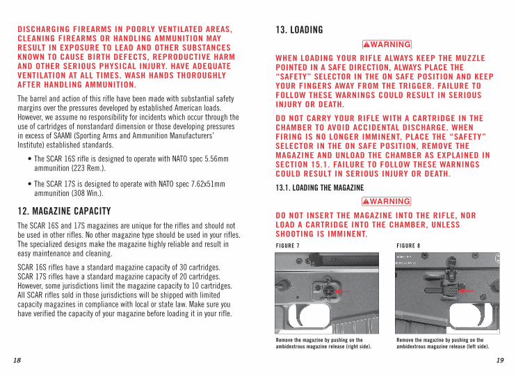
FigUre 7
remove the magazine by pushing on the ambidextrous magazine release (right side).
FigUre 8
remove the magazine by pushing on the ambidextrous magazine release (left side).

20 21
FiNgerS AWAy FroM tHe trigger. FAilUre to FolloW tHeSe WArNiNgS CoUld reSUlt iN SerioUS iNjUry or deAtH.
1. Make sure the “safety” selector is in the on safe position as explained in Section 9 and the muzzle is pointed in a safe direction.
2. Lock the bolt in the open or rear position by pulling the charging handle all the way to the rear and pressing inward on the bottom portion of the bolt release (Figure 6, page 17).
3. Insert the loaded magazine into the magazine well until it locks in place.
4. If shooting is imminent, a cartridge can now be moved from the magazine to the chamber by pulling back fully on the charging handle and releasing it, or pressing on the top of the bolt release, and allowing the bolt to move forward into battery. If the bolt is not allowed to close in this manner, there is a possibility that it will not close completely, preventing the rifle from firing.
5. Push forward on the charging handle, using it as a forward assist to ensure the bolt is locked and the round is properly chambered.
tHe riFle iS NoW reAdy to Fire by MoviNg tHe “SAFety” SeleCtor to tHe oFF SAFe poSitioN ANd pUlliNg tHe trigger.
14. FiriNg
Never CHAMber A CArtridge or Move tHe “SAFety” SeleCtor FroM tHe oN SAFe poSitioN UNleSS SHootiNg iS iMMiNeNt. AlWAyS keep tHe MUZZle poiNted iN A SAFe direCtioN. FAilUre to FolloW tHeSe WArNiNgS CoUld reSUlt iN SerioUS iNjUry or deAtH.
1. Make sure the “safety” selector is in the on safe position as explained in Section 9 and the muzzle is pointed in a safe direction.
2. Press the ambidextrous magazine release located just in front of the trigger guard. The right magazine release is shown in Figure 7 (page 19), the left magazine release is shown in Figure 8 (page 19). Remove the magazine with your free hand.
3. Pull the bolt completely rearward, lock the bolt in the open position as explained in Section 10.2., and inspect the chamber to make sure it is empty. Return the bolt to the forward, closed position.
4. Load the cartridges into the magazine by placing a cartridge on the top of the retaining lips and, with your thumb, pushing it straight down against the force of the follower spring until it locks into position under the retaining lips (Figure 9). Continue to load the magazine in this manner.
Care should be exercised in positioning each cartridge so that its base is flush with the rear of the magazine. If the nose of a cartridge protrudes beyond the front of the magazine, it could cause feeding problems or interfere with the insertion of the magazine into the rifle.
13.2. loAdiNg tHe CHAMber FroM tHe MAgAZiNe
WHeN loAdiNg yoUr riFle AlWAyS keep tHe MUZZle poiNted iN A SAFe direCtioN ANd plACe tHe “SAFety” SeleCtor iN tHe oN SAFe poSitioN. keep yoUr
FigUre 9
press each cartridge straight down into the magazine until it is retained by the magazine lips, and firmly seating it to the rear.

22 23
4. When ready to fire, move the “safety” selector into the off safe position, take aim and squeeze the trigger.
dUriNg exteNded SHootiNg SeSSioNS or rApid FiriNg tHe 3, 6 ANd 9 0’CloCk ACCeSSory rAilS CAN beCoMe extreMely Hot. WeAr gloveS to preveNt bUrNiNg yoUr HANdS. FAilUre to FolloW tHiS WArNiNg CoUld reSUlt iN SerioUS iNjUry.
5. After a cartridge has fired, the bolt and charging handle automatically move rearward, eject the empty case, then return forward, chambering a loaded cartridge from the magazine. See Figure 11 for correct hand placement to avoid injury from the moving charging handle.
Because fired cases are ejected to the right side, bystanders should not stand to the right of the shooter.
6. This operation is repeated each time you pull the trigger until the last cartridge from the magazine has been fired. If shooting is no longer imminent, immediately place the “safety” selector in the on safe position. See “Unloading” in Section 15 for more information.
14.1 FiriNg proCedUreS
1. Make sure the “safety” selector is in the on safe position as explained in Section 9 and the muzzle is pointed in a safe direction.
2. IMPORTANT: Before firing the rifle, make sure the gas regulator is in the 12 o’clock position (Figure 10). This is the proper position for normal firing conditions. If the gas regulator is not in the 12 o’clock position the rifle may not function correctly.
3. Load a cartridge into the chamber as explained previously. With a cartridge in the chamber, you need only to move the “safety” selector to the off safe position to make the rifle ready for firing. Do not move the “safety” selector to the off safe position unless shooting is imminent.
tHe riFle iS NoW reAdy to Fire by MoviNg tHe “SAFety” SeleCtor to tHe oFF SAFe poSitioN ANd pUlliNg tHe trigger.
tHe SCAr 16S riFle HAS A reCiproCAtiNg CHArgiNg HANdle. CAre SHoUld be tAkeN to eNSUre proper SUpport HANd plACeMeNt to preveNt tHe CHArgiNg HANdle FroM StrikiNg yoUr HANd. tHe CorreCt HANd plACeMeNt iS SHoWN iN FigUre 11. tHe iNCorreCt HANd plACeMeNt iS SHoWN iN FigUre 12. FAilUre to FolloW tHiS WArNiNg CoUld reSUlt iN SerioUS iNjUry.
FigUre 12
incorrect hand placement
FigUre 11
Correct hand placement
FigUre 10
the gas regulator shown in the correct, 12 o’clock position

24 25
3. Pull rearward on the charging handle to completely eject the cartridge case.
4. Inspect, and if necessary, clean the rifle as outlined in Section 20.
15. UNloAdiNg
WHeN UNloAdiNg yoUr riFle AlWAyS plACe tHe “SAFety” SeleCtor iN tHe oN SAFe poSitioN ANd reMove tHe MAgAZiNe. keep tHe MUZZle poiNted iN A SAFe direCtioN ANd yoUr FiNgerS AWAy FroM tHe trigger. loCk tHe bolt iN tHe opeN poSitioN AS explAiNed iN SeCtioN 10.2. iNSpeCt tHe CHAMber ANd bArrel CAreFUlly to be SUre All live CArtridgeS Are CleAred FroM tHe FireArM. FAilUre to FolloW tHeSe WArNiNgS CoUld reSUlt iN SerioUS iNjUry or deAtH.
15.1. UNloAdiNg tHe riFle
1. Make sure the “safety” selector is in the on safe position as explained in Section 9 and the muzzle is pointed in a safe direction.
2. Press the ambidextrous magazine release and reMove the magazine.
3. Extract and eject any live cartridge that may be in the chamber by pulling rearward on the charging handle to draw the bolt to its rearmost, open position and pressing the bolt lock as explained in Section 10.2.
Please note that the bolt will not automatically lock in the rearward position when the magazine is removed or when a loaded magazine is present. As a good safety practice, hold the bolt open and visually inspect the chamber to be absolutely certain a live cartridge is not present (Figure 13, page 26).
7. After the last cartridge is fired, the bolt will lock in the rearward position. If you wish to continue shooting, you can reload the rifle by removing the empty magazine and inserting a loaded magazine as described previously. After reloading the magazine, if shooting is imminent, you can chamber a cartridge and resume firing by pulling the charging handle fully rearward and releasing it, or by pressing the bolt release (Figure 5) and pushing forward on the charging handle, using it as a forward assist to ensure the bolt is locked and the round is properly chambered.
If your rifle is to be put away and stored, do not reload the rifle or magazine. The chamber and magazine must remain empty when storing your rifle.
AFter FiriNg, or WHeN SHootiNg iS No loNger iMMiNeNt, iMMediAtely plACe tHe “SAFety” SeleCtor iN tHe oN SAFe poSitioN. FAilUre to FolloW tHeSe WArNiNgS CoUld reSUlt iN SerioUS iNjUry or deAtH.
eveN WitH tHe bolt opeN AFter SHootiNg, do Not ASSUMe tHe riFle iS UNloAded. AlWAyS iNSpeCt tHe CHAMber, bArrel, Feed MeCHANiSM ANd MAgAZiNe to be CertAiN tHe riFle iS CoMpletely UNloAded. FAilUre to FolloW tHeSe WArNiNgS CoUld reSUlt iN SerioUS iNjUry or deAtH.
14.2. MAlFUNCtioNS
If your rifle suffers a malfunction, such as the failure to fully eject a fired cartridge case, perform the following operation to clear the rifle.
1. Immediately place the “safety” selector is in the on safe position as explained in Section 9 and keep the muzzle is pointed in a safe direction.
2. Remove the magazine from the rifle as explained in Section 13.1.

26 27
poiNted iN A SAFe direCtioN. FAilUre to FolloW tHeSe WArNiNgS CoUld reSUlt iN SerioUS iNjUry or deAtH.
The SCAR buttstock module has side folding capabilities and is adjustable for length of pull (LOP) and cheek rest height to allow the stock to be adjusted to fit the size of the operator.
17.1. FoldiNg tHe bUttStoCk ModUle
1. Press the buttstock lock to release it from the backplate (Figure 14).
2. Fold the buttstock to the right (Figure 15).
4. With the magazine removed and the chamber empty, close the bolt. Make certain the “safety” selector is in the on safe position and properly store your rifle.
15.2. UNloAdiNg tHe MAgAZiNe
Unload the magazine by pushing the cartridges, one at a time, forward and out of the magazine.
16. MoUNtiNg ACCeSSorieS
beFore MoUNtiNg A SCope, SigHt or otHer ACCeSSorieS oN yoUr riFle, plACe tHe “SAFety” SeleCtor iN tHe oN SAFe poSitioN. reMove tHe MAgAZiNe, loCk opeN tHe bolt AS explAiNed iN SeCtioN 10.2. ANd MAke CertAiN tHe CHAMber iS CoMpletely UNloAded. keep tHe MUZZle poiNted iN A SAFe direCtioN. FAilUre to FolloW tHeSe WArNiNgS CoUld reSUlt iN SerioUS iNjUry or deAtH.
The SCAR receiver is machined with a MIL-STD 1913 rail for optics mounting on top, along with three accessory MIL-STD 1913 rails in the fore-end area positioned at 3, 6 and 9 o’clock.
17. bUttStoCk ModUle
beFore perForMiNg StoCk AdjUStMeNt proCedUreS, plACe tHe “SAFety” SeleCtor iN tHe oN SAFe poSitioN. reMove tHe MAgAZiNe, loCk opeN tHe bolt AS explAiNed iN SeCtioN 10.2. ANd MAke CertAiN tHe CHAMber iS CoMpletely UNloAded. keep tHe MUZZle
FigUre 16
ensure the buttstock is locked.
FigUre 17
pull down and away to unlock the buttstock.
FigUre 14
press the buttstock lock.
FigUre 15
Fold the buttstock.
FigUre 13
verify the chamber is unloaded.

28
3. Lock the buttstock by applying slight pressure to the buttstock, ensuring the buttstock locking notch engages the shell deflector (Figure 16, page 27).
17.2. UNFoldiNg tHe bUttStoCk ModUle
1. Firmly grasp buttstock and unlock it from the shell deflector by pulling down and away from the receiver (Figure 17, page 27).
2. Fold the buttstock to the left with enough force to ensure a positive lock into the backplate.
3. Inspect buttstock to ensure a positive lock.
17.3. AdjUStiNg leNgtH oF pUll
To adjust the length of pull (LOP), press the LOP adjustment lock (Figure 18) and push or pull buttstock module to change LOP as desired (Figure 19).
Adjustments are numbered 1 through 6. Each adjustment is equal to .50" for a total of 2.50" of LOP adjustment. After adjusting LOP, check to see that the LOP adjustment lock is fully engaged by pulling or pushing on the rear of the stock.
17.4. AdjUStiNg tHe CHeek reSt HeigHt
To adjust the cheek rest height, press the cheek rest button (Figure 20) and push or pull the cheek rest down or up to the desired position (Figure 21). Raising the cheek rest will provide an additional 0.51" of comb height. After adjusting the cheek rest to the desired setting, check to see that the cheek rest button is fully engaged by pulling up or pushing down on the cheek rest.
18. SigHtS
beFore AdjUStiNg tHe SigHtS, plACe tHe “SAFety” SeleCtor iN tHe oN SAFe poSitioN. reMove tHe MAgAZiNe, loCk opeN tHe bolt AS explAiNed iN SeCtioN 10.2. ANd MAke CertAiN tHe CHAMber iS CoMpletely UNloAded. keep tHe MUZZle poiNted iN A SAFe direCtioN. FAilUre to FolloW tHeSe WArNiNgS CoUld reSUlt iN SerioUS iNjUry or deAtH.
18.1. explANAtioN oF tHe SCAr 16S SigHt SySteM
SCAR rifles include rear and front iron sights that are fully adjustable for both windage and elevation.
FigUre 20
press and hold the cheek rest button.
FigUre 21
Move the cheek rest to the desired height.
FigUre 18
press and hold the lop Adjustment button.
FigUre 19
Move the buttstock to the desired length.
29

30 31
These mechanical settings will allow you to obtain a 25m/300m zero.
it iS reCoMMeNded FroM tHiS poiNt tHAt yoU USe tHe FroNt SigHt to obtAiN yoUr iNitiAl Zero. tHe reAr SigHt elevAtioN AdjUStMeNt iS USed oNly For AdditioNAl tArgetiNg diStANCeS.
1. Flip up the rear sight by grasping the rear sight housing and pulling up and towards the muzzle until you feel it lock into place (Figure 24).
The rear sight assembly is adjusted by hand. It consists of a MIL-STD-1913 rail mount, two sight apertures, an elevation drum, and two windage knobs, one on each side of the sight (Figure 22).
The front sight assembly can be adjusted with a TORX® T25 wrench, and a M16/AR15 A2 sight tool. The front sight assembly consists of a front sight housing with index line, a front sight post, a front sight post detent, a windage screw with arrow, a windage screw detent, and a front locking cam (Figure 23, page 31).
18.2. ZeroiNg
Your sights are pre-set to a mechanical zero from the factory, these settings are as follows:
• Front sight: The base of the front sight post is flush with the opening of the front sight housing and the front sight housing index line is centered on the center gas block index line.
• Rear sight: The rear sight housing index line and the rear sight post index line should be aligned and elevation drum set to 3.
FigUre 24
Flip the rear sight into position until it locks in place.
FigUre 25
push the front sight lock forward and flip back into position until it locks in place.
FigUre 23
Front Sight Nomenclature
Front Sight post
Front Sight Housing index lines
gas block index line
Front Sight Housing
Front Sight locking Cam
Front Sight Windage knob
FigUre 22
rear Sight Nomenclature
Sight Aperture
elevation drum
Sight Aperture Housing
rear Sight Housing index line
left Windage knob
right Windage knob
rail Mount
rear Sight post index line
left Windage knob
rear Sight Housing

32 33
• Rotate the front sight post counterclockwise to move the point of impact down.
7. Adjust windage by turning the windage screw on the left side of the front sight with a TORX® T25 wrench. Each click is equal to 1 MOA.
• Rotating the windage screw rearward or clockwise (towards you) will move the point of impact to the right;
• Rotating the windage screw forward or counterclockwise (away from you) will move the point of impact to the left.
19. diSASSeMbly
beFore perForMiNg diSASSeMbly proCedUreS, plACe tHe “SAFety” SeleCtor iN tHe oN SAFe poSitioN. reMove tHe MAgAZiNe, loCk opeN tHe bolt AS explAiNed iN SeCtioN 10.2. ANd MAke CertAiN tHe CHAMber iS CoMpletely UNloAded. keep tHe MUZZle poiNted iN A SAFe direCtioN. FAilUre to FolloW tHeSe WArNiNgS CoUld reSUlt iN SerioUS iNjUry or deAtH.
WeAr eye proteCtioN WHeN diSASSeMbliNg ANd CleANiNg yoUr riFle to preveNt SpriNgS, SpriNg-loAded pArtS, SolveNtS or otHer AgeNtS FroM CoNtACtiNg yoUr eyeS, reSUltiNg iN iNjUry.
Notice! tHiS riFle iS A SpeCiAliZed, FiNely-Fitted MeCHANiSM. yoU MAy dAMAge it beyoNd repAir or loSe SMAll pArtS by AtteMptiNg to diSASSeMble tHe iNNer MeCHANiSM ASSeMblieS. iF FUrtHer diSASSeMbly For ServiCe or CleANiNg iS reqUired, SeNd it to tHe FNH USA ServiCe FACility iN ArNold, MiSSoUri.
2. Flip up the front sight by pushing the front sight lock towards the muzzle and unlocking the sight. Pull housing upwards and to the rear until you feel it lock into position (Figure 25, page 31).
3. The rear sight has two sight apertures that flip up and down.
• The large aperture is used for close quarters engagement, low light conditions or when a larger field of view is required.
• The small aperture is used for zeroing and for normal firing conditions.
4. The elevation drum has numbers from 2-6 to reflect the five different elevation settings corresponding to target distance in hundreds of meters. #2 indicates the lowest position of the sight aperture. Each click is equal to 1.5 MOA.
• Rotate the elevation drum counterclockwise to move the point of impact up.
• Rotate the elevation drum clockwise to move the point of impact down.
5. The windage knobs are numbered from 1-6 and engraved with the letter “R” for right to reflect the direction of point of impact shift. Each click is equal to 1 MOA.
• Rotating the windage knobs rearward (towards you) will move the point of impact to the left.
• Rotating the windage knobs forward (away from you) will move the point of impact to the right.
6. Use an M16/AR15 A2 sight tool to turn the front sight post and adjust elevation. Each click is equal to 1.5 MOA.
• Rotate the front sight post clockwise (in the direction of the arrow) to move the point of impact up.

35
2. Push in on the takedown pin from the left side (Figure 26) and pull it out to the right until it stops (Figure 27).
IMPORTANT: The takedown pin is captive and cannot be removed completely from the trigger module.
3. Push the trigger module forward, releasing it from the from the backplate (Figure 28).
4. Pull down to remove the trigger module from the receiver (Figure 29).
19.2. reMovAl oF tHe bUttStoCk ModUle
1. Remove the magazine and make certain the rifle is completely unloaded and the “safety” selector is in the on safe position as explained in Section 9.
2. Remove the trigger module as explained in Section 19.1.
3. Push the buttstock module downward and off of the receiver assembly backplate (Figure 30).
19.3. reMovAl oF tHe MoviNg pArtS ASSeMbly
1. Remove the magazine and make certain the rifle is completely unloaded and the “safety” selector is in the on safe position as explained in Section 9.
2. Remove the trigger module as explained in Section 19.1. and the Buttstock Module as explained in Section 19.2.
Notice! tHe FolloWiNg diSASSeMbly proCedUreS Are deSigNed to be perForMed WitH FiNger preSSUre oNly ANd No toolS Are to be USed. iF yoU CANNot CoMplete tHe diSASSeMbly proCedUreS deSCribed WitHoUt tHe USe oF toolS Stop ANd CoNtACt FNH USA ServiCe FACility iN ArNold, MiSSoUri.
19.1. reMovAl oF tHe trigger ModUle
1. Remove the magazine and make certain the rifle is completely unloaded and the “safety” selector is in the on safe position as explained in Section 9.
34
FigUre 30
push the buttstock module off of the receiver assembly.
FigUre 26
push in on the takedown pin from the left side.
FigUre 27
pull the takedown pin to the right until it stops.
FigUre 28
push the trigger module forward.
FigUre 29
pull the trigger module down to remove it.

36 37
4. Remove moving parts assembly as explained in Section 19.3.
5. Push the firing pin retaining pin out of the bolt carrier from right to left by using the small end of the charging handle (Figure 33).
6. Remove the firing pin from the rear of the bolt carrier (Figure 34).
7. Remove the bolt cam pin from the left side of the bolt (Figure 35).
8. Remove the bolt from the front of the bolt carrier (Figure 36).
3. Pull the charging handle rearward and apply downward pressure to the guide rod retaining plate (Figure 31). Then pull the charging handle all the way to the rear.
4. With the moving parts assembly to the rear, pull out on the charging handle and remove it from the assembly (Figure 32).
5. Remove the return spring assembly by pulling it out towards the rear.
6. With the charging handle and return spring assembly removed, the entire moving parts assembly can be removed from the rear of the receiver by placing your hand at the rear of the receiver and raising the muzzle, allowing the moving parts assembly to slide out into your hand.
19.4. diSASSeMbly oF tHe MoviNg pArtS ASSeMbly
1. Remove the magazine and make certain the rifle is completely unloaded and the “safety” selector is in the on safe position as explained in Section 9.
2. Remove the trigger module as explained in Section 19.1.
3. Remove the buttstock module as explained in Section 19.2.
remove the bolt.
FigUre 36FigUre 35
remove the bolt cam pin.
FigUre 32
remove the charging handle.
FigUre 34
remove the firing pin.
FigUre 33
Use the charging handle to remove the firing pin retaining pin.
FigUre 31
pull down on the retaining plate and pull back on the charging handle.

38 39
19.5. reMovAl oF tHe gAS regUlAtor ANd gAS piStoN
1. Remove the magazine and make certain the rifle is completely unloaded and the “safety” selector is in the on safe position as explained in Section 9.
2. Remove the trigger module as explained in Section 19.1.
3. Remove the buttstock module as explained in Section 19.2.
4. Remove moving parts assembly as explained in Section 19.3.
5. Ensure the front sight is in the up position.
6. Turn the gas regulator to the 12 o’clock position.
7. Use the small end of the charging handle to push in on the gas regulator detent and turn the gas regulator clockwise to the 4 o’clock position (Figure 37).
8. Remove the gas regulator towards the front (Figure 38).
9. Place the muzzle down on a soft surface. Lower a cleaning rod (with a 5.56mm or .223 bronze cleaning brush attached) down through the receiver until it comes in contact with the gas piston. (The gas piston is visible through the slots in the receiver.)
10. Softly tap the piston and it will come out towards the front.
Notice! do Not tAke yoUr FireArM’S ACtioN ApArt beyoNd WHAt iS explAiNed iN tHiS oWNer’S MANUAl. tHiS iS A SpeCiAliZed, FiNely Fitted MeCHANiSM; ANy AtteMpt to diSASSeMble tHe iNNer MeCHANiSM MAy dAMAge it For liFe. it iS UNNeCeSSAry, ANd MAy do dAMAge to tHe iNNer MeCHANiSM to diSASSeMble it For roUtiNe CleANiNg ANd oiliNg. oF CoUrSe, MiSFortUNeS (SUCH AS droppiNg yoUr FireArM iN WAter) reqUire AppropriAte AtteNtioN, ANd iN SUCH CirCUMStANCeS We reCoMMeNd yoU iMMediAtely tAke yoUr FireArM to A qUAliFied gUNSMitH.
20. CleANiNg ANd lUbriCAtioN
beFore perForMiNg CleANiNg proCedUreS, plACe tHe “SAFety” SeleCtor iN tHe oN SAFe poSitioN. reMove tHe MAgAZiNe, loCk opeN tHe bolt AS explAiNed iN SeCtioN 10.2. ANd MAke CertAiN tHe CHAMber iS CoMpletely UNloAded. keep tHe MUZZle poiNted iN A SAFe direCtioN. FAilUre to FolloW tHeSe WArNiNgS CoUld reSUlt iN SerioUS iNjUry or deAtH.
WeAr eye proteCtioN WHeN diSASSeMbliNg ANd CleANiNg yoUr riFle to preveNt SpriNgS, SpriNg-loAded pArtS, SolveNtS or otHer AgeNtS FroM CoNtACtiNg yoUr eyeS, reSUltiNg iN iNjUry.
keep All AMMUNitioN AWAy FroM tHe CleANiNg AreA. Never teSt tHe MeCHANiCAl FUNCtioN oF yoUr riFle WitH live AMMUNitioN. FAilUre to FolloW tHeSe WArNiNgS CoUld reSUlt iN SerioUS iNjUry or deAtH.
FigUre 37
push the detent and rotate the gas regulator.
FigUre 38
remove the gas regulator.

40 41
If necessary, clean the chamber and locking lugs using a Mil-Standard M16 style chamber brush. Properly apply CLP to the brush and insert it into the chamber. Rotate the brush in a clockwise direction several times and remove.
4. After all fouling has been removed, the chamber and bore should be wiped dry. When the bore is dry, pass a patch that is lightly lubricated with CLP through it for preservation.
5. Inspect the barrel and chamber to be certain no patches have inadvertently been left in them. Remove any that remain.
6. Use a small brush or rag to remove dirt and foreign matter from inside the receiver and other parts of the action. Lightly lubricate all moving parts with CLP.
7. Use a small brush and CLP to clean the bolt and bolt carrier. Wipe dry and reassemble.
8. Use a cleaning cloth to clean the gas piston. It may be necessary to use a bronze bristle brush to remove carbon build up from the piston.
Notice! do Not Apply lUbriCANt to tHe gAS piStoN, gAS regUlAtor or gAS bloCk, tHeSe CoMpoNeNtS Are Not to be lUbriCAted iN ANy WAy. USiNg lUbriCAtioN iN tHe gAS SySteM CoUld dAMAge yoUr riFle.
9. Inspect the gas ports in the gas regulator to ensure they are free of debris and carbon build-up. If the ports are fouled, it may be necessary to use a dental pic to remove carbon build up (Figure 39).
20.1. CleANiNg proCedUreS
Your SCAR 16S will function better, more reliably and be more accurate over a longer period of time if it is properly maintained and kept clean. Clean your firearm after every day of shooting, and more often if it becomes excessively dirty during your shooting session. A minimum cleaning includes wiping down the firearm and lubricating key parts. Regular maintenance will also include cleaning the barrel and gas system.
If you encounter a function problem be sure to give your firearm a thorough cleaning to see if it solves the problem before seeking the services of the FNH USA Service Facility in Arnold, Missouri, or a qualified gunsmith.
1. Remove the magazine and make certain the rifle is completely unloaded and the “safety” selector is in the on safe position as explained in Section 9.
2. Disassemble the rifle as explained in Section 19.
3. Inspect the chamber and bore for powder fouling. A normal amount of powder residue can be expected and is not serious. It can usually be removed with a patch and CLP (cleaner, lubricant and protectant).
Use a rifle cleaning rod with a brass jag and patch large enough for a snug fit in the bore. Apply a small amount of CLP and insert the rod and patch into the barrel from the breech end and run it back and forth several times. Care should be exercised to ensure that the cleaning rod does not strike the crown of the muzzle, as damage to this area can adversely affect the accuracy of the rifle.
If, or when, fouling should become heavy, it can be removed with a bronze bore brush. Dip or spray the brush with CLP and scrub the chamber and bore until the fouling is removed. To prevent bronze bristles from breaking off, the brush should be pushed completely through the barrel before being withdrawn.
Notice! do Not USe A StAiNleSS Steel brUSH to CleAN tHe bore. it CoUld dAMAge tHe CHroMe plAtiNg.
FigUre 39
Use a dental pic to remove carbon build up from the gas ports in the gas regulator.

42 43
Notice! do Not USe too MUCH lUbriCANt. exCeSSive lUbriCAtioN CoUld iNterFere WitH tHe FUNCtioN oF yoUr riFle.
20.3. CleANiNg tHe MAgAZiNe
WeAr eye proteCtioN WHeN CleANiNg tHe MAgAZiNe to preveNt SolveNt, debriS or otHer AgeNtS FroM CoNtACtiNg yoUr eyeS, reSUltiNg iN iNjUry.
We do not recommend disassembling the magazine. Frequently inspect magazines to determine the need for cleaning as lubricant and dirt will gradually collect in the mechanism.
1. Clean the magazine by spraying it with a polymer-safe aerosol gun cleaner that will not adversely affect the follower or corrode the metal components. Spray the magazine with this solvent, both inside and out, to loosen debris.
2. Drain the solvent and residue from inside the magazine.
3. Use compressed air to dry the magazine or allow it to air dry and lightly oil.
21. ASSeMbly21.1. iNStAllAtioN oF tHe gAS piStoN ANd gAS regUlAtor
Notice! do Not Apply lUbriCANt to tHe gAS piStoN, gAS regUlAtor or gAS bloCk, tHeSe CoMpoNeNtS Are Not to be lUbriCAted iN ANy WAy. USiNg lUbriCAtioN iN tHe gAS SySteM CoUld dAMAge yoUr riFle.
10. Wipe all exposed metal surfaces with a lightly oiled cloth making certain that all finger marks are removed. Finger marks provide a place where moisture can accumulate. The metal of the firearm should receive a light film of oil any time it has been exposed to weather or handling.
20.2. CleANiNg tHe trigger ModUle
The trigger module has been adjusted at the factory to provide a short, crisp pull consistent with safety and reliability. It is recommended that no attempt be made to change the weight of pull of the trigger.
Notice! do Not Alter or AtteMpt to diSASSeMble ANy pArt oF tHe trigger ModUle.
If any service of the trigger module or bolt becomes necessary, send the entire rifle to the FNH USA Service Center in Arnold, Missouri (Section 23) or contact your departmental armorer.
1. Remove the magazine and make certain the rifle is completely unloaded and the “safety” selector is in the on safe position as in Section 9.
2. Remove the trigger module as explained in Section 19.1.
3. After removing the trigger module, place the “safety” selector in the off safe position.
4. Release the hammer by placing your thumb over the hammer and pulling the trigger. Be sure to keep tension on the hammer and lower it slowly to the forward resting position.
Notice! Never AlloW tHe HAMMer to SlAM ForWArd, tHiS MAy dAMAge tHe trigger ModUle.
5. Perform any cleaning of the parts and receiver cavity as necessary. We suggest cleaning the trigger group with a polymer-safe aerosol gun cleaner. Allow it to dry and then very lightly lubricate the trigger and hammer contact points.

1. Ensure that the notches in the gas rings of the piston are not aligned (Figure 40).
2. Insert the gas piston into the gas block with the gas rings towards the muzzle.
3. Install the gas regulator, using the small end of the charging handle to push in on the gas regulator detent, and rotate counterclockwise to the 12 o’clock position (Figure 41).
21.2. ASSeMbliNg tHe MoviNg pArtS ASSeMbly
1. Insert the bolt into the front of the bolt carrier, ensure that the extractor is positioned on the right side (Figure 42).
2. Insert the bolt cam pin, ensuring the tab is horizontal (Figure 43, page 45).
3. Insert firing pin from the rear.
4. Insert the firing pin retaining pin until firmly seated. When firmly seated the firing pin retaining pin will not be completely flush with the bolt carrier.
Notice! do Not USe extreMe ForCe oN tHe FiriNg piN retAiNiNg piN, it iS Not deSigNed to Fit FlUSH iNto tHe bolt CArrier. ApplyiNg extreMe ForCe to tHe FiriNg piN retAiNiNg piN CoUld reSUlt iN perMANeNt dAMAge.
21.3. iNStAllAtioN oF tHe MoviNg pArtS ASSeMbly
1. Install the return spring assembly into the moving parts assembly. Make certain that the narrow end of the guide rod retaining plate is up.
2. Ensure the upper portion of the bolt carrier is aligned with the bolt carrier guide rails inside the receiver frame and the bolt is fully forward in the bolt carrier (Figure 44).
44 45
FigUre 44
install the bolt carrier into the receiver frame.
FigUre 45
insert the charging handle.
FigUre 42
insert the bolt into the carrier.
FigUre 43
insert the bolt cam pin through the slot and into the bolt.
FigUre 41
install the gas regulator by turning counterclockwise to the 12 o’clock position.
FigUre 40
ensure the gas rings are not aligned as shown in the photo on the left.
incorrect Correct

46 47
3. Slide the moving parts assembly back into the receiver until the charging handle slot on the bolt carrier is aligned with the charging handle slot in the receiver frame.
4. Insert the charging handle into the left or right side of the receiver (Figure 45, page 45). (Generally into the left side for right-handed operators and into the right side for left-handed operators.)
5. Using the charging handle, slide the moving parts assembly all the way forward in the receiver. You may need to apply downward pressure on top of the guide rod retaining plate to clear the backplate in order to slide the moving parts assembly all the way forward.
IMPORTANT: Be sure that the guide rod retaining plate is fully seated into the backplate or it will prevent the buttstock from sliding into place.
21.4. iNStAllAtioN oF tHe bUttStoCk ModUle
1. Install the buttstock module by pressing in on the retaining plate and sliding the buttstock module on the backplate until seated (Figure 46).
21.5. iNStAllAtioN oF tHe trigger ModUle
1. Ensure that the takedown pin is pushed completely to the right of the trigger module (Figure 47).
2. Ensure that the hammer is cocked prior to re-installing the trigger module. If the hammer is not cocked (Figure 48), press it down into the cocked position for assembly (Figure 49).
3. Place the trigger module into position, ensuring the rear extrusion engages the notch on the backplate at a slight angle (Figure 50).
4. Carefully rotate the trigger module into the receiver frame, pushing it to the rear (Figure 51).
FigUre 48
the hammer shown in the decocked position.
FigUre 49
Cock the hammer by rotating to the rear.
FigUre 50
insert the trigger module rear first into the receiver.
FigUre 51
raise the front of the trigger module into the receiver and push it rearward.
FigUre 46
Apply finger pressure to the retaining plate and slide the buttstock module into place.
FigUre 47
Move the takedown pin to the right side of the housing.

48 49
5. Ensure the trigger module is fully seated to the rear before pushing the takedown pin to the left and securing the trigger module to the receiver assembly (Figure 52).
Your firearm is now fully assembled. Immediately confirm that the “safety” selector is in the on safe position. Take time to wipe down and clean all external surfaces as explained under “Cleaning and Maintenance Suggestions.” Perform the function check as explained in Section 21.6.
21.6. FUNCtioN CHeCk
With the rifle assembled, perform a function check to ensure proper re-assembly.
1. Operate the charging handle, making certain the bolt assembly moves freely.
2. Operate the “safety” selector, making certain that the “safety” selector moves between on safe and off safe freely.
3. Place the “safety” selector in the on safe position and properly store the rifle.
22. tAkiNg CAre oF tHe riFle
Notice! yoUr riFle SHoUld be iNSpeCted every 5000 roUNdS ANd/or oNCe A yeAr by A qUAliFied gUNSMitH or tHe FNH USA prodUCt ServiCe CeNter beCAUSe dAMAge, WeAr ANd CorroSioN Are Not AlWAyS viSible FroM tHe oUtSide. lAW eNForCeMeNt ANd MilitAry perSoNNel SHoUld CoNtACt tHeir depArtMeNtAl ArMorer WHo Will iNSpeCt tHe riFle oN A yeArly bASiS.
Notice! iF tHe operAtioN oF tHe riFle SeeMS AbNorMAl, report it to yoUr deAler or depArtMeNtAl ArMorer iMMediAtely.
• Always keep the rifle in immaculate condition and good working order.
• Always clean and lubricate the rifle after use.
• Regularly inspect the rifle, its parts and accessories.
23. ServiCe poliCyIf you have any questions about this owner’s manual or other FNH USA products, contact:
FNH USA, LLC Commercial and Law Enforcement Sales Phone (703) 288-1292, extension 122 Or visit us online at www.fnhusa.com
IF YOU DO NOT UNDERSTAND THE INSTRUCTIONS FOR OPERATING YOUR FNH USA FIREARM, IT IS YOUR RESPONSIBILITY TO CONTACT THE FNH USA PRODUCT SERVICE CENTER AT (703) 208-1292 BEFORE USING THE FIREARM.
This owner’s manual should always accompany this rifle and be transferred with it upon any change of ownership.
FNH USA products are serviced by the FNH USA Product Service Center in Arnold, Missouri.
Please call (800) 635-1321 to discuss any product repair requirements.
Shipping Address: FNH USA Product Service Center 3005 Arnold Tenbrook Road Arnold, MO 63010-4728
FigUre 52
press the takedown pin into position.

5150
24. WArrANty, ServiCe ANd teCHNiCAl qUeStioNSFor technical questions about service or your firearm contact:
FNH USA Customer Support Phone: (703) 288-1292
If your FNH USA product should require service or repair contact the FNH USA Product Service Center in Arnold, Missouri. Law enforcement and military users should contact their department or unit armorer.
FNH USA Product Service Center 3005 Arnold Tenbrook Road Arnold, MO 63010-4728 Phone: (800) 635-1321
When returning your FNH USA firearm for servicing you must do the following:
1. Be sure it is completely unloaded.
2. Remove the scope, optics or accessories.
3. Package it securely in a cardboard container.
4. Enclose the service/repair form available at www.fnhusa.com or a letter that clearly describes the trouble experienced, the ammunition used and the repairs desired. Also include your name and a daytime phone number where you can be reached.
5. If convenient, send a copy of the service/repair form or letter to us separately.
6. Never return ammunition with your firearm. It is against postal and most commerce regulations.
25. teCHNiCAl SpeCiFiCAtioNSCaliber : 16S: 5.56mm NATO (223 Rem.)
17S: 7.62x51mm NATO (308 Win.)
Type of fire : Semi-automatic
Trigger pull : 6.25 lbs. (+/- 1.5 lbs.)
Weight : 16S: 7.25 lbs.
17S: 8.0 lbs.
Length : 16S: 37.5" with stock extended
17S: 38.5" with stock extended
Barrel length : 16.25"
Twist and direction : 16S: 1:7", right-hand
17S: 1:12", right-hand
Magazine capacity : 16S: 10-rounds (limited-capacity magazine) 30-rounds (standard-capacity magazine)
17S: 10-rounds (limited-capacity magazine) 20-rounds (standard-capacity magazine)
All specifications subject to changes without notice.

5352
NoteS NoteS

54
FNH USAfnhusa.com
AO1002/09021