flutter speed limits of subsonic wings
DESCRIPTION
Flutter is a phenomenon resulting from the interaction between aerodynamic and structuraldynamic forces and may lead to a destructive instability. The aerodynamic forces on an oscillating airfoil combination of two independent degrees of freedom have been determined. The problem resolves itself into the solution of certain definite integrals, which have been identified as Theodorsen functions.TRANSCRIPT
Journal of Engineering Volume 18 February 2012 Number 2
163
FLUTTER SPEED LIMITS OF SUBSONIC WINGS Prof. Dr. Muhsin J. Jweeg Ass. Prof. Dr. Shokat Al-Tornachi Eng. Tariq Samir Talib
College of Engineering
Al-Nahrain University College of Engineering
University of Technology College of Engineering
University of Technology BSTRACT
Flutter is a phenomenon resulting from the interaction between aerodynamic and structural dynamic forces and may lead to a destructive instability. The aerodynamic forces on an oscillating airfoil combination of two independent degrees of freedom have been determined. The problem resolves itself into the solution of certain definite integrals, which have been identified as Theodorsen functions. The theory, being based on potential flow and the Kutta condition, is fundamentally equivalent to the conventional wing-section theory relating to the steady case. The mechanism of aerodynamic instability has been analyzed in detail. An exact solution, involving potential flow and the adoption of the Kutta condition, has been analyzed in detail. The solution is of a simple form and is expressed by means of an auxiliary parameter K. The use of finite element modeling technique and unsteady aerodynamic modeling with the V-G method for flutter speed prediction was used on a fixed rectangular and tapered wing to determine the flutter speed boundaries. To build the wing the Ansys 5.4 program was used and the extract values were substituted in the Matlab program which is designed to determine the flutter speed and then predicted the various effects on flutter speed. The program gave us approximately identical results to the results of the referred researches. The following wing design parameters were investigated skin shell thickness, material properties, cross section area for beams, and changing altitude. Results of these calculations indicate that structural mode shape variation plays a significant role in the determination of wing flutter boundary.
الخالصة
هـي الظاهرة الـتي تنتـج مـن التداخـل بيـن القـوى الدينـاهوائيـة ودينـاميكيـة الهيـكل مـما يـؤدي الى حـالـة من ) األرتجـاج(الـرفـرفـة حـريـة باستخدام تحسـب القـوى الدينـاهوائيـة لمقطـع جنـاح مهتـز لـه درجتان مـن ال. عـدم االستقرار وبالتـالي تدميـر وتحـطم الجنـاح
على دالة ويعتمـد أساس هذه . حيـث إن المسألة تحـل باستخـدام التكـامـل المحدد،)(Theodorsen functionنظـريـة ثيـودرسـن، والتي تكـون أساسا مكافئـا لنظـريـة مقـاطع ) Kutta condition(وعلى شرط آوتـا ) potential flow(التدفـق الكامن يتضمن التدفـق و تبني حقيقيالحـل ال. حيث يتم تحليـل اآللية الدينـاهوائيـة الغيـر مستقـرة بشكـل مفصـل.الـة الثـابتـة األجنحـة للحـ
لحسـاب ). K) (auxiliary parametric( يمكن تمثيل الحـل باستخـدام العـامـل المسـاعـد. شـرط آوتـا وتحليـلـه بشكـل مفصـلم تقنيـة العنـاصـر المحـددة و الـنمـوذج الى الجنـاح المستدق والجناح المسـتطيـل حيث تم اسـتخـدحـدود سـرعـة الـرفـرفـة ع
للتنبـؤ بسـرعـة ) V-g) (velocity - damping method(عامل التضاؤل -الدينـاهـوائى الغـير مستقـر مـع طـريقـة السرعـة )MATLAB(تسـتخـدم في بـرنـامـج الـ التي ء الجنـاح والقـيم المسـتخـرجة تم بنـا) ANSYS 5.4(الـرفـرفـة بـاستـخـدام بـرنـامـج
حيـث إن البرنـامـج أعطى نتـائـج .ومنـه التنبـؤ بالمتغيـرات المؤثـرة على سـرعـة الـرفـرفـة. الذي صمم لحسـاب سـرعـة الـرفـرفـةلمتغيرات التصميمية التالية للجناح سمك متغير للغالف ومادة متغيرة تم بحث ا. مطـابقـة تقريبـا إلى نتـائـج البحوث المشـار إليها
اوضحت النتائج بان تغير النسق للهيكل يلعب دورا مهما في حساب سرعة . ومساحة مقطع متغيرة لقطع التقوية وارتفاع متغير .الرفرفة
KEY WORKS: Flutter, V-g Method, Wings.
FLUTTER SPEED LIMITS OF SUBSONIC WINGS Prof. Dr. Muhsin J. Jweeg Ass. Prof. Dr. Shokat Al-Tornachi Eng. Tariq Samir Talib
164
INTRODUCTION
The problem of oscillating airfoils has been an important subject of unsteady aerodynamics because of its close link with flutter analysis. The sustained oscillation is a boundary between convergent and divergent motions. Hence, the speed thus obtained is the critical speed, above which flutter occurs.
(Sadeghi, 2003); developed a code for the computation of three-dimensional aeroelastic problems such as wing flutter. (Bala Krishnan 2003); Investigated the initial mathematical theory of aeroelasticity centered on the canonical problem of the flutter boundary instability endemic to aircraft that limits attainable speed in the subsonic regime. (Massimo Bianchin 2003); Studied a methodology to merge state-space time domain realizations of a complete numerical aeroservoelastic model with flight mechanics equations
UNSTEADY AERODYNAMIC FORCES OF THE TYPICAL SECTION MODEL:-
The unsteady aerodynamic forces are calculated based on the linearized thin - airfoil .In this section, Theodorsen’s approach will be summarized and the flutter analysis will be conducted based on his approach (Theodore Theodorsen 1935).
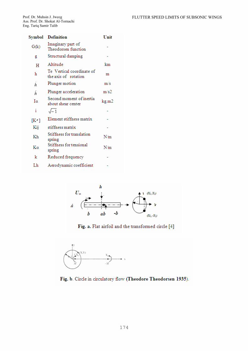
In Theodorsen’s approach, aerodynamic surfaces are modeled by flat plates. Theodorsen assumes that the flat airfoil is oscillating about the shear center (elastic axis) and unsteady flow is composed of two components, (a) non –circulatory flow which can be expressed through the sources and sinks and (b) circulatory flow related to the flat vorticity surface extending from trailing edge to infinity. For each flow component, he obtained the velocity potential and then calculated the pressure using Bernoulli's theory. The Non-circulatory Flow:-
By using Joukoweski’s conformal transformation (Theodore Theodorsen 1935), the airfoil can be mapped onto a circle. The
velocity potential of a source (ε) on a circle ( )11 , yx can be expressed as:
[ ]21
21 )()(
4yyxxLn −+−=
πεϕ
Similarly, the velocity potential is due to a source (2ε) at on circle ( )11, yx and a sink (-2ε) at on circle ( )11, yx − .
⎥⎦
⎤⎢⎣
⎡++−−+−
= 21
21
21
21
)()()()(
2 yyxxyyxxLn
πεϕ
(1)
Since ( 21 xy −= ), the velocity potential is a function of (x) only. The downward displacement of the airfoil can be written as
( )abxhz −+= α Then, up-wash will be
( ) ⎥⎦⎤
⎢⎣⎡
∂∂
+∂∂
−=xZV
tztxwa , =
- ( ) αα Vabxh −⎥⎦⎤
⎢⎣⎡ −+
..
Therefore, the velocity potential due to pitch angle ( )α will be
( ) ( )( ) ( )
212
12
1
21
211
11
2xbVdx
yyxxyyxx
LnVb −=⎥⎦
⎤⎢⎣
⎡
++−−+−−
= ∫− απαϕα
(2) Similarly, velocity potentials due to plunge
motion, (.h ) and angular velocity, (
.α ) are
respectively expressed as:
2.
1..
xbhh
−=ϕ ⎠⎞
⎜⎝⎛ −= axb2
2.
.. αϕα
21 x−
Journal of Engineering Volume 18 February 2012 Number 2
165
The total velocity potential due to non-circulatory flow becomes:
ϕϕϕϕ αα.++=
hNC
22
.2
.2 1)
2(11 xaxbxbhxbV −−+−+−= αα
(3) By Bernoulli theorem, the pressure is obtained as follows:
.222 ϕρϕρϕϕρ −=
∂∂
−=⎟⎠⎞
⎜⎝⎛
∂∂
+∂∂
−=∆tx
Vt
p
(4) And the force (positive downward) and the pitching moment (positive nose-up) about the elastic axis will be expressed as:-
dxbpdxbF NC ∫∫−−
−=∆=1
1
.1
1
2 ϕρ
⎟⎠⎞
⎜⎝⎛ −+−≡
.....2 ααπρ baVhb
(5)
dxaxt
bbdxaxpbMNC )(2)(1
1
1
1
2 −∂∂
−=−∆= ∫∫−−
ϕρ
⎟⎟⎠
⎞⎜⎜⎝
⎛⎟⎠⎞
⎜⎝⎛ +−++≡
..22
.2
...2
81 ααπρ abVhbahVb
(6) The Circulatory Flow:- To satisfy the Kutta condition, Theodorsen employs a bound vortex distribution over the airfoil and a vortex over the airfoil wake. In order to consider wake, assume a bound
vortex ( =∆Γ γ dx ) at ( oX1
), and a shed
vortex ( ∆Γ− ) at ( oX ). Then, the velocity potential due to vortex is
⎥⎦
⎤⎢⎣
⎡−
−−
∆Γ=∆ −−
Γoo XX
YXX
Y/1
tantan2
11
πϕ
⎥⎦
⎤⎢⎣
⎡+++−
−∆Γ−= −
1)/1()/1(
tan2 22
1
YXXXXYXX
oo
oo
π
Define ( ooo xXX 2/1 =+ ), and
(21, xyxX −== )
Then,
12 −+= ooo xxX
11
1/1 2
2−−=
−+= oo
oo
o xxxx
X
The velocity potential can be expressed as
⎥⎥⎦
⎤
⎢⎢⎣
⎡
+−+−
−−∆Γ−=∆ −
Γ 1)1()2()12(1
tan2 22
221
xxxxxx
o
o
πϕ
⎥⎥⎦
⎤
⎢⎢⎣
⎡
−
−−∆Γ−= −
o
o
xxxxx
2
221 11
tan2π
(7) Where
,11 ≤≤− x ∞≤≤ ox1 It is to be noted that the vortex is moving away from the airfoil with velocity of (V). Therefore, by Bernoulli theorem, the pressure due to the vortex is
⎟⎠⎞
⎜⎝⎛
∂∆∂
+∂∆∂
−=∆ ΓΓ
xV
tp ϕϕρ2
Where:
⎥⎥
⎦
⎤
⎢⎢
⎣
⎡
⎥⎥⎦
⎤
⎢⎢⎣
⎡
−−−
∂∂
−=∂∆∂
∆Γ−Γ
o
o
xxxx
xx 111
tan2 221ϕπ
xxx
x
o
o
−−
−=
11
12
2
FLUTTER SPEED LIMITS OF SUBSONIC WINGS Prof. Dr. Muhsin J. Jweeg Ass. Prof. Dr. Shokat Al-Tornachi Eng. Tariq Samir Talib
166
xxx
xx ooo −−
−=
∂∆∂
∆ΓΓ 1
1
122
2ϕπ
The pressure at (X) due to the vortex at ( ox ) is
xxxx
x
xVp
oo
o
−⎥⎥⎦
⎤
⎢⎢⎣
⎡
−−
+−
−∆Γ−=∆ Γ
11
11
12
2 2
2
2
2
πρ
xxxx
xxV
oo
o
−⎥⎥⎦
⎤
⎢⎢⎣
⎡
−−
−∆Γ−=
1112 22
22
πρ
(8)
112 22 −−
+∆Γ−=
o
o
xx
xxV
πρ
The force on the whole airfoil due to a vortex
at )( ox will be
∫−
ΓΓ ∆=∆1
1
dxpbF
∞≤≤∆Γ
−−= o
o
o xx
xVb 1,
12ρ
The total force can be calculated by
integrating with respect to )( ox
∫ ΓΓ ∆= FF
o
o
o dxx
xVb γρ ∫
∞
− −−=
12 1
Similarly,
∫−
ΓΓ ∞≤≤−∆=∆1
1
2 1,)( oxdxaxpbM
∫ ΓΓ ∆= MM
∫∞
⎥⎥⎦
⎤
⎢⎢⎣
⎡
−⎟⎠⎞
⎜⎝⎛ +−
−+
−=1
2
2
121
11
21 dx
x
xa
xx
Vbo
o
o
o γρ
(10) It has to be noted that the force and moment are functions of vortex strength )(γ .By applying Kutta condition at trailing edge the vortex strength can be determined. The total
velocity potential is:
..α
α ϕϕϕϕϕ +++= Γh
total
22..
2 1)2
(11 xaxbxbhxbV −−+−+−+= Γ ααϕ
By applying the Kutta condition, the following equation is obtained:
22.
2
.
21
21
1)(
1)( xb
xxbh
xxbV
x−+
−
−+
−
−+
∂∂ Γ ααϕ
=−
−−+
2
2.
1
))(2
(
x
xaxbα
Finite. At (x=1) Therefore,
0)21(1 2
..
1
2 =⎭⎬⎫
⎩⎨⎧ −−−−+⎥⎦
⎤⎢⎣⎡
∂∂
−=
Γ abbhbVx
xx
ααϕ
Since
xxx
xx o −−
−∆Γ=
∂∂ Γ 1
1
12 2
20
πϕ
The following expression is obtained from the above equation.
11
21
1
2
−−∆Γ
=⎥⎦⎤
⎢⎣⎡
∂∂
− ∫=
Γ
o
o
x xx
xx
πϕ
o
o
o dxxxb γ
π ∫∞
−−
=1
2
11
2
⎟⎠⎞
⎜⎝⎛ −++= abbhbV
212
..αα
Define
QabhVdx
xx
oo
o ≡⎟⎠⎞
⎜⎝⎛ −++=
−−
∫ 21
11
21 ..2
ααγπ
Then, the total force and moment on the airfoil will be as follows:
∫−
−=Γ o
o
o dxxxVbF γρ
12
Journal of Engineering Volume 18 February 2012 Number 2
167
∫
∫∞
∞
−
+
−−=
1
12
111
2
oo
o
o
o
o
dxxx
dxx
x
VbQγ
γ
πρ
∫∞
Γ ⎥⎥
⎦
⎤
⎢⎢
⎣
⎡
−⎟⎠⎞
⎜⎝⎛ +−
−+
−=1
02
2
121
11
21 dx
x
xa
xx
VbMo
o
o
o γρ
VbCQπρ2−=
⎥⎦
⎤⎢⎣
⎡⎟⎠⎞
⎜⎝⎛ +−−=
21
212 2 aCQVbπρ
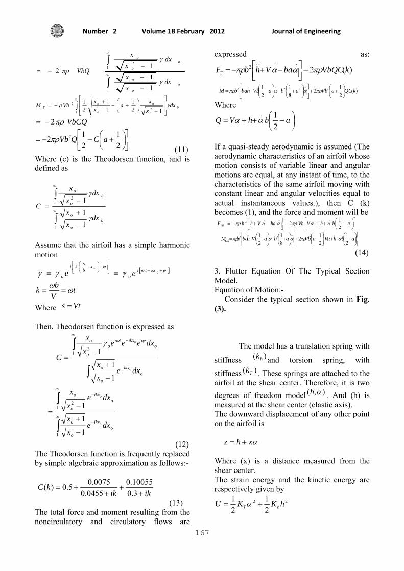
(11) Where (c) is the Theodorsen function, and is defined as
∫
∫∞
∞
−
+
−=
1
12
111
oo
o
o
o
o
dxxx
dxx
x
Cγ
γ
Assume that the airfoil has a simple harmonic motion
[ ]ϕω
ϕγγγ +−⎥
⎦
⎤⎢⎣
⎡+⎟
⎠⎞
⎜⎝⎛ −
== oo kxti
o
xbski
o ee t
Vbk ωω==
Where Vts = Then, Theodorsen function is expressed as
∫
∫
−
∞−
−
+
−=
oikx
o
o
oiikxti
o
o
o
dxexx
dxeeex
x
Co
o
11
112
ϕωγ
∫
∫∞
−
∞−
−
+
−=
1
12
111
oikx
o
o
oikx
o
o
dxexx
dxex
x
o
o
(12) The Theodorsen function is frequently replaced by simple algebraic approximation as follows:-
ikikkC
++
++=
3.010055.0
0455.00075.05.0)(
(13) The total force and moment resulting from the noncirculatory and circulatory flows are
expressed as:
)(2.....
2 kVbQCbaVhbF πρααπρ −⎥⎦⎤
⎢⎣⎡ −+−=Γ
)(
212
81
21 2
..22
...2 kQCaVbabaVbhbabM ⎟
⎠⎞
⎜⎝⎛ ++⎥
⎦
⎤⎢⎣
⎡⎟⎠⎞
⎜⎝⎛ +−⎟
⎠⎞
⎜⎝⎛ −−= πρααπρ
Where
⎟⎠⎞
⎜⎝⎛ −++= abhVQ
21..
αα
If a quasi-steady aerodynamic is assumed (The aerodynamic characteristics of an airfoil whose motion consists of variable linear and angular motions are equal, at any instant of time, to the characteristics of the same airfoil moving with constant linear and angular velocities equal to actual instantaneous values.), then C (k) becomes (1), and the force and moment will be
⎥⎦
⎤⎢⎣
⎡⎟⎠⎞
⎜⎝⎛ −++−⎥⎦
⎤⎢⎣⎡ −+−= abhVVbbaVhbFQS 2
12.......
2 ααπρααπρ
⎥⎦
⎤⎢⎣
⎡⎟⎠⎞
⎜⎝⎛ −++⎟
⎠⎞
⎜⎝⎛ ++⎥
⎦
⎤⎢⎣
⎡⎟⎠⎞
⎜⎝⎛ +−⎟
⎠⎞
⎜⎝⎛ −−= abhVaVbabaVbhbabMQS 2
1212
81
21 ..
2..
2...
2 ααπρααπρ
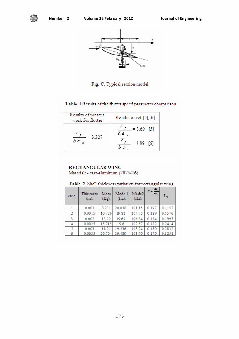
(14) 3. Flutter Equation Of The Typical Section Model. Equation of Motion:- Consider the typical section shown in Fig. (3).
The model has a translation spring with
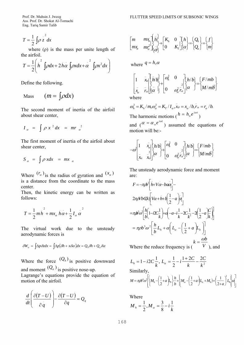
stiffness )( hk and torsion spring, with stiffness )( Tk . These springs are attached to the airfoil at the shear center. Therefore, it is two degrees of freedom model ),( αh . And (h) is measured at the shear center (elastic axis). The downward displacement of any other point on the airfoil is αxhz += Where (x) is a distance measured from the shear center. The strain energy and the kinetic energy are respectively given by
22
21
21 hKKU hT += α
FLUTTER SPEED LIMITS OF SUBSONIC WINGS Prof. Dr. Muhsin J. Jweeg Ass. Prof. Dr. Shokat Al-Tornachi Eng. Tariq Samir Talib
168
dxzT
2.
21∫= ρ
where (ρ) is the mass per unite length of the airfoil.
⎟⎟⎠
⎞⎜⎜⎝
⎛++= ∫ ∫ ∫ dxxxdxhdxhT 2
2...2.2
21 ραραρ
Define the following. Mass )( ∫= dxm ρ The second moment of inertia of the airfoil about shear center,
∫ == 22αα ρ mrdxxI
The first moment of inertia of the airfoil about shear center,
∫ == αα ρ mxxdxS
Where )( αr is the radius of gyration and )( αx is a distance from the coordinate to the mass center. Then, the kinetic energy can be written as follows:
2...2.
21
21 αα αα IhmxhmT ++=
The virtual work due to the unsteady aerodynamic forces is
∫ ∫ +=+∆=∆= δαδδαδδδ αα QhQdxxhpzdxpW h
Where the force )( hQ is positive downward
and moment )( αQ is positive nose-up. Lagrange’s equations provide the equation of motion of the airfoil.
qUT
q
UTdtd
=∂−∂
−⎟⎟⎟
⎠
⎞
⎜⎜⎜
⎝
⎛
∂
−∂.
⎭⎬⎫
⎩⎨⎧
=⎭⎬⎫
⎩⎨⎧
=⎭⎬⎫
⎩⎨⎧⎥⎦
⎤⎢⎣
⎡+
⎪⎭
⎪⎬⎫
⎪⎩
⎪⎨⎧⎥⎦
⎤⎢⎣
⎡mf
QQh
KKh
mr
mxmxm h
T
h
αα
α
α αα
00..
..
2
where α,hq =
⎭⎬⎫
⎩⎨⎧
=⎭⎬⎫
⎩⎨⎧⎥⎥
⎦
⎤
⎢⎢
⎣
⎡+⎪⎭
⎪⎬⎫
⎪⎩
⎪⎨⎧
⎥⎥⎥
⎦
⎤
⎢⎢⎢
⎣
⎡
22_2
2
..
..
_
_
_ ///0
0
/1mbMmbFbh
r
bh
r
x
x
h
αω
ω
α ααα
α
α where
./,/,/,/__
22 brrbxxIKmK Thh αααθααωω ==== The harmonic motions (
tio ehh ω= )
and (ti
o e ωαα = ) assumed the equations of motion will be:-
⎭⎬⎫
⎩⎨⎧
=⎭⎬⎫
⎩⎨⎧⎥⎥
⎦
⎤
⎢⎢
⎣
⎡+⎭⎬⎫
⎩⎨⎧
⎥⎥⎥
⎦
⎤
⎢⎢⎢
⎣
⎡−
22_2
2
2_
_
_
2
///0
0
/1
mbMmbFbh
r
bh
x
x
x
h
αω
ω
αω
ααα
α
α The unsteady aerodynamic force and moment are:
⎥⎦
⎤⎢⎣
⎡⎟⎠⎞
⎜⎝⎛ −++
−⎥⎦⎤
⎢⎣⎡ −+−=
..
.....2
21)(2 ααπρ
ααπρ
abhVkVbC
baVhbF
⎥⎦
⎤⎢⎣
⎡⎟⎟⎠
⎞⎜⎜⎝
⎛⎟⎠⎞
⎜⎝⎛ −−−−−+⎟
⎠⎞
⎜⎝⎛ −=
kCai
kC
kia
kCi
bhb
212121121 2
23 αωπρ
⎥⎦
⎤⎢⎣
⎡⎟⎟⎠
⎞⎜⎜⎝
⎛⎟⎠⎞
⎜⎝⎛ +−+= hh LaLL
bhb
2123
ααωπρ
Where the reduce frequency is ( Vbk ω
=), and
,121k
CiLh −= 2
22121
kC
kCiL −
+−=α
Similarly,
( )⎥⎥⎦
⎤
⎢⎢⎣
⎡
⎪⎭
⎪⎬⎫
⎪⎩
⎪⎨⎧
⎟⎠⎞
⎜⎝⎛+
++⎟⎠⎞
⎜⎝⎛ +−+
⎭⎬⎫
⎩⎨⎧
⎟⎠⎞
⎜⎝⎛ +−= αωπρ αα hhhh L
aMLaM
bh
LaMbM2
24
21
21
21
Where
kiMM h
183,
21
−== α
Journal of Engineering Volume 18 February 2012 Number 2
169
Then, the equation of motion can be rewritten as:
⎭⎬⎫
⎩⎨⎧⎥⎥
⎦
⎤
⎢⎢
⎣
⎡+
⎭⎬⎫
⎩⎨⎧
⎥⎥⎥
⎦
⎤
⎢⎢⎢
⎣
⎡−
αω
ω
αω
ααα
α
α
bh
r
bh
r
x
x
h /0
0
/12_
2
2
2_
_
_
2
⎭⎬⎫
⎩⎨⎧
⎥⎥⎥⎥
⎦
⎤
⎟⎠⎞
⎜⎝⎛ +++⎟
⎠⎞
⎜⎝⎛ +−
⎟⎠⎞
⎜⎝⎛ +−
⎢⎢⎢⎢
⎣
⎡
⎟⎠⎞
⎜⎝⎛ +−
=αµ
ω
αα
α bh
LaMLaM
LaL
LaM
L
hh
h
hh
h /
21)(
21
21
21 2
2
(15) where the mass ratio is defined as:
(2b
mπρ
µ =), (m) is the airfoil mass per unit
length.
Define (2
22
αωω
=Ω) and (
2
22
αωωhR =
), then
⎭⎬⎫
⎩⎨⎧⎥⎥
⎦
⎤
⎢⎢
⎣
⎡+
⎭⎬⎫
⎩⎨⎧
⎥⎥⎥
⎦
⎤
⎢⎢⎢
⎣
⎡Ω−
αααα
α
α
bh
r
Rbh
r
x
x
/0
0
/12_
2
2_
_
_
2
⎭⎬⎫
⎩⎨⎧
⎥⎥⎥⎥
⎦
⎤
⎟⎠⎞
⎜⎝⎛ +++⎟
⎠⎞
⎜⎝⎛ +−
⎟⎠⎞
⎜⎝⎛ +−
⎢⎢⎢⎢
⎣
⎡
⎟⎠⎞
⎜⎝⎛ +−
Ω=
αµαα
α bh
LaMLaM
LaL
LaM
L
hh
h
hh
h/
21)(
21
21
21 2
2
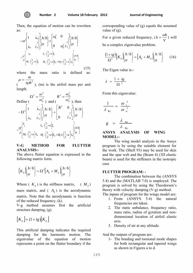
V-G METHOD FOR FLUTTER ANALYSIS:- The above flutter equation is expressed in the following matrix form.
[ ] [ ]⎭⎬⎫
⎩⎨⎧
+Ω=⎭⎬⎫
⎩⎨⎧
ααbh
MAbh
K ijijij
// 2
Where ( ijK ) is the stiffness matrix, ( ijM ) mass matrix, and ( ijA ) is the aerodynamic matrix. Note that the aerodynamic is function of the reduced frequency, (k). V-g method assumes first the artificial structure damping, (g). [ ] [ ]ijij KigK )1( += This artificial damping indicates the required damping for the harmonic motion. The eigenvalue of the equation of motion represents a point on the flutter boundary if the
corresponding value of (g) equals the assumed value of (g).
For a given reduced frequency, (Vbk ω
= ) will
be a complex eigenvalue problem.
( ) [ ] [ ]⎭⎬⎫
⎩⎨⎧
+=⎭⎬⎫
⎩⎨⎧
Ω+
ααbh
MAbh
Kigijijij
//12 (16)
The Eigen value is:-
2
1Ω+
=igλ
From this eigenvalue:
2
2
Re
1
αωω
λi=
Re
Im
λλ
=g
ANSYS ANALYSIS OF WING MODEL:- The wing model analysis in the Ansys program is by using the suitable element for the work. The (Shell 93) may be used for skin and the spar web and the (Beam 4) (3D elastic beam) is used for the stiffeners in the isotropic case FLUTTER PROGRAM: -
The combination between the (ANSYS 5.4) and the (MATLAB 7.0) is employed. The program is solved by using the Theodorsen’s theory with velocity damping (V-g) method. The inputs of program for the wings model are:
1. From (ANSYS 5.4) the natural frequencies are taken.
2. The static unbalance, frequency ratio, mass ratio, radius of gyration and non-dimensional location of airfoil elastic axis.
3. Density of air at any altitude.
And the outputs of program are: 1- The bending and torsional mode shapes
for both rectangular and tapered wings as shown in Figures a to d.
FLUTTER SPEED LIMITS OF SUBSONIC WINGS Prof. Dr. Muhsin J. Jweeg Ass. Prof. Dr. Shokat Al-Tornachi Eng. Tariq Samir Talib
170
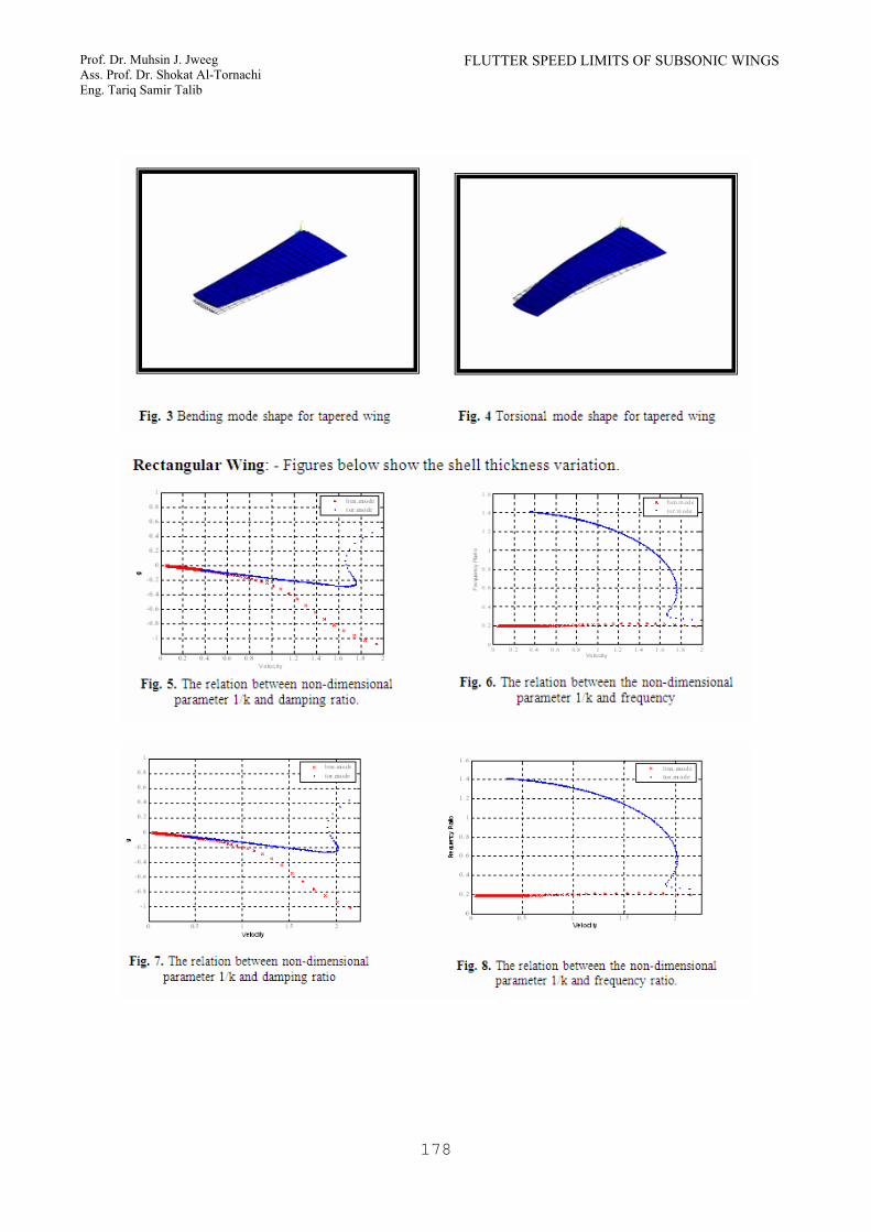
2- The relation between the non- dimensional parameter (1/k) with structural damping.
3- Calculation of the flutter speed. RESULTS AND DISCUSSIONS:-
RESULTS OF COMPARISON: - By using analytical and numerical
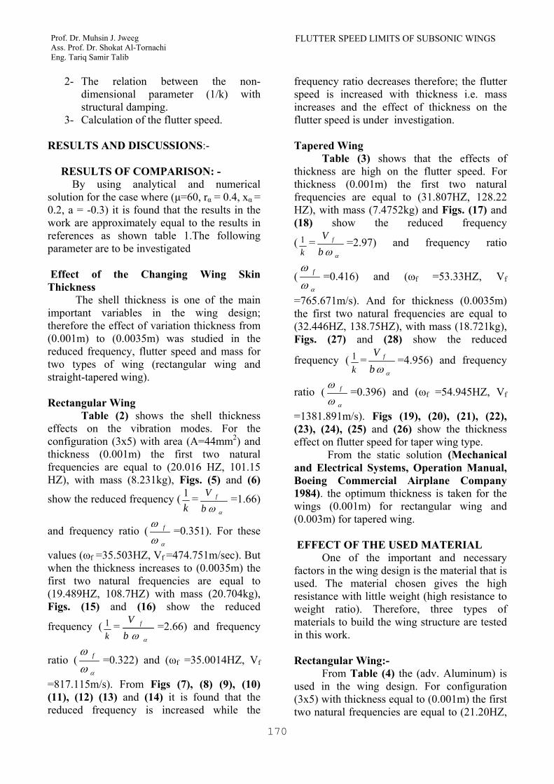
solution for the case where (µ=60, rα = 0.4, xα = 0.2, a = -0.3) it is found that the results in the work are approximately equal to the results in references as shown table 1.The following parameter are to be investigated Effect of the Changing Wing Skin Thickness The shell thickness is one of the main important variables in the wing design; therefore the effect of variation thickness from (0.001m) to (0.0035m) was studied in the reduced frequency, flutter speed and mass for two types of wing (rectangular wing and straight-tapered wing). Rectangular Wing
Table (2) shows the shell thickness effects on the vibration modes. For the configuration (3x5) with area (A=44mm2) and thickness (0.001m) the first two natural frequencies are equal to (20.016 HZ, 101.15 HZ), with mass (8.231kg), Figs. (5) and (6)
show the reduced frequency (k1 =
αωbV f =1.66)
and frequency ratio (αω
ω f =0.351). For these
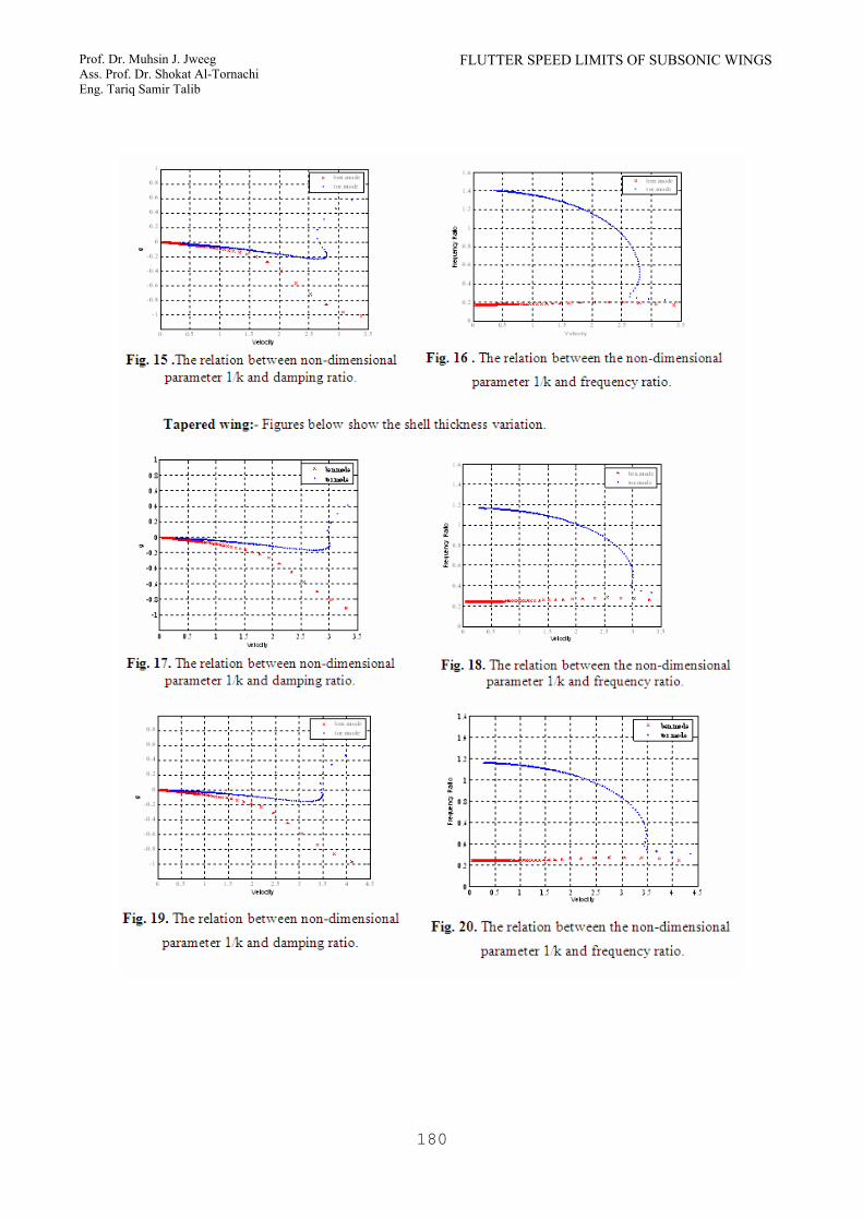
values (ωf =35.503HZ, Vf =474.751m/sec). But when the thickness increases to (0.0035m) the first two natural frequencies are equal to (19.489HZ, 108.7HZ) with mass (20.704kg), Figs. (15) and (16) show the reduced
frequency (k1 =
αωbV f =2.66) and frequency
ratio (αω
ω f =0.322) and (ωf =35.0014HZ, Vf
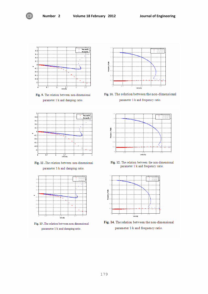
=817.115m/s). From Figs (7), (8) (9), (10) (11), (12) (13) and (14) it is found that the reduced frequency is increased while the
frequency ratio decreases therefore; the flutter speed is increased with thickness i.e. mass increases and the effect of thickness on the flutter speed is under investigation.
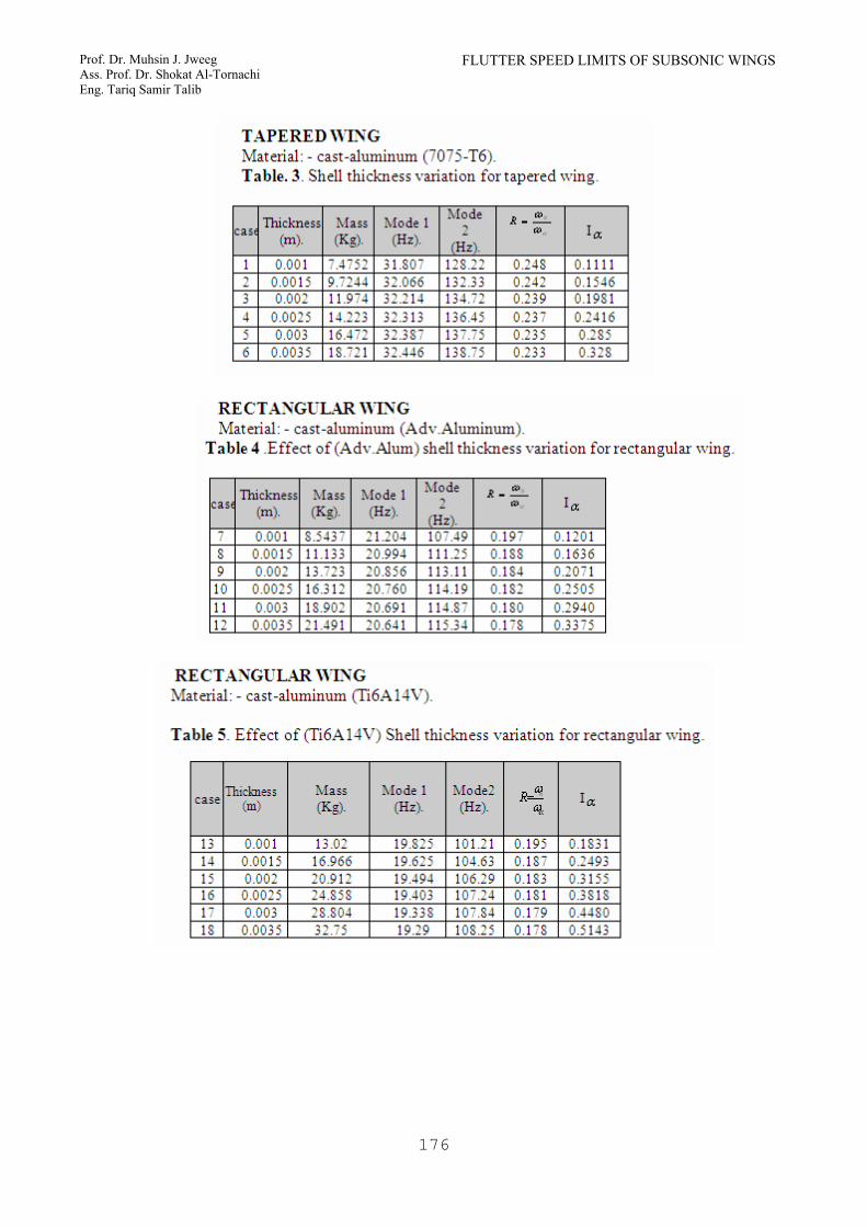
Tapered Wing Table (3) shows that the effects of thickness are high on the flutter speed. For thickness (0.001m) the first two natural frequencies are equal to (31.807HZ, 128.22 HZ), with mass (7.4752kg) and Figs. (17) and (18) show the reduced frequency
(k1 =
αωbV f =2.97) and frequency ratio
(αω
ω f =0.416) and (ωf =53.33HZ, Vf
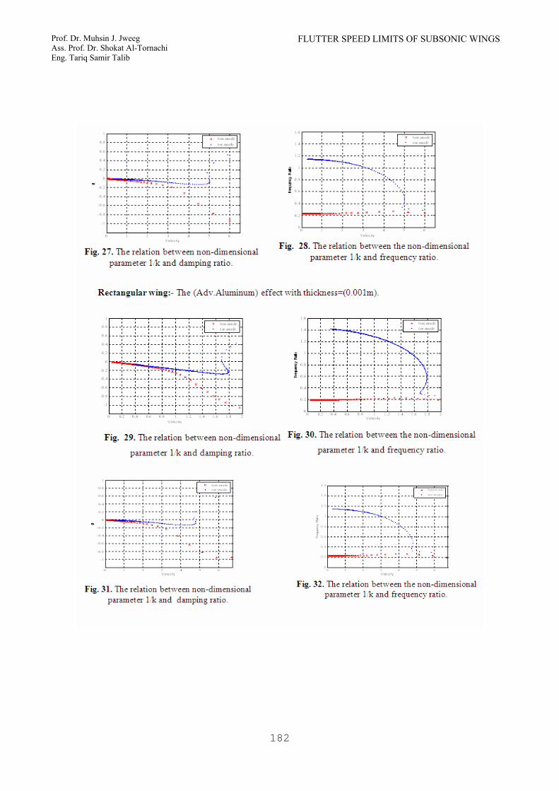
=765.671m/s). And for thickness (0.0035m) the first two natural frequencies are equal to (32.446HZ, 138.75HZ), with mass (18.721kg), Figs. (27) and (28) show the reduced
frequency (k1 =
αωbV f =4.956) and frequency
ratio (αω
ω f =0.396) and (ωf =54.945HZ, Vf
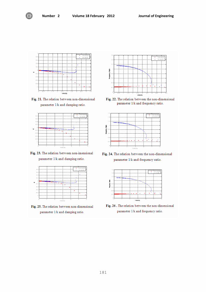
=1381.891m/s). Figs (19), (20), (21), (22), (23), (24), (25) and (26) show the thickness effect on flutter speed for taper wing type.
From the static solution (Mechanical and Electrical Systems, Operation Manual, Boeing Commercial Airplane Company 1984). the optimum thickness is taken for the wings (0.001m) for rectangular wing and (0.003m) for tapered wing. EFFECT OF THE USED MATERIAL One of the important and necessary factors in the wing design is the material that is used. The material chosen gives the high resistance with little weight (high resistance to weight ratio). Therefore, three types of materials to build the wing structure are tested in this work. Rectangular Wing:- From Table (4) the (adv. Aluminum) is used in the wing design. For configuration (3x5) with thickness equal to (0.001m) the first two natural frequencies are equal to (21.20HZ,
Journal of Engineering Volume 18 February 2012 Number 2
171
107.49HZ) with mass (8.5437kg) and Figs. (29) and (30) show the reduced frequency
(k1 =
αωbV f =1.688) and frequency ratio
(αω
ω f =0.337) and (ωf =36.22HZ, Vf
=513.018m/s). And for the same thickness for (7075-T6) the first two natural frequencies are equal to (20.016 HZ, 101.15 HZ), with mass (8.231kg) and Figs. (5) and (6) show the
reduced frequency (k1 =
αωbV f =1.66) and
frequency ratio (αω
ω f =0.351). For these
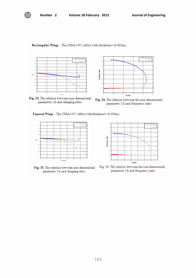
values (ωf =35.503HZ, Vf =474.751m/sec). From Table (5) and for the same thickness when using the (Ti6A14V) the first two natural frequencies are equal to (19.825HZ, 101.21HZ) with mass (13.02 kg). Figs. (33) and (34) show the reduced frequency
(k1
=αωb
V f =2.044) and frequency ratio
(αω
ω f =0.327) and (ωf =33.095HZ, Vf
=584.624m/s). From above it is clear that the effects of the materials (7075-T6) and (Adv.Aluminum) are approximately equal in angular flutter frequency but the difference in the flutter speed is equal to (7.45%) using the same mass. But when using (Ti6A14V) the angular flutter frequency is less than the (7075-T6) and (Adv.Aluminum) while the flutter speed is greater with high value of mass. The percentage between (Ti6A14V) and (7075-T6) is equal to (18.7%), and (Ti6A14V), (Adv.Aluminum) is equal to (12.2%). The percentages differ because of the wing mass difference. TAPERED WING
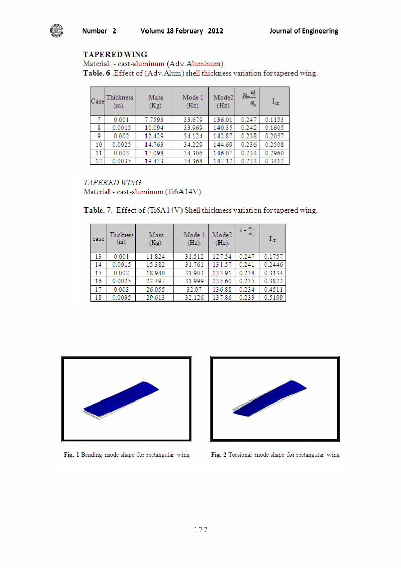
From Table (6),and when using the (adv. Aluminum) in the wing design with changing thickness, it is seen that for configuration (3x5) with thickness equal to (0.003m) the first two natural frequencies are equal to (34.306HZ, 146.07HZ) with mass (17.098kg), Figs. (31) and (32) show the
reduced frequency (k1 =
αωbV f =4.769) and
frequency ratio (αω
ω f =0.429) and (ωf
=62.66HZ, Vf =1399.903m/s). And for the same thickness for (7075-T6) the first two natural frequencies are equal to (32.387HZ, 137.75HZ), with mass (16.472kg), Figs. (13) and (14) show the reduced frequency
(k1
=αωb
Vf =4.675) and frequency ratio
(αω
ω f=0.421) and (ωf =57.992HZ, Vf
=1294.144m/sec). From Table (7) and for the same thickness when using the (Ti6A14V) the first two natural frequencies are equal to (32.07HZ, 136.88HZ) with mass (26.055kg), Figs. (35) and (36) show the reduced
frequency (k1
=αωb
Vf =5.79) and frequency ratio
(αω
ω f =0.405) and (ωf =55.436HZ, Vf
=1592.679m/s). From above, it is found that the effects of the materials (7075-T6) and (Adv.Aluminum) are different in angular flutter frequency but the flutter speed difference percentage is equal to (7.5%) with the same mass approximately. But when using (Ti6A14V) it is found that the angular flutter frequency is less than the (7075-T6) and (Adv.Aluminum) while the flutter speed is greater with high value for mass. The percentage difference between (Ti6A14V) and (7075-T6) is equal to (18.7%) and (Ti6A14V) (Adv.Aluminum) is equal to (12.2%). These differences are because of the wing mass difference.
From above, the material (7075-T6) is recommended for both wings rectangular and taper because it gives good results for flutter speed and angular flutter frequency with little mass. Figs. (1) and (2) show the bending and torsion mode shapes and the corresponding deformations of the material, type (7075-T6) in configuration (3x5) and shell thickness (0.001m) with beam cross section area of
FLUTTER SPEED LIMITS OF SUBSONIC WINGS Prof. Dr. Muhsin J. Jweeg Ass. Prof. Dr. Shokat Al-Tornachi Eng. Tariq Samir Talib
172
(44x10-6m2). These deformations are due to free vibration in the rectangular wing. Figs. (3) and (4) show the bending and torsion mode shapes and the corresponding deformations of the material, type (7075-T6) in configuration (3x5) and shell thickness (0.003m) with beam cross section area of (44x10-6m2). These deformations are due to free vibration of the tapered wing.
CONCLUSIONS From the results achieved in this work the following points may be concluded. Increase of radius of gyration (rα) tends to increase the flutter speed especially for higher mass ratio. The static unbalance (xα) increases (the distance between the rotation center and center of gravity) the flutter speed decreases because of the strong coupling between heaving and pitching motion.
• The flutter speed is sensitive to the ratio of uncoupling natural frequencies, where the increasing of the frequency ratio increases the flutter speed and the flutter speed has a minimum near
( 1=αω
ωh ).With structure damping
omitted the typical section model is neutrally stable until (V = Vf) for (V = Vf) the bending and torsion frequencies merge and for (V > Vf) the system is unstable.
• With including structure damping (g) for small (V) all values of structure damping (g) are stable and flutter speed is sufficiently large (V) where structure damping (g) changes its sign from negative to positive.
• The higher wing aspect ratio decreases the flutter speed, while the increasing of the taper ratio increases the flutter speed. The flutter speed changes linearly with the altitude and it is increased with increasing the altitude. Flutter prevention can be summarized by adding mass or redistribute mass so that (xα < 0) mass balance, increases torsional stiffness i.e. increase (ωα),
Increasing or decreasing (αω
ωh ) if it is
near one (for fixed ωα), adding damping to the structure and require the aircraft to be flown below its critical mach number.
REFERENCES:-
• Bala Krishnan A.V. (2003), Toward a Mathematical Theory of Aero elasticity Flight Systems Research Center. UCLA.
• Darrol Stinton. (1989), The Design of the Aeroplane. Bsp. Professional Books Oxford, England.
• Massimo Bianchin, Giuseppe
Quarantay, Paolo Mantegazza. (2003), State Space Reduced Order Models for Static Aeroelasticity and Flight Mechanics of Flexible Aircrafts. Department of Engineering, Milano. Italy.
• Mechanical and Electrical Systems
(1984). Operation Manual, Boeing Commercial Airplane Company.
• Sadeghi M., Yangy S., Liuz F., Tsaix
H. M. (2003), Parallel Computation of Wing Flutter with a Coupled Navier-Stokes/CSD Method. AIAA 1347.
• Theodore Theodorsen. (1935), General
Theory of Aerodynamic Instability and the Mechanism of Flutter. NACA Report No.496.
• Ueda T. and Dowell E. H. (1984),
Flutter Analysis Using Nonlinear Aerodynamic Force. J. of Aircraft, Vol.12, No.2.
• Yang T. Y. (1980), Flutter Analysis of
a NACA 64A006 Airfoil in Small Disturbance Transonic Flow. J. of Aircraft, Vol.17.
Journal of Engineering Volume 18 February 2012 Number 2
173
Symbols:-
FLUTTER SPEED LIMITS OF SUBSONIC WINGS Prof. Dr. Muhsin J. Jweeg Ass. Prof. Dr. Shokat Al-Tornachi Eng. Tariq Samir Talib
174
Journal of Engineering Volume 18 February 2012 Number 2
175
FLUTTER SPEED LIMITS OF SUBSONIC WINGS Prof. Dr. Muhsin J. Jweeg Ass. Prof. Dr. Shokat Al-Tornachi Eng. Tariq Samir Talib
176
Journal of Engineering Volume 18 February 2012 Number 2
177
FLUTTER SPEED LIMITS OF SUBSONIC WINGS Prof. Dr. Muhsin J. Jweeg Ass. Prof. Dr. Shokat Al-Tornachi Eng. Tariq Samir Talib
178
Journal of Engineering Volume 18 February 2012 Number 2
179
FLUTTER SPEED LIMITS OF SUBSONIC WINGS Prof. Dr. Muhsin J. Jweeg Ass. Prof. Dr. Shokat Al-Tornachi Eng. Tariq Samir Talib
180
Journal of Engineering Volume 18 February 2012 Number 2
181
FLUTTER SPEED LIMITS OF SUBSONIC WINGS Prof. Dr. Muhsin J. Jweeg Ass. Prof. Dr. Shokat Al-Tornachi Eng. Tariq Samir Talib
182
Journal of Engineering Volume 18 February 2012 Number 2
183