flowcat – a versatile continuous flow reactor system ... article sept...the safety and energy...
TRANSCRIPT
1 FlowCAT - a versatile continuous flow reactor system
September 2011 http://www.helgroup.com
FlowCAT – a versatile continuous flow reactor
system focusing on reactions under elevated pressure
and/or involving heterogeneous catalysis.
By Dr Jasbir Singh
1 Introduction
An upsurge in catalytic activity, primarily in relation to hydrogenation reactions, is widely
recognised in the pharmaceutical and related industries. In the last couple of years, there has
also be an increasing interest in flow chemistry, quite new to the pharmaceutical and fine
chemicals industry though well established in other sectors, especially petrochemical and
refining. This has highlighted the need for a research scale apparatus which enables high
pressure flow chemistry to be conducted safely by chemists who are neither specialists in
pressure equipment nor flow processes.
The FlowCAT is introduced as such a device, small scale high pressure flow reactor unit
ideally suited to heterogeneous catalysis under pressure but able to handle all-liquid
chemistries even down to atmospheric pressure. In pharmaceutical context, the system is
targeted at post med-chem and discovery stages though the ability to produce fairly large
amounts of sample lends itself to these early stages too. In the chemical industry generally, it
is a research scale unit that allows easy and successful scale-up.
2 FlowCAT Reactor system
2.1 Flow chemistry – general features and benefits
Flow reactors have the advantage over stirred vessels that fluids can be pumped through the
reactor and hence even for relatively large production rates the reactor is often just a pipe
rather than a big cylindrical vessel with a voluminous inventory. This is especially true if the
reaction rate is fast and hence the reactants can be passed through the “pipe” at a high flow
rate enabling the reactor to be even smaller.
The safety and energy advantages of flow reactors follow from the reduced inventory and
much simpler hardware. From a process viewpoint too there are advantages as the simple
pipe can be used at higher pressure and temperature if necessary, allowing more extreme
conditions to be realised without excessive cost.
Flow reactors can be used in all sorts of configurations the simplest being to take a coiled
length of metal or plastic tube which is held at a controlled temperature. This is ideal for
2 FlowCAT - a versatile continuous flow reactor system
September 2011 http://www.helgroup.com
some situations especially in the laboratory but the but the one most commonly found is
tubular design which maybe only 5-20cm long with machined ends and diameter large
enough to take powder catalyst if necessary. This is often but is relatively short held
vertically within a heated zone and feeds introduced from the top and product withdrawn
from the bottom. Where the catalyst is a powder, this is normally held in position to form a
solid pack, “packed bed”, through which the reactants flow.
2.2 Design Features of FlowCAT
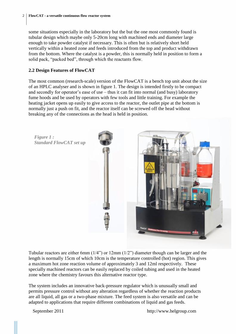
The most common (research-scale) version of the FlowCAT is a bench top unit about the size
of an HPLC analyser and is shown in figure 1. The design is intended firstly to be compact
and secondly for operator’s ease of use – thus it can fit into normal (and busy) laboratory
fume hoods and be used by operators with few tools and little training. For example the
heating jacket opens up easily to give access to the reactor, the outlet pipe at the bottom is
normally just a push on fit, and the reactor itself can be screwed off the head without
breaking any of the connections as the head is held in position.
Tubular reactors are either 6mm (1/4”) or 12mm (1/2”) diameter though can be larger and the
length is normally 15cm of which 10cm is the temperature controlled (hot) region. This gives
a maximum hot zone reaction volume of approximately 3 and 12ml respectively. These
specially machined reactors can be easily replaced by coiled tubing and used in the heated
zone where the chemistry favours this alternative reactor type.
The system includes an innovative back-pressure regulator which is unusually small and
permits pressure control without any alteration regardless of whether the reaction products
are all liquid, all gas or a two-phase mixture. The feed system is also versatile and can be
adapted to applications that require different combinations of liquid and gas feeds.
Figure 1 :
Standard FlowCAT set up

3 FlowCAT - a versatile continuous flow reactor system
September 2011 http://www.helgroup.com
2.3 FlowCAT Controls
The FlowCAT unit is software controlled with independent control of feed rates, working
pressure and temperature and the mimic diagram of the set up for the standard configuration
used for example for hydrogenations, is shown in figure 2. This shows one controlled gas and
one liquid feed plus a manual nitrogen purge. The feeds are preheated and then pass through
the main body of the reactor and the product then leaves the high pressure section after
passing through the back pressure control valve.
Figure 2: Mimic of standard FlowCAT set up for hydrogenation
A totally different set up is shown in figure 3 where there are three separate gas feeds and one
liquid, and these involve some pre-treatment before entering the reactor. The reactor itself
actually has no catalyst packing and the product is analysed in real-time by means of an
analyser piped upstream of the pressure control valve. The analyser readings are accessed and
displayed in real-time along with process data.

4 FlowCAT - a versatile continuous flow reactor system
September 2011 http://www.helgroup.com
Figure 3: Example of Modified set up with on-line product analyser
2.4 Operating window – trickle flow region
In principle, any flow rate of gases and liquids can be passed through a given reactor
provided the pumps can overcome the pressure drop. In reality, best performance is obtained
if the flow pattern is what is called “trickle-flow” and this also then can be used as the basis
for scale-up. The ranges of gas and liquid flows which will lead to trickle-flow are shown on
figure 4 (which also indicates the flow pattern at rates beyond the trickle-flow band).

5 FlowCAT - a versatile continuous flow reactor system
September 2011 http://www.helgroup.com
Figure 5 shows the trickle-flow region in more detail but also plotted is the region occupied
by the standard FlowCAT (and as an illustration, the data points for the carbonylation
reaction studies reported in section 5 of this article are also marked).
Loading of solid catalyst to the reactor is also an important part of operation and
reproducibility of results. It is common practice to have a top section packed with inert
particles (such as glass beads) which helps to preheat and mix the feeds. The reaction section
itself also can contain inerts mixed with catalyst particles, thus helping to spread a given
amount of catalyst over a bigger volume which assists with temperature control and gives
more reproducible results.
Figure 4 : Flow pattern in packed tubular reactors at different flow rates

6 FlowCAT - a versatile continuous flow reactor system
September 2011 http://www.helgroup.com
Figure 5: Working range of standard FlowCAT to give trickle flow
3 Hydrogenation of nitrobenzene
The first reaction presented is the hydrogenation of nitrobenzene to aniline using 1% Pd on
carbon catalyst (around 0.1g) mixed with glass beads (around 400 micron diameter). Most of
the experiments were done at 30C, using substrate/solvent flow rate of 0.5ml/minute and 20
litre/minute of hydrogen, corresponding approximately to 1.83 times stoichiometric of the
gas. Taking into account the volume occupied by the inert beads, the void space available for
reactant flow was around 1.2ml and therefore, the residence time is around 2.4 minutes.
The results are plotted in figure 6, where the amount of hydrogen consumed is plotted at
different working pressures. Also shown is the solubility of hydrogen in the solvent at
different pressures; clearly, the consumption is not limited by solubility. The gas
consumption values in fact correspond to substrate conversion of around 20% at the lowest
pressure rising to around 60% at 90bar.
To increase conversion, temperature could be increased and residence time could be
increased (for example by reducing the liquid flow rate). These changes could be made while
the reactor is still working, without any need to stop the experiment and change the
equipment. This is one great advantage compared with batch reactors where the system
would need to be dismantled, reactors washed, cleaned and reloaded with freshly weighed
catalyst before different conditions could be attempted.
Operating range of FlowCAT used for carbonylation study
0.001
0.01
0.1
1
10
0.001 0.01 0.1 1 10 100
Liquid flow rate (kgm-2
s-1
)
Gas f
low
rate
(kg
m-2
s-1
)
Carbonylation data
FLOWCAT
Bench scale
Pilot plant
Industrial unit

7 FlowCAT - a versatile continuous flow reactor system
September 2011 http://www.helgroup.com
Figure6: Hydrogenation of nitrobenzene to aniline at different pressures
If flow rate is reduced to increase conversion, then of course throughput is compromised. In
order to avoid this, it would be possible to reduce the amount of inert packing to free up more
space or alternately switch to a larger diameter reactor.
4 Sterioselective hydrogenation
Pfizer pharmaceutical company reported the benefits of using the FlowCAT to perform a
hydrogenation where sterioselectivity control was important and they showed that control of
the cis to trans ratio in the product could be tuned by adjusting the pressure. The chemistry in
question is summarised in below and the results they achieved which show the “tuning”
capability with a flow reactor is plotted in figure 7.
0
0.05
0.1
0.15
0.2
0.25
0.3
0.35
0 20 40 60 80 100
Gas c
on
su
mp
tio
n (
mm
ol/m
in)
Pressure (bar)
H2 Saturation
0.5 ml/minLiquid flow
8 FlowCAT - a versatile continuous flow reactor system
September 2011 http://www.helgroup.com
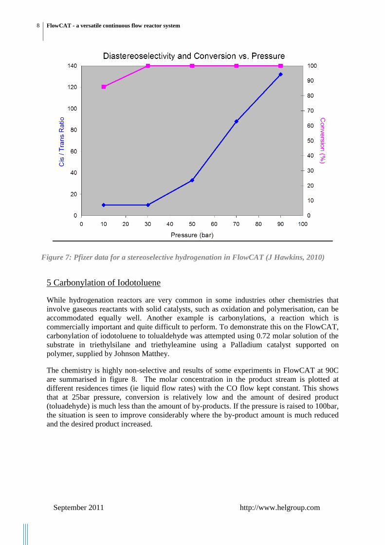
5 Carbonylation of Iodotoluene
While hydrogenation reactors are very common in some industries other chemistries that
involve gaseous reactants with solid catalysts, such as oxidation and polymerisation, can be
accommodated equally well. Another example is carbonylations, a reaction which is
commercially important and quite difficult to perform. To demonstrate this on the FlowCAT,
carbonylation of iodotoluene to tolualdehyde was attempted using 0.72 molar solution of the
substrate in triethylsilane and triethyleamine using a Palladium catalyst supported on
polymer, supplied by Johnson Matthey.
The chemistry is highly non-selective and results of some experiments in FlowCAT at 90C
are summarised in figure 8. The molar concentration in the product stream is plotted at
different residences times (ie liquid flow rates) with the CO flow kept constant. This shows
that at 25bar pressure, conversion is relatively low and the amount of desired product
(toluadehyde) is much less than the amount of by-products. If the pressure is raised to 100bar,
the situation is seen to improve considerably where the by-product amount is much reduced
and the desired product increased.
Figure 7: Pfizer data for a stereoselective hydrogenation in FlowCAT (J Hawkins, 2010)

9 FlowCAT - a versatile continuous flow reactor system
September 2011 http://www.helgroup.com
The same reaction was also performed in a small batch reactor at the same conditions and the
results of the two systems are compared in figure 9. This shows that in fact the product slate
under batch and flow conditions is quite similar. Additional batch experiments were
performed at higher reaction times than on the FlowCAT and it seems that this does not
favour the chemistry, certainly after around 150 minutes increasing amount of by-product is
formed at the expense of the desired product.
Products produced during carbonylation of iodotoluene in the FlowCAT
(mantle at 90oC)
0
0.1
0.2
0.3
0 30 60 90 120
Residence time (mins)
Co
ncen
trati
on
(M
)
25bar - other products
100bar - tolualdehyde
25bar - tolualdehyde
100bar - other products
Concentrations of products during carbonylation of Iodotoluene in the
FlowCAT and a batch reactor with similar catalyst mass (at 90oC, 100bar)
0
0.2
0.4
0.6
0 50 100 150 200 250 300
Residence time (mins)
Co
ncen
trati
on
(M
/l)
Tolualdehyde
Other products
●● FlowCAT
■■ Batch
Figure8: Carbonylation reaction in FlowCAT at two different pressures
Figure 9: Comparison of batch and continuous flow carbonylations

10 FlowCAT - a versatile continuous flow reactor system
September 2011 http://www.helgroup.com
6 Liquid-liquid reaction in Tubular reactor
It is also quite simple to perform reactions on the FlowCAT that do not involve a gaseous
reactant and this was illustrated by studying the transfer hydrogenation of nitrobenzene to
aniline using cyclohexene as a transfer molecule.
This is a much easier reaction than the carbonylation and selectivity is nearly 100%. With a
back pressure of 2bar, temperatures of between 80 and 110C were studied at different
residence times up to 10 minutes. The results (figure 10) show that in fact 100% conversion
is achieved at these conditions.
7 Liquid-liquid reaction in coiled tube reactor
The standard tubular reactors used in the previous examples are limited when very fast
reactions are performed as the only way to achieve a long residence time is slow down the
feed rate and this is limited both by the pump and eventually poor mixing and heat transfer.
The alternative is to use 1/16” or 1/8” diameter piping which can be coiled to fit the heating
zone. These can be easily fitted to replace the tubular reactors and hence common synthesis
reactions at atmospheric or elevated pressure can be performed easily. Photographs of such a
set up with 1/8” stainless steel tubing is shown below. This is held inside the same heating
jacket as the tubular reactors previously and product leaving the pipe can be under pressure or
simply by gravity.
Transfer hydrogenation of Nitrobenzene by cyclohexene: concentration of aniline as
function of residence time at different temperatures
0
0.05
0.1
0.15
0.2
0.25
0.3
0.35
0 2 4 6 8 10 12
Residence time (mins)
Co
nc
en
tra
tio
n (
M/l
)
T=110oC
T=100oC
T=90oC
T=80oC
100% conversion
Figure 10: Liquid-liquid reaction involving transfer hydrogenation

11 FlowCAT - a versatile continuous flow reactor system
September 2011 http://www.helgroup.com
Figure 11 Coiled Stainless Steel Tube Reactor inside heated jacket
The utility of this arrangement is illustrated by an interesting condensation reaction between
diphenylacetone and benzyl in the a basic environment (typically NaOH):
The feed mixture is a very pale green and product becomes progressively darker with
conversion, eventually becoming an intense purple. Several runs were performed at different
flow rates with the temperature held at 90C and the amount of caustic fixed and the product
collected. The results are shown below with the fresh feed being on the right and then moving
left the residence times are 2,4,6 and 12 minutes.
The same reaction was also performed in a PTFE coiled reactor and the change in colour is
shown in the right hand photograph.

12 FlowCAT - a versatile continuous flow reactor system
September 2011 http://www.helgroup.com
Figure 12 Products at due to different reaction times and PTFE coiled reactor showing
colour change with conversion
8 Chemistry under super-critical conditions
One of the advantages of flow reactors is that very high pressures can be achieved at
relatively low cost and much more safely than in stirred vessels. This opens up the possibility
of using novel solvents that can have exceptional properties at conditions where the solvent is
supercritical. An important example is CO2 which at modest conditions of pressure and
temperature starts to behave most unusually. For example hydrogen becomes totally miscible
with supercritical CO2 and reactions then become much faster as the normal solubility
barriers associated with common liquid solvents, which slow down the chemistry, suddenly
disappear.
Even in its standard form FlowCAT can handle this type of chemistry, the only additional
hardware needed is a booster compressor for CO2 as this gas is normally available at
relatively low pressure.
9 Conclusions
The utility of a versatile, research scale flow reactor has been demonstrated with numerous
reactions. In addition, the FlowCAT is extremely simple to and opens up the possibility of
doing pressure reactions, including hydrogenations, in normal laboratories by chemists who
are not specialists in pressure equipment.
The flowCAT allows all manner of chemistries to be studied interchangeably with virtually
no change in set up being necessary. Feeds of all liquid, all gas and mixtures of gas and
liquid are possible and the same is true for products.

13 FlowCAT - a versatile continuous flow reactor system
September 2011 http://www.helgroup.com
For further details contact:
Marketing, HEL Ltd
9-10 Capital Business Park
Manor Way
Borehamwood WD6 1GW, UK
Tel: +44 (0)20 8736 0640
Email: [email protected]
URL : http://www.helgroup.com