flow measurement devices s
TRANSCRIPT

FFLLOOWW MMEEAASSUURREEMMEENNTT DDEEVVIICCEESS
By
Gertrudys B. Adkins, Ph.D. Division of Water Rights
2006

ii
TABLE OF CONTENT
INTRODUCTION .......................................................................................................................................................1 FLOW MEASUREMENT DEVICES................................................................................................................................1
FLOW MEASUREMENT BASICS...........................................................................................................................2
OPEN CHANNEL FLOW METHODS.....................................................................................................................3 FLOW MEASUREMENT IN OPEN CHANNELS ..............................................................................................................3
Timed Gravimetric Method ................................................................................................................................3 Dilution Method .................................................................................................................................................3 Velocity-Area Method.........................................................................................................................................3 Hydraulic Structure Method...............................................................................................................................4 Slope-hydraulic Radius-Area Method ................................................................................................................4
SELECTION OF A PRIMARY MEASURING DEVICE: WEIR VS. FLUME ...................................................4
WEIRS..........................................................................................................................................................................6 SHARP-CRESTED WEIR .............................................................................................................................................6 BROAD-CRESTED WEIR ............................................................................................................................................7 MODE OF OPERATION...............................................................................................................................................8
WEIR INSTALLATION REQUIREMENTS...........................................................................................................8 REQUIREMENTS FOR SETTING AND OPERATING WEIRS .........................................................................................10
DISCHARGE COMPUTATION PROCEDURE ...................................................................................................10
WEIR FORMULAS BY WEIR TYPE ....................................................................................................................10
QUICK SELECTION GUIDE FOR WEIRS..........................................................................................................12
FLUMES ....................................................................................................................................................................13 LONG-THROATED FLUMES .....................................................................................................................................13 SHORT-THROATED FLUMES....................................................................................................................................14
PRIMARY CHARACTERISTICS OF FLUMES ..................................................................................................16 Parshall Flumes ...............................................................................................................................................16 Cutthroat Flumes..............................................................................................................................................16 Trapezoidal Flumes ..........................................................................................................................................17
FACTORS CONSIDERED IN FLUME SELECTION ........................................................................................................17 TYPICAL FLUME PRICES..........................................................................................................................................18 AREAS YOU SHOULD BE CONCERNED WITH FOR SUCCESSFUL INSTALLATION OF A PARSHALL FLUME ...............19 HEAD MEASUREMENT ............................................................................................................................................19 DISCHARGE COMPUTATION PROCEDURE ................................................................................................................20 DISCHARGE EQUATIONS FOR PARSHALL FLUMES ...................................................................................................21 SUBMERGED FLOW CONDITIONS ............................................................................................................................21
CRITICAL ASPECTS ON FLUMES INSTALLATION, MAINTENANCE, AND OPERATION ..................24
INSTRUCTION FOR PLACING FLUMES...........................................................................................................27

iii
QUICK SELECTION GUIDE FOR FLUMES ......................................................................................................28
REFERENCES ..........................................................................................................................................................29

iv
LIST OF TABLES
Table 1: Conversion Factors Used in Water Measurement. ...............................2
Table 2: Weir formulas ........................................................................................11
Table 3: Prices for various types of flumes..........................................................18
Table 4: Parshall flume discharge equations adapted from the ISCO Open Channel Flow Measurement Handbook – 5th Edition ................................21

v
LIST OF FIGURES
Figure 1: Weirs Diagrams .......................................................................................7
Figure 2: V-Notch Weir in the Field ......................................................................8
Figure 3: Ramp flume...........................................................................................14
Figure 4: Parshall Flume Configuration Diagrams............................................15
Figure 5: Parshall Flume Installed in a Channel ................................................16
1
INTRODUCTION
Flow Measurement Devices
Increasing utilization and the value of water makes the understanding of water
measuring techniques important and necessary. Accurate flow measurement is
very important for proper and equitable distribution of water among water users.
Information concerning the volume of available water is very helpful in planning
for its future use and distribution.
There are several types of flow measurement devices currently in use across
the United States by private, local, state, and federal agencies. Among the major
types of measurement devices used in surface water (open channels) and/or closed
conduits are: weirs, flumes, current meters, orifices, propeller meters, strain gage,
venturi meters, paddle wheels, electromagnetic, turbine meters, ultrasonic meters,
pitot tubes, elbow tab meters, vortex shedding, mass meters, and orifice plates.
The most common water measurement devices in Utah are sharp crested weirs and
parshall flumes.
2
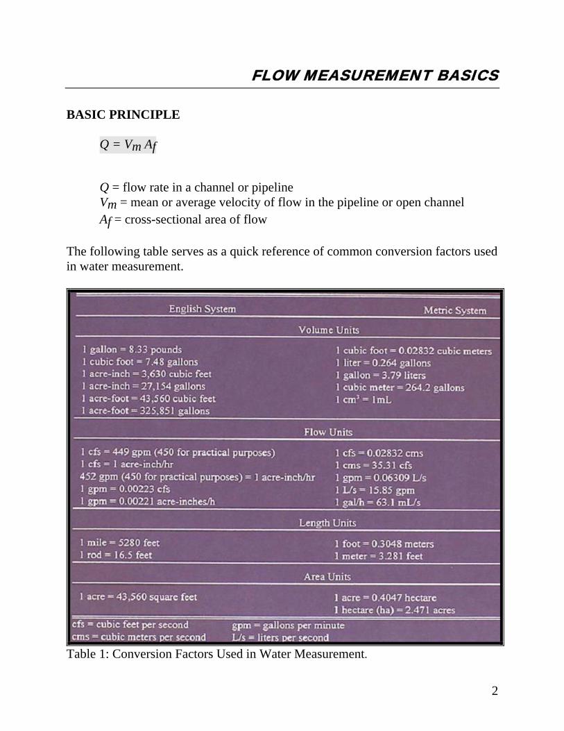
FLOW MEASUREMENT BASICS BASIC PRINCIPLE
Q = Vm Af
Q = flow rate in a channel or pipeline Vm = mean or average velocity of flow in the pipeline or open channel Af = cross-sectional area of flow
The following table serves as a quick reference of common conversion factors used in water measurement.
Table 1: Conversion Factors Used in Water Measurement.

3
OPEN CHANNEL FLOW METHODS Flow Measurement In Open Channels Open channel flow is flow in any channel in which the liquid flows with a free
surface. Included are tunnels, partially filled pipes, canals, streams, and rivers.
There are many methods of determining the rate of flow in open channels. Some
of the more common include the timed gravimetric, dilution, velocity-area,
hydraulic structures, and slope-hydraulic radius-area methods.
Timed Gravimetric Method
The flow rate is calculated by weighing the entire content of the flow stream
that was collected in a container for a fixed length of time. This is practical for
small streams of less than 25 to 30 gallons per minutes (gpm) and is not well suited
for continuous measurement.
Dilution Method
The flow rate is measured by determining how much the flowing water
dilutes an added tracer solution.
Velocity-Area Method
Measuring the mean flow velocity across a cross section and multiplying it
by the area at that point to calculate the flow rate.

4
Hydraulic Structure Method
This method uses a hydraulic structure placed in the flow stream of the
channel to produce flow properties that are characterized by known relationships
between the water level measurement at some location and the flow rate of the
stream. Therefore, the flow rate is determined by taking a single measurement of
the water surface level in or near the restriction of the hydraulic structure.
Slope-hydraulic Radius-Area Method
Measurement of water surface slope, cross-sectional area, and wetted
perimeter over a length of uniform section channel are used to calculate the flow
rate, by using a resistant equation such as the Manning formula.
The Gravitational, Dilution, and the Velocity Area methods are more commonly
used for calibration purposes. The Depth-Related methods (Hydraulic Structures)
are the most common. The depth-related technique measures flow rate from a
measurement of the water depth, or head. Weir and flumes are the oldest and most
common devices used for measuring open channel flows.
Selection Of A Primary Measuring Device: Weir Vs. Flume
The selection of a primary device for a particular flow measurement
installation usually involves making a series of decisions while answering the
following questions:
Which kind of primary device to use: a weir or a flume? Which specific sub-type of primary device to use?
5
What is the exact size of the device to be installed at the desired location?
Weirs and flumes each have decided advantages and disadvantages. A weir
is the simplest device that can be used to measure flow in open channels. It is low
in cost, relatively easy to install, and quite accurate when properly used. However,
it normally operates with a rather significant loss in head, and its accuracy can be
affected by variations in the approach velocity of the liquid in the flow channel.
Weirs must also be periodically cleaned to prevent deposits of sediment or
solids in the upstream side of the wear, which will adversely affect its accuracy.
On the other hand, a flume tends to be self-cleaning since the velocity of flow
through it is high and there is no obstruction across the channel. It can also operate
with a much smaller head loss than a weir, which can be important for many for
many applications where the available head is limited. In addition, a flume is
relatively less sensitive to varying approach velocity. Nonetheless, a flume is much
more costly than a weir, and its installation is more difficult and time consuming.
Flumes are also generally less accurate that weirs.
It should be noted that the initial installation cost is not the only expense that
should be considered when choosing a primary device. As mentioned earlier,
flumes tend to be self-cleaning, whereas weirs must be periodically cleaned. Lower
maintenance costs associated with a flume may eventually outweigh the higher
initial cost.

6
WEIRS Weirs A weir is an obstruction in an open channel which constricts the flow and causes
it to fall over a crest. Weirs consist of vertical plates (or concrete walls) with
sharp crests across a flow. The top of the plate can be straight or notched. Weir
plates are available in fiberglass, aluminum, or stainless steel. The notch should
have a required 1/16" sharp crest and 45 degree bevel immediately downstream of
the crest. A weir can be classified in two broad categories: Sharp-Crested and
Broad-Crested weirs.
Sharp-Crested Weir Sharp-Crested weir has a sharp metal blade along the bottom and sides of the
crest. The top edge of the weir is thin or beveled with a sharp upstream corner.
Various types include: triangular or V-Notch, rectangular, and trapezoidal
(Cipolletti). Sharp-crested weirs are most frequently rectangular, consisting of a
straight, horizontal crest. If a weir is constructed with an opening width less than
the channel width, the over-falling liquid, called the nappe, decreases in width as it
falls. Because of this contraction, this type of weir is called contracted weirs. If
the opening of the weir extends the full channel width the weir is called a
suppressed weir. A V-Notch weir is better suited to low flow streams with
discharges less than 448.8 gpm (1cfs). Rectangular (contracted) weirs are able to
measure much higher flows than V-Notch weirs. Cipolletti weirs are less accurate
than rectangular or V-Notch weirs.

Broad-Crested Weir This weir has a long, broad crest with no metal blade. It may also include a
ramp on the front of the crest to reduce head loss. This type of weir is also called
the long-throated flume.
Figure 1: Weirs Diagrams
7
8
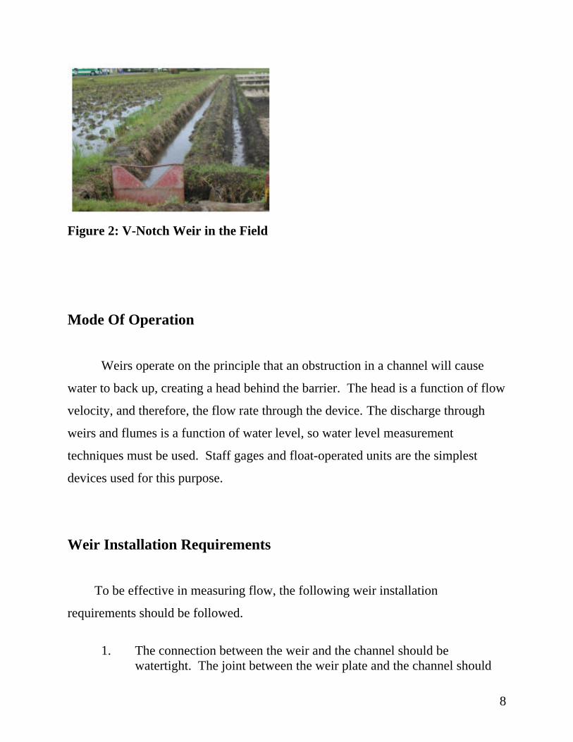
Figure 2: V-Notch Weir in the Field
Mode Of Operation
Weirs operate on the principle that an obstruction in a channel will cause
water to back up, creating a head behind the barrier. The head is a function of flow
velocity, and therefore, the flow rate through the device. The discharge through
weirs and flumes is a function of water level, so water level measurement
techniques must be used. Staff gages and float-operated units are the simplest
devices used for this purpose.
Weir Installation Requirements
To be effective in measuring flow, the following weir installation
requirements should be followed.
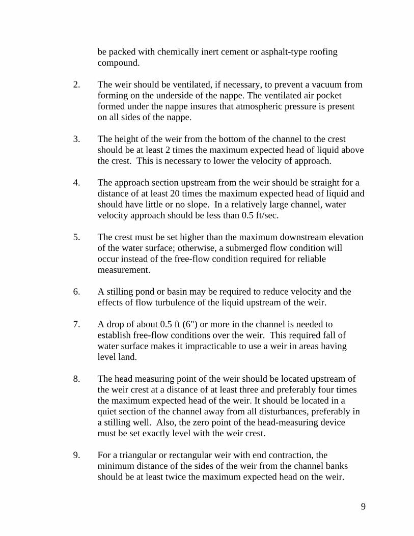
1. The connection between the weir and the channel should be
watertight. The joint between the weir plate and the channel should
9
be packed with chemically inert cement or asphalt-type roofing compound.
2. The weir should be ventilated, if necessary, to prevent a vacuum from
forming on the underside of the nappe. The ventilated air pocket formed under the nappe insures that atmospheric pressure is present on all sides of the nappe.
3. The height of the weir from the bottom of the channel to the crest
should be at least 2 times the maximum expected head of liquid above the crest. This is necessary to lower the velocity of approach.
4. The approach section upstream from the weir should be straight for a
distance of at least 20 times the maximum expected head of liquid and should have little or no slope. In a relatively large channel, water velocity approach should be less than 0.5 ft/sec.
5. The crest must be set higher than the maximum downstream elevation
of the water surface; otherwise, a submerged flow condition will occur instead of the free-flow condition required for reliable measurement.
6. A stilling pond or basin may be required to reduce velocity and the
effects of flow turbulence of the liquid upstream of the weir. 7. A drop of about 0.5 ft (6") or more in the channel is needed to
establish free-flow conditions over the weir. This required fall of water surface makes it impracticable to use a weir in areas having level land.
8. The head measuring point of the weir should be located upstream of
the weir crest at a distance of at least three and preferably four times the maximum expected head of the weir. It should be located in a quiet section of the channel away from all disturbances, preferably in a stilling well. Also, the zero point of the head-measuring device must be set exactly level with the weir crest.
9. For a triangular or rectangular weir with end contraction, the
minimum distance of the sides of the weir from the channel banks should be at least twice the maximum expected head on the weir.
10
10. Avoid deposition of gravel, sand, and silt above the weir so that
accurate water measurements can be obtained.
Requirements For Setting And Operating Weirs
1. The velocity of approach of water should not exceed 15 centimeters per second. This is accomplished by setting the weir at the lower end of a long pool, which is wide and deep enough to give an even, smooth current.
2. The longitudinal axis of the weir should be perpendicular to the direction
of the flow. If a weir box is used, the centerline of the weir box should be parallel to the direction of the flow.
3. The face of the weir should be vertical and at a right angle to the direction
of the flow.
Discharge Computation Procedure Flow rate is determined by measuring the vertical distance (water depth) from
the crest of the overflow part of the weir to the water surface in the upstream pool.
The weir calibration curve then translates this recorded depth into the rate of flow
at the device. Discharge tables for standard measurement devices are readily
available from the online version of the USGS Water Measurement Manual or in
the printed version of the Manual.
Weir Formulas by Weir Type
The most common types of weirs are the rectangular and the triangular (V-
notch) weirs. Each type of weir has an associated equation for determining the
11
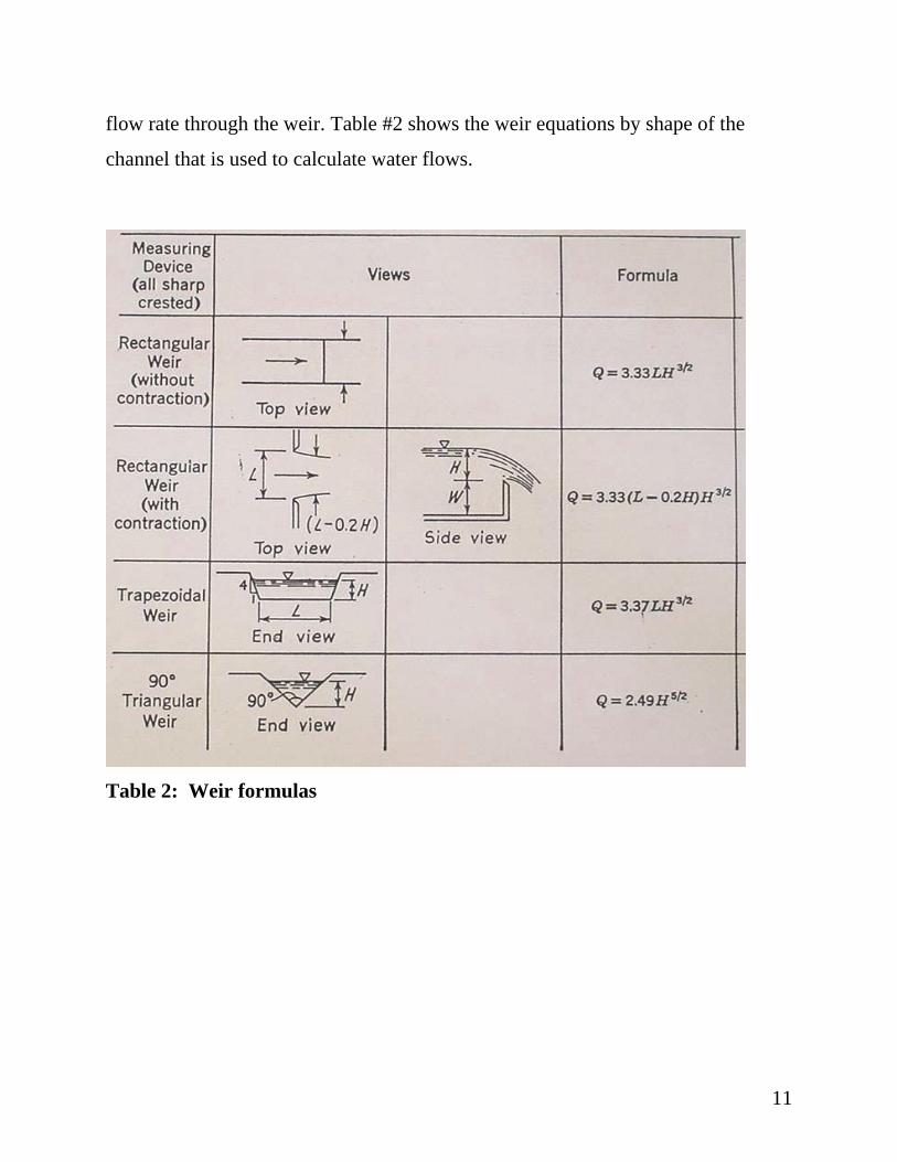
flow rate through the weir. Table #2 shows the weir equations by shape of the
channel that is used to calculate water flows.
Table 2: Weir formulas
12
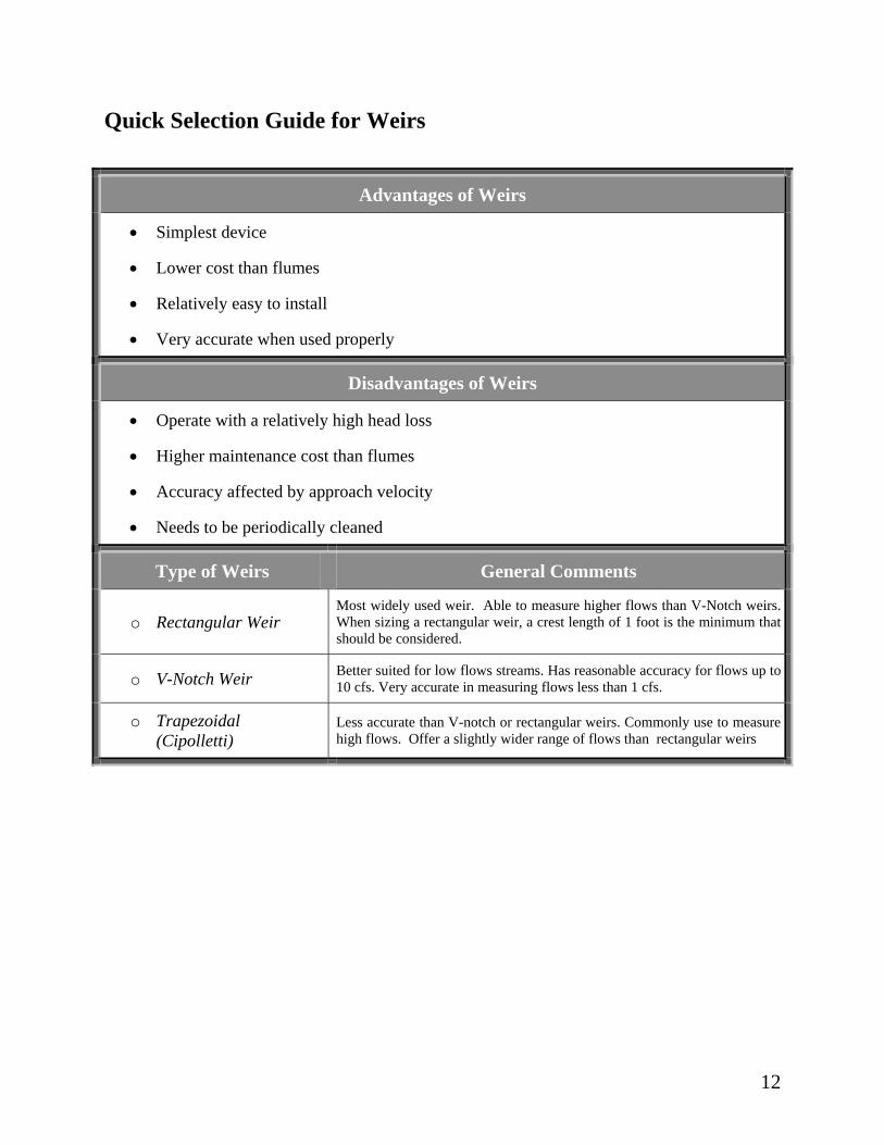
Quick Selection Guide for Weirs
Advantages of Weirs
• Simplest device
• Lower cost than flumes
• Relatively easy to install
• Very accurate when used properly
Disadvantages of Weirs
• Operate with a relatively high head loss
• Higher maintenance cost than flumes
• Accuracy affected by approach velocity
• Needs to be periodically cleaned
Type of Weirs General Comments
o Rectangular Weir Most widely used weir. Able to measure higher flows than V-Notch weirs. When sizing a rectangular weir, a crest length of 1 foot is the minimum that should be considered.
o V-Notch Weir Better suited for low flows streams. Has reasonable accuracy for flows up to 10 cfs. Very accurate in measuring flows less than 1 cfs.
o Trapezoidal (Cipolletti)
Less accurate than V-notch or rectangular weirs. Commonly use to measure high flows. Offer a slightly wider range of flows than rectangular weirs
13
FLUMES
The traditional method of open channel water measurement in agricultural
systems is the flume. Normally, a flume consists of a converging section to restrict
the flow, a throat section with straight parallel sides, and a diverging section to
assure that the downstream level is less than the level in the converging section
(see flume configuration figure). Flumes are designed with the intent of producing
a critical depth in the flume throat and thereby creating a direct relationship
between water depth and flow rate. The head to flow rate relationship of a flume
may be defined by either test data (calibration curves) or by derived empirical
formula based on field research.
Flumes are categorized in two main classes: Long-Throated flumes and
Short-Throated flumes.
Long-Throated Flumes These types of flumes control the discharge in a throat that is long enough to
cause nearly parallel flow lines in the region of flow control. An example of this
type of flume is the modified broad-crested weir also called a ramp flume. Long-
Throated flumes can have nearly any desired cross-sectional shape and can be
custom fitted into most canal site geometry. They perform well in channels with
low gradients and can perform under submerged conditions. The USGS has a free
computer program called Winflume for the design of long-throated flumes. The
software can be downloaded from the following web page address
http://www.usbr.gov/pmts/hydraulics_lab/winflume/.
Although long-throated flumes can be computer recalibrated using as-built

14
dimensions to correct for moderate form slipping or errors of construction,
correcting for throat-section slope in the direction of flow is not always
satisfactory. In any case, adequate care during construction is preferable. The
modified broad-crested weir flume has only one critical flow surface, and it is
level.
Figure 3: Ramp flume
Short-Throated Flumes Short-throated flumes control the discharge rate in a region that produces
curvilinear flow. Although they are considered short, the overall specified length of
the finished structure, including transitions, might be relatively long. The Parshall
flume and the Cutthroat flume are the most common examples of this type of
flume.
The most popular flume designs in use today include the Parshall flume, the
Cutthroat flume, and the Trapezoidal flume. Although Parshall flumes are in
extensive use in many western irrigation projects, they are no longer generally
recommended. The long throated flume is the recommended choice for most

15
projects because of its simple design, easy installation and flexibility in placing
them in complex channel shapes with various flow conditions.
Figure 4: Parshall Flume Configuration Diagrams
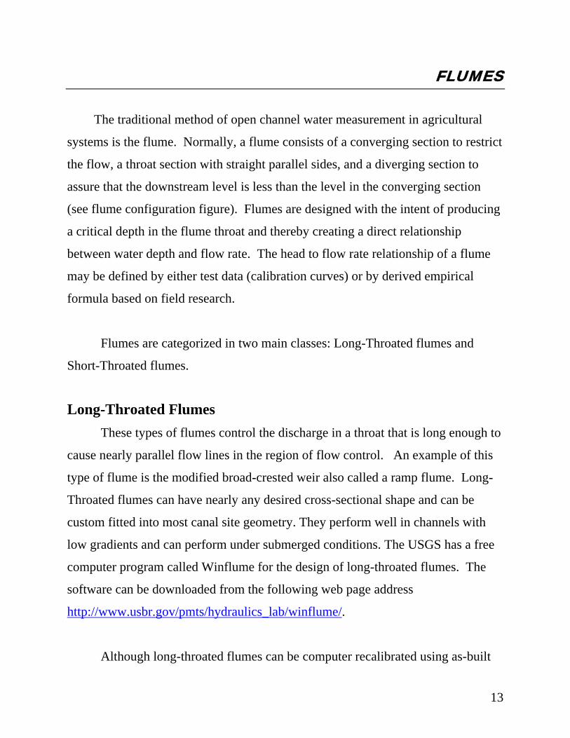
16
Figure 5: Parshall Flume Installed in a Channel
Primary Characteristics Of Flumes
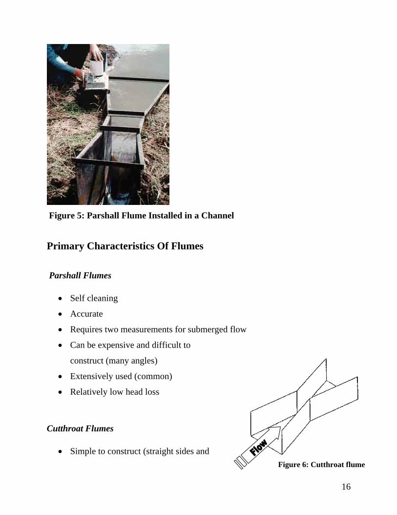
Parshall Flumes
• Self cleaning
• Accurate
• Requires two measurements for submerged flow
• Can be expensive and difficult to
construct (many angles)
Figure 6: Cutthroat flume
• Extensively used (common)
• Relatively low head loss
Cutthroat Flumes
• Simple to construct (straight sides and
17
bottom and simple angles)
• Fairly accurate and easy to calibrate
• Less expensive than Parshall flumes
• Can be constructed of sheet metal or plastic for easy portability
• Can be made in many sizes for measuring flows in large canals, head
ditches, or small furrows
• Head is measured in the upstream section of flume
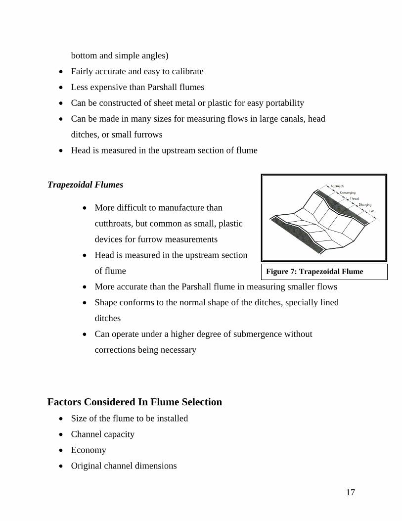
Trapezoidal Flumes
• More difficult to manufacture than
cutthroats, but common as small, plastic
devices for furrow measurements
• Head is measured in the upstream section
of flume
• More accurate than the Parshall flume in measuring smaller flows
Figure 7: Trapezoidal Flume
• Shape conforms to the normal shape of the ditches, specially lined
ditches
• Can operate under a higher degree of submergence without
corrections being necessary
Factors Considered In Flume Selection • Size of the flume to be installed
• Channel capacity
• Economy
• Original channel dimensions

18
Parshall flume sizes are designated by the throat width. Because of the
considerable overlap in flume discharges, it is possible to pass a given discharge
through many different standard size flumes. Therefore, in addition to anticipated
normal and maximum flows, the choice of the proper size should consider other
factors such as throat width, economy, and channel dimensions. In the interest of
economy, the smallest flume of adequate capacity is generally selected. The final
selection is normally made on the basis of the original channel dimensions. For
example, if a 2-foot flume can accommodate the discharge without overrunning the
upstream channel banks or flooding other outlets and facilities, it would be
preferred over a 3 or 4-foot flume. However, when the width of the channel is
considered, it may be just as economical to use a 3 or 4-foot flume because longer
and more costly wing walls may be needed to span the channel when using the
narrower flume. Dimensions are available for flumes with throat width ranging
from 1 inch to 50 feet. The flumes cover a range of discharges from 0.01 to 3000
cfs.
Typical Flume Prices
Cost of Parshall, Cutthroat, Ramp, and Trapezoidal flumes varies
considerable depending on whether the unit was purchase prefabricated, preformed
(which needs assembly prior to installation), or fabricated locally.
Flume Type Cost ($) Preformed Galvanized 2' Parshall 1200 Prefabricated Fiberglass 4' Ramp 1400 - 2400 Concrete or Steel flume fabricated in the field 800 - 1200
Table 3: Prices for various types of flumes

19
Areas You Should Be Concerned With For Successful Installation of A Parshall Flume
1. Upstream conditions: Upstream conditions should promote laminar flow
conditions at the flume inlet. Channel turns, tees, elevation drops or other
obstructions should be avoided. The upstream channel slope should not
allow excessive velocity at the flume. A slope of almost flat to 3%
maximum for very small flumes, and 2% maximum for larger flumes is the
ideal slope value. A 1:4 sloping ramp upstream should be provided for
flumes that must be installed above the channel floor.
2. Crest of the flume: The crest of the flume (the floor of the converging
section where depth measurements are made) must be level both
longitudinally & transversely.
3. Downstream channel: The downstream channel should not permit
submerged conditions to occur. Long, narrow, flat or undersized channels
can result in a backwater effect at the flume and should be avoided. A large
fall or steep slope immediately downstream of the metering station can
eliminate the possibility of submerged flow conditions.
Head Measurement
Flumes use the relationship that a volume of water traveling at a certain speed
will be at a given depth within the flume. Therefore the volume of water
discharged through weirs and flumes is a function of water level, so head
measurement techniques must be used with the equipment to determine flow rates.

20
Staff gages and float-operated units are the simplest devices used for this purpose.
Various electronic sensing, totalizing and recording systems are also available. A
more recent development consists of using ultrasonic pulses to measure liquid
levels by sending sound pulses from a sensor to the surface of the liquid, and
timing the echo return.
Discharge Computation Procedure
Flow rate is determined by measuring the vertical distance (water depth) from
the zero reference at the bottom of the flume to the water surface. The flume
calibration curve or charts then translates this recorded depth into rate of flow at
the device.
Discharge through a Parshall flume can occur for two conditions of flow. The
first, free flow, occurs when there is insufficient backwater depth to reduce the
discharge rate. Under free-flow conditions a phenomenon known as the hydraulic
jump or "Standing Wave" occurs downstream from the flume. Formation of this is
a certain indication of free-flow conditions. The second condition of flow is
submerged flow.
21
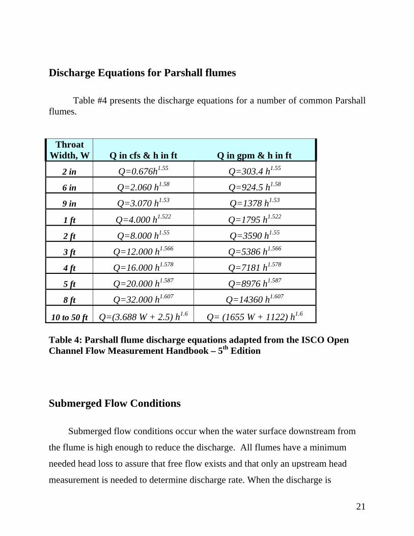
Discharge Equations for Parshall flumes Table #4 presents the discharge equations for a number of common Parshall flumes.
Throat Width, W Q in cfs & h in ft Q in gpm & h in ft
2 in Q=0.676h1.55 Q=303.4 h1.55
6 in Q=2.060 h1.58 Q=924.5 h1.58
9 in Q=3.070 h1.53 Q=1378 h1.53
1 ft Q=4.000 h1.522 Q=1795 h1.522
2 ft Q=8.000 h1.55 Q=3590 h1.55
3 ft Q=12.000 h1.566 Q=5386 h1.566
4 ft Q=16.000 h1.578 Q=7181 h1.578
5 ft Q=20.000 h1.587 Q=8976 h1.587
8 ft Q=32.000 h1.607 Q=14360 h1.607
10 to 50 ft Q=(3.688 W + 2.5) h1.6 Q= (1655 W + 1122) h1.6 Table 4: Parshall flume discharge equations adapted from the ISCO Open Channel Flow Measurement Handbook – 5th Edition Submerged Flow Conditions
Submerged flow conditions occur when the water surface downstream from
the flume is high enough to reduce the discharge. All flumes have a minimum
needed head loss to assure that free flow exists and that only an upstream head
measurement is needed to determine discharge rate. When the discharge is

22
increased above a critical value (submergence limit), the resistance to flow in the
downstream channel becomes sufficient to reduce the velocity, increase the flow
depth, and cause a backwater effect at the flume. In order to determine the
discharge, submerged flow requires the measurement of an upstream depth,
Ha, and a depth in the throat, Hb. The ratio of the downstream depth to the
upstream depth, Ha / Hb, expressed as a percentage, is referred as the submergence
ratio. Ha (upstream water level) is measured at a point 2/3 of the length of the
converging section upstream from the throat entrance). For flume sizes 6-inch to
8-foot, Hb is measured at a point 2 inches upstream from the low point in the floor
of the throat section and 3 inches above it. Calibration tests show that a Parshall
flume is operating under free-flow conditions when the submergence ratio does not
exceed the following submergence ratios:
• 50 percent for flumes 1, 2, and 3 inches wide
• 60 percent for flumes 6 and 9 inches wide
• 70 percent for flumes 1 to 8 feet wide
• 80 percent for flumes 8 to 50 feet wide
When the submergence ratio exceeds the values listed above, the flume is
operating under submerged conditions, and submerged discharge tables will have
to be used to calculate the discharge. In general, selecting and installing a Parshall
flume so that conditions of free flow exist is desired, since submerged conditions
greatly complicate the determination of flow rate.
The discharge (head vs. flow rate) relationship for a Parshall flume with
submergence ratios (Hb / Ha ) of up to 0.7 is given by the following equation.
Q = KW(Ha)n n = 1.522(W)0.026
23
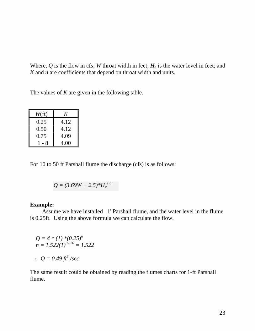
Where, Q is the flow in cfs; W throat width in feet; Ha is the water level in feet; and K and n are coefficients that depend on throat width and units. The values of K are given in the following table.
W(ft) K 0.25 4.12 0.50 4.12 0.75 4.09
1 - 8 4.00 For 10 to 50 ft Parshall flume the discharge (cfs) is as follows: Q = (3.69W + 2.5)*Ha
1.6 Example: Assume we have installed 1' Parshall flume, and the water level in the flume is 0.25ft. Using the above formula we can calculate the flow. Q = 4 * (1) *(0.25)n n = 1.522(1)0.026 = 1.522 ˆ Q = 0.49 ft3 /sec The same result could be obtained by reading the flumes charts for 1-ft Parshall flume.
24
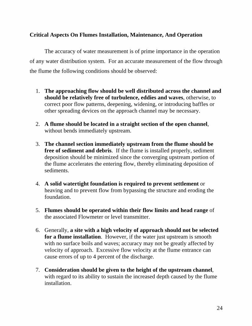
Critical Aspects On Flumes Installation, Maintenance, And Operation
The accuracy of water measurement is of prime importance in the operation
of any water distribution system. For an accurate measurement of the flow through
the flume the following conditions should be observed:
1. The approaching flow should be well distributed across the channel and should be relatively free of turbulence, eddies and waves, otherwise, to correct poor flow patterns, deepening, widening, or introducing baffles or other spreading devices on the approach channel may be necessary.
2. A flume should be located in a straight section of the open channel,
without bends immediately upstream.
3. The channel section immediately upstream from the flume should be free of sediment and debris. If the flume is installed properly, sediment deposition should be minimized since the converging upstream portion of the flume accelerates the entering flow, thereby eliminating deposition of sediments.
4. A solid watertight foundation is required to prevent settlement or
heaving and to prevent flow from bypassing the structure and eroding the foundation.
5. Flumes should be operated within their flow limits and head range of
the associated Flowmeter or level transmitter. 6. Generally, a site with a high velocity of approach should not be selected
for a flume installation. However, if the water just upstream is smooth with no surface boils and waves; accuracy may not be greatly affected by velocity of approach. Excessive flow velocity at the flume entrance can cause errors of up to 4 percent of the discharge.
7. Consideration should be given to the height of the upstream channel,
with regard to its ability to sustain the increased depth caused by the flume installation.
25
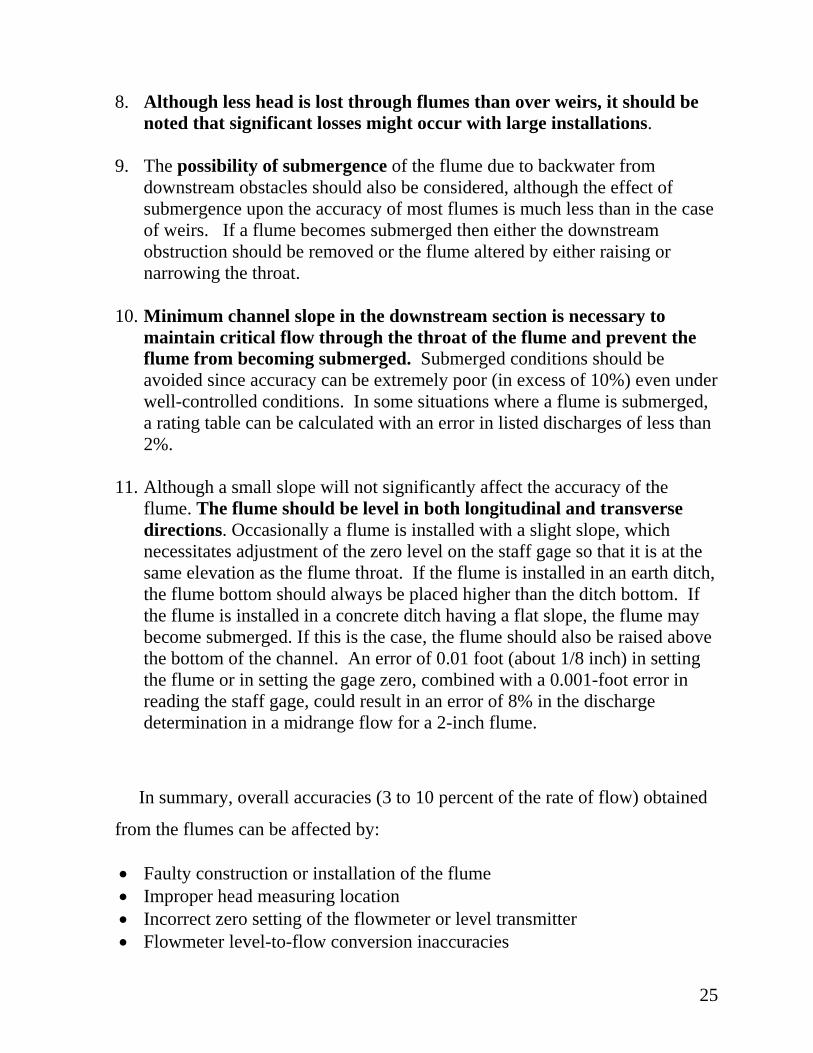
8. Although less head is lost through flumes than over weirs, it should be noted that significant losses might occur with large installations.
9. The possibility of submergence of the flume due to backwater from
downstream obstacles should also be considered, although the effect of submergence upon the accuracy of most flumes is much less than in the case of weirs. If a flume becomes submerged then either the downstream obstruction should be removed or the flume altered by either raising or narrowing the throat.
10. Minimum channel slope in the downstream section is necessary to
maintain critical flow through the throat of the flume and prevent the flume from becoming submerged. Submerged conditions should be avoided since accuracy can be extremely poor (in excess of 10%) even under well-controlled conditions. In some situations where a flume is submerged, a rating table can be calculated with an error in listed discharges of less than 2%.
11. Although a small slope will not significantly affect the accuracy of the
flume. The flume should be level in both longitudinal and transverse directions. Occasionally a flume is installed with a slight slope, which necessitates adjustment of the zero level on the staff gage so that it is at the same elevation as the flume throat. If the flume is installed in an earth ditch, the flume bottom should always be placed higher than the ditch bottom. If the flume is installed in a concrete ditch having a flat slope, the flume may become submerged. If this is the case, the flume should also be raised above the bottom of the channel. An error of 0.01 foot (about 1/8 inch) in setting the flume or in setting the gage zero, combined with a 0.001-foot error in reading the staff gage, could result in an error of 8% in the discharge determination in a midrange flow for a 2-inch flume.
In summary, overall accuracies (3 to 10 percent of the rate of flow) obtained
from the flumes can be affected by:
• Faulty construction or installation of the flume • Improper head measuring location • Incorrect zero setting of the flowmeter or level transmitter • Flowmeter level-to-flow conversion inaccuracies

26
• Use of the flume outside of its proper range • Improper installation or maintenance of the flume • Turbulence surges in the approach channel • Poor exit conditions
Even under the most favorable circumstances, measurement of water
quantities is subject to some error. Those errors should and can be kept to a
minimum with a sound program for calibrating, maintaining, and by recalibrating
all water measuring devices on a regular basis.
Maintenance of Parshall flumes consists principally of keeping them free of
debris and algae. In some cases, it is necessary to erect a shade over the flume
throat to discourage algae growth. Copper-based paints are available to assist in
keeping algae from adhering to the throat area. Periodically, flumes should be
checked to verify that the flume structure is level to ensure accurate flow reading.
The head or level transmitter should be periodically inspected for proper
calibration or to assure that the zero reference is at the same elevation of the throat
section.
L Make sure that the level-to-flow rate conversion table matches the flume
being used and that the desired units of measure for flow rate and total flow
have been selected.

27
Instruction For Placing Flumes
1. Locate the high water line on ditch bank where the flume is to be
installed.
2. Select from capacity or discharge curves the proper depth of water or
head (Ha) that corresponds with the maximum capacity of the ditch.
For example assume that a 1-foot flume is to be used and that the
maximum discharge is 4.0 cfs; therefore, the depth of water on the
crest Ha is 1.0 foot.
3. Place the floor of the flume at a depth not more than 70% of Ha below
the high water line. In general, the floor of the flume should be placed
as high in the ditch as the grade and other conditions permit. For
example, allow 70% submergence, then 0.7 x 1.0 = 0.7 feet.
Therefore, set the flume crest no more than 0.7 feet below the high
water mark. The loss of head will be 1 feet minus 0.7 feet = 0.3 feet.

28
Quick Selection Guide For Flumes
Advantages of Flumes
• Self-cleaning to a certain degree
• Relatively low head loss
• Accuracy less affected by approach velocity than weirs
• Lower maintenance cost than weirs
Disadvantages of Flumes
• High cost
• Difficult to install
Type of Flume General Comments
o Parshall Flume Most widely known and used flume for permanent installations. Available in throat widths ranging from 1” to 50ft to cover most flows. Fairly difficult installation requiring a drop in the conduit invert.
o Cutthroat Flume Similar to Parshall flume, except that flat bottom does not require drop in conduit invert. Can function well with high degree of submergence. Flat bottom passes solids better than Parshall flume.
o Trapezoidal Flume Developed to measure flows in irrigation channels. Principal advantage is ability to measure wide range of flows and also maintain good accuracy at low flows.
29
REFERENCES Bureau of Reclamation, 2001. Water Measurement Manual. 3rd ed., revised reprint, U.S. Government Printing Office, Washington DC, 20402.
http://www.usbr.gov/pmts/hydraulics_lab/pubs/wmm/index.htm Clemmens, A.J.; Wahl T.L.; Bos, M.G., and Replogle, J.A. 2001.
Water Measurement With Flumes And Weirs . ILRI Publication 58. Grant, D. M. and Dawson, B. D. ISCO Inc. Open Channel Flow Measurement Handbook, 5th Edition, 1998. Hansen, Vaughn E., et. al. (1980). Irrigation Principles and Practices, Fourth ed.
John Wiley & Sons Inc. Spitzer, D.W, editor. ISA. Flow Measurement: Practical Guides for Measurement and Control. 1991.