flexible amperometric biosensor for sweat lactate...
TRANSCRIPT
Flexible Amperometric Biosensor for Sweat
Lactate Detection
by
Md Abu Abrar
B.Sc., Bangladesh University of Engineering and Technology, 2013
Thesis Submitted in Partial Fulfillment of the
Requirements for the Degree of
Master of Applied Science
in the
School of Mechatronic Systems Engineering
Faculty of Applied Science
Md Abu Abrar 2016
SIMON FRASER UNIVERSITY
Summer 2016

ii
Approval
Name: Md Abu Abrar
Degree: Master of Applied Science
Title: Flexible Amperometric Biosensor for Sweat Lactate Detection
Examining Committee: Chair: Kevin Oldknow Lecturer
Woo Soo Kim Senior Supervisor Assistant Professor
Erik Kjeang Supervisor Associate Professor
Jiacheng (Jason) Wang Internal Examiner Assistant Professor
Date Defended/Approved: August 16, 2016

iii
Abstract
A flexible amperometric biosensor using silver nanoparticle-based conductive electrode
was fabricated for sweat lactate measurement. The developed sensor was composed of
three-electrode configuration for the demonstration of electro-chemical sensing with silver
nanoparticles as a single electrode material. Thin-film electrodes with cross-serpentine
pattern have been demonstrated to be highly flexible without significant change in their
electrical behavior. Fabricated electrodes were annealed for higher conductivity and
modified for electrochemical analysis of lactate. The permselective membrane on working
electrode was used to enhance selectivity of the sensor against common interfering
electroactive anions such as ascorbate. Enzyme was immobilized on the sensor surface
for lactate oxidization to produce hydrogen peroxide. The optimum potential (0.65 V) was
determined employing cyclic voltammetry and applied for different in-vitro experiments to
generate current flow- proportional to lactate concentration. Bleach-assisted-modified in-
sensor pseudo reference electrode evinces its long term potential stability against
standard commercial reference electrode. The catalytic response of the sensor shows
excellent linear behavior between 0~25 mM of lactate. This noninvasive electrochemical
lactate sensor also demonstrates excellent behavior to reject anionic interference,
resiliency against mechanical deformation and temperature fluctuation which leads to the
possibility of using it on human epidermis for continuous measurement of lactate from
sweat. Finally, the wireless data transmission using near-field-communication unit is
demonstrated for the realization of a practical sensor application to be able to measure
sweat lactate portably using human perspiration.
Keywords: Lactate; Silver Nanoparticles; Stamping; Enzyme immobilization; Cross-serpentine pattern; Cyclic voltammetry

iv
Dedication
To the Almighty God who created, taught by pen-
taught man that which he knew not

v
Acknowledgements
I would like to express my sincere gratitude to my senior supervisor Dr. Woo Soo
Kim, whose door was always wide open whenever I bogged down while going through my
research and writing my dissertation. His expertise, knowledge and skills added
considerably to my graduate life and his patient instruction helped me steer in the right
direction. I would also like to thank other members of my thesis committee: Dr. Erik Kjeang,
Dr. Jiacheng (Jason) Wang and Dr. Kevin Oldknow.
My sincere thanks also goes to the staff of SFU MSE, whose arduous work keeps
the program running, especially to Jennifer Coffey, who was always there to help me,
never frowned although I probably gave a lot of reasons to. I would like to thank Khadijah
Ali for lending her kind hand during experiments in the chemistry lab.
I appreciate all the efforts my fellow lab members put to create a jovial environment
in the lab and it was always fun to have conversations, working and hanging out with them.
This is where a made some of my best friends. I am really grateful for all the help they
offered me from time to time. I would like to express my heartfelt gratitude to Yue Dong
for his kind help to design, experiment and take care of the wireless transmission unit of
the sensor.

vi
Table of Contents
Approval .......................................................................................................................... ii Abstract .......................................................................................................................... iii Dedication ...................................................................................................................... iv Acknowledgements ......................................................................................................... v Table of Contents ........................................................................................................... vi List of Tables ................................................................................................................. viii List of Figures................................................................................................................. ix List of Equations ............................................................................................................. xi List of Acronyms ............................................................................................................ xii
Chapter 1. Introduction ............................................................................................. 1 1.1. Objective ................................................................................................................ 1 1.2. Contribution ............................................................................................................ 2 1.3. Thesis Organization ................................................................................................ 2 1.4. Background ............................................................................................................ 3
1.4.1. Lactate Production and Non-invasive Lactate Sensing .............................. 3 1.4.2. Amperometry and Principle of Lactate Sensing ......................................... 6 1.4.3. Stretchable Electrode .............................................................................. 12 1.4.4. Conductive Nano-materials for Lactate Sensors ...................................... 15
Chapter 2. Fabrication of Silver Nanoparticle-based Electrode ........................... 18 2.1. Introduction ........................................................................................................... 18 2.2. Electrode Fabrication ............................................................................................ 18
2.2.1. Synthesis of Silver Nanoparticles ............................................................ 18 2.2.2. Pattern Transfer ....................................................................................... 19
2.3. Characterization of Fabricated Electrodes ............................................................ 20 2.3.1. Cross-serpentine Pattern ......................................................................... 20 2.3.2. Mechanical Properties of Stamped Electrodes ........................................ 22
Chapter 3. Modification of Electrodes for Sweat Lactate Sensor ......................... 25 3.1. Working Electrode Modification ............................................................................ 25
3.1.1. Anionic Polymer ....................................................................................... 25 3.1.2. Nafion as Anionic Polymer ....................................................................... 26 3.1.3. Cellulose Acetate as Anionic Polymer ..................................................... 28 3.1.4. Enzyme Immobilization ............................................................................ 31
3.2. Reference Electrode Modification and Optimization .............................................. 35 3.2.1. Chloridization ........................................................................................... 35 3.2.2. Characterization of Ag/AgCl Electrode ..................................................... 36 3.2.3. Stability of Reference Electrode ............................................................... 39
Chapter 4. Characterization and Analysis of Fabricated Lactate Sensor ............ 41 4.1. In-vitro Experiment ............................................................................................... 41
4.1.1. Cyclic Voltammetry for Redox Analysis ................................................... 41

vii
4.1.2. Amperomtric i-t curve and calibration ....................................................... 43 4.2. Interference Study ................................................................................................ 45
4.2.1. Interferences in Human Perspiration ........................................................ 45 4.2.2. Sensor Interference Test ......................................................................... 45
4.3. Stability in Aberrations .......................................................................................... 47 4.3.1. Temperature Dependence ....................................................................... 47 4.3.2. Bending Test ........................................................................................... 48
4.4. Wireless Transmission of Sensor Response ......................................................... 49
Chapter 5. Conclusion and Future Works .............................................................. 52 5.1. Conclusion ............................................................................................................ 52 5.2. Future Works ........................................................................................................ 53
References ................................................................................................................ 55 Appendix A. EDS spectra of unchloridized and chloridized electrodes ......................... 70 Appendix B. Potential stability test for unchloridized and chloridized electrodes ........... 71

viii
List of Tables
Table 3.1. Performance with different interference rejection membranes ................ 30
Table 3.2. Chemical Composition of Ag and Cl in different AgNP-electrodes .......... 39

ix
List of Figures
Figure 1.1. Structure of lactic acid and lactate[2] ........................................................ 3
Figure 1.2. Lactate production during anaerobic process ........................................... 4
Figure 1.3. Basic two-electrode setup of amperometry ............................................... 7
Figure 1.4. Illustration of forced redox reaction........................................................... 9
Figure 1.5. Purpose of employing reference electrode (RE) ..................................... 10
Figure 1.6. Schematic of a Ag/AgCl reference electrode[40] .................................... 11
Figure 1.7. Melting temperature of gold nanoparticles with different size[57] ............ 14
Figure 1.8. Schematic representations for different fabrication techniques using silver nano-ink[52] ......................................................................... 15
Figure 2.1. Schematic models for electrode-to-skin interface[41] ............................. 20
Figure 2.2. Stretching behavior of electrodes[41] ..................................................... 21
Figure 2.3. AFM images of stamped AgNP-electrodes subjected to stretching[79] ......................................................................................... 23
Figure 3.1. AFM image of dropcasted and air-dried Nafion layer .............................. 27
Figure 3.2. AFM image of dropcasted and air-dried cellulose acetate layer .............. 28
Figure 3.3. Sensor response to lactate with cellulose acetate membrane ................ 29
Figure 3.4. Sensor response to interference with cellulose acetate membrane ........ 30
Figure 3.5. Illustration of immobilized enzyme[102] .................................................. 31
Figure 3.6. Glutaraldehyde assisted cross-linking of enzyme[131] ........................... 33
Figure 3.7. Enzyme immobilization using BSA and GA ............................................ 34
Figure 3.8. UV-Vis spectra of AgNPs and Chloridized AgNPs .................................. 37
Figure 3.9. lactate sensor with different functional layers ......................................... 38
Figure 3.10. Surface morphology of stamped electrodes ........................................... 38
Figure 3.11. Potential stability test of different chloridized samples with saturated KCl ......................................................................................... 40
Figure 4.1. Cyclic Voltammetric excitation signal ...................................................... 41
Figure 4.2. Cyclic Voltammogram of 10 mM lactate vs Ag/AgCl ............................... 42
Figure 4.3. Amperometric i-t curve at 0.65 V Vs Ag/AgCl ......................................... 44
Figure 4.4. Calibration of sensor responses for different lactate concentrations ....... 44
Figure 4.5. Sensitivity of the lactate sensor towards ascorbic acid (AA) ................... 46
Figure 4.6. Selectivity test of the sensor (0.65 Vs Ag/AgCl) ..................................... 46
Figure 4.7. Thermal stability of the lactate sensor .................................................... 47

x
Figure 4.8. Response of the lactate sensor vs bending curvature ............................ 48
Figure 4.9. Wireless transmission scheme for the lactate sensor ............................. 50
Figure 4.10. Wireless transmission system of the sensor ........................................... 51

xi
List of Equations
Equation 1: Energy production in glycolysis…………………………………………. 4
Equation 2: LOD enzyme catalyses lactate oxidization…………………………….. 8
Equation 3: Oxidization of reduced enzyme…………………………………………. 8
Equation 4: Oxidization of hydrogen peroxide……………………………………….. 8
Equation 5: Reaction at Ag/AgCl reference electrode………………………………. 12
Equation 6: Conductivity of material………………………………………………….. 22
Equation 7: Bending stiffness of beam……………………………………………….. 22
Equation 8: Bending stiffness for beam with rectangular cross section…………… 22
Equation 9: Reduction of hydrogen peroxide………………………………………… 43
xii
List of Acronyms
ADP Adenosine diphosphate
AgNP Silver Nanoparticle
AgNW Silver Nanowire
ATP Adenosine triphosphate
AuNP Gold Nanoparticle
BSA Bovine Serum Albumin
CE Counter Electrode
CoA Coenzyme A
CV Cyclic Voltammetry
EDS Energy-dispersive X-ray Spectroscopy
GA Glutaraldehyde
GCE Glassy Carbon Electrode
LDH Lactate dehydrogenase
LOD Lactate oxidase
MWCNT Multi-wall Carbon Nanotube
NADH Nicotinamide adenine dinucleotide
N-CNT Nitrogen-doped Carbon Nanotube
NHE Normal Hydrogen Electrode
PB Prussian Blue
PBS Phosphate Buffer Saline
PDMS Polydimethylsiloxane
PET Polyethylene terephthalate
Pi Orthophosphate group
PU Polyurethane
RE Reference Electrode
SCE Saturated Calomel Electrode
SEM Scanning electrode microscope
SWNT Single-walled Carbon Nanotube
TNT Titanium Nanotube
UV-Vis Ultraviolet-visible spectrophotometry
WE Working Electrode

1
Chapter 1. Introduction
1.1. Objective
This research project aims towards development of a flexible amperometric
biosensor based on silver nanoparticles for monitoring lactate concentration utilizing
perspiration. The electrode pattern will facilitate higher conformability for the sensor to be
wearable and also improve the bendability. The objectives of this project are as follows:
1. To develop and characterize a flexible sensing platform on thin substrate.
2. To utilize easy stamping and spraying method to fabricate electrodes and
characterize the sprayed, stamped, annealed electrodes.
3. To demonstrate and improve biosensing technology for lactate measurement
and quantification of lactate in human perspiration at physiological level (0-25
mM).
4. To propose and demonstrate an immobilization procedure of enzyme.
5. To develop a flexible electrode design for high conformability, low impedance
and bendability.
6. To develop a sensing platform to reduce the contribution from interferences.
7. To fabricate and incorporate in-sensor reference electrode with long-term
stability.

2
1.2. Contribution
With this work, Stretchable Devices Laboratory (SDL) at Simon Fraser University
auspicates its research in electrochemical sensing and expands its scope in design,
fabrication and application of silver nanoparticle-based bendable electrodes. This work
also has laid foundation for further improvement in enzyme immobilization, optimization of
anti-interference agents, incorporating stretchable substrate for lactate sensing. Although
the sensor could not be able to make its way to be tested on actual human body due to
time constraint, successful in-vitro quantification of lactate on bendable substrate was
demonstrated. Portion of this work was presented at joint MSE-SIAT research
showcase/conference on May 3rd, 2016 as “Bendable Electro-chemical Lactate Sensor
Printed with Silver Nanoparticles”. This work has also been published in Scientific Reports-
Nature Publishing Group: Abrar, M. A. et al. Bendable Electro-chemical Lactate Sensor
Printed with Silver Nano-particles. Sci. Rep. 6, 30565; doi: 10.1038/srep30565 (2016).
1.3. Thesis Organization
There are five chapters in this thesis with 2, 3 and 4 being related to the
experiments and work done during last two years for Master’s degree. First chapter deals
with the brief description of lactate, importance of its measurement, general amperometric
sensing principle, the need for stretchable electrode and conductive nanomaterials as
sensing platform. Chapter 2 is the description of the design considered and steps followed
to synthesize silver nanoparticles and fabricated stretchable electrode for the biosensor.
It also depicts the mechanical properties of stamped cross-serpentine-shaped electrodes.
Chapter 3 focuses on the modification of different electrodes. It articulates the reasons
behind using different materials with their functionin the electrochemical lactate sensor.
This chapter also describes preparation of the material and incorporating them with the
sensor. Different in-vitro experiments are described in chapter 4. It covers all the
experiments: cyclic voltammetry for detecting optimum potential, amperometric i-t curve,
and calibration of the sensor, interference and stability tests. Finally chapter 5 draws a
summary of this work and provides insights into what steps to follow for future opportunity
for further improvement of the sensor.

3
1.4. Background
1.4.1. Lactate Production and Non-invasive Lactate Sensing
Lactate is the conjugate base of lactic acid (CH3CH(OH)CO2H), otherwise known
as 2-hydroxypropanoic acid. Being produced continuously from pyruvate, lactate plays a
cardinal role in several animal biochemical processes. In solution, lactic acid gives up its
proton and its conjugate base lactate surfaces (Figure 1). Its pKa is 3.86[1], which makes
it to deprotonate ten times more easily than acetic acid. Lactic acid could stay in two optical
isomers- L (+) and D (-) lactic acids. L-lactate is natural product of anaerobic metabolism
and present in the human body.
Figure 1.1. Structure of lactic acid and lactate[2]
Energy needed for our body is always produced due to a metabolic pathway known
as glycolysis. This pathway beaks down glycogen and feeds the body necessary energy
in the form of Adenosine triphosphate (ATP). ATP is constantly produced from pyruvate
with sufficient oxygen supply according to Kerbs cycle[3]. Reactions occur in catabolic
processes extract their energy from fat and carbohydrate as fuel source and the energy is
later converted into ATP through oxidations and reductions[4]. In glycolysis, each
molecule of glucose breaks down to two smaller molecules of pyruvates and two ATPs
4
following several steps and each step is catalyzed by a different enzyme. Adenosine
diphosphate (ADP) is converted to ATP with the help of an Orthophosphate group (Pi) and
NAD+ cofactor is reduced to NADH. The net reaction could be summarized as[5]:
6 12 6
2
2 2 2
2 2 2 2
C H O NAD ADP Pi
Pyruvate ATP NADH H H O
(1)
This process does not yield much of energy and is regarded as energetically
unfavorable[6]. Pyruvate produced in glycolysis then enters cell mitochondria, gets
converted into Acetyl CoA and begins Krebs cycle to produce approximately 30 molecules
of ATP[4]. In aerobic process, molecular oxygen completely oxidizes pyruvate to CO2 and
H2O.
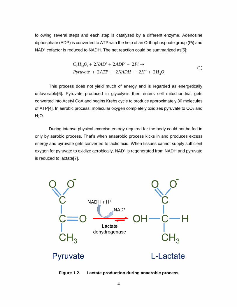
During intense physical exercise energy required for the body could not be fed in
only by aerobic process. That’s when anaerobic process kicks in and produces excess
energy and pyruvate gets converted to lactic acid. When tissues cannot supply sufficient
oxygen for pyruvate to oxidize aerobically, NAD+ is regenerated from NADH and pyruvate
is reduced to lactate[7].
Figure 1.2. Lactate production during anaerobic process

5
Lactate produced after glycolysis diffuses from muscle cells to bloodstream
causing synthesis of ATP in the absence of oxygen and facilitates lactate transport to other
well-oxygenated cells of tissue. Lactate recycles back to pyruvate in these cells and to
glucose in liver[4] balancing lactate level in body. But if the production rate of lactate is
much larger than its removal rate (during strenuous muscle contraction), it will lead to build
up proton concentration inside the cells which is referred as ‘lactic acidosis’[8].
Physical conditions leading to lactic acidosis could potentially lead to inimical
health consequences. Respiratory failure[9], liver diseases[10], tissue hypoxia[11],
cardiogenic[12] or endotoxic shocks could increase lactate concentration. In cancer cells,
even under aerobic condition glycolysis could bump up which is known as Warburg
Effect[13] which will eventually increase the lactate level. According to researchers, this
may have some effect on tumor proliferation and invasion, providing tumor cell competitive
advantages[14]. Hence lactate concentration could be used as an excellent biomarker for
general clinical diagnosis purposes and also for patients at intensive care units.
It is very common scenario for hospitalized patients to develop muscle sore due to
prolonged confinement to bed or wheelchair. Upon compression for a long time, there is
a decrease in oxygen and glucose in tissue and it forces the cells to call for anaerobic
metabolism. This way cells tend to use up their glucose reserve and starts accreting
lactate[15]. Rise in lactate concentration beyond threshold or too low glucose
concentration could cause cell death[16].
It is thus of utmost importance to continuously measure lactate concentration in
human body. Lactate concentration in healthy person could vary from 0.6 mM to 2 mM at
resting conditions[8] and arduous physical activity could rise it up to 10 mM[17].
Commercially available lactate sensors usually depends on drawing blood using
fingerpricks which is extremely inconvenient for incessant measurement and it also
inherently possesses its drawbacks being invasive. Piercing body to collect blood to
measure lactate creates additional stress on patient which has been proved to rise lactate
level and eventually convey misleading information[18].
Quest for noninvasive and continuous lactate monitoring led researches to search
for utilizing alternative body fluids. Anaerobic metabolism of glucose takes place in tissues

6
with high glycolysis rate such as muscle (25%), skin (25%), brain (20%), red blood cells
(20%) and intestine (10%)[19]. Hence lactate could be found in body fluids such as
saliva[20], interstitial fluids[21], tear[22] and exhaled breath[23]. Lactate could as well be
found in urine[24] and sweat, secreted by eccrine gland[25].
Sweat demonstrates a great prospect for continuous lactate measurement being
easily accessible to offer real-time physiological information[26]. Sweat is composed of
various dissolved salts, lactate, urea, amino acids, bicarbonate etc[27]. Human
perspiration has been estimated to contain at least 61 different constituents with varying
concentrations[28] [29]. Sweat is secreted by two different types of glands namely eccrine
and apocrine glands. Eccrine gland plays a vital role in body thermoregulation and
electrolyte excretion[30]. During normal metabolism, eccrine sweat gland obtains ATP
through oxidative phosphorylation. Under conditions such as ischemia or anaerobic
metabolism, glycolysis becomes the main pathway to produce ATP and gives rise to
lactate[30]. Intensive exercise ends up leading to increase in lactate production in sweat
from ~10 mM to as high as ~25 mM[31].
Not a lot of research has been conducted yet for sweat lactate applications. Sports
science has recently drawn immense attention as it has been shown that lactate plays a
vital role in endurance based activities where anaerobic metabolism is often called for[32].
Sweat lactate could be used as an excellent warning indicator for early detection of
pressure ischemia[33]. Other potential use of sweat lactate could be as biomarker for
diagnosis of cystic fibrosis[34], panic disorder[35] and Frey’s Syndrome[36]. Besides,
there is strong relationship between active muscle and sweat lactate[17]. Human sweat
thus could be successfully employed as an excellent analyte for noninvasive and
continuous lactate measurement[37].
1.4.2. Amperometry and Principle of Lactate Sensing
Amperometry in biosensor is the study of the current response or change in current
response based on analyte concentration when a potential is applied. For ion detections,
amperometry could be defined as change in current response due to presence of ions in
the solution. Either way, it’s the change in current response when a fixed potential is

7
applied. On the contrary, voltammetry is electrochemical technique to study current
response as a function of applied voltage to electrolytic cell; or in simple words- current
response at varying potential. In general, amperometry is the measurement of electrode
current between a pair of electrodes that are driving an electrolysis reaction. In this
reaction one of the reactants is the intended analyte and the measured current is
proportional to the concentration of the analyte.
Figure 1.3. Basic two-electrode setup of amperometry
Figure 1.3 illustrates a typical setup for what the way amperometric sensors would
be working. Two electrodes are put in a solution of analyte with an unknown concentration.
Because of either oxidation reaction happening on anode or reduction reaction happening
on cathode when a potential is applied between the electrodes, there is going to be
electron flow through the wire and pass through the ammeter. As the amount of electron

8
flown (current flow) is now known and as it is proportional to the analyte concentration that
had taken part in the reaction, we could easily figure out the concentration of analyte.
There could be two (working and counter) or three electrodes (working, counter
and reference) in amperometric biosensors. Electron flows between working electrode and
counter electron. The electrochemical reaction takes place in working electrode.
Enzymes are widely used to convert analytes into sensing element. Three different
enzymes are used in amperometric lactate sensors- lactate dehydrogenase (LDH),
cytochrome dependent lactate dehydrogenase and Lactate Oxidase (LOD). Using LDH
requires presence of a cofactor such as NAD+ which is an inherent disadvantage.
Presence of a cofactor requires an additional immobilization step. LDH-based sensors
show lower sensitivity for detecting lactate at low concentration range[38]. Cytochrome
based lactate dehydrogenase does not require external cofactors. However it has its own
disadvantages such as the need for analyte dilution. High lactate concentration such as in
blood and sweat tends to saturate the enzyme. If this enzyme is used for lactate sensing,
D-lactate could inhibit the oxidation of L-lactate. Pyruvate, a product from the reaction also
shows tendency to inhibit oxidized enzyme at low concentrations[39].
Lactate oxidase (LOD) enzyme is widely used for lactate measurement due to its
reaction simplicity and easy biosensor design. As the name suggests, Lactate Oxidase
(LOD) is an enzyme which catalyzes lactate by oxidation to produce pyruvate just like the
way glucose oxidase oxidizes glucose. The enzyme can be reoxidized in the presence of
O2 to release hydrogen peroxide (H2O2). H2O2 gets oxidized at electrode surface, restores
O2 concentration and gives a current proportional to the amount of lactate. Reactions
involved in LOD-based sensor could be summarized as[8]:
ox redL lactate LOD pyruvate LOD (2)
2 2 2 red oxLOD O LOD H O (3)
2 2 2 2 2H O O H e (4)

9
Spontaneity of a reaction depends on the oxidation potential of the elements
involved in the reaction. Metals with higher oxidation potential has the tendency to release
its electrons when there is a metal with lower oxidation potential to accept the electrons.
For example, let’s paint a picture of Zn immersed in Cu2SO4 solution. Being a metal with
higher oxidation potential Zn will tend to be oxidized to Zn2+ and lower oxidation potential
Cu2+ from the solution will be reduced to Cu due to its higher affinity for electrons. We can
easily measure the net current flow using an ammeter and salt bridge without using any
external applied potential.
When the difference of oxidation potential between two molecules is very low,
giving up and accepting electrons between the molecules would not be as easy although
there is a net desire for electron flow. The molecules here are not capable enough to
initiate the redox reaction by themselves. In this case if we apply a positive bias to the
molecule with higher oxidation potential, it will facilitate the electron flow. This is the reason
why amperometric biosensors are often in need of a small potential supply (Figure 1.3).
Figure 1.4 below demonstrates the scheme of a forced redox reaction.
Figure 1.4. Illustration of forced redox reaction
(A) No electron transfer due to low oxidation potential difference (B) Bias voltage facilitates electron transfer and redox reaction

10
The bias voltage is applied between the working electrode (WE) which is coated
with the enzyme and another electrode namely counter electrode (CE) in a two electrode
cell. The problem with two electrode cell is it is impossible to predict how much potential
is going to dole out to the working electrode. In biosensor design, an optimum potential
needs to be applied for the reaction to take place and using a two electrode system would
certainly not be able to serve this need.
The way this problem is solved is to insert a third electrode with a stable potential.
This electrode is known as reference electrode (RE). Figure 1.5(A) shows the uncertainty
involved from not using reference electrode. If a potential 0.5 V was applied between the
electrodes, we would not be able to say how much of this potential is going to the working
electrode. But if there is a reference electrode with fixed potential value of its own then the
working electrode is always going to get the voltage which is the difference between the
applied potential and the reference electrode potential (Figure 1.5(B)). A Potentiostat is
essential for amperometry which keeps the potential between working and reference
constant by changing the current response between working and counter (auxiliary)
electrode as necessary.
Figure 1.5. Purpose of employing reference electrode (RE)
(A) Without reference electrode a controlled reaction is impossible (B) Reference electrode with fixed potential 0.1V. Working electrode (WE) is going to get ∆V= 0.4V when 0.5V is applied
11
There are several types of reference electrodes such as Saturated Calomel
Electrode (SCE), Silver/Silver Chloride Electrode (Ag/AgCl), Mercury/Mercurous Sulfate
(Hg/Hg2SO4, saturated K2SO4), Mercury/Mercury Oxide, Normal Hydrogen Electrode
(NHE) etc. The working principle of the working electrodes are almost the same- there is
only one redox reaction that could happen within the electrode ergo keeps the potential
stable. Mercury based REs possess their disadvantages because of using Hg which is not
biocompatible. Hg/HgO could be used ideally for basic solutions.
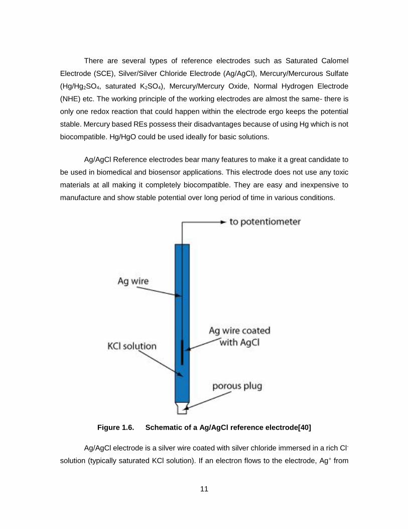
Ag/AgCl Reference electrodes bear many features to make it a great candidate to
be used in biomedical and biosensor applications. This electrode does not use any toxic
materials at all making it completely biocompatible. They are easy and inexpensive to
manufacture and show stable potential over long period of time in various conditions.
Figure 1.6. Schematic of a Ag/AgCl reference electrode[40]
Ag/AgCl electrode is a silver wire coated with silver chloride immersed in a rich Cl-
solution (typically saturated KCl solution). If an electron flows to the electrode, Ag+ from
12
AgCl coating is going to be reduced to Ag and Cl- dissolves into the solution. If electron
flows in the reverse direction, Ag coated with AgCl will give up the electron to get oxidized
to Ag+ which later combines with Cl- from the solution to make insoluble AgCl. The overall
reaction could be written as:
AgCl s e Ag s Cl (5)
1.4.3. Stretchable Electrode
Flexible and stretchable electrodes have been gaining immense attention in recent
days due to high demand for fabricating wearable devices and continuous researches in
this field have brought about mesmerizing advancement. Stretchability of electrodes not
only makes it possible for devices to be wrapped around irregularly shaped objects but it
also ensures conformal contact between electrode and subject for biosensor
application[41]. Stretchable electrodes have been attracting a lot of interest in bio-
integrated device applications such as High-resolution neural interface devices[42],
electrical activity mapping device on heart surface[43] [44], epidermal electronic
systems[45] etc.
Fabrication technique, design and material selection for electrodes to be
stretchable is very important. Even very thin ductile metal electrodes cannot sustain tensile
strain more than 1%[46]. Using thin metal film well attached to pliable substrate shows
much better stretchability due to delocalization of strain over whole surface[47]. Two
design criteria chip in phenomenal characteristics toward stretchable electrode
fabrications: thickness and electrode pattern or configuration[48]. Bending stress tends to
decrease linearly with thickness. That’s why a silicon wafer is brittle whereas nanoscale-
sized ribbons, wires of silicon shows high flexibility. Patterning electrodes into wavy
shapes not only makes them bendable but also stretchable.
Thin film of vapor-deposited gold electrodes onto PDMS substrate have been
demonstrated to have favorable micro and nanostructures which impart excellent
stretechability to the electrode[46]. Direct ink writing provides a great aspect for meeting
the demand for complex and micro-sized design. Direct printed wavy-shaped metallic

13
microelectrodes with concentrated silver nanoparticle inks can withstand repeated
bending and stretching without significant degradation in their electrical properties[49].
Highly conductive and transparent electrode using graphene film has recently been shown
to withstand reversible large strain[50]. Trend of following wavy structure could also be
noticed in electrodes fabricated with Single-walled Carbon Nanotubes (SWNT)[51].
Conventional nano-patterning techniques such as metal evaporation and lift-off
processes often require high temperature, vacuum, chemical etching to which elastic
substrates are susceptible[52]. Several pattering techniques have been developed to
overcome the disadvantages of conventional methods such as micro-contact printing to
design metal patterns on plastic substrates[53], vacuum-evaporated gold deposition for
stretchable electrode[46]. Solution-based metallic nano ink has been a great addition to
the recent technologies to fabricate stretchable electrodes owing to its inherent easiness
and cost-effective approach[54] [55] [56]. In this process nanoparticles or nanowires of
metals are dissolved in a suitable solvent and this solution could be well dispersed on a
pattern by dropcasting or spraying. The patterned electrodes are later heat-treated
(annealed) to fuse the ink materials to achieve a highly conductive pathway. One of the
greatest advantages metallic nano ink offers is that the melting temperature of metal
nanaoparticles decreases with their size to make annealing possible at a lower
temperature without ruining the stretchable substrate[57].
Silver nanowires (AgNWs) and nanoparticles (AgNPs) have been extensively
studied for fabricating stretchable electrodes lately. Silver (Ag) is known to be the best
conductive metal and it is also cheaper compared to noble metals such as gold or
platinum[52]. It is chemically more stable in air than copper and aluminum, syntheses of
AgNWs and AgNPs have been well-established. Silver nanomaterials have been
demonstrated to design and fabricate highly conductive electrode for stretchable
electronics[58].

14
Figure 1.7. Melting temperature of gold nanoparticles with different size[57]
Reprinted (adapted) with permission from (S. H. Ko, I. Park, H. Pan, C. P. Grigoropoulos, A. P. Pisano, C. K. Luscombe, and J. M. J. Fréchet, “Direct nanoimprinting of metal nanoparticles for nanoscale electronics fabrication,” Nano Lett., vol. 7, no. 7, pp. 1869–1877, 2007). Copyright (2007) American Chemical Society.
Silver nanoparticles have much lower melting temperature (~1600 C) than their
bulk counterpart. Thus they can be fused together at low temperature to create a
conductive path for stretchable electrodes. Films created by AgNPs are much denser than
AgNW-films[52]. Patterning techniques for silver nanomaterial-based stretchable
electrodes include direct stamping[59] [57], spray coating[60] [61] [55], ink-jet printing[56]
etc. Direct stamping method is very simple where a stamp’s trenches are filled with silver
nano ink and transferred onto a substrate. The stamp is usually made of hydrophobic
flexible materials such as Polydimethylsiloxane (PDMS) so that there’s minimal sticking of
the ink during transfer. Spraying is advantageous for large area deposition and it also
provides more homogeneity of nano ink deposition. Faster evaporation of the solvent in

15
spraying comes in handy to reduce the chance of coffee ring effect. Spraying could be
done with or without a stencil mask followed by transferring pattern as in direct stamping.
Figure 1.8. Schematic representations for different fabrication techniques using silver nano-ink[52]
(A) Direct stamping followed by annealing (B) Spraying using a stencil mask © [2014] IEEE
1.4.4. Conductive Nano-materials for Lactate Sensors
Some of the sterling attributes of nanomaterials such as high surface area,
excellent electrical conductivity, chemical and electrochemical stability, prospect in highly
stretchable and flexible electrodes have been constantly proving their candidacy to be
used in biosensor applications. Graphene and its derivatives (GO, rGO, multi-layered

16
graphene etc.) have been utilized for biosensor fabrication with various enzymes and
proteins to detect glucose, H2O2, O2, phenolic pollutants, organophosphates, catechol,
ethanol, NADH and nitric oxide[62]. AgNW has been proved to increase electrocatalytic
activities of enzyme and creates an auspicious environment for direct electron transfer
between enzyme and electrode[63]. Nanomaterials have been extensively studied for
electrodes in lactate sensors in recent years. Nanomaterials such as ZnO, carbon
nanotubes (CNT), gold nanoparticles (AuNPs) have proved their excellent catalytic
activity, reliability in enzyme immobilization and electron transfer capability between
electrode and enzyme redox center.
A real-time noninvasive flexible tattoo type perspiration lactate sensor has been
demonstrated[37]. This biosensor was fabricated using carbon fiber and carbon nanotube
(CNT) and shows good linearity in the range 0~20 mM. This amperometric sensor also
proves high reliability under bending loads. A microfluidic chip-based online
electrochemical system (OECS) was developed for in vivo continuous and simultaneous
monitoring of glucose, lactate, and ascorbate in rat brain[64]. Single-walled carbon
nanotubes (SWNTs) used for this sensor fabrication facilitated the electrochemical
oxidation of ascorbate and dehydrogenase for biosensing glucose and lactate. Synergic
action of multi-walled carbon nanotube (MWCNT) and ZnO nanoparticles has been
employed to prepare a lactate sensor with high sensitivity and selectivity[65]. Used ZnO
nanoparticles also provided a favorable environment for immobilized enzyme which
enhances the thermal stability of the sensor. A ZnO nanorod-based biosensor has been
developed recently for potentiometric response of L-lactate[66]. Gold coated glass
substrate was used for growth of ZnO nanorods and enzyme was immobilized on the
nanorods with the help of glutaraldehyde as crosslinker. This biosensor showed fast
response, good selectivity and stability. SWNT–mineral-oil paste has been demonstrated
for rapid detection of lactate at a low potential[67]. SWNT offers accelerated electron
transfer form hydrogen peroxide reaction. A simple, robust platform for lactate sensing
has been proposed using nitrogen-doped carbon nanotubes (N-CNTs)[68]. The
conventional way for amperometric lactate detection is to measure the concentration of
H2O2 by its oxidation. In this N-CNT based sensor, instead of H2O2, the change in the
oxygen reduction current was measured. The sensor shows a sensitivity of 0.04AM-1cm-2
and exhibited a detection limit of 4.1 μM.

17
Highly sensitive nanostructured electrochemical lactate biosensor based on
dehydrogenase enzyme and Au nanoparticles have been reported[69]. The excellent
catalytic ability of Au nanoparticles obviated any additional redox mediator to oxidize
NADH at a less potential. This biosensor exhibits fast response time, high operational and
storage stability and high sensitivity (0.056 ± 0.001 nA/nM) toward NADH with an
amperometric detection limit of 5 nM. The high sensitivity and low detection limit were
explained by the high catalytic activity of AuNPs and the enhanced mass transport to the
electrode surface due to the conglomerated nature of the nanoparticle-based transducer.
Researchers have utilized titanium nanotubes (TNTs) for successful enzyme
immobilization to fabricate lactate sensors. A proposed work shows immobilization of
lactate oxidase on the three-dimensional porous TNT network to make an electrochemical
biosensor for lactate detection[70]. The nanotubes offer the pathway for direct electron
transfer between the electrode surface and the active redox centers of lactate oxidase,
which enables the biosensor to work at a low working potential and avoids the influence
of the presence of O2 on the amperometric current response.

18
Chapter 2. Fabrication of Silver Nanoparticle-based Electrode
2.1. Introduction
For the lactate sensor, A AgNP-based simple stamping technique was adopted to
fabricate the electrodes. AgNPs are well known for their excellent electrochemical
properties and catalytic activity. Electrochemical sensors incorporating AgNPs have been
demonstrated to be able to provide higher response with shorter response time and lower
detection limit. AgNPs electrodeposited gold interdigital electrodes have been reported to
show excellent promises of higher sensitivity towards hydrogen peroxide[71]. A glucose
biosensor was demonstrated to use AgNPs to modify platinum electrode, which shows
significant increase in current response[72]. Hydrogen peroxide sensor using glassy
carbon electrodes (GCE) modified with electrodeposited AgNPs shows enhanced
sensitivity and stability[73]. Moreover, AgNPs have proved their potential to increase
activity of immobilized enzyme as well[74]. Electrodes were fabricated in cross-serpentine
pattern for high conformability, low impedance and greater flexibility of the sensor.
2.2. Electrode Fabrication
2.2.1. Synthesis of Silver Nanoparticles
Silver nanoparticles were synthesized as described elsewhere[59] with a tad of
modification. Nanoparticles were synthesized using phenylhydrazine to reduce silver
acetate. Toluene and Hexadecylamine were used as solvent and capping agent
respectively. A round bottom flask was used for the synthesis process and the solution
was kept in incessant stirring. Prepared nanoparticle solution was washed with
isopropanol (IPA) and methanol. Solution in the flask turns purple adumbrating the
synthesized silver nanoparticles. Washed solution was filtered and dried in a vacuum oven
overnight. Synthesized dried nanoparticles were then scratched off the filter paper and
ready to be used.

19
2.2.2. Pattern Transfer
All three electrodes were fabricated using simple spray coating technique followed
by direct stamping. A negative photoresist, SU-8 was used to fabricate silicon master
pattern by conventional photolithography. Patterns were replicated as trenches onto
flexible PDMS stamps. 3 wt% AgNP solution was prepared using toluene as solvent and
sprayed on PDMS stamps using IWATA HP-CR air brush in fume hood at 15 psi. Adhesive
tape was then used to remove nanoparticles from unwanted areas (i.e protrusive regions)
of the stamps leaving AgNPs only in the cross-serpentine-shaped furrows. After allowing
a fleeting drying period, a thin layer of UV-curable PU prepolymer (urethane acrylate 90
wt% and photo-initiator 5 wt% in PGMEA) was homogeneously smeared on the top the
stamps. A PET sheet was brought in contact with PU covered surface of stamp and
moderate pressure was applied to get rid of any air bubble in the PU. Next step is to cure
PU and to do so the entire assembly comprised of stamp, PU and PET was exposed to
UV light for 7 mins. After curing, PET was peeled off the stamps and thus AgNP-based
cross-serpentine electrodes get transferred with crosslinked PU. Later they were annealed
at 1600C for 1.5 hours and slowly cooled down. Surface area of the fabricated working
electrode was measured as 32 mm2. Electrical connections were made using silver
conductive epoxy and 0.19 mm enameled copper wires. Adheoro 5 minute epoxy was
used to secure and insulate the connections.
20
2.3. Characterization of Fabricated Electrodes
2.3.1. Cross-serpentine Pattern
All three electrodes (working, counter and reference) were fabricated in cross-
serpentine pattern. The reason behind it is to achieve high flexibility while maintaining
conformal contact of the sensor when it comes to attaching to human epidermis for
continuous measurement. Each arc of the serpentine pattern has dimensions of 300 μm
in inner radius, 350 μm in outer radius, 50 μm in width and 20 μm in thickness.
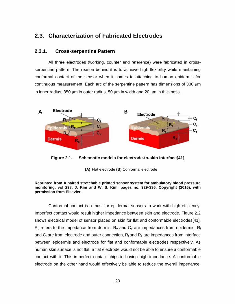
Figure 2.1. Schematic models for electrode-to-skin interface[41]
(A) Flat electrode (B) Conformal electrode
Reprinted from A paired stretchable printed sensor system for ambulatory blood pressure monitoring, vol 238, J. Kim and W. S. Kim, pages no. 329-336, Copyright (2016), with permission from Elsevier.
Conformal contact is a must for epidermal sensors to work with high efficiency.
Imperfect contact would result higher impedance between skin and electrode. Figure 2.2
shows electrical model of sensor placed on skin for flat and conformable electrodes[41].
Rd refers to the impedance from dermis, Re and Ce are impedances from epidermis, Ri
and Ci are from electrode and outer connection, Rf and Rc are impedances from interface
between epidermis and electrode for flat and conformable electrodes respectively. As
human skin surface is not flat, a flat electrode would not be able to ensure a conformable
contact with it. This imperfect contact chips in having high impedance. A conformable
electrode on the other hand would effectively be able to reduce the overall impedance.
21
Cross-serpentine shape for electrode have been demonstrated to provide a basis for
conformable contact, even in roughest areas of skin[75]. Electrodes with this design also
have been demonstrate excellent robustness against repeated cycles of
pinching/releasing of the skin.
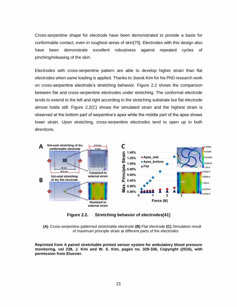
Electrodes with cross-serpentine pattern are able to develop higher strain than flat
electrodes when same loading is applied. Thanks to Jiseok Kim for his PhD research work
on cross-serpentine electrode’s stretching behavior. Figure 2.2 shows the comparison
between flat and cross-serpentine electrodes under stretching. The conformal electrode
tends to extend to the left and right according to the stretching substrate but flat electrode
almost holds still. Figure 2.2(C) shows the simulated strain and the highest strain is
observed at the bottom part of serpentine’s apex while the middle part of the apex shows
lower strain. Upon stretching, cross-serpentine electrodes tend to open up in both
directions.
Figure 2.2. Stretching behavior of electrodes[41]
(A) Cross-serpentine patterned stretchable electrode (B) Flat electrode (C) Simulation result of maximum principle strain at different parts of the electrodes
Reprinted from A paired stretchable printed sensor system for ambulatory blood pressure monitoring, vol 238, J. Kim and W. S. Kim, pages no. 329-336, Copyright (2016), with permission from Elsevier.
22
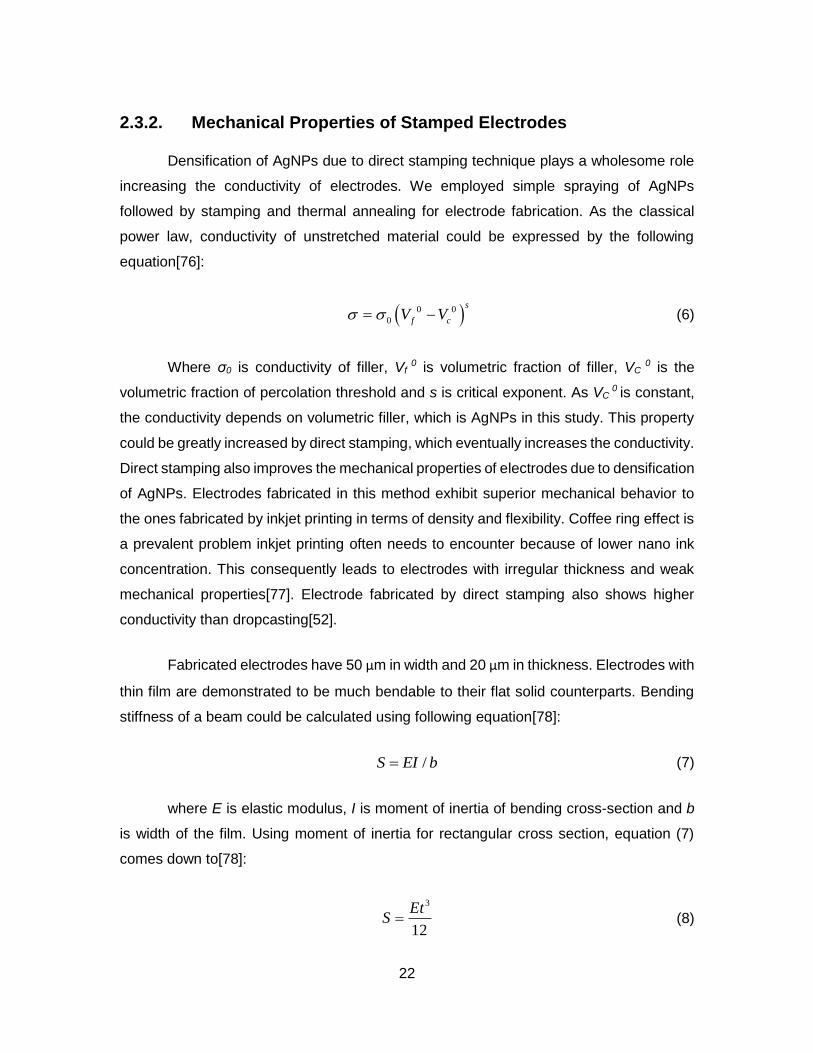
2.3.2. Mechanical Properties of Stamped Electrodes
Densification of AgNPs due to direct stamping technique plays a wholesome role
increasing the conductivity of electrodes. We employed simple spraying of AgNPs
followed by stamping and thermal annealing for electrode fabrication. As the classical
power law, conductivity of unstretched material could be expressed by the following
equation[76]:
0 0
0
s
f cV V (6)
Where σ0 is conductivity of filler, Vf 0 is volumetric fraction of filler, VC
0 is the
volumetric fraction of percolation threshold and s is critical exponent. As VC 0 is constant,
the conductivity depends on volumetric filler, which is AgNPs in this study. This property
could be greatly increased by direct stamping, which eventually increases the conductivity.
Direct stamping also improves the mechanical properties of electrodes due to densification
of AgNPs. Electrodes fabricated in this method exhibit superior mechanical behavior to
the ones fabricated by inkjet printing in terms of density and flexibility. Coffee ring effect is
a prevalent problem inkjet printing often needs to encounter because of lower nano ink
concentration. This consequently leads to electrodes with irregular thickness and weak
mechanical properties[77]. Electrode fabricated by direct stamping also shows higher
conductivity than dropcasting[52].
Fabricated electrodes have 50 μm in width and 20 μm in thickness. Electrodes with
thin film are demonstrated to be much bendable to their flat solid counterparts. Bending
stiffness of a beam could be calculated using following equation[78]:
/S EI b (7)
where E is elastic modulus, I is moment of inertia of bending cross-section and b
is width of the film. Using moment of inertia for rectangular cross section, equation (7)
comes down to[78]:
3
12
EtS (8)
23
where t is the thickness of the film. Therefore the stiffness is directly proportional
to the third power of film thickness. Hence bending stiffness becomes significantly low for
very thin films which leads to better bendability.
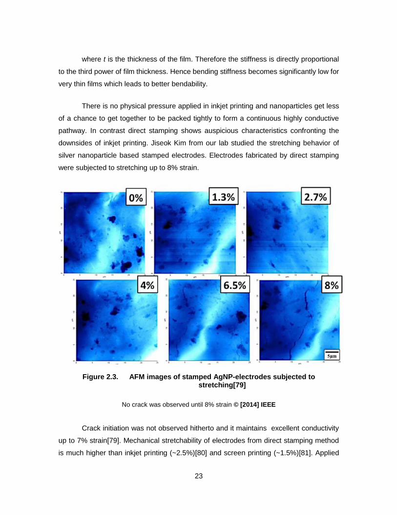
There is no physical pressure applied in inkjet printing and nanoparticles get less
of a chance to get together to be packed tightly to form a continuous highly conductive
pathway. In contrast direct stamping shows auspicious characteristics confronting the
downsides of inkjet printing. Jiseok Kim from our lab studied the stretching behavior of
silver nanoparticle based stamped electrodes. Electrodes fabricated by direct stamping
were subjected to stretching up to 8% strain.
Figure 2.3. AFM images of stamped AgNP-electrodes subjected to stretching[79]
No crack was observed until 8% strain © [2014] IEEE
Crack initiation was not observed hitherto and it maintains excellent conductivity
up to 7% strain[79]. Mechanical stretchability of electrodes from direct stamping method
is much higher than inkjet printing (~2.5%)[80] and screen printing (~1.5%)[81]. Applied

24
pressure from stamping makes AgNPs come closer to each other to be packed densely
and hence there is less presence of pores in the structure which essentially means less
availability of sites for crack initiation.
25
Chapter 3. Modification of Electrodes for Sweat Lactate Sensor
3.1. Working Electrode Modification
3.1.1. Anionic Polymer
Not only the target analyte but also interferences present in the fluid react on the
electrode surface in an electrochemical biosensor. Different anionic substances such as
ascorbate, urate could potentially interfere and adulterate the response from lactate.
Generally, high potential is required for oxidation or reduction of H2O2 for many electrode
materials. Such high potential is very conducive to oxidize different reducing species
present in target analyte[82]. Extensive efforts have been developed to minimize or
eliminate the effect from these interferences in biosensors[83] [84] [85].
Incorporating an active component such as enzyme, redox reagent or ligand in the
outer layer of sensor would exterminate in-coming interferants before they reach the
electrode surface[86]. Although this approach has experienced some in vitro applications,
no in vivo application has incorporated it yet[87]. Second approach is to lower the required
potential to make the redox reaction happen. Interferants often tend to oxidize or reduce
at a higher potential. Incorporating a mediator for easy electron shuttle between enzyme
and electrode would bring down the required potential. Although this approach limits the
electroactivity of interferants due to low potential, it does not confirm for them to be
electrocatalytically oxidized. Also this approach could give way its long term stability and
reliable mediators are still under research[87]. The third approach is incorporating a
passive membrane in the biosensor that possesses pores for easy passage of the target
molecule while retarding or repelling interferences due to ionic or chemical selectivity.
An anionic polymer with net negative charge could be used to block other
negatively charged molecules such as ascorbate while pores in the polymer would let
through uncharged molecules such as hydrogen peroxide in the sensor. As lactate is also

26
an anion, it is essential to have the anionic polymer after the enzyme layer where lactate
would be broken down to pyruvate and hydrogen peroxide.
3.1.2. Nafion as Anionic Polymer
Perfluorosulfonic membrane Nafion was first developed by Dupont de Nemours in
1962. Sulfonated fluoropolymer has a hydrophobic backbone of polytetrafluoroethylene
(PTFE) with side chains containing hydrophilic sulfonate ionic group[88] [89]. The
chemical formula is:
Due to unique ionic selectivity, chemical resistance, excellent thermal and
mechanical stability; Nafion has received substantial attention as electrolyte polymer in
chlor-alkali electrolyzers replacing sodium amalgam or diaphragm cells and in proton
exchange membrane (PEM) fuel cells[88] [90]. The hydrophilic sulfonic acid group –SO3H
has affinity for and dissociates in the presence of water. As the water content is increased,
the proton (H+) become less strongly bound to the structure and facilitates proton
conductivity. As the acid group dissociates, the proton bonds with water molecule creating
hydromium ion (H3O+) leaving Nafion as negatively charged[91]. As the membrane sops
up more and more water, it swells to accommodate the solvent. However the PTFE
backbone of Nafion is hydrophobic hence it can be seen to be antipathetic to increasing
water. This diametrical phenomenon eventually leads to an equilibrium of water content.
Relative selectivity of Nafion membrane blocks anions while permitting other
molecules and cations pass through even under high current densities and ion
concentration gradients. Nafion’s application as selective membrane to exclude interfering
substances has been well known and reported[8]. Nafion is an artificial polymer well-
known for its excellent biocompatibility and permselectivity[92] [90] [93]. A novel NO
electrochemical sensor has been reported using single walled carbon nanotube (SWCNT)

27
and Nafion to modify the surface of carbon fiber microdisk electrode[94]. The Nafion
membrane provided a good barrier to some anionic interferences such as nitric acid and
ascorbic acid without losing response to nitric oxide. Another NO sensor consisted of a
single etched carbon fiber working electrode and Ag/AgCl reference electrode was
reported where the sensor tip was dipped into a Nafion solution three times each for 20 s
and dried at 90°C for 20 min to form a perm-selective coating membrane[95]. The
negatively charged Nafion shows its ability to eliminate anionic interferences such as
ascorbic acid and nitrite. However, significant decrease of sensitivity has been observed
both for sensors incorporating Nafion as mixed with enzyme matrix[96] and used as
separate layer on the sensor surface[97]. Thus an optimum concentration of the selective
membrane needs to come of age. Diluted Nafion solution with a concentration of 5% has
been showed recently to permit maximum hydrogen peroxide to pervade through while
still effectively acting as impermeable membrane to block ascorbate[8].
Figure 3.1. AFM image of dropcasted and air-dried Nafion layer
Nafion was received as a 20 wt. % mixture of lower aliphatic alcohols and water.
It was dissolved in ethanol to prepare diluted (5% v/v) Nafion solution. To prepare the
28
Nafion selective membrane, 20 μL of the solution was dropcasted on the electrode surface
and left it to dry for an hour. The Atomic Force Microscopy (AFM) reveals the surface
morphology of the dropcasted Nafion layer (Figure 3.1). The average pore size of this
layer was found to be around 4.0 μm.
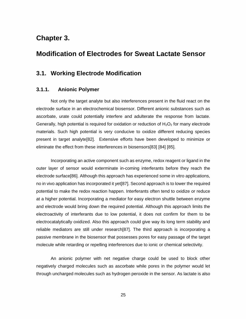
3.1.3. Cellulose Acetate as Anionic Polymer
As effective it is to make the sensor’s response interference free, Nafion also
seems to give hydrogen peroxide a hard time to pass through and as a result the response
tends to let up. Cellulose acetate membrane has been reported to be a biocompatible and
permeable membrane for hydrogen peroxide[98] and demonstrated to be dexterous in
eliminating effect from interferences[99] [18] [100] [87] [101]. A sensor was prepared using
5% cellulose acetate instead of Nafion to compare its performance in sensitivity and also
selectivity. AFM image shows (Figure 3.2) the morphology and bigger pores in the
dropcasted cellulose acetate membrane.
Figure 3.2. AFM image of dropcasted and air-dried cellulose acetate layer
29
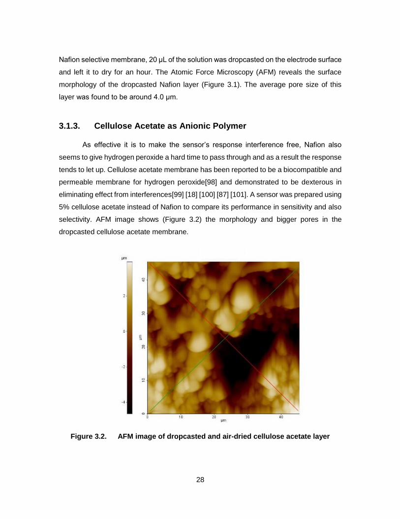
The average pore size (~12 μm) found for this membrane is much bigger that
noticed for Nafion membrane. Figure 3.3 demonstrates the sensors performance as
lactate solutions of different concentrations were added. The sensitivity was recorded as
290.7 nA/mM which is tad higher than the one prepared with Nafion. Also the response
seems to lose linearity after 15 mM; the coefficient of determination is 0.9604. Figure 3.4
shows the sensor’s response to interference and the sensitivity towards ascorbate was
6.82 nA/μM.
Figure 3.3. Sensor response to lactate with cellulose acetate membrane
Higher response of this sensor to both lactate and ascorbate could be attributed to
the bigger pores present in cellulose acetate membrane. Although sensor prepared with
cellulose acetate shows higher sensitivity towards lactate, sensitivity towards ascorbic
acid is also higher. Response found for 10 μM ascorbic acid in 10 mM of lactate was
2.74% of the response from lactate while it is only 0.74% for the sensor prepared with
Nafion. Hence Sensor prepared using Nafion was eventually used to conduct all the in-
vitro experiments. Table 3.1 compares the performance of the two sensors fabricated
using Nafion and cellulose acetate.

30
Figure 3.4. Sensor response to interference with cellulose acetate membrane
Table 3.1. Performance with different interference rejection membranes
Nafion Cellulose Acetate
Lactate Sensitivity 81.7 nA/mM 290.7 nA/mM
R2 0.9732 0.9604
Ascorbic acid sensitivity 3.12 nA/μM 6.82 nA/μM

31
3.1.4. Enzyme Immobilization
Before getting into how we immobilized Lactate oxidase let’s shed some light on
importance of enzyme immobilization and different immobilization techniques. Enzymes
are proteins to accelerate or facilitate chemical reaction. As a simple example consider
fermentation process where enzymes are frequently used. Many a time enzymes and
substrates are amalgamated together to form the product. The product is then extracted
and the rest of mixture including the enzyme is discarded. Being expensive to produce,
discarding enzyme in such manner is quite prodigal. The cost-effective approach would
be to keep them for future use as enzymes are not consumed during reactions.
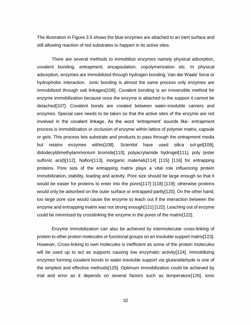
Figure 3.5. Illustration of immobilized enzyme[102]
One common way to do so is to immobilize enzymes so that they could be retained
instead of getting washed away or discarded during or after the process. Also, enzyme’s
structure could be destroyed at the air-water interface and as a result they could easily
lose their catalytic activity[103]. Enzymes which are physically confined in defined region
contain their catalytic activity possess the ability to be repeatedly and continuously used.
By attachment to an inert support material, bioactive molecules such as enzymes may be
rendered, retaining catalytic activity and therefore extending their effective life[104] [105].
32
The illustration in Figure 3.5 shows the blue enzymes are attached to an inert surface and
still allowing reaction of red substrates to happen in its active sites.
There are several methods to immobilize enzymes namely physical adsorption,
covalent bonding, entrapment, encapsulation, copolymerization etc. In physical
adsorption, enzymes are immobilized through hydrogen bonding, Van der Waals’ force or
hydrophobic interaction. Ionic bonding is almost the same process only enzymes are
immobilized through salt linkages[106]. Covalent bonding is an irreversible method for
enzyme immobilization because once the enzyme is attached to the support it cannot be
detached[107]. Covalent bonds are created between water-insoluble carriers and
enzymes. Special care needs to be taken so that the active sites of the enzyme are not
involved in the covalent linkage. As the word ‘entrapment’ sounds like- entrapment
process is immobilization or occlusion of enzyme within lattice of polymer matrix, capsule
or gels. This process lets substrate and products to pass through the entrapment media
but retains enzymes within[108]. Scientist have used silica sol-gel[109],
didodecyldimethylammonium bromide[110], polyacrylamide hydrogel[111], poly (ester
sulfonic acid)[112], Nafion[113], inorganic materials[114] [115] [116] for entrapping
proteins. Pore size of the entrapping matrix plays a vital role influencing protein
immobilization, stability, loading and activity. Pore size should be large enough so that it
would be easier for proteins to enter into the pores[117] [118] [119]; otherwise proteins
would only be adsorbed on the outer surface or entrapped partly[120]. On the other hand,
too large pore size would cause the enzyme to leach out if the interaction between the
enzyme and entrapping matrix was not strong enough[121] [122]. Leaching out of enzyme
could be minimized by crosslinking the enzyme in the pores of the matrix[122].
Enzyme immobilization can also be achieved by intermolecular cross-linking of
protein to other protein molecules or functional groups on an insoluble support matrix[123].
However, Cross-linking to own molecules is inefficient as some of the protein molecules
will be used up to act as supports causing low enzymatic activity[124]. Immobilizing
enzymes forming covalent bonds to water-insoluble support via glutaraldehyde is one of
the simplest and effective methods[125]. Optimum immobilization could be achieved by
trial and error as it depends on several factors such as temperature[126], ionic
33
strength[127] and pH[128] of the solution, concentration of enzyme[129] and reaction
time[130].
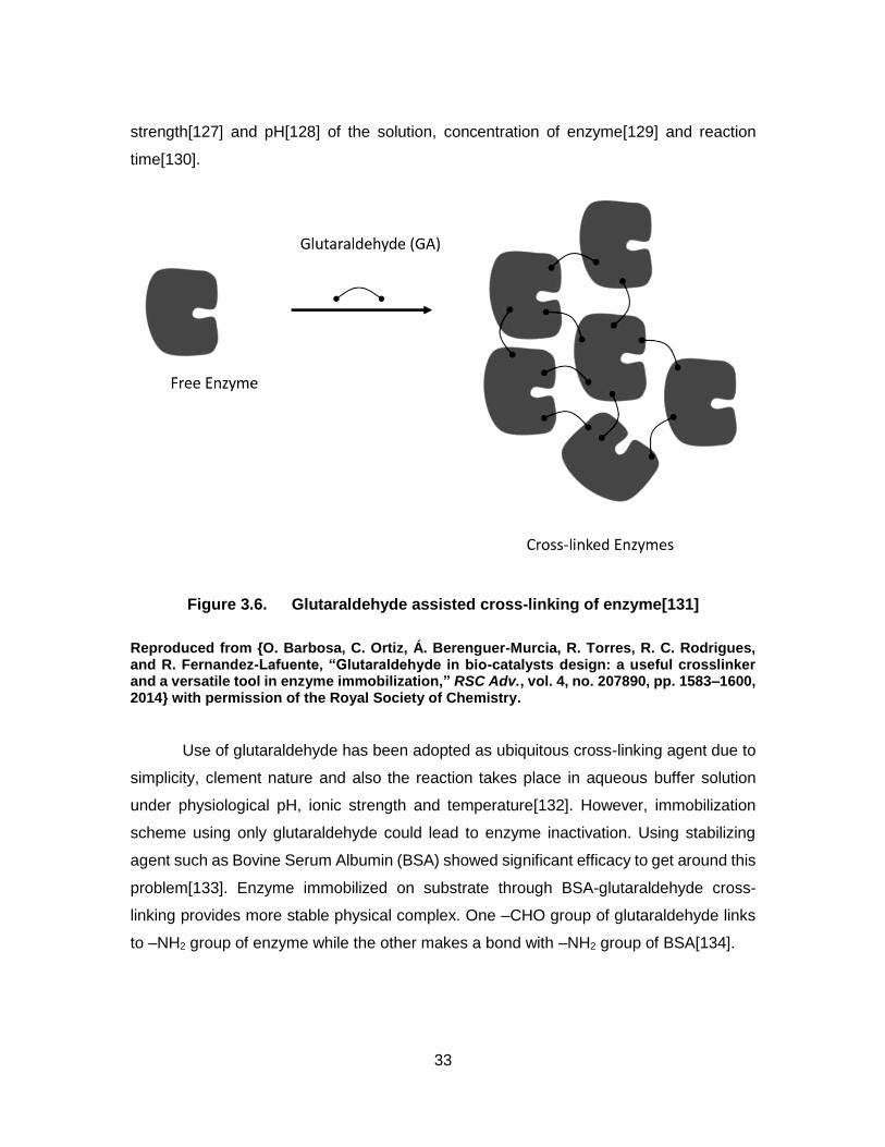
Figure 3.6. Glutaraldehyde assisted cross-linking of enzyme[131]
Reproduced from {O. Barbosa, C. Ortiz, Á. Berenguer-Murcia, R. Torres, R. C. Rodrigues, and R. Fernandez-Lafuente, “Glutaraldehyde in bio-catalysts design: a useful crosslinker and a versatile tool in enzyme immobilization,” RSC Adv., vol. 4, no. 207890, pp. 1583–1600, 2014} with permission of the Royal Society of Chemistry.
Use of glutaraldehyde has been adopted as ubiquitous cross-linking agent due to
simplicity, clement nature and also the reaction takes place in aqueous buffer solution
under physiological pH, ionic strength and temperature[132]. However, immobilization
scheme using only glutaraldehyde could lead to enzyme inactivation. Using stabilizing
agent such as Bovine Serum Albumin (BSA) showed significant efficacy to get around this
problem[133]. Enzyme immobilized on substrate through BSA-glutaraldehyde cross-
linking provides more stable physical complex. One –CHO group of glutaraldehyde links
to –NH2 group of enzyme while the other makes a bond with –NH2 group of BSA[134].

34
Figure 3.7. Enzyme immobilization using BSA and GA
(A) Glutaraldehyde reaction with amine residues of AL (Alginate lyase). (B) Glutaraldehyde reaction with amine residues of BSA incubated with AL preserving AL active site[133]
Reproduced from { G. A. Islan, Y. N. Martinez, A. Illanes, and G. R. Castro, “Development of novel alginate lyase cross-linked aggregates for the oral treatment of cystic fibrosis,” RSC Adv., vol. 4, no. 23, pp. 11758–11765, 2014.}, with permission of the Royal Society of Chemistry.
Glutaraldehyde (GA) - as a cross-linking agent; was used to immobilize Lactate
Oxidase (LOD) in conjunction with Bovine Serum Albumin (BSA) as stabilizing reagent.
50 U of LOD was dissolved in 500 μL of Phosphate Buffer Saline (PBS) and was equally
separated into 25 aliquots; each containing 2 U of LOD. All aliquots were stored at -200C.

35
A total mass of 6 mg of BSA was dissolved in 40 μL of PBS and stored at 40C. Prepared
BSA solution was mixed with 20 μL of LOD solution and stored at 40C. Glutaraldehyde
(GA) was diluted into 10% solution with DI water and a 30 μL of diluted GA solution was
concocted with LOD/BSA mixture and 20 μL of LOD/BSA/GA of the solution was drop
casted on Nafion coated electrode surface. After waiting for 2 hours, the prepared sensor
was gently rinsed with PBS to get rid of excess GA.
3.2. Reference Electrode Modification and Optimization
3.2.1. Chloridization
One of the most common reference electrode used for electrochemical
measurements is silver/silver chloride (Ag/AgCl) electrode. These are quite stable, robust,
usable under wide variety of conditions and cheap to fabricate. Most common technique
to chloridize silver is to electroplate it in a chloride containing solution. Electroplating of a
silver wire could be achieved by placing it in a cell containing 0.1~1 M HCl or KCl and
applying about 0.5 mA/cm2 for 30 minutes. If chloridized in the absence of light, the color
should turn in to reddish dark brown or pale tan otherwise[135]. Periodic reversal of the
polarity of the electrode while plating tends to yield a more stable reference electrode.
After washing with water, the color of the coating ranges from pink to shade of plum.
An easy and inexpensive alternative method could be employed is to soak silver
in hypochlorite solution that obviates the need for an electrochemical cell[136] [137].
Commercial household bleach can be used in this regard. Ag/AgCl reference electrodes
for the lactate sensor were prepared by dunking AgNP-electrodes in 8.25% Clorox bleach
for 1, 5 and 10 mins and then they were washed with DI water.
The reference electrode used in the sensor could be defined as a pseudo-
reference or quasi-reference electrode. The difference between a true reference electrode
and a pseudo-reference electrode is the lack of thermodynamic equilibrium in latter case
due to the absence of a chloride containing solution around the AgCl coated Ag[138] [139].
Pseudo reference electrodes need to be calibrated by using a reference redox system or
conventional reference electrode. Pseudo-reference electrodes usually work over a
36
limited range of conditions such as pH and temperature. The advantage of using a
pseudo-reference electrode is their simplicity. As there is no chloride solution needed to
keep the Ag/AgCl immersed in, it not only makes biosensors much simpler and portable
but also reduces the chance of the test solution to be contaminated by the solvent
molecules or ions that conventional reference electrode may transfer. Although under
suitably selected conditions the potential of the pseudo-reference electrode is unknown, it
can be surprisingly constant during the experiments[140].
3.2.2. Characterization of Ag/AgCl Electrode
Electrodes fabricated from metal nanoparticles exhibit larger surface-to-volume
ratio compared to the ones fabricated with their bulk metal counterpart which means
presence of more potential sites for reaction to take place. Scattering and absorbing light
in visible range is one of the unique characteristics of noble metal nanoparticles[141].
Distinctive color of nanoparticles depends on their morphology and size unlike dyes and
pigments. At specific frequency, when the conductive electrons of nanoparticles are
excited by an external light, they undergo a collective oscillation which is known as surface
plasmon resonance[142]. Due to this oscillatory phenomenon, nanoparticles show strong
absorption and scattering behavior. Optical and physical properties of noble metal
nanoparticles are significantly different from their bulk metal counterparts[143] [144]. Silver
nanoparticles show momentous efficacy towards absorbing and scattering light in visible
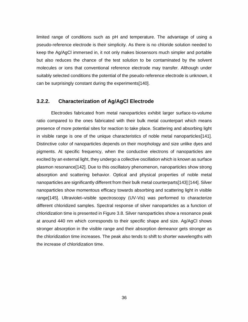
range[145]. Ultraviolet–visible spectroscopy (UV-Vis) was performed to characterize
different chloridized samples. Spectral response of silver nanoparticles as a function of
chloridization time is presented in Figure 3.8. Silver nanoparticles show a resonance peak
at around 440 nm which corresponds to their specific shape and size. Ag/AgCl shows
stronger absorption in the visible range and their absorption demeanor gets stronger as
the chloridization time increases. The peak also tends to shift to shorter wavelengths with
the increase of chloridization time.

37
Figure 3.8. UV-Vis spectra of AgNPs and Chloridized AgNPs
Resonance peak for unchloridized AgNP was found at 440 nm. Peak tends to move to shorter wavelength for chloridized samples
To determine different phases present in microstructure of different electrodes and
size of AgNPs, Scanning Electron Microscopy (SEM) was used coupled with Energy
Dispersive X-ray Spectroscopy (EDS). Average diameter of synthesized AgNPs is around
50 nm. Upon chloridization, AgCl particles start to form on AgNP surfaces and as the
chloridization time was increased, AgCl tends to enshroud AgNPs forming much smoother
surface morphology. Table 3.2 provides the percentage amount of silver and chlorine in
different chloridized samples achieved from Energy-dispersive X-ray spectroscopy (EDS).
Figure 3.10 shows the surface roughness of cured AgNPs transferred onto the flexible
substrate. Root mean square (rms) value for surface roughness of AgNP-electrode is
found to be 313.7 nm which is quite higher than rms roughness of the modified Ag/AgCl
reference electrode (164.018 nm for 5 min long modified electrode). It is noteworthy that
high energy electron beam (> 2 kV) and a slower scan rate tend to ruin the samples by
burning AgCl. EDS spectra of chloridized and unchloridized AgNP-electrodes have been
added under Appendix A.

38
Figure 3.9. lactate sensor with different functional layers
(A) Schematic illustration of different layers of the sensor (B) Fabricated sensor
Figure 3.10. Surface morphology of stamped electrodes
(A) AgNPs for working and counter electrodes (B) Chloridized AgNPs to fabricate Ag/AgCl reference electrode

39
Table 3.2. Chemical Composition of Ag and Cl in different AgNP-electrodes
Chloridization time Ag wt% Cl wt%
0 min 85.99 0
1 min 88.31 3.87
5 min 79.60 8.82
10 min 73.79 10.26
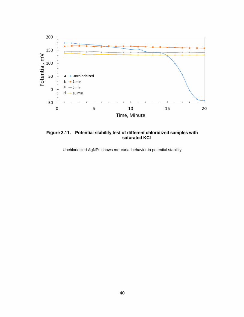
3.2.3. Stability of Reference Electrode
Long-term potential stability is the most desired characteristics of a reference
electrode. Stability performance tests were performed in saturated KCl using a BASi®
standard Ag/AgCl reference electrode as counter electrode. All the electrodes were tested
three times each in a span of 20 mins. Unchloridized electrode with unmodified AgNPs
shows erratic behavior in its potential stability (Figure 3.11). Electrical potential changes
significantly at every minute and after 14 min it plummets down from 140.8 mV to -42.4
mV over just 5 min of duration. Modified Ag/AgCl electrodes show excellent performance
keeping their potential almost constant with insignificant variations. Although the sample
(c) comes out to be topnotch in the first experiment, sample (b) vanquishes others when
it comes to three experiments all together (2nd and 3rd experiment results are plotted under
Appendix B). Standard deviations for samples (a), (b), (c) and (d) are calculated to be
108.05, 7.81, 12.95 and 12.57 after three experiments. Modified AgNP electrode sample
(b) dipped in bleach for 1 min was thus used as reference electrode for the lactate
biosensor.
40
Figure 3.11. Potential stability test of different chloridized samples with saturated KCl
Unchloridized AgNPs shows mercurial behavior in potential stability
41
Chapter 4. Characterization and Analysis of Fabricated Lactate Sensor
4.1. In-vitro Experiment
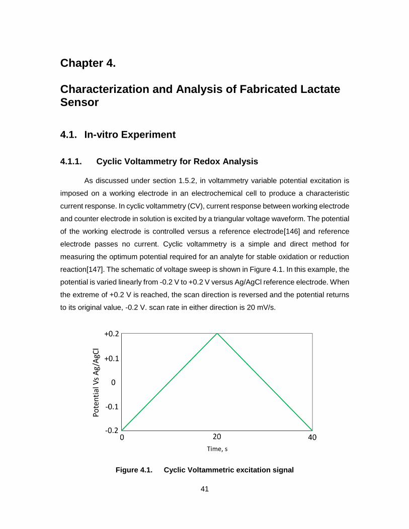
4.1.1. Cyclic Voltammetry for Redox Analysis
As discussed under section 1.5.2, in voltammetry variable potential excitation is
imposed on a working electrode in an electrochemical cell to produce a characteristic
current response. In cyclic voltammetry (CV), current response between working electrode
and counter electrode in solution is excited by a triangular voltage waveform. The potential
of the working electrode is controlled versus a reference electrode[146] and reference
electrode passes no current. Cyclic voltammetry is a simple and direct method for
measuring the optimum potential required for an analyte for stable oxidation or reduction
reaction[147]. The schematic of voltage sweep is shown in Figure 4.1. In this example, the
potential is varied linearly from -0.2 V to +0.2 V versus Ag/AgCl reference electrode. When
the extreme of +0.2 V is reached, the scan direction is reversed and the potential returns
to its original value, -0.2 V. scan rate in either direction is 20 mV/s.
Figure 4.1. Cyclic Voltammetric excitation signal

42
All electrochemical experiments were performed on a CHI 1205B electrochemical
analyzer (CH Instruments Inc.). Three electrodes were connected to the potentiostat via
copper wires and alligator clips. Potential of the working electrode was varied against the
on-sensor reference electrode for CV. The electrical resistant of the control circuit for
reference electrode is so large that it essentially draws no current. Electricity is conducted
between working and counter electrodes through the solution. The independent variable
in the experiment is the potential of the working electrode versus reference electrode and
scan rate.
Figure 4.2. Cyclic Voltammogram of 10 mM lactate vs Ag/AgCl
Figure 4.2 demonstrates the cyclic voltammogram for 200 μL of 10 mM lactate
solution between -1.0 V and +1.0 V at 50 mV/s scan rate. All the lactate solutions were
prepared in phosphate buffer saline (PBS, pH=7.0). Initial tiny cathodic current is observed
in the range -1.0 V to -0.3 V which eventually decreases to zero which arises from the
reduction of water to give H2. No significant current is observed between -0.3 V to 0 V
because there is no oxidizable or reducible species present in this potential range. As the
potential rises, an anodic current begins to come forth because of the oxidation of
hydrogen peroxide. The anodic peak current was found at 0.65 V, which is also the

43
average from five different cyclic voltammograms and was thus used as the operating
potential for all subsequent studies.
At 1.0 V the scan direction is switched but the current continues to be anodic even
the scan goes more to the negative potential because the potential is still positive enough
for the oxidation of H2O2. As the potential sweeps in the negative direction, oxidation of
H2O2 no longer occurs, current goes to zero and then becomes cathodic. The cathodic
current stems from the reduction of H2O2 as the following reaction[148]:
2 2 22 2 2e H H O H O (9)
However a definite cathodic peak was not observed, cathodic current reaches is
maximum value between -0.45 V and -0.7 V.
4.1.2. Amperomtric i-t curve and calibration
Amperometric i-t curve measures the current at a fixed working electrode potential
and the resulting current from the electrode is monitored as a function of time. This current-
time curve represents the change in the concentration gradient. As time goes, the reactant
depletes at the working electrode surface and the slope of the response decreases as
well. Chronoamperometry could be applied to study different processes occurring at
electrode surface[149]. Figure 4.3 shows chronoamperometric response of the lactate
biosensor upon addition of lactate with different concentrations. All In vitro experiments
were carried out by dropcasting and bearing off 200 μL of solution with different
concentrations on the sensor each time. Current response rises as the concentration
increases from 0 mM to 25 mM. Sensor response reaches to 90% of its final steady value
within 60 seconds (response time). The uptick in response observed upon addition of 0
mM of lactate could be attributed as constant background current, I0 and can be
corrected[87].

44
Figure 4.3. Amperometric i-t curve at 0.65 V Vs Ag/AgCl
Figure 4.4. Calibration of sensor responses for different lactate concentrations
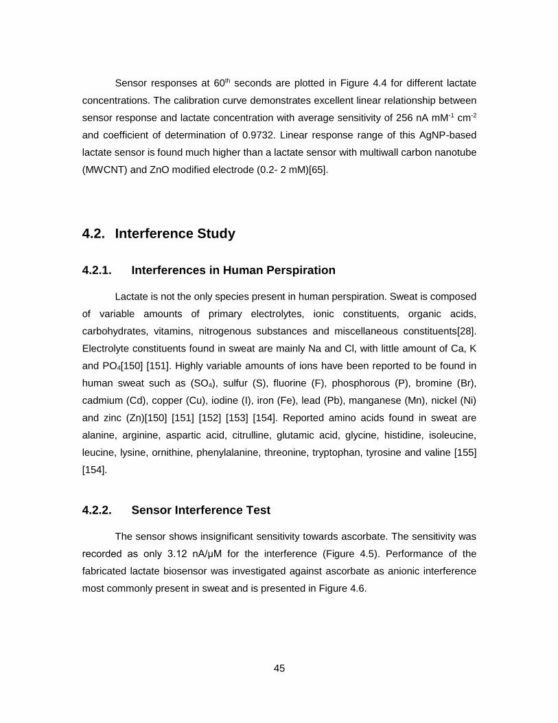
45
Sensor responses at 60th seconds are plotted in Figure 4.4 for different lactate
concentrations. The calibration curve demonstrates excellent linear relationship between
sensor response and lactate concentration with average sensitivity of 256 nA mM-1 cm-2
and coefficient of determination of 0.9732. Linear response range of this AgNP-based
lactate sensor is found much higher than a lactate sensor with multiwall carbon nanotube
(MWCNT) and ZnO modified electrode (0.2- 2 mM)[65].
4.2. Interference Study
4.2.1. Interferences in Human Perspiration
Lactate is not the only species present in human perspiration. Sweat is composed
of variable amounts of primary electrolytes, ionic constituents, organic acids,
carbohydrates, vitamins, nitrogenous substances and miscellaneous constituents[28].
Electrolyte constituents found in sweat are mainly Na and Cl, with little amount of Ca, K
and PO4[150] [151]. Highly variable amounts of ions have been reported to be found in
human sweat such as (SO4), sulfur (S), fluorine (F), phosphorous (P), bromine (Br),
cadmium (Cd), copper (Cu), iodine (I), iron (Fe), lead (Pb), manganese (Mn), nickel (Ni)
and zinc (Zn)[150] [151] [152] [153] [154]. Reported amino acids found in sweat are
alanine, arginine, aspartic acid, citrulline, glutamic acid, glycine, histidine, isoleucine,
leucine, lysine, ornithine, phenylalanine, threonine, tryptophan, tyrosine and valine [155]
[154].
4.2.2. Sensor Interference Test
The sensor shows insignificant sensitivity towards ascorbate. The sensitivity was
recorded as only 3.12 nA/μM for the interference (Figure 4.5). Performance of the
fabricated lactate biosensor was investigated against ascorbate as anionic interference
most commonly present in sweat and is presented in Figure 4.6.
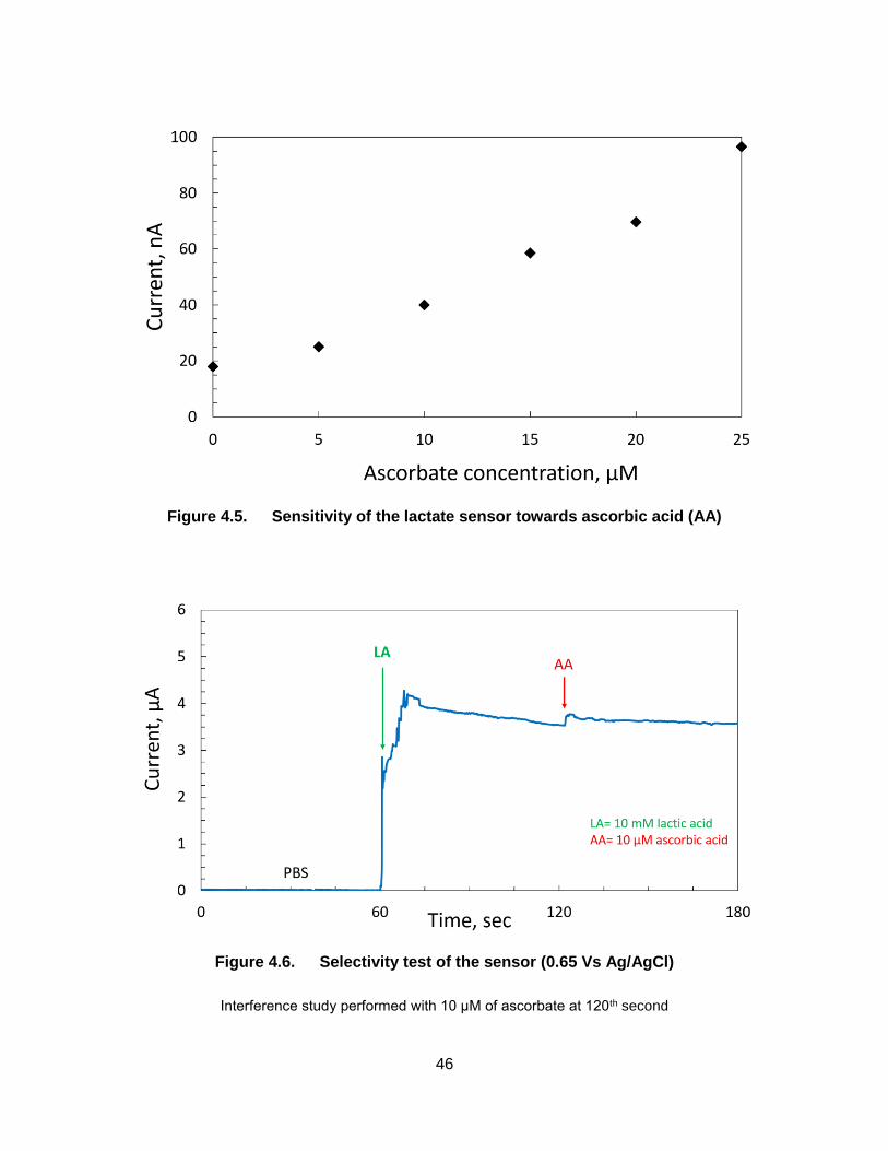
46
Figure 4.5. Sensitivity of the lactate sensor towards ascorbic acid (AA)
Figure 4.6. Selectivity test of the sensor (0.65 Vs Ag/AgCl)
Interference study performed with 10 μM of ascorbate at 120th second
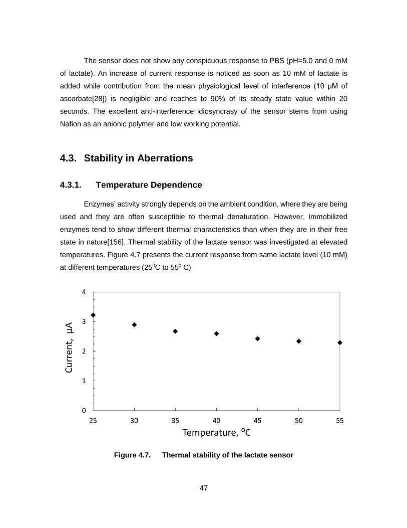
47
The sensor does not show any conspicuous response to PBS (pH=5.0 and 0 mM
of lactate). An increase of current response is noticed as soon as 10 mM of lactate is
added while contribution from the mean physiological level of interference (10 μM of
ascorbate[28]) is negligible and reaches to 90% of its steady state value within 20
seconds. The excellent anti-interference idiosyncrasy of the sensor stems from using
Nafion as an anionic polymer and low working potential.
4.3. Stability in Aberrations
4.3.1. Temperature Dependence
Enzymes’ activity strongly depends on the ambient condition, where they are being
used and they are often susceptible to thermal denaturation. However, immobilized
enzymes tend to show different thermal characteristics than when they are in their free
state in nature[156]. Thermal stability of the lactate sensor was investigated at elevated
temperatures. Figure 4.7 presents the current response from same lactate level (10 mM)
at different temperatures (250C to 550 C).
Figure 4.7. Thermal stability of the lactate sensor

48
According to Arrhenius law, temperature increase should increase the reaction rate
as long as the enzyme is not denatured at elevated temperatures. Temperature
dependency of the enzyme typically produces a bell shaped curve[157]. Although
significant drop in response is observed between 250C and 550 C (~ 28.86%), the drop of
response in the physiological temperature range between 350C and 400 C is insignificant
(~ 2.84%). The drop in response could be attributed to the enzyme’s thermal denaturation.
4.3.2. Bending Test
Wearable conformal sensors on epidermis are expected to be experiencing regular
mechanical deformation due to movements of human body. Hence these sensors
constantly need to prove their robustness against these distortions. AgNP-based stamped
electrodes have been shown to be stretched up to 20% strain with insignificant change in
electrical performance37. To observe its performance against mechanical deformations,
the developed lactate sensor was subjected to mechanical bending with different
curvature values.
Figure 4.8. Response of the lactate sensor vs bending curvature
(Inset: sensor under bending with 0.1 mm-1)

49
Figure 4.8 represents the sensor’s behavior in response to different bending
curvatures. The maximum deviation was noticed to be only 9.08% at 0.2 mm-1. This
excellent bendability of the sensor is the result of the cross-serpentine structure with
relatively smaller cross-sectional area of the fabricated thin-film-electrodes. The sensor’s
electrical performance was also checked and the resistance change has been noticed as
only 2.55% at 0.1 mm-1 of curvature with inward bending and 3.55% with outward bending.
A repeatedly bendable paper touch pad has been reported recently using stamping
technique with AgNPs[158]. The sensor was bent repeatedly to 8 mm of bending radius
at 1 Hz for 10,000 cycles and no significant change in electrical performance was noticed.
The excellent bendability of the sensor could be attributed to the compressive force
applied during stamping and the capillary force associated during the pattern transfer
process.
4.4. Wireless Transmission of Sensor Response
I want to thank Yue Dong for his huge assistance, contribution and support to
design and test the wireless transmission system for the sensor. To improve the portability
of the sensor to be used on human skin for continuous lactate measurement, an NFC-
based (near-field-communication) wireless transmission system has been demonstrated.
Electrochemical sensing output was in the form of current with an order of 10-6 (μA). A
transimpedance amplifier (OPA380) with low input impedance and high output impedance
was used in the current-signal conditioning path to covert the current into voltage. . A16-
bit microcontroller (MSP430g2553) with 10-bit internal ADC was used for signal
processing. The converted voltage was amplified with a 660KΩ feedback resistor.
Microcontroller collects data and sends a package to NFC module via UART port. Two
PN532 NFC modules were used to exchange data wirelessly.
The wireless transmission scheme is illustrated in Figure 4.9. The analog voltage
is swept by the internal DAC from MCU. This voltage is crossed between working and
reference electrode, causing a redox current at surface of working electrode. Analog
current is first converted to analog voltage since most ADCs cannot capture current signal.
This is achieved by a transimpedance amplifier with gain of 10M. In the transimpedance
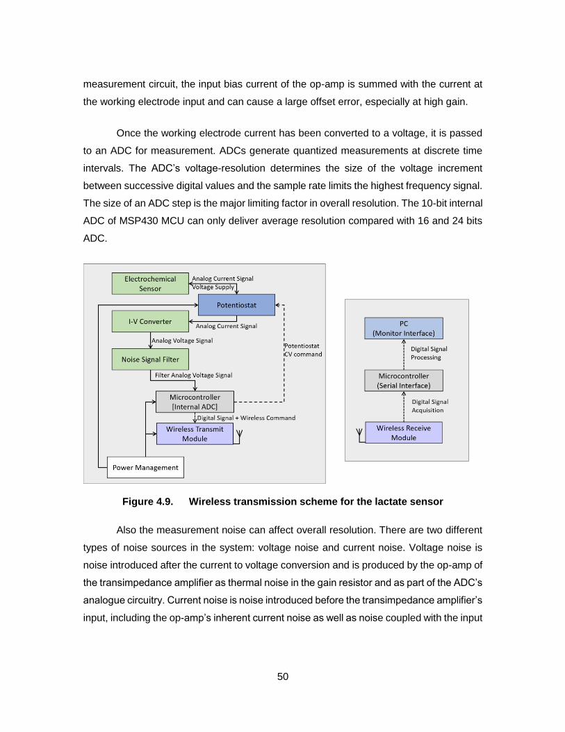
50
measurement circuit, the input bias current of the op-amp is summed with the current at
the working electrode input and can cause a large offset error, especially at high gain.
Once the working electrode current has been converted to a voltage, it is passed
to an ADC for measurement. ADCs generate quantized measurements at discrete time
intervals. The ADC’s voltage-resolution determines the size of the voltage increment
between successive digital values and the sample rate limits the highest frequency signal.
The size of an ADC step is the major limiting factor in overall resolution. The 10-bit internal
ADC of MSP430 MCU can only deliver average resolution compared with 16 and 24 bits
ADC.
Figure 4.9. Wireless transmission scheme for the lactate sensor
Also the measurement noise can affect overall resolution. There are two different
types of noise sources in the system: voltage noise and current noise. Voltage noise is
noise introduced after the current to voltage conversion and is produced by the op-amp of
the transimpedance amplifier as thermal noise in the gain resistor and as part of the ADC’s
analogue circuitry. Current noise is noise introduced before the transimpedance amplifier’s
input, including the op-amp’s inherent current noise as well as noise coupled with the input

51
line from external sources. Current noise is amplified by the transimpedance amplifier and
its contribution to the output noise is therefore proportional to the gain.
NFC transmitter wirelessly transmits the data package with encoded ADC values
to NFC receiver at 2Hz. MSP430 microcontroller is connected to NFC receiver to decipher
the values. The received data package was finally decoded by it, to acquire digital data on
PC via serial communication interface with the help of MATLAB. Figure 4.10.(A)
represents the response of the sensor acquired from NFC module for lactate solutions
with different concentrations. It shows distinctive rise in response according to the
increase in lactate concentration and sensor recovery time recorded was less than 2
seconds.
Figure 4.10. Wireless transmission system of the sensor
(A) Sensor, signal processing unit and NFC transceiver module (B) Response of the sensor transferred by NFC wireless system

52
Chapter 5. Conclusion and Future Works
5.1. Conclusion
The main purpose of this work was to investigate and demonstrate the use of silver
nanoparticle to fabricate flexible amperometric biosensor for noninvasive continuous
lactate measurement and its possibility to be used as wearable sensor using human
perspiration.
Electrode fabrication:
The first experimental chapter (Chapter 2) describes the steps followed towards
the development of the concept and fabrication of flexible sensing platform for lactate
monitoring. All three electrodes were fabricated in cross-serpentine pattern on PET
substrate using silver nanoparticle for high bendability, conformability and low impedance.
Simple spraying and stamping technique was employed for electrode fabrication and a UV
curable polymer (PU)-assisted pattern transfer protocol was followed.
Electrode modification:
Different modification steps for working and reference electrodes carried out are
outlined in chapter 3. Nafion was used as a membrane against anionic interferences such
as ascorbate and the sensor shows brilliant selectivity. No significant response was
observed in electrochemical response from interference. Lactate oxidase, as an enzyme
to break down lactate into pyruvate and hydrogen peroxide, was immobilized on the top
of Nafion layer using BSA as immobilizing agent and Glutaraldehyde as cross-linker.
Chloridization of the AgNPs was carried out by regular household bleach and the modified
pseudo reference electrode demonstrates longtime potential stability.
In-vitro performance:
The in-vitro tests were performed and a linear calibration curve was observed for
physiological relevant lactate concentration in sweat between 0 mM and 25 mM with

53
excellent coefficient of determination of 0.9732 and the sensitivity of the sensor was
calculated as 256 nA mM-1 cm-2.
Performance at different conditions:
The biosensor shows negligible shift in response in physiological temperature
range. Bending test was performed on the sensor and it demonstrates the reasoning
behind using cross-serpentine shaped electrodes as the sensor shows insignificant
change in response when it was bent at different curvatures. The sensor shows trifling
change in resistance upon bending.
Wireless transmission:
An NFC-based wireless transmission system has been developed and
demonstrated for easy wearability and continuous lactate measurement.
5.2. Future Works
This work was an attempt as to demonstrate the possibility of using silver
nanoparticle for non-invasive wearable lactate sensor. Significant possible improvements
could be suggested to optimize enzyme immobilization, stretchability, biocompatibility,
means to wearability and better selectivity.
Flexibility:
PET, as a flexible substrate was used for the sensor which is bendable but not
stretchable. Polydimethylsiloxane (PDMS) or Ecoflex could be utilized for the substrate to
be stretchable.
Practical approach to use the sensor on human epidermis:
A sterile gauze could be used as absorbent to sop up sweat and direct from
collecting to sensing area of the sensor[159]. For sticking the sensor to human skin, a
medical grade adhesive could be applied[160].
54
Outer protective membrane:
Wearable sensors should be able to reflect the analyte concentration over long
period of time. However stacks of different functional materials such as immobilized
enzyme and Nafion, are subjected to periodic decay. Further modification of the sensor
with biocompatible outer layer such as Chitosan would not only improve the reusability of
the sensor but also block other interferences, control diffusion of lactate flux and be the
potential candidate to touch the epidermis for continuous lactate measurement using
human perspiration. [92] [161].
Improved interference rejection at lower potential:
A great drawback of detecting hydrogen peroxide in lactate sensors as presented
in this work is the high over potential needed for hydrogen peroxide oxidation (~0.7 V) at
which many electroactive substances tend to oxidize to give interfering signals. The
detection of hydrogen peroxide should be carried out at low potential in order to reduce
the interference from other easily oxidizable species[162]. [163] [164] [165] [166]. While
exhibiting good sensitivity and accuracy, this approach suffers from other shortcomings
such as high cost, low stability and limited binding to sild surface (poor immobilization of
enzyme). Electrochemical organic mediators have been extensively studied, preferred
and used lately for oxidase-based biosensors[167] [168] [169]. Hexacyanoferrates and in
particular Prussian Blue (PB) has proved its ability to reduce hydrogen peroxide at a very
low potential (~0.0 V) and thus found a prominent use[170] [171] [172].
Membrane for improved lactate sensitivity with lower interference:
Nafion was used as an anionic polymer to block interferences for the lactate
sensor. Favorable effect for high lactate sensitivity and low response to interference could
be achieved by a combined film of Nafion and cellulose acetate[87].

55
References
[1] R. M. C. Dawson, D. C. Elliott, W. H. Elliott, and K. M. Jones, “Data for biochemical research,” 1986.
[2] G. Burrell, “Lactic Acid Doesn’t Cause Muscle Pain,” The Science Explorer, 2015. [Online]. Available: http://thescienceexplorer.com/brain-and-body/lactic-acid-doesn-t-cause-muscle-pain.
[3] H. Lodish, A. Berk, P. Matsudaira, C. A. Kaiser, M. Krieger, M. P. Scott, L. Zipursky, and J. Darnell, Molecular Cell Biology, vol. 4. 2008.
[4] J. M. Berg, J. L. Tymoczko, and L. Stryer, Biochemistry, 6th ed. W. H. Freeman, 2006.
[5] H. Pelicano, D. S. Martin, R.-H. Xu, and P. Huang, “Glycolysis inhibition for anticancer treatment.,” Oncogene, vol. 25, no. 34, pp. 4633–46, 2006.
[6] B. Alberts, A. Johnson, J. Lewis, M. Raff, K. Roberts, and P. Walter, Molecular Biology of the Cell, Fourth Edition. 2002.
[7] M. M. Cox and D. L. Nelson, Lehninger Principles of Biochemistry, vol. 2, no. 3174. 1921.
[8] M. R. Romero, F. Ahumada, F. Garay, and A. M. Baruzzi, “Amperometric biosensor for direct blood lactate detection,” Anal. Chem., vol. 82, no. 13, pp. 5568–5572, 2010.
[9] D. De Backer, J. Creteur, H. Zhang, M. Norrenberg, and J. L. Vincent, “Lactate production by the lungs in acute lung injury,” Am. J. Respir. Crit. Care Med., vol. 156, no. 4 I, pp. 1099–1104, 1997.
[10] J. a Kruse, S. a Zaidi, and R. W. Carlson, “Significance of blood lactate levels in critically ill patients with liver disease.,” Am. J. Med., vol. 83, no. 1, pp. 77–82, 1987.
[11] R. Bellomo, “Bench-to-bedside review: lactate and the kidney.,” Crit. Care, vol. 6, no. 4, pp. 322–6, 2002.
[12] J. Karlsson, J. T. Willerson, S. J. Leshin, C. B. Mullins, and J. H. Mitchell, “Skeletal muscle metabolites in patients with cardiogenic shock or severe congestive heart failure,” Scand. J. Clin. Lab. Investig., vol. 35, no. 1, pp. 73–79, 1975.
[13] R. A. Gatenby and R. J. Gillies, “Why do cancers have high aerobic glycolysis?,” Nat. Rev. Cancer, vol. 4, no. 11, pp. 891–899, 2004.
56
[14] R. a Gatenby and R. J. Gillies, “Glycolysis in cancer: a potential target for therapy.,” Int. J. Biochem. Cell Biol., vol. 39, no. 7–8, pp. 1358–1366, 2007.
[15] A. Stekelenburg, D. Gawlitta, D. L. Bader, and C. W. Oomens, “Deep Tissue Injury: How Deep is Our Understanding?,” Arch. Phys. Med. Rehabil., vol. 89, no. 7, pp. 1410–1413, 2008.
[16] D. Gawlitta, C. W. J. Oomens, D. L. Bader, F. P. T. Baaijens, and C. V. C. Bouten, “Temporal differences in the influence of ischemic factors and deformation on the metabolism of engineered skeletal muscle.,” J. Appl. Physiol., vol. 103, no. 2, pp. 464–73, 2007.
[17] D. A. Sakharov, M. U. Shkurnikov, M. Y. Vagin, E. I. Yashina, A. A. Karyakin, and A. G. Tonevitsky, “Relationship between lactate concentrations in active muscle sweat and whole blood,” Bull. Exp. Biol. Med., vol. 150, no. 1, pp. 83–85, 2010.
[18] A. Poscia, D. Messeri, D. Moscone, F. Ricci, and F. Valgimigli, “A novel continuous subcutaneous lactate monitoring system,” in Biosensors and Bioelectronics, 2005, vol. 20, no. 11, pp. 2244–2250.
[19] O. N. Okorie and P. Dellinger, “Lactate: Biomarker and Potential Therapeutic Target,” Critical Care Clinics, vol. 27, no. 2. pp. 299–326, 2011.
[20] L. A. S. Nunes and D. Vaz de Macedo, “Saliva as a Diagnostic Fluid in Sports Medicine : Potential and Limitations,” J Bras Patol Med Lab, vol. 49, no. 4, pp. 247–255, 2013.
[21] D. a MacLean, J. Bangsbo, and B. Saltin, “Muscle interstitial glucose and lactate levels during dynamic exercise in humans determined by microdialysis.,” J. Appl. Physiol., vol. 87, no. 4, pp. 1483–1490, 1999.
[22] N. Thomas, I. Lähdesmäki, and B. A. Parviz, “A contact lens with an integrated lactate sensor,” Sensors Actuators, B Chem., vol. 162, no. 1, pp. 128–134, 2012.
[23] E. M. Marek, J. Volke, I. Hawener, P. Platen, K. Mückenhoff, and W. Marek, “Measurements of lactate in exhaled breath condensate at rest and after maximal exercise in young and healthy subjects.,” J. Breath Res., vol. 4, no. 1, p. 017105, 2010.
[24] S. Biagi, S. Ghimenti, M. Onor, and E. Bramanti, “Simultaneous determination of lactate and pyruvate in human sweat using reversed-phase high-performance liquid chromatography: A noninvasive approach,” Biomed. Chromatogr., vol. 26, no. 11, pp. 1408–1415, 2012.
[25] P. J. Derbyshire, H. Barr, F. Davis, and S. P. J. Higson, “Lactate in human sweat: A critical review of research to the present day,” Journal of Physiological Sciences, vol. 62, no. 6. pp. 429–440, 2012.

57
[26] S. Coyle, F. Benito-Lopez, R. Byrne, and D. Diamond, “On-body chemical sensors for monitoring sweat,” in Lecture Notes in Electrical Engineering, 2010, vol. 75 LNEE, pp. 177–193.
[27] O. P. Kreyden and E. P. Scheidegger, “Anatomy of the sweat glands, pharmacology of botulinum toxin, and distinctive syndromes associated with hyperhidrosis,” Clinics in Dermatology, vol. 22, no. 1. pp. 40–44, 2004.
[28] A. B. Stefaniak and C. J. Harvey, “Dissolution of materials in artificial skin surface film liquids,” Toxicology in Vitro, vol. 20, no. 8. pp. 1265–1283, 2006.
[29] C. J. Harvey, R. F. LeBouf, and A. B. Stefaniak, “Formulation and stability of a novel artificial human sweat under conditions of storage and use,” Toxicol. Vitr., vol. 24, no. 6, pp. 1790–1796, 2010.
[30] K. Sato and R. L. Dobson, “Glucose metabolism of the isolated eccrine sweat gland. II. The relation between glucose metabolism and sodium transport,” J. Clin. Invest., vol. 52, no. 9, pp. 2166–2174, 1973.
[31] J. M. Green, R. C. Pritchett, T. R. Crews, J. R. McLester, and D. C. Tucker, “Sweat lactate response between males with high and low aerobic fitness,” Eur. J. Appl. Physiol., vol. 91, no. 1, pp. 1–6, 2004.
[32] P. Pilardeau, J. Vaysse, M. Garnier, M. Joublin, and L. Valeri, “Secretion of eccrine sweat glands during exercise,” Br J Sport. Med., vol. 13, no. 3, pp. 118–121, 1979.
[33] A. Polliack, R. Taylor, and D. Bader, “Sweat analysis following pressure ischaemia in a group of debilitated subjects,” J. Rehabil. Res. Dev., vol. 34, no. 3, pp. 303–308, 1997.
[34] J. Bijman and P. M. Quinton, “Lactate and Bicarbonate Uptake in the Sweat Duct of Cystic Fibrosis and Normal Subjects,” Pediatr. Res., vol. 21, no. 1, pp. 79–82, 1987.
[35] P. Kukumberg, P. Valkovic, P. Blazicek, A. Guth, J. Martinkova, V. Provaznik, and F. Jagla, “Sweat: A potential marker of clinical activity in panic disorder,” Neuroendocrinol. Lett., vol. 30, no. 3, pp. 400–402, 2009.
[36] O. Laccourreye, D. Bernard, O. De Lacharriere, R. Bazin, and D. Brasnu, “Frey’s syndrome analysis with biosensor: A preliminary study,” Arch. Otolaryngol. - Head Neck Surg., vol. 119, no. 9, pp. 940–944, 1993.
[37] W. Jia, A. J. Bandodkar, G. Valdés-Ramírez, J. R. Windmiller, Z. Yang, J. Ramírez, G. Chan, and J. Wang, “Electrochemical tattoo biosensors for real-time noninvasive lactate monitoring in human perspiration,” Anal. Chem., vol. 85, no. 14, pp. 6553–6560, 2013.
58
[38] R. Zaydan, M. Dion, and M. Boujtita, “Development of a New Method, Based on a Bioreactor Coupled with an L-Lactate Biosensor, toward the Determination of a Nonspecific Inhibition of L-Lactic Acid Production during Milk Fermentation,” J. Agric. Food Chem., vol. 52, no. 1, pp. 8–14, 2004.
[39] P. Urban and F. Lederer, “Inactivation of flavocytochrome b2 with fluoropyruvate. Reaction at the active-site histidine,” Eur J Biochem, vol. 173, no. 1, pp. 155–162, 1988.
[40] D. Harvey, “Reference Electrodes,” ASDL Community, 2013. [Online]. Available: http://community.asdlib.org/imageandvideoexchangeforum/2013/07/31/reference-electrodes/.
[41] J. Kim and W. S. Kim, “A paired stretchable printed sensor system for ambulatory blood pressure monitoring,” Sensors Actuators A Phys., vol. 238, pp. 329–336, 2016.
[42] J. Viventi, D.-H. Kim, L. Vigeland, E. S. Frechette, J. a Blanco, Y.-S. Kim, A. E. Avrin, V. R. Tiruvadi, S.-W. Hwang, A. C. Vanleer, D. F. Wulsin, K. Davis, C. E. Gelber, L. Palmer, J. Van der Spiegel, J. Wu, J. Xiao, Y. Huang, D. Contreras, J. a Rogers, and B. Litt, “Flexible, foldable, actively multiplexed, high-density electrode array for mapping brain activity in vivo.,” Nat. Neurosci., vol. 14, no. 12, pp. 1599–605, 2011.
[43] D.-H. Kim, N. Lu, R. Ghaffari, Y.-S. Kim, S. P. Lee, L. Xu, J. Wu, R.-H. Kim, J. Song, Z. Liu, J. Viventi, B. de Graff, B. Elolampi, M. Mansour, M. J. Slepian, S. Hwang, J. D. Moss, S.-M. Won, Y. Huang, B. Litt, and J. A. Rogers, “Materials for multifunctional balloon catheters with capabilities in cardiac electrophysiological mapping and ablation therapy,” Nat. Mater., vol. 10, no. 4, pp. 316–23, 2011.
[44] J. Viventi, D.-H. Kim, J. D. Moss, Y.-S. Kim, J. A. Blanco, N. Annetta, A. Hicks, J. Xiao, Y. Huang, D. J. Callans, J. A. Rogers, and B. Litt, “A Conformal, Bio-Interfaced Class of Silicon Electronics for Mapping Cardiac Electrophysiology,” Sci. Transl. Med., vol. 2, no. 24, pp. 24ra22–24ra22, 2010.
[45] D.-H. Kim, N. Lu, R. Ma, Y.-S. Kim, R.-H. Kim, S. Wang, J. Wu, S. M. Won, H. Tao, A. Islam, K. J. Yu, T. Kim, R. Chowdhury, M. Ying, L. Xu, M. Li, H.-J. Chung, H. Keum, M. McCormick, P. Liu, Y.-W. Zhang, F. G. Omenetto, Y. Huang, T. Coleman, and J. A. Rogers, “Epidermal Electronics,” Science (80-. )., vol. 333, no. 6044, pp. 838–843, 2011.
[46] S. P. Lacour, S. Wagner, Z. Huang, and Z. Suo, “Stretchable gold conductors on elastomeric substrates,” Appl. Phys. Lett., vol. 82, no. 15, pp. 2404–2406, 2003.
[47] Y. Xiang, T. Li, Z. Suo, and J. J. Vlassak, “High ductility of a metal film adherent on a polymer substrate,” Appl. Phys. Lett., vol. 87, no. 16, pp. 1–3, 2005.

59
[48] J. A. Rogers, T. Someya, and Y. Huang, “Materials and Mechanics for Stretchable Electronics,” Science (80-. )., vol. 327, no. 5973, pp. 1603–1607, 2010.
[49] B. Y. Ahn, E. B. Duoss, M. J. Motala, X. Guo, S.-I. Park, Y. Xiong, J. Yoon, R. G. Nuzzo, J. a Rogers, and J. a Lewis, “Omnidirectional printing of flexible, stretchable, and spanning silver microelectrodes.,” Science, vol. 323, no. 5921, pp. 1590–3, 2009.
[50] K. S. Kim, Y. Zhao, H. Jang, S. Y. Lee, J. M. Kim, K. S. Kim, J.-H. Ahn, P. Kim, J.-Y. Choi, and B. H. Hong, “Large-scale pattern growth of graphene films for stretchable transparent electrodes.,” Nature, vol. 457, no. 7230, pp. 706–10, 2009.
[51] D. Y. Khang, J. Xiao, C. Kocabas, S. MacLaren, T. Banks, H. Jiang, Y. Y. Huango, and J. A. Rogers, “Molecular scale buckling mechanics in individual aligned single-wall carbon nanotubes on elastomeric substrates,” Nano Lett., vol. 8, no. 1, pp. 124–130, 2008.
[52] J. Kim and W. S. Kim, “Stretching Silver: Printed Metallic Nano Inks in Stretchable Conductor Applications,” IEEE Nanotechnol. Mag., vol. 8, no. 4, pp. 6–13, 2014.
[53] J. A. Rogers, Z. Bao, K. Baldwin, A. Dodabalapur, B. Crone, V. R. Raju, V. Kuck, H. Katz, K. Amundson, J. Ewing, and P. Drzaic, “Paper-like electronic displays: large-area rubber-stamped plastic sheets of electronics and microencapsulated electrophoretic inks.,” Proc. Natl. Acad. Sci. U. S. A., vol. 98, no. 9, pp. 4835–40, 2001.
[54] T. Rai, P. Dantes, B. Bahreyni, and W. S. Kim, “A stretchable RF antenna with silver nanowires,” IEEE Electron Device Lett., vol. 34, no. 4, pp. 544–546, 2013.
[55] T. Akter and W. S. Kim, “Reversibly Stretchable Transparent Conductive Coatings of Spray- Deposited Silver Nanowires(supporting),” ACS Appl. Mater. Interfaces, pp. 1–3, 2012.
[56] A. Kamyshny, J. Steinke, and S. Magdassi, “Metal-based Inkjet Inks for Printed Electronics,” Open Appl. Phys. J., vol. 4, pp. 19–36, 2011.
[57] S. H. Ko, I. Park, H. Pan, C. P. Grigoropoulos, A. P. Pisano, C. K. Luscombe, and J. M. J. Fréchet, “Direct nanoimprinting of metal nanoparticles for nanoscale electronics fabrication,” Nano Lett., vol. 7, no. 7, pp. 1869–1877, 2007.
[58] Y. Li, Y. Wu, and B. S. Ong, “Facile Synthesis of Silver Nanoparticles Useful for Fabrication of High-Conductivity Elements for Printed Electronics,” J. Am. Chem. Soc., vol. 127, no. 10, pp. 3266–3267, 2005.
[59] J. Kim, K. Wubs, B.-S. Bae, and W. Soo Kim, “Direct stamping of silver nanoparticles toward residue-free thick electrode,” Sci. Technol. Adv. Mater., vol. 13, no. 3, p. 035004, 2012.

60
[60] D. Y. Choi, H. W. Kang, H. J. Sung, and S. S. Kim, “Annealing-free, flexible silver nanowire-polymer composite electrodes via a continuous two-step spray-coating method.,” Nanoscale, vol. 5, no. 3, pp. 977–83, 2013.
[61] J. S. Park, M. Rezaei, and W. S. Kim, “Sustained percolation in stretched silver nanowire networks for stretchable inter-connection applications,” Adv. Eng. Mater., vol. 16, no. 7, pp. 905–908, 2014.
[62] H. Lee, I. Kim, M. Kim, and H. Lee, “Moving beyond flexible to stretchable conductive electrodes using metal nanowires and graphenes,” Nanoscale, vol. 8, no. 4, pp. 1789–1822, 2016.
[63] X. Yang, J. Bai, Y. Wang, X. Jiang, and X. He, “Hydrogen peroxide and glucose biosensor based on silver nanowires synthesized by polyol process,” Analyst, vol. 137, no. 18, p. 4362, 2012.
[64] Y. Lin, P. Yu, J. Hao, Y. Wang, T. Ohsaka, and L. Mao, “Continuous and Simultaneous Electrochemical Measurements of Glucose, Lactate, and Ascorbate in Rat Brain Following Brain Ischemia,” Anal. Chem., vol. 86, no. 8, pp. 3895–3901, 2014.
[65] Y. T. Wang, L. Yu, J. Wang, L. Lou, W. J. Du, Z. Q. Zhu, H. Peng, and J. Z. Zhu, “A novel L-lactate sensor based on enzyme electrode modified with ZnO nanoparticles and multiwall carbon nanotubes,” J. Electroanal. Chem., vol. 661, no. 1, pp. 8–12, 2011.
[66] Z. H. Ibupoto, S. M. U. A. Shah, K. Khun, and M. Willander, “Electrochemical L-lactic acid sensor based on immobilized ZnO nanorods with lactate oxidase,” Sensors, vol. 12, no. 3, pp. 2456–2466, 2012.
[67] M. D. Rubianes and G. A. Rivas, “Enzymatic biosensors based on carbon nanotubes paste electrodes,” Electroanalysis, vol. 17, no. 1, pp. 73–78, 2005.
[68] J. M. Goran, J. L. Lyon, and K. J. Stevenson, “Amperometric detection of l-lactate using nitrogen-doped carbon nanotubes modified with lactate oxidase,” Anal. Chem., vol. 83, no. 21, pp. 8123–8129, 2011.
[69] B. K. Jena and C. R. Raj, “Electrochemical biosensor based on integrated assembly of dehydrogenase enzymes and gold nanoparticles,” Anal. Chem., vol. 78, no. 18, pp. 6332–6339, 2006.
[70] M. Yang, J. Wang, H. Li, J.-G. Zheng, and N. Nick Wu, “A lactate electrochemical biosensor with a titanate nanotube as direct electron transfer promoter.,” Nanotechnology, vol. 19, no. 7, p. 075502, 2008.
[71] D. Manno, E. Filippo, M. Di Giulio, and A. Serra, “Synthesis and characterization of starch-stabilized Ag nanostructures for sensors applications,” J. Non. Cryst. Solids,

61
vol. 354, no. 52–54, pp. 5515–5520, 2008.
[72] X. Ren, X. Meng, D. Chen, F. Tang, and J. Jiao, “Using silver nanoparticle to enhance current response of biosensor,” Biosens. Bioelectron., vol. 21, no. 3, pp. 433–437, 2005.
[73] Q. Wang and J. Zheng, “Electrodeposition of silver nanoparticles on a zinc oxide film: Improvement of amperometric sensing sensitivity and stability for hydrogen peroxide determination,” Microchim. Acta, vol. 169, no. 3, pp. 361–365, 2010.
[74] Z. J. Chen, X. M. Ou, F. Q. Tang, and L. Jiang, “Effect of nanometer particles on the adsorbability and enzymatic activity of glucose oxidase,” Colloids Surfaces B Biointerfaces, vol. 7, no. 3–4, pp. 173–179, 1996.
[75] W. H. Yeo, Y. S. Kim, J. Lee, A. Ameen, L. Shi, M. Li, S. Wang, R. Ma, S. H. Jin, Z. Kang, Y. Huang, and J. A. Rogers, “Multifunctional epidermal electronics printed directly onto the skin,” Adv. Mater., vol. 25, no. 20, pp. 2773–2778, 2013.
[76] Y. Kim, J. Zhu, B. Yeom, M. Di Prima, X. Su, J.-G. Kim, S. J. Yoo, C. Uher, and N. a Kotov, “Stretchable nanoparticle conductors with self-organized conductive pathways,” Nature, vol. 500, no. 7460, pp. 59–63, 2013.
[77] C. Kim, M. Nogi, K. Suganuma, Y. Saitou, and J. Shirakami, “Absorption layers of ink vehicles for inkjet-printed lines with low electrical resistance,” RSC Adv., vol. 2, no. 22, p. 8447, 2012.
[78] Y. Wyser, C. Pelletier, and J. Lange, “Predicting and determining the bending stiffness of thin films and laminates,” Packag. Technol. Sci., vol. 14, no. 3, pp. 97–108, 2001.
[79] J. Kim, Z. Wang, and W. S. Kim, “Stretchable RFID for wireless strain sensing with silver nano ink,” IEEE Sens. J., vol. 14, no. 12, pp. 4395–4401, 2014.
[80] S. Chung, J. Lee, H. Song, S. Kim, J. Jeong, and Y. Hong, “Inkjet-printed stretchable silver electrode on wave structured elastomeric substrate,” Appl. Phys. Lett., vol. 98, no. 15, 2011.
[81] K.-S. Kim, K.-H. Jung, and S.-B. Jung, “Design and fabrication of screen-printed silver circuits for stretchable electronics,” Microelectron. Eng., vol. 120, pp. 216–220, 2014.
[82] H. Ju, X. Zhang, and J. Wang, “Carbon Nanofiber-Based Nanocomposites for Biosensing,” in NanoBiosening Principles, Development and Application, Biological and Medical Physics, Biomedical Engineering, Springer, p. 157.
[83] D. Carelli, D. Centonze, C. Palermo, M. Quinto, and T. Rotunno, “An interference free amperometric biosensor for the detection of biogenic amines in food products,”
62
Biosens. Bioelectron., vol. 23, no. 5, pp. 640–647, 2007.
[84] F. K. Sartain, X. Yang, and C. R. Lowe, “Holographic Lactate Sensor,” Anal. Chem., vol. 78, no. 16, pp. 5664–5670, 2006.
[85] K. Wang, J.-J. Xu, and H.-Y. Chen, “Biocomposite of cobalt phthalocyanine and lactate oxidase for lactate biosensing with MnO2 nanoparticles as an eliminator of ascorbic acid interference,” Sensors Actuators B Chem., vol. 114, no. 2, pp. 1052–1058, 2006.
[86] R. Maidan and A. Heller, “Elimination of Electrooxidizable Interferants in Glucose Electrodes,” J. Am. Chem. Soc., vol. 113, no. 23, pp. 9003–9004, 1991.
[87] Y. Zhang, Y. Hu, G. S. Wilson, D. Moatti-Sirat, V. Poitout, and G. Reach, “Elimination of the acetaminophen interference in an implantable glucose sensor.,” Anal. Chem., vol. 66, no. 7, pp. 1183–1188, 1994.
[88] G. Gebel, “Structural evolution of water swollen perfluorosulfonated ionomers from dry membrane to solution,” Polymer (Guildf)., vol. 41, no. 15, pp. 5829–5838, 2000.
[89] S. Schlick, Ed., Ionomers: Characterization, Theory, and Applications. CRC Press, 1996.
[90] C. Heitner-Wirguin, “Recent advances in perfluorinated ionomer membranes: Structure, properties and applications,” Journal of Membrane Science, vol. 120, no. 1. pp. 1–33, 1996.
[91] G. J. Elfring and H. Struchtrup, “Thermodynamic considerations on the stability of water in Nafion,” J. Memb. Sci., vol. 297, no. 1–2, pp. 190–198, 2007.
[92] A. Cavallini, G. Micheli, and S. Carrara, “Comparison of three methods of biocompatible multi-walled carbon nanotubes confinement for the development of implantable amperometric adenosine-5’-triphosphate biosensors,” Sens. Lett., vol. 9, no. 5, pp. 1838–1844, 2011.
[93] W. Lee, “Electrochemical Biosensors Based on Carbon Nanotubes,” in Smart Biosensor Technology, G. K. Knopf and A. S. Bassi, Eds. CRC Press, Taylor & Francis Group, 2007, pp. 335–351.
[94] F. Du, W. Huang, Y. Shi, Z. Wang, and J. Cheng, “Real-time monitoring of NO release from single cells using carbon fiber microdisk electrodes modified with single-walled carbon nanotubes,” Biosens. Bioelectron., vol. 24, no. 3, pp. 415–21, 2008.
[95] X. Zhang, Y. Kislyak, J. Lin, A. Dickson, L. Cardosa, M. Broderick, and H. Fein, “Nanometer size electrode for nitric oxide and S-nitrosothiols measurement,” in Electrochemistry Communications, 2002, vol. 4, no. 1, pp. 11–16.

63
[96] L. Yang, X. Ren, F. Tang, and L. Zhang, “A practical glucose biosensor based on Fe3O4 nanoparticles and chitosan/nafion composite film,” Biosens. Bioelectron., vol. 25, no. 4, pp. 889–895, 2009.
[97] N. G. Patel, A. Erlenkötter, K. Cammann, and G. C. Chemnitius, “Fabrication and characterization of disposable type lactate oxidase sensors for dairy products and clinical analysis,” Sensors Actuators, B Chem., vol. 67, no. 1, pp. 134–141, 2000.
[98] T. Tsuchida and K. Yoda, “Multi-Enzyme Membrane Electrodes for Determination of Creatinine and Creatinein Serum,” Clin. Chem., vol. 29, no. 1, pp. 51–55, 1983.
[99] M. Mascini and F. Mazzei, “Amperometric sensor for pyruvate with immobilized pyruvate oxidase,” Anal. Chim. Acta, vol. 192, no. C, pp. 9–16, 1987.
[100] D. S. Bindra, Y. Zhang, G. S. Wilson, R. Sternberg, D. R. Thévenot, D. Moatti, and G. Reach, “Design and in vitro studies of a needle-type glucose sensor for subcutaneous monitoring,” Anal. Chem., vol. 63, no. 17, pp. 1692–6, 1991.
[101] T. Tsuchida and K. Yoda, “Immobilization of D-glucose oxidase onto a hydrogen peroxide permselective membrane and application for an enzyme electrode,” Enzyme Microb. Technol., vol. 3, no. 4, pp. 326–330, Oct. 1981.
[102] Ms Cooper’s A level Biology, “A level. S.5 Immobilisation of enzymes Ms Cooper,” 2014. [Online]. Available: https://www.youtube.com/watch?v=f163ohXmKEI.
[103] M. A. Khan, A. A. Al-Jalal, and I. A. Bakhtiari, “‘Decoking’ of a ‘coked’ zeolite catalyst in a glow discharge,” Anal. Bioanal. Chem., vol. 377, no. 1, pp. 89–96, 2003.
[104] R. Fernández-Lafuente, V. Rodriguez, and J. M. Guisan, “The coimmobilization of D-amino acid oxidase and catalase enables the quantitative transformation of D-amino acids (D-phenylalanine) into ??-keto acids (phenylpyruvic acid),” Enzyme Microb. Technol., vol. 23, no. 1–2, pp. 28–33, 1998.
[105] M. N. Gupta, “Thermostabilization of proteins,” Biotechnol. Appl. Biochem., vol. 14, no. 1, pp. 1–11.
[106] R. A. Messing, “Adsorption and Inorganic Bridge Formations,” Methods Enzymol., vol. 44, pp. 148–169, 1976.
[107] M. B. Beatriz and F. Batista-Viera, “Immobilization of enzymes: A literature survey,” Immobil. Enzym. Cells Third Ed., vol. 1051, pp. 15–31, 2013.
[108] K. F. O’Driscoll, “Techniques of Enzyme Entrapment in Gels,” Methods Enzymol., vol. 44, no. C, pp. 169–183, 1976.
[109] V. Kandimalla, V. Tripathi, and H. Ju, “Immobilization of Biomolecules in Sol–Gels: Biological and Analytical Applications,” Crit. Rev. Anal. Chem., vol. 36, no. 2, pp.

64
73–106, 2006.
[110] M. Ciureanu, S. Goldstein, and M. A. Mateescu, “Direct Electron Transfer for Hemoglobin in Surfactant Films Cast on Carbon Electrodes,” J. Electrochem. Soc., vol. 145, no. 2, pp. 533–541, 1998.
[111] H. Sun, N. Hu, and H. Ma, “Direct Electrochemistry of Hemoglobin in Polyacrylamide Hydrogel Films on Pyrolytic Graphite Electrodes,” Electroanalysis, vol. 12, no. 13, pp. 1064–1070, 2000.
[112] J. Yang, N. Hu, and J. F. Rusling, “Enhanced electron transfer for hemoglobin in poly (ester sulfonic acid) films on pyrolytic graphite electrodes,” J. Electroanal. Chem., vol. 463, no. 1, pp. 53–62, 1999.
[113] Q. Huang, Z. Lu, and J. F. Rusling, “Composite Films of Surfactants, Nafion, and Proteins with Electrochemical and Enzyme Activity,” Langmuir, vol. 12, no. 22, pp. 5472–5480, 1996.
[114] B. C. Dave, B. Dunn, J. S. Valentine, and J. I. Zink, “Sol-gel encapsulation methods for biosensors,” Anal. Chem., vol. 66, no. 22, p. 1120A–1127A, 1994.
[115] D. Avnir, S. Braun, O. Lev, and M. Ottolenghi, “Enzymes and Other Proteins Entrapped in Sol-Gel Materials,” Chem. Mater., vol. 6, no. 12, pp. 1605–1614, 1994.
[116] H. H. Weetall, “Preparation of immobilized proteins covalently coupled through silane coupling agents to inorganic supports,” Appl. Biochem. Biotechnol., vol. 41, no. 3, pp. 157–188, 1993.
[117] A. S. M. Chong and X. S. Zhao, “Design of large-pore mesoporous materials for immobilization of penicillin G acylase biocatalyst,” in Catalysis Today, 2004, vol. 93–95, pp. 293–299.
[118] J. Deere, E. Magner, J. G. Wall, and B. K. Hodnett, “Adsorption and activity of proteins onto mesoporous silica,” Catal. Letters, vol. 85, no. 1–2, pp. 19–23, 2003.
[119] M. E. Gimon-Kinsel, V. L. Jimenez, L. Washmon, and J. J. Balkus, “Mesoporous molecular sieve immobilized enzymes.,” Stud. Surf. Sci. Catal., vol. 117, no. Mesoporous Molecular Sieves 1998, pp. 373–380, 1998.
[120] Z. Dai, K. Liu, Y. Tang, X. Yang, J. Bao, and J. Shen, “A novel tetragonal pyramid-shaped porous ZnO nanostructure and its application in the biosensing of horseradish peroxidase,” J. Mater. Chem., vol. 18, no. 16, pp. 1919–1926, 2008.
[121] H. H. P. Yiu, P. A. Wright, and N. P. Botting, “Enzyme immobilisation using siliceous mesoporous molecular sieves,” Microporous Mesoporous Mater., vol. 44–45, pp. 763–768, 2001.

65
[122] J. Lee, D. Lee, E. Oh, J. Kim, Y. P. Kim, S. Jin, H. S. Kim, Y. Hwang, H. K. Ja, J. G. Park, C. H. Shin, J. Kim, and T. Hyeon, “Preparation of a magnetically switchable bioelectrocatalytic system employing cross-linked enzyme aggregates in magnetic mesocellular carbon foam,” Angew. Chemie - Int. Ed., vol. 44, no. 45, pp. 7427–7432, 2005.
[123] R. R. V., Ed., Advances in Food Biotechnology. Wiley-Blackwell, 2015.
[124] F. A. Batzias, “Multicritera Choice of Enzyme Immobilization Process for BIosensor Design and Construction,” in Trends and Perspective in Modern Computational Science, 2006.
[125] H. H. Weetall, “Immobilized Enzymes:Analytical Application,” Anal. Chem., vol. 46, no. 7, p. 602A–615A, 1974.
[126] M. Ottesen and B. Svensson, “Modification of Papain by Treatment with Glutaraldehyde under Reducing and Non-reducing Conditions,” C. R. Trav. Lab. Carlsberg, vol. 38, no. 11, pp. 171–185, 1970.
[127] Y. Tomimatsu, E. F. Jansen, W. Gaffield, and A. C. Olson, “Physical chemical observations on the α-chymotrypsin glutaraldehyde system during formation of an insoluble derivative,” J. Colloid Interface Sci., vol. 36, no. 1, pp. 51–64, 1971.
[128] E. F. Jansen, Y. Tomimatsu, and A. C. Olson, “Cross-linking of α-chymotrypsin and other proteins by reaction with glutaraldehyde,” Arch. Biochem. Biophys., vol. 144, no. 1, pp. 394–400, 1971.
[129] O. R. Zaborsky, “Immobilized Enzymes—Miscellaneous Methods and General Classification,” Methods Enzymol., vol. 44, pp. 317–332, 1976.
[130] E. F. Jansen and A. C. Olson, “Properties and Enzymatic Activities of Papain Insolubilized with Glutaraldehyde,” Arch. Biochem. Biophys., vol. 129, no. 1, pp. 221–227, Jan. 1969.
[131] O. Barbosa, C. Ortiz, Á. Berenguer-Murcia, R. Torres, R. C. Rodrigues, and R. Fernandez-Lafuente, “Glutaraldehyde in bio-catalysts design: a useful crosslinker and a versatile tool in enzyme immobilization,” RSC Adv., vol. 4, no. 207890, pp. 1583–1600, 2014.
[132] I. Migneault, C. Dartiguenave, M. J. Bertrand, and K. C. Waldron, “Glutaraldehyde: Behavior in aqueous solution, reaction with proteins, and application to enzyme crosslinking,” Biotechniques, vol. 37, no. 5, pp. 790–802, 2004.
[133] G. A. Islan, Y. N. Martinez, A. Illanes, and G. R. Castro, “Development of novel alginate lyase cross-linked aggregates for the oral treatment of cystic fibrosis,” RSC Adv., vol. 4, no. 23, pp. 11758–11765, 2014.
66
[134] S. Chawla, J. Narang, and C. S. Pundir, “An amperometric polyphenol biosensor based on polyvinyl chloride membrane,” Anal. Methods, vol. 2, no. 8, pp. 1106–1111, 2010.
[135] C. G. C. Zoski, Handbook of Electrochemistry, vol. 5, no. 2. 2007.
[136] M. R. McAinsh and C. K.-Y. Ng, “Measurement of Cytosolic-Free Ca2+ in Plant Tissue,” in Calcium Signaling Protocols, D. G. Lambert, Ed. Totowa, NJ: Humana Press, 2005, pp. 289–302.
[137] P. Krishnan, S. E. Dryer, and P. E. Hardin, “Measuring Circadian Rhythms in Olfaction Using Electroantennograms,” Methods Enzymol., vol. 393, pp. 495–508, 2005.
[138] H. Kahlert, “Reference Electrodes,” in Electroanalytical Methods: Guide to Experiments and Applications, F. Scholz, Ed. Berlin, Heidelberg: Springer Berlin Heidelberg, 2002, pp. 261–278.
[139] A. J. Bard and L. R. Faulkner, Electrochemical Methods Fundamentals and Applications. Wiley, New York, NY, 2001.
[140] G. Inzelt, “Pseudo-reference Electrodes,” in Handbook of Reference Electrodes, G. Inzelt, A. Lewenstam, and F. Scholz, Eds. Berlin, Heidelberg: Springer Berlin Heidelberg, 2013, pp. 331–332.
[141] C. F. Bohren and D. R. Huffman, Absorption and scattering of light by small particles, vol. 1, no. 1. 1983.
[142] S. Eustis and M. a el-Sayed, “Why gold nanoparticles are more precious than pretty gold: noble metal surface plasmon resonance and its enhancement of the radiative and nonradiative properties of nanocrystals of different shapes.,” Chem. Soc. Rev., vol. 35, no. 3, pp. 209–217, 2006.
[143] J. Chen, B. Wiley, J. McLellan, Y. Xiong, Z. Y. Li, and Y. Xia, “Optical properties of Pd-Ag and Pt-Ag nanoboxes synthesized via galvanic replacement reactions,” Nano Lett., vol. 5, no. 10, pp. 2058–2062, 2005.
[144] P. R. Selvakannan and M. Sastry, “Hollow gold and platinum nanoparticles by a transmetallation reaction in an organic solution.,” Chem. Commun. (Camb)., pp. 1684–1686, 2005.
[145] K. Awazu, M. Fujimaki, C. Rockstuhl, J. Tominaga, H. Murakami, Y. Ohki, N. Yoshida, and T. Watanabe, “A plasmonic photocatalyst consisting of silver nanoparticles embedded in titanium dioxide,” J. Am. Chem. Soc., vol. 130, no. 5, pp. 1676–1680, 2008.
[146] P. T. Kissinger and W. R. Heineman, “Cyclic voltammetry,” J. Chem. Educ., vol. 60,

67
no. 9, p. 702, 1983.
[147] D. H. Evans, K. M. O’Connell, R. A. Petersen, and M. J. Kelly, “Cyclic voltammetry,” J. Chem. Educ., vol. 60, no. 4, p. 290, 1983.
[148] D. A. McQuarrie, P. A. Rock, and E. B. Gallogly, “Oxidation-Reduction Reactions,” in General Chemistry, 4th ed., p. 914.
[149] J. Wang, Analytical Electrochemistry, Third Edition. Hoboken, New Jersey: John WIley and Sons, 2006.
[150] S. Robinson and A. H. Robinson, “Chemical Composition of Sweat,” Physiol. Rev., vol. 34, no. 2, pp. 202–220, 1954.
[151] S. Rothman, Physiology and Biochemistry of the Skin. University of Chicago Press, 1954.
[152] R. N. Chopra, A. C. Roy, and H. K. Biswas, “On the composition of sweat of the Indians,” Indian J. Med. Res., vol. 27, pp. 931–935, 1940.
[153] Y. Kuno, Human Perspiration. Springfield, IL: Charles C. Thomas, 1956.
[154] P. L. Altman and D. S. Dittmer, Eds., Biology Data Book, 2nd ed. Federation of American Societies for Experimental Biology.
[155] W. S. Spector, Handbook of Biological Data. WB Saunders and Co., Philadelphia, 1956.
[156] H. H. Weetal, “Enzymatic gallic acid esterification.,” Biotechnol Bioeng, vol. 27, no. 2, pp. 124–127, 1985.
[157] N. Nikolaus and B. Strehlitz, “Amperometric lactate biosensors and their application in (sports) medicine, for life quality and wellbeing,” Microchimica Acta, vol. 160, no. 1–2. pp. 15–55, 2008.
[158] J. Kim, J. H. Jong, and W. S. Kim, “Repeatedly bendable paper touch pad via direct stamping of silver nanoink with pressure-induced low-temperature annealing,” IEEE Trans. Nanotechnol., vol. 12, no. 6, pp. 1139–1143, 2013.
[159] V. A. T. Dam, M. A. G. Zevenbergen, and R. van Schaijk, “Toward wearable patch for sweat analysis,” Sensors Actuators B Chem., 2016.
[160] D. P. Rose, M. E. Ratterman, D. K. Griffin, L. Hou, N. Kelley-Loughnane, R. R. Naik, J. A. Hagen, I. Papautsky, and J. C. Heikenfeld, “Adhesive RFID sensor patch for monitoring of sweat electrolytes,” IEEE Trans. Biomed. Eng., vol. 62, no. 6, pp. 1457–1465, 2015.

68
[161] B. J. Liu, L. N. Ma, J. Su, W. W. Jing, M. J. Wei, and X. Z. Sha, “Biocompatibility assessment of porous chitosan-Nafion and chitosan-PTFE composites in vivo,” J. Biomed. Mater. Res. - Part A, vol. 102, no. 6, pp. 2055–2060, 2014.
[162] F. W. Scheller, R. Hintsche, D. Pfeiffer, F. Schubert, K. Riedel, and R. Kindervater, “Biosensors: Fundamentals, Applications and Trends,” Sensors Actuators B, vol. 4, pp. 197–206, 1990.
[163] A. Lindgren, T. Ruzgas, L. Gorton, E. Csöregi, G. Bautista Ardila, I. Y. Sakharov, and I. G. Gazaryan, “Biosensors based on novel peroxidases with improved properties in direct and mediated electron transfer,” Biosens. Bioelectron., vol. 15, no. 9–10, pp. 491–497, 2000.
[164] S. S. Razola, B. L. Ruiz, N. M. Diez, H. B. Mark, and J. M. Kauffmann, “Hydrogen peroxide sensitive amperometric biosensor based on horseradish peroxidase entrapped in a polypyrrole electrode,” Biosens. Bioelectron., vol. 17, no. 11–12, pp. 921–928, 2002.
[165] E. Csoeregi, L. Gorton, G. Marko-Varga, A. J. Tuedoes, and W. T. Kok, “Peroxidase-modified carbon fiber microelectrodes in flow-through detection of hydrogen peroxide and organic peroxides,” Anal. Chem., vol. 66, no. 21, pp. 3604–3610, 1994.
[166] T. Ruzgas, E. Csöregi, J. Emnéus, L. Gorton, and G. Marko-Varga, “Peroxidase-modified electrodes: Fundamentals and application,” Analytica Chimica Acta, vol. 330, no. 2–3. pp. 123–138, 1996.
[167] J. M. Zen, A. S. Kumar, and D. M. Tsai, “Recent updates of chemically modified electrodes in analytical chemistry,” Electroanalysis, vol. 15, no. 13. pp. 1073–1087, 2003.
[168] J. D. Newman, S. F. White, I. E. Tothill, and A. P. F. Tumer, “Catalytic Materials , Membranes , and Fabrication Technologies Suitable for the Construction of Amperometric Biosensors,” Anal. Chem., vol. 67, no. 24, pp. 4594–4599, 1995.
[169] A. Chaubey and B. D. Malhotra, “Mediated biosensors,” Biosensors and Bioelectronics, vol. 17, no. 6–7. pp. 441–456, 2002.
[170] N. R. De Tacconi, K. Rajeshwar, and R. O. Lezna, “Metal hexacyanoferrates: Electrosynthesis, in situ characterization, and applications,” Chemistry of Materials, vol. 15, no. 16. pp. 3046–3062, 2003.
[171] A. A. Karyakin, “Prussian blue and its analogues: Electrochemistry and analytical applications,” Electroanalysis, vol. 13, no. 10. pp. 813–819, 2001.
[172] W. Gao, S. Emaminejad, H. Y. Y. Nyein, S. Challa, K. Chen, A. Peck, H. M. Fahad, H. Ota, H. Shiraki, D. Kiriya, D.-H. Lien, G. A. Brooks, R. W. Davis, and A. Javey,

69
“Fully integrated wearable sensor arrays for multiplexed in situ perspiration analysis,” Nature, vol. 529, no. 7587, pp. 509–514, 2016.

70
Appendix A. EDS spectra of unchloridized and chloridized electrodes

71
Appendix B. Potential stability test for unchloridized and chloridized electrodes