flatpack® ultrasonic sensors · the massasonic flatpack ultrasonic sensors combines massa’s 75+...
TRANSCRIPT

MASSA PRODUCTS CORPORATION May 23, 2017
Installation and Operation Guide MassaSonic™ PulStar™ Ultrasonic Sensors
FlatPack® Ultrasonic Sensors
Installation & Operation Guide
May 23, 2017
The FlatPack Sensor product line listed in the introduction of this manual complies with the European Council EMC Directive 2004/108/EC (EMC) and Low Voltage Directive 2006/95/EC (LVD).
Copyright © 2016 by Massa Products Corporation. All rights reserved.
www.massa.com
MASSA PRODUCTS CORPORATION May 23, 2017
Installation and Operation Guide MassaSonic® FlatPack® Ultrasonic Sensors i
Table of Contents Section Page
1 Introduction ........................................................................................................ 1
2 Quick Guide on Getting Started ..................................................................... 2 Mounting FlatPack Sensors ............................................................................................................... 2 Operating a FlatPack Sensor without a Computer ........................................................................ 2 Operating a FlatPack Sensor Connected to a Computer ............................................................. 3 Operating Up to 32 Sensors Simultaneously Using a Multi-Drop Configuration ............................ 5
3 Product Description ......................................................................................... 6 DC Power Requirements ................................................................................................................... 6 Voltage Output Models and Current Output Models .................................................................. 6 RS-485 Port ............................................................................................................................................ 8
4 Installing MassaSonic Software ....................................................................... 9
5 Status and Setup Screen .................................................................................. 10 Establishing Communication between a PC and a Sensor ........................................................... 10 Status Box of the Status and Setup Screen ...................................................................................... 11 Editing a Sensor’s Parameters ............................................................................................................ 12 Sensor Selection Box of the Status and Setup Screen .................................................................. 13 Mode Selection for Output Voltage (or Current Out) Box of the Status and Setup Screen . 14 Sampling Settings Box of the Status and Setup Screen ................................................................ 16 Miscellaneous Box of the Status and Setup Screen ....................................................................... 17 Messages Box of the Status and Setup Screen ............................................................................... 18 Self-Heating Correction ...................................................................................................................... 18 File Tab (Saving & Recalling Sensor Settings) .................................................................................. 19 Tools Tab (Calibration of the Voltage or Current Output) ........................................................... 20 Tools Tab (Firmware Update) ............................................................................................................. 21 Tools Tab (Ultrasonic Waveforms) .................................................................................................... 21 Setting Tab ............................................................................................................................................. 23 Getting Started Tab .............................................................................................................................. 24
6 Factory Default Programmed Settings ........................................................... 25
7 Specifications ....................................................................................................... 25
8 Troubleshooting ................................................................................................ 26
9 Terminology ........................................................................................................ 26
10 Wire Color Code ................................................................................................ 28
11 Customer Support ............................................................................................. 28
12 Warranty ............................................................................................................... 28
Appendix A – Sensor Start Up Timing ....................................................................... 29
Appendix B – RS-458 Converters .............................................................................. 29
MASSA PRODUCTS CORPORATION May 23, 2017
Installation and Operation Guide MassaSonic® FlatPack® Ultrasonic Sensors 1
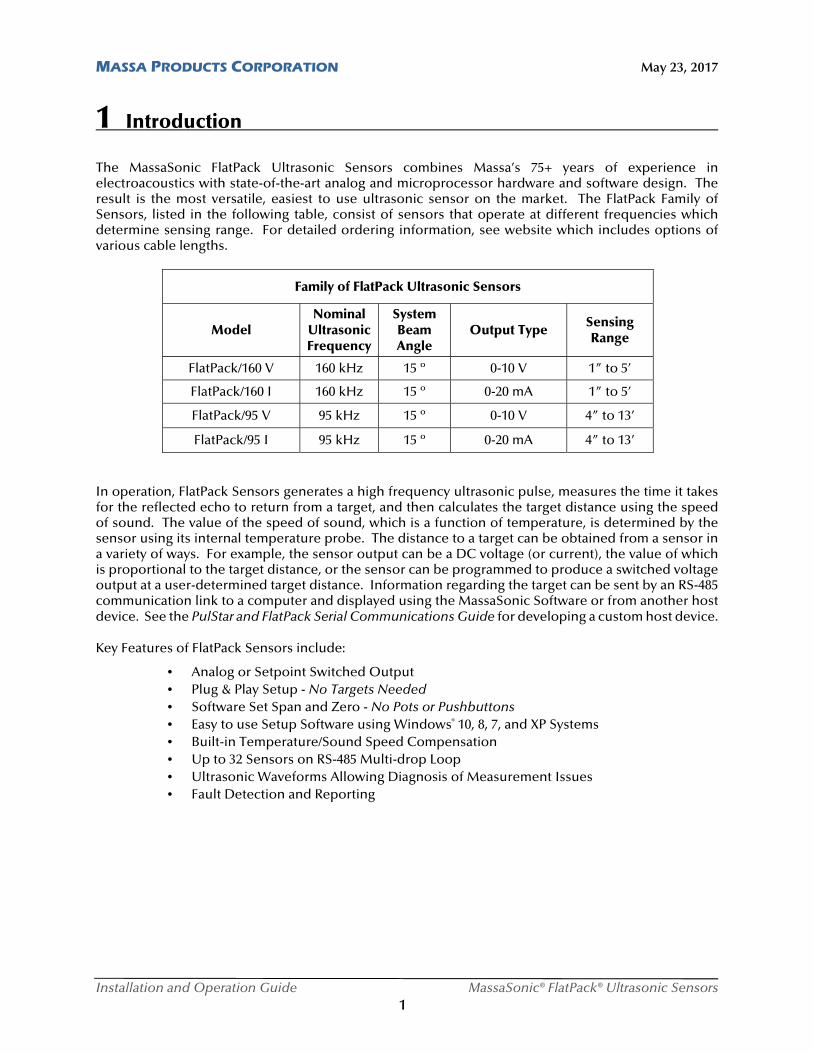
1 Introduction The MassaSonic FlatPack Ultrasonic Sensors combines Massa’s 75+ years of experience in electroacoustics with state-of-the-art analog and microprocessor hardware and software design. The result is the most versatile, easiest to use ultrasonic sensor on the market. The FlatPack Family of Sensors, listed in the following table, consist of sensors that operate at different frequencies which determine sensing range. For detailed ordering information, see website which includes options of various cable lengths.
Family of FlatPack Ultrasonic Sensors
Model Nominal
Ultrasonic Frequency
System Beam Angle
Output Type Sensing Range
FlatPack/160 V 160 kHz 15 º 0-10 V 1” to 5’
FlatPack/160 I 160 kHz 15 º 0-20 mA 1” to 5’
FlatPack/95 V 95 kHz 15 º 0-10 V 4” to 13’
FlatPack/95 I 95 kHz 15 º 0-20 mA 4” to 13’
In operation, FlatPack Sensors generates a high frequency ultrasonic pulse, measures the time it takes for the reflected echo to return from a target, and then calculates the target distance using the speed of sound. The value of the speed of sound, which is a function of temperature, is determined by the sensor using its internal temperature probe. The distance to a target can be obtained from a sensor in a variety of ways. For example, the sensor output can be a DC voltage (or current), the value of which is proportional to the target distance, or the sensor can be programmed to produce a switched voltage output at a user-determined target distance. Information regarding the target can be sent by an RS-485 communication link to a computer and displayed using the MassaSonic Software or from another host device. See the PulStar and FlatPack Serial Communications Guide for developing a custom host device.
Key Features of FlatPack Sensors include:
• Analog or Setpoint Switched Output • Plug & Play Setup - No Targets Needed • Software Set Span and Zero - No Pots or Pushbuttons • Easy to use Setup Software using Windows® 10, 8, 7, and XP Systems • Built-in Temperature/Sound Speed Compensation • Up to 32 Sensors on RS-485 Multi-drop Loop • Ultrasonic Waveforms Allowing Diagnosis of Measurement Issues • Fault Detection and Reporting
MASSA PRODUCTS CORPORATION May 23, 2017
Installation and Operation Guide MassaSonic® FlatPack® Ultrasonic Sensors 2
2 Quick Guide on Getting Started
Mounting the FlatPack Sensor
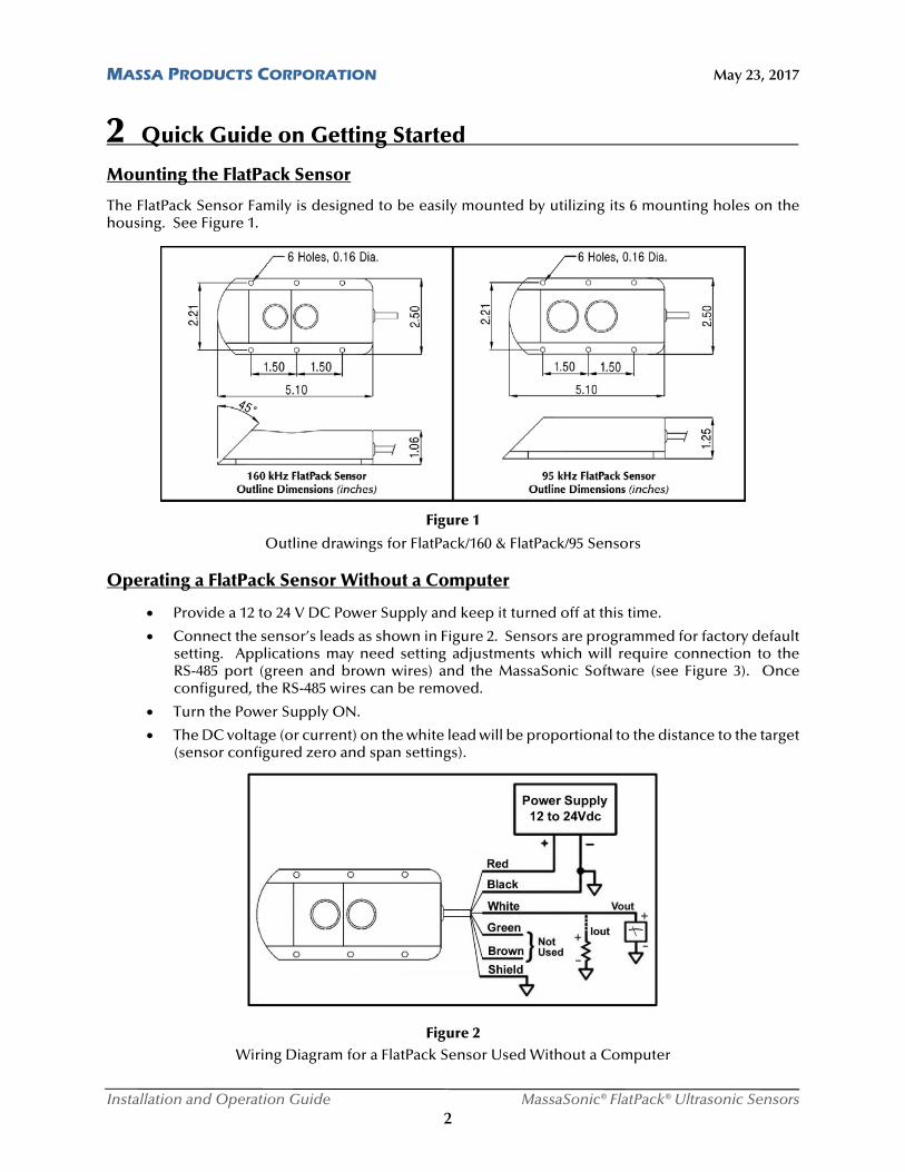
The FlatPack Sensor Family is designed to be easily mounted by utilizing its 6 mounting holes on the housing. See Figure 1.
Figure 1
Outline drawings for FlatPack/160 & FlatPack/95 Sensors Operating a FlatPack Sensor Without a Computer
Provide a 12 to 24 V DC Power Supply and keep it turned off at this time.
Connect the sensor’s leads as shown in Figure 2. Sensors are programmed for factory default setting. Applications may need setting adjustments which will require connection to the RS-485 port (green and brown wires) and the MassaSonic Software (see Figure 3). Once configured, the RS-485 wires can be removed.
Turn the Power Supply ON.
The DC voltage (or current) on the white lead will be proportional to the distance to the target (sensor configured zero and span settings).
Figure 2 Wiring Diagram for a FlatPack Sensor Used Without a Computer
MASSA PRODUCTS CORPORATION May 23, 2017
Installation and Operation Guide MassaSonic® FlatPack® Ultrasonic Sensors 3
2 Quick Guide on Getting Started (continued)
Operating a FlatPack Sensor Connected to a Computer
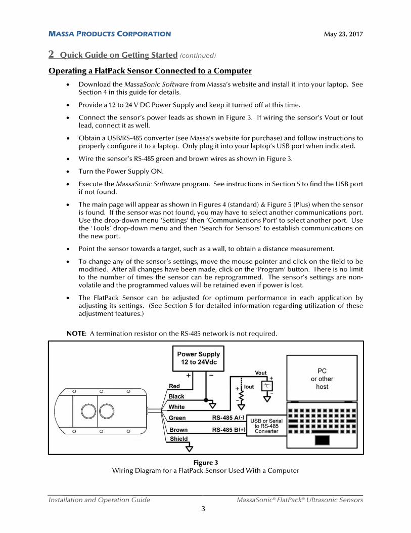
Download the MassaSonic Software from Massa’s website and install it into your laptop. See Section 4 in this guide for details.
Provide a 12 to 24 V DC Power Supply and keep it turned off at this time.
Connect the sensor’s power leads as shown in Figure 3. If wiring the sensor’s Vout or Iout lead, connect it as well.
Obtain a USB/RS-485 converter (see Massa’s website for purchase) and follow instructions to properly configure it to a laptop. Only plug it into your laptop’s USB port when indicated.
Wire the sensor’s RS-485 green and brown wires as shown in Figure 3.
Turn the Power Supply ON.
Execute the MassaSonic Software program. See instructions in Section 5 to find the USB port if not found.
The main page will appear as shown in Figures 4 (standard) & Figure 5 (Plus) when the sensor is found. If the sensor was not found, you may have to select another communications port. Use the drop-down menu ‘Settings’ then ‘Communications Port’ to select another port. Use the ‘Tools’ drop-down menu and then ‘Search for Sensors’ to establish communications on the new port.
Point the sensor towards a target, such as a wall, to obtain a distance measurement.
To change any of the sensor’s settings, move the mouse pointer and click on the field to be modified. After all changes have been made, click on the ‘Program’ button. There is no limit to the number of times the sensor can be reprogrammed. The sensor’s settings are non-volatile and the programmed values will be retained even if power is lost.
The FlatPack Sensor can be adjusted for optimum performance in each application by adjusting its settings. (See Section 5 for detailed information regarding utilization of these adjustment features.)
NOTE: A termination resistor on the RS-485 network is not required.
Figure 3 Wiring Diagram for a FlatPack Sensor Used With a Computer
MASSA PRODUCTS CORPORATION May 23, 2017
Installation and Operation Guide MassaSonic® FlatPack® Ultrasonic Sensors 4
2 Quick Guide on Getting Started (continued) `
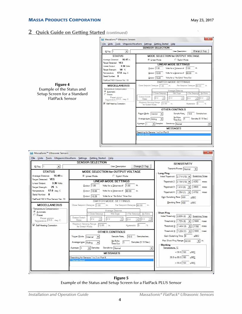
Figure 4 Example of the Status and
Setup Screen for a Standard FlatPack Sensor
Figure 5 Example of the Status and Setup Screen for a FlatPack PLUS Sensor
MASSA PRODUCTS CORPORATION May 23, 2017
Installation and Operation Guide MassaSonic® FlatPack® Ultrasonic Sensors 5
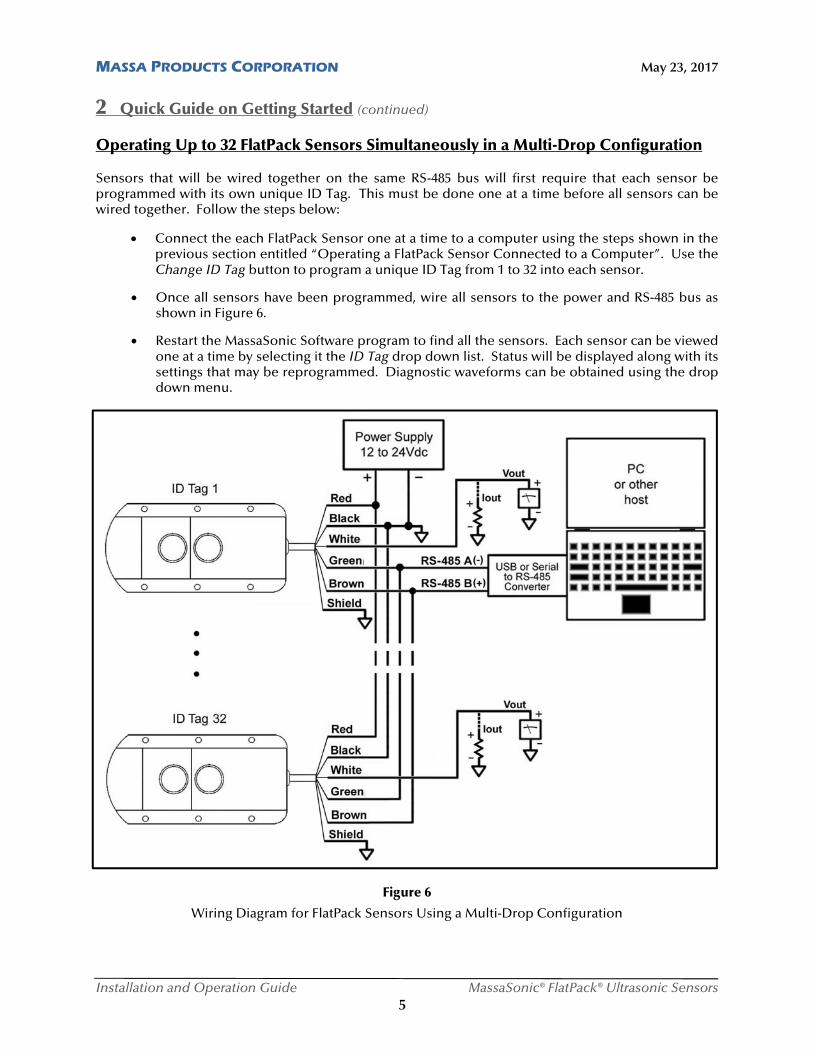
2 Quick Guide on Getting Started (continued) Operating Up to 32 FlatPack Sensors Simultaneously in a Multi-Drop Configuration
Sensors that will be wired together on the same RS-485 bus will first require that each sensor be programmed with its own unique ID Tag. This must be done one at a time before all sensors can be wired together. Follow the steps below:
Connect the each FlatPack Sensor one at a time to a computer using the steps shown in the previous section entitled “Operating a FlatPack Sensor Connected to a Computer”. Use the Change ID Tag button to program a unique ID Tag from 1 to 32 into each sensor.
Once all sensors have been programmed, wire all sensors to the power and RS-485 bus as shown in Figure 6.
Restart the MassaSonic Software program to find all the sensors. Each sensor can be viewed one at a time by selecting it the ID Tag drop down list. Status will be displayed along with its settings that may be reprogrammed. Diagnostic waveforms can be obtained using the drop down menu.
Figure 6
Wiring Diagram for FlatPack Sensors Using a Multi-Drop Configuration
MASSA PRODUCTS CORPORATION May 23, 2017
Installation and Operation Guide MassaSonic® FlatPack® Ultrasonic Sensors 6
3 Product Description
This section contains a general overview of the FlatPack Family of Ultrasonic Sensors. For detailed information on any specific sensor model, refer to the datasheet located on the Massa website (www.massa.com).
DC Power Requirements
FlatPack Sensors are powered from 12 to 24 V DC sources, either batteries or power supplies, that are capable of supplying currents of approximately 30 mA (Vout models) and up to 50 mA (Iout models). The red and black wires of a sensor must be connected to the DC power, as shown above in Figures 2, 3, and 6.
Voltage Output Models and Current Output Models
The sensor’s white lead produces 0-10 V DC (Vout) for the voltage output models, and 4 to 20 mA (or 0 to 20 mA) DC (Iout) for the current output models. The value of the voltage or current output relates to the measured distance to the target. Each type of sensor has two modes of operation. In the Proportional Voltage or Current Output Modes, Vout or Iout are directly proportional to the Target Distance. In the Switched Setpoint Voltage or Current Output Modes, Vout or Iout switches between 0 and 10 V or 0 and 20 mA based on the Target Distance falling within specific distance zones that are programmed into the sensor as Setpoints. More detailed information regarding the use of these operational modes is contained in Section 5.
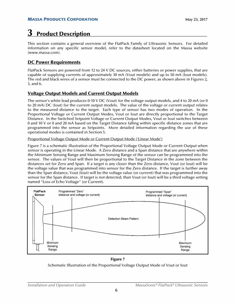
Proportional Voltage Output Mode or Current Output Mode (‘Linear Mode’)
Figure 7 is a schematic illustration of the Proportional Voltage Output Mode or Current Output when sensor is operating in the Linear Mode. A Zero distance and a Span distance that are anywhere within the Minimum Sensing Range and Maximum Sensing Range of the sensor can be programmed into the sensor. The values of Vout will then be proportional to the Target Distance in the zone between the distances set for Zero and Span. If a target is any closer than the Zero distance, Vout (or Iout) will be the voltage value that was programmed into sensor for the Zero distance. If the target is further away than the Span distance, Vout (Iout) will be the voltage value (or current) that was programmed into the sensor for the Span distance. If target is not detected, than Vout (or Iout) will be a third voltage setting named “Loss of Echo Voltage” (or Current).
Figure 7
Schematic Illustration of the Proportional Voltage Output Mode of Vout or Iout
MASSA PRODUCTS CORPORATION May 23, 2017
Installation and Operation Guide MassaSonic® FlatPack® Ultrasonic Sensors 7
3 Product Description (continued)
In the ‘Linear Mode’, the user can set the values for the following programming options using the Status and Setup Screen shown in Figure 4.
1) Set any Output Voltage value from 0 V DC to 10.25 V DC (or current from 0 mA to 20.5 mA) for the Zero Distance
2) Set any Output Voltage value from 0 V DC to 10.25 V DC (or current from 0 mA to 20.5 mA) for the Span Distance
3) Set any Output Voltage value from 0 V DC to 10.25 V DC (or current from 0 mA to 20.5 mA) for the No Echo Time Out to indicate that the target is “lost”, which occurs after the preset number of samples that were programmed into the ‘No Echo Time Out’ in the ‘Sampling Settings’.
With this flexibility, positive or negative slopes can be established, along with any start and end voltage value (or current). Targets within the detection zone, established by the Zero and Span distances, will produce an output voltage (or current) that is proportional to the Target Distance between the Zero Output Voltage and the Span Output Voltage. Targets detected beyond the endpoints of the selected distance zone will produce output voltage (or current) equal to the nearer endpoint. Targets detected closer than the minimum specified Sensing Range will produce a voltage (or current) equal to the Outpoint Voltage programmed for the Zero distance. Targets detected at distances greater than the programmed Span distance will produce a voltage (or current) equal to the Output Voltage (or current) programmed for the Span distance. If no target is detected, a voltage (or current) will be the Output Voltage (or current) programmed for ‘No Echo Time Out’.
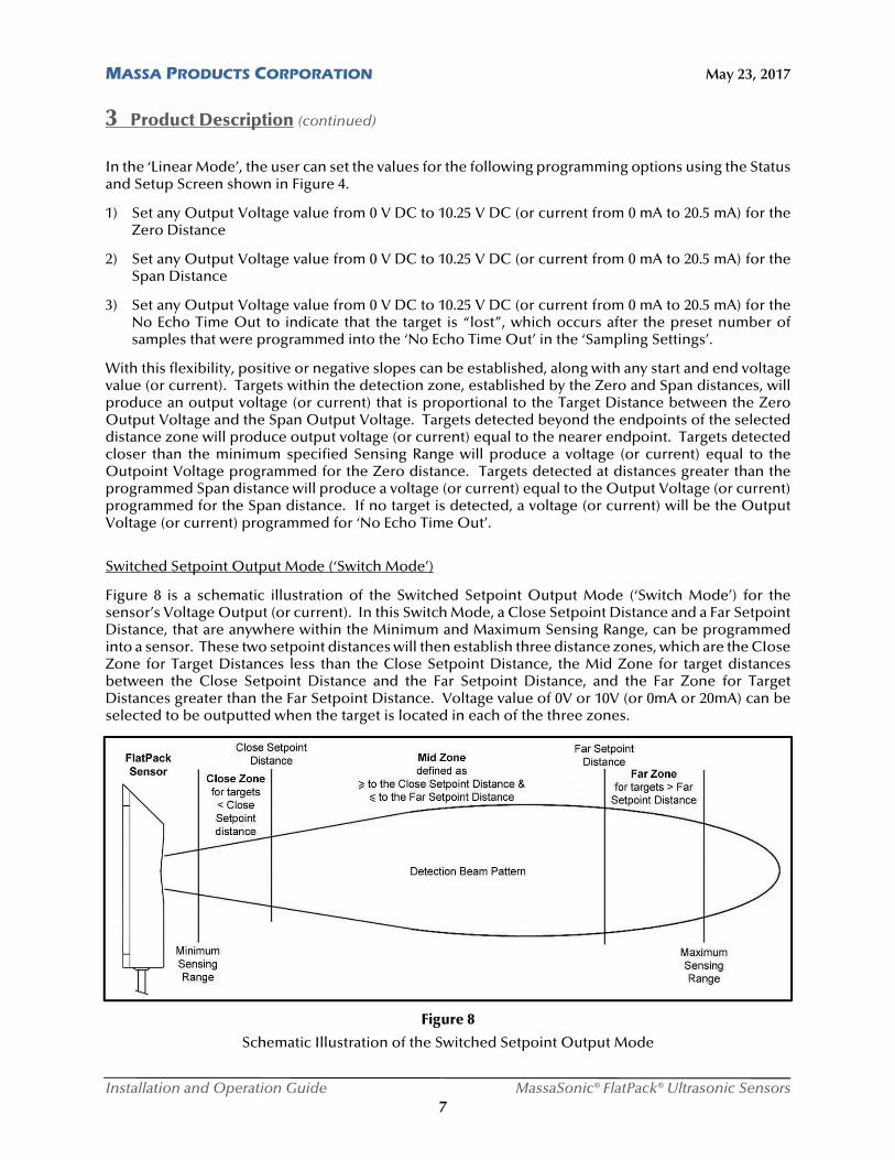
Switched Setpoint Output Mode (‘Switch Mode’)
Figure 8 is a schematic illustration of the Switched Setpoint Output Mode (‘Switch Mode’) for the sensor’s Voltage Output (or current). In this Switch Mode, a Close Setpoint Distance and a Far Setpoint Distance, that are anywhere within the Minimum and Maximum Sensing Range, can be programmed into a sensor. These two setpoint distances will then establish three distance zones, which are the CIose Zone for Target Distances less than the Close Setpoint Distance, the Mid Zone for target distances between the Close Setpoint Distance and the Far Setpoint Distance, and the Far Zone for Target Distances greater than the Far Setpoint Distance. Voltage value of 0V or 10V (or 0mA or 20mA) can be selected to be outputted when the target is located in each of the three zones.
Figure 8
Schematic Illustration of the Switched Setpoint Output Mode
MASSA PRODUCTS CORPORATION May 23, 2017
Installation and Operation Guide MassaSonic® FlatPack® Ultrasonic Sensors 8
3 Product Description (continued)
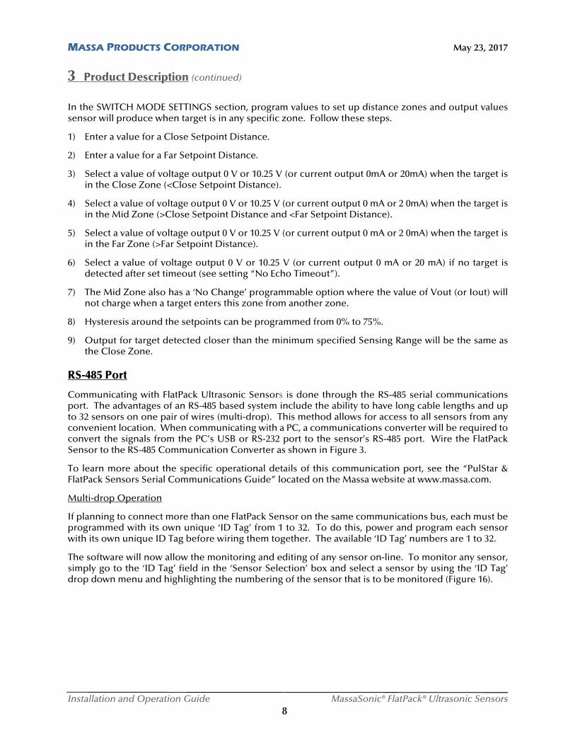
In the SWITCH MODE SETTINGS section, program values to set up distance zones and output values sensor will produce when target is in any specific zone. Follow these steps.
1) Enter a value for a Close Setpoint Distance.
2) Enter a value for a Far Setpoint Distance.
3) Select a value of voltage output 0 V or 10.25 V (or current output 0mA or 20mA) when the target is in the Close Zone (<Close Setpoint Distance).
4) Select a value of voltage output 0 V or 10.25 V (or current output 0 mA or 2 0mA) when the target is in the Mid Zone (>Close Setpoint Distance and <Far Setpoint Distance).
5) Select a value of voltage output 0 V or 10.25 V (or current output 0 mA or 2 0mA) when the target is in the Far Zone (>Far Setpoint Distance).
6) Select a value of voltage output 0 V or 10.25 V (or current output 0 mA or 20 mA) if no target is detected after set timeout (see setting “No Echo Timeout”).
7) The Mid Zone also has a ‘No Change’ programmable option where the value of Vout (or Iout) will not charge when a target enters this zone from another zone.
8) Hysteresis around the setpoints can be programmed from 0% to 75%.
9) Output for target detected closer than the minimum specified Sensing Range will be the same as the Close Zone.
RS-485 Port
Communicating with FlatPack Ultrasonic Sensors is done through the RS-485 serial communications port. The advantages of an RS-485 based system include the ability to have long cable lengths and up to 32 sensors on one pair of wires (multi-drop). This method allows for access to all sensors from any convenient location. When communicating with a PC, a communications converter will be required to convert the signals from the PC’s USB or RS-232 port to the sensor’s RS-485 port. Wire the FlatPack Sensor to the RS-485 Communication Converter as shown in Figure 3.
To learn more about the specific operational details of this communication port, see the “PulStar & FlatPack Sensors Serial Communications Guide” located on the Massa website at www.massa.com.
Multi-drop Operation
If planning to connect more than one FlatPack Sensor on the same communications bus, each must be programmed with its own unique ‘ID Tag’ from 1 to 32. To do this, power and program each sensor with its own unique ID Tag before wiring them together. The available ‘ID Tag’ numbers are 1 to 32.
The software will now allow the monitoring and editing of any sensor on-line. To monitor any sensor, simply go to the ‘ID Tag’ field in the ‘Sensor Selection’ box and select a sensor by using the ‘ID Tag’ drop down menu and highlighting the numbering of the sensor that is to be monitored (Figure 16).
MASSA PRODUCTS CORPORATION May 23, 2017
Installation and Operation Guide MassaSonic® FlatPack® Ultrasonic Sensors 9
4 Installing MassaSonic™ Software _
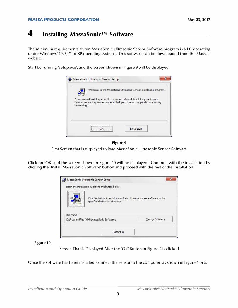
The minimum requirements to run MassaSonic Ultrasonic Sensor Software program is a PC operating under Windows® 10, 8, 7, or XP operating systems. This software can be downloaded from the Massa’s website.
Start by running ‘setup.exe’, and the screen shown in Figure 9 will be displayed.
Figure 9
First Screen that is displayed to load MassaSonic Ultrasonic Sensor Software
Click on ‘OK’ and the screen shown in Figure 10 will be displayed. Continue with the installation by clicking the ‘Install MassaSonic Software’ button and proceed with the rest of the installation.
Figure 10
Screen That Is Displayed After the ‘OK’ Button in Figure 9 is clicked Once the software has been installed, connect the sensor to the computer, as shown in Figure 4 or 5.
MASSA PRODUCTS CORPORATION May 23, 2017
Installation and Operation Guide MassaSonic® FlatPack® Ultrasonic Sensors 10
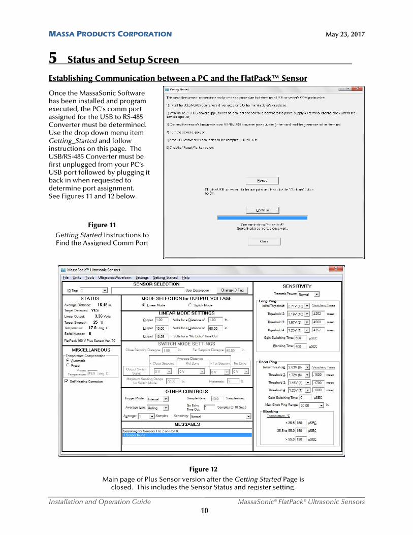
5 Status and Setup Screen Establishing Communication between a PC and the FlatPack™ Sensor
Once the MassaSonic Software has been installed and program executed, the PC’s comm port assigned for the USB to RS-485 Converter must be determined. Use the drop down menu item Getting_Started and follow instructions on this page. The USB/RS-485 Converter must be first unplugged from your PC’s USB port followed by plugging it back in when requested to determine port assignment. See Figures 11 and 12 below.
Figure 11 Getting Started Instructions to Find the Assigned Comm Port
Figure 12 Main page of Plus Sensor version after the Getting Started Page is
closed. This includes the Sensor Status and register setting.

MASSA PRODUCTS CORPORATION May 23, 2017
Installation and Operation Guide MassaSonic® FlatPack® Ultrasonic Sensors 11
5 Status and Setup Screen (continued) Status Box of the Status and Setup Screen
The ‘Status’ box displays the various parameters for the particular FlatPack Sensor whose ‘ID Tag’ is displayed in the ‘Sensor Selection’ box of the Status and Setup Screen. This field is updated approximately every ¼ of a second. An example is shown in Figure 13.
Figure 13
Example of the Status Box of the Status and Setup Screen
‘Average Distance’: Measured average Target Distance to target. Number of samples in the average and the average type is programmable by using the ‘Sampling Settings’ box.
‘Target Detected’: Indicates that a target is detected. If the sensor is in the ‘Switch Mode’ and if the target is beyond the programmed ‘Maximum Sensing Range’ for ‘Switch Mode’, the ‘Target Detected’ indication will be ‘NO’.
‘Linear Output’ or ‘Switch Output’: Indicates the value of Vout, which is proportional to the Target Distance if the sensor’s voltage output (or current) is programmed in the ‘Linear Mode. If the sensor’s voltage output (or current) is programmed for ‘Switch Mode’ operation, it will indicate either 0 V or 10 V (0 mA or 20 mA for Iout model sensors).
‘Target Strength’: Measure of the relative strength of the received ultrasonic echo signal and can be used to align either the target or the sensor to produce the optimum echo.
‘Temperature’: Temperature reading of the internal probe in the sensor when ‘Automatic’ is selected in the ‘Temperature Compensation’ box. If ‘Preset’ is selected in the ‘Temperature Compensation’ box, then the preset temperature that was entered will be displayed.
‘Serial Number’: The serial number of the sensor assigned at the factory.
The last line in the ‘Status’ box is the sensor description including its firmware version number.
MASSA PRODUCTS CORPORATION May 23, 2017
Installation and Operation Guide MassaSonic® FlatPack® Ultrasonic Sensors 12
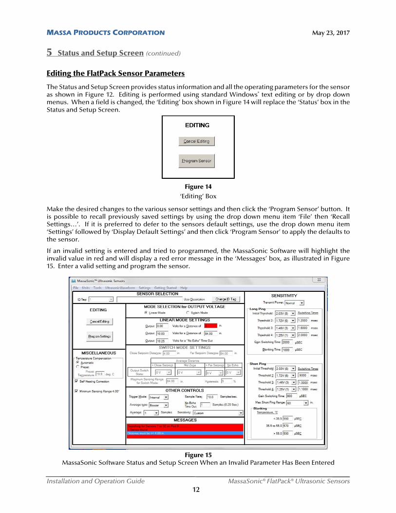
5 Status and Setup Screen (continued) Editing the FlatPack Sensor Parameters
The Status and Setup Screen provides status information and all the operating parameters for the sensor as shown in Figure 12. Editing is performed using standard Windows® text editing or by drop down menus. When a field is changed, the ‘Editing’ box shown in Figure 14 will replace the ‘Status’ box in the Status and Setup Screen.
Figure 14 ‘Editing’ Box
Make the desired changes to the various sensor settings and then click the ‘Program Sensor’ button. It is possible to recall previously saved settings by using the drop down menu item ‘File’ then ‘Recall Settings…’. If it is preferred to defer to the sensors default settings, use the drop down menu item ‘Settings’ followed by ‘Display Default Settings’ and then click ‘Program Sensor’ to apply the defaults to the sensor.
If an invalid setting is entered and tried to programmed, the MassaSonic Software will highlight the invalid value in red and will display a red error message in the ‘Messages’ box, as illustrated in Figure 15. Enter a valid setting and program the sensor.
Figure 15 MassaSonic Software Status and Setup Screen When an Invalid Parameter Has Been Entered
MASSA PRODUCTS CORPORATION May 23, 2017
Installation and Operation Guide MassaSonic® FlatPack® Ultrasonic Sensors 13
5 Status and Setup Screen (continued)
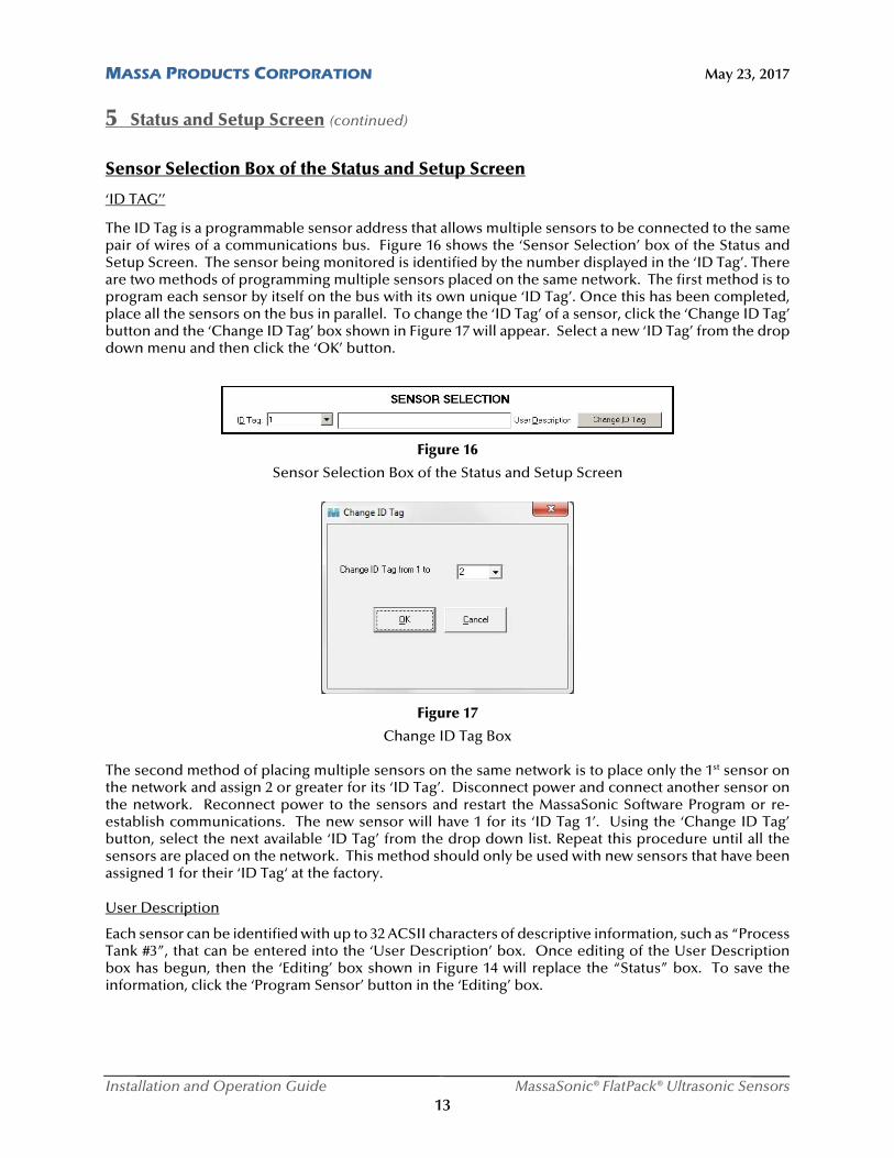
Sensor Selection Box of the Status and Setup Screen
‘ID TAG’’
The ID Tag is a programmable sensor address that allows multiple sensors to be connected to the same pair of wires of a communications bus. Figure 16 shows the ‘Sensor Selection’ box of the Status and Setup Screen. The sensor being monitored is identified by the number displayed in the ‘ID Tag’. There are two methods of programming multiple sensors placed on the same network. The first method is to program each sensor by itself on the bus with its own unique ‘ID Tag’. Once this has been completed, place all the sensors on the bus in parallel. To change the ‘ID Tag’ of a sensor, click the ‘Change ID Tag’ button and the ‘Change ID Tag’ box shown in Figure 17 will appear. Select a new ‘ID Tag’ from the drop down menu and then click the ‘OK’ button.
Figure 16
Sensor Selection Box of the Status and Setup Screen
Figure 17
Change ID Tag Box The second method of placing multiple sensors on the same network is to place only the 1st sensor on the network and assign 2 or greater for its ‘ID Tag’. Disconnect power and connect another sensor on the network. Reconnect power to the sensors and restart the MassaSonic Software Program or re-establish communications. The new sensor will have 1 for its ‘ID Tag 1’. Using the ‘Change ID Tag’ button, select the next available ‘ID Tag’ from the drop down list. Repeat this procedure until all the sensors are placed on the network. This method should only be used with new sensors that have been assigned 1 for their ‘ID Tag‘ at the factory.
User Description
Each sensor can be identified with up to 32 ACSII characters of descriptive information, such as “Process Tank #3”, that can be entered into the ‘User Description’ box. Once editing of the User Description box has begun, then the ‘Editing’ box shown in Figure 14 will replace the “Status” box. To save the information, click the ‘Program Sensor’ button in the ‘Editing’ box.
MASSA PRODUCTS CORPORATION May 23, 2017
Installation and Operation Guide MassaSonic® FlatPack® Ultrasonic Sensors 14
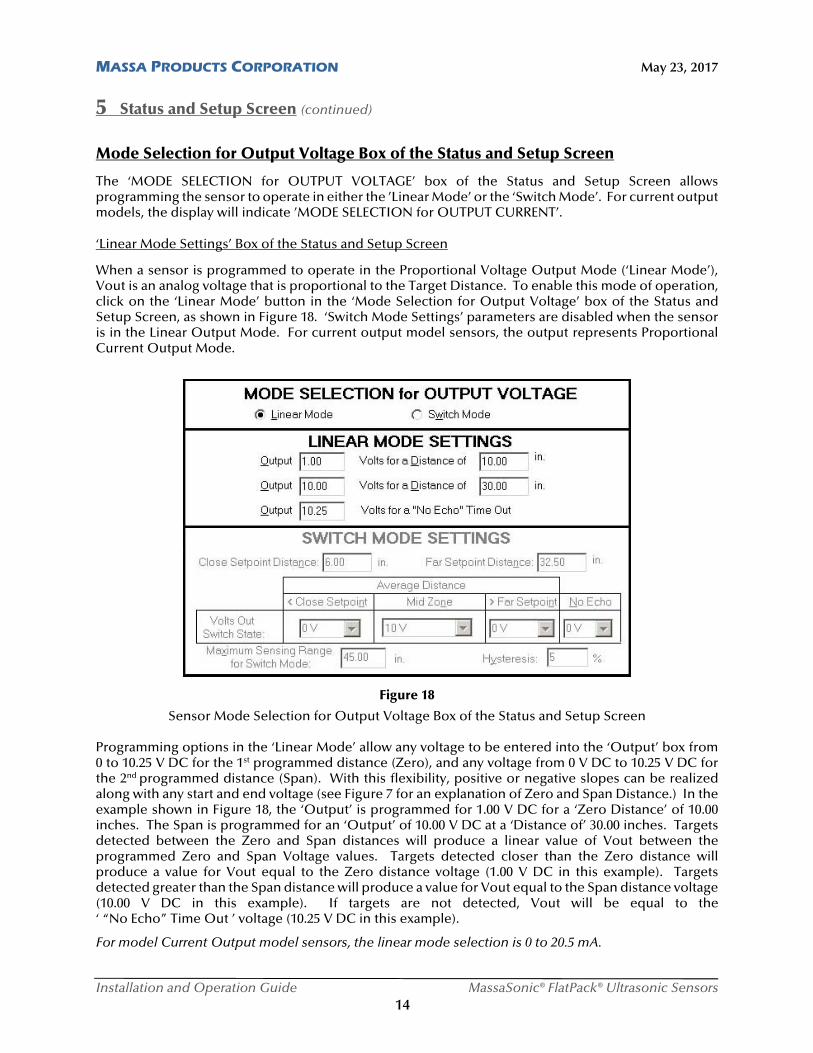
5 Status and Setup Screen (continued) Mode Selection for Output Voltage Box of the Status and Setup Screen
The ‘MODE SELECTION for OUTPUT VOLTAGE’ box of the Status and Setup Screen allows programming the sensor to operate in either the ’Linear Mode’ or the ‘Switch Mode’. For current output models, the display will indicate ’MODE SELECTION for OUTPUT CURRENT’.
‘Linear Mode Settings’ Box of the Status and Setup Screen
When a sensor is programmed to operate in the Proportional Voltage Output Mode (‘Linear Mode’), Vout is an analog voltage that is proportional to the Target Distance. To enable this mode of operation, click on the ‘Linear Mode’ button in the ‘Mode Selection for Output Voltage’ box of the Status and Setup Screen, as shown in Figure 18. ‘Switch Mode Settings’ parameters are disabled when the sensor is in the Linear Output Mode. For current output model sensors, the output represents Proportional Current Output Mode.
Figure 18
Sensor Mode Selection for Output Voltage Box of the Status and Setup Screen Programming options in the ‘Linear Mode’ allow any voltage to be entered into the ‘Output’ box from 0 to 10.25 V DC for the 1st programmed distance (Zero), and any voltage from 0 V DC to 10.25 V DC for the 2nd programmed distance (Span). With this flexibility, positive or negative slopes can be realized along with any start and end voltage (see Figure 7 for an explanation of Zero and Span Distance.) In the example shown in Figure 18, the ‘Output’ is programmed for 1.00 V DC for a ‘Zero Distance’ of 10.00 inches. The Span is programmed for an ‘Output’ of 10.00 V DC at a ‘Distance of’ 30.00 inches. Targets detected between the Zero and Span distances will produce a linear value of Vout between the programmed Zero and Span Voltage values. Targets detected closer than the Zero distance will produce a value for Vout equal to the Zero distance voltage (1.00 V DC in this example). Targets detected greater than the Span distance will produce a value for Vout equal to the Span distance voltage (10.00 V DC in this example). If targets are not detected, Vout will be equal to the ‘ “No Echo” Time Out ’ voltage (10.25 V DC in this example).
For model Current Output model sensors, the linear mode selection is 0 to 20.5 mA.
MASSA PRODUCTS CORPORATION May 23, 2017
Installation and Operation Guide MassaSonic® FlatPack® Ultrasonic Sensors 15
5 Status and Setup Screen (continued)
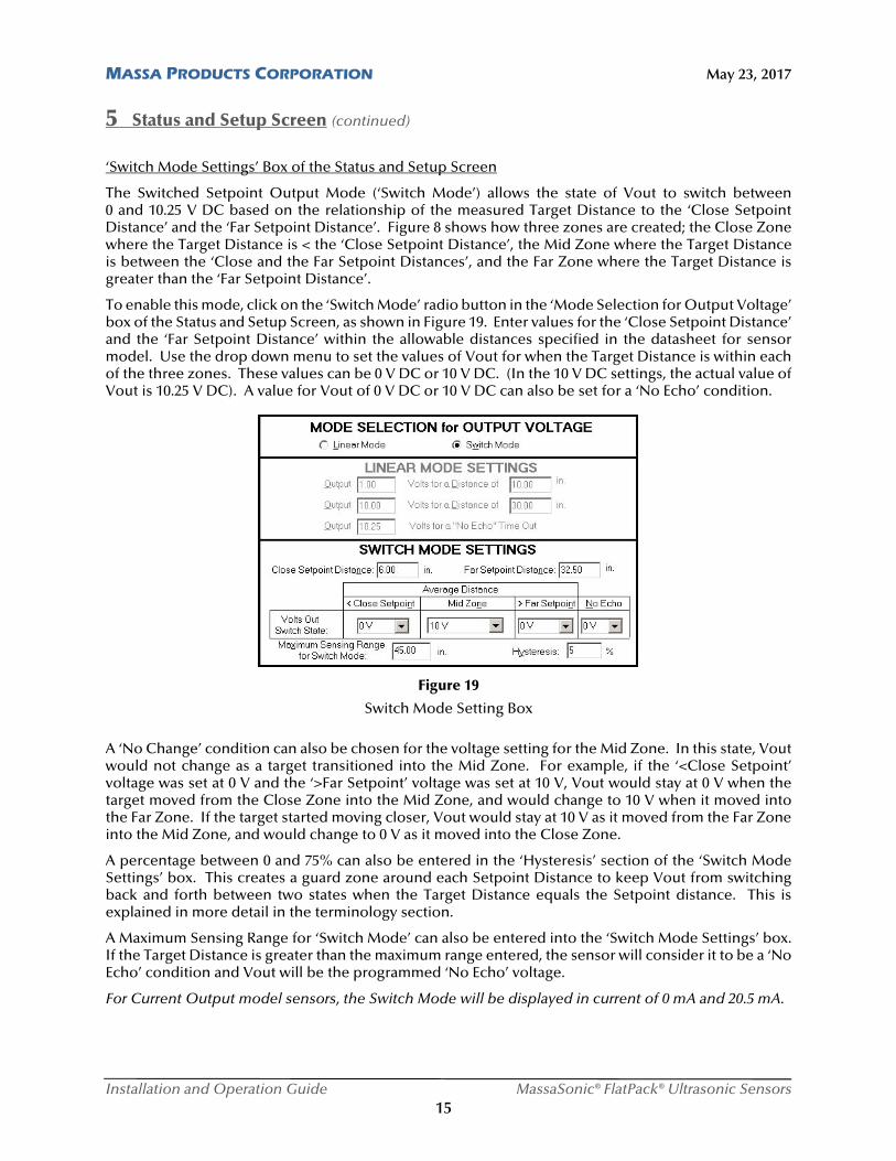
‘Switch Mode Settings’ Box of the Status and Setup Screen
The Switched Setpoint Output Mode (‘Switch Mode’) allows the state of Vout to switch between 0 and 10.25 V DC based on the relationship of the measured Target Distance to the ‘Close Setpoint Distance’ and the ‘Far Setpoint Distance’. Figure 8 shows how three zones are created; the Close Zone where the Target Distance is < the ‘Close Setpoint Distance’, the Mid Zone where the Target Distance is between the ‘Close and the Far Setpoint Distances’, and the Far Zone where the Target Distance is greater than the ‘Far Setpoint Distance’.
To enable this mode, click on the ‘Switch Mode’ radio button in the ‘Mode Selection for Output Voltage’ box of the Status and Setup Screen, as shown in Figure 19. Enter values for the ‘Close Setpoint Distance’ and the ‘Far Setpoint Distance’ within the allowable distances specified in the datasheet for sensor model. Use the drop down menu to set the values of Vout for when the Target Distance is within each of the three zones. These values can be 0 V DC or 10 V DC. (In the 10 V DC settings, the actual value of Vout is 10.25 V DC). A value for Vout of 0 V DC or 10 V DC can also be set for a ‘No Echo’ condition.
Figure 19
Switch Mode Setting Box
A ‘No Change’ condition can also be chosen for the voltage setting for the Mid Zone. In this state, Vout would not change as a target transitioned into the Mid Zone. For example, if the ‘<Close Setpoint’ voltage was set at 0 V and the ‘>Far Setpoint’ voltage was set at 10 V, Vout would stay at 0 V when the target moved from the Close Zone into the Mid Zone, and would change to 10 V when it moved into the Far Zone. If the target started moving closer, Vout would stay at 10 V as it moved from the Far Zone into the Mid Zone, and would change to 0 V as it moved into the Close Zone.
A percentage between 0 and 75% can also be entered in the ‘Hysteresis’ section of the ‘Switch Mode Settings’ box. This creates a guard zone around each Setpoint Distance to keep Vout from switching back and forth between two states when the Target Distance equals the Setpoint distance. This is explained in more detail in the terminology section.
A Maximum Sensing Range for ‘Switch Mode’ can also be entered into the ‘Switch Mode Settings’ box. If the Target Distance is greater than the maximum range entered, the sensor will consider it to be a ‘No Echo’ condition and Vout will be the programmed ‘No Echo’ voltage.
For Current Output model sensors, the Switch Mode will be displayed in current of 0 mA and 20.5 mA.
MASSA PRODUCTS CORPORATION May 23, 2017
Installation and Operation Guide MassaSonic® FlatPack® Ultrasonic Sensors 16
5 Status and Setup Screen (continued)
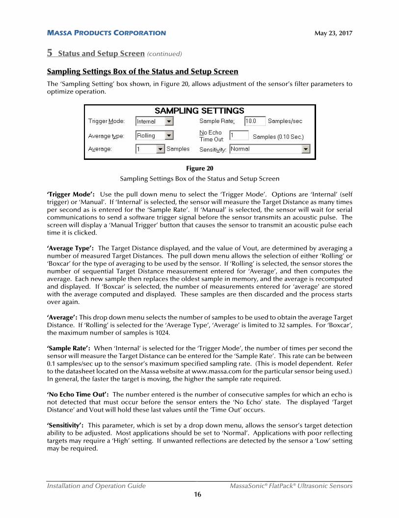
Sampling Settings Box of the Status and Setup Screen
The ‘Sampling Setting’ box shown, in Figure 20, allows adjustment of the sensor’s filter parameters to optimize operation.
Figure 20
Sampling Settings Box of the Status and Setup Screen ‘Trigger Mode’: Use the pull down menu to select the ‘Trigger Mode’. Options are ‘Internal’ (self trigger) or ‘Manual’. If ‘Internal’ is selected, the sensor will measure the Target Distance as many times per second as is entered for the ‘Sample Rate’. If ‘Manual’ is selected, the sensor will wait for serial communications to send a software trigger signal before the sensor transmits an acoustic pulse. The screen will display a ‘Manual Trigger’ button that causes the sensor to transmit an acoustic pulse each time it is clicked. ‘Average Type’: The Target Distance displayed, and the value of Vout, are determined by averaging a number of measured Target Distances. The pull down menu allows the selection of either ‘Rolling’ or ‘Boxcar’ for the type of averaging to be used by the sensor. If ‘Rolling’ is selected, the sensor stores the number of sequential Target Distance measurement entered for ‘Average’, and then computes the average. Each new sample then replaces the oldest sample in memory, and the average is recomputed and displayed. If ‘Boxcar’ is selected, the number of measurements entered for ‘average’ are stored with the average computed and displayed. These samples are then discarded and the process starts over again. ‘Average’: This drop down menu selects the number of samples to be used to obtain the average Target Distance. If ‘Rolling’ is selected for the ‘Average Type’, ‘Average’ is limited to 32 samples. For ‘Boxcar’, the maximum number of samples is 1024. ‘Sample Rate’: When ‘Internal’ is selected for the ‘Trigger Mode’, the number of times per second the sensor will measure the Target Distance can be entered for the ‘Sample Rate’. This rate can be between 0.1 samples/sec up to the sensor’s maximum specified sampling rate. (This is model dependent. Refer to the datasheet located on the Massa website at www.massa.com for the particular sensor being used.) In general, the faster the target is moving, the higher the sample rate required. ‘No Echo Time Out’: The number entered is the number of consecutive samples for which an echo is not detected that must occur before the sensor enters the ‘No Echo’ state. The displayed ‘Target Distance’ and Vout will hold these last values until the ‘Time Out’ occurs. ‘Sensitivity’: This parameter, which is set by a drop down menu, allows the sensor’s target detection ability to be adjusted. Most applications should be set to ‘Normal’. Applications with poor reflecting targets may require a ‘High’ setting. If unwanted reflections are detected by the sensor a ‘Low’ setting may be required.
MASSA PRODUCTS CORPORATION May 23, 2017
Installation and Operation Guide MassaSonic® FlatPack® Ultrasonic Sensors 17
( ) 13,044 1273
Tc T
5 Status and Setup Screen (continued)
Miscellaneous Box of the Status and Setup Screen
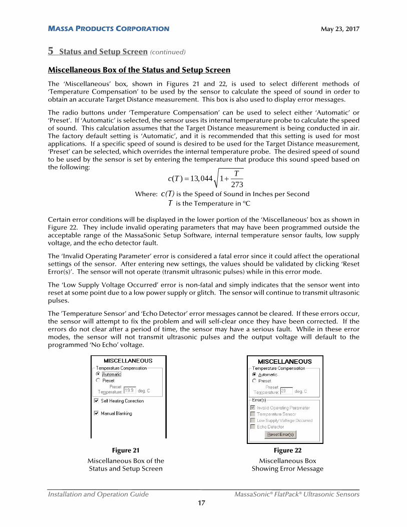
The ‘Miscellaneous’ box, shown in Figures 21 and 22, is used to select different methods of ‘Temperature Compensation’ to be used by the sensor to calculate the speed of sound in order to obtain an accurate Target Distance measurement. This box is also used to display error messages.
The radio buttons under ‘Temperature Compensation’ can be used to select either ‘Automatic’ or ‘Preset’. If ‘Automatic’ is selected, the sensor uses its internal temperature probe to calculate the speed of sound. This calculation assumes that the Target Distance measurement is being conducted in air. The factory default setting is ‘Automatic’, and it is recommended that this setting is used for most applications. If a specific speed of sound is desired to be used for the Target Distance measurement, ‘Preset’ can be selected, which overrides the internal temperature probe. The desired speed of sound to be used by the sensor is set by entering the temperature that produce this sound speed based on the following:
Where: c(T) is the Speed of Sound in Inches per Second T is the Temperature in ºC
Certain error conditions will be displayed in the lower portion of the ‘Miscellaneous’ box as shown in Figure 22. They include invalid operating parameters that may have been programmed outside the acceptable range of the MassaSonic Setup Software, internal temperature sensor faults, low supply voltage, and the echo detector fault.
The ‘Invalid Operating Parameter’ error is considered a fatal error since it could affect the operational settings of the sensor. After entering new settings, the values should be validated by clicking ‘Reset Error(s)’. The sensor will not operate (transmit ultrasonic pulses) while in this error mode.
The ‘Low Supply Voltage Occurred’ error is non-fatal and simply indicates that the sensor went into reset at some point due to a low power supply or glitch. The sensor will continue to transmit ultrasonic pulses.
The ’Temperature Sensor’ and ‘Echo Detector’ error messages cannot be cleared. If these errors occur, the sensor will attempt to fix the problem and will self-clear once they have been corrected. If the errors do not clear after a period of time, the sensor may have a serious fault. While in these error modes, the sensor will not transmit ultrasonic pulses and the output voltage will default to the programmed ‘No Echo’ voltage.
Figure 21 Figure 22
Miscellaneous Box of the Miscellaneous Box Status and Setup Screen Showing Error Message
MASSA PRODUCTS CORPORATION May 23, 2017
Installation and Operation Guide MassaSonic® FlatPack® Ultrasonic Sensors 18
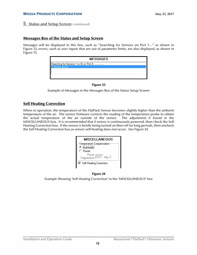
5 Status and Setup Screen (continued) Messages Box of the Status and Setup Screen
Messages will be displayed in this box, such as “Searching for Sensors on Port 1…” as shown in Figure 23, errors, such as user inputs that are out of parameter limits, are also displayed, as shown in Figure 15.
Figure 23
Example of Messages in the Messages Box of the Status Setup Screen
Self Heating Correction
When in operation, the temperature of the FlatPack Sensor becomes slightly higher than the ambient temperature of the air. The sensor firmware corrects the reading of the temperature probe to obtain the actual temperature of the air outside of the sensor. The adjustment if found in the MISCELLANEOUS box. It is recommended that if sensor is continuously powered, then check the Self Heating Correction box. If the sensor is briefly being turned on then off for long periods, then uncheck the Self Heating Correction box as sensor self-heating does not occur. See Figure 24.
Figure 24
Example Showing ‘Self Heating Correction’ in the ‘MISCELLANEOUS’ box
MASSA PRODUCTS CORPORATION May 23, 2017
Installation and Operation Guide MassaSonic® FlatPack® Ultrasonic Sensors 19
5 Status and Setup Screen (continued)
File Tab
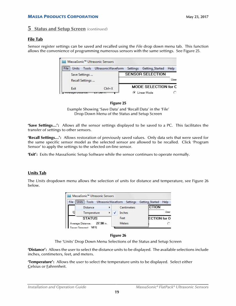
Sensor register settings can be saved and recalled using the File drop down menu tab. This function allows the convenience of programming numerous sensors with the same settings. See Figure 25.
Figure 25
Example Showing ‘Save Data’ and ‘Recall Data’ in the ‘File’ Drop Down Menu of the Status and Setup Screen
‘Save Settings...’: Allows all the sensor settings displayed to be saved to a PC. This facilitates the transfer of settings to other sensors.
‘Recall Settings...’: Allows restoration of previously saved values. Only data sets that were saved for the same specific sensor model as the selected sensor are allowed to be recalled. Click ‘Program Sensor’ to apply the settings to the selected on-line sensor.
‘Exit’: Exits the MassaSonic Setup Software while the sensor continues to operate normally.
Units Tab
The Units dropdown menu allows the selection of units for distance and temperature, see Figure 26 below.
Figure 26
The ‘Units’ Drop Down Menu Selections of the Status and Setup Screen
‘Distance’: Allows the user to select the distance units to be displayed. The available selections include inches, centimeters, feet, and meters.
‘Temperature’: Allows the user to select the temperature units to be displayed. Select either Celsius or Fahrenheit.
MASSA PRODUCTS CORPORATION May 23, 2017
Installation and Operation Guide MassaSonic® FlatPack® Ultrasonic Sensors 20
5 Status and Setup Screen (continued)
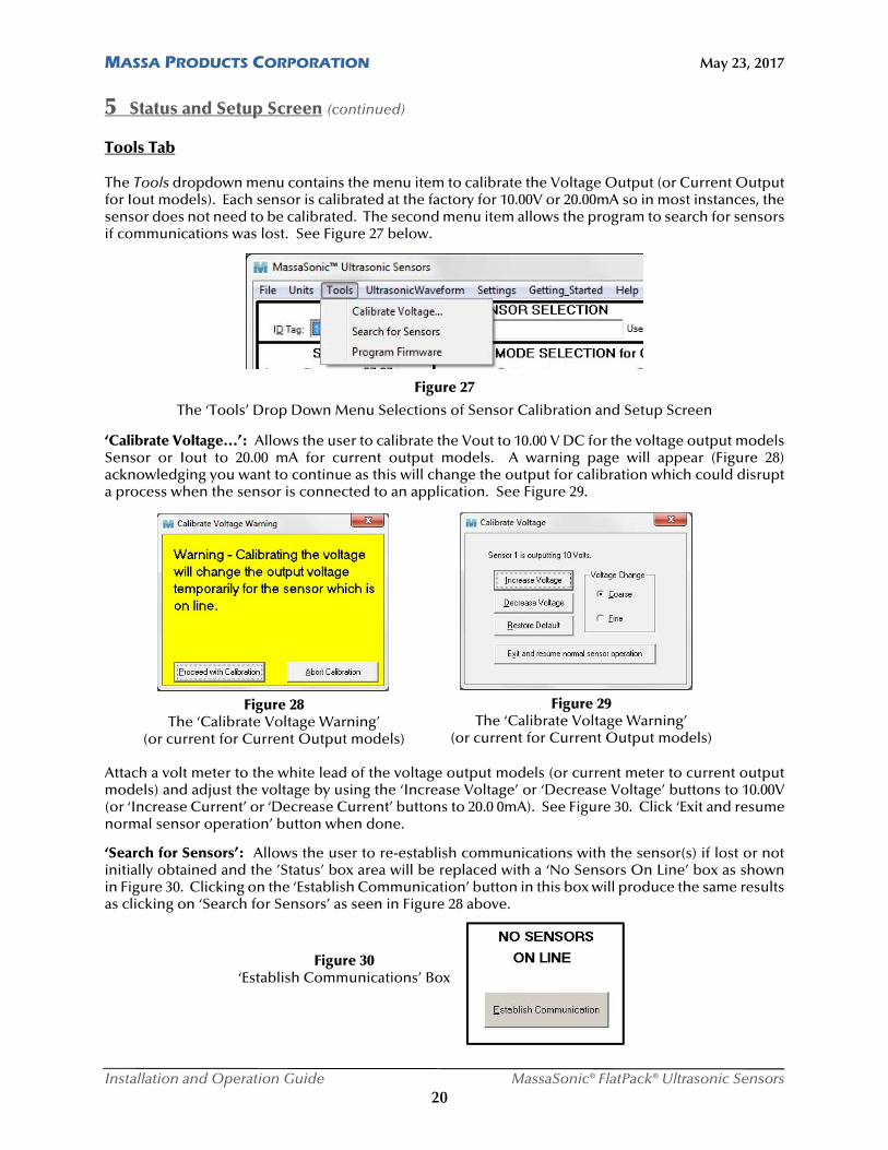
Tools Tab The Tools dropdown menu contains the menu item to calibrate the Voltage Output (or Current Output for Iout models). Each sensor is calibrated at the factory for 10.00V or 20.00mA so in most instances, the sensor does not need to be calibrated. The second menu item allows the program to search for sensors if communications was lost. See Figure 27 below.
Figure 27
The ‘Tools’ Drop Down Menu Selections of Sensor Calibration and Setup Screen
‘Calibrate Voltage…’: Allows the user to calibrate the Vout to 10.00 V DC for the voltage output models Sensor or Iout to 20.00 mA for current output models. A warning page will appear (Figure 28) acknowledging you want to continue as this will change the output for calibration which could disrupt a process when the sensor is connected to an application. See Figure 29.
Attach a volt meter to the white lead of the voltage output models (or current meter to current output models) and adjust the voltage by using the ‘Increase Voltage’ or ‘Decrease Voltage’ buttons to 10.00V (or ‘Increase Current’ or ‘Decrease Current’ buttons to 20.0 0mA). See Figure 30. Click ‘Exit and resume normal sensor operation’ button when done.
‘Search for Sensors’: Allows the user to re-establish communications with the sensor(s) if lost or not initially obtained and the ’Status’ box area will be replaced with a ‘No Sensors On Line’ box as shown in Figure 30. Clicking on the ‘Establish Communication’ button in this box will produce the same results as clicking on ‘Search for Sensors’ as seen in Figure 28 above.
Figure 28 The ‘Calibrate Voltage Warning’
(or current for Current Output models)
Figure 29 The ‘Calibrate Voltage Warning’
(or current for Current Output models)
Figure 30 ‘Establish Communications’ Box
MASSA PRODUCTS CORPORATION May 23, 2017
Installation and Operation Guide MassaSonic® FlatPack® Ultrasonic Sensors 21
5 Status and Setup Screen (continued)
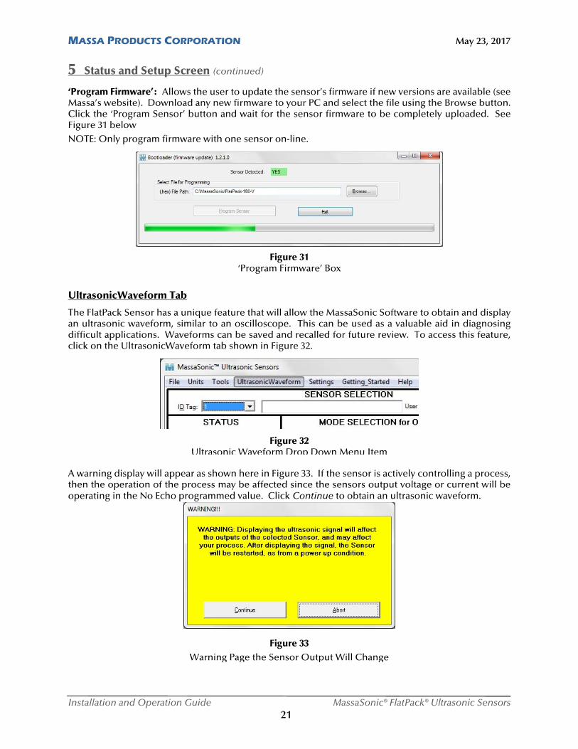
‘Program Firmware’: Allows the user to update the sensor’s firmware if new versions are available (see Massa’s website). Download any new firmware to your PC and select the file using the Browse button. Click the ‘Program Sensor’ button and wait for the sensor firmware to be completely uploaded. See Figure 31 below
NOTE: Only program firmware with one sensor on-line.
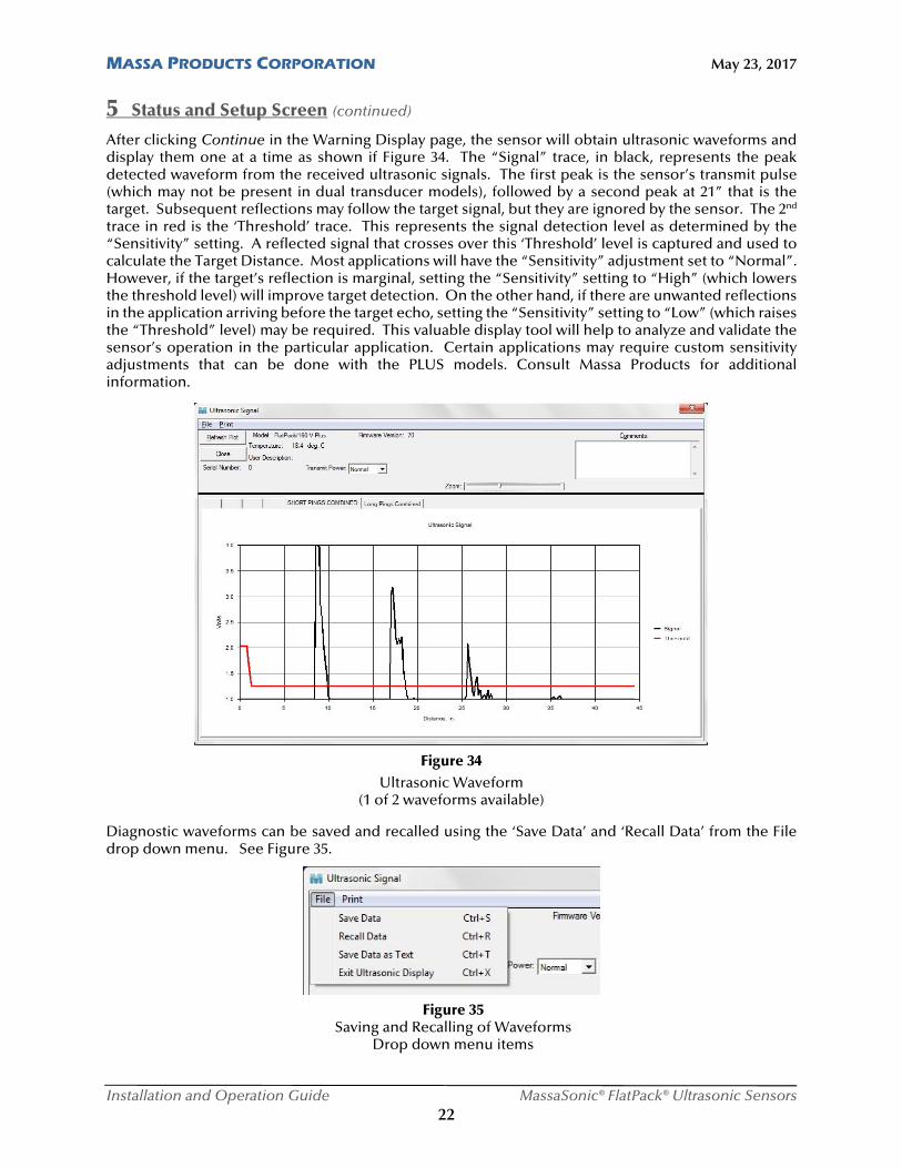
UltrasonicWaveform Tab
The FlatPack Sensor has a unique feature that will allow the MassaSonic Software to obtain and display an ultrasonic waveform, similar to an oscilloscope. This can be used as a valuable aid in diagnosing difficult applications. Waveforms can be saved and recalled for future review. To access this feature, click on the UltrasonicWaveform tab shown in Figure 32.
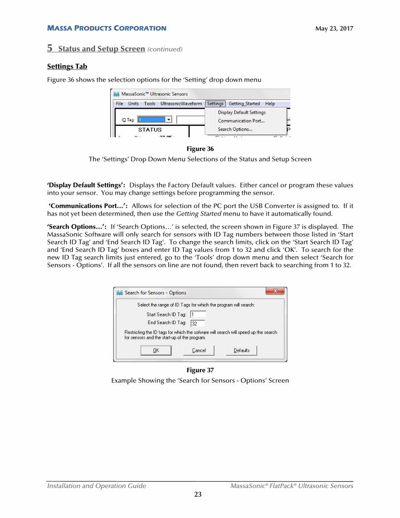
A warning display will appear as shown here in Figure 33. If the sensor is actively controlling a process, then the operation of the process may be affected since the sensors output voltage or current will be operating in the No Echo programmed value. Click Continue to obtain an ultrasonic waveform.
Figure 31 ‘Program Firmware’ Box
Figure 32 Ultrasonic Waveform Drop Down Menu Item
Figure 33 Warning Page the Sensor Output Will Change
MASSA PRODUCTS CORPORATION May 23, 2017
Installation and Operation Guide MassaSonic® FlatPack® Ultrasonic Sensors 22
5 Status and Setup Screen (continued)
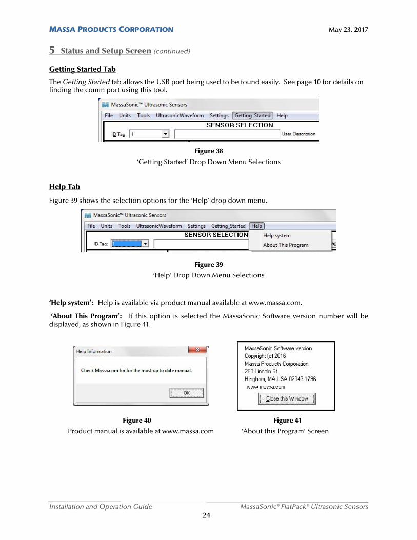
After clicking Continue in the Warning Display page, the sensor will obtain ultrasonic waveforms and display them one at a time as shown if Figure 34. The “Signal” trace, in black, represents the peak detected waveform from the received ultrasonic signals. The first peak is the sensor’s transmit pulse (which may not be present in dual transducer models), followed by a second peak at 21” that is the target. Subsequent reflections may follow the target signal, but they are ignored by the sensor. The 2nd trace in red is the ‘Threshold’ trace. This represents the signal detection level as determined by the “Sensitivity” setting. A reflected signal that crosses over this ‘Threshold’ level is captured and used to calculate the Target Distance. Most applications will have the “Sensitivity” adjustment set to “Normal”. However, if the target’s reflection is marginal, setting the “Sensitivity” setting to “High” (which lowers the threshold level) will improve target detection. On the other hand, if there are unwanted reflections in the application arriving before the target echo, setting the “Sensitivity” setting to “Low” (which raises the “Threshold” level) may be required. This valuable display tool will help to analyze and validate the sensor’s operation in the particular application. Certain applications may require custom sensitivity adjustments that can be done with the PLUS models. Consult Massa Products for additional information. Diagnostic waveforms can be saved and recalled using the ‘Save Data’ and ‘Recall Data’ from the File drop down menu. See Figure 35.
Figure 34 Ultrasonic Waveform
(1 of 2 waveforms available)
Figure 35 Saving and Recalling of Waveforms
Drop down menu items
MASSA PRODUCTS CORPORATION May 23, 2017
Installation and Operation Guide MassaSonic® FlatPack® Ultrasonic Sensors 23
5 Status and Setup Screen (continued)
Settings Tab
Figure 36 shows the selection options for the ‘Setting’ drop down menu
Figure 36
The ‘Settings’ Drop Down Menu Selections of the Status and Setup Screen
‘Display Default Settings’: Displays the Factory Default values. Either cancel or program these values into your sensor. You may change settings before programming the sensor.
‘Communications Port…’: Allows for selection of the PC port the USB Converter is assigned to. If it has not yet been determined, then use the Getting Started menu to have it automatically found.
‘Search Options…’: If ‘Search Options…’ is selected, the screen shown in Figure 37 is displayed. The MassaSonic Software will only search for sensors with ID Tag numbers between those listed in ‘Start Search ID Tag’ and ‘End Search ID Tag’. To change the search limits, click on the ‘Start Search ID Tag’ and ‘End Search ID Tag’ boxes and enter ID Tag values from 1 to 32 and click ‘OK’. To search for the new ID Tag search limits just entered, go to the ‘Tools’ drop down menu and then select ‘Search for Sensors - Options’. If all the sensors on line are not found, then revert back to searching from 1 to 32.
Figure 37
Example Showing the ‘Search for Sensors - Options’ Screen
MASSA PRODUCTS CORPORATION May 23, 2017
Installation and Operation Guide MassaSonic® FlatPack® Ultrasonic Sensors 24
5 Status and Setup Screen (continued)
Getting Started Tab
The Getting Started tab allows the USB port being used to be found easily. See page 10 for details on finding the comm port using this tool.
Figure 38
‘Getting Started’ Drop Down Menu Selections
Help Tab
Figure 39 shows the selection options for the ‘Help’ drop down menu.
Figure 39
‘Help’ Drop Down Menu Selections
‘Help system’: Help is available via product manual available at www.massa.com.
‘About This Program’: If this option is selected the MassaSonic Software version number will be displayed, as shown in Figure 41. Figure 40 Figure 41
Product manual is available at www.massa.com ‘About this Program’ Screen
MASSA PRODUCTS CORPORATION May 23, 2017
Installation and Operation Guide MassaSonic® FlatPack® Ultrasonic Sensors 25
6 Factory Default Programmed Settings The FlatPack Sensor is factory programmed with the default values listed below. All of the values can be reprogrammed if required by the application. The factory defaults are as follows: ID Tag = 1 User Description Field = 32 ASCII spaces Mode Selection for Voltage Output = Linear Voltage Output Linear Mode Settings:
1st Output Setpoint: Vout = 0.0 V (Iout models = 4 mA); Distance = *min specified sensing range 2nd Output Setpoint: Vout = 10.0 V (Iout models = 20 mA); Distance = *max specified sensing range No Echo Voltage = 10.25 V (Iout models = 20.5 mA)
Voltage Output Switch Mode Settings:
Close Setpoint Distance = *minimum sensing range Far Setpoint Distance = *maximum sensing range Volts Out Switch State = 0 V DC for all zones Maximum Sensing Range for Switch Mode = *maximum sensing range Hysteresis = 5%
Sampling Settings:
Trigger Mode = internal Average type = boxcar Average = 1 sample Sample Rate = 10 samples/sec. (Hz) No Echo Time Out = 1 sample (0.10 sec.) Sensitivity = normal
Miscellaneous:
Temperature Compensation = automatic (internal probe) Other parameters:
Self-heating Correction = enabled (checked) * Minimum and Maximum sensing ranges are different for each model in the FlatPack Sensor Family.
Consult the datasheet located on the Massa website (www.massa.com) for the specific sensor model to obtain its minimum and maximum sensing ranges.
7 Specifications There are several different models in the FlatPack Sensor Family. The latest specifications for each
sensor are posted on the Massa website (www.massa.com).
MASSA PRODUCTS CORPORATION May 23, 2017
Installation and Operation Guide MassaSonic® FlatPack® Ultrasonic Sensors 26
8 Troubleshooting The Setpoint Output is erratic when the target is at the programmed setpoint:
Set the ‘Hysteresis’ to a nominal value of 5%. Cannot find all sensors that are connected in a multi-drop network:
Verify the communications adapter is wired properly. Verify that unique ID tags were assigned for each sensor on line. Verify that range of ‘ID Tags’ entered in the ‘Search for Sensors’ screen is 1 to 32 (see Figure 37).
The Voltage Output does not respond:
Verify that power is connected to the sensor. Verify that the sensor in not in the Manual trigger mode.
Sensor reports ‘zero’ range and ‘No Target’ when the target should be detected:
If the sensor is programmed for ‘Switch Mode’ operation the target could be beyond the Far Zone. Under these circumstances, the sensor will report ‘Zero’ range and ‘No Target’. Adjust the parameter ‘Maximum Sensing Range for Switch Mode’.
The sensor seems to respond slowly or erratically:
The ‘Average’ may be set to a high value and/or the ’Sample Rate’ may be set to a slow rate. There is a balance required for adjusting these parameters. Each sensor must be adjusted to each application based on process speed (‘Sample Rate’), the smoothness required of the outputs (‘Average’) and occasional loss of echo filtering (‘No Echo Time Out’).
9 Terminology Beam: The projection, usually conical, of useable ultrasonic energy radiating from the
sensor that extends axially from the face of the transducer in the sensor.
Beam Diameter: The diameter, dia (D), as a function of distance, D, of the cross-sectional area insonified by a sensor with an acoustic system beam angle of , computed as follows (for value of , see Table in Section 1 or the datasheet for the specific model of sensor on the Massa website at www.massa.com):
( ) 2 tan2
dia D D
Close Setpoint A position in space within the sonar’s beam that is closer than the Far Setpoint Distance Distance, and between the Minimum Sensing Range and the Maximum Sensing Range (see Figure 8). Far Setpoint A position in space beyond the Close Setpoint Distance, and between the Distance: Maximum Sensing Range and the Minimum Sensing Range (see Figure 8). Half Duplex: Operation of a communication network in which access on the line only occurs
one at a time (due to a 2 wire system). This requires full software control on the line, typically the PC or host controls the data flow. This is the operation of the MassaSonic™ Software with the sensors.
MASSA PRODUCTS CORPORATION May 23, 2017
Installation and Operation Guide MassaSonic® FlatPack® Ultrasonic Sensors 27
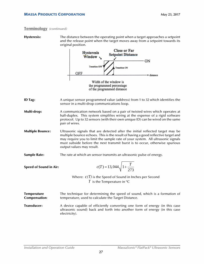
Terminology (continued) Hysteresis: The distance between the operating point when a target approaches a setpoint
and the release point when the target moves away from a setpoint towards its original position.
ID Tag: A unique sensor programmed value (address) from 1 to 32 which identifies the
sensor in a multi-drop communications loop. Multi-drop: A communication network based on a pair of twisted wires which operates at
half-duplex. This system simplifies wiring at the expense of a rigid software protocol. Up to 32 sensors (with their own unique ID) can be wired on the same pair of wires.
Multiple Bounce: Ultrasonic signals that are detected after the initial reflected target may be
multiple bounce echoes. This is the result of having a good reflective target and may require you to limit the sample rate of your system. All ultrasonic signals must subside before the next transmit burst is to occur, otherwise spurious output values may result.
Sample Rate: The rate at which an sensor transmits an ultrasonic pulse of energy.
Speed of Sound in Air: ( ) 13,044 1273
Tc T
Where: c(T) is the Speed of Sound in Inches per Second T is the Temperature in ºC Temperature The technique for determining the speed of sound, which is a formation of Compensation: temperature, used to calculate the Target Distance. Transducer: A device capable of efficiently converting one form of energy (in this case
ultrasonic sound) back and forth into another form of energy (in this case electricity).
MASSA PRODUCTS CORPORATION May 23, 2017
Installation and Operation Guide MassaSonic® FlatPack® Ultrasonic Sensors 28
10 Wire Color Code Wire Color Code for Standard FlatPack™ Sensors: RED: 12 - 24 V DC
BLACK: Ground WHITE: Vout (or Iout for current output models) GREEN: RS-485 communications port, A (-) or TDA (-) terminal BROWN: RS-485 communications port, B (+) or TDB (+) terminal SHIELD: Ground
11 Customer Support Massa Products Corporation 280 Lincoln Street Hingham, MA 02043 USA
Tel: (781) 749-4800 Fax: (781) 740-2045 Toll Free in the USA: 800-962-7543
Hours: 8:00am to 4:30pm (Eastern Standard Time)
Website: www.massa.com Email: [email protected]
12 Warranty MASSA PRODUCTS CORPORATION, hereinafter called MASSA, warrants each of its products to be free from defects in material and workmanship for a period of one year commencing on the date of delivery to the original Purchaser. The obligation under this warranty is limited to the repair or replacement at MASSA’S sole discretion of any MASSA product returned to MASSA or to an authorized field service station. OTHER THAN AS SET FORTH ABOVE, MASSA MAKES NO WARRANTY REGARDING ITS PRODUCTS (INCLUDING, WITHOUT LIMITATION, WARRANTIES AS TO MERCHANTABILITY AND FITNESS FOR A PARTICULAR PURPOSE) EITHER EXPRESS OR IMPLIED. MASSA SPECIFICALLY MAKES NO WARRANTIES AS TO THE SUITABILITY OF THE PRODUCTS FOR ANY PARTICULAR APPLICATION, WHETHER FOR PURCHASER OR PURCHASER’S CUSTOMERS. Massa Products Corporation reserves the right to change system and performance specifications without notice.
MASSA PRODUCTS CORPORATION May 23, 2017
Installation and Operation Guide MassaSonic® FlatPack® Ultrasonic Sensors 29
Appendix A Sensor Start up Timing
The sensor power up time ready to report a valid output is based on several sensor settings and target conditions. These include Sample Rate, Average, and No Echo Timeout. The following are formulas based on these settings and conditions:
Model FlatPack™ with minimum sensing range enabled:
Sensor Startup Time (valid target): 0.25 seconds + (2 x Average x Sample Rate in seconds)
Sensor Startup Time (no target): 0.25 seconds + (2 x No Echo x Sample Rate in seconds)
Model FlatPack™ with minimum sensing range disabled:
Sensor Startup Time (valid target): 0.25 seconds + (Average Setting x Sample Rate in seconds)
Sensor Startup Time (no target): 0.25 seconds + (No Echo Setting x Sample Rate in seconds)
Appendix B
RS-485 Converters
Note 1: The RS-485 Converter must have automatic send data control for proper operation. Sensors are configured for half-duplex operation (2-wire), which allows only one device to communicate at a time. In normal operation a host device (typically a PC) requests data or sends a command to a particular sensor resulting in a response.