flatcam: thin, bare-sensor cameras using coded aperture ... · 1 flatcam: thin, bare-sensor cameras...
TRANSCRIPT
1
FlatCam: Thin, Bare-Sensor Cameras using Coded Aperture andComputation
M. Salman Asif,1 Ali Ayremlou,1 Aswin Sankaranarayanan,2 Ashok Veeraraghavan,1 and Richard Baraniuk1
1Department of Electrical and Computer Engineering, Rice University, Houston, TX 77005, USA2Department of Electrical and Computer Engineering, Carnegie Mellon University, Pittsburgh, PA 15213, USA
FlatCam is a thin form-factor lensless camera that consists of a coded mask placed on top of a bare, conventional sensor array.Unlike a traditional, lens-based camera where an image of the scene is directly recorded on the sensor pixels, each pixel in FlatCamrecords a linear combination of light from multiple scene elements. A computational algorithm is then used to demultiplex therecorded measurements and reconstruct an image of the scene. FlatCam is an instance of a coded aperture imaging system; however,unlike the vast majority of related work, we place the coded mask extremely close to the image sensor that can enable a thin system.We employ a separable mask to ensure that both calibration and image reconstruction are scalable in terms of memory requirementsand computational complexity. We demonstrate the potential of the FlatCam design using two prototypes: one at visible wavelengthsand one at infrared wavelengths.
I. INTRODUCTION
A range of new imaging applications is driving the minia-turization of cameras. As a consequence, significant progresshas been made towards minimizing the total volume of thecamera, which has enabled new applications in endoscopy, pillcameras, and in vivo microscopy. Unfortunately, this strategyof miniaturization has an important shortcoming: the amountof light collected at the sensor decreases dramatically asthe lens aperture and the sensor size become smaller. As aconsequence, ultra-miniature imagers built simply by scalingdown the optics and sensors suffer from extremely low lightcollection.
In this paper, we present a camera architecture that wecall FlatCam, which is inspired by coded aperture imagingprinciples pioneered in astronomical x-ray and gamma-rayimaging [1]–[4]. Our proposed FlatCam design uses a verylarge photosensitive area with a very thin form factor. TheFlatCam achieves thin form factor by dispensing with a lensand replacing it with a coded, binary mask placed almostimmediately atop a bare conventional sensor array. The imageformed on the sensor can be viewed as a superposition of manypinhole images. Thus, the light collection ability of such acoded aperture system is proportional to the size of the sensorand the transparent regions (pinholes) in the mask. In contrast,the light collection ability of a miniature, lens-based camerais limited by the lens aperture size, which is restricted by therequirements on the device thickness.
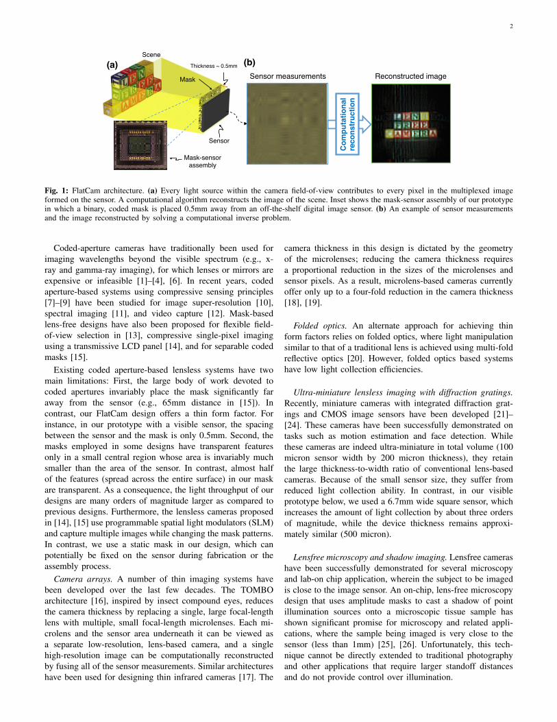
An illustration of the FlatCam design is presented in Fig. 1.Light from a scene passes through a coded mask and lands ona conventional image sensor. The mask consists of opaque andtransparent features (to block and transmit light, respectively);each transparent feature can be viewed as a pinhole. Lightfrom the scene gets diffracted by the mask features such thatlight from each scene location casts a unique mask shadow onthe sensor, and this mapping can be represented using a linearoperator. A computational algorithm then inverts this linear
Corresponding author: M. Salman Asif (email: [email protected]).
operator to recover the original light distribution of the scenefrom the sensor measurements.
Our FlatCam design has many attractive properties besidesits slim profile. First, since it reduces the thickness of thecamera but not the area of the sensor, it collects more light thanminiature, lens-based cameras with same thickness. Second,the mask can be created from inexpensive materials thatoperate over a broad range of wavelengths. Third, the mask canbe fabricated simultaneously with the sensor array, creatingnew manufacturing efficiencies. The mask can be fabricatedeither directly in one of the metal interconnect layers on topof the photosensitive layer or on a separate wafer thermalcompression that is bonded to the back side of the sensor,as is typical for back-side illuminated image sensors [5].
We demonstrate the potential of the FlatCam using twoprototypes built in our laboratory with commercially availablesensors and masks: a visible prototype in which the mask-sensor spacing is about 0.5mm and a short-wave infrared(SWIR) prototype in which the spacing is about 5mm. Figures4 and 8 illustrate sensor measurements and reconstructedimages using our prototype FlatCams.
II. RELATED WORK
Pinhole cameras. Imaging without a lens is not a new idea.Pinhole cameras, the progenitor of lens-based cameras, havebeen well known since Alhazen (965–1039AD) and Mozi(c. 370BCE). However, a tiny pinhole drastically reduces theamount of light reaching the sensor, resulting in noisy, low-quality images. Indeed, lenses were introduced into camerasfor precisely the purpose of increasing the size of the aperture,and thus the light throughput, without degrading the sharpnessof the acquired image.
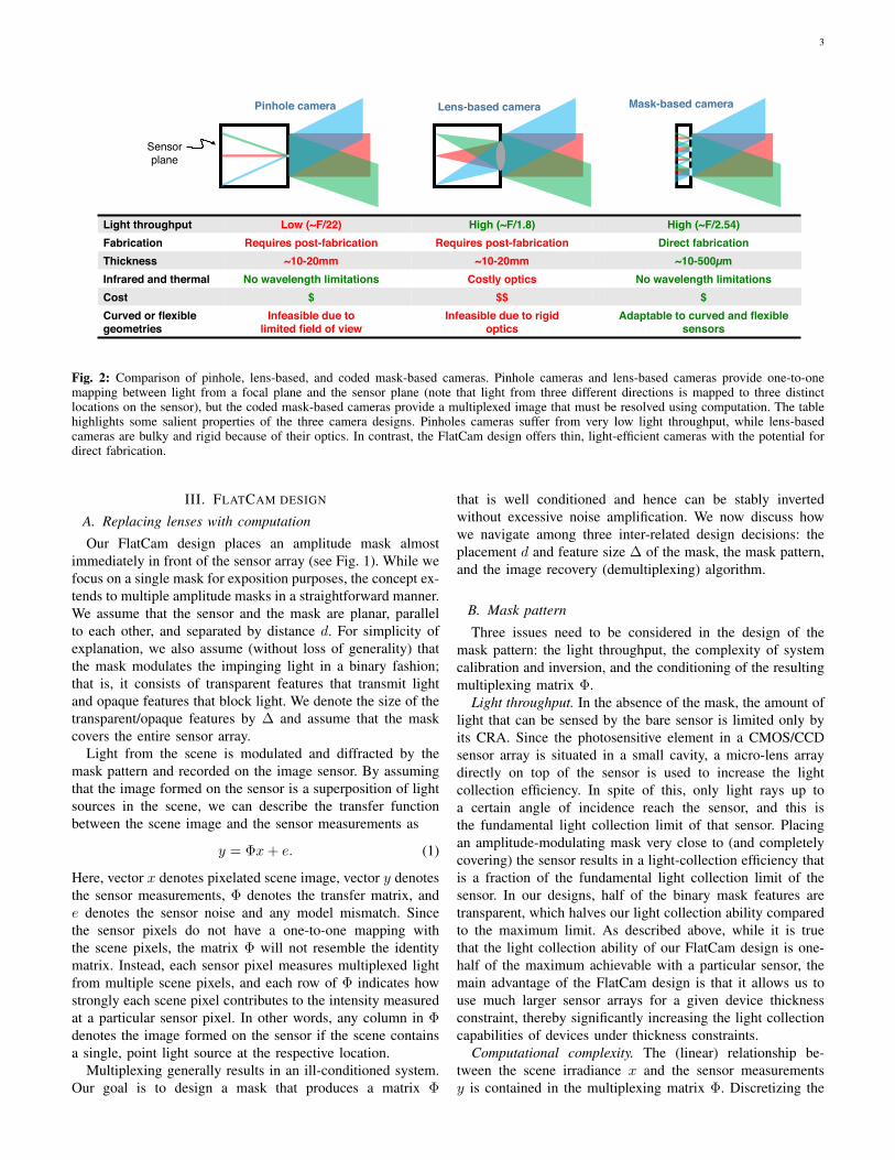
Coded apertures. Coded aperture cameras extend the idea ofa pinhole camera by using masks with multiple pinholes [1]–[3]. The primary goal of coded aperture cameras is to increasethe light throughput compared to a pinhole camera. Figure 2summarizes some salient features of pinhole, lens-based, andFlatCam (coded mask-based) architectures.
arX
iv:1
509.
0011
6v1
[cs
.CV
] 1
Sep
201
5
2
(a)!Scene!
Mask!
Sensor!
Thickness ~ 0.5mm!
Mask-sensor !assembly!
Sensor measurements! Reconstructed image!(b)!
Com
puta
tiona
l !re
cons
truc
tion!
Fig. 1: FlatCam architecture. (a) Every light source within the camera field-of-view contributes to every pixel in the multiplexed imageformed on the sensor. A computational algorithm reconstructs the image of the scene. Inset shows the mask-sensor assembly of our prototypein which a binary, coded mask is placed 0.5mm away from an off-the-shelf digital image sensor. (b) An example of sensor measurementsand the image reconstructed by solving a computational inverse problem.
Coded-aperture cameras have traditionally been used forimaging wavelengths beyond the visible spectrum (e.g., x-ray and gamma-ray imaging), for which lenses or mirrors areexpensive or infeasible [1]–[4], [6]. In recent years, codedaperture-based systems using compressive sensing principles[7]–[9] have been studied for image super-resolution [10],spectral imaging [11], and video capture [12]. Mask-basedlens-free designs have also been proposed for flexible field-of-view selection in [13], compressive single-pixel imagingusing a transmissive LCD panel [14], and for separable codedmasks [15].
Existing coded aperture-based lensless systems have twomain limitations: First, the large body of work devoted tocoded apertures invariably place the mask significantly faraway from the sensor (e.g., 65mm distance in [15]). Incontrast, our FlatCam design offers a thin form factor. Forinstance, in our prototype with a visible sensor, the spacingbetween the sensor and the mask is only 0.5mm. Second, themasks employed in some designs have transparent featuresonly in a small central region whose area is invariably muchsmaller than the area of the sensor. In contrast, almost halfof the features (spread across the entire surface) in our maskare transparent. As a consequence, the light throughput of ourdesigns are many orders of magnitude larger as compared toprevious designs. Furthermore, the lensless cameras proposedin [14], [15] use programmable spatial light modulators (SLM)and capture multiple images while changing the mask patterns.In contrast, we use a static mask in our design, which canpotentially be fixed on the sensor during fabrication or theassembly process.
Camera arrays. A number of thin imaging systems havebeen developed over the last few decades. The TOMBOarchitecture [16], inspired by insect compound eyes, reducesthe camera thickness by replacing a single, large focal-lengthlens with multiple, small focal-length microlenses. Each mi-crolens and the sensor area underneath it can be viewed asa separate low-resolution, lens-based camera, and a singlehigh-resolution image can be computationally reconstructedby fusing all of the sensor measurements. Similar architectureshave been used for designing thin infrared cameras [17]. The
camera thickness in this design is dictated by the geometryof the microlenses; reducing the camera thickness requiresa proportional reduction in the sizes of the microlenses andsensor pixels. As a result, microlens-based cameras currentlyoffer only up to a four-fold reduction in the camera thickness[18], [19].
Folded optics. An alternate approach for achieving thinform factors relies on folded optics, where light manipulationsimilar to that of a traditional lens is achieved using multi-foldreflective optics [20]. However, folded optics based systemshave low light collection efficiencies.
Ultra-miniature lensless imaging with diffraction gratings.Recently, miniature cameras with integrated diffraction grat-ings and CMOS image sensors have been developed [21]–[24]. These cameras have been successfully demonstrated ontasks such as motion estimation and face detection. Whilethese cameras are indeed ultra-miniature in total volume (100micron sensor width by 200 micron thickness), they retainthe large thickness-to-width ratio of conventional lens-basedcameras. Because of the small sensor size, they suffer fromreduced light collection ability. In contrast, in our visibleprototype below, we used a 6.7mm wide square sensor, whichincreases the amount of light collection by about three ordersof magnitude, while the device thickness remains approxi-mately similar (500 micron).
Lensfree microscopy and shadow imaging. Lensfree camerashave been successfully demonstrated for several microscopyand lab-on chip application, wherein the subject to be imagedis close to the image sensor. An on-chip, lens-free microscopydesign that uses amplitude masks to cast a shadow of pointillumination sources onto a microscopic tissue sample hasshown significant promise for microscopy and related appli-cations, where the sample being imaged is very close to thesensor (less than 1mm) [25], [26]. Unfortunately, this tech-nique cannot be directly extended to traditional photographyand other applications that require larger standoff distancesand do not provide control over illumination.
3
Mask-based camera!Pinhole camera! Lens-based camera!
Sensor!plane!
Light throughput! Low (~F/22)! High (~F/1.8)! High (~F/2.54)!Fabrication! Requires post-fabrication ! Requires post-fabrication ! Direct fabrication!Thickness! ~10-20mm! ~10-20mm! ~10-500µm!Infrared and thermal! No wavelength limitations! Costly optics! No wavelength limitations!Cost! $! $$! $!Curved or flexible geometries!
Infeasible due to limited field of view!
Infeasible due to rigid !optics!
Adaptable to curved and flexible sensors!
Fig. 2: Comparison of pinhole, lens-based, and coded mask-based cameras. Pinhole cameras and lens-based cameras provide one-to-onemapping between light from a focal plane and the sensor plane (note that light from three different directions is mapped to three distinctlocations on the sensor), but the coded mask-based cameras provide a multiplexed image that must be resolved using computation. The tablehighlights some salient properties of the three camera designs. Pinholes cameras suffer from very low light throughput, while lens-basedcameras are bulky and rigid because of their optics. In contrast, the FlatCam design offers thin, light-efficient cameras with the potential fordirect fabrication.
III. FLATCAM DESIGN
A. Replacing lenses with computation
Our FlatCam design places an amplitude mask almostimmediately in front of the sensor array (see Fig. 1). While wefocus on a single mask for exposition purposes, the concept ex-tends to multiple amplitude masks in a straightforward manner.We assume that the sensor and the mask are planar, parallelto each other, and separated by distance d. For simplicity ofexplanation, we also assume (without loss of generality) thatthe mask modulates the impinging light in a binary fashion;that is, it consists of transparent features that transmit lightand opaque features that block light. We denote the size of thetransparent/opaque features by ∆ and assume that the maskcovers the entire sensor array.
Light from the scene is modulated and diffracted by themask pattern and recorded on the image sensor. By assumingthat the image formed on the sensor is a superposition of lightsources in the scene, we can describe the transfer functionbetween the scene image and the sensor measurements as
y = Φx+ e. (1)
Here, vector x denotes pixelated scene image, vector y denotesthe sensor measurements, Φ denotes the transfer matrix, ande denotes the sensor noise and any model mismatch. Sincethe sensor pixels do not have a one-to-one mapping withthe scene pixels, the matrix Φ will not resemble the identitymatrix. Instead, each sensor pixel measures multiplexed lightfrom multiple scene pixels, and each row of Φ indicates howstrongly each scene pixel contributes to the intensity measuredat a particular sensor pixel. In other words, any column in Φdenotes the image formed on the sensor if the scene containsa single, point light source at the respective location.
Multiplexing generally results in an ill-conditioned system.Our goal is to design a mask that produces a matrix Φ
that is well conditioned and hence can be stably invertedwithout excessive noise amplification. We now discuss howwe navigate among three inter-related design decisions: theplacement d and feature size ∆ of the mask, the mask pattern,and the image recovery (demultiplexing) algorithm.
B. Mask pattern
Three issues need to be considered in the design of themask pattern: the light throughput, the complexity of systemcalibration and inversion, and the conditioning of the resultingmultiplexing matrix Φ.
Light throughput. In the absence of the mask, the amount oflight that can be sensed by the bare sensor is limited only byits CRA. Since the photosensitive element in a CMOS/CCDsensor array is situated in a small cavity, a micro-lens arraydirectly on top of the sensor is used to increase the lightcollection efficiency. In spite of this, only light rays up toa certain angle of incidence reach the sensor, and this isthe fundamental light collection limit of that sensor. Placingan amplitude-modulating mask very close to (and completelycovering) the sensor results in a light-collection efficiency thatis a fraction of the fundamental light collection limit of thesensor. In our designs, half of the binary mask features aretransparent, which halves our light collection ability comparedto the maximum limit. As described above, while it is truethat the light collection ability of our FlatCam design is one-half of the maximum achievable with a particular sensor, themain advantage of the FlatCam design is that it allows us touse much larger sensor arrays for a given device thicknessconstraint, thereby significantly increasing the light collectioncapabilities of devices under thickness constraints.
Computational complexity. The (linear) relationship be-tween the scene irradiance x and the sensor measurementsy is contained in the multiplexing matrix Φ. Discretizing the
4
unknown scene irradiance into N×N pixel units and assumingan M × M sensor array, Φ is an M2 × N2 matrix. Givena mask and sensor, we can obtain the entries of Φ either bymodeling the transmission of light from the scene to the sensoror through a calibration process. Clearly, even for moderatelysized systems, Φ is prohibitively large to either estimate(calibration) or invert (image reconstruction), in general. Forexample, to describe a system with a megapixel resolutionscene and a megapixel sensor array, Φ will contain on theorder of 106 × 106 = 1012 elements.
One way to reduce the complexity of Φ is to use a separablemask for the FlatCam system. If the mask pattern is separable(i.e., an outer product of two one-dimensional patterns), thenthe imaging system in (1) can be rewritten as
Y = ΦLXΦTR + E, (2)
where ΦL,ΦR denote matrices that correspond to one-dimensional convolution along the rows and columns of thescene, respectively, X is an N × N matrix containing thescene radiance, Y in an M ×M matrix containing the sensormeasurements, and E denotes the sensor noise and any modelmismatch. For a megapixel scene and a megapixel sensor,ΦL and ΦR have only 106 elements each, as opposed to1012 elements in Φ. Similar idea has been recently proposedin [15] with the design of doubly toeplitz mask. In ourimplementation, we also estimate the system matrices usinga separate calibration procedure (see Sec. III-D), which alsobecomes significantly simpler for a separable system.
Conditioning. The mask pattern should be chosen to makethe multiplexing matrices ΦL and ΦR as numerically stable aspossible, which ensures a stable recovery of the image X fromthe sensor measurements Y . Such ΦL and ΦR should havelow condition numbers, i.e., a flat singular value spectrum.For Toeplitz matrices, it is well known that, of all binarysequences, the so-called maximum length sequences, or M-sequences, have maximally flat spectral properties [27]. There-fore, we use a separable mask pattern that is the outer productof two one-dimensional M-sequence patterns. However, be-cause of the inevitable non-idealities in our implementation,such as the limited sensor CRA and the larger than optimalsensor-mask distance due to the hot mirror, the actual ΦL andΦR we obtain using a separable M-sequence based mask donot achieve a perfectly flat spectral profile. Nevertheless, aswe demonstrate in our prototypes, the resulting multiplexingmatrices enable stable image reconstruction in the presence ofsensor noise and other non-idealities. All of the visible wave-length, color image results shown in this paper were obtainedusing normal, indoor ambient lighting and exposure times in10–20ms range, demonstrating that robust reconstruction ispossible.
C. Mask placement and feature size
The multiplexing matrices ΦL,ΦR describe the mapping oflight emanating from the points in the scene to the pixels onthe sensor. Consider light from a point source passing throughone of the mask openings; its intensity distribution recordedat the sensor forms a point-spread function (PSF) that is due
to both diffraction and geometric blurs. The PSF acts as alow-pass filter that limits the frequency content that can berecovered from the sensor measurements. The choice of thefeature size and mask placement is dictated by the tradeoffbetween two factors: reducing the size of the PSF to minimizethe total blur and enabling sufficient multiplexing to obtain awell-conditioned linear system.
The total size of the PSF depends on the diffraction andgeometric blurs, which in turn depend on the distance betweenthe sensor and the mask, d, and the mask feature size, ∆. Thesize of the diffraction blur is directly proportional to d andinversely proportional to ∆. The size of the geometric blur,however, is equal to the feature size ∆. This implies that theminimum blur radius is achieved when the two blur sizes areapproximately equal. One possible way to reduce the size ofthe combined PSF is to move the mask closer to the sensor.However, the extent of multiplexing within the scene pixelsshrinks as the mask moves closer to the sensor. Therefore,if we aim to keep the amount of multiplexing constant, thenthe mask feature size ∆ should shrink proportionally to themask-sensor distance d.
In practice, physical limits on the sensor-mask distance dor the mask feature size ∆ can dictate the design choices. Inour visible FlatCam prototype, for example, we use a SonyICX285 sensor. The sensor has a 0.5mm thick hot mirrorattached to the top of the sensor, which restricts the potentialspacing between the mask and sensor surface. Therefore, weplace the mask immediately atop the hot mirror, resultingin d ≈ 500µm (distance between the mask and the sensorsurface). We achieved the smallest total blur size using a maskfeature size of approximately ∆ = 30µm. Of course, in futureimplementations, where the mask pattern is directly etched ontop of the image sensor (direct fabrication) such a thicknessconstraint does not exist and we can achieve much higherresolution images by moving the mask closer to the sensorand reducing the mask feature size proportionally.
D. Camera calibration
We now provide the details of our calibration procedurefor the separable imaging system modeled in (2). Instead ofmodeling the convolution shifts and diffraction effects for aparticular mask-sensor arrangement, we directly estimate thesystem matrices.
To align the mask and sensor, we adjust their relativeorientation such that a separable scene in front of the camerayields a separable image on the sensor. For a coarse alignment,we use a point light source, which projects a shadow of themask onto the sensor, and align the horizontal and verticaledges on the sensor image with the image axes. For a finealignment, we align the sensor with the mask while projectinghorizontal and vertical stripes on a monitor or screen in thefront of the camera.
To calibrate a system that can recover N×N images X , weestimate the left and right matrices ΦL,ΦR using the sensormeasurements of 2N known calibration patterns projected ona screen as depicted in Fig. 3. Our calibration procedure relies

5
on an important observation. If the scene X is separable, i.e.,X = abT where a,b ∈ RN , then
Y = ΦLabT ΦT
R = (ΦLa)(ΦRb)T .
In essence, the image formed on the sensor is a rank-1 matrix,and by using a truncated singular value decomposition (SVD),we can obtain ΦLa and ΦRb up to a signed, scalar constant.We take N separable pattern measurements for calibratingeach of ΦL and ΦR.
Specifically, to calibrate ΦL, we capture N images{Y1, . . . , YN} corresponding to the separable patterns{X1, . . . , XN} displayed on a monitor or screen. Each Xk isof the form Xk = hk1
T , where hk ∈ RN is a column of theorthogonal Hadamard matrix H of size N×N and 1 is an all-ones vector of length N . Since the Hadamard matrix consistsof ±1 entries, we record two images for each Hadamardpattern; one with hk1
T and one with −hk1T while setting
the negative entries to zero in both cases. We then subtract thetwo sensor images to obtain the measurements correspondingto Xk. Let Yk = ukv
T be the rank-1 approximation of themeasurements Yk obtained via SVD, where the underlyingassumption is that v ≈ ΦR1, upto a signed, scalar constant.Then, we have
[u1 u2 · · ·uN ] = ΦL[h1 h2 · · ·hN ] ≡ ΦLH, (3)
and we compute ΦL as
ΦL = [u1 u2 · · ·uN ]H−1, (4)
where H−1 = 1NH
T . Similarly, we estimate ΦR by projectingN patterns of the form 1hT
k .Figure 3 depicts the calibration procedure in which we
projected separable patterns on a screen and recorded sensormeasurements; the sensor measurements recorded from thesepatterns are re-ordered to form the left and right multiplexingoperators shown in (b).
A mask modulates light only by non-negative values. M-sequences are defined in terms of ±1 values and hence cannotbe directly implemented in a mask. The masks we use in ourprototype cameras are constructed by computing the outer-product of two M-sequences and then setting the resulting −1entries to 0. This produces a mask that is optically feasiblebut no longer mathematically separable. We can resolve thisissue in post-processing, since the difference between themeasurements using the theoretical ±1 separable mask andthe optically feasible 0/1 mask is simply a constant bias term.In practice, once we acquire a sensor image, we correct it tocorrespond to a ±1 separable mask (described as Y in (2))simply by forcing the column and row sums to zero.
IV. IMAGE RECONSTRUCTION
Given a set of M ×M sensor measurements Y , our abilityto invert the system (2) to recover the desired N ×N imageX primarily depends on the rank and the condition number ofthe system matrices ΦL, ΦR.
If both ΦL and ΦR are well-conditioned, then we canestimate X by solving a simple least-squares problem
XLS = arg minX‖ΦLXΦT
R − Y ‖22, (5)
(b)!
�L
Left system !matrix !!
�TR
Horizontal !patterns yield!
Vertical patterns
yield!
Right system !matrix!
(a)!
Separable Hadamard patterns!
eY = �LX�TRSensor measurements: !
Screen!Separable mask !
on sensor!
Fig. 3: Calibration for measuring the left and right multiplexingmatrices ΦL and ΦR corresponding to a separable mask. (a) Displayseparable patterns on a screen. The patterns are orthogonal, one-dimensional Hadamard codes that are repeated along either thehorizontal or vertical direction. (b) Estimated left and right systemmatrices.
which has the closed form solution: XLS = Φ+LY Φ+
R, whereΦ+
L and Φ+R denote the pseudoinverse of ΦL and ΦR, re-
spectively. Consider the SVD of ΦL = ULΣLVTL , where UL
and VL are orthogonal matrices that contain the left and rightsingular vectors and ΣL is a diagonal matrix that contains thesingular values. Note that this SVD need only be computedonce for each calibrated system. The pseudoinverse can thenbe efficiently pre-computed as Φ+
L = VLΣ−1L UT
L .When the matrices ΦL, ΦR are not well-conditioned or are
under-determined (e.g., when we have fewer measurementsM than the desired dimensionality of the scene N , as incompressive sensing [7]–[9]), some of the singular valuesare either very small or equal to zero. In these cases, theleast-squares estimate XLS suffers from noise amplification.A simple approach to reduce noise amplification is to add an`2 regularization term in the least-squares problem in (5)
XTik = arg minX‖ΦLXΦT
R − Y ‖22 + τ‖X‖22, (6)
where τ > 0 is a regularization parameter. The solution of (6)can also be explicitly written using the SVD of ΦL and ΦR
as we describe below.The solution of (6) can be computed by setting the gradient
of the objective in (6) equal to zero and simplifying theresulting equation:
ΦTL(ΦLXΦT
R − Y )ΦR + τX = 0
ΦTLΦLXΦT
RΦR + τX = ΦTLY ΦR.
Replacing ΦL and ΦR with their SVD decompositions yields
VLΣ2LV
TL XVRΣ2
RVTR + τX = VLΣLU
TL Y URΣRV
TR .
Multiplying both sides of the equation with V TL from the left
and VR from the right yields
Σ2LV
TL XVRΣ2
R + τV TL XVR = ΣLU
TL Y URΣR.
6
Denote the diagonal entries of Σ2L and Σ2
R using the vectorsσL and σR, respectively, to simplify the equations to
V TL XVR � (σLσ
TR) + τV T
L XVR = ΣLUTL Y URΣR
V TL XVR � (σLσ
TR + τ11T ) = ΣLU
TL Y URΣR
V TL XVR = (ΣLU
TL Y URΣR)./(σLσ
TR + τ11T ),
where A � B and A./B denote element-wise multiplicationand division of matrices A and B, respectively. The solutionof (6) can finally be written as
XTik = VL[(ΣLUTL Y URΣR)./(σLσ
TR + τ11T )]V T
R . (7)
Thus, once the SVDs of ΦL and ΦR are computed and stored,reconstruction of an N × N image from M × M sensormeasurements involves a fixed cost of two M × N matrixmultiplications, two N ×N matrix multiplications, and threeN ×N diagonal matrix multiplications.
In many cases, exploiting the sparse or low-dimensionalstructure of the unknown image significantly enhances re-construction performance. Natural images and videos exhibita host of geometric properties, including sparse gradientsand sparse coefficients in certain transform domains. Waveletsparse models and total variation (TV) are widely used regu-larization methods for natural images [28], [29]. By enforcingthese geometric properties, we can suppress noise amplifica-tion as well as obtain unique solutions. A pertinent examplefor image reconstruction is the sparse gradient model, whichcan be represented in the form of the following total-variation(TV) minimization problem:
XTV = arg minX‖ΦLXΦT
R − Y ‖2 + λ‖X‖TV. (8)
The term ‖X‖TV denotes the TV of the image X given by thesum of magnitudes of the image gradients. Given the sceneX as a 2D image, i.e., X(u, v), we can define Gu = DuXand Gv = DvX as the spatial gradients of the image alongthe horizontal and vertical directions, respectively. The totalvariation of the image is then defined as
‖X‖TV =∑
u,v
√Gu(u, v)2 +Gv(u, v)2.
Minimizing the TV as in (8) produces images with sparsegradients. The optimization problem (8) is convex and can beefficiently solved using a variety of methods. Many extensionsand performance analyses are possible following the recentlydeveloped theory of compressive sensing.
In addition to simplifying the calibration task, separabilityof the coded mask also significantly reduces the computationalburden of image reconstruction. Iterative methods for solvingthe optimization problems described above require the re-peated application of the multiplexing matrix and its transpose.Continuing our numerical example from above, for a non-separable, dense mask, both of these operations would requireon the order of 1012 multiplications and additions for mega-pixel images. With a separable mask, however, the applicationof the forward and transpose operators requires only on theorder of 2 × 10⁹ scalar multiplications and additions—atremendous reduction in computational complexity.
V. EXPERIMENTAL RESULTS
We present results on two prototypes. The first uses aSilcon-based sensor to sense in visible wavelengths and thesecond uses an InGaAs sensor for sensing in short-waveinfrared.
A. Visible wavelength FlatCam prototype
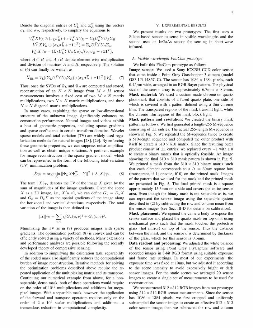
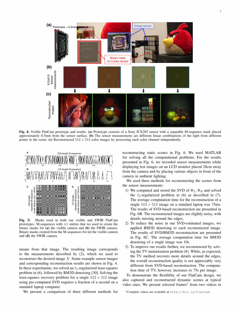
We built this FlatCam prototype as follows.Image sensor: We used a Sony ICX285 CCD color sensorthat came inside a Point Grey Grasshopper 3 camera (modelGS3-U3-14S5C-C). The sensor has 1036× 1384 pixels, each6.45µm wide, arranged in an RGB Bayer pattern. The physicalsize of the sensor array is approximately 6.7mm × 8.9mm.Mask material: We used a custom-made chrome-on-quartzphotomask that consists of a fused quartz plate, one side ofwhich is covered with a pattern defined using a thin chromefilm. The transparent regions of the mask transmit light, whilethe chrome film regions of the mask block light.Mask pattern and resolution: We created the binary maskpattern as follows. We first generated a length-255 M-sequenceconsisting of ±1 entries. The actual 255-length M-sequence isshown in Fig. 5. We repeated the M-sequence twice to createa 510-length sequence and computed the outer product withitself to create a 510 × 510 matrix. Since the resulting outerproduct consist of ±1 entries, we replaced every −1 with a 0to create a binary matrix that is optically feasible. An imageshowing the final 510× 510 mask pattern is shown in Fig. 5.We printed a mask from the 510 × 510 binary matrix suchthat each element corresponds to a ∆ = 30µm square box(transparent, if 1; opaque, if 0) on the printed mask. Imagesof the pattern that we used for the mask and the printed maskare presented in Fig. 5. The final printed mask is a squareapproximately 15.3mm on a side and covers the entire sensorarea. Even though the binary mask is not separable as is, wecan represent the sensor image using the separable systemdescribed in (2) by subtracting the row and column mean fromthe sensor images (see Sec. III-D for details on calibration).Mask placement: We opened the camera body to expose thesensor surface and placed the quartz mask on top of it usingmechanical posts such that the mask touches the protectiveglass (hot mirror) on top of the sensor. Thus the distancebetween the mask and the sensor d is determined by thicknessof the glass, which for this sensor is 0.5mm.Data readout and processing: We adjusted the white balanceof the sensor using Point Grey FlyCapture software andrecorded images in 8-bit RGB format using suitable exposureand frame rate settings. In most of our experiments, theexposure time was fixed at 10ms, but we adjusted it accordingto the scene intensity to avoid excessively bright or darksensor images. For the static scenes we averaged 20 sensorimages to create a single set of measurements to be used forreconstruction.
We reconstructed 512×512 RGB images from our prototypeusing 512× 512 RGB sensor measurements. Since the sensorhas 1086 × 1384 pixels, we first cropped and uniformlysubsampled the sensor image to create an effective 512× 512color sensor image; then we subtracted the row and column
7
512x
512 !
Sens
or !
mea
sure
men
ts!
(b)!
Image sensor!B!(a)!Thickness ~ 0.5mm!
Binary mask !on a bare sensor!
Rec
onst
ruct
ed !
imag
es!
(c)!
Fig. 4: Visible FlatCam prototype and results. (a) Prototype consists of a Sony ICX285 sensor with a separable M-sequence mask placedapproximately 0.5mm from the sensor surface. (b) The sensor measurements are different linear combinations of the light from differentpoints in the scene. (c) Reconstructed 512 × 512 color images by processing each color channel independently.
255-
leng
th,
repe
ated
M-s
eque
nce
(mas
k fe
atur
e si
ze =
30u
m)
127-length M-sequence
255-length M-sequence
127-
leng
th,
repe
ated
M-s
eque
nce
(mas
k fe
atur
e si
ze=1
00um
)
A
B
C D
Fig. 5: Masks used in both our visible and SWIR FlatCamprototypes. M-sequences with ±1 entries that we used to create thebinary masks for (a) the visible camera and (b) the SWIR camera.Binary masks created from the M-sequences for (c) the visible cameraand (d) the SWIR camera.
means from that image. The resulting image correspondsto the measurements described by (2), which we used toreconstruct the desired image X . Some example sensor imagesand corresponding reconstruction results are shown in Fig. 4.In these experiments, we solved an `2-regularized least-squaresproblem in (6), followed by BM3D denoising [30]. Solving theleast-squares recovery problem for a single 512× 512 imageusing pre-computed SVD requires a fraction of a second on astandard laptop computer.
We present a comparison of three different methods for
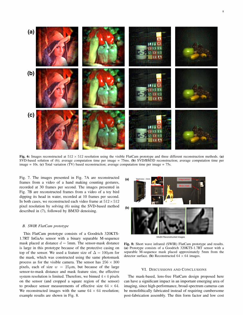
reconstructing static scenes in Fig. 6. We used MATLABfor solving all the computational problems. For the resultspresented in Fig. 6, we recorded sensor measurements whiledisplaying test images on an LCD monitor placed 28cm awayfrom the camera and by placing various objects in front of thecamera in ambient lighting.
We used three methods for reconstructing the scenes fromthe sensor measurements:
1) We computed and stored the SVD of ΦL,ΦR and solvedthe `2-regularized problem in (6) as described in (7).The average computation time for the reconstruction of asingle 512× 512 image on a standard laptop was 75ms.The results of SVD-based reconstruction are presented inFig. 6B. The reconstructed images are slightly noisy, withdetails missing around the edges.
2) To reduce the noise in our SVD-estimated images, weapplied BM3D denoising to each reconstructed image.The results of SVD/BM3D reconstruction are presentedin Fig. 6C. The average computation time for BM3Ddenoising of a single image was 10s.
3) To improve our results further, we reconstructed by solv-ing the TV minimization problem (8). While, as expected,the TV method recovers more details around the edges,the overall reconstruction quality is not appreciably verydifferent from SVD-based reconstruction. The computa-tion time of TV, however, increases to 75s per image.
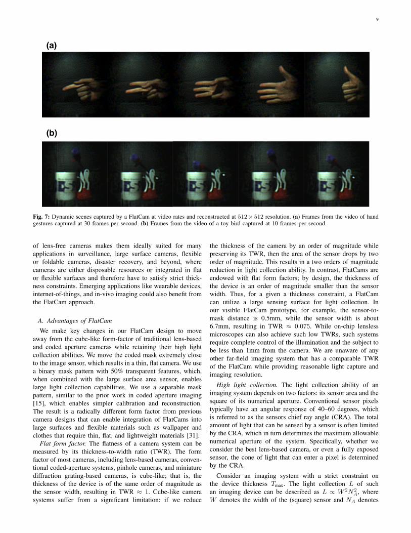
To demonstrate the flexibility of our FlatCam design, wealso captured and reconstructed dynamic scenes at typicalvideo rates. We present selected frames1 from two videos in
1Complete videos are available at http://bit.ly/FlatCam.
8
(a)!
(b)!
(c)!
Fig. 6: Images reconstructed at 512 × 512 resolution using the visible FlatCam prototype and three different reconstruction methods. (a)SVD-based solution of (6); average computation time per image = 75ms. (b) SVD/BM3D reconstruction; average computation time perimage = 10s. (c) Total variation (TV) based reconstruction; average computation time per image = 75s.
Fig. 7. The images presented in Fig. 7A are reconstructedframes from a video of a hand making counting gestures,recorded at 30 frames per second. The images presented inFig. 7B are reconstructed frames from a video of a toy birddipping its head in water, recorded at 10 frames per second.In both cases, we reconstructed each video frame at 512×512pixel resolution by solving (6) using the SVD-based methoddescribed in (7), followed by BM3D denoising.
B. SWIR FlatCam prototype
This FlatCam prototype consists of a Goodrich 320KTS-1.7RT InGaAs sensor with a binary separable M-sequencemask placed at distance d = 5mm. The sensor-mask distanceis large in this prototype because of the protective casing ontop of the sensor. We used a feature size of ∆ = 100µm forthe mask, which was constructed using the same photomaskprocess as for the visible camera. The sensor has 256 × 300pixels, each of size w = 25µm, but because of the largesensor-to-mask distance and mask feature size, the effectivesystem resolution is limited. Therefore, we binned 4×4 pixelson the sensor (and cropped a square region of the sensor)to produce sensor measurements of effective size 64 × 64.We reconstructed images with the same 64 × 64 resolution;example results are shown in Fig. 8.
(a)!
Binary mask!
Image sensor!Thickness ~ 5mm!
(b)!
64x64 Reconstructed images!
Fig. 8: Short wave infrared (SWIR) FlatCam prototype and results.(a) Prototype consists of a Goodrich 320KTS-1.7RT sensor with aseparable M-sequence mask placed approximately 5mm from thedetector surface. (b) Reconstructed 64 × 64 images.
VI. DISCUSSIONS AND CONCLUSIONS
The mask-based, lens-free FlatCam design proposed herecan have a significant impact in an important emerging area ofimaging, since high-performance, broad-spectrum cameras canbe monolithically fabricated instead of requiring cumbersomepost-fabrication assembly. The thin form factor and low cost
9
(a)!
(b)!
Fig. 7: Dynamic scenes captured by a FlatCam at video rates and reconstructed at 512× 512 resolution. (a) Frames from the video of handgestures captured at 30 frames per second. (b) Frames from the video of a toy bird captured at 10 frames per second.
of lens-free cameras makes them ideally suited for manyapplications in surveillance, large surface cameras, flexibleor foldable cameras, disaster recovery, and beyond, wherecameras are either disposable resources or integrated in flator flexible surfaces and therefore have to satisfy strict thick-ness constraints. Emerging applications like wearable devices,internet-of-things, and in-vivo imaging could also benefit fromthe FlatCam approach.
A. Advantages of FlatCam
We make key changes in our FlatCam design to moveaway from the cube-like form-factor of traditional lens-basedand coded aperture cameras while retaining their high lightcollection abilities. We move the coded mask extremely closeto the image sensor, which results in a thin, flat camera. We usea binary mask pattern with 50% transparent features, which,when combined with the large surface area sensor, enableslarge light collection capabilities. We use a separable maskpattern, similar to the prior work in coded aperture imaging[15], which enables simpler calibration and reconstruction.The result is a radically different form factor from previouscamera designs that can enable integration of FlatCams intolarge surfaces and flexible materials such as wallpaper andclothes that require thin, flat, and lightweight materials [31].
Flat form factor. The flatness of a camera system can bemeasured by its thickness-to-width ratio (TWR). The formfactor of most cameras, including lens-based cameras, conven-tional coded-aperture systems, pinhole cameras, and miniaturediffraction grating-based cameras, is cube-like; that is, thethickness of the device is of the same order of magnitude asthe sensor width, resulting in TWR ≈ 1. Cube-like camerasystems suffer from a significant limitation: if we reduce
the thickness of the camera by an order of magnitude whilepreserving its TWR, then the area of the sensor drops by twoorder of magnitude. This results in a two orders of magnitudereduction in light collection ability. In contrast, FlatCams areendowed with flat form factors; by design, the thickness ofthe device is an order of magnitude smaller than the sensorwidth. Thus, for a given a thickness constraint, a FlatCamcan utilize a large sensing surface for light collection. Inour visible FlatCam prototype, for example, the sensor-to-mask distance is 0.5mm, while the sensor width is about6.7mm, resulting in TWR ≈ 0.075. While on-chip lenslessmicroscopes can also achieve such low TWRs, such systemsrequire complete control of the illumination and the subject tobe less than 1mm from the camera. We are unaware of anyother far-field imaging system that has a comparable TWRof the FlatCam while providing reasonable light capture andimaging resolution.
High light collection. The light collection ability of animaging system depends on two factors: its sensor area and thesquare of its numerical aperture. Conventional sensor pixelstypically have an angular response of 40–60 degrees, whichis referred to as the sensors chief ray angle (CRA). The totalamount of light that can be sensed by a sensor is often limitedby the CRA, which in turn determines the maximum allowablenumerical aperture of the system. Specifically, whether weconsider the best lens-based camera, or even a fully exposedsensor, the cone of light that can enter a pixel is determinedby the CRA.
Consider an imaging system with a strict constraint onthe device thickness Tmax. The light collection L of suchan imaging device can be described as L ∝ W 2N2
A, whereW denotes the width of the (square) sensor and NA denotes
10
the numerical aperture. Since Wmax = Tmax/TWR, we haveL ∝ W 2N2
A ≤ (NATmax/TWR)2. Thus, given a thicknessconstraint Tmax, the light collection of an imaging system isdirectly proportional to the square of the numerical apertureand inversely proportional to the square of its TWR. Thus,smaller TWR leads to better light collection.
The numerical aperture of our prototype FlatCams is limitedby the CRA of the sensors. Moreover, half of the features inour mask are opaque and block one half of the light that wouldhave otherwise entered the sensor. Realizing that the numericalaperture of such a FlatCam is reduced only by a factor of
√2
compared to an open aperture, yet its TWR is reduced by anorder of magnitude leads to the conclusion that a FlatCamcollects approximately two orders of magnitude more lightthan a cube-like miniature camera of the same thickness.
B. Limitations of FlatCam
FlatCam is a radical departure from centuries of researchand development in lens-based cameras, and as such thisradical departure has its own limitations.
Achievable image/angular resolution. Our current proto-types have low spatial resolution which is attributed to twofactors. First, it is well known that angular resolution ofpinhole cameras and coded aperture cameras decreases whenthe mask is moved closer to the sensor [6]. This resultsin an implicit tradeoff between the achievable thickness andthe achievable resolution. Second, the image recorded on theimage sensor in a FlatCam is a linear combination of thescene radiance, where the multiplexing matrix is controlled bythe mask pattern and distance between mask and sensor. Thismeans that recovering the scene from sensor measurementsrequires demultiplexing. Noise amplification is an unfortunateoutcome of any linear demultiplexing based system. Whilethe magnitude of this noise amplification can be controlled bycareful design of the mask patterns, they cannot be completelyeliminated in FlatCam. In addition, the singular values of thelinear system are such that the noise amplification for higherspatial frequencies is larger, which consequently limits thespatial resolution of the recovered image. We are currentlyworking on several techniques to improve the spatial resolutionof the recovered images.
Direct-view and real-time operation. In traditional lens-based cameras, the image sensed by the image sensor isthe photograph of the scene. In FlatCam, a computationalalgorithm is required to convert the sensor measurementsinto a photograph of the scene. This results in a time-lagbetween the sensor acquisition and the image display, a time-lag that depends on processing time. Currently, our SVD-based reconstruction operates at near real-time (about 10 fps)resulting in about a 100 ms delay between capture and display.While this may be acceptable for certain applications, thereare many other applications such as augmented reality andvirtual reality, where such delays are unacceptable. Orderof magnitude improvements in processing times are requiredbefore FlatCam becomes amenable to such applications.
ACKNOWLEDGMENTS
This work was supported by NSF grants IIS–1116718,CCF–1117939, and CCF–1527501.
REFERENCES
[1] R. Dicke, “Scatter-hole cameras for x-rays and gamma rays,” TheAstrophysical Journal, vol. 153, p. L101, 1968.
[2] E. Fenimore and T. Cannon, “Coded aperture imaging with uniformlyredundant arrays,” Applied optics, vol. 17, no. 3, pp. 337–347, 1978.
[3] T. Cannon and E. Fenimore, “Coded aperture imaging: Many holes makelight work,” Optical Engineering, vol. 19, no. 3, pp. 193–283, 1980.
[4] P. Durrant, M. Dallimore, I. Jupp, and D. Ramsden, “The applicationof pinhole and coded aperture imaging in the nuclear environment,”Nuclear Instruments and Methods in Physics Research Section A:Accelerators, Spectrometers, Detectors and Associated Equipment, vol.422, no. 1, pp. 667–671, 1999.
[5] V. Dragoi, A. Filbert, S. Zhu, and G. Mittendorfer, “Cmos wafer bondingfor back-side illuminated image sensors fabrication,” in 2010 11thInternational Conference on Electronic Packaging Technology & HighDensity Packaging, 2010, pp. 27–30.
[6] D. J. Brady, Optical imaging and spectroscopy. John Wiley & Sons,2009.
[7] E. J. Candes, J. K. Romberg, and T. Tao, “Stable signal recovery fromincomplete and inaccurate measurements,” Communications on pure andapplied mathematics, vol. 59, no. 8, pp. 1207–1223, 2006.
[8] D. L. Donoho, “Compressed sensing,” IEEE Transactions on Informa-tion Theory, vol. 52, no. 4, pp. 1289–1306, 2006.
[9] R. G. Baraniuk, “Compressive sensing,” IEEE signal processing maga-zine, vol. 24, no. 4, 2007.
[10] R. F. Marcia and R. M. Willett, “Compressive coded aperture super-resolution image reconstruction,” in IEEE International Conference onAcoustics, Speech and Signal Processing (ICASSP), 2008, pp. 833–836.
[11] A. Wagadarikar, R. John, R. Willett, and D. Brady, “Single disperserdesign for coded aperture snapshot spectral imaging,” Applied optics,vol. 47, no. 10, pp. B44–B51, 2008.
[12] P. Llull, X. Liao, X. Yuan, J. Yang, D. Kittle, L. Carin, G. Sapiro, andD. J. Brady, “Coded aperture compressive temporal imaging,” Opticsexpress, vol. 21, no. 9, pp. 10 526–10 545, 2013.
[13] A. Zomet and S. K. Nayar, “Lensless imaging with a controllableaperture,” in IEEE Computer Society Conference on Computer Visionand Pattern Recognition, vol. 1, 2006, pp. 339–346.
[14] G. Huang, H. Jiang, K. Matthews, and P. Wilford, “Lensless imaging bycompressive sensing,” in 20th IEEE International Conference on ImageProcessing, 2013, pp. 2101–2105.
[15] M. J. DeWeert and B. P. Farm, “Lensless coded-aperture imaging withseparable doubly-toeplitz masks,” Optical Engineering, vol. 54, no. 2,pp. 023 102–023 102, 2015.
[16] J. Tanida, T. Kumagai, K. Yamada, S. Miyatake, K. Ishida, T. Morimoto,N. Kondou, D. Miyazaki, and Y. Ichioka, “Thin observation module bybound optics (TOMBO): concept and experimental verification,” Appliedoptics, vol. 40, no. 11, pp. 1806–1813, 2001.
[17] M. Shankar, R. Willett, N. Pitsianis, T. Schulz, R. Gibbons, R. Te Kolste,J. Carriere, C. Chen, D. Prather, and D. Brady, “Thin infrared imagingsystems through multichannel sampling,” Applied optics, vol. 47, no. 10,pp. B1–B10, 2008.
[18] A. Bruckner, J. Duparre, R. Leitel, P. Dannberg, A. Brauer, andA. Tunnermann, “Thin wafer-level camera lenses inspired by insectcompound eyes,” Optics Express, vol. 18, no. 24, pp. 24 379–24 394,2010.
[19] K. Venkataraman, D. Lelescu, J. Duparre, A. McMahon, G. Molina,P. Chatterjee, R. Mullis, and S. Nayar, “Picam: An ultra-thin highperformance monolithic camera array,” ACM Transactions on Graphics(TOG), vol. 32, no. 6, p. 166, 2013.
[20] E. J. Tremblay, R. A. Stack, R. L. Morrison, and J. E. Ford, “Ultrathincameras using annular folded optics,” Applied optics, vol. 46, no. 4, pp.463–471, 2007.
[21] A. Wang, P. Gill, and A. Molnar, “Angle sensitive pixels in cmos forlensless 3d imaging,” in IEEE Custom Integrated Circuits Conference,2009, pp. 371–374.
[22] P. R. Gill, C. Lee, D.-G. Lee, A. Wang, and A. Molnar, “A mi-croscale camera using direct fourier-domain scene capture,” Opticsletters, vol. 36, no. 15, pp. 2949–2951, 2011.
[23] P. R. Gill and D. G. Stork, “Lensless ultra-miniature imagers using odd-symmetry spiral phase gratings,” in Computational Optical Sensing andImaging. Optical Society of America, 2013, pp. CW4C–3.

11
[24] D. Stork and P. Gill, “Lensless ultra-miniature cmos computational im-agers and sensors,” in International Conference on Sensor Technologiesand Applications, 2013, pp. 186–190.
[25] A. Greenbaum, W. Luo, T.-W. Su, Z. Gorocs, L. Xue, S. O. Isik-man, A. F. Coskun, O. Mudanyali, and A. Ozcan, “Imaging withoutlenses: Achievements and remaining challenges of wide-field on-chipmicroscopy,” Nature methods, vol. 9, no. 9, pp. 889–895, 2012.
[26] A. Greenbaum, Y. Zhang, A. Feizi, P.-L. Chung, W. Luo, S. R.Kandukuri, and A. Ozcan, “Wide-field computational imaging of pathol-ogy slides using lens-free on-chip microscopy,” Science translationalmedicine, vol. 6, no. 267, pp. 267ra175–267ra175, 2014.
[27] S. W. Golomb, Shift register sequences. Aegean Park Press, 1982.[28] S. Mallat, A wavelet tour of signal processing: the sparse way. Aca-
demic press, 2008.[29] L. I. Rudin, S. Osher, and E. Fatemi, “Nonlinear total variation based
noise removal algorithms,” Physica D: Nonlinear Phenomena, vol. 60,no. 1, pp. 259–268, 1992.
[30] K. Dabov, A. Foi, V. Katkovnik, and K. Egiazarian, “Image denoising bysparse 3-d transform-domain collaborative filtering,” IEEE Transactionson Image Processing, vol. 16, no. 8, pp. 2080–2095, 2007.
[31] F. Koppens, T. Mueller, P. Avouris, A. Ferrari, M. Vitiello, and M. Polini,“Photodetectors based on graphene, other two-dimensional materials andhybrid systems,” Nature nanotechnology, vol. 9, no. 10, pp. 780–793,2014.