flange work - norskoljeoggass.no table*. 2. necessary tools are available for splitting and ... is...
TRANSCRIPT
HandbookDecember 2017/Rev. 05
Copyright © 2012 Norwegian Oil and Gas
Design: Mintra AS
FLANGE WORK

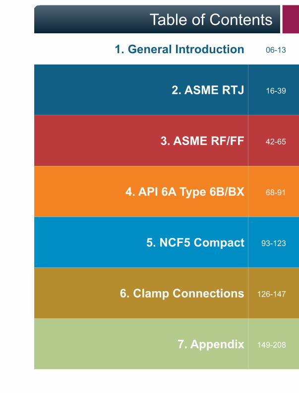
Table of Contents
1General Introduction
2. ASME RTJ
1. General Introduction
3. ASME RF/FF
4. API 6A Type 6B/BX
5. NCF5 Compact
6. Clamp Connections
7. Appendix
16-39
06-13
42-65
68-91
93-123
126-147
149-208

1 General Introduction
6 Flange Work Handbook
1.1 Background
Norwegian Oil and Gas has developed a handbook for working on flanged connections on hydrocarbon systems. The handbook can be downloaded from www.norskoljeoggass.no.
The handbook covers typical flanges and gaskets that are used in the petroleum industry and includes disassembly, inspection, alignment, installation and verification of flanges. The handbook is the basis for a training curriculum for flanges on hydrocarbon systems. The training curriculum can also be downloaded from www.norskoljeoggass.no.

1General Introduction
Flange Work Handbook 7
1 General Introduction
8 Flange Work Handbook
1. Always maintain a good overview of the work siteand who is involved in the work.
2. Do not use solutions that can harm people ortools.
3. Use proper personal safety equipment such assafety shoes, protective gloves, goggles, etc.
4. Hoses and connectors that are damaged maynot be used.
5. To prevent the danger of pinching when usinghydraulic torque tools, maintain a safe distancefrom reaction surfaces and the tool’s counterholdduring operation.
6. If there is no tool attached by itself to the nut/bolt, it should be secured so that it doesn’t fall offduring the operation.
7. Check that there is an approved and signed workpermit for the job before starting.
8. Cordon off the area before the job starts withapproved cordoning bands.
9. When working at heights, the working area mustbe secured against falling objects (tools, bolts,gaskets, etc.).
1.2 HSE Precautions
1General Introduction
Flange Work Handbook 9
Normally, the following should be included in a work package:
1. Marked P&ID or ISO for each connection(pipe flange or valve connection) that shall bedisassembled/assembled.
2. Bolting table.
3. Work description.
4. Material list.
5. Activity and inspection schedule.
6. Valve and lockout lists should be preparedand isolation/closure for engagement with theprocess equipment.
1.3 Checklist for the Work Package
1 General Introduction
10 Flange Work Handbook
The responsible planner for the job shall ensure that:
1. The correct gaskets or sealing rings areavailable, refer to pipe and valve specification orbolting table*.
2. Necessary tools are available for splitting andassembly of the relevant connections.
3. Necessary lifting equipment and jigs areavailable. Check the need for scaffolds andcordons for working at heights.
4. Necessary calibrated tools for bolt tightening andapproved lubricants for bolts are available.
5. History of any problems with previous attachmentof the connection are checked, and that relevantsteps are planned.
*For transitions between different materials or pressure ratings, select a gasketfor the most delicate material and the highest pressure. Use the lowest moment(it will be the moment for the weakest material) from the two relevant boltingtables when tightening.
1.3 Checklist for the Work Package
1General Introduction
Flange Work Handbook 11
The person responsible for the execution (mechanic) and the equipment owner/system supervisor operator/process technician/area supervisor operator shall ensure that all valves that shall be operated on are labeled with label sheets.
Before opening/splitting equipment that is normally pressurized, the operational system supervisor (operator) and the executing mechanic shall personally ensure:
1. That there is an approved work permit.
2. That SJA (Safe Job Analysis and any pre-jobconversation) is done if it is required.
3. That they are at the correct connection.
4. That isolation/lockout is correctly done andthe system is depressurized and free ofhydrocarbons.
5. That valves that shall be disassembled are inthe half-open position, or as shown in the valve’smaintenance handbook, so that the valve is freeof pockets with enclosed pressure.
6. That the pipe hangers or pipe support areunloaded; this applies both to spring-loaded andfixed pipe hangers/pipe supports. Where thereis a danger of tension in the pipe, initiate safetymeasures.
1.4 Execution
1 General Introduction
12 Flange Work Handbook
7. That the relevant insulation is removed and heatcables are disconnected.
8. The executing mechanic should review themanufacturer’s user manual for the tool to beused on the job.
9. The executing mechanic should review themanufacturer’s user manual for the tool to beused on the job.
10. Check that the pipe/equipment is securedagainst unanticipated shifting since this canoccur during splitting of a flange.
1.4 Execution

1
Flange Work Handbook 13
Notes

2ASME RTJ

2ASME RTJ
2.1 Flange and Gasket 16-17
2.2 Disassembly 18-23
2.3 Inspection 24-25
2.4 Alignment 26-28
2.5 Assembly 29-35
2.6 Follow-up Inspection 36-39
2 ASME RTJ
16 Flange Work Handbook
AS
ME
RTJ
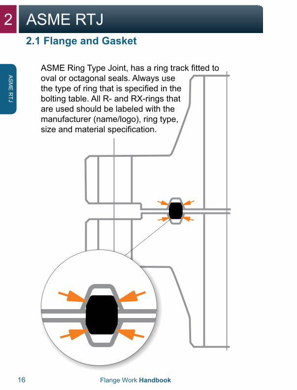
ASME Ring Type Joint, has a ring track fitted to oval or octagonal seals. Always use the type of ring that is specified in the bolting table. All R- and RX-rings that are used should be labeled with the manufacturer (name/logo), ring type, size and material specification.
2.1 Flange and Gasket
2ASME RTJ
Flange Work Handbook 17
AS
ME
RTJ
2.1 Flange and Gasket
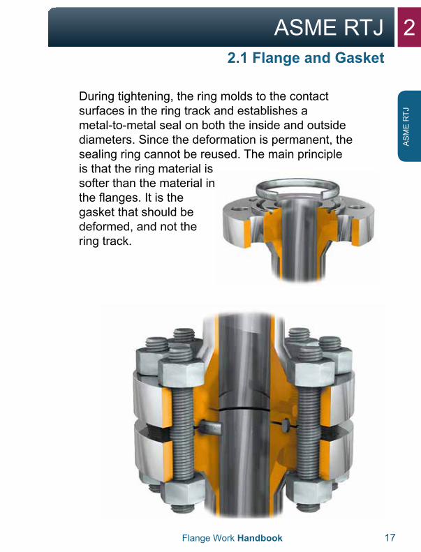
During tightening, the ring molds to the contact surfaces in the ring track and establishes a metal-to-metal seal on both the inside and outside diameters. Since the deformation is permanent, the sealing ring cannot be reused. The main principle is that the ring material is softer than the material in the flanges. It is the gasket that should be deformed, and not the ring track.
2 ASME RTJ
18 Flange Work Handbook
AS
ME
RTJ
2.2.1 Phase 1 (loosen bolts)
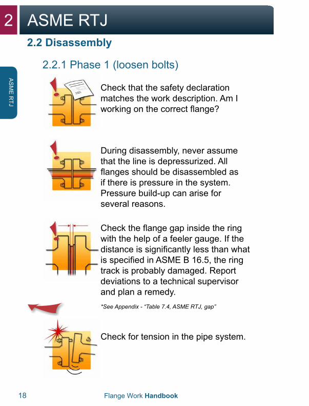
Check that the safety declaration matches the work description. Am I working on the correct flange?
During disassembly, never assume that the line is depressurized. All flanges should be disassembled as if there is pressure in the system. Pressure build-up can arise for several reasons.
Check the flange gap inside the ring with the help of a feeler gauge. If the distance is significantly less than what is specified in ASME B 16.5, the ring track is probably damaged. Report deviations to a technical supervisor and plan a remedy.*See Appendix - “Table 7.4, ASME RTJ, gap”
Check for tension in the pipe system.
2.2 Disassembly
2ASME RTJ
Flange Work Handbook 19
AS
ME
RTJ
2.2.1 Phase 1 (loosen bolts)
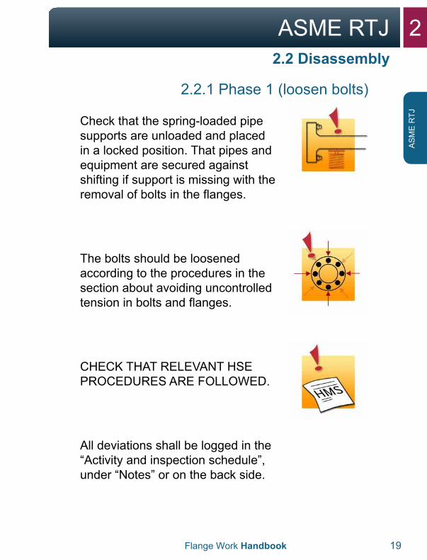
Check that the spring-loaded pipe supports are unloaded and placed in a locked position. That pipes and equipment are secured against shifting if support is missing with the removal of bolts in the flanges.
The bolts should be loosened according to the procedures in the section about avoiding uncontrolled tension in bolts and flanges.
CHECK THAT RELEVANT HSE PROCEDURES ARE FOLLOWED.
All deviations shall be logged in the “Activity and inspection schedule”, under “Notes” or on the back side.
2.2 Disassembly
2 ASME RTJ
20 Flange Work Handbook
AS
ME
RTJ
2.2.1 Phase 1 (loosen bolts)
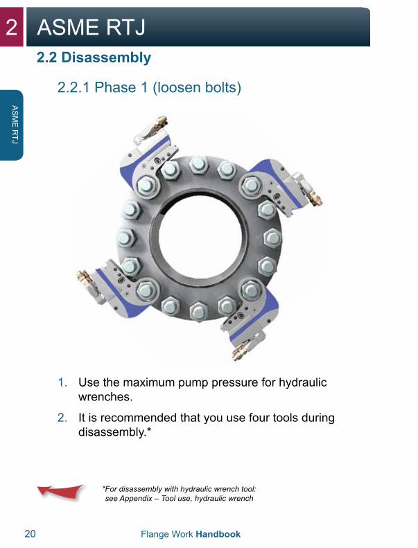
1. Use the maximum pump pressure for hydraulicwrenches.
2. It is recommended that you use four tools duringdisassembly.*
* For disassembly with hydraulic wrench tool:see Appendix – Tool use, hydraulic wrench
2.2 Disassembly
2ASME RTJ
Flange Work Handbook 21
AS
ME
RTJ
2.2.1 Phase 1 (loosen bolts)
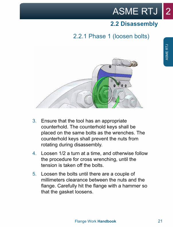
3. Ensure that the tool has an appropriatecounterhold. The counterhold keys shall beplaced on the same bolts as the wrenches. Thecounterhold keys shall prevent the nuts fromrotating during disassembly.
4. Loosen 1/2 a turn at a time, and otherwise followthe procedure for cross wrenching, until thetension is taken off the bolts.
5. Loosen the bolts until there are a couple ofmillimeters clearance between the nuts and theflange. Carefully hit the flange with a hammer sothat the gasket loosens.
2.2 Disassembly
2 ASME RTJ
22 Flange Work Handbook
AS
ME
RTJ
2.2.2 Phase 2 (open flange)
2.2 Disassembly
WARNING:With use of a hydraulic spreader, it is important to remember the following:
• If there is one or more bolts stuck in theflange’s bolt hole, this can mean that there istension in the pipe system. In that case, greatcare should be taken in further disassembly ofthe flange, and potentially securing the pipeshould be considered.
• Contact a technical supervisor if there is doubtor a need for action.
WARNING:With use of a hydraulic spreader, it is important to remember the following:
• Never stick fingers between the flanges beforea safety block is installed and the spreadersare unloaded.
• Use the handle on the spreader when takingout or moving the tool.
2ASME RTJ
Flange Work Handbook 23
AS
ME
RTJ
2.2.2 Phase 2 (open flange)
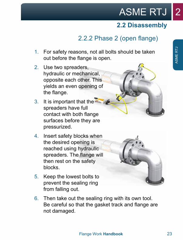
1. For safety reasons, not all bolts should be takenout before the flange is open.
2. Use two spreaders,hydraulic or mechanical,opposite each other. Thisyields an even opening ofthe flange.
3. It is important that thespreaders have fullcontact with both flangesurfaces before they arepressurized.
4. Insert safety blocks whenthe desired opening isreached using hydraulicspreaders. The flange willthen rest on the safetyblocks.
5. Keep the lowest bolts toprevent the sealing ringfrom falling out.
6. Then take out the sealing ring with its own tool.Be careful so that the gasket track and flange arenot damaged.
2.2 Disassembly
2 ASME RTJ
24 Flange Work Handbook
AS
ME
RTJ
2.3 Inspection
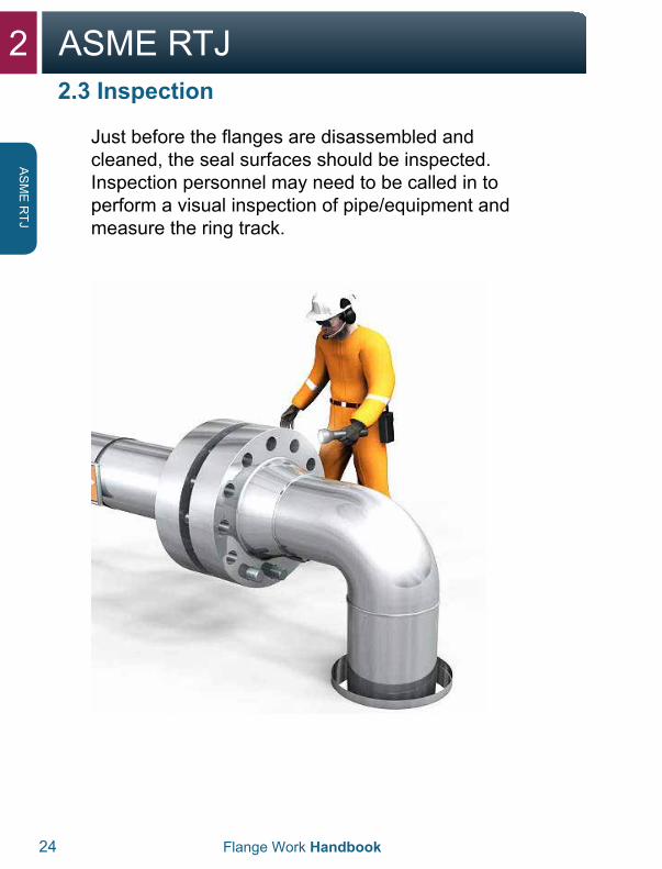
Just before the flanges are disassembled and cleaned, the seal surfaces should be inspected. Inspection personnel may need to be called in to perform a visual inspection of pipe/equipment and measure the ring track.
2ASME RTJ
Flange Work Handbook 25
AS
ME
RTJ
If there is damage, this should be reported to a technical supervisor. Any tension in the pipe system shall also be reported to a technical supervisor. Bolts and nuts should be checked for damage and the threads should be cleaned. Normally, galvanized bolts should not be reused.
1. The surface roughness of the inclined surfaces inthe ring track should be checked visually againstthe RA standard (should have a reference pointfor roughness measurement).
2. The surface roughness should not exceed1.6 micrometers (μm).
For more information about inspection and repair of flanges, refer to API 574 and ASME PCC-2-2011 article 3.5.
2.3 Inspection
If the flanges are not assembled immediately, the gasket surface should be protected.
2 ASME RTJ
26 Flange Work Handbook
AS
ME
RTJ
2.4.1 Skewed connection
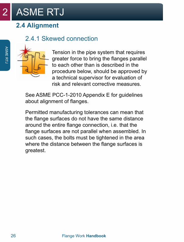
Tension in the pipe system that requires greater force to bring the flanges parallel to each other than is described in the procedure below, should be approved by a technical supervisor for evaluation of risk and relevant corrective measures.
See ASME PCC-1-2010 Appendix E for guidelines about alignment of flanges.
Permitted manufacturing tolerances can mean that the flange surfaces do not have the same distance around the entire flange connection, i.e. that the flange surfaces are not parallel when assembled. In such cases, the bolts must be tightened in the area where the distance between the flange surfaces is greatest.
2.4 Alignment
2ASME RTJ
Flange Work Handbook 27
AS
ME
RTJ
2.4 Alignment
2.4.1 Skewed connection
1. The object with dealing with skews is to find outwhere the flanges have the largest gap.
2. Insert all the bolts in the flange connection.
3. With alignment of the flange connection, no morethan half of the number of bolts in the flangeconnection should be used, and neighboringbolts shall not be used so that there is alwaysat least one unused bolt between bolts that areused for alignment.
4. Tighten any bolt in the area where the gapbetween the flange surfaces is greatest, with40% of the given moment for a torque tool, or40% of the B-pressure for a wrench tool. Usethe lowest possible number of bolts to align theflanges.
5. The object when dealing with skews is to goaround the entire flange connection severaltimes during the process until the flanges areparallel.
2 ASME RTJ
28 Flange Work Handbook
AS
ME
RTJ
2.4 Alignment
2.4.2 Parallel shifts
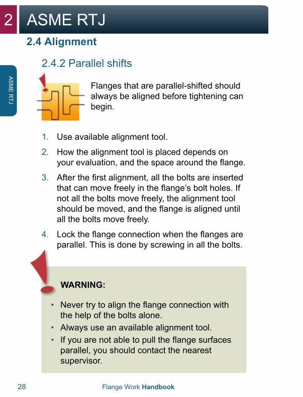
Flanges that are parallel-shifted should always be aligned before tightening can begin.
1. Use available alignment tool.
2. How the alignment tool is placed depends onyour evaluation, and the space around the flange.
3. After the first alignment, all the bolts are insertedthat can move freely in the flange’s bolt holes. Ifnot all the bolts move freely, the alignment toolshould be moved, and the flange is aligned untilall the bolts move freely.
4. Lock the flange connection when the flanges areparallel. This is done by screwing in all the bolts.
WARNING:
• Never try to align the flange connection withthe help of the bolts alone.
• Always use an available alignment tool.• If you are not able to pull the flange surfaces
parallel, you should contact the nearestsupervisor.
2ASME RTJ
Flange Work Handbook 29
AS
ME
RTJ
2.5 Assembly
Before tightening flanges, be sure to thoroughly plan and prepare for the job in advance.
1. Flange and seal surfaces should be checkedfor damage, corrosion and wear, and that thering track is free of coatings from paint andpreservative. There should not be any paint onthe flange surfaces on any side of the ring track.
2. The flange’s contact surface against the nutsshould also be free of any thick layer of paintand preservative, which can cause bolts to failto tighten after assembly. Only primer can beaccepted under the contact surfaces of the nut.
3. Clean seal surfaces. Steel brushes or approvedemery paper may be used for this. Approvedsolvents and cloths may be used for finalcleaning.
4. Clean along the ring track. Ensure that thecleaning doesn’t create radial tracks in the sealsurface. It is especially important to removeimperfections in a radial direction.
2 ASME RTJ
30 Flange Work Handbook
AS
ME
RTJ
2.5 Assembly
2.5.1 Sealing ring
For ASME RTJ, octagonal or oval metal rings may be used. The type of ring to be used is specified in the bolting chart/pipe specification.
1. Opening between the flanges should be largerthan the thickness of the sealing ring so that thisis not damaged during assembly.
2. A new sealing ring should always be insertedwhen sealing flanges that have been opened.
3. Check that you have the correct sealing ringaccording to the table and that it is free ofdamage. The ring’s size and material quality ismarked on the ring.
4. Rings with incomplete markings should not beused.
5. Insert the lowest bolts in the flange connectionso that the sealing ring doesn’t fall out.
6. Check that the ring sits correctly. It should beable to “rock” in the ring track.
Metal rings (RTJ) should be lubricated with a thin layer of acid-free Vaseline or a thin machine oil before you insert them so that point loads are avoided and so that it is easier to disassemble/remove the gasket again. Gaskets that are coated with PTFE should not be lubricated.
Grease or similar substances should not be used in the ring track, since this can prevent the ring from reaching full tightness.
2ASME RTJ
Flange Work Handbook 31
AS
ME
RTJ
2.5 Assembly
2.5.2 Bolts
The bolt’s labeling is stamped on the one end of the bolt.
The bolting chart provides information about the bolts, the type of bolt and nut material, and any washers that should be used.
It includes a list of tools (for bolt diameters over 1"), number of bolts, bolt diameter, bolt length, key width, tightening force, the torque moment that the bolt should be tightened with, or A and B pressure if a hydraulic wrench equipment will be used.
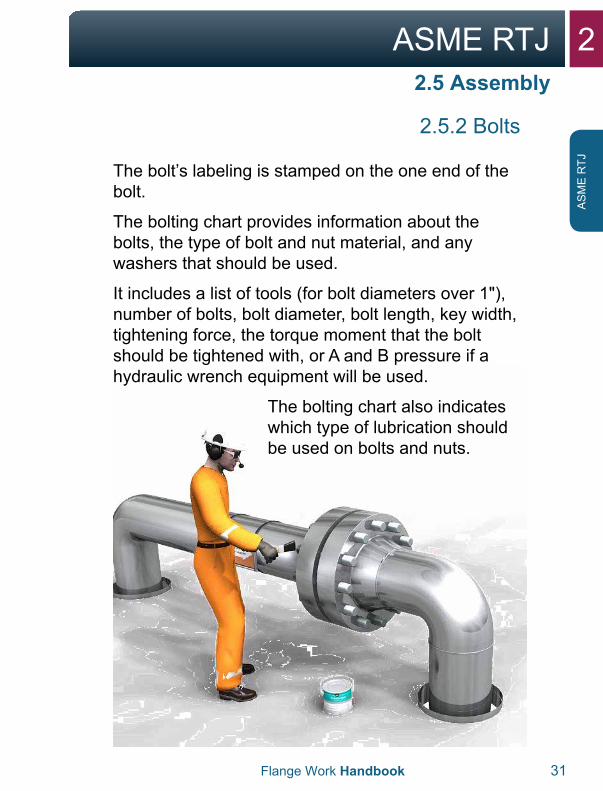
The bolting chart also indicates which type of lubrication should be used on bolts and nuts.
2 ASME RTJ
32 Flange Work Handbook
AS
ME
RTJ
2.5 Assembly
2.5.2 Bolts
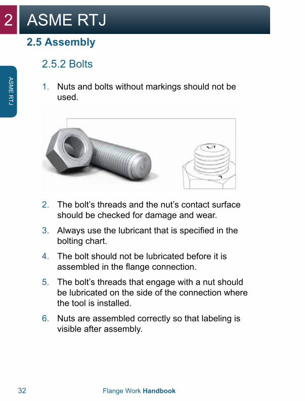
1. Nuts and bolts without markings should not beused.
2. The bolt’s threads and the nut’s contact surfaceshould be checked for damage and wear.
3. Always use the lubricant that is specified in thebolting chart.
4. The bolt should not be lubricated before it isassembled in the flange connection.
5. The bolt’s threads that engage with a nut shouldbe lubricated on the side of the connection wherethe tool is installed.
6. Nuts are assembled correctly so that labeling isvisible after assembly.
2ASME RTJ
Flange Work Handbook 33
AS
ME
RTJ
2.5.2 Bolts
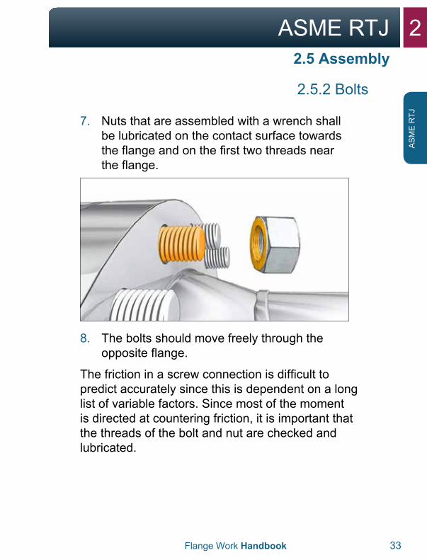
7. Nuts that are assembled with a wrench shallbe lubricated on the contact surface towardsthe flange and on the first two threads nearthe flange.
8. The bolts should move freely through theopposite flange.
The friction in a screw connection is difficult to predict accurately since this is dependent on a long list of variable factors. Since most of the moment is directed at countering friction, it is important that the threads of the bolt and nut are checked and lubricated.
2.5 Assembly
2 ASME RTJ
34 Flange Work Handbook
AS
ME
RTJ
2.5 Assembly
2.5.3 Tightening
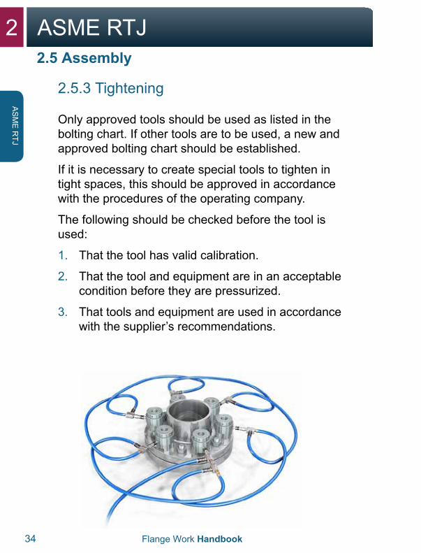
Only approved tools should be used as listed in the bolting chart. If other tools are to be used, a new and approved bolting chart should be established.
If it is necessary to create special tools to tighten in tight spaces, this should be approved in accordance with the procedures of the operating company.
The following should be checked before the tool is used:
1. That the tool has valid calibration.
2. That the tool and equipment are in an acceptablecondition before they are pressurized.
3. That tools and equipment are used in accordancewith the supplier’s recommendations.
2ASME RTJ
Flange Work Handbook 35
AS
ME
RTJ
2.5 Assembly
2.5.3 Tightening
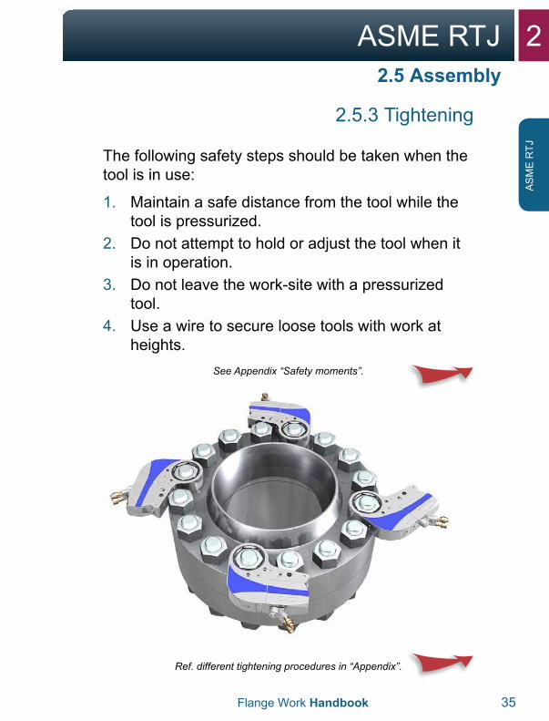
The following safety steps should be taken when the tool is in use:
1. Maintain a safe distance from the tool while thetool is pressurized.
2. Do not attempt to hold or adjust the tool when itis in operation.
3. Do not leave the work-site with a pressurizedtool.
4. Use a wire to secure loose tools with work atheights.
See Appendix “Safety moments”.
Ref. different tightening procedures in “Appendix”.
2 ASME RTJ
36 Flange Work Handbook
AS
ME
RTJ
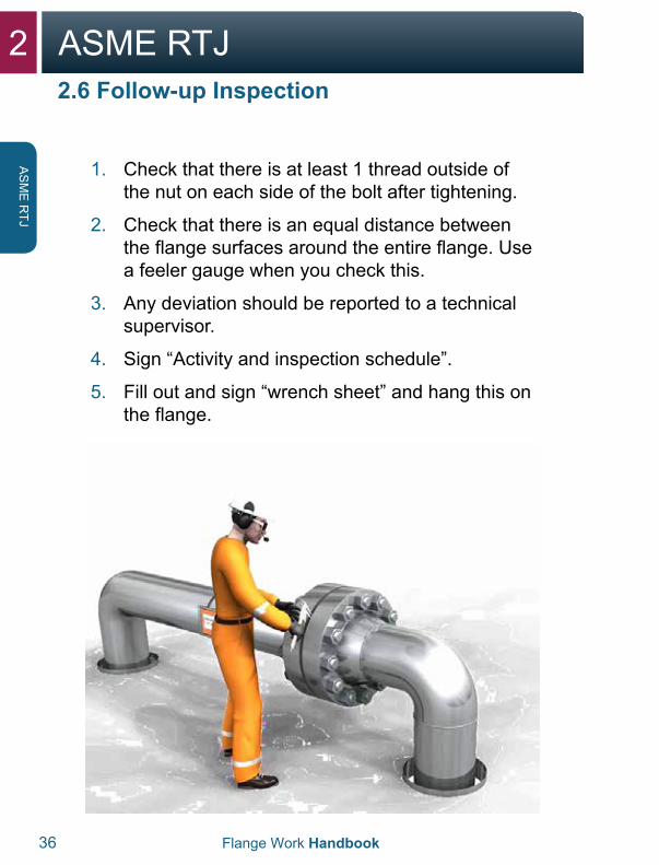
1. Check that there is at least 1 thread outside ofthe nut on each side of the bolt after tightening.
2. Check that there is an equal distance betweenthe flange surfaces around the entire flange. Usea feeler gauge when you check this.
3. Any deviation should be reported to a technicalsupervisor.
4. Sign “Activity and inspection schedule”.
5. Fill out and sign “wrench sheet” and hang this onthe flange.
2.6 Follow-up Inspection
2ASME RTJ
Flange Work Handbook 37
AS
ME
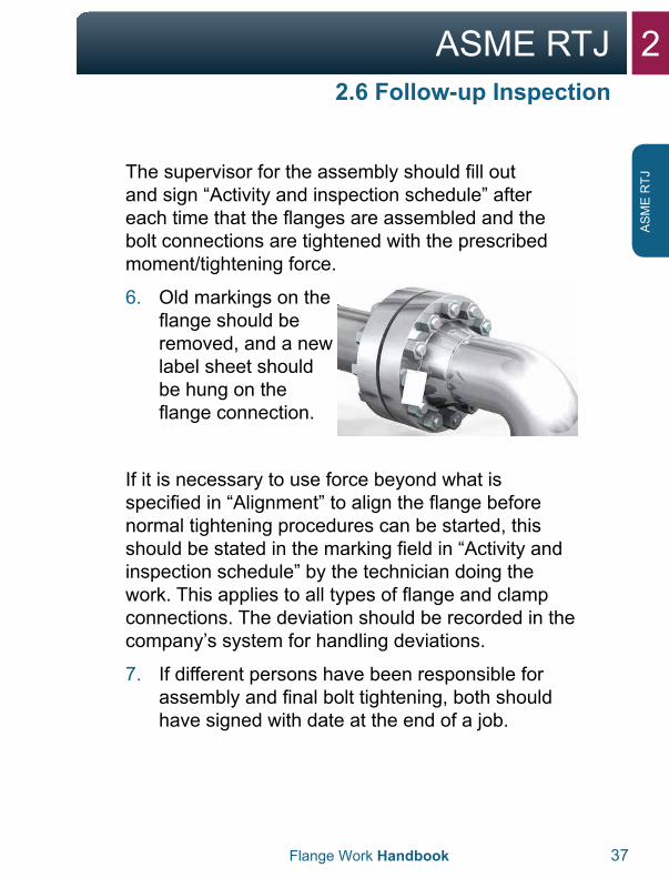
RTJThe supervisor for the assembly should fill out
and sign “Activity and inspection schedule” after each time that the flanges are assembled and the bolt connections are tightened with the prescribed moment/tightening force.
6. Old markings on theflange should beremoved, and a newlabel sheet shouldbe hung on theflange connection.
If it is necessary to use force beyond what is specified in “Alignment” to align the flange before normal tightening procedures can be started, this should be stated in the marking field in “Activity and inspection schedule” by the technician doing the work. This applies to all types of flange and clamp connections. The deviation should be recorded in the company’s system for handling deviations.
7. If different persons have been responsible forassembly and final bolt tightening, both shouldhave signed with date at the end of a job.
2.6 Follow-up Inspection
2 ASME RTJ
38 Flange Work Handbook
AS
ME
RTJ
2.6 Follow-up Inspection
Exceptions:
For non-dangerous help/support issues, the “Activity and inspection schedule”, and labeling of the flange connections may be ignored for ASME pressure ratings of 150 and 300, where the operating temperature is between 0° and 50°C.
1. If the equipment is put in operation immediately(with the technician executing and an operationalsupervisor present), the labelling of the flangeconnection and use of “Activity and inspectionschedule” can be ignored.
2. Any type of deviations should be recorded in thecompany’s system for deviation management.
2ASME RTJ
Flange Work Handbook 39
AS
ME
RTJ

3ASME RF/FF
3ASME RF/FF
3.1 Flange and Gasket 42-44
3.2 Disassembly 44-49
3.3 Inspection 50-51
3.4 Alignment 52-53
3.5 Assembly 54-61
3.6 Follow-up Inspection 62-65
3 ASME RF/FF
42 Flange Work Handbook
AS
ME
RF/FF
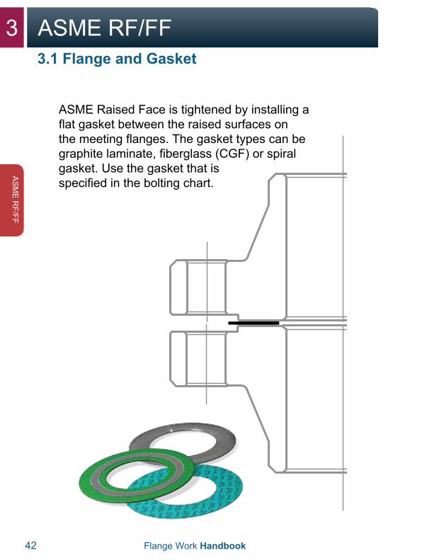
ASME Raised Face is tightened by installing a flat gasket between the raised surfaces on the meeting flanges. The gasket types can be graphite laminate, fiberglass (CGF) or spiral gasket. Use the gasket that is specified in the bolting chart.
3.1 Flange and Gasket
3ASME RF/FF
Flange Work Handbook 43
AS
ME
RF/
FF
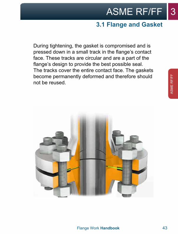
During tightening, the gasket is compromised and is pressed down in a small track in the flange’s contact face. These tracks are circular and are a part of the flange’s design to provide the best possible seal. The tracks cover the entire contact face. The gaskets become permanently deformed and therefore should not be reused.
3.1 Flange and Gasket
3 ASME RF/FF
44 Flange Work Handbook
AS
ME
RF/FF
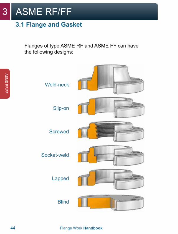
Flanges of type ASME RF and ASME FF can have the following designs:
Weld-neck
Slip-on
Screwed
Socket-weld
Lapped
Blind
3.1 Flange and Gasket
3ASME RF/FF
Flange Work Handbook 45
AS
ME
RF/
FF
3.2 Disassembly
3.2.1 Phase 1 (loosen bolts)
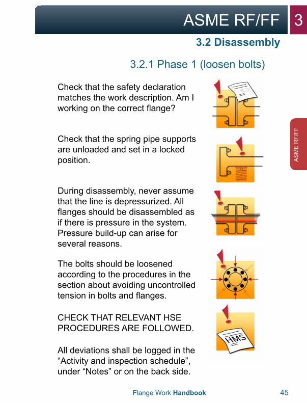
Check that the safety declaration matches the work description. Am I working on the correct flange?
Check that the spring pipe supports are unloaded and set in a locked position.
During disassembly, never assume that the line is depressurized. All flanges should be disassembled as if there is pressure in the system. Pressure build-up can arise for several reasons.
The bolts should be loosened according to the procedures in the section about avoiding uncontrolled tension in bolts and flanges.
CHECK THAT RELEVANT HSE PROCEDURES ARE FOLLOWED.
All deviations shall be logged in the “Activity and inspection schedule”, under “Notes” or on the back side.
3 ASME RF/FF
46 Flange Work Handbook
AS
ME
RF/FF
3.2 Disassembly
3.2.1 Phase 1 (loosen bolts)
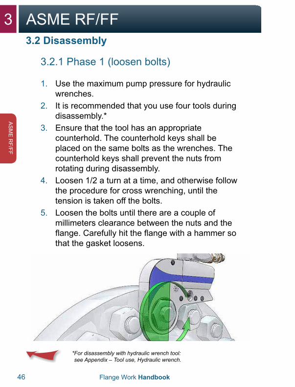
1. Use the maximum pump pressure for hydraulicwrenches.
2. It is recommended that you use four tools duringdisassembly.*
3. Ensure that the tool has an appropriatecounterhold. The counterhold keys shall beplaced on the same bolts as the wrenches. Thecounterhold keys shall prevent the nuts fromrotating during disassembly.
4. Loosen 1/2 a turn at a time, and otherwise followthe procedure for cross wrenching, until thetension is taken off the bolts.
5. Loosen the bolts until there are a couple ofmillimeters clearance between the nuts and theflange. Carefully hit the flange with a hammer sothat the gasket loosens.
* For disassembly with hydraulic wrench tool:see Appendix – Tool use, Hydraulic wrench.
3ASME RF/FF
Flange Work Handbook 47
AS
ME
RF/
FF
3.2 Disassembly
3.2.2 Phase 2 (open flange)
1. For safety reasons, not all bolts should be takenout before the flange is open.
2. Use two spreaders, hydraulic or mechanical,opposite each other. This yields an even openingof the flange.
3. It is important that the spreaders have fullcontact with both flange surfaces before they arepressurized.
4. Insert safety blocks when the desired opening isreached using hydraulic spreaders. The flangewill then rest on the safety blocks.
5. Keep the lowest bolts so that the gasket does notfall out.
6. Then remove the gasket with its own tool. Takecare that the contact surface isn’t damaged.
WARNING:With use of a hydraulic spreader, it is important to remember the following:
If there is one or more bolts stuck in the flange’s bolt hole, this can mean that there is tension in the pipe system. In that case, great care should be taken in further disassembly of the flange, and potentially securing the pipe should be considered. Contact a technical supervisor if there is doubt or a need for action.
3 ASME RF/FF
48 Flange Work Handbook
AS
ME
RF/FF
3.2 Disassembly
3.2.2 Phase 2 (open flange)
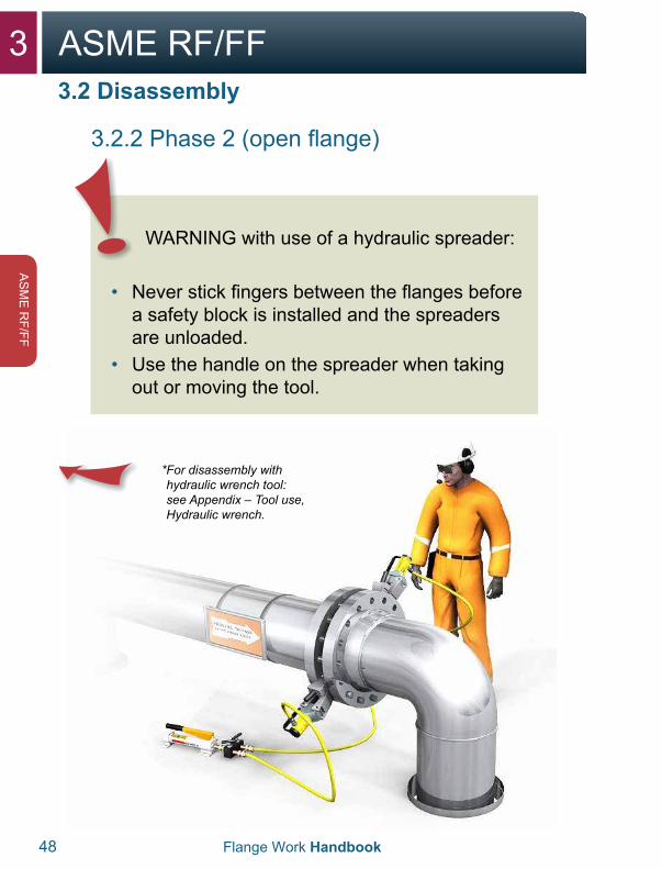
* For disassembly withhydraulic wrench tool:see Appendix – Tool use,Hydraulic wrench.
WARNING with use of a hydraulic spreader:
• Never stick fingers between the flanges beforea safety block is installed and the spreadersare unloaded.
• Use the handle on the spreader when takingout or moving the tool.
3ASME RF/FF
Flange Work Handbook 49
AS
ME
RF/
FF
3.3 Inspection
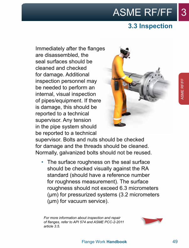
Immediately after the flanges are disassembled, the seal surfaces should be cleaned and checked for damage. Additional inspection personnel may be needed to perform an internal, visual inspection of pipes/equipment. If there is damage, this should be reported to a technical supervisor. Any tension in the pipe system should be reported to a technical supervisor. Bolts and nuts should be checked for damage and the threads should be cleaned. Normally, galvanized bolts should not be reused.
• The surface roughness on the seal surfaceshould be checked visually against the RAstandard (should have a reference numberfor roughness measurement). The surfaceroughness should not exceed 6.3 micrometers(μm) for pressurized systems (3.2 micrometers(μm) for vacuum service).
For more information about inspection and repair of flanges, refer to API 574 and ASME PCC-2-2011 article 3.5.
3 ASME RF/FF
50 Flange Work Handbook
AS
ME
RF/FF
3.3 Inspection
* For more information abouttroubleshooting leaking flanges seeAppendix “Checklist for leaking flanges”.
If the flanges are not assembled immediately, the gasket surface should be protected.
3ASME RF/FF
Flange Work Handbook 51
AS
ME
RF/
FF
3.4 Alignment
3.4.1 Skewed connection
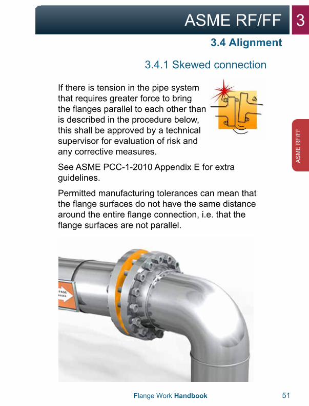
If there is tension in the pipe system that requires greater force to bring the flanges parallel to each other than is described in the procedure below, this shall be approved by a technical supervisor for evaluation of risk and any corrective measures.
See ASME PCC-1-2010 Appendix E for extra guidelines.
Permitted manufacturing tolerances can mean that the flange surfaces do not have the same distance around the entire flange connection, i.e. that the flange surfaces are not parallel.
3 ASME RF/FF
52 Flange Work Handbook
AS
ME
RF/FF
3.4 Alignment
3.4.1 Skewed connection
In such cases, the bolts must be tightened in the area where the distance between the flange surfaces is greatest.
1. The object with dealing with skews is to find outwhere the flanges have the largest gap.
2. Insert all the bolts in the flange connection.
3. With alignment of the flange connection, no morethan half of the number of bolts in the flangeconnection should be used, and neighboringbolts shall not be used so that there is alwaysat least one unused bolt between bolts that areused for alignment.
4. Tighten any bolt in the area where the gapbetween the flange surfaces is greatest, with40% of the given moment for a torque tool, or40% of the B-pressure for a wrench tool. Usethe lowest possible number of bolts to align theflanges.
5. The object when dealing with skews is to goaround the entire flange connection severaltimes during the process until the flanges areparallel.
3ASME RF/FF
Flange Work Handbook 53
AS
ME
RF/
FF
3.4 Alignment
3.4.2 Parallel shifts
Flanges that are parallel-shifted should always be aligned before tightening can begin.
1. Use available alignment tool.
2. How the alignment tool is placed depends onyour evaluation, and the space around theflange.
3. After the first alignment, all the bolts are insertedthat can move freely in the flange’s bolt holes. Ifnot all the bolts move freely, the alignment toolshould be moved, and the flange is aligned untilall the bolts move freely.
4. Lock the flange connection when the flanges areparallel. This is done by screwing in all the bolts.
WARNING:
• Never try to align the flange connection withthe help of the bolts alone.
• Always use an available alignment tool.• If you are not able to pull the flange surfaces
parallel, you should contact the nearestsupervisor.

3 ASME RF/FF
54 Flange Work Handbook
AS
ME
RF/FF
3.5 Assembly
Before tightening flanges, be sure to thoroughly plan and prepare for the job in advance.
1. Check the flange and seal surface for damage,corrosion and wear, and that the gasket surfaceis free of coatings from painting and preservative.
2. The flange’s contact surface against the nutsshould also be free of any thick layer of paintand preservative, which can cause bolts to failto tighten after assembly. Only primer paintingcan be accepted under the nut’s contact surfaceagainst the flange.
3. Clean seal surfaces. Steel brushes or approvedemery paper may be used for this. Approvedsolvents and cloths may be used for finalcleaning.
4. Clean along the edge of the gasket surface.Ensure that the cleaning does not create radialtracks on the seal surface. It is especiallyimportant to remove imperfections in a radialdirection. See ASME PCC-2-2011 Appendix D foracceptance limits of the flatness and damage onthe gasket surface.
3ASME RF/FF
Flange Work Handbook 55
AS
ME
RF/
FF
3.5 Assembly
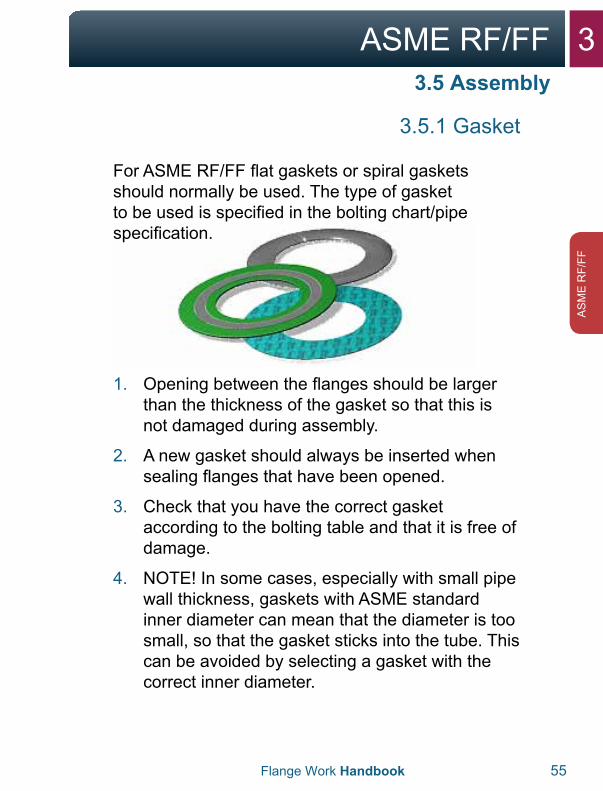
3.5.1 Gasket
For ASME RF/FF flat gaskets or spiral gaskets should normally be used. The type of gasket to be used is specified in the bolting chart/pipe specification.
1. Opening between the flanges should be largerthan the thickness of the gasket so that this isnot damaged during assembly.
2. A new gasket should always be inserted whensealing flanges that have been opened.
3. Check that you have the correct gasketaccording to the bolting table and that it is free ofdamage.
4. NOTE! In some cases, especially with small pipewall thickness, gaskets with ASME standardinner diameter can mean that the diameter is toosmall, so that the gasket sticks into the tube. Thiscan be avoided by selecting a gasket with thecorrect inner diameter.
3 ASME RF/FF
56 Flange Work Handbook
AS
ME
RF/FF
3.5 Assembly
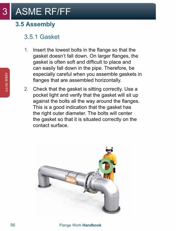
3.5.1 Gasket
1. Insert the lowest bolts in the flange so that thegasket doesn’t fall down. On larger flanges, thegasket is often soft and difficult to place andcan easily fall down in the pipe. Therefore, beespecially careful when you assemble gaskets inflanges that are assembled horizontally.
2. Check that the gasket is sitting correctly. Use apocket light and verify that the gasket will sit upagainst the bolts all the way around the flanges.This is a good indication that the gasket hasthe right outer diameter. The bolts will centerthe gasket so that it is situated correctly on thecontact surface.
3ASME RF/FF
Flange Work Handbook 57
AS
ME
RF/
FF
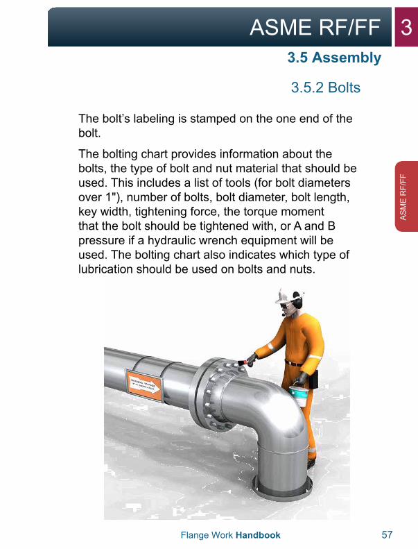
3.5.2 Bolts
The bolt’s labeling is stamped on the one end of the bolt.
The bolting chart provides information about the bolts, the type of bolt and nut material that should be used. This includes a list of tools (for bolt diameters over 1"), number of bolts, bolt diameter, bolt length, key width, tightening force, the torque moment that the bolt should be tightened with, or A and B pressure if a hydraulic wrench equipment will be used. The bolting chart also indicates which type of lubrication should be used on bolts and nuts.
3.5 Assembly
3 ASME RF/FF
58 Flange Work Handbook
AS
ME
RF/FF
3.5 Assembly
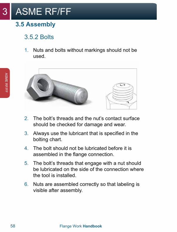
3.5.2 Bolts
1. Nuts and bolts without markings should not beused.
2. The bolt’s threads and the nut’s contact surfaceshould be checked for damage and wear.
3. Always use the lubricant that is specified in thebolting chart.
4. The bolt should not be lubricated before it isassembled in the flange connection.
5. The bolt’s threads that engage with a nut shouldbe lubricated on the side of the connection wherethe tool is installed.
6. Nuts are assembled correctly so that labeling isvisible after assembly.
3ASME RF/FF
Flange Work Handbook 59
AS
ME
RF/
FF
3.5 Assembly
3.5.2 Bolts
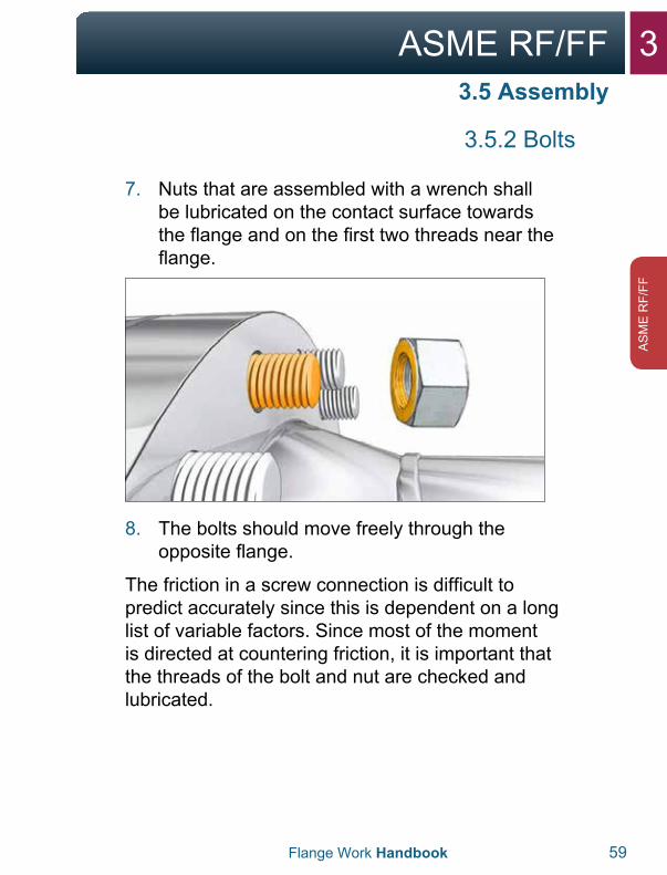
7. Nuts that are assembled with a wrench shallbe lubricated on the contact surface towardsthe flange and on the first two threads near theflange.
8. The bolts should move freely through theopposite flange.
The friction in a screw connection is difficult to predict accurately since this is dependent on a long list of variable factors. Since most of the moment is directed at countering friction, it is important that the threads of the bolt and nut are checked and lubricated.
3 ASME RF/FF
60 Flange Work Handbook
AS
ME
RF/FF
3.5 Assembly
3.5.3 Tightening
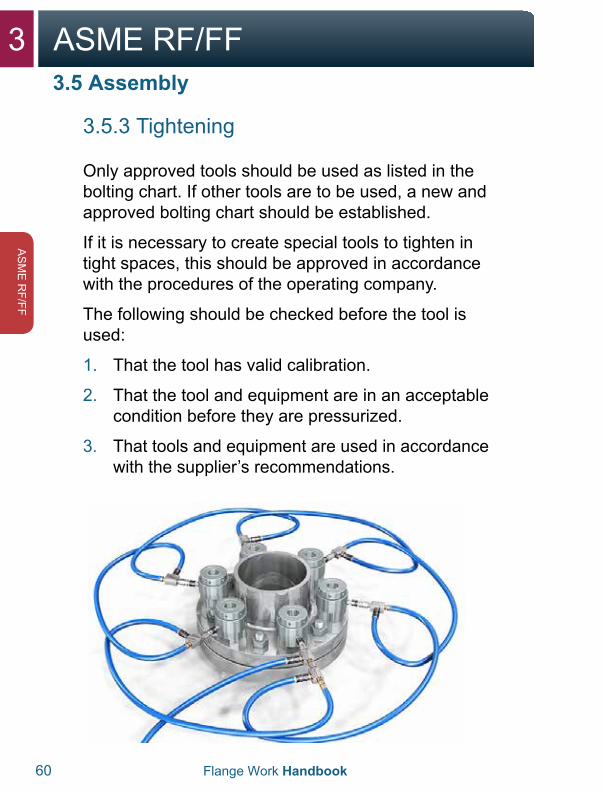
Only approved tools should be used as listed in the bolting chart. If other tools are to be used, a new and approved bolting chart should be established.
If it is necessary to create special tools to tighten in tight spaces, this should be approved in accordance with the procedures of the operating company.
The following should be checked before the tool is used:
1. That the tool has valid calibration.
2. That the tool and equipment are in an acceptablecondition before they are pressurized.
3. That tools and equipment are used in accordancewith the supplier’s recommendations.
3ASME RF/FF
Flange Work Handbook 61
AS
ME
RF/
FF
3.5.3 Tightening
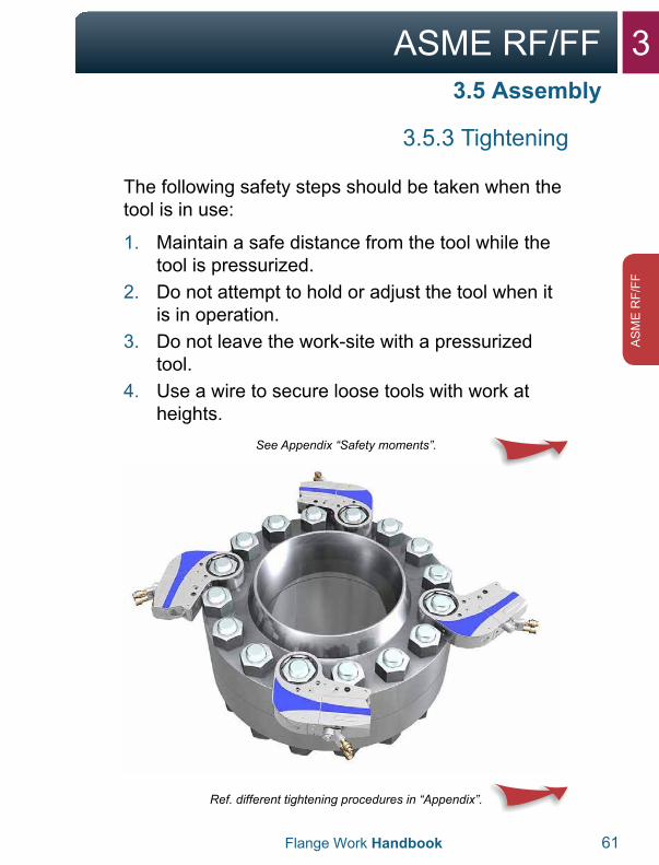
The following safety steps should be taken when the tool is in use:
1. Maintain a safe distance from the tool while thetool is pressurized.
2. Do not attempt to hold or adjust the tool when itis in operation.
3. Do not leave the work-site with a pressurizedtool.
4. Use a wire to secure loose tools with work atheights.
See Appendix “Safety moments”.
Ref. different tightening procedures in “Appendix”.
3.5 Assembly
3 ASME RF/FF
62 Flange Work Handbook
AS
ME
RF/FF
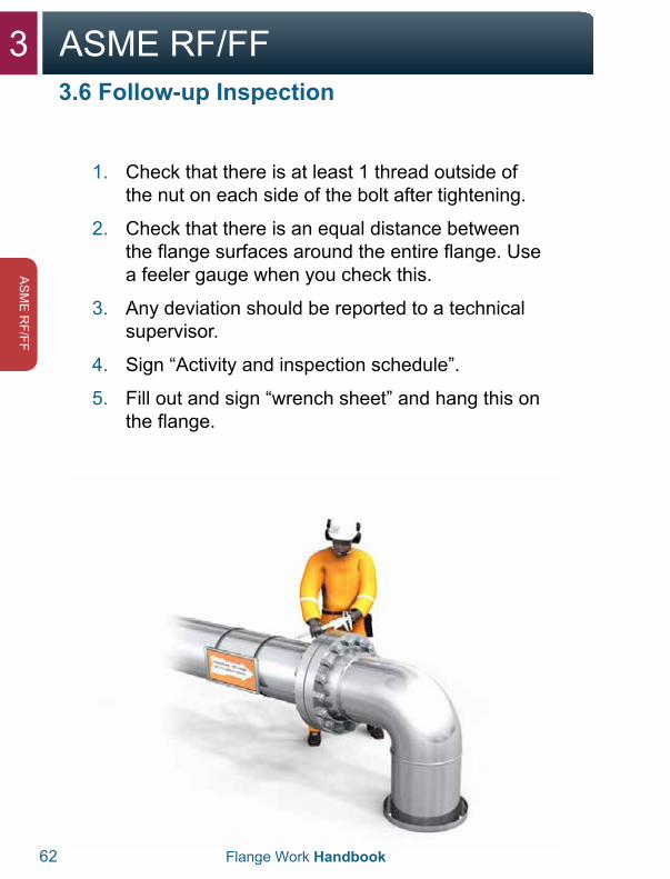
3.6 Follow-up Inspection
1. Check that there is at least 1 thread outside ofthe nut on each side of the bolt after tightening.
2. Check that there is an equal distance betweenthe flange surfaces around the entire flange. Usea feeler gauge when you check this.
3. Any deviation should be reported to a technicalsupervisor.
4. Sign “Activity and inspection schedule”.
5. Fill out and sign “wrench sheet” and hang this onthe flange.
3ASME RF/FF
Flange Work Handbook 63
AS
ME
RF/
FF
3.6 Follow-up Inspection
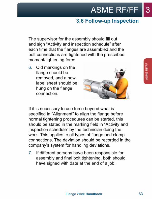
The supervisor for the assembly should fill out and sign “Activity and inspection schedule” after each time that the flanges are assembled and the bolt connections are tightened with the prescribed moment/tightening force.
6. Old markings on theflange should beremoved, and a newlabel sheet should behung on the flangeconnection.
If it is necessary to use force beyond what is specified in “Alignment” to align the flange before normal tightening procedures can be started, this should be stated in the marking field in “Activity and inspection schedule” by the technician doing the work. This applies to all types of flange and clamp connections. The deviation should be recorded in the company’s system for handling deviations.
7. If different persons have been responsible forassembly and final bolt tightening, both shouldhave signed with date at the end of a job.
3 ASME RF/FF
64 Flange Work Handbook
AS
ME
RF/FF
3.6 Follow-up Inspection
Exceptions:
For non-dangerous help/support issues, the “Activity and inspection schedule”, and labeling of the flange connections may be ignored for ASME pressure ratings of 150 and 300, where the operating temperature is between 0° and 50°C.
1. If the equipment is put in operation immediately(with the technician executing and an operationalsupervisor present), the labelling of the flangeconnection and use of “Activity and inspectionschedule” can be ignored.
2. Any type of deviations should be recorded in thecompany’s system for deviation management.
3ASME RF/FF
Flange Work Handbook 65
AS
ME
RF/
FF

4API 6A Type 6B/BX

4API 6A Type 6B/BX
4.1 Flange and Gasket Type 6B 68-69
4.1 Flange and Gasket Type 6BX 70-71
4.2 Disassembly 72-76
4.3 Inspection 77-79
4.4 Alignment 80-82
4.5 Assembly 83-87
4.6 Tightening 88-89
4.7 Follow-up Inspection 90-91
4 API 6A Type 6B/BX
68 Flange Work Handbook
API 6A Type 6B/BX
4.1 Flange and Gasket Type 6B
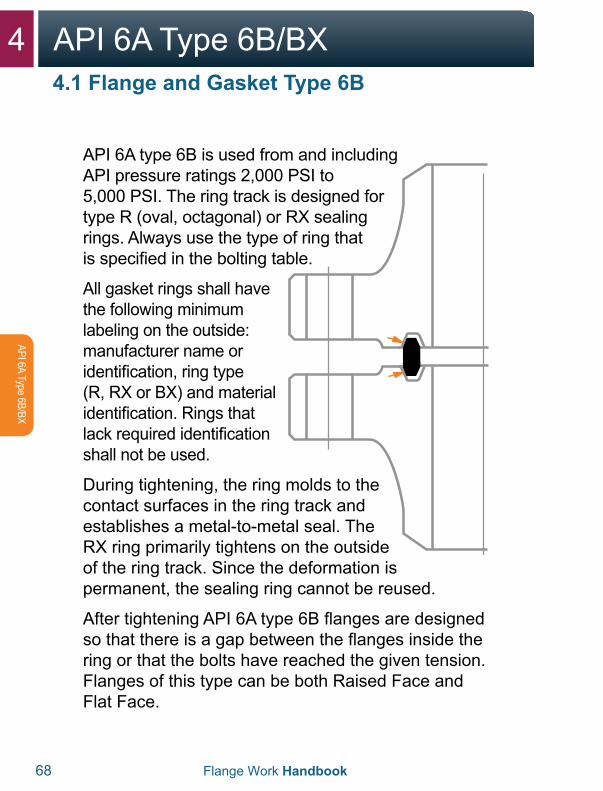
API 6A type 6B is used from and including API pressure ratings 2,000 PSI to 5,000 PSI. The ring track is designed for type R (oval, octagonal) or RX sealing rings. Always use the type of ring that is specified in the bolting table.
All gasket rings shall have the following minimum labeling on the outside: manufacturer name or identification, ring type (R, RX or BX) and material identification. Rings that lack required identification shall not be used.
During tightening, the ring molds to the contact surfaces in the ring track and establishes a metal-to-metal seal. The RX ring primarily tightens on the outside of the ring track. Since the deformation is permanent, the sealing ring cannot be reused.
After tightening API 6A type 6B flanges are designed so that there is a gap between the flanges inside the ring or that the bolts have reached the given tension. Flanges of this type can be both Raised Face and Flat Face.
4API 6A Type 6B/BX
Flange Work Handbook 69
API 6
A Ty
pe 6
B/BX
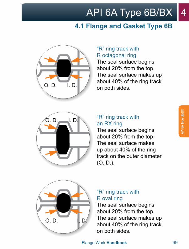
“R” ring track with R octagonal ringThe seal surface begins about 20% from the top. The seal surface makes up about 40% of the ring track on both sides.
“R” ring track with an RX ringThe seal surface begins about 20% from the top. The seal surface makes up about 40% of the ring track on the outer diameter (O. D.).
“R” ring track with R oval ringThe seal surface begins about 20% from the top. The seal surface makes up about 40% of the ring track on both sides.
4.1 Flange and Gasket Type 6B
O. D.
O. D.
O. D.
I. D.
I. D.
I. D.

4 API 6A Type 6B/BX
70 Flange Work Handbook
API 6A Type 6B/BX
4.1 Flange and Gasket Type 6BX
API 6A type 6BX is used from and including API pressure ratings 5,000 PSI to 20,000 PSI. The ring track is designed only for BX type sealing rings. The BX ring always has a hole for pressure equalization.
With tightening, the ring molds to the contact surfaces in the ring track and establishes a metal-to-metal seal that tightens on the inner and outer diameter. Since the deformation is permanent, the sealing ring cannot be reused.
After the tightening of API 6A type 6BX flanges, the flange surfaces inside by the ring shall go completely or nearly completely together (almost no measurable gap).
4API 6A Type 6B/BX
Flange Work Handbook 71
API 6
A Ty
pe 6
B/BX
4.1 Flange and Gasket Type 6BX
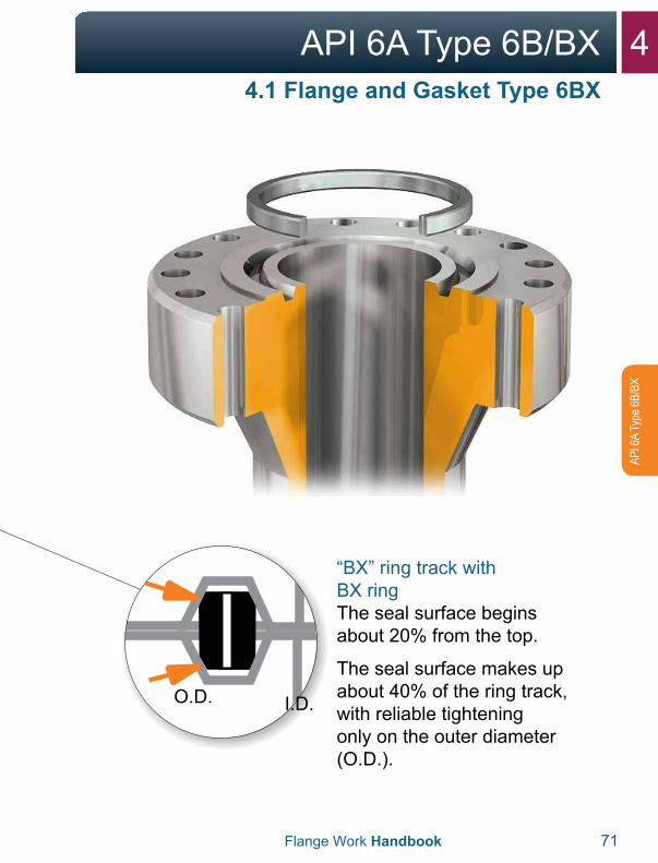
“BX” ring track with BX ringThe seal surface begins about 20% from the top.
The seal surface makes up about 40% of the ring track, with reliable tightening only on the outer diameter (O.D.).
O.D. I.D.
4 API 6A Type 6B/BX
72
API 6A Type 6B/BX
4.2 Disassembly
4.2.1 Phase 1 (loosen bolts)
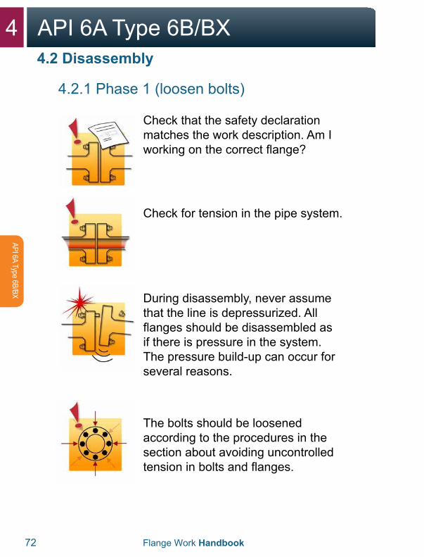
Check that the safety declaration matches the work description. Am I working on the correct flange?
Check for tension in the pipe system.
During disassembly, never assume that the line is depressurized. All flanges should be disassembled as if there is pressure in the system. The pressure build-up can occur for several reasons.
The bolts should be loosened according to the procedures in the section about avoiding uncontrolled tension in bolts and flanges.
Flange Work Handbook
4API 6A Type 6B/BX
Flange Work Handbook 73
API 6
A Ty
pe 6
B/BX
4.2 Disassembly
4.2.1 Phase 1 (loosen bolts)
CHECK THAT RELEVANT HSE PROCEDURES ARE FOLLOWED.
All deviations shall be logged in the “Activity and inspection schedule”, under “Notes” or on the back side.
4 API 6A Type 6B/BX
74 Flange Work Handbook
API 6A Type 6B/BX
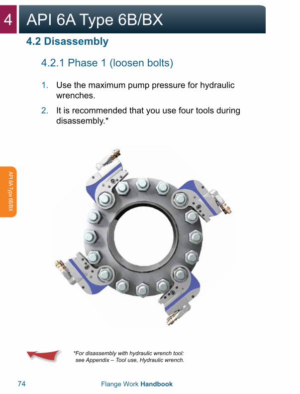
4.2 Disassembly
4.2.1 Phase 1 (loosen bolts)
1. Use the maximum pump pressure for hydraulicwrenches.
2. It is recommended that you use four tools duringdisassembly.*
* For disassembly with hydraulic wrench tool:see Appendix – Tool use, Hydraulic wrench.
4API 6A Type 6B/BX
Flange Work Handbook 75
API 6
A Ty
pe 6
B/BX
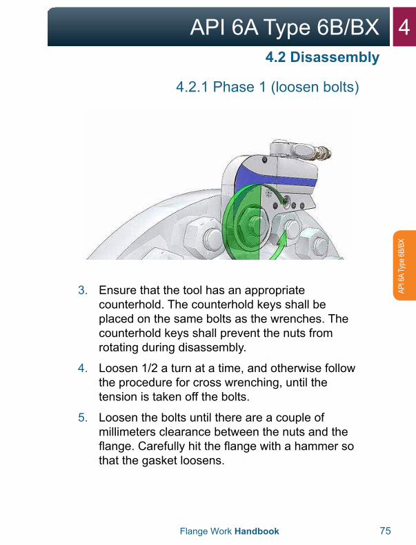
4.2 Disassembly
4.2.1 Phase 1 (loosen bolts)
3. Ensure that the tool has an appropriatecounterhold. The counterhold keys shall beplaced on the same bolts as the wrenches. Thecounterhold keys shall prevent the nuts fromrotating during disassembly.
4. Loosen 1/2 a turn at a time, and otherwise followthe procedure for cross wrenching, until thetension is taken off the bolts.
5. Loosen the bolts until there are a couple ofmillimeters clearance between the nuts and theflange. Carefully hit the flange with a hammer sothat the gasket loosens.
4 API 6A Type 6B/BX
76 Flange Work Handbook
API 6A Type 6B/BX
4.2 Disassembly
4.2.2 Phase 2 (open flange)
WARNING:With use of a hydraulic spreader, it is important to remember the following:
• If there is one or more bolts stuck in theflange’s bolt hole, this can mean that there istension in the pipe system. In that case, greatcare should be taken in further disassembly ofthe flange, and potentially securing the pipeshould be considered.
WARNING:With use of a hydraulic spreader, it is important to remember the following:
• Never stick fingers between the flanges beforea safety block is installed and the spreadersare unloaded.
• Use the handle on the spreader when takingout or moving the tool.

4API 6A Type 6B/BX
Flange Work Handbook 77
API 6
A Ty
pe 6
B/BX
4.3.1 Phase 2 (open flange)
1. For safety reasons, not all bolts should be takenout before the flange is open.
2. Use two spreaders,hydraulic or mechanical,opposite each other. Thisyields an even opening ofthe flange.
3. It is important that thespreaders have fullcontact with both flangesurfaces before they arepressurized.
4. Insert safety blocks whenthe desired opening isreached using hydraulicspreaders. The flangeswill then rest on the safetyblocks.
5. Keep the lowest bolts toprevent the sealing ringfrom falling out.
6. Then take out the sealing ring with its own tool.Be careful so that the gasket track and flange arenot damaged.
4.3 Inspection
4 API 6A Type 6B/BX
78 Flange Work Handbook
API 6A Type 6B/BX
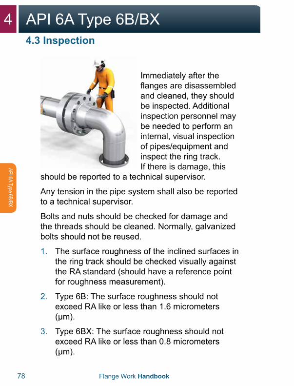
4.3 Inspection
Immediately after the flanges are disassembled and cleaned, they should be inspected. Additional inspection personnel may be needed to perform an internal, visual inspection of pipes/equipment and inspect the ring track. If there is damage, this
should be reported to a technical supervisor.
Any tension in the pipe system shall also be reported to a technical supervisor.
Bolts and nuts should be checked for damage and the threads should be cleaned. Normally, galvanized bolts should not be reused.
1. The surface roughness of the inclined surfaces inthe ring track should be checked visually againstthe RA standard (should have a reference pointfor roughness measurement).
2. Type 6B: The surface roughness should notexceed RA like or less than 1.6 micrometers(μm).
3. Type 6BX: The surface roughness should notexceed RA like or less than 0.8 micrometers(μm).
4API 6A Type 6B/BX
Flange Work Handbook 79
API 6
A Ty
pe 6
B/BX
4.3 Inspection
4.3.2 Inspection – Troubleshooting
For more information about troubleshooting leaking flanges refer to: Appendix “Checklist for leaking flanges”.
For more information about inspection and repair of flanges, refer to API 574 and ASME PCC-2-2011 article 3.5.
If the flanges are not assembled immediately, the gasket surface should be protected.
4 API 6A Type 6B/BX
80 Flange Work Handbook
API 6A Type 6B/BX
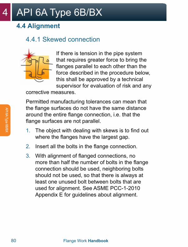
4.4.1 Skewed connection
If there is tension in the pipe system that requires greater force to bring the flanges parallel to each other than the force described in the procedure below, this shall be approved by a technical supervisor for evaluation of risk and any
corrective measures.
Permitted manufacturing tolerances can mean that the flange surfaces do not have the same distance around the entire flange connection, i.e. that the flange surfaces are not parallel.
1. The object with dealing with skews is to find outwhere the flanges have the largest gap.
2. Insert all the bolts in the flange connection.
3. With alignment of flanged connections, nomore than half the number of bolts in the flangeconnection should be used, neighboring boltsshould not be used, so that there is always atleast one unused bolt between bolts that areused for alignment. See ASME PCC-1-2010Appendix E for guidelines about alignment.
4.4 Alignment
4API 6A Type 6B/BX
Flange Work Handbook 81
API 6
A Ty
pe 6
B/BX
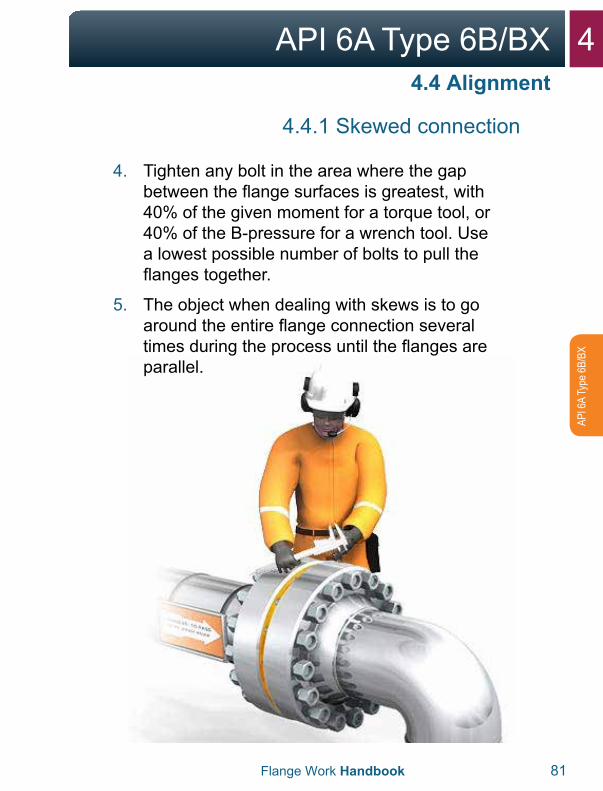
4.4.1 Skewed connection
4. Tighten any bolt in the area where the gapbetween the flange surfaces is greatest, with40% of the given moment for a torque tool, or40% of the B-pressure for a wrench tool. Usea lowest possible number of bolts to pull theflanges together.
5. The object when dealing with skews is to goaround the entire flange connection severaltimes during the process until the flanges areparallel.
4.4 Alignment
4 API 6A Type 6B/BX
82 Flange Work Handbook
API 6A Type 6B/BX
4.4 Alignment
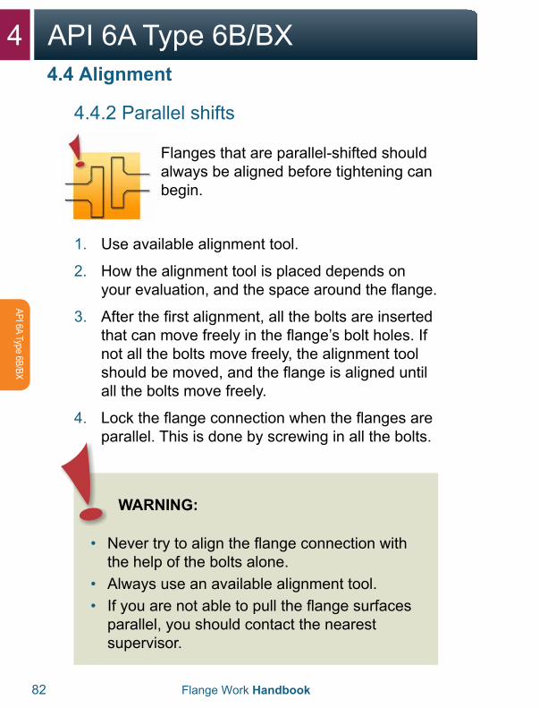
4.4.2 Parallel shifts
Flanges that are parallel-shifted should always be aligned before tightening can begin.
1. Use available alignment tool.
2. How the alignment tool is placed depends onyour evaluation, and the space around the flange.
3. After the first alignment, all the bolts are insertedthat can move freely in the flange’s bolt holes. Ifnot all the bolts move freely, the alignment toolshould be moved, and the flange is aligned untilall the bolts move freely.
4. Lock the flange connection when the flanges areparallel. This is done by screwing in all the bolts.
WARNING:
• Never try to align the flange connection withthe help of the bolts alone.
• Always use an available alignment tool.• If you are not able to pull the flange surfaces
parallel, you should contact the nearestsupervisor.
4API 6A Type 6B/BX
Flange Work Handbook 83
API 6
A Ty
pe 6
B/BX
4.5 Assembly
Before tightening flanges, be sure to thoroughly plan and prepare for the job in advance.
1. Flange and seal surface are checked fordamage, corrosion and wear, and that the sealsurface is free of coatings from painting andpreservatives in the seal track and on both sidesof this.
2. The flange’s contact surface against the nutsshould also be free of any thick layer of paintand preservative, which can cause bolts to fail totighten after assembly. Only primer is acceptableunder nuts.
3. Clean seal surfaces. Steel brushes or approvedemery paper may be used for this. Approvedsolvents and cloths may be used for finalcleaning.
4. Clean along the ring track. Ensure that thecleaning does not cause radial tracks in thering track. It is especially important to removeimperfections in a radial direction.
4 API 6A Type 6B/BX
84 Flange Work Handbook
API 6A Type 6B/BX
4.5 Assembly
4.5.1 Sealing ring
For API 6A type 6B flanges, R and RX metal rings may be used. For API 6A type 6BX flanges, BX metal rings may be used. The type of ring to be used is specified in the bolting chart/pipe specification.
1. Opening between the flanges should be largerthan the thickness of the sealing ring so that thisis not damaged during assembly.
2. A new sealing ring should always be insertedwhen sealing flanges that have been opened.
3. Check that you have the correct sealing ringaccording to the bolting table and that it is free ofdamage. All gasket rings shall have the followingminimum labeling on the outside: manufacturername or identification, ring type (R, RX or BX)and material identification.
4. Rings with incomplete markings should not beused.
5. Insert the lowest bolts in the flange connectionso that the sealing ring doesn’t fall out.
4API 6A Type 6B/BX
Flange Work Handbook 85
API 6
A Ty
pe 6
B/BX
4.5 Assembly
4.5.1 Sealing ring
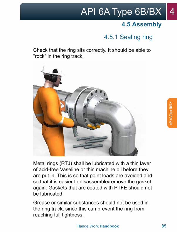
Check that the ring sits correctly. It should be able to “rock” in the ring track.
Metal rings (RTJ) shall be lubricated with a thin layer of acid-free Vaseline or thin machine oil before they are put in. This is so that point loads are avoided and so that it is easier to disassemble/remove the gasket again. Gaskets that are coated with PTFE should not be lubricated.
Grease or similar substances should not be used in the ring track, since this can prevent the ring from reaching full tightness.
4 API 6A Type 6B/BX
86 Flange Work Handbook
API 6A Type 6B/BX
4.5 Assembly
4.5.2 Bolts
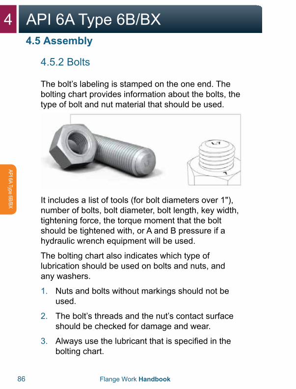
The bolt’s labeling is stamped on the one end. The bolting chart provides information about the bolts, the type of bolt and nut material that should be used.
It includes a list of tools (for bolt diameters over 1"), number of bolts, bolt diameter, bolt length, key width, tightening force, the torque moment that the bolt should be tightened with, or A and B pressure if a hydraulic wrench equipment will be used.
The bolting chart also indicates which type of lubrication should be used on bolts and nuts, and any washers.
1. Nuts and bolts without markings should not beused.
2. The bolt’s threads and the nut’s contact surfaceshould be checked for damage and wear.
3. Always use the lubricant that is specified in thebolting chart.
4API 6A Type 6B/BX
Flange Work Handbook 87
API 6
A Ty
pe 6
B/BX
4.5.2 Bolts
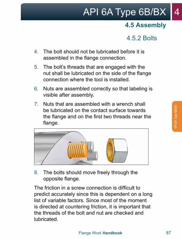
4. The bolt should not be lubricated before it isassembled in the flange connection.
5. The bolt’s threads that are engaged with thenut shall be lubricated on the side of the flangeconnection where the tool is installed.
6. Nuts are assembled correctly so that labeling isvisible after assembly.
7. Nuts that are assembled with a wrench shallbe lubricated on the contact surface towardsthe flange and on the first two threads near theflange.
8. The bolts should move freely through theopposite flange.
The friction in a screw connection is difficult to predict accurately since this is dependent on a long list of variable factors. Since most of the moment is directed at countering friction, it is important that the threads of the bolt and nut are checked and lubricated.
4.5 Assembly
4 API 6A Type 6B/BX
88 Flange Work Handbook
API 6A Type 6B/BX
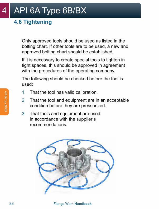
4.6 Tightening
Only approved tools should be used as listed in the bolting chart. If other tools are to be used, a new and approved bolting chart should be established.
If it is necessary to create special tools to tighten in tight spaces, this should be approved in agreement with the procedures of the operating company.
The following should be checked before the tool is used:
1. That the tool has valid calibration.
2. That the tool and equipment are in an acceptablecondition before they are pressurized.
3. That tools and equipment are usedin accordance with the supplier’srecommendations.
4API 6A Type 6B/BX
Flange Work Handbook 89
API 6
A Ty
pe 6
B/BX
4.6 Tightening
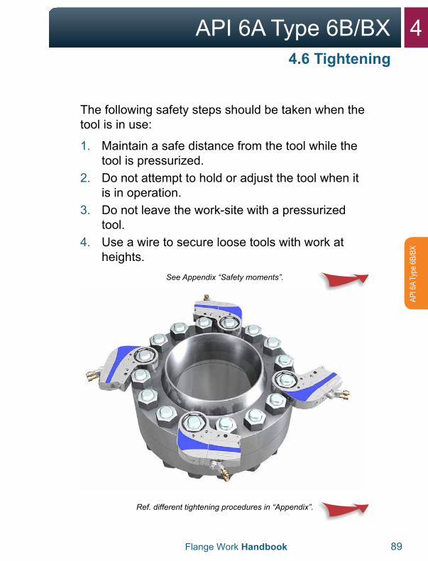
The following safety steps should be taken when the tool is in use:
1. Maintain a safe distance from the tool while thetool is pressurized.
2. Do not attempt to hold or adjust the tool when itis in operation.
3. Do not leave the work-site with a pressurizedtool.
4. Use a wire to secure loose tools with work atheights.
See Appendix “Safety moments”.
Ref. different tightening procedures in “Appendix”.
4 API 6A Type 6B/BX
90 Flange Work Handbook
API 6A Type 6B/BX
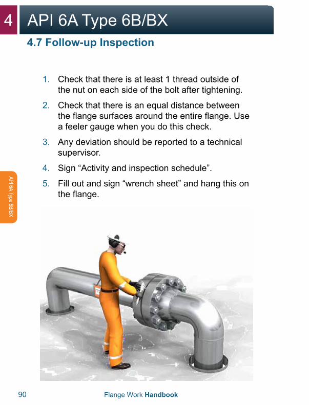
1. Check that there is at least 1 thread outside ofthe nut on each side of the bolt after tightening.
2. Check that there is an equal distance betweenthe flange surfaces around the entire flange. Usea feeler gauge when you do this check.
3. Any deviation should be reported to a technicalsupervisor.
4. Sign “Activity and inspection schedule”.
5. Fill out and sign “wrench sheet” and hang this onthe flange.
4.7 Follow-up Inspection
4API 6A Type 6B/BX
Flange Work Handbook 91
API 6
A Ty
pe 6
B/BX
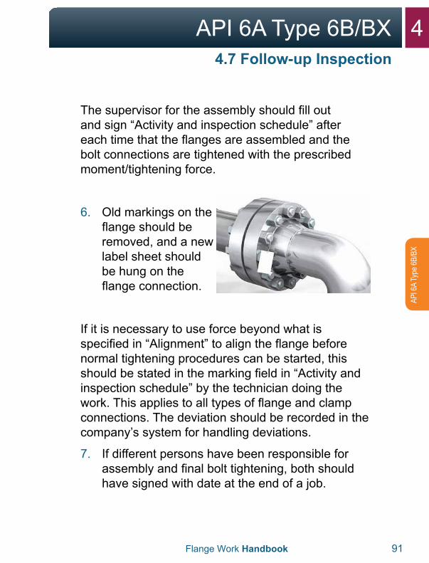
The supervisor for the assembly should fill out and sign “Activity and inspection schedule” after each time that the flanges are assembled and the bolt connections are tightened with the prescribed moment/tightening force.
6. Old markings on theflange should beremoved, and a newlabel sheet shouldbe hung on theflange connection.
If it is necessary to use force beyond what is specified in “Alignment” to align the flange before normal tightening procedures can be started, this should be stated in the marking field in “Activity and inspection schedule” by the technician doing the work. This applies to all types of flange and clamp connections. The deviation should be recorded in the company’s system for handling deviations.
7. If different persons have been responsible forassembly and final bolt tightening, both shouldhave signed with date at the end of a job.
4.7 Follow-up Inspection

5NCF5 Compact
5NCF5 Compact
5.1 Flange and Gasket 94-95
5.2 Disassembly 96-103
5.3 Inspection 104-108
5.4 Alignment 109-113
5.5 Assembly 114-119
5.6 Tightening 120-121
5.7 Follow-up Inspection 122-123
5 NCF5 Compact
94 Flange Work Handbook
NC
F5 Com
pact
5.1 Flange and Gasket
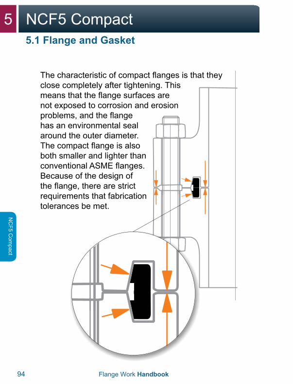
The characteristic of compact flanges is that they close completely after tightening. This means that the flange surfaces are not exposed to corrosion and erosion problems, and the flange has an environmental seal around the outer diameter. The compact flange is also both smaller and lighter than conventional ASME flanges. Because of the design of the flange, there are strict requirements that fabrication tolerances be met.
5NCF5 Compact
Flange Work Handbook 95
NC
F5 C
ompa
ct
5.1 Flange and Gasket
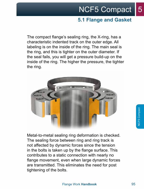
The compact flange’s sealing ring, the X-ring, has a characteristic indented track on the outer edge. All labeling is on the inside of the ring. The main seal is the ring, and this is tighter on the outer diameter. If the seal fails, you will get a pressure build-up on the inside of the ring. The higher the pressure, the tighter the ring.
Metal-to-metal sealing ring deformation is checked. The sealing force between ring and ring track is not affected by dynamic forces since the tension in the bolts is taken up by the flange surface. This contributes to a static connection with nearly no flange movement, even when large dynamic forces are transmitted. This eliminates the need for post tightening of the bolts.
5 NCF5 Compact
96 Flange Work Handbook
NC
F5 Com
pact
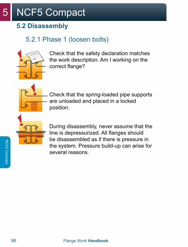
5.2.1 Phase 1 (loosen bolts)
Check that the safety declaration matches the work description. Am I working on the correct flange?
Check that the spring-loaded pipe supports are unloaded and placed in a locked position.
During disassembly, never assume that the line is depressurized. All flanges should be disassembled as if there is pressure in the system. Pressure build-up can arise for several reasons.
5.2 Disassembly
5NCF5 Compact
Flange Work Handbook 97
NC
F5 C
ompa
ct
5.2.1 Phase 1 (loosen bolts)
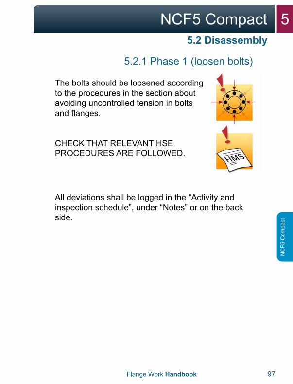
The bolts should be loosened according to the procedures in the section about avoiding uncontrolled tension in bolts and flanges.
CHECK THAT RELEVANT HSE PROCEDURES ARE FOLLOWED.
All deviations shall be logged in the “Activity and inspection schedule”, under “Notes” or on the back side.
5.2 Disassembly
5 NCF5 Compact
98 Flange Work Handbook
NC
F5 Com
pact
5.2 Disassembly
5.2.1 Phase 1 (loosen bolts)
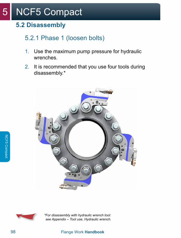
1. Use the maximum pump pressure for hydraulicwrenches.
2. It is recommended that you use four tools duringdisassembly.*
* For disassembly with hydraulic wrench tool:see Appendix – Tool use, Hydraulic wrench.
5NCF5 Compact
Flange Work Handbook 99
NC
F5 C
ompa
ct
5.2 Disassembly
5.2.1 Phase 1 (loosen bolts)
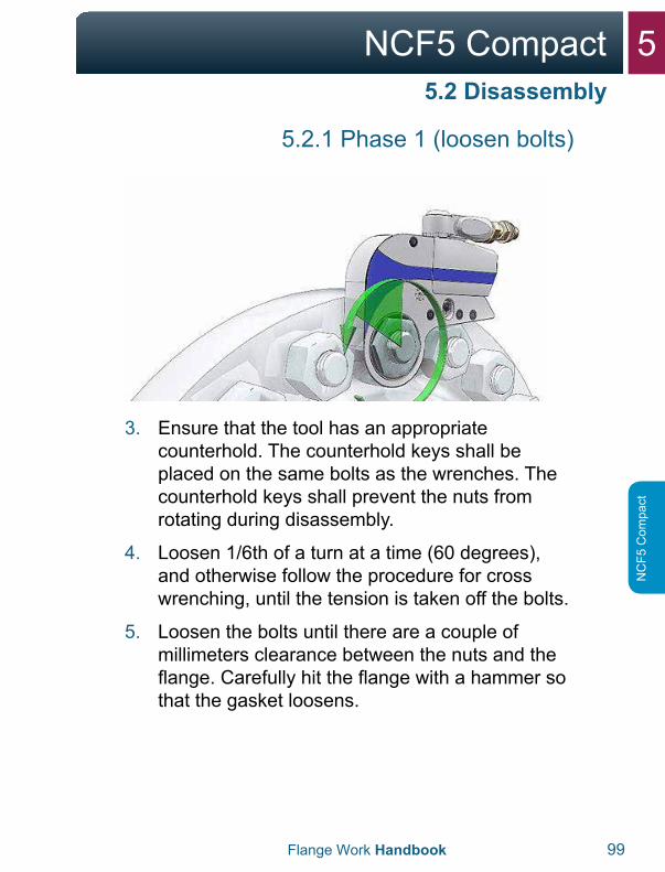
3. Ensure that the tool has an appropriatecounterhold. The counterhold keys shall beplaced on the same bolts as the wrenches. Thecounterhold keys shall prevent the nuts fromrotating during disassembly.
4. Loosen 1/6th of a turn at a time (60 degrees),and otherwise follow the procedure for crosswrenching, until the tension is taken off the bolts.
5. Loosen the bolts until there are a couple ofmillimeters clearance between the nuts and theflange. Carefully hit the flange with a hammer sothat the gasket loosens.
5 NCF5 Compact
100 Flange Work Handbook
NC
F5 Com
pact
5.2 Disassembly
5.2.2 Phase 2 (open flange)
WARNING:With use of a hydraulic spreader, it is important to remember the following:
• If there is one or more bolts stuck in theflange’s bolt hole, this can mean that there istension in the pipe system. In that case, greatcare should be taken in further disassembly ofthe flange, and potentially securing the pipeshould be considered.
WARNING:With use of a hydraulic spreader, it is important to remember the following:
• Never stick fingers between the flanges beforea safety block is installed and the spreadersare unloaded.
• Use the handle on the spreader when takingout or moving the tool.
5NCF5 Compact
Flange Work Handbook 101
NC
F5 C
ompa
ct
5.2 Disassembly
5.2.2 Phase 2 (open flange)
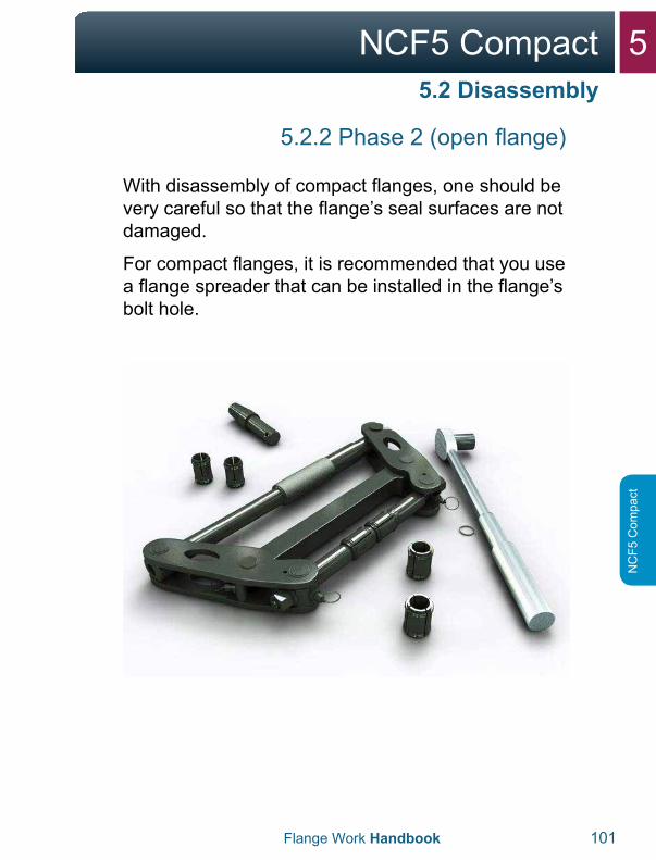
With disassembly of compact flanges, one should be very careful so that the flange’s seal surfaces are not damaged.
For compact flanges, it is recommended that you use a flange spreader that can be installed in the flange’s bolt hole.
5 NCF5 Compact
102 Flange Work Handbook
NC
F5 Com
pact
5.2 Disassembly
5.2.2 Phase 2 (open flange)
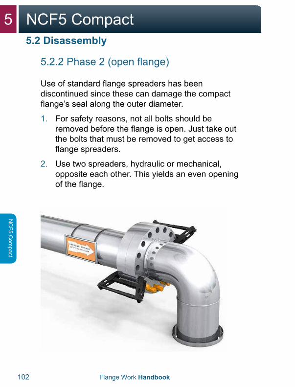
Use of standard flange spreaders has been discontinued since these can damage the compact flange’s seal along the outer diameter.
1. For safety reasons, not all bolts should beremoved before the flange is open. Just take outthe bolts that must be removed to get access toflange spreaders.
2. Use two spreaders, hydraulic or mechanical,opposite each other. This yields an even openingof the flange.
5NCF5 Compact
Flange Work Handbook 103
NC
F5 C
ompa
ct
5.2 Disassembly
5.2.2 Phase 2 (open flange)
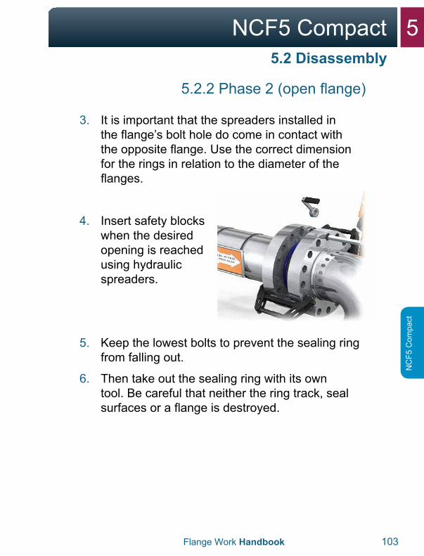
3. It is important that the spreaders installed inthe flange’s bolt hole do come in contact withthe opposite flange. Use the correct dimensionfor the rings in relation to the diameter of theflanges.
4. Insert safety blockswhen the desiredopening is reachedusing hydraulicspreaders.
5. Keep the lowest bolts to prevent the sealing ringfrom falling out.
6. Then take out the sealing ring with its owntool. Be careful that neither the ring track, sealsurfaces or a flange is destroyed.
5 NCF5 Compact
104 Flange Work Handbook
NC
F5 Com
pact
5.3 Inspection
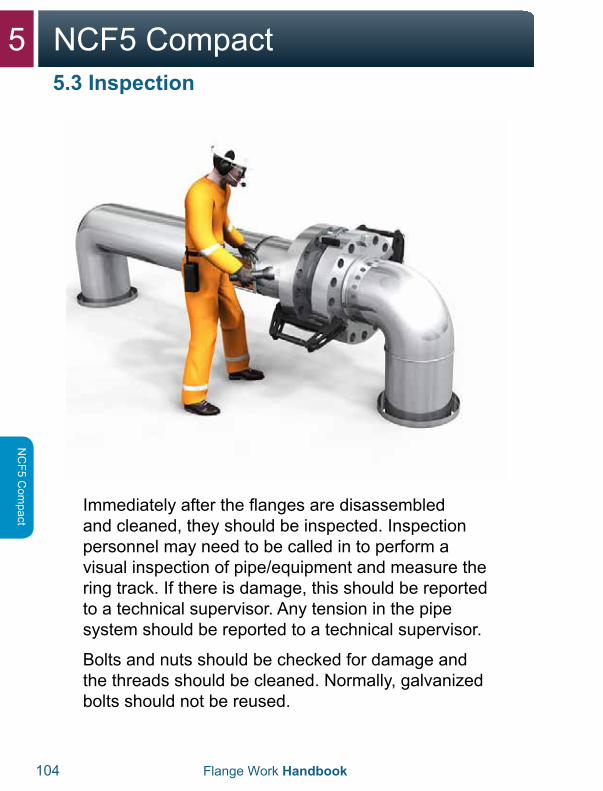
Immediately after the flanges are disassembled and cleaned, they should be inspected. Inspection personnel may need to be called in to perform a visual inspection of pipe/equipment and measure the ring track. If there is damage, this should be reported to a technical supervisor. Any tension in the pipe system should be reported to a technical supervisor.
Bolts and nuts should be checked for damage and the threads should be cleaned. Normally, galvanized bolts should not be reused.
5NCF5 Compact
Flange Work Handbook 105
NC
F5 C
ompa
ct
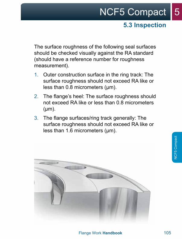
The surface roughness of the following seal surfaces should be checked visually against the RA standard (should have a reference number for roughness measurement).
1. Outer construction surface in the ring track: Thesurface roughness should not exceed RA like orless than 0.8 micrometers (μm).
2. The flange’s heel: The surface roughness shouldnot exceed RA like or less than 0.8 micrometers(μm).
3. The flange surfaces/ring track generally: Thesurface roughness should not exceed RA like orless than 1.6 micrometers (μm).
5.3 Inspection

5 NCF5 Compact
106 Flange Work Handbook
NC
F5 Com
pact
5.3 Inspection
Polish away all types of slight damage to the seal surfaces, the heel and the contact surfaces in the ring track with a fine polishing cloth in the direction of the flange circle. Significant flange damage usually requires remachining. Contact the flange supplier for machining tolerances and advice about acceptable machining.
5NCF5 Compact
Flange Work Handbook 107
NC
F5 C
ompa
ct
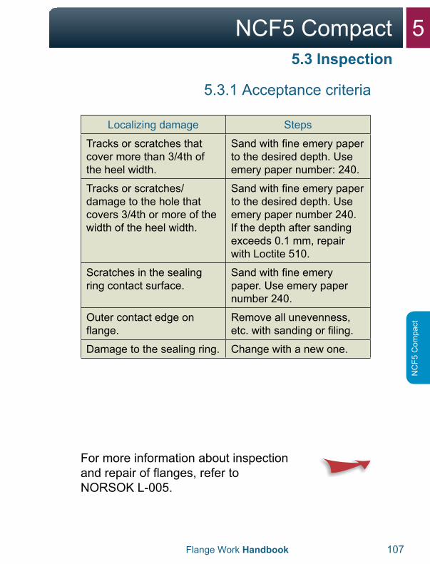
5.3.1 Acceptance criteria
Localizing damage Steps
Tracks or scratches that cover more than 3/4th of the heel width.
Sand with fine emery paper to the desired depth. Use emery paper number: 240.
Tracks or scratches/damage to the hole that covers 3/4th or more of the width of the heel width.
Sand with fine emery paper to the desired depth. Use emery paper number 240. If the depth after sanding exceeds 0.1 mm, repair with Loctite 510.
Scratches in the sealing ring contact surface.
Sand with fine emery paper. Use emery paper number 240.
Outer contact edge on flange.
Remove all unevenness, etc. with sanding or filing.
Damage to the sealing ring. Change with a new one.
For more information about inspection and repair of flanges, refer to NORSOK L-005.
5.3 Inspection
5 NCF5 Compact
108 Flange Work Handbook
NC
F5 Com
pact
5.3 Inspection
For more information about inspection and repair of flanges, refer to NORSOK L-005.
For more information about troubleshooting with leakage of flanges refer to: Appendix – “Checklist for leaking flanges”.
If the flanges are not assembled immediately, the gasket surface should be protected.
5NCF5 Compact
Flange Work Handbook 109
NC
F5 C
ompa
ct
5.4.1 Skewed connection
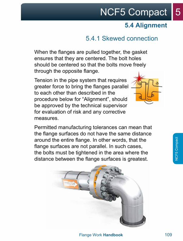
When the flanges are pulled together, the gasket ensures that they are centered. The bolt holes should be centered so that the bolts move freely through the opposite flange.
Tension in the pipe system that requires greater force to bring the flanges parallel to each other than described in the procedure below for “Alignment”, should be approved by the technical supervisor for evaluation of risk and any corrective measures.
Permitted manufacturing tolerances can mean that the flange surfaces do not have the same distance around the entire flange. In other words, that the flange surfaces are not parallel. In such cases, the bolts must be tightened in the area where the distance between the flange surfaces is greatest.
5.4 Alignment
5 NCF5 Compact
110 Flange Work Handbook
NC
F5 Com
pact
5.4 Alignment
5.4.1 Skewed connection
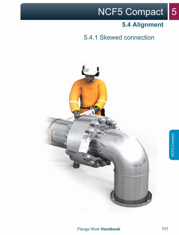
The goal of handling skews is to find out where the flanges have the largest gap.
1. Insert all the bolts in the flange.
2. When aligning flanged connections, no morethan half the number of bolts in the flangeconnection should be used.
3. Neighboring bolts should not be used, so thatthere is always at least one unused bolt betweenbolts that are used for alignment.
4. None of the used bolts should be loaded morethan 30% of the given moment in the boltingchart. (Moment for compact flanges is given inNORSOK L-005, part 5.)
5. The object when dealing with skews is to goaround the entire flange connection severaltimes during the process until the flanges areparallel.
5NCF5 Compact
Flange Work Handbook 111
NC
F5 C
ompa
ct
5.4.1 Skewed connection
5.4 Alignment
5 NCF5 Compact
112 Flange Work Handbook
NC
F5 Com
pact
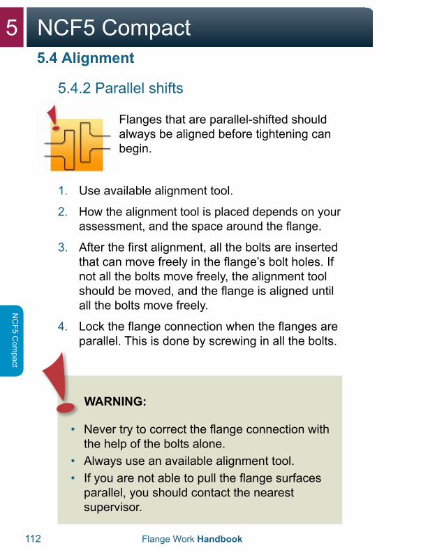
5.4.2 Parallel shifts
Flanges that are parallel-shifted should always be aligned before tightening can begin.
1. Use available alignment tool.
2. How the alignment tool is placed depends on yourassessment, and the space around the flange.
3. After the first alignment, all the bolts are insertedthat can move freely in the flange’s bolt holes. Ifnot all the bolts move freely, the alignment toolshould be moved, and the flange is aligned untilall the bolts move freely.
4. Lock the flange connection when the flanges areparallel. This is done by screwing in all the bolts.
5.4 Alignment
WARNING:
• Never try to correct the flange connection withthe help of the bolts alone.
• Always use an available alignment tool.• If you are not able to pull the flange surfaces
parallel, you should contact the nearestsupervisor.
5NCF5 Compact
Flange Work Handbook 113
NC
F5 C
ompa
ct
5.4.2 Parallel shifts
Before tightening flanges, be sure to thoroughly plan and prepare for the job in advance.
1. Flange, gasket surfaces and ring tracks arechecked for damage, corrosion and wear, andthat the seal surface is free of coatings frompainting and preservative in the gasket surface.
2. The flange’s contact surface against the nutsshould also be free of any paint and preservative.Only primer is permitted.
3. Clean the ring track, seal surface and heel andalong the outer diameter. Approved emery papermay be used for this. Approved solvents andcloths may be used for final cleaning. Cleanalong the ring track and along the heel and outerdiameter, so that there are no radial tracks onthe surfaces. You should pay careful attention todamage in a radial direction.
5.4 Alignment
5 NCF5 Compact
114 Flange Work Handbook
NC
F5 Com
pact
5.5 Assembly

5NCF5 Compact
Flange Work Handbook 115
NC
F5 C
ompa
ct
5.5.1 Sealing ring
For NCF5 Compact only IX rings can be used. The required material quality for the ring to be used is specified in the bolting chart/pipe specification. IX rings for compact flanges with the designation NCF5 have a color code and material information as in NORSOK L-005:
BLUE: Carbon steelYELLOW: 22Cr. Duplex steelBLACK: 6Mo Austenitic steelORANGE: 17/4 PH Martensitic steel
Check all of the markings on the ring to be certain that it has the correct material quality in the event of a deviation within the color coding.
5.5 Assembly
5 NCF5 Compact
116 Flange Work Handbook
NC
F5 Com
pact
5.5.1 Sealing ring
1. Opening between the flanges should be largerthan the thickness of the sealing ring so that thisis not damaged during assembly.
2. A new sealing ring should always be insertedwhen sealing flanges that have been opened.
3. Check that you have the correct sealing ringaccording to the table and that it is free ofdamage. The ring’s size and material quality ismarked on the ring.
4. Insert the lowest bolts in the flange connectionso that the sealing ring doesn’t fall out.
5. Check that the ring sits correctly. It should beable to “rock” in the ring track.
5.5 Assembly
5NCF5 Compact
Flange Work Handbook 117
NC
F5 C
ompa
ct
5.5.1 Sealing ring
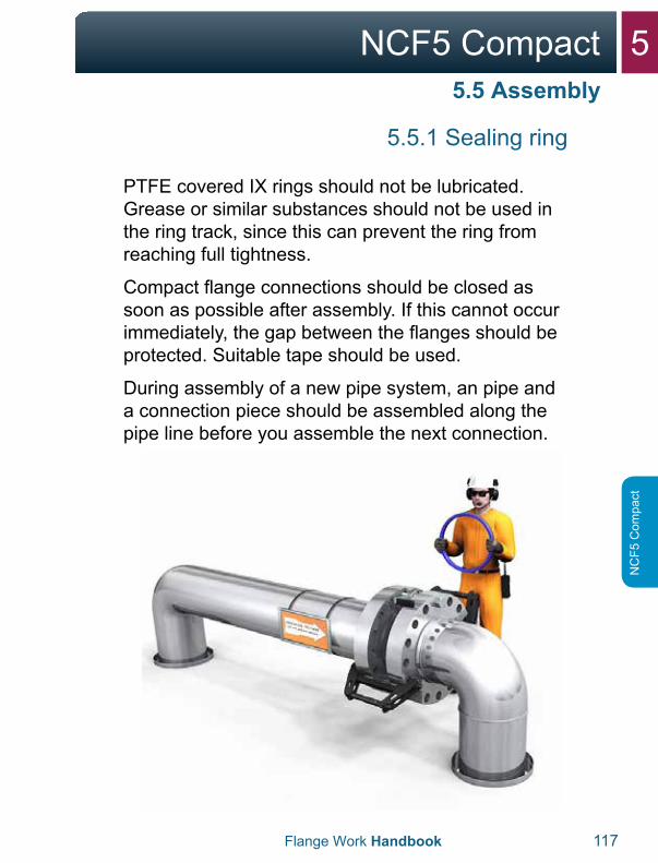
PTFE covered IX rings should not be lubricated. Grease or similar substances should not be used in the ring track, since this can prevent the ring from reaching full tightness.
Compact flange connections should be closed as soon as possible after assembly. If this cannot occur immediately, the gap between the flanges should be protected. Suitable tape should be used.
During assembly of a new pipe system, an pipe and a connection piece should be assembled along the pipe line before you assemble the next connection.
5.5 Assembly
5 NCF5 Compact
118 Flange Work Handbook
NC
F5 Com
pact
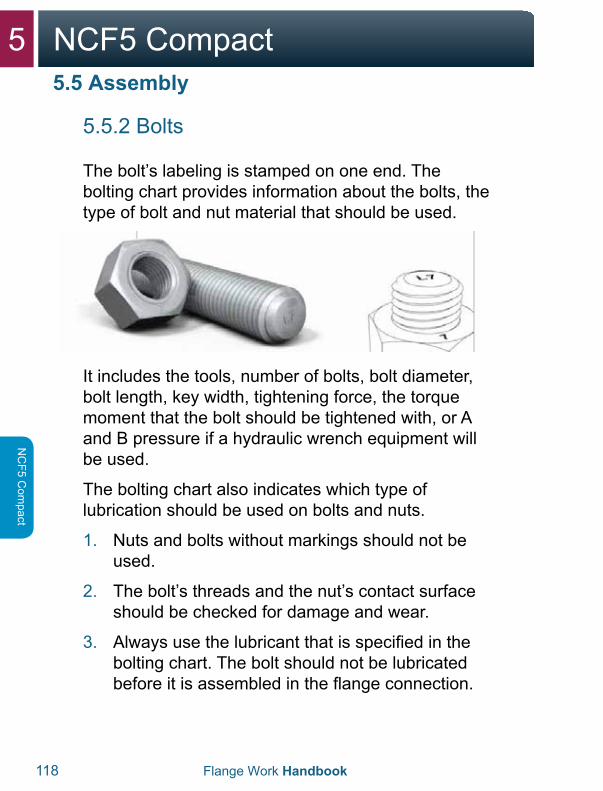
5.5.2 Bolts
The bolt’s labeling is stamped on one end. The bolting chart provides information about the bolts, the type of bolt and nut material that should be used.
It includes the tools, number of bolts, bolt diameter, bolt length, key width, tightening force, the torque moment that the bolt should be tightened with, or A and B pressure if a hydraulic wrench equipment will be used.
The bolting chart also indicates which type of lubrication should be used on bolts and nuts.
1. Nuts and bolts without markings should not beused.
2. The bolt’s threads and the nut’s contact surfaceshould be checked for damage and wear.
3. Always use the lubricant that is specified in thebolting chart. The bolt should not be lubricatedbefore it is assembled in the flange connection.
5.5 Assembly
5NCF5 Compact
Flange Work Handbook 119
NC
F5 C
ompa
ct
5.5.2 Bolts
4. The bolt’s threads that engage with a nut shouldbe lubricated on the side of the connection wherethe tool is installed.
5. Nuts are assembled correctly so that labeling isvisible after assembly.
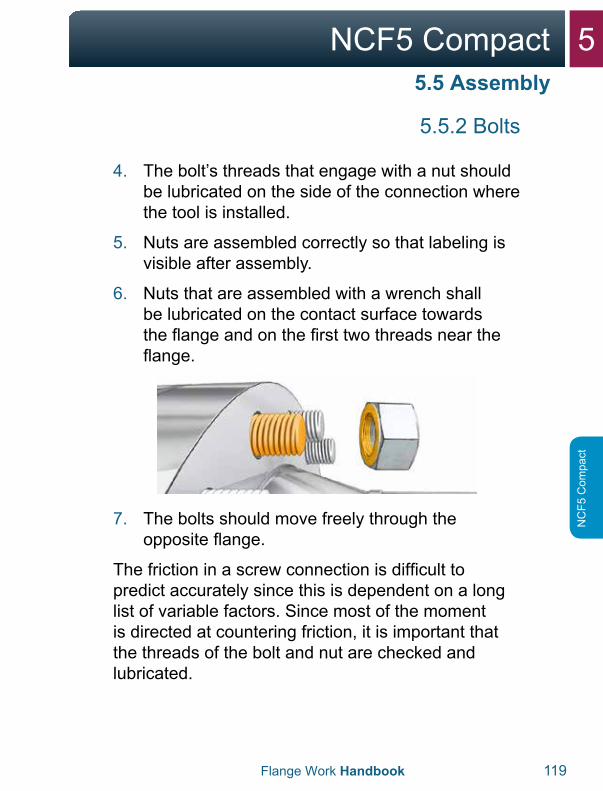
6. Nuts that are assembled with a wrench shallbe lubricated on the contact surface towardsthe flange and on the first two threads near theflange.
7. The bolts should move freely through theopposite flange.
The friction in a screw connection is difficult to predict accurately since this is dependent on a long list of variable factors. Since most of the moment is directed at countering friction, it is important that the threads of the bolt and nut are checked and lubricated.
5.5 Assembly
5 NCF5 Compact
120 Flange Work Handbook
NC
F5 Com
pact
Only approved tools should be used as listed in the bolting chart. If other tools are to be used, a new and approved bolting chart should be established.
If it is necessary to create special tools to tighten in tight spaces, this should be approved in agreement with the procedures of the operating company.
The following should be checked before the tool is used:
1. That the tool has valid calibration.2. That the tool and equipment are in an acceptable
condition before they are pressurized.3. That tools and equipment are used
in accordance with the supplier’srecommendations.
The following safety steps should be taken when the tool is in use:
1. Maintain a safe distance from the tool while thetool is pressurized.
2. Do not attempt to hold or adjust the tool when itis in operation.
3. Do not leave the work-site with a pressurizedtool.
4. Use a wire to secure loose tools with work atheights.
* See Appendix “Safety moments”.
5.6 Tightening
5NCF5 Compact
Flange Work Handbook 121
NC
F5 C
ompa
ct
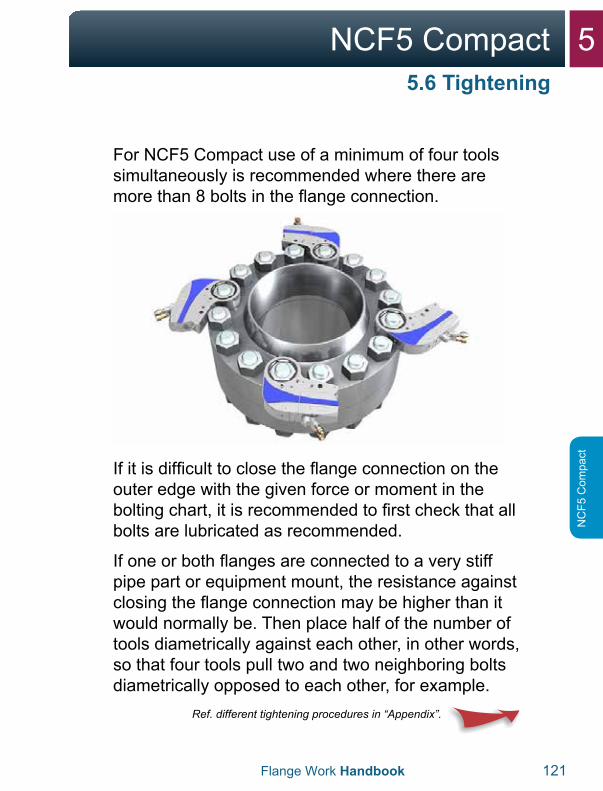
For NCF5 Compact use of a minimum of four tools simultaneously is recommended where there are more than 8 bolts in the flange connection.
If it is difficult to close the flange connection on the outer edge with the given force or moment in the bolting chart, it is recommended to first check that all bolts are lubricated as recommended.
If one or both flanges are connected to a very stiff pipe part or equipment mount, the resistance against closing the flange connection may be higher than it would normally be. Then place half of the number of tools diametrically against each other, in other words, so that four tools pull two and two neighboring bolts diametrically opposed to each other, for example.
Ref. different tightening procedures in “Appendix”.
5.6 Tightening
5 NCF5 Compact
122 Flange Work Handbook
NC
F5 Com
pact
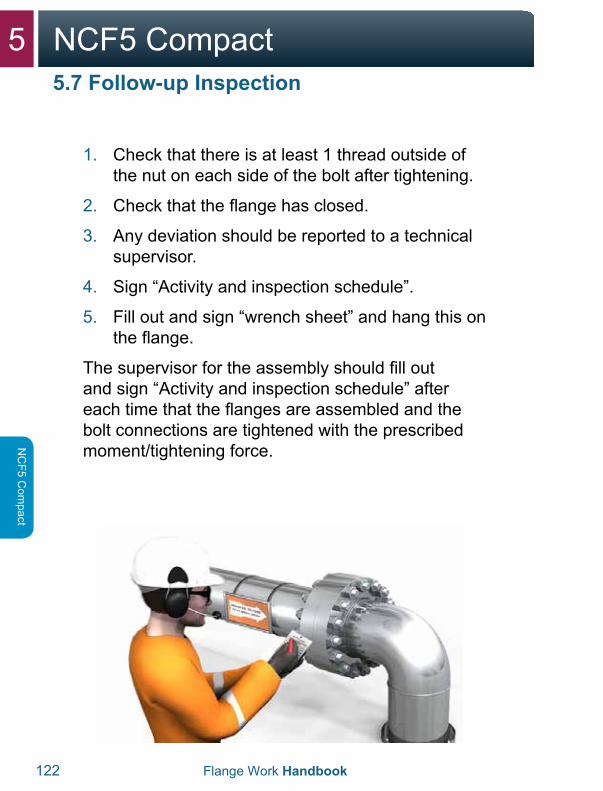
1. Check that there is at least 1 thread outside ofthe nut on each side of the bolt after tightening.
2. Check that the flange has closed.
3. Any deviation should be reported to a technicalsupervisor.
4. Sign “Activity and inspection schedule”.
5. Fill out and sign “wrench sheet” and hang this onthe flange.
The supervisor for the assembly should fill out and sign “Activity and inspection schedule” after each time that the flanges are assembled and the bolt connections are tightened with the prescribed moment/tightening force.
5.7 Follow-up Inspection
5NCF5 Compact
Flange Work Handbook 123
NC
F5 C
ompa
ct
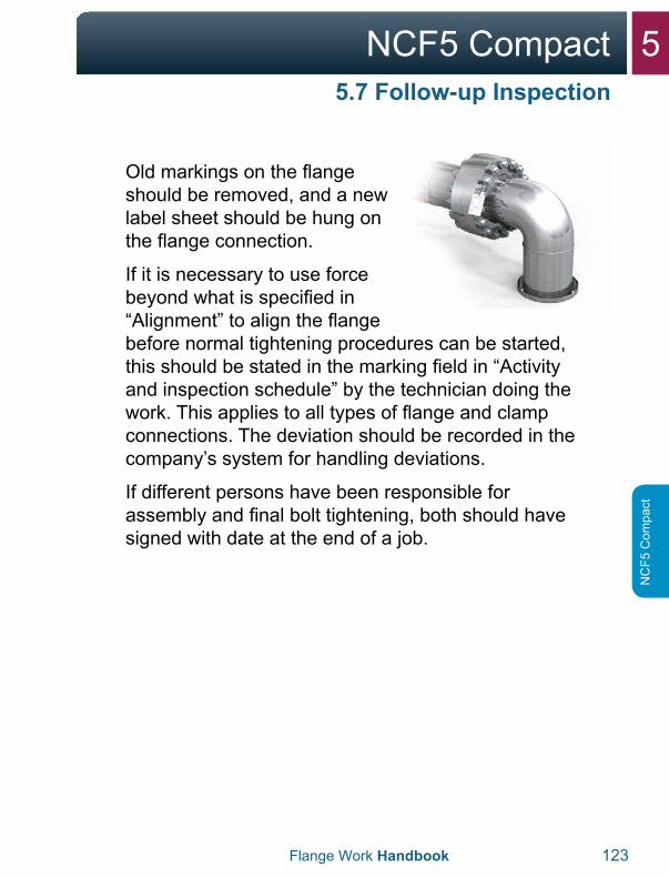
Old markings on the flange should be removed, and a new label sheet should be hung on the flange connection.
If it is necessary to use force beyond what is specified in “Alignment” to align the flange before normal tightening procedures can be started, this should be stated in the marking field in “Activity and inspection schedule” by the technician doing the work. This applies to all types of flange and clamp connections. The deviation should be recorded in the company’s system for handling deviations.
If different persons have been responsible for assembly and final bolt tightening, both should have signed with date at the end of a job.
5.7 Follow-up Inspection

6Clamp Connections
6Clamp Connections
6.1 Flange and Gasket Type 6B 126-127
6.2 Disassembly 128-135
6.3 Inspection 136
6.4 Alignment 137
6.5 Installation 138-141
6.6 Tightening 142-143
6.7 Follow-up Inspection 144-147
6 Clamp Connections
126 Flange Work Handbook
Clam
p C
onnections
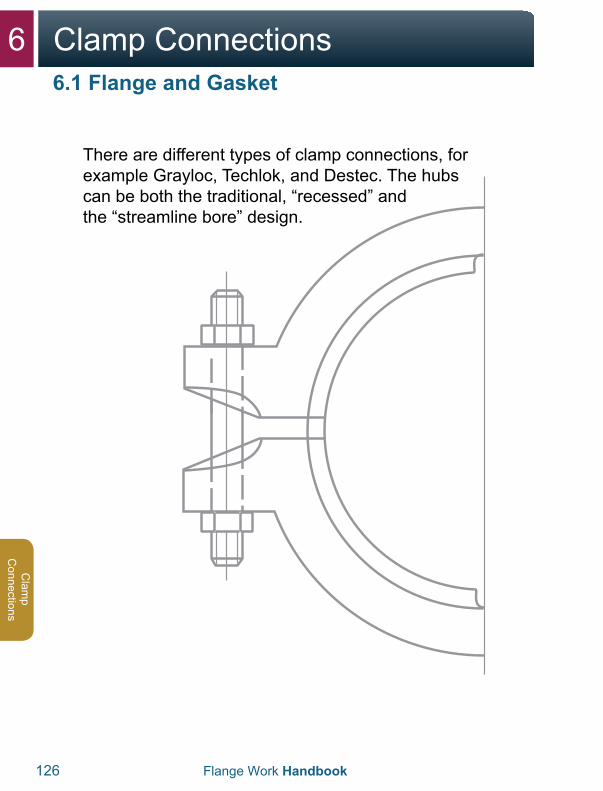
There are different types of clamp connections, for example Grayloc, Techlok, and Destec. The hubs can be both the traditional, “recessed” and the “streamline bore” design.
6.1 Flange and Gasket

6Clamp Connections
Flange Work Handbook 127
Cla
mp
Con
nect
ions
The pipe clamp’s design ensures that the sealing ring is clamped tight during assembly. The ring will be tight against the outer diameter against the hubs. The pressure from the media in the pipe will press the ring out and thereby provide better tightening the higher the pressure the application is exposed to.
For clamp connections, the sealing ring is normally exposed to the media, and it is especially important to check that the label matches the bolting table or the pipe specification.
6.1 Flange and Gasket
6 Clamp Connections
128 Flange Work Handbook
Clam
p C
onnections
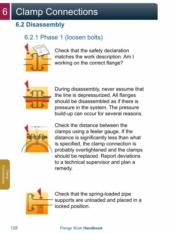
6.2.1 Phase 1 (loosen bolts)
Check that the safety declaration matches the work description. Am I working on the correct flange?
During disassembly, never assume that the line is depressurized. All flanges should be disassembled as if there is pressure in the system. The pressure build-up can occur for several reasons.
Check the distance between the clamps using a feeler gauge. If the distance is significantly less than what is specified, the clamp connection is probably overtightened and the clamps should be replaced. Report deviations to a technical supervisor and plan a remedy.
Check that the spring-loaded pipe supports are unloaded and placed in a locked position.
6.2 Disassembly
6Clamp Connections
Flange Work Handbook 129
Cla
mp
Con
nect
ions
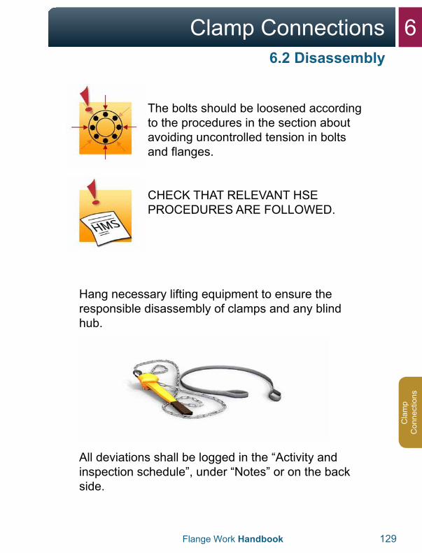
The bolts should be loosened according to the procedures in the section about avoiding uncontrolled tension in bolts and flanges.
CHECK THAT RELEVANT HSE PROCEDURES ARE FOLLOWED.
Hang necessary lifting equipment to ensure the responsible disassembly of clamps and any blind hub.
All deviations shall be logged in the “Activity and inspection schedule”, under “Notes” or on the back side.
6.2 Disassembly
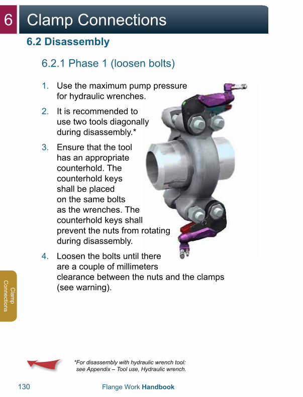
6 Clamp Connections
130 Flange Work Handbook
Clam
p C
onnections
6.2.1 Phase 1 (loosen bolts)
1. Use the maximum pump pressurefor hydraulic wrenches.
2. It is recommended touse two tools diagonallyduring disassembly.*
3. Ensure that the toolhas an appropriatecounterhold. Thecounterhold keysshall be placedon the same boltsas the wrenches. Thecounterhold keys shallprevent the nuts from rotatingduring disassembly.
4. Loosen the bolts until thereare a couple of millimetersclearance between the nuts and the clamps(see warning).
* For disassembly with hydraulic wrench tool:see Appendix – Tool use, Hydraulic wrench.
6.2 Disassembly
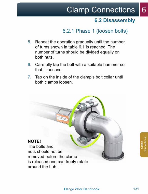
6Clamp Connections
Flange Work Handbook 131
Cla
mp
Con
nect
ions
6.2 Disassembly
6.2.1 Phase 1 (loosen bolts)
5. Repeat the operation gradually until the numberof turns shown in table 6.1 is reached. Thenumber of turns should be divided equally onboth nuts.
6. Carefully tap the bolt with a suitable hammer sothat it loosens.
7. Tap on the inside of the clamp’s bolt collar untilboth clamps loosen.
NOTE!The bolts and nuts should not be removed before the clamp is released and can freely rotate around the hub.
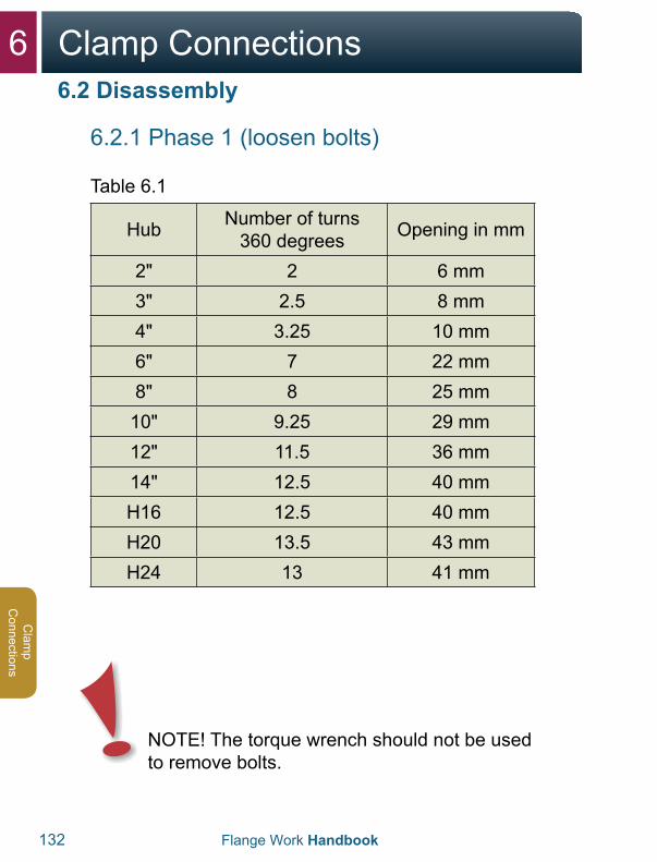
6 Clamp Connections
132 Flange Work Handbook
Clam
p C
onnections
6.2.1 Phase 1 (loosen bolts)
Table 6.1
Hub Number of turns 360 degrees Opening in mm
2" 2 6 mm3" 2.5 8 mm4" 3.25 10 mm6" 7 22 mm8" 8 25 mm
10" 9.25 29 mm12" 11.5 36 mm14" 12.5 40 mmH16 12.5 40 mmH20 13.5 43 mmH24 13 41 mm
NOTE! The torque wrench should not be used to remove bolts.
6.2 Disassembly
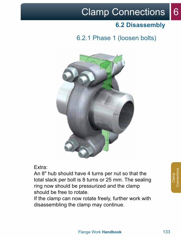
6Clamp Connections
Flange Work Handbook 133
Cla
mp
Con
nect
ions
6.2.1 Phase 1 (loosen bolts)
Extra:An 8" hub should have 4 turns per nut so that the total slack per bolt is 8 turns or 25 mm. The sealing ring now should be pressurized and the clamp should be free to rotate.If the clamp can now rotate freely, further work with disassembling the clamp may continue.
6.2 Disassembly
6 Clamp Connections
134 Flange Work Handbook
Clam
p C
onnections
6.2.2 Phase 2 (open connection)
6.2 Disassembly
WARNING:
If the clamp, after the number of turns is complete, cannot rotate freely around the hub, this indicates that there can be tension in the pipe system or that there is still pressure in the pipe. In this case, all further work should be stopped and a technical supervisor/system supervisor should be contacted.
Also be aware that any tension in the pipe system can be freed when someone tries to rotate the clamp.
There can be tension in the pipe that is first released when the sealing ring slips on one of the sides. Care should be shown during the removal of the clamps. It is recommended that you secure the pipe system in advance.
In cases where the sealing ring cannot be released when the clamps are removed, steps should be initiated to discharge the hub.
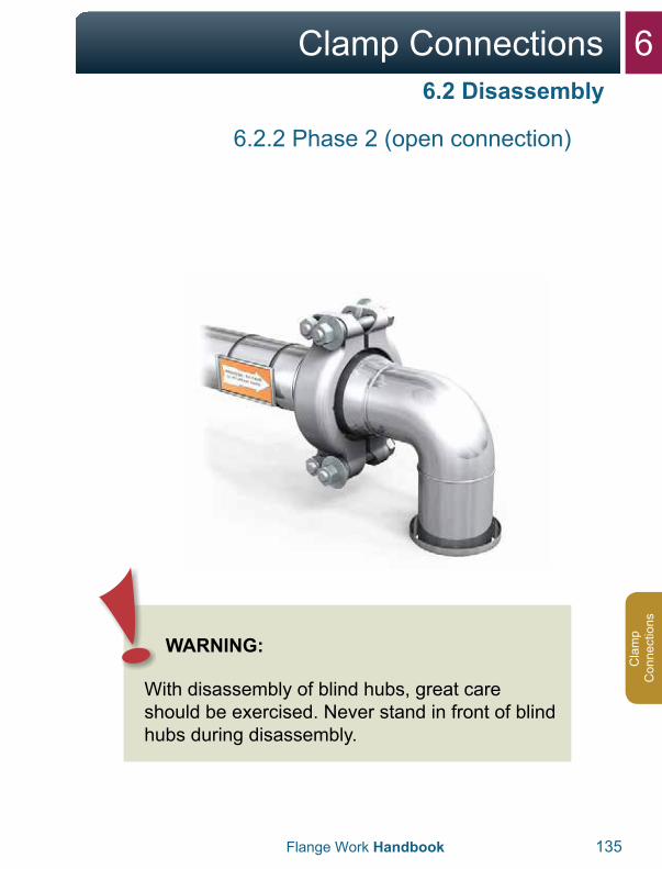
6Clamp Connections
Flange Work Handbook 135
Cla
mp
Con
nect
ions
6.2.2 Phase 2 (open connection)
6.2 Disassembly
WARNING:
With disassembly of blind hubs, great care should be exercised. Never stand in front of blind hubs during disassembly.
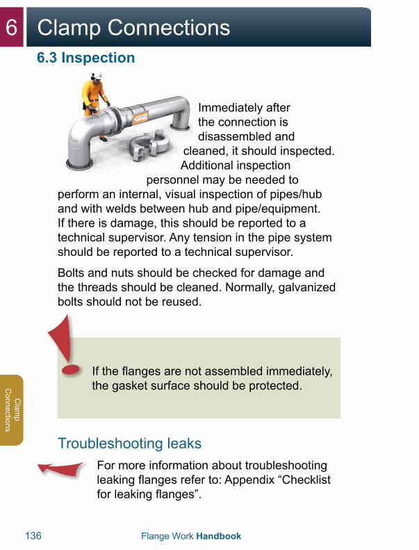
6 Clamp Connections
136 Flange Work Handbook
Clam
p C
onnections
Immediately after the connection is disassembled and
cleaned, it should inspected. Additional inspection
personnel may be needed to perform an internal, visual inspection of pipes/hub and with welds between hub and pipe/equipment. If there is damage, this should be reported to a technical supervisor. Any tension in the pipe system should be reported to a technical supervisor.
Bolts and nuts should be checked for damage and the threads should be cleaned. Normally, galvanized bolts should not be reused.
Troubleshooting leaks For more information about troubleshooting leaking flanges refer to: Appendix “Checklist for leaking flanges”.
6.3 Inspection
If the flanges are not assembled immediately, the gasket surface should be protected.

6Clamp Connections
Flange Work Handbook 137
Cla
mp
Con
nect
ions
The hubs shall be set up in parallel for assembly of sealing rings and clamps. The hubs should be set up so that the lips of the sealing ring enter the light gasket surface on both hubs, and guide the hubs together in the correct way during the tightening of the bolts in the clamps.
Never try to correct a bad setup using a clamp/bolt tightening alone. Use hoists or other approved tool. Relevant temporary alignment with the help of hoists, etc. should first be removed when the clamps are finally assembled. The alignment forces to be used should be evaluated and approved by a technical supervisor.
6.4 Alignment

6 Clamp Connections
138 Flange Work Handbook
Clam
p C
onnections
Before tightening flanges, be sure to thoroughly plan and prepare for the job in advance.
1. Seal surfaces on hubs should be checkedfor damage, corrosion and wear, and that theseal surface is free of coatings from paintingand preservative. The clamp’s contact surfaceagainst the nuts should also be free of any paintand preservative. Galvanizing or a thin layer withprimer is permitted.
2. Clean seal surfaces. Steel brushes or approvedemery paper may be used for this. Approvedsolvents and cloths may be used for finalcleaning.
3. Do the cleaning along the seal surface. Ensurethat the cleaning does not create radial tracks onthe seal surface. You should pay careful attentionto damage in a radial direction.
6.5 Assembly
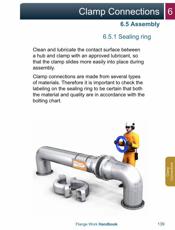
6Clamp Connections
Flange Work Handbook 139
Cla
mp
Con
nect
ions
6.5.1 Sealing ring
Clean and lubricate the contact surface between a hub and clamp with an approved lubricant, so that the clamp slides more easily into place during assembly.
Clamp connections are made from several types of materials. Therefore it is important to check the labeling on the sealing ring to be certain that both the material and quality are in accordance with the bolting chart.
6.5 Assembly
6 Clamp Connections
140 Flange Work Handbook
Clam
p C
onnections
6.5.1 Sealing ring
1. Opening between the hubs should be larger thanthe thickness of the sealing ring so that this is notdamaged during assembly.
2. A new sealing ring should always cover theclamp connections that have been opened.
3. Check that you have the correct sealing ringaccording to the table and that it is free ofdamage. The ring’s size and material quality ismarked on the ring.
4. Check that the ring sits correctly. It should beable to “rock” when it is placed in the hub. Checkagainst both the hubs! It is also important tocheck that the sealing ring’s collar lies parallel tothe hub. The manufacturer of the hub may havecreated a table for how much the ring should beable to rock (Stand-off). Check this.
5. The sealing rings for clamp connections thatare covered with Teflon (PTFE) should not belubricated. In cases where the rings are notTeflon-coated, these are lubricated with a thincoating of Vaseline or thin machine oil.
6.5 Assembly
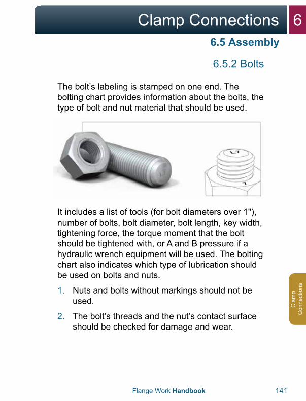
6Clamp Connections
Flange Work Handbook 141
Cla
mp
Con
nect
ions
6.5.2 Bolts
The bolt’s labeling is stamped on one end. The bolting chart provides information about the bolts, the type of bolt and nut material that should be used.
It includes a list of tools (for bolt diameters over 1"), number of bolts, bolt diameter, bolt length, key width, tightening force, the torque moment that the bolt should be tightened with, or A and B pressure if a hydraulic wrench equipment will be used. The bolting chart also indicates which type of lubrication should be used on bolts and nuts.
1. Nuts and bolts without markings should not beused.
2. The bolt’s threads and the nut’s contact surfaceshould be checked for damage and wear.
6.5 Assembly
6 Clamp Connections
142 Flange Work Handbook
Clam
p C
onnections
1. Always use the lubricant that is specified in thebolting chart.
2. The bolt should not be lubricated before it isassembled in the clamp.
3. The bolt’s threads that engage with a nut shouldbe lubricated on the side where the tool isinstalled.
4. Nuts are assembled correctly so that labeling isvisible after assembly.
5. Nuts that are assembled with a wrench shallbe lubricated on the contact surface towardsthe flange and on the first two threads near theflange.
6. The bolts should move freely through theopposite clamp.
The friction in a screw connection is difficult to predict accurately since this is dependent on a long list of variable factors. Since most of the moment is directed at countering friction, it is important that the threads of the bolt and nut are checked and lubricated.
6.6 Tightening
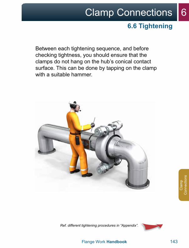
6Clamp Connections
Flange Work Handbook 143
Cla
mp
Con
nect
ions
Between each tightening sequence, and before checking tightness, you should ensure that the clamps do not hang on the hub’s conical contact surface. This can be done by tapping on the clamp with a suitable hammer.
Ref. different tightening procedures in “Appendix”.
6.6 Tightening
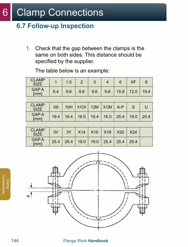
6 Clamp Connections
144 Flange Work Handbook
Clam
p C
onnections
1. Check that the gap between the clamps is thesame on both sides. This distance should bespecified by the supplier.
The table below is an example:CLAMP
SIZE 1 1.5 2 3 4 6 XF 8
GAP A [mm] 6.4 9.6 9.6 9.6 9.6 15.8 12.0 19.4
CLAMP SIZE X8 10H X1CH 12M X12M A-P S U
GAP A [mm] 19.4 19.4 16.0 19.4 16.0 25.4 19.0 25.4
CLAMP SIZE 3V 3Y X14 X16 X18 X20 X24
GAP A [mm] 25.4 25.4 19.0 19.0 25.4 25.4 25.4
6.7 Follow-up Inspection
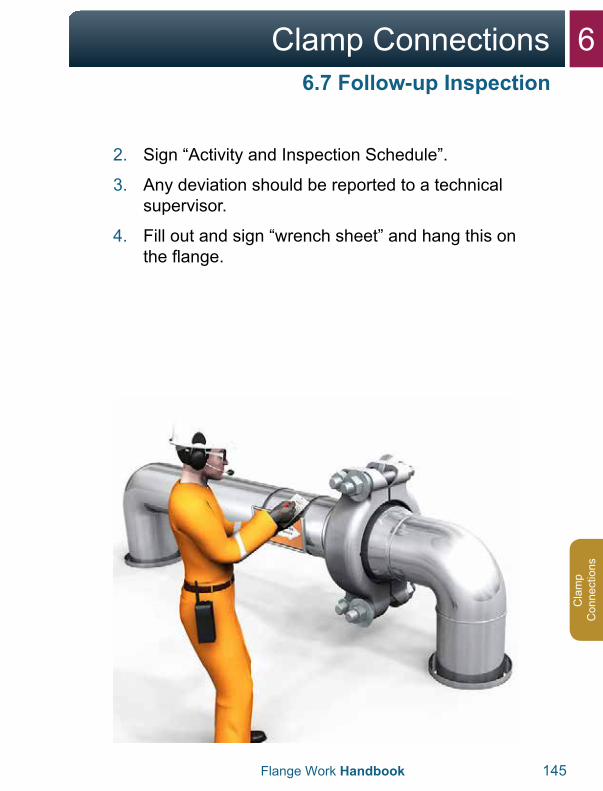
6Clamp Connections
Flange Work Handbook 145
Cla
mp
Con
nect
ions
2. Sign “Activity and Inspection Schedule”.
3. Any deviation should be reported to a technicalsupervisor.
4. Fill out and sign “wrench sheet” and hang this onthe flange.
6.7 Follow-up Inspection
6 Clamp Connections
146 Flange Work Handbook
Clam
p C
onnections
The supervisor for assembly should fill out and sign “Activity and inspection schedule” after each time that the hubs are assembled and the bolt connections are tightened with the prescribed moment/tightening force.
5. Old markings should be removed, and a newlabel sheet should be hung on the clampconnection.
Check that the support ring on the sealing ring has contact with both the hubs. If there is a gap, the connection is not correctly assembled. Check that the distance between the clamps is correct in relation to the table from a supplier.
6. If it is necessary to use abnormally large forcesto correct the hubs before normal tighteningprocedures can be started, this should be statedin the marking field in “Activity and inspectionschedule” by the technician doing the work. Thedeviation should be recorded in the company’ssystem for handling deviations.
7. If different persons have been responsible forassembly and final bolt tightening, both shouldhave signed with date at the end of a job.
6.7 Follow-up Inspection
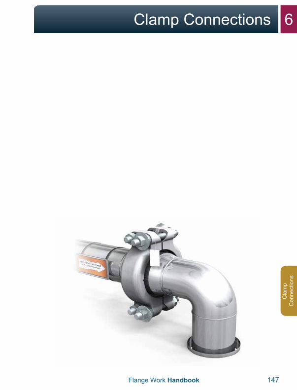
6Clamp Connections
Flange Work Handbook 147
Cla
mp
Con
nect
ions

7Appendix
7Appendix
150-151
152-163
164-166
168-171
172-173
174-200
201-203
204-205
7.1 Safety Moment, locking pin/locking disk
7.2 Tool Use
7.3 Bolt Tables
7.4 Tables ASME RTJ, gap
7.5 Tables API 6A Type 6B, gap
7.6 Spring Supports
7.7 Checklist for Leaking Flanges
7.8 Example of Tightening Sheet
7.9 Example of Activity Inspection Schedule 206-207
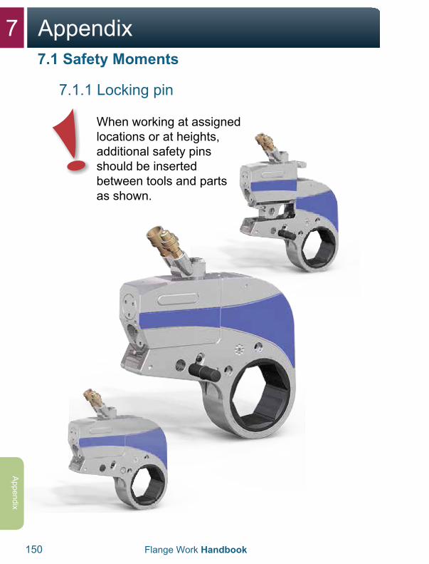
7 Appendix
150 Flange Work Handbook
Appendix
7.1.1 Locking pin
When working at assigned locations or at heights, additional safety pins should be inserted between tools and parts as shown.
7.1 Safety Moments

7Appendix
Flange Work Handbook 151
App
endi
x
7.1.2 Locking disk
When working on flanges, where there is a need to grip or hold onto the tool, a locking disk should be installed to prevent clamp damage. For example where the tools have to be installed on the underside of the flange.
7.1 Safety Moments
7 Appendix
152 Flange Work Handbook
Appendix
7.2.1 Loosen bolts, hydraulic wrench
1. Use the maximum pump pressure for hydraulicwrenches. It is recommended that you use fourtools during disassembly.
2. Ensure that the tool has an appropriatecounterhold.
3. The counterhold keys shall be placed on thesame bolts as the wrenches.
4. The counterhold keys shall prevent the nuts fromrotating during disassembly.
Install the equipment and check it as described for tightening. Set the pump for maximum pressure.
7.2 Tool Use
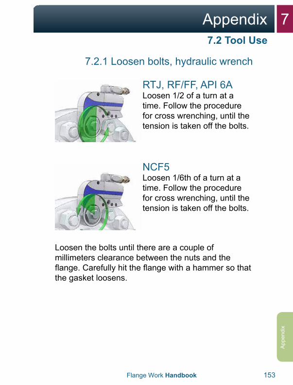
7Appendix
Flange Work Handbook 153
App
endi
x
7.2.1 Loosen bolts, hydraulic wrench
RTJ, RF/FF, API 6ALoosen 1/2 of a turn at a time. Follow the procedure for cross wrenching, until the tension is taken off the bolts.
NCF5Loosen 1/6th of a turn at a time. Follow the procedure for cross wrenching, until the tension is taken off the bolts.
Loosen the bolts until there are a couple of millimeters clearance between the nuts and the flange. Carefully hit the flange with a hammer so that the gasket loosens.
7.2 Tool Use
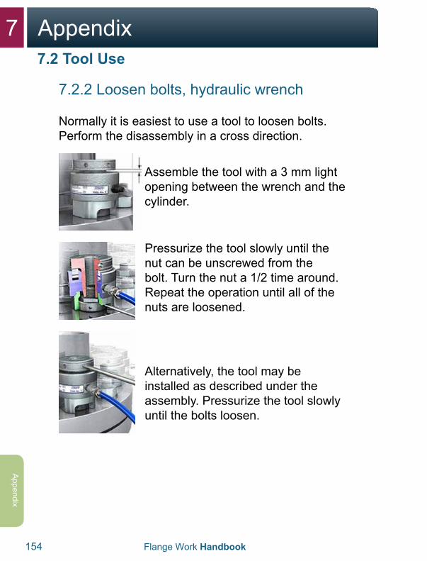
7 Appendix
154
Appendix
7.2.2 Loosen bolts, hydraulic wrench
Normally it is easiest to use a tool to loosen bolts. Perform the disassembly in a cross direction.
Assemble the tool with a 3 mm light opening between the wrench and the cylinder.
Pressurize the tool slowly until the nut can be unscrewed from the bolt. Turn the nut a 1/2 time around. Repeat the operation until all of the nuts are loosened.
Alternatively, the tool may be installed as described under the assembly. Pressurize the tool slowly until the bolts loosen.
Flange Work Handbook
7.2 Tool Use

7Appendix
Flange Work Handbook 155
App
endi
x
7.2.3 Tighten bolts, hand tool
In accordance with NORSOK L-004, torque wrenches may be used for bolt sizes up to and including 1". Check that the tool’s calibration is valid with respect to EN ISO/IEC 6789/17025.
Use a torque wrench if a hydraulic tool isn’t appropriate. To avoid deformation in the spring, the key should always be reset after use – this does not apply to Stahlwille keys as shown. Follow guidelines from the supplier of the torque wrench.
7.2 Tool Use
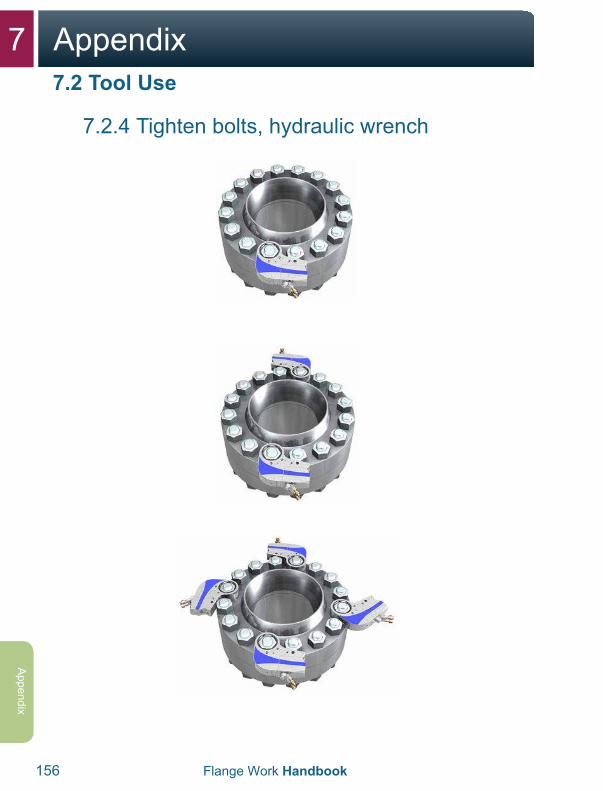
7 Appendix
156 Flange Work Handbook
Appendix
7.2.4 Tighten bolts, hydraulic wrench
7.2 Tool Use
7Appendix
Flange Work Handbook 157
App
endi
x
7.2.4 Tighten bolts, hydraulic wrench
Tightening procedure with 1 tool1. 1 revolution across with 30% of the given moment.2. 1 revolution across with 60% of the given moment.3. 2 revolutions across with 100% of the given
moment.4. After the last tightening, all bolts should be
checked with full moment.5. Do checks in a clockwise
direction.
Tightening procedure with 2 tools1. 1 revolution across with 50% of the given
moment.2. 2 revolutions across with 100% of the given
moment.3. After the last tightening, all bolts should be
checked with full moment.4. Do checks in a clockwise direction.
Tightening procedure with 4 tools1. Tighten all bolts with the given moment in the
bolting chart 2 times.2. Check that the tools are placed crosswise at all
times.3. After the last tightening, all bolts should be
checked with full moment.4. Do checks in a clockwise direction.
7.2 Tool Use
This procedure also applies for use of a torque wrench.
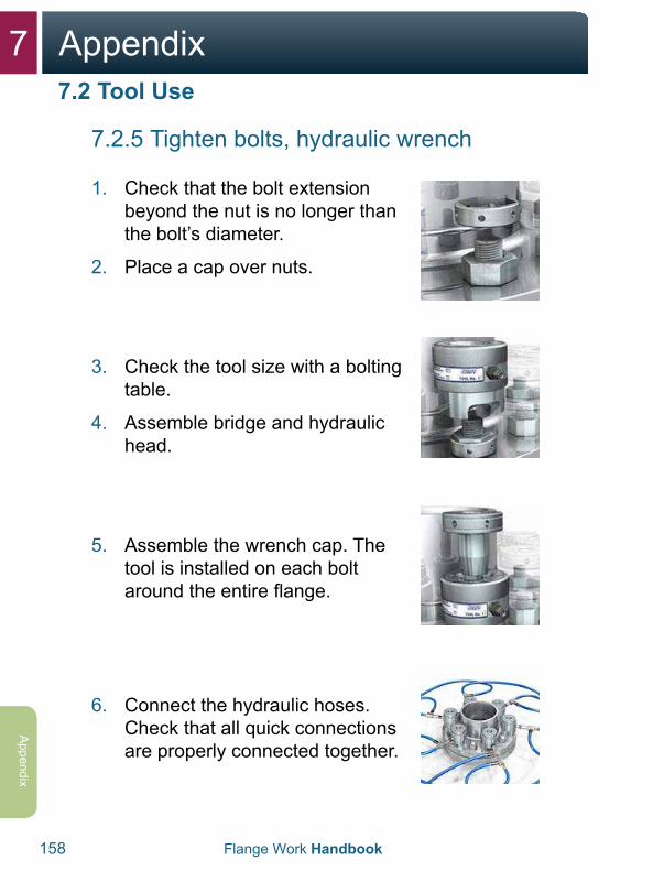
7 Appendix
158 Flange Work Handbook
Appendix
7.2.5 Tighten bolts, hydraulic wrench
1. Check that the bolt extensionbeyond the nut is no longer thanthe bolt’s diameter.
2. Place a cap over nuts.
3. Check the tool size with a boltingtable.
4. Assemble bridge and hydraulichead.
5. Assemble the wrench cap. Thetool is installed on each boltaround the entire flange.
6. Connect the hydraulic hoses.Check that all quick connectionsare properly connected together.
7.2 Tool Use
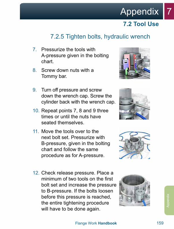
7Appendix
Flange Work Handbook 159
App
endi
x
7.2.5 Tighten bolts, hydraulic wrench
7. Pressurize the tools withA-pressure given in the boltingchart.
8. Screw down nuts with aTommy bar.
9. Turn off pressure and screwdown the wrench cap. Screw thecylinder back with the wrench cap.
10. Repeat points 7, 8 and 9 threetimes or until the nuts haveseated themselves.
11. Move the tools over to thenext bolt set. Pressurize withB-pressure, given in the boltingchart and follow the sameprocedure as for A-pressure.
12. Check release pressure. Place aminimum of two tools on the firstbolt set and increase the pressureto B-pressure. If the bolts loosenbefore this pressure is reached,the entire tightening procedurewill have to be done again.
7.2 Tool Use
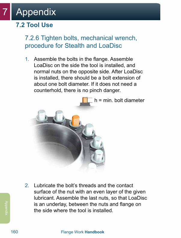
7 Appendix
160 Flange Work Handbook
Appendix
7.2.6 Tighten bolts, mechanical wrench, procedure for Stealth and LoaDisc
1. Assemble the bolts in the flange. AssembleLoaDisc on the side the tool is installed, andnormal nuts on the opposite side. After LoaDiscis installed, there should be a bolt extension ofabout one bolt diameter. If it does not need acounterhold, there is no pinch danger.
h = min. bolt diameter
2. Lubricate the bolt’s threads and the contactsurface of the nut with an even layer of the givenlubricant. Assemble the last nuts, so that LoaDiscis an underlay, between the nuts and flange onthe side where the tool is installed.
7.2 Tool Use
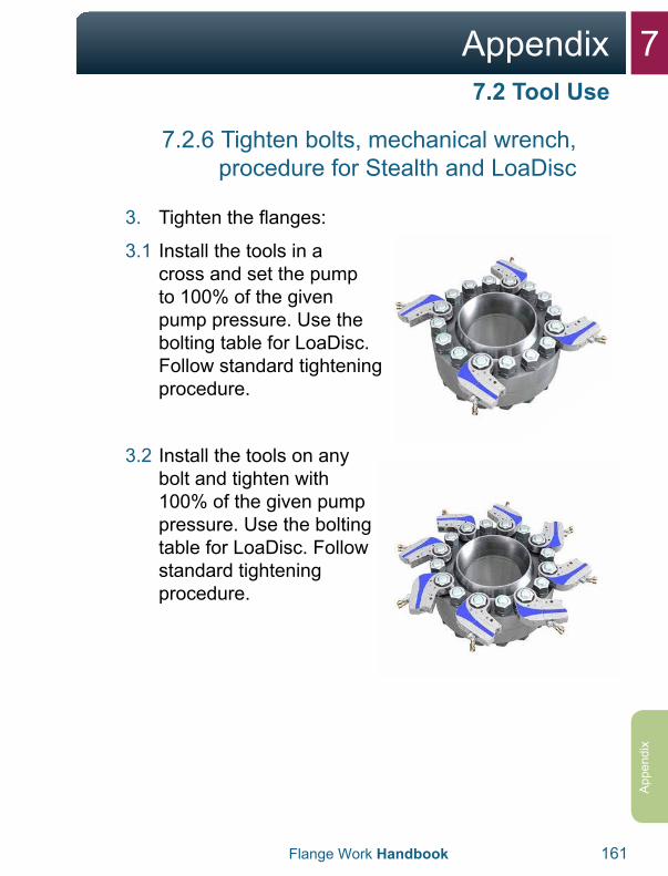
7Appendix
Flange Work Handbook 161
App
endi
x
7.2.6 Tighten bolts, mechanical wrench, procedure for Stealth and LoaDisc
3. Tighten the flanges:
3.1 Install the tools in across and set the pump to 100% of the given pump pressure. Use the bolting table for LoaDisc. Follow standard tightening procedure.
3.2 Install the tools on any bolt and tighten with 100% of the given pump pressure. Use the bolting table for LoaDisc. Follow standard tightening procedure.
7.2 Tool Use
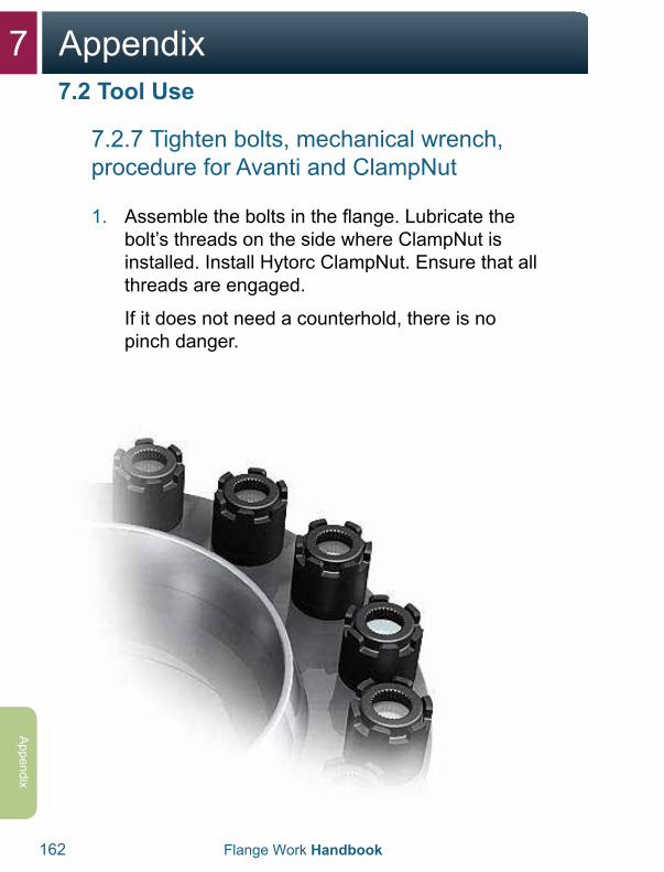
7 Appendix
162 Flange Work Handbook
Appendix
7.2.7 Tighten bolts, mechanical wrench, procedure for Avanti and ClampNut
1. Assemble the bolts in the flange. Lubricate thebolt’s threads on the side where ClampNut isinstalled. Install Hytorc ClampNut. Ensure that allthreads are engaged.
If it does not need a counterhold, there is nopinch danger.
7.2 Tool Use
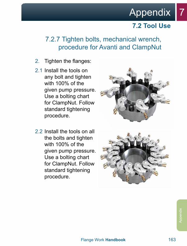
7Appendix
Flange Work Handbook 163
App
endi
x
7.2.7 Tighten bolts, mechanical wrench, procedure for Avanti and ClampNut
2. Tighten the flanges:
2.1 Install the tools onany bolt and tighten with 100% of the given pump pressure. Use a bolting chart for ClampNut. Follow standard tightening procedure.
2.2 Install the tools on all the bolts and tighten with 100% of the given pump pressure. Use a bolting chart for ClampNut. Follow standard tightening procedure.
7.2 Tool Use
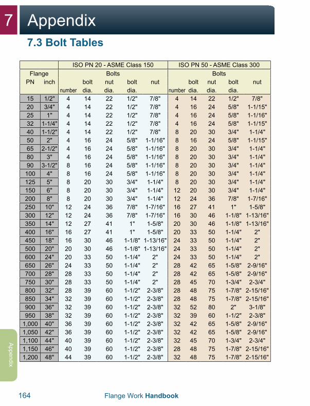
7 Appendix
164 Flange Work Handbook
Appendix
ISO PN 20 - ASME Class 150 ISO PN 50 - ASME Class 300Flange Bolts Bolts
PN inch bolt nut bolt nut bolt nut bolt nutnumber dia. dia. dia. number dia. dia. dia.
15 1/2" 4 14 22 1/2" 7/8" 4 14 22 1/2" 7/8"20 3/4" 4 14 22 1/2" 7/8" 4 16 24 5/8" 1-1/15"25 1" 4 14 22 1/2" 7/8" 4 16 24 5/8" 1-1/16"32 1-1/4" 4 14 22 1/2" 7/8" 4 16 24 5/8" 1-1/15"40 1-1/2" 4 14 22 1/2" 7/8" 8 20 30 3/4" 1-1/4"50 2" 4 16 24 5/8" 1-1/16" 8 16 24 5/8" 1-1/15"65 2-1/2" 4 16 24 5/8" 1-1/16" 8 20 30 3/4" 1-1/4"80 3" 4 16 24 5/8" 1-1/16" 8 20 30 3/4" 1-1/4"90 3-1/2" 8 16 24 5/8" 1-1/16" 8 20 30 3/4" 1-1/4"100 4" 8 16 24 5/8" 1-1/16" 8 20 30 3/4" 1-1/4"125 5" 8 20 30 3/4" 1-1/4" 8 20 30 3/4" 1-1/4"150 6" 8 20 30 3/4" 1-1/4" 12 20 30 3/4" 1-1/4"200 8" 8 20 30 3/4" 1-1/4" 12 24 36 7/8" 1-7/16"250 10" 12 24 36 7/8" 1-7/16" 16 27 41 1" 1-5/8"300 12" 12 24 36 7/8" 1-7/16" 16 30 46 1-1/8" 1-13/16"350 14" 12 27 41 1" 1-5/8" 20 30 46 1-1/8" 1-13/16"400 16" 16 27 41 1" 1-5/8" 20 33 50 1-1/4" 2"450 18" 16 30 46 1-1/8" 1-13/16" 24 33 50 1-1/4" 2"500 20" 20 30 46 1-1/8" 1-13/16" 24 33 50 1-1/4" 2"600 24" 20 33 50 1-1/4" 2" 24 33 50 1-1/4" 2"650 26" 24 33 50 1-1/4" 2" 28 42 65 1-5/8" 2-9/16"700 28" 28 33 50 1-1/4" 2" 28 42 65 1-5/8" 2-9/16"750 30" 28 33 50 1-1/4" 2" 28 45 70 1-3/4" 2-3/4"800 32" 28 39 60 1-1/2" 2-3/8" 28 48 75 1-7/8" 2-15/16"850 34" 32 39 60 1-1/2" 2-3/8" 28 48 75 1-7/8" 2-15/16"900 36" 32 39 60 1-1/2" 2-3/8" 32 52 80 2" 3-1/8"950 38" 32 39 60 1-1/2" 2-3/8" 32 39 60 1-1/2" 2-3/8"
1,000 40" 36 39 60 1-1/2" 2-3/8" 32 42 65 1-5/8" 2-9/16"1,050 42" 36 39 60 1-1/2" 2-3/8" 32 42 65 1-5/8" 2-9/16"1,100 44" 40 39 60 1-1/2" 2-3/8" 32 45 70 1-3/4" 2-3/4"1,150 46" 40 39 60 1-1/2" 2-3/8" 28 48 75 1-7/8" 2-15/16"1,200 48" 44 39 60 1-1/2" 2-3/8" 32 48 75 1-7/8" 2-15/16"
7.3 Bolt Tables
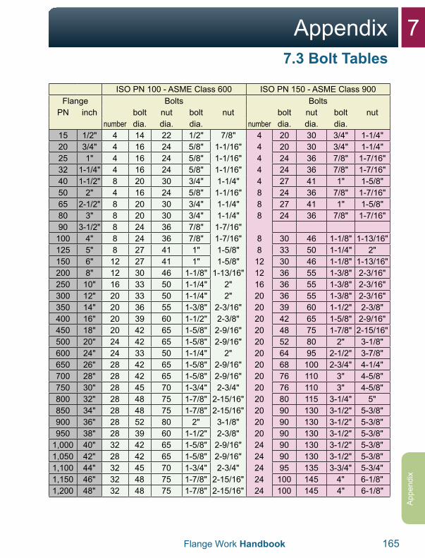
7Appendix
Flange Work Handbook 165
App
endi
x
ISO PN 100 - ASME Class 600 ISO PN 150 - ASME Class 900Flange Bolts Bolts
PN inch bolt nut bolt nut bolt nut bolt nutnumber dia. dia. dia. number dia. dia. dia.
15 1/2" 4 14 22 1/2" 7/8" 4 20 30 3/4" 1-1/4"20 3/4" 4 16 24 5/8" 1-1/16" 4 20 30 3/4" 1-1/4"25 1" 4 16 24 5/8" 1-1/16" 4 24 36 7/8" 1-7/16"32 1-1/4" 4 16 24 5/8" 1-1/16" 4 24 36 7/8" 1-7/16"40 1-1/2" 8 20 30 3/4" 1-1/4" 4 27 41 1" 1-5/8"50 2" 4 16 24 5/8" 1-1/16" 8 24 36 7/8" 1-7/16"65 2-1/2" 8 20 30 3/4" 1-1/4" 8 27 41 1" 1-5/8"80 3" 8 20 30 3/4" 1-1/4" 8 24 36 7/8" 1-7/16"90 3-1/2" 8 24 36 7/8" 1-7/16"100 4" 8 24 36 7/8" 1-7/16" 8 30 46 1-1/8" 1-13/16"125 5" 8 27 41 1" 1-5/8" 8 33 50 1-1/4" 2"150 6" 12 27 41 1" 1-5/8" 12 30 46 1-1/8" 1-13/16"200 8" 12 30 46 1-1/8" 1-13/16" 12 36 55 1-3/8" 2-3/16"250 10" 16 33 50 1-1/4" 2" 16 36 55 1-3/8" 2-3/16"300 12" 20 33 50 1-1/4" 2" 20 36 55 1-3/8" 2-3/16"350 14" 20 36 55 1-3/8" 2-3/16" 20 39 60 1-1/2" 2-3/8"400 16" 20 39 60 1-1/2" 2-3/8" 20 42 65 1-5/8" 2-9/16"450 18" 20 42 65 1-5/8" 2-9/16" 20 48 75 1-7/8" 2-15/16"500 20" 24 42 65 1-5/8" 2-9/16" 20 52 80 2" 3-1/8"600 24" 24 33 50 1-1/4" 2" 20 64 95 2-1/2" 3-7/8"650 26" 28 42 65 1-5/8" 2-9/16" 20 68 100 2-3/4" 4-1/4"700 28" 28 42 65 1-5/8" 2-9/16" 20 76 110 3" 4-5/8"750 30" 28 45 70 1-3/4" 2-3/4" 20 76 110 3" 4-5/8"800 32" 28 48 75 1-7/8" 2-15/16" 20 80 115 3-1/4" 5"850 34" 28 48 75 1-7/8" 2-15/16" 20 90 130 3-1/2" 5-3/8"900 36" 28 52 80 2" 3-1/8" 20 90 130 3-1/2" 5-3/8"950 38" 28 39 60 1-1/2" 2-3/8" 20 90 130 3-1/2" 5-3/8"
1,000 40" 32 42 65 1-5/8" 2-9/16" 24 90 130 3-1/2" 5-3/8"1,050 42" 28 42 65 1-5/8" 2-9/16" 24 90 130 3-1/2" 5-3/8"1,100 44" 32 45 70 1-3/4" 2-3/4" 24 95 135 3-3/4" 5-3/4"1,150 46" 32 48 75 1-7/8" 2-15/16" 24 100 145 4" 6-1/8"1,200 48" 32 48 75 1-7/8" 2-15/16" 24 100 145 4" 6-1/8"
7.3 Bolt Tables
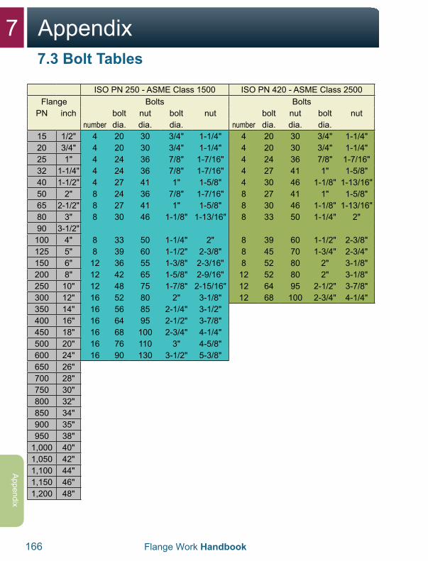
7 Appendix
166 Flange Work Handbook
Appendix
ISO PN 250 - ASME Class 1500 ISO PN 420 - ASME Class 2500Flange Bolts Bolts
PN inch bolt nut bolt nut bolt nut bolt nutnumber dia. dia. dia. number dia. dia. dia.
15 1/2" 4 20 30 3/4" 1-1/4" 4 20 30 3/4" 1-1/4"20 3/4" 4 20 30 3/4" 1-1/4" 4 20 30 3/4" 1-1/4"25 1" 4 24 36 7/8" 1-7/16" 4 24 36 7/8" 1-7/16"32 1-1/4" 4 24 36 7/8" 1-7/16" 4 27 41 1" 1-5/8"40 1-1/2" 4 27 41 1" 1-5/8" 4 30 46 1-1/8" 1-13/16"50 2" 8 24 36 7/8" 1-7/16" 8 27 41 1" 1-5/8"65 2-1/2" 8 27 41 1" 1-5/8" 8 30 46 1-1/8" 1-13/16"80 3" 8 30 46 1-1/8" 1-13/16" 8 33 50 1-1/4" 2"90 3-1/2"
100 4" 8 33 50 1-1/4" 2" 8 39 60 1-1/2" 2-3/8"125 5" 8 39 60 1-1/2" 2-3/8" 8 45 70 1-3/4" 2-3/4"150 6" 12 36 55 1-3/8" 2-3/16" 8 52 80 2" 3-1/8"200 8" 12 42 65 1-5/8" 2-9/16" 12 52 80 2" 3-1/8"250 10" 12 48 75 1-7/8" 2-15/16" 12 64 95 2-1/2" 3-7/8"300 12" 16 52 80 2" 3-1/8" 12 68 100 2-3/4" 4-1/4"350 14" 16 56 85 2-1/4" 3-1/2"400 16" 16 64 95 2-1/2" 3-7/8"450 18" 16 68 100 2-3/4" 4-1/4"500 20" 16 76 110 3" 4-5/8"600 24" 16 90 130 3-1/2" 5-3/8"650 26"700 28"750 30"800 32"850 34"900 35"950 38"
1,000 40"1,050 42"1,100 44"1,150 46"1,200 48"
7.3 Bolt Tables
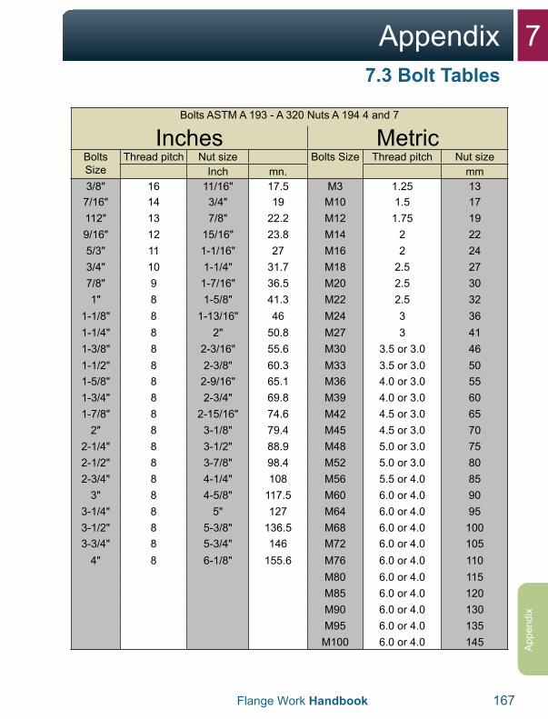
7Appendix
Flange Work Handbook 167
App
endi
x
Bolts ASTM A 193 - A 320 Nuts A 194 4 and 7
Inches MetricBolts Size
Thread pitch Nut size Bolts Size Thread pitch Nut sizeInch mn. mm
3/8" 16 11/16" 17.5 M3 1.25 137/16" 14 3/4" 19 M10 1.5 17112" 13 7/8" 22.2 M12 1.75 199/16" 12 15/16" 23.8 M14 2 225/3" 11 1-1/16" 27 M16 2 243/4" 10 1-1/4" 31.7 M18 2.5 277/8" 9 1-7/16" 36.5 M20 2.5 301" 8 1-5/8" 41.3 M22 2.5 32
1-1/8" 8 1-13/16" 46 M24 3 361-1/4" 8 2" 50.8 M27 3 411-3/8" 8 2-3/16" 55.6 M30 3.5 or 3.0 461-1/2" 8 2-3/8" 60.3 M33 3.5 or 3.0 501-5/8" 8 2-9/16" 65.1 M36 4.0 or 3.0 551-3/4" 8 2-3/4" 69.8 M39 4.0 or 3.0 601-7/8" 8 2-15/16" 74.6 M42 4.5 or 3.0 65
2" 8 3-1/8" 79.4 M45 4.5 or 3.0 702-1/4" 8 3-1/2" 88.9 M48 5.0 or 3.0 752-1/2" 8 3-7/8" 98.4 M52 5.0 or 3.0 802-3/4" 8 4-1/4" 108 M56 5.5 or 4.0 85
3" 8 4-5/8" 117.5 M60 6.0 or 4.0 903-1/4" 8 5" 127 M64 6.0 or 4.0 953-1/2" 8 5-3/8" 136.5 M68 6.0 or 4.0 1003-3/4" 8 5-3/4" 146 M72 6.0 or 4.0 105
4" 8 6-1/8" 155.6 M76 6.0 or 4.0 110M80 6.0 or 4.0 115M85 6.0 or 4.0 120M90 6.0 or 4.0 130M95 6.0 or 4.0 135
M100 6.0 or 4.0 145
7.3 Bolt Tables
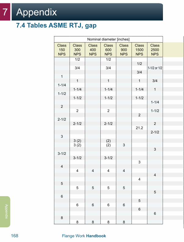
7 Appendix
168 Flange Work Handbook
Appendix
Approximate distance between flanges inside with a sealing ring [mm]
Class 150
Class 300
Class 400
Class 600
Class 900
Class 1500
Class 2500
3 34
4 4 4
44
4 4 4 44
4 4 4 44
4 4 43
46 5 3
34
6 5 33
34
6 5 43
46 5
34
6 6 5 44
34
6 6 5 44
43
6 6 5 43
44
6 6 5 4
Nominal diameter [inches]
Class 150 NPS
Class 300 NPS
Class 400 NPS
Class 600 NPS
Class 900 NPS
Class 1500 NPS
Class 2500 NPS
1/2 1/21/2
3/4 3/4 1-1/2 or 1/23/4
11 1 1 3/4
1-1/41-1/4 1-1/4 1-1/4 1
1-1/21-1/2 1-1/2 1-1/2
1-1/42
2 2 1-1/22
2-1/22-1/2 2-1/2 2
21.22-1/2
33 (2) (2)3 (2) (2) 3
33-1/2
3-1/2 3-1/23
44 4 4 4
44
55 5 5 5
56
56 6 6 6
66
88 8 8 8
7.4 Tables ASME RTJ, gap
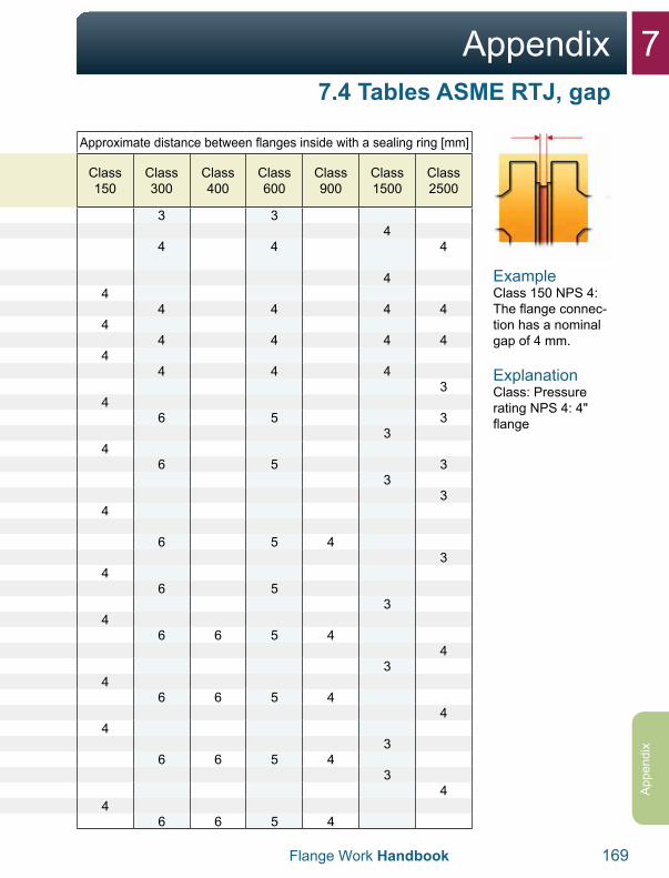
7Appendix
Flange Work Handbook 169
App
endi
x
Approximate distance between flanges inside with a sealing ring [mm]
Class 150
Class 300
Class 400
Class 600
Class 900
Class 1500
Class 2500
3 34
4 4 4
44
4 4 4 44
4 4 4 44
4 4 43
46 5 3
34
6 5 33
34
6 5 43
46 5
34
6 6 5 44
34
6 6 5 44
43
6 6 5 43
44
6 6 5 4
7.4 Tables ASME RTJ, gap
ExampleClass 150 NPS 4: The flange connec-tion has a nominal gap of 4 mm.
ExplanationClass: Pressure rating NPS 4: 4" flange
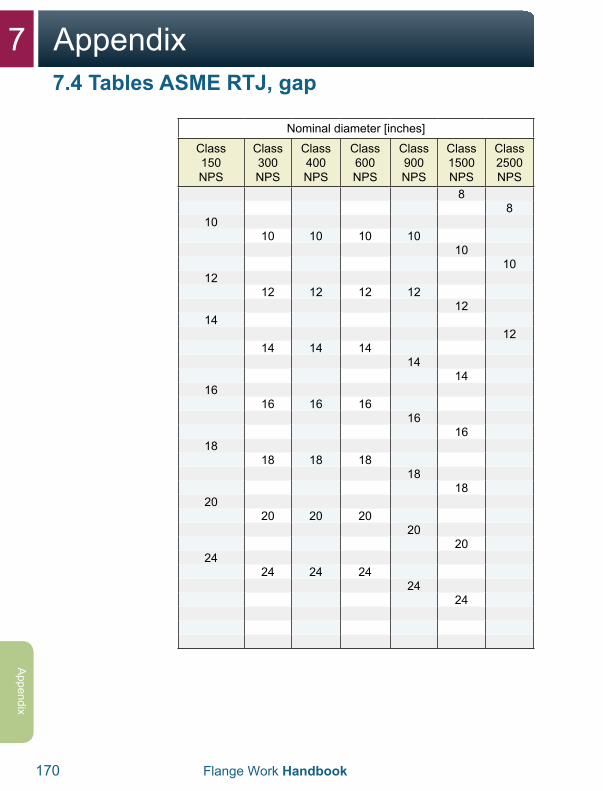
7 Appendix
170 Flange Work Handbook
Appendix
Nominal diameter [inches]
Class 150 NPS
Class 300 NPS
Class 400 NPS
Class 600 NPS
Class 900 NPS
Class 1500 NPS
Class 2500 NPS
88
1010 10 10 10
1010
1212 12 12 12
1214
1214 14 14
1414
1616 16 16
1616
1818 18 18
1818
2020 20 20
2020
2424 24 24
2424
7.4 Tables ASME RTJ, gap
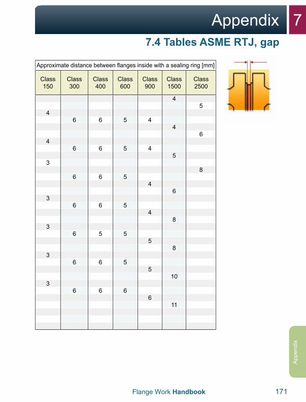
7Appendix
Flange Work Handbook 171
App
endi
x
Approximate distance between flanges inside with a sealing ring [mm]
Class 150
Class 300
Class 400
Class 600
Class 900
Class 1500
Class 2500
45
46 6 5 4
46
46 6 5 4
53
86 6 5
46
36 6 5
48
36 5 5
58
36 6 5
510
36 6 6
611
7.4 Tables ASME RTJ, gap
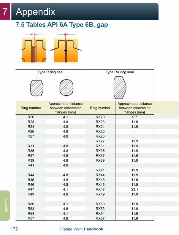
7 Appendix
172 Flange Work Handbook
Appendix
Type R ring seal Type RX ring seal
Ring numberApproximate distance between assembled
flanges [mm]Ring number
Approximate distance between assembled
flanges [mm]R20 4.1 RX20 9.7R23 4.8 RX23 11.9R24 4.8 RX24 11.9R26 4.8 RX25 -R27 4.8 RX26
RX27 11.9R31 4.8 RX31 11.9R35 4.8 RX35 11.9R37 4.8 RX37 11.9R39 4.8 RX39 11.9R41 4.8
RX41 11.9R44 4.8 RX44 11.9R45 4.8 RX45 11.9R46 4.8 RX46 11.9R47 4.1 RX47 23.1R49 4.8 RX49 11.9
R50 4.1 RX50 11.9R53 4.8 RX53 11.9R54 4.1 RX54 11.9R57 4.8 RX57 11.9
7.5 Tables API 6A Type 6B, gap
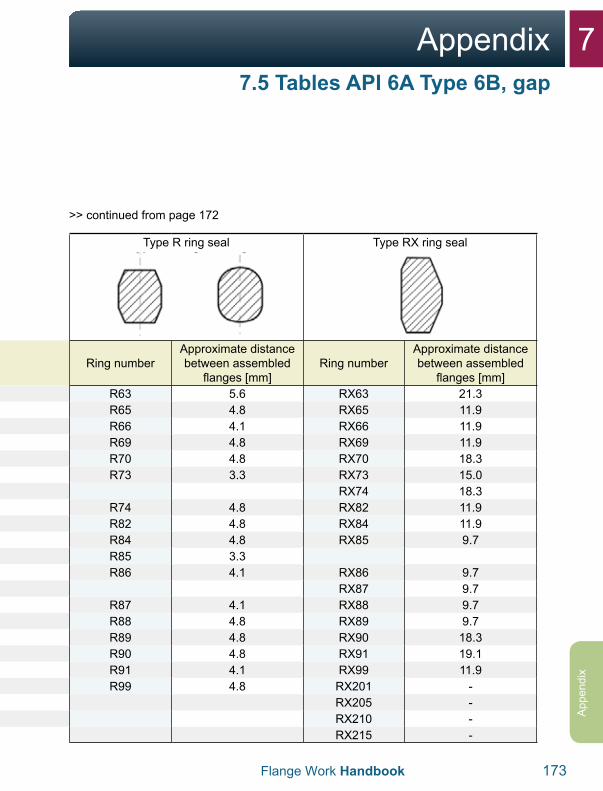
7Appendix
Flange Work Handbook 173
App
endi
x
Type R ring seal Type RX ring seal
Ring numberApproximate distance between assembled
flanges [mm]Ring number
Approximate distance between assembled
flanges [mm]R63 5.6 RX63 21.3R65 4.8 RX65 11.9R66 4.1 RX66 11.9R69 4.8 RX69 11.9R70 4.8 RX70 18.3R73 3.3 RX73 15.0
RX74 18.3R74 4.8 RX82 11.9R82 4.8 RX84 11.9R84 4.8 RX85 9.7R85 3.3R86 4.1 RX86 9.7
RX87 9.7R87 4.1 RX88 9.7R88 4.8 RX89 9.7R89 4.8 RX90 18.3R90 4.8 RX91 19.1R91 4.1 RX99 11.9R99 4.8 RX201 -
RX205 -RX210 -RX215 -
7.5 Tables API 6A Type 6B, gap
Type R ring seal Type RX ring seal
Ring numberApproximate distance between assembled
flanges [mm]Ring number
Approximate distance between assembled
flanges [mm]R20 4.1 RX20 9.7R23 4.8 RX23 11.9R24 4.8 RX24 11.9R26 4.8 RX25 -R27 4.8 RX26
RX27 11.9R31 4.8 RX31 11.9R35 4.8 RX35 11.9R37 4.8 RX37 11.9R39 4.8 RX39 11.9R41 4.8
RX41 11.9R44 4.8 RX44 11.9R45 4.8 RX45 11.9R46 4.8 RX46 11.9R47 4.1 RX47 23.1R49 4.8 RX49 11.9
R50 4.1 RX50 11.9R53 4.8 RX53 11.9R54 4.1 RX54 11.9R57 4.8 RX57 11.9
>> continued from page 172
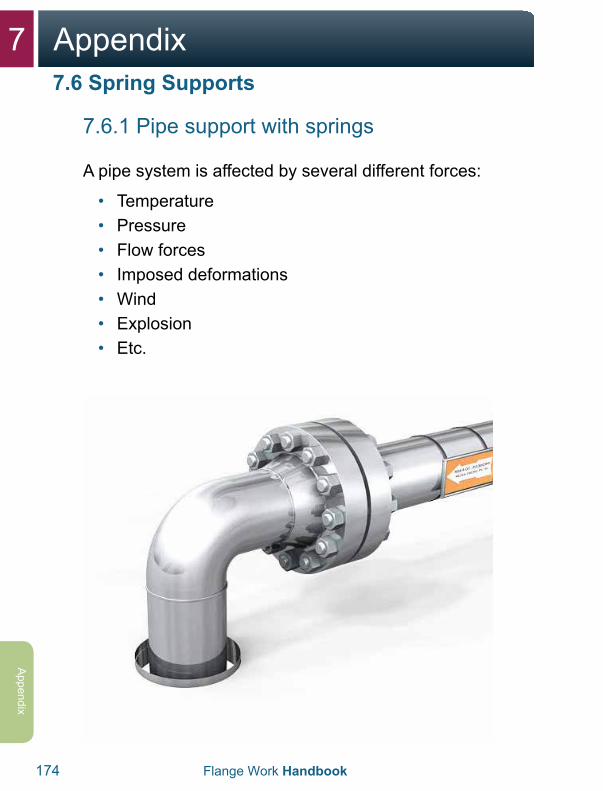
7 Appendix
174 Flange Work Handbook
Appendix
7.6.1 Pipe support with springs
A pipe system is affected by several different forces:
• Temperature• Pressure• Flow forces• Imposed deformations• Wind• Explosion• Etc.
7.6 Spring Supports
7Appendix
Flange Work Handbook 175
App
endi
x
To withstand these influences, a pipe system must be constructed in a controlled way. The goal with the construction is that the system shall be fixed at individual points, but it is allowed to shift at other points. It is especially important to avoid trapped tension forces because of either temperature or deformations suffered.
In some cases it is difficult to achieve a construction that ensures that the pipe is not overloaded because of weight, at the same time that you avoid trapped tension forces because of temperature or deformation. In such cases springs are often used (“spring supports”).
7.6 Spring Supports
7 Appendix
176 Flange Work Handbook
Appendix
7.6.2 Objective with springs
Springs are often used in situations where spigots on the equipment are involved. A spigot on a tank, pump, compressor or the like has a limited capacity to absorb the forces from the pipe system. Therefore, a pipe support should normally be installed in the immediate vicinity of the spigot to unload this.
In an ideal world without movement of these spigots or thermal expansion of the pipe, a normal pipe support would be enough to let this be. In practice, the situation is often that the spigot, temporarily, moves in relation to the pipe system’s other pipe supports. This is caused because the equipment has a thermal expansion between its fixed point and the spigot.
7.6 Spring Supports
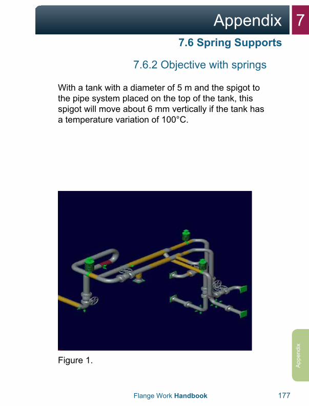
7Appendix
Flange Work Handbook 177
App
endi
x
7.6.2 Objective with springs
With a tank with a diameter of 5 m and the spigot to the pipe system placed on the top of the tank, this spigot will move about 6 mm vertically if the tank has a temperature variation of 100°C.
Figure 1.
7.6 Spring Supports
7 Appendix
178 Flange Work Handbook
Appendix
7.6.2 Objective with springs
If a normal “rest-support” (fixed pipe support) had been installed in the neighborhood of the spigot, the pipe will only lift from this pipe support when the tank became hot. (See figures 2 and 3.) If the tank was cooled, the pipe will be pressed down against the pipe support/beam and there could be large imposed forces.
If the pipe support is replaced with a flexible element (see figure 3) like a spring, the majority of the pipe’s weight will be borne by the spring. The spring will “follow” the tank’s movement when it is exposed to temperature changes.
7.6 Spring Supports
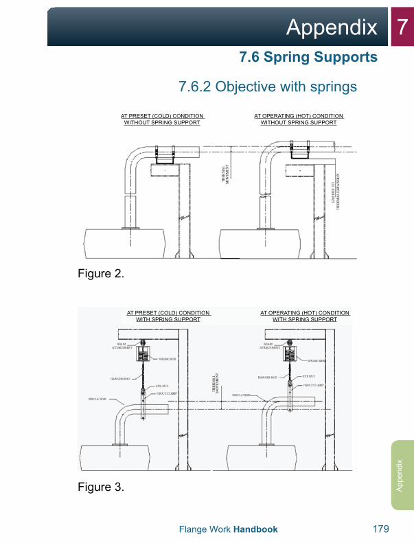
7Appendix
Flange Work Handbook 179
App
endi
x
7.6.2 Objective with springs
AT PRESET (COLD) CONDITION WITHOUT SPRING SUPPORT
AT OPERATING (HOT) CONDITION WITHOUT SPRING SUPPORT
Figure 2.
AT PRESET (COLD) CONDITION WITH SPRING SUPPORT
AT OPERATING (HOT) CONDITION WITH SPRING SUPPORT
Figure 3.
7.6 Spring Supports
7 Appendix
180 Flange Work Handbook
Appendix
7.6.3 Variable springs
The simplest spring type is a so-called variable spring. It is normally a device based on a coil spring. Such a spring is characterized by three parameters:
• Tension• Spring constant• Permitted movement
The spring is delivered in different models where the springs have different lengths, diameters and thickness to achieve the desired parameters. The spring constant is fixed for a concrete spring, but it is possible to change the tension to a certain degree by adjusting the spring.
Normally, a variable spring is constructed as shown in figure 4, 5 and 6.
7.6 Spring Supports
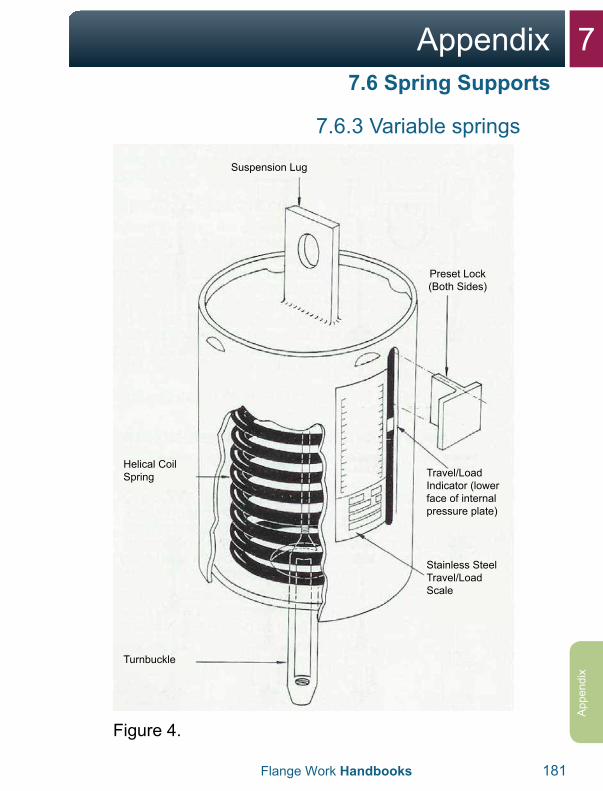
7Appendix
Flange Work Handbooks 181
App
endi
x
7.6.3 Variable springs
Suspension Lug
Preset Lock (Both Sides)
Travel/Load Indicator (lower face of internal pressure plate)
Stainless Steel Travel/Load Scale
Turnbuckle
Helical Coil Spring
Figure 4.
7.6 Spring Supports
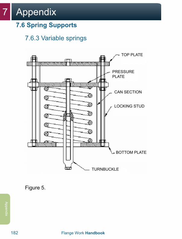
7 Appendix
182 Flange Work Handbook
Appendix
7.6.3 Variable springs
TOP PLATE
PRESSURE PLATE
CAN SECTION
LOCKING STUD
BOTTOM PLATE
TURNBUCKLE
Figure 5.
7.6 Spring Supports
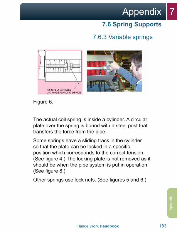
7Appendix
Flange Work Handbook 183
App
endi
x
7.6.3 Variable springs
INFINITELY VARIABLE LOCKING/BALANCING DEVICE
Figure 6.
The actual coil spring is inside a cylinder. A circular plate over the spring is bound with a steel post that transfers the force from the pipe.
Some springs have a sliding track in the cylinder so that the plate can be locked in a specific position which corresponds to the correct tension. (See figure 4.) The locking plate is not removed as it should be when the pipe system is put in operation. (See figure 8.)
Other springs use lock nuts. (See figures 5 and 6.)
7.6 Spring Supports
7 Appendix
184 Flange Work Handbook
Appendix
7.6.3 Variable springs
When the springs come from the supplier, the spring is pressed together corresponding to the correct tension, and there are metal pieces inserted that lock the plate in this position. This is done to simplify correct installation of the spring. (See figure 4.)
For spring types that use locking nuts, you can check if the spring has the correct load by trying to rotate the locking nuts on one or another side of the spring plate. If there is significant resistance, the spring is not correctly installed and adjusted. Adjustment is done by turning on the turnbuckle, for example (turnbuckle). (See figures 5, 10 and 11.)
The sliding track is labeled with a scale so that you can read the spring forces by looking where the plate over the spring lies in relation to the scale. From the scale you can also tell how much movement the spring allows in each direction. (See figures 7 and 9.)
7.6 Spring Supports
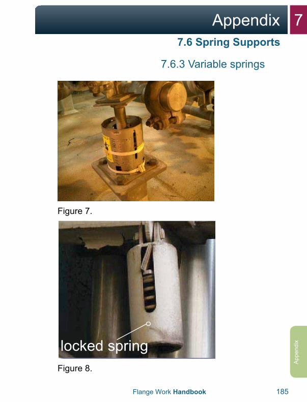
7Appendix
Flange Work Handbook 185
App
endi
x
7.6.3 Variable springs
Figure 7.
locked springFigure 8.
7.6 Spring Supports
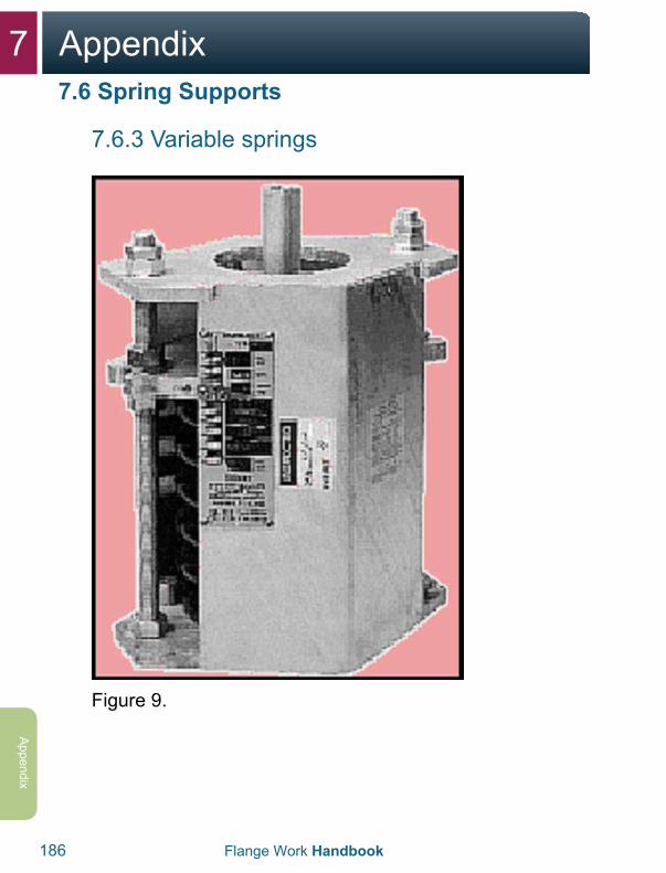
7 Appendix
186 Flange Work Handbook
Appendix
7.6.3 Variable springs
Figure 9.
7.6 Spring Supports
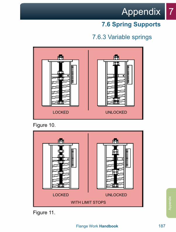
7Appendix
Flange Work Handbook 187
App
endi
x
7.6.3 Variable springs
LOCKED UNLOCKED
Figure 10.
LOCKED
WITH LIMIT STOPS
UNLOCKED
Figure 11.
7.6 Spring Supports
7 Appendix
188 Flange Work Handbook
Appendix
7.6.4 Constant springs
In some connections it is not acceptable that the construction forces vary with the pipe’s movement. His often applies to a connection with a spigot on sensitive equipment combined with large movements.
In such cases, constant springs are often used. These are devices that provide a nearly constant support force. In its simplest configuration, this can be as simple as a weight on a pulley that provides a constant force.
7.6 Spring Supports
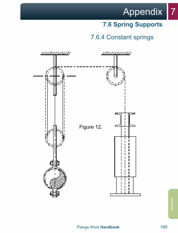
7Appendix
Flange Work Handbook 189
App
endi
x
7.6.4 Constant springs
7.6 Spring Supports
Figure 12.
7 Appendix
190 Flange Work Handbook
Appendix
7.6 Spring Supports
7.6.4 Constant springs
In offshore contexts, a coil spring that works on the pipe through a mechanism is the most common temporary solution, where the geometry is selected so that the change of the spring force is compensated by the mechanism.
A constant spring is characterized by two parameters:
• Load• Permitted movement
The desired load may be adjusted to some degree for a concrete spring.
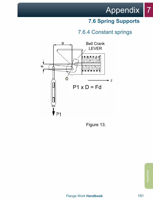
7Appendix
Flange Work Handbook 191
App
endi
x
7.6.4 Constant springs
Bell Crank LEVER
P1 x D = Fd
Figure 13.
7.6 Spring Supports
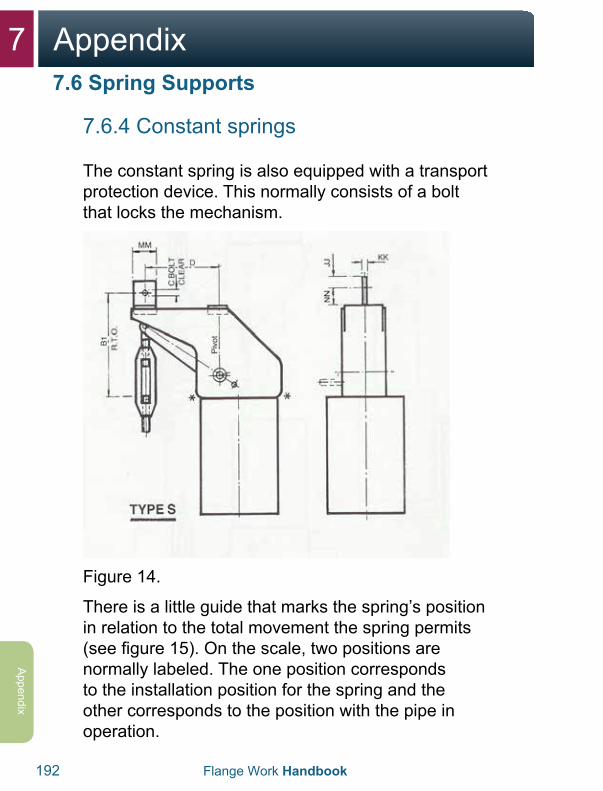
7 Appendix
192 Flange Work Handbook
Appendix
7.6 Spring Supports
7.6.4 Constant springs
The constant spring is also equipped with a transport protection device. This normally consists of a bolt that locks the mechanism.
Figure 14.
There is a little guide that marks the spring’s position in relation to the total movement the spring permits (see figure 15). On the scale, two positions are normally labeled. The one position corresponds to the installation position for the spring and the other corresponds to the position with the pipe in operation.
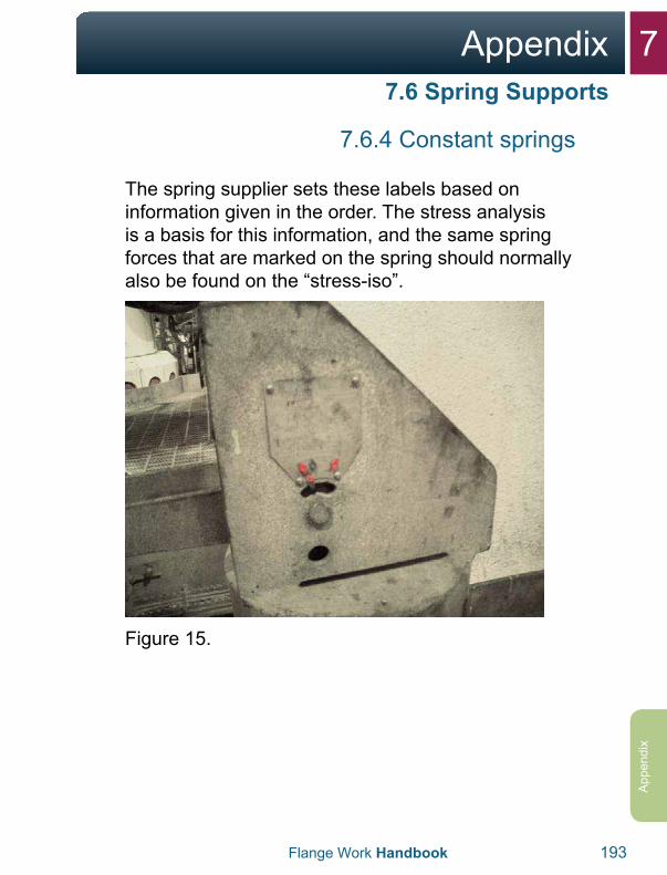
7Appendix
Flange Work Handbook 193
App
endi
x
7.6.4 Constant springs
The spring supplier sets these labels based on information given in the order. The stress analysis is a basis for this information, and the same spring forces that are marked on the spring should normally also be found on the “stress-iso”.
Figure 15.
7.6 Spring Supports
7 Appendix
194 Flange Work Handbook
Appendix
7.6.5 Installation in a cold system
The supplier normally has created an installation guideline that should be followed by the assigned personnel. If the installation guidelines are not attached to the work package, the assigned unit should ask to get them sent and should study them carefully before the work is done.
7.6 Spring Supports
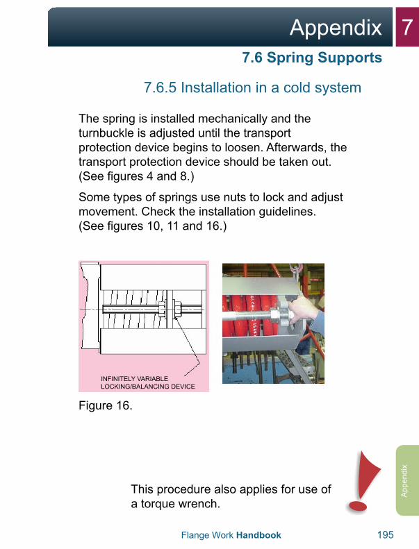
7Appendix
Flange Work Handbook 195
App
endi
x
7.6.5 Installation in a cold system
The spring is installed mechanically and the turnbuckle is adjusted until the transport protection device begins to loosen. Afterwards, the transport protection device should be taken out. (See figures 4 and 8.)
Some types of springs use nuts to lock and adjust movement. Check the installation guidelines. (See figures 10, 11 and 16.)
INFINITELY VARIABLE LOCKING/BALANCING DEVICE
Figure 16.
This procedure also applies for use of a torque wrench.
7.6 Spring Supports
7 Appendix
196 Flange Work Handbook
Appendix
7.6.6 Installation in a hot system
When the spring comes from the supplier, it is adjusted for installation in a cold system. This means that if the spring is installed in the same way as described above, for an installation in a cold system, the spring’s position will not be correct. The fact that the pipe will not be in the installation position needs to be compensated for.
To do this, those who are responsible for the installation need to find out at what height the pipe is. This should normally follow from a stress-iso. Here you should note that the values given on “stress-iso” normally refer to design temperatures, and it is not a given that the concrete pipe has exactly that temperature at the time of installation.
A typical example of this problem is springs on flow-lines. A flow-line connects the Christmas tree with production and test manifolds. Because of a combination of pressure, temperature and settings in the hill, the Christmas tree will move up and down. When the flow-line is in operation with maximum temperature and pressure, the spigot to the flow-line will be in its highest position, corresponding to the deformation that is used in the tension calculations. When a spring should be installed on a flow-line in operation, the flow-line will normally stay in a position somewhat under the maximum height dependent on how high the temperature and pressure of the media
7.6 Spring Supports
7Appendix
Flange Work Handbook 197
App
endi
x
7.6.6 Installation in a hot system
is. In such a situation, you should evaluate in which position the spring should be adjusted. You cannot set it in an “installation-position” until later since this corresponds to the position for a cold well.
If the spring is installed as though the well were cold, the spring can exceed the allowed movement when the well comes down again. This will cause abnormally large forces on the supports and can cause damage.
The spring is installed mechanically and the turnbuckle is adjusted until the transport protection device begins to loosen. Thereafter, the transport protection device is taken out. When the transport protection is out, the turnbuckle can be adjusted further so that it compensates for the fact that the pipe is not in a cold position. This means that if the pipe is 10 mm higher than it would be in a cold position, the spring should be expanded 10 mm.
To install a spring in a system that is hot is a demanding job that requires technical knowledge and insight. Normally, the supervising “Pipe Stress Engineer” should be contacted and give advice and guidance to those who do the installation job.
7.6 Spring Supports
7 Appendix
198 Flange Work Handbook
Appendix
7.6.7 Inspection
In connection with inspecting the existing springs, the following points should be checked:
1. Locking bricks/nuts (variable springs) or lockingpins (constant springs) should be removed.
2. The spring’s position in relation to the systemmovement should be correct. Check this. If ascale is not visible, normally the spring should bereplaced.
Different conditions over time can cause the situation to change so that the spring comes out of its original position. This can cause the spring to come outside of its work area, and this will then go to an end-position. If this occurs, the spring works as a fixed support and the face can be damaged.
7.6 Spring Supports
7Appendix
Flange Work Handbook 199
App
endi
x
7.6.7 Inspection
3. General conditions: Over time, the spring maybe damaged because of corrosion. Finally, thespring characteristics are changed because ofreduced material, or that parts of the spring havebroken off.
4. Check that “Spring Support” takes a load.
5. Condition of post and clamps around the pipe.
6. Check that movable parts are not corroded somuch that they don’t function.
7. A “Spring Support” should not be replaced witha chain, post or other similar without this beingapproved in advance by a supervising “PipeStress Engineer”.
7.6 Spring Supports
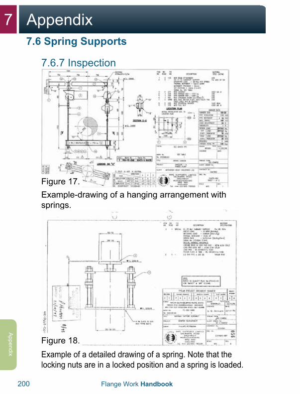
7 Appendix
200 Flange Work Handbook
Appendix
7.6.7 Inspection
Figure 17.Example-drawing of a hanging arrangement with springs.
Figure 18.Example of a detailed drawing of a spring. Note that the locking nuts are in a locked position and a spring is loaded.
7.6 Spring Supports

7Appendix
Flange Work Handbook 201
App
endi
x
(Installation) TAG NO.: ____________
1: Flange size _______ Pressure rating _________Spec.:__________
A: Flange material: Flange 1 __________ Flange 2 _________
B: Bolt size ________ Bolt quality ____________
C: Distance flange flange at 12:00 pm _____ at 3:00 pm _____ at 6:00 pm _____ at 9:00 pm _____
D: Distance flange flange at the seal surface: at 12:00 pm _____ at 3:00 pm _____ at 6:00 pm ______ at 9:00 pm _____
E: Tool type used ________ Tool number________ Pump pressure _________
Number of tools _______ Lubricant used ________
F: Gasket type used _________ Material ________ Size ___________
G: Tension in the pipe system _________ Is the pipe ready for tightening ______
H: Is the flange signed?___________ Is the right chart used? _____________
I: Which pump pressure were the nuts loosened with?________ PSI which tool no. ___________________ What does this correspond to in N·m? ___________ How much should this be tightened according to the chart? ________
2: Is the ring in accordance with the pipe spec or the bolting chart? ___________
A: Is the ring deformed? _________ Is it deformed evenly? _________ Is it deformed at points? _________
B: Is there movement in the ring when it is put into the track? ___________
C: With use of a new ring is there movement in that?____________
D: Is the blind flange used? _________ Is this free of damage?___________
E: Have the rings been used several times?_____________
F: Have the flanges been used several times? _____________
G: Is the ring track within tolerances? ___________
H: Are there foreign elements in the seal surface? ________ If so what? _______
Date:__________________ Signature:____________________________
7.7 Checklist for Leaking Flanges
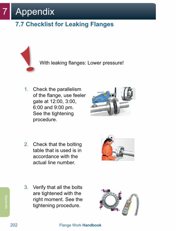
7 Appendix
202 Flange Work Handbook
Appendix
With leaking flanges: Lower pressure!
1. Check the parallelismof the flange, use feelergate at 12:00, 3:00,6:00 and 9:00 pm.See the tighteningprocedure.
2. Check that the boltingtable that is used is inaccordance with theactual line number.
3. Verify that all the boltsare tightened with theright moment. See thetightening procedure.
7.7 Checklist for Leaking Flanges

7Appendix
Flange Work Handbook 203
App
endi
x
4. If the flange has any leaks, disassemble andcheck:
Gasket type, material quality, gasket size andpressure rating.
Deformations and damage to flange/contactsurfaces.
Report to a qualifiedpersonnel for furtherevaluation.
5. Check that the contact surfaces and the bolt’sthreads are properlylubricated. Lubricateall the bolts.
6. Insert a new gasketand start the tighteningprocedure in accordancewith the applicable boltingchart.
7.7 Checklist for Leaking Flanges
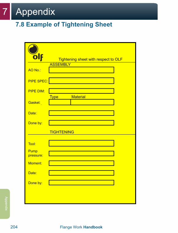
7 Appendix
204 Flange Work Handbook
Appendix
Tightening sheet with respect to OLFASSEMBLY
Type
TIGHTENING
Material
AO No.:
PIPE SPEC:
PIPE DIM:
Gasket:
Date:
Done by:
Done by:
Tool:
Moment:
Date:
Pump pressure:
7.8 Example of Tightening Sheet
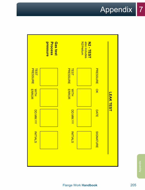
7Appendix
Flange Work Handbook 205
App
endi
x
LEAK
TEST
PR
ES
SU
RE
N2 - TEST
also includes N
2/Helium
Gas test
Process pressure
TES
T P
RE
SS
UR
E
TES
T P
RE
SS
UR
E
OK
WITH
E
RR
OR
WITH
E
RR
OR
DATE
DD
.MM
.YY
DD
.MM
.YY
SIG
NATU
RE
INITIA
LS
INITIA
LS
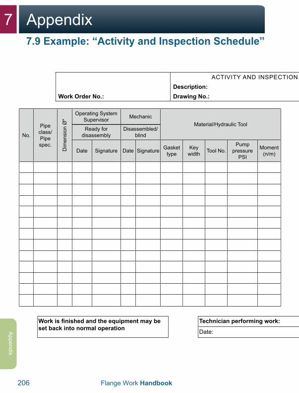
7 Appendix
206 Flange Work Handbook
Appendix
ACTIVITY AND INSPECTION SCHEDULE Isolation can start: Page ofDescription: Operating section:
Work Order No.: Drawing No.: Date: Signature:
No.
Pipe class/ Pipe spec.
Dim
ensi
on Ø
"
Operating System Supervisor Mechanic
Material/Hydraulic ToolMechanic Mechanic Operating System
SupervisorNotes Reviewed by another if: - tension in the pipe - multiple signatures
The back side can also be used if needed
Ready for disassembly
Disassembled/blind Assembled Finish tightened/
turned Approved
Date Signature Date Signature Gasket type
Key width Tool No.
Pump pressure
PSI
Moment (n/m) Date Signature Date Signature Date Signature
Work is finished and the equipment may be set back into normal operation
Technician performing work: Operating system supervisor approved:
Date: Signature: Date: Signature:
7.9 Example: “Activity and Inspection Schedule”
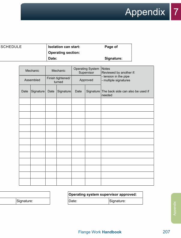
7Appendix
Flange Work Handbook 207
App
endi
x
ACTIVITY AND INSPECTION SCHEDULE Isolation can start: Page ofDescription: Operating section:
Work Order No.: Drawing No.: Date: Signature:
No.
Pipe class/Pipe spec.
Dim
ensi
on Ø
"
Operating System Supervisor Mechanic
Material/Hydraulic ToolMechanic Mechanic Operating System
SupervisorNotes Reviewed by another if: - tension in the pipe- multiple signatures
The back side can also be used if needed
Ready for disassembly
Disassembled/blind Assembled Finish tightened/
turned Approved
Date Signature Date Signature Gasket type
Key width Tool No.
Pump pressure
PSI
Moment (n/m) Date Signature Date Signature Date Signature
Work is finished and the equipment may be set back into normal operation
Technician performing work: Operating system supervisor approved:
Date: Signature: Date: Signature:
7 Appendix
208 Flange Work Handbook
Appendix

7Appendix
Flange Work Handbook 209
App
endi
x

210 Flange Work Handbook
Notes

Flange Work Handbook 211
Notes

212 Flange Work Handbook
Notes

Flange Work Handbook 213
Notes

214 Flange Work Handbook
Notes

Flange Work Handbook 215
Notes

If you have any questions, feedback or comments on the contents of the handbook, contact the head of Expertise
Development for the Norwegian Oil and Gas Association via the switchboard, telephone number +47
51 84 65 00.
www.norskoljeoggass.no