fittings - articoli tecnici e forniture industriali · working temperatures not exceeding 60 ¡c....
TRANSCRIPT
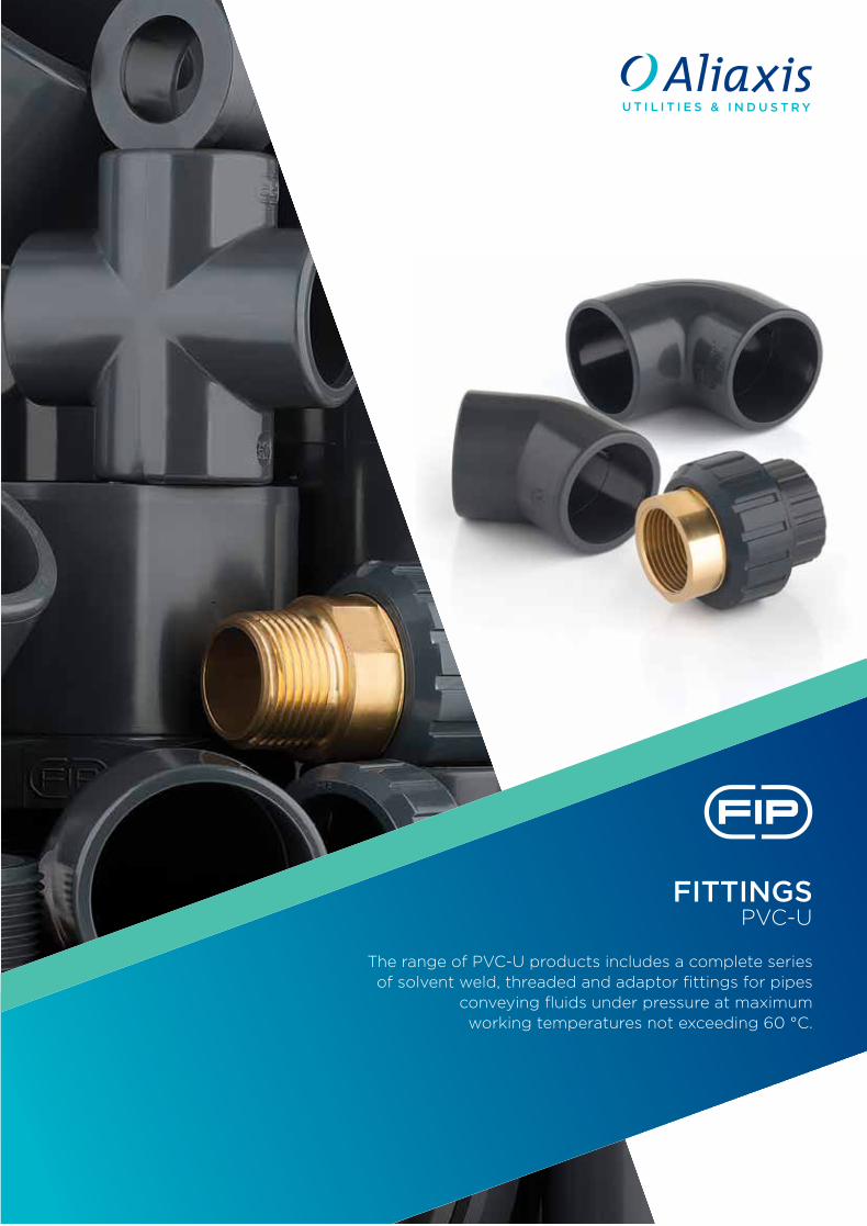
FITTINGSPVC-U
The range of PVC-U products includes a complete series of solvent weld, threaded and adaptor fittings for pipes
conveying fluids under pressure at maximum working temperatures not exceeding 60 °C.
PV
C-U
FITTINGS
LER
AC
CV
Cod
e
FIP Formatura Iniezione Polimeri Loc. Pian di Parata, 16015 Casella Genova ItalyTel. +39 010 9621.1 Fax +39 010 [email protected]
PVC-UGeneral characteristicsReference standardsApprovals and quality marksSolvent cementing instructions
page 2page 4page 6page 8
ISO-UNI fittingsSolvent weld fittings, metric series page 16
ISO-BSP fittingsAdaptor fittings page 50
BSP fittingsThreaded fittings page 72
BS fittingsSolvent weld and threaded fittings page 90
Key page 109
FITTINGS IN PVC-U
CONTENTS
PVC-U
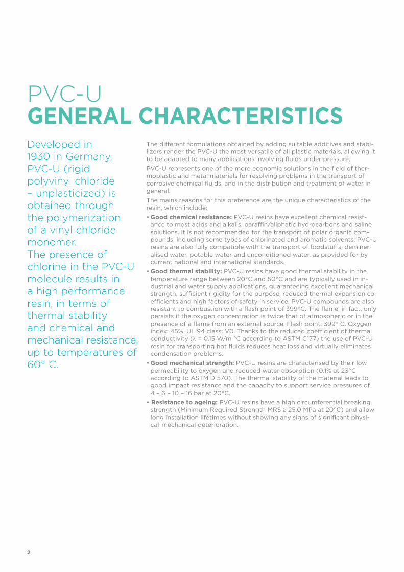
Developed in 1930 in Germany, PVC-U (rigid polyvinyl chloride – unplasticized) is obtained through the polymerization of a vinyl chloride monomer. The presence of chlorine in the PVC-U molecule results in a high performance resin, in terms of thermal stability and chemical and mechanical resistance, up to temperatures of 60° C.
The different formulations obtained by adding suitable additives and stabi-lizers render the PVC-U the most versatile of all plastic materials, allowing it to be adapted to many applications involving fluids under pressure.PVC-U represents one of the more economic solutions in the field of ther-moplastic and metal materials for resolving problems in the transport of corrosive chemical fluids, and in the distribution and treatment of water in general. The mains reasons for this preference are the unique characteristics of the resin, which include:• Good chemical resistance: PVC-U resins have excellent chemical resist-
ance to most acids and alkalis, paraffin/aliphatic hydrocarbons and saline solutions. It is not recommended for the transport of polar organic com-pounds, including some types of chlorinated and aromatic solvents. PVC-U resins are also fully compatible with the transport of foodstuffs, deminer-alised water, potable water and unconditioned water, as provided for by current national and international standards.
• Good thermal stability: PVC-U resins have good thermal stability in the temperature range between 20°C and 50°C and are typically used in in-dustrial and water supply applications, guaranteeing excellent mechanical strength, sufficient rigidity for the purpose, reduced thermal expansion co-efficients and high factors of safety in service. PVC-U compounds are also resistant to combustion with a flash point of 399°C. The flame, in fact, only persists if the oxygen concentration is twice that of atmospheric or in the presence of a flame from an external source. Flash point: 399° C. Oxygen index: 45%. UL 94 class: V0. Thanks to the reduced coefficient of thermal conductivity (O = 0.15 W/m °C according to ASTM C177) the use of PVC-U resin for transporting hot fluids reduces heat loss and virtually eliminates condensation problems.
• Good mechanical strength: PVC-U resins are characterised by their low permeability to oxygen and reduced water absorption (0.1% at 23°C according to ASTM D 570). The thermal stability of the material leads to good impact resistance and the capacity to support service pressures of 4 – 6 – 10 – 16 bar at 20°C.
• Resistance to ageing: PVC-U resins have a high circumferential breaking strength (Minimum Required Strength MRS t 25.0 MPa at 20°C) and allow long installation lifetimes without showing any signs of significant physi-cal-mechanical deterioration.
GENERAL CHARACTERISTICS
2
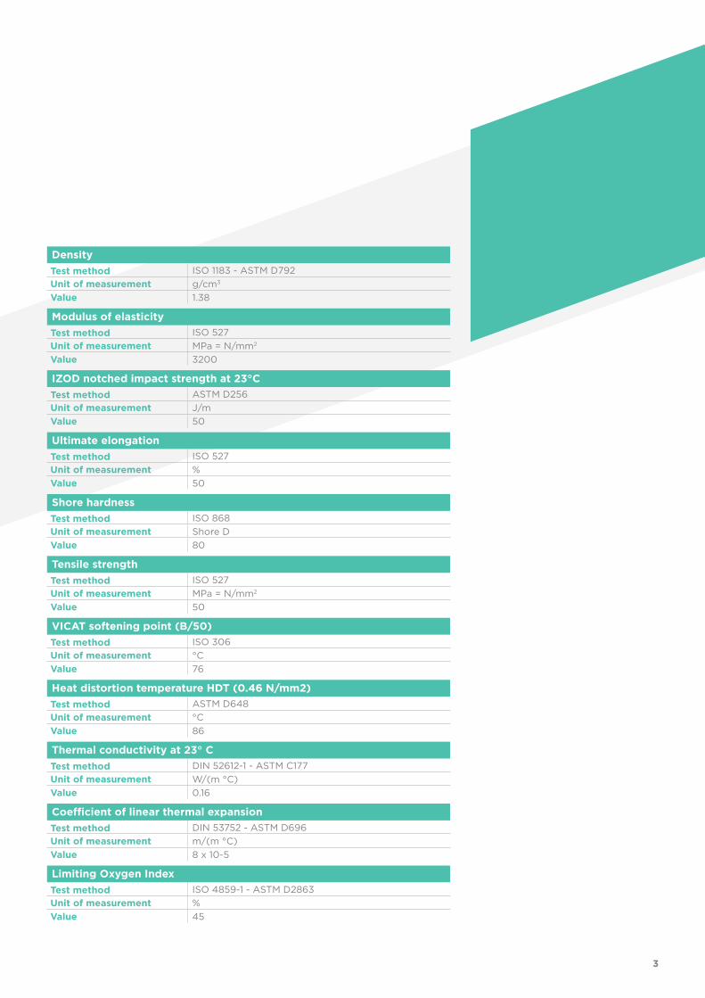
DensityTest method ISO 1183 - ASTM D792Unit of measurement g/cm3
Value 1.38
Modulus of elasticityTest method ISO 527Unit of measurement MPa = N/mm2
Value 3200
IZOD notched impact strength at 23°CTest method ASTM D256Unit of measurement J/mValue 50
Ultimate elongationTest method ISO 527Unit of measurement %Value 50
Shore hardnessTest method ISO 868Unit of measurement Shore DValue 80
Tensile strengthTest method ISO 527Unit of measurement MPa = N/mm2
Value 50
VICAT softening point (B/50)Test method ISO 306Unit of measurement °CValue 76
Heat distortion temperature HDT (0.46 N/mm2)Test method ASTM D648Unit of measurement °CValue 86
Thermal conductivity at 23° CTest method DIN 52612-1 - ASTM C177Unit of measurement W/(m °C)Value 0.16
Coefficient of linear thermal expansionTest method DIN 53752 - ASTM D696Unit of measurement m/(m °C)Value 8 x 10⁻⁵
Limiting Oxygen IndexTest method ISO 4859-1 - ASTM D2863Unit of measurement %Value 45
3
REFERENCE
• ASTM D 1785 Standard specification for pipes in PVC, Sch. 40-80-120• ASTM D 2464 Standard specification for threaded polyvinyl chloride (PVC) plastic pipe
fittings• ASTM D 2467 Standard specification for polyvinyl chloride (PVC) plastic pipe fittings,
sch. 80• BS 10 Specification for flanges and bolting for pipes, valves and fittings• BS 21 Specification for pipe threads for tubes and fittings• BS 3505 Specification for PVC-U pressure pipes for cold water supplies• BS 3506 Specification for PVC-U pipes for industrial use• BS 4346-1 Joints and fittings for use with solvent weld PVC pressure pipes• DIN 2501 Flange dimensions and drilling• DIN 2999 Whitworth pipe threads for threaded pipes and fittings• DIN 8062 PVC-U pipes - dimensions• DIN 8063 PVC-U pipe fittings - dimensions• DVS 2204 - DVS 2221 Adhesive bonding of thermoplastic PVC-U pipes and fittings• EN 1092-1 Flanges and their joints - Circular flanges for pipes, fittings, valves and
accessories - Part 1: PN designated steel flanges• EN ISO 1452 PVC-U pipes and fittings for water supply systems• EN ISO 15493 Plastic piping systems (Pipes, Fittings and Valves) in ABS, PVC-U, PVC-C
for industrial applications• ISO 7 PVC-U fittings with pressure-tight threaded joints• ISO 161-1 Dimensions of PVC-U pipes and fittings, metric series • ISO 228-1 PVC-U pipe fittings with threaded joints
STANDARDSThe PVC-U production line operates to the highest quality standards, in full compliance with current legislation governing environmental issues and in accordance with standard ISO 14001. All products are manufactured in accordance with a quality assurance system complying with standard ISO 9001.
4
• ISO 727 PVC-U pipes and fittings Dimensions and tolerances, metric series• JIS K 6741 PVC-U pipes• JIS B 0203 Tapered pipe threads• JIS K 6743 PVC-U pipe fittings for water supply systems• UNI 11242 Solvent welding of PVC-U pipes, fittings and valves
5
APPROVALS AND
• ABS The FIP PVC-U system is recognised as suitable for conveying and treating
sanitary and conditioning water onboard ships and other units classified by the American Bureau of Shipping (ABS)
• ACS France (Attestation de conformité Sanitaire) Suitability of PVC-U for food and beverage applications
• BSI (British Standards Institution UK) PVC-U fittings to BS 4346-1
• BUREAU VERITAS (France) Suitability of PVC-U for conveying and treating sanitary and conditioning
water in the maritime sector
• CSTB PVC-U fittings to standard NF T 54-028
• IIP N. 122 Istituto Italiano dei Plastici (Italian Plastics Institute) PVC-U fittings to standard UNI EN ISO 1452
QUALITY MARKS
6
• KIWA (Keurings Institut Voor Waterleiding Artikelen Holland)
PVC-U fittings to standard KIWA BRL K17301
• UKR-SEPRO FIP PVC-U fittings are certified in accordance with
Ukrainian Health, Safety, Hygiene and Quality stand-ards
• WRAS (Water regulations advisory scheme - UK) Suitability of PVC-U for transporting potable water
7
SOLVENT WELDINGINSTRUCTIONS
Fig. 2
Fig. 1
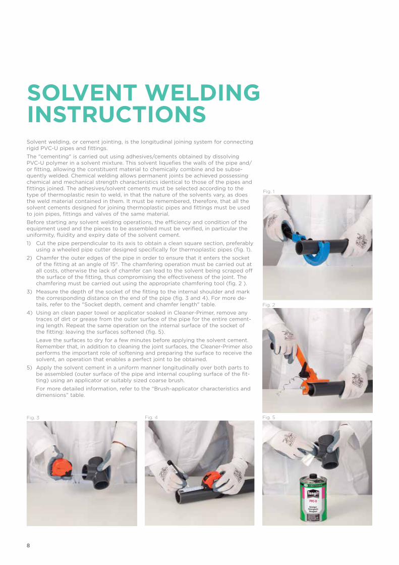
Solvent welding, or cement jointing, is the longitudinal joining system for connecting rigid PVC-U pipes and fittings.The "cementing" is carried out using adhesives/cements obtained by dissolving PVC-U polymer in a solvent mixture. This solvent liquefies the walls of the pipe and/or fitting, allowing the constituent material to chemically combine and be subse-quently welded. Chemical welding allows permanent joints be achieved possessing chemical and mechanical strength characteristics identical to those of the pipes and fittings joined. The adhesives/solvent cements must be selected according to the type of thermoplastic resin to weld, in that the nature of the solvents vary, as does the weld material contained in them. It must be remembered, therefore, that all the solvent cements designed for joining thermoplastic pipes and fittings must be used to join pipes, fittings and valves of the same material.Before starting any solvent welding operations, the efficiency and condition of the equipment used and the pieces to be assembled must be verified, in particular the uniformity, fluidity and expiry date of the solvent cement. 1) Cut the pipe perpendicular to its axis to obtain a clean square section, preferably
using a wheeled pipe cutter designed specifically for thermoplastic pipes (fig. 1).2) Chamfer the outer edges of the pipe in order to ensure that it enters the socket
of the fitting at an angle of 15°. The chamfering operation must be carried out at all costs, otherwise the lack of chamfer can lead to the solvent being scraped off the surface of the fitting, thus compromising the effectiveness of the joint. The chamfering must be carried out using the appropriate chamfering tool (fig. 2 ).
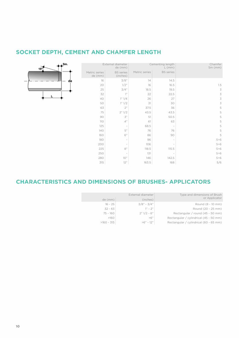
3) Measure the depth of the socket of the fitting to the internal shoulder and mark the corresponding distance on the end of the pipe (fig. 3 and 4). For more de-tails, refer to the "Socket depth, cement and chamfer length" table.
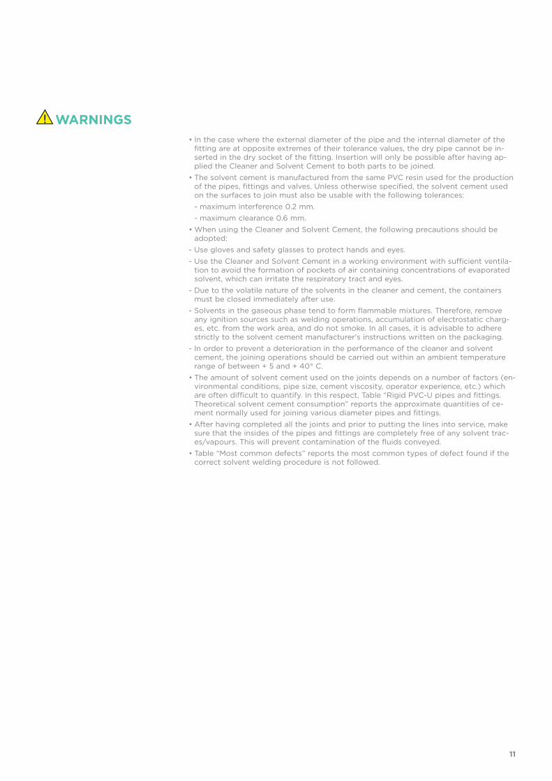
4) Using an clean paper towel or applicator soaked in Cleaner-Primer, remove any traces of dirt or grease from the outer surface of the pipe for the entire cement-ing length. Repeat the same operation on the internal surface of the socket of the fitting: leaving the surfaces softened (fig. 5).
Leave the surfaces to dry for a few minutes before applying the solvent cement. Remember that, in addition to cleaning the joint surfaces, the Cleaner-Primer also performs the important role of softening and preparing the surface to receive the solvent, an operation that enables a perfect joint to be obtained.
5) Apply the solvent cement in a uniform manner longitudinally over both parts to be assembled (outer surface of the pipe and internal coupling surface of the fit-ting) using an applicator or suitably sized coarse brush.
For more detailed information, refer to the “Brush-applicator characteristics and dimensions” table.
Fig. 3 Fig. 4 Fig. 5
8
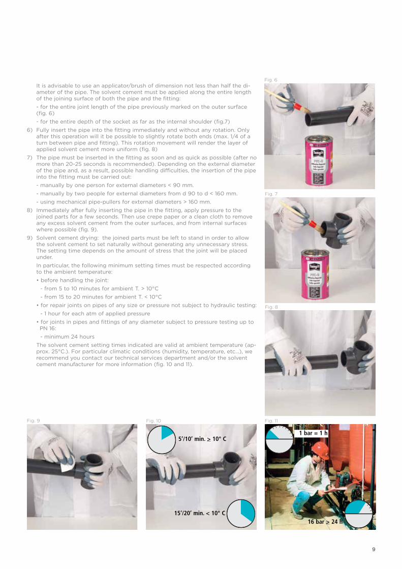
Fig. 6 It is advisable to use an applicator/brush of dimension not less than half the di-
ameter of the pipe. The solvent cement must be applied along the entire length of the joining surface of both the pipe and the fitting:
- for the entire joint length of the pipe previously marked on the outer surface (fig. 6)
- for the entire depth of the socket as far as the internal shoulder (fig.7)6) Fully insert the pipe into the fitting immediately and without any rotation. Only
after this operation will it be possible to slightly rotate both ends (max. 1/4 of a turn between pipe and fitting). This rotation movement will render the layer of applied solvent cement more uniform (fig. 8)
7) The pipe must be inserted in the fitting as soon and as quick as possible (after no more than 20-25 seconds is recommended). Depending on the external diameter of the pipe and, as a result, possible handling difficulties, the insertion of the pipe into the fitting must be carried out:
- manually by one person for external diameters < 90 mm. - manually by two people for external diameters from d 90 to d < 160 mm. - using mechanical pipe-pullers for external diameters > 160 mm.8) Immediately after fully inserting the pipe in the fitting, apply pressure to the
joined parts for a few seconds. Then use crepe paper or a clean cloth to remove any excess solvent cement from the outer surfaces, and from internal surfaces where possible (fig. 9).
9) Solvent cement drying: the joined parts must be left to stand in order to allow the solvent cement to set naturally without generating any unnecessary stress. The setting time depends on the amount of stress that the joint will be placed under.
In particular, the following minimum setting times must be respected according to the ambient temperature:
• before handling the joint: - from 5 to 10 minutes for ambient T. > 10°C - from 15 to 20 minutes for ambient T. < 10°C
• for repair joints on pipes of any size or pressure not subject to hydraulic testing: - 1 hour for each atm of applied pressure
• for joints in pipes and fittings of any diameter subject to pressure testing up to PN 16:
- minimum 24 hours The solvent cement setting times indicated are valid at ambient temperature (ap-
prox. 25°C.). For particular climatic conditions (humidity, temperature, etc…), we recommend you contact our technical services department and/or the solvent cement manufacturer for more information (fig. 10 and 11).
Fig. 7
Fig. 8
Fig. 9 Fig. 10
5’/10’ min. > 10° C
15’/20’ min. < 10° C
Fig. 11
16 bar > 24 h
1 bar = 1 h
9
SOCKET DEPTH, CEMENT AND CHAMFER LENGTH
External diameterde (mm)
Cementing lengthL (mm)
ChamferSm (mm)
Metric series de (mm)
BS series (inches)
Metric series BS series
16 3/8” 14 14.520 1/2” 16 16.5 1.525 3/4” 18.5 19.5 332 1” 22 22.5 340 1” 1/4 26 27 350 1” 1/2 31 30 363 2” 37.5 36 575 2” 1/2 43.5 43.5 590 3” 51 50.5 5110 4” 61 63 5125 - 68.5 - 5140 5” 76 76 5160 6” 86 90 5180 - 96 - 5÷6
200 - 106 - 5÷6225 8” 118.5 115.5 5÷6250 - 131 - 5÷6280 10” 146 142.5 5÷6315 12” 163.5 168 5/6
CHARACTERISTICS AND DIMENSIONS OF BRUSHES- APPLICATORS
External diameter Type and dimensions of Brush or Applicatorde (mm) (inches)
16 - 25 3/8” - 3/4” Round (8 - 10 mm)32 - 63 1” - 2” Round (20 - 25 mm)
75 - 160 2” 1/2 - 6” Rectangular / round (45 - 50 mm)>160 >6” Rectangular / cylindrical (45 - 50 mm)
>160 - 315 >6” - 12” Rectangular / cylindrical (60 - 65 mm)
10
• In the case where the external diameter of the pipe and the internal diameter of the fitting are at opposite extremes of their tolerance values, the dry pipe cannot be in-serted in the dry socket of the fitting. Insertion will only be possible after having ap-plied the Cleaner and Solvent Cement to both parts to be joined.
• The solvent cement is manufactured from the same PVC resin used for the production of the pipes, fittings and valves. Unless otherwise specified, the solvent cement used on the surfaces to join must also be usable with the following tolerances:
- maximum interference 0.2 mm. - maximum clearance 0.6 mm. • When using the Cleaner and Solvent Cement, the following precautions should be
adopted:- Use gloves and safety glasses to protect hands and eyes.- Use the Cleaner and Solvent Cement in a working environment with sufficient ventila-
tion to avoid the formation of pockets of air containing concentrations of evaporated solvent, which can irritate the respiratory tract and eyes.
- Due to the volatile nature of the solvents in the cleaner and cement, the containers must be closed immediately after use.
- Solvents in the gaseous phase tend to form flammable mixtures. Therefore, remove any ignition sources such as welding operations, accumulation of electrostatic charg-es, etc. from the work area, and do not smoke. In all cases, it is advisable to adhere strictly to the solvent cement manufacturer's instructions written on the packaging.
- In order to prevent a deterioration in the performance of the cleaner and solvent cement, the joining operations should be carried out within an ambient temperature range of between + 5 and + 40° C.
• The amount of solvent cement used on the joints depends on a number of factors (en-vironmental conditions, pipe size, cement viscosity, operator experience, etc.) which are often difficult to quantify. In this respect, Table “Rigid PVC-U pipes and fittings. Theoretical solvent cement consumption” reports the approximate quantities of ce-ment normally used for joining various diameter pipes and fittings.
• After having completed all the joints and prior to putting the lines into service, make sure that the insides of the pipes and fittings are completely free of any solvent trac-es/vapours. This will prevent contamination of the fluids conveyed.
• Table “Most common defects” reports the most common types of defect found if the correct solvent welding procedure is not followed.
WARNINGS
11
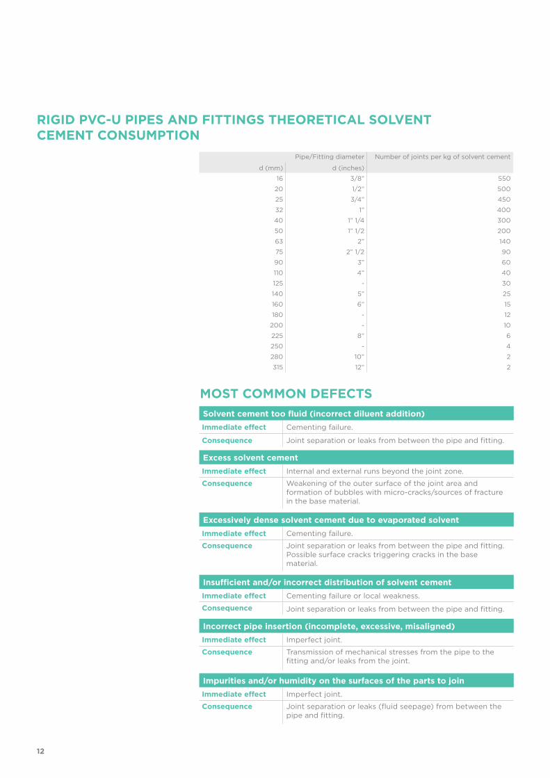
RIGID PVC-U PIPES AND FITTINGS THEORETICAL SOLVENT CEMENT CONSUMPTION
MOST COMMON DEFECTS
Pipe/Fitting diameter Number of joints per kg of solvent cement
d (mm) d (inches)16 3/8” 550
20 1/2” 50025 3/4” 45032 1” 40040 1” 1/4 30050 1” 1/2 20063 2” 14075 2” 1/2 9090 3” 60110 4” 40125 - 30140 5” 25160 6” 15180 - 12
200 - 10225 8” 6250 - 4280 10” 2315 12” 2
Solvent cement too fluid (incorrect diluent addition)Immediate effect Cementing failure.
Consequence Joint separation or leaks from between the pipe and fitting.
Excess solvent cementImmediate effect Internal and external runs beyond the joint zone.
Consequence Weakening of the outer surface of the joint area and formation of bubbles with micro-cracks/sources of fracture in the base material.
Excessively dense solvent cement due to evaporated solventImmediate effect Cementing failure.
Consequence Joint separation or leaks from between the pipe and fitting.Possible surface cracks triggering cracks in the base material.
Insufficient and/or incorrect distribution of solvent cementImmediate effect Cementing failure or local weakness.
Consequence Joint separation or leaks from between the pipe and fitting.
Incorrect pipe insertion (incomplete, excessive, misaligned)Immediate effect Imperfect joint.
Consequence Transmission of mechanical stresses from the pipe to the fitting and/or leaks from the joint.
Impurities and/or humidity on the surfaces of the parts to joinImmediate effect Imperfect joint.
Consequence Joint separation or leaks (fluid seepage) from between the pipe and fitting.
12

13

ISO-UNI FITTINGSPVC-U
Solvent weld fittings, metric series
16
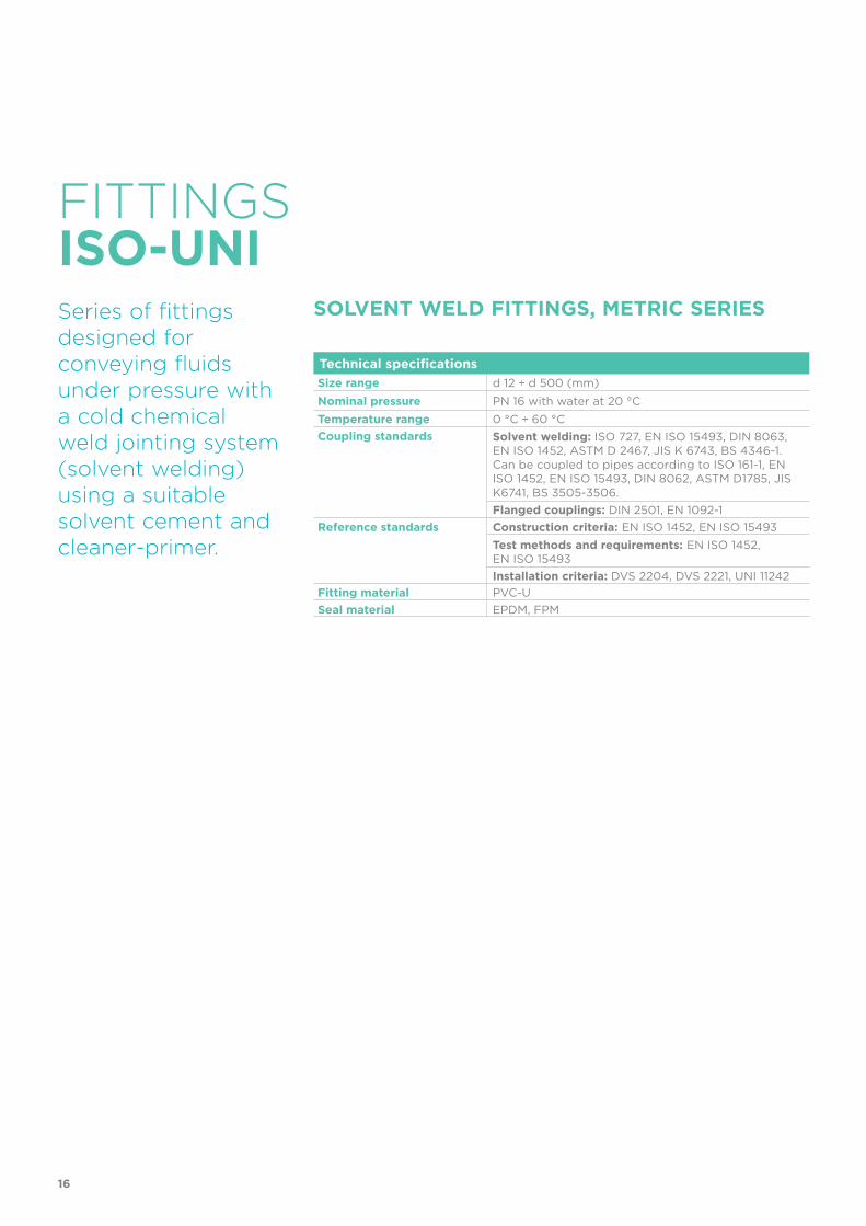
Technical specificationsSize range d 12 ÷ d 500 (mm)Nominal pressure PN 16 with water at 20 °CTemperature range 0 °C ÷ 60 °CCoupling standards Solvent welding: ISO 727, EN ISO 15493, DIN 8063,
EN ISO 1452, ASTM D 2467, JIS K 6743, BS 4346-1.Can be coupled to pipes according to ISO 161-1, EN ISO 1452, EN ISO 15493, DIN 8062, ASTM D1785, JIS K6741, BS 3505-3506. Flanged couplings: DIN 2501, EN 1092-1
Reference standards Construction criteria: EN ISO 1452, EN ISO 15493Test methods and requirements: EN ISO 1452, EN ISO 15493Installation criteria: DVS 2204, DVS 2221, UNI 11242
Fitting material PVC-USeal material EPDM, FPM
FITTINGS
Series of fittings designed forconveying fluidsunder pressure with a cold chemical weld jointing system (solvent welding) using a suitable solvent cement and cleaner-primer.
SOLVENT WELD FITTINGS, METRIC SERIES
ISO-UNI

17
REGRESSION CURVE FOR PVC-U FITTINGS
Ho
op
str
ess
Time to failure
bar0.1 1 10 102 103 104 105 106 h
20
25
304050
15
10
0.5
1
1.5
2
2.533.545
6789
20 °C30 °C40 °C
50 °C
60 °C
1 5 10 25 50 100Years
TECHNICAL DATA
-40 -20 0 20 40 60 80 100 120 140 °C
16
14
12
10
8
6
4
2
0
Wo
rkin
g p
ress
ure
Working temperature
barPRESSURE VARIATION ACCORDING TO TEMPERATURE
For water and non-hazardous fluids for which the material is classified as CHEMICALLY RESISTANT (life expectancy 25 years). In other cases, a reduction of the nominal pressure PN is required.
Regression coefficients according to EN ISO 1452 and EN ISO 15493 for MRS (minimum required strength) values = 25 N/mm2 (MPa) (classification PVC-U 250).
18
The information in this leaflet is provided in good faith. FIP will not be held liable for technical data not originating directly from recognised international standards. The company reserves the right to carry out any modifications. Products must be installed and maintained by qualified personnel.
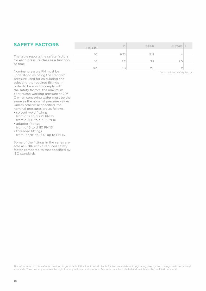
SAFETY FACTORS
The table reports the safety factors for each pressure class as a function of time.
Nominal pressure PN must be understood as being the standard pressure used for calculating and selecting the required fittings. In order to be able to comply with the safety factors, the maximum continuous working pressure at 20° C when conveying water must be the same as the nominal pressure values.Unless otherwise specified, the nominal pressures are as follows:• solvent weld fittings
from d 12 to d 225 PN 16 from d 250 to d 315 PN 10
• adaptor fittings from d 16 to d 110 PN 16
• threaded fittings from R 3/8” to R 4” up to PN 16.
Some of the fittings in the series are sold as PN16 with a reduced safety factor compared to that specified by ISO standards.
1h 1000h 50 years T
10 6.72 5.12 4
16 4.2 3.2 2.5
16* 3.3 2.5 2*with reduced safety factor
Pe (bar)

19
DIMENSIONS
d PN E L Z g Code
IH 20 16 27 16 40.5 35 SIV020IH 25 16 33 19 50 55 SIV025IH 32 16 41 22 65.5 100 SIV032IH 40 16 50 26 80.5 175 SIV040IH 50 16 61 31 100.5 280 SIV050IH 63 16 76 38 127 515 SIV063
I 75 16 94 44 150 1000 SIV075I 90 16 113 51 180 1770 SIV090I 110 16 137 61 220 2800 SIV110
I *160 16 189 86 207 5020 SIV160
SIV90° long radius bend (R=2d) with solvent weld sockets
I: IIP 122 H: KIWA K5034 ND 10*reduced safety factor (PN 10)
20
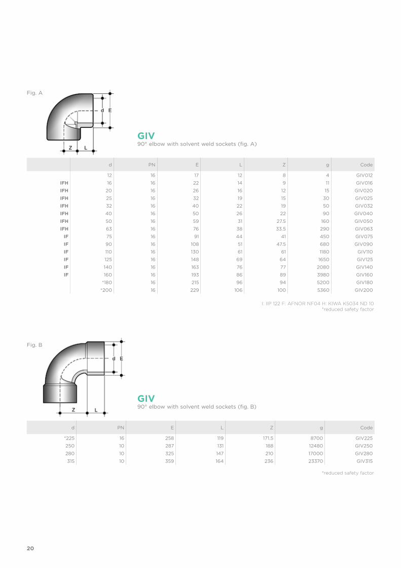
d PN E L Z g Code
12 16 17 12 8 4 GIV012IFH 16 16 22 14 9 11 GIV016IFH 20 16 26 16 12 15 GIV020IFH 25 16 32 19 15 30 GIV025IFH 32 16 40 22 19 50 GIV032IFH 40 16 50 26 22 90 GIV040IFH 50 16 59 31 27.5 160 GIV050IFH 63 16 76 38 33.5 290 GIV063
IF 75 16 91 44 41 450 GIV075IF 90 16 108 51 47.5 680 GIV090IF 110 16 130 61 61 1180 GIV110IF 125 16 148 69 64 1650 GIV125IF 140 16 163 76 77 2080 GIV140IF 160 16 193 86 89 3980 GIV160
*180 16 215 96 94 5200 GIV180*200 16 229 106 100 5360 GIV200
d PN E L Z g Code
*225 16 258 119 171.5 8700 GIV225250 10 287 131 188 12480 GIV250280 10 325 147 210 17000 GIV280315 10 359 164 236 23370 GIV315
GIV
GIV
90° elbow with solvent weld sockets (fig. A)
Fig. A
Fig. B
90° elbow with solvent weld sockets (fig. B)
I: IIP 122 F: AFNOR NF04 H: KIWA K5034 ND 10*reduced safety factor
*reduced safety factor

21
d PN E L Z g Code
12 16 17 12 4 5 HIV01216 16 21 14 5 6 HIV016
IFH 20 16 28 16 5.5 20 HIV020IFH 25 16 33 19 6 26 HIV025IFH 32 16 41 22 7.5 45 HIV032IFH 40 16 50 26 10.5 70 HIV040IFH 50 16 61 31 11.5 120 HIV050IFH 63 16 76 38 14 200 HIV063
IF 75 16 90 44 17 320 HIV075IF 90 16 107 51 21.5 550 HIV090IF 110 16 130 61 26 915 HIV110IF 125 16 147 69 31 1315 HIV125IF 140 16 163 76 34 1660 HIV140IF 160 16 192 86 38 3060 HIV160
**180 4 208 97 38 3500 HIV180200 10 230 108 48 4500 HIV200225 10 260 121 55 6400 HIV225250 10 286 131 58 7700 HIV250280 10 320 146 62 10460 HIV280315 10 359 164 66 15500 HIV315
HIV45° elbow with solvent weld sockets
I: IIP 122 F: AFNOR NF04 H: KIWA K5034 ND 10**resale product
22
d PN E L Z g Code
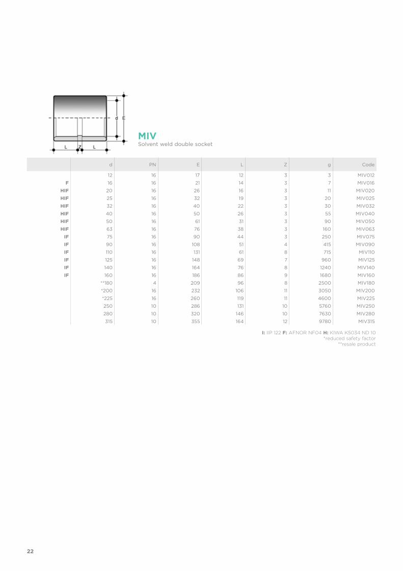
12 16 17 12 3 3 MIV012F 16 16 21 14 3 7 MIV016
HIF 20 16 26 16 3 11 MIV020HIF 25 16 32 19 3 20 MIV025HIF 32 16 40 22 3 30 MIV032HIF 40 16 50 26 3 55 MIV040HIF 50 16 61 31 3 90 MIV050HIF 63 16 76 38 3 160 MIV063
IF 75 16 90 44 3 250 MIV075IF 90 16 108 51 4 415 MIV090IF 110 16 131 61 8 715 MIV110IF 125 16 148 69 7 960 MIV125IF 140 16 164 76 8 1240 MIV140IF 160 16 186 86 9 1680 MIV160
**180 4 209 96 8 2500 MIV180*200 16 232 106 11 3050 MIV200*225 16 260 119 11 4600 MIV225250 10 286 131 10 5760 MIV250280 10 320 146 10 7630 MIV280315 10 355 164 12 9780 MIV315
MIVSolvent weld double socket
I: IIP 122 F: AFNOR NF04 H: KIWA K5034 ND 10*reduced safety factor
**resale product
23
d PN E L Z g Code
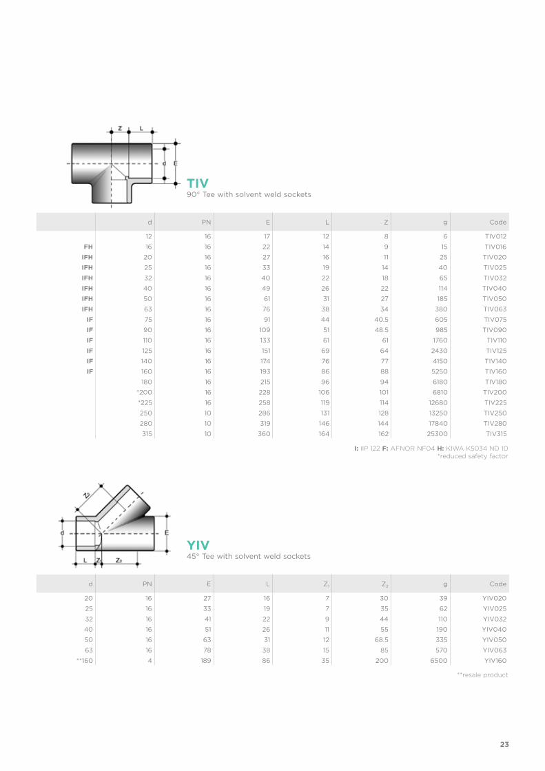
12 16 17 12 8 6 TIV012FH 16 16 22 14 9 15 TIV016
IFH 20 16 27 16 11 25 TIV020IFH 25 16 33 19 14 40 TIV025IFH 32 16 40 22 18 65 TIV032IFH 40 16 49 26 22 114 TIV040IFH 50 16 61 31 27 185 TIV050IFH 63 16 76 38 34 380 TIV063
IF 75 16 91 44 40.5 605 TIV075IF 90 16 109 51 48.5 985 TIV090IF 110 16 133 61 61 1760 TIV110IF 125 16 151 69 64 2430 TIV125IF 140 16 174 76 77 4150 TIV140IF 160 16 193 86 88 5250 TIV160
180 16 215 96 94 6180 TIV180*200 16 228 106 101 6810 TIV200*225 16 258 119 114 12680 TIV225250 10 286 131 128 13250 TIV250280 10 319 146 144 17840 TIV280315 10 360 164 162 25300 TIV315
TIV90° Tee with solvent weld sockets
I: IIP 122 F: AFNOR NF04 H: KIWA K5034 ND 10*reduced safety factor
d PN E L Z1 Z2 g Code
20 16 27 16 7 30 39 YIV02025 16 33 19 7 35 62 YIV02532 16 41 22 9 44 110 YIV03240 16 51 26 11 55 190 YIV04050 16 63 31 12 68.5 335 YIV05063 16 78 38 15 85 570 YIV063
**160 4 189 86 35 200 6500 YIV160
YIV45° Tee with solvent weld sockets
**resale product
24
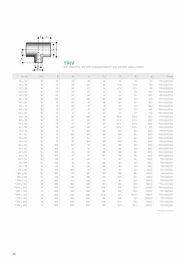
d x d1 PN E E1 L L1 Z Z1 g Code
25 x 20 16 33 28 19 16 14 14 37 TRIV02502032 x 20 16 41 28 22 16 17.5 17.5 60 TRIV03202032 x 25 16 41 34 22 19 17.5 17.5 65 TRIV03202540 x 20 16 50 29 26 16 22 22 100 TRIV04002040 x 25 16 50 34 26 19 22 22 100 TRIV04002540 x 32 16 50 42 26 22 22 22 105 TRIV04003250 x 20 16 61 30 31 16 27 27 160 TRIV05002050 x 25 16 61 35 31 19 27 27 160 TRIV05002550 x 32 16 61 42 31 22 27 27 165 TRIV05003250 x 40 16 61 51 31 26 27 27 170 TRIV05004063 x 25 16 76 36 38 19 33.5 33.5 290 TRIV06302563 x 32 16 76 43 38 22 33.5 33.5 295 TRIV06303263 x 40 16 76 52 38 26 33.5 33.5 300 TRIV06304063 x 50 16 76 62 38 31 33.5 33.5 315 TRIV06305075 x 32 16 91 41 44 22 40 40 530 TRIV07503275 x 40 16 91 50 44 26 40 40 540 TRIV07504075 x 50 16 91 61 44 31 40 40 550 TRIV07505075 x 63 16 91 76 44 38 40 40 580 TRIV075063
90 x 40 16 109 50 51 26 48 48 870 TRIV09004090 x 50 16 109 61 51 31 48 48 880 TRIV09005090 x 63 16 109 76 51 38 48 48 900 TRIV09006390 x 75 16 109 91 51 44 48 48 940 TRIV090075110 x 50 16 133 61 61 31 61 61 1580 TRIV110050110 x 63 16 133 76 61 38 61 61 1590 TRIV110063110 x 75 16 133 91 61 44 61 61 1610 TRIV110075110 x 90 16 133 109 61 51 61 61 1640 TRIV110090
**160 x 110 16 187 131 86 61 59 84 3450 TRIV160110180 x 125 16 215 151 96 69 94 94 6760 TRIV180125
**250 x 110 4 285 134 129 63 61 128 8300 TRIV250110**250 x 160 4 285 193 129 87 86 129 9900 TRIV250160
**250 x 200 4 285 228 129 106 133 132 12000 TRIV250200**280 x 160 4 320 193 146 88 84 153 12500 TRIV280160**280 x 225 4 320 258 146 117.5 117 150.5 14900 TRIV280225**315 x 160 4 355 193 164 86 83 161 15000 TRIV315160
**315 x 200 4 355 228 164 106 102 179 17500 TRIV315200**315 x 250 4 355 285 164 131 127 160 19200 TRIV315250
TRIV90° reducing Tee with reduced branch and solvent weld sockets
**resale product

25
d PN E L Z g Code
H 25 16 35 19 14 60 XIV025H 32 16 43 22 18 105 XIV032H 40 16 52 26 23 175 XIV040H 50 16 64 31 27 265 XIV050H 63 16 79 38 33.5 505 XIV063
XIV90° cross with solvent weld sockets
H: KIWA K5034 ND 10
d PN E H L g Code
12 16 17 15 12 3 CIV012F 16 16 21 17 15 4 CIV016
IF 20 16 28 23 16 9 CIV020IF 25 16 34 27 19 15 CIV025IF 32 16 41 31 22 25 CIV032IF 40 16 51 36 26 40 CIV040IF 50 16 62 43 31 60 CIV050IF 63 16 77 51 38 110 CIV063IF 75 16 91 59 44 190 CIV075IF 90 16 110 69 51 330 CIV090IF 110 16 133 85 61 575 CIV110IF 125 16 147 99 69 900 CIV125
140 16 164 108 76 1100 CIV140160 16 192 128 86 1900 CIV160225 10 260 163 119 3000 CIV225
CIVEnd cap with solvent weld socket
I: IIP 122 F: AFNOR NF04

26
d R1 PN E H L Z g Code
I 16 3/4” 16 33 41 14 13 20 BIV016EI 20 1” 16 41 45 16 13 35 BIV020EI 25 1” 1/4 16 50 51 19 13 60 BIV025EI 32 1” 1/2 16 58 57 22 13 85 BIV032EI 40 2” 16 72 67 26 15 150 BIV040EI 50 2” 1/4 16 79 79 31 17 175 BIV050EI 63 2” 3/4 16 98 98 38 22 320 BIV063E
75 3” 1/2 10 120 116 44 21 590 BIV075E90 4” 10 135 125 51 23 770 BIV090E110 5” 10 163 145 61 23 1300 BIV110E
BIVUnion with solvent weld socket, O-Ring in EPDM or FPM
R1 d BIV PN E F H g Code
3/8” - 16 23 13 20 5 EFV0381/2” - 16 27 17 24 8 EFV0123/4” 16 16 33 22 21 9 EFV034
1” 20 16 41 28 22 13 EFV1001” 1/4 25 16 50 36 25 22 EFV1141” 1/2 32 16 58 42 27 30 EFV112
2” 40 16 72 53 30 50 EFV2002” 1/4 50 16 79 59 34 68 EFV2142” 1/2 - 16 90 68 36 95 EFV2122” 3/4 63 16 98 74 38 120 EFV2343” 1/2 75 10 120 93 45 198 EFV312
4” 90 10 135 106 52 278 EFV4005” 110 10 163 129 60 448 EFV500
EFVUnion nut with BSP thread for union types BIV, BIFV, BFV, BLV, BIRV, BIFOV, BIROV, BIFXV, BIRXV
I: IIP 122

27
d R1 PN L Z g Code
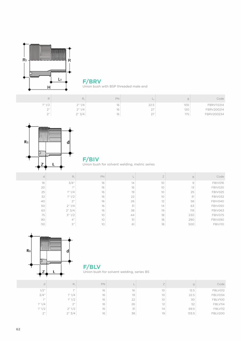
16 3/4” 16 14 10 9 FBIV01620 1” 16 16 10 13 FBIV02025 1” 1/4 16 19 10 25 FBIV02532 1” 1/2 16 22 10 31 FBIV03240 2” 16 26 12 58 FBIV04050 2” 1/4 16 31 14 63 FBIV05063 2” 3/4 16 38 19 119 FBIV06375 3” 1/2 10 44 18 230 FBIV07590 4” 10 51 18 290 FBIV090110 5” 10 61 18 500 FBIV110
F/BIVUnion bush for solvent welding, metric series
d R1 PN L Z g Code
1/2” 1” 16 16 10 12.5 FBLV0123/4” 1” 1/4 16 19 10 22.5 FBLV034
1” 1” 1/2 16 22 10 30 FBLV1001” 1/4 2” 16 26 12 52 FBLV1141” 1/2 2” 1/2 16 31 14 69.5 FBLV112
2” 2” 3/4 16 38 19 133.5 FBLV200
F/BLVUnion bush for solvent welding, series BS

28
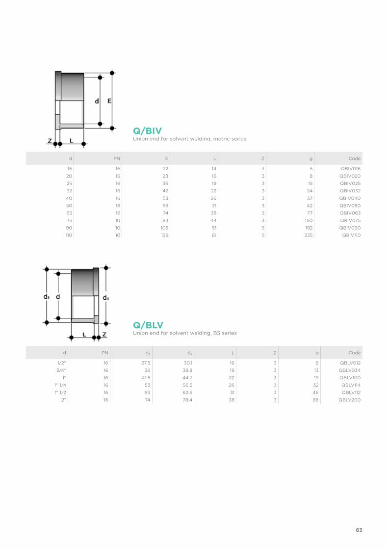
d PN d3 d4 L Z g Code
1/2” 16 27.5 30.1 16 3 8 QBLV0123/4” 16 36 38.8 19 3 13 QBLV034
1” 16 41.5 44.7 22 3 19 QBLV1001” 1/4 16 53 56.5 26 3 32 QBLV1141” 1/2 16 59 62.6 31 3 46 QBLV112
2” 16 74 78.4 38 3 86 QBLV200
Q/BLVUnion end for solvent welding, BS series
d PN E L Z g Code
16 16 22 14 3 5 QBIV01620 16 28 16 3 8 QBIV02025 16 36 19 3 15 QBIV02532 16 42 22 3 24 QBIV03240 16 53 26 3 37 QBIV04050 16 59 31 3 42 QBIV05063 16 74 38 3 77 QBIV06375 10 93 44 3 150 QBIV07590 10 105 51 5 192 QBIV090110 10 129 61 5 335 QBIV110
Q/BIVUnion end for solvent welding, metric series
29
d PN d3 d4 L Z g Code
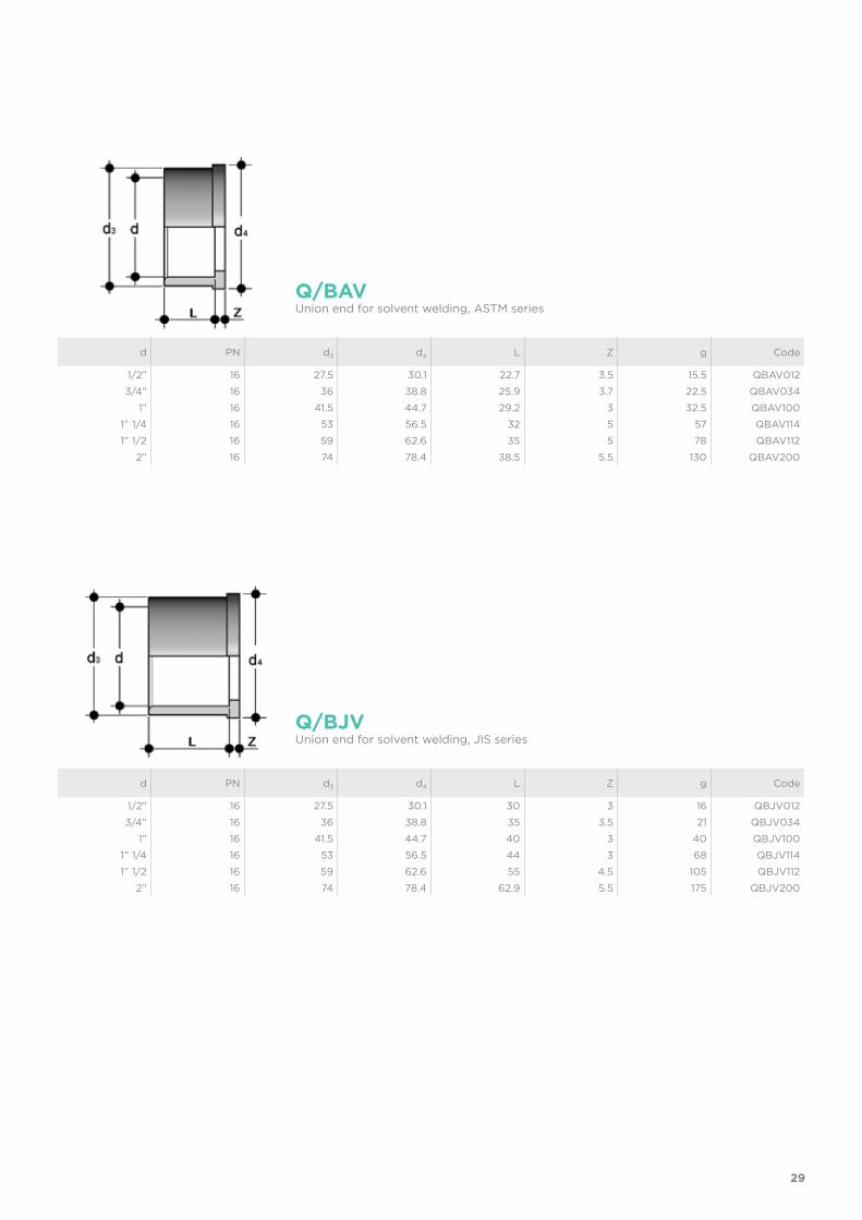
1/2” 16 27.5 30.1 22.7 3.5 15.5 QBAV012 3/4” 16 36 38.8 25.9 3.7 22.5 QBAV034
1” 16 41.5 44.7 29.2 3 32.5 QBAV100 1” 1/4 16 53 56.5 32 5 57 QBAV114 1” 1/2 16 59 62.6 35 5 78 QBAV112
2” 16 74 78.4 38.5 5.5 130 QBAV200
Q/BAVUnion end for solvent welding, ASTM series
d PN d3 d4 L Z g Code
1/2” 16 27.5 30.1 30 3 16 QBJV012 3/4” 16 36 38.8 35 3.5 21 QBJV034
1” 16 41.5 44.7 40 3 40 QBJV100 1” 1/4 16 53 56.5 44 3 68 QBJV114 1” 1/2 16 59 62.6 55 4.5 105 QBJV112
2” 16 74 78.4 62.9 5.5 175 QBJV200
Q/BJVUnion end for solvent welding, JIS series
30
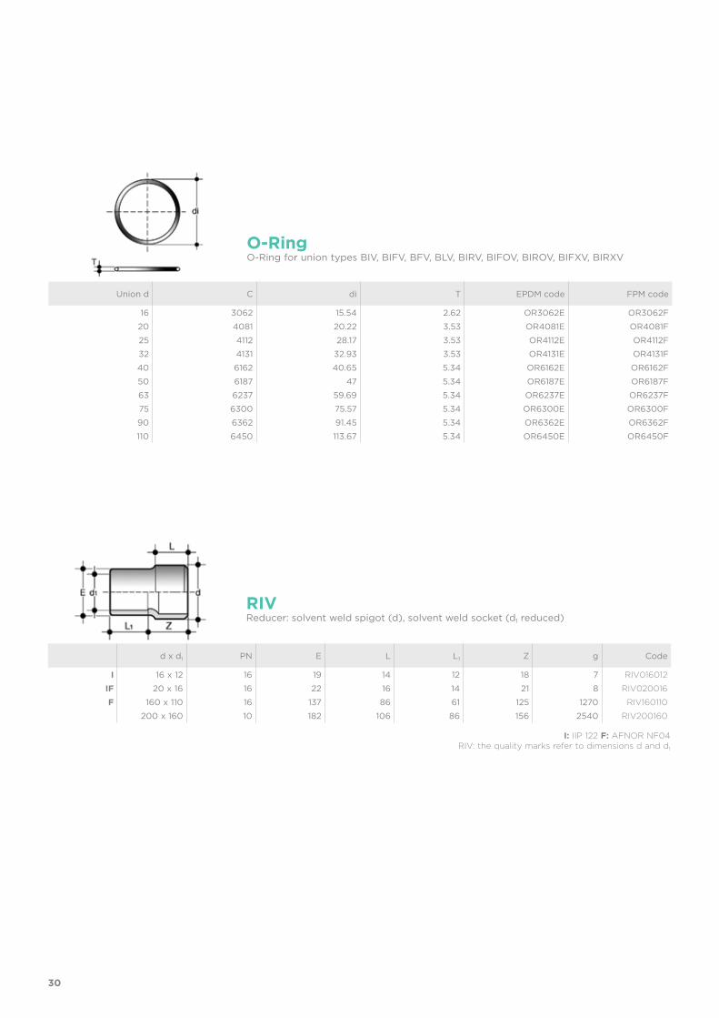
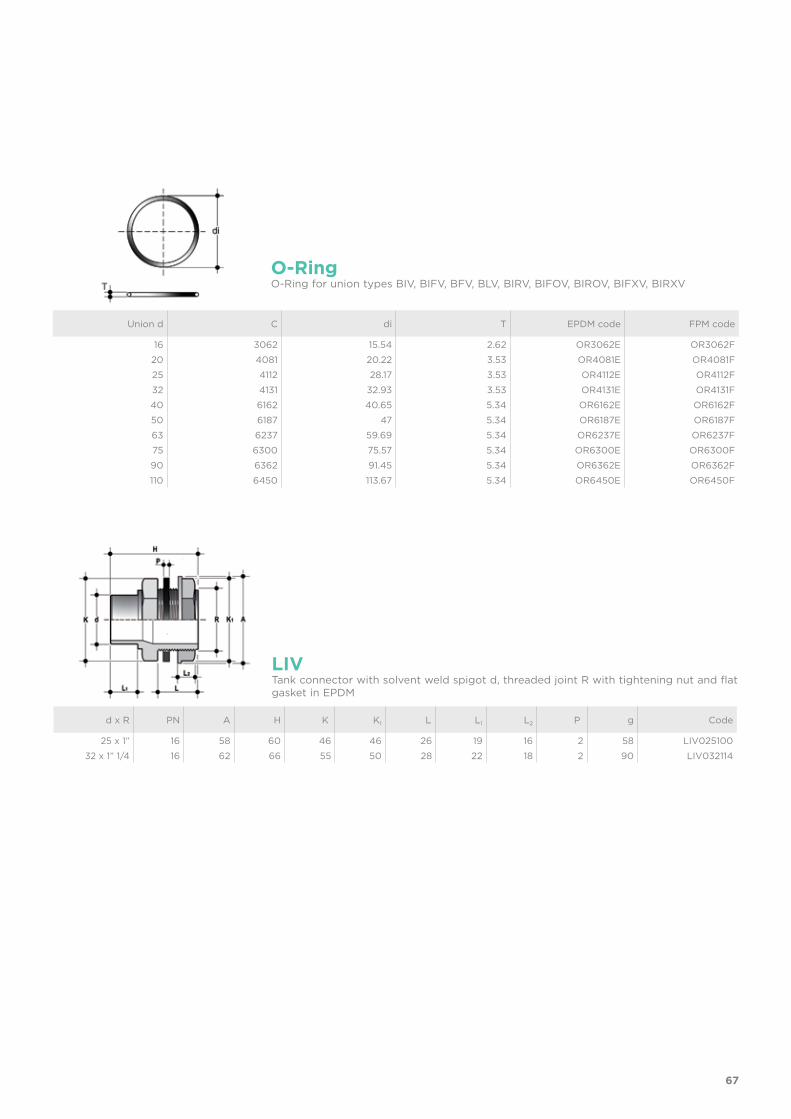
Union d C di T EPDM code FPM code
16 3062 15.54 2.62 OR3062E OR3062F20 4081 20.22 3.53 OR4081E OR4081F25 4112 28.17 3.53 OR4112E OR4112F32 4131 32.93 3.53 OR4131E OR4131F40 6162 40.65 5.34 OR6162E OR6162F50 6187 47 5.34 OR6187E OR6187F63 6237 59.69 5.34 OR6237E OR6237F75 6300 75.57 5.34 OR6300E OR6300F90 6362 91.45 5.34 OR6362E OR6362F110 6450 113.67 5.34 OR6450E OR6450F
O-RingO-Ring for union types BIV, BIFV, BFV, BLV, BIRV, BIFOV, BIROV, BIFXV, BIRXV
d x d1 PN E L L1 Z g Code
I 16 x 12 16 19 14 12 18 7 RIV016012
IF 20 x 16 16 22 16 14 21 8 RIV020016
F 160 x 110 16 137 86 61 125 1270 RIV160110
200 x 160 10 182 106 86 156 2540 RIV200160
RIVReducer: solvent weld spigot (d), solvent weld socket (d1 reduced)
I: IIP 122 F: AFNOR NF04RIV: the quality marks refer to dimensions d and d1
31
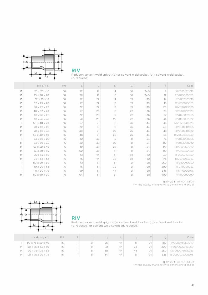
d x d2 x d3 x d1 PN E L L1 L2 L3 Z g Code
I 90 x 75 x 50 x 40 16 - 51 26 44 31 74 180 RIV090075050040
IF 90 x 75 x 63 x 50 16 - 51 31 44 38 74 200 RIV090075063050
IF 90 x 75 x 75 x 63 16 - 51 38 44 44 74 260 RIV090075075063
IF 90 x 75 x 90 x 75 16 - 51 44 44 51 74 325 RIV090075090075
RIVReducer: solvent weld spigot (d) or solvent weld socket (d2), solvent weld socket (d1 reduced) or solvent weld spigot (d3 reduced)
I: IIP 122 F: AFNOR NF04RIV: the quality marks refer to dimensions d and d1
d x d2 x d1 PN E L L1 L2 Z g Code
IF 25 x 20 x 16 16 22 19 14 16 24.5 9 RIV025020016
IF 25 x 20 x 20 16 26 19 16 16 24.5 12 RIV025020020
IF 32 x 25 x 16 16 22 22 14 19 30 14 RIV032025016
IF 32 x 25 x 20 16 27 22 16 19 30 16 RIV032025020
IF 32 x 25 x 25 16 32 22 19 19 30 20 RIV032025025
IF 40 x 32 x 20 16 27 26 16 22 36 23 RIV040032020
IF 40 x 32 x 25 16 32 26 19 22 36 27 RIV040032025
IF 40 x 32 x 32 16 41 26 22 22 36 34 RIV040032032
I 50 x 40 x 20 16 27 31 16 26 44 36 RIV050040020
IF 50 x 40 x 25 16 32 31 19 26 44 40 RIV050040025
IF 50 x 40 x 32 16 40 31 22 26 44 48 RIV050040032
IF 50 x 40 x 40 16 48 31 26 26 44 55 RIV050040040
I 63 x 50 x 25 16 32 38 19 31 54 75 RIV063050025
IF 63 x 50 x 32 16 40 38 22 31 54 80 RIV063050032
IF 63 x 50 x 40 16 49 38 26 31 54 90 RIV063050040
IF 63 x 50 x 50 16 60 38 31 31 54 110 RIV063050050
IF 75 x 63 x 50 16 61 44 31 38 62 130 RIV075063050
IF 75 x 63 x 63 16 76 44 38 38 62 175 RIV075063063
I 110 x 90 x 50 16 61 61 31 51 88 260 RIV110090050
I 110 x 90 x 63 16 76 61 38 51 88 300 RIV110090063
I 110 x 90 x 75 16 89 61 44 51 88 345 RIV110090075
IF 110 x 90 x 90 16 104 61 51 51 88 400 RIV110090090
RIVReducer: solvent weld spigot (d) or solvent weld socket (d2), solvent weld socket (d1 reduced)
I: IIP 122 F: AFNOR NF04RIV: the quality marks refer to dimensions d and d1
32
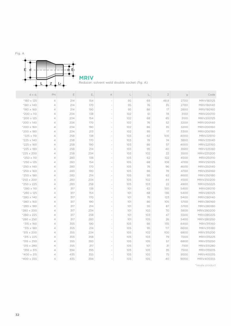
d x d1 PN E E1 K L L1 Z g Code
*180 x 125 4 214 154 - 95 68 48.8 2700 MRIV180125*180 x 140 4 214 170 - 95 76 35 2700 MRIV180140*180 x 160 4 214 190 - 95 86 17 2800 MRIV180160*200 x 110 4 234 138 - 102 61 78 3100 MRIV200110*200 x 125 4 234 154 - 102 68 65 3100 MRIV200125*200 x 140 4 234 170 - 102 76 52 3200 MRIV200140*200 x 160 4 234 190 - 102 86 35 3200 MRIV200160*200 x 180 4 234 213 - 102 95 17 3300 MRIV200180*225 x 110 4 258 138 - 103 62 100 4000 MRIV225110
*225 x 140 4 258 170 - 103 76 74 3800 MRIV225140*225 x 160 4 258 190 - 103 86 57 4000 MRIV225160*225 x 180 4 258 214 - 103 95 40 3500 MRIV225180
*225 x 200 4 258 234 - 103 102 22 3500 MRIV225200*250 x 110 4 283 138 - 105 62 122 4500 MRIV250110*250 x 125 4 283 154 - 105 68 108 4700 MRIV250125*250 x 140 4 283 170 - 105 76 96 4600 MRIV250140*250 x 160 4 283 190 - 105 86 78 4700 MRIV250160*250 x 180 4 283 214 - 105 95 62 4600 MRIV250180
*250 x 200 4 283 234 - 105 102 44 4500 MRIV250200*250 x 225 4 283 258 - 105 103 22 4900 MRIV250225*280 x 110 4 317 138 - 101 62 150 5400 MRIV280110*280 x 125 4 317 154 - 101 68 136 5400 MRIV280125*280 x 140 4 317 170 - 101 76 123 5400 MRIV280140*280 x 160 4 317 190 - 101 86 105 5700 MRIV280160*280 x 180 4 317 214 - 101 95 87 5700 MRIV280180
*280 x 200 4 317 234 - 101 102 70 5800 MRIV280200*280 x 225 4 317 258 - 101 103 47 5500 MRIV280225*280 x 250 4 317 283 - 101 105 26 5400 MRIV280250*315 x 160 4 355 190 - 105 86 135 6400 MRIV315160*315 x 180 4 355 214 - 105 95 117 6600 MRIV315180
*315 x 200 4 355 234 - 105 102 100 6800 MRIV315200*315 x 225 4 355 258 - 105 103 79 7200 MRIV315225*315 x 250 4 355 283 - 105 105 57 6800 MRIV315250*315 x 280 4 355 317 - 105 101 31 7100 MRIV315280*355 x 315 4 394 355 - 105 105 35 7500 MRIV355315*400 x 315 4 435 355 - 105 105 75 9500 MRIV400315*400 x 355 4 435 394 - 105 105 40 9000 MRIV400355
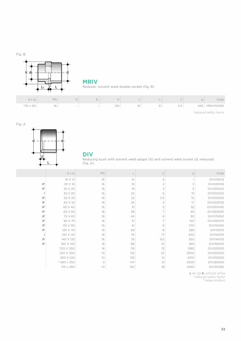
MRIVReducer: solvent weld double socket (fig. A)
*resale product
Fig. A
33
d x d1 PN L Z g Code
16 X 12 16 14 2 1 DIV016012IF 20 X 16 16 16 2 3 DIV020016IF 25 X 20 16 19 3 5 DIV025020
I 32 X 20 16 22 6 15 DIV032020IF 32 X 25 16 22 3.5 10 DIV032025IF 40 X 32 16 26 4 17 DIV040032IF 50 X 40 16 31 5 32 DIV050040IF 63 X 50 16 38 7 65 DIV063050IF 75 X 63 16 44 6 85 DIV075063IF 90 X 75 16 51 7 150 DIV090075IF 110 X 90 16 61 9 270 DIV110090IF 125 X 110 16 69 8 285 DIV125110
I 140 X 110 16 76 17 645 DIV140110IF 140 X 125 16 76 9.5 350 DIV140125IF 160 X 140 16 86 10 565 DIV160140
*225 X 200 16 119 13 1380 DIV225200250 X 200 10 132 25 3500 DIV250200250 X 225 10 132 12 2100 DIV250225
**280 x 250 4 147 15 2500 DIV280250315 x 280 10 165 18 4590 DIV315280
DIVReducing bush with solvent weld spigot (d) and solvent weld socket (d1 reduced) (fig. A)
I: IIP 122 F: AFNOR NF04*reduced safety factor
**resale product
d x d1 PN E E1 K L L1 Z g Code
*110 x 90 16 - - 130 61 51 4.5 555 MRIV110090
MRIVReducer: solvent weld double socket (fig. B)
*reduced safety factor
Fig. B
Fig. A
34
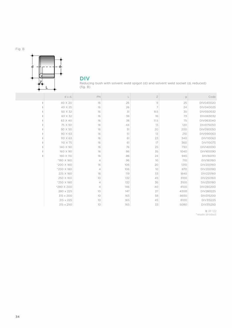
d x d1 PN L Z g Code
I 40 X 20 16 26 9 25 DIV040020I 40 X 25 16 26 7 24 DIV040025I 50 X 32 16 31 8.5 35 DIV050032I 63 X 32 16 38 16 73 DIV063032I 63 X 40 16 38 11.5 75 DIV063040I 75 X 50 16 44 13 120 DIV075050I 90 X 50 16 51 20 200 DIV090050I 90 X 63 16 51 13 210 DIV090063I 110 X 63 16 61 23 340 DIV110063I 110 X 75 16 61 17 360 DIV110075I 140 X 90 16 76 25 730 DIV140090I 160 X 90 16 86 35 1040 DIV160090I 160 X 110 16 86 24 945 DIV160110
*180 X 160 4 96 10 710 DIV180160*200 X 160 16 106 20 1310 DIV200160*200 X 180 4 106 10 870 DIV200180
225 X 160 16 119 33 1840 DIV225160250 X 160 10 132 45 3100 DIV250160
*250 X 180 4 132 36 3100 DIV250180*280 X 200 4 146 40 4100 DIV280200
280 x 225 10 147 27 4300 DIV280225315 x 200 10 165 58 8650 DIV315200315 x 225 10 165 45 8100 DIV315225315 x 250 10 165 33 5080 DIV315250
I: IIP 122*resale product
DIVReducing bush with solvent weld spigot (d) and solvent weld socket (d1 reduced) (fig. B)
Fig. B

35
d DN PN E F L Sp Z g Code
I 20 15 16 27 34 16 7 3.5 10 QPV020I 25 20 16 33 41 19 7 3 16 QPV025I 32 25 16 41 50 22 7 3 25 QPV032I 40 32 16 50 61 26 8 3 40 QPV040I 50 40 16 61 73 31 8 3 62 QPV050I 63 50 16 76 90 38 9 3 105 QPV063I 75 65 16 90 105 44 10 3 160 QPV075I 90 80 16 108 125 51 10 5 275 QPV090I 110 100 16 131 150 61 12 4 445 QPV110I 125 125 16 147 168 69 13 5 750 QPV125I 125 ***125 16 165 188 69 13 11 760 QPV125FKEI 140 125 16 165 188 76 14 5 790 QPV140
160 150 16 188 212 86 16 4.5 1140 QPV160200 ***200 16 248 273 106 30 24 2700 QPV200FKE200 *200 16 230 254 106 18 5.5 1840 QPV200355 **350 4 386 413 184 29 8 5400 QPV355400 **400 4 430 483 206 26 12 6500 QPV400450 **450 4 486 538 - 19 8 5200 QPV450500 **500 4 532 574 - 18 - 3000 QPV500
QPVFlat face stub according to DIN 8063 PN 10/16 with solvent weld socket
I: IIP 122*reduced safety factor
**resale product***special stubs for butterfly valves FK-FE
36
d DN PN E F L Sp Z g Code
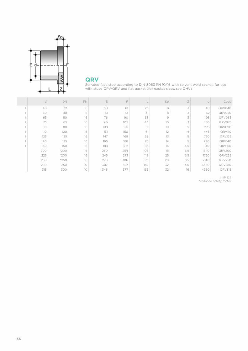
I 40 32 16 50 61 26 8 3 40 QRV040I 50 40 16 61 73 31 8 3 62 QRV050I 63 50 16 76 90 38 9 3 105 QRV063I 75 65 16 90 105 44 10 3 160 QRV075I 90 80 16 108 125 51 10 5 275 QRV090I 110 100 16 131 150 61 12 4 445 QRV110I 125 125 16 147 168 69 13 5 750 QRV125I 140 125 16 165 188 76 14 5 790 QRV140I 160 150 16 188 212 86 16 4.5 1140 QRV160
200 *200 16 230 254 106 18 5.5 1840 QRV200225 *200 16 245 273 119 25 5.5 1750 QRV225250 *250 16 270 306 131 20 8.5 2140 QRV250280 250 10 307 327 147 32 14.5 3650 QRV280315 300 10 346 377 165 32 16 4950 QRV315
QRVSerrated face stub according to DIN 8063 PN 10/16 with solvent weld socket, for use with stubs QPV/QRV and flat gasket (for gasket sizes, see QHV)
I: IIP 122*reduced safety factor
37
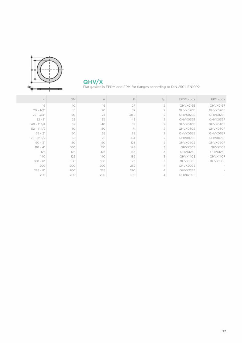
d DN A B Sp EPDM code FPM code
16 10 16 27 2 QHVX016E QHVX016F20 - 1/2” 15 20 32 2 QHVX020E QHVX020F25 - 3/4” 20 24 38.5 2 QHVX025E QHVX025F
32 - 1” 25 32 48 2 QHVX032E QHVX032F40 - 1” 1/4 32 40 59 2 QHVX040E QHVX040F50 - 1” 1/2 40 50 71 2 QHVX050E QHVX050F
63 - 2” 50 63 88 2 QHVX063E QHVX063F75 - 2” 1/2 65 75 104 2 QHVX075E QHVX075F
90 - 3” 80 90 123 2 QHVX090E QHVX090F110 - 4” 100 110 148 3 QHVX110E QHVX110F
125 125 125 166 3 QHVX125E QHVX125F140 125 140 186 3 QHVX140E QHVX140F
160 - 6” 150 160 211 3 QHVX160E QHVX160F200 200 200 252 4 QHVX200E -
225 - 8” 200 225 270 4 QHVX225E -250 250 250 305 4 QHVX250E -
QHV/X Flat gasket in EPDM and FPM for flanges according to DIN 2501, EN1092
38
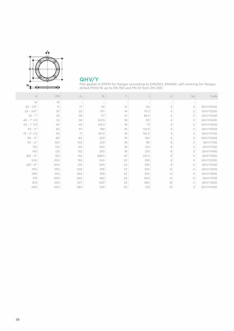
d DN A1 B1 F I U Sp Code
16 10 - - - - - - -20 - 1/2” 15 17 95 14 65 4 2 QHVY020E25 - 3/4” 20 22 107 14 76.3 4 2 QHVY025E
32 - 1” 25 28 117 14 86.5 4 2 QHVY032E40 - 1” 1/4 32 36 142.5 18 101 4 2 QHVY040E50 - 1” 1/2 40 45 153.3 18 111 4 2 QHVY050E
63 - 2” 50 57 168 18 125.5 4 2 QHVY063E75 - 2” 1/2 65 71 187.5 18 145.5 4 3 QHVY075E
90 - 3” 80 84 203 18 160 8 3 QHVY090E110 - 4” 100 102 223 18 181 8 3 QHVY110E
125 125 132 250 18 210 8 3 QHVY125E140 125 132 250 18 210 8 3 QHVY140E
160 - 6” 150 152 288.5 22 241.5 8 4 QHVY160E200 200 192 340 22 295 8 4 QHVY200E
225 - 8” 200 215 340 22 295 8 4 QHVY225E250 250 238 395 22 350 12 4 QHVY250E280 250 265 395 22 350 12 4 QHVY280E315 300 290 462 22 400 12 4 QHVY315E355 350 337 500 22 460 16 2 QHVY355E400 400 384 555 25 515 16 2 QHVY400E
QHV/YFlat gasket in EPDM for flanges according to DIN2501, EN1092, self-centring for flanges drilled PN10/16 up to DN 150 and PN 10 from DN 200
39
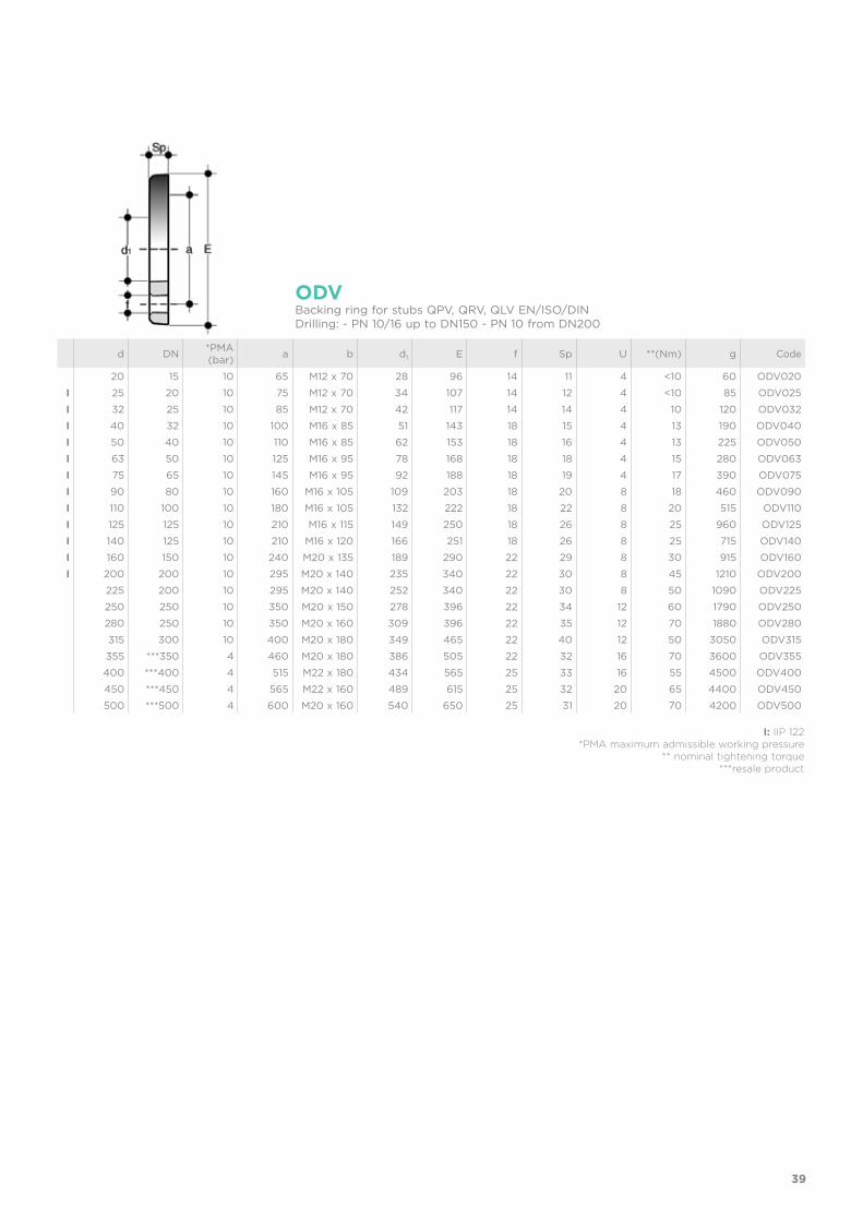
d DN *PMA(bar) a b d1 E f Sp U **(Nm) g Code
20 15 10 65 M12 x 70 28 96 14 11 4 <10 60 ODV020I 25 20 10 75 M12 x 70 34 107 14 12 4 <10 85 ODV025I 32 25 10 85 M12 x 70 42 117 14 14 4 10 120 ODV032I 40 32 10 100 M16 x 85 51 143 18 15 4 13 190 ODV040I 50 40 10 110 M16 x 85 62 153 18 16 4 13 225 ODV050I 63 50 10 125 M16 x 95 78 168 18 18 4 15 280 ODV063I 75 65 10 145 M16 x 95 92 188 18 19 4 17 390 ODV075I 90 80 10 160 M16 x 105 109 203 18 20 8 18 460 ODV090I 110 100 10 180 M16 x 105 132 222 18 22 8 20 515 ODV110I 125 125 10 210 M16 x 115 149 250 18 26 8 25 960 ODV125I 140 125 10 210 M16 x 120 166 251 18 26 8 25 715 ODV140I 160 150 10 240 M20 x 135 189 290 22 29 8 30 915 ODV160I 200 200 10 295 M20 x 140 235 340 22 30 8 45 1210 ODV200
225 200 10 295 M20 x 140 252 340 22 30 8 50 1090 ODV225250 250 10 350 M20 x 150 278 396 22 34 12 60 1790 ODV250280 250 10 350 M20 x 160 309 396 22 35 12 70 1880 ODV280315 300 10 400 M20 x 180 349 465 22 40 12 50 3050 ODV315355 ***350 4 460 M20 x 180 386 505 22 32 16 70 3600 ODV355400 ***400 4 515 M22 x 180 434 565 25 33 16 55 4500 ODV400450 ***450 4 565 M22 x 160 489 615 25 32 20 65 4400 ODV450500 ***500 4 600 M20 x 160 540 650 25 31 20 70 4200 ODV500
ODVBacking ring for stubs QPV, QRV, QLV EN/ISO/DINDrilling: - PN 10/16 up to DN150 - PN 10 from DN200
I: IIP 122*PMA maximum admissible working pressure
** nominal tightening torque***resale product
40
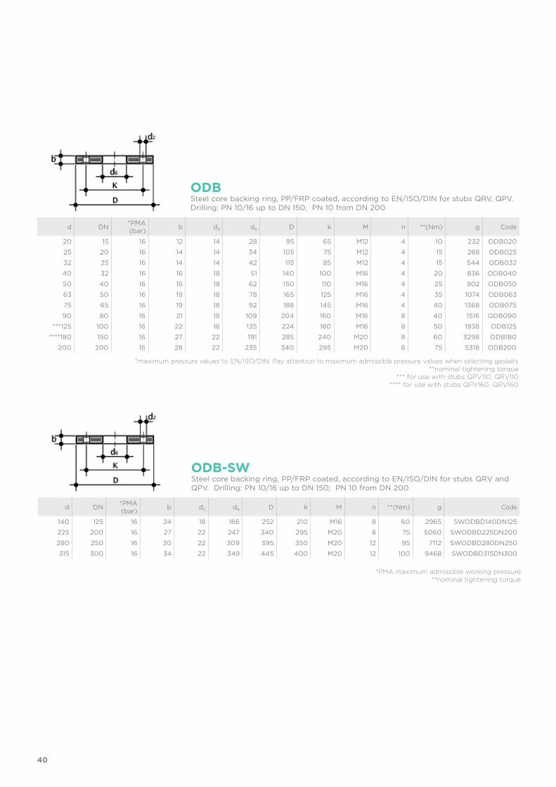
d DN *PMA(bar) b d2 d6 D k M n **(Nm) g Code
140 125 16 24 18 166 252 210 M16 8 60 2965 SWODBD140DN125225 200 16 27 22 247 340 295 M20 8 75 5060 SWODBD225DN200280 250 16 30 22 309 395 350 M20 12 95 7112 SWODBD280DN250315 300 16 34 22 349 445 400 M20 12 100 9468 SWODBD315DN300
ODB-SWSteel core backing ring, PP/FRP coated, according to EN/ISO/DIN for stubs QRV and QPV. Drilling: PN 10/16 up to DN 150; PN 10 from DN 200
*PMA maximum admissible working pressure**nominal tightening torque
d DN *PMA(bar) b d2 d6 D k M n **(Nm) g Code
20 15 16 12 14 28 95 65 M12 4 10 232 ODB02025 20 16 14 14 34 105 75 M12 4 15 288 ODB02532 25 16 14 14 42 115 85 M12 4 15 544 ODB03240 32 16 16 18 51 140 100 M16 4 20 836 ODB04050 40 16 16 18 62 150 110 M16 4 25 902 ODB05063 50 16 19 18 78 165 125 M16 4 35 1074 ODB06375 65 16 19 18 92 188 145 M16 4 40 1368 ODB07590 80 16 21 18 109 204 160 M16 8 40 1516 ODB090
***125 100 16 22 18 135 224 180 M16 8 50 1938 ODB125****180 150 16 27 22 191 285 240 M20 8 60 3298 ODB180
200 200 16 28 22 235 340 295 M20 8 75 5318 ODB200
ODBSteel core backing ring, PP/FRP coated, according to EN/ISO/DIN for stubs QRV, QPV. Drilling: PN 10/16 up to DN 150; PN 10 from DN 200
*maximum pressure values to EN/ISO/DIN. Pay attention to maximum admissible pressure values when selecting gaskets **nominal tightening torque *** for use with stubs QPV110, QRV110 **** for use with stubs QPV160, QRV160
41
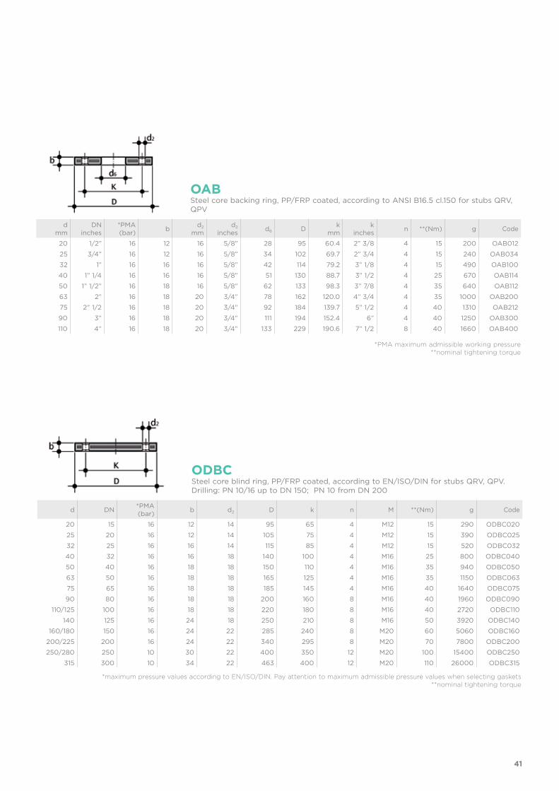
d DN *PMA(bar) b d2 D k n M **(Nm) g Code
20 15 16 12 14 95 65 4 M12 15 290 ODBC02025 20 16 12 14 105 75 4 M12 15 390 ODBC02532 25 16 16 14 115 85 4 M12 15 520 ODBC03240 32 16 16 18 140 100 4 M16 25 800 ODBC04050 40 16 18 18 150 110 4 M16 35 940 ODBC05063 50 16 18 18 165 125 4 M16 35 1150 ODBC06375 65 16 18 18 185 145 4 M16 40 1640 ODBC07590 80 16 18 18 200 160 8 M16 40 1960 ODBC090
110/125 100 16 18 18 220 180 8 M16 40 2720 ODBC110140 125 16 24 18 250 210 8 M16 50 3920 ODBC140
160/180 150 16 24 22 285 240 8 M20 60 5060 ODBC160200/225 200 16 24 22 340 295 8 M20 70 7800 ODBC200250/280 250 10 30 22 400 350 12 M20 100 15400 ODBC250
315 300 10 34 22 463 400 12 M20 110 26000 ODBC315
ODBCSteel core blind ring, PP/FRP coated, according to EN/ISO/DIN for stubs QRV, QPV. Drilling: PN 10/16 up to DN 150; PN 10 from DN 200
*maximum pressure values according to EN/ISO/DIN. Pay attention to maximum admissible pressure values when selecting gaskets **nominal tightening torque
dmm
DNinches
*PMA(bar) b d2
mmd2
inches d6 D kmm
kinches n **(Nm) g Code
20 1/2” 16 12 16 5/8” 28 95 60.4 2” 3/8 4 15 200 OAB01225 3/4” 16 12 16 5/8” 34 102 69.7 2” 3/4 4 15 240 OAB03432 1” 16 16 16 5/8” 42 114 79.2 3” 1/8 4 15 490 OAB10040 1” 1/4 16 16 16 5/8” 51 130 88.7 3” 1/2 4 25 670 OAB11450 1” 1/2” 16 18 16 5/8” 62 133 98.3 3” 7/8 4 35 640 OAB11263 2” 16 18 20 3/4” 78 162 120.0 4” 3/4 4 35 1000 OAB20075 2” 1/2 16 18 20 3/4” 92 184 139.7 5” 1/2 4 40 1310 OAB21290 3” 16 18 20 3/4” 111 194 152.4 6” 4 40 1250 OAB300110 4” 16 18 20 3/4” 133 229 190.6 7” 1/2 8 40 1660 OAB400
OABSteel core backing ring, PP/FRP coated, according to ANSI B16.5 cl.150 for stubs QRV, QPV
*PMA maximum admissible working pressure**nominal tightening torque
42
inches DN *PMA(bar) b d2
mmd2
inches D kmm
kinches n **(Nm) g Code
1/2” 15 16 12 16 5/8” 95 60.45 2” 3/8 4 15 200 OABC0123/4” 20 16 12 16 5/8” 102 69.85 2” 3/4 4 15 240 OABC034
1” 25 16 16 16 5/8” 114 79.25 3” 1/8 4 15 370 OABC1001” 1/4 32 16 16 16 5/8” 130 88.90 3” 1/2 4 25 530 OABC1141” 1/2 40 16 18 16 5/8” 133 98.55 3” 7/8 4 35 560 OABC112
2” 50 16 18 20 3/4” 162 120.65 4” 3/4 4 35 810 OABC2002” 1/2 65 16 18 20 3/4” 184 139.70 5” 1/2 4 40 1070 OABC212
3” 80 16 18 20 3/4” 194 152.40 6” 4 40 1030 OABC3004” 100 16 18 20 3/4” 229 190.50 7” 1/2 8 40 1570 OABC400
d DN *PMA(bar) a E f L Sp Z **(Nm) g Code
25 20 10 75 105 14 19 12 4.5 <10 105 FDV02532 25 10 85 115 14 22 14 4.5 10 150 FDV03240 32 10 100 140 18 26 15 4.5 13 230 FDV04050 40 10 110 150 18 31 16 4.5 13 280 FDV05063 50 10 125 163 18 38 18 4.5 15 390 FDV06375 65 10 145 185 18 44 19 5 17 525 FDV07590 80 10 160 200 18 51 20 7 18 710 FDV090110 100 10 180 220 18 61 22 8 20 955 FDV110
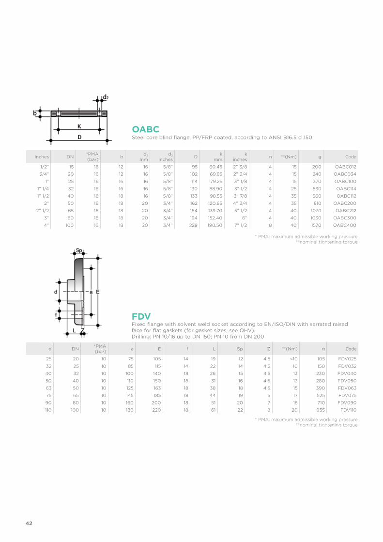
FDVFixed flange with solvent weld socket according to EN/ISO/DIN with serrated raised face for flat gaskets (for gasket sizes, see QHV).Drilling: PN 10/16 up to DN 150; PN 10 from DN 200
* PMA: maximum admissible working pressure **nominal tightening torque
* PMA: maximum admissible working pressure **nominal tightening torque
Steel core blind flange, PP/FRP coated, according to ANSI B16.5 cl.150 OABC
43
d x P2 x P1 PN H L g Code
12 x 14 x 12 16 56 12 6 AIV01201401216 x 18 x 16 16 60 14 12 AIV016018016
20 x 22 x 20 16 67 16 17 AIV02002202025 x 27 x 25 16 81 19 26 AIV02502702532 x 32 x 30 16 97 22 40 AIV03203203040 x 42 x 40 16 104 26 78 AIV04004204050 x 52 x 50 16 111 31 113 AIV05005205063 x 64 x 60 16 123 38 170 AIV063064060
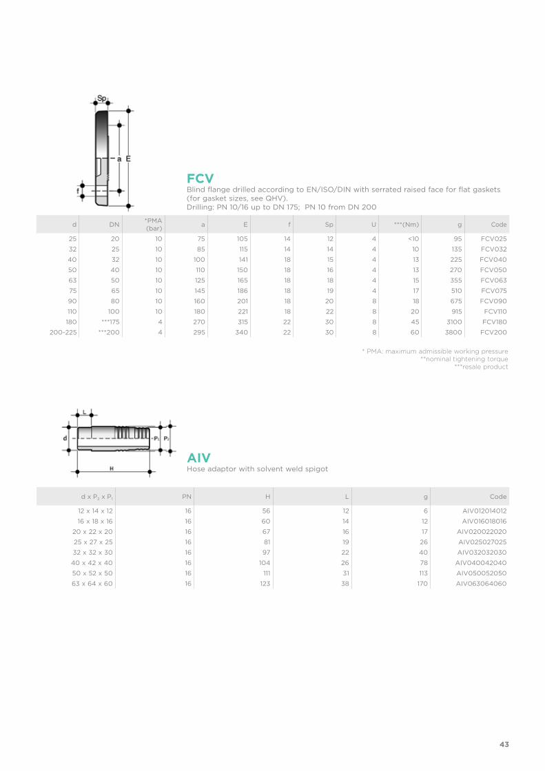
AIVHose adaptor with solvent weld spigot
d DN *PMA(bar) a E f Sp U ***(Nm) g Code
25 20 10 75 105 14 12 4 <10 95 FCV02532 25 10 85 115 14 14 4 10 135 FCV03240 32 10 100 141 18 15 4 13 225 FCV04050 40 10 110 150 18 16 4 13 270 FCV05063 50 10 125 165 18 18 4 15 355 FCV06375 65 10 145 186 18 19 4 17 510 FCV07590 80 10 160 201 18 20 8 18 675 FCV090110 100 10 180 221 18 22 8 20 915 FCV110180 ***175 4 270 315 22 30 8 45 3100 FCV180
200-225 ***200 4 295 340 22 30 8 60 3800 FCV200
FCVBlind flange drilled according to EN/ISO/DIN with serrated raised face for flat gaskets (for gasket sizes, see QHV).Drilling: PN 10/16 up to DN 175; PN 10 from DN 200
* PMA: maximum admissible working pressure**nominal tightening torque
***resale product
44
d a b C h I Code
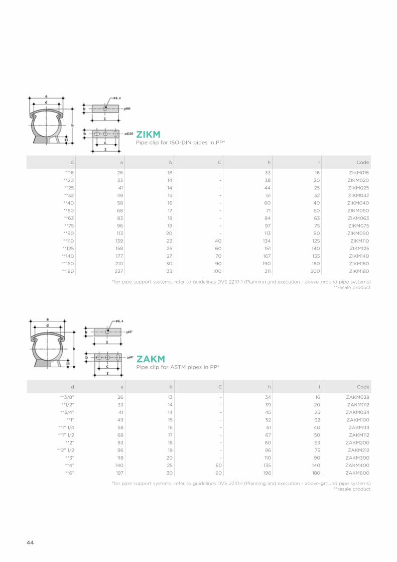
**16 26 18 - 33 16 ZIKM016**20 33 14 - 38 20 ZIKM020**25 41 14 - 44 25 ZIKM025**32 49 15 - 51 32 ZIKM032**40 58 16 - 60 40 ZIKM040**50 68 17 - 71 60 ZIKM050**63 83 18 - 84 63 ZIKM063**75 96 19 - 97 75 ZIKM075**90 113 20 - 113 90 ZIKM090**110 139 23 40 134 125 ZIKM110**125 158 25 60 151 140 ZIKM125**140 177 27 70 167 155 ZIKM140**160 210 30 90 190 180 ZIKM160**180 237 33 100 211 200 ZIKM180
ZIKMPipe clip for ISO-DIN pipes in PP*
*for pipe support systems, refer to guidelines DVS 2210-1 (Planning and execution - above-ground pipe systems) **resale product
*for pipe support systems, refer to guidelines DVS 2210-1 (Planning and execution - above-ground pipe systems)**resale product
d a b C h I Code
**3/8” 26 13 - 34 16 ZAKM038**1/2” 33 14 - 39 20 ZAKM012**3/4” 41 14 - 45 25 ZAKM034
**1” 49 15 - 52 32 ZAKM100**1” 1/4 58 16 - 61 40 ZAKM114**1” 1/2 68 17 - 67 50 ZAKM112
**2” 83 18 - 80 63 ZAKM200**2” 1/2 96 19 - 96 75 ZAKM212
**3” 118 20 - 110 90 ZAKM300**4” 140 25 60 135 140 ZAKM400**6” 197 30 90 196 180 ZAKM600
ZAKMPipe clip for ASTM pipes in PP*
45
*for pipe support systems, refer to guidelines DVS 2210-1 (Planning and execution - above-ground pipe systems)**resale product
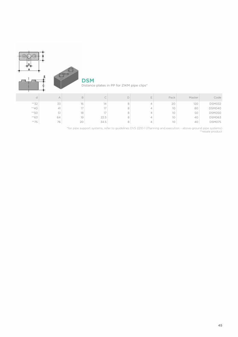
d A B C D E Pack Master Code
**32 33 16 14 8 4 20 120 DSM032**40 41 17 17 8 4 10 80 DSM040**50 51 18 17 8 4 10 50 DSM050**63 64 19 22.5 8 4 10 40 DSM063**75 76 20 34.5 8 4 10 40 DSM075
DSMDistance plates in PP for ZIKM pipe clips*
46
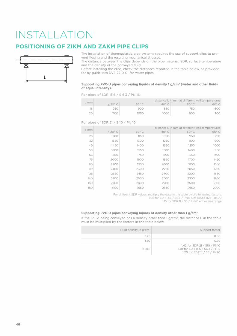
Supporting PVC-U pipes conveying liquids of density 1 g/cm3 (water and other fluids of equal intensity).
For pipes of SDR 13.6 / S 6.3 / PN 16:
For pipes of SDR 21 / S 10 / PN 10:
Supporting PVC-U pipes conveying liquids of density other than 1 g/cm3. If the liquid being conveyed has a density other than 1 g/cm3, the distance L in the table must be multiplied by the factors in the table below.
INSTALLATIONThe installation of thermoplastic pipe systems requires the use of support clips to pre-vent flexing and the resulting mechanical stresses.The distance between the clips depends on the pipe material, SDR, surface temperature and the density of the conveyed fluid.Before installing the clips, check the distances reported in the table below, as provided for by guidelines DVS 2210-01 for water pipes.
d mmdistance L in mm at different wall temperatures
< 20° C 30° C 40° C 50° C 60° C16 950 900 850 750 600
20 1100 1050 1000 900 700
d mmdistance L in mm at different wall temperatures
< 20° C 30° C 40° C 50° C 60° C25 1200 1150 1050 950 750
32 1350 1300 1250 1100 900
40 1450 1400 1350 1250 1000
50 1600 1550 1500 1400 1150
63 1800 1750 1700 1550 1300
75 2000 1900 1850 1700 1450
90 2200 2100 2000 1850 1550
110 2400 2300 2250 2050 1750
125 2550 2450 2400 2200 1850
140 2700 2600 2500 2300 1950
160 2900 2800 2700 2500 2100
180 3100 2950 2850 2650 2200
Fluid density in g/cm3 Support factor
1.25 0.96
1.50 0.92
< 0.011.42 for SDR 21 / S10 / PN10
1.30 for SDR 13.6 / S6.3 / PN161.20 for SDR 11 / S5 / PN20
POSITIONING OF ZIKM AND ZAKM PIPE CLIPS
For different SDR values, multiply the data in the table by the following factors:1.08 for SDR 13.6 / S6.3 / PN16 size range d25 - d400
1.15 for SDR 11 / S5 / PN20 entire size range

47

ISO-BSP FITTINGSPVC-U
Adaptor fittings
50
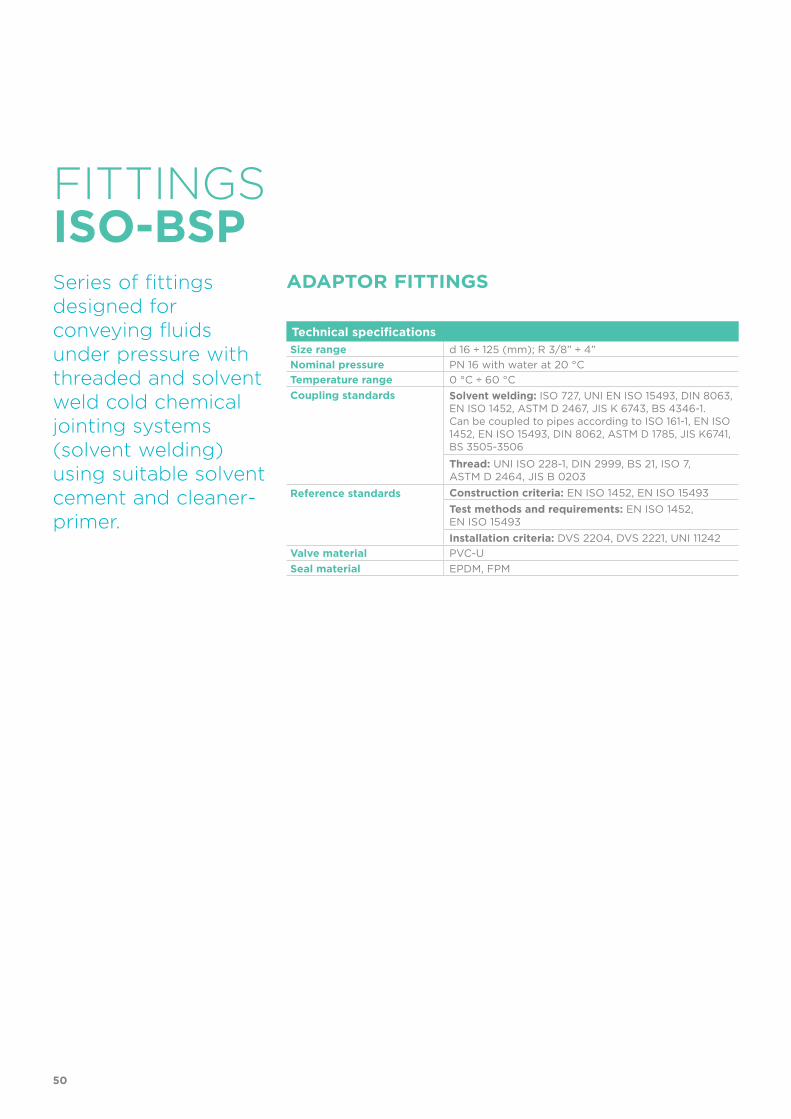
Technical specificationsSize range d 16 ÷ 125 (mm); R 3/8” ÷ 4”Nominal pressure PN 16 with water at 20 °CTemperature range 0 °C ÷ 60 °CCoupling standards Solvent welding: ISO 727, UNI EN ISO 15493, DIN 8063,
EN ISO 1452, ASTM D 2467, JIS K 6743, BS 4346-1. Can be coupled to pipes according to ISO 161-1, EN ISO 1452, EN ISO 15493, DIN 8062, ASTM D 1785, JIS K6741, BS 3505-3506Thread: UNI ISO 228-1, DIN 2999, BS 21, ISO 7, ASTM D 2464, JIS B 0203
Reference standards Construction criteria: EN ISO 1452, EN ISO 15493Test methods and requirements: EN ISO 1452, EN ISO 15493Installation criteria: DVS 2204, DVS 2221, UNI 11242
Valve material PVC-USeal material EPDM, FPM
FITTINGS
Series of fittings designed for conveying fluids under pressure with threaded and solvent weld cold chemical jointing systems (solvent welding) using suitable solvent cement and cleaner-primer.
ADAPTOR FITTINGS
ISO-BSP
51
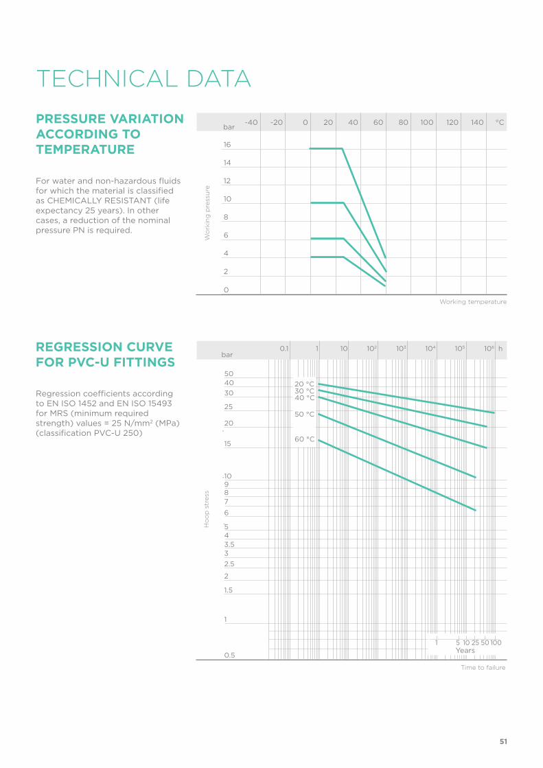
REGRESSION CURVE FOR PVC-U FITTINGS
Ho
op
str
ess
Time to failure
bar0.1 1 10 102 103 104 105 106 h
20
25
304050
15
10
0.5
1
1.5
2
2.533.545
6789
20 °C30 °C40 °C
50 °C
60 °C
1 5 10 25 50 100Years
TECHNICAL DATA
-40 -20 0 20 40 60 80 100 120 140 °C
16
14
12
10
8
6
4
2
0
Wo
rkin
g p
ress
ure
Working temperature
barPRESSURE VARIATION ACCORDING TO TEMPERATURE
For water and non-hazardous fluids for which the material is classified as CHEMICALLY RESISTANT (life expectancy 25 years). In other cases, a reduction of the nominal pressure PN is required.
Regression coefficients according to EN ISO 1452 and EN ISO 15493 for MRS (minimum required strength) values = 25 N/mm2 (MPa) (classification PVC-U 250)

52
The information in this leaflet is provided in good faith. FIP will not be held liable for technical data not originating directly from recognised international standards. The company reserves the right to carry out any modifications. Products must be installed and maintained by qualified personnel.
SAFETY FACTORS
The table reports the safety factors for each pressure class as a function of time.
Nominal pressure PN must be understood as being the standard pressure used for calculating and selecting the required fittings. In order to be able to comply with the safety factors, the maximum continuous working pressure at 20° C when conveying water must be the same as the nominal pressure values.Unless otherwise specified, the nominal pressures are as follows:• solvent weld fittings from d 12 to d 225 PN 16 from d 250 to d 315 PN 10• adaptor fittings from d 16 to d 110 PN 16• threaded fittings from R 3/8” to R 4” up to PN 16.
Some of the fittings in the series are sold as PN16 with a reduced safety factor compared to that specified by ISO standards.
1h 1000h 50 years T
10 6.72 5.12 4
16 4.2 3.2 2.5
16* 3.3 2.5 2*with reduced safety factor
Pe (bar)
53
DIMENSIONS
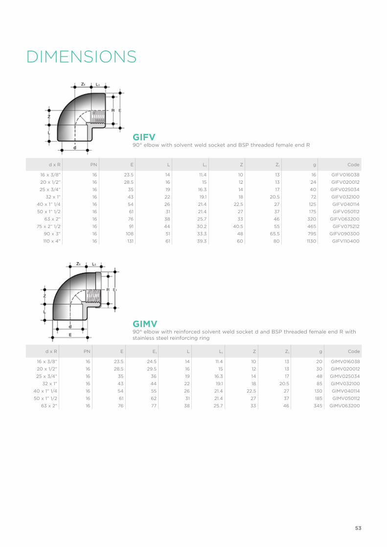
d x R PN E L L1 Z Z1 g Code
16 x 3/8” 16 23.5 14 11.4 10 13 16 GIFV01603820 x 1/2” 16 28.5 16 15 12 13 24 GIFV02001225 x 3/4” 16 35 19 16.3 14 17 40 GIFV025034
32 x 1” 16 43 22 19.1 18 20.5 72 GIFV03210040 x 1” 1/4 16 54 26 21.4 22.5 27 125 GIFV04011450 x 1” 1/2 16 61 31 21.4 27 37 175 GIFV050112
63 x 2” 16 76 38 25.7 33 46 320 GIFV06320075 x 2” 1/2 16 91 44 30.2 40.5 55 465 GIFV075212
90 x 3” 16 108 51 33.3 48 65.5 795 GIFV090300110 x 4” 16 131 61 39.3 60 80 1130 GIFV110400
GIFV90° elbow with solvent weld socket and BSP threaded female end R
d x R PN E E1 L L1 Z Z1 g Code
16 x 3/8” 16 23.5 24.5 14 11.4 10 13 20 GIMV01603820 x 1/2” 16 28.5 29.5 16 15 12 13 30 GIMV02001225 x 3/4” 16 35 36 19 16.3 14 17 48 GIMV025034
32 x 1” 16 43 44 22 19.1 18 20.5 85 GIMV03210040 x 1” 1/4 16 54 55 26 21.4 22.5 27 130 GIMV04011450 x 1” 1/2 16 61 62 31 21.4 27 37 185 GIMV050112
63 x 2” 16 76 77 38 25.7 33 46 345 GIMV063200
GIMV90° elbow with reinforced solvent weld socket d and BSP threaded female end R with stainless steel reinforcing ring
54
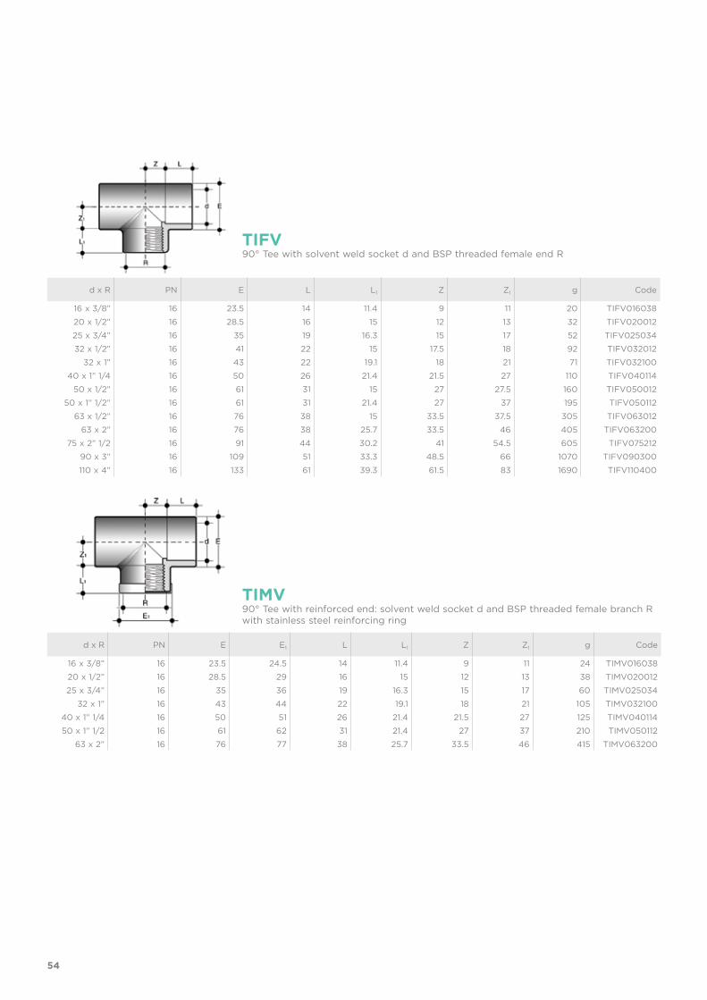
d x R PN E L L1 Z Z1 g Code
16 x 3/8” 16 23.5 14 11.4 9 11 20 TIFV01603820 x 1/2” 16 28.5 16 15 12 13 32 TIFV02001225 x 3/4” 16 35 19 16.3 15 17 52 TIFV02503432 x 1/2” 16 41 22 15 17.5 18 92 TIFV032012
32 x 1” 16 43 22 19.1 18 21 71 TIFV03210040 x 1” 1/4 16 50 26 21.4 21.5 27 110 TIFV040114
50 x 1/2” 16 61 31 15 27 27.5 160 TIFV05001250 x 1” 1/2” 16 61 31 21.4 27 37 195 TIFV050112
63 x 1/2” 16 76 38 15 33.5 37.5 305 TIFV06301263 x 2” 16 76 38 25.7 33.5 46 405 TIFV063200
75 x 2” 1/2 16 91 44 30.2 41 54.5 605 TIFV07521290 x 3” 16 109 51 33.3 48.5 66 1070 TIFV090300110 x 4” 16 133 61 39.3 61.5 83 1690 TIFV110400
TIFV90° Tee with solvent weld socket d and BSP threaded female end R
d x R PN E E1 L L1 Z Z1 g Code
16 x 3/8” 16 23.5 24.5 14 11.4 9 11 24 TIMV01603820 x 1/2” 16 28.5 29 16 15 12 13 38 TIMV02001225 x 3/4” 16 35 36 19 16.3 15 17 60 TIMV025034
32 x 1” 16 43 44 22 19.1 18 21 105 TIMV03210040 x 1” 1/4 16 50 51 26 21.4 21.5 27 125 TIMV04011450 x 1” 1/2 16 61 62 31 21.4 27 37 210 TIMV050112
63 x 2” 16 76 77 38 25.7 33.5 46 415 TIMV063200
TIMV90° Tee with reinforced end: solvent weld socket d and BSP threaded female branch R with stainless steel reinforcing ring
55
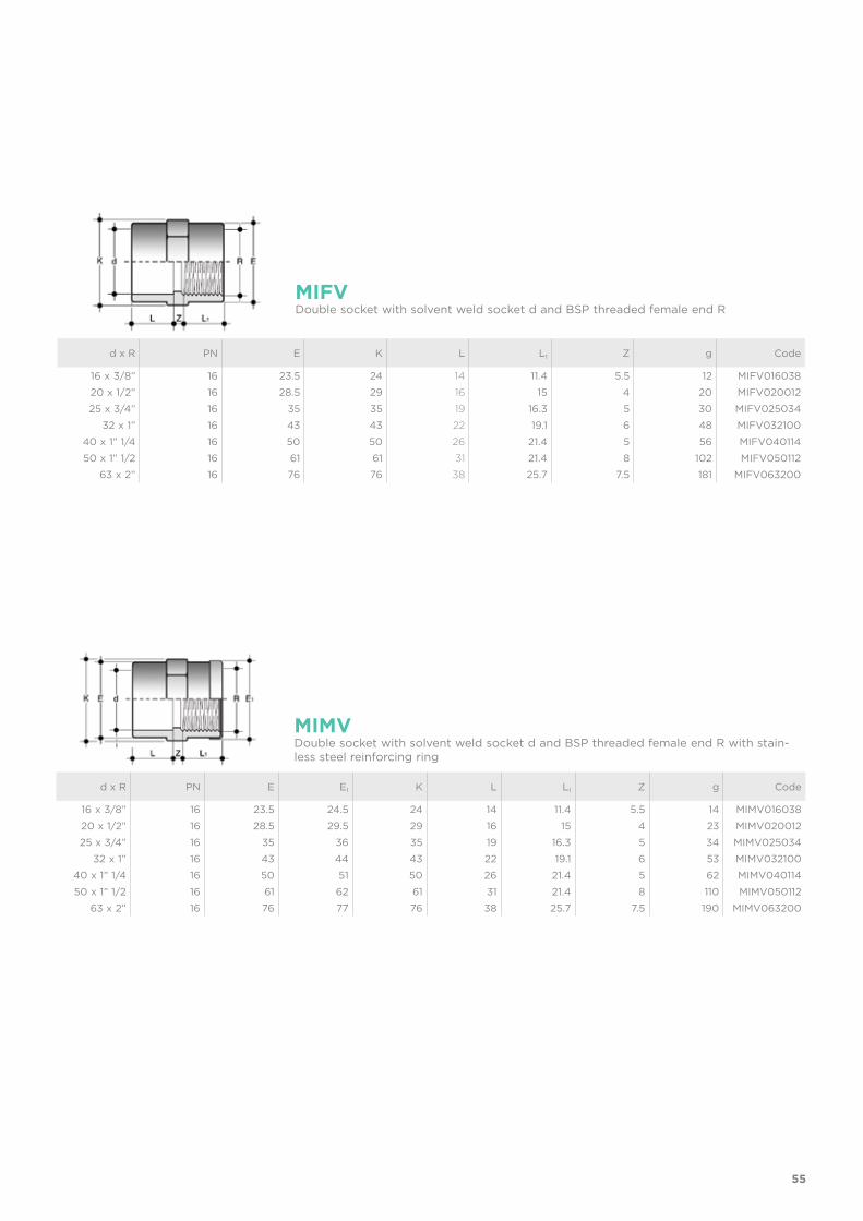
d x R PN E K L L1 Z g Code
16 x 3/8” 16 23.5 24 14 11.4 5.5 12 MIFV01603820 x 1/2” 16 28.5 29 16 15 4 20 MIFV02001225 x 3/4” 16 35 35 19 16.3 5 30 MIFV025034
32 x 1” 16 43 43 22 19.1 6 48 MIFV03210040 x 1” 1/4 16 50 50 26 21.4 5 56 MIFV04011450 x 1” 1/2 16 61 61 31 21.4 8 102 MIFV050112
63 x 2” 16 76 76 38 25.7 7.5 181 MIFV063200
MIFVDouble socket with solvent weld socket d and BSP threaded female end R
d x R PN E E1 K L L1 Z g Code
16 x 3/8” 16 23.5 24.5 24 14 11.4 5.5 14 MIMV01603820 x 1/2” 16 28.5 29.5 29 16 15 4 23 MIMV02001225 x 3/4” 16 35 36 35 19 16.3 5 34 MIMV025034
32 x 1” 16 43 44 43 22 19.1 6 53 MIMV03210040 x 1” 1/4 16 50 51 50 26 21.4 5 62 MIMV04011450 x 1” 1/2 16 61 62 61 31 21.4 8 110 MIMV050112
63 x 2” 16 76 77 76 38 25.7 7.5 190 MIMV063200
MIMVDouble socket with solvent weld socket d and BSP threaded female end R with stain-less steel reinforcing ring
56
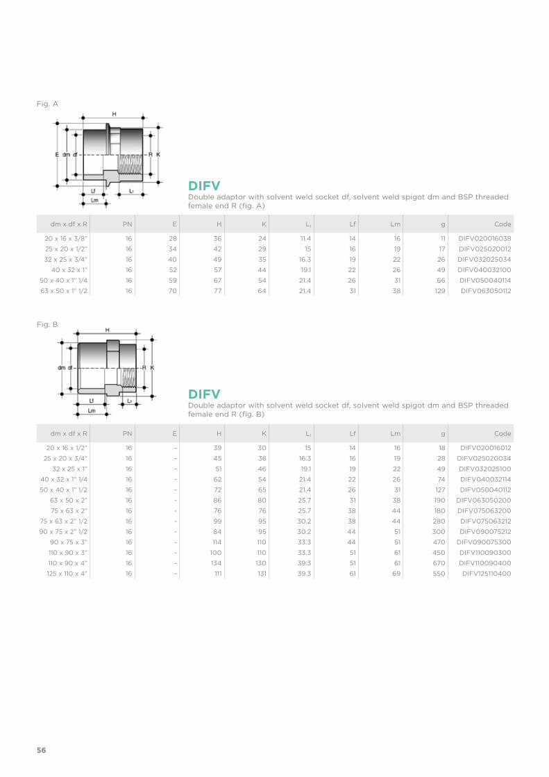
dm x df x R PN E H K L1 Lf Lm g Code
20 x 16 x 3/8” 16 28 36 24 11.4 14 16 11 DIFV02001603825 x 20 x 1/2” 16 34 42 29 15 16 19 17 DIFV02502001232 x 25 x 3/4” 16 40 49 35 16.3 19 22 26 DIFV032025034
40 x 32 x 1” 16 52 57 44 19.1 22 26 49 DIFV04003210050 x 40 x 1” 1/4 16 59 67 54 21.4 26 31 66 DIFV05004011463 x 50 x 1” 1/2 16 70 77 64 21.4 31 38 129 DIFV063050112
dm x df x R PN E H K L1 Lf Lm g Code
20 x 16 x 1/2” 16 - 39 30 15 14 16 18 DIFV02001601225 x 20 x 3/4” 16 - 45 36 16.3 16 19 28 DIFV025020034
32 x 25 x 1” 16 - 51 46 19.1 19 22 49 DIFV03202510040 x 32 x 1” 1/4 16 - 62 54 21.4 22 26 74 DIFV04003211450 x 40 x 1” 1/2 16 - 72 65 21.4 26 31 127 DIFV050040112
63 x 50 x 2” 16 - 86 80 25.7 31 38 190 DIFV06305020075 x 63 x 2” 16 - 76 76 25.7 38 44 180 DIFV075063200
75 x 63 x 2” 1/2 16 - 99 95 30.2 38 44 280 DIFV07506321290 x 75 x 2” 1/2 16 - 84 95 30.2 44 51 300 DIFV090075212
90 x 75 x 3” 16 - 114 110 33.3 44 51 470 DIFV090075300110 x 90 x 3” 16 - 100 110 33.3 51 61 450 DIFV110090300110 x 90 x 4” 16 - 134 130 39.3 51 61 670 DIFV110090400125 x 110 x 4” 16 - 111 131 39.3 61 69 550 DIFV125110400
DIFV
DIFV
Double adaptor with solvent weld socket df, solvent weld spigot dm and BSP threaded female end R (fig. A)
Double adaptor with solvent weld socket df, solvent weld spigot dm and BSP threaded female end R (fig. B)
Fig. A
Fig. B
57
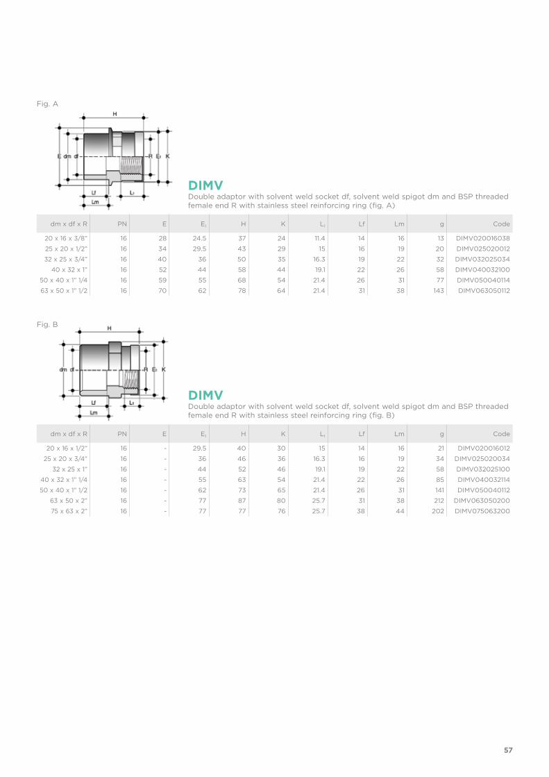
dm x df x R PN E E1 H K L1 Lf Lm g Code
20 x 16 x 3/8” 16 28 24.5 37 24 11.4 14 16 13 DIMV02001603825 x 20 x 1/2” 16 34 29.5 43 29 15 16 19 20 DIMV02502001232 x 25 x 3/4” 16 40 36 50 35 16.3 19 22 32 DIMV032025034
40 x 32 x 1” 16 52 44 58 44 19.1 22 26 58 DIMV04003210050 x 40 x 1” 1/4 16 59 55 68 54 21.4 26 31 77 DIMV05004011463 x 50 x 1” 1/2 16 70 62 78 64 21.4 31 38 143 DIMV063050112
dm x df x R PN E E1 H K L1 Lf Lm g Code
20 x 16 x 1/2” 16 - 29.5 40 30 15 14 16 21 DIMV02001601225 x 20 x 3/4” 16 - 36 46 36 16.3 16 19 34 DIMV025020034
32 x 25 x 1” 16 - 44 52 46 19.1 19 22 58 DIMV03202510040 x 32 x 1” 1/4 16 - 55 63 54 21.4 22 26 85 DIMV04003211450 x 40 x 1” 1/2 16 - 62 73 65 21.4 26 31 141 DIMV050040112
63 x 50 x 2” 16 - 77 87 80 25.7 31 38 212 DIMV06305020075 x 63 x 2” 16 - 77 77 76 25.7 38 44 202 DIMV075063200
DIMV
DIMV
Double adaptor with solvent weld socket df, solvent weld spigot dm and BSP threaded female end R with stainless steel reinforcing ring (fig. A)
Double adaptor with solvent weld socket df, solvent weld spigot dm and BSP threaded female end R with stainless steel reinforcing ring (fig. B)
Fig. A
Fig. B
58
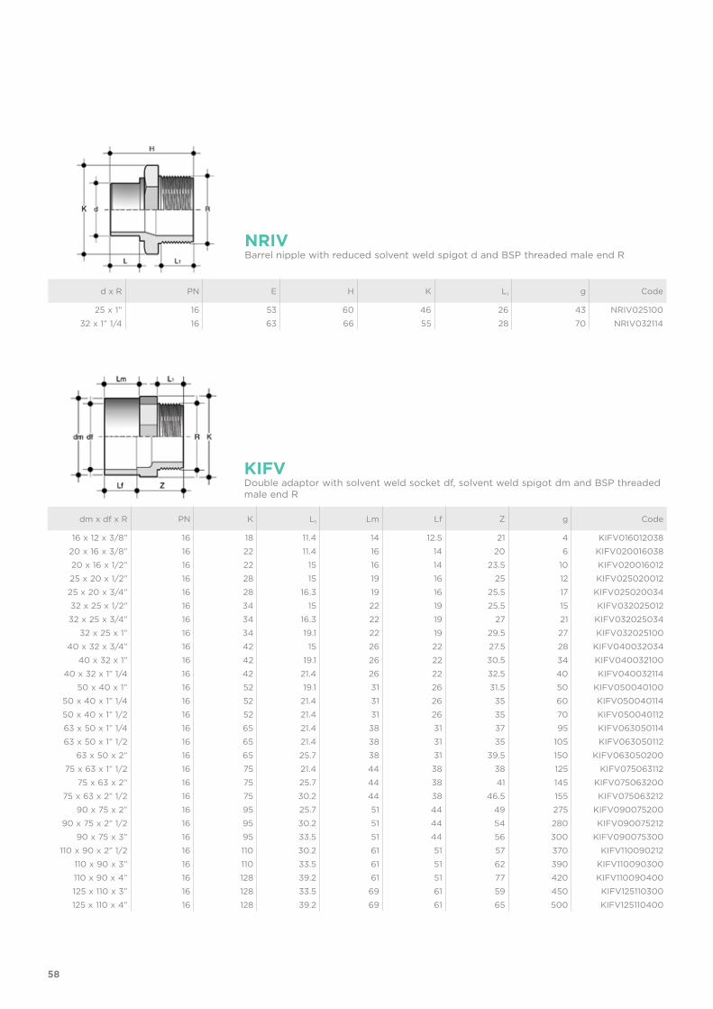
dm x df x R PN K L1 Lm Lf Z g Code
16 x 12 x 3/8” 16 18 11.4 14 12.5 21 4 KIFV01601203820 x 16 x 3/8” 16 22 11.4 16 14 20 6 KIFV02001603820 x 16 x 1/2” 16 22 15 16 14 23.5 10 KIFV02001601225 x 20 x 1/2” 16 28 15 19 16 25 12 KIFV02502001225 x 20 x 3/4” 16 28 16.3 19 16 25.5 17 KIFV02502003432 x 25 x 1/2” 16 34 15 22 19 25.5 15 KIFV03202501232 x 25 x 3/4” 16 34 16.3 22 19 27 21 KIFV032025034
32 x 25 x 1” 16 34 19.1 22 19 29.5 27 KIFV03202510040 x 32 x 3/4” 16 42 15 26 22 27.5 28 KIFV040032034
40 x 32 x 1” 16 42 19.1 26 22 30.5 34 KIFV04003210040 x 32 x 1” 1/4 16 42 21.4 26 22 32.5 40 KIFV040032114
50 x 40 x 1” 16 52 19.1 31 26 31.5 50 KIFV05004010050 x 40 x 1” 1/4 16 52 21.4 31 26 35 60 KIFV05004011450 x 40 x 1” 1/2 16 52 21.4 31 26 35 70 KIFV05004011263 x 50 x 1” 1/4 16 65 21.4 38 31 37 95 KIFV06305011463 x 50 x 1” 1/2 16 65 21.4 38 31 35 105 KIFV063050112
63 x 50 x 2” 16 65 25.7 38 31 39.5 150 KIFV06305020075 x 63 x 1” 1/2 16 75 21.4 44 38 38 125 KIFV075063112
75 x 63 x 2” 16 75 25.7 44 38 41 145 KIFV07506320075 x 63 x 2” 1/2 16 75 30.2 44 38 46.5 155 KIFV075063212
90 x 75 x 2” 16 95 25.7 51 44 49 275 KIFV09007520090 x 75 x 2” 1/2 16 95 30.2 51 44 54 280 KIFV090075212
90 x 75 x 3” 16 95 33.5 51 44 56 300 KIFV090075300110 x 90 x 2” 1/2 16 110 30.2 61 51 57 370 KIFV110090212
110 x 90 x 3” 16 110 33.5 61 51 62 390 KIFV110090300110 x 90 x 4” 16 128 39.2 61 51 77 420 KIFV110090400125 x 110 x 3” 16 128 33.5 69 61 59 450 KIFV125110300125 x 110 x 4” 16 128 39.2 69 61 65 500 KIFV125110400
KIFVDouble adaptor with solvent weld socket df, solvent weld spigot dm and BSP threaded male end R
d x R PN E H K L1 g Code
25 x 1” 16 53 60 46 26 43 NRIV02510032 x 1” 1/4 16 63 66 55 28 70 NRIV032114
NRIVBarrel nipple with reduced solvent weld spigot d and BSP threaded male end R

59
d x R R1 PN E H L L1 Z g Code
16 x 3/8” 3/4” 16 33 41 14 11.4 15.6 22 BIFV016038E20 x 1/2” 1” 16 41 45 16 15 14 35 BIFV020012E25 x 3/4” 1” 1/4 16 50 51 19 16.3 15.7 62 BIFV025034E
32 x 1” 1” 1/2 16 58 57 22 19.1 15.9 85 BIFV032100E40 x 1” 1/4 2” 16 72 67 26 21.4 19.6 145 BIFV040114E50 x 1” 1/2 2” 1/4 16 79 72 31 21.4 19.6 180 BIFV050112E
63 x 2” 2” 3/4 16 98 88 38 25.7 24 315 BIFV063200E75 x 2” 1/2 3” 1/2 10 120 116 44 30.2 34.8 630 BIFV075212E
90 x 3” 4” 10 135 125 51 33.3 40.7 810 BIFV090300E110 x 4” 5” 10 163 145 61 39.3 44.7 1350 BIFV110400E
BIFVUnion with solvent weld socket d and BSP threaded female end R with O-Ring in EPDM
d x R R1 PN E H K L L1 Z g Code
50 x 1” 1/2 2” 1/4 16 79 98 53 31 21.4 45.6 200 BIRV050112E50 x 2” 2” 1/4 16 79 102 53 31 25.7 45.3 220 BIRV050200E63 x 2” 2” 3/4 16 98 116 67 38 25.7 52.3 380 BIRV063200E
BIRVUnion with fixed BSP threaded male end and O-Ring in EPDM
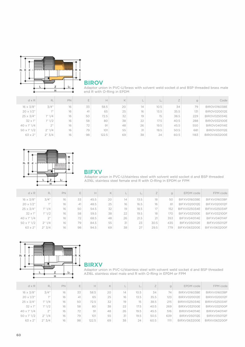
BIFOVAdaptor union in PVC-U/brass with solvent weld socket d and BSP threaded brass female end R with O-Ring in EPDM
d x R R1 PN E H K L L1 Z g Code
16 x 3/8” 3/4” 16 33 45.5 20 14 13.5 18 53 BIFOV016038E20 x 1/2” 1” 16 41 48.5 25 16 16.5 16 86 BIFOV020012E25 x 3/4” 1” 1/4 16 50 54.5 32 19 18.5 17 161 BIFOV025034E
32 x 1” 1” 1/2 16 58 59.5 38 22 19.5 18 181 BIFOV032100E40 x 1” 1/4 2” 16 72 68.5 48 26 21.5 21 373 BIFOV040114E50 x 1” 1/2 2” 1/4 16 79 84.5 55 31 23 24.5 460 BIFOV050112E
63 x 2” 2” 3/4 16 98 94.5 69 38 27 29.5 824 BIFOV063200E
60
BIROV
BIRXV
Adaptor union in PVC-U/brass with solvent weld socket d and BSP threaded brass male end R with O-Ring in EPDM
Adaptor union in PVC-U/stainless steel with solvent weld socket d and BSP threaded A316L stainless steel male end R with O-Ring in EPDM or FPM
d x R R1 PN E H K L L1 Z g Code
16 x 3/8” 3/4” 16 33 58.5 20 14 10.5 34 79 BIROV016038E20 x 1/2” 1” 16 41 65 25 16 13.5 35.5 131 BIROV020012E25 x 3/4” 1” 1/4 16 50 72.5 32 19 15 38.5 229 BIROV025034E
32 x 1” 1” 1/2 16 58 80 38 22 17.5 40.5 288 BIROV032100E40 x 1” 1/4 2” 16 72 91 48 26 19.5 45.5 550 BIROV040114E50 x 1” 1/2 2” 1/4 16 79 101 55 31 19.5 50.5 681 BIROV050112E
63 x 2” 2” 3/4 16 98 122.5 69 38 24 60.5 1183 BIROV063200E
d x R R1 PN E H K L L1 Z g EPDM code FPM code
16 x 3/8” 3/4” 16 33 58.5 20 14 10.5 34 74 BIRXV016038E BIRXV016038F20 x 1/2” 1” 16 41 65 25 16 13.5 35.5 123 BIRXV020012E BIRXV020012F25 x 3/4” 1” 1/4 16 50 72.5 32 19 15 38.5 215 BIRXV025034E BIRXV025034F
32 x 1” 1” 1/2 16 58 80 38 22 17.5 40.5 269 BIRXV032100E BIRXV032100F40 x 1” 1/4 2” 16 72 91 48 26 19.5 45.5 516 BIRXV040114E BIRXV040114F50 x 1” 1/2 2” 1/4 16 79 101 55 31 19.5 50.5 639 BIRXV050112E BIRXV050112F
63 x 2” 2” 3/4 16 98 122.5 69 38 24 60.5 1111 BIRXV063200E BIRXV063200F
BIFXVAdaptor union in PVC-U/stainless steel with solvent weld socket d and BSP threaded A316L stainless steel female end R with O-Ring in EPDM or FPM
d x R R1 PN E H K L L1 Z g EPDM code FPM code
16 x 3/8” 3/4” 16 33 45.5 20 14 13.5 18 50 BIFXV016038E BIFXV016038F20 x 1/2” 1” 16 41 48.5 25 16 16.5 16 81 BIFXV020012E BIFXV020012F25 x 3/4” 1” 1/4 16 50 54.5 32 19 18.5 17 152 BIFXV025034E BIFXV025034F
32 x 1” 1” 1/2 16 58 59.5 38 22 19.5 18 170 BIFXV032100E BIFXV032100F40 x 1” 1/4 2” 16 72 68.5 48 26 21.5 21 353 BIFXV040114E BIFXV040114F50 x 1” 1/2 2” 1/4 16 79 84.5 55 31 23 30.5 435 BIFXV050112E BIFXV050112F
63 x 2” 2” 3/4 16 98 94.5 69 38 27 29.5 779 BIFXV063200E BIFXV063200F
61
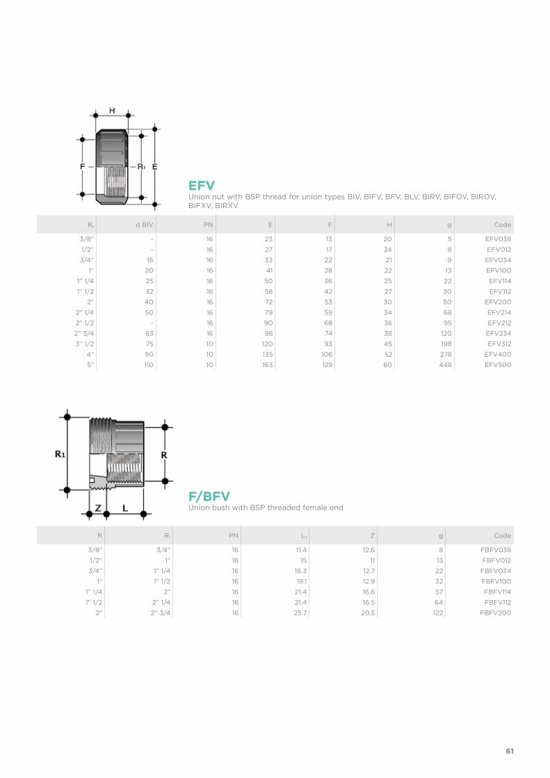
R1 d BIV PN E F H g Code
3/8” - 16 23 13 20 5 EFV0381/2” - 16 27 17 24 8 EFV0123/4” 16 16 33 22 21 9 EFV034
1” 20 16 41 28 22 13 EFV1001” 1/4 25 16 50 36 25 22 EFV1141” 1/2 32 16 58 42 27 30 EFV112
2” 40 16 72 53 30 50 EFV2002” 1/4 50 16 79 59 34 68 EFV2142” 1/2 - 16 90 68 36 95 EFV2122” 3/4 63 16 98 74 38 120 EFV2343” 1/2 75 10 120 93 45 198 EFV312
4” 90 10 135 106 52 278 EFV4005” 110 10 163 129 60 448 EFV500
EFVUnion nut with BSP thread for union types BIV, BIFV, BFV, BLV, BIRV, BIFOV, BIROV, BIFXV, BIRXV.
R R1 PN L1 Z g Code
3/8” 3/4” 16 11.4 12.6 8 FBFV0381/2” 1” 16 15 11 13 FBFV0123/4” 1” 1/4 16 16.3 12.7 22 FBFV034
1” 1” 1/2 16 19.1 12.9 32 FBFV1001” 1/4 2” 16 21.4 16.6 57 FBFV1141” 1/2 2” 1/4 16 21.4 16.5 64 FBFV112
2” 2” 3/4 16 25.7 20.5 122 FBFV200
F/BFVUnion bush with BSP threaded female end
62
d R1 PN L Z g Code
16 3/4” 16 14 10 9 FBIV01620 1” 16 16 10 13 FBIV02025 1” 1/4 16 19 10 25 FBIV02532 1” 1/2 16 22 10 31 FBIV03240 2” 16 26 12 58 FBIV04050 2” 1/4 16 31 14 63 FBIV05063 2” 3/4 16 38 19 119 FBIV06375 3” 1/2 10 44 18 230 FBIV07590 4” 10 51 18 290 FBIV090110 5” 10 61 18 500 FBIV110
F/BIVUnion bush for solvent welding, metric series
R R1 PN L1 g Code
1” 1/2 2” 1/4 16 22.5 100 FBRV1122142” 2” 1/4 16 27 120 FBRV2002142” 2” 3/4 16 27 175 FBRV200234
F/BRVUnion bush with BSP threaded male end
d R1 PN L Z g Code
1/2” 1” 16 16 10 12.5 FBLV0123/4” 1” 1/4 16 19 10 22.5 FBLV034
1” 1” 1/2 16 22 10 30 FBLV1001” 1/4 2” 16 26 12 52 FBLV1141” 1/2 2” 1/2 16 31 14 69.5 FBLV112
2” 2” 3/4 16 38 19 133.5 FBLV200
F/BLVUnion bush for solvent welding, series BS
63
d PN E L Z g Code
16 16 22 14 3 5 QBIV01620 16 28 16 3 8 QBIV02025 16 36 19 3 15 QBIV02532 16 42 22 3 24 QBIV03240 16 53 26 3 37 QBIV04050 16 59 31 3 42 QBIV05063 16 74 38 3 77 QBIV06375 10 93 44 3 150 QBIV07590 10 105 51 5 192 QBIV090110 10 129 61 5 335 QBIV110
Q/BIVUnion end for solvent welding, metric series
d PN d3 d4 L Z g Code
1/2” 16 27.5 30.1 16 3 8 QBLV0123/4” 16 36 38.8 19 3 13 QBLV034
1” 16 41.5 44.7 22 3 19 QBLV1001” 1/4 16 53 56.5 26 3 32 QBLV1141” 1/2 16 59 62.6 31 3 46 QBLV112
2” 16 74 78.4 38 3 86 QBLV200
Q/BLVUnion end for solvent welding, BS series
64
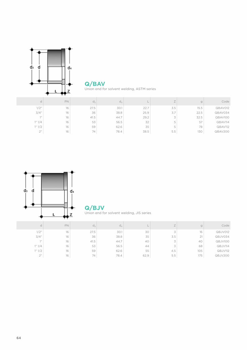
d PN d3 d4 L Z g Code
1/2” 16 27.5 30.1 30 3 16 QBJV012 3/4” 16 36 38.8 35 3.5 21 QBJV034
1” 16 41.5 44.7 40 3 40 QBJV100 1” 1/4 16 53 56.5 44 3 68 QBJV114 1” 1/2 16 59 62.6 55 4.5 105 QBJV112
2” 16 74 78.4 62.9 5.5 175 QBJV200
Q/BJVUnion end for solvent welding, JIS series
d PN d3 d4 L Z g Code
1/2” 16 27.5 30.1 22.7 3.5 15.5 QBAV012 3/4” 16 36 38.8 25.9 3.7 22.5 QBAV034
1” 16 41.5 44.7 29.2 3 32.5 QBAV100 1” 1/4 16 53 56.5 32 5 57 QBAV114 1” 1/2 16 59 62.6 35 5 78 QBAV112
2” 16 74 78.4 38.5 5.5 130 QBAV200
Q/BAVUnion end for solvent welding, ASTM series

65
R d3 d4 H L1 g Code
3/8” 22 24 21.5 13.5 38 QBFO0381/2” 27.5 30.1 22.5 16.5 60 QBFO0123/4” 36 38.8 25.5 18.5 116 QBFO034
1” 41.5 44.7 27.5 19.5 144 QBFO1001” 1/4 53 56.5 30.5 21.5 260 QBFO1141” 1/2 59 62.6 33.5 23 325 QBFO112
2” 74 78.4 38.5 27 578 QBFO200
Q/BFOUnion end in brass with female BSP thread
R d3 d4 H L1 g Code
3/8” 22 24 34.5 10.5 64 QBRO0381/2” 27.5 30.1 39 13.5 105 QBRO0123/4” 36 38.8 43.5 15 184 QBRO034
1” 41.5 44.7 48 17.5 251 QBRO1001” 1/4 53 56.5 53 19.5 437 QBRO1141” 1/2 59 62.6 56 19.5 545 QBRO112
2” 74 78.4 65.5 24 937 QBRO200
Q/BROUnion end in brass with male BSP thread
66
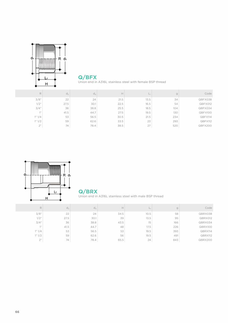
R d3 d4 H L1 g Code
3/8” 22 24 21.5 13.5 34 QBFX0381/2” 27.5 30.1 22.5 16.5 54 QBFX0123/4” 36 38.8 25.5 18.5 104 QBFX034
1” 41.5 44.7 27.5 19.5 130 QBFX1001” 1/4 53 56.5 30.5 21.5 234 QBFX1141” 1/2 59 62.6 33.5 23 293 QBFX112
2” 74 78.4 38.5 27 520 QBFX200
Q/BFXUnion end in A316L stainless steel with female BSP thread
R d3 d4 H L1 g Code
3/8” 22 24 34.5 10.5 58 QBRX0381/2” 27.5 30.1 39 13.5 95 QBRX0123/4” 36 38.8 43.5 15 166 QBRX034
1” 41.5 44.7 48 17.5 226 QBRX1001” 1/4 53 56.5 53 19.5 393 QBRX1141” 1/2 59 62.6 56 19.5 491 QBRX112
2” 74 78.4 65.5 24 843 QBRX200
Q/BRXUnion end in A316L stainless steel with male BSP thread
67
Union d C di T EPDM code FPM code
16 3062 15.54 2.62 OR3062E OR3062F20 4081 20.22 3.53 OR4081E OR4081F25 4112 28.17 3.53 OR4112E OR4112F32 4131 32.93 3.53 OR4131E OR4131F40 6162 40.65 5.34 OR6162E OR6162F50 6187 47 5.34 OR6187E OR6187F63 6237 59.69 5.34 OR6237E OR6237F75 6300 75.57 5.34 OR6300E OR6300F90 6362 91.45 5.34 OR6362E OR6362F110 6450 113.67 5.34 OR6450E OR6450F
O-RingO-Ring for union types BIV, BIFV, BFV, BLV, BIRV, BIFOV, BIROV, BIFXV, BIRXV
d x R PN A H K K1 L L1 L2 P g Code
25 x 1” 16 58 60 46 46 26 19 16 2 58 LIV02510032 x 1” 1/4 16 62 66 55 50 28 22 18 2 90 LIV032114
LIVTank connector with solvent weld spigot d, threaded joint R with tightening nut and flat gasket in EPDM
68
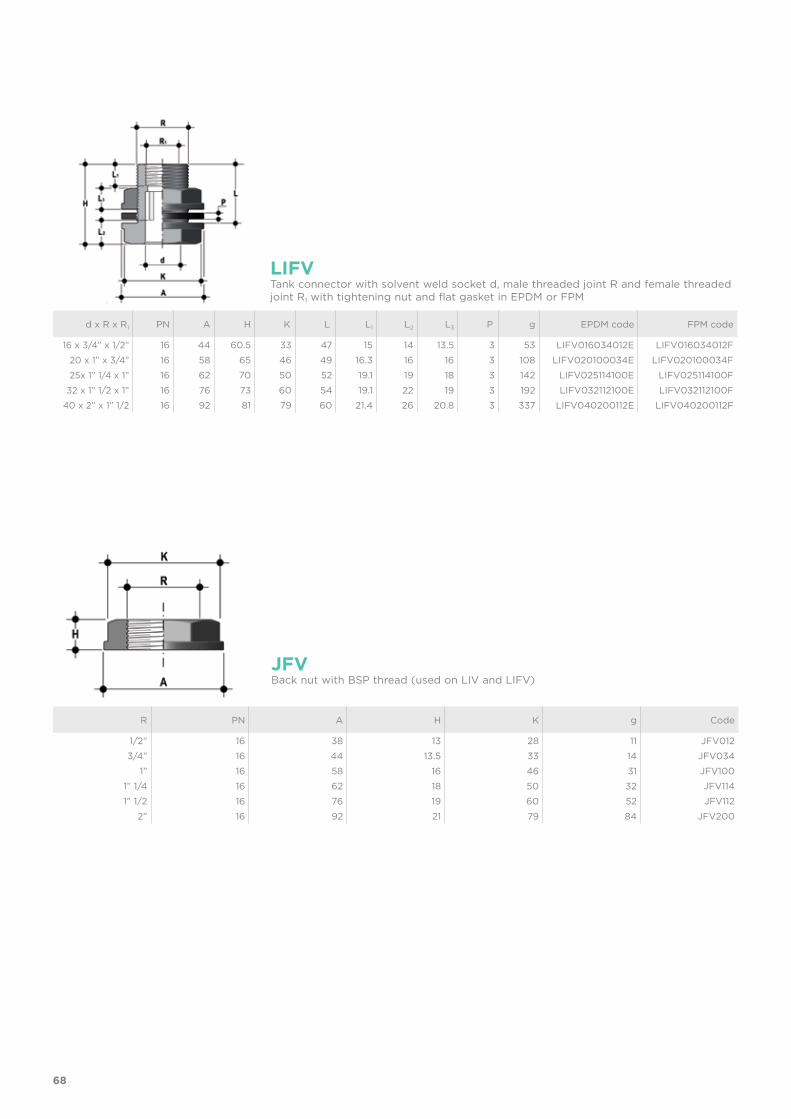
R PN A H K g Code
1/2” 16 38 13 28 11 JFV0123/4” 16 44 13.5 33 14 JFV034
1” 16 58 16 46 31 JFV1001” 1/4 16 62 18 50 32 JFV1141” 1/2 16 76 19 60 52 JFV112
2” 16 92 21 79 84 JFV200
JFVBack nut with BSP thread (used on LIV and LIFV)
d x R x R1 PN A H K L L1 L2 L3 P g EPDM code FPM code
16 x 3/4” x 1/2” 16 44 60.5 33 47 15 14 13.5 3 53 LIFV016034012E LIFV016034012F20 x 1” x 3/4” 16 58 65 46 49 16.3 16 16 3 108 LIFV020100034E LIFV020100034F25x 1” 1/4 x 1” 16 62 70 50 52 19.1 19 18 3 142 LIFV025114100E LIFV025114100F
32 x 1” 1/2 x 1” 16 76 73 60 54 19.1 22 19 3 192 LIFV032112100E LIFV032112100F40 x 2” x 1” 1/2 16 92 81 79 60 21.4 26 20.8 3 337 LIFV040200112E LIFV040200112F
LIFVTank connector with solvent weld socket d, male threaded joint R and female threaded joint R1 with tightening nut and flat gasket in EPDM or FPM

69


BSP FITTINGSPVC-U
Threaded fittings
72
Technical specificationsSize range R 3/8” ÷ 4”Nominal pressure PN 16 with water at 20 °CTemperature range 0 °C ÷ 60 °CCoupling standards Thread: ISO 228-1, DIN 2999, ISO 7, BS 21,
ASTM D 2464, JIS B0203Flanged couplings: DIN 2501, EN 1092-1
Reference standards Construction criteria: EN ISO 1452, EN ISO 15493Test methods and requirements: EN ISO 1452, EN ISO 15493
Valve material PVC-USeal material EPDM, FPM
FITTINGS
Series of fittings for pipes conveying fluids under pressure with threaded joints.
THREADED FITTINGS
BSP

73
REGRESSION CURVE FOR PVC-U FITTINGS
Ho
op
str
ess
Time to failure
bar0.1 1 10 102 103 104 105 106 h
20
25
304050
15
10
0.5
1
1.5
2
2.533.545
6789
20 °C30 °C40 °C
50 °C
60 °C
1 5 10 25 50 100Years
TECHNICAL DATA
-40 -20 0 20 40 60 80 100 120 140 °C
16
14
12
10
8
6
4
2
0
Wo
rkin
g p
ress
ure
Working temperature
barPRESSURE VARIATION ACCORDING TO TEMPERATURE
For water and non-hazardous fluids for which the material is classified as CHEMICALLY RESISTANT (life expectancy 25 years). In other cases, a reduction of the nominal pressure PN is required.
Regression coefficients according to EN ISO 1452 and EN ISO 15493 for MRS (minimum required strength) values = 25 N/mm2 (MPa) (classification PVC-U 250)

74
The information in this leaflet is provided in good faith. FIP will not be held liable for technical data not originating directly from recognised international standards. The company reserves the right to carry out any modifications. Products must be installed and maintained by qualified personnel.
SAFETY FACTORS
The table reports the safety factors for each pressure class as a function of time.
Nominal pressure PN must be understood as being the standard pressure used for calculating and selecting the required fittings. In order to be able to comply with the safety factors, the maximum continuous working pressure at 20° C when conveying water must be the same as the nominal pressure values.Unless otherwise specified, the nominal pressures are as follows:• solvent weld fittings
from d 12 to d 225 PN 16 from d 250 to d 315 PN 10
• adaptor fittings from d 16 to d 110 PN 16
• threaded fittings from R 3/8” to R 4” up to PN 16.
Some of the fittings in the series are sold as PN16 with a reduced safety factor compared to that specified by ISO standards.
1h 1000h 50 years T
10 6.72 5.12 4
16 4.2 3.2 2.5
16* 3.3 2.5 2*with reduced safety factor
Pe (bar)
75
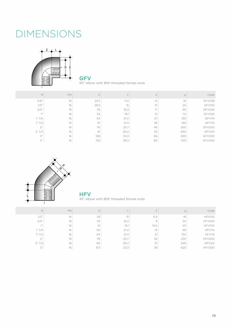
R PN E L Z g Code
3/8” 16 23.5 11.4 13 16 GFV0381/2” 16 28.5 15 13 24 GFV0123/4” 16 35 16.3 17 40 GFV034
1” 16 43 19.1 21 72 GFV1001” 1/4 16 54 21.4 27 130 GFV1141” 1/2 16 61 21.4 36 185 GFV112
2” 16 76 25.7 46 350 GFV2002” 1/2 16 91 30.2 55 450 GFV212
3” 16 108 33.3 66 835 GFV3004” 16 130 39.3 80 1135 GFV400
GFV90° elbow with BSP threaded female ends
R PN E L Z g Code
1/2” 16 28 15 6.5 18 HFV0123/4” 16 33 16.3 8 24 HFV034
1” 16 41 19.1 10.5 45 HFV1001” 1/4 16 50 21.4 15 68 HFV1141” 1/2 16 64 21.4 21 154 HFV112
2” 16 76 25.7 26 255 HFV2002” 1/2 16 90 30.2 31 345 HFV212
3” 16 107 33.3 39 625 HFV300
HFV45° elbow with BSP threaded female ends
DIMENSIONS
76
R PN E K L Z g Code
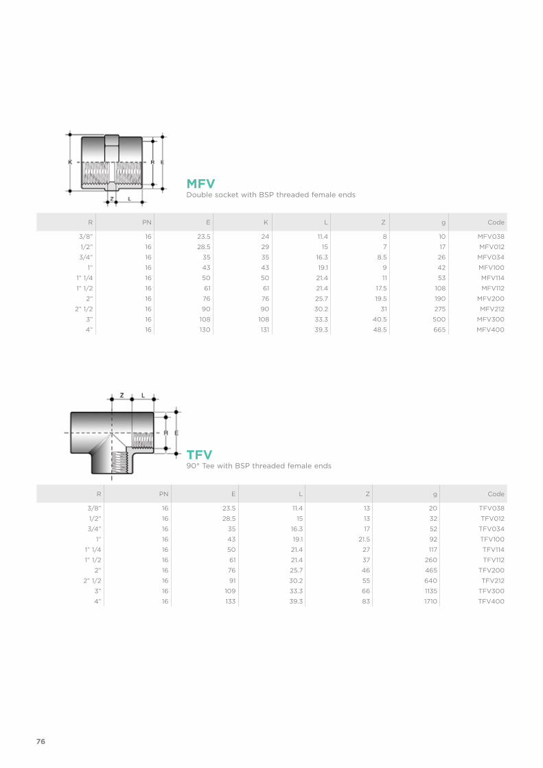
3/8” 16 23.5 24 11.4 8 10 MFV0381/2” 16 28.5 29 15 7 17 MFV0123/4” 16 35 35 16.3 8.5 26 MFV034
1” 16 43 43 19.1 9 42 MFV1001” 1/4 16 50 50 21.4 11 53 MFV1141” 1/2 16 61 61 21.4 17.5 108 MFV112
2” 16 76 76 25.7 19.5 190 MFV2002” 1/2 16 90 90 30.2 31 275 MFV212
3” 16 108 108 33.3 40.5 500 MFV3004” 16 130 131 39.3 48.5 665 MFV400
MFVDouble socket with BSP threaded female ends
TFV90° Tee with BSP threaded female ends
R PN E L Z g Code
3/8” 16 23.5 11.4 13 20 TFV0381/2” 16 28.5 15 13 32 TFV0123/4” 16 35 16.3 17 52 TFV034
1” 16 43 19.1 21.5 92 TFV1001” 1/4 16 50 21.4 27 117 TFV1141” 1/2 16 61 21.4 37 260 TFV112
2” 16 76 25.7 46 465 TFV2002” 1/2 16 91 30.2 55 640 TFV212
3” 16 109 33.3 66 1135 TFV3004” 16 133 39.3 83 1710 TFV400
77
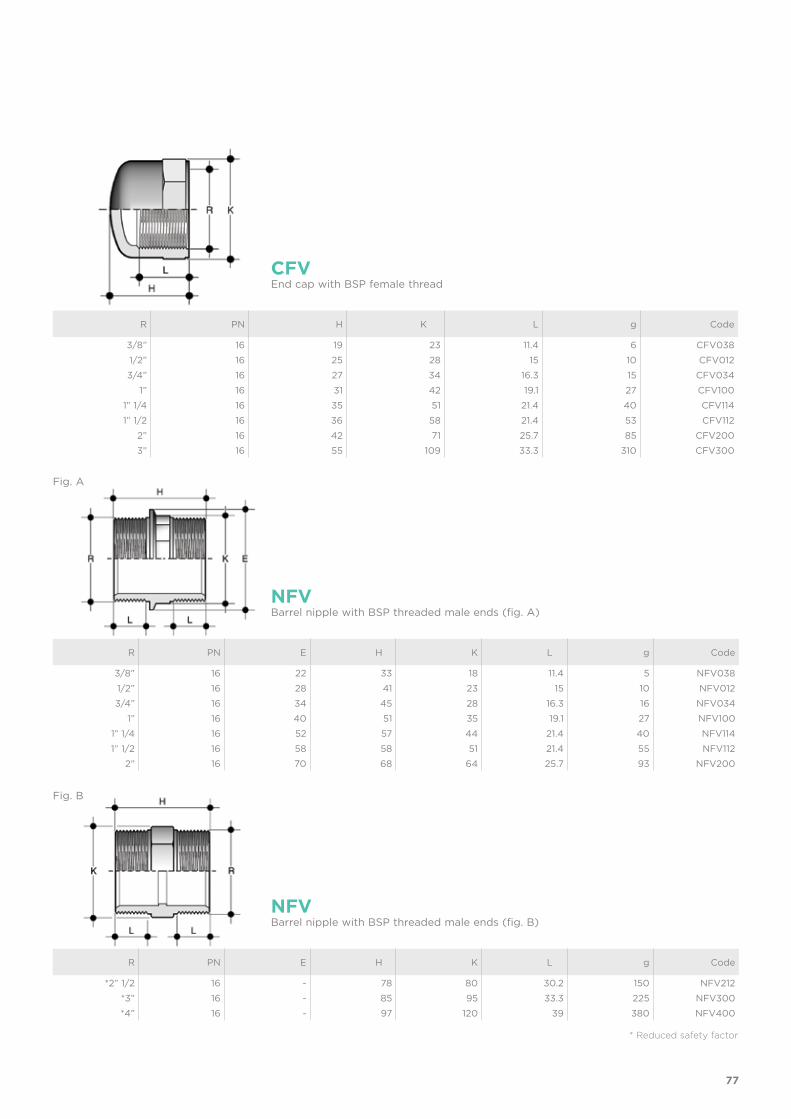
R PN E H K L g Code
3/8” 16 22 33 18 11.4 5 NFV0381/2” 16 28 41 23 15 10 NFV0123/4” 16 34 45 28 16.3 16 NFV034
1” 16 40 51 35 19.1 27 NFV1001” 1/4 16 52 57 44 21.4 40 NFV1141” 1/2 16 58 58 51 21.4 55 NFV112
2” 16 70 68 64 25.7 93 NFV200
R PN E H K L g Code
*2” 1/2 16 - 78 80 30.2 150 NFV212*3” 16 - 85 95 33.3 225 NFV300*4” 16 - 97 120 39 380 NFV400
NFV
NFV
Barrel nipple with BSP threaded male ends (fig. A)
Barrel nipple with BSP threaded male ends (fig. B)
R PN H K L g Code
3/8” 16 19 23 11.4 6 CFV0381/2” 16 25 28 15 10 CFV0123/4” 16 27 34 16.3 15 CFV034
1” 16 31 42 19.1 27 CFV1001” 1/4 16 35 51 21.4 40 CFV114
1” 1/2 16 36 58 21.4 53 CFV1122” 16 42 71 25.7 85 CFV2003” 16 55 109 33.3 310 CFV300
CFVEnd cap with BSP female thread
* Reduced safety factor
Fig. A
Fig. B
78
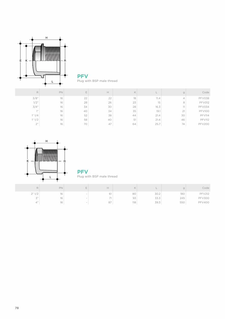
R PN E H K L g Code
3/8” 16 22 22 18 11.4 4 PFV0381/2” 16 28 26 23 15 8 PFV0123/4” 16 34 30 28 16.3 11 PFV034
1” 16 40 34 35 19.1 21 PFV1001” 1/4 16 52 38 44 21.4 30 PFV114
1” 1/2 16 58 40 51 21.4 46 PFV1122” 16 70 47 64 25.7 74 PFV200
R PN E H K L g Code
2” 1/2 16 - 61 80 30.2 180 PFV2123” 16 - 71 93 33.3 245 PFV3004” 16 - 87 118 39.3 550 PFV400
PFV
PFV
Plug with BSP male thread
Plug with BSP male thread
79
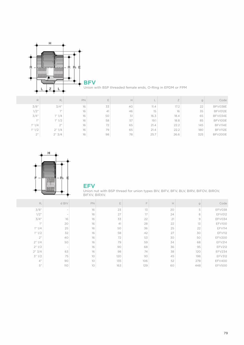
BFVUnion with BSP threaded female ends, O-Ring in EPDM or FPM
R R1 PN E H L Z g Code
3/8” 3/4” 16 33 40 11.4 17.2 22 BFV038E1/2” 1” 16 41 46 15 16 35 BFV012E3/4” 1” 1/4 16 50 51 16.3 18.4 65 BFV034E
1” 1” 1/2 16 58 57 19.1 18.8 85 BFV100E1” 1/4 2” 16 72 65 21.4 22.2 145 BFV114E1” 1/2 2” 1/4 16 79 65 21.4 22.2 180 BFV112E
2” 2” 3/4 16 98 78 25.7 26.6 325 BFV200E
R1 d BIV PN E F H g Code
3/8” - 16 23 13 20 5 EFV0381/2” - 16 27 17 24 8 EFV0123/4” 16 16 33 22 21 9 EFV034
1” 20 16 41 28 22 13 EFV1001” 1/4 25 16 50 36 25 22 EFV1141” 1/2 32 16 58 42 27 30 EFV112
2” 40 16 72 53 30 50 EFV2002” 1/4 50 16 79 59 34 68 EFV2142” 1/2 - 16 90 68 36 95 EFV2122” 3/4 63 16 98 74 38 120 EFV2343” 1/2 75 10 120 93 45 198 EFV312
4” 90 10 135 106 52 278 EFV4005” 110 10 163 129 60 448 EFV500
EFVUnion nut with BSP thread for union types BIV, BIFV, BFV, BLV, BIRV, BIFOV, BIROV, BIFXV, BIRXV.
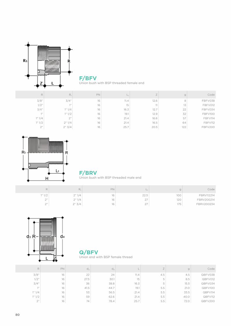
80
R PN d3 d4 L Z g Code
3/8” 16 22 24 11.4 4.5 4.5 QBFV0381/2” 16 27.5 30.1 15 5 8.5 QBFV0123/4” 16 36 38.8 16.3 5 15.5 QBFV034
1” 16 41.5 44.7 19.1 5.5 21.0 QBFV1001” 1/4 16 53 56.5 21.4 5.5 33.5 QBFV1141” 1/2 16 59 62.6 21.4 5.5 40.0 QBFV112
2” 16 74 78.4 25.7 5.5 72.0 QBFV200
Q/BFVUnion end with BSP female thread
R R1 PN L1 g Code
1” 1/2 2” 1/4 16 22.5 100 FBRV1122142” 2” 1/4 16 27 120 FBRV2002142” 2” 3/4 16 27 175 FBRV200234
F/BRVUnion bush with BSP threaded male end
R R1 PN L1 Z g Code
3/8” 3/4” 16 11.4 12.6 8 FBFV0381/2” 1” 16 15 11 13 FBFV0123/4” 1” 1/4 16 16.3 12.7 22 FBFV034
1” 1” 1/2 16 19.1 12.9 32 FBFV1001” 1/4 2” 16 21.4 16.6 57 FBFV1141” 1/2 2” 1/4 16 21.4 16.5 64 FBFV112
2” 2” 3/4 16 25.7 20.5 122 FBFV200
F/BFVUnion bush with BSP threaded female end
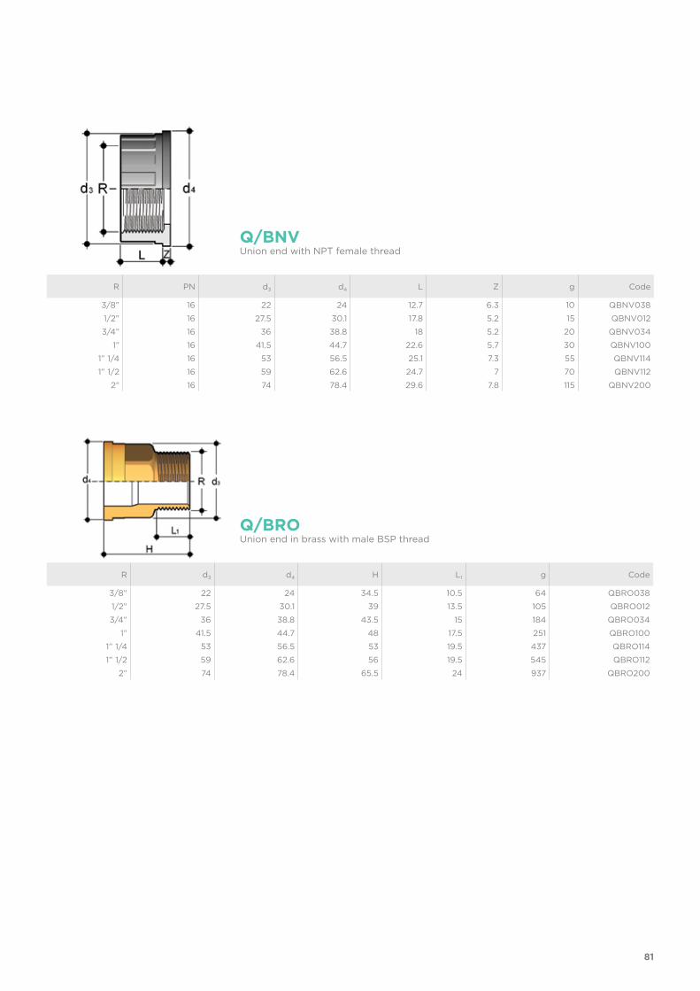
81
R PN d3 d4 L Z g Code
3/8” 16 22 24 12.7 6.3 10 QBNV0381/2” 16 27.5 30.1 17.8 5.2 15 QBNV0123/4” 16 36 38.8 18 5.2 20 QBNV034
1” 16 41.5 44.7 22.6 5.7 30 QBNV1001” 1/4 16 53 56.5 25.1 7.3 55 QBNV1141” 1/2 16 59 62.6 24.7 7 70 QBNV112
2” 16 74 78.4 29.6 7.8 115 QBNV200
Q/BNVUnion end with NPT female thread
R d3 d4 H L1 g Code
3/8” 22 24 34.5 10.5 64 QBRO0381/2” 27.5 30.1 39 13.5 105 QBRO0123/4” 36 38.8 43.5 15 184 QBRO034
1” 41.5 44.7 48 17.5 251 QBRO1001” 1/4 53 56.5 53 19.5 437 QBRO1141” 1/2 59 62.6 56 19.5 545 QBRO112
2” 74 78.4 65.5 24 937 QBRO200
Q/BROUnion end in brass with male BSP thread
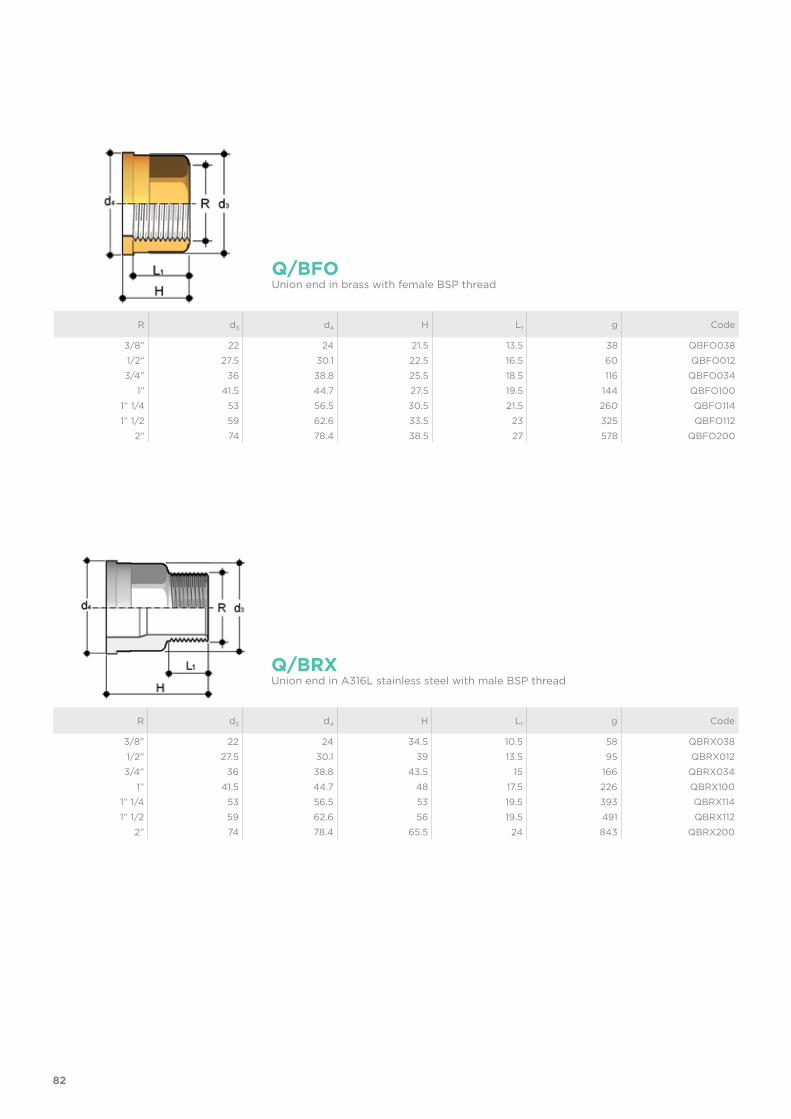
82
R d3 d4 H L1 g Code
3/8” 22 24 34.5 10.5 58 QBRX0381/2” 27.5 30.1 39 13.5 95 QBRX0123/4” 36 38.8 43.5 15 166 QBRX034
1” 41.5 44.7 48 17.5 226 QBRX1001” 1/4 53 56.5 53 19.5 393 QBRX1141” 1/2 59 62.6 56 19.5 491 QBRX112
2” 74 78.4 65.5 24 843 QBRX200
Q/BRXUnion end in A316L stainless steel with male BSP thread
R d3 d4 H L1 g Code
3/8” 22 24 21.5 13.5 38 QBFO0381/2” 27.5 30.1 22.5 16.5 60 QBFO0123/4” 36 38.8 25.5 18.5 116 QBFO034
1” 41.5 44.7 27.5 19.5 144 QBFO1001” 1/4 53 56.5 30.5 21.5 260 QBFO1141” 1/2 59 62.6 33.5 23 325 QBFO112
2” 74 78.4 38.5 27 578 QBFO200
Q/BFOUnion end in brass with female BSP thread
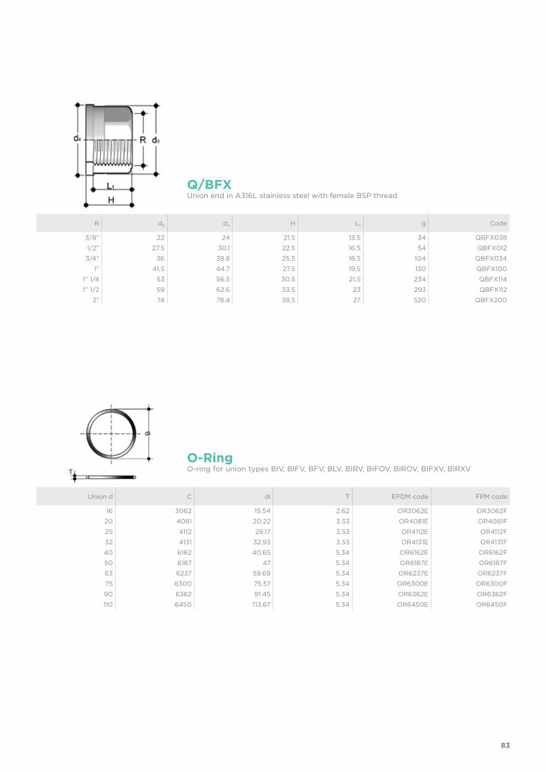
83
Union d C di T EPDM code FPM code
16 3062 15.54 2.62 OR3062E OR3062F20 4081 20.22 3.53 OR4081E OR4081F25 4112 28.17 3.53 OR4112E OR4112F32 4131 32.93 3.53 OR4131E OR4131F40 6162 40.65 5.34 OR6162E OR6162F50 6187 47 5.34 OR6187E OR6187F63 6237 59.69 5.34 OR6237E OR6237F75 6300 75.57 5.34 OR6300E OR6300F90 6362 91.45 5.34 OR6362E OR6362F110 6450 113.67 5.34 OR6450E OR6450F
O-RingO-ring for union types BIV, BIFV, BFV, BLV, BIRV, BIFOV, BIROV, BIFXV, BIRXV
R d3 d4 H L1 g Code
3/8” 22 24 21.5 13.5 34 QBFX0381/2” 27.5 30.1 22.5 16.5 54 QBFX0123/4” 36 38.8 25.5 18.5 104 QBFX034
1” 41.5 44.7 27.5 19.5 130 QBFX1001” 1/4 53 56.5 30.5 21.5 234 QBFX1141” 1/2 59 62.6 33.5 23 293 QBFX112
2” 74 78.4 38.5 27 520 QBFX200
Q/BFXUnion end in A316L stainless steel with female BSP thread

84
R x R1 PN E H K L L1 g Code
1/2” x 3/8” 16 28 35 23 15 11.4 10 RFV0120383/4” x 3/8” 16 34 36 28 16.3 11.4 12 RFV0340383/4” x 1/2” 16 34 39 28 16.3 15 15 RFV034012
1” x 3/8” 16 40 41 35 19.1 11.4 20 RFV1000381” x 1/2” 16 40 44 35 19.1 15 24 RFV1000121” x 3/4” 16 40 46 35 19.1 16.3 25 RFV100034
1” 1/4 x 1/2” 16 52 48 44 21.4 15 37 RFV1140121” 1/4 x 3/4” 16 52 49 44 21.4 16.3 37 RFV114034
1” 1/4 x 1” 16 52 52 44 21.4 19.1 40 RFV1141001” 1/2 x 1/2” 16 58 52 51 21.4 15 46 RFV1120121” 1/2 x 3/4” 16 58 50 51 21.4 16.3 47 RFV112034
1” 1/2 x 1” 16 58 55 51 21.4 19.1 52 RFV1121001” 1/2 x 1” 1/4 16 58 57 51 21.4 21.4 54 RFV112114
2” x 3/4” 16 70 60 64 25.7 16.3 80 RFV2000342” x 1” 16 70 63 64 25.7 19.1 80 RFV200100
2” x 1” 1/4 16 70 65 64 25.7 21.4 85 RFV2001142” x 1” 1/2 16 70 65 64 25.7 21.4 102 RFV200112
RFVReducer with BSP threaded male end (R) and BSP threaded female end (R1 reduced) (fig. A)
R1 x R PN H K L L1 g Code
3/4” x 1/2” 16 43 30 15 16.3 16 NRFV0340121” x 3/4” 16 48 36 16.3 19.1 26 NRFV100034
1” 1/4 x 1” 16 54 46 19.1 21.4 46 NRFV1141001” 1/2 x 1” 1/4 16 57 50 21.4 21.4 60 NRFV112114
2” x 1” 1/2 16 62 65 21.4 25.7 88 NRFV2001122” 1/2 x 2” 16 73 80 25.7 30.2 140 NRFV2122003” x 2” 1/2 16 82 95 30.2 33.3 220 NRFV300212
4” x 3” 16 90 120 33.3 39.3 350 NRFV400300
NRFVReducing barrel nipple with BSP threaded male ends
Fig. A
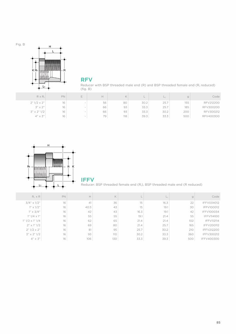
85
R x R1 PN E H K L L1 g Code
2” 1/2 x 2” 16 - 56 80 30.2 25.7 155 RFV2122003” x 2” 16 - 66 93 33.3 25.7 185 RFV300200
3” x 2” 1/2 16 - 66 93 33.3 30.2 200 RFV3002124” x 3” 16 - 79 118 39.3 33.3 500 RFV400300
RFVReducer with BSP threaded male end (R) and BSP threaded female end (R1 reduced) (fig. B)
R1 x R PN H K L L1 g Code
3/4” x 1/2” 16 41 36 15 16.3 22 IFFV034012 1” x 1/2” 16 40.5 43 15 19.1 30 IFFV1000121” x 3/4” 16 42 43 16.3 19.1 42 IFFV100034
1” 1/4 x 1” 16 55 55 19.1 21.4 55 IFFV1141001” 1/2 x 1” 1/4 16 62 65 21.4 21.4 102 IFFV112114
2” x 1” 1/2 16 69 80 21.4 25.7 165 IFFV2001122” 1/2 x 2” 16 81 95 25.7 30.2 210 IFFV2122003” x 2” 1/2 16 93 110 30.2 33.3 360 IFFV300212
4” x 3” 16 106 130 33.3 39.3 500 IFFV400300
IFFVReducer: BSP threaded female end (R1), BSP threaded male end (R reduced)
Fig. B
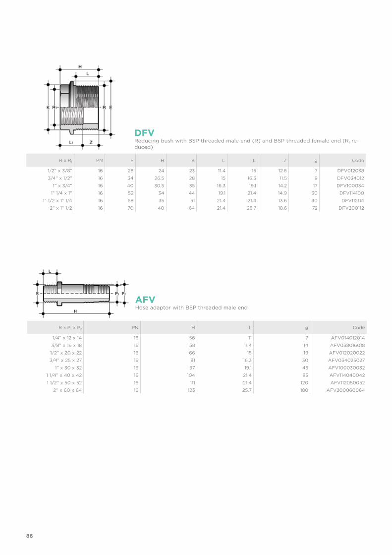
86
R x P1 x P2 PN H L g Code
1/4” x 12 x 14 16 56 11 7 AFV0140120143/8” x 16 x 18 16 58 11.4 14 AFV0380160181/2” x 20 x 22 16 66 15 19 AFV0120200223/4” x 25 x 27 16 81 16.3 30 AFV034025027
1” x 30 x 32 16 97 19.1 45 AFV1000300321 1/4” x 40 x 42 16 104 21.4 85 AFV1140400421 1/2” x 50 x 52 16 111 21.4 120 AFV112050052
2” x 60 x 64 16 123 25.7 180 AFV200060064
AFVHose adaptor with BSP threaded male end
DFVReducing bush with BSP threaded male end (R) and BSP threaded female end (R1 re-duced)
R x R1 PN E H K L L Z g Code
1/2” x 3/8” 16 28 24 23 11.4 15 12.6 7 DFV0120383/4” x 1/2” 16 34 26.5 28 15 16.3 11.5 9 DFV034012
1” x 3/4” 16 40 30.5 35 16.3 19.1 14.2 17 DFV1000341” 1/4 x 1” 16 52 34 44 19.1 21.4 14.9 30 DFV114100
1” 1/2 x 1” 1/4 16 58 35 51 21.4 21.4 13.6 30 DFV1121142” x 1” 1/2 16 70 40 64 21.4 25.7 18.6 72 DFV200112
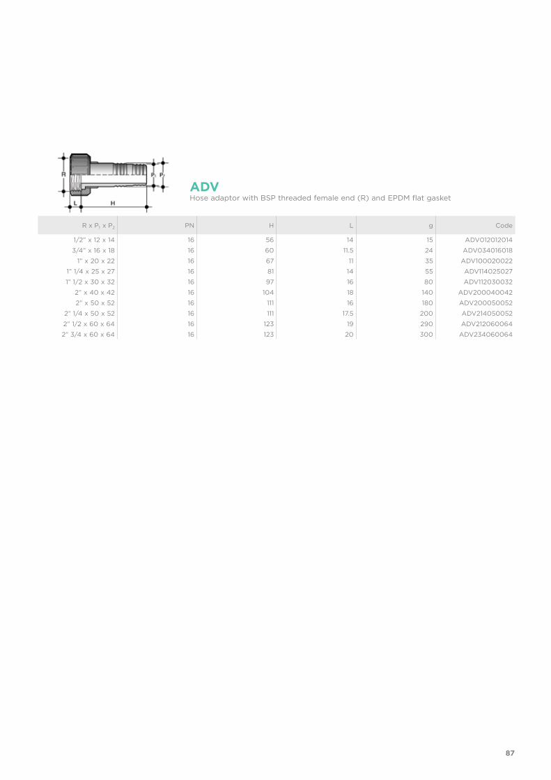
87
R x P1 x P2 PN H L g Code
1/2” x 12 x 14 16 56 14 15 ADV0120120143/4” x 16 x 18 16 60 11.5 24 ADV034016018
1” x 20 x 22 16 67 11 35 ADV1000200221” 1/4 x 25 x 27 16 81 14 55 ADV1140250271” 1/2 x 30 x 32 16 97 16 80 ADV112030032
2” x 40 x 42 16 104 18 140 ADV2000400422” x 50 x 52 16 111 16 180 ADV200050052
2” 1/4 x 50 x 52 16 111 17.5 200 ADV2140500522” 1/2 x 60 x 64 16 123 19 290 ADV2120600642” 3/4 x 60 x 64 16 123 20 300 ADV234060064
ADVHose adaptor with BSP threaded female end (R) and EPDM flat gasket

BS FITTINGSPVC-U
Solvent weld and threaded fittings according to British Standard
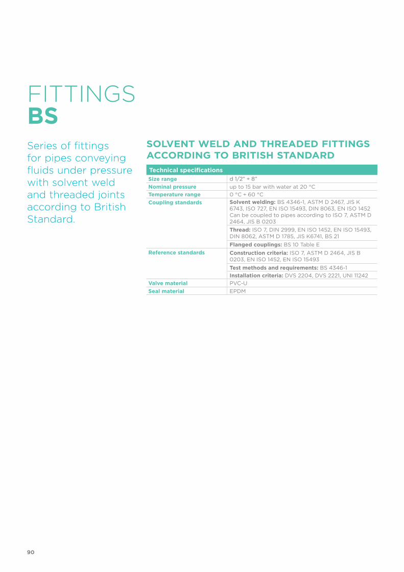
90
Technical specificationsSize range d 1/2” ÷ 8”Nominal pressure up to 15 bar with water at 20 °CTemperature range 0 °C ÷ 60 °CCoupling standards Solvent welding: BS 4346-1, ASTM D 2467, JIS K
6743, ISO 727, EN ISO 15493, DIN 8063, EN ISO 1452 Can be coupled to pipes according to ISO 7, ASTM D 2464, JIS B 0203Thread: ISO 7, DIN 2999, EN ISO 1452, EN ISO 15493, DIN 8062, ASTM D 1785, JIS K6741, BS 21Flanged couplings: BS 10 Table E
Reference standards Construction criteria: ISO 7, ASTM D 2464, JIS B 0203, EN ISO 1452, EN ISO 15493Test methods and requirements: BS 4346-1Installation criteria: DVS 2204, DVS 2221, UNI 11242
Valve material PVC-USeal material EPDM
FITTINGS
Series of fittings for pipes conveying fluids under pressure with solvent weld and threaded joints according to British Standard.
SOLVENT WELD AND THREADED FITTINGS ACCORDING TO BRITISH STANDARD
BS
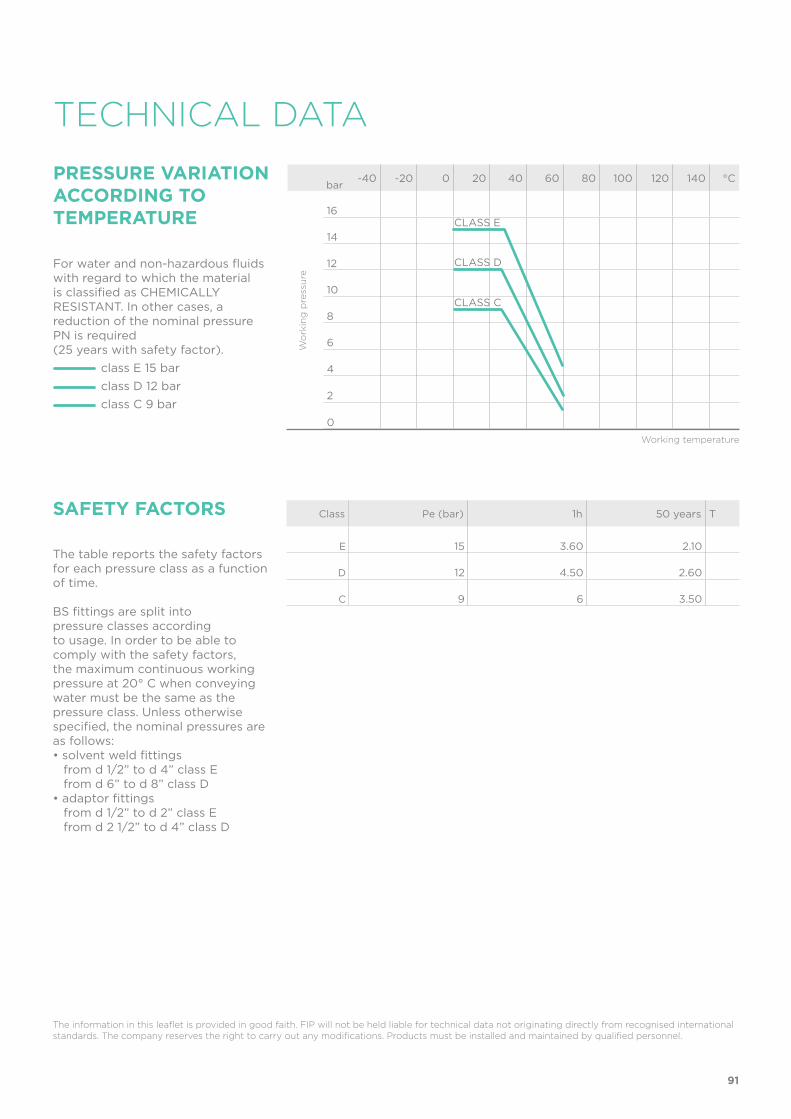
91
TECHNICAL DATA
-40 -20 0 20 40 60 80 100 120 140 °C
16
14
12
10
8
6
4
2
0
Wo
rkin
g p
ress
ure
Working temperature
barPRESSURE VARIATION ACCORDING TO TEMPERATURE
For water and non-hazardous fluids with regard to which the material is classified as CHEMICALLY RESISTANT. In other cases, a reduction of the nominal pressure PN is required (25 years with safety factor). class E 15 bar class D 12 bar class C 9 bar
CLASS E
CLASS D
CLASS C
SAFETY FACTORS
The table reports the safety factors for each pressure class as a function of time.
BS fittings are split intopressure classes accordingto usage. In order to be able to comply with the safety factors, the maximum continuous working pressure at 20° C when conveying water must be the same as the pressure class. Unless otherwise specified, the nominal pressures are as follows:• solvent weld fittings from d 1/2” to d 4” class E from d 6” to d 8” class D• adaptor fittings from d 1/2” to d 2” class E from d 2 1/2” to d 4” class D
Class Pe (bar) 1h 50 years T
E 15 3.60 2.10
D 12 4.50 2.60
C 9 6 3.50
The information in this leaflet is provided in good faith. FIP will not be held liable for technical data not originating directly from recognised international standards. The company reserves the right to carry out any modifications. Products must be installed and maintained by qualified personnel.
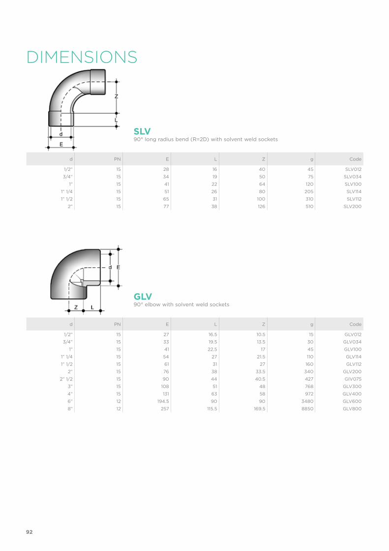
92
SLV90° long radius bend (R=2D) with solvent weld sockets
d PN E L Z g Code
1/2” 15 28 16 40 45 SLV0123/4” 15 34 19 50 75 SLV034
1” 15 41 22 64 120 SLV1001” 1/4 15 51 26 80 205 SLV1141” 1/2 15 65 31 100 310 SLV112
2” 15 77 38 126 510 SLV200
d PN E L Z g Code
1/2” 15 27 16.5 10.5 15 GLV0123/4” 15 33 19.5 13.5 30 GLV034
1” 15 41 22.5 17 45 GLV1001” 1/4 15 54 27 21.5 110 GLV1141” 1/2 15 61 31 27 160 GLV112
2” 15 76 38 33.5 340 GLV2002” 1/2 15 90 44 40.5 427 GIV075
3” 15 108 51 48 768 GLV3004” 15 131 63 58 972 GLV4006” 12 194.5 90 90 3480 GLV6008” 12 257 115.5 169.5 8850 GLV800
GLV90° elbow with solvent weld sockets
DIMENSIONS

93
d PN E L Z g Code
1/2” 15 27 16.5 2 13 MLV0123/4” 15 33 19.5 2 15 MLV034
1” 15 41 22.5 2 36 MLV1001” 1/4 15 50 26 3 58 MLV1141” 1/2 15 61 31 3 118 MLV112
2” 15 76 38 3 206 MLV2002” 1/2 15 90 44 4 250 MIV075
3” 15 108 50.5 5.5 420 MLV3004” 15 131 63 5 680 MLV4006” 12 194.5 90 10 1800 MLV6008” 12 257 115.5 12 4950 MLV800
MLVSolvent weld double socket
d PN E L Z g Code
1/2” 15 27 16.5 5 13 HLV0123/4” 15 33 19.5 5.5 20 HLV034
1” 15 41 22.5 7 45 HLV1001” 1/4 15 50 26 10.5 85 HLV1141” 1/2 15 61 31 11.5 155 HLV112
2” 15 76 38 14 291 HLV2002” 1/2 15 90 44 17 315 HIV075
3” 15 107.5 51 21.5 565 HLV3004” 15 131 61 26 740 HLV400
HLV45° elbow with solvent weld sockets
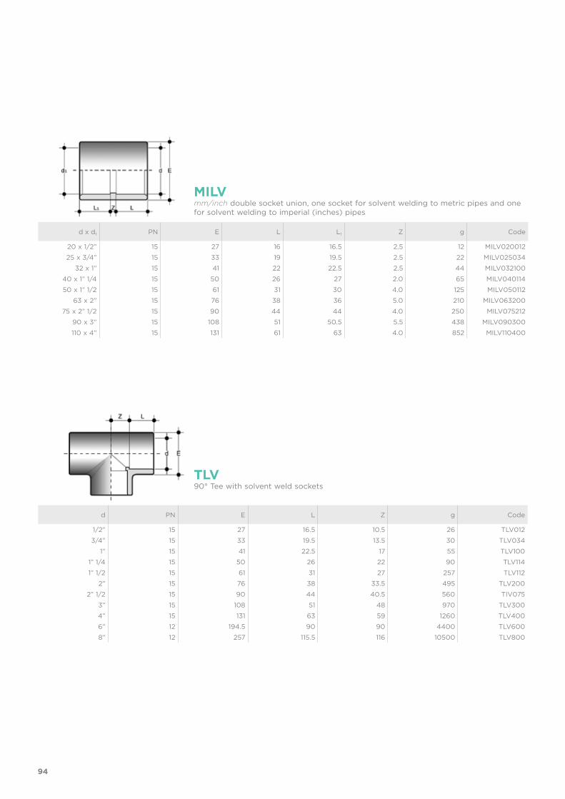
94
d x d1 PN E L L1 Z g Code
20 x 1/2” 15 27 16 16.5 2.5 12 MILV02001225 x 3/4” 15 33 19 19.5 2.5 22 MILV025034
32 x 1” 15 41 22 22.5 2.5 44 MILV03210040 x 1” 1/4 15 50 26 27 2.0 65 MILV04011450 x 1” 1/2 15 61 31 30 4.0 125 MILV050112
63 x 2” 15 76 38 36 5.0 210 MILV06320075 x 2” 1/2 15 90 44 44 4.0 250 MILV075212
90 x 3” 15 108 51 50.5 5.5 438 MILV090300110 x 4” 15 131 61 63 4.0 852 MILV110400
MILVmm/inch double socket union, one socket for solvent welding to metric pipes and one for solvent welding to imperial (inches) pipes
d PN E L Z g Code
1/2” 15 27 16.5 10.5 26 TLV0123/4” 15 33 19.5 13.5 30 TLV034
1” 15 41 22.5 17 55 TLV1001” 1/4 15 50 26 22 90 TLV1141” 1/2 15 61 31 27 257 TLV112
2” 15 76 38 33.5 495 TLV2002” 1/2 15 90 44 40.5 560 TIV075
3” 15 108 51 48 970 TLV3004” 15 131 63 59 1260 TLV4006” 12 194.5 90 90 4400 TLV6008” 12 257 115.5 116 10500 TLV800
TLV90° Tee with solvent weld sockets
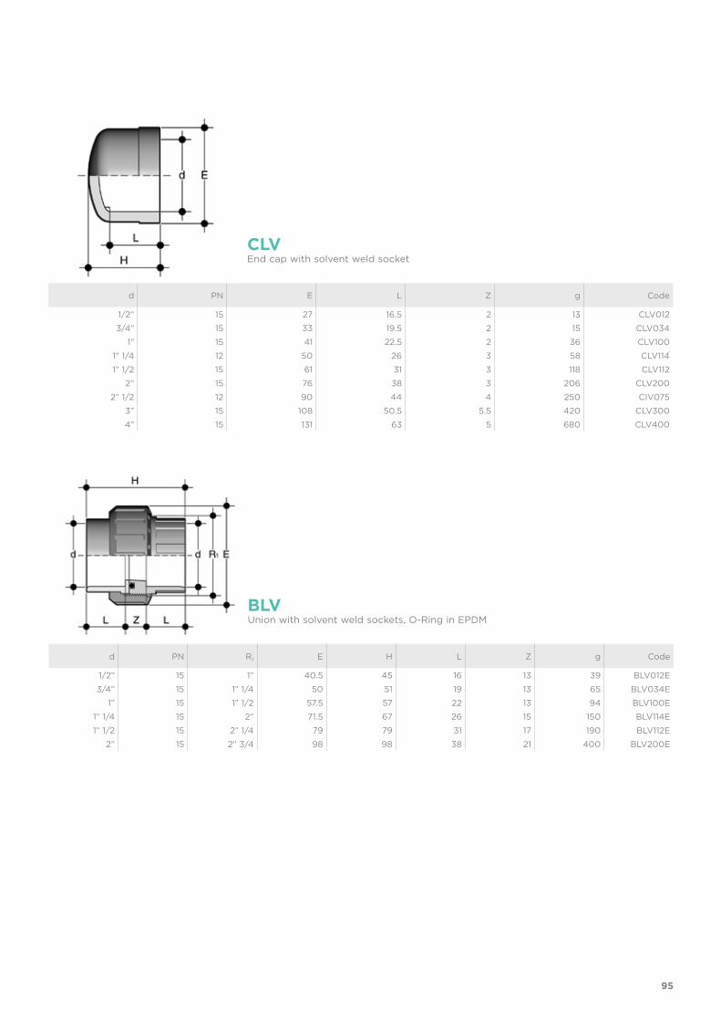
95
d PN E L Z g Code
1/2” 15 27 16.5 2 13 CLV0123/4” 15 33 19.5 2 15 CLV034
1” 15 41 22.5 2 36 CLV1001” 1/4 12 50 26 3 58 CLV1141” 1/2 15 61 31 3 118 CLV112
2” 15 76 38 3 206 CLV2002” 1/2 12 90 44 4 250 CIV075
3” 15 108 50.5 5.5 420 CLV3004” 15 131 63 5 680 CLV400
CLVEnd cap with solvent weld socket
d PN R1 E H L Z g Code
1/2” 15 1” 40.5 45 16 13 39 BLV012E3/4” 15 1” 1/4 50 51 19 13 65 BLV034E
1” 15 1” 1/2 57.5 57 22 13 94 BLV100E1” 1/4 15 2” 71.5 67 26 15 150 BLV114E1” 1/2 15 2” 1/4 79 79 31 17 190 BLV112E
2” 15 2” 3/4 98 98 38 21 400 BLV200E
BLVUnion with solvent weld sockets, O-Ring in EPDM
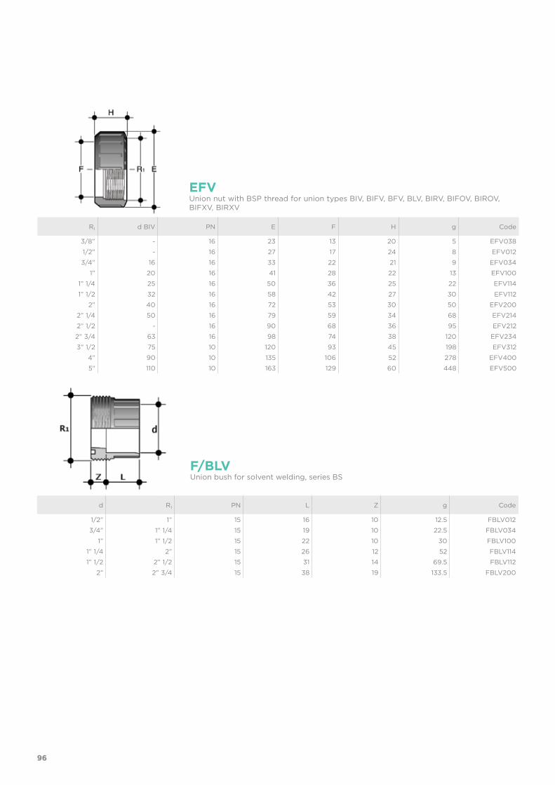
96
R1 d BIV PN E F H g Code
3/8” - 16 23 13 20 5 EFV0381/2” - 16 27 17 24 8 EFV0123/4” 16 16 33 22 21 9 EFV034
1” 20 16 41 28 22 13 EFV1001” 1/4 25 16 50 36 25 22 EFV1141” 1/2 32 16 58 42 27 30 EFV112
2” 40 16 72 53 30 50 EFV2002” 1/4 50 16 79 59 34 68 EFV2142” 1/2 - 16 90 68 36 95 EFV2122” 3/4 63 16 98 74 38 120 EFV2343” 1/2 75 10 120 93 45 198 EFV312
4” 90 10 135 106 52 278 EFV4005” 110 10 163 129 60 448 EFV500
EFVUnion nut with BSP thread for union types BIV, BIFV, BFV, BLV, BIRV, BIFOV, BIROV, BIFXV, BIRXV
d R1 PN L Z g Code
1/2” 1” 15 16 10 12.5 FBLV0123/4” 1” 1/4 15 19 10 22.5 FBLV034
1” 1” 1/2 15 22 10 30 FBLV1001” 1/4 2” 15 26 12 52 FBLV1141” 1/2 2” 1/2 15 31 14 69.5 FBLV112
2” 2” 3/4 15 38 19 133.5 FBLV200
F/BLVUnion bush for solvent welding, series BS
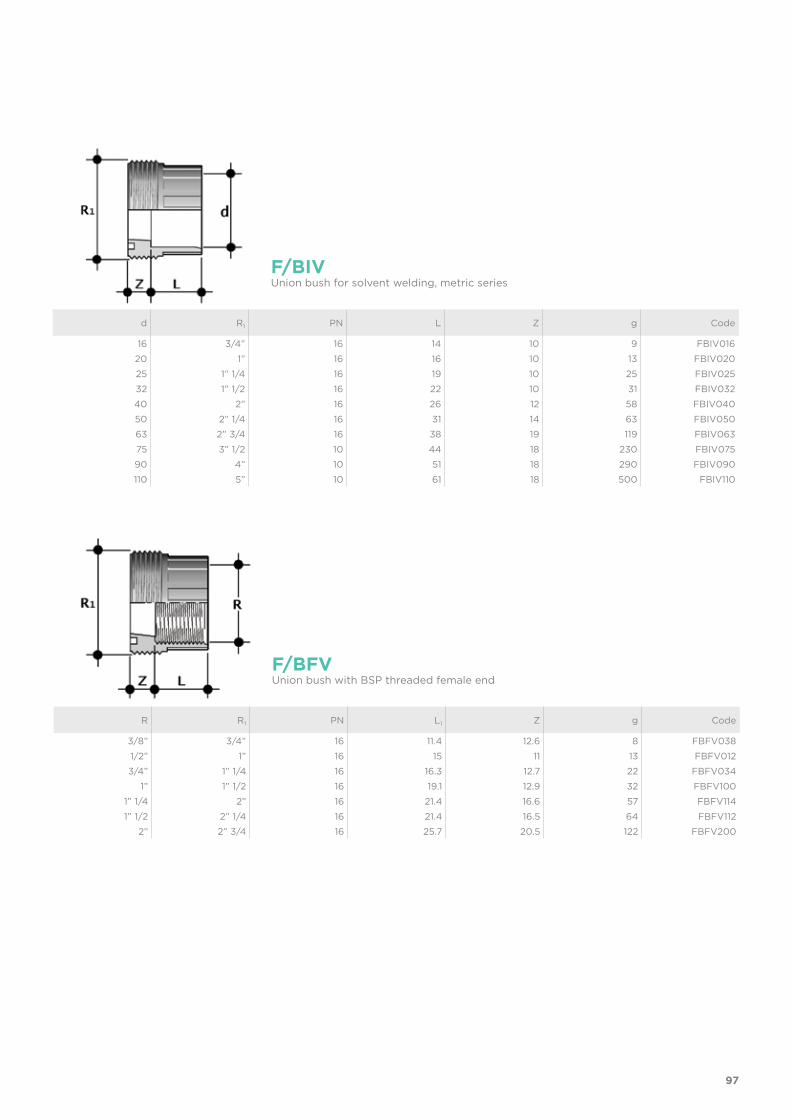
97
d R1 PN L Z g Code
16 3/4” 16 14 10 9 FBIV01620 1” 16 16 10 13 FBIV02025 1” 1/4 16 19 10 25 FBIV02532 1” 1/2 16 22 10 31 FBIV03240 2” 16 26 12 58 FBIV04050 2” 1/4 16 31 14 63 FBIV05063 2” 3/4 16 38 19 119 FBIV06375 3” 1/2 10 44 18 230 FBIV07590 4” 10 51 18 290 FBIV090110 5” 10 61 18 500 FBIV110
F/BIVUnion bush for solvent welding, metric series
R R1 PN L1 Z g Code
3/8” 3/4” 16 11.4 12.6 8 FBFV0381/2” 1” 16 15 11 13 FBFV0123/4” 1” 1/4 16 16.3 12.7 22 FBFV034
1” 1” 1/2 16 19.1 12.9 32 FBFV1001” 1/4 2” 16 21.4 16.6 57 FBFV1141” 1/2 2” 1/4 16 21.4 16.5 64 FBFV112
2” 2” 3/4 16 25.7 20.5 122 FBFV200
F/BFVUnion bush with BSP threaded female end
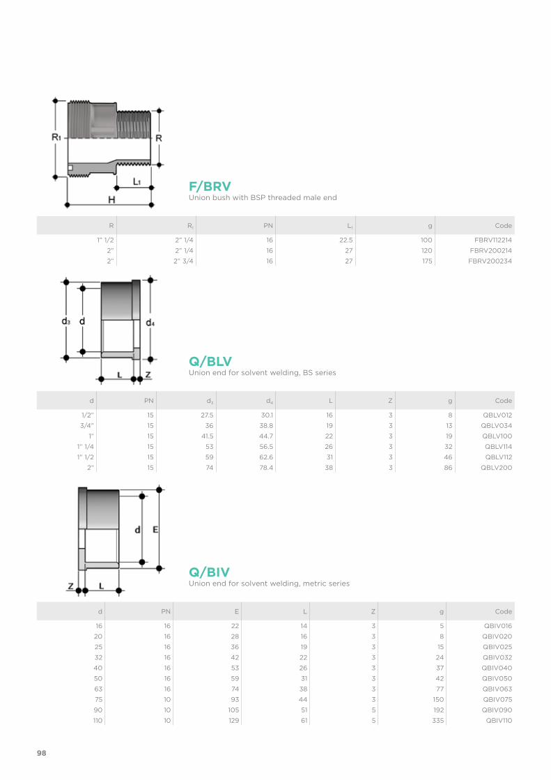
98
d PN E L Z g Code
16 16 22 14 3 5 QBIV01620 16 28 16 3 8 QBIV02025 16 36 19 3 15 QBIV02532 16 42 22 3 24 QBIV03240 16 53 26 3 37 QBIV04050 16 59 31 3 42 QBIV05063 16 74 38 3 77 QBIV06375 10 93 44 3 150 QBIV07590 10 105 51 5 192 QBIV090110 10 129 61 5 335 QBIV110
Q/BIVUnion end for solvent welding, metric series
d PN d3 d4 L Z g Code
1/2” 15 27.5 30.1 16 3 8 QBLV0123/4” 15 36 38.8 19 3 13 QBLV034
1” 15 41.5 44.7 22 3 19 QBLV1001” 1/4 15 53 56.5 26 3 32 QBLV1141” 1/2 15 59 62.6 31 3 46 QBLV112
2” 15 74 78.4 38 3 86 QBLV200
Q/BLVUnion end for solvent welding, BS series
R R1 PN L1 g Code
1” 1/2 2” 1/4 16 22.5 100 FBRV1122142” 2” 1/4 16 27 120 FBRV2002142” 2” 3/4 16 27 175 FBRV200234
F/BRVUnion bush with BSP threaded male end
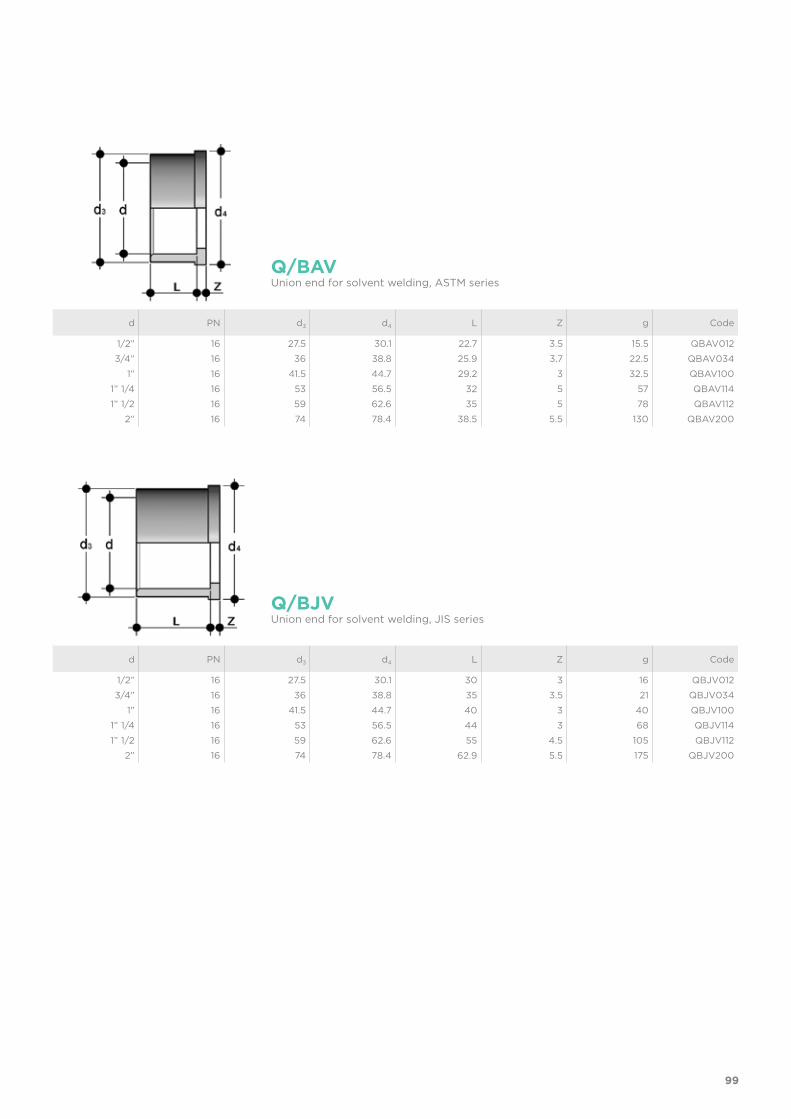
99
d PN d3 d4 L Z g Code
1/2” 16 27.5 30.1 22.7 3.5 15.5 QBAV012 3/4” 16 36 38.8 25.9 3.7 22.5 QBAV034
1” 16 41.5 44.7 29.2 3 32.5 QBAV100 1” 1/4 16 53 56.5 32 5 57 QBAV114 1” 1/2 16 59 62.6 35 5 78 QBAV112
2” 16 74 78.4 38.5 5.5 130 QBAV200
Q/BAVUnion end for solvent welding, ASTM series
d PN d3 d4 L Z g Code
1/2” 16 27.5 30.1 30 3 16 QBJV012 3/4” 16 36 38.8 35 3.5 21 QBJV034
1” 16 41.5 44.7 40 3 40 QBJV100 1” 1/4 16 53 56.5 44 3 68 QBJV114 1” 1/2 16 59 62.6 55 4.5 105 QBJV112
2” 16 74 78.4 62.9 5.5 175 QBJV200
Q/BJVUnion end for solvent welding, JIS series
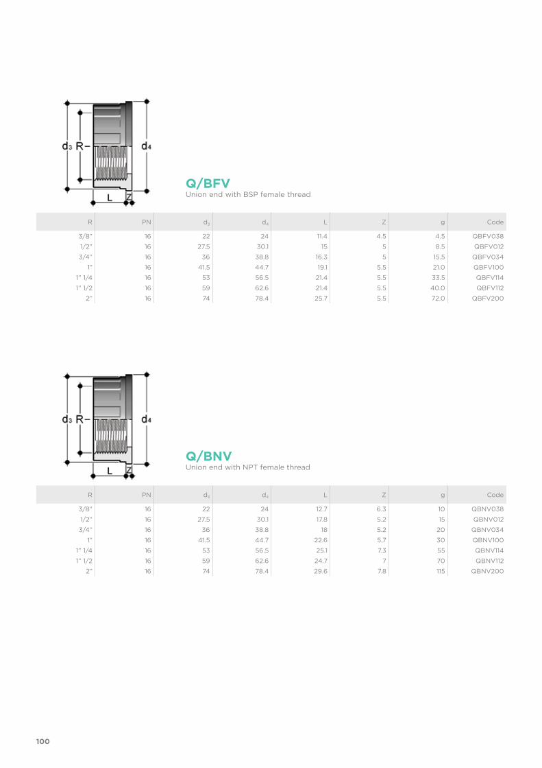
100
R PN d3 d4 L Z g Code
3/8” 16 22 24 11.4 4.5 4.5 QBFV0381/2” 16 27.5 30.1 15 5 8.5 QBFV0123/4” 16 36 38.8 16.3 5 15.5 QBFV034
1” 16 41.5 44.7 19.1 5.5 21.0 QBFV1001” 1/4 16 53 56.5 21.4 5.5 33.5 QBFV1141” 1/2 16 59 62.6 21.4 5.5 40.0 QBFV112
2” 16 74 78.4 25.7 5.5 72.0 QBFV200
R PN d3 d4 L Z g Code
3/8” 16 22 24 12.7 6.3 10 QBNV0381/2” 16 27.5 30.1 17.8 5.2 15 QBNV0123/4” 16 36 38.8 18 5.2 20 QBNV034
1” 16 41.5 44.7 22.6 5.7 30 QBNV1001” 1/4 16 53 56.5 25.1 7.3 55 QBNV1141” 1/2 16 59 62.6 24.7 7 70 QBNV112
2” 16 74 78.4 29.6 7.8 115 QBNV200
Q/BFV
Q/BNV
Union end with BSP female thread
Union end with NPT female thread
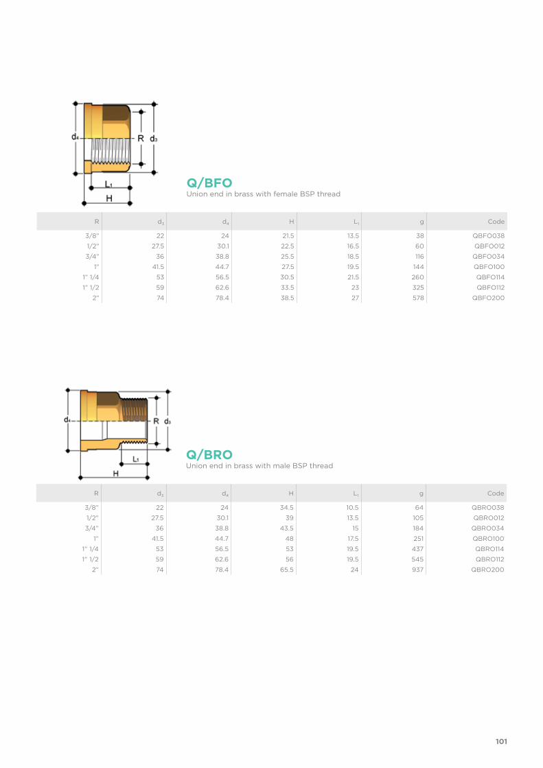
101
R d3 d4 H L1 g Code
3/8” 22 24 34.5 10.5 64 QBRO0381/2” 27.5 30.1 39 13.5 105 QBRO0123/4” 36 38.8 43.5 15 184 QBRO034
1” 41.5 44.7 48 17.5 251 QBRO1001” 1/4 53 56.5 53 19.5 437 QBRO1141” 1/2 59 62.6 56 19.5 545 QBRO112
2” 74 78.4 65.5 24 937 QBRO200
Q/BROUnion end in brass with male BSP thread
R d3 d4 H L1 g Code
3/8” 22 24 21.5 13.5 38 QBFO0381/2” 27.5 30.1 22.5 16.5 60 QBFO0123/4” 36 38.8 25.5 18.5 116 QBFO034
1” 41.5 44.7 27.5 19.5 144 QBFO1001” 1/4 53 56.5 30.5 21.5 260 QBFO1141” 1/2 59 62.6 33.5 23 325 QBFO112
2” 74 78.4 38.5 27 578 QBFO200
Q/BFOUnion end in brass with female BSP thread
102
R d3 d4 H L1 g Code
3/8” 22 24 21.5 13.5 34 QBFX0381/2” 27.5 30.1 22.5 16.5 54 QBFX0123/4” 36 38.8 25.5 18.5 104 QBFX034
1” 41.5 44.7 27.5 19.5 130 QBFX1001” 1/4 53 56.5 30.5 21.5 234 QBFX1141” 1/2 59 62.6 33.5 23 293 QBFX112
2” 74 78.4 38.5 27 520 QBFX200
Q/BFXUnion end in A316L stainless steel with female BSP thread
R d3 d4 H L1 g Code
3/8” 22 24 34.5 10.5 58 QBRX0381/2” 27.5 30.1 39 13.5 95 QBRX0123/4” 36 38.8 43.5 15 166 QBRX034
1” 41.5 44.7 48 17.5 226 QBRX1001” 1/4 53 56.5 53 19.5 393 QBRX1141” 1/2 59 62.6 56 19.5 491 QBRX112
2” 74 78.4 65.5 24 843 QBRX200
Q/BRXUnion end in A316L stainless steel with male BSP thread
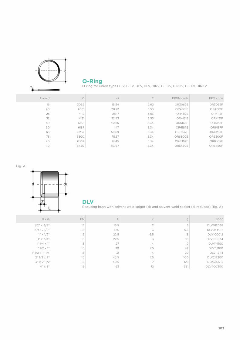
103
Union d C di T EPDM code FPM code
16 3062 15.54 2.62 OR3062E OR3062F20 4081 20.22 3.53 OR4081E OR4081F25 4112 28.17 3.53 OR4112E OR4112F32 4131 32.93 3.53 OR4131E OR4131F40 6162 40.65 5.34 OR6162E OR6162F50 6187 47 5.34 OR6187E OR6187F63 6237 59.69 5.34 OR6237E OR6237F75 6300 75.57 5.34 OR6300E OR6300F90 6362 91.45 5.34 OR6362E OR6362F110 6450 113.67 5.34 OR6450E OR6450F
O-RingO-ring for union types BIV, BIFV, BFV, BLV, BIRV, BIFOV, BIROV, BIFXV, BIRXV
d x d1 PN L Z g Code
1/2” x 3/8” 15 16.5 2 3 DLV0120383/4” x 1/2” 15 19.5 3 5.5 DLV034012
1” x 1/2” 15 22.5 6.5 18 DLV1000121” x 3/4” 15 22.5 3 10 DLV100034
1” 1/4 x 1” 15 27 4 19 DLV1141001” 1/2 x 1” 15 30 7.5 42 DLV112100
1” 1/2 x 1” 1/4 15 31 4 20 DLV1121142” 1/2 x 2” 15 43.5 7.5 100 DLV2122003” x 2” 1/2 15 50.5 7 125 DLV300212
4” x 3” 15 63 12 331 DLV400300
DLVReducing bush with solvent weld spigot (d) and solvent weld socket (d1 reduced) (fig. A)
Fig. A
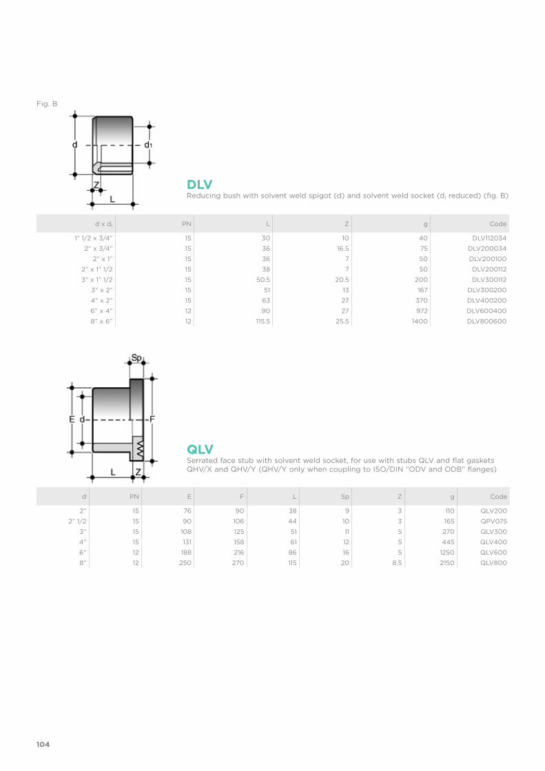
104
d x d1 PN L Z g Code
1” 1/2 x 3/4” 15 30 10 40 DLV1120342” x 3/4” 15 36 16.5 75 DLV200034
2” x 1” 15 36 7 50 DLV2001002” x 1” 1/2 15 38 7 50 DLV2001123” x 1” 1/2 15 50.5 20.5 200 DLV300112
3” x 2” 15 51 13 167 DLV3002004” x 2” 15 63 27 370 DLV4002006” x 4” 12 90 27 972 DLV6004008” x 6” 12 115.5 25.5 1400 DLV800600
DLVReducing bush with solvent weld spigot (d) and solvent weld socket (d1 reduced) (fig. B)
d PN E F L Sp Z g Code
2” 15 76 90 38 9 3 110 QLV2002” 1/2 15 90 106 44 10 3 165 QPV075
3” 15 108 125 51 11 5 270 QLV3004” 15 131 158 61 12 5 445 QLV4006” 12 188 216 86 16 5 1250 QLV6008” 12 250 270 115 20 8.5 2150 QLV800
QLVSerrated face stub with solvent weld socket, for use with stubs QLV and flat gaskets QHV/X and QHV/Y (QHV/Y only when coupling to ISO/DIN “ODV and ODB” flanges)
Fig. B
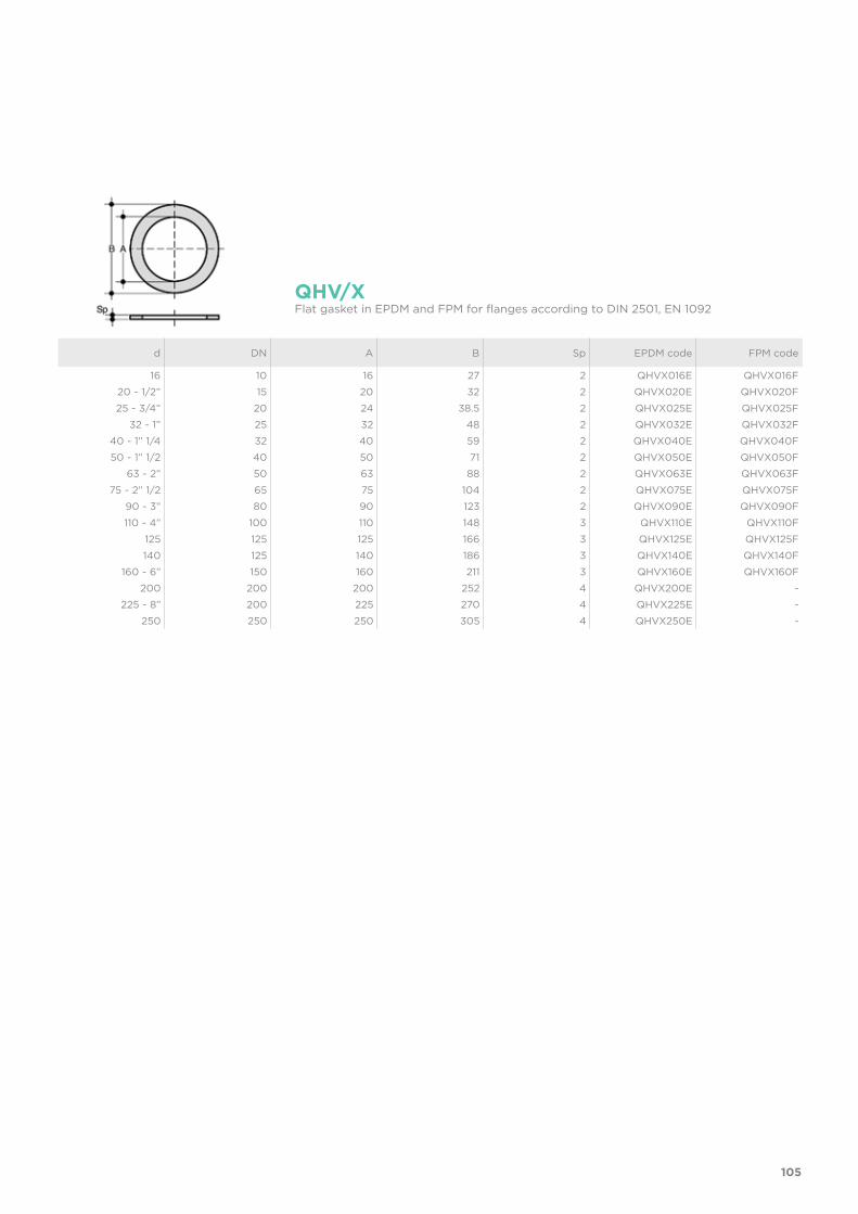
105
d DN A B Sp EPDM code FPM code
16 10 16 27 2 QHVX016E QHVX016F20 - 1/2” 15 20 32 2 QHVX020E QHVX020F25 - 3/4” 20 24 38.5 2 QHVX025E QHVX025F
32 - 1” 25 32 48 2 QHVX032E QHVX032F40 - 1” 1/4 32 40 59 2 QHVX040E QHVX040F50 - 1” 1/2 40 50 71 2 QHVX050E QHVX050F
63 - 2” 50 63 88 2 QHVX063E QHVX063F75 - 2” 1/2 65 75 104 2 QHVX075E QHVX075F
90 - 3” 80 90 123 2 QHVX090E QHVX090F110 - 4” 100 110 148 3 QHVX110E QHVX110F
125 125 125 166 3 QHVX125E QHVX125F140 125 140 186 3 QHVX140E QHVX140F
160 - 6” 150 160 211 3 QHVX160E QHVX160F200 200 200 252 4 QHVX200E -
225 - 8” 200 225 270 4 QHVX225E -250 250 250 305 4 QHVX250E -
QHV/X Flat gasket in EPDM and FPM for flanges according to DIN 2501, EN 1092
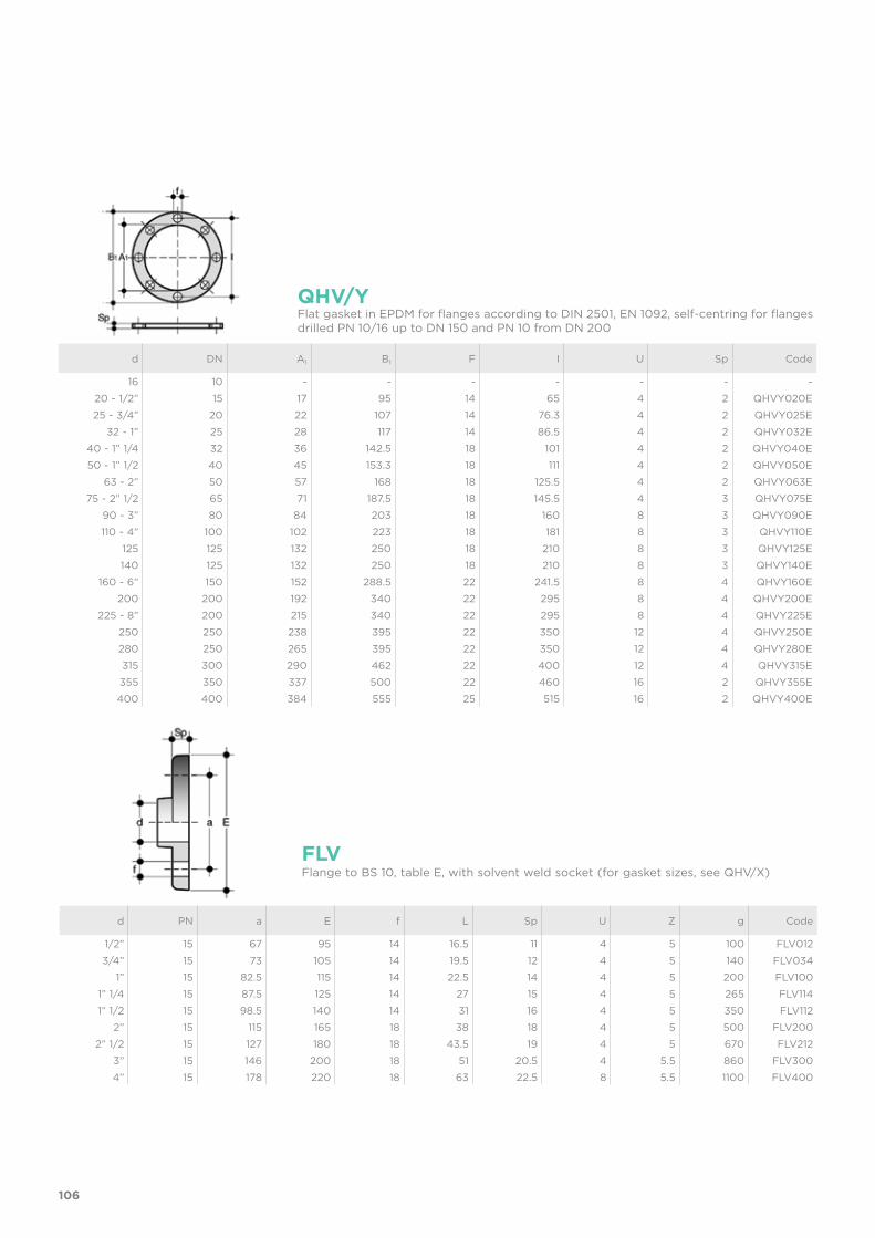
106
d PN a E f L Sp U Z g Code
1/2” 15 67 95 14 16.5 11 4 5 100 FLV0123/4” 15 73 105 14 19.5 12 4 5 140 FLV034
1” 15 82.5 115 14 22.5 14 4 5 200 FLV1001” 1/4 15 87.5 125 14 27 15 4 5 265 FLV1141” 1/2 15 98.5 140 14 31 16 4 5 350 FLV112
2” 15 115 165 18 38 18 4 5 500 FLV2002” 1/2 15 127 180 18 43.5 19 4 5 670 FLV212
3” 15 146 200 18 51 20.5 4 5.5 860 FLV3004” 15 178 220 18 63 22.5 8 5.5 1100 FLV400
FLVFlange to BS 10, table E, with solvent weld socket (for gasket sizes, see QHV/X)
d DN A1 B1 F I U Sp Code
16 10 - - - - - - -20 - 1/2” 15 17 95 14 65 4 2 QHVY020E25 - 3/4” 20 22 107 14 76.3 4 2 QHVY025E
32 - 1” 25 28 117 14 86.5 4 2 QHVY032E40 - 1” 1/4 32 36 142.5 18 101 4 2 QHVY040E50 - 1” 1/2 40 45 153.3 18 111 4 2 QHVY050E
63 - 2” 50 57 168 18 125.5 4 2 QHVY063E75 - 2” 1/2 65 71 187.5 18 145.5 4 3 QHVY075E
90 - 3” 80 84 203 18 160 8 3 QHVY090E110 - 4” 100 102 223 18 181 8 3 QHVY110E
125 125 132 250 18 210 8 3 QHVY125E140 125 132 250 18 210 8 3 QHVY140E
160 - 6” 150 152 288.5 22 241.5 8 4 QHVY160E200 200 192 340 22 295 8 4 QHVY200E
225 - 8” 200 215 340 22 295 8 4 QHVY225E250 250 238 395 22 350 12 4 QHVY250E280 250 265 395 22 350 12 4 QHVY280E315 300 290 462 22 400 12 4 QHVY315E355 350 337 500 22 460 16 2 QHVY355E400 400 384 555 25 515 16 2 QHVY400E
QHV/YFlat gasket in EPDM for flanges according to DIN 2501, EN 1092, self-centring for flanges drilled PN 10/16 up to DN 150 and PN 10 from DN 200
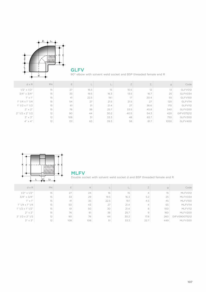
107
d x R PN E L L1 Z Z1 g Code
1/2” x 1/2” 15 27 16.5 15 10.5 12 13 GLFV0123/4” x 3/4” 15 33 19.5 16.3 13.5 16.7 25 GLFV034
1” x 1” 15 41 22.5 19.1 17 20.4 55 GLFV1001” 1/4 x 1” 1/4 15 54 27 21.5 21.5 27 120 GLFV1141” 1/2 x 1” 1/2 15 61 31 21.4 27 36.6 170 GLFV112
2” x 2” 15 76 38 25.7 33.5 45.8 340 GLFV2002” 1/2 x 2” 1/2 12 90 44 30.2 40.5 54.3 420 GIFV075212
3” x 3” 12 108 51 33.3 48 65.7 750 GLFV3004” x 4” 12 131 63 39.3 58 81.7 1050 GLFV400
GLFV90° elbow with solvent weld socket and BSP threaded female end R
d x R PN E K L L1 Z g Code
1/2” x 1/2” 15 27 24 16 15 4 15 MLFV0123/4” x 3/4” 15 33 29 19.5 16.3 5.2 25 MLFV034
1” x 1” 15 41 35 22.5 19.1 4.5 45 MLFV1001” 1/4 x 1” 1/4 15 50 43 27 21.4 4 65 MLFV114
1” 1/2 x 1” 1/2” 15 61 50 30 21.4 8 100 MLFV1122” x 2” 15 76 61 36 25.7 9 160 MLFV200
2” 1/2 x 2” 1/2 12 90 76 44 30.2 17.8 260 DIFV0900752123” x 3” 12 108 108 51 33.3 22.7 449 MLFV300
MLFVDouble socket with solvent weld socket d and BSP threaded female end R
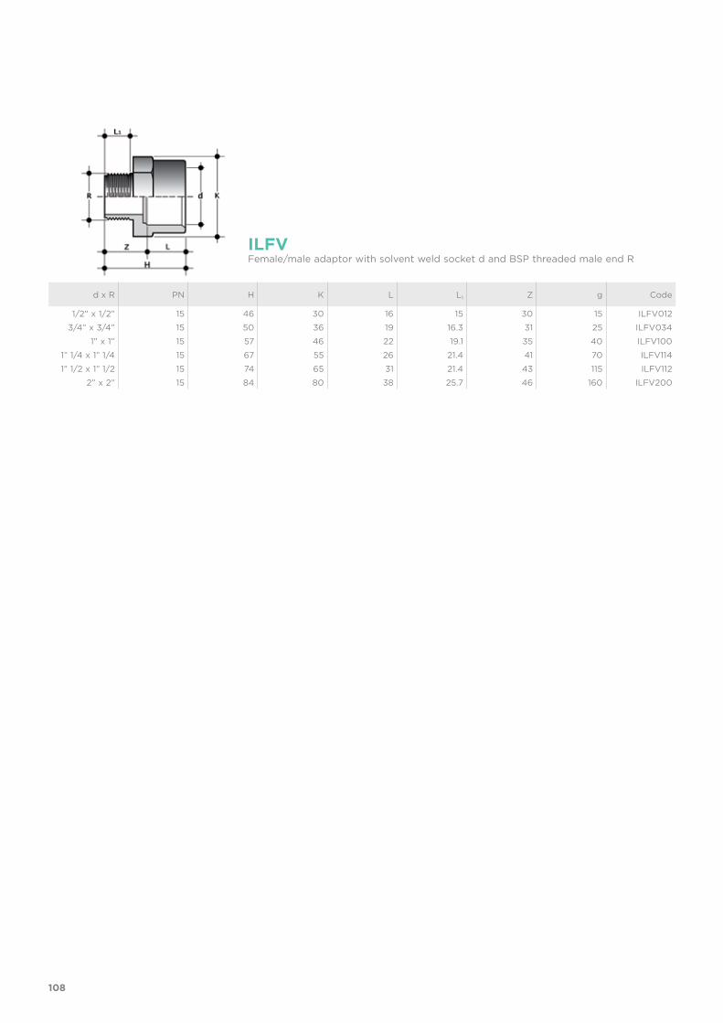
108
d x R PN H K L L1 Z g Code
1/2” x 1/2” 15 46 30 16 15 30 15 ILFV0123/4” x 3/4” 15 50 36 19 16.3 31 25 ILFV034
1” x 1” 15 57 46 22 19.1 35 40 ILFV1001” 1/4 x 1” 1/4 15 67 55 26 21.4 41 70 ILFV1141” 1/2 x 1” 1/2 15 74 65 31 21.4 43 115 ILFV112
2” x 2” 15 84 80 38 25.7 46 160 ILFV200
ILFVFemale/male adaptor with solvent weld socket d and BSP threaded male end R
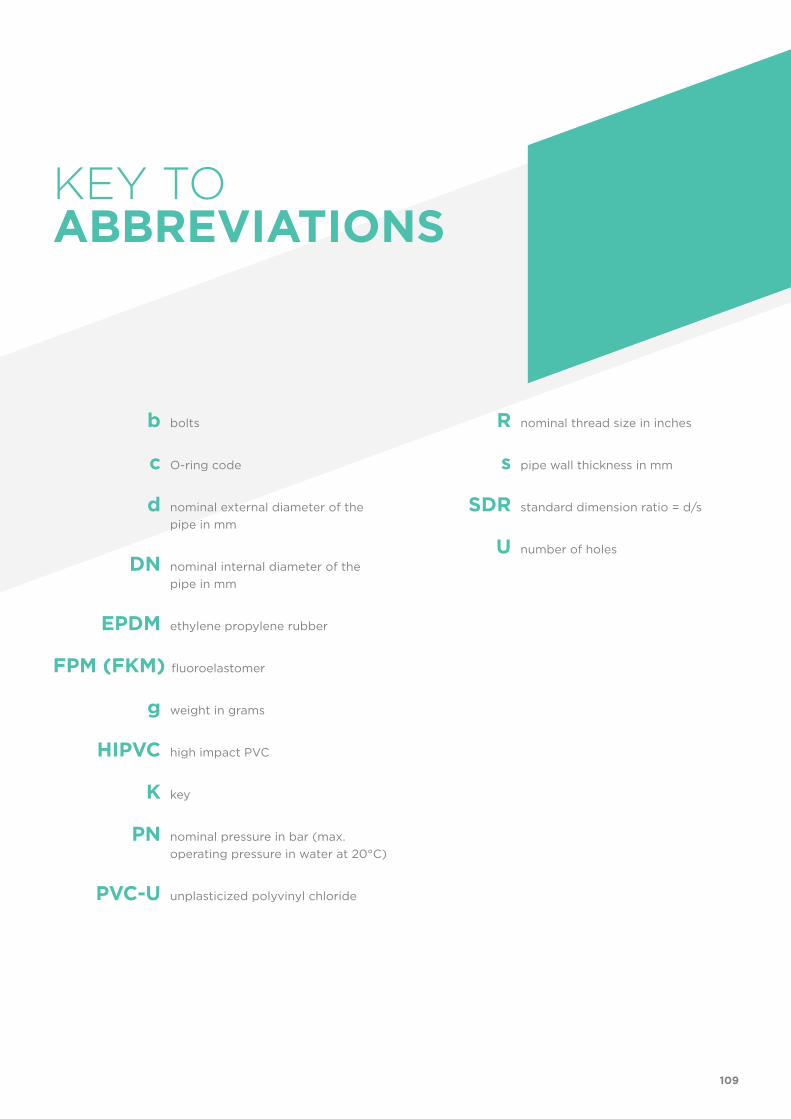
109
R nominal thread size in inches
s pipe wall thickness in mm
SDR standard dimension ratio = d/s
U number of holes
KEY TOABBREVIATIONS
b bolts
c O-ring code
d nominal external diameter of the pipe in mm
DN nominal internal diameter of the pipe in mm
EPDM ethylene propylene rubber
FPM (FKM) fluoroelastomer
g weight in grams
HIPVC high impact PVC
K key
PN nominal pressure in bar (max. operating pressure in water at 20°C)
PVC-U unplasticized polyvinyl chloride